JP7168775B2 - Device for adjusting the mixing ratio of gas mixtures - Google Patents
Device for adjusting the mixing ratio of gas mixtures Download PDFInfo
- Publication number
- JP7168775B2 JP7168775B2 JP2021518165A JP2021518165A JP7168775B2 JP 7168775 B2 JP7168775 B2 JP 7168775B2 JP 2021518165 A JP2021518165 A JP 2021518165A JP 2021518165 A JP2021518165 A JP 2021518165A JP 7168775 B2 JP7168775 B2 JP 7168775B2
- Authority
- JP
- Japan
- Prior art keywords
- gas
- sensor
- thermal
- parameter
- air
- Prior art date
- Legal status (The legal status is an assumption and is not a legal conclusion. Google has not performed a legal analysis and makes no representation as to the accuracy of the status listed.)
- Active
Links
Images


Classifications
-
- F—MECHANICAL ENGINEERING; LIGHTING; HEATING; WEAPONS; BLASTING
- F23—COMBUSTION APPARATUS; COMBUSTION PROCESSES
- F23N—REGULATING OR CONTROLLING COMBUSTION
- F23N1/00—Regulating fuel supply
- F23N1/02—Regulating fuel supply conjointly with air supply
- F23N1/022—Regulating fuel supply conjointly with air supply using electronic means
-
- F—MECHANICAL ENGINEERING; LIGHTING; HEATING; WEAPONS; BLASTING
- F23—COMBUSTION APPARATUS; COMBUSTION PROCESSES
- F23N—REGULATING OR CONTROLLING COMBUSTION
- F23N5/00—Systems for controlling combustion
- F23N5/02—Systems for controlling combustion using devices responsive to thermal changes or to thermal expansion of a medium
- F23N5/025—Systems for controlling combustion using devices responsive to thermal changes or to thermal expansion of a medium using electrical or electromechanical means
-
- F—MECHANICAL ENGINEERING; LIGHTING; HEATING; WEAPONS; BLASTING
- F23—COMBUSTION APPARATUS; COMBUSTION PROCESSES
- F23N—REGULATING OR CONTROLLING COMBUSTION
- F23N5/00—Systems for controlling combustion
- F23N5/18—Systems for controlling combustion using detectors sensitive to rate of flow of air or fuel
- F23N5/187—Systems for controlling combustion using detectors sensitive to rate of flow of air or fuel using electrical or electromechanical means
-
- F—MECHANICAL ENGINEERING; LIGHTING; HEATING; WEAPONS; BLASTING
- F23—COMBUSTION APPARATUS; COMBUSTION PROCESSES
- F23N—REGULATING OR CONTROLLING COMBUSTION
- F23N5/00—Systems for controlling combustion
- F23N5/18—Systems for controlling combustion using detectors sensitive to rate of flow of air or fuel
- F23N2005/181—Systems for controlling combustion using detectors sensitive to rate of flow of air or fuel using detectors sensitive to rate of flow of air
-
- F—MECHANICAL ENGINEERING; LIGHTING; HEATING; WEAPONS; BLASTING
- F23—COMBUSTION APPARATUS; COMBUSTION PROCESSES
- F23N—REGULATING OR CONTROLLING COMBUSTION
- F23N5/00—Systems for controlling combustion
- F23N5/18—Systems for controlling combustion using detectors sensitive to rate of flow of air or fuel
- F23N2005/185—Systems for controlling combustion using detectors sensitive to rate of flow of air or fuel using detectors sensitive to rate of flow of fuel
-
- F—MECHANICAL ENGINEERING; LIGHTING; HEATING; WEAPONS; BLASTING
- F23—COMBUSTION APPARATUS; COMBUSTION PROCESSES
- F23N—REGULATING OR CONTROLLING COMBUSTION
- F23N2221/00—Pretreatment or prehandling
- F23N2221/10—Analysing fuel properties, e.g. density, calorific
-
- F—MECHANICAL ENGINEERING; LIGHTING; HEATING; WEAPONS; BLASTING
- F23—COMBUSTION APPARATUS; COMBUSTION PROCESSES
- F23N—REGULATING OR CONTROLLING COMBUSTION
- F23N2225/00—Measuring
- F23N2225/04—Measuring pressure
- F23N2225/06—Measuring pressure for determining flow
-
- F—MECHANICAL ENGINEERING; LIGHTING; HEATING; WEAPONS; BLASTING
- F23—COMBUSTION APPARATUS; COMBUSTION PROCESSES
- F23N—REGULATING OR CONTROLLING COMBUSTION
- F23N2239/00—Fuels
- F23N2239/04—Gaseous fuels
Landscapes
- Engineering & Computer Science (AREA)
- Chemical & Material Sciences (AREA)
- Combustion & Propulsion (AREA)
- Mechanical Engineering (AREA)
- General Engineering & Computer Science (AREA)
- Investigating Or Analyzing Materials Using Thermal Means (AREA)
- Regulation And Control Of Combustion (AREA)
Description
本発明は、第1のガスと第2のガスとを含むガス混合物の混合比を調節するための装置、及び、対応する方法に関する。 The present invention relates to a device and a corresponding method for adjusting the mixing ratio of a gas mixture comprising a first gas and a second gas.
ガス作動エネルギー変換器、例えば、ガスバーナーや、ガスエンジン又はガスモーターなどの内燃機関を適切に作動させるために重要な量が、エネルギー変換器に供給される空気-燃料混合物の混合比である。混合比はさまざまな方法で定義することができる。本明細書では、混合比を、空気-燃料混合物中の燃料のv/v濃度で表す。しかしながら、他の定義を用いることもできる。燃料濃度が高すぎると、煤煙が発生するおそれがある。一方、燃料濃度が低すぎると、エネルギー変換器の性能が低下するおそれがある。従って、混合比は慎重に調節されなければならない。 An important quantity for proper operation of a gas-operated energy converter, such as a gas burner or an internal combustion engine such as a gas engine or gas motor, is the mixture ratio of the air-fuel mixture supplied to the energy converter. The mix ratio can be defined in various ways. As used herein, mixture ratios are expressed as the v/v concentration of fuel in the air-fuel mixture. However, other definitions can also be used. If the fuel concentration is too high, soot may be generated. On the other hand, if the fuel concentration is too low, the performance of the energy converter may deteriorate. Therefore, the mixing ratio must be carefully adjusted.
特許文献1は、ガスバーナー用の調整システムを開示する。燃料ガス流と燃焼空気流がバーナーに供給される。燃料ガス流は、燃焼空気流の圧力に応じて調整される。この目的のために、差圧センサが燃料ガス流と燃焼空気流の間に配置される。差圧センサは、燃料ガス用のガスバルブを調整するために使用される電気信号を発生する。 US Pat. No. 6,300,009 discloses a regulation system for gas burners. A stream of fuel gas and a stream of combustion air are supplied to the burner. The fuel gas flow is regulated in response to the combustion air flow pressure. For this purpose, a differential pressure sensor is arranged between the fuel gas stream and the combustion air stream. A differential pressure sensor produces an electrical signal that is used to regulate the gas valve for the fuel gas.
特許文献2は、ガス作動エネルギー変換プラントにおいて酸素キャリアガス(oxygen carrier gas)と燃料ガスとの間の混合比を調節するための方法を開示する。混合比を調節するために、酸素キャリアガス及び/又は燃料ガスの質量流量又は体積流量が検出される。質量流量又は体積流量や、熱伝導率又は熱容量など、燃料ガスの少なくとも2つの物理的パラメータが、センサを使用して測定される。これらの物理的パラメータから、混合比の目標値が決定される。この目標値は、混合比の調節のために用いられる。 US Pat. No. 5,300,000 discloses a method for adjusting the mixing ratio between oxygen carrier gas and fuel gas in gas-operated energy conversion plants. The mass or volumetric flow rate of oxygen carrier gas and/or fuel gas is sensed to adjust the mixture ratio. At least two physical parameters of the fuel gas are measured using sensors, such as mass or volume flow rate and thermal conductivity or heat capacity. From these physical parameters the target value of the mixing ratio is determined. This target value is used for adjusting the mixing ratio.
特許文献3は、燃焼システムの燃焼室内において空気と燃料ガスの混合物を制御するための燃焼コントローラを開示する。燃焼コントローラは、さまざまなセンサからのセンサ入力に基づいて、燃料導管内の燃料バルブを開閉し、空気導管内のエアダンパーを開閉することによって混合物を制御する。これらのセンサには、燃料と空気の流れ特性を測定するための、燃料導管と空気導管に置かれた流量センサが含まれる。これらセンサには、さらに、燃料の熱パラメータを測定するための、燃料導管に置かれた追加のセンサが含まれ、このセンサは、直接流に曝されないように、燃料導管の行き止まりになっている空洞に入れ置かれている。これらセンサは、さらに、圧力センサ及び温度センサを含むことができる。 US Pat. No. 5,300,004 discloses a combustion controller for controlling the mixture of air and fuel gas within the combustion chamber of a combustion system. The combustion controller controls the mixture by opening and closing a fuel valve in the fuel conduit and an air damper in the air conduit based on sensor inputs from various sensors. These sensors include flow sensors placed in the fuel and air conduits for measuring fuel and air flow characteristics. These sensors further include additional sensors placed in the fuel conduit for measuring thermal parameters of the fuel, which are dead-ended in the fuel conduit so as not to be exposed to direct flow. placed in a cavity. These sensors may further include pressure sensors and temperature sensors.
これら従来技術のシステムにおいて、混合比の調節は、空気と燃料ガスが混合される地点から上流側での空気流と燃料ガス流の流量測定に基づいている。しかしながら、これはさまざまな理由で問題になる可能性がある。第1に、空気流量は通常、燃料ガス流量よりもはるかに大きく、混合気中の典型的な燃料濃度はわずか10%v/vの範囲にある。これにより、空気流と燃料流の流量センサに異なる要求が課せられる。第2に、最新のガスバーナーは加熱ダイナミックレンジ(dynamic heating range)を大きくすることができ、最大燃料需要と最小燃料需要の比率が10:1、さらには20:1を容易に超えることができる。このため、空気流と燃料流に対する流量センサのそれぞれは、広い流量範囲をカバーする必要がある。同時に、すべての作動条件に対し、最高の精度と長期安定性が求められる。現在入手可能な流量センサは、たいていの場合、これらの高い要求を満たすことができない。 In these prior art systems, the adjustment of the mixture ratio is based on flow measurements of the air and fuel gas streams upstream from the point where the air and fuel gas are mixed. However, this can be problematic for various reasons. First, the air flow rate is usually much higher than the fuel gas flow rate, and typical fuel concentrations in the mixture are in the range of only 10% v/v. This imposes different demands on the air flow and fuel flow sensors. Second, modern gas burners can have a large dynamic heating range, easily exceeding a ratio of maximum to minimum fuel demand of 10:1 or even 20:1. . Therefore, each of the flow sensors for air flow and fuel flow must cover a wide flow range. At the same time, maximum precision and long-term stability are required for all operating conditions. Currently available flow sensors are often unable to meet these high demands.
同様の問題は、燃料ガスと空気以外のガスの混合、特に機能性ガスと酸素キャリアガスの混合、例えば、ガス麻酔薬と空気の混合にも存在する。 Similar problems exist with mixtures of fuel gases and gases other than air, in particular mixtures of functional gases and oxygen carrier gases, for example mixtures of gaseous anesthetics and air.
本発明の目的は、第1のガスと第2のガスとの間の混合比を、これらの流量の間に大きな違いが存在していても、これらガスの絶対流量の広いダイナミックレンジにわたって、信頼でき且つ正確に制御することのできる調節装置を提供することである。 It is an object of the present invention to provide a reliable mixing ratio between a first gas and a second gas over a wide dynamic range of absolute flow rates of these gases, even in the presence of large differences between these flow rates. To provide an adjustment device which can be controlled accurately.
この目的は、請求項1の特徴を有する調節装置によって達成される。本発明のさらなる実施形態は、従属請求項に記載されている。
This object is achieved by an adjusting device having the features of
第1のガスと第2のガスとを含むガス混合物の混合比を調節するための調節装置であって、以下を備える装置を提案する:
第1のガスの流れを運ぶための第1の導管;
第2のガスの流れを運ぶための導管であって、ガス混合物を生成するために、第1の導管とともに、混合領域で共通導管に開口する第2の導管;
ガス混合物の混合比を調整するための調整装置;及び
調整装置に対する制御信号を導出するように構成される制御装置。
A regulating device for regulating the mixing ratio of a gas mixture comprising a first gas and a second gas is proposed, the device comprising:
a first conduit for carrying a first gas flow;
a second conduit for carrying a second gas flow, the second conduit opening with the first conduit into a common conduit at the mixing zone to produce a gas mixture;
a regulator for adjusting the mixing ratio of the gas mixture; and a controller configured to derive a control signal for the regulator.
本発明の調節装置は、混合領域の下流側のガス混合物の少なくとも1つの熱パラメータを測定するように構成される第1のセンサを備える。上記制御装置は、この第1のセンサから、ガス混合物の上記少なくとも1つの熱パラメータを示すセンサ信号を受信し、上記少なくとも1つの熱パラメータに基づいて調整装置に対する制御信号を導出するように構成される。上記熱パラメータは、特に、ガス混合物の熱伝導率λ、熱拡散率D、比熱容量cp又は体積比熱容量(volumetric specific heat capacity)cpρ、あるいはこれらの任意の組み合わせを示すパラメータとすることができる。 The regulator of the invention comprises a first sensor configured to measure at least one thermal parameter of the gas mixture downstream of the mixing region. The controller is configured to receive from the first sensor a sensor signal indicative of the at least one thermal parameter of the gas mixture and derive a control signal for the regulator based on the at least one thermal parameter. be. Said thermal parameter may in particular be a parameter describing the thermal conductivity λ, the thermal diffusivity D, the specific heat capacity c p or the volumetric specific heat capacity c p p of the gas mixture, or any combination thereof. can be done.
本発明によれば、混合領域の下流側のガス混合物の少なくとも1つの熱パラメータの測定を行い、混合比を制御するためにこのパラメータを使用することが提案される。熱パラメータの値は概してガス混合物中の第1のガスと第2のガスとの間の混合比に依存する。重要な利点は、測定された熱パラメータが概して混合物の流量には依存しないことである。従って、センサは、流量に関係なく常にほぼ同じ動作点で作動され、提案された調節装置は、精度を損なうことなく、広い加熱ダイナミックレンジに適応できる。 According to the invention, it is proposed to measure at least one thermal parameter of the gas mixture downstream of the mixing zone and use this parameter for controlling the mixing ratio. The value of the thermal parameter generally depends on the mixing ratio between the first gas and the second gas in the gas mixture. An important advantage is that the measured thermal parameters are generally independent of the mixture flow rate. The sensor is therefore always operated at approximately the same operating point regardless of the flow rate, and the proposed regulator can accommodate a wide heating dynamic range without compromising accuracy.
多くの用途では、第2のガスの流量は第1のガスの流量よりもはるかに小さくなる。ガス混合物の少なくとも1つの熱パラメータの提案された測定は、ガス混合物中の第2のガスの濃度の決定に本質的に対応する。装置はそれに応じて構成することができる。特に、第2の導管は、第1の導管の断面積よりもはるかに小さい断面積を有してよい。いくつかの実施形態では、第1の導管の最小断面積(すなわち、導管の最も狭い位置での断面積)は、第2の導管の最小断面積の少なくとも5倍である。本発明の調節装置は、混合領域内の第1のガスの流れに第2のガスの流れを噴射するための1つ又は複数のノズルを備えることができる。このことは、主流が第1のガスの流れであるため有益である。噴射の方向は、混合領域のすぐ上流の第1のガスの流れ方向に対して軸方向、放射状、又は他の任意の角度であってよい。 In many applications, the flow rate of the second gas will be much less than the flow rate of the first gas. The proposed measurement of at least one thermal parameter of the gas mixture essentially corresponds to determining the concentration of the second gas in the gas mixture. The device can be configured accordingly. In particular, the second conduit may have a cross-sectional area much smaller than the cross-sectional area of the first conduit. In some embodiments, the minimum cross-sectional area of the first conduit (ie, the cross-sectional area at the narrowest point of the conduit) is at least five times the minimum cross-sectional area of the second conduit. The conditioning device of the present invention may comprise one or more nozzles for injecting the second gas flow into the first gas flow within the mixing region. This is beneficial because the main flow is the first gas flow. The direction of injection may be axial, radial, or at any other angle to the direction of flow of the first gas immediately upstream of the mixing region.
いくつかの実施形態では、第1のガスは酸素キャリアガスであり得、第2のガスは酸素キャリアガスと混合される何らかの機能性ガスであり得る。例えば、第1のガスは、空気、又は空気と排気ガスの混合物であり得、第2のガスは、燃料ガス、特に天然ガスであり得る。別の例として、第1のガスは、自然の空気、酸素富化空気、酸素と1つ又は複数の不活性ガスとの任意の他の混合物、又は、純粋な酸素ガスであり得、第2のガスは、医療用ガス、特に、イソフルランのような麻酔ガスであり得る。調節装置は、このようなガスと共に使用されるように特定的に構成されてよい。例えば、ガスバーナー用途の調節装置には、病院で麻酔剤を調合するための医療装置とは異なるコネクタと異なる材料を用いることになる。 In some embodiments, the first gas can be an oxygen carrier gas and the second gas can be any functional gas mixed with the oxygen carrier gas. For example, the first gas may be air or a mixture of air and exhaust gas, and the second gas may be fuel gas, in particular natural gas. As another example, the first gas can be natural air, oxygen-enriched air, any other mixture of oxygen and one or more inert gases, or pure oxygen gas; The gas may be a medical gas, especially an anesthetic gas such as isoflurane. Regulators may be specifically configured for use with such gases. For example, a regulator for a gas burner application would use different connectors and different materials than a medical device for dispensing anesthetics in a hospital.
いくつかの実施形態では、調整装置は、第2の導管内の第2のガスの流量を調整するための制御弁を含む。他の実施形態では、調整装置は、第2の導管内の第2のガスの流量を制御するために、制御可能なファン又はポンプを備えてよい。加えて又はこれに代えて、調整装置は、第1の導管内の第1のガスの流れを制御するために、弁、フラップ、あるいは、制御可能なファン又はポンプを備えてよい。 In some embodiments, the regulator includes a control valve for regulating the flow rate of the second gas within the second conduit. In other embodiments, the regulator may comprise a controllable fan or pump to control the flow rate of the second gas within the second conduit. Additionally or alternatively, the regulator may comprise a valve, flap, or controllable fan or pump to control the flow of the first gas within the first conduit.
有利な実施形態では、第1のセンサは、ガス混合物の1より多い熱パラメータを測定するように構成される。特に、第1のセンサは、ガス混合物の少なくとも2つの熱パラメータを測定するように構成することができ、これら熱パラメータは一緒になって、ガス混合物の熱伝導率及び熱拡散率を示す。 In an advantageous embodiment, the first sensor is arranged to measure more than one thermal parameter of the gas mixture. In particular, the first sensor can be configured to measure at least two thermal parameters of the gas mixture, which together are indicative of the thermal conductivity and thermal diffusivity of the gas mixture.
次に、制御装置は、前記少なくとも2つの熱パラメータを考慮するように構成することができる。これはさまざまな方法でなされ得る。例えば、制御装置は、第1のセンサによって測定される前記少なくとも2つの熱パラメータから導出される結合パラメータを求め、この結合パラメータに基づいて制御信号を導出するように構成することができる。他の実施形態では、制御装置を、第1のセンサによって測定される熱パラメータの第1のパラメータ、例えば熱伝導率に基づいて制御信号を導出し、第1のセンサによって測定される熱パラメータの第2のパラメータ、例えば熱拡散率に基づいて整合性チェック(consistency check)を実行するように構成することができる。整合性チェックが、第2の熱パラメータが第1の熱パラメータと矛盾していることを示した場合に、制御装置はエラー信号を発するように構成できる。このエラー信号により、調整装置が燃料ガスの流れを遮断するようにできる。このようにして、安全性を高めることができる。 The controller may then be configured to consider said at least two thermal parameters. This can be done in various ways. For example, the controller may be configured to determine a combined parameter derived from said at least two thermal parameters measured by the first sensor and to derive the control signal based on this combined parameter. In another embodiment, the controller is adapted to derive the control signal based on a first parameter of the thermal parameter measured by the first sensor, e.g. It can be configured to perform a consistency check based on a second parameter, eg thermal diffusivity. The controller can be configured to issue an error signal if the consistency check indicates that the second thermal parameter is inconsistent with the first thermal parameter. This error signal can cause the regulator to cut off the flow of fuel gas. In this way, safety can be enhanced.
上記第1のセンサは、混合比を調節するためだけでなく、第1のガスの密度又は圧力を求めるためにも用いることができる。特に、制御装置は、次の手順を実行するように構成できる:
調整装置を、第1のガスの流れがゼロでない流量を有すると同時に、第2のガスの流れが遮断される基準状態に設定するステップ;
第1のセンサからセンサ信号を受信し、該センサ信号は基準状態における第1のガスの少なくとも2つの熱パラメータを示すステップ;及び
基準状態における第1のガスの少なくとも2つの熱パラメータに基づいて、基準状態における第1のガスの密度又は圧力を示す圧力パラメータを求めるステップ。
The first sensor can be used not only to adjust the mixing ratio, but also to determine the density or pressure of the first gas. In particular, the controller can be configured to perform the following steps:
setting the regulator to a reference state in which the first gas flow has a non-zero flow rate while the second gas flow is blocked;
receiving a sensor signal from a first sensor, the sensor signal indicative of at least two thermal parameters of the first gas at reference conditions; and based on the at least two thermal parameters of the first gas at reference conditions, Determining a pressure parameter indicative of the density or pressure of the first gas in a reference state.
特に、第1のガスの密度は、その比熱容量が他の情報源から分かっている場合、その熱伝導率と熱拡散率から容易に計算できる。第1のガスの絶対圧力をその密度から計算するには、その温度を知る必要のある場合がある。この目的のために、第1のセンサは、それが曝されるガスの温度を測定するように構成することができ、制御装置は、圧力パラメータの決定を、第1のガスの少なくとも2つの熱パラメータだけでなく、第1のセンサによって測定されるその温度にも基づくように構成することができる。 In particular, the density of the first gas can be easily calculated from its thermal conductivity and thermal diffusivity if its specific heat capacity is known from other sources. To calculate the absolute pressure of the first gas from its density, it may be necessary to know its temperature. To this end, the first sensor can be configured to measure the temperature of the gas to which it is exposed, and the control device determines the pressure parameter by determining the temperature of at least two heats of the first gas. It can be configured to be based not only on the parameter, but also on its temperature measured by the first sensor.
同じ手順は、第2のガスの既知の比熱容量を使用し、場合によってはその温度を測定することにより、第2のガスに対しても実行することができる。 The same procedure can be performed for a second gas by using the known specific heat capacity of the second gas and possibly measuring its temperature.
有利な実施形態では、制御信号は、第1のセンサによって測定されるガス混合物の熱パラメータを、同じく第1のセンサによって測定される第1のガスの熱パラメータと比較する差分測定(differential measurement)に基づく。このようにして、第1のセンサの較正誤差(calibration errors)を大幅に相殺することができる。このために、制御装置は次の手順を実行するように構成できる:
調整装置を、第1のガスの流れがゼロでない流量を有すると同時に、第2のガスの流れが遮断される基準状態に設定するステップ;
第1のセンサからセンサ信号を受信し、該センサ信号は基準状態における第1のガスの少なくとも1つの熱パラメータを示すステップ;
調整装置を、第2のガスの流れ及び第1のガスの流れの両方がゼロでない流量を有する作動状態に設定するステップ;
第1のセンサからセンサ信号を受信し、該センサ信号は、今回は、作動状態におけるガス混合物の少なくとも1つの熱パラメータを示すステップ;及び、
作動状態におけるガス混合物の少なくとも1つの熱パラメータと、基準状態における第1のガスの少なくとも1つの熱パラメータとの比較に基づいて制御信号を導出するステップ。
上記比較は、例えば、ガス混合物の熱パラメータと第1のガスの熱パラメータの差又は商を算出することによって行うことができる。
In an advantageous embodiment, the control signal is a differential measurement comparing the thermal parameter of the gas mixture measured by the first sensor with the thermal parameter of the first gas also measured by the first sensor. based on. In this way, the calibration errors of the first sensor can be largely canceled out. To this end, the controller can be configured to perform the following steps:
setting the regulator to a reference state in which the first gas flow has a non-zero flow rate while the second gas flow is blocked;
receiving a sensor signal from a first sensor, the sensor signal indicative of at least one thermal parameter of the first gas at a reference condition;
setting the regulator to an operating state in which both the second gas flow and the first gas flow have non-zero flow rates;
receiving a sensor signal from the first sensor, the sensor signal now indicative of at least one thermal parameter of the gas mixture in the operating state; and
Deriving a control signal based on a comparison of at least one thermal parameter of the gas mixture in operating conditions and at least one thermal parameter of the first gas in reference conditions.
The comparison can be made, for example, by calculating the difference or quotient of the thermal parameters of the gas mixture and the first gas.
調節装置は、ガス混合物を使用場所に運ぶためのファンを備えることができる。「ファン」という用語は、ガス流を駆動することのできるあらゆる種類のブロワー又はポンプを包含するものとして広く理解されるべきである。いくつかの実施形態では、ファンは、混合領域の下流側、例えば、共通導管の下流端に配置することができる。他の実施形態では、ファンは、混合領域の上流側、例えば、第1の導管の上流端に配置することができる。ファンが混合領域の下流側に配置される場合、有利には、第1のセンサをファンに一体化することができる。 The conditioning device may comprise a fan for conveying the gas mixture to the point of use. The term "fan" should be understood broadly as encompassing any kind of blower or pump capable of driving a gas stream. In some embodiments, the fan can be positioned downstream of the mixing region, eg, at the downstream end of the common conduit. In other embodiments, the fan may be positioned upstream of the mixing region, eg, at the upstream end of the first conduit. If the fan is arranged downstream of the mixing area, the first sensor can advantageously be integrated into the fan.
第1のセンサは、ファンの閉塞や誤動作を検出するために使用できる。このために、制御装置は次の手順を実行するように構成できる:
第2のガスの流れが遮断されている間に、ファンを複数の異なる出力レベルで作動させるステップ;
各出力レベルに対して、第1のセンサから受信したセンサ信号に基づいて圧力パラメータを求め、該圧力パラメータは、前記出力レベルでの第1のガスの密度又は圧力を示すステップ;及び
さまざまな出力レベルでの圧力パラメータに基づいて、閉塞又はファンの誤動作が発生しているかどうかを示す閉塞信号(blockage signal)を導出するステップ。
A first sensor can be used to detect blockages or malfunctions of the fan. To this end, the controller can be configured to perform the following steps:
operating the fan at a plurality of different power levels while the flow of the second gas is interrupted;
determining, for each power level, a pressure parameter based on the sensor signal received from the first sensor, the pressure parameter indicative of the density or pressure of the first gas at said power level; and various outputs. Based on the pressure parameter at the level, deriving a blockage signal indicating whether a blockage or fan malfunction has occurred.
制御装置は、閉塞信号が閉塞又はファンの誤動作が発生していることを示す場合には、エラーメッセージを出力する、及び/又は、ファンを停止する、及び/又は、調整装置を、第1及び/又は第2のガスの流れが停止される状態に設定するように構成してもよい。 The controller outputs an error message and/or stops the fan and/or switches the regulator to the first and / Or it may be configured to set a state in which the flow of the second gas is stopped.
ガス混合物の均一性を改善するために、本発明の調節装置は、共通導管の、混合領域の下流側且つ第1のセンサの上流側にスワール部材を配備してよく、該スワール部材は、ガス混合物内に乱流を生成するように構成されている。 To improve the uniformity of the gas mixture, the regulator of the present invention may deploy a swirl member in the common conduit downstream of the mixing region and upstream of the first sensor, the swirl member It is configured to generate turbulence within the mixture.
第1のセンサに加えて、第1のガス及び/又は第2のガスの、1つ又は複数の熱パラメータを測定するための、1つ又は複数のさらなるセンサを使用することによって、調節を単純化及び改善することができる。 Simple regulation by using, in addition to the first sensor, one or more further sensors for measuring one or more thermal parameters of the first gas and/or the second gas can be refined and improved.
特に、本発明の調節装置は、第2のセンサを備えることができ、第2のセンサは、第1のガスの少なくとも1つの熱パラメータを測定するように構成される。第2のセンサは、混合領域の上流側の第1の導管に配置することができる。他の実施形態では、これは、混合領域を迂回するバイパス管路に配置することができる。制御装置は、第2のセンサから、第1のガスの少なくとも1つの熱パラメータを示すセンサ信号を受信し、第1及び第2のセンサの両方から受信したセンサ信号に基づいて制御信号を導出するように構成することができる。言い換えれば、制御装置は、第1のセンサによって測定されるガス混合物と第2のセンサによって測定される第1のガスの両方の、1つ又は複数の熱パラメータを考慮するように構成することができる。特に、制御装置は、第1のセンサによって測定されるガス混合物の少なくとも1つの熱パラメータと、第2のセンサによって測定される第1のガスの少なくとも1つの熱パラメータの比較に基づく制御信号を導出することによって、例えば、これらの熱パラメータの差又は商を算出することによって、ガス混合物及び第1のガスの差分測定を実行するように構成することができる。 In particular, the regulating device of the invention can comprise a second sensor, the second sensor being configured to measure at least one thermal parameter of the first gas. A second sensor may be placed in the first conduit upstream of the mixing region. In other embodiments, it can be placed in a bypass line that bypasses the mixing area. A controller receives from the second sensor a sensor signal indicative of at least one thermal parameter of the first gas and derives a control signal based on the sensor signals received from both the first and second sensors. can be configured as In other words, the controller may be configured to consider one or more thermal parameters of both the gas mixture measured by the first sensor and the first gas measured by the second sensor. can. In particular, the controller derives the control signal based on a comparison of at least one thermal parameter of the gas mixture measured by the first sensor and at least one thermal parameter of the first gas measured by the second sensor. It can be configured to perform a differential measurement of the gas mixture and the first gas by, for example, calculating the difference or quotient of these thermal parameters.
有利な実施形態では、第2のセンサは、第1のガスの密度及び/又は圧力を求めるために用いられる。この目的のために、第2のセンサは、少なくとも2つの熱パラメータを測定するように構成することができ、第2のセンサによって測定される少なくとも2つの熱パラメータは一緒になって、第1のガスの熱伝導率及び熱拡散率を示す。制御装置は、第2のセンサによって測定される少なくとも2つの熱パラメータに基づいて、第1のガスの密度又は圧力を示す酸素キャリア圧力パラメータを導出するように構成することができる。このようにして、調節装置の動作を監視するのに役立つ追加の診断パラメータが得られる。 In an advantageous embodiment a second sensor is used to determine the density and/or pressure of the first gas. To this end, the second sensor may be configured to measure at least two thermal parameters, the at least two thermal parameters measured by the second sensor taken together to form the first Thermal conductivity and thermal diffusivity of gases are shown. The controller may be configured to derive an oxygen carrier pressure parameter indicative of the density or pressure of the first gas based on at least two thermal parameters measured by the second sensor. In this way, additional diagnostic parameters are provided to help monitor the operation of the regulator.
有利な実施形態では、第2のセンサは、ガス混合物と第1のガスの差分測定を実行するためだけでなく、加えて整合性チェックも実行するために用いられる。この目的のために、第1のセンサは、少なくとも2つの熱パラメータを測定するように構成することができ、第1のセンサによって測定される少なくとも2つの熱パラメータは一緒になって、混合物の熱伝導率及び熱拡散率を示す。第2のセンサは、少なくとも2つの熱パラメータを測定するように構成することができ、第2のセンサによって測定される少なくとも2つの熱パラメータは一緒になって、第1のガスの熱伝導率及び熱拡散率を示す。制御装置は、第1及び第2のセンサによって測定される熱パラメータの1つ、例えば熱伝導率、の比較に基づいて制御信号を導出し、第1及び第2のセンサによって測定される少なくとも2つの熱パラメータの他の1つ、例えば、熱拡散率、の比較に基づいて整合性チェックを実行するように構成することができる。 In an advantageous embodiment, the second sensor is used not only to perform differential measurements of the gas mixture and the first gas, but also to perform consistency checks. To this end, the first sensor may be configured to measure at least two thermal parameters, the at least two thermal parameters measured by the first sensor together representing the heat of the mixture. Conductivity and thermal diffusivity are shown. The second sensor may be configured to measure at least two thermal parameters, the at least two thermal parameters measured by the second sensor taken together to be the thermal conductivity of the first gas and Indicates thermal diffusivity. The controller derives a control signal based on a comparison of one of the thermal parameters measured by the first and second sensors, e.g. thermal conductivity, and at least two parameters measured by the first and second sensors. A consistency check can be configured to be performed based on a comparison of one thermal parameter to another, eg, thermal diffusivity.
第1及び第2のセンサの両方は、ガスの熱パラメータに加えて、センサが曝されるそれぞれのガスの温度を測定するように構成することができる。特に、第1のセンサは、ガス混合物の温度を測定するように構成することができ、第2のセンサは、第1のガスの温度を測定するように構成することができる。このとき、制御装置は、ガス混合物と第1のガスの温度の比較に基づいて整合性チェックを実行するように構成することができる。これらの温度は少なくとも類似している必要がある。第1及び第2のセンサが、熱伝導性の共通の担体、例えば、共通のプリント回路基板上に取り付けられる場合、第1及び第2のセンサによって測定される温度間の差はさらに小さくなると予測される。 Both the first and second sensors can be configured to measure the temperature of the respective gas to which the sensor is exposed in addition to the thermal parameters of the gas. In particular, the first sensor can be configured to measure the temperature of the gas mixture and the second sensor can be configured to measure the temperature of the first gas. The controller can then be configured to perform a consistency check based on a comparison of the temperature of the gas mixture and the first gas. These temperatures should be at least similar. If the first and second sensors are mounted on a common thermally conductive carrier, such as a common printed circuit board, the difference between the temperatures measured by the first and second sensors is expected to be even smaller. be done.
いくつかの実施形態では、本発明の調節装置は、第2のガスの1つ又は複数の熱パラメータを考慮することができる。この目的のために、調節装置は、第3のセンサを備えることができ、第3のセンサは、第2のガスの少なくとも1つの熱パラメータを測定するように構成される。第3のセンサは、混合領域の上流側の第2の導管に配置することができる。制御装置は、第3のセンサから、第2のガスの上記少なくとも1つの熱パラメータを示すセンサ信号を受信し、第1及び第3のセンサの両方から受信したセンサ信号に基づいて制御信号を導出するように構成することができる。 In some embodiments, the regulator of the present invention can consider one or more thermal parameters of the second gas. To this end, the adjustment device may comprise a third sensor, the third sensor being arranged to measure at least one thermal parameter of the second gas. A third sensor may be placed in a second conduit upstream of the mixing region. The controller receives from the third sensor a sensor signal indicative of said at least one thermal parameter of the second gas and derives a control signal based on the sensor signals received from both the first and third sensors. can be configured to
調節装置が3つすべてのセンサ、すなわち、ガス混合物の1つ又は複数の熱パラメータを測定するための第1のセンサ、第1のガスの1つ又は複数の熱パラメータを測定するための第2のセンサ、及び、第2のガスの1つ又は複数の熱パラメータを測定するための第3のセンサを備えることも可能である。制御装置は、例えば、ガス混合物と第1のガスとの間、並びに第1のガスと第2のガスとの間で差分測定を実行するように構成することができる。この目的のために、制御装置は、第1のセンサによって測定されるガス混合物の熱パラメータを、第2のセンサによって測定される第1のガスの熱パラメータと比較し、第1のガスの前記熱パラメータを第3のセンサによって測定される第2のガスの熱パラメータと比較するように構成することができる。上記比較は、それぞれの熱パラメータの差又は商の算出を含んでよい。 The regulating device includes all three sensors, i.e. a first sensor for measuring one or more thermal parameters of the gas mixture, a second sensor for measuring one or more thermal parameters of the first gas. and a third sensor for measuring one or more thermal parameters of the second gas. The controller can be configured, for example, to perform differential measurements between the gas mixture and the first gas and between the first gas and the second gas. For this purpose, the control device compares the thermal parameter of the gas mixture measured by the first sensor with the thermal parameter of the first gas measured by the second sensor, and compares said thermal parameter of the first gas. The thermal parameter may be configured to be compared to a thermal parameter of the second gas measured by a third sensor. The comparison may include calculating the difference or quotient of the respective thermal parameters.
上記調節装置は、1つ又は複数の質量流量計によって補足することができる。特に、調節装置は、第1の導管内に第1の質量流量計を、及び/又は、第2の導管内に第2の質量流量計を備えることができ、上記制御装置は、第1及び/又は第2の質量流量計からの質量流量信号に基づいて、第1及び/又は第2の導管内の質量流量を示す1つ又は複数の質量流量パラメータを求めるように構成することができる。制御装置は、制御信号を導出するときにこうした質量流量パラメータを考慮するように構成することができる。他の実施形態では、第1のガスが酸素キャリアガスであり、第2のガスが燃料ガスである場合、制御装置は、1つ又は複数の質量流量パラメータに基づいて、ガス混合物流の火力を示す火力パラメータを求めるように構成することができる。 The adjustment device can be supplemented by one or more mass flow meters. In particular, the regulating device may comprise a first mass flow meter in the first conduit and/or a second mass flow meter in the second conduit, said controller comprising the first and One or more mass flow parameters indicative of the mass flow rate in the first and/or second conduits may be determined based on the mass flow signal from the second mass flow meter. The controller can be configured to consider such mass flow parameters when deriving the control signal. In other embodiments, where the first gas is an oxygen carrier gas and the second gas is a fuel gas, the controller determines the thermal power of the gas mixture stream based on one or more mass flow parameters. It can be configured to determine the indicated thermal power parameter.
第1又は第2の導管を通る質量流量は、第1及び第2の導管の間での差圧測定を行うことによって求めることもできる。この目的のために、調節装置は、第1又は第2の導管内の流量制限器と、流量制限器の上流側の、第1及び第2の導管の間の差圧を測定するように構成された差圧センサとを備えることができる。制御装置は、差圧センサからの差圧信号に基づいて、第1又は第2の導管内の質量流量を示す質量流量パラメータを求めるように構成することができる。 The mass flow rate through the first or second conduits can also be determined by taking differential pressure measurements between the first and second conduits. To this end, the regulator is configured to measure the differential pressure between the flow restrictor in the first or second conduit and the first and second conduits upstream of the flow restrictor. and a differential pressure sensor. The controller may be configured to determine a mass flow rate parameter indicative of mass flow rate in the first or second conduit based on the differential pressure signal from the differential pressure sensor.
本発明はさらに、第2のガスと第1のガスとを含むガス混合物の混合比を調節する、対応する方法を提供する。この方法は以下を含む:
第1のガスの流れを生成する工程;
第2のガスの流れを生成する工程;
混合領域で第1のガスと第2のガスの流れを混合することによってガス混合物を生成する工程;
第1のセンサを使用して、混合領域の下流側のガス混合物の少なくとも1つの熱パラメータを測定する工程;及び
上記少なくとも1つの熱パラメータに基づいて、混合比を調整する工程。
The invention further provides a corresponding method of adjusting the mixing ratio of a gas mixture comprising a second gas and a first gas. This method includes:
generating a first gas flow;
generating a second gas flow;
producing a gas mixture by mixing the first gas and second gas streams in a mixing region;
measuring at least one thermal parameter of the gas mixture downstream of the mixing region using a first sensor; and adjusting the mixing ratio based on said at least one thermal parameter.
混合比の調整する工程は、例えば、第2のガスの流量を調整するための制御弁を操作する工程を含むことができる。 The step of adjusting the mixing ratio can include, for example, the step of operating a control valve for adjusting the flow rate of the second gas.
上でより詳細に説明したように、第1のセンサを使用してガス混合物の少なくとも2つの熱パラメータを測定することが可能であり、これら少なくとも2つの熱パラメータは一緒になって、ガス混合物の熱伝導率及び熱拡散率を示し、混合比を調整するときに、ガス混合物のこれら少なくとも2つの熱パラメータを考慮することができる。特に、混合比は、第1のセンサによって測定された熱パラメータの1つに基づいて調整することができ、第1のセンサによって測定された熱パラメータの他の1つに基づいて整合性チェックを実行することができる。 As explained in more detail above, the first sensor can be used to measure at least two thermal parameters of the gas mixture, which together are the at least two thermal parameters of the gas mixture. These at least two thermal parameters of the gas mixture can be taken into account when indicating thermal conductivity and thermal diffusivity and adjusting the mixing ratio. In particular, the mixing ratio can be adjusted based on one of the thermal parameters measured by the first sensor and the consistency check based on another one of the thermal parameters measured by the first sensor. can be executed.
上でより詳細に説明したように、本方法の有利な実施形態は以下を含む:
第1のガスの流れがゼロでない流量を有すると同時に第2のガスの流れが遮断される基準状態を作り出す工程;
第1のセンサからセンサ信号を受信し、該センサ信号は基準状態における第1のガスの少なくとも2つの熱パラメータを示す工程;及び
基準状態における第1のガスの上記少なくとも2つの熱パラメータに基づいて、基準状態における第1のガスの密度又は圧力を示す圧力パラメータを求める工程。
As explained in more detail above, advantageous embodiments of the method include:
creating a reference condition in which the first gas flow has a non-zero flow rate while the second gas flow is shut off;
receiving a sensor signal from a first sensor, the sensor signal indicative of at least two thermal parameters of the first gas at a reference condition; and based on the at least two thermal parameters of the first gas at a reference condition. . Determining a pressure parameter indicative of the density or pressure of the first gas in a reference state.
上でより詳細に説明したように、本方法の有利な実施形態は以下を含む:
第1のガスの流れがゼロでない流量を有すると同時に第2のガスの流れが遮断される基準状態を作り出す工程;
第1のセンサからセンサ信号を受信し、該センサ信号は基準状態における第1のガスの少なくとも1つの熱パラメータを示す工程;
第2のガスの流れと第1のガスの流れの両方がゼロでない流量を有する作動状態を作り出す工程;
第1のセンサからセンサ信号を受信し、該センサ信号は作動状態におけるガス混合物の少なくとも1つの熱パラメータを示す工程;及び
作動状態におけるガス混合物の少なくとも1つの熱パラメータと、基準状態における第1のガスの少なくとも1つの熱パラメータとの比較に基づいて混合比を調整する工程。
As explained in more detail above, advantageous embodiments of the method include:
creating a reference condition in which the first gas flow has a non-zero flow rate while the second gas flow is shut off;
receiving a sensor signal from a first sensor, the sensor signal indicative of at least one thermal parameter of the first gas at a reference condition;
creating operating conditions in which both the second gas flow and the first gas flow have non-zero flow rates;
receiving a sensor signal from a first sensor, the sensor signal indicative of at least one thermal parameter of the gas mixture under operating conditions; and at least one thermal parameter of the gas mixture under operating conditions and the first thermal parameter under reference conditions. Adjusting the mixing ratio based on the comparison with at least one thermal parameter of the gas.
上でより詳細に説明したように、本方法は、ファンを使用してガス混合物を使用場所に運ぶ工程を含むことができる。その場合、この方法は以下を含むことができる:
第2のガスの流れが遮断されている間に、複数の異なる出力レベルでファンを作動させる工程;
各出力レベルに対して、第1のセンサによって測定されたセンサ信号から圧力パラメータを導出し、該圧力パラメータは前記出力レベルでの第1のガスの密度又は圧力を示す工程;及び
さまざまな出力レベルでの圧力パラメータに基づいて、閉塞又はファンの誤動作が発生しているかどうかを示す閉塞信号を導出する工程。
As described in more detail above, the method may include using a fan to convey the gas mixture to the point of use. In that case, the method may include:
operating the fan at a plurality of different power levels while the flow of the second gas is interrupted;
deriving, for each power level, a pressure parameter from the sensor signal measured by the first sensor, the pressure parameter indicative of the density or pressure of the first gas at said power level; and various power levels. deriving an occlusion signal indicating whether an occlusion or fan malfunction has occurred based on the pressure parameter at .
上でより詳細に説明したように、本方法は、さらに、第1のガスの1つ又は複数の熱パラメータを測定するための第2のセンサを使用することができる。特に、本方法は以下を含むことができる:
第2のセンサを使用して、混合領域の上流側の第1のガスの少なくとも1つの熱パラメータを測定する工程;及び
第1のセンサによって測定されたガス混合物の少なくとも1つの熱パラメータと、第2のセンサによって測定された第1のガスの少なくとも1つの熱パラメータとに基づいて混合比を調整する工程。
As described in more detail above, the method may further employ a second sensor for measuring one or more thermal parameters of the first gas. In particular, the method can include:
measuring at least one thermal parameter of the first gas upstream of the mixing region using a second sensor; and at least one thermal parameter of the gas mixture measured by the first sensor; adjusting the mixing ratio based on at least one thermal parameter of the first gas measured by the two sensors;
上でより詳細に説明したように、第2のセンサを使用して、第1のガスの密度又は圧力を求めることができる。特に、本方法は、第2のセンサによって少なくとも2つの熱パラメータを測定し、該第2のセンサによって測定された少なくとも2つの熱パラメータは一緒になって、第1のガスの熱伝導率及び熱拡散率を示す工程、及び、第2のセンサによって測定された少なくとも2つの熱パラメータに基づいて、酸素キャリア圧力パラメータを導出し、該酸素キャリア圧力パラメータは、第1のガスの密度又は圧力を示す工程を含むことができる。 As described in more detail above, a second sensor can be used to determine the density or pressure of the first gas. In particular, the method measures at least two thermal parameters by a second sensor, the at least two thermal parameters measured by the second sensor taken together to be the thermal conductivity and the thermal conductivity of the first gas. Deriving an oxygen carrier pressure parameter based on the step of indicating the diffusivity and the at least two thermal parameters measured by the second sensor, the oxygen carrier pressure parameter indicating the density or pressure of the first gas can include steps.
上でより詳細に説明したように、第2のセンサを使用して、整合性チェックを実行することができる。特に、本方法は以下を含むことができる:
第1のセンサを使用してガス混合物の少なくとも2つの熱パラメータを測定し、該第1のセンサによって測定された少なくとも2つの熱パラメータは一緒になって、ガス混合物の熱伝導率及び熱拡散率を示す工程;及び
第2のセンサを使用して第1のガスの、第1の熱パラメータ及び第2の熱パラメータを測定し、該第2のセンサによって測定された少なくとも2つの熱パラメータは一緒になって、第1のガスの熱伝導率及び熱拡散率を示す工程;
第1及び第2のセンサによって測定された熱パラメータの1つの比較に基づいて混合比を調整する工程;及び
第1及び第2のセンサによって測定された熱パラメータの他の1つの比較に基づいて整合性チェックを実行する工程。
As described in more detail above, a second sensor can be used to perform integrity checks. In particular, the method can include:
measuring at least two thermal parameters of the gas mixture using a first sensor, the at least two thermal parameters measured by the first sensor taken together to be thermal conductivity and thermal diffusivity of the gas mixture; and measuring a first thermal parameter and a second thermal parameter of the first gas using a second sensor, wherein the at least two thermal parameters measured by the second sensor are combined to indicate the thermal conductivity and thermal diffusivity of the first gas;
adjusting the mixing ratio based on a comparison of one of the thermal parameters measured by the first and second sensors; and based on a comparison of another one of the thermal parameters measured by the first and second sensors. The process of performing a consistency check.
上でより詳細に説明したように、本方法は以下を含むことができる:
第1のセンサを使用してガス混合物の温度を測定する工程;
第2のセンサを使用して第1のガスの温度を測定する工程;及び
混合ガスと第1のガスの温度の比較に基づいて整合性チェックを実行する工程。
As described in more detail above, the method can include:
measuring the temperature of the gas mixture using the first sensor;
measuring the temperature of the first gas using a second sensor; and performing a consistency check based on comparing the temperature of the mixed gas and the first gas.
上でより詳細に説明したように、この方法はさらに以下を含むことができる:
第3のセンサを使用して第2のガスの少なくとも1つの熱パラメータを測定する工程;及び
第1のセンサによって測定されたガス混合物の少なくとも1つの熱パラメータと、第3のセンサによって測定された第2のガスの少なくとも1つの熱パラメータとに基づいて混合比を調整する工程。
As described in more detail above, the method may further include:
measuring at least one thermal parameter of the second gas using a third sensor; and at least one thermal parameter of the gas mixture measured by the first sensor and measured by the third sensor. adjusting the mixing ratio based on at least one thermal parameter of the second gas;
上でより詳細に説明したように、本方法は、第1のガスの質量流量及び/又は第2のガスの質量流量を測定する工程をさらに含むことができる。これらの質量流量の1つを測定する工程は、以下を含むことができる:
第1のガスの流れ又は第2のガスの流れを流量制限器に通す工程;
流量制限器の上流側の、第1のガスと第2のガスの間の差圧を求める工程;及び
前記差圧に基づいて、第1のガス又は第2のガスの質量流量を示す質量流量パラメータを求める工程。
As described in more detail above, the method may further comprise measuring the mass flow rate of the first gas and/or the mass flow rate of the second gas. Measuring one of these mass flow rates can include:
passing the first gas stream or the second gas stream through a flow restrictor;
determining a differential pressure between the first gas and the second gas upstream of the flow restrictor; and mass flow indicative of the mass flow rate of the first gas or the second gas based on said differential pressure. The process of obtaining parameters.
上でより詳細に説明したように、いくつかの実施形態では、第2のガスは燃料ガスであり得る。他の実施形態では、第2のガスは、医療用ガス、例えば、ガス状麻酔薬であり得る。いくつかの用途では、ガス混合物は、その後、医療処置、例えば、人体又は動物の体の麻酔を開始又は維持するために用いてもよい。他の実施形態では、第2のガスは医療用ガスではなく、ガス混合物はその後、医療処置で使用されない。人体又は動物の体に施される外科手術又は治療方法による、人体又は動物の体を処置する方法が、管轄区域における特許対象から除外されている範囲で、そのような除外される方法は、そのような管轄区域での本発明の範囲から放棄されると理解されるべきである。 As described in more detail above, in some embodiments the second gas may be a fuel gas. In other embodiments, the second gas may be a medical gas, such as a gaseous anesthetic. In some applications, the gas mixture may then be used to initiate or maintain medical procedures, such as anesthesia of the human or animal body. In other embodiments, the second gas is not a medical gas and the gas mixture is not subsequently used in medical procedures. To the extent a method of treating the human or animal body by a surgical or therapeutic method performed on the human or animal body is excluded from patentability in any jurisdiction, such excluded method shall should be understood to disclaim from the scope of the invention in such jurisdictions.
本発明の好ましい実施形態を、図面を参照して以下に説明するが、これらは本発明の現況の好ましい実施形態を説明するためのものであり、本発明を限定するためのものではない。 Preferred embodiments of the invention are described below with reference to the drawings, which are intended to illustrate the presently preferred embodiments of the invention and not to limit the invention.
(センサを1つ用いての混合比の調節)
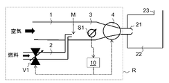
図1は、ガスバーナーを大幅に概略化して示した図である。ガス混合物は、1つ又は複数のバーナーノズル21を通って燃焼室22に入る。煙道ガスは、排気管23を通って燃焼室を出る。
(Adjustment of mixing ratio using one sensor)
FIG. 1 shows a highly schematic representation of a gas burner. The gas mixture enters
ガス混合物の供給は、調節装置Rによって調節される。調節装置Rは空気導管1と燃料ガス導管2とを備え、空気導管1を通って空気が調節装置に入り、燃料ガス導管2を通って燃料ガス、例えば天然ガスが調節装置に入る。燃料ガス導管2内の燃料ガスの流れは、燃料制御弁V1の形態の調整装置によって調節される。混合領域Mにおいて、燃料ガス導管2は空気導管1へと開口しており、燃料ガスと空気からなる燃焼ガス混合物を生成する。空気導管1の、燃料ガス流の空気流への噴射点から下流側にある部分は、ガス混合物のための共通導管3と見なすことができる。ガス混合物を共通導管3からバーナーノズル21へと運ぶために、共通導管3の下流端にファン4が配置されている。
The supply of the gas mixture is regulated by the regulator R. The regulator R comprises an
ガス混合物の1つ又は複数の熱パラメータを決定するための第1のセンサS1は、センサS1がガス混合物に曝されるように、共通導管3の、混合領域Mの下流側且つファン4の上流側に配置される。有利には、センサS1は、共通導管3内のガス混合物の指向された流れ(directed flow)がセンサS1を直接通過しないように配置及び/又は構成される。例えば、センサS1は、共通導管3の側壁で、行き止まりになっている凹部に収容されてもよい。加えて又はこれに代えて、センサS1を、共通導管3とセンサS1との間でガスの拡散による交換のみを可能にする透過膜によって保護してもよく、これによりセンサS1に向けられたガス混合物の流れを防ぐ。
A first sensor S1 for determining one or more thermal parameters of the gas mixture is located in the
制御装置10は、第1のセンサS1からセンサ信号を受信する。このセンサ信号に基づいて、制御装置10は、燃料制御弁V1の開口度を調整するための制御信号を導出する。制御装置10は、さらに、ファン4を作動させる電力を調整する。
The
図2は、調節装置の別の実施形態を示す。この実施形態では、第1のセンサS1は、ファン4に一体化されている、すなわち、ファン4のハウジング内に収容されている。他の実施形態では、センサS1をファン4の下流側に配置することもできる。
FIG. 2 shows another embodiment of the adjustment device. In this embodiment, the first sensor S1 is integrated into the
図3は、図1又は図2に示されるような調節装置を使用して、第1の実施形態によるガス混合物の混合比を調節する方法を示す。 FIG. 3 shows a method of adjusting the mixing ratio of a gas mixture according to the first embodiment using an adjusting device such as that shown in FIG. 1 or FIG.
ステップ101において、燃料制御弁V1が閉じられ、ファン4を既定のファンの出力又はファン回転速度で作動させて、空気導管1及び共通導管3を通る空気の流れを引き起こす。
At
ステップ102において、第1のセンサS1が作動され、共通導管3を通過している空気の熱伝導率λair及び熱拡散率Dairが測定される。
In
ステップ103において、燃料制御弁V1が開かれ、空気流に燃料ガス流が入れられる。
In
ステップ104において、第1のセンサS1が作動され、得られたガス混合物の熱伝導率λmix及び熱拡散率Dmixが測定される。
In
ステップ105において、ガス混合物の混合比xが求められる。これは次のように求めることができる。本議論の目的のために、混合比xは、ガス混合物中の燃料ガスのv/v濃度として定義することができる。この定義を用いると、熱伝導率λmixは、適切な近似で(to a good approximation)、混合比xに線形従属する:
λmix=x・λfuel+(1-x)・λair 式(1)
In
λ mix = x λ fuel + (1-x) λ air formula (1)
式(1)をxについて解くと次のようになる:
x=(λmix-λair)/(λfuel-λair) 式(2)
Solving equation (1) for x yields:
x = (λ mix - λ air )/(λ fuel - λ air ) Equation (2)
λairとλmixの値は、ステップ102と104の測定から分かる。λfuelの値は直接には測定されないが、代表的な燃料ガス(例えば、「平均的な」天然ガス)に対する既定値を使用することができる。
The values of λ air and λ mix are known from the measurements in
熱拡散率は式(2)に入らない、つまり、熱拡散率は冗長な情報を提供することに注意しなければならない。熱拡散率Dmixも、適切な近似で、混合比xに線形従属する:
Dmix=x・Dfuel+(1-x)・Dair 式(3)
Note that thermal diffusivity does not enter equation (2), ie thermal diffusivity provides redundant information. The thermal diffusivity D mix is also, to a good approximation, linearly dependent on the mixing ratio x:
D mix = x D fuel + (1-x) D air formula (3)
この関係を使用して、ステップ106にて、式(2)によって求められた混合比xの値を用いて、熱拡散率Dmixの測定値が、式(3)によって計算された期待値に一致するかどうかをチェックすることによって、整合性チェックが行われる。整合性チェックには、代表的な燃料ガスのDfuelの既定値を使用することができる。Dmixの測定値と計算値の差ΔDが閾値ΔDmaxを超えると、制御装置10からエラーメッセージが出力され、安全対策として燃料制御弁V1が閉じられる。
Using this relationship, in
ステップ107において、制御アルゴリズムが実行され、このとき、センサS1のセンサ信号から求めた実際の混合比(制御アルゴリズムのプロセス変数)が、所望する混合比(制御アルゴリズムの設定ポイント)と比較され、それに応じて、ガス制御弁V1の新しい設定が決定される。任意の公知の制御アルゴリズム、例えば、よく知られている比例-積分-微分(PID)制御アルゴリズムを用いることができる。
In
その後、プロセスはステップ103にループバックし、そこで燃料制御弁V1が新しい設定に従って操作される。 The process then loops back to step 103 where fuel control valve V1 is operated according to the new setting.
(センサS1を用いた空気圧の決定)
ステップ102で測定された共通導管3内の空気の熱伝導率λair及び熱拡散率Dairの値を使用して、空気の密度ρair及び/又は圧力pairを以下のように求めることができる。ガスの熱拡散率Dは、次の式によって、その熱伝導率λ、その密度ρ及びその比熱容量cpに関連付けられる:
D=λ/(cpρ) 式(4)
熱伝導率と熱拡散率の両方が分かっている場合、体積比熱容量(volumetric specific heat capacity)cpρは式(4)を用いて容易に計算できる。ガスの比熱容量cpが別の情報源から分かっている場合、密度ρについて上記の方程式を解くことができる。ガスの温度Tもわかっている場合は、関係式p=ρRspecTによってガス圧力pを容易に求めることができ、ここで、Rspecはガスの比気体定数(specific gas constant)である。
(Determination of air pressure using sensor S1)
Using the values of thermal conductivity λ air and thermal diffusivity D air in the
D=λ/(c p ρ) Equation (4)
If both the thermal conductivity and thermal diffusivity are known, the volumetric specific heat capacity c p ρ can be easily calculated using equation (4). If the specific heat capacity c p of the gas is known from another source, the above equation can be solved for the density ρ. If the temperature T of the gas is also known, the gas pressure p can be easily determined by the relationship p=ρR spec T, where R spec is the specific gas constant of the gas.
乾燥空気の定圧比熱容量(isobaric specific heat capacity)cpはよく知られており、標準状態付近では温度と圧力にほとんど依存しない。乾燥空気の比気体定数Rspecもよく知られている。従って、ステップ102で空気の熱伝導率λairと熱拡散率Dairを測定することにより、空気の密度ρairを求めることが可能である。温度Tairも分かる場合は、さらに空気圧pairを求めることができる。温度Tairを求めるために、第1のセンサS1を絶対温度モードで操作するか、又は、別の温度センサ(図示せず)を空気導管1及び/又は共通導管3に設けてもよい。当該技術分野でよく知られているように、湿った空気に対しては適切な補正を適用することができる。そのような補正を適用できるようにするために、空気の相対湿度を測定するための湿度センサを、空気導管1及び/又は共通導管3に設けてもよい。
The isobaric specific heat capacity c p of dry air is well known and almost independent of temperature and pressure near standard conditions. The specific gas constant R spec of dry air is also well known. Therefore, by measuring the thermal conductivity λ air and thermal diffusivity D air of air in
(センサS1を用いてのファンの誤動作又は閉塞の検出)
このように求めた空気密度ρair又は空気圧pairは、さらなる診断パラメータとして用いることができる。例えば、空気密度ρair又は空気圧pairは、ファン4の誤動作、あるいは、空気導管1又は共通導管3の閉塞を検出するために用いることができる。
(Detection of fan malfunction or blockage using sensor S1)
The air density ρ air or air pressure p air determined in this way can be used as a further diagnostic parameter. For example, air density ρ air or air pressure p air can be used to detect malfunction of
このような誤動作や閉塞を検出するための考え得る方法を図4に示す。ステップ201において、燃料制御弁V1が閉じられる。ステップ202において、ファン4に供給される電力は、何らかのゼロでない値に設定される。その結果、空気が共通導管3を通過する。ステップ203において、このファンの出力での空気の熱伝導率λair、熱拡散率Dair及び気体温度Tairは、第1のセンサS1を用いて測定される。ステップ204において、空気圧pair又は空気密度は、上記のように、これらのパラメータから求められる。この手順は、所定の数の異なるファンの出力に対して体系的に繰り返される。その後、空気圧pair又は空気密度のファンの出力への依存度を、予想される依存度と比較して、閉塞パラメータBを得る。特に、図1及び図2の構成では、ファン4によって吸引効果が発生するため、ファンの出力の増加に伴い、空気圧pairがわずかに低下すると予想される。空気圧が予想よりも大幅に低下する場合、これはセンサS1の上流側にある空気導管1又は共通導管3での閉塞を示す。空気圧が全く下がらない場合、これはファン4の下流側での閉塞、又は、ファン4の誤作動を示す。閉塞パラメータは、測定データから導出される。例えば、閉塞パラメータBは、測定された空気圧pair対関連するファンの出力に対応するデータ対の線形回帰分析によって得られた回帰直線の傾き(the slope of a best-fit line)に相当するとしてもよい。
A possible method for detecting such malfunctions or blockages is shown in FIG. At
(スワール部材)
図5の実施形態では、任意選択のスワール部材5が、混合領域Mの下流側の共通導管1及び/又は混合領域Mに設けられている。スワール部材は、空気-燃料混合物の均一性を改善するために、乱流を生み出すように作用する。
(Swirl member)
5, an
(空気導管及び/又は燃料導管でのさらなるセンサの使用;スワール部材)
空気導管1及び/又は燃料導管2に、さらなるセンサを設けることができる。これも図5に示す。この実施例では、混合領域Mの上流側の空気導管1に第2のセンサS2が設けられている。加えて又はこれに代えて、燃料導管2の、燃料制御弁V1の下流側且つ混合領域Mの上流側に、第3のセンサS3が設けられている。第1のセンサS1と同様に、第2及び/又は第3のセンサS2,S3もまた、有利には、各センサをそれぞれの導管の壁の行き止まりになっている凹部に配置することによって、及び/又は、各センサをガス透過膜で保護することによって、それぞれのガス流に直接曝されることから保護される。
(Use of additional sensors in air and/or fuel conduits; swirl members)
Further sensors can be provided in the
図6は、センサS1並びにセンサS2及びS3を用いて混合比を調節することが可能な方法を示す。 FIG. 6 shows how the mixing ratio can be adjusted using sensor S1 and sensors S2 and S3.
ステップ301において、燃料制御弁V1を操作して、燃料ガスのゼロでない流れを提供する。
In
ステップ302において、センサS1を作動して、混合領域Mの下流側の共通導管3内のガス混合物の熱伝導率λmix、熱拡散率Dmix及び温度Tmixを測定する。
In
ステップ303において、センサS2を作動して、混合領域Mの上流側の空気導管1内の空気の熱伝導率λair、熱拡散率Dair、温度Tairを測定する。
In
ステップ304において、これらの量から空気圧pairを求める。センサS2の信号から求めた空気圧pair又は空気密度は、追加の診断パラメータとして使用できる。特に、空気圧pair又は空気密度を用いて、ファン4の閉塞又は誤動作を検出することができる。例えば、空気圧又は密度を、調節装置の作動中に恒久的又は定期的に監視することができる。一定のファンの出力でファンを作動させている間の、空気圧又は密度の変化は、閉塞又はファンの誤動作を示すであろう。図4の実施形態とは対照的に、センサS2の信号から空気圧又は密度を求めることは、調節装置の通常動作中であっても可能であるが、図4と関連して上記で説明した上記の実施形態では、閉塞及び誤動作を、燃料供給を停止している間しか検出できない。
At
ステップ305において、センサS3を作動して、燃料制御弁V1の下流側且つ混合領域Mの上流側の燃料導管2内の燃料ガスの熱伝導率λfuel、熱拡散率Dfuel及び温度Tfuelを測定する。
In
ステップ306において、混合比xは、式(3)に基づき、センサS1によって測定されたλmix、センサS2によって測定されたλair、及びセンサS3によって測定されたλfuelの値を使用して求められる。センサS2を省略した場合、図3と関連して説明したように、代わりに、ガス制御バルブを閉じている間にセンサS1によって測定されたλairの値を用いることができる。センサS3を省略した場合、典型的な燃料ガスに対して予め決まっているλfuelの値を用いることができる。
In
ステップ307において、いくつかの診断チェックが実行される。特に、図3と関連して既に説明したように、熱拡散率Dmixの測定値が、式(2)によって求めた混合比xの値を用いて、式(3)によって計算された期待値に一致するかどうかを判断することによって、第1の整合性チェックが実行される。図3の実施形態とは対照的に、センサS2及びS3によって測定された、酸素キャリアガス及び燃料ガスの熱拡散率の実際の値を、この整合性チェックのために使用することができる。Dmixの測定値と計算値の差ΔDの絶対値が閾値ΔDmaxを超えると、制御装置10からエラーメッセージが出力され、安全対策として燃料制御弁V1が閉じられる。センサS1とS2によってそれぞれ測定された温度TmixとTairが異なるかどうかをチェックすることによって、第2の整合性チェックが実行される。温度差ΔT=Tmix-Tairの絶対値が閾値ΔTmaxを超えると、制御装置10によって再びエラーメッセージが出力され、安全対策として燃料制御弁V1が閉じられる。この整合性チェックは、センサS1及びS2が、共通のプリント回路基板などの熱伝導性のある共通の担体に取り付けられている場合に特に効き目がある。上述のように、センサS2の信号から求めた空気圧pairがファンの閉塞又は誤動作を示しているかどうかをチェックすることによって、第3の整合性チェックが実行される。ファンの閉塞又は誤動作を示していれば、やはり、制御装置10からエラーメッセージが出力され、安全対策として燃料制御弁V1が閉じられる。
At
ステップ308において、図3の実施形態におけるステップ107と関連して上記で説明したように、燃料制御弁V1のための制御信号を導出するために制御アルゴリズムが実行される。
At
λairの値を求めるためにセンサS2を用いる場合、空気の相対湿度など、センサS1とS2の両方の出力に影響を与える任意のパラメータの影響は、差分λmix-λairをとる際に大部分が相殺される。これは、混合比(つまり、ガス混合物中の燃料濃度)が小さい場合特にあてはまる(true)。何故なら、この場合、どんな変化であれλairの変化は、λmixにほぼ同一の変化として現れるからである。このようにして、混合比のより精密な制御が達成されるであろう。 When using sensor S2 to determine the value of λ air , the effect of any parameter that affects the outputs of both sensors S1 and S2, such as the relative humidity of the air, is significant in taking the difference λ mix −λ air . parts are cancelled. This is especially true when the mixture ratio (ie fuel concentration in the gas mixture) is small. This is because, in this case, any change in λ air results in approximately the same change in λ mix . In this way a more precise control of the mixing ratio will be achieved.
λfuelの値を求めるためにセンサS3が使用される場合、調節装置は燃料ガスに適応できるようになる。一方で、混合比の決定には、代表的な燃料ガスに対する既定値ではなく、λfuelの実際の値を考慮する。これにより、混合比の制御の精度が向上する。他方で、λfuel、Dfuel、及びTfuelを測定し、任意選択でセンサS2によって取得した圧力pairを考慮することにより(空気導管1と燃料導管2内の圧力がほぼ等しいと仮定)、燃料ガスを精密に特性づけることが可能になる。特に、測定されたパラメータλfuel、Dfuel、Tfuelと任意選択でpairとに基づいて、最適化された燃焼が期待される最適な混合比を求め、それに応じて、制御アルゴリズムの設定ポイントを設定することが可能になる。加えて又はこれに代えて、これらのパラメータに基づいて、単位体積あたりの燃焼熱Hρ、ウォッベ指数Iw及び/又はメタン価(methane number)NMなどの、燃料ガスの燃焼パラメータを求めることが可能になる。これは、測定されたパラメータをこれらの燃焼パラメータの1つ又は複数に相関させる、経験的に求められた相関関数及び/又はルックアップテーブルを使用することによってなし得る。
If sensor S3 is used to determine the value of λfuel , the regulator will be able to adapt to the fuel gas. On the other hand, the determination of the mixture ratio takes into account the actual value of λ fuel rather than the default value for typical fuel gases. This improves the accuracy of mixing ratio control. On the other hand, by measuring λ fuel , D fuel and T fuel and optionally taking into account the pressure pair obtained by sensor S2 (assuming that the pressures in air
(流量の測定)
図7及び8に示すように、質量流量計6を使用して、空気導管1内の空気流、燃料導管2内の燃料流、又は共通導管3内のガス混合物流の、質量流量を、付加的に測定することができる。このようにして、ガスバーナーに運ばれるガス混合物の絶対火力(absolute heating power)を求めることが可能となる。質量流量を用いて、火力を調節するためにファン4を制御することができる。
(Measurement of flow rate)
As shown in FIGS. 7 and 8, a
図7の実施形態では、混合領域Mの上流側の空気導管1に質量流量計6が配置される。質量流量計6は、空気導管1内の流量制限器7と、この流量制限器7を迂回する狭いバイパス管路8とを備える。流量センサD1は、バイパス管路8を通る流量又は流速を測定し、この流量/流速は、流量制限器7を挟んだ差圧を示す。従って、流量センサDは差圧センサとして働く。前記差圧は、流量制限器7を通る質量流量を示す。
In the embodiment of FIG. 7, a
図8の実施形態では、同様に設計された質量流量計6が燃料導管2に配置されている。
In the embodiment of FIG. 8, a similarly designed
図9に示すように、空気導管1の質量流量は、混合領域Mの上流側の空気導管1に流量制限器7を配置し、流量制限器7の上流側の空気導管1と燃料導管2との間の差圧Δpを、これらの導管の間の狭いバイパス管路8を用いて測定することによって、求めることもできる。この差圧は、流量制限器7の下流側の空気導管1内の圧力pairが燃料導管2内の圧力pfuelと同じであると仮定して、流量制限器7を挟んだ圧力に相当する。
As shown in FIG. 9, the mass flow rate of the
図10に示すように、同じ意図で(in the same spirit)、混合領域Mの上流側の燃料導管2に流量制限器7を配置し、流量制限器7の上流側の燃料導管2と空気導管1との間の差圧Δpを測定することにより、燃料導管2の質量流量を求めることができる。
As shown in FIG. 10, in the same spirit, the
(センサS1,S2,S3,D1)
熱伝導率及び熱拡散率を示す熱パラメータを測定することができるセンサは、当技術分野でよく知られている。好ましくは、マイクロサーマルセンサが使用される。多くのタイプのマイクロサーマルセンサが知られており、本発明は特定のタイプのマイクロサーマルセンサに限定されない。
(Sensors S1, S2, S3, D1)
Sensors capable of measuring thermal parameters indicative of thermal conductivity and thermal diffusivity are well known in the art. Preferably, micro-thermal sensors are used. Many types of micro-thermal sensors are known and the invention is not limited to any particular type of micro-thermal sensor.
本発明に関連して使用することができる、実装可能なマイクロサーマルセンサを図11に示す。マイクロサーマルセンサは、基板31、特にシリコン基板を備える。基板31は、開口部又は凹部32を中に配備する。マイクロサーマルセンサは、この開口部又は凹部32に架かる複数の隔てられたブリッジを備える。詳細については、EP 3 367 087 A2を参照されたい。
A possible micro-thermal sensor that can be used in connection with the present invention is shown in FIG. The microthermal sensor comprises a
図11の実施例では、マイクロサーマルセンサは、加熱ブリッジ33、第1の検出ブリッジ35、及び第2の検出ブリッジ36を備え、各ブリッジは、凹部又は開口部2に架かり、基板1に固定されている。各ブリッジは、複数の誘電体層、金属層、及びポリシリコン層によって形成することができる。以下でより詳細に説明するように、金属層又はポリシリコン層は、加熱構造体及び温度センサを形成する。誘電体層は、特に、それぞれのブリッジの誘電性ベース材料として酸化シリコン及び/又は窒化シリコンの層を備えることができる。検出ブリッジ35,36は、加熱ブリッジ33を挟んで、対向する側に(opposite sides)配置される。第1の検出ブリッジ35は、加熱ブリッジ33に対して距離d1で配置され、第2の検出ブリッジ36は、加熱ブリッジ33に対して同じ距離か、又は異なる距離d2で配置される。
In the embodiment of FIG. 11, the microthermal sensor comprises a
加熱ブリッジ33は、加熱構造体34と、例えば酸化シリコンからなる誘電性ベース材料に付設された温度センサTS1とを備える。加熱構造体34と温度センサTS1は、誘電性ベース材料によって互いに電気的に絶縁されている。第1の検出ブリッジ35は、温度センサTS2を備える。同様に、第2の検出ブリッジ36は、温度センサTS3を備える。温度センサTS1は、加熱ブリッジ33の温度を測定するように調整され、温度センサTS2は、第1の検出ブリッジ35の温度を測定するように調整され、温度センサTS3は、第2の検出ブリッジ36の温度を測定するように調整される。
The
マイクロサーマルセンサは、マイクロサーマルセンサの動作を制御するための制御回路37a,37bをさらに備える。制御回路37a,37bは、基板31上の集積回路として具体化することができる。それは、加熱構造体34を駆動するための、及び温度センサTS1,TS2及びTS3からの信号を処理するための回路を含む。この目的のために、制御回路37a,37bは、相互接続回路38を介して、加熱構造体34及び温度センサTS1,TS2及びTS3に電気的に接続される。有利には、制御回路37a,37bは、CMOS技術で基板31上に集積される。CMOS回路を基板31に集積させることにより、基板へのボンディング数を減らせ、信号対雑音比を高めることができる。図11に示されているタイプの構造は、例えば、EP 2 278 308又はUS 2014/0208830に記載されているような技術を使用して構築することができる。
The micro thermal sensor further comprises
(熱伝導率及び熱拡散率の決定)
図11のマイクロサーマルセンサを使用して、センサが曝されるガスの熱伝導率λと体積比熱容量cpρを、EP 3 367 087 A2に記載される方法で求めることができる。
(Determination of thermal conductivity and thermal diffusivity)
Using the microthermal sensor of FIG. 11, the thermal conductivity λ and the volumetric specific heat capacity c p ρ of the gas to which the sensor is exposed can be determined by the methods described in
特に、熱伝導率λは、加熱構造体34を作動させ、温度センサTS1によって測定することができる定常状態温度まで加熱して、温度センサTS2及び/又はTS3における定常状態温度を測定することによって求めることができる。センサTS2及びTS3における定常状態温度は、ガスの熱伝導率に依存する。
In particular, the thermal conductivity λ is determined by activating the
体積比熱容量cpρは、複数の異なる温度でガスの熱伝導率を測定し、熱伝導率の温度依存性の係数を求め、フィッティング関数(fitting function)を使用してこれらの係数から体積比熱容量を導出することによって求めることができる。詳細については、EP 3 367 087 A2を参照されたい。
The volumetric specific heat capacity c p ρ is obtained by measuring the thermal conductivity of a gas at a number of different temperatures, determining the coefficients of the temperature dependence of the thermal conductivity, and using a fitting function to convert these coefficients to the volume ratio It can be obtained by deriving the heat capacity. See
一旦、熱伝導率λと体積比熱容量cpρが分かれば、熱拡散率Dは、式D=λ/(cpρ)(式(4))を用いて容易に求めることができる。 Once the thermal conductivity λ and the volumetric specific heat capacity c p ρ are known, the thermal diffusivity D can be easily determined using the equation D=λ/(c p ρ) (equation (4)).
さらに、温度センサTS1,TS2及びTS3のそれぞれは、ガスの絶対温度を求めるために、加熱力がない状態で作動させることができる。 Furthermore, each of the temperature sensors TS1, TS2 and TS3 can be operated without heating power to determine the absolute temperature of the gas.
ガスとそれぞれのブリッジの間の熱転移を排除するために、異なる距離d1及びd2を用いて差分測定を実行できる。一例として、比(TS1-TS2)/THは、熱伝導率λの尺度としてとらえることができ、ここで、TS1は、第1の検出ブリッジ35での測定温度を示し、TS2は、第2の検出ブリッジ36での測定温度を示し、THは、加熱ブリッジ33での加熱温度を示す。
Differential measurements can be performed using different distances d1 and d2 to eliminate heat transfer between the gas and each bridge. As an example, the ratio (T S1 −T S2 )/T H can be taken as a measure of the thermal conductivity λ, where T S1 denotes the measured temperature at the
マイクロサーマルセンサを使用した、ガスの熱伝導率及び熱拡散率を示す熱パラメータを求める他の方法が当技術分野で知られており、本発明は特定の方法に限定されない。 Other methods of determining thermal parameters indicative of thermal conductivity and diffusivity of gases are known in the art using micro-thermal sensors, and the invention is not limited to any particular method.
例えば、US 4,944,035 B1は、マイクロサーマルセンサを使用して、対象の流体の熱伝導率λ及び比熱容量cpを求める方法を開示する。マイクロサーマルセンサは、対象の流体によって結合される抵抗ヒーターと温度センサを備える。過渡変化と、実質的に定常状態温度の両方が温度センサで発生するような、レベル及び継続時間を有する電気エネルギーのパルスが、ヒーターに加えられる。対象の流体の熱伝導率は、定常状態のセンサ温度での温度センサ出力と熱伝導率との間の既知の関係に基づいて求められる。比熱容量は、熱伝導率、センサでの過渡温度変化時の温度センサ出力の変化率、及び比熱容量の間の既知の関係に基づいて求められる。 For example, US 4,944,035 B1 discloses a method for determining the thermal conductivity λ and the specific heat capacity c p of a fluid of interest using microthermal sensors. A micro-thermal sensor comprises a resistive heater and a temperature sensor coupled by the fluid of interest. A pulse of electrical energy having a level and duration such that both a transient change and a substantially steady state temperature are produced at the temperature sensor is applied to the heater. The thermal conductivity of the fluid of interest is determined based on the known relationship between temperature sensor output and thermal conductivity at steady state sensor temperature. Specific heat capacity is determined based on the known relationship between thermal conductivity, rate of change of temperature sensor output during a transient temperature change at the sensor, and specific heat capacity.
US 6,019,505 B1は、マイクロサーマルセンサを使用した、対象の流体の熱伝導率、熱拡散率、及び比熱容量を決定するための方法を開示する。マイクロサーマルセンサは、ヒーターと、間隔を隔てた温度センサとを備え、両方とも対象の流体に結合される。時間可変入力信号がヒーターエレメントに提供され、ヒーターエレメントが周囲の流体を加熱する。選択した入力AC信号と出力AC信号との間の可変位相又はタイムラグが測定され、ここから、熱伝導率、熱拡散率、及び比熱容量が求められる。 US 6,019,505 B1 discloses a method for determining the thermal conductivity, thermal diffusivity and specific heat capacity of a fluid of interest using microthermal sensors. A micro-thermal sensor includes a heater and a spaced-apart temperature sensor, both coupled to the fluid of interest. A time-varying input signal is provided to the heater element, causing the heater element to heat the surrounding fluid. A variable phase or time lag between selected input and output AC signals is measured, from which thermal conductivity, thermal diffusivity, and specific heat capacity are determined.
(制御装置)
デジタル制御装置500の簡略化された非常に概略的なブロック図を図12に示す。制御装置は、プロセッサ(CPU)μP、揮発性(RAM)メモリ52、及び不揮発性(例えば、フラッシュROM)メモリ53、を備える。プロセッサμPは、データバス51を介してメモリデバイス52,53と通信する。不揮発性メモリ53は、とりわけ、様々なセンサのための較正データのセットを複数記憶する。図12には、ルックアップテーブルLUT1,LUT2の形で、較正データ54,55の、例示的なセットが2つだけ示されている。ルックアップテーブルは、例えば、マイクロサーマルセンサの温度センサによって測定された温度の値を、熱伝導率や熱拡散率などの熱パラメータに関連付けることができる。不揮発性メモリ53はさらに、プロセッサμPで実行するための機械実行可能(machine-executable)プログラム56を格納する。デバイスインターフェースIFを介して、制御装置は、様々なセンサS1,S2,S3及び/又はD1と通信する。デバイスインターフェースはさらに、ファン4及び燃料制御バルブV1と、並びに、キーボード及び/又はマウス、LCDスクリーンなどの入力/出力デバイスI/Oと通信するためのインターフェースを備える。
(Control device)
A simplified highly schematic block diagram of a digital controller 500 is shown in FIG. The controller comprises a processor (CPU) μP, volatile (RAM)
(変形)
本発明の範囲を逸脱することなく、上記実施形態に対して多くの変形が可能である。
(deformation)
Many variations are possible to the above embodiments without departing from the scope of the invention.
特に、空気導管1は、空気以外の別の酸素キャリアガスの流れを運ぶことができる。例えば、排気ガスの再循環を実施する実施形態では、空気導管1は、空気と煙道(排気)ガスとの混合物を運ぶことができる。
In particular, the
燃料ガスは、任意の可燃性ガスにすることができる。好ましくは、燃料ガスは天然ガスである。 The fuel gas can be any combustible gas. Preferably, the fuel gas is natural gas.
酸素キャリアガスと燃料ガスとの混合は、図示とは異なる方法で実施することができる。例えば、燃料ガスは、任意に配置することのできる複数の噴射ノズルを通して酸素キャリアガス流に噴射してもよく、あるいは、専用のミキサーを使用して混合することもできる。 The mixing of the oxygen carrier gas and the fuel gas can be done in different ways than shown. For example, the fuel gas may be injected into the oxygen carrier gas stream through a plurality of arbitrarily positioned injection nozzles, or it may be mixed using a dedicated mixer.
本明細書に開示した調節装置は、ガスバーナーに対してだけでなく、内燃機関(ガスモーター又はガスタービン)等の、燃料ガスと酸素キャリアガスの混合物が必要とされる他の用途にも使用することができる。 The regulator disclosed herein can be used not only for gas burners, but also for other applications where a mixture of fuel gas and oxygen carrier gas is required, such as internal combustion engines (gas motors or gas turbines). can do.
共通導管3の下流端にファン4を配置する代わりに、別の場所にファン4を配置することが可能である。例えば、ファン4を、空気導管1の上流端に配置してもよい。ガス流を生成することのできる任意のタイプのファン、例えば、当該技術分野でよく知られているラジアルファン又はアキシャルファンを使用してもよい。制御装置10は、燃料制御弁V1を制御するだけでなく、ファンの出力を制御するようにも構成してもよい。空気導管1を通る酸素キャリアガスの流れを付加的に調節するために、空気弁又は空気フラップが空気導管内に存在してもよく、制御装置10を、空気弁又は空気フラップをも制御するように構成してもよい。
Instead of placing the
上記の実施例において、センサS1,S2,S3は熱伝導率と熱拡散率を測定する。しかしながら、センサによって測定される熱パラメータから熱伝導率及び/又は熱拡散率を導き出すことが可能である限り、センサが熱伝導率及び熱拡散率に関連する他の熱パラメータを測定することも可能である。上記の実施例では、混合比は熱伝導率の測定に基づいて制御される。しかしながら、熱伝導率及び/又は熱拡散率に関連する任意の他の熱パラメータに基づいて混合比の制御を行うことが可能である。 In the above example, the sensors S1, S2, S3 measure thermal conductivity and thermal diffusivity. However, it is also possible for the sensor to measure other thermal parameters related to thermal conductivity and thermal diffusivity, as long as thermal conductivity and/or thermal diffusivity can be derived from the thermal parameters measured by the sensor. is. In the above examples, the mixing ratio is controlled based on thermal conductivity measurements. However, it is possible to base the control of the mixing ratio on any other thermal parameter related to thermal conductivity and/or thermal diffusivity.
上記の実施例では、混合比xは、測定された熱パラメータから明示的に求められ、燃料及び/又は空気の流れを調節するための制御アルゴリズムのプロセス変数として使用される。しかしながら、これは必須ではない。例えば、制御アルゴリズムのプロセス変数は、直接的に、センサS1によって測定される熱パラメータの1つ、又はそこから導出される量、例えば熱伝導率の差分λmix-λairであってもよい。このとき、制御アルゴリズムの設定ポイントはこの差分の所望する値となる。この設定ポイントは、λfuel,Dfuel,Tfuel,λair,pair,Tair及びTmixのうちの1つ又は複数から事前に決定できるか、又は計算できる。 In the above example, the mixture ratio x is explicitly determined from the measured thermal parameters and used as a process variable in the control algorithm for adjusting the fuel and/or air flow. However, this is not required. For example, the process variable of the control algorithm may directly be one of the thermal parameters measured by sensor S1, or a quantity derived therefrom, eg, the thermal conductivity difference λ mix −λ air . The set point of the control algorithm is then the desired value of this difference. This setpoint can be predetermined or calculated from one or more of λ fuel , D fuel , T fuel , λ air , pair , T air and T mix .
調節装置は、2つのガスからなる、まったく異なる種類の二成分の混合物を調節するために使用できる。これらのガスは、キャリアガス及び機能性ガスと呼ぶことができる。従って、上記の実施形態の空気導管は、より一般的には、キャリアガス用の第1の導管の一例と見なすことができ、燃料導管は、機能性ガス用の第2の導管の一例と見なすことができる。例えば、調節装置は、酸素キャリアガスと、ガス状麻酔薬などの医療用ガスとの混合物を調節するように構成することができる。 The regulator can be used to regulate very different types of binary mixtures of two gases. These gases can be referred to as carrier gases and functional gases. Thus, the air conduits of the above embodiments can be viewed more generally as an example of a first conduit for the carrier gas and the fuel conduit as an example of a second conduit for the functional gas. be able to. For example, the regulator can be configured to regulate a mixture of oxygen carrier gas and a medical gas such as a gaseous anesthetic.
当業者には、本発明の範囲を逸脱することなく様々な他の変更が可能であることが理解されるであろう。 Those skilled in the art will appreciate that various other modifications are possible without departing from the scope of the invention.
Claims (44)
前記第1のガスの流れを運ぶための第1の導管(1);
前記第2のガスの流れを運ぶための導管であって、前記ガス混合物を生成するために、前記第1の導管(1)とともに、混合領域(M)で共通導管(3)に開口する第2の導管(2);
前記ガス混合物の混合比(x)を調整するための調整装置(V1);及び
前記調整装置(V1)に対する制御信号を導出するように構成される制御装置(10)、を備える調節装置において、
前記調節装置は、前記混合領域(M)の下流側の前記ガス混合物の少なくとも1つの熱パラメータを測定するように構成される第1のセンサ(S1)を備え、及び
前記制御装置(10)は、前記第1のセンサ(S1)から、前記ガス混合物の前記少なくとも1つの熱パラメータを示すセンサ信号を受信し、前記少なくとも1つの熱パラメータに基づいて前記調整装置に対する制御信号を導出するように構成されることを特徴とする調節装置。 An adjustment device for adjusting the mixing ratio (x) of a gas mixture comprising a first gas and a second gas, comprising:
a first conduit (1) for carrying said first gas flow;
a conduit for carrying said second gas flow, said conduit opening together with said first conduit (1) into a common conduit (3) in a mixing zone (M) for producing said gas mixture; two conduits (2);
in a regulating device comprising a regulating device (V1) for regulating the mixing ratio (x) of said gas mixture; and a control device (10) adapted to derive a control signal for said regulating device (V1),
The regulator device comprises a first sensor (S1) configured to measure at least one thermal parameter of the gas mixture downstream of the mixing region (M), and the controller (10) , configured to receive from said first sensor (S1) a sensor signal indicative of said at least one thermal parameter of said gas mixture and to derive a control signal for said regulator based on said at least one thermal parameter. An adjustment device, characterized in that:
前記第1のガスは、自然の空気、酸素富化空気、酸素と1つ又は複数の不活性ガスの混合物、又は、純粋な酸素ガスであり、前記第2のガスは、医療用ガスである、請求項4に記載の調節装置。The first gas is natural air, oxygen-enriched air, a mixture of oxygen and one or more inert gases, or pure oxygen gas, and the second gas is a medical gas. 5. The adjusting device according to claim 4.
前記制御装置(10)は、前記少なくとも2つの熱パラメータを考慮するように構成されている、請求項1~6のいずれかに記載の調節装置。 The first sensor (S1) is configured to measure at least two thermal parameters of the gas mixture, the two thermal parameters taken together being the thermal conductivity (λ mix ) of the gas mixture and Regulating device according to any of the preceding claims, wherein it exhibits a thermal diffusivity (D mix ) and said controller (10) is arranged to take into account said at least two thermal parameters.
前記調整装置を、前記第1のガスの流れがゼロでない流量を有すると同時に、前記第2のガスの流れが遮断される基準状態に設定するステップ;
前記第1のセンサ(S1)からセンサ信号を受信し、該センサ信号は前記基準状態における前記少なくとも2つの熱パラメータを示すステップ;及び
前記基準状態における前記少なくとも2つの熱パラメータに基づいて、前記基準状態における前記第1のガスの密度又は圧力を示す圧力パラメータ(pair)を求めるステップ。 9. Regulating device according to claim 7 or 8 , wherein the control device (10) is arranged to perform the following steps:
setting the regulator to a reference state in which the first gas flow has a non-zero flow rate while the second gas flow is blocked;
receiving a sensor signal from said first sensor (S1), said sensor signal being indicative of said at least two thermal parameters in said reference state; and based on said at least two thermal parameters in said reference state, said reference Determining a pressure parameter (p air ) indicative of the density or pressure of said first gas at the state.
前記調整装置を、前記第1のガスの流れがゼロでない流量を有すると同時に、前記第2のガスの流れが遮断される基準状態に設定するステップ;
前記第1のセンサ(S1)からセンサ信号を受信し、該センサ信号は前記基準状態における前記第1のガスの少なくとも1つの熱パラメータを示すステップ;
前記調整装置を、前記第2のガスの流れ及び前記第1のガスの流れの両方がゼロでない流量を有する作動状態に設定するステップ;
前記第1のセンサ(S1)からセンサ信号を受信し、該センサ信号は前記作動状態における前記ガス混合物の少なくとも1つの熱パラメータを示すステップ;及び
前記作動状態における前記ガス混合物の前記少なくとも1つの熱パラメータと、前記基準状態における前記第1のガスの前記少なくとも1つの熱パラメータとの比較に基づいて前記制御信号を導出するステップ。 Regulating device according to any of the preceding claims, wherein the control device (10) is arranged to perform the following steps:
setting the regulator to a reference state in which the first gas flow has a non-zero flow rate while the second gas flow is blocked;
receiving a sensor signal from said first sensor (S1), said sensor signal indicative of at least one thermal parameter of said first gas in said reference state;
setting the regulator to an operating state in which both the second gas flow and the first gas flow have non-zero flow rates;
receiving a sensor signal from said first sensor (S1), said sensor signal being indicative of at least one thermal parameter of said gas mixture in said operating state; and said at least one thermal of said gas mixture in said operating state. deriving said control signal based on a comparison of a parameter with said at least one thermal parameter of said first gas in said reference state.
前記第2のガスの流れが遮断されている間に、前記ファン(4)を複数の異なる出力レベルで作動させるステップ;
各出力レベルに対して、前記第1のセンサ(S1)から受信した前記センサ信号に基づいて圧力パラメータ(pair)を求め、該圧力パラメータ(pair)は前記出力レベルでの前記第1のガスの密度又は圧力を示すステップ;及び
さまざまな出力レベルでの前記圧力パラメータ(pair)に基づいて、閉塞又はファンの誤動作が発生しているかどうかを示す閉塞信号(B)を導出するステップ。 13. Regulating device according to claim 11 or 12 , wherein the control device (10) is arranged to perform the following steps:
operating said fan (4) at a plurality of different power levels while said second gas flow is interrupted;
For each power level, a pressure parameter (pair) is determined based on said sensor signal received from said first sensor (S1), said pressure parameter (pair) being the value of said first gas at said power level. indicating the density or pressure; and based on said pressure parameter (pair) at various power levels, deriving an occlusion signal (B) indicating whether an occlusion or fan malfunction has occurred.
前記制御装置(10)は、前記第2のセンサ(S2)から、前記第1のガスの前記少なくとも1つの熱パラメータを示すセンサ信号を受信し、前記第1及び第2のセンサ(S1,S2)の両方から受信した前記センサ信号に基づいて前記制御信号を導出するように構成されている、請求項1~14のいずれかに記載の調節装置。 further comprising a second sensor (S2), the second sensor (S2) configured to measure at least one thermal parameter of the first gas;
Said control device (10) receives from said second sensor (S2) a sensor signal indicative of said at least one thermal parameter of said first gas; ), adapted to derive the control signal on the basis of the sensor signal received from both.
前記制御装置は、前記第2のセンサ(S2)によって測定される前記少なくとも2つの熱パラメータに基づいて、前記第1のガスの密度又は圧力を示す酸素キャリア圧力パラメータ(pair)を導出するように構成されている、請求項15又は16に記載の調節装置。 Said second sensor (S2) is configured to measure at least two thermal parameters, said at least two thermal parameters measured by said second sensor (S2) taken together being said first the thermal conductivity (λ air ) and the thermal diffusivity (D air ) of the gas of the 17. A regulator according to claim 15 or 16 , adapted to derive an oxygen carrier pressure parameter ( pair ) indicative of the density or pressure of the first gas.
前記第2のセンサ(S2)は、少なくとも2つの熱パラメータを測定するように構成され、前記第2のセンサ(S2)によって測定される前記少なくとも2つの熱パラメータは一緒になって、前記第1のガスの熱伝導率(λair)及び熱拡散率(Dair)を示し、
前記制御装置は、前記第1及び第2のセンサ(S1,S2)によって測定される前記熱パラメータの1つの比較に基づいて前記制御信号を導出し、且つ、前記第1及び第2のセンサ(S1,S2)によって測定される前記少なくとも2つの熱パラメータの他の1つの比較に基づいて整合性チェックを行うように構成されている、請求項15~17のいずれかに記載の調節装置。 Said first sensor (S1) is configured to measure at least two thermal parameters, said at least two thermal parameters measured by said first sensor (S1) taken together to form a showing thermal conductivity (λ mix ) and thermal diffusivity (D mix ),
Said second sensor (S2) is configured to measure at least two thermal parameters, said at least two thermal parameters measured by said second sensor (S2) taken together being said first shows the thermal conductivity (λ air ) and thermal diffusivity (D air ) of the gas of
The controller derives the control signal based on a comparison of one of the thermal parameters measured by the first and second sensors (S1, S2); 18. Regulating device according to any one of claims 15 to 17 , arranged to perform a consistency check based on a comparison of another one of said at least two thermal parameters measured by S1, S2).
前記第2のセンサ(S2)は、前記第1のガスの温度(Tair)を測定するように構成され、及び
前記制御装置は、前記ガス混合物と前記第1のガスの温度(Tmix,Tair)の比較に基づいて整合性チェックを実行するように構成されている、請求項15~18のいずれかに記載の調節装置。 said first sensor (S1) is arranged to measure the temperature (T mix ) of said gas mixture;
The second sensor (S2) is configured to measure the temperature of the first gas (T air ), and the controller determines the temperature of the gas mixture and the first gas (T mix , 19. Adjusting device according to any one of claims 15 to 18 , adapted to perform a consistency check based on a comparison of T air ).
前記制御装置(10)は、前記第3のセンサ(S3)から、前記第2のガスの前記少なくとも1つの熱パラメータを示すセンサ信号を受信し、且つ、前記第1及び第3のセンサ(S1,S3)の両方から受信した前記センサ信号に基づいて前記制御信号を導出するように構成されている、請求項1~19のいずれかに記載の調節装置。 further comprising a third sensor (S3), the third sensor (S3) configured to measure at least one thermal parameter of the second gas;
Said controller (10) receives from said third sensor (S3) a sensor signal indicative of said at least one thermal parameter of said second gas, and said first and third sensors (S1 20. The adjustment device according to any of the preceding claims, arranged to derive said control signal based on said sensor signals received from both of said control devices , S3).
前記制御装置(10)は、前記第1及び/又は第2の質量流量計(F1,F2)からの質量流量信号に基づいて、前記第1又は第2の導管(1;2)内の質量流量を示す質量流量パラメータを求めるように構成されている、請求項1~21のいずれかに記載の調節装置。 further comprising a first mass flow meter (F1) in said first conduit (1) and/or a second mass flow meter (F2) in said second conduit (2);
The controller (10) controls the mass flow in the first or second conduit (1;2) based on mass flow signals from the first and/or second mass flowmeters (F1, F2). A regulator according to any preceding claim, arranged to determine a mass flow parameter indicative of the flow rate.
前記流量制限器(6;7)の上流側の、前記第1及び第2の導管(1,2)の間の差圧を求めるように構成された差圧センサ(D1)をさらに備え、
前記制御装置(10)は、前記差圧センサ(D1)からの差圧信号に基づいて、前記第1又は第2の導管(1;2)内の質量流量を示す質量流量パラメータを求めるように構成されている、請求項1~22のいずれかに記載の調節装置。 a flow restrictor (6;7) in said first or second conduit (1;2); and said first and second conduits (1, 7) upstream of said flow restrictor (6;7); 2) further comprising a differential pressure sensor (D1) configured to determine a differential pressure between
The controller (10) determines a mass flow rate parameter indicative of the mass flow rate in the first or second conduit (1; 2) based on the differential pressure signal from the differential pressure sensor (D1). 23. The adjustment device of any of claims 1-22 , configured.
前記第1のガスの流れを生成する工程;
前記第2のガスの流れを生成する工程;
混合領域(M)で前記第1のガスと前記第2のガスの流れを混合することによって前記ガス混合物を生成する工程を含む方法において、
第1のセンサ(S1)を使用して、前記混合領域(M)の下流側の前記ガス混合物の少なくとも1つの熱パラメータを測定する工程、及び
前記少なくとも1つの熱パラメータに基づいて、前記混合比(x)を調整する工程を特徴とする方法。 A method of adjusting a mixing ratio (x) of a gas mixture comprising a first gas and a second gas, comprising:
generating said first gas flow;
generating said second gas flow;
producing said gas mixture by mixing said first gas and said second gas flow in a mixing region (M),
measuring at least one thermal parameter of said gas mixture downstream of said mixing zone (M) using a first sensor (S1); and based on said at least one thermal parameter, said mixing ratio A method comprising the step of adjusting (x).
前記第1のガスは、自然の空気、酸素富化空気、酸素と1つ又は複数の不活性ガスの混合物、又は、純粋な酸素ガスであり、前記第2のガスは、医療用ガスである、請求項26に記載の方法。The first gas is natural air, oxygen-enriched air, a mixture of oxygen and one or more inert gases, or pure oxygen gas, and the second gas is a medical gas. 27. The method of claim 26.
前記混合比(x)を調整する際に、前記ガス混合物の前記少なくとも2つの熱パラメータを考慮する、請求項24~29のいずれかに記載の方法。 At least two thermal parameters of said gas mixture are measured using said first sensor (S1), said at least two thermal parameters taken together being a thermal conductivity (λ mix ) of said gas mixture and A method according to any of claims 24 to 29 , exhibiting a thermal diffusivity (D mix ) and taking into account said at least two thermal parameters of said gas mixture when adjusting said mixing ratio (x).
前記第1のセンサ(S1)からセンサ信号を受信し、該センサ信号は前記基準状態における前記第1のガスの少なくとも2つの熱パラメータを示す工程;及び
前記基準状態における前記第1のガスの前記少なくとも2つの熱パラメータに基づいて、前記基準状態における前記第1のガスの密度又は圧力を示す圧力パラメータ(pair)を求める工程を含む、請求項30又は31に記載の方法。 creating a reference condition in which the first gas flow has a non-zero flow rate while the second gas flow is shut off;
receiving a sensor signal from said first sensor (S1), said sensor signal indicative of at least two thermal parameters of said first gas in said reference state; and said of said first gas in said reference state. 32. A method according to claim 30 or 31 , comprising determining a pressure parameter ( pair ) indicative of the density or pressure of said first gas in said reference state based on at least two thermal parameters.
前記第1のセンサ(S1)からセンサ信号を受信し、該センサ信号は、前記基準状態における前記第1のガスの少なくとも1つの熱パラメータを示す工程;
前記第2のガスの流れと前記第1のガスの流れの両方がゼロでない流量を有する作動状態を作り出す工程;
前記第1のセンサ(S1)からセンサ信号を受信し、該センサ信号は、前記作動状態における前記ガス混合物の少なくとも1つの熱パラメータを示す工程;及び
前記作動状態における前記ガス混合物の前記少なくとも1つの熱パラメータと、前記基準状態における前記第1のガスの前記少なくとも1つの熱パラメータとの比較に基づいて、前記混合比(x)を調整する工程を含む、請求項24~32のいずれかに記載の方法。 creating a reference condition in which the first gas flow has a non-zero flow rate while the second gas flow is shut off;
receiving a sensor signal from said first sensor (S1), said sensor signal being indicative of at least one thermal parameter of said first gas in said reference state;
creating operating conditions in which both the second gas flow and the first gas flow have non-zero flow rates;
receiving a sensor signal from said first sensor (S1), said sensor signal being indicative of at least one thermal parameter of said gas mixture in said operating state; and said at least one of said gas mixture in said operating state. 33. The method of any of claims 24-32 , comprising adjusting the mixing ratio (x) based on a comparison of a thermal parameter and the at least one thermal parameter of the first gas in the reference state. the method of.
各出力レベルに対して、前記第1のセンサ(S1)によって測定されたセンサ信号から圧力パラメーター(pair)を導出し、該圧力パラメーター(pair)は、前記出力レベルでの前記第1のガスの密度又は圧力を示す工程;及び
さまざまな出力レベルでの前記圧力パラメータ(pair)に基づいて、閉塞又はファンの誤動作が発生しているかどうかを示す閉塞信号(B)を導出する工程を含む、請求項34に記載の方法。 operating said fan (4) at a plurality of different power levels while said second gas flow is interrupted;
For each power level, a pressure parameter (p air ) is derived from the sensor signal measured by said first sensor (S1), said pressure parameter (p air ) being equal to said first power level at said power level. indicating gas density or pressure; and deriving an occlusion signal (B) indicating whether an occlusion or fan malfunction has occurred based on said pressure parameter (p air ) at various power levels. 35. The method of claim 34 , comprising:
前記第1のセンサ(S1)によって測定された前記ガス混合物の前記少なくとも1つの熱パラメータ及び前記第2のセンサ(S2)によって測定された前記第1のガスの前記少なくとも1つの熱パラメータに基づいて、前記混合比(x)を調整する工程を含む、請求項24~35のいずれかに記載の方法。 measuring at least one thermal parameter of said first gas upstream of said mixing zone (M) using a second sensor (S2); and adjusting said mixing ratio (x) based on said at least one thermal parameter of said gas mixture and said at least one thermal parameter of said first gas measured by said second sensor (S2) A method according to any one of claims 24 to 35 , comprising
前記第2のセンサ(S2)によって測定された前記少なくとも2つの熱パラメータに基づいて、酸素キャリア圧力パラメータ(pair)を導出し、該酸素キャリア圧力パラメータは前記第1のガスの密度又は圧力を示す工程を含む、請求項36又は37に記載の方法。 At least two thermal parameters are measured by said second sensor (S2), said at least two thermal parameters measured by said second sensor (S2) taken together to be the heat of said first gas shows conductivity (λ air ) and thermal diffusivity (D air ),
Based on said at least two thermal parameters measured by said second sensor (S2), an oxygen carrier pressure parameter (p air ) is derived, said oxygen carrier pressure parameter measuring the density or pressure of said first gas. 38. A method according to claim 36 or 37 , comprising the step of indicating.
前記第2のセンサ(S2)を使用して前記第1のガスの少なくとも2つの熱パラメータを測定し、前記第2のセンサ(S2)によって測定された前記少なくとも2つの熱パラメータは一緒になって、前記第1のガスの熱伝導率(λair)及び熱拡散率(Dair)を示す工程;
前記第1及び第2のセンサ(S1,S2)によって測定された前記熱パラメータの1つの比較に基づいて前記混合比(x)を調整する工程;及び
前記第1及び第2のセンサ(S1,S2)によって測定された前記熱パラメータの他の1つの比較に基づいて整合性チェックを実行する工程を含む、請求項36~38のいずれかに記載の方法。 measuring at least two thermal parameters of said gas mixture using said first sensor (S1), said at least two thermal parameters measured by said first sensor (S1) taken together being said indicating the thermal conductivity (λ mix ) and thermal diffusivity (D mix ) of the gas mixture;
measuring at least two thermal parameters of said first gas using said second sensor (S2), said at least two thermal parameters measured by said second sensor (S2) taken together , indicating the thermal conductivity (λ air ) and thermal diffusivity (Dair) of said first gas;
adjusting the mixing ratio (x) based on a comparison of one of the thermal parameters measured by the first and second sensors (S1, S2); and A method according to any of claims 36-38, comprising performing a consistency check based on a comparison of said other one of said thermal parameters measured by S2).
前記第2のセンサ(S2)を使用して前記第1のガスの温度(Tair)を測定する工程;及び
前記混合ガスと前記第1のガスの温度(Tmix,Tair)の比較に基づいて整合性チェックを実行する工程を含む、請求項36~39のいずれかに記載の方法。 measuring the temperature (T mix ) of the gas mixture using the first sensor (S1);
measuring the temperature of the first gas (T air ) using the second sensor (S2); and comparing the temperatures of the mixed gas and the first gas (T mix , T air ). 40. A method according to any of claims 36-39 , comprising performing a consistency check based on the
前記第1のセンサ(S1)によって測定された前記ガス混合物の前記少なくとも1つの熱パラメータ、及び前記第3のセンサ(S3)によって測定された前記第2のガスの前記少なくとも1つの熱パラメータに基づいて前記混合比(x)を調整する工程を含む、請求項24~40のいずれかに記載の方法。 measuring at least one thermal parameter of said second gas using a third sensor (S3); and said at least one thermal parameter of said gas mixture measured by said first sensor (S1). , and adjusting said mixing ratio (x) based on said at least one thermal parameter of said second gas measured by said third sensor ( S3 ) The method described in .
前記流量制限器(7;8)の上流側の、前記第1のガスと前記第2のガスの間の差圧を求める工程;及び
前記差圧に基づいて、前記第1のガス又は前記第2のガスの質量流量を示す質量流量パラメータを求める工程を含む、請求項43に記載の方法。
passing said first gas flow or said second gas flow through a flow restrictor (7; 8);
determining a differential pressure between said first gas and said second gas upstream of said flow restrictor (7; 8); and based on said differential pressure, said first gas or said second gas; 44. The method of claim 43 , comprising determining a mass flow rate parameter indicative of the mass flow rate of the two gases.
Applications Claiming Priority (1)
| Application Number | Priority Date | Filing Date | Title |
|---|---|---|---|
| PCT/EP2018/077146 WO2019185181A1 (en) | 2018-10-05 | 2018-10-05 | Device for regulating a mixing ratio of a gas mixture |
Publications (2)
| Publication Number | Publication Date |
|---|---|
| JP2022505021A JP2022505021A (en) | 2022-01-14 |
| JP7168775B2 true JP7168775B2 (en) | 2022-11-09 |
Family
ID=63832400
Family Applications (1)
| Application Number | Title | Priority Date | Filing Date |
|---|---|---|---|
| JP2021518165A Active JP7168775B2 (en) | 2018-10-05 | 2018-10-05 | Device for adjusting the mixing ratio of gas mixtures |
Country Status (6)
| Country | Link |
|---|---|
| US (1) | US12140309B2 (en) |
| EP (2) | EP3571443B2 (en) |
| JP (1) | JP7168775B2 (en) |
| KR (1) | KR20210071044A (en) |
| CN (1) | CN112805504B (en) |
| WO (1) | WO2019185181A1 (en) |
Families Citing this family (6)
| Publication number | Priority date | Publication date | Assignee | Title |
|---|---|---|---|---|
| DE102019101190A1 (en) | 2019-01-17 | 2020-07-23 | Ebm-Papst Landshut Gmbh | Method for regulating a gas mixture using a gas sensor, a fuel gas sensor and a gas mixture sensor |
| DE102019101191B4 (en) * | 2019-01-17 | 2025-02-20 | Ebm-Papst Landshut Gmbh | Method for controlling a gas mixture using a gas sensor and a gas mixture sensor |
| DE102019101189A1 (en) * | 2019-01-17 | 2020-07-23 | Ebm-Papst Landshut Gmbh | Process for regulating a gas mixture |
| EP4047268A1 (en) | 2021-02-18 | 2022-08-24 | BDR Thermea Group B.V. | Method for operating a gas heater |
| CN114309668B (en) * | 2021-12-10 | 2024-05-31 | 湖南云箭集团有限公司 | Oxygen pressure regulating and controlling system and method suitable for metal additive manufacturing equipment |
| EP4265965A1 (en) * | 2022-04-22 | 2023-10-25 | BDR Thermea Group B.V. | Control mechanism for a combustion appliance |
Citations (2)
| Publication number | Priority date | Publication date | Assignee | Title |
|---|---|---|---|---|
| US4162889A (en) | 1976-12-14 | 1979-07-31 | Measurex Corporation | Method and apparatus for control of efficiency of combustion in a furnace |
| EP2574918A1 (en) | 2011-09-28 | 2013-04-03 | Mems Ag | Microthermal method and sensor for determining physical gas properties |
Family Cites Families (40)
| Publication number | Priority date | Publication date | Assignee | Title |
|---|---|---|---|---|
| US4944035A (en) | 1988-06-24 | 1990-07-24 | Honeywell Inc. | Measurement of thermal conductivity and specific heat |
| GB8924469D0 (en) | 1989-10-31 | 1989-12-20 | Clausen Kaldager & Company As | A gas flow monitoring system |
| US5235844A (en) | 1991-10-23 | 1993-08-17 | Niagara Mohawk Power Corporation | Multiple gas property sensor |
| ES2161696T3 (en) | 1991-10-23 | 2001-12-16 | Honeywell Inc | APPARATUS FOR MEASURING, WITHOUT COMBUSTION, THE QUALITY OF A FUEL GAS. |
| EP0554095A3 (en) | 1992-01-30 | 1994-12-14 | Honeywell Inc | Determination of fuel characteristics |
| US6019505A (en) | 1997-12-31 | 2000-02-01 | Honeywell Inc. | Time lag approach for measuring thermal conductivity and specific heat |
| DE19824521B4 (en) | 1998-06-02 | 2004-12-23 | Honeywell B.V. | Control device for gas burners |
| DE19857239C2 (en) | 1998-12-11 | 2000-11-23 | Honeywell Bv | Control procedures for gas burners |
| DE19918901C1 (en) | 1999-04-26 | 2001-05-03 | Franz Durst | Device for setting the oxidant / fuel mixture in the feed line of a burner |
| US6581599B1 (en) | 1999-11-24 | 2003-06-24 | Sensormedics Corporation | Method and apparatus for delivery of inhaled nitric oxide to spontaneous-breathing and mechanically-ventilated patients |
| DE10032764C2 (en) | 2000-07-05 | 2002-12-12 | Rational Ag | Method for adapting the performance of a combustion system of a cooking appliance and a combustion system using this method |
| ITAN20020038A1 (en) | 2002-08-05 | 2004-02-06 | Merloni Termosanitari Spa Ora Ariston Thermo Spa | LAMBDA VIRTUAL SENSOR COMBUSTION CONTROL SYSTEM. |
| US20050247311A1 (en) | 2002-09-16 | 2005-11-10 | Charles Vacchiano | Reduced-oxygen breathing device |
| EP1426740B1 (en) | 2002-11-27 | 2014-11-19 | Sensirion Holding AG | Device for measuring the flow and at least one material parameter of a fluid |
| JP4011572B2 (en) | 2004-09-10 | 2007-11-21 | カワサキプラントシステムズ株式会社 | Gas reforming equipment |
| BRPI0419147B1 (en) | 2004-12-27 | 2015-12-01 | Kawasaki Heavy Ind Ltd | gas calorie fluctuation suppression device, fuel gas supply system, gas turbine system and boiler system |
| BRPI0520608A2 (en) * | 2005-01-26 | 2009-09-29 | Kawasaki Heavy Ind Ltd | gas calorie fluctuation suppression device, fuel gas supply system, gas turbine system and boiler system |
| JP2006233920A (en) | 2005-02-28 | 2006-09-07 | Mitsubishi Heavy Ind Ltd | System for controlling calorific value of fuel gas and gas-turbine system |
| JP4563242B2 (en) | 2005-04-19 | 2010-10-13 | 三菱重工業株式会社 | Fuel gas calorie control method and apparatus |
| BRPI0721799A2 (en) | 2007-06-28 | 2013-04-16 | Maquet Critical Care Ab | patient ventilation system with gas identification means |
| JP5107063B2 (en) * | 2008-01-08 | 2012-12-26 | アズビル株式会社 | Flow control device |
| KR101202933B1 (en) | 2008-04-22 | 2012-11-19 | 니혼도꾸슈도교 가부시키가이샤 | Gas Sensor |
| KR100912148B1 (en) | 2009-02-25 | 2009-08-14 | 카와사키 주코교 카부시키 카이샤 | Gas turbine apparatus, apparatus for supplying fuel gas and method for suppressing calorie elevation of fuel gas |
| US8151740B2 (en) | 2009-06-02 | 2012-04-10 | General Electric Company | System and method for controlling the calorie content of a fuel |
| US8833052B2 (en) * | 2009-11-30 | 2014-09-16 | General Electric Company | Systems and methods for controlling fuel mixing |
| EP2495496B1 (en) | 2011-03-03 | 2015-04-29 | Siemens Aktiengesellschaft | Burner assembly |
| DE102011079325B4 (en) | 2011-07-18 | 2017-01-26 | Viessmann Werke Gmbh & Co Kg | Method for controlling the air number of a burner |
| EP2762866B1 (en) | 2013-01-31 | 2017-08-09 | Sensirion AG | CMOS gas sensor and method for manufacturing the same |
| EP2843214B1 (en) | 2013-05-29 | 2021-06-23 | Mems Ag | Method, sensor and control device for controlling gas-powered energy conversion systems |
| DE102013106987A1 (en) | 2013-07-03 | 2015-01-08 | Karl Dungs Gmbh & Co. Kg | Method and device for determining a calorific value and gas-powered device with such a device |
| CN203656969U (en) | 2013-11-25 | 2014-06-18 | 洛阳安拓窑炉环保有限公司 | Combustion control device of kiln |
| US10226592B2 (en) | 2014-04-01 | 2019-03-12 | Mallinckrodt Hospital Product Ip Limited | Systems and method for delivery of therapeutic gas to patients in need thereof using enhanced breathing circuit gas (BCG) flow measurement |
| KR101759217B1 (en) | 2014-10-31 | 2017-08-01 | 한국생산기술연구원 | A air-fuel ratio control system using complex sensor and control method the therefore |
| DE102015223177A1 (en) | 2015-11-24 | 2017-05-24 | Robert Bosch Gmbh | Heater device, in particular gas and / or oil burner device, and method for operating a heater device |
| CN106196564A (en) | 2016-08-31 | 2016-12-07 | 中山市卡洛力热能科技有限公司 | A self-regulating premixed gas heating system and its control method |
| DE102016014151A1 (en) * | 2016-11-25 | 2018-05-30 | Diehl Metering Gmbh | Method for determining a calorific value and / or a Wobbe index of a gas mixture |
| CN207424721U (en) | 2017-11-24 | 2018-05-29 | 泉州装备制造研究所 | A kind of CO mixed gas flows control device |
| DE202018101271U1 (en) * | 2018-03-07 | 2018-03-15 | Ebm-Papst Landshut Gmbh | Fuel gas fired heater |
| EP3367087A3 (en) | 2018-04-30 | 2018-12-26 | Sensirion AG | Sensor for determining thermal capacity of fluids |
| DE102018119457A1 (en) | 2018-08-09 | 2020-02-13 | Ebm-Papst Landshut Gmbh | Method for regulating a mixture ratio of fuel gas and air for a heater |
-
2018
- 2018-10-05 WO PCT/EP2018/077146 patent/WO2019185181A1/en unknown
- 2018-10-05 CN CN201880098415.3A patent/CN112805504B/en active Active
- 2018-10-05 KR KR1020217013434A patent/KR20210071044A/en not_active Ceased
- 2018-10-05 JP JP2021518165A patent/JP7168775B2/en active Active
- 2018-10-05 EP EP18785308.0A patent/EP3571443B2/en active Active
- 2018-10-05 EP EP20192454.5A patent/EP3760926B1/en active Active
- 2018-10-05 US US17/282,718 patent/US12140309B2/en active Active
Patent Citations (2)
| Publication number | Priority date | Publication date | Assignee | Title |
|---|---|---|---|---|
| US4162889A (en) | 1976-12-14 | 1979-07-31 | Measurex Corporation | Method and apparatus for control of efficiency of combustion in a furnace |
| EP2574918A1 (en) | 2011-09-28 | 2013-04-03 | Mems Ag | Microthermal method and sensor for determining physical gas properties |
Also Published As
| Publication number | Publication date |
|---|---|
| EP3760926B1 (en) | 2021-12-01 |
| WO2019185181A1 (en) | 2019-10-03 |
| JP2022505021A (en) | 2022-01-14 |
| KR20210071044A (en) | 2021-06-15 |
| US12140309B2 (en) | 2024-11-12 |
| CN112805504A (en) | 2021-05-14 |
| EP3571443B1 (en) | 2020-12-02 |
| CN112805504B (en) | 2024-03-19 |
| EP3760926A1 (en) | 2021-01-06 |
| US20210388985A1 (en) | 2021-12-16 |
| EP3571443B2 (en) | 2024-03-20 |
| EP3571443A1 (en) | 2019-11-27 |
Similar Documents
| Publication | Publication Date | Title |
|---|---|---|
| JP7168775B2 (en) | Device for adjusting the mixing ratio of gas mixtures | |
| US6939127B2 (en) | Method and device for adjusting air ratio | |
| CN101910727B (en) | Flow rate control device | |
| US10260746B2 (en) | Combustion device with a side duct for measuring turbulent flows | |
| EP1864104A2 (en) | Wide range continuous diluter | |
| KR102437647B1 (en) | Apparatus and method for mixing combustible gas and combustion air, a hot water plant equipped therewith, a corresponding thermal mass flow sensor, and a method for measuring the mass flow rate of a gas flow | |
| TW201116960A (en) | Mass flow controller | |
| CN114963230A (en) | Power output determined by fuel parameters | |
| US20240018921A1 (en) | Combustion Apparatus with Mass Flow Sensor | |
| JP3534865B2 (en) | Air-fuel ratio control device for combustor | |
| EP4295083A1 (en) | Method for operating a gas heater | |
| JP2023093147A (en) | Boiler device | |
| JPH0295248A (en) | Calorimeter | |
| JPS585813A (en) | Controller for flow rate | |
| JPH02161209A (en) | Fuel-burning equipment |
Legal Events
| Date | Code | Title | Description |
|---|---|---|---|
| A521 | Request for written amendment filed |
Free format text: JAPANESE INTERMEDIATE CODE: A523 Effective date: 20210909 |
|
| A621 | Written request for application examination |
Free format text: JAPANESE INTERMEDIATE CODE: A621 Effective date: 20210909 |
|
| TRDD | Decision of grant or rejection written | ||
| A01 | Written decision to grant a patent or to grant a registration (utility model) |
Free format text: JAPANESE INTERMEDIATE CODE: A01 Effective date: 20221004 |
|
| A61 | First payment of annual fees (during grant procedure) |
Free format text: JAPANESE INTERMEDIATE CODE: A61 Effective date: 20221027 |
|
| R150 | Certificate of patent or registration of utility model |
Ref document number: 7168775 Country of ref document: JP Free format text: JAPANESE INTERMEDIATE CODE: R150 |