CN1088918C - Thin film sensor element and method of manufacturing the same - Google Patents
Thin film sensor element and method of manufacturing the same Download PDFInfo
- Publication number
- CN1088918C CN1088918C CN95101916A CN95101916A CN1088918C CN 1088918 C CN1088918 C CN 1088918C CN 95101916 A CN95101916 A CN 95101916A CN 95101916 A CN95101916 A CN 95101916A CN 1088918 C CN1088918 C CN 1088918C
- Authority
- CN
- China
- Prior art keywords
- film
- sensor element
- substrate
- thin
- electrode
- Prior art date
- Legal status (The legal status is an assumption and is not a legal conclusion. Google has not performed a legal analysis and makes no representation as to the accuracy of the status listed.)
- Expired - Fee Related
Links
- 239000010409 thin film Substances 0.000 title claims abstract description 71
- 238000004519 manufacturing process Methods 0.000 title description 70
- 239000010408 film Substances 0.000 claims abstract description 677
- 239000000758 substrate Substances 0.000 claims abstract description 238
- 230000001133 acceleration Effects 0.000 claims abstract description 101
- 239000013078 crystal Substances 0.000 claims abstract description 80
- FAPWRFPIFSIZLT-UHFFFAOYSA-M Sodium chloride Chemical compound [Na+].[Cl-] FAPWRFPIFSIZLT-UHFFFAOYSA-M 0.000 claims abstract description 58
- 235000002639 sodium chloride Nutrition 0.000 claims abstract description 52
- 239000011780 sodium chloride Substances 0.000 claims abstract description 46
- XLYOFNOQVPJJNP-UHFFFAOYSA-N water Substances O XLYOFNOQVPJJNP-UHFFFAOYSA-N 0.000 claims abstract description 26
- CPLXHLVBOLITMK-UHFFFAOYSA-N magnesium oxide Inorganic materials [Mg]=O CPLXHLVBOLITMK-UHFFFAOYSA-N 0.000 claims description 116
- 239000000919 ceramic Substances 0.000 claims description 77
- 239000000395 magnesium oxide Substances 0.000 claims description 60
- 239000003513 alkali Substances 0.000 claims description 51
- 150000004820 halides Chemical class 0.000 claims description 51
- 229910052751 metal Inorganic materials 0.000 claims description 42
- 239000002184 metal Substances 0.000 claims description 42
- LYQFWZFBNBDLEO-UHFFFAOYSA-M caesium bromide Chemical compound [Br-].[Cs+] LYQFWZFBNBDLEO-UHFFFAOYSA-M 0.000 claims description 38
- 229910052451 lead zirconate titanate Inorganic materials 0.000 claims description 38
- 239000000463 material Substances 0.000 claims description 30
- IOLCXVTUBQKXJR-UHFFFAOYSA-M potassium bromide Chemical compound [K+].[Br-] IOLCXVTUBQKXJR-UHFFFAOYSA-M 0.000 claims description 24
- 238000005406 washing Methods 0.000 claims description 23
- 239000001103 potassium chloride Substances 0.000 claims description 20
- WCUXLLCKKVVCTQ-UHFFFAOYSA-M Potassium chloride Chemical compound [Cl-].[K+] WCUXLLCKKVVCTQ-UHFFFAOYSA-M 0.000 claims description 19
- WHXSMMKQMYFTQS-UHFFFAOYSA-N Lithium Chemical compound [Li] WHXSMMKQMYFTQS-UHFFFAOYSA-N 0.000 claims description 14
- 229910052744 lithium Inorganic materials 0.000 claims description 14
- RTAQQCXQSZGOHL-UHFFFAOYSA-N Titanium Chemical compound [Ti] RTAQQCXQSZGOHL-UHFFFAOYSA-N 0.000 claims description 9
- PUZPDOWCWNUUKD-UHFFFAOYSA-M sodium fluoride Chemical compound [F-].[Na+] PUZPDOWCWNUUKD-UHFFFAOYSA-M 0.000 claims description 9
- HFGPZNIAWCZYJU-UHFFFAOYSA-N lead zirconate titanate Chemical compound [O-2].[O-2].[O-2].[O-2].[O-2].[Ti+4].[Zr+4].[Pb+2] HFGPZNIAWCZYJU-UHFFFAOYSA-N 0.000 claims description 8
- 229910052746 lanthanum Inorganic materials 0.000 claims description 7
- FZLIPJUXYLNCLC-UHFFFAOYSA-N lanthanum atom Chemical compound [La] FZLIPJUXYLNCLC-UHFFFAOYSA-N 0.000 claims description 7
- 239000002019 doping agent Substances 0.000 claims description 6
- 150000003839 salts Chemical class 0.000 claims description 6
- 239000012528 membrane Substances 0.000 claims description 3
- 229910000480 nickel oxide Inorganic materials 0.000 claims 22
- NLKNQRATVPKPDG-UHFFFAOYSA-M potassium iodide Chemical compound [K+].[I-] NLKNQRATVPKPDG-UHFFFAOYSA-M 0.000 claims 20
- GNRSAWUEBMWBQH-UHFFFAOYSA-N oxonickel Chemical compound [Ni]=O GNRSAWUEBMWBQH-UHFFFAOYSA-N 0.000 claims 11
- XQPRBTXUXXVTKB-UHFFFAOYSA-M caesium iodide Chemical compound [I-].[Cs+] XQPRBTXUXXVTKB-UHFFFAOYSA-M 0.000 claims 10
- BASFCYQUMIYNBI-UHFFFAOYSA-N platinum Substances [Pt] BASFCYQUMIYNBI-UHFFFAOYSA-N 0.000 claims 10
- 235000011164 potassium chloride Nutrition 0.000 claims 5
- AXZKOIWUVFPNLO-UHFFFAOYSA-N magnesium;oxygen(2-) Chemical compound [O-2].[Mg+2] AXZKOIWUVFPNLO-UHFFFAOYSA-N 0.000 claims 4
- 229910052697 platinum Inorganic materials 0.000 claims 3
- IVMYJDGYRUAWML-UHFFFAOYSA-N cobalt(ii) oxide Chemical compound [Co]=O IVMYJDGYRUAWML-UHFFFAOYSA-N 0.000 claims 2
- 238000000034 method Methods 0.000 abstract description 39
- 229910018487 Ni—Cr Inorganic materials 0.000 abstract description 35
- 239000000853 adhesive Substances 0.000 abstract description 17
- 230000001070 adhesive effect Effects 0.000 abstract description 17
- 238000002488 metal-organic chemical vapour deposition Methods 0.000 abstract description 17
- 238000004544 sputter deposition Methods 0.000 abstract description 16
- PXHVJJICTQNCMI-UHFFFAOYSA-N Nickel Chemical compound [Ni] PXHVJJICTQNCMI-UHFFFAOYSA-N 0.000 description 32
- 229920001721 polyimide Polymers 0.000 description 27
- 239000009719 polyimide resin Substances 0.000 description 27
- 239000003446 ligand Substances 0.000 description 16
- 238000000605 extraction Methods 0.000 description 13
- PNEYBMLMFCGWSK-UHFFFAOYSA-N aluminium oxide Inorganic materials [O-2].[O-2].[O-2].[Al+3].[Al+3] PNEYBMLMFCGWSK-UHFFFAOYSA-N 0.000 description 12
- 239000007789 gas Substances 0.000 description 12
- 239000000843 powder Substances 0.000 description 11
- 239000004065 semiconductor Substances 0.000 description 9
- 238000001035 drying Methods 0.000 description 7
- 230000000694 effects Effects 0.000 description 7
- 238000005516 engineering process Methods 0.000 description 7
- 238000005530 etching Methods 0.000 description 7
- 238000001755 magnetron sputter deposition Methods 0.000 description 7
- TWNQGVIAIRXVLR-UHFFFAOYSA-N oxo(oxoalumanyloxy)alumane Chemical compound O=[Al]O[Al]=O TWNQGVIAIRXVLR-UHFFFAOYSA-N 0.000 description 7
- POILWHVDKZOXJZ-ARJAWSKDSA-M (z)-4-oxopent-2-en-2-olate Chemical compound C\C([O-])=C\C(C)=O POILWHVDKZOXJZ-ARJAWSKDSA-M 0.000 description 6
- 239000002585 base Substances 0.000 description 6
- 238000001514 detection method Methods 0.000 description 6
- 238000011049 filling Methods 0.000 description 5
- 239000011521 glass Substances 0.000 description 5
- 238000001552 radio frequency sputter deposition Methods 0.000 description 5
- 239000002994 raw material Substances 0.000 description 5
- 230000015572 biosynthetic process Effects 0.000 description 4
- 238000005459 micromachining Methods 0.000 description 4
- 238000006243 chemical reaction Methods 0.000 description 3
- FJDJVBXSSLDNJB-LNTINUHCSA-N cobalt;(z)-4-hydroxypent-3-en-2-one Chemical compound [Co].C\C(O)=C\C(C)=O.C\C(O)=C\C(C)=O.C\C(O)=C\C(C)=O FJDJVBXSSLDNJB-LNTINUHCSA-N 0.000 description 3
- 238000000227 grinding Methods 0.000 description 3
- 229910052759 nickel Inorganic materials 0.000 description 3
- BMGNSKKZFQMGDH-FDGPNNRMSA-L nickel(2+);(z)-4-oxopent-2-en-2-olate Chemical compound [Ni+2].C\C([O-])=C\C(C)=O.C\C([O-])=C\C(C)=O BMGNSKKZFQMGDH-FDGPNNRMSA-L 0.000 description 3
- 230000035945 sensitivity Effects 0.000 description 3
- 238000005245 sintering Methods 0.000 description 3
- FYYHWMGAXLPEAU-UHFFFAOYSA-N Magnesium Chemical compound [Mg] FYYHWMGAXLPEAU-UHFFFAOYSA-N 0.000 description 2
- VYPSYNLAJGMNEJ-UHFFFAOYSA-N Silicium dioxide Chemical compound O=[Si]=O VYPSYNLAJGMNEJ-UHFFFAOYSA-N 0.000 description 2
- MCMNRKCIXSYSNV-UHFFFAOYSA-N Zirconium dioxide Chemical compound O=[Zr]=O MCMNRKCIXSYSNV-UHFFFAOYSA-N 0.000 description 2
- PQCCZSBUXOQGIU-UHFFFAOYSA-N [La].[Pb] Chemical compound [La].[Pb] PQCCZSBUXOQGIU-UHFFFAOYSA-N 0.000 description 2
- 229910017052 cobalt Inorganic materials 0.000 description 2
- 239000010941 cobalt Substances 0.000 description 2
- GUTLYIVDDKVIGB-UHFFFAOYSA-N cobalt atom Chemical compound [Co] GUTLYIVDDKVIGB-UHFFFAOYSA-N 0.000 description 2
- 239000010949 copper Substances 0.000 description 2
- 238000005336 cracking Methods 0.000 description 2
- 238000010586 diagram Methods 0.000 description 2
- 239000003989 dielectric material Substances 0.000 description 2
- 239000003822 epoxy resin Substances 0.000 description 2
- 238000010438 heat treatment Methods 0.000 description 2
- 229910052749 magnesium Inorganic materials 0.000 description 2
- 239000011777 magnesium Substances 0.000 description 2
- AKTIAGQCYPCKFX-FDGPNNRMSA-L magnesium;(z)-4-oxopent-2-en-2-olate Chemical compound [Mg+2].C\C([O-])=C\C(C)=O.C\C([O-])=C\C(C)=O AKTIAGQCYPCKFX-FDGPNNRMSA-L 0.000 description 2
- 238000005259 measurement Methods 0.000 description 2
- 229920000647 polyepoxide Polymers 0.000 description 2
- 230000003362 replicative effect Effects 0.000 description 2
- 238000004092 self-diagnosis Methods 0.000 description 2
- 239000007787 solid Substances 0.000 description 2
- 239000000243 solution Substances 0.000 description 2
- 239000000126 substance Substances 0.000 description 2
- 229910018072 Al 2 O 3 Inorganic materials 0.000 description 1
- ZOMCAOMCGRBMAW-UHFFFAOYSA-N C.C.[Li] Chemical compound C.C.[Li] ZOMCAOMCGRBMAW-UHFFFAOYSA-N 0.000 description 1
- MYMOFIZGZYHOMD-UHFFFAOYSA-N Dioxygen Chemical compound O=O MYMOFIZGZYHOMD-UHFFFAOYSA-N 0.000 description 1
- 229910052783 alkali metal Inorganic materials 0.000 description 1
- 150000001340 alkali metals Chemical class 0.000 description 1
- 239000012670 alkaline solution Substances 0.000 description 1
- 230000003321 amplification Effects 0.000 description 1
- QVGXLLKOCUKJST-UHFFFAOYSA-N atomic oxygen Chemical compound [O] QVGXLLKOCUKJST-UHFFFAOYSA-N 0.000 description 1
- 229910052794 bromium Inorganic materials 0.000 description 1
- 229910052792 caesium Inorganic materials 0.000 description 1
- 239000003990 capacitor Substances 0.000 description 1
- 229910052801 chlorine Inorganic materials 0.000 description 1
- 239000011248 coating agent Substances 0.000 description 1
- 238000000576 coating method Methods 0.000 description 1
- 150000001875 compounds Chemical class 0.000 description 1
- 239000000470 constituent Substances 0.000 description 1
- ZKXWKVVCCTZOLD-UHFFFAOYSA-N copper;4-hydroxypent-3-en-2-one Chemical compound [Cu].CC(O)=CC(C)=O.CC(O)=CC(C)=O ZKXWKVVCCTZOLD-UHFFFAOYSA-N 0.000 description 1
- 229910052878 cordierite Inorganic materials 0.000 description 1
- 230000007423 decrease Effects 0.000 description 1
- 238000009792 diffusion process Methods 0.000 description 1
- JSKIRARMQDRGJZ-UHFFFAOYSA-N dimagnesium dioxido-bis[(1-oxido-3-oxo-2,4,6,8,9-pentaoxa-1,3-disila-5,7-dialuminabicyclo[3.3.1]nonan-7-yl)oxy]silane Chemical compound [Mg++].[Mg++].[O-][Si]([O-])(O[Al]1O[Al]2O[Si](=O)O[Si]([O-])(O1)O2)O[Al]1O[Al]2O[Si](=O)O[Si]([O-])(O1)O2 JSKIRARMQDRGJZ-UHFFFAOYSA-N 0.000 description 1
- KZHJGOXRZJKJNY-UHFFFAOYSA-N dioxosilane;oxo(oxoalumanyloxy)alumane Chemical compound O=[Si]=O.O=[Si]=O.O=[Al]O[Al]=O.O=[Al]O[Al]=O.O=[Al]O[Al]=O KZHJGOXRZJKJNY-UHFFFAOYSA-N 0.000 description 1
- 229910001882 dioxygen Inorganic materials 0.000 description 1
- 238000001704 evaporation Methods 0.000 description 1
- 230000008020 evaporation Effects 0.000 description 1
- 229910052731 fluorine Inorganic materials 0.000 description 1
- 239000003292 glue Substances 0.000 description 1
- 238000009499 grossing Methods 0.000 description 1
- 229910052736 halogen Inorganic materials 0.000 description 1
- 150000002367 halogens Chemical class 0.000 description 1
- 150000003949 imides Chemical class 0.000 description 1
- 230000010354 integration Effects 0.000 description 1
- 229910052740 iodine Inorganic materials 0.000 description 1
- 229910052863 mullite Inorganic materials 0.000 description 1
- 238000003199 nucleic acid amplification method Methods 0.000 description 1
- 230000001590 oxidative effect Effects 0.000 description 1
- 229910052760 oxygen Inorganic materials 0.000 description 1
- 239000001301 oxygen Substances 0.000 description 1
- 230000000149 penetrating effect Effects 0.000 description 1
- 230000002093 peripheral effect Effects 0.000 description 1
- 229920001296 polysiloxane Polymers 0.000 description 1
- 229910052700 potassium Inorganic materials 0.000 description 1
- 238000003825 pressing Methods 0.000 description 1
- 230000005855 radiation Effects 0.000 description 1
- 239000011347 resin Substances 0.000 description 1
- 229920005989 resin Polymers 0.000 description 1
- 239000000377 silicon dioxide Substances 0.000 description 1
- 229920002050 silicone resin Polymers 0.000 description 1
- 229910052708 sodium Inorganic materials 0.000 description 1
- VEALVRVVWBQVSL-UHFFFAOYSA-N strontium titanate Chemical compound [Sr+2].[O-][Ti]([O-])=O VEALVRVVWBQVSL-UHFFFAOYSA-N 0.000 description 1
- 230000008542 thermal sensitivity Effects 0.000 description 1
- 230000009466 transformation Effects 0.000 description 1
Images


Classifications
-
- G—PHYSICS
- G01—MEASURING; TESTING
- G01P—MEASURING LINEAR OR ANGULAR SPEED, ACCELERATION, DECELERATION, OR SHOCK; INDICATING PRESENCE, ABSENCE, OR DIRECTION, OF MOVEMENT
- G01P15/00—Measuring acceleration; Measuring deceleration; Measuring shock, i.e. sudden change of acceleration
- G01P15/02—Measuring acceleration; Measuring deceleration; Measuring shock, i.e. sudden change of acceleration by making use of inertia forces using solid seismic masses
- G01P15/08—Measuring acceleration; Measuring deceleration; Measuring shock, i.e. sudden change of acceleration by making use of inertia forces using solid seismic masses with conversion into electric or magnetic values
- G01P15/09—Measuring acceleration; Measuring deceleration; Measuring shock, i.e. sudden change of acceleration by making use of inertia forces using solid seismic masses with conversion into electric or magnetic values by piezoelectric pick-up
- G01P15/0922—Measuring acceleration; Measuring deceleration; Measuring shock, i.e. sudden change of acceleration by making use of inertia forces using solid seismic masses with conversion into electric or magnetic values by piezoelectric pick-up of the bending or flexing mode type
-
- H—ELECTRICITY
- H10—SEMICONDUCTOR DEVICES; ELECTRIC SOLID-STATE DEVICES NOT OTHERWISE PROVIDED FOR
- H10D—INORGANIC ELECTRIC SEMICONDUCTOR DEVICES
- H10D48/00—Individual devices not covered by groups H10D1/00 - H10D44/00
- H10D48/50—Devices controlled by mechanical forces, e.g. pressure
-
- G—PHYSICS
- G01—MEASURING; TESTING
- G01P—MEASURING LINEAR OR ANGULAR SPEED, ACCELERATION, DECELERATION, OR SHOCK; INDICATING PRESENCE, ABSENCE, OR DIRECTION, OF MOVEMENT
- G01P15/00—Measuring acceleration; Measuring deceleration; Measuring shock, i.e. sudden change of acceleration
- G01P15/02—Measuring acceleration; Measuring deceleration; Measuring shock, i.e. sudden change of acceleration by making use of inertia forces using solid seismic masses
- G01P15/08—Measuring acceleration; Measuring deceleration; Measuring shock, i.e. sudden change of acceleration by making use of inertia forces using solid seismic masses with conversion into electric or magnetic values
- G01P15/0802—Details
-
- H—ELECTRICITY
- H10—SEMICONDUCTOR DEVICES; ELECTRIC SOLID-STATE DEVICES NOT OTHERWISE PROVIDED FOR
- H10N—ELECTRIC SOLID-STATE DEVICES NOT OTHERWISE PROVIDED FOR
- H10N30/00—Piezoelectric or electrostrictive devices
- H10N30/01—Manufacture or treatment
- H10N30/07—Forming of piezoelectric or electrostrictive parts or bodies on an electrical element or another base
- H10N30/072—Forming of piezoelectric or electrostrictive parts or bodies on an electrical element or another base by laminating or bonding of piezoelectric or electrostrictive bodies
- H10N30/073—Forming of piezoelectric or electrostrictive parts or bodies on an electrical element or another base by laminating or bonding of piezoelectric or electrostrictive bodies by fusion of metals or by adhesives
-
- H—ELECTRICITY
- H10—SEMICONDUCTOR DEVICES; ELECTRIC SOLID-STATE DEVICES NOT OTHERWISE PROVIDED FOR
- H10N—ELECTRIC SOLID-STATE DEVICES NOT OTHERWISE PROVIDED FOR
- H10N30/00—Piezoelectric or electrostrictive devices
- H10N30/704—Piezoelectric or electrostrictive devices based on piezoelectric or electrostrictive films or coatings
- H10N30/706—Piezoelectric or electrostrictive devices based on piezoelectric or electrostrictive films or coatings characterised by the underlying bases, e.g. substrates
- H10N30/708—Intermediate layers, e.g. barrier, adhesion or growth control buffer layers
-
- H—ELECTRICITY
- H10—SEMICONDUCTOR DEVICES; ELECTRIC SOLID-STATE DEVICES NOT OTHERWISE PROVIDED FOR
- H10N—ELECTRIC SOLID-STATE DEVICES NOT OTHERWISE PROVIDED FOR
- H10N30/00—Piezoelectric or electrostrictive devices
- H10N30/80—Constructional details
- H10N30/87—Electrodes or interconnections, e.g. leads or terminals
- H10N30/877—Conductive materials
- H10N30/878—Conductive materials the principal material being non-metallic, e.g. oxide or carbon based
-
- Y—GENERAL TAGGING OF NEW TECHNOLOGICAL DEVELOPMENTS; GENERAL TAGGING OF CROSS-SECTIONAL TECHNOLOGIES SPANNING OVER SEVERAL SECTIONS OF THE IPC; TECHNICAL SUBJECTS COVERED BY FORMER USPC CROSS-REFERENCE ART COLLECTIONS [XRACs] AND DIGESTS
- Y10—TECHNICAL SUBJECTS COVERED BY FORMER USPC
- Y10T—TECHNICAL SUBJECTS COVERED BY FORMER US CLASSIFICATION
- Y10T29/00—Metal working
- Y10T29/42—Piezoelectric device making
-
- Y—GENERAL TAGGING OF NEW TECHNOLOGICAL DEVELOPMENTS; GENERAL TAGGING OF CROSS-SECTIONAL TECHNOLOGIES SPANNING OVER SEVERAL SECTIONS OF THE IPC; TECHNICAL SUBJECTS COVERED BY FORMER USPC CROSS-REFERENCE ART COLLECTIONS [XRACs] AND DIGESTS
- Y10—TECHNICAL SUBJECTS COVERED BY FORMER USPC
- Y10T—TECHNICAL SUBJECTS COVERED BY FORMER US CLASSIFICATION
- Y10T29/00—Metal working
- Y10T29/49—Method of mechanical manufacture
- Y10T29/4981—Utilizing transitory attached element or associated separate material
Landscapes
- Physics & Mathematics (AREA)
- General Physics & Mathematics (AREA)
- Engineering & Computer Science (AREA)
- Manufacturing & Machinery (AREA)
- Photometry And Measurement Of Optical Pulse Characteristics (AREA)
- Micromachines (AREA)
Abstract
本发明旨在提供小型、轻量、精度高且成本低的加速度传感元件及热电式红外线传感元件等薄膜传感元件。在平板型KBr基板1的表面利用等离子体MOCVD法形成以基板表面垂直方向为结晶取向(100)方向的岩盐式晶体结构氧化物膜12,利用溅射法在其表面外延生长PZT膜4,然后在其表面形成Ni-Cr电极膜15,将上述多层膜反转后用粘接剂20粘接到中央有穿通的空间部分的传感器基板7上,将接续电极19连接后,通过整体进行水洗处理,除去KBr基板1。

The present invention aims to provide thin-film sensing elements such as acceleration sensing elements, pyroelectric infrared sensing elements, etc., which are small in size, light in weight, high in precision and low in cost. On the surface of the flat KBr substrate 1, a plasma MOCVD method is used to form a rock-salt crystal structure oxide film 12 with the vertical direction of the substrate surface as the crystallographic orientation (100) direction, and a PZT film 4 is epitaxially grown on the surface by sputtering, and then Form a Ni-Cr electrode film 15 on its surface, invert the above-mentioned multi-layer film and bond it to the sensor substrate 7 with a through space in the center with an adhesive 20, connect the connecting electrode 19, and wash it with water as a whole Process to remove KBr substrate 1.
Description
本发明涉及使用对加速度传感元件和热电式红外线传感元件等有用的电介质薄膜的薄膜传感元件及其制造方法。The present invention relates to a thin film sensor element using a dielectric thin film useful for an acceleration sensor element, a pyroelectric infrared sensor element, and the like, and a method of manufacturing the same.
近年来,加速度传感器在汽车、电车等交通工业、宇航工业、医疗、工业测量等领域的需要不断提高。以往使用的是机械式的传感器,但是,近年来,正在逐渐地改换为使用半导体的应变仪式或电容式的传感器,可望实现小型化、高性能化、低价格和高可靠性。半导体式的加速度传感器是利用半导体技术和微机械加工技术制造的。应变仪式的加速度传感器例如是图14所示的结构(H.V.Allen等人,传感器和传动装置(Sensors and Actuators),20(1989),pp.153-161)。在图14中,71是应变仪式的加速度传感元件,22是悬臂部,23是应变电阻部(压电电阻元件)、24是接续电极,25是上部制动基片,26是传感基片,27是下部制动基片,28是空气隙,29是平衡锤部。加速度传感器由平衡锤部29、悬臂部22和应变电阻部23构成,当有加速度加到平衡锤部29上时,悬臂部22便发生畸变,由于压电电阻效应,则在其上形成的扩散层(应变电阻部:压电元件)的电阻值便发生变化。利用由4个压电电阻元件构成的惠斯登电桥电路,便可以电压输出的形式检测出加速度信号。In recent years, the demand for acceleration sensors in the transportation industry such as automobiles and trams, the aerospace industry, medical treatment, and industrial measurement has continued to increase. In the past, mechanical sensors were used, but in recent years, they are gradually changing to strain gauges or capacitive sensors using semiconductors, which are expected to achieve miniaturization, high performance, low price, and high reliability. Semiconductor type acceleration sensors are manufactured using semiconductor technology and micromachining technology. The acceleration sensor of the strain gauge is, for example, the structure shown in Figure 14 (H.V.Allen et al., Sensors and Actuators, 20 (1989), pp.153-161). In Fig. 14, 71 is the acceleration sensing element of the strain gauge, 22 is the cantilever part, 23 is the strain resistance part (piezoelectric resistance element), 24 is the connecting electrode, 25 is the upper braking substrate, and 26 is the sensing substrate. Sheet, 27 is a lower brake substrate, 28 is an air gap, and 29 is a counterweight portion. The acceleration sensor is composed of a counterweight part 29, a cantilever part 22 and a
另外,电容式的加速度传感器例如是图15所示的结构(H.Seidel等人,传感器和传动装置(Sensors and Actuators),A21-A23,(1990),pp.312-315)。在图15中,81是电容式的加速度传感元件,32是上部对向电极,33是平衡锤电极(可动电极),34是下部对向电极,35是上部玻璃板,36是硅树脂,37是下部玻璃板,38是空气隙,39是平衡锤部。将平衡锤电极33作为形成电容的一边的电极设在平衡锤部39的上面,其与固定的上部和下部对向电极32,34之间的间隔变化引起电容的变化,通过检测该电容的变化量便可得到加速度信号。使用电容式的加速度传感器时,由于加速度引起的电容量变化大,所以,通过精心设计检测电路,便可进行高精度的测量。使用半导体的加速度传感器的特征是,由于放大器等外部电路也可以实现一体化,所以,通过减少部件数量和连接点,不仅可以实现小型化,而且还可以实现高性能化。In addition, the capacitive acceleration sensor has, for example, the structure shown in FIG. 15 (H. Seidel et al., Sensors and Actuators, A21-A23, (1990), pp.312-315). In Fig. 15, 81 is a capacitive acceleration sensing element, 32 is an upper counter electrode, 33 is a counterweight electrode (movable electrode), 34 is a lower counter electrode, 35 is an upper glass plate, and 36 is a silicone resin , 37 is a lower glass plate, 38 is an air gap, and 39 is a counterweight portion. The
另一方面,热电式红外线传感器是应用电介质薄膜的热式红外线传感器,具有在常温下可以工作以及灵敏度与波长的关系小等特长,在热式传感器中,是一种高灵敏度的传感器。这种热电式红外线传感器利用了电介质材料即钛酸镧铅(以下,称为PLT)具有很大的热电特性这一特点,通常,使用结晶取向为热电系数最高的晶轴方向即C轴的PLT膜进行制造。热电式红外线传感器为了将接收的红外线有效地变换为传感器输出,必须是PLT膜的热变化对红外线接收量的变化敏感。因此,用以支撑并保持PLT膜的构造体的形状及其材料必须设计成热容量小并且热传导引起的热损失小。On the other hand, the pyroelectric infrared sensor is a thermal infrared sensor using a dielectric film. It has the characteristics of being able to operate at room temperature and having a small relationship between sensitivity and wavelength. It is a highly sensitive sensor among thermal sensors. This type of pyroelectric infrared sensor utilizes the characteristic that the dielectric material, lead lanthanum titanate (hereafter referred to as PLT), has great pyroelectric properties. Usually, the crystal orientation is the crystal axis direction with the highest pyroelectric coefficient, that is, the C-axis PLT is used. film is manufactured. In order to effectively convert the received infrared rays into the sensor output for the pyroelectric infrared sensor, the thermal change of the PLT film must be sensitive to the change of the received infrared rays. Therefore, the shape of the structure for supporting and holding the PLT film and its material must be designed so that the heat capacity is small and the heat loss due to heat conduction is small.
例如,将热电式红外线传感器使用于红外线点传感器等情况时,其心脏部即先有的热电式红外线传感元件具有图28所示的结构。即,在厚度约3μm的PLT膜204的两侧表面设有下部引出电极223和上部引出电极225,为了使热容量和热传导都很小,只用聚酰亚胺树脂膜222和232将成为一体的PLT膜204以及下部引出电极223和上部引出电极225保持住。并且,利用中央部具有呈矩形剖面的贯通孔的陶瓷制的陶瓷基板207保持聚酰亚胺树脂膜222和232。另外,206,216,230是导电性粘接剂,208,209是接续电极。For example, when a pyroelectric infrared sensor is used as an infrared point sensor, the conventional pyroelectric infrared sensing element has a structure as shown in FIG. 28 . That is, a lower lead-out
具有上述结构的热电式红外线传感元件,以往,是用图29(a)~(f)所示的方法制造的(例如,参见:高山良一等人,“焦电型赤外线画像センサ,ナショナルテクニカルレポ-ト,第39卷(No.4)(1993),122-130页)。首先,准备一块在(100)面上裂开并进行过镜面研磨的MgO单晶基板221。在将MgO单晶基板221加热到600℃的状态下,利用射频(rf)溅射法溅射上钛酸镧铅的陶瓷靶,在MgO单晶基板221的表面形成C轴取向的PLT膜204。(图29(a))。然后,将该PLT膜204的上部表面除去,涂上聚酰亚胺树脂,形成第1层聚酰亚胺树脂膜222。接着,在其表面利用溅射法形成Ni-Cr下部引出电极膜223(图29(b))。然后,在其上涂上聚酰亚胺树脂,形成第2层聚酰亚胺树脂膜232(图29(c))。将这样已形成了多层膜构成物的MgO单晶基板221反转,放到中央部具有呈矩形剖面的贯通孔的氧化铝等陶瓷制的陶瓷基板227上,利用粘接剂230将MgO单晶基板221与陶瓷基板227粘接固定(图29(d))。粘接之后,为了提高PLT膜204的热灵敏度,利用腐蚀方法留下在MgO单晶基板221上形成的多层膜构成物,而将MgO单晶基板221的MgO完全除去(图29(e))。在除去MgO后露出新表面的PLT膜204的表面上形成Ni-Cr的上部引出电极膜225。然后,使用导电性胶206和216将预先在陶瓷基板227上形成的接续电极209和208分别与上部引出电极225和下部引出电极223连接(图29(f))。这样,便可得到先有的热电式红外线传感元件。Pyroelectric infrared sensing elements having the above-mentioned structure have conventionally been produced by the method shown in Figure 29(a) to (f) (for example, see: Takayama Ryoichi et al. Technicarulure Po-ト, Volume 39 (No.4) (1993), 122-130 pages). At first, prepare a MgO
但是,上述半导体式的加速度传感器,由于使用了半导体集成化技术可以使其实现小型化,与此相反,因为必须使用碱性溶液的各向异性腐蚀等微机械加工技术来形成平衡锤部及悬臂部,所以,存在制造工序复杂的问题。例如,对于应变仪式的情况,为了形成悬臂部而使用各向异性腐蚀技术,但是,要控制悬臂部的厚度等却很困难。另外,在耐冲击性、耐共振性方面,对于由多个支撑平衡锤部的悬臂部构成的传感元件,进而还要求各部分的尺寸等的精度,从而使制造工序更加复杂。However, the above-mentioned semiconductor-type acceleration sensor can be miniaturized by using semiconductor integration technology. On the contrary, it is necessary to use micromachining technology such as anisotropic etching of alkaline solution to form the counterweight part and the cantilever. Therefore, there is a problem that the manufacturing process is complicated. For example, in the case of a strain gauge, an anisotropic etching technique is used to form a cantilever, but it is difficult to control the thickness of the cantilever. In addition, in terms of impact resistance and resonance resistance, for a sensor element composed of a plurality of cantilever portions supporting a counterweight portion, precision in dimensions and the like of each portion is required, and the manufacturing process is further complicated.
另外,在上述先有的热电式红外线传感器中,是只用聚酰亚胺树脂膜222和232来保持热电性电介质氧化物膜即PLT膜204和利用陶瓷基板207来保持上述聚酰亚胺树脂膜222及232的周围的结构。因此,由于因聚酰亚胺树脂膜222及232和PLT膜204及陶瓷基板207的材料特性不同而发生收缩等情况,引出电极223和/或225容易发生断裂,而且保持PLT膜204的聚酰亚胺树脂膜222和/或232也容易发生龟裂。还有,在先有的热电式红外线传感元件的制造方法中,由于使用在(100)面上裂开的经过镜面研磨的价格昂贵的MgO单晶基板,所以,红外线传感元件的价格高,并且,在形成热电性电介质氧化物膜之后,利用腐蚀方法将PLT膜204的正下面部分的MgO单晶基板221除掉时还必须特别留神,从而存在制造工序很复杂的问题。In addition, in the above-mentioned conventional pyroelectric infrared sensor, only the
本发明就是为了解决上述先有的问题,其目的旨在提供小型、轻量、精度高并且成本低的薄膜传感元件及其制造方法。另外,本发明的另一个目的是要提供在基底基板上不使用MgO单晶并且为了形成薄膜部分不必研磨就可将所用的基底基板除去的薄膜传感元件及其制造方法。更具体地说,本发明的目的是旨在提供小型、轻量、精度高并且成本低的加速度传感器和加速度传感元件及其制造方法。本发明的另一个目的是旨在提供在基底基板上不使用MgO单晶并且为了形成热电薄膜部分不必研磨就可以将所用的基底基板除去的热电式红外线传感元件及其制造方法。The present invention is to solve the above-mentioned prior problems, and its object is to provide a small, light-weight, high-precision and low-cost thin film sensor element and its manufacturing method. Another object of the present invention is to provide a thin-film sensor element that does not use a MgO single crystal on a base substrate and can remove the used base substrate without grinding to form a thin-film portion, and a method of manufacturing the same. More specifically, an object of the present invention is to provide a small, lightweight, high-precision and low-cost acceleration sensor and acceleration sensor element and a manufacturing method thereof. Another object of the present invention is to provide a pyroelectric infrared sensor element that does not use a MgO single crystal on a base substrate and can remove the base substrate used for forming a pyroelectric thin film without grinding, and a method for manufacturing the same.
为了达到上述目的,本发明的薄膜传感元件在其中央部附近具有略呈矩形剖面的开口部的传感器保持基板上,固定至少由电极膜A、具有(100)面取向的电极膜B、和在上述电极膜A与上述电极膜B之间存在的压电性电介质氧化物膜构成的多层膜构造体。In order to achieve the above object, the thin film sensor element of the present invention is fixed on a sensor holding substrate having an opening with a substantially rectangular cross-section near its center, at least electrode film A, electrode film B having a (100) plane orientation, and A multilayer film structure composed of a piezoelectric dielectric oxide film interposed between the electrode film A and the electrode film B.
在上述结构中,最好将在具有(100)面取向的电极膜B上,设有压电性电介质氧化物膜而将电极膜A设在上述压电性电介质氧化物膜上的多层膜构造体反转后与具有开口部的传感器保持基板粘接在一起。In the above structure, it is preferable to form a multilayer film in which a piezoelectric dielectric oxide film is provided on the electrode film B having a (100) plane orientation, and the electrode film A is provided on the piezoelectric dielectric oxide film. The structure is reversed and bonded to the sensor holding substrate having the opening.
另外,在上述结构中,具有(100)面取向的电极膜B最好是至少从Pt电极膜和导电性NiO电极膜中选择的一种。In addition, in the above structure, the electrode film B having a (100) plane orientation is preferably at least one selected from a Pt electrode film and a conductive NiO electrode film.
在上述结构中,具有(100)面取向的电极膜B最好是在(100)面取向的岩盐式晶体结构氧化物膜的表面上形成的(100)面取向的Pt电极膜。In the above structure, the electrode film B having the (100) plane orientation is preferably a (100) plane oriented Pt electrode film formed on the surface of the (100) plane oriented rock-salt crystal structure oxide film.
在上述结构中,具有(100)面取向的电极膜B最好是在金属电极膜的表面上经过(100)面取向的导电性NiO电极膜。In the above structure, the electrode film B having a (100) plane orientation is preferably a conductive NiO electrode film having a (100) plane orientation on the surface of the metal electrode film.
在上述结构中,最好在其中央部附近具有略呈矩形剖面的开口部的传感器保持基板上设置用以复盖该开口部的(100)面取向的岩盐式晶体结构氧化物膜,在其表面上设置(100)面取向的Pt电极膜B,然后,在其上设置压电性电介质氧化物膜,再在上述压电性电介质氧化物膜上设置电极膜A。In the above structure, it is preferable that a rock-salt-type crystal structure oxide film with a (100) plane orientation for covering the opening is provided on the sensor holding substrate having an opening with a substantially rectangular cross-section near the central portion thereof. A Pt electrode film B with a (100) plane orientation was provided on the surface, a piezoelectric dielectric oxide film was provided thereon, and an electrode film A was further provided on the piezoelectric dielectric oxide film.
另外,在上述结构中,最好在其中央部附近具有略呈矩形剖面的开口部的传感器保持基板上形成用以复盖该开口部的金属电极膜,在其表面上设置(100)面取向的导电性NiO电极膜B,再在其上设置压电性电介质氧化物膜,最后在上述压电性电介质氧化物膜上设置电极膜A。In addition, in the above-mentioned structure, it is preferable to form a metal electrode film for covering the opening on the sensor holding substrate having an opening with a substantially rectangular cross-section near the center, and provide a (100) plane orientation film on the surface. The conductive NiO electrode film B is provided, and then a piezoelectric dielectric oxide film is provided on it, and finally the electrode film A is provided on the piezoelectric dielectric oxide film.
在上述结构中,最好在其中央部附近具有略呈矩形剖面的开口部的传感器保持基板上形成用以复盖该开口部的(100)面取向的导电性NiO电极膜B,在其表面上设置压电性电介质氧化物膜,最后在上述压电性电介质氧化物膜上设置电极膜A。In the above-mentioned structure, it is preferable to form a (100) plane-oriented conductive NiO electrode film B for covering the opening on the sensor holding substrate having an opening with a substantially rectangular cross-section near the center, and to form a conductive NiO electrode film B on the surface thereof. A piezoelectric dielectric oxide film is provided on the piezoelectric dielectric oxide film, and finally an electrode film A is provided on the piezoelectric dielectric oxide film.
在上述结构中,传感器保持基板最好用陶瓷形成。In the above structure, the sensor holding substrate is preferably formed of ceramics.
在上述结构中,岩盐式晶体结构氧化物膜最好是至少从MgO、NiO和CoO中选择的一种膜。Among the above structures, the rock-salt type crystal structure oxide film is preferably at least one film selected from MgO, NiO and CoO.
在上述结构中,压电性电介质氧化物膜最好是钛酸锆酸铅(PZT)膜。In the above structure, the piezoelectric dielectric oxide film is preferably a lead zirconate titanate (PZT) film.
在上述结构中,压电性电介质氧化物膜最好是钛酸镧酸铅(PLT)膜。In the above structure, the piezoelectric dielectric oxide film is preferably a lead lanthanum titanate (PLT) film.
在上述结构中,在NiO膜中作为掺杂剂最好添加锂。In the above structure, it is preferable to add lithium as a dopant to the NiO film.
在上述结构中,传感元件最好是至少从加速度传感元件和热电式红外线传感元件中选择的一种薄膜传感元件。In the above structure, the sensing element is preferably at least one kind of thin film sensing element selected from the acceleration sensing element and the pyroelectric infrared sensing element.
在上述结构中,压电性电介质氧化物膜的厚度最好在100nm~20μm的范围内。In the above structure, the thickness of the piezoelectric dielectric oxide film is preferably in the range of 100 nm to 20 µm.
本发明的第1个制造方法是在其中央部附近具有略呈矩形剖面的开口部的传感器保持基板上固定有至少由电极膜A、具有(100)面取向的电极膜B和在上述电极膜A与上述电极膜B之间存在的压电性电介质氧化物膜构成的多层膜构造体的薄膜传感元件的制造方法,在碱卤化物基板上形成至少具有(100)面取向的电极膜,并在其上形成压电性电介质氧化物膜,在其上形成电极膜后成为多层膜构造体,将上述多层膜构造体固定到其中央部附近具有略呈矩形剖面的开口部的传感器保持基板上后,用水将上述碱卤化物基板溶解掉。The first manufacturing method of the present invention is to fix at least the electrode film A, the electrode film B having a (100) plane orientation, and the above electrode film on the sensor holding substrate having an opening with a substantially rectangular cross-section near the center. Method for manufacturing a thin-film sensor element of a multilayer film structure composed of a piezoelectric dielectric oxide film present between A and the above-mentioned electrode film B, forming an electrode film having at least (100) plane orientation on an alkali halide substrate , and form a piezoelectric dielectric oxide film on it, and form an electrode film thereon to form a multilayer film structure, and fix the above multilayer film structure to an opening with a substantially rectangular cross-section near its center. After the sensor was held on the substrate, the above-mentioned alkali halide substrate was dissolved with water.
在上述结构中,碱卤化物材料最好是至少从Na、K和Cs中选择的一种碱金属元素和至少从F、Cl、Br和I中选择的一种卤族元素的化合物的岩盐式晶体。In the above structure, the alkali halide material is preferably a rock salt formula of a compound of at least one alkali metal element selected from Na, K and Cs and at least one halogen element selected from F, Cl, Br and I crystals.
在上述结构中,碱卤化物材料最好是至少从NaF、NaCl、KCl、KBr、CsBr、KI和CsI中选择的一种盐。In the above structure, the alkali halide material is preferably at least one salt selected from NaF, NaCl, KCl, KBr, CsBr, KI and CsI.
在上述结构中,压电性电介质氧化物膜的厚度最好在100nm~20μm的范围内。In the above structure, the thickness of the piezoelectric dielectric oxide film is preferably in the range of 100 nm to 20 µm.
在上述结构中,传感元件最好是至少从加速度传感元件和热电式红外线传感元件中选择的一种薄膜传感元件。In the above structure, the sensing element is preferably at least one kind of thin film sensing element selected from the acceleration sensing element and the pyroelectric infrared sensing element.
本发明的第2个制造方法是在碱卤化物基板上形成(100)面取向的岩盐式晶体结构氧化物膜,并在其上形成(100)面取向的Pt电极膜,然后在其上形成压电性电介质氧化物膜,进而在上述压电性电介质氧化物膜上形成电极膜,将这样形成的多层膜构造体构成物反转后与其中央部附近具有略呈矩形剖面的开口部的陶瓷基板粘接在一起,然后利用水洗溶解掉上述碱卤化物基板。The second manufacturing method of the present invention is to form a (100) plane oriented rock-salt crystal structure oxide film on an alkali halide substrate, form a (100) plane oriented Pt electrode film on it, and then form A piezoelectric dielectric oxide film, further forming an electrode film on the piezoelectric dielectric oxide film, and inverting the thus-formed multilayer film structure to have an opening with a substantially rectangular cross-section near its center The ceramic substrates are bonded together, and then the above-mentioned alkali halide substrates are dissolved by washing with water.
本发明的第3个制造方法是在碱卤化物基板上形成金属电极膜,并在其表面上形成(100)面取向的导电性NiO电极膜,然后在其上形成压电性电介质氧化物膜,进而在上述压电性电介质氧化物膜上形成电极膜,将这样形成的多层膜构造体构成物反转后与其中央部附近具有略呈矩形剖面的开口部的陶瓷基板粘接在一起,然后利用水洗溶解掉上述碱卤化物基板。The third manufacturing method of the present invention is to form a metal electrode film on an alkali halide substrate, form a (100) plane-oriented conductive NiO electrode film on the surface, and then form a piezoelectric dielectric oxide film thereon. , further forming an electrode film on the above-mentioned piezoelectric dielectric oxide film, inverting the thus-formed multilayer film structure and bonding it to a ceramic substrate having an opening with a substantially rectangular cross-section near its center, Then, the above-mentioned alkali halide substrate was dissolved by washing with water.
本发明的第4个制造方法是在碱卤化物基板上形成(100)面取向的导电性NiO电极膜,并在其表面上形成压电性电介质氧化物膜,进而在其上形成电极膜,将这样形成的多层膜构造体构成物反转后与其中央部附近具有略呈矩形剖面的开口部的陶瓷基板粘接在一起,然后利用水洗溶解掉上述碱卤化物基板。The fourth manufacturing method of the present invention is to form a (100) plane-oriented conductive NiO electrode film on an alkali halide substrate, and form a piezoelectric dielectric oxide film on the surface, and then form an electrode film thereon, The thus-formed multilayer film structure was reversed and bonded to a ceramic substrate having an opening with a substantially rectangular cross-section near the center, and then the alkali halide substrate was dissolved by washing with water.
本发明的第5个制造方法是将碱卤化物埋入到其中央部附近具有略呈矩形剖面的开口部的陶瓷基板的上述开口部内,使表面平滑后制作基板,在上述制成的基板上形成(100)面取向的岩盐式晶体结构氧化物膜,并在其表面上形成(100)面取向的Pt电极膜,再在其上形成压电性电介质氧化物膜,进而在上述压电性电介质氧化物膜上形成电极膜后,利用水洗溶解掉上述碱卤化物基板。The fifth manufacturing method of the present invention is to embed an alkali halide in the opening of a ceramic substrate having an opening having a substantially rectangular cross-section near the center thereof, smooth the surface, and manufacture a substrate. Form a (100) plane-oriented rock-salt crystal structure oxide film, and form a (100) plane-oriented Pt electrode film on its surface, and then form a piezoelectric dielectric oxide film on it, and then in the above piezoelectric After the electrode film is formed on the dielectric oxide film, the above-mentioned alkali halide substrate is dissolved by washing with water.
本发明的第6个制造方法是将碱卤化物埋入到其中央部附近具有略呈矩形剖面的开口部的陶瓷基板的上述开口部内,使表面平滑后制作基板,在上述基板上形成金属电极膜,并在其表面上形成(100)面取向的导电性NiO膜,然后,再在其上形成压电性电介质氧化物膜,进而在上述压电性电介质氧化物膜上形成电极膜后,利用水洗溶解掉上述碱卤化物基板。The sixth manufacturing method of the present invention is to embed an alkali halide in the opening of a ceramic substrate having an opening having a substantially rectangular cross-section near the center thereof, smooth the surface, and then produce a substrate, and form a metal electrode on the substrate. film, and form a (100) plane-oriented conductive NiO film on its surface, and then form a piezoelectric dielectric oxide film on it, and then form an electrode film on the piezoelectric dielectric oxide film, The above-mentioned alkali halide substrate was dissolved by washing with water.
本发明的第7个制造方法是将碱卤化物埋入具有开口部的陶瓷基板的上述开口部内,使表面平滑后制作基板,在上述基板上形成(100)面取向的导电性NiO膜,并在其表面上形成压电性电介质氧化物膜,进而在上述压电性电介质氧化物膜上形成电极膜后,利用水洗溶解掉上述碱卤化物基板。The seventh manufacturing method of the present invention is to embed an alkali halide in the above-mentioned opening of a ceramic substrate having an opening, make a substrate after smoothing the surface, and form a (100) plane-oriented conductive NiO film on the above-mentioned substrate, and After forming a piezoelectric dielectric oxide film on the surface and further forming an electrode film on the piezoelectric dielectric oxide film, the alkali halide substrate is dissolved by washing with water.
在上述本发明的第1~第7个制造方法中,压电性电介质氧化物膜最好是钛酸锆酸铅膜。In the above-mentioned first to seventh production methods of the present invention, the piezoelectric dielectric oxide film is preferably a lead zirconate titanate film.
在上述本发明的第1~第7个制造方法中,压电性电介质氧化物膜最好是钛酸镧酸铅膜。In the above-mentioned first to seventh production methods of the present invention, the piezoelectric dielectric oxide film is preferably a lead lanthanate titanate film.
在上述本发明的第1~第7个制造方法中,岩盐式晶体结构氧化物膜最好是至少从MgO、NiO和CoO中选择的一种膜。In the above-mentioned first to seventh production methods of the present invention, the rock-salt type crystal structure oxide film is preferably at least one film selected from MgO, NiO and CoO.
另外,在上述本发明的制造方法中,使用NiO膜时,作为掺杂剂最好使用锂。In addition, in the above-mentioned production method of the present invention, when a NiO film is used, it is preferable to use lithium as a dopant.
按照上述本发明的薄膜传感元件,由于将至少由电极膜A、具有(100)面取向的电极膜B和在上述电极膜A与上述电极膜B之间存在的压电性电介质氧化物膜构成的多层膜构造体固着在其中央部附近具有略呈矩形剖面的开口部的传感器保持基板上,所以,可以实现小型、轻量、精度高并且成本低的薄膜传感元件。即,由于本发明不使用腐蚀方法和不用聚酰亚胺树脂来增加强度等,所以,可以实现非常小型、轻量、精度高并且成本低的薄膜传感元件。According to the above-mentioned thin film sensor element of the present invention, since at least the electrode film A, the electrode film B having a (100) plane orientation, and the piezoelectric dielectric oxide film existing between the above-mentioned electrode film A and the above-mentioned electrode film B The formed multilayer film structure is fixed to the sensor holding substrate having an opening with a substantially rectangular cross-section near its center, so that a small, lightweight, high-precision, and low-cost thin film sensor element can be realized. That is, since the present invention does not use an etching method and does not use a polyimide resin to increase strength, etc., a very small, lightweight, high-precision, and low-cost thin film sensor element can be realized.
按照上述本发明的加速度传感元件的结构,通过将至少由电极膜A、具有(100)面取向的电极膜B和在上述电极膜A与上述电极膜B之间存在的压电性电介质氧化物膜构成的多层膜构造体固着到其中央部附近具有略呈矩形剖面的开口部的传感器保持基板上,可以实现小型、轻量、精度高并且成本低的轻量自保持型的加速度传感元件。即,通过使用具有(100)面取向的电极膜B,例如可以实现2~10μm左右的薄膜化,并且,由于该膜感知加速度的灵敏度高,而且强度在实用上也已足够,所以,可以实现小型、轻量和精度高的加速度传感元件。此外,由于不必使用半导体加速度传感器的尺寸精度所需要的高精度的微机械加工技术,所以,成本也可以降低。According to the structure of the acceleration sensor element of the present invention described above, by oxidizing at least the electrode film A, the electrode film B having a (100) plane orientation, and the piezoelectric dielectric present between the above-mentioned electrode film A and the above-mentioned electrode film B, A multi-layer film structure composed of a material film is fixed to a sensor holding substrate having an opening with a roughly rectangular cross section near the center, and a small, light, high-precision, and low-cost lightweight self-holding type acceleration sensor can be realized. sensing element. That is, by using the electrode film B having a (100) plane orientation, it is possible to achieve a thin film of, for example, about 2 to 10 μm, and since this film has a high sensitivity for sensing acceleration and is practically sufficient in strength, it is possible to realize Small, lightweight and high-precision acceleration sensing element. In addition, since it is not necessary to use high-precision micromachining technology required for the dimensional accuracy of the semiconductor acceleration sensor, the cost can also be reduced.
在上述结构中,在具有(100)面取向的电极膜B上设置压电性电介质氧化物膜以及在上述压电性电介质氧化物膜上设置电极膜A,将这样的多层膜构造体反转后与其中央部附近具有略呈矩形剖面的开口部的传感器保持基板粘接,按照这样希望的结构,可以实现小型、轻量、精度高并且成本低的轻量自保持型加速度传感元件。In the above structure, the piezoelectric dielectric oxide film is provided on the electrode film B having a (100) plane orientation, and the electrode film A is provided on the piezoelectric dielectric oxide film, and such a multilayer film structure is reversed. After turning, it is bonded to the sensor holding substrate having an opening with a substantially rectangular cross-section near the center. According to such a desired structure, a small, lightweight, high-precision, and low-cost lightweight self-holding type acceleration sensor element can be realized.
在上述结构中,按照具有(100)面取向的电极膜B是所希望的至少从Pt电极膜和导电性NiO电极膜中选择的一种膜的结构,可以进一步实现小型、轻量、精度高并且成本低的轻量自保持型加速度传感元件。In the above structure, according to the structure that the electrode film B having the (100) plane orientation is a desired film selected from at least a Pt electrode film and a conductive NiO electrode film, it is possible to further realize small size, light weight, and high precision. And low-cost lightweight self-holding type acceleration sensing element.
在上述结构中,如果具有(100)面取向的电极膜B是所希望的在(100)面取向的岩盐式晶体结构氧化物膜的表面上形成的(100)面取向的Pt电极膜的结构,通过复制岩盐式晶体结构氧化物膜的晶体结构,可以很容易形成(100)面取向的Pt电极膜。In the above structure, if the electrode film B having the (100) plane orientation is the desired structure of the (100) plane oriented Pt electrode film formed on the surface of the (100) plane oriented rock-salt crystal structure oxide film , the (100) plane-oriented Pt electrode film can be easily formed by replicating the crystal structure of the rock-salt crystal structure oxide film.
在上述结构中,如果具有(100)面取向的电极膜B是所希望的在金属电极膜的表面上形成(100)面取向的导电性NiO电极膜的结构,通过复制岩盐式晶体结构氧化物膜的晶体结构,可以很容易形成(100)面取向的NiO电极膜。In the above structure, if the electrode film B having a (100) plane orientation is desired to form a conductive NiO electrode film with a (100) plane orientation on the surface of the metal electrode film, by replicating the rock salt crystal structure oxide The crystal structure of the film can easily form a NiO electrode film with (100) plane orientation.
在上述结构中,在其中央部附近具有略呈矩形剖面的开口部的传感器保持基板上设置(100)面取向的岩盐式晶体结构氧化物膜用以复盖该开口部,并在其表面上设置(100)面取向的Pt电极膜B,再在其上设置压电性电介质氧化物膜,最后在上述压电性电介质氧化物膜上设置电极膜A,按照这样所希望的结构可以实现小型、轻量、精度高并且成本低的轻量自保持型加速度传感元件。In the above structure, a rock-salt crystal structure oxide film oriented in the (100) plane is provided on the sensor holding substrate having an opening having a substantially rectangular cross-section near the center thereof to cover the opening, and on the surface thereof A Pt electrode film B with a (100) plane orientation is provided, a piezoelectric dielectric oxide film is provided on it, and an electrode film A is finally provided on the piezoelectric dielectric oxide film. According to such a desired structure, a compact , light weight, high precision and low cost lightweight self-holding type acceleration sensing element.
在上述结构中,在其中央部附近具有略呈矩形剖面的开口部的传感器保持基板上,形成用以复盖该开口部的金属电极膜,并在其表面上设置(100)面取向的导电性NiO电极膜B,再在其上设置压电性电介质氧化物膜,最后在上述压电性电介质氧化物膜上设置电极膜A,按照这样所希望的结构可以实现小型、轻量、精度高并且成本低的轻量自保持型加速度传感元件。In the above structure, the metal electrode film for covering the opening is formed on the sensor holding substrate having an opening with a substantially rectangular cross-section near the center, and the (100) plane-oriented conductive film is provided on the surface. NiO electrode film B, then a piezoelectric dielectric oxide film is provided on it, and finally an electrode film A is provided on the piezoelectric dielectric oxide film. According to such a desired structure, small size, light weight, and high precision can be achieved. And low-cost lightweight self-holding type acceleration sensing element.
在上述结构中,在其中央部附近具有略呈矩形剖面的开口部的传感器保持基板上,形成用以复盖该开口部的(100)面取向的导电性NiO电极膜B,并在其表面上设置压电性电介质氧化物膜,最后在上述压电性电介质氧化物膜上设置电极膜A,按照这样所希望的结构可以实现小型、轻量、精度高并且成本低的轻量自保持型加速度传感元件。In the above-mentioned structure, on the sensor holding substrate having an opening with a substantially rectangular cross section near its center, a (100) plane-oriented conductive NiO electrode film B for covering the opening is formed, and on its surface The piezoelectric dielectric oxide film is provided on the piezoelectric dielectric oxide film, and finally the electrode film A is provided on the piezoelectric dielectric oxide film. According to such a desired structure, a small, lightweight, high-precision and low-cost lightweight self-holding type can be realized. Acceleration sensing element.
在上述结构中,按照所希望的传感器保持基板是用陶瓷形成的结构,不仅强度大并且可以实现小型化。In the above structure, the desired sensor holding substrate is formed of ceramics, which not only has high strength but also can be miniaturized.
在上述结构中,岩盐式晶体结构氧化物膜是至少从MgO、NiO和CoO中选择的一种膜,按照这样所希望的结构,可以容易地将(100)面取向复制到电极B上。In the above structure, the rock-salt crystal structure oxide film is at least one film selected from MgO, NiO, and CoO, and the (100) plane orientation can be easily transferred to the electrode B according to such a desired structure.
在上述结构中,按照所希望的压电性电介质氧化物膜是钛酸锆酸铅(PZT)膜或钛酸镧酸铅(PLT)膜的结构,可以实现压电特性好、加速度的灵敏度高。In the above-mentioned structure, good piezoelectric characteristics and high acceleration sensitivity can be realized according to the structure in which the desired piezoelectric dielectric oxide film is a lead zirconate titanate (PZT) film or a lead lanthanate titanate (PLT) film. .
在上述结构中,按照在NiO膜中作为掺杂剂添加锂这样所希望的结构,可以提高电极的功能。更具体地讲,就是最好添加2~10原子%。当不足2原子%时,电阻率高,当超过10原子%时,电阻率低,具有导电性,晶格常数将减小。In the above structure, according to the desired structure in which lithium is added as a dopant to the NiO film, the function of the electrode can be improved. More specifically, it is preferable to add 2 to 10 atomic %. When it is less than 2 atomic %, the resistivity is high, and when it exceeds 10 atomic %, the resistivity is low, it has conductivity, and the lattice constant decreases.
按照本发明的第1~第7个制造方法的结构,可以高效率并且合理地制造上述加速度传感元件。例如,由于是通过保持膜将传感膜形成到水溶性的基板上后利用水洗除去基板部分的制造虎序,所以可以很容易制造成小型并且成本低的轻量自保持型加速度传感元件结构。According to the configurations of the first to seventh manufacturing methods of the present invention, the above-mentioned acceleration sensor elements can be efficiently and rationally manufactured. For example, since the sensor film is formed on the water-soluble substrate through the holding film, and then the substrate part is removed by washing, it can be easily manufactured into a small and low-cost lightweight self-holding type acceleration sensor structure. .
在上述结构中,在溶液中可以溶解的基板材料是碱卤化物,溶解该基板材料的溶液是水,按照这样所希望的结构使制造变得更容易。In the above structure, the substrate material soluble in the solution is an alkali halide, and the solution for dissolving the substrate material is water. According to such a desired structure, manufacturing becomes easier.
在上述结构中,作为碱卤化物基板,例如至少可以使用从NaF、NaCl、KCl、KBr、CsBr、KI和CsI中选择的一种材料。In the above structure, as the alkali halide substrate, for example, at least one material selected from NaF, NaCl, KCl, KBr, CsBr, KI, and CsI can be used.
根据本发明的一种薄膜传感元件,将至少由电极膜A、电极膜B和上述电极膜A与上述电极膜B之间存在的压电性电介质氧化物膜构成的多层膜构造体固定在其中央部附近具有略呈矩形剖面的开口部的传感器保持基板上,上述电极膜B是在面取向的岩盐式晶体结构氧化物膜的表面上形成的面取向的Pt电极膜;According to a thin film sensor element of the present invention, a multilayer film structure composed of at least an electrode film A, an electrode film B, and a piezoelectric dielectric oxide film existing between the electrode film A and the electrode film B is fixed. On the sensor holding substrate having an opening with a substantially rectangular cross-section near its central portion, the above-mentioned electrode film B is a plane-oriented Pt electrode film formed on the surface of a plane-oriented rock-salt crystal structure oxide film;
将在具有面取向的上述电极膜B上形成了上述压电性电介质氧化物膜,进而在上述压电性电介质氧化物膜上形成了上述电极膜A的多层膜构造体反转后,粘接到具有开口部的上述传感器保持基板上。After inverting the multilayer film structure in which the piezoelectric dielectric oxide film was formed on the electrode film B having a plane orientation and the electrode film A was formed on the piezoelectric dielectric oxide film, the adhesive Connect to the above-mentioned sensor holding substrate having an opening.
根据本发明的另一种薄膜传感元件,将至少由电极膜A、电极膜B和上述电极膜A与上述电极膜B之间存在的压电性电介质氧化物膜构成的多层膜构造体固定在其中央部附近具有略呈矩形剖面的开口部的传感器保持基板上,上述电极膜B是在金属电极膜的表面上经过面取向的导电性NiO电极膜;According to another thin film sensor element of the present invention, a multilayer film structure composed of at least an electrode film A, an electrode film B, and a piezoelectric dielectric oxide film existing between the electrode film A and the electrode film B It is fixed on the sensor holding substrate having an opening with a substantially rectangular cross-section near its central part, and the above-mentioned electrode film B is a conductive NiO electrode film through plane orientation on the surface of the metal electrode film;
将在具有面取向的上述电极膜B上形成了压电性电介质氧化物膜,进而在上述压电性电介质氧化物膜上形成了上述电极膜A的多层膜构造体反转后,粘接到具有开口部的上述传感器保持基板上。After inverting the multilayer film structure in which the piezoelectric dielectric oxide film was formed on the above-mentioned electrode film B having a plane orientation, and the above-mentioned electrode film A was formed on the above-mentioned piezoelectric dielectric oxide film, bonding onto the above-mentioned sensor holding substrate having an opening.
根据本发明的另一种薄膜传感元件,在其中央部附近具有略呈矩形剖面的开口部的传感器保持基板上形成复盖该开口部的面取向岩盐式晶体结构氧化物膜,在其表面上形成面取向的Pt电极膜B,然后在其上形成压电性电介质氧化物膜,最后在上述电压电性电介质氧化物膜上形成电极膜A。According to another thin-film sensor element of the present invention, a surface-oriented rock-salt crystal structure oxide film covering the opening is formed on a sensor holding substrate having an opening with a substantially rectangular cross-section near the center thereof, and on the surface thereof A plane-oriented Pt electrode film B is formed on it, then a piezoelectric dielectric oxide film is formed thereon, and finally an electrode film A is formed on the piezoelectric dielectric oxide film.
根据本发明的另一种薄膜传感元件,在其中央部附近具有略呈矩形剖面的开口部的传感器保持基板上形成复盖开口部的金属电极膜,并在其表面上形成面取向的导电性NiO膜B,然后在其上形成成压电性电介质氧化物膜,最后在上述压电性电介质氧化物膜上形成电极膜A。According to another thin-film sensor element of the present invention, a metal electrode film covering the opening is formed on a sensor holding substrate having an opening with a substantially rectangular cross-section near the center thereof, and a plane-oriented conductive film is formed on the surface thereof. NiO film B, and then a piezoelectric dielectric oxide film is formed thereon, and finally an electrode film A is formed on the piezoelectric dielectric oxide film.
根据本发明的再一种薄膜传感元件,在其中央部附近具有略呈矩形剖面的开口部的传感器保持基板上形成复盖该开口部的面取向的导电性NiO膜B,并在其表面上形成压电性电介质氧化膜,最后在上述压电性电介质氧化物膜上形成电极膜A。According to yet another thin film sensor element of the present invention, on a sensor holding substrate having an opening with a substantially rectangular cross-section near its central portion, a plane-oriented conductive NiO film B covering the opening is formed, and A piezoelectric dielectric oxide film is formed on the piezoelectric dielectric oxide film, and finally an electrode film A is formed on the piezoelectric dielectric oxide film.
本发明的热电式红外线传感元件,由于无论在哪种情况下都不使用聚酰亚胺树脂膜,而使用比聚酰亚胺树脂膜更薄更硬并且收缩率与热电性电介质氧化物膜差别不太大的氧化物膜或金属膜等来保持热电性电介质氧化物膜,所以,电极不易发生断裂、保持膜不易发生龟裂。另外,由于不必使用已往使用的在(100)面上劈裂开并经过镜面研磨的价格昂贵的MgO单晶基板作为基板,所以,传感元件成本低。The pyroelectric infrared sensing element of the present invention does not use a polyimide resin film under any circumstances, but uses a film that is thinner and harder than a polyimide resin film and has the same shrinkage ratio as a pyroelectric dielectric oxide film. Since the pyroelectric dielectric oxide film is held by an oxide film or metal film with little difference, the electrode is less likely to be broken and the holding film is less likely to be cracked. In addition, since there is no need to use an expensive MgO single crystal substrate that has been cleaved on the (100) plane and mirror-polished as a substrate, the cost of the sensor element is low.
为了实现本发明的热电式红外线传感元件的制造,本申请的发明者发现了与基板的种类无关的制造单晶样的(100)面取向的岩盐式晶体结构氧化物膜的MgO、NiO、CoO膜的技术。这些膜可以使用乙酰丙酮配位基镁、乙酰丙酮配位基镍和乙酰丙酮配位基钴作为原料气体用等离子体MOCVD法进行制造例如,藤井映忠等人ジャパニ-ズジャ-ナル オブ アプライド フイジックス,32卷,1993年,L414页~L416页。(Jpn.J.Appl.Phys.,vol32,(1993)pp.L414-pp.L416))。并且,知道若在上述NiO膜中加入微量的Li,就能成为起电极作用的材料(エス バン ホ-テン,ジャ-ナルオブ フイジツクス アン ド ケミストリ オブ ソリッド,17卷,1960年,7页~17页。(J.Phys.Chem.Solids,vol.17,(1960),pp.7-pp.17))。In order to realize the manufacture of the pyroelectric infrared sensing element of the present invention, the inventors of the present application have found MgO, NiO, NiO, CoO film technology. These films can be produced by plasma MOCVD using acetylacetonate ligand magnesium, acetylacetonate ligand nickel, and acetylacetonate ligand cobalt as raw material gases. For example, Fujii Etada et al.
即,本发明的热电式红外线传感元件的制造方法,使用对水的溶解度大的KBr及KCl等碱卤化物基板,在其上形成多层膜构造体构成物,将多层膜构造体构成物与中央部附近具有开口部的陶瓷基板粘接,通过水洗除去上述碱卤化物基板,这样来制造热电式红外线传感元件。或者,用碱卤化物将陶瓷基板的开口部埋起来作成平坦的基板,在其上形成多层膜构造体构成物后,通过水洗将上述碱卤化物除去,这样来制造热电式红外线传感元件。由于碱卤化物可以很容易利用水洗除去,所以,不需要有象先有的制造工序那样的工序,即在形成热电性电介质氧化物膜后利用腐蚀方法非常小心地除去在热电性电介质氧化物膜的正下方部分形成的MgO单晶基板,所以,可以简化热电式红外线传感元件的制造工序。That is, the manufacturing method of the pyroelectric infrared sensor element of the present invention uses an alkali halide substrate such as KBr and KCl having high solubility in water, forms a multilayer film structure structure thereon, and forms the multilayer film structure A pyroelectric infrared sensor element was produced by bonding the substance to a ceramic substrate having an opening near the center, and removing the alkali halide substrate by washing with water. Alternatively, a pyroelectric infrared sensor element can be produced by burying the opening of the ceramic substrate with an alkali halide to form a flat substrate, forming a multilayer film structure thereon, and then washing the alkali halide with water to remove the above-mentioned alkali halide. . Since the alkali halides can be easily removed by washing with water, there is no need for a process like the conventional manufacturing process in which the pyroelectric dielectric oxide film is carefully removed by etching after the formation of the pyroelectric dielectric oxide film. The MgO single crystal substrate formed directly under the part, therefore, can simplify the manufacturing process of the pyroelectric infrared sensor element.
图1是表示本发明加速度传感元件第1实施例的结构的断面斜视图。Fig. 1 is a sectional perspective view showing the structure of a first embodiment of an acceleration sensing element of the present invention.
图2是表示本发明加速度传感元件第1实施例的制造工序的流程图。Fig. 2 is a flow chart showing the manufacturing process of the first embodiment of the acceleration sensor element of the present invention.
图3是表示本发明加速度传感元件第2实施例的结构的断面斜视图。Fig. 3 is a sectional perspective view showing the structure of a second embodiment of the acceleration sensing element of the present invention.
图4是表示本发明加速度传感元件第2实施例的制造工序的流程图。Fig. 4 is a flow chart showing the manufacturing process of the second embodiment of the acceleration sensor element of the present invention.
图5是表示本发明加速度传感元件第3实施例的结构的断面斜视图。Fig. 5 is a sectional perspective view showing the structure of a third embodiment of the acceleration sensing element of the present invention.
图6是表示本发明加速度传感元件第3实施例的制造工序的流程图。Fig. 6 is a flow chart showing the manufacturing process of the third embodiment of the acceleration sensor element of the present invention.
图7是表示本发明加速度传感元件第4实施例的结构的断面斜视图。Fig. 7 is a sectional perspective view showing the structure of a fourth embodiment of the acceleration sensing element of the present invention.
图8是表示本发明加速度传感元件第4实施例的制造工序的流程图。Fig. 8 is a flow chart showing the manufacturing process of the fourth embodiment of the acceleration sensor element of the present invention.
图9是表示本发明加速度传感元件第5实施例的结构的断面斜视图。Fig. 9 is a cross-sectional perspective view showing the structure of a fifth embodiment of the acceleration sensing element of the present invention.
图10是表示本发明加速度传感元件第5实施例的制造工序的流程图。Fig. 10 is a flow chart showing the manufacturing process of the fifth embodiment of the acceleration sensor element of the present invention.
图11是表示本发明加速度传感元件第6实施例的结构的断面斜视图。Fig. 11 is a sectional perspective view showing the structure of a sixth embodiment of the acceleration sensing element of the present invention.
图12是表示本发明加速度传感元件第6实施例的制造工序的流程图。Fig. 12 is a flow chart showing the manufacturing process of the sixth embodiment of the acceleration sensor element of the present invention.
图13是本发明实施例7的加速度传感器的系统框图。Fig. 13 is a system block diagram of an acceleration sensor according to
图14是先有的应变仪式半导体加速度传感元件的部分断面斜视图。Fig. 14 is a partially sectional oblique view of a conventional strain gauge semiconductor acceleration sensor element.
图15是先有的电容式半导体加速度传感元件的部分断面斜视图。Fig. 15 is a partially sectional perspective view of a conventional capacitive semiconductor acceleration sensor element.
图16是表示本发明热电式红外线传感元件第1实施例的结构的部分断面斜视图。Fig. 16 is a partially sectional perspective view showing the structure of a first embodiment of the pyroelectric infrared sensor element of the present invention.
图17是表示本发明热电式红外线传感元件第1实施例的制造工序的流程图。Fig. 17 is a flow chart showing the manufacturing process of the first embodiment of the pyroelectric infrared sensor element of the present invention.
图18是表示本发明热电式红外线传感元件第2实施例的结构的部分断面斜视图。Fig. 18 is a partially sectional perspective view showing the structure of a second embodiment of the pyroelectric infrared sensor element of the present invention.
图19是表示本发明热电式红外线传感元件第2实施例的制造工序的流程图。Fig. 19 is a flow chart showing the manufacturing process of the second embodiment of the pyroelectric infrared sensor element of the present invention.
图20是表示本发明热电式红外线传感元件第3实施例的结构的部分断面斜视图。Fig. 20 is a partially sectional perspective view showing the structure of a third embodiment of the pyroelectric infrared sensor element of the present invention.
图21是表示本发明热电式红外线传感元件第3实施例的制造工序的流程图。Fig. 21 is a flow chart showing the manufacturing process of the third embodiment of the pyroelectric infrared sensor element of the present invention.
图22是表示本发明热电式红外线传感元件第4实施例的结构的部分断面斜视图。Fig. 22 is a partially sectional perspective view showing the structure of a fourth embodiment of the pyroelectric infrared sensor element of the present invention.
图23是表示本发明热电式红外线传感元件第4实施例的制造工序的流程图。Fig. 23 is a flow chart showing the manufacturing process of the fourth embodiment of the pyroelectric infrared sensor element of the present invention.
图24是表示本发明热电式红外线传感元件第5实施例的结构的部分断面斜视图。Fig. 24 is a partially sectional perspective view showing the structure of a fifth embodiment of the pyroelectric infrared sensor element of the present invention.
图25是表示本发明热电式红外线传感元件第5实施例的制造工序的流程图。Fig. 25 is a flow chart showing the manufacturing process of the fifth embodiment of the pyroelectric infrared sensor element of the present invention.
图26是表示本发明热电式红外线传感元件第6实施例的结构的部分断面斜视图。Fig. 26 is a partially sectional perspective view showing the structure of a sixth embodiment of the pyroelectric infrared sensor element of the present invention.
图27是表示本发明热电式红外线传感元件第6实施例的制造工序的流程图。Fig. 27 is a flow chart showing the manufacturing process of the sixth embodiment of the pyroelectric infrared sensor element of the present invention.
图28是表示先有的热电式红外线传感元件的结构的部分断面斜视图。Fig. 28 is a partially sectional perspective view showing the structure of a conventional pyroelectric infrared sensor element.
图29是表示先有的热电式红外线传感元件的制造工序的流程图。Fig. 29 is a flow chart showing a manufacturing process of a conventional pyroelectric infrared sensor element.
1,101——KBr基板,1, 101 - KBr substrate,
2,102——MgO膜2,102——MgO film
3,103——引出电极3, 103 - lead out electrodes
4,——PZT膜4,——PZT film
5,105——引出电极膜5, 105——Leading out the electrode film
6,106——导电性粘接剂6,106——Conductive adhesive
7,——传感器保持基板7,——sensor holding substrate
8,9,18,19,48,49,108,109,118,119,128,8, 9, 18, 19, 48, 49, 108, 109, 118, 119, 128,
129,208,209——接续电极129, 208, 209—connection electrodes
10,20,110,120,——粘接剂10, 20, 110, 120, - Adhesive
11,21,31,41,51,61,71,81,801——11, 21, 31, 41, 51, 61, 71, 81, 801——
加速度传感元件Acceleration sensing element
12,42,115,123,127——导电性NiO膜12, 42, 115, 123, 127——Conductive NiO film
13,114——金属Ni膜13, 114 - metal Ni film
15,116——Ni-Cr电极膜15, 116——Ni-Cr electrode film
16,46,121,136,137——导电性膏16, 46, 121, 136, 137——conductive paste
17,117——Au线17, 117 - Au wire
22——悬臂部22——cantilever
23——应变电阻部(压电电阻元件)23——Gauge resistance part (piezoelectric resistance element)
24——接续电极24——connection electrode
25——上部制动基片25——upper brake substrate
26——传感基片26——Sensing substrate
27——下部制动基片27——Lower brake substrate
28——空气隙28 - air gap
29,39——平衡锤部29, 39 - counterweight department
32——上部对向电极32——upper counter electrode
33——平衡锤电极(可动电极)33——Balance hammer electrode (movable electrode)
34——下部对向电极34——The lower counter electrode
35——上部玻璃板35—upper glass plate
36——硅树脂36 - Silicone
37——下部玻璃板37——Lower glass plate
38——空气隙38 - air gap
39——Cu线39 - Cu wire
101——KBr基板101 - KBr substrate
104——PLT膜104——PLT film
107——陶瓷基板107——ceramic substrate
111,211,311,411,511,611——热电式红外线传感元件111, 211, 311, 411, 511, 611——pyroelectric infrared sensor elements
112,113,122,124,125,126——多层膜构造体112, 113, 122, 124, 125, 126—Multilayer film structures
130——开口部130——opening
131,172——KBr填充部分131, 172 - KBr filling part
171——基板171 - Substrate
802——自诊断信号发生电路802——Self-diagnosis signal generating circuit
803——基准电压发生电路803——Reference voltage generating circuit
804——温度补偿电路804——Temperature Compensation Circuit
805——阻抗变换电路805——impedance transformation circuit
806——滤波电路806 - filter circuit
807——放大电路807 - amplifier circuit
811——加速度传感器811——acceleration sensor
下面,利用实施例进一步具体地说明本发明,首先说明本发明的加速度传感元件。实施例1:Hereinafter, the present invention will be further specifically described using examples, and the acceleration sensing element of the present invention will be described first. Example 1:
本实施例的加速度传感元件11如图1所示,其结构是将在两表面形成加速度检测用的引出电极膜3,5的PZT膜(大小为边长0.2mm的正方形、厚度3μm)配置到大小为边长2mm的正方形、厚度2μm的MgO膜2上形成多层构造膜,将该多层构造膜粘接到中央部附近具有略呈矩形剖面的边长为1mm的正方形开口部,大小为边长5mm的正方形、厚度1mm的氧化铝(Al2O3)陶瓷传感器保持基板7的上述开口部上。在上述结构中,作为陶瓷,除了氧化铝外,还可以使用二氧化硅、莫来石、玻璃、堇青石、锶钛酸盐、氧化镁(MgO)、氧化锆等。The acceleration sensing element 11 of this embodiment is shown in Figure 1, and its structure is to form the PZT film (the size is the square of side length 0.2mm, thickness 3μm) that the
下面,说明上述结构的加速度传感元件11的制造方法。其制造工序示于图2。Next, a method of manufacturing the acceleration sensor element 11 having the above-mentioned structure will be described. Its manufacturing process is shown in Figure 2.
首先,在减压下以800kgf/cm2将KBr粉体进行压制成形,将其表面研磨达到平滑化,制作成边长为3mm的正方形、厚度0.5mm的平板型KBr基板1。在该基板表面利用等离子体有机金属化学蒸发镀膜(MOCVD)法形成与该表面垂直的方向为结晶取向<100>方向的岩盐式晶体结构氧化物的MgO膜2(边长为2mm×2mm,厚度2mm)。在该膜形成过程中,CVD原料气体使用乙酰丙铜配位基镁的蒸气和氧气的混合气体,将KBr基板1加热到400℃。然后,用溅射法在该MgO膜2的表面上外延生长成Pt膜,形成对膜面结晶取向为<100>方向的Pt膜的加速度检测用引出电极膜3。利用rf磁控管溅射法在该引出电极3的表面上形成厚度3μm的结晶取向为C轴的PZT膜4,并在其表面上利用溅射法形成Ni-Cr膜的加速度检测用的引出电极膜5。然后,将这样得到的KBr基板上的多层膜反转后,复盖到其中央部附近具有略呈矩形剖面的边长1mm正方形开口部的大小为边长5mm的正方形、厚度1mm的氧化铝制的传感器保持基板7的该开口部上,并且用导电性粘接剂6进行粘接,以使上述多层膜的引出电极膜3,5分别与在传感器保持基板7的表面上预先烧结Pd膏而形成的接续电极8,9接触。通过将这样制作的构造物进行水洗处理,除去KBr基板1并进行干燥后,进而使用环氧树脂系列的粘接剂10将MgO膜2的周边部分与传感器保持基板7的表面粘接固化后,便制成加速度传感元件11。First, KBr powder was press-molded at 800kgf/cm 2 under reduced pressure, and its surface was ground to be smooth to produce a flat plate-shaped
尽管只用厚度仅2μm的MgO膜2支撑具有压电特性的PZT膜4,但是,强度已足够,不会发生由于裂缝等引起电极不导通的现象。Although the
分别使用以乙酰丙酮配位基镍和乙酰丙酮配位基钴作为原料气体用等离子体MOCVD法制造的结晶配向为<100>方向的NiO膜和CoO膜代替结晶取向为<100>方向的岩盐式晶体结构氧化物的MgO膜2时,也可以制造出完全相同的传感元件。NiO film and CoO film with crystal orientation in the <100> direction were respectively used as the raw material gas by using plasma MOCVD method using nickel acetylacetonate ligand and cobalt acetylacetonate ligand to replace the rock-salt film with crystal orientation in the <100> direction The exact same sensing element can also be fabricated when using a MgO film2 of crystal structure oxide.
另外,使用同样是碱卤化物材料的KCl、KI、CsBr、CsI中的任一种基板代替KBr基板1时,也可以制造完全同样的传感元件。In addition, when any one of KCl, KI, CsBr, and CsI substrates, which are also alkali halide materials, is used instead of the
实施例2:Example 2:
本实施例的加速度传感元件21如图3所示,其结构是在大小为边长2mm的正方形、厚度0.8μm的兼作电极的金属Ni膜13的表面上设置大小为边长0.6mm的正方形、厚度0.4μm的导电性NiO膜12,并在其上设置大小为边长0.2mm的正方形、厚度3μm的PZT膜4,在其上再设置Ni-Cr电极膜15,将这样形成的多层构造膜反转后,粘接到和实施例1一样的在其中央部附近具有略呈矩形剖面的边长1mm的正方形开口部的大小为边长5mm的正方形、厚度1mm的氧化铝制传感器保持基板7的上述开口部上。
下面,说明上述结构的加速度传感元件21的制造方法。其制造工序示于图4。Next, a method of manufacturing the
首先,在和实施例1一样制作的边长3mm的正方形、厚度0.5mm的平板型KBr基板1的表面上,用rf溅射法形成大小为边长2mm的正方形、厚度0.8μm的金属Ni膜13,然后,在其表面上用等离子体MOCVD法形成与基板表面垂直的方向结晶取向为<100>方向的岩盐式晶体结构氧化物的导电性NiO膜12(添加5原子%的Li)(边长0.6mm×0.6mm、厚度0.4μm)。在该膜形成过程中,使用乙酰丙酮配位基镍的蒸气和二甲烷螯合锂的蒸气及氧气的混合气体作为CVD原料气体将KBr基板加热到400℃。然后,在该导电性NiO膜12的表面上用rf磁控管溅射法外延生长PZT膜,形成厚度3μm的结晶取向C轴的PZT膜4(0.2μm×0.2μm),在其表面上用溅射法形成Ni-Cr电极膜15。First, on the surface of the
然后,将这样得到的KBr基板1上的多层膜反转后,用粘接剂20粘接到其中央部附近具有略呈矩形剖面的边长为1mm的正方形开口部大小为边长5mm的正方形、厚度1mm的氧化铝制传感器保持基板7的该开口部上,将该开口部复盖住。利用引线焊接法,用Au线17将Ni-Cr电极膜15与在传感器保持基板7的表面上预先烧结Pd膏而形成的接续电极19连接。通过将这样制作的构造物进行水洗处理,除去KBr基板1并进行干燥后,利用导电性膏16将金属Ni膜13与在传感器保持基板7的表面上预先形成的接续电极18连接后,便制成加速度传感元件21。Then, after inverting the multilayer film on the
尽管只用厚度仅为0.8μm的金属Ni膜13支撑具有压电特性的PZT膜4,但是,强度已足够,不会发生由于裂缝等引起的电极不导通的现象。Although the
和实施例1一样,使用将同样是碱卤化物材料的KCl、KI、CsBr、CsI中的任何一种粉体压制成形后制作的基板代替KBr基板1,可以制造完全相同的传感元件。As in Example 1, the same sensing element can be manufactured by using a substrate produced by pressing any powder of KCl, KI, CsBr, and CsI, which is also an alkali halide material, instead of the
实施例3:Example 3:
本实施例的加速度传感元件31如图5所示,其结构是在大小为边长2mm的正方形、厚度2μm的兼作电极的导电性NiO膜12的表面上设置大小为边长0.2mm的正方形、厚度3μm的PZT膜4,再在其上设置Ni-Cr电极膜15,将这样形成的多层构造膜反转后,粘接到和实施例1一样的在其中央部附近具有略呈矩形剖面的边长为1mm的正方形的开口部,大小为边长5mm的正方形、厚度1mm的氧化铝制传感器保持基板7的上述开口部上。
下面,说明上述结构的加速度传感元件31的制造方法。其制造工序示于图6。Next, a method of manufacturing the
首先,使用和实施例2一样的方法,在和实施例1一样制作的边长为3mm的正方形、厚度为5mm的平板型KBr基板1的表面上用等离子体MOCVD法,形成在与基板表面垂直的方向上的结晶取向为<100>方向的岩盐式晶体结构氧化物的导电性NiO膜12(添加5原子%的锂)(大小为2mm×2mm、厚度2μm)。然后,使用和实施例1一样的溅射法在该导电性NiO膜12的表面上外延生长PZT膜,由此形成厚度3μm的结晶取向C轴的PZT膜4(0.2μm×0.2μm),并在其表面上形成Ni-Cr电极膜15。然后,将这样得到的KBr基板1上的多层膜反转后,用粘接剂20粘接到中央部附近具有略呈矩形剖面的边长为1mm的正方形开口部的大小为边长5mm的正方形、厚度1mm的氧化铝制传感器保持基板7的该开口部上,复盖住该开口部。利用引线焊接法,用Cu线30将Ni-Cr电极膜15与在传感器保持基板7的表面上预先形成的接续电极19连接。通过将这样制作的构造物进行水洗处理,除去KBr基板1并进行干燥后,用导电性膏16将导电性NiO膜12与在传感器保持基板7的表面上预先形成的接续电极18连接后,便制成加速度传感元件31。First, using the same method as in Example 2, on the surface of a flat-
尽管只用厚度仅为2μm的NiO膜12支撑具有压电特性的PZT膜4,但是,强度已足够,不会发生由于裂缝而引起电极不导通的现象。Although the
和实施例1一样,使用同样是碱卤化物材料的KCl、KI、CsBr、CsI中的任何一种基板代替KBr基板1时,也可以制作完全相同的传感元件。As in Example 1, when any one of KCl, KI, CsBr, and CsI substrates, which are also alkali halide materials, is used instead of the
实施例4:Example 4:
本实施例的加速度传感元件41如图7所示,其结构是将在和实施例1相同的两表面形成了加速度检测用的引出电极膜3、5的PZT膜4(大小为边长0.2mm的正方形、厚度3μm)配置在大小为正方形边长2mm、厚度2μm的MgO膜2之上,这样配置的多层构造膜在其中央部附近具有略呈矩形剖面的边长为1mm的正方形开口部的大小为边长5mm的正方形、厚度1mm的氧化铝制传感器保持基板7的上述开口部上直接形成。The
下面,说明上述结构的加速度传感元件41的制造方法。其制造工序示于图8。Next, a method of manufacturing the
通过在具有和实施例1相同的边长为1mm的正方形开口部的大小为边长5mm的正方形、厚度1mm的氧化铝制传感器保持基板7上涂以Pd膏,在1050℃的温度下进行烧结,形成接续电极48,49。然后,将KBr粉体填加到上述传感器基板的开口部上后,原封不动在减压下加热到740℃将KBr融解,就制成了埋住开口部的传感器基板,并研磨KBr填充部的表面使之平滑化。在这样制作的具有KBr填充部分101的基板的表面上,和实施例1一样,利用等离子体MOCVD法形成在与基板表面垂直的方向上结晶取向于<100>方向的岩盐式晶体结构氧化物的MgO膜2(大小为2mm×2mm,厚度2μm)。然后,通过利用溅射法在该MgO膜2的表面上外延生长Pt膜,形成相对膜面结晶取向于<100>方向的Pt膜的加速度检测用的引出电极膜3。接着,用rf磁控管溅射法在该引出电极膜3的表面上形成厚度3μm的结晶取向于C轴的PZT膜4,在其表面上形成Ni-Cr膜的引出电极膜5。通过将这样制造的构造物进行水洗处理,除去KBr填充部分101并进行干燥后,利用导电性膏16,46分别将引出电极3与接续电极49和Ni-Cr膜的引出电极5与接续电极48连接后,便制成加速度传感元件41。Pd paste was applied to the aluminum oxide
这样制作的加速度传感元件41,尽管只用厚度仅为2μm的MgO膜2支撑具有压电特性的PZT膜4,但是强度已足够,不会发生由于裂缝等引起电极不导通的现象。The
分别使用以乙酰丙酮配位基镍和乙酰丙酮配位基钴为原料气体的等离子体MOCVD法制造的结晶取向于<100>方向的NiO膜和CoO膜代替MgO膜2时,也可以制造完全相同的传感元件。When the
使用同样是碱卤化物材料的KCl、KI、CsBr、CsI中的任何一种的粉体代替KBr粉体时,也可以制造完全相同的传感元件。实施例5:When any powder of KCl, KI, CsBr, and CsI, which is also an alkali halide material, is used instead of KBr powder, the same sensing element can also be manufactured. Example 5:
本实施例的加速度传感元件51如图9所示,其结构是在和实施例2相同的大小为边长2mm的正方形、厚度0.8μm兼作电极的金属Ni膜13的表面上设置大小为边长0.6mm的正方形、厚度0.4μm的导电性NiO膜12,然后在其上设置大小为边长0.2mm的正方形、厚度3μm的PZT膜4,最后在其上形成Ni-Cr电极膜15,这样配置的多层构造膜在其中央部附近具有略呈矩形剖面的边长为1mm的正方形开口部的大小为边长5mm的正方形,厚1mm的氧化铝制传感器保持基板7的上述开口部上直接形成。The
下面,详细说明上述结构的加速度传感元件51的制造方法。其制造工序示于图10。在和实施例4一样制作的基板的表面上,用rf溅射法形成大小为边长2mm的正方形、厚度0.8μm的金属Ni膜13,并在其表面上利用和实施例2一样的方法,用等离子体MOCVD法形成与基板表面垂直的方向为结晶取向于<100>方向的岩盐式晶体结构氧化物的导电性NiO膜12(添加5原子%的锂)(大小为0.6mm×0.6mm、厚度0.4μm)。然后,在该导电性NiO膜12的表面上,用rf溅射法通过外延生长PZT膜,由此形成厚度为3μm的结晶取向于C轴的PZT膜4(0.2μm×0.2μm),在其表面上用溅射法形成Ni-Cr电极膜15。然后,利用引线焊接法,用Au线17将Ni-Cr电极膜15与接续电极48连接。通过将这样制作的构造物进行水洗处理,除去KBr填充部分并进行干燥后,用导电性膏16将金属Ni膜13与接续电极49连接,便制成加速度传感元件51。Next, a method of manufacturing the
加速度传感元件51尽管只用厚度仅为0.8μm的金属Ni膜13支撑具有压电特性的PZT膜4,但是强度足够,不会发生由于裂缝等引起电极不导通的现象。Although the
和实施例4一样,使用同样是碱卤化物材料的KCl、KI、CsBr、CsI中的任何一种的材料代替KBr时,也可以制成完全相同的传感元件。As in Example 4, when any one of KCl, KI, CsBr, and CsI, which is also an alkali halide material, is used instead of KBr, the same sensing element can also be produced.
实施例6:Embodiment 6:
本实施例的加速度传感元件61如图11所示,其结构是在和实施例3一样的大小为边长0.2mm的正方形、厚度2μm的兼作电极的导电性NiO膜42的表面上设置大小为边长0.2mm的正方形,厚度3μm的PZT膜4,然后在其上形成Ni-Cr电极膜15,这样配置的多层构造膜在和实施例4一样的中央部附近具有略呈矩形剖面的边长为1mm的正方形开口部的大小为边长5mm的正方形、厚度1mm的氧化铝制传感器保持基板7的上述开口部上直接形成。The
下面,说明上述结构的加速度传感元件61的制造方法。其制造工序示于图12。在和实施例4一样制作的基板的表面上,用和实施例3一样的方法,利用等离子体MOCVD法形成与基板表面垂直的方向为结晶取向于<100>方向的岩盐式晶体结构氧化物的导电性NiO膜42(添加5原了%的锂)(大小为2mm×2mm、厚度2μm)。然后,利用和实施例1一样的溅射法,在该导电性NiO膜42的表面上通过外延生长PZT膜,形成厚度3μm的结晶取向于C轴的PZT膜4(0.2μm×0.2μm),并在该表面上形成Ni-Cr电极膜15 。然后,利用引线焊接法,用Au线17将Ni-Cr电极膜15与接续电极48连接。通过将这样制作的构造物进行水洗处理,除去KBr填充部分101并进行干燥后,用导电性膏16将导电性NiO膜42与接续电极49连接,便制成加速度传感元件61。Next, a method of manufacturing the
尽管加速度传感元件61只用厚度仅2μm的NiO膜42支撑具有压电特性的PZT膜4,但是强度已足够,不会发生由于裂缝而引起电极不导通的现象。Although the
和实施例4一样,使用同样是碱卤化物材料的KCl、KI、CsBr、CsI中的任何一种的材料代替KBr,可以制成完全相同的传感元件。As in Example 4, using any one of KCl, KI, CsBr, and CsI, which is also an alkali halide material, instead of KBr, can produce exactly the same sensing element.
实施例7:Embodiment 7:
图13是加速度传感器的一个例子的系统框图。在图13中,801是加速度传感元件,802是自诊断信号发生电路,803是基准电压发生电路,804是温度补偿电路,805是阻抗变换电路,806是滤波电路,807是放大电路,811是加速度传感器。当有加速度加到其上时,具有压电薄膜的传感元件801上便发生与该加速度大小成正比的电荷。通常,由于发生的电荷量很微小并且具有很宽的频率成分,所以,使用阻抗变换电路805、滤波电路806、放大电路807输出数字信号。为了检查传感元件801和信号处理部是否正常,设有自诊断信号发生电路802。另外,为了抑制输出信号随使用温度的变化而变化,设置了温度补偿电路804。利用上述结构,可以实现小型、轻量、精度高并且成本低的轻量自保持型加速度传感器。FIG. 13 is a system block diagram of an example of an acceleration sensor. In Fig. 13, 801 is an acceleration sensing element, 802 is a self-diagnosis signal generating circuit, 803 is a reference voltage generating circuit, 804 is a temperature compensation circuit, 805 is an impedance conversion circuit, 806 is a filter circuit, 807 is an amplifier circuit, 811 is the acceleration sensor. When an acceleration is applied thereto, the
上述本发明的各实施例的加速度传感元件,不使用像半导体式那样的尺寸精度所必需要的高度的微机械加工技术,就可以低成本地实现高性能的加速度传感元件,所以,与先有的加速度传感器比较,使用该加速度传感元件的加速度传感器可以以低成本制造。因此,在使用加速度传感器的领域内,可以在更广的范围内使用,在实用上是非常有效的。The acceleration sensor elements of the various embodiments of the present invention described above can realize high-performance acceleration sensor elements at low cost without using the high micromachining technology necessary for the dimensional accuracy of the semiconductor type. Compared with conventional acceleration sensors, an acceleration sensor using this acceleration sensor element can be manufactured at low cost. Therefore, in the field where the acceleration sensor is used, it can be used in a wider range, and it is practically very effective.
下面,说明本发明的热电式红外线传感元件。实施例8:Next, the pyroelectric infrared sensor element of the present invention will be described. Embodiment 8:
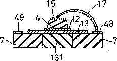
下面,参照图16和图17说明本发明的热电式红外线传感元件及其制造方法的第1实施例。图16是第1实施例的热电式红外线传感元件的结构的斜视图。如图16所示,热电式红外线传感元件111的结构是用粘接剂110将多层膜构造体112固定在其中央部附近具有略呈矩形剖面的开口部130的陶瓷基板107上。陶瓷基板107是例如大小为5mm×5mm、厚度1mm的矩形,中央部附近的开口部130的大小为1mm×1mm。另外,其材质例如为氧化铝等。多层膜构造体112具有(100)面取向的例如MgO等岩盐式晶体结构氧化物膜102(以下,简称为MgO膜102)、在MgO膜102之下形成的(100)面取向的Pt等引出电极膜103、在引出电极膜103之下的指定部分形成的例如作为电介质材料的钛酸镧铅等热电性电介质氧化物膜104(以下,简称为PLT膜104)和在PLT膜104之下形成的引出电极膜105,PLT膜部分104位于陶瓷基板107的开口部130。PLT膜104的大小例如为0.2mm×0.2mm,厚度3μm。另外,MgO膜102的大小例如为2mm×2mm,厚度2μm。在陶瓷基板107的表面的指定部分设有接续电极108和109,接续电极108和109分别通过导电性粘接剂106与引出电极103和105连接。Next, a first embodiment of the pyroelectric infrared sensor element and its manufacturing method according to the present invention will be described with reference to FIGS. 16 and 17. FIG. Fig. 16 is a perspective view showing the structure of the pyroelectric infrared sensor element of the first embodiment. As shown in FIG. 16, a pyroelectric
上述结构的热电式红外线传感元件111的制造方法示于图17。首先,在减压下,以800kgf/cm2对KBr粉体进行压制成形,并对其表面进行研磨使之平滑化,制成大小为3mm×3mm、厚度0.5mm的平板型KBr基板101,然后,在该基板101的表面上,利用等离子体MOCVD法,形成与该表面垂直的方向为结晶取向于<100>方向的岩盐式晶体结构氧化物的MgO膜102(大小为2mm×2mm,厚度2μm)(图17(a))。在该MgO膜102的形成中,使用乙酰丙酮配位基镁的蒸气作为CVD原料气体,将KBr基板101加热到400℃。然后,用溅射法在该MgO膜102的表面上的指定部分外延生长Pt膜,相对于膜面形成结晶取向于<100>方向的Pt膜的引出电极103(图17(b)),和先有的热电式红外线传感元件的制造一样,利用rf磁控管溅射法在引出电极103表面的指定部分和MgO膜102的未形成引出电极103的部分的一部分之上形成厚度3μm的结晶取向子C轴的PLT膜104(图17(b)),其次,在PLT膜104和MgO膜102的未形成引出电极103的部分的表面上利用溅射法形成Ni-Cr膜的引出电极膜105(图17(c))。A method of manufacturing the pyroelectric
然后,准备一块已经烧结了Pd膏预先在表面的指定部分形成了接续电极108和109的陶瓷基板107。并且,将经过上述各工序后得到的KBr基板101上的多层膜构造体112反转后,将该多层膜构造体112复盖住陶瓷基板107的开口部130,用导电性粘接剂106进行粘接,以使PLT膜104部分位于开口部130,并且使引出电极膜103和105分别与接触电极108和109接触。(图17(d))。通过将这样制作的构造物进行水洗处理,除去KBr基板101(图17(e))。进行干燥之后,再利用环氧树脂系列的粘接剂110将MgO膜102的周围部分与陶瓷基板107的表面粘接并固化后,便完成了热电式红外线传感元件111(图17(f))。Then, prepare a
在这样得到的热电式红外线传感元件111中,只用厚度仅为2μm的MgO膜102支撑具有热电效应的PLT膜104。但是,与PLT膜是利用聚酰亚胺树脂膜支撑的先有的热电式红外线传感元件相比,由于MgO膜102比聚酰亚胺树脂膜更薄、更硬,并且收缩率与PLT膜104没有太大差别,所以,机械强度足够大,并且不会发生由于裂缝等引起电极不导通的现象。In the pyroelectric
当使用分别以乙酰丙酮配位基镍和乙酰丙酮配位基钴作为原料气体采用等离子体MOCVD法制造的结晶取向于<100>方向的NiO膜或CoO膜代替结晶取向于<100>方向的岩盐式晶体构造氧化物的MgO膜102时,也可以制造具有同样性能的热电式红外线传感元件。When using nickel acetylacetonate ligand and cobalt acetylacetonate ligand as the raw material gas, NiO film or CoO film with crystal orientation in <100> direction produced by plasma MOCVD method replaces rock salt with crystal orientation in <100> direction When the
使用同样是碱卤化物材料的KCl、KI、CsBr、CsI等基板代替KBr基板101时,也可以制造具有同样性能的热电式红外线传感元件。When substrates such as KCl, KI, CsBr, and CsI, which are also alkali halide materials, are used instead of the
实施例9:Embodiment 9:
下面,参照图18和图19说明本发明的热电式红外线传感元件及其制造方法的第2实施例。图18是第2实施例的焦电式红外线传感元件的结构的斜视图。标以和上述图16及图17所示的第1实施例相同的符号的部件,实际上是相同的。如图18所示,热电式红外线传感元件211的结构是用粘接剂120将多层膜构造体113固定到其中央部附近具有略呈矩形剖面的开口部130的陶瓷基板107上。多层膜构造体113具有Ni金属电极膜114和在其下形成的(100)面取向的导电性NiO电极膜115、在导电性NiO电极膜115之下的指定部分形成的PLT膜104和在该PLT膜104之下形成的Ni-Cr电极膜116,PLT膜104部分位子开口部130。金属电极膜114的大小为2mm×2mm,厚度为0.8μm。导电性NiO膜112的大小为0.6mm×0.6mm,厚度0.4μm。PLT膜104的大小为0.2mm×0.2mm、厚度3μm。陶瓷基板107是和第1实施例一样的陶瓷制品,其大小为5mm×5mm,厚度1mm,中央部附近的开口部的大小为1mm×1mm,在陶瓷基板107上与粘接多层膜构造体113的面相同的一面的指定部分形成接续电极118,通过导电性膏121使接续电极118与金属电极膜114连接。另外,在陶瓷基板107反面,的指定位置上也形成接续电极119,利用Au线117将接续电极119与Ni-Cr电极膜116连接。Next, a second embodiment of the pyroelectric infrared sensor element and its manufacturing method of the present invention will be described with reference to FIGS. 18 and 19 . Fig. 18 is a perspective view showing the structure of the pyroelectric infrared sensor element of the second embodiment. Components assigned the same symbols as those of the first embodiment shown in FIGS. 16 and 17 are actually the same. As shown in FIG. 18 , a pyroelectric
上述结构的热电式红外线传感元件211的制造方法示于图19。首先,在和上述第1实施例相同制作的大小为3mm×3mm、厚度0.5mm的平板型KBr基板101的表面上,利用rf溅射法形成大小为2mm×2mm、厚度0.8μm的金属Ni膜114,然后,在金属Ni膜114的表面上,利用等离子体MOCVD法形成与基板表面垂直的方向为结晶取向于<100>方向的岩盐式晶体结构氧化物的导电性NiO膜115(添加锂)(大小为0.6mm×0.6mm、厚度0.4μm)(图19(a))。在该导电性NiO膜115的形成中,使用乙酰丙酮配位基镁的蒸气和二甲烷配位基锂(Liジピバロイルメタンキレ-ト)的蒸气的混合气体作为CVD原料气体将KBr基板101加热到400℃。并在该导电性NiO膜115的表面上利用和制造先有的热电式红外线传感元件一样的rf磁控管溅射法,通过外延生长PLT膜,形成厚度3μm的结晶取向于C轴的PLT膜104(0.2μm×0.2μm)(图19(b))。然后,利用溅射法在PLT膜104的表面上形成Ni-Cr电极膜116(图19(c))。A method of manufacturing the pyroelectric
然后,准备一块已经烧结了Pd膏预先在两表面的指定部分形成了接续电极118和119的陶瓷基板107。并且,将经过上述各工序后得到的KBr基板101上的多层膜构造体113反转后,将多层膜构造体113复盖到陶瓷基板107的开口部130上,用粘接剂120进行粘接,以使PLT膜104部分位于开口部130处(图19(d))。利用引线焊接法,用Au线117将Ni-Cr电极膜116与在陶瓷基板107的表面上形成的接续电极119连接(19(d))。然后,通过将这样制作的构造物进行水洗处理,除去KBr基板101并进行干燥后,利用导电性膏121将金属Ni膜114与在陶瓷基板107的表面上形成的接续电极118连接,便完成了热电式红外线传感元件211(图19(e))。Then, prepare a
在这样得到的热电式红外线传感元件211中,只用厚度仅为0.8μm的金属Ni膜114支撑具有热电效应的PLT膜104。但是,与PLT膜是利用聚酰亚胺树脂膜支撑的先有的热电式红外线传感元件相比,金属Ni膜114比聚酰亚胺树脂膜更薄、更硬、并且收缩率与PLT膜104没有什么差别,所以,强度足够大,而且不会发生由于裂缝而引起电极不导电的现象。In the pyroelectric
和上述实施例一样,使用同样是碱卤化物材料KCl、KI、CsBr、CsI等基板代替KBr基板101时,也可以制作具有同样性能的热电式红外线传感元件。Like the above-mentioned embodiment, when using the same alkali halide material KCl, KI, CsBr, CsI and other substrates instead of the
实施例10:Example 10:
下面,参照图20和图21说明本发明的热电式红外线传感元件及其制造方法的第3实施例。图20是第3实施例的热电式红外线传感元件的结构的斜视图。标以和上述图16及图17所示的第1实施例或图18及图19所示的第2实施例相同的符号的部件,实际上是相同的。如图20所示,第3实施例的热电式红外线传感元件311的结构是用粘接剂120将多层膜构造体122粘接到其中央部附近具有略呈矩形剖面的开口部130的陶瓷基板107上。该多层膜构造体122具有兼作电极的导电性NiO膜123和在其下形成的PLT膜104以及在该PLT膜104之下形成的Ni-Cr电极膜115,PLT膜104部分位于开口部130处,导电性NiO膜123的大小为2mm×2mm,厚度为2μm,PLT膜104的大小为0.2mm×0.2mm,厚度为3μm 。陶瓷基板107是和第1实施例一样的陶瓷制品,其大小为5mm×5mm,厚度1mm,中央部附近的开口部的大小为1mm×1mm。在与陶瓷基板107的粘接多层膜构造体122的面相同的面上的指定部分形成接续电极118,并通过导电性膏121将接续电极118与Ni金属电极膜114连接。另外,还在陶瓷基板107反面的指定位置形成接续电极119,利用Au线117将接续电极119与Ni-Cr电极膜116连接。Next, a third embodiment of the pyroelectric infrared sensor element and its manufacturing method of the present invention will be described with reference to FIGS. 20 and 21. FIG. Fig. 20 is a perspective view showing the structure of the pyroelectric infrared sensor element of the third embodiment. Components denoted by the same symbols as those of the first embodiment shown in FIGS. 16 and 17 or the second embodiment shown in FIGS. 18 and 19 are actually the same. As shown in FIG. 20 , the structure of the pyroelectric
上述结构的热电式红外线传感元件311的制造方法示于图21。首先,在和上述第1实施例一样制作的大小为3mm×3mm、厚度0.5mm的平板型KBr基板101的表面上,和第2实施例一样,使用等离子体MOCVD法形成与基板101的表面垂直的方向为结晶取向于<100>方向的岩盐式晶体结构氧化物的导电性NiO膜123(添加锂)(大小为2mm×2mm,厚度2μm)。(图21(a))。然后,利用和第1实施例一样的溅射法,在导电性NiO膜123的表面上通过外延生长PLT膜,形成厚度3μm的结晶取向于C轴的PLT膜104(0.2μm×0.2μm)(图21(b))。在PLT膜104的表面上形成Ni-Cr电极膜116(图21(c))。A method of manufacturing the pyroelectric
然后,准备一块已经烧结了Pd膏预先在两表面的指定部分形成了接续电极118和119的陶瓷基板107。并且,将经过上述各工序得到的KBr基板101上的多层膜构造体122反转后,将多层膜构造体122复盖到陶瓷基板107的开口部130上,并用粘接剂120进行粘接,以使PLT膜104部分位于开口部130处(图21(d))。然后,利用引线焊接法,用Au线117将Ni-Cr电极膜116与在陶瓷基板107的表面上形成的接续电极119连接(图21(d))。通过将这样得到的构造物进行水洗处理,除去KBr基板101并进行干燥后,利用导电性膏121将金属Ni膜114与在陶瓷基板107的表面上形成的接续电极118连接,便完成热电式红外线传感元件311(图21(e))。Then, prepare a
在这样得到的热电式红外线传感元件311中,只用厚度仅为2μm的NiO膜123支撑具有热电效应的PLT膜104。但是,与PLT膜是利用聚酰亚胺树脂膜支撑的先有的热电式红外线传感元件相比,NiO膜123比聚酰亚胺树脂膜更薄、更硬、并且收缩率与PLT膜104没有什么差别,所以,强度足够大,而且不会发生由于裂缝等引起电极不导通的现象。In the pyroelectric
和第1实施例一样,使用同样是碱卤化物材料KCl、KI、CsBr、CsI等基板代替KBr基板101时,也可以制作具有同样性能的热电式红外线传感元件。Similar to the first embodiment, when the base material KCl, KI, CsBr, CsI and the like are used instead of the
实施例11:Example 11:
下面,参照图22和图23说明本发明的热电式红外线传感元件及其制造方法的第4实施例,图22是第4实施例的热电式红外线传感元件的结构的斜视图。标以和上述图16及图17所示的第1实施例相同的符号的部件,实际上是相同的。如图22所示,第4实施例的热电式红外线传感元件411的结构是在其中央部附近具有略呈矩形剖面的开口部130的陶瓷基板107上直接形成多层膜构造体124。陶瓷基板107和第1实施例一样,例如是大小为5mm×5mm、厚度1mm的矩形,中央部附近的开口部130的大小为1mm×1mm。另外,其材质例如是氧化铝等。多层膜构造体124具有MgO膜102、在MgO膜102上形成的引出电极膜103、在引出电极103上的指定部分形成的PLT膜104和在PLT膜104上形成的引出电极膜105,PLT膜部分104位于陶瓷基板107的开口部130上。PLT膜104的大小例如为0.2mm×0.2mm、厚度3μm。另外,MgO膜102的大小例如为2mm×2mm,厚度2μm。在陶瓷基板107的表面的指定部分设有接续电极108和109,利用导电性膏136将引出电极105与接续电极128连接,利用导电性膏137将引出电极103与接续电极129连接。Next, a fourth embodiment of the pyroelectric infrared sensor element and its manufacturing method according to the present invention will be described with reference to FIGS. 22 and 23. FIG. 22 is a perspective view showing the structure of the pyroelectric infrared sensor element of the fourth embodiment. Components assigned the same symbols as those of the first embodiment shown in FIGS. 16 and 17 are actually the same. As shown in FIG. 22, the pyroelectric
上述结构的热电式红外线传感元件411的制造方法示于图23。预先准备一块在其中央部附近具有1mm×1mm的穿通的开口部130、大小为5mm×5mm、厚度1mm的氧化铝制的陶瓷基板107,通过在其表面的指定部分涂敷Pd膏并在1050℃下烧结,形成接续电极128和129。然后,将KBr粉体填充并固化到陶瓷基板107的开口部130部分后,在减压下加热到740℃,将KBr熔解,制成空间部分被填满的陶瓷基板171(图23(a))。再将KBr填充部172的表面研磨,使之平滑化。在具有这样制作的KBr填充部172的基板171的表面上,和第1实施例一样,利用等离子体MOCVD法,形成与基板表面垂直的方向为结晶取向于<100>方向的岩盐式晶体结构氧化物的MgO膜102(大小为2mm×2mm,厚度2μm)(图23(b))。再利用溅射法在MgO膜102的表面上指定部分,外延生产Pt膜,形成对膜面结晶取向于<100>方向的Pt膜的引出电极膜103(图23(b))。然后,利用rf磁控管溅射法在引出电极膜103和MgO膜102上未形成引出电极103的区域内指定部分的表面上形成厚度103μm的结晶取向于C轴的PLT膜104(图23(d))。再在PLT膜104和MgO膜102上未形成引出电极103的区域其余部分的表面上形成Ni-Cr膜的引出电极膜105(图23(e))。通过将这样制作的构造物进行水洗处理,除去KBr填充部分172(图23(e)),进行干燥后,利用导电性膏136和137分别将引出电极膜103与接续电极129以及引出电极膜105与接续电极128连接,便完成热电式红外线传感元件411(图23(f))。A method of manufacturing the pyroelectric
在这样得到的热电式红外线传感元件411中,只用厚度仅为2μm的MgO膜102支撑具有热电效应的PLT膜104。但是,与PLT膜利用聚酰亚胺树脂膜支持的先有的热电式红外线传感元件相比,MgO膜102比聚酰亚胺树脂膜更薄、更硬、并且收缩率与PLT膜104没有什么差别,所以,机械强度足够大,而且不会发生由于裂缝等引起电极不导电的现象。In the pyroelectric
同样当使用分别以乙酰丙酮配位基镍和乙酰丙酮配位基钴为原料气体用等离子体MOCVD法制造的结晶取向于<100>方向的NiO膜和CoO膜代替MgO膜102时,也可以制造具有同样性能的热电式红外线传感元件。另外,使用同样是碱卤化物材料KCl、KI、CsBr、CsI等粉体代替KBr粉体时,也可以制作具有同样性能的热电式红外线传感元件。Similarly, when the
实施例12:Example 12:
下面,参照图24和图25说明本发明的热电式红外线传感元件及其制造方法的第5实施例。图24是第5实施例的热电式红外线传感元件的结构的斜视图。标以和上述各实施例相同的符号的部件,实际上是相同的。如图24所示,第5实施例的热电式红外线传感元件511的结构是在中央部附近具有略呈矩形剖面的开口部130的陶瓷基板107上直接形成多层膜构造体125。陶瓷基板107和上述各实施例一样,例如是大小为5mm×5mm、厚度1mm的矩形,中央部附近的开口部130的大小为1mm×1mm。另外,其材质例如为氧化铝等。多层膜构造体125具有兼作电极的金属Ni膜114和在其上形成的导电性NiO膜115以及在导电性NiO膜115上的指定部分形成的PLT膜104和在PLT膜104上形成的Ni-Cr电极膜116,PLT膜部分104位于陶瓷基板107的开口部130上。金属Ni膜114的大小例如为2mm×2mm,厚度0.8μm,导电性NiO膜115的大小例如为0.6mm×0.6mm,厚度为0.4μm。另外,PLT膜104的大小例如为0.2mm×0.2mm,厚度为3μm。在陶瓷基板107的表面的指定部分设有接续电极128和129,利用导电性膏137将接续电极129与金属Ni膜114连接,利用Au线117将接续电极128与Ni-Cr电极膜116连接。Next, a fifth embodiment of the pyroelectric infrared sensor element and its manufacturing method of the present invention will be described with reference to FIGS. 24 and 25 . Fig. 24 is a perspective view showing the structure of the pyroelectric infrared sensor element of the fifth embodiment. Components denoted by the same symbols as in the above-mentioned embodiments are actually the same. As shown in FIG. 24, the pyroelectric
上述结构的热电式红外线传感元件511的制造方法示于图25。和第4实施例一样,预先准备一块其中央部附近具有1mm×1mm的穿通的开口部130、大小为5mm×5mm、厚度1mm的氧化铝制的陶瓷基板107,通过在其表面的指定部分涂敷Pd膏并在1050℃C下烧结,形成接续电极128和129。然后,将KBr粉体填充固化到陶瓷基板107的开口130部分后,在减压下加热到740℃,将KBr熔解,制作空间部分被填满的陶瓷基板171(图25(a))。再将KBr填充部172的表面研磨使之平滑化。在具有这样制作的KBr填充部分172的基板171的表面上,利用rf溅射法形成金属Ni膜114,再在金属Ni膜114的表面上,和实施例2一样利用等离子体MOCVD法形成与基板171的表面垂直的方向为结晶取向于<100>方向的岩盐式晶体结构氧化物的导电性NiO膜115(添加锂)(大小为0.6mm×0.6mm,厚度为0.4μm)。(图25(b))。再在导电性NiO膜115的表面上,利用和制造先有的热电式红外线传感元件一样的rf磁控管溅射法,通过外延生长PLT膜,形成厚度3μm的结晶取向于C轴的PLT膜104(0.2μm×0.2μm),在该PLT膜104的表面上利用溅射法形成Ni-Cr电极膜116(图25(c))。然后,利用引线焊接法,用Au线117将Ni-Cr电极膜116与接续电极128连接(图25(d))。通过将这样制作的构造物进行水洗处理,除去KBr填充部分172并进行干燥后,利用导电性膏137将金属Ni膜114与接续电极129连接,便完成热电式红外线传感元件511(图25(e))。A method of manufacturing the pyroelectric
在这样得到的热电式红外线传感元件511中,用厚度仅为0.8μm的金属Ni膜114支持具有热电效应的PLT膜104。但是,与PLT膜是利用聚酰亚胺树脂膜支撑的先有的热电式红外线传感元件相比。金属Ni膜114比聚酰亚胺树脂膜更薄、更硬、并且收缩率与PLT膜104没有什么差别,所以,机械强度足够大,而且不会发生由于裂缝等引起电极不导通的现象。In the pyroelectric
和第4实施例一样,使用同样是碱卤化物材料的KCl、KI、CsBr、CsI等代替KBr时,也可以制造具有同样性能的热电式红外线传感元件。As in the fourth embodiment, when KCl, KI, CsBr, CsI, etc., which are also alkali halide materials, are used instead of KBr, a pyroelectric infrared sensor element having the same performance can also be manufactured.
实施例13:Example 13:
下面,参照图26和图27说明本发明的热电式红外线传感元件及其制造方法的第6实施例。图26是第6实施例的热电式红外线传感元件的结构的斜视图。标以和上述各实施例相同的符号的部件,实际上是相同的。如图26所示,第6实施例的热电式红外线传感元件611的结构是在其中央部附近具有略呈矩形剖面的开口部130的陶瓷基板107上直接形成多层膜构造体126。陶瓷基板107和上述各实施例一样,例如是大小为5mm×5mm、厚度1mm的矩形,中央部附近的开口部130的大小为1mm×1mm。另外,其材质例如为氧化铝等。多层膜构造体126具有兼作电极的导电性NiO膜127、在导电性NiO膜127上的指定部分形成的PLT膜104和在PLT膜104上形成的Ni-Cr电极膜116,PLT膜部分104位于陶瓷基板107的开口部130上。导电性NiO膜127的大小例如为2mm×2mm、厚度2μm。另外,PLT膜104的大小例如为0.2mm×0.2mm,厚度3μm。在陶瓷基板107的表面的指定部分设有接续电极128和129,利用导电性膏137将接续电极129与导电性NiO膜127连接,利用Au线117将接续电极128与Ni-Cr电极膜116连接。Next, a sixth embodiment of the pyroelectric infrared sensor element and its manufacturing method of the present invention will be described with reference to FIGS. 26 and 27. Fig. 26 is a perspective view showing the structure of the pyroelectric infrared sensor element of the sixth embodiment. Components denoted by the same symbols as in the above-mentioned embodiments are actually the same. As shown in FIG. 26, the pyroelectric
上述结构的热电式红外线传感元件611的制造方法示于图27。和第4实施例一样,预先准备一块其中央部附近具有1mm×1mm的穿通的开口部130、大小为5mm×5mm、厚度1mm的氧化铝制陶瓷基板107,通过在其表面的指定部分涂敷Pd膏并在1050℃下烧结,形成接续电极128和129。然后,将KBr粉体填充固化到陶瓷基板107的开口部130部分之后,通过在减压下加热到740℃,将KBr溶解,制作空间部分被填满的陶瓷基板171(图27(a))。将KBr填充部分172的表面研磨使之平滑化。在具有这样制作的KBr填充部分172的基板171的表面上和第3实施例一样,利用等离子体MOCVD法形成与基板171的表面垂直的方向为结晶取向于<100>方向的岩盐式晶体结构氧化物的导电性NiO膜127(添加锂)(大小为2mm×2mm,厚度2μm)图27(b))。利用和第1实施例一样的溅射法,通过在导电性NiO膜127的表面上外延生长PLT膜,形成厚度3μm的结晶取向于c轴的PLT膜104(0.2μm×0.2μm),并在其表面上形成Ni-Cr电极膜116(图27(c))。然后,利用引线焊接法,用Au线117将Ni-Cr电极膜116与接续电极128连接(图27(d))。通过将这样制作的构造物进行水洗处理,除去KBr填充部分172并进行干燥后,利用导电性膏137将导电性NiO膜127与接续电极129连接,便完成热电式红外线传感元件611(图27(e))。A method of manufacturing the pyroelectric
在这样得到的热电式红外线传感元件611中,用厚度仅为2μm的导电性NiO膜127支撑具有热电效应的PLT膜104。但是,与PLT膜是利用聚酰亚胺树脂膜支撑的先有的热电式红外线传感元件相比,2μm厚的导电性NiO膜127比聚酰亚胺树脂膜更薄,更硬,并且收缩率与PLT膜104没有什么差别,所以,机械强度足够大,而且不会发生由于裂缝等引起电极不导通的现象。In the pyroelectric
另外,和第4实施例一样,使用同样是碱卤化物材料的KCl、KI、CsBr、CsI等代替KBr时,也可以制造具有同样性能的热电式红外线传感元件。In addition, as in the fourth embodiment, when KCl, KI, CsBr, CsI, etc., which are also alkali halide materials, are used instead of KBr, a pyroelectric infrared sensor element having the same performance can also be manufactured.
按照本发明的加速度传感元件,通过在其中央部分有穿通的空间部分的传感器保持基板上设置至少具有电极膜A、(100)面取向的电极膜B和在上述电极膜A与上述电极膜B之间存在的压电性电介质氧化物膜的多层膜构造体的结构,可以实现小型、轻量、精度高并且成本低的轻量自保持型加速度传感元件。According to the acceleration sensing element of the present invention, at least the electrode film A, the electrode film B oriented in the (100) plane is provided on the sensor holding substrate having a penetrating space portion at the central portion thereof, and the above electrode film A and the above electrode film The structure of the multilayer film structure of the piezoelectric dielectric oxide film present between B makes it possible to realize a small, lightweight, high-precision, and low-cost lightweight self-sustaining acceleration sensor element.
按照本发明的各制造方法,可以高效而合理地制造上述加速度传感元件。例如,在水溶性的基板上通过保持膜形成传感膜后,因为是利用水洗除去基板部分的制造工序,所以,可以很容易地制造小型并且价格低的轻量自保持型加速度传感元件。According to each manufacturing method of the present invention, the above-mentioned acceleration sensing element can be manufactured efficiently and rationally. For example, after forming a sensor film with a holding film on a water-soluble substrate, the substrate portion is removed by washing with water. Therefore, a small, low-cost, lightweight self-holding acceleration sensor element can be easily manufactured.
按照本发明的加速度传感器,是至少具有加速度传感元件、阻抗变换电路、滤波电路、放大电路、自诊断信号发生电路和温度补偿电路的加速度传感器,上述加速度传感元件通过在中央部分具有穿通的空间部分的传感器保持基板上固着由电极膜A、(100)面取向的电极膜B和在上述电极膜A与上述电极膜B之间存在的压电性电介质氧化物膜构成的多层膜构造体,可以实现小型、轻量、精度高并且成本低的轻量自保持型加速度传感器。According to the acceleration sensor of the present invention, it is an acceleration sensor having at least an acceleration sensing element, an impedance conversion circuit, a filter circuit, an amplification circuit, a self-diagnostic signal generating circuit, and a temperature compensation circuit. A multilayer film structure consisting of electrode film A, electrode film B oriented in the (100) plane, and a piezoelectric dielectric oxide film existing between the above electrode film A and the above electrode film B is fixed to the sensor holding substrate in the space portion body, a small, lightweight, high-precision, and low-cost lightweight self-holding type acceleration sensor can be realized.
如上所述,按照本发明的热电式红外线传感元件,为了保持热电性电介质氧化物膜,不使用先有的聚酰亚胺树脂膜,而使用比聚酰亚胺树脂膜更薄、更硬、并且收缩率与热电性电介质氧化物膜没有什么太大差别的氧化物膜或金属膜等,所以,不易发生电极断裂及保持膜龟裂的现象。另外,作为基板,由于不使用价格昂贵的在(100)面劈裂开进行镜面研磨的MgO单晶基板,所以,可以廉价地制造热电式红外线传感元件。按照本发明的热电式红外线传感元件的制造方法,由于使用可以利用水洗除去的碱卤化物作为基底基板,所以,不需要以往所需要的利用腐蚀方法特别小心地除去MgO单晶基板的工序,便可廉价地制造具有和先有的传感元件同样性能的热电式红外线传感元件。As described above, according to the pyroelectric infrared sensor element of the present invention, in order to maintain the pyroelectric dielectric oxide film, instead of using the conventional polyimide resin film, a film thinner and harder than the polyimide resin film is used. , and the shrinkage rate is not much different from the oxide film or metal film of the pyroelectric dielectric oxide film, so the phenomenon of electrode breakage and holding film cracking is less likely to occur. In addition, since an expensive MgO single crystal substrate cleaved in the (100) plane and mirror-polished is not used as the substrate, a pyroelectric infrared sensor element can be manufactured at low cost. According to the method of manufacturing the pyroelectric infrared sensor element of the present invention, since an alkali halide that can be removed by washing with water is used as the base substrate, the process of removing the MgO single crystal substrate with special care by etching, which was required in the past, is not required. A pyroelectric infrared sensor element having the same performance as a conventional sensor element can be manufactured cheaply.
Claims (45)
Applications Claiming Priority (4)
| Application Number | Priority Date | Filing Date | Title |
|---|---|---|---|
| JP1341394 | 1994-02-07 | ||
| JP013413/94 | 1994-02-07 | ||
| JP13698194 | 1994-06-20 | ||
| JP136981/94 | 1994-06-20 |
Publications (2)
| Publication Number | Publication Date |
|---|---|
| CN1121999A CN1121999A (en) | 1996-05-08 |
| CN1088918C true CN1088918C (en) | 2002-08-07 |
Family
ID=26349208
Family Applications (1)
| Application Number | Title | Priority Date | Filing Date |
|---|---|---|---|
| CN95101916A Expired - Fee Related CN1088918C (en) | 1994-02-07 | 1995-02-07 | Thin film sensor element and method of manufacturing the same |
Country Status (5)
| Country | Link |
|---|---|
| US (2) | US5612536A (en) |
| EP (1) | EP0667532B1 (en) |
| KR (1) | KR100262137B1 (en) |
| CN (1) | CN1088918C (en) |
| DE (1) | DE69532174T2 (en) |
Families Citing this family (21)
| Publication number | Priority date | Publication date | Assignee | Title |
|---|---|---|---|---|
| US6396200B2 (en) * | 1998-01-16 | 2002-05-28 | Mitsubishi Denki Kabushiki Kaisha | Thin film piezoelectric element |
| US6351057B1 (en) * | 1999-01-25 | 2002-02-26 | Samsung Electro-Mechanics Co., Ltd | Microactuator and method for fabricating the same |
| JP3438709B2 (en) * | 2000-08-31 | 2003-08-18 | セイコーエプソン株式会社 | Piezoelectric device, method of manufacturing the same, and method of manufacturing piezoelectric oscillator |
| KR100398363B1 (en) * | 2000-12-05 | 2003-09-19 | 삼성전기주식회사 | Film bulk acoustic resonator and method for fabrication thereof |
| JP3684233B2 (en) * | 2002-05-14 | 2005-08-17 | キヤノン株式会社 | Fingerprint input device and manufacturing method thereof |
| US7083270B2 (en) * | 2002-06-20 | 2006-08-01 | Matsushita Electric Industrial Co., Ltd. | Piezoelectric element, ink jet head, angular velocity sensor, method for manufacturing the same, and ink jet recording apparatus |
| JP3966237B2 (en) * | 2003-06-19 | 2007-08-29 | セイコーエプソン株式会社 | Piezoelectric devices and electronic devices equipped with piezoelectric devices |
| KR101238360B1 (en) * | 2006-08-16 | 2013-03-04 | 삼성전자주식회사 | Resonator and the method thereof |
| CA2588165C (en) * | 2007-05-07 | 2011-05-31 | Serge Mai | Quasi-autonomous energy storage and electric drive system |
| US8912036B2 (en) | 2007-08-24 | 2014-12-16 | The Regents Of The University Of Michigan | Growth of ordered crystalline organic films |
| KR100924533B1 (en) | 2007-09-19 | 2009-11-02 | 한국전기연구원 | Complex biosignal sensor |
| JP4930569B2 (en) * | 2009-10-14 | 2012-05-16 | 株式会社村田製作所 | Piezoelectric ceramic actuator for magnetic head drive |
| CN102107845B (en) * | 2009-12-25 | 2013-11-13 | 中国科学院金属研究所 | Micron sensing element, and preparation method and application thereof |
| US8866367B2 (en) | 2011-10-17 | 2014-10-21 | The United States Of America As Represented By The Secretary Of The Army | Thermally oxidized seed layers for the production of {001} textured electrodes and PZT devices and method of making |
| WO2014021701A1 (en) * | 2012-07-31 | 2014-02-06 | Universidad Nacional Autónoma de México | Device for sensing elastomechanical pulse disturbances |
| JP6264525B2 (en) * | 2013-03-25 | 2018-01-24 | セイコーエプソン株式会社 | Infrared sensor, heat detection element, and heat detection method using the same |
| DE102013209541A1 (en) * | 2013-05-23 | 2014-11-27 | Siemens Aktiengesellschaft | Sensor element arrangement and method for producing a sensor element arrangement |
| US10396755B2 (en) * | 2016-02-17 | 2019-08-27 | Samsung Electro-Mechanics Co., Ltd. | Resonator having frame and method of manufacturing the same |
| CN110178007B (en) * | 2017-01-11 | 2021-06-22 | 皇家飞利浦有限公司 | Integrated temperature sensor on lead selenide flat panel detector assembly |
| US10697090B2 (en) * | 2017-06-23 | 2020-06-30 | Panasonic Intellectual Property Management Co., Ltd. | Thin-film structural body and method for fabricating thereof |
| CN109371376B (en) * | 2018-12-04 | 2021-04-20 | 北京科技大学 | A kind of controllable preparation method of single crystal orientation NiO thin film |
Family Cites Families (17)
| Publication number | Priority date | Publication date | Assignee | Title |
|---|---|---|---|---|
| DE144482C (en) * | ||||
| US4066527A (en) * | 1975-07-18 | 1978-01-03 | Futaba Denshi Kogyo K. K. | Method of producing semiconductor device |
| US4339764A (en) * | 1977-05-27 | 1982-07-13 | The United States Of America As Represented By The Secretary Of The Navy | PbSx Se1-x semiconductor |
| US4480209A (en) * | 1981-10-09 | 1984-10-30 | Clarion Co., Ltd. | Surface acoustic wave device having a specified crystalline orientation |
| US4532424A (en) * | 1983-04-25 | 1985-07-30 | Rockwell International Corporation | Pyroelectric thermal detector array |
| JPS60189307A (en) * | 1984-03-09 | 1985-09-26 | Toshiba Corp | Piezoelectric thin film resonator and its manufacture |
| JPH0685450B2 (en) * | 1986-01-13 | 1994-10-26 | 松下電器産業株式会社 | Ferroelectric thin film element |
| JPH0672800B2 (en) * | 1986-03-12 | 1994-09-14 | 松下電器産業株式会社 | Pyroelectric infrared sensor |
| FR2656689A1 (en) * | 1989-12-29 | 1991-07-05 | Philips Electronique Lab | PYROELECTRIC SENSOR ELEMENT AND DEVICES FOR DETECTION OF THERMAL PHENOMENA. |
| US5210455A (en) * | 1990-07-26 | 1993-05-11 | Ngk Insulators, Ltd. | Piezoelectric/electrostrictive actuator having ceramic substrate having recess defining thin-walled portion |
| JP2584124B2 (en) * | 1990-11-01 | 1997-02-19 | 松下電器産業株式会社 | Pyroelectric infrared detector and method of manufacturing the same |
| US5209119A (en) * | 1990-12-12 | 1993-05-11 | Regents Of The University Of Minnesota | Microdevice for sensing a force |
| US5286975A (en) * | 1991-05-29 | 1994-02-15 | Matsushita Electric Industrial Co., Ltd. | Pyro-electric type infrared-ray sensor |
| JPH05283756A (en) * | 1992-03-31 | 1993-10-29 | Murata Mfg Co Ltd | Ferroelectric thin film element |
| US5413667A (en) * | 1992-11-04 | 1995-05-09 | Matsushita Electric Industrial Co., Ltd. | Pyroelectric infrared detector fabricating method |
| US5387459A (en) * | 1992-12-17 | 1995-02-07 | Eastman Kodak Company | Multilayer structure having an epitaxial metal electrode |
| KR950001303A (en) * | 1993-06-22 | 1995-01-03 | 이헌조 | Thin film infrared sensor structure and manufacturing method |
-
1995
- 1995-01-19 US US08/374,989 patent/US5612536A/en not_active Expired - Fee Related
- 1995-01-23 EP EP95100861A patent/EP0667532B1/en not_active Expired - Lifetime
- 1995-01-23 DE DE69532174T patent/DE69532174T2/en not_active Expired - Fee Related
- 1995-02-06 KR KR1019950002031A patent/KR100262137B1/en not_active Expired - Fee Related
- 1995-02-07 CN CN95101916A patent/CN1088918C/en not_active Expired - Fee Related
-
1996
- 1996-02-09 US US08/600,863 patent/US6105225A/en not_active Expired - Fee Related
Also Published As
| Publication number | Publication date |
|---|---|
| EP0667532A3 (en) | 1998-07-22 |
| EP0667532A2 (en) | 1995-08-16 |
| DE69532174T2 (en) | 2004-04-15 |
| CN1121999A (en) | 1996-05-08 |
| EP0667532B1 (en) | 2003-11-26 |
| US6105225A (en) | 2000-08-22 |
| KR950026041A (en) | 1995-09-18 |
| KR100262137B1 (en) | 2000-07-15 |
| US5612536A (en) | 1997-03-18 |
| DE69532174D1 (en) | 2004-01-08 |
Similar Documents
| Publication | Publication Date | Title |
|---|---|---|
| CN1088918C (en) | Thin film sensor element and method of manufacturing the same | |
| JP4648030B2 (en) | Yttria sintered body, ceramic member, and method for producing yttria sintered body | |
| CN1082256C (en) | Ceramic film structure body and making method thereof | |
| CN1243573A (en) | Mass sensor and mass detection method | |
| JP4796354B2 (en) | Electrostatic chuck and method for producing yttria sintered body | |
| CN1596362A (en) | Thin-film micromachine resonator, thin-film micromachine resonator gyroscope, navigation system using the thin-film micromachine resonator gyroscope, and automobile | |
| JP5154871B2 (en) | Electrostatic chuck and manufacturing method thereof | |
| US20060242807A1 (en) | Piezoelectric/electrostrictive device and method for manufacturing the same | |
| KR20080025012A (en) | Electrostatic chuck and its manufacturing method | |
| JP2006128603A (en) | Ceramic member and manufacturing method therefor | |
| CN101981718A (en) | Piezoelectric film and manufacturing method thereof, angular velocity sensor, angular velocity measuring method using angular velocity sensor, piezoelectric power generating element, and power generation method using piezoelectric power generating element | |
| CN1162962C (en) | External coating substrates for electronic components and piezoelectric resonant components | |
| JP2010177448A (en) | Piezoelectric/electrostrictive element and manufacturing method of the same | |
| US20060113876A1 (en) | Piezoelectric/electrostrictive device | |
| CN1670978A (en) | Electronic device manufacturing method | |
| US7713366B2 (en) | Piezoelectric/electrostrictive film and method for producing the same | |
| CN1175563C (en) | Piezo-electric resonator and its parts | |
| CN1050008C (en) | Piezoelectric/electrostrictive film element and method of producing the same | |
| CN1502469A (en) | Piezoelectric ceramics, actuator and manufacturing method thereof, printing head and inkjet printer | |
| CN1892231A (en) | Acceleration sensor and magnetic disk device using same | |
| JPWO2006046494A1 (en) | Piezoelectric / electrostrictive device | |
| CN1615670A (en) | Piezoelectric body manufacturing method, piezoelectric body, ultrasonic probe, ultrasonic diagnosing device, and nondestructive inspection device | |
| JP3377874B2 (en) | Thin film sensor element and method of manufacturing the same | |
| CN1052538C (en) | Semiconductor type differential pressure measurement apparatus and method for manufacturing the same | |
| Juuti et al. | Manufacturing of prestressed piezoelectric unimorphs using a postfired biasing layer |
Legal Events
| Date | Code | Title | Description |
|---|---|---|---|
| C06 | Publication | ||
| PB01 | Publication | ||
| C10 | Entry into substantive examination | ||
| SE01 | Entry into force of request for substantive examination | ||
| C14 | Grant of patent or utility model | ||
| GR01 | Patent grant | ||
| C19 | Lapse of patent right due to non-payment of the annual fee | ||
| CF01 | Termination of patent right due to non-payment of annual fee |