CN1088874C - A peripheral card having independent functionality and method used therewith - Google Patents
A peripheral card having independent functionality and method used therewith Download PDFInfo
- Publication number
- CN1088874C CN1088874C CN95191101.5A CN95191101A CN1088874C CN 1088874 C CN1088874 C CN 1088874C CN 95191101 A CN95191101 A CN 95191101A CN 1088874 C CN1088874 C CN 1088874C
- Authority
- CN
- China
- Prior art keywords
- pcmcia
- registers
- signal
- reset
- peripheral device
- Prior art date
- Legal status (The legal status is an assumption and is not a legal conclusion. Google has not performed a legal analysis and makes no representation as to the accuracy of the status listed.)
- Expired - Lifetime
Links
- 230000002093 peripheral effect Effects 0.000 title claims abstract description 75
- 238000000034 method Methods 0.000 title description 2
- 230000001419 dependent effect Effects 0.000 claims abstract description 5
- 238000004891 communication Methods 0.000 claims description 18
- 230000004044 response Effects 0.000 claims description 7
- 230000000977 initiatory effect Effects 0.000 claims description 2
- 230000001747 exhibiting effect Effects 0.000 abstract 1
- 230000006870 function Effects 0.000 description 10
- 238000010586 diagram Methods 0.000 description 4
- 238000012360 testing method Methods 0.000 description 3
- 230000003139 buffering effect Effects 0.000 description 2
- 239000002253 acid Substances 0.000 description 1
- 238000013461 design Methods 0.000 description 1
- 230000002452 interceptive effect Effects 0.000 description 1
- 230000007246 mechanism Effects 0.000 description 1
- 238000012986 modification Methods 0.000 description 1
- 230000004048 modification Effects 0.000 description 1
- 238000012545 processing Methods 0.000 description 1
- 230000007704 transition Effects 0.000 description 1
Images

Classifications
-
- G—PHYSICS
- G06—COMPUTING; CALCULATING OR COUNTING
- G06F—ELECTRIC DIGITAL DATA PROCESSING
- G06F13/00—Interconnection of, or transfer of information or other signals between, memories, input/output devices or central processing units
- G06F13/38—Information transfer, e.g. on bus
- G06F13/40—Bus structure
- G06F13/4063—Device-to-bus coupling
- G06F13/4068—Electrical coupling
Landscapes
- Engineering & Computer Science (AREA)
- General Engineering & Computer Science (AREA)
- Theoretical Computer Science (AREA)
- Computer Hardware Design (AREA)
- Physics & Mathematics (AREA)
- General Physics & Mathematics (AREA)
- Power Sources (AREA)
Abstract
A PCMCIA card having independent functionality and alternatively arranged to operate in conjunction with a host computer, that includes a peripheral apparatus (109) having an integral CPU (125), a power source (129), and a power supply (127) for exhibiting an independent operating state; and an interface function (121) integral with and coupled to said peripheral apparatus (109), said interface function arranged and constructed to couple said peripheral apparatus to the host computer (101) over a PCMCIA compliant interface and initiate a dependent operating state at said peripheral apparatus (109).
Description
The present disclosure relates to peripheral features that are configured and connected to a host interface, and more particularly, but not exclusively, to a stand-alone feature in the form of a peripheral card having an interface as permitted by the PC memory card International association (pcmcia) so as to be operable in association with a host.
General or special purpose host computers often include devices with various peripheral functions, such as a communications modem, expansion memory, or an added hard drive. To facilitate the addition of various peripheral devices, the PC memory card international association (PCMCIA) has been working on the standardization of a range of peripheral device cards with the requisite PCM CIA interface. Parameters specified by PCMCIA can be found in the PC card standard 2.0 report. The report is published by PCMCIA (1030B East DuaneAvenue, Sunnyvale California), and the standard is incorporated herein by reference. The specified parameters include physical parameters (such as size), input/output connections (such as control, address and data buses), signal parameters (such as operating level, impedance, power supply level, power supply polarity and level) and specific operating steps.
Based on the host-supported provisions for add-on devices, such as PCMCIA devices, it is generally known that PCMCIA peripheral cards receive power from a host socket and are controlled by a single RESET (RESET) line when inserted or removed from the host socket to restore functionality.
However, a new type of PCMCIA device, such as the wireless modem products offered by Motorola, Inc. at 1303 EastAlgorquin Road, Schaunburg, Illinois 60139, is designed to continue to operate when the jack is removed or when both the jack and the host have been powered down. These PCMCIA devices have their own power supply and CPU, which allows each device to remain independently functional once removed from the host socket. This transition in operating mode allows the user to enhance the ability to: the device may remain in the network when removed from the host, thus operating in a manner that allows it to maintain a portion of the communication link, such as storing information until a peripheral plug-in is reinserted into the host.
However, because the design functions of the existing PCMCIA peripheral card conform to the PCMCIA standard, that is, only the power and reset states are generated by the host. Thereby generating an undesirable phenomenon. This phenomenon causes unnecessary or unintentional resets of the circuitry on the peripheral card, thereby interfering with the intended or intended function of the device.
It is clear that there is a need for a peripheral function or card having a PCMCIA enabled interface that has the added capability to reliably operate in a deterministic manner in an environment where both the host device and the peripheral device have their own CPU and power supply.
To this end, the present invention provides a PCMCIA card having stand-alone functionality and also being arranged to operate in connection with a host processor, the card comprising:
a peripheral device comprising an external processor, power supply means, and a voltage detector operative to assert a PCMCIA Voltage Detect (PVD) signal, said peripheral device being adapted to operate in a compliant operating state and an independent operating state, said external processor initiating said compliant operating state at said peripheral device in response to said PVD signal;
an interface feature coupled to said peripheral device, said interface feature including a plurality of status compliance registers that are selectively reset based on changes in the operating status of the peripheral device, said interface feature being arranged and configured to couple said peripheral device to a host processor via a PCMCIA compliant interface, wherein said plurality of status compliance registers include: a first set of registers associated with said PCMCIA card, said PCMCIA card being coupled to said host processor through said PCMCIA compliant interface, said host processor being operative to assert a PCMCIA Reset (PRESET) signal to reset said first set of registers and a second set of registers coupled to said external processor, said external processor being operative to assert a CPU Reset (CRESET) signal to reset said second set of registers.
The invention also provides an external plug-in arranged to operate in connection with a host processor and also having independent functionality, the plug-in comprising in combination:
a peripheral device comprising an external processor, a power supply, and a voltage detector operative to de-assert a PCMCIA Voltage Detect (PVD) signal, the peripheral device adapted to comply with an operational state when operatively connected to the main processor and to operate independently when not coupled to the main processor, and
an interface coupled to said peripheral device, said interface including a plurality of status-dependent registers that are selectively reset in response to changes in the operating status of the peripheral device, wherein the plurality of status-dependent registers includes a first set of registers associated with the mode of the interface and a second set of registers that are changeable by the host processor, the read interface being arranged and configured to couple said peripheral device to said host processor; and
wherein the external processor initiates the independent operational state on the peripheral device in response to the PVD signal, and de-assertion of the PVD signal also resets the first and second sets of registers.
The features of the present invention, which are believed to be novel, are set forth with particularity in the appended claims. The invention, however, together with further advantages thereof, may best be understood by reference to the accompanying drawings. Wherein,
FIG. 1 is a block diagram of a host and peripheral card adapted for use in accordance with a preferred embodiment of the present invention.
FIG. 2 is a detailed block diagram of the peripheral plug-in shown in FIG. 1.
Fig. 3 is a flow chart of steps to be performed in the peripheral add-in to determine whether it is a stand-alone or compliant operating condition.
Generally, the disclosure herein relates to a peripheral device for a host. The peripheral device includes a peripheral card having a PCMCIA enabled interface. Such peripheral cards are often utilized and offer advantages when the peripheral device contains independent functionality, such as would be apparent when the peripheral device contains a separate power supply and Controller (CPU). The preferred embodiment is a peripheral card that exhibits independent and compliant operating conditions and also has an interface function coupled to the peripheral card. The interface function couples the peripheral card to the host through a PCMCIA enabled interface and initiates a compliant operating state of the peripheral card when the peripheral card is plugged into the host or when power is subsequently supplied to the host. The interface function coupled to the peripheral card in the compliant operating state enables the independent operating state of the card after the peripheral card is removed from the host or the host is powered down.
Preferred embodiments according to the present invention will be further described with reference to the accompanying drawings. Fig. 1 is a block diagram of a host (101) and peripheral device (120) adapted to use the preferred embodiment of the present invention. The host (101) depicted in fig. 1 has a PCMCIA slot interface integrated circuit (103) or similar circuit and a PCMCIA connector (105). The peripheral device (120) includes a peripheral card (109) having a PCMCIA interface logic (121), a voltage detector (123), a CPU (125), a power supply (127), a transceiver (128), a battery (129), and a PCMCIA connector (132).
The peripheral device (120) is coupled, interfaced or connected to the host computer (101) by plugging the PCMCIA connector (132) of the peripheral card (109) into the PCMCIA connector (105) on the host computer (101). All of these components (121), (123), (125), (127), (128), (129), and (132) of the peripheral device may actually be located on a PCMCIA compliant or conforming card, or the PCMCIA connector (132) may actually be separate from the peripheral card (109) and connected by some mechanism, such as by cable. The host computer (101) may be any general purpose computer that includes a PCMCIA interface, both functional and logical, and preferably substantially conforming to the PCMCIA standard. The preferred embodiment of the present invention is considered to be compatible with the PCMCIA standard and the PCMCIA interfaces, ports defined by the standard, as long as its operation is at least partially compatible with the PCMCIA interface and transparent to the hardware, operating system software, or other attributes of the host computer.
In any case, a preferred embodiment of a peripheral plug-in (109) thereof comprises: a controller, preferably a central processing unit CPU (125) with RAM and ROM (e.g., a Motorola MCM68300 series microprocessor); a radio transceiver (128) that transceives data over a communication medium well known in the art; a power supply (127) and a power source connected to the power supply (127), the power source preferably being a NiCAD battery (129) or a 9 volt alkaline or lead acid battery (129); they are interconnected as depicted in the figures. It is apparent that circuitry in the power supply (127) allows the CPU (125) to detect the status of the power supply (127) to determine the operating status of the peripheral package (109).
In the preferred embodiment, the PCMCIA will initiate a stand-alone mode of operation as described below whenever the PCMCIA connector (105) is separated from the PCMCIA connector (132) to thereby separate, decouple or remove the peripheral card (109) from the host computer (101), or when the power to the host PCMCIA slot interface (103) is turned off while the peripheral device (120) is still plugged into the host computer.
When the PCMCIA power line PCMCIA5V (131) voltage is below the preset voltage level, the voltage detector (123) will not assert the PVD signal (133), which in turn will generate a CPU interrupt signal, GPINT (221). Upon receipt of this interrupt signal, the CPU determines the current state of the PVD signal, which can be read as a one-bit signal through the PCMCIA interface logic (121). The CPU determines that the PVD is unasserted and initiates a stand-alone operation. At the same time, the deassertion of the PVD signal (133) causes the first register set (201) to be cleared to a default state and the default state is maintained until the card is reinserted into the power-on PCMCIA slot. In this way, when the card is reinserted into the PCMCIA slot, it is ensured that the PCMCIA interface will operate in a memory-only mode (as opposed to an I/O mode) regardless of the interface mode established when the card is removed from the slot.
As a result, when the card is reinserted or the PCMCIA slot of the host is powered, the PCMCIA card will initiate a compliant operating state upon assertion of the PVD signal. When the voltage on the PCMCIA power line PCMCIA5V (131) exceeds the preset voltage, the voltage detector (123) asserts the PVD signal (133), which in turn generates a CPU interrupt signal GPINT (221). Upon receipt of this interrupt signal, the CPU determines the current state of the PVD signal, which can be read as a bit through the PCMCIA interface logic (121). After the CPU has determined that PVD is recognized, a compliant operating condition is initiated.
To avoid unnecessary resetting of the circuit, PCMCIA cards use four reset signals, each of which resets a particular range of the circuit. The P-RESET (135) signal and the PVD signal (when unasserted) generated by the PCMCIA host (101) essentially RESET those circuits that are directly controlled by the PCMCIA host. The C-RESET circuit mainly RESETs those circuits controlled by an integral CPU (125). The fourth reset signal, the power on reset signal POR (137), is generated by the on-board power supply to reset all the circuitry on the PCMCIA card. POR is asserted (active low) when the on-board power supply output voltage level is below the lowest operating voltage of the lowest power PCMCIA card of the PCMCIA card.
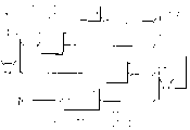
FIG. 2 is a detailed block diagram of the peripheral plug-in shown in FIG. 1. The interface function or PCMCIA interface logic (121) includes three main functional blocks: a first set of registers or PCMCIA registers (201), a second set of registers or CPU registers (203), and a communication block (205) having a third set of registers (206).
The first set of registers (201) contains a plurality of registers that can be read and written via PCMCIA interface via PCMCIA read and write signals 299 and 297, but which can only be read via CPU interface via CPU read signal 295. The first set of registers may be reset by any one of three reset conditions coupled through OR gates (211), respectively: the PREST signal (135) is asserted, the POR active low signal (137) is asserted or the PVD signal (133) is not asserted. The second set of registers (203) includes a plurality of registers that can be read and written to via the CPU interface via CPU read and write signals 295 and 293. But these registers can only be read via the PCMCIA interface via the PCMCIA read signal 299. The second set of registers may be reset by the CRESET LOW ACTIVE signal (139) or the POR LOW ACTIVE asserted signal. The communication block (205) comprises a third set of registers (206) and their associated logic, such as FIFO memory registers and control logic registers. The FIFO memory register is used for buffering data from the PCMCIA interface to the CPU interface and buffering data from the CPU interface to the PCMCIA interface. The communication block (205) may be reset by any one of four reset conditions coupled through OR gates 215, respectively, which are: the PRESET signal (135) is asserted, the POR active low signal (137) is asserted, the CRESET active low signal (139) is asserted, or the PVD signal (133) is not asserted.
As previously described, the PCMCIA card uses the four reset signals described, each resetting a particular range of circuits, in order to avoid unnecessary circuit reset phenomena.
The host asserts the P-RESET signal (135) when it wishes to place the card in a default state (typically when a new card is inserted into the slot) or when the host itself RESETs. Assertion of the P-RESET signal (135) RESETs the first set of registers or PCMCIA registers (201) and the third set of registers (205) associated with the interface function or PCMCIA interface logic (121). This results in those registers associated with the card interface mode being reset for memory access only, those registers previously modified by the PCMCIA host being reset, and the communication block being cleared in advance for the new communication session.
The PCMCIA interface logic (121) further includes a second set of registers or CPU registers (203) coupled to the unified CPU (125). The integral CPU (125) asserts CRESET when it wishes to place the plug-in a default state (typically a software reset, as a result of expiration of a watchdog timer) or to recover from an error condition*Signal (of here "*"indicates that the low state is effective). CRESET*Assertion resets the second and third sets of registers (205) coupled to the CPU (125). This resets all registers that have been modified by the CPU and clears the communication blocks in advance for a new communication session.
Signal POR*(137) Assertion resets all of the first set of registers, the second set of registers, and the communication block to fully reset the PCMCIA interface logic (121) after the power supply output has stabilized above a minimum operating level. Referring to FIG. 1, POR*The signal (137) is coupled to CRESET through a diode (141)*Signal (139) to let POR*The signal can also reset the CPU (125) and the transceiver (128).
The deassertion of the PVD signal (133) is used to reset the first set of registers (201) and the third set of registers (205). This allows those registers associated with the card interface mode to be reset to memory access only when the PCMCIA card is reinserted into the powered PCMCIA slot, and also resets other memory that has been modified by the PCMCIA host and pre-clears the communication block for a new communication session.
Fig. 3 is a flow chart of steps to be performed in a peripheral plug-in order to determine whether the peripheral plug-in is in a compliant state or a stand-alone state. Beginning with a START block 302, proceeding next is a block 304 where the power supply to the card is turned on by a power switch on the card. This causes the on-board power supply to generate a power-on reset, resetting all circuits on the card. During initialization of the card, the integral CPU checks whether the PCMCIA interface is powered by detecting the PCMCIA voltage test (PVD) signal at block 306. If PVD is identified, i.e., PVD is 1, then at block 308, the CPU places the plug-in compliance; otherwise, the CPU places the plug-in a stand-alone state at block 314.
The interface circuit monitors the PCMCIA power line when the card is in a compliant operating state. If the card is removed from the slot or the slot is unpowered, PVD is set to 0 at block 316 and a PVD differential interrupt is generated for the unified CPU at block 318.
Similarly, the interface circuit monitors the PCMCIA power line when the card is in the stand-alone operating state. If a card is placed in the slot and power is present in the slot at block 310, then PVD is set to 1 at block 312 and a differential PVD interrupt is generated for the unified CPU at block 320.
When the CPU receives a PVD differential interrupt, the integrated CPU checks whether the PCMCIA interface is powered by detecting a PCMCIA voltage test (PVD) signal. If the PVD is identified, i.e., PV 1, the CPU places the card in a compliant operating state, otherwise the CPU places the card in a stand-alone operating state.
Those skilled in the art will recognize that the present invention provides a peripheral card with independent functionality that operates in an independent state when decoupled from a host and in a compliant operating state when coupled to the host. Further, the peripheral card can operate in connection with the host through a PCMCIA enabled interface as an alternative or additional capability to the peripheral card.
It will also be apparent to those skilled in the art that the invention as disclosed may be modified in numerous ways and may be considered in numerous embodiments other than the preferred embodiments set out and described above.
Another embodiment of the present invention would not require a voltage testing scheme like that used in the preferred embodiment described above, but would use a watchdog timer instead. If the host has not interacted with the PCMCIA card after a preset period of time, the PCMCIA card assumes that it has been disengaged from the slot. The CPU on the PCMCIA card will place the card in a stand-alone operating state. Thereafter, if communication with the main processor is restored, the CPU on the PCMCIA card will resume its compliant operating state.
Therefore, it is intended that the appended claims cover all modifications of the invention which fall within the true spirit and scope of the invention.
Claims (10)
1. A PCMCIA card having stand-alone functionality and also being arranged to operate in connection with a host processor, the card comprising:
a peripheral device comprising an external processor, power supply means, and a voltage detector operative to assert a PCMCIA Voltage Detect (PVD) signal, said peripheral device being adapted to operate in a compliant operating state and an independent operating state, said external processor initiating said compliant operating state at said peripheral device in response to said PVD signal;
an interface feature coupled to said peripheral device, said interface feature including a plurality of status compliance registers that are selectively reset based on changes in the operating status of the peripheral device, said interface feature being arranged and configured to couple said peripheral device to a host processor via a PCMCIA compliant interface, wherein said plurality of status compliance registers include: a first set of registers associated with said PCMCIA card, said PCMCIA card being coupled to said host processor through said PCMCIA compliant interface, said host processor being operative to assert a PCMCIA Reset (PRESET) signal to reset said first set of registers and a second set of registers coupled to said external processor, said external processor being operative to assert a CPU Reset (CRESET) signal to reset said second set of registers.
2. The PCMCIA card of claim 1, wherein said plurality of status compliance registers further comprises a communication block having a third set of registers coupled to said main processor, said main processor operative to assert a PCMCIA Reset (PRESET) signal to reset the communication block.
3. The PCMCIA card of claim 2, wherein said interface function further comprises said communication block coupled to said external processor, said external processor operative to assert a CPU Reset (CRESET) signal to reset the communication block.
4. The PCMCIA card of claim 1, wherein the peripheral device further comprises a transceiver.
5. The PCMCIA card of claim 1, further comprising a first status bit set by an assertion of said PVD signal, and readable by the CPU.
6. The PCMCIA card of claim 5, wherein an interrupt to said CPU is generated whenever said first status bit is changed.
7. The PCMCIA card of claim 1, further comprising a second status bit set by an assertion of said PRESET signal and readable by said CPU.
8. The PCMCIA card of claim 7, wherein an interrupt to said CPU is generated whenever said second status bit is set.
9. A PCMCIA card according to claim 1, wherein said power supply asserts a power-on reset (POR) signal in response to a preset voltage level, said power-on reset signal resetting all circuitry on said PCMCIA card.
10. An external plug-in configured to operate in connection with a host processor and also having independent functionality, the plug-in comprising, in combination:
a peripheral device comprising an external processor, a power supply, and a voltage detector operative to de-assert a PCMCLA Voltage Detect (PVD) signal, the peripheral device adapted to comply with an operational state when operatively connected to the main processor and to operate independently when not coupled to the main processor, and
an interface coupled to said peripheral device, said interface including a plurality of status-dependent registers that are selectively reset in response to a change in an operating state of the peripheral device, wherein the plurality of status-dependent registers includes a first set of registers associated with a mode of the interface and a second set of registers that are changeable by the host processor, the interface being arranged and configured to couple said peripheral device to said host processor; and
wherein the external processor initiates the independent operational state on the peripheral device in response to the PVD signal, and de-assertion of the PVD signal also resets the first and second sets of registers.
Applications Claiming Priority (2)
| Application Number | Priority Date | Filing Date | Title |
|---|---|---|---|
| US08/332,008 | 1994-10-31 | ||
| US08/332,008 US5613095A (en) | 1994-10-31 | 1994-10-31 | Peripheral card having independent functionally and method used therewith |
Publications (2)
| Publication Number | Publication Date |
|---|---|
| CN1137831A CN1137831A (en) | 1996-12-11 |
| CN1088874C true CN1088874C (en) | 2002-08-07 |
Family
ID=23296310
Family Applications (1)
| Application Number | Title | Priority Date | Filing Date |
|---|---|---|---|
| CN95191101.5A Expired - Lifetime CN1088874C (en) | 1994-10-31 | 1995-09-13 | A peripheral card having independent functionality and method used therewith |
Country Status (4)
| Country | Link |
|---|---|
| US (1) | US5613095A (en) |
| CN (1) | CN1088874C (en) |
| AU (1) | AU3631195A (en) |
| WO (1) | WO1996013802A1 (en) |
Families Citing this family (23)
| Publication number | Priority date | Publication date | Assignee | Title |
|---|---|---|---|---|
| US5805416A (en) * | 1995-09-11 | 1998-09-08 | Norand Corporation | Modular hand-held data capture terminal |
| JPH0991397A (en) * | 1995-09-25 | 1997-04-04 | Nec Corp | Separation type pc card |
| US5974161A (en) * | 1996-03-01 | 1999-10-26 | Hewlett-Packard Company | Detachable card for capturing graphics |
| US5919259A (en) * | 1997-04-18 | 1999-07-06 | Dahl; Nathaniel H. | Method and apparatus for supplying power to a CPU using an adaptor card |
| US6047342A (en) * | 1998-03-31 | 2000-04-04 | Apple Computer, Inc. | PC processing card for decoding operations |
| US6128682A (en) * | 1998-06-25 | 2000-10-03 | Compaq Computer Corporation | Method and apparatus for bus isolation |
| JP3819658B2 (en) * | 1999-12-27 | 2006-09-13 | 三洋電機株式会社 | Portable electronic devices with a common serial bus connector |
| US7005966B1 (en) * | 2000-05-18 | 2006-02-28 | Micron Technology, Inc. | Remote computer controller and control method |
| AU2001282935A1 (en) | 2000-08-01 | 2002-02-13 | First Usa Bank, N.A. | System and method for transponder-enabled account transactions |
| US6631849B2 (en) * | 2000-12-06 | 2003-10-14 | Bank One, Delaware, National Association | Selectable multi-purpose card |
| US7526449B1 (en) | 2001-04-17 | 2009-04-28 | Jpmorgan Chase Bank N.A. | Optically encoded card and system and method for using |
| US20030019942A1 (en) * | 2001-07-24 | 2003-01-30 | Blossom George W. | System and method for electronically readable card having power source |
| US8392301B1 (en) | 2002-03-08 | 2013-03-05 | Jpmorgan Chase Bank, N.A. | Financial system for isolated economic environment |
| AU2003225744A1 (en) | 2002-03-08 | 2003-09-22 | Jp Morgan Chase Bank | Financial system for isolated economic environment |
| US20040210498A1 (en) * | 2002-03-29 | 2004-10-21 | Bank One, National Association | Method and system for performing purchase and other transactions using tokens with multiple chips |
| US7046213B2 (en) * | 2002-06-05 | 2006-05-16 | Ibm | Apparatus and method for direct manipulation of electronic information |
| US20070214300A1 (en) * | 2006-03-09 | 2007-09-13 | Deere & Company, A Delaware Corporation | Agricultural communication system |
| CN101192091B (en) * | 2006-11-17 | 2010-04-21 | 中兴通讯股份有限公司 | Data card powering method and system |
| EP2160798B1 (en) * | 2007-06-07 | 2020-06-03 | Raytheon Company | Methods and apparatus for phased array |
| USD635186S1 (en) | 2008-06-30 | 2011-03-29 | Jpmorgan Chase Bank, N.A. | Metal transaction device |
| US9305292B1 (en) | 2008-07-03 | 2016-04-05 | Jpmorgan Chase Bank, N.A. | Systems and methods for providing an adaptable transponder device |
| USD636021S1 (en) | 2008-07-17 | 2011-04-12 | Jpmorgan Chase Bank, N.A. | Eco-friendly transaction device |
| GB2462379B (en) * | 2008-08-08 | 2013-05-15 | Dell Products Lp | Multi-mode processing module and method of use |
Family Cites Families (7)
| Publication number | Priority date | Publication date | Assignee | Title |
|---|---|---|---|---|
| US5319751A (en) * | 1991-12-27 | 1994-06-07 | Intel Corporation | Device driver configuration in a computer system |
| US5334030A (en) * | 1992-06-01 | 1994-08-02 | National Semiconductor Corporation | PCMCIA bus extender card for PCMCIA system development |
| US5451933A (en) * | 1992-10-19 | 1995-09-19 | Motorola, Inc. | Computer card having power switching capability |
| US5365221A (en) * | 1992-10-19 | 1994-11-15 | Motorola, Inc. | Computer card having low battery indicator |
| US5440244A (en) * | 1993-02-10 | 1995-08-08 | Cirrus Logic, Inc. | Method and apparatus for controlling a mixed voltage interface in a multivoltage system |
| US5334046A (en) * | 1993-02-22 | 1994-08-02 | Augat Inc. | Circuit card interface system |
| US5455505A (en) * | 1993-08-02 | 1995-10-03 | Siemens Energy & Automation, Inc. | Removable field programmable data memory storage module |
-
1994
- 1994-10-31 US US08/332,008 patent/US5613095A/en not_active Expired - Lifetime
-
1995
- 1995-09-13 WO PCT/US1995/011614 patent/WO1996013802A1/en active Application Filing
- 1995-09-13 CN CN95191101.5A patent/CN1088874C/en not_active Expired - Lifetime
- 1995-09-13 AU AU36311/95A patent/AU3631195A/en not_active Abandoned
Also Published As
| Publication number | Publication date |
|---|---|
| CN1137831A (en) | 1996-12-11 |
| US5613095A (en) | 1997-03-18 |
| WO1996013802A1 (en) | 1996-05-09 |
| AU3631195A (en) | 1996-05-23 |
Similar Documents
| Publication | Publication Date | Title |
|---|---|---|
| CN1088874C (en) | A peripheral card having independent functionality and method used therewith | |
| US5909586A (en) | Methods and systems for interfacing with an interface powered I/O device | |
| CN1168022C (en) | Method and apparatus for detecting type of interface connected to peripheral device | |
| AU673647B2 (en) | A peripheral card having an adaptive pcmcia compliant interface | |
| US20030204652A1 (en) | Data transfer control device, electronic equipment and data transfer control method | |
| US20080228986A1 (en) | Architecture for controlling peripheral devices | |
| US6922194B2 (en) | Method and apparatus for maintaining load balance on a graphics bus when an upgrade device is installed | |
| CN1443319A (en) | Method and apparatus to provide deterministic power-on voltage in system having processor-controlled voltage level | |
| US6991173B2 (en) | Method and apparatus for autoreset of a USB smart card device in a mute mode | |
| JP2002297275A (en) | Data transferring device and computer device and device and docking station | |
| CN1886715A (en) | Electronic apparatus, unit drive, and interface controlling method of the unit drive | |
| US6243782B1 (en) | Method and apparatus for disabling a graphics device when an upgrade device is installed | |
| CN1494676A (en) | Method and apparatus for sharing interrupt between disk drive interfaces | |
| US20040003162A1 (en) | Point-to-point electrical loading for a multi-drop bus | |
| US6205500B1 (en) | System and method for electrically isolating a device from higher voltage devices | |
| CN1790224A (en) | Methods and systems for a reference clock | |
| US5752048A (en) | Device and method for providing a simulation of an idle UART to prevent computer lockup | |
| US20050149652A1 (en) | Integrated circuit having reduced pin count | |
| US5986352A (en) | Smart peripheral back-power prevention | |
| JP3019391U (en) | Device for preventing malfunction of card service interrupt signal when using many card interface controllers | |
| JPH0644208B2 (en) | Online insertion / extraction control method | |
| KR19990034010U (en) | Hot-dock device for computer system | |
| JPH08138004A (en) | Electronic apparatus | |
| JPH0689226A (en) | Memory extension system |
Legal Events
| Date | Code | Title | Description |
|---|---|---|---|
| C06 | Publication | ||
| PB01 | Publication | ||
| C10 | Entry into substantive examination | ||
| SE01 | Entry into force of request for substantive examination | ||
| C10 | Entry into substantive examination | ||
| SE01 | Entry into force of request for substantive examination | ||
| C14 | Grant of patent or utility model | ||
| GR01 | Patent grant | ||
| ASS | Succession or assignment of patent right |
Owner name: MOTOROLA MOBILE CO., LTD. Free format text: FORMER OWNER: MOTOROLA INC. Effective date: 20101230 |
|
| C41 | Transfer of patent application or patent right or utility model | ||
| TR01 | Transfer of patent right |
Effective date of registration: 20101230 Address after: Illinois Instrunment Patentee after: Motorola Mobility LLC Address before: Illinois Patentee before: Motorola Inc. |
|
| CX01 | Expiry of patent term |
Granted publication date: 20020807 |
|
| EXPY | Termination of patent right or utility model |