CN108688309B - Automatic gilding press - Google Patents
Automatic gilding press Download PDFInfo
- Publication number
- CN108688309B CN108688309B CN201810853968.7A CN201810853968A CN108688309B CN 108688309 B CN108688309 B CN 108688309B CN 201810853968 A CN201810853968 A CN 201810853968A CN 108688309 B CN108688309 B CN 108688309B
- Authority
- CN
- China
- Prior art keywords
- rotating
- cylinder
- packaging bottle
- feeding
- driving
- Prior art date
- Legal status (The legal status is an assumption and is not a legal conclusion. Google has not performed a legal analysis and makes no representation as to the accuracy of the status listed.)
- Active
Links
Images


Classifications
-
- B—PERFORMING OPERATIONS; TRANSPORTING
- B41—PRINTING; LINING MACHINES; TYPEWRITERS; STAMPS
- B41F—PRINTING MACHINES OR PRESSES
- B41F19/00—Apparatus or machines for carrying out printing operations combined with other operations
- B41F19/02—Apparatus or machines for carrying out printing operations combined with other operations with embossing
- B41F19/06—Printing and embossing between a negative and a positive forme after inking and wiping the negative forme; Printing from an ink band treated with colour or "gold"
-
- B—PERFORMING OPERATIONS; TRANSPORTING
- B41—PRINTING; LINING MACHINES; TYPEWRITERS; STAMPS
- B41G—APPARATUS FOR BRONZE PRINTING, LINE PRINTING, OR FOR BORDERING OR EDGING SHEETS OR LIKE ARTICLES; AUXILIARY FOR PERFORATING IN CONJUNCTION WITH PRINTING
- B41G1/00—Apparatus for bronze printing or for like operations
Landscapes
- Auxiliary Devices For And Details Of Packaging Control (AREA)
- Labeling Devices (AREA)
Abstract
The invention discloses an automatic stamping machine, which comprises a base, wherein a fixed plate is arranged in the middle of the base, a rotating disc which is controlled to rotate by a motor is arranged on the outer ring of the fixed plate, a plurality of positioning devices are uniformly arranged on the rotating disc, and a feeding and discharging device, a first stamping structure, a turnover device and a second stamping structure are sequentially arranged on the fixed plate or the base along the rotating direction of the rotating disc. This kind of automatic gilt ability carries out the two-sided gilt of cosmetics packaging bottle automatically, improves gilt efficiency.
Description
Technical Field
The invention belongs to the technical field of stamping machines, and particularly relates to an automatic stamping machine.
Background
The gold stamping process uses the principle of hot pressing transfer to transfer an aluminum layer in the alumite onto the surface of a printing stock to form a special metal effect, and the main material used for gold stamping is alumite, so gold stamping is also called alumite hot stamping. Galvanic aluminum foil is typically composed of multiple layers of material, often P E as a substrate, followed by release coatings, color coatings, metal coatings (aluminizing) and glue coatings.
The hot stamping basic process is that under the pressure state, namely the state that the alumite is pressed by a hot stamping plate and a printing stock, the alumite is heated to melt a hot-melt organic silicon resin layer and a glue agent on the alumite, at the moment, the viscosity of the heated and melted organic silicon resin becomes small, and the viscosity of the special heat sensitive adhesive is increased after the heated and melted organic silicon resin is heated and melted, so that the aluminum layer and the alumite-based film are peeled off and transferred onto the printing stock. With the pressure removed, the adhesive is rapidly cooled and solidified, and the aluminum layer is firmly attached to the printing stock, thus completing a hot stamping process.
In the process of cosmetic packaging bottles, the additional value of the surface product is improved. The gold stamping processing is a common processing mode, and can further show strong decorative effect of the product. The existing gilding press is generally manually operated, the gilding efficiency is low, and particularly, the efficiency is lower when double-sided gilding is needed for some cosmetic packaging bottles. In order to improve the automatic stamping processing of the cosmetic packaging bottle and improve the stamping processing efficiency, the development of an automatic stamping machine is very necessary.
Disclosure of Invention
Aiming at the defects of the prior art, the invention provides an automatic stamping machine which can automatically perform double-sided stamping of cosmetic packaging bottles and improve the stamping efficiency.
In order to solve the technical problems, the invention is solved by the following technical scheme: the automatic stamping machine comprises a base, wherein a fixed plate is arranged in the middle of the base, a rotating disc which is controlled to rotate by a motor is arranged on an outer ring of the fixed plate, a plurality of positioning devices are uniformly arranged on the rotating disc, and a feeding and discharging device, a first stamping structure, a turnover device and a second stamping structure are sequentially arranged on the fixed plate or the base along the rotating direction of the rotating disc; the positioning device comprises a first positioning seat, a rotating part is rotatably arranged on the first positioning seat, a die matched with a packaging bottle accommodating cavity is arranged at one end of the rotating part, a guide hole is radially arranged in the die, a clamping mechanism mounting cavity communicated with the guide hole is arranged in the rotating part, a clamping part is arranged in the clamping mechanism mounting cavity, a first spring is arranged between the two clamping parts, the two clamping parts slide along the guide hole, a first inclined surface is arranged on the two clamping parts, a radial guide groove is arranged in the clamping mechanism mounting cavity, a driving frame is slidably arranged in the radial guide groove, a second inclined surface matched with the first inclined surface is arranged on the driving frame, a spring seat is arranged in the clamping mechanism mounting cavity at the inner side of the driving frame, a second spring is arranged between the spring seat and the driving frame, a driving rod extending out of the end face of the rotating part is fixed on the driving frame, and when the driving rod is pressed into the clamping mechanism mounting cavity, the driving rod is pushed towards the inner side of the clamping mechanism mounting cavity, and a driving plate is arranged on the driving frame, and the driving rod is pushed towards the inner direction of the clamping hole; the feeding and discharging device comprises a second positioning seat, a pneumatic sliding rail is arranged on the second positioning seat, a feeding and discharging support is arranged on the pneumatic sliding rail, two first rotating cylinders are arranged on the feeding and discharging support side by side, feeding and discharging cylinders are arranged on rotating shafts of the two first rotating cylinders, and sucking discs are arranged on cylinder rods of the feeding and discharging cylinders; the first gold stamping structure comprises a third positioning seat, a lifting cylinder and a hot stamping template positioned on a cylinder rod of the lifting cylinder, wherein rotary material rods are arranged on the third positioning seats at two sides of the hot stamping template, and a material driving rod is arranged on the third positioning seat at one side of the hot stamping template; the turnover device comprises a fourth positioning seat, a driving and reversing cylinder is arranged on the fourth positioning seat, a sliding connecting block is arranged on a cylinder rod of the driving and reversing cylinder, a second rotating cylinder is arranged on the sliding connecting block, a first synchronous belt pulley is arranged on a cylinder rod of the second rotating cylinder, a second synchronous belt pulley is rotatably arranged on the sliding connecting block, the first synchronous belt pulley and the second synchronous belt pulley are driven by a synchronous belt, a deflector rod is arranged on the end face of the second synchronous belt pulley, and an inserting hole for the deflector rod to be inserted into to drive the rotating member to rotate is formed in one end face of the rotating member; the second gold stamping structure is identical to the first gold stamping structure. When the automatic stamping machine is used, the pneumatic slide rail drives the feeding and discharging support to move, the sucking disc on one side moves to the material taking position, the first rotary cylinder rotates to match with the feeding and discharging cylinder to suck the packaging bottle which is not stamped, the first rotary cylinder rotates to match with the feeding and discharging cylinder to take down the packaging bottle which is stamped from the positioning device, then the pneumatic slide rail drives the feeding and discharging support to move, the packaging bottle which is not stamped is moved to the feeding position to be sleeved on the positioning device, the packaging bottle which is stamped is placed on the finished product material position, the feeding position and the finished product material position are both provided with conveying belts for automatic feeding and automatic discharging of the finished product material, and the clamping cylinder is required to match with a driving rod to push or loosen in the feeding and discharging process so that the clamping piece loosens or clamps the packaging bottle; the method comprises the steps that after a gilded packaging bottle is taken down and a gilded packaging bottle is arranged, a rotating disc rotates once, the gilded packaging bottle rotates to the position below a first gilded structure to carry out gilding operation once, after the gilded packaging bottle is completed, the gilded packaging bottle rotates to the position of a turnover device once, a driving-reversing cylinder stretches out to insert a shifting rod into a jack of a rotating piece, then the rotating piece rotates 180 degrees through rotation of a second rotating cylinder, and the second gilding device can be aligned to the position of the packaging bottle, which needs gilding next time; and then, continuously rotating the packaging bottle below the second stamping device, continuously executing one-time stamping operation by the second stamping device, and then, rotating the packaging bottle to the feeding and discharging support to discharge, namely, completing one-time stamping operation, wherein the packaging bottle is positioned on each positioning device in the processing process, and continuously and simultaneously processing.
In the above technical scheme, preferably, the rotor outside is provided with the bulge loop, bulge loop opposite both sides are provided with the depressed part, are located bulge loop opposite both sides be provided with the direction casing on the first positioning seat, it is provided with the sliding block to slide in the direction casing, be provided with the gyro wheel on the sliding block, the sliding block with be provided with the third spring between the direction casing bottom, the gyro wheel is propped against the bulge loop. The roller is clamped into the concave part by the elasticity of the third spring when the structure is adopted for stamping, so that the rotating piece on the positioning device is stable in position and is not easy to naturally rotate, the stamping position is more accurate, and the precision is higher.
In the above technical scheme, preferably, the first gold stamping structure and the second gold stamping structure are provided with pushing cylinders for supporting the packaging bottles. When the structure is adopted for gold stamping, the end part of the packaging bottle is tightly propped against the die through the pushing cylinder, so that the gold stamping precision is prevented from being influenced by looseness.
In the above technical scheme, preferably, the base is provided with a control panel, a box is arranged below the base, and a driving structure for driving the rotating disc to rotate is arranged in the box. The structure is adopted to enable the driving structure to be hidden in the box body, so that the safety is improved, and the control panel is arranged on the base to be convenient to control. The driving structure is a conventional driving mechanism with a motor driving gear transmission or belt transmission.
In the above technical solution, preferably, the direction of the guide hole on the same rotating member is the same as the direction of the connecting line of the concave portion. The roller is arranged on two sides of the first positioning seat, and the clamping piece is used for positioning the packaging bottle through the elastic force of the first spring, so that the clamping piece is preferably ensured on two sides of the packaging bottle when the roller enters the concave part to position the rotating piece, and the phenomenon that the packaging bottle is loosened and the gold stamping precision is influenced due to the fact that the clamping piece is pressed forward by the gold stamping machine is prevented.
Compared with the prior art, the invention has the following beneficial effects: when the automatic stamping machine is used, the pneumatic slide rail drives the feeding and discharging support to move, the sucking disc on one side moves to the material taking position, the first rotary cylinder rotates to match with the feeding and discharging cylinder to suck the packaging bottle which is not stamped, the first rotary cylinder rotates to match with the feeding and discharging cylinder to take down the packaging bottle which is stamped from the positioning device, then the pneumatic slide rail drives the feeding and discharging support to move, the packaging bottle which is not stamped is moved to the feeding position to be sleeved on the positioning device, the packaging bottle which is stamped is placed on the finished product material position, the feeding position and the finished product material position are both provided with conveying belts for automatic feeding and automatic discharging of the finished product material, and the clamping cylinder is required to match with a driving rod to push or loosen in the feeding and discharging process so that the clamping piece loosens or clamps the packaging bottle; the method comprises the steps that after a gilded packaging bottle is taken down and a gilded packaging bottle is arranged, a rotating disc rotates once, the gilded packaging bottle rotates to the position below a first gilded structure to carry out gilding operation once, after the gilded packaging bottle is completed, the gilded packaging bottle rotates to the position of a turnover device once, a driving-reversing cylinder stretches out to insert a shifting rod into a jack of a rotating piece, then the rotating piece rotates 180 degrees through rotation of a second rotating cylinder, and the second gilding device can be aligned to the position of the packaging bottle, which needs gilding next time; and then, continuously rotating the packaging bottle below the second stamping device, continuously executing one-time stamping operation by the second stamping device, and then, rotating the packaging bottle to the feeding and discharging support to discharge, namely, completing one-time stamping operation, wherein the packaging bottle is positioned on each positioning device in the processing process, and continuously and simultaneously processing.
Drawings
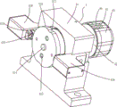
Fig. 1 is a schematic overall structure of an embodiment of the present invention.
Fig. 2 is a schematic structural diagram of a positioning device according to an embodiment of the invention.
Fig. 3 is a cross-sectional view of a positioning device in an embodiment of the invention.
Fig. 4 is a schematic structural diagram of a turnover device according to an embodiment of the present invention.
Fig. 5 is a schematic structural diagram of a first gilding structure or a second gilding structure in an embodiment of the invention.
Fig. 6 is a schematic structural diagram of an upper and lower feeding device in an embodiment of the present invention.
Detailed Description
The invention is described in further detail below with reference to the attached drawings and detailed description: referring to fig. 1 to 6, an automatic stamping machine comprises a base 1, wherein a fixed plate 2 is arranged in the middle of the base 1, a rotating disc 3 which is controlled to rotate by a motor is arranged on the outer ring of the fixed plate 2, a plurality of positioning devices 4 are uniformly arranged on the rotating disc 3, and a feeding and discharging device 5, a first stamping structure 6, a turnover device 7 and a second stamping structure 8 are sequentially arranged on the fixed plate 2 or the base 1 along the rotating direction of the rotating disc 3; the positioning device 4 comprises a first positioning seat 41, a rotating piece 42 is rotatably arranged on the first positioning seat 41, a die 43 matched with a packaging bottle accommodating cavity is arranged at one end of the rotating piece 42, a guide hole 44 is radially arranged in the die 42, a clamping mechanism mounting cavity 45 communicated with the guide hole 44 is arranged in the rotating piece 42, a clamping piece 46 is arranged in the clamping mechanism mounting cavity 45, a first spring 47 is arranged between the two clamping pieces 46, the two clamping pieces 46 slide along the guide hole 44, a first inclined surface 48 is arranged on the two clamping pieces 46, a radial guide groove 49 is arranged in the clamping mechanism mounting cavity 45, a driving frame 410 is arranged in the radial guide groove 49 in a sliding manner, a second inclined surface 411 matched with the first inclined surface 48 is arranged in the driving frame 410, a spring seat 412 is arranged in the clamping mechanism mounting cavity 45 inside the driving frame 410, a second spring 413 is arranged between the spring seat 412 and the driving frame 410, a driving frame 414 is fixedly arranged on the driving frame 414 and extends out of the guide rod 9 when the driving frame 414 is used for pushing the driving rod 45 to move towards the inner end face of the driving rod 9, and the driving rod 44 is fixedly arranged in the driving rod 9; the feeding and discharging device 5 comprises a second positioning seat 51, a pneumatic sliding rail 52 is arranged on the second positioning seat 51, a feeding and discharging support 53 is arranged on the pneumatic sliding rail 52, two first rotating cylinders 54 are arranged on the feeding and discharging support 53 side by side, feeding and discharging cylinders 55 are arranged on rotating shafts of the two first rotating cylinders 54, and suction cups (not shown in the figure) are arranged on cylinder rods of the feeding and discharging cylinders 55; the first gold stamping structure 6 comprises a third positioning seat 61, a lifting cylinder 62 and a hot stamping template 63 positioned on a cylinder rod of the lifting cylinder 62, wherein rotary material rods 65 are arranged on the third positioning seat 61 on two sides of the hot stamping template 63, and a material driving rod 66 is arranged on the third positioning seat 61 on one side of the hot stamping template 63; the turnover device 7 comprises a fourth positioning seat 71, a driving and reversing cylinder 72 is arranged on the fourth positioning seat 71, a sliding connecting block 73 is arranged on a cylinder rod of the driving and reversing cylinder 72, a second rotating cylinder 74 is arranged on the sliding connecting block 73, a first synchronous pulley 75 is arranged on a cylinder rod of the second rotating cylinder 74, a second synchronous pulley 76 is rotatably arranged on the sliding connecting block 73, the first synchronous pulley 75 and the second synchronous pulley 76 are driven by a synchronous belt, a deflector rod 77 is arranged on the end face of the second synchronous pulley 76, and an inserting hole 415 for the deflector rod 77 to be inserted into to drive the rotating piece 42 to rotate is arranged on one end face of the rotating piece 42; the second gilding structure 8 is identical to the first gilding structure 6 in structure. When the automatic stamping machine is used, the pneumatic slide rail drives the feeding and discharging support to move, the sucking disc on one side moves to the material taking position, the first rotary cylinder rotates to match with the feeding and discharging cylinder to suck the packaging bottle which is not stamped, the first rotary cylinder rotates to match with the feeding and discharging cylinder to take down the packaging bottle which is stamped from the positioning device, then the pneumatic slide rail drives the feeding and discharging support to move, the packaging bottle which is not stamped is moved to the feeding position to be sleeved on the positioning device, the packaging bottle which is stamped is placed on the finished product material position, the feeding position and the finished product material position are both provided with conveying belts for automatic feeding and automatic discharging of the finished product material, and the clamping cylinder is required to match with a driving rod to push or loosen in the feeding and discharging process so that the clamping piece loosens or clamps the packaging bottle; the method comprises the steps that after a gilded packaging bottle is taken down and a gilded packaging bottle is arranged, a rotating disc rotates once, the gilded packaging bottle rotates to the position below a first gilded structure to carry out gilding operation once, after the gilded packaging bottle is completed, the gilded packaging bottle rotates to the position of a turnover device once, a driving-reversing cylinder stretches out to insert a shifting rod into a jack of a rotating piece, then the rotating piece rotates 180 degrees through rotation of a second rotating cylinder, and the second gilding device can be aligned to the position of the packaging bottle, which needs gilding next time; and then, continuously rotating the packaging bottle below the second stamping device, continuously executing one-time stamping operation by the second stamping device, and then, rotating the packaging bottle to the feeding and discharging support to discharge, namely, completing one-time stamping operation, wherein the packaging bottle is positioned on each positioning device in the processing process, and continuously and simultaneously processing.
The outer side of the rotating member 42 is provided with a convex ring 416, two opposite sides of the convex ring 416 are provided with concave portions 417, the first positioning seat 41 positioned at two opposite sides of the convex ring 416 is provided with a guide housing 418, a sliding block 419 is slidably arranged in the guide housing 418, a roller 420 is arranged on the sliding block 419, a third spring (not visible in the figure) is arranged between the sliding block 419 and the bottom of the guide housing 418, and the roller 420 abuts against the convex ring 416. The roller is clamped into the concave part by the elasticity of the third spring when the structure is adopted for stamping, so that the rotating piece on the positioning device is stable in position and is not easy to naturally rotate, the stamping position is more accurate, and the precision is higher.
The first gold stamping structure 6 is provided with a pushing cylinder 67 for pushing the packaging bottles. When the structure is adopted for gold stamping, the end part of the packaging bottle is tightly propped against the die through the pushing cylinder, so that the gold stamping precision is prevented from being influenced by looseness.
The base 1 is provided with a control panel 10, a box 11 is arranged below the base 1, and a driving structure for driving the rotating disc 3 to rotate is arranged in the box 11. The structure is adopted to enable the driving structure to be hidden in the box body, so that the safety is improved, and the control panel is arranged on the base to be convenient to control. The driving structure is a conventional driving mechanism with a motor driving gear transmission or belt transmission.
The direction of the guide hole 44 on the same rotating member 42 is the same as the direction of the connecting line of the recess 417. The roller is arranged on two sides of the first positioning seat, and the clamping piece is used for positioning the packaging bottle through the elastic force of the first spring, so that the clamping piece is preferably ensured on two sides of the packaging bottle when the roller enters the concave part to position the rotating piece, and the phenomenon that the packaging bottle is loosened and the gold stamping precision is influenced due to the fact that the clamping piece is pressed forward by the gold stamping machine is prevented.
Claims (5)
1. The utility model provides an automatic gilding press, includes base (1), base (1) middle part is equipped with fixed plate (2), fixed plate (2) outer lane is provided with through motor control pivoted rolling disc (3), its characterized in that: a plurality of positioning devices (4) are uniformly arranged on the rotating disc (3), and a feeding and discharging device (5), a first gold stamping structure (6), a turnover device (7) and a second gold stamping structure (8) are sequentially arranged on the fixed plate (2) or the base (1) along the rotating direction of the rotating disc (3); the positioning device (4) comprises a first positioning seat (41), a rotating piece (42) is rotatably arranged on the first positioning seat (41), a die (43) matched with a packaging bottle accommodating cavity is arranged at one end of the rotating piece (42), a guide hole (44) is radially arranged in the die (43), a clamping mechanism mounting cavity (45) communicated with the guide hole (44) is arranged in the rotating piece (42), a clamping piece (46) is arranged in the clamping mechanism mounting cavity (45), a first spring (47) is arranged between the two clamping pieces (46), the two clamping pieces (46) slide along the guide hole (44), a first inclined surface (48) is arranged on the two clamping pieces (46), a radial guide groove (49) is arranged in the clamping mechanism mounting cavity (45), a driving frame (410) is arranged in the radial guide groove (49), a second inclined surface (45) matched with the first inclined surface (48) is arranged in the driving frame (410), a second inclined surface (412) matched with the first inclined surface (411) is arranged in the driving frame (412), a spring seat (410) is arranged in the driving frame (412), a driving rod (414) extending out of the end face of the rotating member (42) is fixed on the driving frame (410), when the driving rod (414) is pressed into the clamping mechanism mounting cavity (45), the clamping member (46) moves towards the inner direction of the guide hole (44), and a clamping cylinder (9) for pushing the driving rod (414) is arranged on the fixed plate (2); the feeding and discharging device (5) comprises a second positioning seat (51), a pneumatic sliding rail (52) is arranged on the second positioning seat (51), a feeding and discharging support (53) is arranged on the pneumatic sliding rail (52), two first rotating cylinders (54) are arranged on the feeding and discharging support (53) side by side, feeding and discharging cylinders (55) are arranged on rotating shafts of the two first rotating cylinders (54), and suction discs are arranged on cylinder rods of the feeding and discharging cylinders (55); the first gold stamping structure (6) comprises a third positioning seat (61), a lifting cylinder (62) and a hot stamping template (63) positioned on a cylinder rod of the lifting cylinder (62), wherein rotary material rods (65) are arranged on the third positioning seats (61) on two sides of the hot stamping template (63), and a material driving rod (66) is arranged on the third positioning seat (61) on one side of the hot stamping template (63); the turnover device (7) comprises a fourth positioning seat (71), an advancing and retreating cylinder (72) is arranged on the fourth positioning seat (71), a sliding connecting block (73) is arranged on a cylinder rod of the advancing and retreating cylinder (72), a second rotating cylinder (74) is arranged on the sliding connecting block (73), a first synchronous pulley (75) is arranged on a cylinder rod of the second rotating cylinder (74), a second synchronous pulley (76) is rotatably arranged on the sliding connecting block (73), the first synchronous pulley (75) and the second synchronous pulley (76) are driven by a synchronous belt, a deflector rod (77) is arranged on the end face of the second synchronous pulley (76), and an inserting hole (415) for the deflector rod (77) to be inserted into and driven by one end face of the rotating piece (42) to rotate is formed; the second gold stamping structure (8) is identical to the first gold stamping structure (6), and a clamping cylinder is required to be matched to push or loosen a driving rod in the feeding and discharging process so that a clamping piece can loosen or clamp the packaging bottle; the method comprises the steps that after a gilded packaging bottle is taken down and a gilded packaging bottle is arranged, a rotating disc rotates once, the gilded packaging bottle rotates to the position below a first gilded structure to carry out gilding operation once, after the gilded packaging bottle is completed, the gilded packaging bottle rotates to the position of a turnover device once, a driving-reversing cylinder stretches out to insert a shifting rod into a jack of a rotating piece, then the rotating piece rotates 180 degrees through rotation of a second rotating cylinder, and the second gilding device can be aligned to the position of the packaging bottle, which needs gilding next time; and then continuously rotating the packaging bottle to the lower part of the second gold stamping device, continuously executing gold stamping operation once by the second gold stamping device, and then rotating the packaging bottle to the feeding and discharging support for discharging.
2. An automatic stamping machine as claimed in claim 1, wherein: the rotary part (42) outside is provided with bulge loop (416), bulge loop (416) opposite both sides are provided with depressed part (417), are located bulge loop (416) opposite both sides be provided with direction casing (418) on first positioning seat (41), the slip is provided with slider (419) in direction casing (418), be provided with gyro wheel (420) on slider (419), slider (419) with be provided with the third spring between direction casing (418) bottom, gyro wheel (420) are propped against bulge loop (416).
3. An automatic stamping machine as claimed in claim 1, wherein: the first gold stamping structure (6) is provided with a pushing cylinder (67) for pushing against the packaging bottles.
4. An automatic stamping machine as claimed in claim 1, wherein: the novel rotary disc comprises a base (1), wherein a control panel (10) is arranged on the base (1), a box body (11) is arranged below the base (1), and a driving structure for driving the rotary disc (3) to rotate is arranged in the box body (11).
5. An automatic stamping machine as claimed in claim 2, wherein: the direction of the guide hole (44) on the same rotating member (42) is the same as the direction of the connecting line of the concave part (417).
Priority Applications (1)
| Application Number | Priority Date | Filing Date | Title |
|---|---|---|---|
| CN201810853968.7A CN108688309B (en) | 2018-07-30 | 2018-07-30 | Automatic gilding press |
Applications Claiming Priority (1)
| Application Number | Priority Date | Filing Date | Title |
|---|---|---|---|
| CN201810853968.7A CN108688309B (en) | 2018-07-30 | 2018-07-30 | Automatic gilding press |
Publications (2)
| Publication Number | Publication Date |
|---|---|
| CN108688309A CN108688309A (en) | 2018-10-23 |
| CN108688309B true CN108688309B (en) | 2023-07-04 |
Family
ID=63851862
Family Applications (1)
| Application Number | Title | Priority Date | Filing Date |
|---|---|---|---|
| CN201810853968.7A Active CN108688309B (en) | 2018-07-30 | 2018-07-30 | Automatic gilding press |
Country Status (1)
| Country | Link |
|---|---|
| CN (1) | CN108688309B (en) |
Families Citing this family (1)
| Publication number | Priority date | Publication date | Assignee | Title |
|---|---|---|---|---|
| CN110774748B (en) * | 2019-10-31 | 2024-12-03 | 浙江万得福智能科技股份有限公司 | A turntable hot stamping machine |
Citations (5)
| Publication number | Priority date | Publication date | Assignee | Title |
|---|---|---|---|---|
| CN201552805U (en) * | 2009-11-30 | 2010-08-18 | 龚肖新 | Automatic feeding mechanism of bronzing machine |
| CN105291583A (en) * | 2015-11-04 | 2016-02-03 | 江苏坤泰机械有限公司 | Full automatic two-color synchronous efficient stamping machine |
| CN105751684A (en) * | 2016-04-28 | 2016-07-13 | 浙江特美新材料股份有限公司 | Alumite gold stamping device of two-color gold stamping machine |
| CN206406406U (en) * | 2017-01-10 | 2017-08-15 | 浙江瑞昶实业有限公司 | A kind of outer assistant cooling structure of mould |
| CN206781247U (en) * | 2017-03-16 | 2017-12-22 | 东莞第一精工模塑有限公司 | A self-cleaning three-dimensional bronzing machine |
-
2018
- 2018-07-30 CN CN201810853968.7A patent/CN108688309B/en active Active
Patent Citations (5)
| Publication number | Priority date | Publication date | Assignee | Title |
|---|---|---|---|---|
| CN201552805U (en) * | 2009-11-30 | 2010-08-18 | 龚肖新 | Automatic feeding mechanism of bronzing machine |
| CN105291583A (en) * | 2015-11-04 | 2016-02-03 | 江苏坤泰机械有限公司 | Full automatic two-color synchronous efficient stamping machine |
| CN105751684A (en) * | 2016-04-28 | 2016-07-13 | 浙江特美新材料股份有限公司 | Alumite gold stamping device of two-color gold stamping machine |
| CN206406406U (en) * | 2017-01-10 | 2017-08-15 | 浙江瑞昶实业有限公司 | A kind of outer assistant cooling structure of mould |
| CN206781247U (en) * | 2017-03-16 | 2017-12-22 | 东莞第一精工模塑有限公司 | A self-cleaning three-dimensional bronzing machine |
Also Published As
| Publication number | Publication date |
|---|---|
| CN108688309A (en) | 2018-10-23 |
Similar Documents
| Publication | Publication Date | Title |
|---|---|---|
| CN202400345U (en) | Labeling machine | |
| CN208745529U (en) | A kind of two-sided gold stamping positioning device of automatic hot foil printing machine | |
| CN108688309B (en) | Automatic gilding press | |
| CN109160020B (en) | Full-automatic insole hot stamping machine | |
| CN108674076B (en) | Automatic gilding press double-sided gilding positioner | |
| CN108068452B (en) | Gold stamping device | |
| CN113715346B (en) | Integrated gum forming preparation method for special-shaped structural part | |
| CN208558617U (en) | A kind of automatic hot foil printing machine | |
| US6634404B2 (en) | Set-down box | |
| CN106739608B (en) | A kind of anti-fake mark production method and device based on laser scanning | |
| CN210942638U (en) | Flexible labeller of lamp body | |
| CN210337261U (en) | Double-sided gold stamping positioning device of automatic gold stamping machine | |
| CN209634854U (en) | A kind of four sides automatic labeling equipment | |
| CN210556075U (en) | Labeling machine | |
| JP3515609B2 (en) | Labeling machine | |
| CN109625516B (en) | Bottom label high-precision rolling and pasting mechanism | |
| CN211335112U (en) | Full-automatic gilding device | |
| CN210162395U (en) | But angle of adjustment's full-automatic labeller | |
| CN205943780U (en) | Full -automatic electric capacity trimmer | |
| CN218505488U (en) | Gilt printing device of high colour fastness cotton flannel | |
| CN216942291U (en) | Full-automatic gilding press carousel based on multistation | |
| CN215852339U (en) | Reliable and stable high-speed wide-label station | |
| CN221563781U (en) | Lipstick bottle is labeller for labeling | |
| CN217554427U (en) | Automatic round bottle labeling machine | |
| CN114932746B (en) | Multi-station rapid gilding press |
Legal Events
| Date | Code | Title | Description |
|---|---|---|---|
| PB01 | Publication | ||
| PB01 | Publication | ||
| SE01 | Entry into force of request for substantive examination | ||
| SE01 | Entry into force of request for substantive examination | ||
| GR01 | Patent grant | ||
| GR01 | Patent grant |