Detailed Description
The technical solutions in the embodiments of the present application will be clearly and completely described below with reference to the drawings in the embodiments of the present application. It is to be understood that the embodiments described are only a few embodiments of the present application and not all embodiments. All other embodiments, which can be derived by a person skilled in the art from the embodiments given herein without making any creative effort, shall fall within the protection scope of the present application.
In the description of the present application, it is to be understood that the terms "center," "longitudinal," "lateral," "length," "width," "thickness," "upper," "lower," "front," "rear," "left," "right," "vertical," "horizontal," "top," "bottom," "inner," "outer," "clockwise," "counterclockwise," and the like are used in the orientations and positional relationships indicated in the drawings for convenience in describing the present application and for simplicity in description, and are not intended to indicate or imply that the referenced devices or elements must have a particular orientation, be constructed in a particular orientation, and be operated in a particular manner, and are not to be construed as limiting the present application. Furthermore, the terms "first", "second" and "first" are used for descriptive purposes only and are not to be construed as indicating or implying relative importance or implicitly indicating the number of technical features indicated. Thus, features defined as "first", "second", may explicitly or implicitly include one or more of the described features. In the description of the present application, "a plurality" means two or more unless specifically limited otherwise.
In the description of the present application, it is to be noted that, unless otherwise explicitly specified or limited, the terms "mounted," "connected," and "connected" are to be construed broadly, e.g., as meaning either a fixed connection, a removable connection, or an integral connection; may be mechanically connected, may be electrically connected or may be in communication with each other; either directly or indirectly through intervening media, either internally or in any other relationship. The specific meaning of the above terms in the present application can be understood by those of ordinary skill in the art as appropriate.
In this application, unless expressly stated or limited otherwise, the first feature "on" or "under" the second feature may comprise direct contact of the first and second features, or may comprise contact of the first and second features not directly but through another feature in between. Also, the first feature being "on," "above" and "over" the second feature includes the first feature being directly on and obliquely above the second feature, or merely indicating that the first feature is at a higher level than the second feature. A first feature being "under," "below," and "beneath" a second feature includes the first feature being directly under and obliquely below the second feature, or simply meaning that the first feature is at a lesser elevation than the second feature.
The following disclosure provides many different embodiments or examples for implementing different features of the application. In order to simplify the disclosure of the present application, specific example components and arrangements are described below. Of course, they are merely examples and are not intended to limit the present application. Moreover, the present application may repeat reference numerals and/or letters in the various examples, such repetition is for the purpose of simplicity and clarity and does not in itself dictate a relationship between the various embodiments and/or configurations discussed. In addition, examples of various specific processes and materials are provided herein, but one of ordinary skill in the art may recognize applications of other processes and/or use of other materials.
The embodiment of the application provides an antenna assembly, a manufacturing method of the antenna assembly and electronic equipment.
Referring to fig. 1, fig. 1 is a schematic view of a first structure of an electronic device according to an embodiment of the present disclosure. The electronic device 10 may include a cover 11, a display 12, a driving circuit 13, a battery 14, a housing 15, a front camera 161, a rear camera 162, a fingerprint unlock module 17, and an antenna structure 19. It should be noted that the electronic device 10 shown in fig. 1 is not limited to the above, and may also include other devices, or does not include the front camera 161, or does not include the rear camera 162, or does not include the fingerprint unlocking module 17.
Wherein the cover plate 11 is mounted to the display screen 12 to cover the display screen 12. The cover 1 may be a transparent glass cover so that the display screen transmits light through the cover 11 to display. In some embodiments, the cover plate 11 may be a glass cover plate made of a material such as sapphire.
Wherein the housing 15 may form an outer contour of the electronic device 10. In some embodiments, the housing 15 may include a middle frame 151 and a rear cover 152, the middle frame 151 and the rear cover 152 may be combined with each other to form the housing 15, and the middle frame 151 and the rear cover 152 may form a receiving space to receive the driving circuit 13, the display 12, the battery 14, and the like. Further, the cover plate 11 may be fixed to the case 15, and the cover plate 11 and the case 15 form a closed space to accommodate the driving circuit 13, the display 12, the battery 14, and the like. In some embodiments, the cover plate 11 is disposed on the middle frame 151, the rear cover 152 is disposed on the middle frame 151, the cover plate 11 and the rear cover 152 are disposed on opposite sides of the middle frame 151, and the cover plate 11 and the rear cover 152 are disposed opposite to each other.
In some embodiments, the housing 15 may be a metal housing, such as a metal such as magnesium alloy, stainless steel, and the like. It should be noted that the material of the housing 15 in the embodiment of the present application is not limited to this, and other manners may also be adopted, such as: the housing 15 may be a plastic housing. Also for example: the housing 15 is a ceramic housing. For another example: the housing 15 may include a plastic part and a metal part, and the housing 15 may be a housing structure in which metal and plastic are matched with each other, specifically, the metal part may be formed first, for example, a magnesium alloy substrate is formed by injection molding, and then plastic is injected on the magnesium alloy substrate to form a plastic substrate, so as to form a complete housing structure. The material and process of the case 15 are not limited to this, and a glass case may be used.
It should be noted that, the structure of the housing in the embodiment of the present application is not limited to this, for example: the rear cover and the middle frame are integrally formed to form a completed housing 15 structure, which directly has a receiving space for receiving the driving circuit 13, the display 12, the battery 14, and the like.
The driving circuit 13 is installed in the housing 15, the driving circuit 13 may be a motherboard of the electronic device 10, and one, two or more functional components of a motor, a microphone, a speaker, an earphone interface, a universal serial bus interface, a front camera 161, a rear camera 162, a distance sensor, an ambient light sensor, a receiver, and a processor may be integrated on the driving circuit 13.
In some embodiments, the drive circuit 13 may be fixed within the housing 15. Specifically, the driving circuit 13 may be screwed to the middle frame 151 by a screw, or may be snap-fitted to the middle frame 151. It should be noted that the way that the driving circuit 13 is specifically fixed to the middle frame 151 in the embodiment of the present application is not limited to this, and other ways, such as a way of fixing by a snap and a screw together, may also be used.
Wherein the battery 14 is mounted in the housing 15, and the battery 14 is electrically connected to the driving circuit 13 to supply power to the electronic device 10. The housing 15 may serve as a battery cover for the battery 14. The case 15 covers the battery 14 to protect the battery 14, and particularly, the rear cover covers the battery 14 to protect the battery 14, reducing damage to the battery 14 due to collision, dropping, and the like of the electronic apparatus 10.
Wherein the antenna structure 19 is arranged on the housing 15. In some embodiments, the antenna structure 19 is disposed on the middle frame 151, which may increase the clearance area of the antenna structure 19 inside the electronic device 10 without changing the size of the electronic device 10.
Wherein the display 12 is mounted in the housing 15, and the display 12 is electrically connected to the driving circuit 13 to form a display surface of the electronic device 10. The display screen 12 may include a display area and a non-display area. The display area may be used to display a screen of the electronic device 10 or provide a user with touch control. The top area of the non-display area is provided with an opening for conducting sound and light, and the bottom of the non-display area can be provided with functional components such as a fingerprint module, a touch key and the like. The cover plate 11 is mounted on the display 12 to cover the display 12, and may form the same display area and non-display area as the display 12 or different display areas and non-display areas.
In some embodiments, the Display 12 may be a Liquid Crystal Display (LCD) or Organic Light-Emitting Diode (OLED) type Display. In some embodiments, when the display 12 is a liquid crystal display, the display 12 may include a backlight module, a lower polarizer, an array substrate, a liquid crystal layer, a color filter substrate, an upper polarizer, and the like, which are sequentially stacked. When the display 12 is an organic light emitting diode display, the display 12 may include a base layer, an anode layer, an organic layer, a conductive layer, an emission layer, and a cathode layer stacked in sequence. In some embodiments, the display 12 may be a transparent display, and the display 12 may have a transparent characteristic through which signals may pass. The display screen may also be a non-transparent display screen.
Note that the structure of the display screen 12 is not limited to this. For example, the display 12 may be a shaped screen.
Referring to fig. 2, fig. 2 is a second structural schematic diagram of an electronic device according to an embodiment of the present disclosure. The electronic device 20 comprises a display 22, a cover 21, a driver circuit 23, a battery 24, a housing 25 and an antenna structure 29. The electronic device 20 differs from the electronic device 10 in that: the display screen 22 has a light permeable area 28 formed directly thereon. Such as: the display screen 22 is provided with a through hole penetrating the display screen 22 in the thickness direction, the light permeable region 28 may include the through hole, and the through hole may be provided with functional components such as a front camera 161, an earpiece, a sensor, and the like.
It should be noted that the structure of the display screen is not limited to this, for example: the display screen 22 is provided with non-display areas, which non-display areas may be included in the light permeable area 28, which non-display areas are not displayed. It should be noted that, the housing 25 may refer to the housing 15, the driving circuit 23 may refer to the driving circuit 13, the battery 24 may refer to the battery 14, and the antenna structure 29 may refer to the antenna structure 19, which are not described herein again.
Referring to fig. 3, fig. 3 is a third structural schematic diagram of an electronic device according to an embodiment of the present disclosure, and the electronic device 30 in fig. 3 may include a display screen 32, a cover plate 31, a driving circuit 33, a battery 34, and a housing 35. This electronic device 30 differs from the above electronic devices in that: the display screen 32 is provided with a notch 321 at its periphery, and the notch 321 can be used for placing functional components such as the front camera 161, the receiver, and the sensor. The cover 31 is suitable for the structure of the display screen 31, the cover 31 may be provided with a large notch 321, and the cover 31 may cover the notch 321. It should be noted that, the housing 35 may refer to the housing 15, the driving circuit 33 may refer to the driving circuit 13, the battery 34 may refer to the battery 14, and the antenna structure 39 may refer to the antenna structure 19, which are not described herein again.
It should be noted that, in some embodiments, the display 12 may not include the non-display area, but may be configured as a full-screen structure, and the functional components such as the distance sensor and the ambient light sensor may be disposed below the display or at other positions. Specifically, please refer to fig. 4, where fig. 4 is a fourth structural schematic diagram of an electronic device according to an embodiment of the present disclosure. The electronic device 40 may include a display 42, a cover 41, a drive circuit 43, a battery 44, and a housing 45. Wherein the display screen 42 is overlaid on the housing 45 without a non-display area. Wherein, the cover plate 41 is suitable for the size setting of the display screen 42. It should be noted that, the housing 45 may refer to the housing 15, the driving circuit 43 may refer to the driving circuit 13, the battery 44 may refer to the battery 14, and the antenna structure 49 may refer to the antenna structure 19, which are not described herein again.
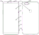
Referring to fig. 5, fig. 5 is a fifth structural schematic diagram of an electronic device according to an embodiment of the present disclosure. The electronic device may include an antenna including a first antenna structure and a second antenna structure.
Wherein, a first antenna 511 is formed at the first antenna 511 structure, a second antenna 512 is formed at the second antenna 512 structure, and the first antenna 511 and the second antenna 512 are oppositely arranged. Specifically, the first antenna 511 is used to implement a first data transceiving function; the second antenna 512 is used for implementing a second data transceiving function. The first data transceiving function is different from the second data transceiving function, so that the first antenna 511 and the second antenna 512 can perform different data transceiving functions at the same time.
It is understood that the first antenna 511 may also implement the second data transceiving function, and the second antenna 512 may also implement the first data transceiving function, which may be switched according to different scenarios.
The first data transceiving function and the second data transceiving function may be a WIFI communication function or an LTE communication function. Of course, in addition to the above functions, the first data transceiving function and the second data transceiving function may also be other data transceiving functions, which are not described herein again.
The electronic device may also include an object proximity sensor for determining a relative position of the object and the electronic device. Specifically, the object proximity sensor may be a pressure-sensitive sensor, an infrared distance sensor, a touch-sensitive sensor, an ultrasonic distance sensor, or a capacitive sensor, as long as the object proximity detection function can be achieved, and the application is not limited herein.
In some embodiments, the object proximity sensors are disposed on opposite sides of the housing. The object proximity sensors include a first object proximity sensor 521 and a second object proximity sensor 522. Wherein the first object proximity sensor 521 is disposed on the housing adjacent to the first antenna 511 and the second object proximity sensor 522 is disposed on the housing adjacent to the second antenna 512.
In other embodiments, the object proximity sensor may be multiplexed with an antenna of the electronic device, with the proximity of the object being inductively sensed by the antenna on the electronic device. Specifically, the first antenna 511 and the second antenna 512 may be multiplexed as an object proximity sensor. Wherein the first object proximity sensor 521 is multiplexed with the first antenna 511; the second object proximity sensor 522 is multiplexed with the second antenna 512. Of course, in the case of an electronic device having a multi-antenna structure, the multi-antenna may be used as a plurality of sensors to detect the approach of an object.
When the first object proximity sensor 521 and the second object proximity sensor 522 are disposed on the housing adjacent to the antenna, it may be determined whether an object is relatively close to the first object proximity sensor 521 or the second object proximity sensor 522 according to object proximity signals received by the different object proximity sensors, so as to determine a grip posture of the user according to a determination result, so as to determine where the unblocked antenna is.
Specifically, when it is required to determine whether an object is relatively close to the first object proximity sensor 521 or the second object proximity sensor 522, the following manner may be adopted for determination: acquiring a first proximity signal of a first object proximity sensor 521 and a second proximity signal of a second object proximity sensor 522; comparing the first proximity signal with the second proximity signal to obtain a comparison result; according to the comparison result, it is determined whether the object is relatively close to the first object proximity sensor 521 or the second object proximity sensor 522.
For example, when the first object proximity sensor 521 detects that an object is approaching, so that the value of the sensor is shown as 1, and the second object proximity sensor 522 does not detect that an object is approaching, so that the value of the sensor is shown as 0, the two values are compared to obtain that the second antenna 512 corresponding to the second object proximity sensor 522 is not shielded.
Of course, different object proximity sensors can generate different signal results, and the results generated by the first object proximity sensor 521 and the second object proximity sensor 522 can be respectively determined according to actual conditions, so as to more accurately determine the holding posture of the user.
On the other hand, the electronic device includes a driving circuit including an antenna switching circuit, which is configured to acquire data usage of the first data transceiving function and the second data transceiving function, and switch the current data transceiving function of the first antenna 511 and the second antenna 512 according to the relative position of the object and the electronic device and the data usage.
When the electronic device determines to adopt one of the data transceiving functions, it is possible that the other data transceiving function is temporarily idle or turned off, and it is possible to determine which data transceiving function the electronic device is using through the data usage of the first data transceiving function and the second data transceiving function.
In some embodiments, the data usage includes data traffic flow values per unit time length.
The unit time length can be any time length value in the historical use process, for example, a data flow value sent and/or received by the electronic equipment within one minute.
Specifically, when the data transceiving flow value of the first data transceiving function in the unit time length is greater than or equal to the first preset value and the object is relatively close to the first object proximity sensor 521, the first antenna 511 is switched to the second data transceiving function, and the second antenna 512 is switched to the first data transceiving function.
Or, when the data transceiving flow value of the second data transceiving function in the unit time length is greater than or equal to the second preset value and the object is relatively close to the second object proximity sensor 522, the first antenna 511 is switched to the second data transceiving function, and the second antenna 512 is switched to the first data transceiving function.
The holding posture condition of a user is determined through the sensor, the data transceiving function of the antenna is determined, the holding posture condition and the data transceiving function are combined, and compared with the method that the antenna is switched only by detecting the signal quality of the current antenna, the control switching of the current data transceiving function of the antenna can be more intelligently and effectively carried out according to different using scenes.
Therefore, the holding mode of the user on the electronic equipment is detected through the object proximity sensor, whether the current data transceiving function of the antenna is switched or not is determined by combining the data use condition of the antenna, the working mode of the antenna in the electronic equipment can be more intelligently and effectively adjusted according to the antenna use requirement of the current scene of the user, the antenna with less influence on the antenna transmission quality by the holding posture of the user is used as the main antenna used by the current data transceiving function, the transmission performance of the antenna for the data transceiving function is further improved, and the power consumption of the electronic equipment can be reduced.
Referring to fig. 6, a flow of implementing an antenna switching method according to an embodiment of the present application is shown. The method is applied to the electronic equipment shown in the figures 1-5 and comprises the following steps:
601. a relative position of the object and the electronic device is determined.
Wherein the relative position of the object and the electronic device is determined, which can be detected by using an object proximity sensor.
In some embodiments, the electronic device includes a first antenna structure and a second antenna structure. Specifically, the first antenna is used for realizing a first data transceiving function; the second antenna is used for realizing a second data transceiving function. The first data transceiving function is different from the second data transceiving function, so that the first antenna and the second antenna can respectively execute different data transceiving functions at the same time.
It can be understood that the first antenna may also implement the second data transceiving function, and the second antenna may also implement the first data transceiving function, and the data transceiving function may be switched according to different scenarios.
The first data transceiving function and the second data transceiving function may be a WIFI communication function or an LTE communication function. Of course, in addition to the above functions, the first data transceiving function and the second data transceiving function may also be other data transceiving functions, which are not described herein again.
In some embodiments, the object proximity sensors are disposed on opposite sides of the housing. The object proximity sensor includes a first object proximity sensor and a second object proximity sensor. Wherein the first object proximity sensor is disposed on the housing adjacent the first antenna and the second object proximity sensor is disposed on the housing adjacent the second antenna.
In other embodiments, the object proximity sensor may be multiplexed with an antenna of the electronic device, with the proximity of the object being inductively sensed by the antenna on the electronic device. Specifically, both the first antenna and the second antenna may be multiplexed as an object proximity sensor. Wherein the first object proximity sensor is multiplexed with the first antenna; the second object proximity sensor is multiplexed with the second antenna. Of course, in the case of an electronic device having a multi-antenna structure, the multi-antenna may be used as a plurality of sensors to detect the approach of an object.
When the first object proximity sensor and the second object proximity sensor are arranged on the shell adjacent to the antenna, whether the object is relatively close to the first object proximity sensor or the second object proximity sensor can be judged according to object proximity signals received by the different object proximity sensors, so that the holding posture of the user is determined according to the judgment result, and the antenna which is not blocked is determined.
Of course, different object proximity sensors can generate different signal results, and the results generated by the first object proximity sensor and the second object proximity sensor can be respectively judged according to actual conditions, so that the holding posture of the user can be more accurately determined.
602. And acquiring the data use conditions of the first data transceiving function and the second data transceiving function.
The data use condition of the first data transceiving function and the second data transceiving function can be checked from related values in a parameter list by calling the parameter list about the antenna state in the electronic equipment. Or detecting the working state of the antenna in real time, and determining the numerical value of the data use condition by using the detected result.
603. And switching the current data transceiving functions of the first antenna and the second antenna according to the relative position of the object and the electronic equipment and the data use condition.
When the electronic device determines to adopt one of the data transceiving functions, it is possible that the other data transceiving function is temporarily idle or turned off, and it is possible to determine which data transceiving function the electronic device is using through the data usage of the first data transceiving function and the second data transceiving function.
In some embodiments, the data usage includes data traffic flow values per unit time length.
The unit time length can be any time length value in the historical use process, for example, a data flow value sent and/or received by the electronic equipment within one minute. According to the data transceiving flow value in the unit time length, the data transceiving function mainly adopted at present can be determined.
For example, the data usage situations that can be invoked from the electronic device to the first data transceiving function and the second data transceiving function are respectively: the data transceiving traffic value of the first data transceiving function at the past 1 minute is 33M, and the data transceiving traffic value of the second data transceiving function at the past 1 minute is 0.01M, it is possible to determine that the data transceiving function currently used is the first data transceiving function by setting the preset value of 10M/minute.
When the currently used data transceiving function is determined to be the first data transceiving function, the current holding posture of the user can be referred to, data of the first object proximity sensor and data of the second object proximity sensor can be retrieved at the moment, and whether an object is relatively close to the first object proximity sensor or the second object proximity sensor can be determined by comparing the data of the two object proximity sensors. Of course, the determination step may precede the determination of whether the currently used data transceiving function is the first data transceiving function or the second data transceiving function.
Then, the relative position of the object and the electronic equipment and the data use condition are combined, the currently used data transceiving function is determined, and the data transceiving function is switched to the antenna which is not shielded by the body of the user, so that the antenna is used as a main antenna.
According to the embodiment, the holding posture condition of the user is determined through the sensor, the data transceiving function used by the antenna at present is determined, the holding posture condition and the data transceiving function are combined, and compared with the method that the antenna is switched only by detecting the signal quality of the antenna at present, the control switching of the current data transceiving function of the antenna can be more intelligently and effectively carried out according to different using scenes.
Referring to fig. 7, there are shown implementation steps for determining a position of an object according to an embodiment of the present application, where the implementation steps include:
701. a first proximity signal of a first object proximity sensor and a second proximity signal of a second object proximity sensor are acquired.
702. And comparing the first proximity signal with the second proximity signal to obtain a comparison result.
703. And judging whether the object is relatively close to the first object proximity sensor or the second object proximity sensor according to the comparison result.
For example, when the first object proximity sensor detects that an object is approaching, the value of the sensor is displayed as 1, and the second object proximity sensor does not detect that an object is approaching, and the value of the sensor is displayed as 0, the two values are compared, and the second antenna corresponding to the second object proximity sensor is obtained without being blocked.
By acquiring the first proximity signal of the first object proximity sensor and the second proximity signal of the second object proximity sensor and comparing the two signals, whether the object is relatively close to the first object proximity sensor or the second object proximity sensor can be accurately determined, and the processing efficiency of the electronic equipment on the object proximity condition is improved.
Specifically, when the data transceiving flow value of the first data transceiving function in unit time is greater than or equal to a first preset value and an object is relatively close to the first object proximity sensor, the first antenna is switched to the second data transceiving function, and the second antenna is switched to the first data transceiving function.
Or when the data transceiving flow value of the second data transceiving function in unit time length is larger than or equal to a second preset value and the object is relatively close to the second object proximity sensor, the first antenna is switched to the second data transceiving function, and the second antenna is switched to the first data transceiving function.
Therefore, the antenna with small influence on the antenna transmission quality by the holding posture of the user can be used as the main antenna used by the current data receiving and transmitting function, and the transmission performance of the antenna for the data receiving and transmitting function is improved, so that the judgment process is more intelligent and accurate.
Embodiments of the present application further provide a storage medium, where the storage medium stores a plurality of instructions, where the plurality of instructions are suitable for being loaded by a processor to perform the antenna switching method in the foregoing embodiments, for example: acquiring historical use conditions of the antenna, wherein the historical use conditions comprise at least one of the time length of the antenna serving as a main set antenna in a preset time period and the signal quality parameters of the antenna; determining a relative position of an object and the electronic device; acquiring data use conditions of a first data transceiving function and a second data transceiving function; and switching the current data transceiving functions of the first antenna and the second antenna according to the relative position of the object and the electronic equipment and the data use condition.
It should be noted that, as one of ordinary skill in the art would understand, all or part of the steps in the methods of the above embodiments may be implemented by hardware related to instructions of a program, and the program may be stored in a computer-readable medium, which may include but is not limited to: read Only Memory (ROM), Random Access Memory (RAM), magnetic or optical disks, and the like.
The electronic device and the antenna switching method provided in the embodiments of the present application are described in detail above, and specific examples are applied in the description to explain the principles and embodiments of the present application, and the description of the embodiments above is only used to help understanding the present application. Meanwhile, for those skilled in the art, according to the idea of the present application, there may be variations in the specific embodiments and the application scope, and in summary, the content of the present specification should not be construed as a limitation to the present application.