CN108353090B - Method for improving processing of sensor streaming data in a distributed network - Google Patents
Method for improving processing of sensor streaming data in a distributed network Download PDFInfo
- Publication number
- CN108353090B CN108353090B CN201680050011.8A CN201680050011A CN108353090B CN 108353090 B CN108353090 B CN 108353090B CN 201680050011 A CN201680050011 A CN 201680050011A CN 108353090 B CN108353090 B CN 108353090B
- Authority
- CN
- China
- Prior art keywords
- data
- sensor
- ingested
- network
- physical
- Prior art date
- Legal status (The legal status is an assumption and is not a legal conclusion. Google has not performed a legal analysis and makes no representation as to the accuracy of the status listed.)
- Active
Links
Images


Classifications
-
- H—ELECTRICITY
- H04—ELECTRIC COMMUNICATION TECHNIQUE
- H04L—TRANSMISSION OF DIGITAL INFORMATION, e.g. TELEGRAPHIC COMMUNICATION
- H04L67/00—Network arrangements or protocols for supporting network services or applications
- H04L67/50—Network services
- H04L67/56—Provisioning of proxy services
- H04L67/565—Conversion or adaptation of application format or content
-
- G—PHYSICS
- G05—CONTROLLING; REGULATING
- G05B—CONTROL OR REGULATING SYSTEMS IN GENERAL; FUNCTIONAL ELEMENTS OF SUCH SYSTEMS; MONITORING OR TESTING ARRANGEMENTS FOR SUCH SYSTEMS OR ELEMENTS
- G05B15/00—Systems controlled by a computer
- G05B15/02—Systems controlled by a computer electric
-
- G—PHYSICS
- G06—COMPUTING OR CALCULATING; COUNTING
- G06F—ELECTRIC DIGITAL DATA PROCESSING
- G06F8/00—Arrangements for software engineering
- G06F8/70—Software maintenance or management
-
- G—PHYSICS
- G06—COMPUTING OR CALCULATING; COUNTING
- G06F—ELECTRIC DIGITAL DATA PROCESSING
- G06F9/00—Arrangements for program control, e.g. control units
- G06F9/06—Arrangements for program control, e.g. control units using stored programs, i.e. using an internal store of processing equipment to receive or retain programs
- G06F9/46—Multiprogramming arrangements
- G06F9/54—Interprogram communication
- G06F9/542—Event management; Broadcasting; Multicasting; Notifications
-
- H—ELECTRICITY
- H04—ELECTRIC COMMUNICATION TECHNIQUE
- H04L—TRANSMISSION OF DIGITAL INFORMATION, e.g. TELEGRAPHIC COMMUNICATION
- H04L12/00—Data switching networks
- H04L12/28—Data switching networks characterised by path configuration, e.g. LAN [Local Area Networks] or WAN [Wide Area Networks]
- H04L12/2803—Home automation networks
- H04L12/2823—Reporting information sensed by appliance or service execution status of appliance services in a home automation network
-
- H—ELECTRICITY
- H04—ELECTRIC COMMUNICATION TECHNIQUE
- H04L—TRANSMISSION OF DIGITAL INFORMATION, e.g. TELEGRAPHIC COMMUNICATION
- H04L12/00—Data switching networks
- H04L12/28—Data switching networks characterised by path configuration, e.g. LAN [Local Area Networks] or WAN [Wide Area Networks]
- H04L12/2803—Home automation networks
- H04L12/283—Processing of data at an internetworking point of a home automation network
-
- H—ELECTRICITY
- H04—ELECTRIC COMMUNICATION TECHNIQUE
- H04L—TRANSMISSION OF DIGITAL INFORMATION, e.g. TELEGRAPHIC COMMUNICATION
- H04L12/00—Data switching networks
- H04L12/28—Data switching networks characterised by path configuration, e.g. LAN [Local Area Networks] or WAN [Wide Area Networks]
- H04L12/40—Bus networks
- H04L12/40006—Architecture of a communication node
-
- H—ELECTRICITY
- H04—ELECTRIC COMMUNICATION TECHNIQUE
- H04L—TRANSMISSION OF DIGITAL INFORMATION, e.g. TELEGRAPHIC COMMUNICATION
- H04L67/00—Network arrangements or protocols for supporting network services or applications
- H04L67/01—Protocols
- H04L67/12—Protocols specially adapted for proprietary or special-purpose networking environments, e.g. medical networks, sensor networks, networks in vehicles or remote metering networks
-
- H—ELECTRICITY
- H04—ELECTRIC COMMUNICATION TECHNIQUE
- H04L—TRANSMISSION OF DIGITAL INFORMATION, e.g. TELEGRAPHIC COMMUNICATION
- H04L67/00—Network arrangements or protocols for supporting network services or applications
- H04L67/2866—Architectures; Arrangements
- H04L67/2885—Hierarchically arranged intermediate devices, e.g. for hierarchical caching
-
- H—ELECTRICITY
- H04—ELECTRIC COMMUNICATION TECHNIQUE
- H04L—TRANSMISSION OF DIGITAL INFORMATION, e.g. TELEGRAPHIC COMMUNICATION
- H04L67/00—Network arrangements or protocols for supporting network services or applications
- H04L67/50—Network services
- H04L67/55—Push-based network services
-
- H—ELECTRICITY
- H04—ELECTRIC COMMUNICATION TECHNIQUE
- H04L—TRANSMISSION OF DIGITAL INFORMATION, e.g. TELEGRAPHIC COMMUNICATION
- H04L67/00—Network arrangements or protocols for supporting network services or applications
- H04L67/50—Network services
- H04L67/56—Provisioning of proxy services
- H04L67/561—Adding application-functional data or data for application control, e.g. adding metadata
-
- H—ELECTRICITY
- H04—ELECTRIC COMMUNICATION TECHNIQUE
- H04L—TRANSMISSION OF DIGITAL INFORMATION, e.g. TELEGRAPHIC COMMUNICATION
- H04L67/00—Network arrangements or protocols for supporting network services or applications
- H04L67/50—Network services
- H04L67/56—Provisioning of proxy services
- H04L67/562—Brokering proxy services
-
- H—ELECTRICITY
- H04—ELECTRIC COMMUNICATION TECHNIQUE
- H04L—TRANSMISSION OF DIGITAL INFORMATION, e.g. TELEGRAPHIC COMMUNICATION
- H04L12/00—Data switching networks
- H04L12/28—Data switching networks characterised by path configuration, e.g. LAN [Local Area Networks] or WAN [Wide Area Networks]
- H04L12/40—Bus networks
- H04L2012/4026—Bus for use in automation systems
Landscapes
- Engineering & Computer Science (AREA)
- Computer Networks & Wireless Communication (AREA)
- Signal Processing (AREA)
- Automation & Control Theory (AREA)
- General Engineering & Computer Science (AREA)
- Computing Systems (AREA)
- General Physics & Mathematics (AREA)
- Physics & Mathematics (AREA)
- Theoretical Computer Science (AREA)
- Software Systems (AREA)
- Health & Medical Sciences (AREA)
- Medical Informatics (AREA)
- General Health & Medical Sciences (AREA)
- Library & Information Science (AREA)
- Multimedia (AREA)
- Information Transfer Between Computers (AREA)
- Computer And Data Communications (AREA)
- Stored Programmes (AREA)
- Data Exchanges In Wide-Area Networks (AREA)
- Debugging And Monitoring (AREA)
Abstract
A method for implementing intelligence at an edge. The method is characterized by comprising the following steps: triggered by sensor data in a software layer hosted on the gateway device or embedded system. The software layer is connected to a local area network. A repository of services, applications and data processing engines is enabled to be accessed by the software layer. The sensor data is matched with a semantic description of the occurrence of a particular condition by an expression language provided by the software layer. Pattern events are automatically discovered by continuously executing expressions. Services and applications are intelligently orchestrated across gateway devices and embedded systems on the network managed by the software layer to link applications and analyze expressions. The layout of the application and analysis is optimized based on resource availability. The health of the software layer is monitored. Storing the raw sensor data or the results of the expression in a local time series database or cloud storage. Services and components may be containerized to ensure smooth operation in any gateway environment.
Description
Cross Reference to Related Applications
This patent application claims the benefit of U.S. patent application 62/210,981 filed on day 27/8/2015, which is incorporated herein by reference along with all other references cited in this application. U.S. patent applications 62/312,106, 62/312,187, 62/312,223, and 62/312,255, filed on 2016, 3, 23, are hereby incorporated by reference.
Background
The present invention relates to the field of computing, and more particularly, to edge computing for processing large amounts of data generated by industrial machines.
Traditional enterprise software application hosting relies on a data center or "cloud" infrastructure to exploit economies of scale and system efficiency. However, these data centers may be located any distance from the physical operating point (e.g., factory, warehouse, retail store, etc.) at which the enterprise performs most of the business operations. Industrial internet of things (IIoT) refers to a collection of devices or use cases that rely on physically operating instruments that utilize sensors that track events at very high frequencies.
Industrial machines belong to this internet of things (IoT) in many areas, including manufacturing, oil and gas, mining, transportation, power and water, renewable energy, healthcare, retail, smart building, smart cities, and interconnected vehicles. Although cloud computing has been successfully implemented, there are a number of drawbacks: sending all data to the cloud storage is not practical because the connection may not always exist, the bandwidth is insufficient, or even if there is enough bandwidth, the cost may be prohibitive. Even if connectivity, bandwidth, and cost are not issues, real-time decision making and predictive maintenance are not possible, which can lead to serious damage to the machine.
Accordingly, there is a need for improved computing systems, architectures, and techniques that include improved edge analysis in order to process large amounts of data generated by industrial machines.
Disclosure of Invention
A method for implementing intelligence at an edge. The method is characterized by comprising the following steps: triggered by sensor data in a software layer hosted on the gateway device or embedded system. The software layer is connected to a local area network. A repository of services, applications and data processing engines is enabled to be accessed by the software layer. The sensor data is matched with a semantic description of the occurrence of a particular condition by an expression language provided by the software layer. Pattern events are automatically discovered by continuously executing expressions. Services and applications are intelligently orchestrated across gateway devices and embedded systems on the network managed by the software layer to link applications and analyze expressions. The layout of the application and analysis is optimized based on resource availability. The health of the software layer is monitored. Storing the raw sensor data or the results of the expression in a local time series database or cloud storage. Services and components may be containerized to ensure smooth operation in any gateway environment.
Edge intelligence is enabled at an internet of things (IoT) data source. The system provides rich access (streaming mode or batch mode, or both) to IoT device sensor data for real-time edge analytics and applications. The system includes an efficient and expressive computer language for executing analysis functions and expressions by a high-performance analysis engine operating in a low-memory-footprint machine. The system allows publishing of aggregated data to the cloud for further machine learning. The system includes a software development kit for developing an edge application. The cloud-based management console allows for management of edge deployments, configurations, applications, and analytical expressions.
One implementation of an edge infrastructure and platform is from FogHorn Systems, Inc. Com, publications (including white papers, user guides, tutorials, videos, and other publications), and other publications relating to FogHorn technology and products are incorporated herein by reference.
FogHorn provides a platform to enable edge intelligence for industrial and commercial internet of things (IoT) data. Billions of industrial and commercial internet of things devices generate sufficient amounts of data to overwhelm the entire internet. The FogHorn platform processes, analyzes and responds to internet of things data originating from the edge of the network. The FogHorn's "intelligent edge" software platform achieves unprecedented degrees of automation, operational efficiency, cost savings, and the like.
Industrial internet of things (IIoT) consists of interconnected industrial and commercial equipment, such as sensors, machinery and computers. The goal of IIoT is to achieve better device control, data management, machine automation, and job efficiency in distributed enterprises. Companies can apply fog computing at the edge to capture IIoT greenfield opportunities with real-time analysis and automated responses, while also managing and optimizing the entire system with cloud computing. The FogHorn edge computing platform is also designed to run in existing Programmable Logic Controllers (PLCs) (e.g., brown land opportunities) if adding additional computing resources is not feasible. Brown means that new systems are implemented in order to solve the Information Technology (IT) problem area, but already established systems are also considered. The new software architecture takes into account both existing and running software.
The edge intelligence platform is a software-based solution based on the concept of fog computing that extends data processing and analysis closer to the edge where the IIoT device is located. Keeping close to the edge devices rather than sending all the data to a remote centralized cloud minimizes delays, resulting in optimal performance, faster response times, and more efficient maintenance and operation strategies. This approach also significantly reduces the overall bandwidth requirements and the cost of managing a widely distributed network.
The focus on IIoT operation at the edge reduces overall bandwidth requirements and enables immediate automatic response to time-sensitive conditions. With the increase of billions of new IIoT devices in the industry, a large amount of PB-level data is generated every day. Sending all of this data to the cloud is not only costly, but also comes with greater security concerns. Operating at the edge may ensure faster response times, lower risks, and lower overall costs.
In an embodiment, an edge computing platform system comprises: a number of sensor data streams and a software layer physically disposed between the sensors and the communication network, the software layer configured to perform calculations based on raw data received from the sensors. From the perspective of the data processing layer and the communication network, the software layer may include programmable virtual sensors.
The software may include a data processing layer that includes a complex event processing engine and an expression language for stream processing. The data processing layer may include a data enrichment layer and a software development kit for interacting with and developing applications. The software may include a data distribution layer to distribute sensor data streams or data or metadata derived from expressions in at least one of a local time series database or a selected cloud storage provider.
The system may include an application library, wherein the software layer is configured to store, retrieve, and deploy applications from the application library. The application is configured to process the sensor data at a hardware layer. The application library is configured to customize the application container based on resources available at the hardware layer.
In an embodiment, a sensor system comprises: a plurality of sensors; and a hardware layer physically disposed between the sensor and the communication network, the hardware layer configured to perform calculations based on raw data received from the sensor. From the perspective of the communication network, the hardware layer may be configured to be programmable as a virtual sensor. The virtual sensor may include an Application Program Interface (API) specified by programming in the hardware layer.
The system may include an application library, wherein the hardware layer is configured to receive the application from the application library. The application is configured to process sensor data on the hardware layer. The application library is configured to customize the application container based on resources available at the hardware layer.
In an embodiment, a method comprises: receiving sensor data flow data over a first network connection type at a data ingestion agent of an edge platform system; transmitting the ingested streaming data from the data ingest agent to a data bus of the system; processing the ingested streaming data at an analytics engine connected to (e.g., subscribing to data from) the data bus, wherein the processing includes executing an analytics expression provided in an expression language to generate intelligent information from the ingested streaming data; and issues intelligent information on the data bus. The method can comprise the following steps: the ingested data is enriched in real time by the data enrichment component and made available on the data bus. Enrichment may include, but is not limited to: data decoding, metadata modification, data normalization, and the like.
The method can comprise the following steps: receiving intelligent information from a data bus at a data publisher component; and storing the intelligent information in a time series database through the data publisher component. Further, the method may include communicating and storing, by the data publisher component, at least a portion of the intelligent information in the cloud storage via a second network connection type, wherein the second network connection type is different from the first network connection type, and the second network connection type has a lower bandwidth connection to the sensor data flow data than the first network connection type.
For example, the first network connection type may use an industrial IoT protocol, such as MQTT, OPC unified architecture, or Modbus protocols, as well as custom protocols. The second network connection type may use an internet protocol, such as TCP/IP, hypertext transfer protocol (HTTP), WebSockets, WebHDFS, or Apache Kafka, or any combination of these. The second network connection type may also use the protocol described above for the first network connection type.
The data ingest agent may access the sensor data stream data via a push protocol over the first network connection type. The data ingestion agent may also access the sensor data stream data via a pull protocol over the first network connection type.
The method can comprise the following steps: providing a software development kit that allows a user to develop applications for the edge platform system; and developing, by the software development kit, a first containerized application that can access and process the intelligence information available on the data bus. The method can comprise the following steps: receiving intelligent information from a data bus at a data publisher component; storing the intelligent information in a time series database through a data publisher component; and developing, by the software development kit, a second containerized application that can access and process the intelligence information stored in the time series database.
The method can comprise the following steps: an application store of the edge platform system is provided, wherein the first containerized application and the second containerized application are accessible to other users through the application store.
A first containerized application may be run within the edge platform system, where the first containerized application has a direct connection to the data bus. A first containerized application (without modification) may also be run in the cloud environment, where the first containerized application does not have a direct connection to the data bus, but rather accesses the intelligent information through a second network connection type.
The method can comprise the following steps: a first virtual sensor is created using an expression language, the first virtual sensor having a first input connected to a first physical sensor and a first output that is a first function of the first input. The first function is specified in an expression language. The first virtual sensor receives first stream data from the first physical sensor. At a first output, a first virtual sensor operates on first stream data according to a first function to output second stream data. The intelligent information includes the second stream data.
The method can comprise the following steps: a first virtual sensor is created using an expression language, the first virtual sensor having a first input connected to a first physical sensor, a second input connected to a second physical sensor, and a first output that is a first function of the first input and the second input. The first function is specified in an expression language. The first virtual sensor receives first stream data from the first physical sensor and second stream data from the second physical sensor. At a first output, a first virtual sensor operates on the first stream data and the second stream data according to a first function to output third stream data. The intelligence information includes the third stream data.
In an embodiment, a method comprises: receiving sensor data flow data over a first network connection type at a data ingestion agent of an edge platform system; transmitting the ingested streaming data from the data ingest agent to a data bus of the system; processing the ingested stream data at an analytics engine connected to the data bus, wherein the processing includes executing an analytics expression provided in an expression language to generate intelligent information from the ingested stream data; and providing a first virtual sensor having an input connected to the first physical sensor and an output that is a first function of the input, wherein the first function is specified in the expression language, the first virtual sensor accepts first stream data from the first physical sensor and at the output, the first virtual sensor operates on the first stream data according to the first function to output second stream data, and the intelligent information includes the second stream data.
The method further comprises the following steps: providing a second virtual sensor having a first input connected to a second physical sensor, a second input connected to the output of the first virtual sensor, and an output that is a second function of the first input and the second input, wherein the second function is specified in an expression language, the second virtual sensor receives third stream data from the second physical sensor and second stream data from the first virtual sensor, and at the first output, the second virtual sensor operates on the second stream data and the third stream data according to the second function to output fourth stream data, and the smart information includes the fourth stream data; issuing intelligent information on a data bus; receiving intelligent information from a data bus at a data publisher component; and storing the intelligent information in a time series database through the data publisher component.
In an embodiment, a method comprises: specifying a first virtual sensor in an expression language of an edge platform, wherein the first virtual sensor includes an output that is a first function of an input, wherein the first input is connected to a first stream of first physical sensors, and the first virtual sensor outputs a second stream; and allowing a second virtual sensor to be specified in the expression language, wherein the second virtual sensor includes an output that is a second function of the first input and the second input, wherein the first input is connected to the second stream of the second physical sensor and the second input is connected to the second stream from the first virtual sensor.
Other objects, features, and advantages of the present invention will become apparent upon consideration of the following detailed description and the accompanying drawings, in which like reference numerals refer to similar features throughout the figures.
Drawings
Fig. 1 shows a block diagram of a client-server system and a network.
Fig. 2 shows a more detailed diagram of a client or server.
FIG. 3 illustrates a system block diagram of a computer system.
FIG. 4 is a block diagram of an edge computing platform located between a sensor stream and a cloud.
FIG. 5 shows a more detailed block diagram of an edge computing platform including edge analysis.
Fig. 6 illustrates an operational flow between an edge infrastructure and a cloud infrastructure.
FIG. 7 illustrates an example of using physical sensors to create some virtual sensors via a sensor expression language engine.
Detailed Description
FIG. 1 is a simplified block diagram of a distributed computer network 100 including an embodiment of the present invention. Computer network 100 includes several client systems 113, 116, and 119 and a server system 122 coupled to a communication network 124 via a plurality of communication links 128. Communication network 124 provides a mechanism that allows the various components of distributed network 100 to communicate and exchange information with one another.
The communication network 124 itself may be comprised of many interconnected computer systems and communication links. The communication link 128 may be a hardwired link, an optical link, a satellite or other wireless communication link, a wave propagation link, or any other mechanism for communication of information. The communication link 128 may be a DSL, cable, ethernet or other hardwired link, passive or active optical link, 3G, 3.5G, 4G and other mobile, satellite or other wireless communication links, wave propagation links, or any other mechanism for communication of information.
Various communication protocols may be used to facilitate communications between the various systems shown in fig. 1. These communication protocols may include VLAN, MPLS, TCP/IP, network tunneling, HTTP protocols, Wireless Application Protocol (WAP), vendor specific protocols, custom protocols, and the like. Although in one embodiment, the communication network 124 is the internet, in other embodiments, the communication network 124 can be any suitable communication network including a Local Area Network (LAN), a Wide Area Network (WAN), a wireless network, an intranet, a private network, a public network, a switched network, combinations of these, and the like.
The distributed computer network 100 in fig. 1 is merely illustrative of an embodiment that incorporates the present invention and does not limit the scope of the invention as described in the claims. Other variations, modifications, and alternatives may occur to one of ordinary skill in the art. For example, more than one server system 122 may be connected to the communication network 124. As another example, multiple client systems 113, 116, and 119 may be coupled to communication network 124 via an access provider (not shown) or via other server systems.
Client systems 113, 116, and 119 typically request information from a server system that provides the information. For this reason, server systems typically have more computing and storage capacity than client systems. However, a particular computer system may act as both a client and a server, depending on whether the computer system is requesting or providing information. In addition, while the various aspects of the present invention have been described using a client-server environment, it should be apparent that the present invention can also be embodied in a stand-alone computer system.
Client systems 113, 116, and 119 enable users to access and query information stored by server system 122. In particular embodiments, the client system may run as a standalone application, such as a desktop application or a mobile smartphone or tablet device application. In another embodiment, a "web browser" application running on the client system enables a user to select, access, request, or query information stored by server system 122. Examples of web browsers include the Internet Explorer (IE) browser program offered by Microsoft Corporation (Microsoft Corporation), the Firefox browser offered by Mozilla, the Chrome browser offered by Google (Google), the Safari browser offered by Apple, Inc. (Apple), and so forth.
In a client-server environment, some resources (e.g., files, music, videos, or data) are stored at the client, while other resources are stored or transmitted elsewhere in the network (e.g., servers) and may be accessed over the network (e.g., the internet). Thus, the user's data may be stored in a network or "cloud". For example, a user may process a document stored remotely on a cloud (e.g., a server) on a client device. Data on the client device may be synchronized with the cloud.
Fig. 2 illustrates an exemplary client or server system of the present invention. In an embodiment, a user interfaces with the system through a computer workstation system, as shown in FIG. 2. FIG. 2 shows a computer system 201 including a monitor 203, a screen 205, a housing 207 (which may also be referred to as a system unit, cabinet, or chassis), a keyboard or other human input device 209, and a mouse or other pointing device 211. Mouse 211 may have one or more buttons, such as mouse button 213.
It should be understood that the present invention is not limited to any computing device having a particular specification (e.g., a desktop specification), but may include computing devices of all types of specifications. A user may interface with any computing device including smart phones, personal computers, laptops, electronic tablets, Global Positioning System (GPS) receivers, portable media players, Personal Digital Assistants (PDAs), other network access devices, and other processing devices capable of receiving or transmitting data.
For example, in particular embodiments, the client device may be a smartphone or tablet device, such as an apple iPhone (e.g., apple iPhone 6), apple iPad (e.g., apple iPad or apple iPad mini), apple iPod (e.g., apple iPod Touch), samsung Galaxy products (e.g., Galaxy S series products or Galaxy Note series products), Google Nexus device (e.g., Google Nexus 6, Google Nexus 7, or Google Nexus 9), and microsoft device (e.g., Surface tablet device). Typically, a smartphone includes a telephone portion (and associated radio) and a computer portion that are accessible through a touch screen display.
There is non-volatile memory for storing data for the telephone portion (e.g., contacts and phone numbers) and the computer portion (e.g., applications including browsers, pictures, games, video, and music). Smartphones typically include a camera (e.g., a front-facing camera or a rear-facing camera, or both) for taking pictures and video. For example, a smartphone or tablet device may be used to capture real-time video that may be streamed to one or more other devices.
The housing 207 houses common computer components, some of which are not shown, such as a processor, memory, mass storage devices 217, and the like. The mass storage device 217 may include a mass disk drive, floppy disk, magnetic disk, optical disk, magneto-optical disk, fixed disk, hard disk, CD-ROM, CD recordable, DVD recordable (e.g., DVD-R, DVD + R, DVD-RW, DVD + RW, HD-DVD, or Blu-ray), flash memory and other non-volatile solid state storage (e.g., USB flash drives or Solid State Drives (SSDs)), battery backed up volatile memory, tape storage, card readers, and other similar media, as well as combinations of these.
The computer-implemented or computer-executable versions or computer program products of the present invention may be embodied using, stored on, or associated with computer-readable medium storage. A computer-readable medium may include any medium that participates in providing instructions to one or more processors for execution. Such media may take many forms, including but not limited to: non-volatile media, and transmission media. Non-volatile media includes, for example, flash memory, or optical or magnetic disks. Volatile media include static and dynamic memory, such as cache memory or RAM. Transmission media includes coaxial cables, copper wire, fiber optic lines and wires that are arranged in a bus. Transmission media can also take the form of electromagnetic, radio frequency, acoustic or light waves, such as those generated during radio-wave and infrared data communications.
For example, a binary, machine-executable version of the software of the present invention may be stored or reside in RAM or cache memory, or stored or reside on the mass storage device 217. The source code for the software of the present invention may also be stored or resident on a mass storage device 217 (e.g., hard disk, magnetic disk, tape, or CD-ROM). As yet another example, the code of the present invention may be transmitted over wires, radio waves, or over a network such as the Internet.
FIG. 3 shows a system block diagram of a computer system 201 for executing the software of the present invention. As shown in FIG. 2, the computer system 201 includes a monitor 203, a keyboard 209, and a mass storage device 217. Computer system 201 also includes subsystems such as a central processor 302, a system memory 304, an input/output (I/O) controller 306, a display adapter 308, a serial or Universal Serial Bus (USB) port 312, a network interface 318, and speakers 320. The present invention may also be used with computer systems having more or fewer subsystems. For example, the computer system may include more than one processor 302 (i.e., a multi-processor system) or the system may include a cache memory.
Arrows such as 322 represent the system bus architecture of computer system 201. However, these arrows are illustrative of any interconnection scheme for linking subsystems. For example, the speaker 320 may be connected to other subsystems through a port or have an internal direct connection to the central processor 302. The processor may include multiple processors or multi-core processors, which may allow for parallel processing of information. The computer system 201 shown in FIG. 2 is only an example of a computer system suitable for use with the present invention. Other configurations of subsystems suitable for use with the present invention will be apparent to those of ordinary skill in the art.
The computer software product may be written in any suitable programming language, such as C, C + +, C #, Pascal, Fortran, Perl, Matlab (from MathWorks, www.mathworks.com), SAS, SPSS, JavaScript, AJAX, Java, Python, Erlang, and Ruby on Rails. The computer software product may be a stand-alone application having a data input and data display module. Alternatively, the computer software product may be a class that can be instantiated as a distributed object. The computer software product may also be component software, such as Java Beans (from Oracle corporation) or Enterprise Java Beans (EJB from Oracle corporation).
The operating system of the system may be Microsoft Windows One of a family of systems (e.g., Windows 95, 98, Me, Windows NT, Windows 2000, Windows XP X64 version, Windows Vista, Windows 7, Windows 8, Windows 10, Windows CE, Windows Mobile, Windows RT), Symbian OS (Symbian OS), Tizen, Linux, HP-UX, UNIX, Sun OS, Solaris, Mac OS X, apple iOS, Android, Alpha OS, AIX, IRIX32, or IRIX 64. Other operating systems may also be used. Microsoft Windows
 Is a trademark of microsoft corporation.
In addition, the computer may be connected to a network and may interface with other computers using the network. The network may be an intranet, the internet, or the internet, among others. The network may be a wired network (e.g., using copper wires), a telephone network, a packet network, an optical network (e.g., using optical fibers), or a wireless network, or any combination of these. For example, wireless networks employing protocols such as Wi-Fi (IEEE standards 802.11, 802.11a, 802.11b, 802.11e, 802.11G, 802.11i, 802.11n, 802.11ac, and 802.11ad, to name a few), Near Field Communication (NFC), Radio Frequency Identification (RFID), mobile or cellular wireless (e.g., 2G, 3G, 4G, 3GPP LTE, WiMAX, LTE upgrades, Flash-OFDM, HIPERMAN, iBurst, EDGEEvolution, UMTS-TDD, 1xRDD, and EV-DO) may be used to transfer data and other information between computers and components (or steps) of the system of the invention. For example, signals from a computer may be transmitted at least partially, wirelessly, to a component or other computer.
In an embodiment, a user accesses a system on the World Wide Web (WWW) through a network such as the Internet using a web browser running on a computer workstation system. Web browsers are used to download web pages or other content in a variety of formats, including HTML, XML, text, PDF, and postscript, and may be used to upload information to other parts of the system. Web browsers can use uniform resource identifiers (URLs) to identify resources on a network and use hypertext transfer protocol (HTTP) when transferring files over a network.
In other embodiments, the user accesses the system through either or both of the native application and the non-native application. The native application is installed locally on a particular computing system and is specific to the operating system or one or more hardware devices of that computing system or a combination of these. These applications (also sometimes referred to as "applications") may be updated (e.g., periodically) via a direct internet upgrade patch mechanism or through application stores (e.g., apple iTunes and application stores, google play stores, Windows Phone stores, and blackberry App World stores).
The system may run on non-native applications that are platform independent. For example, a client may access the system through a web application of one or more servers using a network connected to the one or more servers and load the web application into a web browser. For example, a web application may be downloaded by a web browser over the internet from an application server. Non-native applications may also be obtained from other sources, such as a disk.
Fig. 4 shows a block diagram of an edge computing platform 406 that typically runs on an edge gateway or equivalent device located between a sensor 409 and a cloud 412. Edge computing platforms promote edge intelligence that is important for managing and optimizing industrial machines and other industrial internet of things. The components of the edge gateway include the following: ingestion 421, enrichment 425, Complex Event Processing (CEP) engine 429, application 432, analysis 435 through expression language, and transmission 438. The cloud may include edge configuration and orchestration 443 and cloud and edge analytics and application portability 446.
As described above, one particular implementation of an edge computing platform is from FogHorn. FogHorn is a rapidly rising headed goose in the field of "edge intelligence". A breakthrough solution to FogHorn may enable edge intelligence optimized for closed loop devices by hosting high performance processing, analysis, and heterogeneous applications in locations closer to the control system and physical sensors. This brings large amounts of data and realizes real-time on-site processing for industrial customers in the fields of manufacturing industry, oil and gas, electricity and water conservancy, transportation industry, mining industry, renewable energy, smart cities, and the like. The FogHorn technology is favored by leading industrial internet creators all over the world and major participants in cloud computing, high-performance edge gateways, and internet of things system integration.
Foghorn provides: rich internet of things device and sensor data access for edge applications in streaming and batch modes. Efficient and expressive DSL for performing analytical functions. A powerful miniaturized analysis engine that can run on small machines. A publishing function to send the aggregated data to the cloud for further machine learning. SDK (multiple languages) for developing edge applications. A management console for managing edge deployment of configurations, applications, and analytical expressions.
FogHorn provides an efficient and highly scalable edge analysis platform that enables real-time on-site streaming of sensor data from industrial machines. The FogHorn software stack is a combination of services running on the edge and cloud.
An "edge" solution may support ingestion of sensor data into a local repository, and may choose to publish unprocessed data to a cloud environment for offline analysis. However, many industrial environments and devices lack internet connectivity, resulting in data that cannot be used. But even in the presence of internet connectivity, the large amount of data generated can easily exceed the available bandwidth or be too costly to send to the cloud. Further, it may be too late to take any action when the data is uploaded to the cloud, when processed at the data center, and when the results are passed back to the edge.
The FogHorn solution addresses this problem by providing a highly miniaturized Complex Event Processing (CEP) engine (also referred to as an analytics engine) and a powerful and highly expressive domain-specific language (DSL) for expressing rules applied to a large number of incoming sensor data streams. The output of these expressions can then be used immediately to prevent costly machine failures or downtime and to improve the efficiency and safety of industrial operations and processes in real time.
The FogHorn platform includes: the ability to operate in low footprint environments as well as high throughput or gateway environments. A high performance CEP engine with high scalability that can process incoming streaming sensor data. Development and deployment of heterogeneous applications with rich data access on the edge. Application mobility across clouds and edges. Advanced Machine Learning (ML) and model transfer between cloud and edge. FogHorn unpacking supports major industrial data ingestion protocols (e.g., OPC-UA, Modbus, MQTT, DDS, etc.) as well as other data transmission protocols. In addition, the user can easily plug custom protocol adapters into the data ingestion layer of FogHorn.
The FogHorn edge service operates at the edge of the network where the IIoT device is located. The edge software stack is responsible for ingesting data from sensors and industrial equipment onto the high speed data bus and then performing user-defined analytical expressions on the streaming data to obtain interpretations (insight) and optimize the equipment. These analytical expressions are executed by FogHorn's Complex Event Processing (CEP) engine with high scalability and low footprint.
The FogHorn edge service also includes a local time series database for time-based sensor data queries and multilingual SDKs for developing applications that can use the data in streaming and batch modes. Optionally, the data may also be published to a customer-selected cloud storage destination.
The FogHorn platform also includes services that run in a cloud or self-management (on-premise) environment to remotely configure and manage edges. The cloud service of FogHorn includes a management UI for developing and deploying analytical expressions, deploying applications to the edge using an application called Docker (www.docker.com), and for integration of management services with customer identity access management and persistence solutions. The platform will also be able to transform machine learning models developed in the cloud into sensor expressions that can be executed at the edge.
FogHorn brings breakthrough development for the industrial Internet of things by directly embedding an edge intelligent computing platform into small-sized edge equipment. The software is very low overhead and can therefore be embedded in a variety of edge devices and highly constrained environments.
In gateway and micro versions, the FogHorn software can implement high performance edge processing, optimization analysis, and heterogeneous applications as close as possible to the control system and physical sensor infrastructure throughout the industrial world. Keeping the edge devices close rather than sending all the data to a centralized cloud at a remote site minimizes delays, resulting in optimal performance, faster response times, and more efficient maintenance and operation strategies. This also greatly reduces the overall bandwidth requirements and the cost of managing a widely distributed network.
For the FogHorn gateway version. The FogHorn gateway version is comprehensive fog computing suite software suitable for industrial Internet of things use cases in various industries. The version is designed specifically for a large-scale environment with multiple industrial machines or devices, implements user-configurable sensor data ingestion and analytical expressions, and supports advanced application development and deployment.
For the FogHorn micro-plate. The FogHorn micro edition introduces the powerful functionality of fog computing into small edge gateways and other IoT machines. The same CEP analysis engine and highly expressive DSL as those included in the gateway version are provided in the micro version. This version is well suited for implementing advanced edge analysis in embedded systems or any memory-constrained device.
As an example, applications apply real-time data monitoring and analysis, predictive maintenance scheduling, and automatic flow redirection to prevent costly damage to pumps due to cavitation occurrences. Another example is a wind energy management system that uses FogHorn edge intelligence software to maximize power generation, extend equipment life, and apply historical analysis to make accurate energy predictions.
FIG. 5 illustrates a more detailed block diagram of an edge computing platform. The platform has three logical layers or zones: data ingestion 512, data processing 515, and data publication 518. The data ingestion component includes an agent 520 connected to a sensor or device 523 that generates data. These agents collect or ingest data from the sensors via one or more protocols through respective protocol servers. The agent may be a client or a token (brooker) for a protocol (e.g., MQTT, OPC UA, Modbus, DDS, etc.). The data provided or output by the sensor is typically a binary data stream. The transmission or transfer of such data from the sensor to the agent may be by a push or pull method.
Push describes the type of communication in which a request for a given transaction is initiated by a sender (e.g., a sensor). Pull (or get) describes the type of communication for which a request for information transfer is initiated by a recipient (e.g., an agent). Another communication technique is polling, in which a recipient or agent periodically queries or checks whether a sensor has data to send.
MQTT (formerly known as mqtelemetric Transport) is a publish-subscribe based "lightweight" messaging protocol for the ISO standard over TCP/IP protocol. Other protocols include advanced message queuing protocol, IETF constrained application protocol, XMPP, and Web Application Messaging Protocol (WAMP).
OPC unified architecture (OPC UA) is an industrial M2M communication protocol developed by the OPC foundation for interoperability. It is the next generation of Open Platform Communication (OPC).
Modbus is a serial communication protocol originally issued by Modicon (now Schneider electric) in 1979 for use in conjunction with its Programmable Logic Controller (PLC). Modbus has become a standard communication protocol for all intents and purposes due to its simple and robust nature. It is now a common means of connecting industrial electronic devices.
The data processing 515 includes a data bus 532 that is connected to the agent 520 of the data ingestion layer. The data bus is a central backbone for data and control messages between all connected components. The components subscribe to data and control messages flowing through the data bus. Analysis engine 535 is a very important component. The analytics engine performs analytics of the sensor data based on analytical expressions developed in an expression language 538. Other components connected to the data bus include configuration services 541, metrics services 544, and edge managers 547. The data bus also includes "decoder services" that enrich the incoming data from the sensor by decoding the raw binary data into a consumable data format (e.g., JSON) and decorated with additional necessary and useful metadata. In addition, enrichment may include, but is not limited to, data decoding, metadata modification, data normalization, and the like.
JSON (also sometimes referred to as JavaScript Object Notation) is an open standard format that uses human-readable text to send data objects made up of attribute-value pairs. JSON is a common data format for asynchronous browser or server communication (ajajajaj) or both. An alternative to JSON is XML used by AJAX.
The edge manager is connected to cloud 412 and, in particular, to cloud manager 552. The cloud manager is connected to a proxy server 555 and user interface console 558 also located in the cloud for customer Identity and Access Management (IAM). There are also applications 561 that can be accessed via the cloud. Identity and access management is a security and business rule that enables the correct individual to access the correct resources at the correct time and for the correct reasons.
Within the data processing 515, a Software Development Kit (SDK)564 component is also connected to the data bus, allowing the creation of applications 567 that can be deployed on the edge gateway. The software development kit is also connected to a local time series database to obtain data. The application may be containerized using container technology (e.g., Docker).
The Docker container wraps the software in a complete file system, which contains everything needed to run the software: code, runtime, system tools, and system libraries — anything that can be installed on a server. This ensures that the software always runs the same, regardless of the environment in which it runs.
Fig. 6 illustrates the operational flow between the edge 602 and the cloud infrastructure. Some specific edge infrastructures have been described above. Data is collected from the sensors 606. These sensors may be used in industrial, retail, healthcare, or medical devices, or power or communication applications, or any combination of these.
The edge infrastructure includes a software platform 609 with data processing 612, a local time series database 615, a cloud pool 618, a parse complex event processing engine (CEP)621, a Domain Specific Language (DSL)624 that parses real-time streams (e.g., Vel language from Foghorn), and real-time aggregation and access 627. The platform may include a virtual sensor 630, which is described in more detail below. Virtual sensors provide rich real-time data access.
The platform may be accessed through one or more applications 633, such as applications or applications 1, 2, and 3, which may be developed using a software development kit or SDK. These applications may be heterogeneous (e.g., developed in a number of different languages), utilize complex event processing engines 621, and perform machine learning. The application store 637 may be used to distribute applications that may be provided by edge platform developers or by customers of the edge platform (which may be referred to as partners). Through the application store, the user can download the application program and share with others. These applications may execute analysis and application programs 639, including machine learning, remote monitoring, predictive maintenance, or operational intelligence, or any combination of these.
For applications, there is dynamic application mobility between the edge and the cloud. For example, an application developed using the FogHorn software development kit may be deployed at the edge or in the cloud, thereby enabling application mobility between the edge and the cloud. These applications may be used as part of an edge or as part of a cloud. In embodiments, since applications are containerized, making this feature possible, applications can operate independently of the platform on which they are executed. The same is true for analytical expressions.
There are data applications that allow for the implementation of integrated policing and management 640, including the monitoring or storage of data in the cloud or at a private data center 644.
The edge application infrastructure can provide real-time feedback and automation control systems to some of the most troublesome and remote industrial environments. Some specific applications are described below:
the manufacturing industry is as follows: from the creation of semiconductors to the assembly of large industrial machines, edge intelligence platforms improve manufacturing yield and efficiency through real-time monitoring and diagnostics, machine learning, and operational optimization. The immediacy of edge intelligence enables automatic feedback loops and predictive maintenance in the manufacturing process, thereby maximizing run time and service life of equipment and assembly lines.
Oil and gas: oil and gas production is a high risk technology-driven operation that relies on real-time field intelligence to provide active monitoring and protection against equipment failure and environmental damage. Because these operations are performed at very remote locations, lacking reliable high-speed access to centralized data centers, edge intelligence can provide field distribution of advanced analytics, and can implement the required real-time responses to ensure maximum throughput and safety.
Mining industry: the mining industry is faced with extreme environmental conditions in remote areas and has little access to the internet. As a result, mining operations increasingly rely on edge intelligence for real-time field monitoring and diagnostics, alarm management, and predictive maintenance to maximize safety, operational efficiency, and minimize costs and downtime.
Transportation industry: as part of the rise of the industry internet, trains and tracks, buses, airplanes, and ships are equipped with a new generation of instrumentation and sensors that generate PB-class data volumes, which require additional intelligence for analysis and real-time response. Edge intelligence can process this data locally to enable real-time asset monitoring and management, minimizing job risk and reducing downtime. Edge intelligence can also be used to monitor and control engine idle times, detect wear conditions ahead of time, detect tracking problems, detect potential intruders, reduce emissions, save fuel, and maximize profits.
Electric power and water conservancy: an unexpected failure of a power plant may cause significant damage to the downstream power grid. Likewise, if the water distribution equipment and pumps fail without warning, there is also a significant disruption to the downstream power grid. To avoid such occurrences, edge intelligence may realize the proactive advantages of predictive maintenance and real-time response. Edge intelligence also enables ingestion and analysis of sensor data near the source (rather than the cloud) in order to reduce latency and bandwidth costs.
Renewable energy sources: new solar, wind and water energy are promising clean energy sources. However, the ever changing weather conditions present significant challenges to predicting and delivering a reliable power supply to the grid. Edge intelligence enables real-time adjustment to maximize power generation and advanced analysis for accurate energy prediction and transmission.
Medical care: in the healthcare industry, new diagnostic devices, patient monitoring tools, and operating techniques provide an unprecedented level of patient care while also providing a large amount of highly sensitive patient data. By processing and analyzing more data at the source, the medical device can optimize supply chain operations and improve patient service and privacy at a lower cost.
Retail industry: to compete with online shopping, retailers must reduce costs while improving customer experience and providing levels of service that online stores cannot offer. Edge intelligence can enrich the user experience by providing real-time full-channel personalization and supply chain optimization. Edge intelligence also supports new technologies such as facial recognition to provide more advanced personalization and security.
Intelligent building: many advantages of intelligent building technology include lower energy consumption, higher security, greater occupant comfort and safety, and better utilization of building assets and services. The intelligent building does not send a large amount of building data to the cloud for analysis, but uses edge intelligence to achieve more sensitive automation, and reduces bandwidth cost and delay.
The intelligent city: the pooling of data from different municipal systems (e.g., street lighting, traffic information, parking, public safety, and others) to achieve interactive management and community access is a common vision of intelligent city initiatives. However, the large amount of data generated requires excessive bandwidth and processing for cloud-based systems. Edge intelligence provides a more efficient solution in which data processing and analysis can be distributed to the edges where sensors and data sources are located.
Interconnecting vehicles: interconnected vehicle technology adds a completely new dimension to transportation systems by extending vehicle operation and control to external networks and systems outside of the driver. Edge intelligence and fog computing will enable distributed roadside services such as traffic control, vehicle speed management, toll collection, parking assistance, etc.
Industrial AppStore for IoT
The internet of things (IoT) requires the application of software and analytics to sensor data from physical work facilities (e.g., factories, warehouses, retail stores, etc.). The system includes an application distribution facility or application store (AppStore) and a method for such AppStore marketplace that addresses the need for unique reliability, security, deployment, and data management of industrial IoT use cases in a software platform device referred to as an industrial AppStore for IoT.
1. Application program list: industrial internet of things applications have a deep deployment context that can be captured as metadata and stored with the application. The context includes edge hardware specifications, deployment location, information about compatible systems, data access manifests for security and privacy, simulators for modeling data fields that are not available in a given deployment, and version management. The edge hardware includes a physical layer between the physical sensors and the external communication channel. The edge computing platform may be used to define virtual or software programmable sensors. The edge computing platform may be implemented in software, hardware, firmware, embedded hardware, standalone hardware, dedicated hardware, or any combination of these.
2. Matching the list: based on a given request from the edge platform, AppStore is configured to match the correct manifest to the deployment scenario based on the parameters listed above.
3. Deployment operation: the industrial AppStore platform also performs operational tasks specific to the industrial edge deployment scenario, including data consistency, application state switching, and security credential management. These are key phases of the migration process for an application moving from a cloud or datacenter location to an edge as an application container object.
Programmable software-defined sensors or virtual sensors
Physical sensors are electronic transducers that measure some characteristic of the environment in which they are located as analog or digital measurements. The analog measurements are typically converted to digital quantities using an analog-to-digital converter. The sensor data may be measured on demand (polled) or may be provided as a data stream at a uniform rate. Typical sensor specifications are range, accuracy, resolution, drift, stability, and other attributes. Most measurement systems and applications utilize or communicate sensor data for direct processing, transmission, or storage.
The system has "programmable software defined sensors", also known as virtual sensors, which are software based sensors created using analytical expression language. In an embodiment, the analytical expression language is an analytical expression language of FogHorn. This expression language is called Vel and is described in more detail in other patent applications. The Vel language performs efficiently and can support real-time flow analysis with low execution latency in a limited, low-footprint environment. For example, the delay of the system may be about 10 milliseconds or less.
In an embodiment, the programmable software-defined sensors are created using a descriptive Application Program Interface (API) known as "sensor expression language" or SXL. One particular embodiment of the SXL language is Vel from FogHorn. An SXL sensor is an SXL sensor created by this structure and provides measurements derived from processed data generated by multiple sources (including physical sensors and SXL sensors). In this application, SXL and Vel may be used interchangeably.
An SXL (e.g., Vel) sensor may be derived from any one or a combination of these three sources:
1. individual sensor data.
1.1. Virtual or SXL sensors derived from a single physical sensor may convert incoming sensor data using dynamic calibration, signal processing, mathematical expressions, data compression, or data analysis, or any combination.
2. A plurality of physical sensor data.
2.1. As a virtual or SXL sensor resulting from the conversion of multiple heterogeneous physical sensors (using the methods described above).
3. A combination of physical sensor data and virtual sensor data may be used in an implementation of an SXL sensor (e.g., Vel) device.
SXL (e.g., Vel) sensors are domain specific and created with specific application in mind. Particular embodiments of the SXL programming interface enable applications to define data analytics through translation (e.g., mathematical expressions) and aggregation. SXL (e.g., Vel) includes a set of mathematical operators, typically based on a programming language. The SXL sensor operates on data at runtime by executing an SXL structure or program.
Creation of an SXL sensor. The SXL sensor is designed as a software device for providing data in real time. This requires that applications developed using SXL be executed in real-time on embedded computing hardware in order to generate SXL sensor data at the rate required by the application. The system includes an efficient execution engine to accomplish this task.
Advantages of SXL sensors include:
1. programmability: SXL allows SXL sensors to be programmed into synthesized data to match specific application requirements in terms of data quality, frequency, and information, among other things. SXL sensors may be widely distributed as wireless software upgrades for insertion into data originating from physical sensors and other (e.g., pre-existing) SXL sensors. Thus, application developers can create a digital infrastructure that facilitates efficient running of business logic independent of physical infrastructure layout.
2. Maintainability or transparency: the SXL sensor creates a digital abstraction layer between the application and the physical sensor that isolates developers from changes in the physical infrastructure due to upgrades and traffic to the physical sensor.
3. Efficiency: SXL-sensors create efficiency in information management by converting raw data from a physical sensor into an accurate representation of the information contained therein. This efficiency translates into efficient utilization of downstream IT resources (e.g., computing, networking, and storage) in the application.
4. Real-time data: the SXL sensor provides real-time sensor data computed from real-world or physical sensor data streams. This makes the data available to the application in the shortest delay time.
The implementation mode is as follows: the system constructs an extensible real-time SXL sensor based on an SXL interface. SXL includes operators supported by the Java language and integrates well physical sensors and their protocols.
The system provides an innovative method for accurately expressing the operations to be performed on physical sensor data. This descriptive expression separates the definition of the digital abstraction from the implementation on the physical sensor.
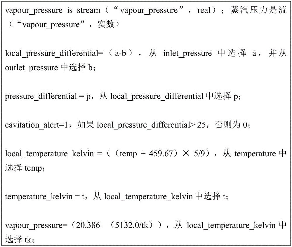
Table a provides examples of physical sensors and SXL sensors created using SXL.
TABLE A


In the above example, four physical sensors are used to create a set of SXL sensors. The SXL sensor data may be sent to local storage or applications, or to other remote services (e.g., the cloud) for further analysis.
As a specific example, there is a virtual sensor named "pressure _ differential" in Table A. Wherein the variable pressure _ differential is output. The inputs to the virtual sensors are the inlet _ pressure and the outlet _ pressure. The virtual sensor outputs a pressure _ differential based on a function inlet _ pressure-output _ pressure.
Table A has another virtual sensor named "temperature _ kelvin". temperature _ kelvin is the output of the function (temperature +459.67) × (5.0/9.0), where temperature is the input to the sensor.
Table a has another virtual sensor named "vapor _ pressure". The output vapor _ pressure is the output of the function exp (20.386- (5132.0/temperature _ kelvin), where temperature _ kelvin is the input to the sensor.
Table B provides an example of defining virtual sensors using the Vel expression language of FogHorn.
TABLE B

In the above example, three physical sensor data streams are used to create a set of virtual sensors that are later used to detect a pump cavitation scenario. The virtual sensor may be a local stream or may be distributed as a first type of data stream on the data bus.
FIG. 7 shows a sensor expression language engine 707 for creating virtual sensors from input. The sensor expression language engine obtains input from physical sensors or other virtual sensors. Some examples of inputs include inlet pressure 711, outlet pressure 714, temperature 717, and flow 720. Any number or combination of inputs may be used as inputs to the virtual sensor. Based on the inputs, the sensor expression language engine may generate virtual sensors with outputs, such as pressure difference 731, temperature 734 (which may be in kelvin units), and steam pressure 737. There may be any number of virtual sensors and outputs. As described above, the output may be a mathematical function of the inputs to the virtual sensor.
Although fig. 7 shows blocks (e.g., 731, 734, and 737) representing virtual sensors. The virtual sensor may have multiple outputs. For example, virtual sensors 731 and 734 may be combined into a single virtual sensor having two outputs. Virtual sensors 731, 734, and 737 may be combined into a single virtual sensor having three outputs.
Application mobility between edges and clouds
Traditional enterprise software application hosting relies on a data center or "cloud" infrastructure to exploit economies of scale and system efficiency. However, these data centers may be located any distance from the physical operating points (e.g., factories, warehouses, retail stores, and other facilities) at which the enterprise performs most of the job operations. Internet of things (IoT) refers to a set of use cases that rely on physically operating instruments that utilize sensors that track events at very high frequencies.
The system includes a method and apparatus for seamless interoperability and mobility of software applications between a back-end data center or cloud and a front-line edge infrastructure layer:
1. the apparatus is a software platform that can be deployed in different forms across clouds, mid-scale computing servers, and small scale computing servers with the same set of Application Program Interfaces (APIs) that can be used by applications to accomplish data management, data analysis, and management tasks while performing physical jobs.
1.1. Data management includes ingesting data streams from multiple network interfaces at the edge layer, data enrichment, storage, toughness against hardware and software failures, and data consistency.
1.2. Data analytics include Complex Event Processing (CEP) engines, expression languages for analytics or stream processing, or for analytics and processing, collections, rules, and selection of machine learning workflows at the edges.
1.3. Management functions include resource deployment, configuration and setup at the edge layer and application lifecycle task management.
2. The system also includes a method for migrating these applications between the cloud and edge infrastructure layers over the internet while maintaining consistency of the state of the managed applications and data.
3. The method utilizes application container technology to package software libraries needed for consistent migration or execution across different platforms.
4. The method may also have a recommender system that schedules such migration between the cloud and the edge layers of the infrastructure taking into account resource availability, application quality of service (QoS) requirements, and priorities.
5. The method also allows applications to collaborate to execute on both the cloud and edge layers of the infrastructure and to manage communication between applications using the device (e.g., edge platform).
Applications developed at the edge may run in the cloud and vice versa. The same is true for machine learning applications.
Remote management workflow
Part of the above system as part of the edge computing software can be remotely managed through a management console supported by several microservices. A plurality of different edge installations can be configured, deployed, managed and monitored through this remote management console.
A method for implementing intelligence at an edge. The method is characterized by comprising the following steps: triggered by sensor data in a software layer hosted on the gateway device or embedded system. The software layer is connected to a local area network. A repository of services, applications and data processing engines is enabled to be accessed by the software layer. The sensor data is matched with a semantic description of the occurrence of a particular condition by an expression language provided by the software layer. Pattern events are automatically discovered by continuously executing expressions. Services and applications are intelligently orchestrated across gateway devices and embedded systems on the network managed by the software layer to link applications and analyze expressions. The layout of the application and analysis is optimized based on resource availability. The health of the software layer is monitored. Storing the raw sensor data or the results of the expression in a local time series database or cloud storage. Services and components may be containerized to ensure smooth operation in any gateway environment.
In an embodiment, a method for service invocation, wherein a service invocation is triggered by sensor data in a software appliance hosted on a gateway device and connected to a wide area network, wherein a repository of services, applications and data processing engines is enabled to be accessed by the appliance; matching the sensor data with a semantic description of data that may be provided by the device; finding all applications designed for patterns of matching data semantic types; intelligently orchestrating services across gateway devices and servers distributed across a wide area network managed by a software device to link all matching applications and analytics; the layout of the application and analysis is optimized based on resource availability at the gateway device.
1. The technical field is as follows: the present invention relates to the field of internet of things, and in particular to distributed software for deriving real-time data-driven decisions from sensors.
2. Discussion: sensor data sets have grown explosively due to the reduction in cost of sensors and networks (collectively, the internet of things). The abstraction of data outlines the internet of things across various vertical industries, including manufacturing, energy and utilities, city infrastructure, healthcare, retail, agriculture and resources, home automation, and consumer wearable devices. However, the dramatic increase in the cost of software development, testing, deployment, and management in turn increases the economic hurdle of ingesting, aggregating, managing, and processing these sensor data for the purpose of creating value in terms of process efficiency, business profitability, and revenue monetization. These economic barriers to internet of things software can be classified into four categories:
1. heterogeneity: data sources in the physical world are heterogeneous in nature, and the accumulation of heterogeneous data sources can increase the cost burden of software development and testing.
2. Last mile breach: there is a gap between data centers and physical sensors for reliably deploying software applications with high quality of service.
3. Safety: sensors are new sources of data that characterize new information paths with less defined data governance and security policies.
4. Storage silo (silo): the collection, processing, and management of duplicate data across application repositories can make the use of hardware and development resources inefficient.
The system provides a method and software means designed to address these last mile challenges near the sensors. The intelligence in the device can find the semantics of the sensor data; customizing orchestration of services and analytics, and linking deployment of software applications.
Some embodiments of the present invention include a method and apparatus for enabling a software application to access data from various sensors throughout a wide area and provide real-time responses and messages based on the data and analysis. The apparatus is designed to be deployed on an embedded gateway device in proximity to sensors and server infrastructure in a data center managed by an enterprise or cloud service provider. Application developers express to the device the data semantics used by their software and expose their application repository to the device. The gateway device may access the physical sensors through a network interface in its hardware system.
The claimed method solves the heterogeneity, last mile breach, security, and data storage bin challenges of the internet of things software as follows:
1.1. the sensor data reaches the software means through a network interface in the gateway device. The software means checks the message header indicating the mode of the known data protocol supported.
1.2. Once the pattern of supported protocols is found, the device loads the relevant protocol-signing services in the first phase of orchestration.
2. The software device discovers the dimensions of the data semantics in the data stream through the agreement theory, matches patterns in the semantics expressed by the application developer, and creates a scored list of matched elements. All matching scans are protected by token exchange protocol to ensure that developers have access to the data being matched. The device may load the data semantics with the highest match score or recommend the same data semantics for human validation through a human-machine interface. The service orchestration adds developer data semantics.
3. The software device then blends the sensor data from the different physical sources to match the data semantic definition of the application.
4. The analytical service dependencies of the applications are analyzed and provisioned by software devices on the gateway devices in the vicinity of the sensors and other servers in the data center under the management of the same devices.
5. A data stream with appropriate semantics is passed through a data processing pipeline by a software device to convert the data according to the application needs.
6. The apparatus also manages data transmission over the wide area network over the secure link to achieve consistency between the geographically dispersed analysis processing pipelines.
7. The application can securely access the converted data through a programming API (with token exchange based security) that is exposed to the developer in the software device manual. Depending on the quality of service requirements and resource availability at the instance, the application is linked to the service portfolio at the appropriate site (gateway device, data center server).
Stages 1-7 above describe a method for intelligently orchestrating a service chain by a software device by exploiting the dynamic environment from sensor data and applications in a repository. Therefore, the method and the software device solve the problem of the Internet of things in software engineering.
Heterogeneous sensor agnostic software and data management
The internet of things (IoT) brings value to business operations through physical work facilities equipped with high-sensitivity sensors, where events in operation are tracked at high frequency and sensor data is translated into operational analytics profiling through software and services. However, the physical facilities of everyday operations (e.g., factories, warehouses, retail stores, and other facilities) are significantly heterogeneous in terms of sensor hardware, network topology, data protocols, and data formats. This heterogeneity can cause high cost overhead in software development, testing, and deployment; the code modules need to be re-developed for each combination of hardware networking data protocol data formats. The system provides a method and software means for managing software and data in such a heterogeneous set-up environment.
The software devices are optionally designed to be hosted on computing infrastructure that includes, for example, a midrange server (e.g., dual-core processor and 4 gigabytes of memory) collocated in a sensor network to a miniaturized server (e.g., single-core processor core with less than 1 gigabyte of memory). The methods described below abstract heterogeneity in sensor networks through a digital interface layer between the sensors and applications hosted on software devices:
1. signature (e.g., signature 520 of fig. 5): when a sensor is connected, a connection session occurs, and then the corresponding client will publish and subscribe to the topic name. This is a multi-protocol signature that is optimized for the purpose of reading large amounts of data. The signature has established a security mechanism to protect access to the security credentials. The signature has a profile containing the login name and password of the particular user. The deployment also establishes policies regarding access to the subject. The system is a general-purpose system sufficient to apply these features to built-in and seed protocol deployments such as MQTT, CoAP, AMQP, or DNP3, as well as custom protocols. The plug-in architecture for protocol deployment makes the development of the deployment for custom protocols very easy. The signature itself has high performance and uses zero-copy buffering to achieve fast processing. The signature layer is a lightweight high-availability implementation that can avoid any single point of failure. It has a Directed Acyclic Graph (DAG) based on dynamic computing Domain Specific Language (DSL), thus making the signature layer flexible and intuitive. Messages may not arrive in timestamp order and it is therefore difficult to know when to close the time window for computation. Signature a model to overcome this problem can be implemented by tracking the low bit level (low watermark) of the application clock.
2. Flow processing diagram: the system uses a Directed Acyclic Graph (DAG), which is a "stream processing graph," to describe producer-consumer relationships between processing units associated with a stream. There are source nodes, sink nodes, and processing nodes in the graph, where directed edges represent the flow of information between the nodes. The source node corresponds to a source of the input data stream. These nodes have only outgoing edges and they do not have any edges between each other. The sink node corresponds to the recipient of the final processed information. These nodes only have edges flowing to them and they do not have any edges between each other. A processing node represents a processing unit. A processing unit may need to input from multiple data streams simultaneously and produce one or more valuable output streams. Such a graph may be drawn in such a way that all directed edges point downward. The system is designed such that the information comes from the top and is ultimately directed to the output stream at the bottom through the intermediate processing units.
3. The queue system: the relationship between delay and throughput between different tiers is very complex, as defined by the litter law. Each system is considered as a whole, and each system comprises a plurality of subsystems, and complex dependency relationships exist among the subsystems. Each subsystem is tied to the rest of the system by throughput or latency. In designing a system, it is useful to take these interactions into account and create a system that does not hinder a larger system. Problems with flow control can arise in asynchronous communications if a sensor sends a message at a higher rate than a receiver (one of them) can process the message.
The developed system has completed many experiments dealing with backpressure problems in high capacity asynchronous systems and has subsequently created a powerful reactive flow processing and queuing mechanism. The main driving force behind the initiation of these autonomously initiated reactive flows is the lossless transfer of data across asynchronous boundaries in memory without the need for an unrestricted buffer. A continuation passing style (e.g., participant mode) is used. When the demand on the stream downstream is zero, the participants do not get more streams from their own upstream and, because the participants are message driven, they are scheduled only when there is more demand on the stream downstream. For this reason, neither thread is blocked nor the call stack is saved, but the participant remembers where it was in the flow. This design has prompted the implementation of a new way to take into account non-determinism in message processing.
4. An edge mixer: each sensor publishes its own theme. The time interval at which the measurements are announced is related to the sensor. Finally, standardization is required to mix the sensors. Sensor measurements are distributed to a time-based channel. These measurements are issued in a round-robin fashion to the queues. Some or all of the sensor measurements may be stitched together in the time dimension. The sensor mixer of the system performs one or more of the following sensor time series normalization:
4.1. normalized to within the interval.
4.2. Normalized to the sum 1.
4.3. Normalized to euclidean norm 1.
4.4. Normalized to zero mean.
4.5. Normalized to zero mean and unit standard deviation.
5. Sensor expression language: the application defines the pipeline workflow in the edge mixer by a language called sensor expression language. The language defines application-side abstractions for data management and analysis, thereby controlling the end-to-end approach to abstract sensor heterogeneity. A specific embodiment of the sensor expression language is known as vel (r) and is described in U.S. patent applications 62/312,106, 62/312,187, 62/312,223, and 62,312,255 filed 3-23-2016, the contents of which are incorporated herein by reference. Vel is a trademark of FogHorn Systems, inc.
Intelligent container creation and management based on edge and device type
The container technique can be negligible overhead to virtualize computer server resources (e.g., memory, CPU, and storage) as a managed Operating System (OS) without copying the entire OS kernel for each tenant (and thus unlike the hypervisor technique). Containers were developed as part of the current Linux open source operating system and with the popularity of advanced management frameworks such as Docker and CoreOS have had tremendous appeal in relation to software development and data center operations ("DevOps"). There is an increasing demand for software and analysis performed for processing sensor data on a near-line computing infrastructure in close proximity to a physical sensor network in internet of things (IoT) use cases, including physical locations in factories, warehouses, retail stores, and other facilities. These computing nodes include, for example, servers ranging from medium servers (e.g., dual-core processors and 4 gigabytes of memory) to small servers (e.g., single-core processor cores with less than 1 gigabyte of memory), which are connected to the internet and can access the various heterogeneous sensor devices and control systems deployed at job time. The system provides a method to intelligently deploy and manage container technology in these edge computing infrastructure settings.
The following constituent elements describe a method for managing containers in an edge infrastructure environment and are implemented in the form of software means:
1. centralized control: the system manages software applications in its industry AppStore for IoT (TM), and all deployment decisions are controlled and managed in this centralized setting. AppStore for IoT is a trademark of FogHorn Systems, Inc.
2. Deploying a topological template: the system has a template for each software application module that is self-contained with all the topology details and runtime libraries needed for deployment on the edge infrastructure. Deployment includes orchestrating the required network protocols, message protocols, and data format parser libraries into a chain of services that applications can use to access data from systems in the sensor network. Service orchestration is performed in an intelligent and automatic manner using system configuration information in the target edge infrastructure.
3. Mobility of application containers: the system serializes the deployment template objects containing the configured applications and streams them over the internet to agents in the software devices at the edge infrastructure.
4. Zero contact deployment at the edge: the system software devices at the edge can parse the configured container objects received from the industrial AppStore for iot and deploy them through all analytics and data management services implemented in the platform. While some manual operations may be required in the configuration, the deployment process is fully automated, requiring no manual intervention.
5. Monitoring of application containers: the system deploys a microservice-based architecture in a software platform (device) at the edge that implements the telemetry agent in each container. Such agents would measure and report detailed metrics on the performance and availability of applications in the container. The platform can also issue an alert if any of these metrics perform abnormally.
6. Response migration of the container: in the event that the telemetry agent observes resource contention and service degradation, the system provides a method that triggers migration of the container from the edge platform back to the cloud. Such responsive migration frees resources in the restricted edge infrastructure and hopefully improves the overall quality of service of the hosted application. The priority of the application also serves as a guide criterion for scheduling such migration.
Method for automated model-parallel machine learning for very large sensor networks and device for data parallel transfer learning between sensor networks and data centers
Machine learning has evolved into a key computational construct for automatically discovering patterns in data and using the constructed models for intelligent prediction in various industrial fields. The application of machine learning on sensor data is relevant to data driven traffic and operational planning use cases throughout the internet of things (IoT) chunking market. However, the scalability and efficiency of sensor data to machine learning workflows presents several challenges:
1. amount of stream data: control systems and machines deployed in a job produce an extremely large amount of continuous streaming data, which imposes cost and logistical constraints on the assembly for machine learning analysis.
2. Data quality and complexity: data from industrial systems has a very small amount of structural and metadata associated with overwhelming data corruption and missing values. These characteristics that make up the generated data appear to vary widely between different instances of similar operating systems. This severely degrades the fidelity of the model developed by traditional machine learning analysis.
3. Gap in data preprocessing: there is a lack of computing infrastructure to preprocess data closer to the source in an intelligent and efficient manner.
4. Geographic distribution: industrial jobs in IoT scenarios involve systems deployed in large geographic areas, which imposes cost, bandwidth, and delay constraints on the distribution of any computation and data.
The system provides a software device in the form of a platform designed to execute machine learning workflows across a data center or "cloud" and compute resources available near the sensor network or "edge," such as resources from a midrange server (e.g., dual-core processors and 4 gigabytes of memory) to a miniaturised server (e.g., single-core processor cores with less than 1 gigabyte of memory). The method of the system may comprise the steps of:
1. streaming data processing at the edge and in-network aggregation to pre-process a continuous raw data stream that can be fed to machine learning analysis — the processing method can be programmed through an API by the developer building the machine learning analysis.
2. Sensor data query processing for a model built by a machine learning workflow to execute on the preprocessed data at the edge and send the execution results to the cloud for model evaluation.
3. Sensor data segmentation is performed at the edges for partitioning raw data based on their constituent feature sets and for intelligent matching with models established by machine learning workflows.
4. Based on the above-described pre-processing, query-based model execution, and feature-based data segmentation workflows, real-time model training and selection is performed in an edge software platform.
The method comprising these three steps enables the construction of a machine-learned system as a service. A specific implementation from the FogHorn systems is known as FogHorn Cortex.
1. The software devices of the system coordinate execution of the model across instances of the edge infrastructure (across a wide geographic area). These models are executed on data that spans different feature space segments. The apparatus transmits learned knowledge across a feature space by using a cloud as a platform for transfer learning. This provides greater efficiency to the machine learning process by avoiding data tags and utilizing data with heterogeneous tags.
One use case of edge computing platform systems is plant yield optimization. For example, a modern manufacturing facility may wish to maximize production by discovering possible defects as early as possible to correct them before the irreversible stage in the assembly line. Some of the benefits of using an edge computing platform system include: using a combination of FogHorn's real-time data processing, VEL expression engine, and integration with Apache Hadoop for big data analysis, manufacturers may expect a reduction in scrap rate of at least 50%.
Some solutions include:
1. hundreds of MQTT and OPC-UA data values from the device controller and RFID data for each component are collected and converted in real time at the edge.
2. The measurement results were normalized and compiled using the VEL expression and compared to specification.
3. The raw and enhanced data are transmitted to Hadoop, where a datalogist can build a model characterizing the sequence of measurements, which can be used for defect detection.
4. The VEL expression is used to send alerts to technicians to reject or rework a product before irreversible steps (e.g., heating, drying, and painting).
Real-time analysis and intelligence includes: the measurement results and the identifier or ID are collected and converted. The measurements were calculated and pooled using VEL. The history analysis comprises the following steps: predictive features are identified. A sequence mining model for the waste was constructed and tested.
One example of an edge computing platform system is locomotive fuel efficiency. For example, transportation companies need a customizable solution to actively monitor and optimize train and unit performance to reduce fuel consumption. Some of the benefits of using an edge computing platform system include: thousands of gallons of fuel can be saved per engine by detecting excessive idle and inefficient throttle positions based on real-time engine and geographic location data. And the video uploading is triggered only under the abnormal condition, so that the mobile network cost is reduced.
Some solutions include:
1. sensor and GPS data are ingested from the onboard hardened data collection system.
2. The VEL expression is used to determine conditions in idle and throttle adjustments based on position, speed, time, and other parameters.
3. An alert is sent to the command center where the operator can take proactive action to reduce fuel consumption while maintaining optimal train operation.
4. Real-time applications are used to detect unsafe conditions and trigger video streaming uploads to the data center for analysis.
Real-time analysis and intelligence includes: and (6) data collection. Rules and alarms. Triggering data transmission. The history analysis comprises the following steps: rules and predictive models for train operation, safety and fuel consumption.
One use case of an edge computing platform system is a pump cavitation alarm. For example, equipment manufacturers need a solution to detect cavitation events that may result in damage to the pump and control valve products installed in factories and power plants. Some of the benefits of using an edge computing platform system include: corrective action is taken to increase the service life of the equipment when cavitation occurs. Unexpected outages and catastrophic failures are avoided through predictive maintenance.
Some solutions include:
1. measurements such as inlet and outlet gas pressure, flow and temperature are collected from a plurality of sensors attached to the device.
2. The VEL expression is used to calculate the vapor difference in real time to detect cavitation formation.
3. Alerts are sent to technicians to increase fluid pressure or flow, or to reduce temperature to avoid damage to seals, bearings and impellers.
4. The historical information is analyzed to identify patterns to enable a technician to detect cavitation or schedule maintenance before a fault occurs.
Real-time analysis and intelligence includes: the measurement results are collected and converted in real time. The difference in vapor leading to cavitation was calculated using the VEL. The history analysis comprises the following steps: the time series measurements are analyzed to identify a pattern of cavitation events.
One use case of edge computing platform systems is wind energy forecasting. For example, renewable energy companies need to accurately predict, report, and meet power generation needs within 24 hours of the future, as required by governments. Some of the benefits of using an edge computing platform system include: alerts can be generated at least 90 minutes ahead of time before the turbine fails to meet the 24 hour energy generation forecast and applied to optimize turbine settings or modify the forecast.
Some solutions include:
1. historical and real-time data is collected over a six month or longer period from the SCADA controller system for each turbine and weather, atmospheric and terrain data is augmented.
2. The model is trained based on 20 or more attributes to predict power generation over a 15 minute time period.
3. The model is applied at the edges to generate a real-time score of the power generation. The VEL expression is used to compare the performance to the prediction to generate an alert.
4. Enabling the technician to fine tune the turbine settings or modify the predictions.
Real-time analysis and intelligence includes: data is collected and converted. Scoring and updating the model. The condition is identified with the VEL. The history analysis comprises the following steps: and (5) carrying out statistical analysis. And (5) extracting features. And constructing and testing the model.
The description of the present invention has been presented for purposes of illustration and description. It is not intended to be exhaustive or to limit the invention to the precise form described, and many modifications and variations are possible in light of the above teaching. The embodiments were chosen and described in order to best explain the principles of the invention and its practical applications. This description enables others skilled in the art to best utilize and practice the invention in various embodiments with various modifications as are suited to the particular use contemplated. The scope of the invention is defined by the appended claims.
Claims (29)
1. A method for improving processing of sensor flow data in a distributed network comprising a local network having a plurality of network devices and a plurality of physical sensors and a remote network, the method comprising:
receiving sensor stream data from a first physical sensor over a first network connection type at a data ingestion agent of an edge platform system;
communicating the ingested sensor stream data from the data ingest agent to a data bus of the edge platform system;
enriching ingested sensor stream data in real-time via a data enrichment component of the edge platform system by performing enrichment operations on the ingested sensor stream data, wherein the enrichment operations include one or more of: decoding the ingested sensor stream data, supplementing the ingested sensor stream data with metadata, and normalizing the ingested sensor stream data;
enabling the enriched ingested sensor stream data to be available on the data bus;
processing the enriched ingested sensor stream data at an analytics engine of the edge platform system that subscribes to data from the data bus, wherein the processing comprises applying in real-time to the enriched ingested stream data a first function specified by the selected analytical expression expressed in the expression language and generating in real-time a data stream comprising intelligent information, wherein the first function comprises at least one of: transformation, mode detection, dynamic calibration, signal processing, mathematical expression, data compression, data analysis, data aggregation, rule application, alarm and service invocation;
publishing the intelligent information on the data bus, wherein the publishing includes storing the intelligent information on the edge platform system in a rolling time-series database indexed by time for use by an application executable on the edge platform system; and
determining, based on the intelligence information, whether to perform a selected operation in a local network on a hardware device monitored by the first physical sensor and whether to send at least a portion of the intelligence information to a remote network for further processing, wherein the selected operation comprises: sending an alert to an operator or performing a corrective action on a hardware device monitored by the first physical sensor.
2. The method of claim 1, comprising:
transmitting and storing at least a portion of the intelligent information to the remote network through a second network connection type in a cloud storage connected to the remote network.
3. The method of claim 2, wherein the second network connection type is different from the first network connection type, and the second network connection type has a lower bandwidth connection to the sensor flow data than the first network connection type.
4. The method of claim 2, wherein receiving over the first network connection type comprises receiving according to at least one of MQTT, OPC unified architecture, or Modbus protocol.
5. The method of claim 4, wherein transmitting over the second network connection type comprises transmitting according to at least one of TCP/IP, Hypertext transfer protocol (HTTP), WebSockets, WebHDFS, Apache Kafka, or an Internet protocol.
6. The method of claim 1, wherein the data ingestion agent accesses the sensor stream data via a push protocol over a first network connection type.
7. The method of claim 1, wherein the data ingestion agent accesses the sensor stream data via a pull protocol over a first network connection type.
8. The method of claim 1, comprising:
providing a software development kit that allows a user to develop applications for the edge platform system; and
developing, by the software development kit, a first containerized application capable of accessing and processing the intelligence information available from the data bus.
9. The method of claim 8, comprising:
developing, by the software development kit, a second containerized application capable of accessing and processing the intelligence information stored in the time series database.
10. The method of claim 9, comprising:
providing an application store of the edge platform system, wherein the first containerized application and the second containerized application are accessible to other users through the application store.
11. The method of claim 1, wherein the processing enriched ingested sensor flow data comprises:
creating a first virtual sensor using the expression language, the first virtual sensor having a first input and a first output, wherein the first input is coupled to the output of the first physical sensor,
the first virtual sensor receives first sensor flow data from the first physical sensor at the first input and outputs second sensor flow data that is a result of operating on the first sensor flow data according to the first function at the first output.
12. The method of claim 1, comprising:
creating a first virtual sensor using the expression language, the first virtual sensor having a first input, a second input, and a first output, wherein the first input is coupled to the output of the first physical sensor, the second input is coupled to the output of a second physical sensor,
the first virtual sensor receives first sensor flow data from the first physical sensor and second sensor flow data from the second physical sensor, and at the first output, the first virtual sensor outputs third sensor flow data that is a result of operating on the first sensor flow data and the second sensor flow data according to the first function.
13. A method for improving processing of sensor data in a distributed network comprising a local network having a plurality of physical devices and a plurality of physical sensors and a remote network, the method comprising:
receiving, at a data ingestion agent of an edge platform system connected to the local network between the first physical sensor and the remote network, first sensor flow data from a first physical sensor in the local network over a first network connection type;
transmitting the ingested first sensor flow data from the data ingest agent to a data bus of the edge platform system;
enriching, by a data enrichment component of the edge platform system, the ingested first sensor stream data in real-time and enabling the enriched ingested first sensor stream data to be available on the data bus, wherein the enriching comprises one or more of: decoding the ingested sensor stream data, supplementing the ingested sensor stream data with metadata, and normalizing the ingested sensor stream data;
processing the enriched ingested first sensor stream data in real-time at an analytics engine of the edge platform system that subscribes to data from the data bus without first sending the first sensor stream data to the remote network, wherein the processing comprises executing an analytical expression provided in an expression language to generate intelligent information from the enriched ingested first sensor stream data, wherein the analytical expression comprises at least one of: transformation, pattern detection, dynamic calibration, signal processing, mathematical expression, data compression, data analysis, data aggregation, rule application, alarm, and service invocation;
making the intelligence information available on the data bus; and
determining, based on the smart information, whether to send at least a portion of the smart information to the remote network for further processing, and whether to perform a selected operation in the local network for an operation in the local network monitored by the first physical sensor without waiting for further processing of the smart information at the remote network, wherein the selected operation comprises at least one of: generating an alert and changing operations in the local network.
14. The method of claim 13, comprising:
storing the intelligent information on the edge platform system in a rolling time series database indexed by time for use by an application executable on the edge platform system.
15. The method of claim 14, comprising:
providing a software development kit that allows a user to develop applications executable on the edge platform system; and
developing, by the software development kit, a first containerized application capable of accessing and processing the intelligence information available from the data bus.
16. The method of claim 15, comprising:
developing, by the software development kit, a second containerized application capable of accessing and processing the intelligence information stored in the time series database.
17. The method of claim 16, comprising:
providing an application store of the edge platform system, wherein the first containerized application and the second containerized application are accessible to a user through the application store.
18. The method of claim 13, wherein determining whether to send at least a portion of the intelligent information to the remote network for further processing comprises determining whether to aggregate the intelligent information with other information prior to sending to the remote network.
19. The method of claim 13, wherein processing the enriched ingested first sensor flow data comprises:
creating a first virtual sensor using the expression language, the first virtual sensor having a first input and a first output, wherein the first input is coupled to the output of the first physical sensor,
the first virtual sensor receives first sensor flow data from the first physical sensor at the first input and outputs second sensor flow data operated on the first sensor flow data according to the analytical expression at the first output.
20. A method for improving processing of sensor data in a distributed network, the distributed network including a local network and a remote network, the local network having a plurality of physical devices and a plurality of physical sensors that each generate sensor flow data about a subject, the method comprising:
receiving, at a data ingestion agent of an edge platform system connected to the local network between the first physical sensor and the remote network, first sensor flow data from a first physical sensor in the local network over a first network connection type;
transmitting the ingested first sensor flow data from the data ingest agent to a data bus of the edge platform system;
enriching, by a data enrichment component of the edge platform system, the ingested first sensor stream data in real-time and enabling the enriched ingested first sensor stream data and information identifying a subject matter of the first sensor stream data to be available on the data bus, wherein the enriching comprises one or more of: decoding the ingested sensor stream data, supplementing the ingested sensor stream data with metadata, and normalizing the ingested sensor stream data;
storing, on the edge platform system, a plurality of sets of analytical expressions provided in an expression language, wherein each set of analytical expressions defines a function that can be performed on the enriched ingested first sensor flow data from the data bus and includes at least one of: transformation, pattern detection, dynamic calibration, signal processing, mathematical expression, data compression, data analysis, data aggregation, rule application, alarm, and service invocation;
processing the enriched ingested first sensor flow data in real-time at an analytics engine of the edge platform system that subscribes to data from the data bus without first sending the first sensor flow data to the remote network, wherein the processing comprises: automatically selecting a first set of analytical expressions defining a first function from the plurality of sets of analytical expressions based on a topic of the first sensor flow data and executing the selected set of analytical expressions to generate intelligent information from the enriched ingested first sensor flow data;
making the intelligence information available on the data bus; and
determining, based on the smart information, whether to send at least a portion of the smart information to the remote network for further processing, and whether to perform selected operations in the local network for operations in the local network monitored by the first physical sensor and involving a network device without waiting for further processing of the smart information at the remote network, wherein the selected operations comprise at least one of: generating an alert and changing operations in the local network.
21. The method of claim 20, comprising:
storing the intelligent information on the edge platform system in a rolling time series database indexed by time for use by an application executable on the edge platform system.
22. The method of claim 21, comprising:
providing a software development kit that allows a user to develop applications executable on the edge platform system; and
developing, by the software development kit, a first containerized application capable of accessing and processing the intelligence information available from the data bus.
23. The method of claim 22, comprising:
developing, by the software development kit, a second containerized application capable of accessing and processing the intelligence information stored in the time series database.
24. The method of claim 23, comprising:
providing an application store of the edge platform system, wherein the first containerized application and the second containerized application are accessible to a user through the application store.
25. The method of claim 20, wherein determining whether to send at least a portion of the intelligent information to the remote network for further processing comprises determining whether to aggregate the intelligent information with other information prior to sending to the remote network.
26. The method of claim 20, wherein processing the enriched ingested first sensor flow data comprises:
creating a first virtual sensor using the expression language, the first virtual sensor having a first input and a first output, wherein the first input is coupled to the output of the first physical sensor,
the first virtual sensor receives first sensor flow data from the first physical sensor at the first input and outputs second sensor flow data that is a result of operating on the first sensor flow data according to the first function at the first output.
27. A method for improving processing of sensor flow data in a distributed network comprising a local network having a plurality of network devices and a plurality of physical sensors and a remote network, the method comprising:
receiving, at a data ingestion agent of an edge platform system, first streaming data from a first physical sensor over a first network connection type;
communicating the ingested first stream data from the data ingest agent to a data bus of the edge platform system;
enriching the ingested data in real-time and making the ingested data available on the data bus by a data enrichment component of the edge platform system, wherein the enrichment operation comprises one or more of the following operations: decoding the ingested stream data, supplementing the ingested stream data with metadata, and normalizing the ingested stream data;
providing an analysis engine of the edge platform system, the analysis engine coupled to the data bus, wherein the analysis engine processes code provided in an expression language;
creating a first virtual sensor using the expression language, the first virtual sensor having a first input and a first output, wherein the first input is coupled to an output of the first physical sensor and the first output is a first function of the first input, and the first function is specified in the expression language,
a first input of the first virtual sensor receives the first stream data from the first physical sensor, and a first output of the first virtual sensor outputs second stream data comprising the first stream data after operating according to the first function, and the first function comprises at least one of: transformation, pattern detection, dynamic calibration, signal processing, mathematical expression, data compression, data analysis, data aggregation, rule application, alerts and service invocation, and
the second streaming data is made available on the data bus without experiencing the data-rich component and without being enriched by the data-rich component;
processing, at the analytics engine that subscribes to data from the data bus, ingested streaming data of the first streaming data from the first physical sensor and the second streaming data of the first virtual sensor, wherein the processing comprises executing an analytical expression provided in the expression language to generate intelligent information from the ingested streaming data and second streaming data; and is
Publishing intelligent information on the data bus originating from the ingested streaming data of the first physical sensor and the second streaming data of the first virtual sensor.
28. The method of claim 27, comprising:
building at least one model for intelligent pattern matching of streaming data through machine learning; and
segmenting the first stream data using a model for intelligent pattern matching, wherein the segmented first stream data is used for a first input of the first virtual sensor.
29. The method of claim 27, comprising:
storing the second stream data of the first virtual sensor in a time series database;
analyzing the second stream data stored in the time series database to match one or more patterns in the data;
identifying a first pattern match in second stream data stored in the time series database; and is
Altering operation of a first hardware device being monitored by the first physical sensor based on the identified first pattern match in second stream data stored in the time series database.
Priority Applications (1)
| Application Number | Priority Date | Filing Date | Title |
|---|---|---|---|
| CN202010156229.XA CN111367187B (en) | 2015-08-27 | 2016-08-29 | Method for improving the processing of sensor flow data in a distributed network |
Applications Claiming Priority (3)
| Application Number | Priority Date | Filing Date | Title |
|---|---|---|---|
| US201562210981P | 2015-08-27 | 2015-08-27 | |
| US62/210,981 | 2015-08-27 | ||
| PCT/US2016/049316 WO2017035536A1 (en) | 2015-08-27 | 2016-08-29 | Edge intelligence platform, and internet of things sensor streams system |
Related Child Applications (1)
| Application Number | Title | Priority Date | Filing Date |
|---|---|---|---|
| CN202010156229.XA Division CN111367187B (en) | 2015-08-27 | 2016-08-29 | Method for improving the processing of sensor flow data in a distributed network |
Publications (2)
| Publication Number | Publication Date |
|---|---|
| CN108353090A CN108353090A (en) | 2018-07-31 |
| CN108353090B true CN108353090B (en) | 2020-04-03 |
Family
ID=58100985
Family Applications (2)
| Application Number | Title | Priority Date | Filing Date |
|---|---|---|---|
| CN201680050011.8A Active CN108353090B (en) | 2015-08-27 | 2016-08-29 | Method for improving processing of sensor streaming data in a distributed network |
| CN202010156229.XA Active CN111367187B (en) | 2015-08-27 | 2016-08-29 | Method for improving the processing of sensor flow data in a distributed network |
Family Applications After (1)
| Application Number | Title | Priority Date | Filing Date |
|---|---|---|---|
| CN202010156229.XA Active CN111367187B (en) | 2015-08-27 | 2016-08-29 | Method for improving the processing of sensor flow data in a distributed network |
Country Status (9)
| Country | Link |
|---|---|
| US (4) | US10379842B2 (en) |
| EP (1) | EP3342137B1 (en) |
| JP (1) | JP6925321B2 (en) |
| KR (1) | KR102471665B1 (en) |
| CN (2) | CN108353090B (en) |
| AU (1) | AU2016310529B2 (en) |
| ES (1) | ES2886868T3 (en) |
| SA (1) | SA518391000B1 (en) |
| WO (1) | WO2017035536A1 (en) |
Families Citing this family (402)
| Publication number | Priority date | Publication date | Assignee | Title |
|---|---|---|---|---|
| US9411327B2 (en) | 2012-08-27 | 2016-08-09 | Johnson Controls Technology Company | Systems and methods for classifying data in building automation systems |
| US10824618B2 (en) | 2015-09-09 | 2020-11-03 | Intel Corporation | Separated application security management |
| US10534326B2 (en) | 2015-10-21 | 2020-01-14 | Johnson Controls Technology Company | Building automation system with integrated building information model |
| US10072951B2 (en) * | 2015-12-04 | 2018-09-11 | International Business Machines Corporation | Sensor data segmentation and virtualization |
| US11947785B2 (en) | 2016-01-22 | 2024-04-02 | Johnson Controls Technology Company | Building system with a building graph |
| US11268732B2 (en) | 2016-01-22 | 2022-03-08 | Johnson Controls Technology Company | Building energy management system with energy analytics |
| US12196437B2 (en) | 2016-01-22 | 2025-01-14 | Tyco Fire & Security Gmbh | Systems and methods for monitoring and controlling an energy plant |
| US10397331B2 (en) * | 2016-01-29 | 2019-08-27 | General Electric Company | Development platform for industrial internet applications |
| US12276420B2 (en) | 2016-02-03 | 2025-04-15 | Strong Force Iot Portfolio 2016, Llc | Industrial internet of things smart heating systems and methods that produce and use hydrogen fuel |
| US11768004B2 (en) | 2016-03-31 | 2023-09-26 | Johnson Controls Tyco IP Holdings LLP | HVAC device registration in a distributed building management system |
| WO2017186260A1 (en) * | 2016-04-25 | 2017-11-02 | Huawei Technologies Co., Ltd. | Edge server and method of operating an edge server |
| US11774920B2 (en) | 2016-05-04 | 2023-10-03 | Johnson Controls Technology Company | Building system with user presentation composition based on building context |
| US10505756B2 (en) | 2017-02-10 | 2019-12-10 | Johnson Controls Technology Company | Building management system with space graphs |
| US10417451B2 (en) | 2017-09-27 | 2019-09-17 | Johnson Controls Technology Company | Building system with smart entity personal identifying information (PII) masking |
| US20210157312A1 (en) * | 2016-05-09 | 2021-05-27 | Strong Force Iot Portfolio 2016, Llc | Intelligent vibration digital twin systems and methods for industrial environments |
| US20180007115A1 (en) * | 2016-07-01 | 2018-01-04 | Cisco Technology, Inc. | Fog enabled telemetry embedded in real time multimedia applications |
| US11122112B1 (en) * | 2016-09-23 | 2021-09-14 | Jpmorgan Chase Bank, N.A. | Systems and methods for distributed micro services using private and external networks |
| US10984897B2 (en) | 2016-10-27 | 2021-04-20 | Snaps Solutions, Llc | Systems and methods for surfacing contextually relevant content into the workflow of a third party system via a distributed architecture |
| US11003978B2 (en) | 2016-12-14 | 2021-05-11 | Ajay Khoche | Programmable network node roles in hierarchical communications network |
| US10684033B2 (en) | 2017-01-06 | 2020-06-16 | Johnson Controls Technology Company | HVAC system with automated device pairing |
| US10574736B2 (en) * | 2017-01-09 | 2020-02-25 | International Business Machines Corporation | Local microservice development for remote deployment |
| US11900287B2 (en) | 2017-05-25 | 2024-02-13 | Johnson Controls Tyco IP Holdings LLP | Model predictive maintenance system with budgetary constraints |
| US11764991B2 (en) | 2017-02-10 | 2023-09-19 | Johnson Controls Technology Company | Building management system with identity management |
| US10515098B2 (en) | 2017-02-10 | 2019-12-24 | Johnson Controls Technology Company | Building management smart entity creation and maintenance using time series data |
| US11307538B2 (en) | 2017-02-10 | 2022-04-19 | Johnson Controls Technology Company | Web services platform with cloud-eased feedback control |
| US10417245B2 (en) | 2017-02-10 | 2019-09-17 | Johnson Controls Technology Company | Building management system with eventseries processing |
| US12184444B2 (en) | 2017-02-10 | 2024-12-31 | Johnson Controls Technology Company | Space graph based dynamic control for buildings |
| US11280509B2 (en) | 2017-07-17 | 2022-03-22 | Johnson Controls Technology Company | Systems and methods for agent based building simulation for optimal control |
| US11994833B2 (en) | 2017-02-10 | 2024-05-28 | Johnson Controls Technology Company | Building smart entity system with agent based data ingestion and entity creation using time series data |
| US11360447B2 (en) | 2017-02-10 | 2022-06-14 | Johnson Controls Technology Company | Building smart entity system with agent based communication and control |
| US10452043B2 (en) | 2017-02-10 | 2019-10-22 | Johnson Controls Technology Company | Building management system with nested stream generation |
| US10854194B2 (en) | 2017-02-10 | 2020-12-01 | Johnson Controls Technology Company | Building system with digital twin based data ingestion and processing |
| JP2018147290A (en) * | 2017-03-07 | 2018-09-20 | オムロン株式会社 | Sensor metadata generation apparatus, sensor metadata generation system, sensor metadata generation method, and sensor meta data generation program |
| JP6749281B2 (en) * | 2017-03-23 | 2020-09-02 | エヌ・ティ・ティ・コミュニケーションズ株式会社 | IoT device, signaling server, message bus management server, connection forming method, and program |
| WO2018175912A1 (en) | 2017-03-24 | 2018-09-27 | Johnson Controls Technology Company | Building management system with dynamic channel communication |
| US11327737B2 (en) | 2017-04-21 | 2022-05-10 | Johnson Controls Tyco IP Holdings LLP | Building management system with cloud management of gateway configurations |
| US10788229B2 (en) | 2017-05-10 | 2020-09-29 | Johnson Controls Technology Company | Building management system with a distributed blockchain database |
| EP4421695A3 (en) | 2017-05-25 | 2024-11-27 | Johnson Controls Tyco IP Holdings LLP | Model predictive maintenance system for building equipment |
| US11022947B2 (en) | 2017-06-07 | 2021-06-01 | Johnson Controls Technology Company | Building energy optimization system with economic load demand response (ELDR) optimization and ELDR user interfaces |
| WO2018232147A1 (en) | 2017-06-15 | 2018-12-20 | Johnson Controls Technology Company | Building management system with artificial intelligence for unified agent based control of building subsystems |
| US11823067B2 (en) | 2017-06-27 | 2023-11-21 | Hcl Technologies Limited | System and method for tuning and deploying an analytical model over a target eco-system |
| US11422516B2 (en) | 2017-07-21 | 2022-08-23 | Johnson Controls Tyco IP Holdings LLP | Building management system with dynamic rules with sub-rule reuse and equation driven smart diagnostics |
| MX2020000983A (en) | 2017-07-25 | 2020-07-22 | Weatherford Tech Holdings Llc | Internet of things gateway systems and methods for oil and gas fields. |
| US10619882B2 (en) | 2017-07-27 | 2020-04-14 | Johnson Controls Technology Company | Building management system with scorecard for building energy and equipment performance |
| US11243516B2 (en) * | 2017-07-28 | 2022-02-08 | Siemens Aktiengesellschaft | Edge devices and associated networks utilising microservices |
| CN107454092B (en) * | 2017-08-18 | 2021-09-17 | 北京海兰信数据科技股份有限公司 | OPCUA and DDS protocol signal conversion device, communication system and communication method |
| GB2579739B (en) * | 2017-08-21 | 2022-08-31 | Landmark Graphics Corp | Integrated surveillance and control |
| EP3447645A1 (en) | 2017-08-25 | 2019-02-27 | Siemens Aktiengesellschaft | Smart provisioning software applications on edge devices in an internet-of-things environment |
| US10313413B2 (en) * | 2017-08-28 | 2019-06-04 | Banjo, Inc. | Detecting events from ingested communication signals |
| US20190251138A1 (en) | 2018-02-09 | 2019-08-15 | Banjo, Inc. | Detecting events from features derived from multiple ingested signals |
| US11025693B2 (en) | 2017-08-28 | 2021-06-01 | Banjo, Inc. | Event detection from signal data removing private information |
| US10324948B1 (en) | 2018-04-27 | 2019-06-18 | Banjo, Inc. | Normalizing ingested signals |
| US10581945B2 (en) | 2017-08-28 | 2020-03-03 | Banjo, Inc. | Detecting an event from signal data |
| US10257058B1 (en) | 2018-04-27 | 2019-04-09 | Banjo, Inc. | Ingesting streaming signals |
| JP6691085B2 (en) | 2017-09-20 | 2020-04-28 | ファナック株式会社 | Application security management system and edge server |
| US10600263B2 (en) | 2017-09-27 | 2020-03-24 | Johnson Controls Technology Company | Building management system with identity management and assurance services |
| EP3462705B1 (en) * | 2017-09-27 | 2019-07-10 | Siemens Aktiengesellschaft | Provisioning of software applications on edge devices in an internet-of-things environment |
| WO2019067631A1 (en) * | 2017-09-27 | 2019-04-04 | Johnson Controls Technology Company | Building management system with smart entities, timeseries, nested stream generation, cloud control, and id management and assurance services |
| US11258683B2 (en) | 2017-09-27 | 2022-02-22 | Johnson Controls Tyco IP Holdings LLP | Web services platform with nested stream generation |
| WO2019067630A1 (en) * | 2017-09-27 | 2019-04-04 | Johnson Controls Technology Company | Web services platform with smart entities,timeseries, and nested stream generation |
| US10962945B2 (en) | 2017-09-27 | 2021-03-30 | Johnson Controls Technology Company | Building management system with integration of data into smart entities |
| US20190095821A1 (en) | 2017-09-27 | 2019-03-28 | Johnson Controls Technology Company | Building risk analysis system with expiry time prediction for threats |
| US11120012B2 (en) | 2017-09-27 | 2021-09-14 | Johnson Controls Tyco IP Holdings LLP | Web services platform with integration and interface of smart entities with enterprise applications |
| US11314788B2 (en) | 2017-09-27 | 2022-04-26 | Johnson Controls Tyco IP Holdings LLP | Smart entity management for building management systems |
| US12339825B2 (en) | 2017-09-27 | 2025-06-24 | Tyco Fire & Security Gmbh | Building risk analysis system with risk cards |
| KR102435830B1 (en) * | 2017-09-28 | 2022-08-24 | 한국전자통신연구원 | Method and architecture of Network Infrastructure for Optimal Application Service Processing and Data Sharing among Application domains |
| US11070639B2 (en) * | 2017-09-28 | 2021-07-20 | Electronics And Telecommunications Research Institute | Network infrastructure system and method for data processing and data sharing using the same |
| US10306513B2 (en) | 2017-09-29 | 2019-05-28 | Intel Corporation | Connectivity service level orchestrator and arbitrator in internet of things (IoT) platforms |
| US10924342B2 (en) | 2017-10-24 | 2021-02-16 | Honeywell International Inc. | Systems and methods for adaptive industrial internet of things (IIoT) edge platform |
| US20190132276A1 (en) * | 2017-11-02 | 2019-05-02 | Sap Se | Unified event processing for data/event exchanges with existing systems |
| US10652107B2 (en) * | 2017-11-10 | 2020-05-12 | International Business Machines Corporation | Accessing gateway management console |
| US11689414B2 (en) | 2017-11-10 | 2023-06-27 | International Business Machines Corporation | Accessing gateway management console |
| US10700926B2 (en) | 2017-11-10 | 2020-06-30 | International Business Machines Corporation | Accessing gateway management console |
| US11281169B2 (en) | 2017-11-15 | 2022-03-22 | Johnson Controls Tyco IP Holdings LLP | Building management system with point virtualization for online meters |
| US10809682B2 (en) | 2017-11-15 | 2020-10-20 | Johnson Controls Technology Company | Building management system with optimized processing of building system data |
| US11127235B2 (en) | 2017-11-22 | 2021-09-21 | Johnson Controls Tyco IP Holdings LLP | Building campus with integrated smart environment |
| CN109842636A (en) | 2017-11-24 | 2019-06-04 | 阿里巴巴集团控股有限公司 | Cloud service moving method, device and electronic equipment |
| CN108156225B (en) * | 2017-12-15 | 2021-02-05 | 南瑞集团有限公司 | Micro-application monitoring system and method based on container cloud platform |
| CN109936547A (en) | 2017-12-18 | 2019-06-25 | 阿里巴巴集团控股有限公司 | Identity identifying method, system and calculating equipment |
| RO133453A2 (en) | 2017-12-28 | 2019-06-28 | Siemens Aktiengesellschaft | Motor for processing signals and events |
| WO2019140279A1 (en) | 2018-01-12 | 2019-07-18 | Johnson Controls Technology Company | Building energy optimization system with battery powered vehicle cost optimization |
| US11443230B2 (en) | 2018-01-26 | 2022-09-13 | Cisco Technology, Inc. | Intrusion detection model for an internet-of-things operations environment |
| JP6907135B2 (en) * | 2018-01-31 | 2021-07-21 | 株式会社日立製作所 | Data providing device and data providing method |
| US20190245935A1 (en) * | 2018-02-07 | 2019-08-08 | The Nielsen Company (Us), Llc | Methods and apparatus to create opportunistic network of iot collaboration agents to collect data from mobile devices |
| US10313865B1 (en) | 2018-04-27 | 2019-06-04 | Banjo, Inc. | Validating and supplementing emergency call information |
| US10324935B1 (en) | 2018-02-09 | 2019-06-18 | Banjo, Inc. | Presenting event intelligence and trends tailored per geographic area granularity |
| US10261846B1 (en) | 2018-02-09 | 2019-04-16 | Banjo, Inc. | Storing and verifying the integrity of event related data |
| US10970184B2 (en) | 2018-02-09 | 2021-04-06 | Banjo, Inc. | Event detection removing private information |
| US10585724B2 (en) | 2018-04-13 | 2020-03-10 | Banjo, Inc. | Notifying entities of relevant events |
| US11954713B2 (en) | 2018-03-13 | 2024-04-09 | Johnson Controls Tyco IP Holdings LLP | Variable refrigerant flow system with electricity consumption apportionment |
| US11132353B2 (en) * | 2018-04-10 | 2021-09-28 | Intel Corporation | Network component, network switch, central office, base station, data storage, method and apparatus for managing data, computer program, machine readable storage, and machine readable medium |
| US11907765B2 (en) | 2018-04-26 | 2024-02-20 | Barcelona Supercomputing Center—Centro Nacional de Supercomputación | Fog computing systems and methods |
| US10353934B1 (en) | 2018-04-27 | 2019-07-16 | Banjo, Inc. | Detecting an event from signals in a listening area |
| US10904720B2 (en) | 2018-04-27 | 2021-01-26 | safeXai, Inc. | Deriving signal location information and removing private information from it |
| US10327116B1 (en) | 2018-04-27 | 2019-06-18 | Banjo, Inc. | Deriving signal location from signal content |
| US12353203B2 (en) | 2018-05-07 | 2025-07-08 | Strong Force Iot Portfolio 2016, Llc | Methods and systems for data collection, learning, and streaming of machine signals for analytics and maintenance using the industrial Internet of Things |
| US10938663B2 (en) * | 2018-05-07 | 2021-03-02 | Servicenow, Inc. | Discovery and management of devices |
| CN110474790B (en) * | 2018-05-11 | 2022-11-01 | 西门子股份公司 | System, cloud platform, device and method for configuring edge device |
| EP3584703A1 (en) * | 2018-06-20 | 2019-12-25 | Aptiv Technologies Limited | Over-the-air (ota) mobility services platform |
| DK201870700A1 (en) | 2018-06-20 | 2020-01-14 | Aptiv Technologies Limited | Over-the-air (ota) mobility services platform |
| KR102506644B1 (en) * | 2018-06-29 | 2023-03-07 | 한국전자통신연구원 | INTELLIGENT IoE EDGE COMPUTION SYSTEM FOR HIGH RELIABLE IoT SERVICE |
| DE102019209546A1 (en) * | 2018-06-29 | 2020-01-02 | Electronics And Telecommunications Research Institute | Intelligent Edge computing system for the Internet of Everything (IoE) for highly reliable service for the Internet of Things (IoT) |
| JP7235503B2 (en) * | 2018-07-03 | 2023-03-08 | 韓國電子通信研究院 | Cross-domain workflow control system and method based on hierarchical engine framework |
| CN109067845A (en) * | 2018-07-10 | 2018-12-21 | 深圳市康拓普信息技术有限公司 | A kind of Internet of Things management platform for intelligent socket big data |
| US10705511B2 (en) * | 2018-07-11 | 2020-07-07 | Siemens Aktiengesellschaft | Abstraction layers for automation applications |
| KR102068676B1 (en) * | 2018-07-31 | 2020-01-21 | 중앙대학교 산학협력단 | The method for scheduling tasks in real time using pattern-identification in multitier edge computing and the system thereof |
| JP7190837B2 (en) * | 2018-07-31 | 2022-12-16 | キヤノン株式会社 | Relay device, control method, and program |
| CN109029723A (en) * | 2018-08-01 | 2018-12-18 | 华中师范大学 | Illuminance sensor and illuminance measurement system |
| US10666557B2 (en) | 2018-08-03 | 2020-05-26 | Hitachi, Ltd. | Method to manage data flow for edge-core distributed analytics systems |
| EP3804232B1 (en) | 2018-08-27 | 2024-10-09 | Convida Wireless, Llc | Data sample template (dst) management for enabling fog-based data processing |
| WO2020055890A1 (en) | 2018-09-10 | 2020-03-19 | Aveva Software, Llc | Utilization edge module server system and method |
| CN113039521B (en) * | 2018-09-10 | 2024-07-02 | 阿韦瓦软件有限责任公司 | State edge module server system and method |
| CN109327513B (en) * | 2018-09-21 | 2021-12-17 | 京东方科技集团股份有限公司 | Interaction method, interaction device and computer-readable storage medium |
| CN109151824B (en) * | 2018-10-12 | 2021-04-13 | 大唐高鸿信息通信(义乌)有限公司 | Library data service expansion system and method based on 5G architecture |
| EP3644206A1 (en) * | 2018-10-22 | 2020-04-29 | Koninklijke Philips N.V. | A container builder for individualized network services |
| ES2755599B2 (en) * | 2018-10-22 | 2022-10-07 | Univ Murcia | INTEGRAL AND FLEXIBLE CONTROL AND MONITORING SYSTEM IN PRECISION AGRICULTURE |
| CN109285100A (en) * | 2018-10-22 | 2019-01-29 | 国云科技股份有限公司 | A kind of smart city model system and its operation method based on edge calculations |
| US11016648B2 (en) | 2018-10-30 | 2021-05-25 | Johnson Controls Technology Company | Systems and methods for entity visualization and management with an entity node editor |
| CN109194528A (en) * | 2018-10-30 | 2019-01-11 | 浙江理工大学 | A kind of Knitting Machinery data gateway and control method based on OPC UA |
| CN109462643A (en) * | 2018-10-31 | 2019-03-12 | 南京东大智能化系统有限公司 | A kind of internet of things data acquisition methods based on edge calculations |
| CN109408500B (en) * | 2018-11-06 | 2020-11-17 | 北京深度奇点科技有限公司 | Artificial intelligence operation platform |
| CA3119273A1 (en) | 2018-11-09 | 2020-05-14 | Iocurrents, Inc. | Machine learning-based prediction, planning, and optimization of trip time, trip cost, and/or pollutant emission during navigation |
| US10834017B2 (en) * | 2018-11-11 | 2020-11-10 | International Business Machines Corporation | Cloud-driven hybrid data flow and collection |
| US11927925B2 (en) | 2018-11-19 | 2024-03-12 | Johnson Controls Tyco IP Holdings LLP | Building system with a time correlated reliability data stream |
| CN109657003A (en) * | 2018-11-26 | 2019-04-19 | 深圳市玛尔仕文化科技有限公司 | A method of hardware data is directly accessed big data platform |
| US12088668B2 (en) | 2018-11-27 | 2024-09-10 | Siemens Industry Software Inc. | Centralized management of containerized applications deployed on distributed gateways |
| US10631257B1 (en) * | 2018-11-27 | 2020-04-21 | Avaya Inc. | System and method for providing enhanced routing in a contact center |
| CN109783247B (en) * | 2018-11-28 | 2020-10-02 | 江苏斯菲尔电气股份有限公司 | Bus control system based on COV data processing |
| US20200186454A1 (en) * | 2018-12-09 | 2020-06-11 | Spot AI, Inc. | System and method for distributed image processing |
| EP3668016A1 (en) * | 2018-12-10 | 2020-06-17 | Siemens Aktiengesellschaft | Edge device, system and method for coupling end devices with a remote server |
| CN109451040A (en) * | 2018-12-10 | 2019-03-08 | 王顺志 | Internet of things networking system and network-building method based on edge calculations |
| CN113039566A (en) * | 2018-12-12 | 2021-06-25 | 西门子股份公司 | Application program configuration method, device, system, computer software product and readable medium for industrial Internet of things solution |
| EP3668050A1 (en) * | 2018-12-12 | 2020-06-17 | Siemens Aktiengesellschaft | Adjustment of a software application executed on a gateway |
| EP3895009A4 (en) * | 2018-12-13 | 2022-06-22 | Telefonaktiebolaget Lm Ericsson (Publ) | METHOD AND MACHINE LEARNING AGENT FOR PERFORMING MACHINE LEARNING IN AN EDGE CLOUD |
| US11506047B2 (en) * | 2018-12-17 | 2022-11-22 | Saudi Arabian Oil Company | Image based inspection and automated inventory and supply chain management of well equipment |
| CN109709811B (en) * | 2018-12-20 | 2021-08-17 | 中国科学院沈阳自动化研究所 | An edge computing controller for intelligent manufacturing and its working method |
| DE102019200924A1 (en) * | 2018-12-21 | 2020-06-25 | Volkswagen Aktiengesellschaft | Method for operating a decentralized computing network, in particular an edge cloud computer of the decentralized computing network |
| CN109815733A (en) * | 2019-01-09 | 2019-05-28 | 网宿科技股份有限公司 | An intelligent management method and system based on edge computing |
| CN109688482B (en) * | 2019-01-10 | 2021-12-24 | 南京三宝弘正视觉科技有限公司 | Video management device, system and method based on fog computing architecture |
| CA3126601A1 (en) * | 2019-01-13 | 2020-07-16 | Strong Force Iot Portfolio 2016, Llc | Methods, systems, kits and apparatuses for monitoring and managing industrial settings |
| US12367443B2 (en) | 2019-01-14 | 2025-07-22 | Tyco Fire & Security Gmbh | System and method for showing key performance indicators |
| CN109889575B (en) * | 2019-01-15 | 2020-08-25 | 北京航空航天大学 | A collaborative computing platform system and method in an edge environment |
| CN110022349B (en) * | 2019-01-17 | 2021-11-09 | 重庆邮电大学 | Heterogeneous industrial network device configuration micro-service method based on edge calculation |
| US20200234220A1 (en) | 2019-01-18 | 2020-07-23 | Johnson Controls Technology Company | Smart building automation system with employee productivity features |
| CN109818669B (en) * | 2019-01-18 | 2021-04-27 | 中国科学院空间应用工程与技术中心 | Virtualization-based satellite service processing method, system and storage medium |
| JP2020119190A (en) * | 2019-01-23 | 2020-08-06 | トヨタ自動車株式会社 | System design device |
| US10788798B2 (en) | 2019-01-28 | 2020-09-29 | Johnson Controls Technology Company | Building management system with hybrid edge-cloud processing |
| CN109828747B (en) * | 2019-01-28 | 2022-04-15 | 南京钛佳汽车科技有限公司 | Design architecture and method based on edge computing gateway platform |
| EP3693873B1 (en) * | 2019-02-07 | 2022-02-16 | AO Kaspersky Lab | Systems and methods for configuring a gateway for protection of automated systems |
| EP3696636A1 (en) * | 2019-02-12 | 2020-08-19 | Siemens Aktiengesellschaft | Virtual sensor for an industrial control system |
| US11382510B2 (en) * | 2019-02-13 | 2022-07-12 | Sports Data Labs, Inc. | Biological data tracking system and method |
| US11115278B2 (en) * | 2019-02-25 | 2021-09-07 | Cisco Technology, Inc. | Learning by inference from brownfield deployments |
| CN110059921B (en) * | 2019-03-11 | 2020-01-31 | 特斯联(北京)科技有限公司 | tourist information analysis method and system based on edge calculation |
| EP3715982A1 (en) | 2019-03-27 | 2020-09-30 | Siemens Aktiengesellschaft | Virtual sensor on a superordinate machine platform |
| JP7046862B2 (en) * | 2019-03-28 | 2022-04-04 | 株式会社日立製作所 | Application execution device and application execution method |
| KR102329222B1 (en) * | 2019-04-04 | 2021-11-22 | 한국전자통신연구원 | Edge computing apparatus |
| US11182742B2 (en) | 2019-04-05 | 2021-11-23 | Nike, Inc. | Radio frequency identification scanning using the internet of things |
| US11616839B2 (en) * | 2019-04-09 | 2023-03-28 | Johnson Controls Tyco IP Holdings LLP | Intelligent edge computing platform with machine learning capability |
| US11336724B2 (en) * | 2019-04-25 | 2022-05-17 | Microsoft Technology Licensing, Llc | Data transformation and analytics at edge server |
| US11416295B2 (en) * | 2019-04-30 | 2022-08-16 | Intel Corporation | Technologies for providing efficient access to data in an edge infrastructure |
| US11057495B2 (en) * | 2019-05-01 | 2021-07-06 | Ciena Corporation | Selecting where to process data associated with Internet of Things (IoT) devices |
| US11258673B2 (en) | 2019-05-03 | 2022-02-22 | Cisco Technology, Inc. | Machine learning driven data collection of high-frequency network telemetry for failure prediction |
| EP3736749A1 (en) * | 2019-05-09 | 2020-11-11 | Siemens Aktiengesellschaft | Method and device for controlling a device using a dataset |
| US10887187B2 (en) | 2019-05-14 | 2021-01-05 | At&T Mobility Ii Llc | Integration of a device platform with a core network or a multi-access edge computing environment |
| US11310250B2 (en) | 2019-05-24 | 2022-04-19 | Bank Of America Corporation | System and method for machine learning-based real-time electronic data quality checks in online machine learning and AI systems |
| CN110377278B (en) * | 2019-06-03 | 2023-11-03 | 杭州黑胡桃人工智能研究院 | Visual programming tool system based on artificial intelligence and Internet of things |
| US11635990B2 (en) | 2019-07-01 | 2023-04-25 | Nutanix, Inc. | Scalable centralized manager including examples of data pipeline deployment to an edge system |
| US10893116B1 (en) * | 2019-07-03 | 2021-01-12 | Nutanix, Inc. | Apparatuses and methods for edge computing application deployment in an IoT system |
| US11501881B2 (en) | 2019-07-03 | 2022-11-15 | Nutanix, Inc. | Apparatus and method for deploying a mobile device as a data source in an IoT system |
| CN110474839B (en) * | 2019-07-08 | 2021-09-03 | 冯瑞军 | Edge computing gateway device |
| US11928583B2 (en) | 2019-07-08 | 2024-03-12 | International Business Machines Corporation | Adaptation of deep learning models to resource constrained edge devices |
| EP3767922B1 (en) * | 2019-07-17 | 2023-11-08 | ABB Schweiz AG | Method of channel mapping in an industrial process control system |
| US10582343B1 (en) | 2019-07-29 | 2020-03-03 | Banjo, Inc. | Validating and supplementing emergency call information |
| CN110647380B (en) * | 2019-08-06 | 2020-07-03 | 上海孚典智能科技有限公司 | Hyperconverged Server System for Edge Computing |
| US11107100B2 (en) * | 2019-08-09 | 2021-08-31 | International Business Machines Corporation | Distributing computational workload according to tensor optimization |
| CN112398887B (en) * | 2019-08-15 | 2024-08-20 | 鑀錹科技股份有限公司 | Intelligent industrial Internet of things system using bidirectional channel neural network architecture |
| TWI797369B (en) * | 2019-08-15 | 2023-04-01 | 鑀錹科技股份有限公司 | Intelligent Industrial Internet of Things System Using Bidirectional Channel-like Neural Network Architecture |
| WO2021034301A1 (en) * | 2019-08-16 | 2021-02-25 | Hewlett-Packard Development Company, L.P. | Configuring operational analytics |
| CN110505301A (en) * | 2019-08-26 | 2019-11-26 | 电子科技大学 | A framework for industrial big data processing in aviation manufacturing workshop |
| CN112445673A (en) * | 2019-08-30 | 2021-03-05 | 北京国双科技有限公司 | Edge device processing method and device, storage medium and processor |
| US12368723B2 (en) | 2019-09-12 | 2025-07-22 | Jabil Inc. | Method and system for managing secure IoT device applications |
| WO2021051081A1 (en) | 2019-09-13 | 2021-03-18 | Trackonomy Systems, Inc. | Wireless autonomous agent platform |
| CN110708295A (en) * | 2019-09-17 | 2020-01-17 | 上海上实龙创智慧能源科技股份有限公司 | Transfer cabinet system based on AMQP protocol |
| EP4032253A4 (en) * | 2019-09-18 | 2023-08-30 | Telefonaktiebolaget LM Ericsson (publ.) | Method and apparatus for local application server discovery in mobile edge computing |
| CN112529485A (en) * | 2019-09-18 | 2021-03-19 | 菜鸟智能物流控股有限公司 | Transportation monitoring system, method and device |
| US11436242B2 (en) * | 2019-09-20 | 2022-09-06 | Fisher-Rosemount Systems, Inc. | Edge gateway system with contextualized process plant knowledge repository |
| US11165839B2 (en) | 2019-09-20 | 2021-11-02 | Fisher-Rosemount Systems, Inc. | Edge gateway system with data typing for secured process plant data delivery |
| CN110460971B (en) * | 2019-09-24 | 2023-03-03 | 上海禾视信息技术有限公司 | Mobile Internet of things access method based on edge calculation |
| EP3798767B1 (en) | 2019-09-24 | 2022-03-02 | Siemens Aktiengesellschaft | Method and arrangement for controlling the data exchange of an industrial edge device |
| KR102310187B1 (en) * | 2019-09-25 | 2021-10-08 | 한국전자기술연구원 | A distributed computing system including multiple edges and cloud, and method for providing model for using adaptive intelligence thereof |
| US11210262B2 (en) * | 2019-09-25 | 2021-12-28 | Sap Se | Data ingestion application for internet of devices |
| DE112020004736T5 (en) * | 2019-10-04 | 2022-07-07 | Intel Corporation | EDGE COMPUTING TECHNOLOGIES FOR TRANSPORT LAYER CONGESTION CONTROL AND POINT-OF-PRESENCE OPTIMIZATIONS BASED ON ADVANCED ADVANCED QoS OF SERVICE NOTIFICATIONS |
| US12155731B2 (en) | 2019-10-09 | 2024-11-26 | Nutanix, Inc. | Platform-as-a-service deployment including service domains |
| CN110753097B (en) * | 2019-10-12 | 2022-09-23 | 深圳市洲明科技股份有限公司 | Data processing method, electronic device and computer readable storage medium |
| WO2021079021A1 (en) * | 2019-10-24 | 2021-04-29 | Universidad De Huelva | System and method for secure, controlled, orderly and collaborative access to secure data networks |
| US11017902B2 (en) | 2019-10-25 | 2021-05-25 | Wise IOT Solutions | System and method for processing human related data including physiological signals to make context aware decisions with distributed machine learning at edge and cloud |
| US10628244B1 (en) * | 2019-10-29 | 2020-04-21 | Snowflake Inc. | Calling external functions from a data warehouse |
| CN110958299A (en) * | 2019-10-30 | 2020-04-03 | 浙江省北大信息技术高等研究院 | Edge computing processing platform integrating multi-group network protocol multi-edge computing framework |
| US20230117081A1 (en) * | 2019-10-31 | 2023-04-20 | Hewlett-Packard Development Company, L.P. | Providing a user-centric application |
| CN110809043B (en) * | 2019-11-01 | 2023-08-11 | 腾讯云计算(北京)有限责任公司 | Data processing method, device, equipment and storage medium based on Internet of things |
| CA3060937C (en) | 2019-11-05 | 2023-06-13 | Weatherford Technology Holdings, Llc | System and method for controlling artificial lift units |
| EP4055551A4 (en) * | 2019-11-05 | 2023-12-06 | Strong Force VCN Portfolio 2019, LLC | CONTROL TOWER AND BUSINESS MANAGEMENT PLATFORM FOR VALUE CHAIN NETWORKS |
| US20210133669A1 (en) | 2019-11-05 | 2021-05-06 | Strong Force Vcn Portfolio 2019, Llc | Control tower and enterprise management platform with robotic process automation layer to automate actions for subset of applications benefitting value chain network entities |
| JP2023500378A (en) | 2019-11-05 | 2023-01-05 | ストロング フォース ヴィーシーエヌ ポートフォリオ 2019,エルエルシー | Control tower and enterprise management platform for value chain networks |
| KR102287844B1 (en) * | 2019-11-08 | 2021-08-09 | 주식회사 산엔지니어링 | An Edge Computing System and its operation Method of Controlling Autonomous Navigation of Ship Machinery |
| CN110941433B (en) * | 2019-11-13 | 2022-03-22 | 佛山职业技术学院 | Method and system for edge-assisted deployment of third party application to microcontroller |
| US11064037B2 (en) | 2019-11-15 | 2021-07-13 | International Business Machines Corporation | Specifying element locations within a swarm |
| CN110889018A (en) * | 2019-11-22 | 2020-03-17 | 贵州科学院(贵州省应用技术研究院) | Based on GLP laboratory information management integration platform system |
| CN111177178B (en) * | 2019-12-03 | 2023-06-06 | 腾讯科技(深圳)有限公司 | Data processing method and related equipment |
| JP7392438B2 (en) * | 2019-12-05 | 2023-12-06 | オムロン株式会社 | Sensor system, master unit, prediction device, and prediction method |
| GB2606628A (en) * | 2019-12-09 | 2022-11-16 | Fisher Rosemount Systems Inc | Centralized knowledge repository and data mining system |
| CN114788242B (en) * | 2019-12-13 | 2025-05-16 | 巴斯夫欧洲公司 | Method for monitoring and/or controlling one or more chemical plants |
| CN111092946B (en) * | 2019-12-18 | 2020-10-20 | 博依特(广州)工业互联网有限公司 | Data processing method and system applied to edge computing gateway |
| US11223513B2 (en) | 2019-12-19 | 2022-01-11 | Schlumberger Technology Corporation | Digital avatar at an edge of a network |
| US12197299B2 (en) | 2019-12-20 | 2025-01-14 | Tyco Fire & Security Gmbh | Building system with ledger based software gateways |
| CN111026060B (en) * | 2019-12-24 | 2022-05-10 | 重庆奔腾科技发展有限公司 | A digital intelligent manufacturing system for high-performance mechanical basic components |
| CN111103940A (en) * | 2019-12-26 | 2020-05-05 | 浙江华云信息科技有限公司 | Remote electric energy data terminal based on container engine |
| US12021650B2 (en) | 2019-12-31 | 2024-06-25 | Tyco Fire & Security Gmbh | Building data platform with event subscriptions |
| US11769066B2 (en) | 2021-11-17 | 2023-09-26 | Johnson Controls Tyco IP Holdings LLP | Building data platform with digital twin triggers and actions |
| CN111163002B (en) * | 2019-12-31 | 2022-06-10 | 广州智光电气股份有限公司 | Container-based edge gateway system and energy data processing method |
| US20210200713A1 (en) | 2019-12-31 | 2021-07-01 | Johnson Controls Technology Company | Systems and methods for generating a data structure from multiple bim files |
| EP4085345A1 (en) | 2019-12-31 | 2022-11-09 | Johnson Controls Tyco IP Holdings LLP | Building data platform |
| US11894944B2 (en) | 2019-12-31 | 2024-02-06 | Johnson Controls Tyco IP Holdings LLP | Building data platform with an enrichment loop |
| DE102020200471B4 (en) * | 2020-01-16 | 2024-01-04 | Thyssenkrupp Ag | Military watercraft with sensors |
| CN111277656A (en) * | 2020-01-21 | 2020-06-12 | 南京兴丞智能制造研究院有限公司 | Industrial big data acquisition network system and application method thereof |
| US11300950B2 (en) * | 2020-02-03 | 2022-04-12 | Rockwell Automation Technologies, Inc. | Systems and methods for automatic configuration of intelligent electronic devices |
| US12100280B2 (en) | 2020-02-04 | 2024-09-24 | Tyco Fire & Security Gmbh | Systems and methods for software defined fire detection and risk assessment |
| CN111294241B (en) * | 2020-02-14 | 2022-08-30 | 西安奥卡云数据科技有限公司 | Configurable Internet of things equipment access method |
| US20210266288A1 (en) * | 2020-02-21 | 2021-08-26 | Eaton Intelligent Power Limited | Devices and methods for operating a power distribution gateway |
| JP2021135766A (en) * | 2020-02-27 | 2021-09-13 | 三菱電機株式会社 | Time series data management system for IoT system |
| WO2021174224A1 (en) * | 2020-02-28 | 2021-09-02 | Riera Michael F | A stand-alone accelerator protocol (sap) for heterogeneous computing systems |
| US12034748B2 (en) * | 2020-02-28 | 2024-07-09 | Electronic Caregiver, Inc. | Intelligent platform for real-time precision care plan support during remote care management |
| CN111510433B (en) * | 2020-03-18 | 2021-01-15 | 山东大学 | Internet of things malicious flow detection method based on fog computing platform |
| CN111443990B (en) * | 2020-03-25 | 2023-04-07 | 中南大学 | Edge calculation task migration simulation system |
| CN111381545B (en) * | 2020-04-03 | 2021-03-26 | 北京奥德威特电力科技股份有限公司 | Protection measurement and control intelligent terminal based on edge calculation |
| CN120342798A (en) * | 2020-04-06 | 2025-07-18 | 金宝通有限公司 | Local computing cloud interacting with public computing cloud |
| US11656966B2 (en) | 2020-04-06 | 2023-05-23 | Computime Ltd. | Local computing cloud that is interactive with a public computing cloud |
| US11537386B2 (en) | 2020-04-06 | 2022-12-27 | Johnson Controls Tyco IP Holdings LLP | Building system with dynamic configuration of network resources for 5G networks |
| US11399069B2 (en) * | 2020-04-06 | 2022-07-26 | Computime Ltd. | Method and apparatus to implement a home computing cloud |
| AU2020100571A4 (en) * | 2020-04-15 | 2020-05-28 | Bhp Innovation Pty Ltd | A system and a method of inspecting a machine |
| US11676052B2 (en) * | 2020-04-15 | 2023-06-13 | Micron Technology, Inc. | Apparatuses and methods for inference processing on edge devices |
| US11922200B2 (en) | 2020-04-20 | 2024-03-05 | Microsoft Technology Licensing, Llc | Remote network control for network virtualization |
| WO2021222794A1 (en) * | 2020-04-30 | 2021-11-04 | Intel Corporation | Integrating artificial intelligence into vehicles |
| KR102268773B1 (en) * | 2020-05-04 | 2021-06-24 | 주식회사 라디언트 | Self recharging mold counter |
| US10838836B1 (en) * | 2020-05-21 | 2020-11-17 | AlteroSmart Solutions LTD | Data acquisition and processing platform for internet of things analysis and control |
| KR20210145558A (en) | 2020-05-25 | 2021-12-02 | 삼성전자주식회사 | Electronic device for performing edge computing service and a method for the same |
| CN111698470B (en) * | 2020-06-03 | 2021-09-03 | 中科民盛安防(河南)有限公司 | Security video monitoring system based on cloud edge cooperative computing and implementation method thereof |
| GB2586913B (en) * | 2020-06-05 | 2021-11-10 | Iotech Systems Ltd | Data processing |
| US11874809B2 (en) | 2020-06-08 | 2024-01-16 | Johnson Controls Tyco IP Holdings LLP | Building system with naming schema encoding entity type and entity relationships |
| CN113805536A (en) * | 2020-06-15 | 2021-12-17 | 上海宝信软件股份有限公司 | Centralized control system, method and medium based on industrial internet platform |
| US12327149B2 (en) | 2020-06-15 | 2025-06-10 | Honeywell International Inc. | Edge controller for a facility |
| US11792615B2 (en) | 2020-06-18 | 2023-10-17 | Trackonomy Systems, Inc. | Transient wireless communications network |
| CN111736553A (en) * | 2020-06-23 | 2020-10-02 | 深圳市同益实业股份有限公司 | Remote visual model testing system based on industrial internet platform |
| CN111657891A (en) * | 2020-06-23 | 2020-09-15 | 北京理工大学 | A method for monitoring the health status of the elderly based on an edge computing platform |
| KR20220001963A (en) * | 2020-06-30 | 2022-01-06 | 삼성전자주식회사 | Method and apparatus for interaction between edge computing system and mobile communication network to provide mobile edge computing service |
| WO2022006563A1 (en) | 2020-07-03 | 2022-01-06 | Trackonomy Systems, Inc. | Invisible industrial internet-of-things |
| US11750715B2 (en) * | 2020-07-17 | 2023-09-05 | Rockwell Automation Technologies, Inc. | Industrial automation broker device |
| CN111954318B (en) * | 2020-07-20 | 2022-06-10 | 广东工贸职业技术学院 | Equipment interconnection method, device and system |
| EP3945698A1 (en) * | 2020-07-29 | 2022-02-02 | Siemens Aktiengesellschaft | An engineering system and method of orchestrating engineering software for a factory automation environment |
| CN111880430A (en) * | 2020-08-27 | 2020-11-03 | 珠海格力电器股份有限公司 | Control method and device for intelligent household equipment |
| WO2022046054A1 (en) * | 2020-08-27 | 2022-03-03 | Siemens Industry Software Inc. | Centralized management of data flow maps for distributed edge node deployment |
| US12282527B2 (en) | 2020-09-01 | 2025-04-22 | International Business Machines Corporation | Determining system performance without ground truth |
| CN111930521B (en) * | 2020-09-23 | 2024-08-06 | 北京百度网讯科技有限公司 | Method, device, electronic equipment and readable storage medium for deploying application |
| US11954154B2 (en) | 2020-09-30 | 2024-04-09 | Johnson Controls Tyco IP Holdings LLP | Building management system with semantic model integration |
| US12346381B2 (en) | 2020-09-30 | 2025-07-01 | Tyco Fire & Security Gmbh | Building management system with semantic model integration |
| CN112187942B (en) * | 2020-09-30 | 2022-01-11 | 武汉理工大学 | Edge computing system serving intelligent engine room |
| US11397773B2 (en) | 2020-09-30 | 2022-07-26 | Johnson Controls Tyco IP Holdings LLP | Building management system with semantic model integration |
| AU2021355517B2 (en) | 2020-10-04 | 2023-12-14 | Trackonomy Systems, Inc. | Method for fast replacement of wireless iot product and system thereof |
| US12306733B2 (en) | 2020-10-21 | 2025-05-20 | Nutanix, Inc. | Key value store in a clustered containerized system |
| CN112291322A (en) * | 2020-10-22 | 2021-01-29 | 浪潮云信息技术股份公司 | Application management method and system based on IMS |
| CN112260944A (en) * | 2020-10-26 | 2021-01-22 | 浙江大学 | Embedded intelligent edge computing gateway based on ARM-Linux system |
| WO2022091172A1 (en) * | 2020-10-26 | 2022-05-05 | 株式会社日立製作所 | Power matching device, power system, and power matching method |
| CN112380428B (en) * | 2020-10-29 | 2023-07-18 | 浙江简捷物联科技有限公司 | Cloud-edge coordinated edge computing method, system, electronic device and storage medium |
| US12058212B2 (en) | 2020-10-30 | 2024-08-06 | Tyco Fire & Security Gmbh | Building management system with auto-configuration using existing points |
| US12520154B2 (en) | 2020-11-09 | 2026-01-06 | The Trustees Of Princeton University | System and method for machine learning assisted security analysis of 5G network connected systems |
| US11726764B2 (en) | 2020-11-11 | 2023-08-15 | Nutanix, Inc. | Upgrade systems for service domains |
| US12020217B2 (en) | 2020-11-11 | 2024-06-25 | Cdk Global, Llc | Systems and methods for using machine learning for vehicle damage detection and repair cost estimation |
| EP4244683A1 (en) * | 2020-11-13 | 2023-09-20 | Siemens Schweiz AG | A building automation network |
| US11665221B2 (en) | 2020-11-13 | 2023-05-30 | Nutanix, Inc. | Common services model for multi-cloud platform |
| US11769318B2 (en) | 2020-11-23 | 2023-09-26 | Argo AI, LLC | Systems and methods for intelligent selection of data for building a machine learning model |
| US11748153B2 (en) * | 2020-11-25 | 2023-09-05 | International Business Machines Corporation | Anticipated containerized infrastructure used in performing cloud migration |
| CN112579142A (en) * | 2020-11-26 | 2021-03-30 | 北京航天智造科技发展有限公司 | Application program issuing method and device for industrial Internet |
| CN112214553B (en) * | 2020-11-26 | 2021-03-16 | 震坤行网络技术(南京)有限公司 | Method, computing device and computer storage medium for transmitting measurement data |
| CN112562405A (en) * | 2020-11-27 | 2021-03-26 | 山东高速建设管理集团有限公司 | Radar video intelligent fusion and early warning method and system |
| KR102332643B1 (en) * | 2020-12-04 | 2021-12-01 | 한국전자기술연구원 | Method for lifecycle management based on location information for subminiature Internet of things device |
| US20220180205A1 (en) * | 2020-12-09 | 2022-06-09 | International Business Machines Corporation | Manifold regularization for time series data visualization |
| US12333389B2 (en) | 2020-12-16 | 2025-06-17 | Volkswagen Group of America Investments, LLC | Autonomous vehicle system for intelligent on-board selection of data for training a remote machine learning model |
| US12061453B2 (en) | 2020-12-18 | 2024-08-13 | Tyco Fire & Security Gmbh | Building management system performance index |
| DE102020134439A1 (en) * | 2020-12-21 | 2022-06-23 | Endress+Hauser SE+Co. KG | Honeypot for a connection between edge device and cloud-based service platform |
| CN112559133B (en) * | 2020-12-22 | 2023-04-07 | 北京滴普科技有限公司 | Cloud-edge coordination system and cloud-edge coordination method based on native container technology |
| JP7247161B2 (en) * | 2020-12-24 | 2023-03-28 | 株式会社日立製作所 | Information processing system and data arrangement method in information processing system |
| CN112637568B (en) * | 2020-12-24 | 2021-11-23 | 中标慧安信息技术股份有限公司 | Distributed security monitoring method and system based on multi-node edge computing equipment |
| CN112297014B (en) * | 2020-12-31 | 2021-04-27 | 之江实验室 | A deep learning model segmentation method under the cloud-edge-device architecture for robots |
| US11657591B2 (en) | 2021-01-15 | 2023-05-23 | Argo AI, LLC | Autonomous vehicle system for intelligent on-board selection of data for building a remote machine learning model |
| CN114827766A (en) * | 2021-01-19 | 2022-07-29 | 四零四科技股份有限公司 | IoT gateway with adjustable data transfer mode |
| CN112883011B (en) * | 2021-02-05 | 2024-08-13 | 京东方科技集团股份有限公司 | Real-time data processing method and device |
| US12235617B2 (en) | 2021-02-08 | 2025-02-25 | Tyco Fire & Security Gmbh | Site command and control tool with dynamic model viewer |
| KR102474210B1 (en) * | 2021-02-17 | 2022-12-06 | 인천대학교 산학협력단 | System and Method for Storing Data Location Artificial Intelligence Learning for Internet of Things |
| US11736585B2 (en) | 2021-02-26 | 2023-08-22 | Nutanix, Inc. | Generic proxy endpoints using protocol tunnels including life cycle management and examples for distributed cloud native services and applications |
| CN113099244A (en) * | 2021-02-26 | 2021-07-09 | 广东电网有限责任公司广州供电局 | Data flow management method for edge computing gateway |
| EP4050442A1 (en) * | 2021-02-26 | 2022-08-31 | Basf Se | Edge computing device for processing plant process data |
| US12045601B1 (en) | 2021-03-01 | 2024-07-23 | Apple Inc. | Systems and methods for dynamic data management |
| EP4305583A4 (en) * | 2021-03-10 | 2025-05-28 | Services Pétroliers Schlumberger | METHODS AND SYSTEMS FOR PROVIDING OPERATIONAL MONITORING OF VALVES USED IN INDUSTRIAL APPLICATIONS |
| CN112988815B (en) * | 2021-03-16 | 2023-09-05 | 重庆工商大学 | A method and system for online anomaly detection of large-scale high-dimensional high-speed streaming data |
| EP4309013B1 (en) | 2021-03-17 | 2026-01-28 | Johnson Controls Tyco IP Holdings LLP | Systems and methods for determining equipment energy waste |
| ES2970372T3 (en) * | 2021-03-17 | 2024-05-28 | Inova Semiconductors Gmbh | Low Latency Command Propagation Protocol |
| JP2022151519A (en) | 2021-03-23 | 2022-10-07 | スターライト テクノロジーズ リミテッド | Method and edge orchestration platform for providing converged network infrastructure |
| CN113111261A (en) * | 2021-04-20 | 2021-07-13 | 树根互联股份有限公司 | Data processing method of cloud platform, cloud platform and panoramic analysis system |
| US12045212B2 (en) * | 2021-04-22 | 2024-07-23 | Cdk Global, Llc | Systems, methods, and apparatuses for verifying entries in disparate databases |
| DE102021002194B3 (en) | 2021-04-26 | 2022-05-05 | Mbda Deutschland Gmbh | CLOSED LOOP MACHINE LEARNING FOR A SYSTEM FOR GROUND BASED AIR DEFENSE |
| EP4084431A1 (en) * | 2021-04-28 | 2022-11-02 | Siemens Aktiengesellschaft | Systems and methods for analyzing and controlling network traffic |
| EP4083822A1 (en) * | 2021-04-30 | 2022-11-02 | Siemens Energy Global GmbH & Co. KG | Continuous flow engine data stream and battery-based power storage facility data stream processing method and data management device |
| US11720602B2 (en) | 2021-05-10 | 2023-08-08 | Bank Of America Corporation | Systems and methods providing streamlined data correlation in edge computing |
| EP4327550B1 (en) * | 2021-05-21 | 2025-08-06 | Jabil Inc. | Capture of high bandwidth rate usb data in constrained mcu environments |
| US11803535B2 (en) | 2021-05-24 | 2023-10-31 | Cdk Global, Llc | Systems, methods, and apparatuses for simultaneously running parallel databases |
| US12200043B2 (en) | 2021-05-24 | 2025-01-14 | Johnson Controls Tyco IP Holdings LLP | Systems and methods for wireless networking in a building network |
| CN113360542A (en) * | 2021-05-28 | 2021-09-07 | 腾讯科技(深圳)有限公司 | Method for analyzing source of atmospheric particulate matter and related equipment |
| CN113360292B (en) * | 2021-06-01 | 2024-03-15 | 北京百度网讯科技有限公司 | Message processing methods, devices, electronic equipment, storage media and program products |
| US12523975B2 (en) | 2021-06-08 | 2026-01-13 | Tyco Fire & Security Gmbh | Building management system with intelligent visualization |
| CN115469994A (en) * | 2021-06-11 | 2022-12-13 | 戴尔产品有限公司 | Automated service layering between edge computing sites and core data centers |
| JP2023000152A (en) * | 2021-06-17 | 2023-01-04 | 千代田化工建設株式会社 | Information provision system, information provision device, and information provision program |
| US11899723B2 (en) | 2021-06-22 | 2024-02-13 | Johnson Controls Tyco IP Holdings LLP | Building data platform with context based twin function processing |
| CN113452563B (en) * | 2021-06-28 | 2022-10-11 | 中信科移动通信技术股份有限公司 | Network simulation system and network simulation design method |
| US12184717B2 (en) * | 2021-06-28 | 2024-12-31 | Dell Products L.P. | System and method for edge analytics in a virtual desktop environment |
| CN113542371B (en) * | 2021-06-29 | 2022-05-17 | 西南大学 | Resource scheduling method and system based on edge gateway |
| US11770305B2 (en) | 2021-08-09 | 2023-09-26 | International Business Machines Corporation | Distributed machine learning in edge computing |
| CN113903114A (en) * | 2021-09-14 | 2022-01-07 | 合肥佳讯科技有限公司 | Method and system for supervising personnel in dangerous goods operation place |
| EP4152191B1 (en) * | 2021-09-15 | 2023-06-07 | Connect One Digital AG | Method for providing object-related communication related to physical objects |
| WO2023048747A1 (en) * | 2021-09-24 | 2023-03-30 | Intel Corporation | Systems, apparatus, articles of manufacture, and methods for cross training and collaborative artificial intelligence for proactive data management and analytics |
| CN117642737A (en) | 2021-09-24 | 2024-03-01 | 英特尔公司 | Systems, apparatus, articles and methods for cross-training and collaborative artificial intelligence for active data management and analysis |
| US11595324B1 (en) * | 2021-10-01 | 2023-02-28 | Bank Of America Corporation | System for automated cross-network monitoring of computing hardware and software resources |
| CN115994026B (en) * | 2021-10-20 | 2025-07-08 | 戴尔产品有限公司 | Automated application layering among core and edge computing sites |
| US11553038B1 (en) | 2021-10-22 | 2023-01-10 | Kyndryl, Inc. | Optimizing device-to-device communication protocol selection in an edge computing environment |
| US11796974B2 (en) | 2021-11-16 | 2023-10-24 | Johnson Controls Tyco IP Holdings LLP | Building data platform with schema extensibility for properties and tags of a digital twin |
| US11934966B2 (en) | 2021-11-17 | 2024-03-19 | Johnson Controls Tyco IP Holdings LLP | Building data platform with digital twin inferences |
| US12399467B2 (en) | 2021-11-17 | 2025-08-26 | Tyco Fire & Security Gmbh | Building management systems and methods for tuning fault detection thresholds |
| US11704311B2 (en) | 2021-11-24 | 2023-07-18 | Johnson Controls Tyco IP Holdings LLP | Building data platform with a distributed digital twin |
| US11714930B2 (en) | 2021-11-29 | 2023-08-01 | Johnson Controls Tyco IP Holdings LLP | Building data platform with digital twin based inferences and predictions for a graphical building model |
| US12412003B2 (en) | 2021-11-29 | 2025-09-09 | Tyco Fire & Security Gmbh | Building data platform with digital twin based predictive recommendation visualization |
| US12013673B2 (en) | 2021-11-29 | 2024-06-18 | Tyco Fire & Security Gmbh | Building control system using reinforcement learning |
| US12333657B2 (en) | 2021-12-01 | 2025-06-17 | Tyco Fire & Security Gmbh | Building data platform with augmented reality based digital twins |
| WO2023105370A1 (en) * | 2021-12-07 | 2023-06-15 | 3M Innovative Properties Company | Article of personal protective equipment and system |
| US12095823B2 (en) | 2021-12-10 | 2024-09-17 | Bank Of America Corporation | System and method for self-clustering edge computing protection |
| CA3228229A1 (en) * | 2021-12-13 | 2023-06-22 | Gert Edzko SMID | Zonal control architecture for software-defined vehicle |
| CN114221690B (en) * | 2021-12-16 | 2024-11-19 | 中国人民解放军国防科技大学 | Semantic model construction method for cloud-edge collaborative system |
| US12541182B2 (en) | 2021-12-21 | 2026-02-03 | Tyco Fire & Security Gmbh | Building data platform with analytics development |
| US12481259B2 (en) | 2022-01-03 | 2025-11-25 | Tyco Fire & Security Gmbh | Building platform chip for digital twins |
| US12124233B2 (en) | 2022-01-03 | 2024-10-22 | Tyco Fire & Security Gmbh | Building management system with adaptive edge processing on network engines |
| CN114443435B (en) * | 2022-01-27 | 2023-09-08 | 中远海运科技股份有限公司 | A performance monitoring and alarming method and alarm system for container microservices |
| EP4487181A1 (en) | 2022-03-01 | 2025-01-08 | Johnson Controls Tyco IP Holdings LLP | Building automation system with flexible architecture |
| US12305875B2 (en) | 2022-03-01 | 2025-05-20 | Tyco Fire & Security Gmbh | Building automation system with flexible architecture |
| US12050017B2 (en) | 2022-03-01 | 2024-07-30 | Tyco Fire & Security Gmbh | Building automation system with edge device local configuration |
| US12530040B2 (en) * | 2022-03-01 | 2026-01-20 | Tyco Fire & Security Gmbh | Building automation system with edge device common data bus |
| EP4250034A1 (en) * | 2022-03-21 | 2023-09-27 | Basf Se | System and method for monitoring industrial plant equipment |
| US11861356B1 (en) | 2022-03-31 | 2024-01-02 | Amazon Technologies, Inc. | Continuous deployment and orchestration of feature processing units in a managed cloud and a provider network for consistent data processing |
| CN114978591B (en) * | 2022-04-15 | 2024-02-23 | 国网上海能源互联网研究院有限公司 | A field area network data interaction system and method based on security protection |
| US12277306B2 (en) | 2022-05-03 | 2025-04-15 | Cdk Global, Llc | Cloud service platform integration with dealer management systems |
| US12529491B2 (en) | 2022-05-05 | 2026-01-20 | Tyco Fire & Security Gmbh | Building data platform with digital twin-based diagnostic routines |
| EP4273645A1 (en) * | 2022-05-05 | 2023-11-08 | Basf Se | System and method for exchanging process data related to industrial manufacturing or processing |
| US12372955B2 (en) | 2022-05-05 | 2025-07-29 | Tyco Fire & Security Gmbh | Building data platform with digital twin functionality indicators |
| CN114979246B (en) * | 2022-05-18 | 2024-08-16 | 京东方科技集团股份有限公司 | Business management method, system, configuration server and edge computing device |
| CN115037749B (en) * | 2022-06-08 | 2023-07-28 | 山东省计算中心(国家超级计算济南中心) | A large-scale microservice intelligent multi-resource collaborative scheduling method and system |
| CN115314571A (en) * | 2022-06-20 | 2022-11-08 | 国网信息通信产业集团有限公司 | Cloud protocol gateway implementation method and system supporting heterogeneous device access |
| US20240028368A1 (en) * | 2022-07-19 | 2024-01-25 | Vmware, Inc. | Remote edge virtualization management |
| US12096119B2 (en) | 2022-08-04 | 2024-09-17 | Ford Global Technologies, Llc | Local compute camera calibration |
| CN115163199A (en) * | 2022-08-18 | 2022-10-11 | 中建铁路投资建设集团有限公司 | A real-time risk monitoring and forecasting system for mountain tunnel construction based on edge computing |
| US20240064536A1 (en) * | 2022-08-19 | 2024-02-22 | Viavi Solutions Inc. | Real-time, distributed wireless sensor network for cellular connected devices |
| KR102759451B1 (en) * | 2022-08-26 | 2025-01-23 | 에스큐아이소프트(주) | Method and system for collecting and processing virtual data |
| US11983145B2 (en) | 2022-08-31 | 2024-05-14 | Cdk Global, Llc | Method and system of modifying information on file |
| US12487305B2 (en) * | 2022-09-07 | 2025-12-02 | Shanghai United Imaging Intelligence Co., Ltd. | Apparatus and method to enable low power magnetic resonance patient positioning on edge devices |
| US12061633B2 (en) | 2022-09-08 | 2024-08-13 | Tyco Fire & Security Gmbh | Building system that maps points into a graph schema |
| US12013823B2 (en) | 2022-09-08 | 2024-06-18 | Tyco Fire & Security Gmbh | Gateway system that maps points into a graph schema |
| US12476862B2 (en) * | 2022-09-23 | 2025-11-18 | Hewlett Packard Enterprise Development Lp | Unified network management for heterogeneous edge enterprise network |
| US20240118681A1 (en) * | 2022-10-10 | 2024-04-11 | Schneider Electric Systems Usa, Inc. | Systems and methods for implementing machine learning in a local apl edge device with power constraints |
| CN115604081A (en) * | 2022-10-17 | 2023-01-13 | 厦门兴南洋信息技术有限公司(Cn) | Intelligent gateway with edge computing function |
| US12523999B2 (en) | 2022-10-20 | 2026-01-13 | Tyco Fire & Security Gmbh | Building management system with intelligent fault visualization |
| US11824938B1 (en) * | 2022-10-28 | 2023-11-21 | Splunk Inc. | External sensor integration at edge device for delivery of data to intake system |
| US12361210B2 (en) | 2022-10-31 | 2025-07-15 | Bank Of America Corporation | System and method for implementing technology infrastructure upgrades using an automated electronic data aggregation tool |
| CN116244301B (en) * | 2022-11-14 | 2026-01-02 | 西南交通大学 | A Service Chain Orchestration Method Based on a Spatiotemporal Process Mechanism Model of Directed Acyclic Graphs |
| CN115865966A (en) * | 2022-11-22 | 2023-03-28 | 北京天拓四方科技有限公司 | Industrial internet alarm system and method based on Fel |
| CN115865178B (en) * | 2022-11-30 | 2025-06-13 | 中国电子科技集团公司第十研究所 | Cloud measurement and control system and method based on real-time cloud computing architecture |
| CN116132488B (en) * | 2022-12-08 | 2025-05-23 | 南方电网数字平台科技(广东)有限公司 | Physical terminal control method and system based on edge technology |
| WO2024135866A1 (en) * | 2022-12-19 | 2024-06-27 | 한국전자기술연구원 | Multilayer distributed processing system for user service requests in digital twin environment |
| KR102773767B1 (en) * | 2022-12-27 | 2025-02-27 | (주)인더스웰 | AI-based real-time demand forecast big data analysis system |
| CN116208480A (en) * | 2022-12-28 | 2023-06-02 | 北京智能建筑科技有限公司 | Edge Gateway System |
| CN116149862A (en) * | 2023-03-07 | 2023-05-23 | 中科计算技术西部研究院 | Industrial edge computing platform and method |
| CN116431622A (en) * | 2023-04-13 | 2023-07-14 | 联通雄安产业互联网公司 | Industrial data management system and method based on edge calculation |
| JP7476411B1 (en) | 2023-08-09 | 2024-04-30 | 劉志能 | Smart Factory System |
| CN116737483B (en) * | 2023-08-11 | 2023-12-08 | 成都飞机工业(集团)有限责任公司 | Assembly test interaction method, device, equipment and storage medium |
| WO2025072191A1 (en) | 2023-09-26 | 2025-04-03 | Tyco Fire & Security Gmbh | Building equipment with embedded connectivity |
| US12067041B1 (en) * | 2023-10-06 | 2024-08-20 | Armada Systems, Inc. | Time series data to statistical natural language interaction |
| US12086557B1 (en) | 2023-10-06 | 2024-09-10 | Armada Systems, Inc. | Natural language statistical model with alerts |
| CN117334033B (en) * | 2023-11-06 | 2024-07-12 | 中交第一航务工程勘察设计院有限公司 | Port pile foundation modal monitoring equipment and monitoring method based on edge computer |
| CN117878821B (en) * | 2024-03-12 | 2024-06-04 | 广州煜能电气有限公司 | A method for grounding monitoring and protection analysis of high voltage DC system |
| CN119718652B (en) * | 2024-03-14 | 2025-05-23 | 浙江中钧精密设备有限公司 | Internet of things task scheduling method, Internet of things system and storage medium |
| US20250323969A1 (en) * | 2024-04-12 | 2025-10-16 | Chevron U.S.A. Inc. | Graphically integrating sensor data through edge devices |
| CN118035361B (en) * | 2024-04-12 | 2024-06-25 | 山东工程职业技术大学 | MODBUS data processing and storing system |
| CN118175196B (en) * | 2024-05-14 | 2024-07-19 | 江苏东洲物联科技有限公司 | An automatic loading method of AI algorithm for edge intelligent gateway based on precise positioning |
| CN118377281B (en) * | 2024-06-26 | 2024-08-30 | 浙江省药品信息宣传和发展服务中心(浙江省药品监督管理局行政受理中心) | Drug production supervision system and method based on Internet of things |
| CN119071357B (en) * | 2024-07-12 | 2026-01-20 | 天翼云科技有限公司 | Service arrangement method and system based on distributed runtime and edge proxy |
| CN119126701B (en) * | 2024-08-27 | 2025-10-21 | 中科斯欧(合肥)科技股份有限公司 | A data acquisition system for industrial equipment |
| CN119295260B (en) * | 2024-12-13 | 2025-03-11 | 国网综合能源服务集团有限公司 | Regional energy management optimization method based on edge calculation and multi-objective optimization |
Citations (2)
| Publication number | Priority date | Publication date | Assignee | Title |
|---|---|---|---|---|
| CN103024059A (en) * | 2012-12-19 | 2013-04-03 | 北京时代凌宇科技有限公司 | Middleware system of Internet of Things |
| CN103200249A (en) * | 2013-03-26 | 2013-07-10 | 大连理工大学 | Realization method of intelligent data gateway system of internet of things |
Family Cites Families (34)
| Publication number | Priority date | Publication date | Assignee | Title |
|---|---|---|---|---|
| US5673322A (en) * | 1996-03-22 | 1997-09-30 | Bell Communications Research, Inc. | System and method for providing protocol translation and filtering to access the world wide web from wireless or low-bandwidth networks |
| US6522875B1 (en) * | 1998-11-17 | 2003-02-18 | Eric Morgan Dowling | Geographical web browser, methods, apparatus and systems |
| US7203635B2 (en) * | 2002-06-27 | 2007-04-10 | Microsoft Corporation | Layered models for context awareness |
| US9721210B1 (en) * | 2013-11-26 | 2017-08-01 | Invent.ly LLC | Predictive power management in a wireless sensor network |
| US7751399B2 (en) * | 2007-08-06 | 2010-07-06 | Cisco Technology, Inc. | Scalable virtual private local area network service |
| US8572155B2 (en) * | 2007-08-23 | 2013-10-29 | Applied Materials, Inc. | Virtual sensors |
| EP2223260A2 (en) * | 2007-11-07 | 2010-09-01 | EDSA Micro Corporation | Systems and methods for real-time forecasting and predicting of electrical peaks and managing the energy, health, reliability, and performance of electrical power systems based on an artificial adaptive neural network |
| US20090228407A1 (en) * | 2008-03-05 | 2009-09-10 | The Boeing Company | Distributed cognitive architecture |
| CA2765791A1 (en) * | 2009-06-28 | 2011-01-06 | Minetronics Gmbh | Communication network and method for safety-related communication in tunnel and mining structures |
| CN101860978B (en) * | 2010-05-14 | 2012-05-09 | 南京邮电大学 | Internet of things system structure |
| MX350877B (en) * | 2011-09-19 | 2017-09-19 | Tata Consultancy Services Ltd | A computing platform for development and deployment of sensor data based applications and services. |
| US10769913B2 (en) * | 2011-12-22 | 2020-09-08 | Pelco, Inc. | Cloud-based video surveillance management system |
| WO2013184877A2 (en) * | 2012-06-08 | 2013-12-12 | Airbiquity Inc. | Assessment of electronic sensor data to remotely identify a motor vehicle and monitor driver behavior |
| US9253054B2 (en) * | 2012-08-09 | 2016-02-02 | Rockwell Automation Technologies, Inc. | Remote industrial monitoring and analytics using a cloud infrastructure |
| US8914875B2 (en) | 2012-10-26 | 2014-12-16 | Facebook, Inc. | Contextual device locking/unlocking |
| US9325581B2 (en) * | 2013-04-02 | 2016-04-26 | International Business Machines Corporation | Context-aware management of applications at the edge of a network |
| US9934279B2 (en) * | 2013-12-05 | 2018-04-03 | Oracle International Corporation | Pattern matching across multiple input data streams |
| US9600494B2 (en) | 2014-01-24 | 2017-03-21 | Cisco Technology, Inc. | Line rate visual analytics on edge devices |
| US9843647B2 (en) * | 2014-02-25 | 2017-12-12 | Here Global B.V. | Method and apparatus for providing selection and prioritization of sensor data |
| US9806974B2 (en) * | 2014-04-23 | 2017-10-31 | Cisco Technology, Inc. | Efficient acquisition of sensor data in an automated manner |
| US20160065306A1 (en) | 2014-09-02 | 2016-03-03 | Chin Sheng Henry Chong | System and method for green communication for intelligent mobile internet of things |
| US10054450B2 (en) * | 2014-11-21 | 2018-08-21 | Here Global B.V. | Method and apparatus for determining trajectory paths on a transportation structure |
| US10599982B2 (en) | 2015-02-23 | 2020-03-24 | Machinesense, Llc | Internet of things based determination of machine reliability and automated maintainenace, repair and operation (MRO) logs |
| US10387794B2 (en) * | 2015-01-22 | 2019-08-20 | Preferred Networks, Inc. | Machine learning with model filtering and model mixing for edge devices in a heterogeneous environment |
| US9990587B2 (en) * | 2015-01-22 | 2018-06-05 | Preferred Networks, Inc. | Machine learning heterogeneous edge device, method, and system |
| US9495647B2 (en) | 2015-02-24 | 2016-11-15 | Sas Institute Inc. | Acceleration of sparse support vector machine training through safe feature screening |
| US10460251B2 (en) * | 2015-06-19 | 2019-10-29 | Preferred Networks Inc. | Cross-domain time series data conversion apparatus, methods, and systems |
| US11204816B2 (en) | 2017-05-09 | 2021-12-21 | Microsoft Technology Licensing, Llc | Deployment of modular applications from the cloud to local devices |
| US11568273B2 (en) * | 2017-11-14 | 2023-01-31 | International Business Machines Corporation | Multi-dimensional cognition for unified cognition in cognitive assistance |
| US11782410B2 (en) | 2020-06-06 | 2023-10-10 | Honeywell International Inc. | Building management system with control logic distributed between a virtual controller and a smart edge controller |
| US11940786B2 (en) | 2020-06-06 | 2024-03-26 | Honeywell International Inc. | Building management system and method with virtual controller and failsafe mode |
| US11625018B2 (en) | 2020-06-06 | 2023-04-11 | Honeywell International Inc. | Method and system for configuring virtual controllers in a building management system |
| EP3919992A1 (en) | 2020-06-06 | 2021-12-08 | Honeywell International Inc. | Method and system for managing virtual controllers in a building management system |
| US12327149B2 (en) | 2020-06-15 | 2025-06-10 | Honeywell International Inc. | Edge controller for a facility |
-
2016
- 2016-08-29 EP EP16840261.8A patent/EP3342137B1/en active Active
- 2016-08-29 JP JP2018511075A patent/JP6925321B2/en active Active
- 2016-08-29 KR KR1020187005769A patent/KR102471665B1/en active Active
- 2016-08-29 CN CN201680050011.8A patent/CN108353090B/en active Active
- 2016-08-29 ES ES16840261T patent/ES2886868T3/en active Active
- 2016-08-29 WO PCT/US2016/049316 patent/WO2017035536A1/en not_active Ceased
- 2016-08-29 AU AU2016310529A patent/AU2016310529B2/en active Active
- 2016-08-29 CN CN202010156229.XA patent/CN111367187B/en active Active
-
2018
- 2018-02-22 SA SA518391000A patent/SA518391000B1/en unknown
- 2018-06-20 US US16/013,853 patent/US10379842B2/en active Active
-
2019
- 2019-08-13 US US16/539,968 patent/US11048498B2/en active Active
-
2021
- 2021-06-28 US US17/304,933 patent/US12056485B2/en active Active
-
2024
- 2024-07-16 US US18/774,706 patent/US20240370251A1/en active Pending
Patent Citations (2)
| Publication number | Priority date | Publication date | Assignee | Title |
|---|---|---|---|---|
| CN103024059A (en) * | 2012-12-19 | 2013-04-03 | 北京时代凌宇科技有限公司 | Middleware system of Internet of Things |
| CN103200249A (en) * | 2013-03-26 | 2013-07-10 | 大连理工大学 | Realization method of intelligent data gateway system of internet of things |
Also Published As
| Publication number | Publication date |
|---|---|
| US10379842B2 (en) | 2019-08-13 |
| US20180300124A1 (en) | 2018-10-18 |
| EP3342137B1 (en) | 2021-06-02 |
| EP3342137A4 (en) | 2019-03-13 |
| SA518391000B1 (en) | 2022-05-17 |
| KR102471665B1 (en) | 2022-11-25 |
| ES2886868T3 (en) | 2021-12-21 |
| HK1257082A1 (en) | 2019-10-11 |
| US20190369984A1 (en) | 2019-12-05 |
| CN111367187B (en) | 2023-10-24 |
| US12056485B2 (en) | 2024-08-06 |
| US20240370251A1 (en) | 2024-11-07 |
| WO2017035536A1 (en) | 2017-03-02 |
| KR20180067502A (en) | 2018-06-20 |
| JP6925321B2 (en) | 2021-08-25 |
| EP3342137A1 (en) | 2018-07-04 |
| US20210326128A1 (en) | 2021-10-21 |
| CN111367187A (en) | 2020-07-03 |
| AU2016310529A1 (en) | 2018-02-22 |
| CN108353090A (en) | 2018-07-31 |
| JP2018534651A (en) | 2018-11-22 |
| US11048498B2 (en) | 2021-06-29 |
| AU2016310529B2 (en) | 2020-12-17 |
Similar Documents
| Publication | Publication Date | Title |
|---|---|---|
| US12056485B2 (en) | Edge computing platform | |
| US10007513B2 (en) | Edge intelligence platform, and internet of things sensor streams system | |
| US12381951B2 (en) | Intelligent edge computing platform with machine learning capability | |
| US10234853B2 (en) | Systems and methods for managing industrial assets | |
| US20200067789A1 (en) | Systems and methods for distributed systemic anticipatory industrial asset intelligence | |
| US20200143246A1 (en) | Demand classification based pipeline system for time-series data forecasting | |
| US20230244996A1 (en) | Auto adapting deep learning models on edge devices for audio and video | |
| Xhafa et al. | Processing and analytics of big data streams with yahoo! s4 | |
| US20230297409A1 (en) | System and methods for configuring, deploying and maintaining computing clusters | |
| Wen et al. | Fog orchestration for IoT services: issues, challenges and directions | |
| Dash | Internet of Things | |
| Traukina et al. | Industrial Internet Application Development: Simplify IIoT Development Using the Elasticity of Public Cloud and Native Cloud Services | |
| Bellavista et al. | The IoTwins methodology and platform to implement and operate digital twins-based I4. 0 applications in the cloud continuum | |
| Chawla et al. | Data ingestion | |
| HK1257082B (en) | Edge intelligence platform, and internet of things sensor streams system | |
| Milenkovic | Chapter 1: Introduction and Overview | |
| Hiessl | Optimizing the placement of stream processing operators in the fog | |
| Goeminne et al. | TSorage: A Modern and Resilient Platform for Time Series Management at Scale | |
| Maree et al. | A Digital Twin Architecture for the Dynamic Deployment of Machine Learning Models to IoT Devices for Edge and Fog Computing |
Legal Events
| Date | Code | Title | Description |
|---|---|---|---|
| PB01 | Publication | ||
| PB01 | Publication | ||
| SE01 | Entry into force of request for substantive examination | ||
| SE01 | Entry into force of request for substantive examination | ||
| GR01 | Patent grant | ||
| GR01 | Patent grant | ||
| TR01 | Transfer of patent right | ||
| TR01 | Transfer of patent right |
Effective date of registration: 20220929 Address after: Wisconsin Patentee after: Johnson Controls Tyco Intellectual Property Holdings, LLC Address before: California, USA Patentee before: FOGHORN SYSTEMS, Inc. |