CN108327747B - Interface method for centralized system controlled by motor train section and signal system - Google Patents
Interface method for centralized system controlled by motor train section and signal system Download PDFInfo
- Publication number
- CN108327747B CN108327747B CN201810046152.3A CN201810046152A CN108327747B CN 108327747 B CN108327747 B CN 108327747B CN 201810046152 A CN201810046152 A CN 201810046152A CN 108327747 B CN108327747 B CN 108327747B
- Authority
- CN
- China
- Prior art keywords
- equipment
- ccs
- ctc
- extension
- interlocking
- Prior art date
- Legal status (The legal status is an assumption and is not a legal conclusion. Google has not performed a legal analysis and makes no representation as to the accuracy of the status listed.)
- Active
Links
- 238000000034 method Methods 0.000 title claims abstract description 22
- 230000006870 function Effects 0.000 claims abstract description 71
- 230000005540 biological transmission Effects 0.000 claims abstract description 8
- 230000001131 transforming effect Effects 0.000 claims abstract description 4
- 238000012545 processing Methods 0.000 claims description 9
- 239000013307 optical fiber Substances 0.000 claims description 7
- 238000010276 construction Methods 0.000 claims description 5
- 230000009977 dual effect Effects 0.000 claims description 5
- 230000011664 signaling Effects 0.000 claims 2
- 230000003993 interaction Effects 0.000 description 7
- 238000012423 maintenance Methods 0.000 description 6
- 238000004891 communication Methods 0.000 description 5
- 238000010586 diagram Methods 0.000 description 5
- 238000006243 chemical reaction Methods 0.000 description 3
- 230000008569 process Effects 0.000 description 3
- 230000000903 blocking effect Effects 0.000 description 2
- 238000013461 design Methods 0.000 description 2
- 238000012986 modification Methods 0.000 description 2
- 230000004048 modification Effects 0.000 description 2
- 238000012544 monitoring process Methods 0.000 description 2
- 230000006855 networking Effects 0.000 description 2
- 238000012546 transfer Methods 0.000 description 2
- 230000007704 transition Effects 0.000 description 2
- 230000002159 abnormal effect Effects 0.000 description 1
- 238000013459 approach Methods 0.000 description 1
- 230000002567 autonomic effect Effects 0.000 description 1
- 230000009286 beneficial effect Effects 0.000 description 1
- 230000008901 benefit Effects 0.000 description 1
- 239000012141 concentrate Substances 0.000 description 1
- 238000012790 confirmation Methods 0.000 description 1
- 230000008878 coupling Effects 0.000 description 1
- 238000010168 coupling process Methods 0.000 description 1
- 238000005859 coupling reaction Methods 0.000 description 1
- 230000002349 favourable effect Effects 0.000 description 1
- 230000010365 information processing Effects 0.000 description 1
- 238000007689 inspection Methods 0.000 description 1
- 238000007726 management method Methods 0.000 description 1
- 238000013508 migration Methods 0.000 description 1
- 230000005012 migration Effects 0.000 description 1
- 230000003287 optical effect Effects 0.000 description 1
- 238000011084 recovery Methods 0.000 description 1
- 230000004044 response Effects 0.000 description 1
- 230000000717 retained effect Effects 0.000 description 1
- 238000006467 substitution reaction Methods 0.000 description 1
- 239000013589 supplement Substances 0.000 description 1
Images


Classifications
-
- B—PERFORMING OPERATIONS; TRANSPORTING
- B61—RAILWAYS
- B61L—GUIDING RAILWAY TRAFFIC; ENSURING THE SAFETY OF RAILWAY TRAFFIC
- B61L27/00—Central railway traffic control systems; Trackside control; Communication systems specially adapted therefor
- B61L27/04—Automatic systems, e.g. controlled by train; Change-over to manual control
-
- B—PERFORMING OPERATIONS; TRANSPORTING
- B61—RAILWAYS
- B61L—GUIDING RAILWAY TRAFFIC; ENSURING THE SAFETY OF RAILWAY TRAFFIC
- B61L27/00—Central railway traffic control systems; Trackside control; Communication systems specially adapted therefor
- B61L27/30—Trackside multiple control systems, e.g. switch-over between different systems
Landscapes
- Engineering & Computer Science (AREA)
- Mechanical Engineering (AREA)
- Train Traffic Observation, Control, And Security (AREA)
Abstract
The invention provides an interface method for a centralized system controlled by a bullet train section and a signal system, which comprises the following steps: s1, expanding the function of the centralized system CCS controlled by the bullet train section to enable the CCS to have all functions of the CTC extension equipment in the dispatching and centralized control system in the signal system and cancel the CTC extension equipment; s2, transforming the information flow of the CCS and the signal system to enable the train operation plan issued by the CTC central equipment to be directly sent to the interlocking equipment through the CCS; and S3, modifying the interface position and interface mode of the CCS and the signal system, and constructing the connection of the CCS, the CTC central equipment, the interlocking equipment and the train control center TCC equipment. The invention reduces the data transmission flow of issuing and executing the train operation plan, avoids the risk caused by the simultaneous operation of the CTC extension equipment and the CCS system equipment, reduces the idle equipment and improves the working efficiency of the equipment in the bullet train section.
Description
Technical Field
The invention relates to the field of railway signal system interface design, in particular to an interface method of a bullet train section controlled centralized system and a signal system.
Background
Traditionally, high-speed rail signal systems mainly include dispatch centralized (CTC), interlocking, blocking, train control, centralized monitoring subsystems. A Control Centralized System (CCS) emerging in a bullet train section finishes the automatic control functions related to the signal system, such as acquisition of a train plan, issuing of a train access control command and the like through an interface with the signal system.
Wherein, for CTC: high-speed railways, including passenger dedicated lines and inter-city railways, are generally provided with a dispatching and centralized control (CTC) system. The railway signal technical equipment is used for commanding and managing trains and shunting operation in the district, and realizing centralized control through signal equipment such as interlocking, train control, interval blocking and the like. The system consists of dispatching center equipment, station extension equipment and a wide area network. At present, the motor train sections are all provided with CTC extension equipment, the shunting routes in the sections are managed by the motor train sections, and the train routes of the receiving trains in the sections are brought into the transportation plan of the dispatching department for centralized management.
The CTC system is provided with an attendant, a signaler terminal and an electric service maintenance terminal at a station for driving and signalers in the station. The CTC system has two control modes of 'decentralized autonomous' and 'non-stop control', the conversion of the control modes is operated on an interlocking subsystem equipment console of the signal system, and the operation or display of the control mode conversion has corresponding state indicating lamps on both the interlocking and the CTC terminals.
Wherein, for CCS: the Control Centralized System (CCS) of the bullet train section is a set of computer system developed and applied aiming at the transportation requirements of automation of inspection, maintenance and management, coordination of multiple kinds of operation and maximization of operation efficiency of the bullet train section in recent years, and is railway modernized technical equipment for dispatching in the bullet train section, carrying out centralized control on signal equipment in the bullet train section by an operator on duty and directly commanding and managing train operation and shunting operation. Within a train yard, the CCS and CTC have overlapping functions in plan management, dispatch command management, route control, and the like.
The CCS has a centralized control mode and an extraordinary station control mode, wherein the centralized control mode is a mode for realizing automatic and manual route handling through the CCS. The control mode transition operates on the interlock system equipment console and the operation or display of the control mode transition has corresponding status indicating lights on both the interlock and CCS terminals.
In the prior art, CCS technical conditions specify that it interfaces with a CTC system, as shown in fig. 1, the specific interface mode is: the CCS system is interfaced through a CTC station extension set arranged in the motor train section and further interfaced with the interlocking system through the CTC to realize the issuing of the access control command.
As shown in fig. 2, an information interaction flow between a CCS and a signal system provided in the prior art is currently shown by a dotted line in fig. 2, and specific interaction information includes: 1) the CCS sends information such as reporting point, signing and control commands to the CTC system, and forwards information such as wireless scheduling commands through the CTC system. 2) The CTC sends information such as train operation adjustment plan, dispatching command, adjacent station yard representation, time synchronization, interlocking code bit of the current section (station), temporary speed limit, control state, receiving and signing of wireless dispatching command and the like to the CCS. 3) Both parties transmit departure notice and response information mutually. 4) Before a train enters a bullet train section (station) from an interval, a CTC system sends train number information to a CCS system; the CCS transmits train number information on which the train section (station) is stopped on the arrival line to the CTC. 5) The CCS sends control commands to the CTC, which at the same time forwards the control commands to the computer interlock system.
In the working process, in a bullet train station provided with a CCS, under normal conditions, a duty worker and a signaler use a CCS control terminal arranged in a dispatching hall to work, a CCS system 'centralized control' mode is adopted, and a CTC system is used as interface equipment of the CCS and the signaler, forwards a wireless dispatching command for the CCS and must be started for use. Therefore, the dual system mode has at least the following problems in the specific operation:
(1) centralized control mode for carrying CCS (central control system) in CTC (China traffic control) distributed autonomous mode
The conversion of the control mode of the current signal interlocking system is not changed aiming at the CCS, and for the interlocking system, the control mode still only has 'decentralized self-discipline' and 'very station control'; after the CCS is enabled, the CTC needs to translate "centralized control" of the CCS into control mode state information related to interaction between a "distributed autonomic" mode and the interlock system, so as to ensure normal operation of each system. The processing mode increases the workload of the CTC system, increases the coupling between the CTC system and the CCS system, and is not beneficial to the modular design of the system; the working modes of CTC (centralized control system) distributed autonomous control and CCS (centralized control system) are not clear and determined by a management system according to an application scene.
(2) The CTC and CCS system control terminal does not realize mutual card
From the technical requirements of the CTC and the CCS, the CTC and the CCS both convert a control mode through an interlocking system and distinguish whether the system is in an 'emergency control' mode, switching and mutual locking of different control modes are not realized between the CTC and the CCS, when the system is not in the 'emergency control' mode, the CTC and the CCS can be used by system equipment, and faults or errors can be brought to the system when the CTC and the CCS are not used properly.
(3) CTC control terminal idle
From the configuration situation of the CTC and CCS devices, after each monitoring terminal of the CCS is enabled to be used as a working device, each type of terminal device configured by the CTC is generally not used. At present, the terminals are blocked and idled to ensure that the normal operation of the CTC terminals cannot be interfered by the CCS when the CCS normally works through an equipment management system on site. On one hand, the equipment investment is repeated, and the resource is not fully utilized; on the other hand, the normal operation of the CCS system is ensured by the equipment management system.
(4) Train operation plan execution link increase
When a CCS system is not adopted, the train operation plan is processed by 3 links from a CTC center, namely a CTC station to an interlocking device after the train enters a route; however, as can be seen from the red arrowed line in fig. 2, after the CCS system is used, the train operation plan is sent to the CTC station from the CTC center after being processed to the train route, the CTC station forwards the plan to the CCS, the CCS synthesizes the train plan and the shunting plan from the motor train unit information management system to generate a route command, the CCS sends the route command to the CTC station, and the CTC station forwards the route command to the interlocking device for 5 links, wherein the CTC station extension serves as an information transfer station to receive and send the related plan or the route command twice. Such information transfer mode increases the complexity of information processing of the CTC system, and is not favorable for the stability of the system.
(5) Application risk caused by limited information interaction between two systems
When the CCS is used, the CTC station extension and the CCS operate in parallel, but according to the CCS technical conditions, the content of information interacted between the CCS and the CTC is limited, for example, information such as bad shunting marks, blocked station tracks, power failure of station tracks, number of station tracks in a train plan is not interacted between the CCS and the CTC, and therefore if a control right needs to be switched due to a certain system in two systems, the operation of an operator is disturbed due to the asynchronous information between the CTC station extension and the station track.
Disclosure of Invention
In view of the above-mentioned drawbacks in the prior art, the present invention provides an interface method for a central system controlled by a train section and a signal system, comprising:
s1, expanding the function of the centralized system CCS controlled by the bullet train section to enable the CCS to have all functions of the CTC extension equipment in the dispatching and centralized control system in the signal system and cancel the CTC extension equipment; the signal system also comprises interlocking equipment and train control center TCC equipment in the motor train section and central equipment in a dispatching center (CTC) in the motor train section; s2, transforming the information flow of the CCS and the signal system to enable the train operation plan issued by the CTC central equipment to be directly sent to the interlocking equipment through the CCS; and S3, modifying the interface position and interface mode of the CCS and signal system, and utilizing the interfaces of the original CTC extension equipment and CTC central equipment, the original CTC extension equipment and interlocking equipment and the original CTC grading equipment and TCC equipment to realize the interfaces of the CCS and the signal system and construct the connection of the CCS and the CTC central equipment, the interlocking equipment and the TCC equipment.
In S1, the step of enabling the CCS to have all functions of the CTC extension devices in the dispatch set in the signal system specifically includes: the route plan validity checking function, the car number processing function, the route restriction and trigger time function and the route forecasting function in the CCS are consistent with the corresponding functions of the CTC extension equipment in a logic processing mode; and a driving auxiliary alarm function, a construction logging management and recording function, a display and operation representation function, an adjacent station display function and a TCC (transmission control function) interface function are added in the CCS.
Wherein, the step of expanding the function of the CCS of the centralized system controlled by the train section in S1 to enable the CCS to have all the functions of the CTC extension equipment in the dispatch centralized in the signal system specifically includes: a CTC server is added in the CCS, and all functions of CTC extension equipment are expanded to the CTC server; alternatively, the full functionality of the CTC extension device is extended to the application server in the CCS.
Wherein, the step of constructing the connection between the CCS and the CTC central device in S3 specifically includes: setting double sets of routers in a local area network of a CCS; connecting the router with CTC central equipment by adopting a redundant 2M special line channel between original CTC extension equipment and CTC central equipment; the interface standard between CCS and CTC central equipment is consistent with that between original CTC extension equipment and CTC central equipment.
Wherein, the step of constructing the connection between the CCS, the interlock device and the TCC device in S3 specifically includes: cross-connecting CCS, interlocking equipment and TCC equipment through dual redundant serial ports; developing interfaces of CCS and interlocking equipment and TCC equipment, wherein the interface standard is consistent with the interface standard of the original CTC extension and interlocking equipment and TCC equipment; the interfaces of the interlocking equipment and the TCC equipment side both utilize the original interface with CTC extension equipment; if the distances between the CCS and the interlocking equipment and between the CCS and the TCC equipment are smaller than the distance threshold value, the CCS is respectively connected with the interlocking equipment and the TCC equipment through a local serial port; otherwise, connecting the CCS with the interlocking equipment and the TCC equipment through the optical fibers; when the interlocking remote control device is arranged near the CCS device, the CCS is connected with the interlocking remote control device through the local serial port to realize an interface between the CCS and the interlocking device.
According to the interface method of the centralized control system and the signal system of the motor train section, provided by the invention, the functions of the CTC extension equipment are integrated into the CCS, and the CTC extension equipment is cancelled, so that the data transmission process of issuing and executing a train operation plan is reduced, the risk caused by the simultaneous operation of the CTC extension equipment and the CCS is avoided, the equipment idleness is reduced, and the equipment working efficiency of the motor train section is improved; can save the engineering investment, simplify the equipment configuration and reduce the maintenance workload.
Drawings
In order to more clearly illustrate the embodiments of the present invention or the technical solutions in the prior art, the drawings used in the description of the embodiments or the prior art will be briefly described below, and it is obvious that the drawings in the following description are some embodiments of the present invention, and those skilled in the art can also obtain other drawings according to the drawings without creative efforts.
FIG. 1 is a schematic interface diagram of a centralized system controlled by a plurality of motor train units provided in the prior art;
FIG. 2 is a flow chart of information interaction between a centralized system and a signal system controlled by a bullet train section provided by the prior art;
FIG. 3 is a schematic flow chart of a method for interfacing a centralized system controlled by a plurality of motor train units with a signal system according to an embodiment of the present invention;
FIG. 4 is a flow chart of information interaction of an interface method of a centralized system controlled by a bullet train section and a signal system according to an embodiment of the present invention;
FIG. 5 is a schematic interface diagram of an interface method for a centralized system controlled by a plurality of motor train units and a signal system according to an embodiment of the present invention;
FIG. 6 is a schematic diagram of a modification of equipment on a CCS side of a centralized system controlled by a bullet train section according to an embodiment of the present invention;
FIG. 7 is a schematic interface diagram of a centralized system controlled by a plurality of motor train units and a signal system device provided in the same building according to an embodiment of the present invention;
fig. 8 is a schematic interface diagram of a centralized system controlled by a plurality of motor train units and a signal system device provided in different buildings according to an embodiment of the present invention.
Detailed Description
In order to make the objects, technical solutions and advantages of the embodiments of the present invention clearer, the technical solutions in the embodiments of the present invention will be clearly described below with reference to the drawings in the embodiments of the present invention, and it is obvious that the described embodiments are some embodiments, but not all embodiments, of the present invention. All other embodiments, which can be derived by a person skilled in the art from the embodiments given herein without making any creative effort, shall fall within the protection scope of the present invention.
Fig. 3 is a schematic flow chart of an interface method between a centralized system controlled by a bullet train section and a signal system according to an embodiment of the present invention, as shown in fig. 3, including: s1, expanding the function of the centralized system CCS controlled by the bullet train section to enable the CCS to have all functions of the CTC extension equipment in the dispatching and centralized control system in the signal system and cancel the CTC extension equipment; the signal system also comprises interlocking equipment and train control center TCC equipment in the motor train section and central equipment in a dispatching center (CTC) in the motor train section; s2, transforming the information flow of the CCS and the signal system to enable the train operation plan issued by the CTC central equipment to be directly sent to the interlocking equipment through the CCS; and S3, modifying the interface position and interface mode of the CCS and signal system, and utilizing the interfaces of the original CTC extension equipment and CTC central equipment, the original CTC extension equipment and interlocking equipment and the original CTC extension equipment and TCC equipment to realize the interfaces of the CCS and signal system equipment and construct the connection of the CCS and CTC central equipment, interlocking equipment and TCC equipment.
In step S1, the CCS is provided with all the functions of the CTC slave unit, so that the device arrangement of the CTC slave unit in the train section can be cancelled.
In step S2, the plan-order information flow of the entire system is modified, as shown in fig. 4. After the CTC extension equipment and the CCS are integrated, the process from generation to issuing of the route command of the train plan can be simplified into the process from the generation to the issuing of the route command by the CTC center to the CCS, the CCS integrates the train operation adjustment plan and the shunting operation plan from the motor train unit information management system to generate the route command, and the CCS sends the route command to the interlocking equipment of the section for 3 links, so that the number of the links is reduced.
In step S3, the interfaces between the CCS and the signal subsystems are constructed by fully utilizing the interfaces between the original CTC extension and the CTC center device, and between the CTC extension and the interlock device and the Train Control Center (TCC) device.
According to the interface method of the centralized control system and the signal system of the motor train section, provided by the embodiment of the invention, the functions of the CTC extension equipment are integrated into the CCS, and the CTC extension equipment is cancelled, so that the data transmission process of issuing and executing a train operation plan is reduced, the risk caused by the simultaneous operation of the CTC extension equipment and the CCS is avoided, the equipment idleness is reduced, and the working efficiency of the equipment of the motor train section is improved; can save the engineering investment, simplify the equipment configuration and reduce the maintenance workload. The interface of the interface method of the CCS and the signal system provided by the invention is shown in figure 5, the CCS replaces all functions of the original CTC extension, and the interfaces of the CCS and the subsystem equipment of the signal meet the interface requirements between the CTC extension and CTC central equipment, and between the CTC extension and interlocking equipment and TCC equipment specified in scheduling centralized system technical conditions.
On the basis of any of the above embodiments, the step of enabling the CCS to have all functions of the CTC extension devices in the dispatch set in the signal system in S1 specifically includes: the route plan validity checking function, the car number processing function, the route restriction and trigger time function and the route forecasting function in the CCS are consistent with the corresponding functions of the CTC extension equipment in a logic processing mode; and a driving auxiliary alarm function, a construction logging management and recording function, a display and operation representation function, an adjacent station display function and a TCC (transmission control function) interface function are added in the CCS.
Specifically, the functional migration includes two layers: the same functions of the CCS as the original CTC extension equipment are kept consistent in a logic processing mode, and the functions of the CTC extension equipment which are not in the original CCS are added into the CCS. The method specifically comprises the following steps:
①, in the aspect of plan management, the validity checking function of manual plan adjustment is enhanced, and the train route plan needs to be added with the checking conditions of factors such as marshalling types, locking areas, poor shunting areas, power failure areas and the like besides the track conflict check;
② in the aspect of train number processing, the system has the capability of acquiring train number information of a motor train unit in a station yard and managing the train number on a departure line by combining with motor train unit identification and positioning equipment, and also needs to be communicated with CTC central train number information to manage train number information related to a train access route connected with a motor train section;
③ in route control, the CCS adopts the dispersed autonomous constraint condition consistent with the CTC, the trigger time of the next route control command after the conflict is eliminated, the stability stopping treatment, the calculation logic of the trigger time of the route, etc.;
④ providing the driver with the information of the predicted approach of the vehicle-receiving station, receiving and transmitting the information of the predicted departure from the adjacent station according to the transmission time and the transmission content of the CTC advance notice;
⑤ it has additional functions of auxiliary alarm, including alarm of blocked route, close tracking alarm of motor train running route, and alarm of wrong route;
⑥ construction boarding management and recording functions are added;
⑦ adding station display, button operation and display function to upload the information content of the lamp to the CTC center, and adding the graphic display function of the adjacent station;
⑧ interface function with TCC, sending time synchronization information, appendix bad recovery confirmation information, and obtaining interval device state information.
After the CCS has all the functions of the CTC station machines, the CTC extension machine configuration in the bullet train section is considered to be cancelled.
On the basis of any of the above embodiments, the step of modifying the CCS-side device in S1, which expands the function of the CCS in the centralized system controlled by the train section to enable the CCS to have all the functions of the CTC extension devices in the dispatch centralized system in the signal system, includes: in the CCS, an original CTC interface server is eliminated, a CTC server is added, and all functions of CTC extension equipment are expanded to the CTC server; alternatively, the full functionality of the CTC extension device is extended to the application server in the CCS.
Specifically, as shown in fig. 6, the centralized system controlled by the train section according to the embodiment of the present invention cancels the original CTC interface server and adds an independent CTC server in the CCS system for the function of the CTC extension of the station, so that the original CTC interface server and the original CCS application server are separated from each other in terms of software and hardware. The functions of plan management, access control and the like completed by the original CCS application server are transplanted to a CTC server to be completed, and the CTC server supplements and completes all software functions of the CTC station extension, including distributed autonomous control logic, train number management, related alarm, construction and marketing management and record, station yard and operation representation between the CTC center and the like. The CTC server adopts a dual-computer hot standby structure, and uses an industrial control special hardware platform and a modular structure. And a CCS redundant network is provided with two sets of routers and is in networking communication with the CTC center through the CTC server. Developing the serial port communication function of the CTC server, and interfacing with the interlocking and train control system equipment through the serial port, wherein the standard and protocol of the serial port are consistent with the interface standard and protocol of the CTC extension and the interlocking and train control equipment.
Optionally, the CTC server may not be added, but all functions of the CTC extension device except the communication interface are extended to the application server in the CCS, the original CTC interface server in the CCS is retained, and a dual router is set on the CCS redundant network, and performs networking communication with the CTC center through the CTC interface server. The serial port communication function of the CTC interface server is developed, and the serial port is interfaced with the interlocking and train control system equipment, and the standard and protocol of the serial port are consistent with the interface standard and protocol of the CTC extension and the interlocking and train control equipment.
The CCS keeps two working modes of 'centralized control' and 'non-stop control', the CCS adopts the 'centralized control' mode when the CCS is normal, and the driving personnel use the CCS terminal equipment to work; after the CCS equipment fails, the mode is switched to a 'non-stop control' mode through manual switching, and a driver uses the interlocking equipment terminal to work.
On the basis of any of the above embodiments, the principle of constructing the connection between the CCS and the CTC central device in S3 is to make full use of the interface between the original CTC extension and the CTC center, and incorporate the CCS as an independent tapped station and as a station of the CTC system into the CTC wide area network. The method comprises the following steps: setting double sets of routers in a local area network of a CCS; connecting the router with CTC central equipment by adopting a redundant 2M special line channel between original CTC extension equipment and CTC central equipment; the interface standard between CCS and CTC central equipment is consistent with that between original CTC extension equipment and CTC central equipment.
On the basis of any of the above embodiments, the step of constructing the connection between the CCS, the interlock device and the TCC device in S3 specifically includes: cross-connecting CCS, interlocking equipment and TCC equipment through dual redundant serial ports; developing interfaces of CCS and interlocking equipment and TCC equipment, wherein the interface standard is consistent with the interface standard of the original CTC extension and interlocking equipment and TCC equipment; the interfaces of the interlocking equipment and the TCC equipment are interfaces for interfacing with CTC extension equipment; if the distances between the CCS and the interlocking equipment and between the CCS and the TCC equipment are smaller than the distance threshold value, the CCS is respectively connected with the interlocking equipment and the TCC equipment through a local serial port; otherwise, connecting the CCS with the interlocking equipment and the TCC equipment through the optical fibers; when the interlocking remote control device is arranged near the CCS device, the CCS is connected with the interlocking remote control device through the local serial port to realize an interface between the CCS and the interlocking device.
Specifically, a CTC server in a CCS system, interlocking equipment and TCC equipment in a signal system are all in double-set redundant arrangement, and the CCS and the interlocking equipment, and the CCS and the TCC equipment are all in cross interconnection through serial ports. The specific interface between the CCS and the interlock and TCC devices may be selectively determined based on the actual physical location between the two system devices.
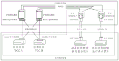
As shown in fig. 7, when the CCS, the interlock device and the TCC device are located in the same building room (i.e. the distance between the two is less than 1km), the CCS host system (e.g. two CTC servers A, B shown in fig. 7) and the interlock host computer (e.g. the interlocking execution representation machine A, B of the train section shown in fig. 7) and the TCC device (e.g. TCC-A, B of the train section shown in fig. 7) are directly cross-interconnected through serial ports, so as to realize the interface between the CCS and the interlock device and the TCC device.
As shown in fig. 8, the CCS dispatch lobby in the railcar yard is typically in the same building as the CCS system room, but may not be in the same building as the signal room. In this case, various dispatching personnel can concentrate on the CCS dispatching hall for work, and in order to ensure timely operation in the "abnormal stop control" mode after the CCS system fails, it is considered that the interlocking system is provided with a remote control terminal in the CCS hall, and a remote control background device (as shown in fig. 8, an interlocking remote control display, that is, a remote interlocking control device) is provided in the CCS machine room. In this case, the CCS and the interlocking device may perform local serial port cross-connection through the interlocking remote control system in the CCS room (i.e. no connection of any device is added in the middle); optical fibers can be utilized for the TCC equipment, optical fiber converters are additionally arranged on the equipment at two ends, remote serial port cross interconnection is realized by means of optical signal forwarding, and when multimode optical fibers are adopted, the distance between the two equipment is allowed to be not more than 5 km; when a single mode optical fiber is used, the distance between the two devices is allowed to be not more than 10 km.
On the basis of any one of the above embodiments, the serial port is an RS422 serial port.
According to the interface method of the centralized system controlled by the motor train section and the signal system, the station level machine setting of a dispatching and centralized control system (CTC) arranged in the motor train section (station) by the signal system is cancelled, so that the engineering investment can be saved, the equipment configuration can be simplified, and the maintenance workload can be reduced; the interface scheme provided by the patent simplifies the information flow between systems and optimizes the configuration of system software; the complexity of operation and maintenance management caused by the parallel of double system devices and limited information interaction is avoided.
Finally, it should be noted that: the above examples are only intended to illustrate the technical solution of the present invention, but not to limit it; although the present invention has been described in detail with reference to the foregoing embodiments, it will be understood by those of ordinary skill in the art that: the technical solutions described in the foregoing embodiments may still be modified, or some technical features may be equivalently replaced; and such modifications or substitutions do not depart from the spirit and scope of the corresponding technical solutions of the embodiments of the present invention.
Claims (4)
1. A method for interfacing a centralized system controlled by a plurality of motor train units with a signal system, comprising:
s1, expanding the function of the centralized system CCS controlled by the bullet train section to enable the CCS to have all functions of the CTC extension equipment in the dispatching and centralized control system in the signal system and cancel the CTC extension equipment; the signal system also comprises interlocking equipment and train control center TCC equipment in the motor train section and central equipment in a dispatching center (CTC) in the motor train section;
s2, transforming the information flow of the CCS and the signal system to enable the train operation plan issued by the CTC central equipment to be directly sent to the interlocking equipment through the CCS;
s3, modifying the interface position and interface mode of CCS and signal system, using the interface of original CTC extension equipment and CTC center equipment, original CTC extension equipment and interlock equipment, and original CTC extension equipment and TCC equipment to realize the interface of CCS and signal system equipment, and constructing the connection of CCS and CTC center equipment, interlock equipment and TCC equipment;
the step of constructing the connection between the CCS, the interlock device and the TCC device in S3 specifically includes:
cross-connecting CCS, interlocking equipment and TCC equipment through dual redundant serial ports;
developing interfaces of CCS and interlocking equipment and TCC equipment, wherein the interface standard is consistent with the interface standard of the original CTC extension equipment and interlocking equipment and TCC equipment; the interfaces of the interlocking equipment and the TCC equipment side both utilize the original interface with CTC extension equipment;
if the distances between the CCS and the interlocking equipment and between the CCS and the TCC equipment are smaller than the distance threshold value, the CCS is respectively connected with the interlocking equipment and the TCC equipment through a local serial port;
otherwise, connecting the CCS with the interlocking equipment and the TCC equipment through the optical fibers; when the interlocking remote control device is arranged near the CCS device, the CCS is connected with the interlocking remote control device through the local serial port to realize an interface between the CCS and the interlocking device.
2. The method of claim 1, wherein said step of providing the CCS with full functionality of CTC extension devices in a dispatch set in a signaling system in S1 specifically comprises:
the route plan validity checking function, the car number processing function, the route restriction and trigger time function and the route forecasting function in the CCS are consistent with the corresponding functions of the CTC extension equipment in a logic processing mode;
and a driving auxiliary alarm function, a construction logging management and recording function, a display and operation representation function, an adjacent station display function and a TCC (transmission control function) interface function are added in the CCS.
3. The method of claim 1 or 2, wherein the step of expanding the functionality of the CCS of the centralized system controlled by the train section in S1 to provide the CCS with the full functionality of the dispatch centralized CTC extension device in the signaling system specifically comprises:
a CTC server is added in the CCS, and all functions of CTC extension equipment are expanded to the CTC server; alternatively, the full functionality of the CTC extension device is extended to the application server in the CCS.
4. The method according to claim 1, wherein the step of constructing in S3 the connection of the CCS with the CTC central device comprises in particular:
setting double sets of routers in a local area network of a CCS;
connecting the router with CTC central equipment by adopting a redundant 2M special line channel between original CTC extension equipment and CTC central equipment;
the interface standard between CCS and CTC central equipment is consistent with that between original CTC extension equipment and CTC central equipment.
Priority Applications (1)
| Application Number | Priority Date | Filing Date | Title |
|---|---|---|---|
| CN201810046152.3A CN108327747B (en) | 2018-01-17 | 2018-01-17 | Interface method for centralized system controlled by motor train section and signal system |
Applications Claiming Priority (1)
| Application Number | Priority Date | Filing Date | Title |
|---|---|---|---|
| CN201810046152.3A CN108327747B (en) | 2018-01-17 | 2018-01-17 | Interface method for centralized system controlled by motor train section and signal system |
Publications (2)
| Publication Number | Publication Date |
|---|---|
| CN108327747A CN108327747A (en) | 2018-07-27 |
| CN108327747B true CN108327747B (en) | 2020-04-21 |
Family
ID=62925119
Family Applications (1)
| Application Number | Title | Priority Date | Filing Date |
|---|---|---|---|
| CN201810046152.3A Active CN108327747B (en) | 2018-01-17 | 2018-01-17 | Interface method for centralized system controlled by motor train section and signal system |
Country Status (1)
| Country | Link |
|---|---|
| CN (1) | CN108327747B (en) |
Families Citing this family (5)
| Publication number | Priority date | Publication date | Assignee | Title |
|---|---|---|---|---|
| CN112606872B (en) * | 2020-12-27 | 2022-08-26 | 卡斯柯信号有限公司 | Wireless route advance notice improvement method for dispatching centralized system |
| CN113162988A (en) * | 2021-03-27 | 2021-07-23 | 卡斯柯信号有限公司 | Interface system for communication between dispatching centralized system and interlocking system |
| CN113830140B (en) * | 2021-08-12 | 2023-09-26 | 中铁建电气化局集团南方工程有限公司 | High-speed railway junction station signal system transformation implementation method |
| CN115257877B (en) * | 2022-07-27 | 2023-12-01 | 卡斯柯信号有限公司 | Station train control system and interface method of automatic train monitoring system and interlocking lower computer thereof |
| CN119840690B (en) * | 2025-03-18 | 2025-06-27 | 中国铁道科学研究院集团有限公司通信信号研究所 | Method and system for disabling traffic dispatching service in high-speed railway skylight based on CTC |
Family Cites Families (4)
| Publication number | Priority date | Publication date | Assignee | Title |
|---|---|---|---|---|
| JPH09326817A (en) * | 1996-06-06 | 1997-12-16 | West Japan Railway Co | Data transmitter for vehicle control |
| JP3455794B2 (en) * | 1996-11-19 | 2003-10-14 | 株式会社日立製作所 | Train operation management system |
| CN104859683B (en) * | 2015-05-26 | 2016-08-31 | 北京交通大学 | A kind of ground installation of high speed train control system |
| CN104908783B (en) * | 2015-05-27 | 2017-01-18 | 中国铁路总公司 | System architecture of comprehensive monitoring and maintaining system for railway electricity |
-
2018
- 2018-01-17 CN CN201810046152.3A patent/CN108327747B/en active Active
Also Published As
| Publication number | Publication date |
|---|---|
| CN108327747A (en) | 2018-07-27 |
Similar Documents
| Publication | Publication Date | Title |
|---|---|---|
| CN108327747B (en) | Interface method for centralized system controlled by motor train section and signal system | |
| CN109693690B (en) | Maglev operation control system | |
| CN102320316B (en) | CTCS-3-level train control center system | |
| CN107403580B (en) | Railway signal integrated system experiment platform | |
| CN101537847B (en) | Realization method of train operation control system with a speed of 200-350 kilometers per hour | |
| EP3763598A1 (en) | Centralized train dispatch control system and control method | |
| CN100463822C (en) | A computer interlocking system | |
| CN110435723A (en) | A kind of Distributed Area computer interlock system | |
| CN112590885B (en) | Urban railway signal control system | |
| CN113353128B (en) | High-speed magnetic levitation running control system | |
| CN104960554B (en) | Station interval integrated system provided with double hosts based on functional allocation | |
| CN110712667A (en) | Comprehensive train control system capable of adapting to foreign requirements | |
| CN112622983A (en) | Re-connectable communication network architecture based on train and communication method thereof | |
| CN107953903B (en) | Communication system, scheduling centralized system, train control center and readable storage medium | |
| CN212500426U (en) | Train autonomous control system based on vehicle-to-vehicle communication | |
| CN118790322A (en) | A kind of conventional railway station interlocking route information security transmission equipment | |
| JP2000159108A (en) | Equipment decentralized electronic interlocking device | |
| CN112896245A (en) | Medium-low traffic volume rail transit signal system | |
| CN117104316A (en) | A format conversion system suitable for urban rail transit and municipal railway cross-line operations | |
| CN112783036B (en) | Automatic train control system | |
| CN114834506B (en) | Wireless block center equipment suitable for heavy-load railway | |
| Fukuta et al. | Novel railway signal control system based on the internet technology and its distributed control architecture | |
| CN112874574A (en) | Distributed intelligent switch machine control system | |
| CN117215290A (en) | High-speed railway signal system engineering test platform | |
| CN115180003B (en) | Electronic execution unit and redundancy system for railway signal coded fault-oriented safety coding |
Legal Events
| Date | Code | Title | Description |
|---|---|---|---|
| PB01 | Publication | ||
| PB01 | Publication | ||
| SE01 | Entry into force of request for substantive examination | ||
| SE01 | Entry into force of request for substantive examination | ||
| GR01 | Patent grant | ||
| GR01 | Patent grant |