CN107851549B - Multi-reflection TOF mass spectrometer - Google Patents
Multi-reflection TOF mass spectrometer Download PDFInfo
- Publication number
- CN107851549B CN107851549B CN201680034050.9A CN201680034050A CN107851549B CN 107851549 B CN107851549 B CN 107851549B CN 201680034050 A CN201680034050 A CN 201680034050A CN 107851549 B CN107851549 B CN 107851549B
- Authority
- CN
- China
- Prior art keywords
- ion
- ions
- dimension
- mirrors
- mass spectrometer
- Prior art date
- Legal status (The legal status is an assumption and is not a legal conclusion. Google has not performed a legal analysis and makes no representation as to the accuracy of the status listed.)
- Active
Links
Images


Classifications
-
- H—ELECTRICITY
- H01—ELECTRIC ELEMENTS
- H01J—ELECTRIC DISCHARGE TUBES OR DISCHARGE LAMPS
- H01J49/00—Particle spectrometers or separator tubes
- H01J49/26—Mass spectrometers or separator tubes
- H01J49/34—Dynamic spectrometers
- H01J49/40—Time-of-flight spectrometers
- H01J49/406—Time-of-flight spectrometers with multiple reflections
-
- H—ELECTRICITY
- H01—ELECTRIC ELEMENTS
- H01J—ELECTRIC DISCHARGE TUBES OR DISCHARGE LAMPS
- H01J49/00—Particle spectrometers or separator tubes
- H01J49/0027—Methods for using particle spectrometers
- H01J49/0031—Step by step routines describing the use of the apparatus
-
- H—ELECTRICITY
- H01—ELECTRIC ELEMENTS
- H01J—ELECTRIC DISCHARGE TUBES OR DISCHARGE LAMPS
- H01J49/00—Particle spectrometers or separator tubes
- H01J49/02—Details
- H01J49/06—Electron- or ion-optical arrangements
- H01J49/061—Ion deflecting means, e.g. ion gates
-
- H—ELECTRICITY
- H01—ELECTRIC ELEMENTS
- H01J—ELECTRIC DISCHARGE TUBES OR DISCHARGE LAMPS
- H01J49/00—Particle spectrometers or separator tubes
- H01J49/26—Mass spectrometers or separator tubes
- H01J49/34—Dynamic spectrometers
- H01J49/40—Time-of-flight spectrometers
- H01J49/405—Time-of-flight spectrometers characterised by the reflectron, e.g. curved field, electrode shapes
-
- H—ELECTRICITY
- H01—ELECTRIC ELEMENTS
- H01J—ELECTRIC DISCHARGE TUBES OR DISCHARGE LAMPS
- H01J49/00—Particle spectrometers or separator tubes
- H01J49/26—Mass spectrometers or separator tubes
- H01J49/34—Dynamic spectrometers
- H01J49/42—Stability-of-path spectrometers, e.g. monopole, quadrupole, multipole, farvitrons
- H01J49/4205—Device types
- H01J49/4245—Electrostatic ion traps
-
- H—ELECTRICITY
- H01—ELECTRIC ELEMENTS
- H01J—ELECTRIC DISCHARGE TUBES OR DISCHARGE LAMPS
- H01J49/00—Particle spectrometers or separator tubes
- H01J49/26—Mass spectrometers or separator tubes
- H01J49/34—Dynamic spectrometers
- H01J49/42—Stability-of-path spectrometers, e.g. monopole, quadrupole, multipole, farvitrons
- H01J49/426—Methods for controlling ions
Landscapes
- Chemical & Material Sciences (AREA)
- Analytical Chemistry (AREA)
- Other Investigation Or Analysis Of Materials By Electrical Means (AREA)
- Electron Tubes For Measurement (AREA)
Abstract
Description
相关申请的交叉引用CROSS-REFERENCE TO RELATED APPLICATIONS
本申请要求于2015年4月30日提交的英国专利申请号1507363.8的优先权和权益,其全部内容通过引用并入本文。This application claims priority to and the benefit of UK Patent Application No. 1507363.8, filed 30 April 2015, the entire contents of which are incorporated herein by reference.
技术领域technical field
本发明一般涉及质谱仪,并且特别涉及多反射飞行时间质谱仪(MR-TOF-MS)及其使用方法。The present invention relates generally to mass spectrometers, and in particular to multi-reflection time-of-flight mass spectrometers (MR-TOF-MS) and methods of their use.
背景技术Background technique
飞行时间质谱仪是广泛使用的分析化学工具,其特征在于在宽的质量范围内高速分析。已经认识到,由于通过在离子光学元件之间使用多次反射提供的飞行路径延伸,多反射飞行时间质谱仪(MR-TOF-MS)提供了分辨力的显著提高。飞行路径中的这种延伸要求例如如在GB 2080021中所述的通过在离子反射镜中反射离子或者例如如在Toyoda等人的质谱法杂志(J.Mass Spectrometry)38(2003)1125中描述的通过在扇形区中偏转离子以折叠离子路径。使用离子反射镜的MR-TOF-MS仪器由于具有高阶次的每时1间能量和每个空间时间的离散离子聚焦而提供更大的能量和空间接受度的重要优势。Time-of-flight mass spectrometers are widely used analytical chemistry tools characterized by high-speed analysis over a wide mass range. It has been recognized that multi-reflection time-of-flight mass spectrometry (MR-TOF-MS) provides a significant increase in resolution due to the flight path extension provided by the use of multiple reflections between ion optics. This extension in the flight path requires eg by reflecting the ions in an ion mirror as described in GB 2080021 or eg as described in Toyoda et al. J. Mass Spectrometry 38 (2003) 1125 The ion paths are folded by deflecting the ions in a sector. MR-TOF-MS instruments using ion mirrors offer the important advantage of greater energy and spatial acceptance due to higher order energies per time and discrete ion focusing per space time.
尽管MR-TOF-MS仪器从根本上提供了延长的飞行路径和高分辨率,但是它们通常不提供足够的灵敏度,因为用于将离子注入飞行路径中的正交加速器导致在小尺寸离子包和延长的飞行时间的占空比下降。Although MR-TOF-MS instruments fundamentally offer extended flight paths and high resolution, they generally do not provide sufficient sensitivity because the orthogonal accelerators used to inject ions into the flight path result in small size ion packets and The duty cycle decreases for extended flight time.
SU 1725289引入了图1所示类型的折叠路径平面MR-TOF-MS仪器。该仪器包括沿漂移Z方向延伸以反射离子的两个二维无网格离子反射镜12、用于注入离子到装置中的正交加速器13,以及用于检测离子的检测器14。为了清楚起见,在该整个文本中,平面MR-TOF-MS仪器在标准笛卡尔坐标系中描述。也就是说,X轴对应于飞行时间的方向,即离子反射镜之间的离子反射的方向。Z轴对应于离子的漂移方向。Y轴与X轴和Z轴都是正交的。SU 1725289 introduced a folded path planar MR-TOF-MS instrument of the type shown in Figure 1. The instrument includes two two-dimensional
参考图1,在使用中,离子通过加速器13以相对于X轴的倾斜角α朝离子反射镜12中的一个加速。因此离子在X方向中具有速度并且在Z方向中还具有漂移速度。当离子在Z方向中沿着装置漂移,直到离子撞击检测器14为止,离子在两个离子反射镜12之间连续反射。因此离子遵循X-Z平面内的锯齿形(线锯)平均轨迹。离子沿每次反射镜反射的Z方向前进增量ZR=C*sinα,其中C是离子反射镜中相邻反射点之间的飞行路径。然而,在漂移Z方向中没有提供离子聚焦,并且因此离子包在漂移Z方向中发散。理论上可以在离子反射镜12之间引入低发散离子包,以便在离子在漂移Z方向中重叠之前允许大约20m的离子飞行路径,从而实现100000和200000之间的质量分辨能力。然而,实际上,不可能将离子包注入到在Z方向中比几毫米更长的反射镜12之间的空间中,而不会有离子撞击正交加速器13,因为它们在装置中振荡。这个缺点将光谱仪的占空比限于在100,000的质量分辨率下小于0.5%。Referring to Figure 1, in use, ions are accelerated by
WO 2005/001878提出在无场区域内提供一组周期性透镜,以便通过防止离子束在Z方向中发散来克服上述问题,从而允许离子飞行路径延伸并且光谱仪分辨率提高。WO 2005/001878 proposes to provide a set of periodic lenses in the field-free region in order to overcome the above-mentioned problems by preventing the ion beam from spreading in the Z-direction, thereby allowing the ion flight path to be extended and the spectrometer resolution to be improved.
WO 2007/044696进一步提出使正交加速器基本上正交于分析仪的离子路径平面,以便减小周期性透镜的像差,同时改善正交加速器的占空比。这种技术利用离子反射镜的较小空间Y像差对周期性透镜的Z像差。然而,正交加速器的占空比在分析仪分辨率为100,000时仍然被限制在约0.5%。WO 2007/044696 further proposes to make the orthogonal accelerator substantially orthogonal to the plane of the ion path of the analyzer in order to reduce the aberrations of the periodic lens while improving the duty cycle of the orthogonal accelerator. This technique exploits the smaller spatial Y aberration of the ion mirror versus the Z aberration of the periodic lens. However, the duty cycle of the orthogonal accelerator is still limited to about 0.5% at an analyzer resolution of 100,000.
为了进一步改善MR-TOF-MS的占空比,WO 2011/107836介绍了可替代的方法。该方法使用所谓的开放式阱分析仪,其中反射次数不固定,频谱由对应于一定范围的离子反射的信号多重谱组成,并且通过解码多重信号恢复飞行时间频谱。这种配置允许正交加速器和检测器两者的拉伸,从而增强占空比。To further improve the duty cycle of MR-TOF-MS, WO 2011/107836 introduces an alternative approach. The method uses a so-called open trap analyzer, where the number of reflections is not fixed, the spectrum consists of signal multiplets corresponding to a range of ion reflections, and the time-of-flight spectrum is recovered by decoding the multiples. This configuration allows stretching of both the orthogonal accelerator and detector, thereby enhancing the duty cycle.
如WO 2011/107836和WO 2011/135477中所述,正交加速度占空比的进一步改进可以通过使用频率编码脉冲接着是频谱解码的步骤来实现。由于频谱解码步骤在很大程度上依赖于稀疏质谱群体,所以这两种技术都特别适合与高分辨率MR-TOF-MS仪器(例如R~100,000)组合的串联质谱法。然而,这些技术都限制了仅MS分析仪的动态范围,因为在主要信号中发生在1E-3到1E-4的水平的化学背景噪声时,频谱群体变成问题。As described in WO 2011/107836 and WO 2011/135477, a further improvement of the quadrature acceleration duty cycle can be achieved by using a frequency encoding pulse followed by a spectral decoding step. Since the spectral decoding step relies heavily on sparse mass spectral populations, both techniques are particularly suitable for tandem mass spectrometry in combination with high-resolution MR-TOF-MS instruments (eg, R~100,000). However, these techniques all limit the dynamic range of MS-only analyzers because spectral populations become problematic when chemical background noise at levels 1E-3 to 1E-4 occurs in the main signal.
GB 2476964和WO 2011/086430提出在漂移Z方向中弯曲离子反射镜,从而形成空心圆柱形静电离子阱或MR-TOF分析仪,其允许离子飞行路径的进一步延伸以获得更高的质量分辨能力,并且还允许在Z方向中扩展离子包尺寸以改进正交加速器占空比。在圆柱形MR-TOF中长得多的飞行路径处,质量分辨能力不再受到离子包的初始时间扩展的限制,而是受到分析仪像差的限制。飞行时间(TOF)的像差主要是由于:(i)在飞行方向X中的离子能量K扩展;(ii)离子包在Y方向中的空间扩展;以及(iii)离子包在漂移Z方向中的空间扩展,引起周期性透镜的球面像差。GB 2476964 and WO 2011/086430 propose to bend ion mirrors in the drift Z direction, thereby forming a hollow cylindrical electrostatic ion trap or MR-TOF analyzer, which allows further extension of the ion flight path for higher mass resolution capabilities, And also allows to expand the ion packet size in the Z direction to improve the orthogonal accelerator duty cycle. At much longer flight paths in cylindrical MR-TOFs, the mass resolving power is no longer limited by the initial time spread of the ion packets, but by analyzer aberrations. Time-of-flight (TOF) aberrations are mainly due to: (i) ion energy K expansion in the flight direction X; (ii) spatial expansion of ion packets in the Y direction; and (iii) ion packets in the drift Z direction The spatial expansion of the periodic lens causes spherical aberration.
尽管周期性透镜的像差是分析仪的主要剩余TOF像差,但WO 2013/063587改进了关于能量K和Y扩展的离子反射镜等时性。为了减小这些透镜像差,US 2011/186729公开了所谓的准平面离子反射镜,即空间调制的离子反射镜场。然而,如果在Z方向中的静电场调制的周期与反射镜窗口的Y高度相当或者大于Y高度时,才能够实现此类反射镜中的TOF像差的有效消除。这在实际的分析仪尺寸下强烈地限制了离子轨迹折叠和飞行路径延伸的密度。此外,Z方向中的周期性调制也影响场的Y分量,这使分析仪调谐变得复杂。因此,WO2011/08643的圆柱形分析仪、WO 2013/063587的改进的反射镜和US 2011/186729的准平面分析仪允许正交加速器长度的一些延伸以便提供更高的占空比,但资源非常有限。Although aberrations of periodic lenses are the main residual TOF aberrations of the analyzer, WO 2013/063587 improves the ion mirror isochronism with respect to energy K and Y spread. To reduce these lens aberrations, US 2011/186729 discloses so-called quasi-planar ion mirrors, ie spatially modulated ion mirror fields. However, effective cancellation of TOF aberrations in such mirrors can only be achieved if the period of the electrostatic field modulation in the Z direction is comparable to or greater than the Y height of the mirror window. This strongly limits the density of ion trajectory folding and flight path extension at practical analyzer dimensions. In addition, periodic modulation in the Z direction also affects the Y component of the field, which complicates analyzer tuning. Thus, the cylindrical analyzer of WO 2011/08643, the improved mirror of WO 2013/063587 and the quasi-planar analyzer of US 2011/186729 allow some extension of the orthogonal accelerator length in order to provide a higher duty cycle, but the resources are very limited.
因此,现有技术MR-TOF-MS仪器努力提供高灵敏度和高分辨率仪器。Therefore, prior art MR-TOF-MS instruments strive to provide high sensitivity and high resolution instruments.
期望提供一种改进的光谱仪和一种改进的光谱测定方法。It would be desirable to provide an improved spectrometer and an improved spectroscopic method.
发明内容SUMMARY OF THE INVENTION
本发明提供了一种多反射飞行时间质谱仪(MR TOF MS),包括:The present invention provides a multi-reflection time-of-flight mass spectrometer (MR TOF MS), comprising:
两个离子反射镜,它们在第一维度(X维度)中彼此间隔开,并且每个离子反射镜在与第一维度正交的第二维度(Z维度)中拉伸;two ion mirrors spaced apart from each other in a first dimension (X dimension) and each ion mirror stretched in a second dimension (Z dimension) orthogonal to the first dimension;
离子引入机构,用于将离子包引入到反射镜之间的空间中,使得它们沿着与第一维度和第二维度成角度布置的轨迹行进,使得当它们在第二维度(Z维度)中漂移通过所述空间时离子在反射镜之间在第一维度(X维度)中反复振荡;An ion introduction mechanism for introducing ion packets into the space between the mirrors such that they travel along trajectories arranged at an angle to the first dimension and the second dimension such that when they are in the second dimension (Z dimension) The ions oscillate repeatedly in the first dimension (X dimension) between mirrors as they drift through the space;
其中反射镜和离子引入机构被布置和配置成使得当离子在第二维度(Z维度)中漂移通过所述空间时,离子也在与第一维度和第二维度两者正交的第三维度(Y维度)中振荡;wherein the mirrors and ion introduction mechanism are arranged and configured such that when ions drift through the space in a second dimension (Z dimension), ions are also in a third dimension orthogonal to both the first and second dimensions (Y dimension) in oscillation;
其中光谱仪包括离子接收机构,离子接收机构被布置用于在离子已经在第一维度(X维度)中多次振荡之后接收离子;以及wherein the spectrometer comprises an ion receiving mechanism arranged to receive the ions after the ions have oscillated in the first dimension (X dimension) a number of times; and
其中离子引入机构的至少一部分和/或离子接收机构的至少一部分布置在反射镜之间。Wherein at least a part of the ion introduction mechanism and/or at least a part of the ion reception mechanism is arranged between the mirrors.
当本发明使离子在第三维度(Y维度)中振荡时,离子在第一维度(X维度)中在离子反射镜之间反射时能够绕过离子引入机构和/或离子接收机构。这样,在由离子反射镜中的一个离子反射镜的每次反射期间离子在第二维度(Z维度)中行进的距离可以小于离子引入机构的所述至少一部分的长度和/或离子接收机构的所述至少一部分的长度(长度在第二维度中确定),而离子不冲击离子引入机构和/或离子接收机构。这样,对于在第二维度(Z维度)中具有给定长度的分析仪,离子能够在第一维度(X维度)中执行相对大量的振荡,由此提供相对较长的离子飞行时间路径长度和分析仪的高分辨率。When the present invention oscillates ions in the third dimension (Y dimension), ions can bypass the ion introduction mechanism and/or the ion receiving mechanism when reflected between ion mirrors in the first dimension (X dimension). In this way, the distance the ions travel in the second dimension (Z dimension) during each reflection by one of the ion mirrors may be less than the length of the at least a portion of the ion introduction mechanism and/or the length of the ion receiving mechanism The length of the at least a portion (the length is determined in the second dimension) without the ions impacting the ion introducing mechanism and/or the ion receiving mechanism. In this way, for an analyzer with a given length in the second dimension (Z dimension), the ions are able to perform a relatively large number of oscillations in the first dimension (X dimension), thereby providing a relatively long ion time-of-flight path length and The high resolution of the analyzer.
而且,由于离子在离子反射镜之间在第一维度(X维度)中来回反射,所以离子引入机构能够具有相对较长的第二维度(Z维度)中的长度,而离子不冲击离子引入机构。这使得该装置能够具有改进的占空比和减小的空间电荷效应。Also, since ions are reflected back and forth in the first dimension (X dimension) between ion mirrors, the ion introduction mechanism can have a relatively long length in the second dimension (Z dimension) without ions striking the ion introduction mechanism . This enables the device to have an improved duty cycle and reduced space charge effects.
使用相对较长的离子引入机构能够在第二维度(Z维度)中引入具有较长长度的离子包。因此,与离子包的长度相比,离子包在第二维度(Z维度)中的扩展或发散相对较小。这样,光谱仪可以不包括从离子引入机构到离子接收机构(例如,在第二维度中聚焦离子的透镜)的离子飞行路径中的离子光学透镜。这避免了由此类透镜引起的像差。Using a relatively long ion introduction mechanism enables the introduction of ion packets with longer lengths in the second dimension (Z dimension). Therefore, the spread or divergence of the ion packets in the second dimension (the Z dimension) is relatively small compared to the length of the ion packets. As such, the spectrometer may not include an ion optical lens in the ion flight path from the ion introduction mechanism to the ion receiving mechanism (eg, a lens that focuses the ions in the second dimension). This avoids aberrations caused by such lenses.
本发明还使得离子接收机构能够具有相对较长的第二维度(Z维度)中的长度,而离子不冲击离子接收机构,因为离子在离子反射镜之间在第一维度(X维度)中来回反射。例如,如果离子接收机构是检测器,则这可能是有用的,因为它使检测器的使用寿命和动态范围增加。The present invention also enables the ion receiving mechanism to have a relatively long length in the second dimension (Z dimension) without ions hitting the ion receiving mechanism because the ions travel back and forth between ion mirrors in the first dimension (X dimension) reflection. For example, if the ion receiving mechanism is a detector, this may be useful because it increases the lifetime and dynamic range of the detector.
离子反射镜是质谱技术中众所周知的装置,并因此在此不再详细描述。然而,应该理解的是,根据在此描述的实施例,电压被施加到离子反射镜的电极以便生成用于反射离子的电场。离子可以沿着基本上平行于电场方向的轨迹进入离子反射镜,被电场阻碍和转向,并且然后在基本上平行于电场的方向中通过电场加速离开离子反射镜。Ion mirrors are well known devices in mass spectrometry and therefore will not be described in detail here. It should be understood, however, that according to the embodiments described herein, a voltage is applied to the electrodes of the ion mirror in order to generate an electric field for reflecting ions. Ions may enter the ion mirror along a trajectory substantially parallel to the direction of the electric field, be blocked and deflected by the electric field, and then be accelerated away from the ion mirror by the electric field in a direction substantially parallel to the electric field.
GB 2396742(Bruker)和JP 2007227042(Joel)各自公开了一种仪器,其包括由飞行区域分开的两个相对的电扇形区。通过相对的电扇形区以8字形的图案将离子引导通过仪器。然而,这些仪器不具有用于执行反射的两个离子反射镜,并且因此比本发明的基于离子反射镜的系统更不灵活。本领域技术人员将意识到,电扇形区不是离子反射镜。基于Bruker或Joel的教导,本领域技术人员将不会以本申请要求保护的方式利用基于反射镜的MR-TOF-MS仪器克服上述问题,因为Bruker和Joel不涉及装有反射镜的MR-TOF-MS仪器。GB 2396742 (Bruker) and JP 2007227042 (Joel) each disclose an instrument comprising two opposing electrical sectors separated by a flight area. The ions are guided through the instrument in a figure-8 pattern by opposing electrical sectors. However, these instruments do not have two ion mirrors for performing reflections and are therefore less flexible than the ion mirror based systems of the present invention. Those skilled in the art will appreciate that electrical sectors are not ion mirrors. Based on the teachings of Bruker or Joel, one skilled in the art would not overcome the above problems with a mirror-based MR-TOF-MS instrument in the manner claimed in this application, since Bruker and Joel do not address mirrored MR-TOF - MS instrument.
根据本发明的实施例,离子引入机构包括控制器、至少一个电压供应(即,至少一个DC和/或RF电压供应)、电子电路系统和电极。控制器可以包括处理器,所述处理器被布置和配置成控制电压供应以经由电路系统向电极施加电压,以便沿着与第一维度和第二维度成一定角度的所述轨迹将离子脉冲到离子反射镜中的一个。处理器还可以被布置和配置成控制电压供应以经由电路系统向电极施加电压,以便将离子脉冲到离子反射镜中的一个并且相对于镜轴以一定角度或位置将离子脉冲,使得离子在第三维度(Y维度)中振荡。可替代地或附加地,光谱仪还包括控制器、至少一个电压供应(即,至少一个DC和/或RF电压供应)、电子电路系统和电极,以用于经由电路系统控制施加到镜电极的电压以便使离子在第三维度(Y维度)中振荡。According to an embodiment of the invention, the ion introduction mechanism includes a controller, at least one voltage supply (ie, at least one DC and/or RF voltage supply), electronic circuitry and electrodes. The controller may comprise a processor arranged and configured to control the voltage supply to apply the voltage to the electrodes via the circuitry to pulse the ions along the trajectory at an angle to the first dimension and the second dimension to the electrode. One of the ion mirrors. The processor may also be arranged and configured to control the voltage supply to apply a voltage to the electrodes via the circuitry to pulse the ions to one of the ion mirrors and to pulse the ions at an angle or position relative to the mirror axis such that the ions are in the first mirror. Oscillate in three dimensions (Y dimension). Alternatively or additionally, the spectrometer further comprises a controller, at least one voltage supply (ie, at least one DC and/or RF voltage supply), electronic circuitry and electrodes for controlling the voltage applied to the mirror electrodes via the circuitry in order to oscillate the ions in the third dimension (Y dimension).
离子可围绕轴线在第三维度(Y维度)以及在最大幅度的位置之间振荡,并且离子引入机构的所述至少一部分和/或离子接收机构的所述至少一部分可以布置成仅在最大幅度的位置之间的空间的仅一部分上延伸。这允许离子行进穿过离子引入机构和/或离子接收机构不位于其的空间,由此在第一维度(X维度)中在振荡中的至少一些期间绕过这两个元件中的一个。The ions may oscillate about the axis between a third dimension (the Y dimension) and a position of maximum amplitude, and said at least a portion of the ion introduction mechanism and/or said at least a portion of the ion receiving mechanism may be arranged only at a maximum amplitude. Only a portion of the space between the locations extends. This allows ions to travel through the space where the ion introducing mechanism and/or ion receiving mechanism is not located, thereby bypassing one of these two elements during at least some of the oscillations in the first dimension (X dimension).
当在此指代离子引入机构的所述至少一部分的位置和尺寸时,这些可以指代布置在最大幅度的位置之间的离子引入机构的部分的位置和尺寸。类似地,当在此指代离子接收机构的所述至少一部分的位置和尺寸时,这些可以指代布置在最大幅度的位置之间的离子接收机构的部分的位置和尺寸。When referring herein to the position and size of the at least part of the ion introduction mechanism, these may refer to the position and size of the portion of the ion introduction mechanism that is arranged between the positions of maximum amplitude. Similarly, when referring herein to the position and size of the at least a portion of the ion receiving mechanism, these may refer to the position and size of the portion of the ion receiving mechanism that is arranged between the positions of maximum amplitude.
离子反射镜和离子引入机构可以被配置成使得离子在第一维度(X维度)中的反射镜之间的离子的每次反射期间在第二维度(Z维度)中行进距离ZR;其中距离ZR小于离子引入机构的所述至少一部分的第二维度(Z维度)中的长度和/或离子接收机构的所述至少一部分的第二维度(Z维度)中的长度。离子引入机构的所述至少一部分的第二维度(Z维度)中的长度可以是布置在反射镜之间的离子引入机构的一部分的长度,或者是布置在最大幅度的所述位置之间的离子引入机构的一部分的长度。类似地,离子接收机构的所述至少一部分的第二维度(Z维度)中的长度可以是布置在反射镜之间的离子接收机构的一部分的长度,或者可以是布置在最大幅度的所述位置之间的离子接收机构的一部分的长度。The ion mirrors and ion introduction mechanism may be configured such that ions travel a distance Z R in the second dimension (Z dimension) during each reflection of ions between mirrors in the first dimension (X dimension); where the distance Z R is less than the length in the second dimension (Z dimension) of the at least part of the ion introduction mechanism and/or the length in the second dimension (Z dimension) of the at least part of the ion receiving mechanism. The length in the second dimension (Z dimension) of the at least part of the ion introduction mechanism may be the length of the part of the ion introduction mechanism arranged between the mirrors, or the ions arranged between said positions of maximum amplitude The length of the part of the introduction body. Similarly, the length in the second dimension (Z dimension) of the at least a portion of the ion-receiving mechanism may be the length of the portion of the ion-receiving mechanism disposed between the mirrors, or may be the location at which the greatest magnitude is disposed The length of the part of the ion receiving mechanism between.
可选地,离子引入机构的所述至少一部分的第二维度(Z维度)中的长度和/或离子接收机构的所述至少一部分的第二维度(Z维度)中的长度高达距离ZR的四倍Optionally, the length in the second dimension (Z dimension) of said at least a portion of the ion introduction mechanism and/or the length in the second dimension (Z dimension) of said at least a portion of the ion receiving mechanism is up to a distance of Z R . four times
离子反射镜和离子引入机构可被配置成使得离子在第一维度(X维度)和第三维度(Y维度)中以一定速率振荡,使得当离子在第一维度和第二维度(X和Z维度)中具有与离子引入机构的所述至少一部分相同的位置时,离子在第三维度(Y维度)中具有不同的位置,使得当离子在第一维度(X维)中振荡时,离子的轨迹绕过离子引入机构至少一次。The ion mirror and ion introduction mechanism may be configured such that the ions oscillate in the first dimension (X dimension) and the third dimension (Y dimension) at a rate such that when the ions are in the first dimension and the second dimension (X and Z dimension) dimension) having the same position as the at least part of the ion introduction mechanism, the ion has a different position in the third dimension (Y dimension), such that when the ion oscillates in the first dimension (X dimension), the The trajectory bypasses the ion introduction mechanism at least once.
可替代地或另外地,离子反射镜和离子引入机构可被配置成使得离子在第一维度(X维度)和第三维度(Y维度)中以一定速率振荡,使得当离子在第一维度和第二维度(X和Z方向)中具有与离子接收机构的所述至少一部分相同的位置时,离子在第三维度(Y维度)中具有不同的位置,使得当它们在第一维度(X维度)中振荡时离子的轨迹绕过离子接收机构至少一次。Alternatively or additionally, the ion mirror and ion introduction mechanism may be configured such that the ions oscillate in the first dimension (X dimension) and the third dimension (Y dimension) at a rate such that when the ions are in the first dimension and While having the same position in the second dimension (X and Z directions) as the at least part of the ion receiving mechanism, the ions have different positions in the third dimension (Y dimension) such that when they are in the first dimension (X dimension) ), the trajectory of the ion bypasses the ion receiving mechanism at least once.
反射镜和离子引入机构可被配置成使得离子以选自如下组成的组的幅度在第三维度(Y维度)中振荡:≥0.5mm;≥1mm;≥1.5mm;≥2mm;≥2.5mm;≥3mm;≥3.5mm;≥4mm;≥4.5mm;≥5mm;≥6mm;≥7mm;≥8mm;≥9mm;≤10mm;≤9mm;≤8mm;≤7mm;≤6mm;≤5mm;≤4.5mm;≤4mm;≤3.5mm;≤3mm;≤2.5mm;以及≤2mm。离子可以在由上述范围的组合中的任一个限定的范围内的幅度在第三维度(Y维度)中振荡。The mirror and ion introduction mechanism may be configured such that the ions oscillate in the third dimension (Y dimension) with an amplitude selected from the group consisting of: ≥ 0.5 mm; ≥ 1 mm; ≥ 1.5 mm; ≥ 2 mm; ≥ 2.5 mm; ≥3mm; ≥3.5mm; ≥4mm; ≥4.5mm; ≥5mm; ≥6mm; ≥7mm; ≥8mm; ≥9mm; ≤10mm; ≤9mm; ≤8mm; ≤7mm; ≤6mm; ≤5mm; ≤4.5mm ; ≤4mm; ≤3.5mm; ≤3mm; ≤2.5mm; and ≤2mm. The ions may oscillate in the third dimension (the Y dimension) with amplitudes within the ranges defined by any of the above-mentioned combinations of ranges.
本发明人已经认识到,分析仪像差可以随着第三维度(Y维度)中的离子位移的幅度而快速增长。因此可能期望保持离子包在第三维度(Y维度)中的适度位移。The inventors have recognized that analyzer aberrations can grow rapidly with the magnitude of the ion displacement in the third dimension (the Y dimension). It may therefore be desirable to maintain a modest displacement of the ion packets in the third dimension (Y dimension).
为了在第三维度(Y维度)中实现适度位移,离子引入机构或离子接收机构可以在第三维度(Y维度)中相对较窄。例如,这些部件可以使用电阻板形成。离子引入机构或离子接收机构可以具有在选自如下组成的组中的在第三维度(Y维度)中的宽度:≤10mm;≤9mm;≤8mm;≤7mm;≤6mm;≤5mm;≤4.5mm;≤4mm;≤3.5mm;≤3mm;≤2.5mm;以及≤2mm。To achieve moderate displacement in the third dimension (Y dimension), the ion introducing mechanism or ion receiving mechanism may be relatively narrow in the third dimension (Y dimension). For example, these components may be formed using resistive plates. The ion introducing mechanism or the ion receiving mechanism may have a width in the third dimension (Y dimension) selected from the group consisting of: ≤ 10 mm; ≤ 9 mm; ≤ 8 mm; ≤ 7 mm; ≤ 6 mm; ≤ 5 mm; ≤ 4.5 ≤4mm; ≤3.5mm; ≤3mm; ≤2.5mm; and ≤2mm.
离子围绕具有最大振荡幅度的轴线在第三维度(Y维度)中振荡,并且离子引入机构的所述至少一部分和/或离子接收机构的所述至少一部分可以在第三维度(Y维度)中间隔开小于最大振荡幅度的距离。The ions oscillate in the third dimension (the Y dimension) about the axis having the greatest amplitude of oscillation, and the at least a portion of the ion introduction mechanism and/or the at least a portion of the ion receiving mechanism may be spaced in the third dimension (the Y dimension) open a distance less than the maximum oscillation amplitude.
可选地,反射镜和离子引入机构可以被配置成使得离子以选自如下组成的组的幅度在第一维度(X维度)中振荡:≥0.5mm;≥1mm;≥1.5mm;≥2mm;≥2.5mm;≥3mm;≥3.5mm;≥4mm;≥4.5mm;≥5mm;7.5mm;10mm;15mm;20mm;≤20mm;≤15mm;≤10mm;≤9mm;≤8mm;≤7mm;≤6mm;≤5mm;≤4.5mm;≤4mm;≤3.5mm;≤3mm;≤2.5mm;以及≤2mm。Optionally, the mirror and ion introduction mechanism may be configured such that the ions oscillate in the first dimension (X dimension) with an amplitude selected from the group consisting of: ≥ 0.5 mm; ≥ 1 mm; ≥ 1.5 mm; ≥ 2 mm; ≥2.5mm;≥3mm;≥3.5mm;≥4mm;≥4.5mm;≥5mm;7.5mm;10mm;15mm;20mm;≤20mm;≤15mm;≤10mm;≤9mm;≤8mm;≤7mm;≤6mm ;≤5mm;≤4.5mm;≤4mm;≤3.5mm;≤3mm;≤2.5mm;and≤2mm.
离子围绕具有最大振荡幅度的轴线在第一维度(X维度)中振荡,并且离子引入机构的所述至少一部分和/或离子接收机构的所述至少一部分可以与第一维度(X维度)的轴线间隔开小于最大振荡幅度的距离。The ions oscillate in a first dimension (X-dimension) about an axis having the greatest amplitude of oscillation, and the at least a portion of the ion introducing mechanism and/or the at least a portion of the ion-receiving mechanism may be aligned with the axis of the first dimension (X dimension) separated by a distance less than the maximum oscillation amplitude.
离子反射镜和离子引入机构可以被配置成使得在使用中,离子在漂移通过第二维度(Z维度)中在离子反射镜之间的所述空间时在第一维度(X维度)和/或第三维度(Y维度)中周期性地振荡。The ion mirrors and ion introduction mechanism may be configured such that, in use, ions are in the first dimension (X dimension) and/or as they drift through said space between the ion mirrors in the second dimension (Z dimension) Periodically oscillate in the third dimension (Y dimension).
离子反射镜可以被布置和配置成使得离子包在第三维度(Y维度)中振荡,其周期对应于离子在第一维度(X维度)中在离子反射镜之间执行四个振荡所花费的时间。The ion mirrors may be arranged and configured such that the ion packets oscillate in the third dimension (the Y dimension) with a period corresponding to the time it takes for the ions to perform four oscillations between the ion mirrors in the first dimension (the X dimension). time.
离子可以在第一维度(X维度)和第三维度(Y维度)中振荡,使得在由第一维度和第三维度限定的平面中具有组合周期性振荡。组合振荡的周期可以对应于第一维度(X维度)中的两个或四个离子反射镜反射所花费的时间。The ions may oscillate in a first dimension (X dimension) and a third dimension (Y dimension) such that there are combined periodic oscillations in the plane defined by the first and third dimensions. The period of the combined oscillation may correspond to the time it takes for two or four ion mirrors to reflect in the first dimension (X dimension).
离开离子引入机构的离子与在离子接收机构处接收的离子之间在第一维度(X维度)和/或第三维度(Y维度)中的离子反射镜反射的总数可以是两个的倍数或四个的倍数。例如,反射的总数可以是:≥2;≥4;≥6;≥8;≥10;≥12;≥14;或≥16。The total number of ion mirror reflections in the first dimension (X dimension) and/or the third dimension (Y dimension) between ions exiting the ion introduction mechanism and ions received at the ion receiving mechanism may be a multiple of two or multiples of four. For example, the total number of reflections may be: >2; >4; >6; >8; >10; >12; >14; or >16.
在第三维度(Y维度)中的坐标和角线性能量分散可以在以下情况之后被消除:(i)每两个离子反射镜反射;(ii)在每四个离子反射镜反射之后;或(iii)在离子接收机构处接收离子时。Coordinate and angular linear energy dispersion in the third dimension (Y dimension) can be eliminated after: (i) every second ion mirror reflection; (ii) after every fourth ion mirror reflection; or ( iii) When receiving ions at the ion receiving mechanism.
空间相位空间可能会遇到在以下情况之后由第一维度(X维度)和第三维度(Y维度)限定的平面中的统一线性变换:(i)每两个离子反射镜反射;(ii)在每四个离子反射镜反射之后;或(iii)在离子接收机构处接收离子时。The spatial phase space may encounter a uniform linear transformation in the plane bounded by the first dimension (X dimension) and the third dimension (Y dimension) after: (i) every two ion mirror reflections; (ii) After every four ion mirror reflections; or (iii) upon receiving ions at the ion receiving mechanism.
离子围绕振荡轴线在第三维度(Y维度)中振荡,并且光谱仪可以被布置和配置成使得:(i)离子引入机构的所述至少一部分和离子接收机构的所述至少一部分在第三维度(Y维度)中与轴线间隔开;或(ii)离子引入机构的所述至少一部分和离子接收机构的所述至少一部分中的任一个位于轴线上,并且离子引入机构的所述至少一部分和离子接收机构的所述至少一部分中的另一个在第三维度(Y维度)中与轴线间隔开;或者(iii)离子引入机构的所述至少一部分和离子接收机构的所述至少一部分二者都位于轴线上。The ions oscillate in a third dimension (the Y dimension) about an axis of oscillation, and the spectrometer may be arranged and configured such that: (i) the at least a portion of the ion introduction mechanism and the at least a portion of the ion receiving mechanism are in the third dimension ( spaced from the axis in the Y dimension); or (ii) either of the at least a portion of the ion introduction mechanism and the at least a portion of the ion receiving mechanism is located on the axis, and the at least a portion of the ion introduction mechanism and the ion receiving mechanism another of the at least a portion of the mechanism is spaced apart from the axis in the third dimension (the Y dimension); or (iii) both the at least a portion of the ion introducing mechanism and the at least a portion of the ion receiving mechanism are located on the axis superior.
离子引入机构的所述至少一部分和离子接收机构的所述至少一部分可以与轴线间隔开,使得它们位于第三维度(Y维度)中的轴线的同一侧上;或者使得它们位于第三维度(Y维度)中的轴线的不同侧上。The at least a portion of the ion introducing mechanism and the at least a portion of the ion receiving mechanism may be spaced apart from the axis such that they are on the same side of the axis in the third dimension (Y dimension); or such that they are located in the third dimension (Y dimension). dimension) on different sides of the axis.
离子引入机构的所述至少一部分和离子接收机构的所述至少一部分可以在第二维度(Z维度)中在装置的相对端处间隔开。可替代地,离子引入机构的所述至少一部分和离子接收机构的所述至少一部分可以位于装置的第一端处,并且离子在被反射以返回朝向装置的第一端漂移之前,可以首先朝着装置的第二相对端漂移(在第二维度中),以便到达离子接收机构的所述至少一部分。The at least a portion of the ion introducing mechanism and the at least a portion of the ion receiving mechanism may be spaced apart at opposite ends of the device in a second dimension (Z dimension). Alternatively, the at least a portion of the ion introducing mechanism and the at least a portion of the ion receiving mechanism may be located at the first end of the device, and the ions may first drift toward the first end of the device before being reflected to drift back toward the first end of the device. The second opposite end of the device is drifted (in the second dimension) to reach the at least a portion of the ion receiving mechanism.
离子引入机构的至少一部分具有离子出口平面,离子通过该离子出口平面离开或从机构发射,并且离子接收机构的所述至少一部分具有离子输入平面,离子通过该离子输入平面进入或撞击机构。离子围绕振荡轴线在第一维度(X维度)中振荡,并且可选地:(i)离子出口平面和离子输入平面二者都位于轴线上;或(ii)离子出口平面和离子输入平面在第一维度(X维度)中与轴线间隔开;或(iii)离子出口平面和离子输入平面中的任一个位于轴线上,并且离子出口平面和离子输入平面中的另一个与第一维度(X维度)中的轴线间隔开。At least a portion of the ion introduction mechanism has an ion exit plane through which ions exit or are emitted from the mechanism, and the at least a portion of the ion receiving mechanism has an ion input plane through which ions enter or impinge on the mechanism. The ions oscillate in a first dimension (the X dimension) about an axis of oscillation, and optionally: (i) both the ion exit plane and the ion input plane are on the axis; or (ii) the ion exit plane and the ion input plane are in the first dimension spaced from the axis in one dimension (the X dimension); or (iii) either of the ion exit plane and the ion input plane is on the axis and the other of the ion exit plane and the ion input plane is in the first dimension (the X dimension) ) are spaced apart from the axes.
离子接收机构的所述至少一部分可以布置在反射镜之间,用于在离子在第三维度(Y维度)中振荡一次或多次之后从反射镜之间的空间接收离子。The at least a portion of the ion receiving mechanism may be disposed between the mirrors for receiving ions from the space between the mirrors after the ions oscillate one or more times in the third dimension (Y dimension).
离子接收机构的所述至少一部分可以是离子检测器。离子检测器可以布置在离子反射镜之间。The at least a portion of the ion receiving mechanism may be an ion detector. The ion detector may be arranged between the ion mirrors.
所述离子检测器可以包括离子到电子转换器、电子加速器以及用于将电子转向到电子检测器的磁体或电极。该配置使得离子检测器能够在第三维度(Y维度)中,例如相对于第三维度(Y维度)中的离子的振荡幅度,具有小尺寸的边沿。这使得离子检测器(包括磁体)能够在第三维度(Y维度)中移位,以便避免干扰所述离子轨迹,直到期望离子冲击检测器为止。检测器上的离子冲击生成的二次电子可以通过非均匀的磁场或静电场聚焦到检测器上(用于快速检测器中的较小点)或散焦到检测器上(用于较长的检测器寿命)。The ion detector may include an ion-to-electron converter, an electron accelerator, and magnets or electrodes for diverting electrons to the electron detector. This configuration enables the ion detector to have edges of small size in the third dimension (Y dimension), eg relative to the oscillation amplitude of the ions in the third dimension (Y dimension). This enables the ion detector (including the magnet) to be displaced in the third dimension (Y dimension) in order to avoid disturbing the ion trajectory until ions are expected to impact the detector. Secondary electrons generated by ion impact on the detector can be focused onto the detector (for small spots in fast detectors) or defocused (for longer detectors) by a non-uniform magnetic or electrostatic field. detector life).
可替代地,离子接收机构可以包括离子导向器,并且离子接收机构的所述至少一部分可以是离子导向器的入口。Alternatively, the ion receiving mechanism may comprise an ion guide, and the at least a portion of the ion receiving mechanism may be an inlet of the ion guide.
光谱仪可以进一步包括布置在离子反射镜之间的空间外部的离子检测器,并且离子导向器可以被布置和配置成从离子反射镜之间的所述空间接收离子并且将离子引导到离子检测器上。The spectrometer may further comprise an ion detector arranged outside the space between the ion mirrors, and the ion guide may be arranged and configured to receive ions from the space between the ion mirrors and guide the ions onto the ion detector .
离子导向器可以是电扇形区或磁扇形区。The ion guide can be an electrical sector or a magnetic sector.
扇形区可以被布置和配置用于从离子反射镜之间的空间到检测器或离子分析仪的等时离子转移。The sectors may be arranged and configured for isochronous ion transfer from the space between the ion mirrors to the detector or ion analyzer.
离子导向器可具有离子沿其行进的纵轴,其中纵轴是弯曲的。The ion guide may have a longitudinal axis along which ions travel, wherein the longitudinal axis is curved.
如上所述,离子接收机构的所述至少一部分(例如,离子导向器的入口)可以在第三维度(Y维度)中从轴线移位(离子在第三维度(Y维度)中围绕该轴线振荡),或者可位于轴线上。当正在描述离子接收机构的所述至少一部分的位置时,优选地是参考入口的中心轴线。As described above, the at least a portion of the ion receiving mechanism (eg, the inlet of the ion guide) may be displaced in the third dimension (Y dimension) from the axis about which the ions oscillate in the third dimension (Y dimension) ), or can be located on the axis. When describing the position of the at least part of the ion receiving mechanism, reference is preferably made to the central axis of the inlet.
可替代地,离子接收机构可以是离子偏转器,用于将离子偏转出反射镜之间的空间,可选地,偏转到布置在离子反射镜之间的空间之外的检测器上。Alternatively, the ion receiving mechanism may be an ion deflector for deflecting ions out of the space between the mirrors and, optionally, onto a detector arranged outside the space between the ion mirrors.
离子引入机构可以是布置在反射镜之间的脉冲离子源,并被配置成喷射或生成和发射离子包,以便执行将离子引入到反射镜之间的空间的步骤。The ion introduction mechanism may be a pulsed ion source disposed between the mirrors and configured to eject or generate and emit packets of ions in order to perform the step of introducing ions into the space between the mirrors.
脉冲离子源可以包括用于将离子束转换成离子包的正交加速器或离子阱脉冲转换器。The pulsed ion source may include an orthogonal accelerator or ion trap pulse converter for converting the ion beam into ion packets.
正交加速器或离子阱可被配置成将连续的离子束转换成脉冲离子包。An orthogonal accelerator or ion trap can be configured to convert a continuous beam of ions into pulsed ion packets.
离子阱可以是线性离子阱,其可以在第二维度(Z维度)中拉伸。The ion trap can be a linear ion trap, which can be stretched in the second dimension (Z dimension).
正交加速器或离子阱可以包括由静电透镜终止的无栅加速器,用于在第三维度(Y维度)中提供极小的mrad的最小离子包发散度。Orthogonal accelerators or ion traps may include gridless accelerators terminated by electrostatic lenses to provide a minimal mrad minimum ion packet divergence in the third dimension (Y dimension).
离子源可以包括一个或多个脉冲或连续的离子转向装置,用于转向离子以便沿与第一维度和第二维度成一定角度布置的所述轨迹通过。一个或多个转向装置可以在由第一维度和第三维度限定的平面(X-Y平面)中和/或在由第一维度和第二维度限定的平面中以转向角偏转离子。The ion source may comprise one or more pulsed or continuous ion diverting means for diverting ions for passage along said trajectories arranged at an angle to the first dimension and the second dimension. The one or more steering devices may deflect ions at steering angles in a plane defined by the first and third dimensions (X-Y plane) and/or in a plane defined by the first and second dimensions.
正交加速器或离子阱可以被配置成沿着相对于第二维度(Z维度)倾斜的轴线接收离子束,并且其中倾斜角度和转向角被布置用于相互补偿光谱仪的飞行时间像差中的至少一些。The orthogonal accelerator or ion trap may be configured to receive the ion beam along an axis that is inclined relative to the second dimension (the Z dimension), and wherein the angle of inclination and the angle of steering are arranged to mutually compensate for at least one of the time-of-flight aberrations of the spectrometer Some.
可替代地,离子引入机构可以包括离子导向器,并且离子引入机构的所述至少一部分可以是离子导向器的出口。Alternatively, the ion introduction mechanism may include an ion guide, and the at least a portion of the ion introduction mechanism may be an outlet of the ion guide.
光谱仪可以进一步包括布置在离子反射镜之间的空间之外的离子源,并且离子导向器可以被布置和配置成接收来自所述离子源的离子并且将离子引导到所述空间中,以便沿着与第一维度和第二维度成一定角度布置的所述轨迹通过。The spectrometer may further comprise an ion source disposed outside the space between the ion mirrors, and the ion guide may be disposed and configured to receive ions from the ion source and guide the ions into the space for along the The trajectories that are arranged at an angle to the first dimension and the second dimension pass through.
离子导向器可以是电扇形区或磁扇形区。The ion guide can be an electrical sector or a magnetic sector.
扇形区可以被布置和配置用于从离子源到离子反射镜之间的空间的等时离子转移。The sectors may be arranged and configured for plasma transfer of ions from the ion source to the space between the ion mirrors.
离子导向器可具有离子沿其行进的纵轴,其中纵轴是弯曲的。The ion guide may have a longitudinal axis along which ions travel, wherein the longitudinal axis is curved.
如上所述,离子引入机构的所述至少一部分(例如,离子导向器的出口)可以在第三维度(Y维度)中从轴线移位(离子围绕该轴线在第三维度(Y维度)中振荡),或者可位于轴线上。当描述离子引入机构的所述至少一部分的位置时,优选地是参考的出口的中心轴线。As described above, the at least a portion of the ion introduction mechanism (eg, the outlet of the ion guide) may be displaced in the third dimension (Y dimension) from the axis around which the ions oscillate in the third dimension (Y dimension) ), or can be located on the axis. When describing the position of the at least part of the ion introduction mechanism, preferably the central axis of the outlet is referred to.
可替代地,离子引入机构的所述至少一部分可以是用于偏转离子轨迹的离子偏转器。Alternatively, the at least part of the ion introduction mechanism may be an ion deflector for deflecting ion trajectories.
离子反射镜可以彼此平行。The ion mirrors can be parallel to each other.
离子反射镜可以是静电镜。The ion mirror may be an electrostatic mirror.
离子反射镜可以是无栅离子反射镜。The ion mirror may be a gridless ion mirror.
离子围绕振荡轴线在第三维度(Y维度)中振荡,并且离子反射镜可相对于延伸通过轴线的第一维度和第二维度中的平面(X-Z平面)对称;和/或离子反射镜可相对于延伸通过轴线的第二维度和第三维度中的平面(Y-Z平面)对称。The ions oscillate in a third dimension (the Y dimension) about the axis of oscillation, and the ion mirrors may be symmetric with respect to a plane in the first and second dimensions extending through the axis (the X-Z plane); and/or the ion mirrors may be relatively Symmetrical about a plane (Y-Z plane) in the second and third dimensions extending through the axis.
离子反射镜可以是平面的。The ion mirror can be planar.
离子反射镜可以被配置成使得Z维度中的平均离子轨迹是直的,或者不太理想地是弯曲的。The ion mirror can be configured such that the average ion trajectory in the Z dimension is straight, or less ideally curved.
在此描述的离子反射镜可以包括平坦的帽电极,其可以保持在分开的电势以用于达到每聚焦能量至少四阶时间。The ion mirrors described herein can include flat cap electrodes that can be held at separate potentials for at least a fourth order time per focused energy.
离子在第三维度(Y维度)中最大振荡幅度可以在离子反射镜中窗口的在第三维度(Y维度)中的高度H的1/8至1/4之间。The maximum oscillation amplitude of the ions in the third dimension (Y dimension) may be between 1/8 and 1/4 of the height H of the window in the ion mirror in the third dimension (Y dimension).
可以调谐离子反射镜电场,以便在每四次反射之后提供离子包的空间相位空间的消色差统一变换,提供具有统一放大率的点到点和平行到平行离子束变换(如图5所示)。The ion mirror electric field can be tuned to provide an achromatic uniform transformation of the spatial phase space of the ion packet after every fourth reflection, providing point-to-point and parallel-to-parallel ion beam transformation with uniform magnification (as shown in Figure 5) .
总离子飞行路径可以包括来自离子反射镜的至少16次反射。The total ion flight path may include at least 16 reflections from the ion mirror.
根据一般的离子光学理论,所描述的特性提供了相对于空间扩展的减小的时间像差,并且从而改进了在第三维度(Y维度)中振荡的离子的等时性。According to general ion optics theory, the described properties provide reduced temporal aberrations with respect to spatial expansion, and thus improve the isochronism of ions oscillating in the third dimension (Y dimension).
光谱仪可以进一步包括一个或多个束挡块,其布置在离子反射镜之间以及在离子引入机构和离子接收机构之间的离子飞行路径中。一个或多个束挡块可以被布置和配置成阻挡位于在第二维度(Z维度)中确定的每个离子束包的前缘和/或后缘处的离子的通过。可替代地或另外地,当离子从离子引入机构行进到离子接收机构时,每个离子包可以在第二维度(Z维度)中发散;并且一个或多个束挡块可以被布置和配置成阻挡从平均离子轨迹发散多于预定量的离子包中的离子通过。The spectrometer may further include one or more beam stops disposed between the ion mirrors and in the ion flight path between the ion introduction mechanism and the ion reception mechanism. One or more beam stops may be arranged and configured to block passage of ions located at the leading edge and/or trailing edge of each ion beam packet determined in the second dimension (Z dimension). Alternatively or additionally, each ion packet may diverge in a second dimension (Z dimension) as ions travel from the ion introduction mechanism to the ion receiving mechanism; and the one or more beam stops may be arranged and configured to Blocks the passage of ions in ion packets that diverge from the average ion trajectory by more than a predetermined amount.
束挡块中的至少一个可以是辅助离子检测器。At least one of the beam stops may be an auxiliary ion detector.
光谱仪可以包括:主离子检测器,其被布置和配置用于在离子在反射镜之间在第一维度(X维度)中执行了期望数量的振荡之后检测离子;所述辅助离子检测器,其中所述辅助检测器被布置和配置成检测每个离子包中的一部分离子并确定每个离子包中的离子强度;以及用于基于辅助检测器检测到的强度控制主离子检测器的增益的控制系统。The spectrometer may comprise: a primary ion detector arranged and configured to detect ions after ions have performed a desired number of oscillations between mirrors in a first dimension (X dimension); the secondary ion detector, wherein the auxiliary detector is arranged and configured to detect a portion of the ions in each ion packet and to determine the ion intensity in each ion packet; and a control for controlling the gain of the main ion detector based on the intensity detected by the auxiliary detector system.
光谱仪可以包括:主离子检测器,其被布置和配置用于在离子在反射镜之间在第一维度(X维度)中执行了期望数量的振荡之后检测离子;所述辅助离子检测器,其中所述辅助检测器被布置和配置用于检测每个离子包中的离子的一部分;以及用于基于从辅助离子检测器输出的信号使离子包的轨迹转向的控制系统,其可选地用于优化从离子引入机构到主离子检测器的离子传输。The spectrometer may comprise: a primary ion detector arranged and configured to detect ions after ions have performed a desired number of oscillations between mirrors in a first dimension (X dimension); the secondary ion detector, wherein The auxiliary detector is arranged and configured to detect a portion of the ions in each ion packet; and a control system for steering the trajectory of the ion packet based on a signal output from the auxiliary ion detector, optionally for use in Optimize ion transmission from the ion introduction mechanism to the main ion detector.
用于将离子聚焦在第二维度(Z维度)中的一个或多个离子透镜可以或不可以设置在反射镜之间。可能期望避免使用此类透镜,以便避免在第二维度(Z维度)中拉伸的离子包的大的球面像差。在通过分析仪期间,第二维度(Z维度)中的离子包的初始长度可以被选择为比离子包在第二维度(Z维度)中的自然扩展更长。相反,如下所述,可以使用束挡块防止频谱重叠。然而,可以预期的是,如果与准平面空间调制离子反射镜组合使用,则可以使用周期性透镜,例如,如US 2011/186729中所述。One or more ion lenses for focusing ions in the second dimension (Z dimension) may or may not be positioned between the mirrors. It may be desirable to avoid the use of such lenses in order to avoid large spherical aberrations of ion packets stretched in the second dimension (Z dimension). During passage through the analyzer, the initial length of the ion packets in the second dimension (Z dimension) may be chosen to be longer than the natural extension of the ion packets in the second dimension (Z dimension). Instead, beam stops can be used to prevent spectral overlap, as described below. However, it is contemplated that periodic lenses may be used if used in combination with quasi-planar spatially modulated ion mirrors, eg, as described in US 2011/186729.
本发明还提供了一种飞行时间质谱法,包括:The present invention also provides a time-of-flight mass spectrometry method, comprising:
提供在第一维度(X维度)中彼此间隔开的两个离子反射镜,并且每个离子反射镜都在与第一维度正交的第二维度(Z维度)中延伸;providing two ion mirrors spaced apart from each other in a first dimension (X dimension) and each extending in a second dimension (Z dimension) orthogonal to the first dimension;
使用离子引入机构将离子包引入反射镜之间的空间中,使得离子沿与第一维度和第二维度成一定角度布置的轨迹行进,使得当离子在第二维度(Z维度)中漂移通过所述空间时它们在反射镜之间在第一维度(X维度)中反复振荡;An ion introduction mechanism is used to introduce packets of ions into the space between the mirrors so that the ions travel along trajectories arranged at an angle to the first and second dimensions such that when the ions drift through the second dimension (Z dimension) They oscillate repeatedly in the first dimension (X dimension) between mirrors as described in space;
当离子在第二维度(Z维度)中漂移通过所述空间时,在与第一维度和第二维度二者都正交的第三维度(Y维度)中振荡离子;以及oscillating the ions in a third dimension (the Y dimension) orthogonal to both the first and second dimensions as the ions drift through the space in the second dimension (the Z dimension); and
在离子在第一维度(X维度)中振荡多次之后,在离子接收机构中或离子接收机构上接收离子;receiving the ions in or on the ion receiving mechanism after the ions have oscillated multiple times in the first dimension (X dimension);
其中离子引入机构的至少一部分和/或离子接收机构的至少一部分布置在反射镜之间。Wherein at least a part of the ion introduction mechanism and/or at least a part of the ion reception mechanism is arranged between the mirrors.
该方法中使用的光谱仪可具有在此描述的可选特征中的任一个。The spectrometer used in the method may have any of the optional features described herein.
为了在MRTOF分析仪在第二维度(Z维度)中具有合理长度的同时获得高MR-TOF分辨率,期望以与第一维度(X维度)成约10mrad至20mrad的角度注入离子。In order to obtain high MR-TOF resolution while the MRTOF analyzer has reasonable length in the second dimension (Z dimension), it is desirable to implant ions at an angle of about 10 mrad to 20 mrad to the first dimension (X dimension).
离子轨迹可以被允许在由一个或多个离子反射镜进行一次或多次反射之后在由第一维度(X维度)和第二维度(Z维度)限定的平面中重叠。这允许减小注入离子的角度,从而减小装置在第二维度(Z维度)中的总长度。The ion trajectories may be allowed to overlap in a plane defined by a first dimension (X dimension) and a second dimension (Z dimension) after one or more reflections by one or more ion mirrors. This allows reducing the angle at which the ions are implanted, thereby reducing the overall length of the device in the second dimension (Z dimension).
在此描述的光谱仪可以包括:Spectrometers described herein can include:
(a)选自如下组成的组的离子源:(i)电喷雾电离(“ESI”)离子源;(ii)大气压光电离(“APPI”)离子源;(iii)大气压化学电离(“APCI”)离子源;(iv)基质辅助激光解吸电离(“MALDI”)离子源;(v)激光解吸电离(“LDI”)离子源;(vi)大气压电离(“API”)离子源;(vii)硅上的解吸电离(“DIOS”)离子源;(viii)电子冲击(“EI”)离子源;(ix)化学电离(“CI”)离子源;(x)场电离(“FI”)离子源;(xi)场解吸(“FD”)离子源;(xii)电感耦合等离子体(“ICP”)离子源;(xiii)快速原子轰击(“FAB”)离子源;(xiv)液体二次离子质谱(“LSIMS”)离子源;(xv)解吸电喷雾离子源(“DESI”)离子源;(xvi)镍-63放射性离子源;(xvii)大气压基质辅助激光解吸电离离子源;(xviii)热喷雾离子源;(xix)大气采样辉光放电电离(“ASGDI”)离子源;(xx)辉光放电(“GD”)离子源;(xxi)冲击器离子源;(xxii)实时直接分析(“DART”)离子源;(xxiii)激光喷雾电离(“LSI”)离子源;(xxiv)声波喷雾电离(“SSI”)离子源;(xxv)基质辅助入口电离(“MAII”)离子源;(xxvi)溶剂辅助入口电离(“SAII”)离子源;(xxvii)解吸电喷雾电离(“DESI”)离子源;以及(xxviii)激光消融电喷雾电离(“LAESI”)离子源;和/或(a) an ion source selected from the group consisting of: (i) an electrospray ionization ("ESI") ion source; (ii) an atmospheric pressure photoionization ("APPI") ion source; (iii) an atmospheric pressure chemical ionization ("APCI") ion source ") ion source; (iv) matrix-assisted laser desorption ionization ("MALDI") ion source; (v) laser desorption ionization ("LDI") ion source; (vi) atmospheric pressure ionization ("API") ion source; (vii) ) Desorption Ionization on Silicon (“DIOS”) ion source; (viii) Electron Impact (“EI”) ion source; (ix) Chemical Ionization (“CI”) ion source; (x) Field Ionization (“FI”) Ion Source; (xi) Field Desorption ("FD") Ion Source; (xii) Inductively Coupled Plasma ("ICP") Ion Source; (xiii) Fast Atom Bombardment ("FAB") Ion Source; (xiv) Liquid II Secondary Ion Mass Spectrometry ("LSIMS") Ion Source; (xv) Desorption Electrospray Ionization Source ("DESI") Ion Source; (xvi) Nickel-63 Radioactive Ion Source; (xvii) Atmospheric Pressure Matrix Assisted Laser Desorption Ionization Ion Source; ( xviii) Thermal Spray Ion Source; (xix) Atmospheric Sampling Glow Discharge Ionization ("ASGDI") Ion Source; (xx) Glow Discharge ("GD") Ion Source; (xxi) Impactor Ion Source; (xxii) Real Time Direct Analysis ("DART") Ion Source; (xxiii) Laser Spray Ionization ("LSI") Ion Source; (xxiv) Sonic Spray Ionization ("SSI") Ion Source; (xxv) Matrix Assisted Inlet Ionization ("MAII") ion sources; (xxvi) solvent assisted inlet ionization ("SAII") ion sources; (xxvii) desorption electrospray ionization ("DESI") ion sources; and (xxviii) laser ablation electrospray ionization ("LAESI") ion sources; and / or
(b)一个或多个连续或脉冲离子源;和/或(b) one or more continuous or pulsed ion sources; and/or
(c)一个或多个离子导向器;和/或(c) one or more ion guides; and/or
(d)一个或多个离子迁移率分离装置和/或一个或多个场非对称离子迁移率光谱仪装置,和/或(d) one or more ion mobility separation devices and/or one or more field asymmetric ion mobility spectrometer devices, and/or
(e)一个或多个离子阱或一个或多个离子俘获区域,和/或(e) one or more ion traps or one or more ion trapping regions, and/or
(f)一个或多个碰撞、碎裂或反应池,其选自如下组成的组:(i)碰撞诱导解离("CID")碎裂装置;(ii)表面诱导解离(“SID”)碎裂装置;(iii)电子转移解离(“ETD”)碎裂装置;(iv)电子俘获解离(“ECD”)碎裂装置;(v)电子碰撞或冲击解离碎裂装置;(vi)光诱导解离(“PID”)碎裂装置;(vii)激光诱导解离碎裂装置;(viii)红外辐射诱导解离装置;(ix)紫外辐射诱导解离装置;(x)喷嘴-分离器接口碎裂装置;(xi)源内碎裂装置;(xii)源内碰撞诱导解离碎裂装置;(xiii)热源或温度源碎裂装置;(xiv)电场诱导碎裂装置;(xv)磁场诱导碎裂装置;(xvi)酶消化或酶降解破碎装置;(xvii)离子-离子反应碎裂装置;(xviii)离子-分子反应碎裂装置;(xix)离子-原子反应碎裂装置;(xx)离子-亚稳离子反应碎裂装置;(xxi)离子-亚稳分子反应碎裂装置;(xxii)离子-亚稳原子反应碎裂装置;(xxiii)用于使离子反应以形成加合物或产物离子的离子-离子反应装置;(xxiv)用于使离子反应以形成加合物或产物离子的离子-分子反应装置;(xxv)用于使离子反应以形成加合物或产物离子的离子-原子反应装置;(xxvi)用于使离子反应以形成加合物或产物离子的离子-亚稳离子反应装置;(xxvii)用于使离子反应以形成加合物或产物离子的离子-亚稳分子反应装置;(xxviii)用于使离子反应以形成加合物或产物离子的离子-亚稳原子反应装置;以及(xxix)电子电离解离(“EID”)碎裂装置;和/或(f) one or more collision, fragmentation or reaction cells selected from the group consisting of: (i) collision induced dissociation ("CID") fragmentation devices; (ii) surface induced dissociation ("SID") ) fragmentation device; (iii) electron transfer dissociation ("ETD") fragmentation device; (iv) electron capture dissociation ("ECD") fragmentation device; (v) electron impact or impact dissociation fragmentation device; (vi) Photo-Induced Dissociation ("PID") Fragmentation Apparatus; (vii) Laser Induced Dissociation Fragmentation Apparatus; (viii) Infrared Radiation Induced Dissociation Apparatus; (ix) Ultraviolet Radiation Induced Dissociation Apparatus; (x) Nozzle-separator interface fragmentation device; (xi) in-source fragmentation device; (xii) in-source collision-induced dissociation fragmentation device; (xiii) heat or temperature source fragmentation device; (xiv) electric field-induced fragmentation device; ( xv) Magnetic Field Induced Fragmentation Device; (xvi) Enzymatic Digestion or Enzymatic Degradation Fragmentation Device; (xvii) Ion-Ion Reactive Fragmentation Device; (xviii) Ion-Molecular Reactive Fragmentation Device; (xix) Ion-Atom Reactive Fragmentation Device device; (xx) ion-metastable ion reactive fragmentation device; (xxi) ion-metastable molecule reactive fragmentation device; (xxii) ion-metastable atom reactive fragmentation device; (xxiii) for reacting ions to Ion-ion reaction apparatus for forming adduct or product ions; (xxiv) ion-molecular reaction apparatus for reacting ions to form adducts or product ions; (xxv) for reacting ions to form adducts or product ions ion-atom reaction apparatus; (xxvi) ion-metastable ion reaction apparatus for reacting ions to form adducts or product ions; (xxvii) ions for reacting ions to form adducts or products Ion-metastable molecular reaction apparatus for ions; (xxviii) ion-metastable atom reaction apparatus for reacting ions to form adducts or product ions; and (xxix) Electron Ionization Dissociation ("EID") fragmentation device; and/or
(h)一个或多个能量分析仪或静电能量分析仪;和/或(h) one or more energy analyzers or electrostatic energy analyzers; and/or
(i)一个或多个离子检测器;和/或(i) one or more ion detectors; and/or
(j)一个或多个质量过滤器,其选自如下组成的组:(i)四极质量过滤器;(ii)2D或线性四极离子阱;(iii)保罗或3D四极离子阱;(iv)潘宁离子阱;(v)离子阱;(vi)磁扇形区质量过滤器;(vii)飞行时间质量过滤器;以及(viii)维恩过滤器;和/或(j) one or more mass filters selected from the group consisting of: (i) quadrupole mass filters; (ii) 2D or linear quadrupole ion traps; (iii) Paul or 3D quadrupole ion traps; (iv) Penning ion trap; (v) ion trap; (vi) magnetic sector mass filter; (vii) time-of-flight mass filter; and (viii) Wien filter; and/or
(k)用于脉冲离子的装置或离子门;和/或(k) a device or ion gate for pulsing ions; and/or
(l)用于将基本上连续的离子束转换成脉冲离子束的装置。(1) Means for converting a substantially continuous ion beam into a pulsed ion beam.
光谱仪可以包括静电离子阱或质量分析仪,其采用感应检测和将时域信号转换为质荷比域信号或频谱的时域信号处理。所述信号处理可以包括但不限于傅立叶变换、概率分析、过滤对角化、正向拟合或最小二乘拟合。Spectrometers may include electrostatic ion traps or mass analyzers that employ inductive detection and time-domain signal processing to convert time-domain signals into mass-to-charge ratio domain signals or spectra. The signal processing may include, but is not limited to, Fourier transform, probabilistic analysis, filtered diagonalization, forward fitting, or least squares fitting.
该光谱仪可以包括:The spectrometer can include:
(i)C-阱和质量分析仪,该质量分析仪包括形成具有四对数电势分布的静电场的外筒状电极和同轴内心轴状电极,其中在第一操作模式中,离子传输到C-阱并且然后注入到质量分析仪中,并且其中在第二操作模式中,离子传输到C-阱,并且然后传输到碰撞池或电子转移解离装置,其中至少一些离子被碎片化成碎片离子并且其中碎片离子然后在被注入到质量分析仪中之前被传输到C-阱;和/或(i) C-trap and mass analyzer comprising an outer cylindrical electrode and a coaxial inner mandrel electrode forming an electrostatic field with a four-log potential distribution, wherein in the first mode of operation, ions are transmitted to The C-trap and then injected into the mass analyzer and where in the second mode of operation the ions are transported to the C-trap and then to a collision cell or electron transfer dissociation device where at least some of the ions are fragmented into fragment ions and wherein the fragment ions are then transported to the C-trap prior to being injected into the mass analyser; and/or
(ii)堆叠环形离子导向器,该导向器包括多个电极,每个电极具有在使用中传输离子的孔,并且其中电极的间隔沿离子路径的长度增大,并且其中离子导向器的上游部分中的电极的孔具有第一直径,并且其中离子导向器的下游部分中的电极中的孔具有比第一直径更小的第二直径,并且其中在使用中施加AC或RF电压的相反相位到连续的电极。(ii) a stacked annular ion guide comprising a plurality of electrodes, each electrode having an aperture for transporting ions in use, and wherein the spacing of the electrodes increases along the length of the ion path, and wherein the upstream portion of the ion guide The holes in the electrodes in the ion guide have a first diameter, and wherein the holes in the electrodes in the downstream portion of the ion guide have a second diameter that is smaller than the first diameter, and wherein in use the opposite phase of the AC or RF voltage is applied to continuous electrode.
光谱仪可以包括被布置并适于向电极提供AC或RF电压的装置。AC或RF电压可具有选自以下组成的组的幅度:(i)<50V的峰-峰值;(ii)50V至100V的峰-峰值;(iii)100V至150V的峰-峰值;(iv)150V至200V的峰-峰值;(v)200V至250V的峰-峰值;(vi)250V至300V的峰-峰值;(vii)300V至350V的峰-峰值;(viii)350V至400V的峰-峰值;(ix)400V至450V的峰-峰值;(x)450V至500V的峰-峰值;以及(xi)>500V的峰-峰值。The spectrometer may comprise means arranged and adapted to supply an AC or RF voltage to the electrodes. The AC or RF voltage may have an amplitude selected from the group consisting of: (i) <50V peak-to-peak; (ii) 50V to 100V peak-to-peak; (iii) 100V to 150V peak-to-peak; (iv) 150V to 200V pk-pk; (v) 200V to 250V pk-pk; (vi) 250V to 300V pk-pk; (vii) 300V to 350V pk-pk; (viii) 350V to 400V pk-pk Peak; (ix) 400V to 450V peak-to-peak; (x) 450V to 500V peak-to-peak; and (xi) >500V peak-to-peak.
AC或RF电压可以具有选自以下组成的组的频率:(i)<100kHz;(ii)100kHz至200kHz;(iii)200kHz至300kHz;(iv)300kHz至400kHz;(v)400kHz至500kHz;(vi)0.5MHz至1.0MHz;(vii)1.0MHz至1.5MHz;(viii)1.5MHz至2.0MHz;(ix)2.0MHz至2.5MHz;(x)2.5MHz至3.0MHz;(xi)3.0MHz至3.5MHz;(xii)3.5MHz至4.0MHz;(xiii)4.0MHz至4.5MHz;(xiv)4.5MHz至5.0MHz;(xv)5.0MHz至5.5MHz;(xvi)5.5MHz至6.0MHz;(xvii)6.0MHz至6.5MHz;(xviii)6.5MHz至7.0MHz;(xix)7.0MHz至7.5MHz;(xx)7.5MHz至8.0MHz;(xxi)8.0MHz至8.5MHz;(xxii)8.5MHz至9.0MHz;(xxiii)9.0MHz至9.5MHz;(xxiv)9.5MHz至10.0MHz;以及(xxv)>10.0MHz。The AC or RF voltage may have a frequency selected from the group consisting of: (i) < 100kHz; (ii) 100kHz to 200kHz; (iii) 200kHz to 300kHz; (iv) 300kHz to 400kHz; (v) 400kHz to 500kHz; ( vi) 0.5MHz to 1.0MHz; (vii) 1.0MHz to 1.5MHz; (viii) 1.5MHz to 2.0MHz; (ix) 2.0MHz to 2.5MHz; (x) 2.5MHz to 3.0MHz; (xi) 3.0MHz to (xii) 3.5MHz to 4.0MHz; (xiii) 4.0MHz to 4.5MHz; (xiv) 4.5MHz to 5.0MHz; (xv) 5.0MHz to 5.5MHz; (xvi) 5.5MHz to 6.0MHz; (xvii) ) 6.0MHz to 6.5MHz; (xviii) 6.5MHz to 7.0MHz; (xix) 7.0MHz to 7.5MHz; (xx) 7.5MHz to 8.0MHz; (xxi) 8.0MHz to 8.5MHz; (xxii) 8.5MHz to 9.0 (xxiii) 9.0MHz to 9.5MHz; (xxiv) 9.5MHz to 10.0MHz; and (xxv) > 10.0MHz.
光谱仪还可以包括离子源上游的色谱或其它分离装置。色谱分离装置可以包括液相色谱或气相色谱装置。根据另一个实施例,分离装置可以包括:(i)毛细管电泳(“CE”)分离装置;(ii)毛细管电色谱(“CEC”)分离装置;(iii)基本上刚性的基于陶瓷的多层微流体衬底(“瓷砖”)分离装置;或(iv)超临界流体色谱分离装置。The spectrometer may also include a chromatographic or other separation device upstream of the ion source. Chromatographic separation devices may include liquid chromatography or gas chromatography devices. According to another embodiment, the separation device may comprise: (i) a capillary electrophoresis ("CE") separation device; (ii) a capillary electrochromatographic ("CEC") separation device; (iii) a substantially rigid ceramic-based multilayer A microfluidic substrate ("tile") separation device; or (iv) a supercritical fluid chromatography separation device.
离子导向器可保持在选自以下组成的组的压力下:(i)<0.0001bar;(ii)0.0001bar至0.001bar;(iii)0.001bar至0.01bar;(iv)0.01bar至0.1bar;(v)0.1bar至1mbar;(vi)1bar至10mbar;(vii)10bar至100mbar;(viii)100bar至1000mbar;以及(ix)>1000mbar。The ion guide can be maintained at a pressure selected from the group consisting of: (i) < 0.0001 bar; (ii) 0.0001 bar to 0.001 bar; (iii) 0.001 bar to 0.01 bar; (iv) 0.01 bar to 0.1 bar; (v) 0.1 bar to 1 mbar; (vi) 1 bar to 10 mbar; (vii) 10 bar to 100 mbar; (viii) 100 bar to 1000 mbar; and (ix) >1000 mbar.
分析物离子可在电子转移解离(“ETD”)碎裂装置中受到电子转移解离碎裂。可在离子导向器或碎裂装置内使得分析物离子与ETD试剂离子相互作用。Analyte ions may be subjected to electron transfer dissociation fragmentation in an electron transfer dissociation ("ETD") fragmentation device. Analyte ions can be made to interact with ETD reagent ions within an ion guide or fragmentation device.
附图说明Description of drawings
现在将仅以举例的方式并参考附图描述本发明的各种实施例,在附图中:Various embodiments of the present invention will now be described, by way of example only, with reference to the accompanying drawings, in which:
图1示出了根据现有技术的MR-TOF-MS仪器;Figure 1 shows an MR-TOF-MS instrument according to the prior art;
图2示出了根据本发明的实施例的多反射飞行时间质谱分析方法的框图;2 shows a block diagram of a multi-reflection time-of-flight mass spectrometry method according to an embodiment of the present invention;
图3A至图3B示出了根据本发明的实施例的MRTOF分析仪的X-Y平面中的离子轨迹的模拟和示意图;3A-3B show simulations and schematic diagrams of ion trajectories in the X-Y plane of an MRTOF analyzer according to an embodiment of the present invention;
图4A至图4D示出了根据本发明的实施例的MR-TOF-MS的二维和三维示意图,其中离子源和检测器在Y方向中移位;Figures 4A-4D show two-dimensional and three-dimensional schematic diagrams of MR-TOF-MS according to embodiments of the present invention, wherein the ion source and detector are displaced in the Y direction;
图5A至图5B示出了针对等时离轴离子运动而优化的无网格离子反射镜的示例;并且图5C至图5E示出了在分析仪中的示例离子轨迹的X-Y平面中的投影,所述投影被优化用于减小相对于空间和能量扩展的飞行时间像差;Figures 5A-5B show examples of meshless ion mirrors optimized for isochronous off-axis ion motion; and Figures 5C-5E show projections in the X-Y plane of example ion trajectories in the analyzer , the projections are optimized to reduce time-of-flight aberrations with respect to spatial and energy spread;
图6A至图6C示出了图5A至图5B的分析仪的离子光学模拟结果;6A-6C show ion optics simulation results of the analyzer of FIGS. 5A-5B;
图7A至图7B示出了根据本发明的另一实施例的MR-TOF-MS的二维和三维示意图,其中电扇形区用于注入离子到飞行时间区域和从飞行时间区域提取离子;Figures 7A-7B show two-dimensional and three-dimensional schematic diagrams of MR-TOF-MS according to another embodiment of the present invention, wherein electric sectors are used to implant and extract ions into and from the time-of-flight region;
图8A至图8B示出了根据本发明的进一步实施例的MR-TOF-MS仪器的二维和三维示意图,其中偏转器用于控制离子的初始轨迹;Figures 8A-8B show two-dimensional and three-dimensional schematic diagrams of MR-TOF-MS instruments according to further embodiments of the present invention, wherein deflectors are used to control the initial trajectory of ions;
图9A至图9F示出根据本发明的另一实施例的MR-TOF-MS的二维和三维示意图,其中各种不同类型的脉冲转换器用于将离子注入飞行时间区域中。Figures 9A-9F show two-dimensional and three-dimensional schematic diagrams of MR-TOF-MS according to another embodiment of the present invention, wherein various different types of pulse converters are used to implant ions into the time-of-flight region.
具体实施方式Detailed ways
为了帮助理解本发明,现在将参考图1描述现有技术的仪器。图1示出了SU1725289的“折叠路径”平面MR-TOF-MS的示意图,其通过引用并入本文。平面MR-TOF-MS 11包括两个无网格的静电反射镜12,每个都由沿漂移Z方向延伸的三个电极组成。每个离子反射镜在X-Y平面中形成二维静电场。离子源13(例如脉冲离子转换器)和离子接收器14(例如检测器)位于所述离子反射镜12之间的漂移空间中,并在Z方向中间隔开。离子包由源13产生,并且以相对于X轴的小倾斜角α被注入到反射镜12之间的飞行时间区域中。因此离子在X方向中具有速度,并且在Z方向中也具有漂移速度。当离子在Z方向中从源13行进到检测器14时,离子在离子反射镜12之间反射多次。离子因此具有通过该装置的锯齿形离子轨迹15、16、17。To aid in understanding the present invention, a prior art apparatus will now be described with reference to FIG. 1 . Figure 1 shows a schematic of the "folded path" planar MR-TOF-MS of SU1725289, which is incorporated herein by reference. The planar MR-TOF-
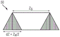
离子在漂移Z方向中以每次反射镜反射的平均距离ZR~C*sinα前进,其中C是离子反射点之间在X方向中的距离。离子轨迹15和16表示由离子源13中的初始离子包宽度ZS引起的离子轨迹的扩展。轨迹16和17表示离子包在其行进通过仪器时的角度发散,这在离子到达检测器14时将Z方向中的离子包宽度增大了量dZ。在离子包到达检测器14时离子包的总体扩展由ZD表示。The ions travel in the drift Z direction at an average distance Z R ~C*sinα per mirror reflection, where C is the distance in the X direction between ion reflection points. Ion trajectories 15 and 16 represent the expansion of the ion trajectories caused by the initial ion packet width Z S in
MR-TOF-MS 11在漂移Z方向中不提供离子聚焦,因此限制了离子束到达检测器14时在离子束在Z方向中过度分散之前可以执行的离子反射镜12之间的反射循环次数。因此,该布置需要每次反射的特定离子轨迹前进ZR,其必须高于特定值,以便避免离子轨迹由于离子分散而重叠并造成频谱混淆。MR-TOF-
如在WO 2014/074822(其通过引用并入本文)中所描述的,对于已知的正交离子加速器、径向阱和脉冲离子源,离子包的最低实际发散度预计为约+/-1mrad。实际离子源中离子的初始速度和空间扩展的组合限制了离子在最大能量扩展时的最小周转时间。为了使MR-TOF-MS仪器达到R=200000以上的质量分辨能力,通过仪器飞行时间区域的离子飞行路径必须延长到至少16m。因此,检测器14处的Z方向中的束宽度预计为ZD~30mm。进一步地,为了避免现有技术仪器11中相邻反射镜反射之间的离子轨迹和信号重叠,每次反射镜反射的离子轨迹前进ZR必须至少为50mm,以便超过在检测器处扩展的离子包ZD。相应地,Z方向中16次反射中的总前进(即源13和检测器14之间的距离)为ZA>800mm。当考虑Z边缘的边缘场、电极宽度、电隔离间隙和真空室宽度时,X-Z平面中的估计分析仪尺寸将大于1m×1m。这超出了商用仪器的实际尺寸,例如,因为真空室将太大并且不稳定。As described in WO 2014/074822 (which is incorporated herein by reference), for known orthogonal ion accelerators, radial traps and pulsed ion sources, the lowest practical divergence of ion packets is expected to be about +/- 1 mrad . The combination of initial velocity and spatial expansion of ions in practical ion sources limits the minimum turnaround time of ions at maximum energy expansion. In order for the MR-TOF-MS instrument to achieve mass resolution capabilities above R=200,000, the ion flight path through the instrument's time-of-flight region must be extended to at least 16 m. Therefore, the beam width in the Z direction at the
此类平面MR-TOF分析仪11的另一个问题是由于正交加速器13而导致的小占空比。例如,为了避免每次反射镜反射的离子轨迹前进值ZR=50mm和在检测器处的束宽度ZD=40mm的值的光谱重叠,每个注入的离子包的宽度被限制为约ZS=10mm。正交加速器的占空比可以估算为比率ZS/ZA,并且因此对于其中ZA>800mm的示例,正交加速器的占空比约为1%。当使用较小的分析仪时,占空比因此迅速变小,并且甚至下降至比该值更小。Another problem with such planar MR-
本发明的实施例提供具有改进的占空比、高分辨率和实用尺寸的平面MR-TOF-MS仪器。例如,在达到200,000以上的分辨率并且具有小于0.5m×1m的尺寸的同时,仪器可具有改进的占空比。Embodiments of the present invention provide planar MR-TOF-MS instruments with improved duty cycle, high resolution, and practical size. For example, the instrument can have an improved duty cycle while achieving resolutions above 200,000 and having dimensions of less than 0.5 m x 1 m.
发明人已经认识到,可以通过在X-Y平面中振荡离子来实质上改进平面MR-TOF-MS仪器,使得离子在离子反射镜12之间反射时不与源13(例如,正交加速器)碰撞。可替代地或另外地,离子可以在X-Y平面中振荡,使得离子不与接收器14(例如,检测器)碰撞,直到离子已经执行了至少预定数量的离子反射镜反射为止。因此,实施例涉及与图1所示和所述相似的仪器,不同之处在于离子在X-Y平面中振荡。The inventors have realized that a planar MR-TOF-MS instrument can be substantially improved by oscillating ions in the X-Y plane so that ions do not collide with source 13 (eg, an orthogonal accelerator) as they reflect between ion mirrors 12 . Alternatively or additionally, the ions may oscillate in the X-Y plane such that the ions do not collide with the receiver 14 (eg, detector) until the ions have performed at least a predetermined number of ion mirror reflections. Thus, the embodiments relate to an apparatus similar to that shown and described in Figure 1, except that the ions oscillate in the X-Y plane.
图2示出了说明根据本发明的实施例的多反射飞行时间质谱分析方法21的流程图。该方法包括以下步骤:(a)形成具有两个基本上平行对齐的静电场的离子反射镜,其中所述场在X-Y平面中可以是二维的并且基本上沿漂移Z方向延伸,并且其中所述场可以被布置用于X方向中的等时离子反射;(b)在离子源中形成脉冲离子包,并且在X-Z平面中以到X轴线的相对较小的倾斜角注入每个离子包,从而形成具有每次离子反射镜反射的前进距离ZR的平均锯齿形离子轨迹;(c)在从所述离子注入区域在Z方向中向下游移位的离子接收器上接收所述离子包;(d)提供所述离子包、所述离子源或所述离子接收器,以便以每次离子反射镜反射高于前进ZR的宽度拉伸;以及(e)在Y方向中移位或转向所述平均离子轨迹的至少一部分,以便在X-Y平面中形成周期性离子轨迹振荡,以便绕过用于至少一个离子反射镜反射的所述离子源或所述离子接收器。FIG. 2 shows a flow chart illustrating a
本发明的实施例的重要特征是通过使离子在X-Y平面中在分析仪内周期性地振荡以及在相对较小的离子注入角度α下在X-Z平面中的离子漂移而使离子绕过离子源13和/或离子检测器14。这将在下面更详细地描述。An important feature of embodiments of the present invention is that ions bypass the
图3A和图3B示出了用于离子反射镜之间的四次反射的分析仪的X-Y平面31中离子轨迹。在这些实施例中,离子源33和离子检测器34从装置的中心轴线在+Y方向中移位距离Y0。图3A示出了离子反射中的第一次(I)期间的离子轨迹,其中离子从离子源33脉冲进入上离子反射镜中,并且然后被反射回装置的中心轴线。图3A还示出了离子反射中的第二次(II)期间的离子轨迹,其中离子继续从装置的中心轴线行进到下离子反射镜中,并且然后在-Y方向中从中心轴线移位距离Y0的位置处被反射回中央Y-Z平面。图3B示出了离子反射中的第三次(III)期间的离子轨迹,其中离子继续行进返回到上离子反射镜中,并且然后在中心轴线上的位置处被反射回到中央Y-Z平面。图3B还示出了离子反射中的第四次(IV)期间的离子轨迹,其中离子继续从装置的中心轴线行进到下离子反射镜中,并且然后在+Y方向中从轴线移位距离Y0的位置处被反射回中央Y-Z平面,在此时离子冲击检测器34。3A and 3B show ion trajectories in the
平均离子轨迹针对C=1m的离子反射镜反射之间的距离(或镜盖之间的距离)与位移Y0=5mm被建模。为了更清楚地说明实施例,已经放大了Y方向中的离子轨迹。如图3A所示,平均离子轨迹的第一段(I)在Y0=5mm的Y位移处开始于中间平面X=0,并且离子首先平行于X轴(即角度γ=0)。然后离子进入上离子反射镜中,这引起离子在Y方向中振荡。在一次反射镜反射之后,离子返回到中心轴(X=0;Y=0),但处于γ=7mrad的角度。平均离子轨迹的第二段(II)继续,并且在反射镜反射之后返回到在-5mm的Y位移处并平行于X轴(γ=0)的X=0平面。如图3B所示,平均离子轨迹的第三段(III)继续,并且在反射镜反射之后,离子以γ=-7mrad的角度返回到中心轴线(X=0;Y=0)。平均离子轨迹的第四段(IV)继续并且在反射镜反射之后离子返回到X-Y平面中的原点(即,Y=5mm,γ=0),因此在四次反射镜反射之后闭合轨迹环。然而,应理解,在四次振荡期间离子继续在Z方向中移动。The average ion trajectory was modeled for the distance between ion mirror reflections (or distance between mirror caps) and displacement Y 0 =5 mm for C=1 m. Ion trajectories in the Y-direction have been exaggerated in order to illustrate the embodiments more clearly. As shown in Figure 3A, the first segment (I) of the average ion trajectory starts at mid-plane X= 0 at a Y displacement of Y0=5 mm, and the ions are first parallel to the X axis (ie angle γ=0). The ions then enter the upper ion mirror, which causes the ions to oscillate in the Y direction. After one mirror reflection, the ions return to the central axis (X=0; Y=0), but at an angle of γ=7 mrad. The second segment (II) of the averaged ion trajectory continues and after mirror reflection returns to the X=0 plane at a Y displacement of -5 mm and parallel to the X axis (γ=0). As shown in Figure 3B, the third segment (III) of the averaged ion trajectory continues, and after mirror reflection, the ions return to the central axis (X=0; Y=0) at an angle of γ=-7 mrad. The fourth segment (IV) of the averaged ion trajectory continues and after mirror reflections the ions return to the origin in the XY plane (ie, Y=5mm, γ=0), thus closing the trajectory loop after four mirror reflections. However, it should be understood that the ions continue to move in the Z direction during the four oscillations.
如下所述,分析仪静电场被假定为针对每个空间像差的最小时间进行了优化,使得重复轨迹回路停留在用于多次振荡的离子包的较小空间扩展处。As described below, the analyzer electrostatic field is assumed to be optimized for a minimum time per spatial aberration, so that the repeating trajectory loop stays at a small spatial expansion of the ion packet for multiple oscillations.
再次参考图3A和图3B,离子轨迹在Y方向中振荡,并且不会返回到它们的初始Y方向位移,直到每第四次离子反射镜反射。当离子源33位于初始Y方向位置中时,这确保对于每四次反射的前三次,离子不可能冲击离子源33(假设离子源和离子包与离子的初始Y0位移相比,在Y方向保持适中的宽度)。这意味着对于四次反射中的三次,离子能够在Z方向中沿装置漂移,而不处在其中它们可能冲击离子源33的Y位置处。因此,这使得离子源的长度能够在Z方向中延伸而不干扰前三次反射期间的离子轨迹。离子源33的长度可以延伸到4ZR的长度,即每次反射镜反射4次前进,因此增加了可注入在反射镜之间的离子的数量并且增强了仪器的占空比。在源33处的Z方向中的离子包的拉伸使得仪器对在源33和检测器34之间的Z方向中的离子包扩展较不敏感,因为此种扩展变得更小或者可与离子包的初始Z尺寸比较。离子包拉伸还减小分析仪中的空间电荷效应。它还允许使用更大面积的检测器34,从而延长了检测器34的动态范围和寿命。Referring again to Figures 3A and 3B, the ion trajectories oscillate in the Y direction and do not return to their initial Y direction displacement until every fourth ion mirror reflection. When the
可替代地,除了用于使得能够增大离子源长度的Y振荡之外,Y振荡可用于减小离子在每次离子反射镜反射行进的距离ZR,同时防止离子与离子源碰撞,从而减小仪器在Z方向中的尺寸。Alternatively, in addition to the Y-oscillation used to enable an increase in the length of the ion source, the Y-oscillation can be used to reduce the distance Z R that ions travel per ion mirror reflection, while preventing ions from colliding with the ion source, thereby reducing The size of the small instrument in the Z direction.
尽管已经描述了在Y方向中振荡离子的技术被用于防止离子在离子反射期间冲击离子源33,但是可替代地或另外地,该技术可以用于防止离子冲击检测器直到已经实现了期望数量的离子反射镜反射(在X方向中)为止。Although the technique of oscillating ions in the Y direction has been described as being used to prevent ions from impinging on
注意,用于在反射镜之间注入离子的不同的离子反射镜场和离子注入方案可以被用于形成环形X-Y振荡的不同图案,例如可以使用椭圆形轨迹或每个完整离子路径回路具有还更大次数的反射镜反射的图案。此外,Y振荡可由离子包角转向引起。Note that different ion mirror fields and ion implantation schemes for implanting ions between mirrors can be used to form different patterns of annular X-Y oscillations, for example elliptical trajectories can be used or each complete ion path loop has yet more A pattern of reflections from a large number of mirrors. In addition, Y oscillations can be caused by ion wrap angle steering.
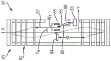
图4A至图4C示出了根据本发明的MR-TOF-MS仪器的实施例的三个不同视图。图4A示出了该实施例在X-Y平面中的视图,图4B示出了透视图,并且图4C示出了在Y-Z平面中的视图。实施例41是平面MR-TOR仪器,其包括两个平行的无网格离子反射镜42、离子源43(例如,脉冲离子源或正交离子加速器)、离子接收器44(例如检测器)、可选的挡块48和用于在Z方向中空间聚焦离子的可选透镜49。离子反射镜42基本上在漂移Z方向中延伸,因此在X-Y平面中从离子反射镜电极的Z边缘以足够的距离(约为离子反射镜窗的Y高度的两倍)形成二维静电场。离子源43和离子检测器44布置在通过分析仪的中间X-Z平面46的相对横向侧上,其中离子源43和检测器44中的每个从分析仪中间X-Z平面46移位距离Y0。在此实施例中,离子源43和离子检测器44二者在Y方向中都相对较窄。为了清楚起见,假设离子源43和检测器44中的每个的半宽度(W/2)小于Y0位移,离子源43在Y方向中是对称的,并且它从其中心发射离子包。Figures 4A to 4C show three different views of an embodiment of an MR-TOF-MS instrument according to the present invention. Figure 4A shows a view of this embodiment in the XY plane, Figure 4B shows a perspective view, and Figure 4C shows a view in the YZ plane.
本发明的实施例的重要特征是离子轨迹45在Y方向中移位,使得它们在沿着Z方向行进时绕过离子源43。如图4A所示,离轴平均离子轨迹45从Y0的Y方向中的位移开始,并且以参考图3A和图3B描述的方式进行。图4A将离子轨迹示出为两次反射镜反射的虚线,尽管可以在离子到达检测器之前执行两次以上的离子反射镜反射,如将参考图4B和图4C所描述的。An important feature of embodiments of the present invention is that the
所有视图都演示了离子轨迹45如何在X-Y平面中以与四次反射镜反射对应的周期振荡。轨迹45针对三次离子反射镜反射绕过离子源43,并在四次反射之后返回到相同的正Y位移。All views demonstrate how the
如图4B所示,离子以到X轴的倾斜角度α布置的轨迹45从离子源43被脉冲化。每个离子包因此对于每次离子反射镜反射在Z方向中前进距离ZR。离子包在不同时间的位置由不同组的白色圆圈47表示。可以看出,离子包开始于离子源43并被上离子反射镜42反射,使得当离子包到达中间Y-Z平面时,离子不在Y方向中移位。离子包然后继续进入下离子反射镜42并被反射,使得当离子包到达中间Y-Z平面时,离子被移位到Y方向中的位置-Y0。离子包然后第二次继续进入上离子反射镜42中并被反射,使得当离子包到达中间Y-Z平面时,离子不在Y方向上移位。离子包然后第二次继续进入下离子反射镜42中并被反射,使得当离子包到达中间Y-Z平面时,离子被移位到Y方向中的位置Y0。在此阶段,离子包在离子反射镜中执行四次反射,并且离子包具有与其原始在离子源43处相同的Y位移。As shown in FIG. 4B ,
离子包然后第三次继续进入上离子反射镜42中并被反射,使得当离子包到达中间Y-Z平面时,离子不在Y方向中移位。离子包然后第三次继续进入下离子反射镜42中并被反射,使得当离子包到达中间Y-Z平面时,离子被移位到Y方向中的位置-Y0。离子包然后第四次继续进入上离子反射镜42中并被反射,使得当离子包到达中间Y-Z平面时,离子不在Y方向中移位。离子包然后第四次继续进入下离子反射镜42中并被反射,使得当离子包到达中间Y-Z平面时,离子被移位到Y方向中的位置Y0。离子包然后第五次继续进入上离子反射镜42中并被反射,使得当离子包到达中间Y-Z平面时,离子不在Y方向中移位。离子包然后第五次继续进入下离子反射镜42中并被反射,使得当离子包到达中间Y-Z平面时,离子被移位到Y方向中的位置-Y0,在该位置-Y0它们冲击检测器44。The ion packets then proceed a third time into the
如上所述,图4C示出了Y-Z平面中的实施例的视图。图4C中还示出了由图4B中的白色圆圈示出的不同时间的离子包的位置。如图4C所示,在离子反射镜中每次反射之后在Z方向中的离子位移为ZR。可以看出,在第一次离子反射镜反射之后,离子包仅行进了Z方向的距离ZR,小于离子源43在Z方向中的长度。如果离子相对于其初始位置在Y方向中未被移位,则在第一次离子反射镜反射之后,离子包的尾部(在Z方向中)将冲击离子源43。然而,当离子已经相对于它们在离子源43处的初始位置在Y方向中移动时,它们能够绕过离子源43并且继续通过该装置。第二次离子反射和第三次离子反射也引起离子包具有Y方向位置,使得它们不可能冲击检测器。仅在第四次离子反射镜反射之后,离子包已经返回到其原始的Y方向位置,即离子源43的位置。然而,在这个阶段,离子已经在Z方向中行进了距离4ZR,此时离子包在Z方向中行进得足够远,使得离子不可能冲击离子源43。As mentioned above, Figure 4C shows a view of the embodiment in the YZ plane. Also shown in Fig. 4C are the positions of the ion packets at different times shown by the white circles in Fig. 4B. As shown in Figure 4C, the ion displacement in the Z direction after each reflection in the ion mirror is ZR. It can be seen that after the first ion mirror reflection, the ion packets have only traveled a distance Z R in the Z direction, which is less than the length of the
该技术允许其中离子源43在Z方向中的长度(即,初始离子包47在Z方向中的长度)可以高达大约4ZR,而不会在离子行进通过装置时有离子撞击离子源43。因此,在Y方向中振荡离子包允许离子源43在Z方向中的长度增大,或者相对于离子不在Y方向中振荡的布置,在每次反射之后离子行进的Z距离ZR减小。增大离子源43的长度或减小长度ZR具有上述优点。This technique allows where the length of the
以与上述类似的方式,可以针对每四次反射中的三次,使离子包47绕过“窄”离子检测器44。换句话说,检测器44可以位于Y方向中,使得由于离子在Y方向中的位置,离子不可能针对四次反射中的三次冲击检测器44。这允许检测器44在Z方向中的长度相对于其中离子不在Y方向中振荡的布置而增大。In a similar manner to that described above, the
由于离子包在电场中的初始角度发散和不精确性,离子包在其行进通过装置时可在Z方向中扩张。为了避免这造成光谱混淆,可以设置挡块48,用于在离子包行进通过装置时阻挡布置在离子包的Z方向边缘处的离子的通过。因此,在Z方向中发散不期望的量的离子包中的任何离子可能会冲击挡块48,并因此被挡块48阻挡并且被阻止到达检测器44。Due to the initial angular divergence and inaccuracies of the ion packets in the electric field, the ion packets may expand in the Z-direction as they travel through the device. To avoid spectral confusion caused by this, a
重要的是要注意,与图1所示的现有技术平面MR-TOF-MS仪器11相比,Z方向中的离子包扩展较不重要。在现有技术MR-TOF-MS仪器11中,离子包宽度ZS和包Z扩展dZ二者都必须远小于在每次反射期间在Z方向中行进的距离ZR。相反,本发明的实施例41允许使用长得多的离子源43和检测器44,其中离子源的长度ZS和检测器的长度ZD高达约4ZR。因此,与离子源和检测器长度相比(dZ<ZS~ZD<4ZR),保持离子包扩展dZ相对较短是相对容易的。因此离子挡块48上的离子损失可保持适中。It is important to note that ion packet expansion in the Z direction is less important than the prior art planar MR-TOF-
可选地,离子挡块48中的至少一个可以被用作辅助离子检测器,例如以感测行进通过该装置的离子包的总体强度。例如,这可以被用于调节主检测器44的增益。例如,来自辅助检测器的离子信号可以被馈送到控制系统中,该控制系统基于离子信号的大小控制主检测器44的增益水平。如果来自辅助检测器的离子信号相对较低,则控制系统将主检测器44的增益设定得相对较高,反之亦然。可替代地,来自辅助检测器的离子信号可以被馈送到控制系统中,该控制系统控制离子注入到反射镜之间的空间中的角度,或者控制当离子在反射镜之间行进时改变离子的离子轨迹的转向系统。例如,这可以通过控制系统基于来自辅助检测器的离子信号控制施加到电极的电压的大小而实现。这些后面的方法改变在反射镜之间移动的离子的轨迹,并且控制系统可以使用于自辅助检测器的反馈以确保离子轨迹沿着期望的轨迹。例如,控制系统可以控制离子轨迹直到辅助离子检测器输出其最小离子信号为止,指示大部分离子在反射镜之间传输,而不是冲击辅助检测器。Optionally, at least one of the ion blocks 48 may be used as an auxiliary ion detector, eg, to sense the overall intensity of ion packets traveling through the device. This can be used to adjust the gain of the
假设离子包经历16次离子反射镜反射,具有到达检测器44时的30mm的Z方向中的扩展dZ,ZR为20mm,并且ZS=ZD=60mm,则这个实施例的MR-TOF仪器将具有仅ZA=320mm的Z方向中的长度和仅20%的挡块48上的离子损失(如图4D所示)。这将与上面关于图1所述的对应的现有技术的示例进行比较,其具有ZA=800mm的Z方向中的长度。Assuming that the ion packet undergoes 16 ion mirror reflections, has an extension dZ in the Z direction of 30 mm when it reaches the
因此,将离子布置成在Y方向中振荡允许离子包绕过离子源43和离子检测器44以进行多次离子反射,并因此允许离子包、离子源43和离子检测器44在漂移Z方向中扩展。Thus, arranging the ions to oscillate in the Y direction allows the ion packets to bypass the
在上述离子反射镜场的特定示例中,Y方向振荡回路在四次离子反射镜反射中闭合。然而,可以设想,Y方向振荡回路可以在更少或更多次数的离子反射镜反射中闭合。In the specific example of the ion mirror field described above, the Y-direction oscillatory loop is closed in four ion mirror reflections. However, it is envisaged that the Y-direction oscillatory loop can be closed in fewer or more ion mirror reflections.
与现有技术的平面MR-TOF-MS仪器11相比,上述实施例的技术提供了多种改进。例如,实施例在分析仪Z方向长度中提供显著的减小(至少两倍)。这使得在具有实际尺寸的仪器中能够提供R~200,000分辨率所需的16m的离子路径长度。该实施例提供了显著的离子源拉伸(5倍至10倍),从而改进脉冲离子转换器的占空比,其取决于转换器类型估计低于5%至20%。该实施例使得离子包能够在Z方向中被拉伸到30mm至100mm,这扩展了分析仪的空间电荷极限。该实施例使检测器能够被拉伸到30mm至100mm,这延长了检测器的动态范围和使用寿命。The techniques of the above-described embodiments provide various improvements over the prior art planar MR-TOF-
在X-Y平面中振荡离子的方法引起关注,离子的Y方向位移可能导致离子包的空间或飞行时间扩展,这可能限制具有高阶像差的分析仪的分辨率。在所附的模拟中解决了这个关注,示出分析仪的几何结构能够在Y轴振荡的情况下操作以用于真实的离子包。Methods of oscillating ions in the X-Y plane are of concern, and Y-direction displacement of ions can lead to spatial or time-of-flight expansion of ion packets, which can limit the resolution of analyzers with higher-order aberrations. This concern is addressed in the accompanying simulations showing that the analyzer geometry is able to operate with Y-axis oscillations for real ion packets.
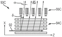
图5A示出了在X-Z平面中根据本发明的实施例的平面MR-TOF-MS仪器51的几何结构,并且图5B示出了X-Y平面中该实施例的离子反射镜中的一个以及可适用于仪器的部件的各种电压和尺度。在所建模的实施例中,离子反射镜52中的静电势的轴向分布提供了在6keV的反射镜之间的漂移空间中的平均离子动能。反射镜有四个独立调谐的电极;其中三个(帽电极和两个相邻的电极)可以被设定为延迟电压,并且另一个(图5B中最长)被设定为加速电压。相对离子反射镜之间的总帽到帽距离C大约为1米,并且每个反射镜内窗口的Y高度可以为39mm。X-Z平面中的离子注入角度α被设定为20mrad,离子轨迹的初始Y位移是Y0=5mm,并且检测器被设置在-Y0=5mm的Y位移。Figure 5A shows the geometry of a planar MR-TOF-
图5A示出了光亮和黑暗的模拟离子轨迹。光亮离子轨迹表示从离子源后方(在Z方向中)发射的离子,而黑暗离子轨迹表示从离子源前方(在Z方向中)发射的离子。在Y方向中振荡离子的技术允许离子源和离子检测器二者在Z方向中都具有大约50mm的长度(例如,源长度为50mm,并且检测器长度为56mm)。由于离子源在Z方向中具有50mm的长度,所以光亮和黑暗的模拟轨迹在Z方向中偏移了几乎50mm。在16次离子反射镜反射期间在Z方向中行进的总平均距离直到离子撞击检测器为止是ZA=280mm。考虑到平面离子反射镜的Z-边缘场,这提供了在Z方向中的整个离子反射镜长度需要大约为420mm,其对于商业仪器来说是合理的。Figure 5A shows simulated ion trajectories for light and dark. Bright ion trajectories represent ions emitted from behind the ion source (in the Z direction), while dark ion trajectories represent ions emitted from the front of the ion source (in the Z direction). The technique of oscillating the ions in the Y-direction allows both the ion source and the ion detector to have a length of approximately 50 mm in the Z-direction (eg, a source length of 50 mm and a detector length of 56 mm). Since the ion source has a length of 50 mm in the Z direction, the simulated trajectories of light and dark are offset in the Z direction by almost 50 mm. The total average distance traveled in the Z direction during 16 ion mirror reflections until the ions hit the detector is Z A =280 mm. Considering the Z-fringe field of the planar ion mirror, this provides that the overall ion mirror length in the Z direction needs to be approximately 420 mm, which is reasonable for commercial instrumentation.
图5C至图5E示出了分析仪中的示例离子轨迹的X-Y平面中的投影(Y标度被放大),其被优化用于相对于空间和能量扩展减小飞行时间像差。Figures 5C-5E show projections in the X-Y plane of example ion trajectories in the analyzer (Y scale magnified) optimized to reduce time-of-flight aberrations relative to spatial and energy spread.
图5C示出具有不同离子能量的离子轨迹。可以对离子反射镜进行调谐,以便在每次反射之后消除分析仪中间的空间能量分散,并且从而在每两次反射之后提供空间消色差(即,不存在坐标和角度能量分散)。根据一般的离子光学理论(M.Yavor,带电粒子分析仪的光学器件(Optics of Charged Particle Analyzers),学术出版社(Acad.Press),阿姆斯特丹,(Amsterdam),2009),此种调谐提供了关于空间离子扩展的一阶等时性离子传送(即dt/dY=Dt/dB=0,其中B=dY/dX是离子轨迹的倾斜角)。Figure 5C shows ion trajectories with different ion energies. The ion mirror can be tuned to eliminate spatial energy dispersion among the analyzers after each reflection, and thus to provide spatial achromatic (ie, no coordinate and angular energy dispersion) after each reflection. According to general ion optics theory (M. Yavor, Optics of Charged Particle Analyzers, Acad. Press, Amsterdam, 2009), this tuning provides information about First-order isochronous ion transport for spatial ion spreading (ie, dt/dY=Dt/dB=0, where B=dY/dX is the tilt angle of the ion trajectory).
图5D示出具有不同的初始Y坐标的离子轨迹。可以对离子反射镜进行调谐,以便在一次反射之后在分析仪的中间提供离子轨迹的平行到点聚焦,并且因此在每两次反射之后提供平行到平行聚焦。Figure 5D shows ion trajectories with different initial Y coordinates. The ion mirror can be tuned to provide parallel-to-spot focusing of the ion trajectory in the middle of the analyzer after one reflection, and therefore parallel-to-parallel focusing after every two reflections.
图5E示出具有离子轨迹的不同初始B角的离子轨迹。可以对离子反射镜进行调谐,以便在一次反射之后在分析仪的中间提供离子轨迹的点到平行聚焦,并且因此在每两次反射之后提供点到点聚焦,并且在每四次反射之后进行统一变换。总的来说,在每四次反射之后,离子包的空间相位空间经历统一变换。根据一般的离子光学理论(D.C.Carey,核仪器方法(Nucl.Instrum.Meth.),v.189(1981)365页),离子反射镜的调谐仅满足一个附加条件d2Y/dBdK=0,其中K是离子动能,导致消除由于空间(坐标和角度)变化引起的所有二阶飞行时间像差,以及16,20,24...等次数的反射后的混合空间和能量变化。飞行时间相对于能量扩展的剩余依赖性可以通过适当选择电极长度和帽到帽距离以消除到至少三阶像差(dT/dK=d2T/dK2=d3T/dK3=0)。Figure 5E shows ion trajectories with different initial B angles of the ion trajectories. The ion mirror can be tuned to provide point-to-parallel focusing of the ion trajectory in the middle of the analyzer after one reflection, and thus point-to-point focusing after every two reflections, and unification after every fourth reflection transform. Overall, after every fourth reflection, the spatial phase space of the ion packets undergoes a uniform transformation. According to general ion optics theory (DCCarey, Nucl. Instrum. Meth., v. 189 (1981) p. 365), the tuning of the ion mirror only satisfies one additional condition d 2 Y/dBdK=0, where K is the ion kinetic energy, resulting in the cancellation of all second-order time-of-flight aberrations due to spatial (coordinate and angle) changes, as well as mixed spatial and energy changes after 16, 20, 24, etc. reflections. The remaining dependence of time-of-flight on energy spread can be eliminated to at least third order aberrations (dT/dK=d2T/ dK2 = d3T / dK3 =0) by appropriate selection of electrode length and cap-to-cap distance .
图6A至图6C示出了对于具有1.2度的角发散度和18eV的束能量的1.4mm直径的连续离子束的由具有300V/mm的加速场的50mm长的正交加速器产生的离子包的情况,对图5A至图5B所示分析仪的离子光学模拟结果。示出了在检测器处得到的离子峰值时间宽度以及时间-能量图,并且表征为对于1000a.m.u.的离子质量在约488μs的飞行时间处的FWHM为1.1ns,即质量分辨能力为224,000。Figures 6A-6C show the ion packets generated by a 50 mm long orthogonal accelerator with an acceleration field of 300 V/mm for a 1.4 mm diameter continuous ion beam with an angular divergence of 1.2 degrees and a beam energy of 18 eV case, ion optics simulation results for the analyzer shown in Figures 5A-5B. The ion peak time width and time-energy plot obtained at the detector are shown and characterized as a FWHM of 1.1 ns at a time-of-flight of about 488 μs for an ion mass of 1000 a.m.u., ie a mass resolving power of 224,000.
应该理解的是,当在制作窄的离子源或窄的检测器处遇到挑战时,其它数字折衷方案可用于在较小的Y位移处改进分辨率或针对较大的Y位移在某种程度上折衷的分辨率。It should be understood that when challenges are encountered at making narrow ion sources or narrow detectors, other digital tradeoffs can be used to improve resolution at smaller Y-shifts or to some extent for larger Y-shifts compromise resolution.
由于MR-TOF仪器像差通常随着振荡期间离子的Y位移的幅度而增长,所以期望最小化轨迹Y偏移Y0。另一方面,最小的Y偏移应仍然足以区分由离子包Y宽度和Y偏差限定的轴向轨迹和Y位移离子轨迹。此外,在振荡中的至少一些(例如,三个Y方向振荡)期间,最小的Y偏移必须足以绕过离子源和/或检测器。换句话说,取决于离子注入方案,最小的Y偏移可以取决于离子源和/或检测器的物理宽度。为了在使离子包绕过离子源的同时保持离子包的适度的Y位移,根据本发明可以使用多种方法。例如,离子源可以是窄的,例如离子源可以是具有由电阻板形成的DC加速器的正交加速器(OA)。可替代地,可以经由在X-Y平面中具有曲率的弯曲等时扇形区接口注入离子包。可替代地或另外地,可以采用脉冲偏转器,其偏转Y方向中的离子,以便与正交加速器的宽度的一半相比减小离子包的位移。Since MR-TOF instrumental aberrations typically grow with the magnitude of the ion's Y displacement during oscillation, it is desirable to minimize the trajectory Y shift Y 0 . On the other hand, the smallest Y offset should still be sufficient to distinguish axial and Y-shifted ion trajectories defined by the ion packet Y width and Y offset. Furthermore, during at least some of the oscillations (eg, three Y-direction oscillations), a minimum Y offset must be sufficient to bypass the ion source and/or detector. In other words, depending on the ion implantation scheme, the minimum Y offset may depend on the physical width of the ion source and/or detector. In order to maintain a modest Y-shift of ion packets while bypassing the ion source, various methods can be used in accordance with the present invention. For example, the ion source may be narrow, eg, the ion source may be an orthogonal accelerator (OA) with a DC accelerator formed by resistive plates. Alternatively, ion packets can be implanted via a curved isochronous sector interface with curvature in the XY plane. Alternatively or additionally, a pulsed deflector may be employed which deflects ions in the Y direction so as to reduce the displacement of the ion packets compared to half the width of the orthogonal accelerator.
为了避免检测器干扰绕开的离子轨迹,检测器可以包括离子到电子转换器,其可以具有比标准TOF检测器更小的边沿尺寸。检测器产生的二次电子可以通过非均匀磁场或静电场聚焦(对于快速检测器中的较小点)或者散焦到检测器(用于较长检测器寿命)上。To avoid detector interference with bypassed ion trajectories, the detector may include an ion-to-electron converter, which may have smaller edge dimensions than standard TOF detectors. Secondary electrons generated by the detector can be focused (for smaller spots in fast detectors) or defocused onto the detector (for longer detector lifetime) by a non-uniform magnetic or electrostatic field.
图7A和图7B示出了与图4A至图4D所示相同的MR-TOF-MS仪器的实施例,不同之处在于等时静电扇形区75用于注入离子到飞行时间区域和从飞行时间区域提取离子。图7A示出了X-Y平面中的视图,并且图7B示出了Y-Z平面中的视图。仪器71包括平面MR-TOF分析仪72,其包括布置在飞行时间区域之外的宽度S的相对较宽的离子源73、布置在飞行时间区域之外的宽度D的相对较宽的离子检测器74,以及用于将离子源73和离子检测器74与飞行时间区域接合的宽度W的等时静电扇形区75。扇形区75的弯曲的离子轨迹78位于分析仪72的X-Y平面内。Figures 7A and 7B show the same embodiment of the MR-TOF-MS instrument as shown in Figures 4A-4D, except that the isochronous
在操作中,离子包76从离子源73加速进入入口扇形区75中。入口扇形区75沿着弯曲的离子轨迹78将来自离子源73的离子包76转移到分析仪72中,以便在距X-Z中间平面的Y位移Y0处将离子分析仪内的轨迹77平行于Y轴布置。这种布置使得能够将离子注入到具有Y位移Y0的分析仪72中,该Y位移Y0比通过在分析仪的飞行区域中布置离子源所提供的Y位移更容易控制(例如,如图4A至图4B)。例如,当在Y方向中使用具有相对较宽的宽度的离子源时,可能难以将离子源布置在分析仪的飞行区域内,使得离子具有期望的初始Y0位移并且使得离子当它们沿着装置行进时不会冲击离子源。例如,在图4A至图4B所示的实施例中,从离子源的中心(在Y方向中)发射离子,并且因此不能使初始位移Y0小于离子源的半宽度(在Y方向中),而离子随后不冲击离子源。相反,从图7A至图7B可以看出,使用扇形区78使得初始位移Y0能够明显小于离子源的半宽度S/2和检测器的半宽度D/2。In operation,
为了避免离子冲击扇形区75,扇形区中每个扇形区的Y方向中的半宽度(W/2)被布置成小于Y0。In order to avoid ions impacting the
扇形区接口75的等时特性已经在通过引用并入本文的WO 2006/102430中描述。使用扇形区接口75使得Y0轨迹位移的幅度与离子源73的物理宽度S或检测器74的物理宽度D在中等时间分散处解耦。The isochronous properties of the
图7B对应于图4C,不同之处在于等时静电扇形区75用于注入离子到飞行时间区域和从飞行时间区域提取离子。图7B示出了离子源73、离子接收器74和弯曲扇形区75的投影。圆圈组47表示在不同时间穿过Y-Z中间平面的离子包的不同位置。如前所述,可提供离子挡块48以移除过度发散的离子包的部分。而且,如前所述,挡块48中的一个或多个可以是用于优化通过分析仪72的离子束传输的辅助检测器,或者是用于主检测器74的自动增益调节的辅助检测器。Figure 7B corresponds to Figure 4C except that isochronous
图8A至图8B示出了与图4A至图4D所示相同的MR-TOF-MS仪器的实施例,不同之处在于离子偏转器用于沿着期望的轨迹注入离子。图8A示出了X-Y平面中的视图,并且图8B示出了Y-Z平面中的视图。Figures 8A-8B show an embodiment of the same MR-TOF-MS instrument as shown in Figures 4A-4D, except that an ion deflector is used to implant ions along a desired trajectory. Figure 8A shows a view in the X-Y plane, and Figure 8B shows a view in the Y-Z plane.
仪器81包括平面MR-TOF分析仪82,其包括宽度S(S>2Y0)的相对较宽的离子源83、宽度D(D<2Y0)的相对较窄的检测器84、宽度W1的偏转器85和可选的偏转器88。如在前面的实施例中那样,期望注入离子,使得它们首先在距X轴Y0的位移处平行于X轴移动。如前所述,如果源83在Y方向中的宽度大于2Y0,则当离子行进通过该装置时,离子将冲击离子源83。离子源83因此在Y方向中偏移,以便避免在离子反射镜反射之后干扰离子轨迹87。离子然后可以从离子源83朝向Y=0平面导引,并且偏转器85可以用于偏转离子轨迹,使得偏转器85沿着轨迹87平行于X轴并且在Y0的偏移处转向离子包。
离子源83的离子喷射轴可以被布置成平行于X轴,并且可以提供另外的离子偏转器88以将离子包沿着轨迹86朝向偏转器85转向,使得离子的Y位移在偏转器85的中心处变成等于Y0。偏转器85然后沿着轨迹86将包转向。可替代地,离子源83的喷射轴可以在X-Y平面中倾斜,以便沿着轨迹89朝向偏转器85喷射离子包,使得离子的Y位移在偏转器85的中心处变成等于Y0。偏转器85然后沿着轨迹87将包转向。偏转器85和/或88可以是脉冲或静态偏转器。The ion ejection axis of the
脉冲或静态偏转器的多种其它布置能够沿着移位的轨迹87转移离子包,同时避免它们干扰具有高于2Y0的Y方向宽度S的中等宽度的离子源。Various other arrangements of pulsed or static deflectors can divert ion packets along displaced
图8C示出了与图8A至图8B所示相同的替代实施例的Y-Z平面中的视图。不同之处在于偏转器85被替换为在Y方向中具有较大宽度的偏转器90。偏转器90具有与偏转器85相同的功能,不同之处在于偏转器90的宽度W2被选择为高于2Y0,由此提供避免其干扰分析仪82内的离子轨迹87的替代方式。换句话说,偏转器包括在Y方向中彼此相对的电极,其中电极被布置在Y=0平面的相对侧上,并且其中每个电极距Y=0平面的距离大于Y0。偏转器90以脉冲方式操作以便避免在第一次离子反射镜反射之后的离子包失真。Figure 8C shows a view in the YZ plane of the same alternative embodiment as shown in Figures 8A-8B. The difference is that the
图9A至图9B示出了与图4A至图4D所示相同的MR-TOF-MS仪器的实施例,不同之处在于离子源可以是周期性地将连续束92或脉冲离子束脉冲到离子反射镜中的脉冲转换器93。例如,脉冲转换器93可以是正交加速装置。图9A示出了X-Y平面中的视图,并且图9B示出了Y-Z平面中的视图。如同在前述实施例中的离子源一样,脉冲转换器93可以基本上沿着漂移Z方向取向,其中转换器长度ZS延伸到高达4*ZR。转换器93可以是无栅格的并且可以具有用于在Y方向中提供几个mrad的低发散度的终止静电透镜。Figures 9A-9B show an embodiment of the same MR-TOF-MS instrument as shown in Figures 4A-4D, except that the ion source may be a
由脉冲转换器93产生的离子包以到X轴的小倾斜角α被注入到飞行时间区域中。期望优化角度α,使得可以在多组的四次反射之间分离离子轨迹,同时保持分析仪在Z方向中的合理长度,例如ZA~300mm至400mm。离子轨迹45的角度α可以被优化为~20mrad。脉冲转换器不一定提供离子轨迹的最佳倾斜角,并且电极可以被提供以转向离子包以便实现最佳倾斜角α~20mrad。The ion packets generated by the
图9C示出了包括用于直通模式的径向喷射离子阱的脉冲转换器93A的X-Y平面中的视图和X-Z平面中的视图。如X-Y视图所示,脉冲转换器93包括具有顶部和底部电极以及侧阱电极的直通式直线离子阱。将射频电压信号施加到侧阱电极以便限制离子束92。离子束可以是具有能量KZ=3eV至5eV的相对较慢的离子束。周期性地,RF信号被关断,并且电压脉冲被施加到顶部电极和底部电极,以便通过顶部电极中的狭缝提取离子包。每个离子包在DC加速级94A内被加速到例如KX=5keV至10keV的能量。离子包具有自然倾斜角

由于离子束92具有减小的能量(与正交加速度相比),所以脉冲转换器93A提供改进的占空比,但是由于离子包在Z方向中扩张,可能发生挡块48上的附加离子损失。现在将描述数字示例。我们假设连续离子束92的平均离子能量KZ=5eV,Z方向中的能量扩展为ΔKZ=1eV,并且直线阱的长度Zs=80mm(使用如图4的符号)。我们还假设MR-TOF分析仪的加速能量KX=8000eV,并且在检测到离子之前执行16次离子反射镜反射。在这种情况下,平均倾斜角为


图9D示出了包括在累积模式中使用的径向喷射离子阱的脉冲转换器93B的X-Y平面中的视图和X-Z平面中的视图。如X-Y视图所示,脉冲转换器93包括具有顶部和底部电极以及侧阱电极的直通式直线离子阱。将射频电压信号施加到侧阱电极以便将脉冲注入的离子束96限制在径向方向中。该阱包括RF阱的若干个段(在示意图中未示出),并且将电压施加到这些段以便在阱的Z方向中提供~1V的DC井。在气体碰撞中,注入的离子在时间T和气体压力P下被捕获并被抑制,其中P*T的乘积可以是大约3ms*mTor至5ms*mTor。典型的压力P可以是2mTor至3mTor,并且典型的时间T可以是1ms至2ms。周期性地,RF信号被关断,并且电脉冲被施加到顶部和底部电极,以便通过顶部电极中的狭缝提取离子包。离子包可以在DC加速级94A内以零的自然倾斜角
阱93B的长度ZS与转向角α/2的乘积应当在500mm*mrad以下,以在与MRTOF分析仪的能量容限ΔKX/KX=6%相匹配的离子包的相对能量扩展下在1ns的FWHM下维持T|ZK时间像差。因此,阱长度ZS可以以α/2=10mrad的角度保持在50mm处。The product of the length Z S of the
尽管累积阱转换器提供了统一占空比,但是阱可快速溢出,因为当使用具有每秒1E+9到1E+10个离子的产率的实际现代离子源时,在1ms累积周期期间1E+6个离子的离子云可以被累积。这个问题可以通过使用受控或交替的离子注入时间部分解决。具有长度ZS~50mm的拉伸离子阱93B仍然提供比具有1mm特性离子云尺寸的现有技术轴向喷射阱大得多的空间电荷容量。Although the accumulator trap converter provides a uniform duty cycle, the trap can overflow quickly because when using a practical modern ion source with a yield of 1E+9 to 1E+10 ions per second, 1E+ during a 1 ms accumulation period An ion cloud of 6 ions can be accumulated. This problem can be partially solved by using controlled or alternating ion implantation times. The stretched
图9E示出脉冲转换器93C,其包括具有与Z轴对齐的DC加速级94C和多偏转器95C的传统正交加速器。多偏转器95C包括由薄(例如,0.1mm以下)且紧密摆放的偏转板形成的多个偏转单元,其可选地布置在双面印刷电路板上。可选地,每个偏转单元的Z宽度大约为ZC=1mm。已知正交加速操作在离子束92能量高于15eV至20eV时稳定。离子束92可以被设定为具有KZ=20eV的能量,产生KX=8keV的具有倾斜角


图9F示出脉冲转换器93D,其包括到Z轴以β~30mrad的角度倾斜的传统正交加速器94D和分段偏转器95D。偏转器95D的若干段被布置成在偏转器的中等Y宽度处提供均匀的偏转场。安全的离子束能量被选择为大约15eV至20eV,引起自然倾斜角为

图10是与图4C所示实施例相同的实施例的Y-Z平面中的视图,不同之处在于检测器44被布置成使得离子仅在四次离子反射镜反射之后冲击检测器44。这种布置提供了中等分辨率的相对较高的占空比。举例来说,在这种布置中,帽到帽间距可以是C=1m,并且有效飞行路径可以是4m(其为Xevo XS的当前Q-TOF中的有效飞行路径的1.6倍大)。如果离子束在推动器中在推动方向中具有1.2mm至1.4mm的物理范围,并且推动器中的梯度为300V/mm,则对于单电荷离子,由离子看到的能量扩展Δk大约为420eV。此种装置的能量接受率由Δk/k给出,其中k是加速电压(例如6000V)。这使得能量接受率为6%至7%,同时保持RA=100K。因此,1.2mm至1.4mm的束可以以300V/mm的推动器梯度使用。Figure 10 is a view in the Y-Z plane of the same embodiment as shown in Figure 4C, except that the
与现有技术MR-TOF-MS仪器中的5mm至6mm的长度相比,本发明允许离子加速器在Z方向中的显著拉伸,例如到30mm至80mm。因此,本发明显著改进了具有正交加速器的仪器的质量范围和灵敏度。The present invention allows significant stretching of the ion accelerator in the Z direction, eg to 30mm to 80mm, compared to lengths of 5mm to 6mm in prior art MR-TOF-MS instruments. Thus, the present invention significantly improves the mass range and sensitivity of instruments with orthogonal accelerators.
尽管已经参考各种实施例描述了本发明,但是本领域技术人员将理解,可以在形式和细节上进行各种改变而不脱离如所附权利要求书中阐述的本发明的范围。Although the present invention has been described with reference to various embodiments, it will be understood by those skilled in the art that various changes in form and details may be made therein without departing from the scope of the invention as set forth in the appended claims.
Claims (29)
Applications Claiming Priority (3)
| Application Number | Priority Date | Filing Date | Title |
|---|---|---|---|
| GB1507363.8 | 2015-04-30 | ||
| GBGB1507363.8A GB201507363D0 (en) | 2015-04-30 | 2015-04-30 | Multi-reflecting TOF mass spectrometer |
| PCT/GB2016/051238 WO2016174462A1 (en) | 2015-04-30 | 2016-04-29 | Multi-reflecting tof mass spectrometer |
Publications (2)
| Publication Number | Publication Date |
|---|---|
| CN107851549A CN107851549A (en) | 2018-03-27 |
| CN107851549B true CN107851549B (en) | 2020-09-11 |
Family
ID=53488902
Family Applications (1)
| Application Number | Title | Priority Date | Filing Date |
|---|---|---|---|
| CN201680034050.9A Active CN107851549B (en) | 2015-04-30 | 2016-04-29 | Multi-reflection TOF mass spectrometer |
Country Status (6)
| Country | Link |
|---|---|
| US (1) | US10741376B2 (en) |
| EP (1) | EP3289602B1 (en) |
| JP (1) | JP6596103B2 (en) |
| CN (1) | CN107851549B (en) |
| GB (2) | GB201507363D0 (en) |
| WO (1) | WO2016174462A1 (en) |
Families Citing this family (31)
| Publication number | Priority date | Publication date | Assignee | Title |
|---|---|---|---|---|
| GB2476964A (en) * | 2010-01-15 | 2011-07-20 | Anatoly Verenchikov | Electrostatic trap mass spectrometer |
| GB201507363D0 (en) | 2015-04-30 | 2015-06-17 | Micromass Uk Ltd And Leco Corp | Multi-reflecting TOF mass spectrometer |
| GB201520134D0 (en) | 2015-11-16 | 2015-12-30 | Micromass Uk Ltd And Leco Corp | Imaging mass spectrometer |
| GB201520130D0 (en) | 2015-11-16 | 2015-12-30 | Micromass Uk Ltd And Leco Corp | Imaging mass spectrometer |
| GB201520540D0 (en) | 2015-11-23 | 2016-01-06 | Micromass Uk Ltd And Leco Corp | Improved ion mirror and ion-optical lens for imaging |
| GB201613988D0 (en) | 2016-08-16 | 2016-09-28 | Micromass Uk Ltd And Leco Corp | Mass analyser having extended flight path |
| JP6859450B2 (en) * | 2017-03-27 | 2021-04-14 | レコ コーポレイションLeco Corporation | Multiple reflection time-of-flight mass spectrometer and mass spectroscopic analysis method |
| GB2567794B (en) * | 2017-05-05 | 2023-03-08 | Micromass Ltd | Multi-reflecting time-of-flight mass spectrometers |
| GB2612703B (en) * | 2017-05-05 | 2023-08-09 | Micromass Ltd | Multi-reflecting Time-of-Flight mass spectrometers |
| GB2563571B (en) | 2017-05-26 | 2023-05-24 | Micromass Ltd | Time of flight mass analyser with spatial focussing |
| US11049712B2 (en) | 2017-08-06 | 2021-06-29 | Micromass Uk Limited | Fields for multi-reflecting TOF MS |
| US11295944B2 (en) | 2017-08-06 | 2022-04-05 | Micromass Uk Limited | Printed circuit ion mirror with compensation |
| US11081332B2 (en) | 2017-08-06 | 2021-08-03 | Micromass Uk Limited | Ion guide within pulsed converters |
| CN111164731B (en) | 2017-08-06 | 2022-11-18 | 英国质谱公司 | Ion implantation into a multichannel mass spectrometer |
| US11239067B2 (en) | 2017-08-06 | 2022-02-01 | Micromass Uk Limited | Ion mirror for multi-reflecting mass spectrometers |
| WO2019030477A1 (en) * | 2017-08-06 | 2019-02-14 | Anatoly Verenchikov | Accelerator for multi-pass mass spectrometers |
| WO2019030475A1 (en) | 2017-08-06 | 2019-02-14 | Anatoly Verenchikov | Multi-pass mass spectrometer |
| GB201806507D0 (en) | 2018-04-20 | 2018-06-06 | Verenchikov Anatoly | Gridless ion mirrors with smooth fields |
| GB201807605D0 (en) | 2018-05-10 | 2018-06-27 | Micromass Ltd | Multi-reflecting time of flight mass analyser |
| GB201807626D0 (en) | 2018-05-10 | 2018-06-27 | Micromass Ltd | Multi-reflecting time of flight mass analyser |
| GB201808530D0 (en) | 2018-05-24 | 2018-07-11 | Verenchikov Anatoly | TOF MS detection system with improved dynamic range |
| GB201810573D0 (en) * | 2018-06-28 | 2018-08-15 | Verenchikov Anatoly | Multi-pass mass spectrometer with improved duty cycle |
| GB2580089B (en) | 2018-12-21 | 2021-03-03 | Thermo Fisher Scient Bremen Gmbh | Multi-reflection mass spectrometer |
| GB201901411D0 (en) | 2019-02-01 | 2019-03-20 | Micromass Ltd | Electrode assembly for mass spectrometer |
| GB201903779D0 (en) | 2019-03-20 | 2019-05-01 | Micromass Ltd | Multiplexed time of flight mass spectrometer |
| GB2585876A (en) * | 2019-07-19 | 2021-01-27 | Shimadzu Corp | Mass analyser |
| US11264229B1 (en) | 2020-12-03 | 2022-03-01 | Guennadi Lebedev | Time-of-flight mass spectrometer and method for improving mass and spatial resolution of an image |
| CN114639587B (en) | 2020-12-15 | 2025-05-23 | 株式会社岛津制作所 | Time-of-flight mass spectrometer |
| US20240242957A1 (en) | 2021-06-09 | 2024-07-18 | Shimadzu Corporation | Time-of-flight mass spectrometer and time-of-flight mass spectrometry method |
| US11581180B2 (en) * | 2021-06-23 | 2023-02-14 | Thermo Finnigan Llc | Apparatus and methods for injecting ions into an electrostatic trap |
| WO2025235625A1 (en) | 2024-05-07 | 2025-11-13 | Peninsula Technologies, Llc | Systems and methods for multiplexed mass spectrometry |
Family Cites Families (149)
| Publication number | Priority date | Publication date | Assignee | Title |
|---|---|---|---|---|
| DE3025764C2 (en) | 1980-07-08 | 1984-04-19 | Hermann Prof. Dr. 6301 Fernwald Wollnik | Time of flight mass spectrometer |
| DE3524536A1 (en) | 1985-07-10 | 1987-01-22 | Bruker Analytische Messtechnik | FLIGHT TIME MASS SPECTROMETER WITH AN ION REFLECTOR |
| EP0237259A3 (en) | 1986-03-07 | 1989-04-05 | Finnigan Corporation | Mass spectrometer |
| JP2523781B2 (en) | 1988-04-28 | 1996-08-14 | 日本電子株式会社 | Time-of-flight / deflection double focusing type switching mass spectrometer |
| SU1725289A1 (en) | 1989-07-20 | 1992-04-07 | Институт Ядерной Физики Ан Казсср | Time-of-flight mass spectrometer with multiple reflection |
| US5017780A (en) | 1989-09-20 | 1991-05-21 | Roland Kutscher | Ion reflector |
| US5128543A (en) | 1989-10-23 | 1992-07-07 | Charles Evans & Associates | Particle analyzer apparatus and method |
| US5689111A (en) | 1995-08-10 | 1997-11-18 | Analytica Of Branford, Inc. | Ion storage time-of-flight mass spectrometer |
| US5654544A (en) | 1995-08-10 | 1997-08-05 | Analytica Of Branford | Mass resolution by angular alignment of the ion detector conversion surface in time-of-flight mass spectrometers with electrostatic steering deflectors |
| US5619034A (en) | 1995-11-15 | 1997-04-08 | Reed; David A. | Differentiating mass spectrometer |
| US5814813A (en) | 1996-07-08 | 1998-09-29 | The Johns Hopkins University | End cap reflection for a time-of-flight mass spectrometer and method of using the same |
| US6316768B1 (en) | 1997-03-14 | 2001-11-13 | Leco Corporation | Printed circuit boards as insulated components for a time of flight mass spectrometer |
| AUPO557797A0 (en) | 1997-03-12 | 1997-04-10 | Gbc Scientific Equipment Pty Ltd | A time of flight analysis device |
| US6469295B1 (en) | 1997-05-30 | 2002-10-22 | Bruker Daltonics Inc. | Multiple reflection time-of-flight mass spectrometer |
| US6107625A (en) | 1997-05-30 | 2000-08-22 | Bruker Daltonics, Inc. | Coaxial multiple reflection time-of-flight mass spectrometer |
| US5955730A (en) | 1997-06-26 | 1999-09-21 | Comstock, Inc. | Reflection time-of-flight mass spectrometer |
| GB9802115D0 (en) | 1998-01-30 | 1998-04-01 | Shimadzu Res Lab Europe Ltd | Time-of-flight mass spectrometer |
| US6013913A (en) | 1998-02-06 | 2000-01-11 | The University Of Northern Iowa | Multi-pass reflectron time-of-flight mass spectrometer |
| GB9820210D0 (en) | 1998-09-16 | 1998-11-11 | Vg Elemental Limited | Means for removing unwanted ions from an ion transport system and mass spectrometer |
| ATE460744T1 (en) | 1998-09-25 | 2010-03-15 | Oregon State | TANDEM FLIGHT TIME MASS SPECTROMETER |
| JP3571546B2 (en) | 1998-10-07 | 2004-09-29 | 日本電子株式会社 | Atmospheric pressure ionization mass spectrometer |
| US6534764B1 (en) | 1999-06-11 | 2003-03-18 | Perseptive Biosystems | Tandem time-of-flight mass spectrometer with damping in collision cell and method for use |
| DE10005698B4 (en) | 2000-02-09 | 2007-03-01 | Bruker Daltonik Gmbh | Gridless reflector time-of-flight mass spectrometer for orthogonal ion injection |
| US6570152B1 (en) | 2000-03-03 | 2003-05-27 | Micromass Limited | Time of flight mass spectrometer with selectable drift length |
| US6593570B2 (en) | 2000-05-24 | 2003-07-15 | Agilent Technologies, Inc. | Ion optic components for mass spectrometers |
| DE10116536A1 (en) | 2001-04-03 | 2002-10-17 | Wollnik Hermann | Flight time mass spectrometer has significantly greater ion energy on substantially rotation symmetrical electrostatic accelerating lens axis near central electrodes than for rest of flight path |
| US7038197B2 (en) | 2001-04-03 | 2006-05-02 | Micromass Limited | Mass spectrometer and method of mass spectrometry |
| SE0101555D0 (en) | 2001-05-04 | 2001-05-04 | Amersham Pharm Biotech Ab | Fast variable gain detector system and method of controlling the same |
| US6717133B2 (en) | 2001-06-13 | 2004-04-06 | Agilent Technologies, Inc. | Grating pattern and arrangement for mass spectrometers |
| US6744042B2 (en) | 2001-06-18 | 2004-06-01 | Yeda Research And Development Co., Ltd. | Ion trapping |
| JP2003031178A (en) | 2001-07-17 | 2003-01-31 | Anelva Corp | Quadrupole mass spectrometer |
| US6747271B2 (en) | 2001-12-19 | 2004-06-08 | Ionwerks | Multi-anode detector with increased dynamic range for time-of-flight mass spectrometers with counting data acquisition |
| US6888130B1 (en) | 2002-05-30 | 2005-05-03 | Marc Gonin | Electrostatic ion trap mass spectrometers |
| US7034292B1 (en) | 2002-05-31 | 2006-04-25 | Analytica Of Branford, Inc. | Mass spectrometry with segmented RF multiple ion guides in various pressure regions |
| GB2390935A (en) | 2002-07-16 | 2004-01-21 | Anatoli Nicolai Verentchikov | Time-nested mass analysis using a TOF-TOF tandem mass spectrometer |
| US7196324B2 (en) | 2002-07-16 | 2007-03-27 | Leco Corporation | Tandem time of flight mass spectrometer and method of use |
| DE10248814B4 (en) | 2002-10-19 | 2008-01-10 | Bruker Daltonik Gmbh | High resolution time-of-flight mass spectrometer of small design |
| JP2004172070A (en) | 2002-11-22 | 2004-06-17 | Jeol Ltd | Vertical acceleration time-of-flight mass spectrometer |
| US6933497B2 (en) | 2002-12-20 | 2005-08-23 | Per Septive Biosystems, Inc. | Time-of-flight mass analyzer with multiple flight paths |
| US7041968B2 (en) | 2003-03-20 | 2006-05-09 | Science & Technology Corporation @ Unm | Distance of flight spectrometer for MS and simultaneous scanless MS/MS |
| GB2403063A (en) | 2003-06-21 | 2004-12-22 | Anatoli Nicolai Verentchikov | Time of flight mass spectrometer employing a plurality of lenses focussing an ion beam in shift direction |
| US7385187B2 (en) | 2003-06-21 | 2008-06-10 | Leco Corporation | Multi-reflecting time-of-flight mass spectrometer and method of use |
| JP4208674B2 (en) | 2003-09-03 | 2009-01-14 | 日本電子株式会社 | Multi-turn time-of-flight mass spectrometry |
| JP4001100B2 (en) | 2003-11-14 | 2007-10-31 | 株式会社島津製作所 | Mass spectrometer |
| US20050133712A1 (en) | 2003-12-18 | 2005-06-23 | Predicant Biosciences, Inc. | Scan pipelining for sensitivity improvement of orthogonal time-of-flight mass spectrometers |
| US7504621B2 (en) | 2004-03-04 | 2009-03-17 | Mds Inc. | Method and system for mass analysis of samples |
| JP4980583B2 (en) | 2004-05-21 | 2012-07-18 | 日本電子株式会社 | Time-of-flight mass spectrometry method and apparatus |
| CA2567466C (en) | 2004-05-21 | 2012-05-01 | Craig M. Whitehouse | Rf surfaces and rf ion guides |
| JP4649234B2 (en) | 2004-07-07 | 2011-03-09 | 日本電子株式会社 | Vertical acceleration time-of-flight mass spectrometer |
| US7351958B2 (en) | 2005-01-24 | 2008-04-01 | Applera Corporation | Ion optics systems |
| US7180078B2 (en) | 2005-02-01 | 2007-02-20 | Lucent Technologies Inc. | Integrated planar ion traps |
| JP4691712B2 (en) | 2005-03-17 | 2011-06-01 | 独立行政法人産業技術総合研究所 | Time-of-flight mass spectrometer |
| US7326925B2 (en) * | 2005-03-22 | 2008-02-05 | Leco Corporation | Multi-reflecting time-of-flight mass spectrometer with isochronous curved ion interface |
| WO2006130475A2 (en) | 2005-05-27 | 2006-12-07 | Ionwerks, Inc. | Multi-beam ion mobility time-of-flight mass spectrometry with multi-channel data recording |
| CA2624926C (en) * | 2005-10-11 | 2017-05-09 | Leco Corporation | Multi-reflecting time-of-flight mass spectrometer with orthogonal acceleration |
| US7582864B2 (en) | 2005-12-22 | 2009-09-01 | Leco Corporation | Linear ion trap with an imbalanced radio frequency field |
| US7863558B2 (en) | 2006-02-08 | 2011-01-04 | Dh Technologies Development Pte. Ltd. | Radio frequency ion guide |
| JP2007227042A (en) | 2006-02-22 | 2007-09-06 | Jeol Ltd | Spiral orbit type time-of-flight mass spectrometer |
| GB0605089D0 (en) | 2006-03-14 | 2006-04-26 | Micromass Ltd | Mass spectrometer |
| CN101416271B (en) | 2006-05-22 | 2010-07-14 | 株式会社岛津制作所 | Parallel plate electrode arrangement apparatus and method |
| US7858937B2 (en) | 2006-05-30 | 2010-12-28 | Shimadzu Corporation | Mass spectrometer |
| US7501621B2 (en) | 2006-07-12 | 2009-03-10 | Leco Corporation | Data acquisition system for a spectrometer using an adaptive threshold |
| KR100744140B1 (en) | 2006-07-13 | 2007-08-01 | 삼성전자주식회사 | Printed Circuit Boards with Dummy Patterns |
| JP4939138B2 (en) | 2006-07-20 | 2012-05-23 | 株式会社島津製作所 | Design method of ion optical system for mass spectrometer |
| GB0620398D0 (en) | 2006-10-13 | 2006-11-22 | Shimadzu Corp | Multi-reflecting time-of-flight mass analyser and a time-of-flight mass spectrometer including the time-of-flight mass analyser |
| GB0624677D0 (en) | 2006-12-11 | 2007-01-17 | Shimadzu Corp | A co-axial time-of-flight mass spectrometer |
| US7663100B2 (en) | 2007-05-01 | 2010-02-16 | Virgin Instruments Corporation | Reversed geometry MALDI TOF |
| WO2008139507A1 (en) | 2007-05-09 | 2008-11-20 | Shimadzu Corporation | Mass spectrometry device |
| GB0712252D0 (en) * | 2007-06-22 | 2007-08-01 | Shimadzu Corp | A multi-reflecting ion optical device |
| DE102007048618B4 (en) | 2007-10-10 | 2011-12-22 | Bruker Daltonik Gmbh | Purified daughter ion spectra from MALDI ionization |
| JP4922900B2 (en) | 2007-11-13 | 2012-04-25 | 日本電子株式会社 | Vertical acceleration time-of-flight mass spectrometer |
| GB2455977A (en) | 2007-12-21 | 2009-07-01 | Thermo Fisher Scient | Multi-reflectron time-of-flight mass spectrometer |
| US7709789B2 (en) | 2008-05-29 | 2010-05-04 | Virgin Instruments Corporation | TOF mass spectrometry with correction for trajectory error |
| WO2010008386A1 (en) | 2008-07-16 | 2010-01-21 | Leco Corporation | Quasi-planar multi-reflecting time-of-flight mass spectrometer |
| JP5523457B2 (en) | 2008-07-28 | 2014-06-18 | レコ コーポレイション | Method and apparatus for ion manipulation using a mesh in a radio frequency electric field |
| CN101369510A (en) | 2008-09-27 | 2009-02-18 | 复旦大学 | Annular Tubular Electrode Ion Trap |
| WO2010041296A1 (en) | 2008-10-09 | 2010-04-15 | 株式会社島津製作所 | Mass spectrometer |
| US7932491B2 (en) | 2009-02-04 | 2011-04-26 | Virgin Instruments Corporation | Quantitative measurement of isotope ratios by time-of-flight mass spectrometry |
| GB2470599B (en) | 2009-05-29 | 2014-04-02 | Thermo Fisher Scient Bremen | Charged particle analysers and methods of separating charged particles |
| US20100301202A1 (en) | 2009-05-29 | 2010-12-02 | Virgin Instruments Corporation | Tandem TOF Mass Spectrometer With High Resolution Precursor Selection And Multiplexed MS-MS |
| GB2470600B (en) | 2009-05-29 | 2012-06-13 | Thermo Fisher Scient Bremen | Charged particle analysers and methods of separating charged particles |
| US8847155B2 (en) | 2009-08-27 | 2014-09-30 | Virgin Instruments Corporation | Tandem time-of-flight mass spectrometry with simultaneous space and velocity focusing |
| US20110168880A1 (en) | 2010-01-13 | 2011-07-14 | Agilent Technologies, Inc. | Time-of-flight mass spectrometer with curved ion mirrors |
| GB2476964A (en) | 2010-01-15 | 2011-07-20 | Anatoly Verenchikov | Electrostatic trap mass spectrometer |
| GB2478300A (en) | 2010-03-02 | 2011-09-07 | Anatoly Verenchikov | A planar multi-reflection time-of-flight mass spectrometer |
| GB201007210D0 (en) | 2010-04-30 | 2010-06-16 | Verenchikov Anatoly | Time-of-flight mass spectrometer with improved duty cycle |
| GB201012170D0 (en) | 2010-07-20 | 2010-09-01 | Isis Innovation | Charged particle spectrum analysis apparatus |
| DE102010032823B4 (en) | 2010-07-30 | 2013-02-07 | Ion-Tof Technologies Gmbh | Method and a mass spectrometer for the detection of ions or nachionisierten neutral particles from samples |
| DE112011102743T5 (en) | 2010-08-19 | 2013-07-04 | Leco Corporation | Runtime mass spectrometer with accumulating electron impact ion source |
| GB2496994B (en) | 2010-11-26 | 2015-05-20 | Thermo Fisher Scient Bremen | Method of mass separating ions and mass separator |
| GB2496991B (en) | 2010-11-26 | 2015-05-20 | Thermo Fisher Scient Bremen | Method of mass selecting ions and mass selector |
| GB2486484B (en) | 2010-12-17 | 2013-02-20 | Thermo Fisher Scient Bremen | Ion detection system and method |
| EP3306640B1 (en) | 2010-12-20 | 2024-04-10 | Shimadzu Corporation | Time-of-flight mass spectrometer |
| GB201022050D0 (en) | 2010-12-29 | 2011-02-02 | Verenchikov Anatoly | Electrostatic trap mass spectrometer with improved ion injection |
| DE102011004725A1 (en) | 2011-02-25 | 2012-08-30 | Helmholtz-Zentrum Potsdam Deutsches GeoForschungsZentrum - GFZ Stiftung des Öffentlichen Rechts des Landes Brandenburg | Method and device for increasing the throughput in time-of-flight mass spectrometers |
| GB201103361D0 (en) | 2011-02-28 | 2011-04-13 | Shimadzu Corp | Mass analyser and method of mass analysis |
| GB201104310D0 (en) | 2011-03-15 | 2011-04-27 | Micromass Ltd | Electrostatic gimbal for correction of errors in time of flight mass spectrometers |
| WO2012142565A1 (en) | 2011-04-14 | 2012-10-18 | Indiana University Research And Technology Corporation | Resolution and mass range performance in distance-of-flight mass spectrometry with a multichannel focal-plane camera detector |
| US8299443B1 (en) | 2011-04-14 | 2012-10-30 | Battelle Memorial Institute | Microchip and wedge ion funnels and planar ion beam analyzers using same |
| US8642951B2 (en) | 2011-05-04 | 2014-02-04 | Agilent Technologies, Inc. | Device, system, and method for reflecting ions |
| KR101790534B1 (en) | 2011-05-13 | 2017-10-27 | 한국표준과학연구원 | Time-of-Flight-Based Mass Microscope System for High-Throughput Multi-Mode Mass Analysis |
| GB2495899B (en) | 2011-07-04 | 2018-05-16 | Thermo Fisher Scient Bremen Gmbh | Identification of samples using a multi pass or multi reflection time of flight mass spectrometer |
| GB201111560D0 (en) | 2011-07-06 | 2011-08-24 | Micromass Ltd | Photo-dissociation of proteins and peptides in a mass spectrometer |
| GB201116845D0 (en) | 2011-09-30 | 2011-11-09 | Micromass Ltd | Multiple channel detection for time of flight mass spectrometer |
| GB2495127B (en) | 2011-09-30 | 2016-10-19 | Thermo Fisher Scient (Bremen) Gmbh | Method and apparatus for mass spectrometry |
| GB201118279D0 (en) | 2011-10-21 | 2011-12-07 | Shimadzu Corp | Mass analyser, mass spectrometer and associated methods |
| CN103907171B (en) | 2011-10-28 | 2017-05-17 | 莱克公司 | Electrostatic ion mirrors |
| WO2013067366A2 (en) | 2011-11-02 | 2013-05-10 | Leco Corporation | Ion mobility spectrometer |
| US8633436B2 (en) | 2011-12-22 | 2014-01-21 | Agilent Technologies, Inc. | Data acquisition modes for ion mobility time-of-flight mass spectrometry |
| GB201122309D0 (en) | 2011-12-23 | 2012-02-01 | Micromass Ltd | An imaging mass spectrometer and a method of mass spectrometry |
| JP6203749B2 (en) | 2011-12-23 | 2017-09-27 | ディーエイチ テクノロジーズ デベロップメント プライベート リミテッド | First-order and second-order focusing using field-free regions in time of flight |
| WO2013098612A1 (en) | 2011-12-30 | 2013-07-04 | Dh Technologies Development Pte. Ltd. | Ion optical elements |
| US9053915B2 (en) | 2012-09-25 | 2015-06-09 | Agilent Technologies, Inc. | Radio frequency (RF) ion guide for improved performance in mass spectrometers at high pressure |
| US8507848B1 (en) | 2012-01-24 | 2013-08-13 | Shimadzu Research Laboratory (Shanghai) Co. Ltd. | Wire electrode based ion guide device |
| GB201201405D0 (en) | 2012-01-27 | 2012-03-14 | Thermo Fisher Scient Bremen | Multi-reflection mass spectrometer |
| GB201201403D0 (en) | 2012-01-27 | 2012-03-14 | Thermo Fisher Scient Bremen | Multi-reflection mass spectrometer |
| GB2509412B (en) | 2012-02-21 | 2016-06-01 | Thermo Fisher Scient (Bremen) Gmbh | Apparatus and methods for ion mobility spectrometry |
| JP6088645B2 (en) | 2012-06-18 | 2017-03-01 | レコ コーポレイションLeco Corporation | Tandem time-of-flight mass spectrometry with non-uniform sampling |
| GB2519007B (en) | 2012-07-31 | 2018-09-19 | Leco Corp | Ion mobility spectrometer with high throughput |
| GB2506362B (en) | 2012-09-26 | 2015-09-23 | Thermo Fisher Scient Bremen | Improved ion guide |
| DE112013005348B4 (en) | 2012-11-09 | 2022-07-28 | Leco Corporation | Cylindrical multi-reflecting time-of-flight mass spectrometer |
| CN103065921A (en) | 2013-01-18 | 2013-04-24 | 中国科学院大连化学物理研究所 | Multiple-reflection high resolution time-of-flight mass spectrometer |
| CN105051530B (en) | 2013-03-14 | 2018-05-01 | 莱克公司 | System and method for Tandem Mass Spectrometry Analysis |
| US9865445B2 (en) | 2013-03-14 | 2018-01-09 | Leco Corporation | Multi-reflecting mass spectrometer |
| US8835839B1 (en) | 2013-04-08 | 2014-09-16 | Battelle Memorial Institute | Ion manipulation device |
| US9881780B2 (en) | 2013-04-23 | 2018-01-30 | Leco Corporation | Multi-reflecting mass spectrometer with high throughput |
| US9543138B2 (en) | 2013-08-19 | 2017-01-10 | Virgin Instruments Corporation | Ion optical system for MALDI-TOF mass spectrometer |
| US9029763B2 (en) | 2013-08-30 | 2015-05-12 | Agilent Technologies, Inc. | Ion deflection in time-of-flight mass spectrometry |
| DE102013018496B4 (en) | 2013-11-04 | 2016-04-28 | Bruker Daltonik Gmbh | Mass spectrometer with laser spot pattern for MALDI |
| RU2564443C2 (en) | 2013-11-06 | 2015-10-10 | Общество с ограниченной ответственностью "Биотехнологические аналитические приборы" (ООО "БиАП") | Device of orthogonal introduction of ions into time-of-flight mass spectrometer |
| EP3119354B1 (en) | 2014-03-18 | 2018-06-06 | Boston Scientific Scimed, Inc. | Reduced granulation and inflammation stent design |
| GB2538677B (en) | 2014-03-31 | 2020-10-07 | Leco Corp | Multi-reflecting time-of-flight mass spectrometer with an axial pulsed converter |
| WO2015153622A1 (en) | 2014-03-31 | 2015-10-08 | Leco Corporation | Right angle time-of-flight detector with an extended life time |
| US10006892B2 (en) | 2014-03-31 | 2018-06-26 | Leco Corporation | Method of targeted mass spectrometric analysis |
| CN106461621A (en) | 2014-03-31 | 2017-02-22 | 莱克公司 | Gc-tof ms with improved detection limit |
| CN106463337B (en) | 2014-05-16 | 2018-05-08 | 莱克公司 | Method and apparatus for decoding the multiplexed information in chromatographic system |
| WO2015191569A1 (en) | 2014-06-13 | 2015-12-17 | Perkinelmer Health Sciences, Inc. | Rf ion guide with axial fields |
| GB2528875A (en) | 2014-08-01 | 2016-02-10 | Thermo Fisher Scient Bremen | Detection system for time of flight mass spectrometry |
| JP6505213B2 (en) | 2014-10-23 | 2019-04-24 | レコ コーポレイションLeco Corporation | Multiple reflection time-of-flight analyzer |
| US9972480B2 (en) | 2015-01-30 | 2018-05-15 | Agilent Technologies, Inc. | Pulsed ion guides for mass spectrometers and related methods |
| US9905410B2 (en) | 2015-01-31 | 2018-02-27 | Agilent Technologies, Inc. | Time-of-flight mass spectrometry using multi-channel detectors |
| GB201507363D0 (en) | 2015-04-30 | 2015-06-17 | Micromass Uk Ltd And Leco Corp | Multi-reflecting TOF mass spectrometer |
| US9373490B1 (en) | 2015-06-19 | 2016-06-21 | Shimadzu Corporation | Time-of-flight mass spectrometer |
| GB2543036A (en) | 2015-10-01 | 2017-04-12 | Shimadzu Corp | Time of flight mass spectrometer |
| RU2660655C2 (en) | 2015-11-12 | 2018-07-09 | Общество с ограниченной ответственностью "Альфа" (ООО "Альфа") | Method of controlling relation of resolution ability by weight and sensitivity in multi-reflective time-of-flight mass-spectrometers |
| US9870906B1 (en) | 2016-08-19 | 2018-01-16 | Thermo Finnigan Llc | Multipole PCB with small robotically installed rod segments |
| GB201617668D0 (en) | 2016-10-19 | 2016-11-30 | Micromass Uk Limited | Dual mode mass spectrometer |
| GB2555609B (en) | 2016-11-04 | 2019-06-12 | Thermo Fisher Scient Bremen Gmbh | Multi-reflection mass spectrometer with deceleration stage |
| CN111164731B (en) | 2017-08-06 | 2022-11-18 | 英国质谱公司 | Ion implantation into a multichannel mass spectrometer |
-
2015
- 2015-04-30 GB GBGB1507363.8A patent/GB201507363D0/en not_active Ceased
-
2016
- 2016-04-29 JP JP2017556826A patent/JP6596103B2/en active Active
- 2016-04-29 US US15/570,537 patent/US10741376B2/en active Active
- 2016-04-29 WO PCT/GB2016/051238 patent/WO2016174462A1/en not_active Ceased
- 2016-04-29 GB GB1718733.7A patent/GB2554291A/en not_active Withdrawn
- 2016-04-29 CN CN201680034050.9A patent/CN107851549B/en active Active
- 2016-04-29 EP EP16720534.3A patent/EP3289602B1/en active Active
Also Published As
| Publication number | Publication date |
|---|---|
| GB2554291A (en) | 2018-03-28 |
| EP3289602A1 (en) | 2018-03-07 |
| EP3289602B1 (en) | 2020-07-29 |
| US10741376B2 (en) | 2020-08-11 |
| JP2018517244A (en) | 2018-06-28 |
| WO2016174462A1 (en) | 2016-11-03 |
| GB201507363D0 (en) | 2015-06-17 |
| GB201718733D0 (en) | 2017-12-27 |
| JP6596103B2 (en) | 2019-10-23 |
| US20180144921A1 (en) | 2018-05-24 |
| CN107851549A (en) | 2018-03-27 |
Similar Documents
| Publication | Publication Date | Title |
|---|---|---|
| CN107851549B (en) | Multi-reflection TOF mass spectrometer | |
| US12354865B2 (en) | Multi-pass mass spectrometer | |
| US12131895B2 (en) | Time of flight mass analyser with spatial focussing | |
| JP7389165B2 (en) | Multiple reflection time-of-flight mass spectrometer | |
| US11081332B2 (en) | Ion guide within pulsed converters | |
| CN112514029B (en) | Multipass mass spectrometer with high duty cycle | |
| CN106415777B (en) | Multi-reflecting time-of-flight mass spectrometer with axial pulse converter | |
| US8395115B2 (en) | Multireflection time-of-flight mass spectrometer | |
| US6348688B1 (en) | Tandem time-of-flight mass spectrometer with delayed extraction and method for use | |
| CN102884608B (en) | Ion trap mass spectrometer | |
| WO2018033494A1 (en) | Mass analyser having extended flight path | |
| GB2575157A (en) | Multi-reflecting time of flight mass analyser | |
| EP1685582A2 (en) | Ion source and methods for maldi mass spectrometry | |
| EP2965345B1 (en) | Spatially correlated dynamic focusing | |
| CN116997992A (en) | Quality analysis device | |
| GB2534946A (en) | Spatially correlated dynamic focussing |
Legal Events
| Date | Code | Title | Description |
|---|---|---|---|
| PB01 | Publication | ||
| PB01 | Publication | ||
| SE01 | Entry into force of request for substantive examination | ||
| SE01 | Entry into force of request for substantive examination | ||
| GR01 | Patent grant | ||
| GR01 | Patent grant |