CN107769195B - Forced commutation mechanical switch, device, and control method based on LC oscillation - Google Patents
Forced commutation mechanical switch, device, and control method based on LC oscillation Download PDFInfo
- Publication number
- CN107769195B CN107769195B CN201711010698.5A CN201711010698A CN107769195B CN 107769195 B CN107769195 B CN 107769195B CN 201711010698 A CN201711010698 A CN 201711010698A CN 107769195 B CN107769195 B CN 107769195B
- Authority
- CN
- China
- Prior art keywords
- switch
- branch
- oscillation
- mechanical
- mechanical switch
- Prior art date
- Legal status (The legal status is an assumption and is not a legal conclusion. Google has not performed a legal analysis and makes no representation as to the accuracy of the status listed.)
- Active
Links
- 230000010355 oscillation Effects 0.000 title claims abstract description 46
- 238000000034 method Methods 0.000 title claims abstract description 27
- 239000007787 solid Substances 0.000 claims abstract description 25
- 238000010521 absorption reaction Methods 0.000 claims abstract description 13
- 238000012544 monitoring process Methods 0.000 claims description 15
- 239000003990 capacitor Substances 0.000 claims description 7
- 230000001960 triggered effect Effects 0.000 claims description 7
- 238000011084 recovery Methods 0.000 claims description 5
- 230000001052 transient effect Effects 0.000 claims description 5
- 230000005611 electricity Effects 0.000 claims description 4
- 238000006243 chemical reaction Methods 0.000 abstract 1
- 230000009977 dual effect Effects 0.000 description 9
- XLOMVQKBTHCTTD-UHFFFAOYSA-N Zinc monoxide Chemical compound [Zn]=O XLOMVQKBTHCTTD-UHFFFAOYSA-N 0.000 description 6
- 238000010586 diagram Methods 0.000 description 5
- 238000004519 manufacturing process Methods 0.000 description 3
- 238000012986 modification Methods 0.000 description 3
- 230000004048 modification Effects 0.000 description 3
- 239000011787 zinc oxide Substances 0.000 description 3
- 239000004065 semiconductor Substances 0.000 description 2
- RXKGHZCQFXXWFQ-UHFFFAOYSA-N 4-ho-mipt Chemical compound C1=CC(O)=C2C(CCN(C)C(C)C)=CNC2=C1 RXKGHZCQFXXWFQ-UHFFFAOYSA-N 0.000 description 1
- 230000002159 abnormal effect Effects 0.000 description 1
- 229910044991 metal oxide Inorganic materials 0.000 description 1
- 150000004706 metal oxides Chemical class 0.000 description 1
Images


Classifications
-
- H—ELECTRICITY
- H02—GENERATION; CONVERSION OR DISTRIBUTION OF ELECTRIC POWER
- H02J—CIRCUIT ARRANGEMENTS OR SYSTEMS FOR SUPPLYING OR DISTRIBUTING ELECTRIC POWER; SYSTEMS FOR STORING ELECTRIC ENERGY
- H02J3/00—Circuit arrangements for AC mains or AC distribution networks
- H02J3/007—Arrangements for selectively connecting the load or loads to one or several among a plurality of power lines or power sources
- H02J3/0073—Arrangements for selectively connecting the load or loads to one or several among a plurality of power lines or power sources for providing alternative feeding paths between load and source when the main path fails, e.g. transformers, busbars
Landscapes
- Engineering & Computer Science (AREA)
- Power Engineering (AREA)
- Keying Circuit Devices (AREA)
- Supply And Distribution Of Alternating Current (AREA)
Abstract
Description
技术领域technical field
本发明涉及电力电子技术领域,尤其涉及一种基于LC振荡强迫换流型机械式切换开关装置、系统及其控制方法。The invention relates to the technical field of power electronics, in particular to a forced commutation mechanical switch device, system and control method based on LC oscillation.
背景技术Background technique
现代电力系统的用电负荷发生了巨大变化,一方面造成影响电能质量问题的因素不断增长,如大量非线性负荷、大型冲击性用电设备的投入等;另一方面,各种复杂、精密、对电能质量敏感的用电设备也不断增加,如精密实验仪器、某些新型医疗器械、半导体制造业及某些生产自动控制系统等。对电能质量的要求越高,电能质量问题对电网和用电系统造成的直接危害及对人类生产和生活造成的损失就越大。The power load of modern power systems has undergone tremendous changes. On the one hand, factors that affect power quality problems continue to increase, such as a large number of nonlinear loads and the investment of large-scale impact electrical equipment; on the other hand, various complex, sophisticated, Electrical equipment sensitive to power quality is also increasing, such as precision experimental instruments, some new medical equipment, semiconductor manufacturing and some production automatic control systems. The higher the requirements for power quality, the greater the direct harm caused by power quality problems to the power grid and the power system and the greater the loss to human production and life.
现在,为解决电压跌落故障,普遍采用在重要场合装设不间断电源、机械切换开关的备自投、装备自备发电机等措施。但是,这些方法存在成本高,效率低,速度慢、容量小等缺点,无法保证高质量电能供给。解决电压突降,提高供电水平的最可靠经济的途径之一则是采用自动转换开关。Now, in order to solve the voltage sag fault, measures such as installing uninterruptible power supply, self-switching mechanical switch, and equipping self-contained generator are widely adopted in important occasions. However, these methods have disadvantages such as high cost, low efficiency, slow speed, and small capacity, and cannot guarantee high-quality power supply. One of the most reliable and economical ways to address voltage dips and increase power levels is to use automatic transfer switches.
这种自动转换开关能实现将负载电路从一个电源自动转接至另一个电源的开关电器,以确保负荷的持续运行。但是这种双电源切换开关仍然存在切换速度慢、可控性差的问题。为此,有研究人员提出了一种混合自动转换开关(HATS,Hybrid Automatic TransferSwitching)。如图1所示,其采用了固态开关IGBT与主机械开关并联的结构,其由IGBT和整流桥组成固态开关换流电路,在机械开关动作前动作,提高了混合式开关的动作速度,并限制了电弧的产生。但是这种电路的可靠性仍然较低,而且功耗大、切换速度慢。This automatic transfer switch can realize the switching device that automatically transfers the load circuit from one power source to another power source to ensure the continuous operation of the load. However, this dual power switch still has the problems of slow switching speed and poor controllability. To this end, some researchers have proposed a hybrid automatic transfer switch (HATS, Hybrid Automatic TransferSwitching). As shown in Figure 1, it adopts a structure in which the solid-state switching IGBT is connected in parallel with the main mechanical switch. The solid-state switching commutation circuit is composed of IGBTs and rectifier bridges, which act before the mechanical switch action, which improves the action speed of the hybrid switch. The arc generation is limited. However, the reliability of such circuits is still low, and the power consumption is high and the switching speed is slow.
目前,研究得较多的高压强流开关主要有气体间隙开关、半导体开关和触发真空开关。其中,气体间隙开关简便易行,通流容量大,但其欠压比(可靠触发导通电压与自击穿电压之比)太高,即工作电压范围窄,一般仅为85%~100%自击穿电压,使用很不方便。At present, the most studied high-voltage high-current switches mainly include gas gap switches, semiconductor switches and trigger vacuum switches. Among them, the gas gap switch is simple and easy to operate, and has a large current capacity, but its undervoltage ratio (the ratio of reliable trigger on-voltage to self-breakdown voltage) is too high, that is, the operating voltage range is narrow, generally only 85% ~ 100% Self-breakdown voltage is very inconvenient to use.
发明内容SUMMARY OF THE INVENTION
为了解决上述技术问题,本发明提供了一种基于LC振荡强迫换流型机械式自动切换开关电路、装置及其控制方法。In order to solve the above technical problems, the present invention provides a forced commutation type mechanical automatic switch circuit, device and control method based on LC oscillation.
本发明提供了一种基于LC振荡强迫换流型机械式开关电路,其特征在于,The invention provides a forced commutation mechanical switch circuit based on LC oscillation, which is characterized in that:
所述开关电路包括机械开关支路、LC振荡支路、固态开关支路和能量吸收支路;The switch circuit includes a mechanical switch branch, an LC oscillation branch, a solid state switch branch and an energy absorption branch;
所述机械开关支路、所述LC振荡支路、所述固态开关支路和所述能量吸收支路以并联方式连接;其中,The mechanical switch branch, the LC oscillation branch, the solid state switch branch, and the energy absorption branch are connected in parallel; wherein,
所述LC振荡支路包括间隙开关、LC振荡电路。The LC oscillation branch includes a gap switch and an LC oscillation circuit.
进一步地,所述LC振荡电路包括串联的电感和电容,所述LC振荡电路与所述间隙开关串联。Further, the LC oscillating circuit includes an inductor and a capacitor connected in series, and the LC oscillating circuit is connected in series with the gap switch.
进一步地,所述开关装置还包括能量吸收支路。Further, the switch device further includes an energy absorption branch.
进一步地,所述能量吸收支路与所述机械开关支路并联。Further, the energy absorption branch is connected in parallel with the mechanical switch branch.
进一步地,所述能量吸收支路包括避雷吸收系统。Further, the energy absorption branch includes a lightning protection absorption system.
进一步地,所述固态支路包括一个固态开关或多个串联的固态开关。Further, the solid-state branch includes a solid-state switch or a plurality of solid-state switches connected in series.
本发明还提供了一种开关电路控制方法,应用于如上任一所述的开关电路中,其特征在于,The present invention also provides a switch circuit control method, which is applied to any one of the above switch circuits, characterized in that:
控制所述机械开关支路中的机械开关分闸,触发导通所述间隙开关支路中的间隙开关,在预定时间内再断开所述间隙开关。The mechanical switch in the mechanical switch branch is controlled to open, the gap switch in the gap switch branch is triggered to be turned on, and the gap switch is turned off within a predetermined time.
进一步地,所述控制所述机械开关支路中的机械开关分闸后,经过一个预先设定的延时后,再触发所述间隙开关支路中的间隙开关导通,和/或Further, after the mechanical switch in the mechanical switch branch is controlled to open, after a preset delay, the gap switch in the gap switch branch is triggered to be turned on, and/or
所述在预定时间内再断开所述间隙开关具体为,在所述机械开关分闸运动到间隙能够承受的瞬态恢复电压时,再断开所述间隙开关。The disconnecting the gap switch again within a predetermined time is specifically, disconnecting the gap switch when the mechanical switch is opened and moves to a transient recovery voltage that the gap can withstand.
进一步地,在所述延时时间内所述机械开关达到有效开距。Further, the mechanical switch reaches an effective distance within the delay time.
本发明还提供了一种开关电路控制方法,应用于如上任一所述的开关电路中,其特征在于,The present invention also provides a switch circuit control method, which is applied to any one of the above switch circuits, characterized in that:
导通所述固态开关;turning on the solid state switch;
闭合所述机械开关;closing the mechanical switch;
断开所述固态开关。Open the solid state switch.
进一步地,导通所述固态开关的同时闭合所述机械开关,和/或Further, the mechanical switch is closed while the solid state switch is turned on, and/or
在闭合机械开关后,当电流转移至所述机械开关时,再断开固态开关。After closing the mechanical switch, the solid state switch is opened when the current is transferred to the mechanical switch.
本发明还提供了一种自动切换开关装置,其特征在于,所述自动切换开关装置包括主切换开关部件和备切换开关部件,其中,The present invention also provides an automatic switch device, characterized in that the automatic switch device includes a main switch component and a standby switch component, wherein,
所述主切换开关部件包括三个如上所述的任一基于LC振荡强迫换流型机械式开关电路,分别用于三相电的A相、B相、C相支路中;The main switch component includes any one of the above-mentioned forced commutation mechanical switch circuits based on LC oscillation, which are respectively used in the A-phase, B-phase, and C-phase branches of the three-phase electricity;
所述备切换开关部件包括三个如上所述的任一基于LC振荡强迫换流型机械式开关电路,分别用于三相电的A相、B相、C相支路中。The standby switch component includes any one of the above-mentioned LC oscillation-based forced commutation type mechanical switch circuits, which are respectively used in the A-phase, B-phase, and C-phase branches of the three-phase electricity.
本发明还提供了一种电源切换保护系统,其特征在于,The present invention also provides a power switching protection system, which is characterized in that:
所述电源保护切换系统包括:The power protection switching system includes:
工作电源和备用电源;Working power and backup power;
如上所述的自动切换开关装置,所述自动切换开关装置中的主切换开关部件与工作电源连接、备切换开关部件与备用电源连接;The above automatic transfer switch device, wherein the main transfer switch component in the automatic transfer switch device is connected to the working power supply, and the backup switch component is connected to the standby power supply;
监测系统,用于监测工作电源和/或备用电源的工作状态;A monitoring system for monitoring the working state of the working power source and/or the backup power source;
控制保护系统,控制所述自动切换开关装置在所述主切换开关部件和备切换开关部件之间切换。A protection system is controlled to control the automatic transfer switch device to switch between the main transfer switch part and the backup transfer switch part.
进一步地,所述监测系统还用于将所述工作状态的信息发送给所述控制保护系统,所述控制保护系统根据所述信息控制所述自动切换开关装置在所述主切换开关部件和备切换开关部件之间切换。Further, the monitoring system is further configured to send the information of the working state to the control and protection system, and the control and protection system controls the automatic transfer switch device in the main transfer switch component and the backup switch according to the information. Toggle switch between components.
进一步地,所述监测系统还检测所述开关装置的开断状态,并将所述开断状态的信息反馈给所述控制保护系统。Further, the monitoring system also detects the disconnection state of the switching device, and feeds back the information of the disconnection state to the control and protection system.
本发明的基于LC振荡强迫换流型机械式自动切换开关电路、装置及其控制方法具有低损耗、快速切换的特点,而且结构简洁、性能可靠。The LC oscillation forced commutation type mechanical automatic switch circuit, device and control method of the present invention have the characteristics of low loss, fast switching, simple structure and reliable performance.
附图说明Description of drawings
为了更清楚地说明本发明实施例或现有技术中的技术方案,下面将对实施例或现有技术描述中所需要使用的附图作一简单地介绍,显而易见地,下面描述中的附图是本发明的一些实施例,对于本领域普通技术人员来讲,在不付出创造性劳动的前提下,还可以根据这些附图获得其他的附图。In order to more clearly illustrate the embodiments of the present invention or the technical solutions in the prior art, the following briefly introduces the accompanying drawings that need to be used in the description of the embodiments or the prior art. Obviously, the accompanying drawings in the following description These are some embodiments of the present invention. For those of ordinary skill in the art, other drawings can also be obtained according to these drawings without creative efforts.
图1示出了现有技术中混合自动转换开关的结构示意图;1 shows a schematic structural diagram of a hybrid automatic transfer switch in the prior art;
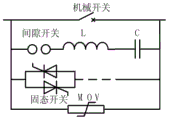
图2示出了本发明实施例的基于LC振荡强迫换流型机械式自动切换开关电路结构示意图;2 shows a schematic structural diagram of a forced commutation mechanical automatic switch circuit based on LC oscillation according to an embodiment of the present invention;
图3示出了根据本发明实施例的基于LC振荡强迫换流型机械式自动切换开关装置结构示意图;3 shows a schematic structural diagram of a forced commutation type mechanical automatic switch device based on LC oscillation according to an embodiment of the present invention;
图4示出了根据本发明实施例的双电源冗余供电系统结构示意图。FIG. 4 shows a schematic structural diagram of a dual power supply redundant power supply system according to an embodiment of the present invention.
具体实施方式Detailed ways
为使本发明实施例的目的、技术方案和优点更加清楚,下面将结合本发明实施例中的附图,对本发明实施例中的技术方案进行清楚、完整地说明,显然,所描述的实施例是本发明一部分实施例,而不是全部的实施例。基于本发明中的实施例,本领域普通技术人员在没有做出创造性劳动前提下所获得的所有其他实施例,都属于本发明保护的范围。In order to make the purposes, technical solutions and advantages of the embodiments of the present invention clearer, the technical solutions in the embodiments of the present invention will be clearly and completely described below with reference to the accompanying drawings in the embodiments of the present invention. Obviously, the described embodiments These are some embodiments of the present invention, but not all embodiments. Based on the embodiments of the present invention, all other embodiments obtained by those of ordinary skill in the art without creative efforts shall fall within the protection scope of the present invention.
本发明的切换开关装置采用了一种基于LC振荡强迫换流型机械式自动切换开关电路。本发明实施例以切换开关电路为例进行示例性说明,但本领域技术人员应当认识到,在不偏离本发明的基本发明构思的情况下,切换开关、断路器等所有能够实现电路通断的开关电路、元件、部件、设备、系统等均可实现本发明,这些都属于本发明的保护范围内。The switch device of the present invention adopts a forced commutation type mechanical automatic switch circuit based on LC oscillation. The embodiments of the present invention take a switch circuit as an example for illustrative description, but those skilled in the art should realize that, without departing from the basic inventive concept of the present invention, all devices such as a switch, circuit breaker, etc., which can realize circuit on-off Switching circuits, elements, components, equipment, systems, etc. can all implement the present invention, and these all fall within the protection scope of the present invention.
如图2所示,所述基于LC振荡强迫换流型机械式自动切换开关电路主要包括机械开关支路、LC振荡支路、固态开关支路和能量吸收支路,所述LC振荡支路、所述能量吸收支路、所述固态开关支路与所述机械开关支路并联。其中,所述机械开关支路主要包括机械开关。在所述开关电路正常运行时,电流流经所述机械开关实现向负荷供电;所述LC振荡支路主要包括间隙开关、电感L、电容C,并且所述间隙开关、所述电感L和电容C串联;所述固态开关支路包括一个或多个固态开关,在多个固态开关的情况下,多个固态开关串联连接。图2中固态开关所在的支路以断线表示可以一个固态开关或存在多个串联的固态开关,但并不表示固态开关所在的支路是电气断开的。所述能量吸收支路主要包括避雷器,实施例中采用了MOV(金属氧化物压敏电阻)氧化锌避雷器,避雷器吸收在所述机械开关的开合过程中所产生的剩余能量,进而实现对机械开关的过电压保护。本发明以MOV氧化锌避雷器作为示例性的能量吸收装置,但并不仅限于以MOV氧化锌避雷器作为能量吸收装置,所有能够吸收支路中剩余能量的能量吸收电路或系统均可用于本发明。As shown in Figure 2, the LC oscillation-based forced commutation type mechanical automatic switch circuit mainly includes a mechanical switch branch, an LC oscillation branch, a solid-state switch branch, and an energy absorption branch. The LC oscillation branch, The energy absorption branch, the solid state switch branch and the mechanical switch branch are connected in parallel. Wherein, the mechanical switch branch mainly includes a mechanical switch. When the switch circuit operates normally, the current flows through the mechanical switch to supply power to the load; the LC oscillation branch mainly includes a gap switch, an inductance L, and a capacitor C, and the gap switch, the inductance L, and the capacitor C is connected in series; the solid state switch branch includes one or more solid state switches, and in the case of multiple solid state switches, the multiple solid state switches are connected in series. In FIG. 2 , the branch where the solid-state switch is located is broken to indicate that there may be one solid-state switch or multiple solid-state switches connected in series, but it does not mean that the branch where the solid-state switch is located is electrically disconnected. The energy absorption branch mainly includes a surge arrester. In the embodiment, a MOV (metal oxide varistor) zinc oxide surge arrester is used. The surge arrester absorbs the residual energy generated during the opening and closing of the mechanical switch, thereby realizing the mechanical Overvoltage protection of the switch. The present invention uses the MOV zinc oxide arrester as an exemplary energy absorbing device, but is not limited to using the MOV zinc oxide arrester as the energy absorbing device. All energy absorbing circuits or systems that can absorb the remaining energy in the branch can be used in the present invention.
所述开关电路在正常运行以建立电源与负荷之间的连接时,所述开关支路中的所述机械开关处于闭合状态,间隙开关处于断开状态,通往负荷的电流流经所述机械开关。When the switch circuit is in normal operation to establish a connection between the power source and the load, the mechanical switch in the switch branch is in a closed state, the gap switch is in an open state, and the current to the load flows through the mechanical switch switch.
实施例所述的基于LC振荡强迫换流型机械式开关电路的分闸控制过程如下:向开关电路中机械开关支路中的机械开关发出分闸命令。机械开关在收到分闸命令后执行分闸动作,并在一定的时间t内,在触头开距达到2-3毫米(mm)后,达到有效开距。在所述机械开关已达到有效开距后,触发所述间隙开关支路中的间隙开关闭合,预充反向电压的振荡电容C与振荡电感L产生的振荡电流被叠加到机械开关支路,所述机械开关过零熄弧。在所述机械开关分闸运动到间隙所能够承受相应的瞬态恢复电压时,控制所述间隙开关断开,同时避雷器吸收系统剩余能量,分闸过程完成。The opening control process of the forced commutation mechanical switch circuit based on LC oscillation described in the embodiment is as follows: an opening command is issued to the mechanical switch in the branch of the mechanical switch in the switch circuit. The mechanical switch performs the opening action after receiving the opening command, and within a certain time t, after the contact opening distance reaches 2-3 millimeters (mm), the effective opening distance is reached. After the mechanical switch has reached the effective distance, the gap switch in the gap switch branch is triggered to close, and the oscillating current generated by the oscillating capacitor C and the oscillating inductance L precharged with the reverse voltage is superimposed on the mechanical switch branch. The mechanical switch zero-crosses the arc. When the mechanical switch moves to the point where the gap can withstand the corresponding transient recovery voltage, the gap switch is controlled to be disconnected, and the arrester absorbs the remaining energy of the system at the same time, and the opening process is completed.
实施例所述的基于LC振荡强迫换流型机械式开关电路的合闸控制过程如下:先导通固态开关,然后再闭合机械开关,也可以在导通固态开关的同时闭合机械开关,当电流转移至机械开关时,再断开固态开关。The closing control process of the forced commutation mechanical switch circuit based on LC oscillation described in the embodiment is as follows: the solid state switch is turned on first, and then the mechanical switch is closed, or the mechanical switch can be closed while the solid state switch is turned on. When the mechanical switch is reached, disconnect the solid state switch.
实施例还提供了一种开关部件,其采用了上述基于LC振荡强迫换流型机械式开关电路。该开关部件用于三相交流电系统中,每一相的电路分别采用上述基于LC振荡强迫换流型机械式开关电路。如图3所示,所述开关部件分别在A相、B相、C相中采用了上述自动切换开关电路:主切换开关部件中的A相、B相、C相(图中为了与备切换开关的三相线区分,A1、B1、C1来表示A相、B相、C相线)均采用了上述基于LC振荡强迫换流型机械式开关电路;备切换开关部件中的A相、B相、C相(图中为了与主切换开关的三相线区分,A2、B2、C2来表示A相、B相、C相线)同样均采用了上述基于LC振荡强迫换流型机械式开关电路。The embodiment also provides a switch component, which adopts the above-mentioned LC oscillation-based forced commutation type mechanical switch circuit. The switch component is used in a three-phase alternating current system, and the circuit of each phase adopts the above-mentioned forced commutation type mechanical switch circuit based on LC oscillation. As shown in FIG. 3 , the switch components respectively adopt the above-mentioned automatic transfer switch circuit in the A-phase, B-phase, and C-phase: A-phase, B-phase, and C-phase in the main switch-over switch component (in the figure, in order to switch with the standby switch) The three-phase lines of the switch are distinguished, A1, B1, and C1 represent A-phase, B-phase, and C-phase lines) all adopt the above-mentioned LC oscillation forced commutation mechanical switch circuit; Phase and C-phase (in order to distinguish from the three-phase line of the main switch in the figure, A2, B2, C2 represent A-phase, B-phase, C-phase line) also use the above-mentioned LC oscillation forced commutation type mechanical switch circuit.
如图3所示,实施例还提供了一种自动切换开关装置,所述自动切换开关装置包括两个上述开关部件,其中一个为主切换开关部件、另一个为备切换开关部件。正常工作过程中,所述主切换开关部件导通,实现电源通过所述主切换开关部件向所述负荷提供电流;所述备切换开关部件断开。出现故障需要将供电从主切换开关部件切换到备切换开关部件时,通过上述分闸控制过程断开所述主切换开关部件,并通过上述合闸控制过程接通所述备切换开关部件。As shown in FIG. 3 , the embodiment further provides an automatic transfer switch device, the automatic transfer switch device includes two above-mentioned switch components, one of which is a main switch component and the other is a backup switch component. During normal operation, the main switch part is turned on, so that the power supply provides current to the load through the main switch part; the backup switch part is disconnected. When a fault occurs and the power supply needs to be switched from the main switch part to the backup switch part, the main switch part is disconnected through the above-mentioned opening control process, and the standby switch part is turned on through the above-mentioned closing control process.
本实施例以双电源冗余供电系统来说明上述基于LC振荡强迫换流型机械式自动切换开关装置的控制使用。但是应该明确的是,上述实施例的基于LC振荡强迫换流型机械式自动切换开关装置并不仅限于双电源冗余供电系统,多电源冗余供电系统以及一般的诸如单电源供电系统、可以使用开关的电力系统等均可以使用上述实施例所述的基于LC振荡强迫换流型机械式自动切换开关装置。In this embodiment, a dual power supply redundant power supply system is used to illustrate the control and use of the above-mentioned LC oscillation-based forced commutation type mechanical automatic transfer switch device. However, it should be clear that the LC oscillation-based forced commutation type mechanical automatic transfer switch device in the above-mentioned embodiment is not limited to a dual power supply redundant power supply system, a multiple power supply redundant power supply system and a general power supply system such as a single power supply system. The switch power system and the like can all use the LC oscillation-based forced commutation type mechanical automatic transfer switch device described in the above embodiment.
如图4所示的根据本发明实施例的双电源冗余供电系统结构示意图。所述双电源供电系统包括电源、控制保护系统、自动切换开关装置、负荷以及由传感器等监测部件组成的监测系统,其中电源包括工作电源和备用电源两套电源,所述自动切换开关装置中的主切换开关部件与工作电源连接、备切换开关部件与备用电源连接。所述双电源冗余供电系统中工作电源支路上的主切换开关部件和/或备用电源支路上的备切换开关部件均可以使用上述实施例所述的基于LC振荡强迫换流型机械式自动切换开关部件。本实施例以工作电源支路上的切换开关和备用电源支路上的切换开关均使用上述基于LC振荡强迫换流型机械式自动切换开关部件为例进行示例性说明。FIG. 4 is a schematic structural diagram of a dual power supply redundant power supply system according to an embodiment of the present invention. The dual power supply system includes a power supply, a control and protection system, an automatic switching switch device, a load, and a monitoring system composed of monitoring components such as sensors, wherein the power supply includes two sets of power supplies, a working power supply and a backup power supply, and the automatic switching switch device is composed of two sets of power supplies. The main switch part is connected with the working power supply, and the backup switch part is connected with the backup power supply. In the dual power supply redundant power supply system, the main switch components on the working power supply branch and/or the standby switch components on the standby power supply branch can use the LC oscillation-based forced commutation type mechanical automatic switching described in the above embodiment. switch parts. This embodiment is exemplified by using the above-mentioned LC oscillation-based forced commutation type mechanical automatic switch component as an example for the switch on the working power supply branch and the switch on the standby power supply branch.
双电源冗余供电系统在正常供电状态下,所述自动切换开关装置中工作电源支路的主切换开关部件中的所有开关电路(也就是A、B、C相线路上的开关电路)均处于闭合状态,工作电源的电力通过所述切换开关装置提供给所述负荷;而所述自动切换开关装置中备用电源支路的备切换开关部件中的所有开关电路(也就是A、B、C相线路上的开关电路)均处于断开状态,所述备用电源不向所述负荷提供电力。In the normal power supply state of the dual power supply redundant power supply system, all the switch circuits (that is, the switch circuits on the A, B, and C phase lines) in the main switch component of the working power supply branch in the automatic transfer switch device are in In the closed state, the power of the working power supply is provided to the load through the transfer switch device; and all switch circuits (that is, phases A, B, and C) in the standby transfer switch components of the standby power supply branch in the automatic transfer switch device switch circuits on the line) are in an open state, and the backup power supply does not provide power to the load.
所述监测系统持续或周期性监测整个供电系统的工作状态,例如系统中的异常情况:工作电源支路中的传感器监测工作电源的工作状态、备用电源支路中的传感器监测备用电源的工作状态、负荷支路中的传感器监测负荷的工作状态。The monitoring system continuously or periodically monitors the working state of the entire power supply system, such as abnormal conditions in the system: the sensor in the working power supply branch monitors the working state of the working power supply, and the sensor in the backup power supply branch monitors the working state of the backup power supply , The sensor in the load branch monitors the working state of the load.
所述监测系统检测到工作电源故障或压降过大时,向控制保护系统发送相应的故障信号。控制保护系统在接收到监测系统发来的表示工作电源发生故障的信号后,判断工作电源出现故障,需要将电源从工作电源切换到备用电源上。此时,控制保护系统中的控制单元向工作电源的切换开关部件发送分闸命令、并向备用电源的切换开关部件发送合闸命令,从而控制工作电源的切换开关部件断开连接,而控制备用电源的切换开关部件闭合以建立备用电源与负荷之间的电气连接,从而通过备用电源箱负荷提供电力。The monitoring system sends a corresponding fault signal to the control and protection system when it detects that the working power supply is faulty or the voltage drop is too large. After receiving the signal indicating the failure of the working power supply from the monitoring system, the control and protection system judges that the working power supply is faulty and needs to switch the power supply from the working power supply to the standby power supply. At this time, the control unit in the control protection system sends an opening command to the switch part of the working power supply and a closing command to the switch part of the standby power supply, thereby controlling the switch part of the working power supply to disconnect and control the standby power supply. The transfer switch component of the power source is closed to establish an electrical connection between the backup power source and the load, thereby providing power through the backup power box load.
正常运行时,主切换开关部件中A相、B相和C相线上的所有机械开关均处于闭合状态,各个相线上的电流流经各自的机械开关向负荷提供电力。在传感器监测到工作电源发生故障时,向控制保护系统发送报警信息。接收到所述报警信息后,控制保护系统中的控制单元向所述自动切换开关装置中的主切换开关部件的机械开关发出分闸命令。在机械开关达到有效开距后,触发所述主切换开关部件的各个所述间隙开关支路中的间隙开关闭合,预充反向电压的振荡电容C与振荡电感L产生的振荡电流被叠加到其并联的机械开关支路上,各个所述机械开关过零熄弧。在所述机械开关分闸运动到间隙所能够承受相应的瞬态恢复电压时,控制所述间隙开关断开,同时避雷器吸收系统剩余能量,分闸过程完成。During normal operation, all mechanical switches on the A-phase, B-phase and C-phase lines in the main transfer switch unit are closed, and the current on each phase line flows through the respective mechanical switches to provide power to the load. When the sensor detects the failure of the working power supply, it sends alarm information to the control and protection system. After receiving the alarm information, the control unit in the control and protection system issues an opening command to the mechanical switch of the main diverter switch component in the automatic diverter switch device. After the mechanical switch reaches an effective distance, the gap switches in each of the gap switch branches of the main switch component are triggered to close, and the oscillating current generated by the oscillating capacitor C and oscillating inductance L precharged with reverse voltage is superimposed to On the branches of the mechanical switches connected in parallel, each of the mechanical switches crosses zero and extinguishes the arc. When the mechanical switch moves to the point where the gap can withstand the corresponding transient recovery voltage, the gap switch is controlled to be disconnected, and the arrester absorbs the remaining energy of the system at the same time, and the opening process is completed.
此时,控制保护系统中的控制单元还向备切换开关发出合闸命令。备切换开关部件收到所述控制保护系统发送来的合闸命令后,先导通固态开关,然后再闭合机械开关,也可以在导通固态开关的同时闭合机械开关,当电流转移至机械开关时,再断开固态开关,从而实现对备用电源支路中的切换开关装置的合闸,使得备用工作电源对所述负荷供电。At this time, the control unit in the control protection system also issues a closing command to the standby diverter switch. After receiving the closing command sent by the control and protection system, the standby diverter switch component turns on the solid state switch first, and then closes the mechanical switch, or closes the mechanical switch while turning on the solid state switch. When the current is transferred to the mechanical switch , and then disconnect the solid-state switch, thereby realizing the closing of the switch device in the standby power supply branch, so that the standby working power supply supplies power to the load.
所述双电源冗余供电系统中从备用电源向负荷提供电力切换到从工作电源向所述负荷提供电力的过程与从工作电源向负荷提供电力切换到从备用电源向所述负荷提供电力的过程相似,在此不再赘述。In the dual power redundant power supply system, the process of switching from supplying power to the load from the standby power supply to supplying power to the load from the working power supply and the process of switching from supplying power to the load from the working power supply to supplying power to the load from the standby power supply similar, and will not be repeated here.
负荷支路中的传感器在监测到所述负荷出现故障后,会将监测到的故障信息发送给控制保护系统。所述控制保护系统可以根据所述故障信息关闭工作电源支路和备用电源支路中的切换开关部件,以断开任何电源向所述负荷供电。After monitoring the failure of the load, the sensor in the load branch will send the monitored failure information to the control and protection system. The control and protection system can turn off the switch components in the working power supply branch and the backup power supply branch according to the fault information, so as to disconnect any power supply to supply power to the load.
所述监测系统同时检测切换开断状态,并将状态信息反馈回所述控制保护系统,以确保开断和导通。The monitoring system simultaneously detects the switching off state, and feeds back the state information to the control and protection system to ensure the off and on.
控制保护系统还根据接收的信息实现对其他联络开关的控制或接收其他联络开关的状态信息,并将接收的所有信息发送给远程计算机,同时可以从远程计算机中接收信息,例如控制相关切换开关进行开启或闭合的信息。The control protection system also realizes the control of other tie switches or receives the status information of other tie switches according to the received information, and sends all the received information to the remote computer. Open or closed information.
实施例中以三相交流电为例进行示例性说明,但本领域技术人员应当认识到,在不偏离本发明的基本发明构思的情况下,本发明的开关电路、开关装置、系统及其控制方法并不仅限于说明书中基于示例性说明目的的三相交流电,本发明的开关电路、开关装置、系统及其控制方法适用于包括但不限于直流电和交流电的系统中。In the embodiments, three-phase alternating current is taken as an example for illustration, but those skilled in the art should realize that the switch circuit, switch device, system and control method thereof of the present invention will not deviate from the basic inventive concept of the present invention. Not limited to the three-phase alternating current for the purpose of illustration in the specification, the switching circuit, switching device, system and control method thereof of the present invention are applicable to systems including but not limited to direct current and alternating current.
显然,本领域的技术人员可以对本发明进行各种改动和变型而不脱离本发明的精神和范围。这样,倘若本发明的这些修改和变型属于本发明权利要求及其等同技术的范围之内,则本发明也意图包含这些改动和变型在内。It will be apparent to those skilled in the art that various modifications and variations can be made in the present invention without departing from the spirit and scope of the invention. Thus, provided that these modifications and variations of the present invention fall within the scope of the claims of the present invention and their equivalents, the present invention is also intended to include these modifications and variations.
Claims (10)
Priority Applications (1)
| Application Number | Priority Date | Filing Date | Title |
|---|---|---|---|
| CN201711010698.5A CN107769195B (en) | 2017-10-25 | 2017-10-25 | Forced commutation mechanical switch, device, and control method based on LC oscillation |
Applications Claiming Priority (1)
| Application Number | Priority Date | Filing Date | Title |
|---|---|---|---|
| CN201711010698.5A CN107769195B (en) | 2017-10-25 | 2017-10-25 | Forced commutation mechanical switch, device, and control method based on LC oscillation |
Publications (2)
| Publication Number | Publication Date |
|---|---|
| CN107769195A CN107769195A (en) | 2018-03-06 |
| CN107769195B true CN107769195B (en) | 2020-07-03 |
Family
ID=61271663
Family Applications (1)
| Application Number | Title | Priority Date | Filing Date |
|---|---|---|---|
| CN201711010698.5A Active CN107769195B (en) | 2017-10-25 | 2017-10-25 | Forced commutation mechanical switch, device, and control method based on LC oscillation |
Country Status (1)
| Country | Link |
|---|---|
| CN (1) | CN107769195B (en) |
Families Citing this family (3)
| Publication number | Priority date | Publication date | Assignee | Title |
|---|---|---|---|---|
| CN109346939B (en) * | 2018-11-30 | 2024-01-23 | 清华四川能源互联网研究院 | Change-over switch cabinet device |
| CN110635558A (en) * | 2019-09-17 | 2019-12-31 | 珠海华创泰能能源科技有限公司 | Electromechanical integrated combined fast switch |
| CN114156841A (en) * | 2021-10-18 | 2022-03-08 | 国网河北省电力有限公司电力科学研究院 | A new type of commutation circuit topology with high current forced commutation breaking |
Citations (3)
| Publication number | Priority date | Publication date | Assignee | Title |
|---|---|---|---|---|
| JPH09231877A (en) * | 1996-02-20 | 1997-09-05 | Fuji Electric Co Ltd | DC circuit breaker |
| CN103532218A (en) * | 2013-10-25 | 2014-01-22 | 国家电网公司 | Rapid double power supply switch device and working method thereof |
| CN104578155A (en) * | 2013-10-29 | 2015-04-29 | 通用电气公司 | Power generation system and method with fault ride through capability |
Family Cites Families (1)
| Publication number | Priority date | Publication date | Assignee | Title |
|---|---|---|---|---|
| US9225179B2 (en) * | 2011-10-12 | 2015-12-29 | Texas Instruments Incorporated | Capacitor-based active balancing for batteries and other power supplies |
-
2017
- 2017-10-25 CN CN201711010698.5A patent/CN107769195B/en active Active
Patent Citations (3)
| Publication number | Priority date | Publication date | Assignee | Title |
|---|---|---|---|---|
| JPH09231877A (en) * | 1996-02-20 | 1997-09-05 | Fuji Electric Co Ltd | DC circuit breaker |
| CN103532218A (en) * | 2013-10-25 | 2014-01-22 | 国家电网公司 | Rapid double power supply switch device and working method thereof |
| CN104578155A (en) * | 2013-10-29 | 2015-04-29 | 通用电气公司 | Power generation system and method with fault ride through capability |
Also Published As
| Publication number | Publication date |
|---|---|
| CN107769195A (en) | 2018-03-06 |
Similar Documents
| Publication | Publication Date | Title |
|---|---|---|
| CN107786188B (en) | Forced commutation compound switch based on LC oscillation | |
| CN107769369B (en) | A Hybrid Switch Based on Coupling Negative Voltage Circuit | |
| CN104242265B (en) | All-solid-state direct-current circuit breaker of direct-current power distribution network | |
| CN103337851B (en) | A kind of half control type active injection current high voltage direct current breaker and its implementation | |
| CN104900444B (en) | Topology Structure and Control Method of DC Circuit Breaker | |
| WO2017181927A1 (en) | Direct current switch-off device and control method thereof | |
| CN103646805B (en) | A kind of direct-current breaker topology | |
| CN108599099B (en) | A kind of multi-line dc circuit breaker and cutoff method | |
| CN104113057B (en) | A kind of combined DC switchgear and control method thereof | |
| CN103457257A (en) | Direct-current breaker used for multi-terminal direct-current system and control method thereof | |
| CN114172135B (en) | A double main break type multi-port hybrid DC circuit breaker suitable for multi-terminal DC power grids | |
| CN107769195B (en) | Forced commutation mechanical switch, device, and control method based on LC oscillation | |
| CN111640602A (en) | Multi-fracture direct-current switch equipment with controllable transfer branch oscillation current and control method | |
| CN103441490A (en) | Direct-current breaker used for multi-terminal direct current system and control method of direct-current breaker | |
| CN102946106B (en) | Silicon controlled rectifier combination switch | |
| CN211089218U (en) | High-capacity high-reliability rapid power supply switching device | |
| CN107896102B (en) | A hybrid switch with a main channel series solid-state switch | |
| CN111934290A (en) | A kind of multi-terminal DC circuit breaker and its control method | |
| CN107846211B (en) | Hybrid switch with main path series solid state switch | |
| CN205811651U (en) | A Switching Circuit Facilitating Offline Maintenance of UPS | |
| CN202949229U (en) | Controllable silicon composite switch | |
| CN108390453A (en) | It is a kind of based on coupling negative pressure circuit composite switch and device, protection system | |
| CN108321922A (en) | Mechanically switch switch and device, protection system based on LC oscillation forced commutation types | |
| CN109545621A (en) | A kind of driving circuit applied to the high-power contactor of aerospace | |
| CN201259827Y (en) | Thyristor reactor transition loaded adapter switch without quick mechanism |
Legal Events
| Date | Code | Title | Description |
|---|---|---|---|
| PB01 | Publication | ||
| PB01 | Publication | ||
| SE01 | Entry into force of request for substantive examination | ||
| SE01 | Entry into force of request for substantive examination | ||
| GR01 | Patent grant | ||
| GR01 | Patent grant |