CN107577361B - Coordinate measuring device and method for identifying position of contact object - Google Patents
Coordinate measuring device and method for identifying position of contact object Download PDFInfo
- Publication number
- CN107577361B CN107577361B CN201710800002.2A CN201710800002A CN107577361B CN 107577361 B CN107577361 B CN 107577361B CN 201710800002 A CN201710800002 A CN 201710800002A CN 107577361 B CN107577361 B CN 107577361B
- Authority
- CN
- China
- Prior art keywords
- coordinate
- electrode
- signal
- indicating device
- measurement device
- Prior art date
- Legal status (The legal status is an assumption and is not a legal conclusion. Google has not performed a legal analysis and makes no representation as to the accuracy of the status listed.)
- Expired - Fee Related
Links
Images


Classifications
-
- G—PHYSICS
- G06—COMPUTING OR CALCULATING; COUNTING
- G06F—ELECTRIC DIGITAL DATA PROCESSING
- G06F3/00—Input arrangements for transferring data to be processed into a form capable of being handled by the computer; Output arrangements for transferring data from processing unit to output unit, e.g. interface arrangements
- G06F3/01—Input arrangements or combined input and output arrangements for interaction between user and computer
- G06F3/03—Arrangements for converting the position or the displacement of a member into a coded form
- G06F3/041—Digitisers, e.g. for touch screens or touch pads, characterised by the transducing means
- G06F3/044—Digitisers, e.g. for touch screens or touch pads, characterised by the transducing means by capacitive means
- G06F3/0441—Digitisers, e.g. for touch screens or touch pads, characterised by the transducing means by capacitive means using active external devices, e.g. active pens, for receiving changes in electrical potential transmitted by the digitiser, e.g. tablet driving signals
-
- G—PHYSICS
- G06—COMPUTING OR CALCULATING; COUNTING
- G06F—ELECTRIC DIGITAL DATA PROCESSING
- G06F3/00—Input arrangements for transferring data to be processed into a form capable of being handled by the computer; Output arrangements for transferring data from processing unit to output unit, e.g. interface arrangements
- G06F3/01—Input arrangements or combined input and output arrangements for interaction between user and computer
- G06F3/03—Arrangements for converting the position or the displacement of a member into a coded form
- G06F3/033—Pointing devices displaced or positioned by the user, e.g. mice, trackballs, pens or joysticks; Accessories therefor
- G06F3/0354—Pointing devices displaced or positioned by the user, e.g. mice, trackballs, pens or joysticks; Accessories therefor with detection of 2D relative movements between the device, or an operating part thereof, and a plane or surface, e.g. 2D mice, trackballs, pens or pucks
- G06F3/03545—Pens or stylus
-
- G—PHYSICS
- G06—COMPUTING OR CALCULATING; COUNTING
- G06F—ELECTRIC DIGITAL DATA PROCESSING
- G06F3/00—Input arrangements for transferring data to be processed into a form capable of being handled by the computer; Output arrangements for transferring data from processing unit to output unit, e.g. interface arrangements
- G06F3/01—Input arrangements or combined input and output arrangements for interaction between user and computer
- G06F3/03—Arrangements for converting the position or the displacement of a member into a coded form
- G06F3/033—Pointing devices displaced or positioned by the user, e.g. mice, trackballs, pens or joysticks; Accessories therefor
- G06F3/038—Control and interface arrangements therefor, e.g. drivers or device-embedded control circuitry
-
- G—PHYSICS
- G06—COMPUTING OR CALCULATING; COUNTING
- G06F—ELECTRIC DIGITAL DATA PROCESSING
- G06F3/00—Input arrangements for transferring data to be processed into a form capable of being handled by the computer; Output arrangements for transferring data from processing unit to output unit, e.g. interface arrangements
- G06F3/01—Input arrangements or combined input and output arrangements for interaction between user and computer
- G06F3/03—Arrangements for converting the position or the displacement of a member into a coded form
- G06F3/041—Digitisers, e.g. for touch screens or touch pads, characterised by the transducing means
- G06F3/0416—Control or interface arrangements specially adapted for digitisers
- G06F3/04164—Connections between sensors and controllers, e.g. routing lines between electrodes and connection pads
-
- G—PHYSICS
- G06—COMPUTING OR CALCULATING; COUNTING
- G06F—ELECTRIC DIGITAL DATA PROCESSING
- G06F3/00—Input arrangements for transferring data to be processed into a form capable of being handled by the computer; Output arrangements for transferring data from processing unit to output unit, e.g. interface arrangements
- G06F3/01—Input arrangements or combined input and output arrangements for interaction between user and computer
- G06F3/03—Arrangements for converting the position or the displacement of a member into a coded form
- G06F3/041—Digitisers, e.g. for touch screens or touch pads, characterised by the transducing means
- G06F3/0416—Control or interface arrangements specially adapted for digitisers
- G06F3/04166—Details of scanning methods, e.g. sampling time, grouping of sub areas or time sharing with display driving
-
- G—PHYSICS
- G06—COMPUTING OR CALCULATING; COUNTING
- G06F—ELECTRIC DIGITAL DATA PROCESSING
- G06F3/00—Input arrangements for transferring data to be processed into a form capable of being handled by the computer; Output arrangements for transferring data from processing unit to output unit, e.g. interface arrangements
- G06F3/01—Input arrangements or combined input and output arrangements for interaction between user and computer
- G06F3/03—Arrangements for converting the position or the displacement of a member into a coded form
- G06F3/041—Digitisers, e.g. for touch screens or touch pads, characterised by the transducing means
- G06F3/044—Digitisers, e.g. for touch screens or touch pads, characterised by the transducing means by capacitive means
- G06F3/0442—Digitisers, e.g. for touch screens or touch pads, characterised by the transducing means by capacitive means using active external devices, e.g. active pens, for transmitting changes in electrical potential to be received by the digitiser
-
- G—PHYSICS
- G06—COMPUTING OR CALCULATING; COUNTING
- G06F—ELECTRIC DIGITAL DATA PROCESSING
- G06F3/00—Input arrangements for transferring data to be processed into a form capable of being handled by the computer; Output arrangements for transferring data from processing unit to output unit, e.g. interface arrangements
- G06F3/01—Input arrangements or combined input and output arrangements for interaction between user and computer
- G06F3/03—Arrangements for converting the position or the displacement of a member into a coded form
- G06F3/041—Digitisers, e.g. for touch screens or touch pads, characterised by the transducing means
- G06F3/044—Digitisers, e.g. for touch screens or touch pads, characterised by the transducing means by capacitive means
- G06F3/0446—Digitisers, e.g. for touch screens or touch pads, characterised by the transducing means by capacitive means using a grid-like structure of electrodes in at least two directions, e.g. using row and column electrodes
-
- G—PHYSICS
- G06—COMPUTING OR CALCULATING; COUNTING
- G06F—ELECTRIC DIGITAL DATA PROCESSING
- G06F3/00—Input arrangements for transferring data to be processed into a form capable of being handled by the computer; Output arrangements for transferring data from processing unit to output unit, e.g. interface arrangements
- G06F3/01—Input arrangements or combined input and output arrangements for interaction between user and computer
- G06F3/03—Arrangements for converting the position or the displacement of a member into a coded form
- G06F3/041—Digitisers, e.g. for touch screens or touch pads, characterised by the transducing means
- G06F3/044—Digitisers, e.g. for touch screens or touch pads, characterised by the transducing means by capacitive means
- G06F3/0447—Position sensing using the local deformation of sensor cells
-
- G—PHYSICS
- G06—COMPUTING OR CALCULATING; COUNTING
- G06F—ELECTRIC DIGITAL DATA PROCESSING
- G06F2203/00—Indexing scheme relating to G06F3/00 - G06F3/048
- G06F2203/041—Indexing scheme relating to G06F3/041 - G06F3/045
- G06F2203/04104—Multi-touch detection in digitiser, i.e. details about the simultaneous detection of a plurality of touching locations, e.g. multiple fingers or pen and finger
-
- G—PHYSICS
- G06—COMPUTING OR CALCULATING; COUNTING
- G06F—ELECTRIC DIGITAL DATA PROCESSING
- G06F2203/00—Indexing scheme relating to G06F3/00 - G06F3/048
- G06F2203/041—Indexing scheme relating to G06F3/041 - G06F3/045
- G06F2203/04105—Pressure sensors for measuring the pressure or force exerted on the touch surface without providing the touch position
-
- G—PHYSICS
- G06—COMPUTING OR CALCULATING; COUNTING
- G06F—ELECTRIC DIGITAL DATA PROCESSING
- G06F2203/00—Indexing scheme relating to G06F3/00 - G06F3/048
- G06F2203/041—Indexing scheme relating to G06F3/041 - G06F3/045
- G06F2203/04106—Multi-sensing digitiser, i.e. digitiser using at least two different sensing technologies simultaneously or alternatively, e.g. for detecting pen and finger, for saving power or for improving position detection
Landscapes
- Engineering & Computer Science (AREA)
- General Engineering & Computer Science (AREA)
- Theoretical Computer Science (AREA)
- Human Computer Interaction (AREA)
- Physics & Mathematics (AREA)
- General Physics & Mathematics (AREA)
- Computer Networks & Wireless Communication (AREA)
- Measurement Of Length, Angles, Or The Like Using Electric Or Magnetic Means (AREA)
- Position Input By Displaying (AREA)
Abstract
公开了用于识别接触物体的位置的坐标测量装置和识别接触物体的位置的方法。该坐标测量装置包括:至少一个电极,被配置为:传送通过向所述至少一个电极提供电流而生成的传输信号,以及接收从所述接触物体传送的接收信号,所述传输信号被提供给所述接触物体,并且所述接收信号基于所述传输信号而生成;以及控制器,被配置为:基于通过所述至少一个电极接收的所述接收信号或在所述至少一个电极中的电容改变中的至少一个来识别所述接触物体的位置,所述电容改变基于所述接触物体对所述坐标测量装置的接触而生成,以及其中,所述控制器还被配置为基于所述接收信号确定所述接触物体的类型。

A coordinate measuring device for identifying the position of a contacting object and a method for identifying the position of the contacting object are disclosed. The coordinate measuring device includes at least one electrode configured to transmit a transmission signal generated by supplying an electric current to the at least one electrode, and to receive a reception signal transmitted from the contact object, the transmission signal being provided to the at least one electrode. the contact object, and the received signal is generated based on the transmitted signal; and a controller configured to: based on the received signal received by the at least one electrode or in a change in capacitance in the at least one electrode at least one of the contacting objects to identify the location of the contacting object, the capacitance change being generated based on the contacting of the contacting object with the coordinate measuring device, and wherein the controller is further configured to determine the location of the contacting object based on the received signal Describe the type of contact object.
Description
本申请是申请日为2013年05月13日,申请号为201310175407.3,发明名称为“坐标指示装置和用于其输入位置的坐标测量装置”的专利申请的分案申请。This application is a divisional application of a patent application whose filing date is May 13, 2013, the application number is 201310175407.3, and the invention title is "Coordinate Indicating Device and Coordinate Measuring Device for Inputting Position thereof".
技术领域technical field
本发明一般涉及坐标指示装置和用于测量坐标指示装置的输入位置的坐标测量装置,更具体地,涉及诸如手指或手写笔的坐标指示装置和用于测量该坐标指示装置的输入位置的坐标测量装置。The present invention generally relates to a coordinate indicating device and a coordinate measuring device for measuring an input position of the coordinate indicating device, and more particularly, to a coordinate indicating device such as a finger or a stylus and a coordinate measuring device for measuring the input position of the coordinate indicating device device.
背景技术Background technique
当前,正在对具有嵌入其中接触位置测量装置的能力的、诸如智能电话和平板PC的设备进行积极地开发。具体地说,智能电话或平板PC一般包括触摸屏,而用户通过使用手机或手写笔来指定触摸屏的特定坐标。用户通过指定触摸屏的特定坐标在智能电话中输入特定信号。Currently, devices, such as smart phones and tablet PCs, with the ability to have contact position measurement devices embedded therein are actively developed. Specifically, a smartphone or tablet PC generally includes a touch screen, and a user specifies specific coordinates of the touch screen by using a cell phone or a stylus. The user inputs a specific signal in the smartphone by specifying specific coordinates of the touch screen.
触摸屏可以基于电、红外光、超声波等等来辨识(recognize)输入。例如,基于电的设备包括电阻型触摸屏(R型触摸屏)或电容型触摸屏(C型触摸屏)。在触摸屏中,能够辨识用户手指和手写笔的R型触摸屏已经被广泛地使用,但是R型触摸屏具有这样的问题:由于铟锡氧化物(ITO)层之间的空气空间(air space),而存在屏幕眩光。更具体地,由于ITO层之间的空气空间,穿透显示器的光的透射率降低,而外部的光的反射增强。The touch screen can recognize input based on electricity, infrared light, ultrasound, and the like. For example, electrical-based devices include resistive touchscreens (R-type touchscreens) or capacitive touchscreens (C-type touchscreens). Among the touchscreens, R-type touchscreens capable of recognizing a user's finger and a stylus have been widely used, but the R-type touchscreens have such a problem that due to the air space between the indium tin oxide (ITO) layers, the There is screen glare. More specifically, due to the air space between the ITO layers, the transmittance of light penetrating the display is reduced, while the reflection of external light is enhanced.
当前,C型触摸屏也被广泛地应用。C型触摸屏通过检测由物体的接触产生的透明电极的电容中的差来操作。然而,C型触摸屏在物理地区分手与笔方面存在困难,导致由手的接触引起的意料之外的操作错误,该操作错误可能在使用笔时发生。Currently, C-type touch screens are also widely used. The C-type touch screen operates by detecting the difference in the capacitance of the transparent electrodes produced by the contact of an object. However, the C-type touch screen has difficulties in physically distinguishing the hand from the pen, resulting in unexpected operational errors caused by the contact of the hand, which may occur while using the pen.
用于根据接触面积来区分手和笔的软件和包括诸如电磁共振(EMR)技术以及C型触摸屏的单独的位置测量装置的设备已经被用于解决接触问题。然而,软件不能完全解决由于手的接触而产生的意料之外的操作错误,并且实现包括单独的测量装置的方法由于需要额外的组件而增加了尺寸、重量、以及设备的成本。Software for differentiating hand and pen based on contact area and equipment including separate position measurement devices such as Electromagnetic Resonance (EMR) technology and C-type touchscreens have been used to address the contact problem. However, software cannot fully address unanticipated operational errors due to hand contact, and implementing a method that includes a separate measurement device increases size, weight, and cost of equipment due to the need for additional components.
因此,需要能够当使用诸如手写笔的物体时,不使用单独的位置测量装置来执行无操作错误的确定的技术。Therefore, there is a need for a technique capable of performing an operation error-free determination without using a separate position measurement device when an object such as a stylus is used.
发明内容SUMMARY OF THE INVENTION
因此,本发明的方面是解决以上提到的、出现在已有技术中的问题,并且提供至少以下的优点。根据本发明的方面,提供了坐标指示装置和坐标测量装置,坐标测量装置确定手写笔和导电物体的输入位置而只包括单一触摸屏。根据本发明的又一个方面,提供了坐标指示装置和坐标测量装置,坐标测量装置区分包括手写笔和诸如手指的其它导电物体的接触物体的类型。Accordingly, aspects of the present invention are to solve the above-mentioned problems occurring in the prior art, and to provide at least the following advantages. According to an aspect of the present invention, there are provided a coordinate indicating device and a coordinate measuring device that determine input positions of a stylus and a conductive object and include only a single touch screen. According to yet another aspect of the present invention, there are provided a coordinate indicating device and a coordinate measuring device that distinguish between types of contact objects including a stylus and other conductive objects such as fingers.
根据本发明的一个方面,提供了坐标测量系统,其包括坐标指示装置和用于确定包括坐标指示装置的接触物体的位置的坐标测量装置。坐标测量装置包括:通道电极(channel electrode)单元,其包括一个或多个电极,其中,一个或多个电极中的每一个的电容或者一个或多个电极之间的电容基于接触物体的位置的改变而改变;和控制器,用于将电信号施加到通道电极单元或者测量输入到通道电极单元的接收信号。坐标指示装置包括:导电尖端(conductive tip),用于与通道电极单元的一个或多个电极形成电容;和共振电路单元,用于生成坐标指示装置的标识(identification)信息,其中,共振电路单元连接到导电尖端,其中,控制器基于一个或多个电极中的每一个的电容或者一个或多个电极之间的电容的改变来确定接触物体的输入位置,并且基于接收信号的频率响应特性来区分接触物体的类型。According to one aspect of the present invention, there is provided a coordinate measuring system comprising a coordinate indicating device and a coordinate measuring device for determining the position of a contacting object including the coordinate indicating device. The coordinate measuring device includes a channel electrode unit comprising one or more electrodes, wherein the capacitance of each of the one or more electrodes or the capacitance between the one or more electrodes is dependent on the position of the contacting object and a controller for applying an electrical signal to the channel electrode unit or measuring a received signal input to the channel electrode unit. The coordinate indicating device includes: a conductive tip for forming capacitance with one or more electrodes of the channel electrode unit; and a resonance circuit unit for generating identification information of the coordinate indicating device, wherein the resonance circuit unit connected to the conductive tip, wherein the controller determines the input location of the contacting object based on the capacitance of each of the one or more electrodes or a change in capacitance between the one or more electrodes, and based on the frequency response characteristics of the received signal Distinguish the type of contact object.
根据本发明的另一个方面,提供了坐标测量系统,其包括坐标指示装置和用于确定包括坐标指示装置的接触物体的位置的坐标测量装置。坐标测量装置包括:通道电极单元,其包括一个或多个电极,其中,一个或多个电极中的每一个的电容或者一个或多个电极之间的电容基于接触物体的位置的改变而改变;驱动器,用于将电驱动信号施加到通道电极单元;检测器,用于检测通道电极单元的接收信号;和控制器,用于确定接触物体的位置和接触物体的类型。坐标指示装置包括用于输出坐标指示装置的标识信息的共振电路单元,其中,控制器在驱动器施加电驱动信号的第一时段基于由检测器检测的接收信号确定接触物体的位置,并且在驱动器不施加电驱动信号的第二时段基于由检测器检测的接收信号确定接触物体的类型。According to another aspect of the present invention, there is provided a coordinate measuring system comprising a coordinate indicating device and a coordinate measuring device for determining the position of a contacting object including the coordinate indicating device. The coordinate measurement device includes: a channel electrode unit including one or more electrodes, wherein the capacitance of each of the one or more electrodes or the capacitance between the one or more electrodes changes based on a change in the position of the contacting object; a driver for applying an electrical drive signal to the channel electrode unit; a detector for detecting a received signal of the channel electrode unit; and a controller for determining the position of the contact object and the type of the contact object. The coordinate indicating device includes a resonance circuit unit for outputting identification information of the coordinate indicating device, wherein the controller determines the position of the contacting object based on the received signal detected by the detector during the first period of time when the driver applies the electric drive signal, and when the driver does not The second period of time during which the electrical drive signal is applied determines the type of contacting object based on the received signal detected by the detector.
根据本发明的另一个方面,提供了坐标测量系统,其包括坐标指示装置以及用于确定与坐标指示装置和导电物体中的至少一个相应的接触物体的位置的坐标测量装置。坐标测量装置包括:通道电极单元,其包括一个或多个电极,其中,一个或多个电极中的每一个的电容或者一个或多个电极之间的电容基于坐标指示装置的位置的改变而改变;和控制器,用于将具有两个或更多个不同频率的电信号施加到通道电极单元或者测量由通道电极单元接收的接收信号。坐标指示装置包括用于输出坐标指示装置的标识信息的共振电路单元,其中,控制器从对于一个频率的响应特性来确定接触物体的位置,并且从对于其它频率的响应特性确定接触物体的类型和接触压力中的至少一个。According to another aspect of the present invention, there is provided a coordinate measuring system comprising a coordinate indicating device and a coordinate measuring device for determining a position of a contacting object corresponding to at least one of the coordinate indicating device and a conductive object. The coordinate measuring device includes a channel electrode unit including one or more electrodes, wherein the capacitance of each of the one or more electrodes or the capacitance between the one or more electrodes changes based on a change in the position of the coordinate indicating device and a controller for applying electrical signals having two or more different frequencies to the channel electrode unit or measuring a received signal received by the channel electrode unit. The coordinate indicating device includes a resonance circuit unit for outputting identification information of the coordinate indicating device, wherein the controller determines the position of the contacting object from the response characteristics for one frequency, and determines the type and type of the contacting object from the response characteristics for other frequencies. At least one of the contact pressures.
根据本发明的另一个方面,提供了坐标测量系统,其包括坐标指示装置以及用于确定坐标指示装置的位置的坐标测量装置。坐标测量装置包括:通道电极单元,其包括一个或多个电极,其中,一个或多个电极中的每一个的电容或者一个或多个电极之间的电容基于坐标指示装置的位置的改变而改变;驱动器,用于将电信号施加到通道电极单元;接收器,用于从通道电极单元接收电信号;和控制器,用于确定坐标指示装置的接触压力。坐标指示装置包括用于与驱动器交换电信号的导电尖端,其中,导电尖端与通道电极单元电容性耦合;和连接到导电尖端的无源电路,其中,无源电路的响应特性根据坐标指示装置的接触压力而改变,其中,控制器基于由检测器在相等时段的两个或更多个不同部分(section)中检测的无源电路的响应特性来测量坐标指示装置的接触压力。According to another aspect of the present invention, there is provided a coordinate measuring system comprising a coordinate indicating device and a coordinate measuring device for determining the position of the coordinate indicating device. The coordinate measuring device includes a channel electrode unit including one or more electrodes, wherein the capacitance of each of the one or more electrodes or the capacitance between the one or more electrodes changes based on a change in the position of the coordinate indicating device a driver for applying an electrical signal to the channel electrode unit; a receiver for receiving the electrical signal from the channel electrode unit; and a controller for determining the contact pressure of the coordinate indicating device. The coordinate indicating device includes a conductive tip for exchanging electrical signals with the driver, wherein the conductive tip is capacitively coupled to the channel electrode unit; and a passive circuit connected to the conductive tip, wherein a response characteristic of the passive circuit is based on the coordinate indicating device contact pressure, wherein the controller measures the contact pressure of the coordinate indicating device based on the response characteristics of the passive circuit detected by the detector in two or more different sections of equal time period.
根据本发明的另一个方面,提供了坐标测量系统,其包括坐标指示装置以及用于确定包括坐标指示装置的接触物体的位置的坐标测量装置。坐标测量装置包括:通道电极单元,其包括一个或多个电极,其中,一个或多个电极中的每一个的电容或者一个或多个电极之间的电容基于接触物体的位置的改变而改变;和控制器,用于将电信号施加到通道电极单元或者测量通道电极单元的接收信号。坐标指示装置包括:导电尖端,用于与通道电极单元的一个或多个电极形成电容;接地单元,用于通过直接接触和电容性耦合中的至少一个来形成与用户的电连接;共振电路单元,其连接到导电尖端;和开关单元,用于当导电尖端的接触压力等于或大于预先设定的阈值时形成共振,并且当导电尖端的接触压力小于预先设定的阈值时不形成共振。According to another aspect of the present invention, there is provided a coordinate measuring system comprising a coordinate indicating device and a coordinate measuring device for determining the position of a contacting object including the coordinate indicating device. The coordinate measurement device includes: a channel electrode unit including one or more electrodes, wherein the capacitance of each of the one or more electrodes or the capacitance between the one or more electrodes changes based on a change in the position of the contacting object; and a controller for applying an electrical signal to the channel electrode unit or measuring a received signal of the channel electrode unit. The coordinate indicating device includes: a conductive tip for forming capacitance with one or more electrodes of the channel electrode unit; a grounding unit for forming an electrical connection with a user through at least one of direct contact and capacitive coupling; a resonance circuit unit , which is connected to the conductive tip; and a switch unit for forming resonance when the contact pressure of the conductive tip is equal to or greater than a preset threshold, and not forming resonance when the contact pressure of the conductive tip is less than the preset threshold.
根据本发明的另一个方面,提供了用于确定与坐标指示装置和手指中的至少一个相应的接触物体的位置的坐标测量装置。坐标测量装置包括:通道电极单元,其包括一个或多个电极,其中,一个或多个电极中的每一个的电容或者一个或多个电极之间的电容基于接触物体的位置的改变而改变;和控制器,用于测量来自坐标指示装置和通道电极单元的接收信号,以及基于接收信号的频率响应特性区分接触物体的类型。According to another aspect of the present invention, there is provided a coordinate measuring device for determining a position of a contact object corresponding to at least one of a coordinate indicating device and a finger. The coordinate measurement device includes: a channel electrode unit including one or more electrodes, wherein the capacitance of each of the one or more electrodes or the capacitance between the one or more electrodes changes based on a change in the position of the contacting object; and a controller for measuring the received signal from the coordinate indicating device and the channel electrode unit, and for distinguishing the type of the contacting object based on the frequency response characteristic of the received signal.
根据本发明的另一个方面,提供了用于将输入坐标输入到具有一个或多个电极的坐标测量装置中的坐标指示装置。坐标指示装置包括:导电尖端,用于与一个或多个电极形成电容;和共振电路单元,用于通过电容性耦合从坐标测量装置接收共振能量,其中,共振电路单元被连接到导电尖端。According to another aspect of the present invention, there is provided a coordinate indicating device for inputting input coordinates into a coordinate measuring device having one or more electrodes. The coordinate indicating device includes: a conductive tip for forming capacitance with one or more electrodes; and a resonant circuit unit for receiving resonance energy from the coordinate measuring device through capacitive coupling, wherein the resonant circuit unit is connected to the conductive tip.
根据本发明的另一个方面,提供了坐标测量系统,其包括坐标指示装置以及用于确定坐标指示装置的位置的坐标测量装置。坐标测量装置包括:通道电极单元,其包括一个或多个电极,其中,一个或多个电极中的每一个的电容或者一个或多个电极之间的电容基于坐标指示装置的位置的改变而改变;驱动器,用于将电信号施加到通道电极单元;接收器,用于从通道电极单元接收电信号;和控制器,用于确定坐标指示装置的接触压力。坐标指示装置包括:导电尖端,用于与驱动器交换电信号,其中,导电尖端与通道电极单元电容性耦合;开关单元,其中,开关单元的接通/断开状态根据在坐标指示装置和坐标测量装置之间是否执行接触来确定;无源电路,其连接到导电尖端,其中,无源电路的响应特性根据开关单元的状态而改变,其中,控制器基于由检测器在相等时段的两个或更多个不同部分中检测的无源电路的响应特性来测量开关单元的状态。According to another aspect of the present invention, there is provided a coordinate measuring system comprising a coordinate indicating device and a coordinate measuring device for determining the position of the coordinate indicating device. The coordinate measuring device includes a channel electrode unit including one or more electrodes, wherein the capacitance of each of the one or more electrodes or the capacitance between the one or more electrodes changes based on a change in the position of the coordinate indicating device a driver for applying an electrical signal to the channel electrode unit; a receiver for receiving the electrical signal from the channel electrode unit; and a controller for determining the contact pressure of the coordinate indicating device. The coordinate indicating device includes: a conductive tip for exchanging electrical signals with a driver, wherein the conductive tip is capacitively coupled with the channel electrode unit; Whether contact is performed between the devices is determined; a passive circuit, which is connected to the conductive tip, wherein the response characteristic of the passive circuit changes according to the state of the switching unit, wherein the controller is based on two or Response characteristics of passive circuits detected in more different sections to measure the state of the switching cells.
根据本发明的另一个方面,提供了坐标测量系统,其包括坐标指示装置以及用于确定与坐标指示装置和手指中的至少一个相应的接触物体的位置的坐标测量装置。坐标测量装置包括:通道电极单元,其包括一个或多个电极,其中,一个或多个电极中的每一个的电容或者一个或多个电极之间的电容基于接触物体的位置的改变而改变;和控制器,用于将电信号施加到通道电极单元或者测量通道电极单元的接收信号。坐标指示装置包括:导电尖端,用于与一个或多个电极形成电容;接地单元,用于通过直接接触和电容性耦合中的至少一个形成与用户的电连接;和共振电路单元,布置在导电尖端和接地单元之间,共振电路单元在特定的共振频率具有高阻抗特性,其中,控制器测量通道电极单元中的两个或更多个电极对于共振频率的响应特性,并且从响应特性的相对尺寸计算坐标指示装置的位置。According to another aspect of the present invention, there is provided a coordinate measuring system including a coordinate indicating device and a coordinate measuring device for determining a position of a contact object corresponding to at least one of the coordinate indicating device and a finger. The coordinate measurement device includes: a channel electrode unit including one or more electrodes, wherein the capacitance of each of the one or more electrodes or the capacitance between the one or more electrodes changes based on a change in the position of the contacting object; and a controller for applying an electrical signal to the channel electrode unit or measuring a received signal of the channel electrode unit. The coordinate indicating device includes: a conductive tip for forming a capacitance with one or more electrodes; a grounding unit for forming an electrical connection with a user through at least one of direct contact and capacitive coupling; and a resonance circuit unit arranged in the conductive Between the tip and the ground unit, the resonance circuit unit has high impedance characteristics at a specific resonance frequency, wherein the controller measures the response characteristics of two or more electrodes in the channel electrode unit with respect to the resonance frequency, and obtains from the relative response characteristics of the response characteristics. The size calculation coordinates indicate the location of the device.
根据本发明的另一个方面,提供了坐标测量系统,其包括坐标指示装置以及用于确定包括坐标指示装置的接触物体的位置的坐标测量装置。坐标测量装置包括:通道电极单元,其包括一个或多个通道电极;驱动器,用于将电信号施加到通道电极单元;接收器,用于从通道电极单元接收电信号;和控制器,用于确定坐标指示装置的接触位置。坐标指示装置包括:导电尖端,用于与通道电极单元的一个或多个通道电极形成电容;无源共振电路单元,用于通过在通道电极单元的通道电极与导电尖端之间的电容性耦合接收用于共振的能量;和接地单元,用于通过直接接触和电容性耦合中的至少一个形成与用户的电连接。According to another aspect of the present invention, there is provided a coordinate measuring system comprising a coordinate indicating device and a coordinate measuring device for determining the position of a contacting object including the coordinate indicating device. The coordinate measuring apparatus includes: a channel electrode unit including one or more channel electrodes; a driver for applying an electrical signal to the channel electrode unit; a receiver for receiving the electrical signal from the channel electrode unit; and a controller for The contact position of the coordinate pointing device is determined. The coordinate indicating device includes: a conductive tip for forming capacitance with one or more channel electrodes of the channel electrode unit; a passive resonant circuit unit for receiving through capacitive coupling between the channel electrode of the channel electrode unit and the conductive tip energy for resonance; and a ground unit for forming an electrical connection with the user through at least one of direct contact and capacitive coupling.
根据本发明的另一个方面,提供了坐标测量系统,其包括坐标指示装置以及用于确定包括坐标指示装置的接触物体的位置的坐标测量装置。坐标测量装置包括:通道电极单元,其包括一个或多个电极,其中,一个或多个电极中的每一个的电容或者一个或多个电极之间的电容基于接触物体的位置的改变而改变;驱动器,用于将电信号施加到通道电极单元;接收器,用于从通道电极单元接收电信号;和控制器,用于确定坐标指示装置的接触位置。坐标指示装置包括:导电尖端,用于与通道电极单元的一个或多个电极形成电容;无源共振电路单元,用于通过在通道电极单元的电极与导电尖端之间的电容性耦合接收用于共振的能量;和接地单元,用于提供直接接触和电容性耦合中的至少一个形成与用户的电连接。According to another aspect of the present invention, there is provided a coordinate measuring system comprising a coordinate indicating device and a coordinate measuring device for determining the position of a contacting object including the coordinate indicating device. The coordinate measurement device includes: a channel electrode unit including one or more electrodes, wherein the capacitance of each of the one or more electrodes or the capacitance between the one or more electrodes changes based on a change in the position of the contacting object; a driver for applying an electrical signal to the channel electrode unit; a receiver for receiving the electrical signal from the channel electrode unit; and a controller for determining a contact position of the coordinate indicating device. The coordinate indicating device includes: a conductive tip for forming a capacitance with one or more electrodes of the channel electrode unit; a passive resonant circuit unit for receiving, through capacitive coupling between the electrode of the channel electrode unit and the conductive tip resonant energy; and a ground unit for providing at least one of direct contact and capacitive coupling to form an electrical connection with the user.
根据本发明的另一个方面,提供了一种坐标测量设备的控制方法。该方法包括:坐标测量装置的每一个传送电极基于预先设定的次序传送Tx信号;接收包括坐标指示装置的响应特性的Rx信号;过分析在Tx驱动时段期间Rx信号大小的改变来确定接触物体的输入位置;以及通过分析在Tx剩余时段期间Rx信号的频率的响应特性来区分接触物体的类型。According to another aspect of the present invention, a control method of a coordinate measuring device is provided. The method includes: each transmitting electrode of a coordinate measuring device transmits a Tx signal based on a preset order; receiving an Rx signal including a response characteristic of the coordinate indicating device; and distinguish the type of contact object by analyzing the response characteristics of the frequency of the Rx signal during the remaining period of Tx.
根据本发明的另一个方面,提供了坐标测试设备的控制方法。该方法包括:坐标测量装置的每一个传送电极基于预先设定的次序传送Tx信号;接收包括坐标指示装置的响应特性的Rx信号;确定Rx信号大小的改变是否大于预先设定的阈值;如果Rx信号大小的改变大于预先设定的阈值,则确定输入的坐标;以及根据在Tx剩余时段期间Rx信号里是否存在AC波形,确定接触物体是坐标指示装置还是手指。According to another aspect of the present invention, a control method of a coordinate testing apparatus is provided. The method includes: each transmitting electrode of the coordinate measuring device transmits a Tx signal based on a preset order; receiving an Rx signal including a response characteristic of the coordinate indicating device; determining whether the change in the magnitude of the Rx signal is greater than a preset threshold; If the change in signal size is greater than a preset threshold, the input coordinates are determined; and according to whether there is an AC waveform in the Rx signal during the remaining period of Tx, it is determined whether the contacting object is a coordinate indicating device or a finger.
根据本发明的另一个方面,提供了一种用于识别接触物体的位置的坐标测量装置,该坐标测量装置包括:至少一个电极,被配置为:传送通过向所述至少一个电极提供电流而生成的传输信号,以及接收从所述接触物体传送的接收信号,所述传输信号被提供给所述接触物体,并且所述接收信号基于所述传输信号而生成;以及控制器,被配置为:基于通过所述至少一个电极接收的所述接收信号或在所述至少一个电极中的电容改变中的至少一个来识别所述接触物体的位置,所述电容改变基于所述接触物体对所述坐标测量装置的接触而生成,以及其中,所述控制器还被配置为基于所述接收信号确定所述接触物体的类型。According to another aspect of the present invention, there is provided a coordinate measuring device for identifying a position of a contacting object, the coordinate measuring device comprising: at least one electrode configured to transmit a current generated by supplying a current to the at least one electrode a transmission signal, and a reception signal transmitted from the contact object, the transmission signal being provided to the contact object, and the reception signal being generated based on the transmission signal; and a controller configured to: based on the transmission signal The location of the contacting object is identified by at least one of the received signal received by the at least one electrode or a change in capacitance in the at least one electrode, the capacitance change being based on the coordinate measurement of the contacting object contact of the device, and wherein the controller is further configured to determine the type of the contacting object based on the received signal.
根据本发明的另一个方面,提供了一种用于在坐标测量装置处识别接触物体的位置的方法,该方法包括:通过提供电流给所述坐标测量装置的至少一个电极来生成传输信号;接收从接触物体传送的接收信号,所述传输信号被提供给所述接触物体,而所述接收信号基于所述传输信号而生成;以及基于通过所述至少一个电极接收的接收信号或所述至少一个电极中的电容改变中的至少一个来识别所述接触物体的位置,其中,所述电容改变基于手指对所述坐标测量装置的接触而生成,并且其中,基于所述接收信号确定所述接触物体的类型。According to another aspect of the present invention, there is provided a method for identifying the location of a contacting object at a coordinate measuring device, the method comprising: generating a transmission signal by supplying a current to at least one electrode of the coordinate measuring device; receiving a receive signal transmitted from a contact object, the transmit signal is provided to the contact object, and the receive signal is generated based on the transmit signal; and based on a receive signal received by the at least one electrode or the at least one at least one of a capacitance change in an electrode to identify the location of the contact object, wherein the capacitance change is generated based on a finger's contact with the coordinate measuring device, and wherein the contact object is determined based on the received signal type.
附图说明Description of drawings
从下面结合附图的详细描述,本发明的各种实施例的以上及其它方面、特征、和优点将更加清楚,其中:The above and other aspects, features, and advantages of various embodiments of the present invention will become more apparent from the following detailed description taken in conjunction with the accompanying drawings, wherein:
图1是示出根据本发明的实施例的坐标指示系统的示图;FIG. 1 is a diagram illustrating a coordinate indication system according to an embodiment of the present invention;
图2A是示出根据本发明的实施例的坐标测量装置的示图;2A is a diagram illustrating a coordinate measuring apparatus according to an embodiment of the present invention;
图2B是示出根据本发明的实施例的坐标测量系统的示图;2B is a diagram illustrating a coordinate measurement system according to an embodiment of the present invention;
图3A到图3E是示出根据本发明的实施例的坐标指示装置的示图;3A to 3E are diagrams illustrating a coordinate indicating device according to an embodiment of the present invention;
图4A到图4C是示出根据本发明的实施例的坐标指示装置识别(identify)过程的示图;4A to 4C are diagrams illustrating a coordinate indicating device identification process according to an embodiment of the present invention;
图5是示出根据本发明的另一个实施例的坐标测量系统的控制方法的流程图;5 is a flowchart illustrating a control method of a coordinate measuring system according to another embodiment of the present invention;
图6是示出根据本发明的又一个实施例的坐标测量系统的控制方法的流程图;6 is a flowchart illustrating a control method of a coordinate measuring system according to still another embodiment of the present invention;
图7是示出根据本发明的实施例的测量由写压力(writing pressure)引起的共振频率改变的方法的框图。7 is a block diagram illustrating a method of measuring a change in resonance frequency caused by writing pressure according to an embodiment of the present invention.
具体实施方式Detailed ways
在下文中,将参考附图详细描述本发明的各种实施例。在下面的描述中,贯穿附图,相同或相似的元素由相同或相似的参考标号指定。另外,将省略熟知功能和配置的详细描述,以避免模糊本发明的主题。Hereinafter, various embodiments of the present invention will be described in detail with reference to the accompanying drawings. In the following description, the same or similar elements are designated by the same or similar reference numerals throughout the drawings. Also, detailed descriptions of well-known functions and configurations will be omitted to avoid obscuring the subject matter of the present invention.
根据本发明的方面,提供了坐标指示装置和确定手写笔和导电物体的输入位置而只包括单一触摸屏的坐标测量装置。另外,提供了坐标指示装置和区分接触物体的类型是手写笔还是手指的坐标测量装置。According to aspects of the present invention, there are provided a coordinate indicating device and a coordinate measuring device that determines the input position of a stylus and a conductive object and includes only a single touch screen. In addition, there are provided a coordinate indicating device and a coordinate measuring device that distinguishes whether the type of the contact object is a stylus pen or a finger.
图1是示出根据本发明的实施例的坐标指示系统的示图。如图1中所示,根据本发明的实施例,坐标测量装置1通过检测由坐标指示装置2或诸如手指3的用户的身体的一部分引起的输入来测量输入位置的坐标。FIG. 1 is a diagram illustrating a coordinate indication system according to an embodiment of the present invention. As shown in FIG. 1 , according to an embodiment of the present invention, the coordinate measuring device 1 measures the coordinates of the input position by detecting the input caused by the coordinate pointing device 2 or a part of the user's body such as the
尽管坐标测量装置1被描述为智能电话或平板PC,但坐标测量装置1的类型不限于此。坐标测量装置1可以是在下面更详细地描述的包括通道电极单元、传送器、和接收器的用于测量坐标的任何装置。Although the coordinate measuring apparatus 1 is described as a smartphone or a tablet PC, the type of the coordinate measuring apparatus 1 is not limited thereto. The coordinate measuring device 1 may be any device for measuring coordinates including a channel electrode unit, a transmitter, and a receiver, described in more detail below.
坐标指示装置2被实现为手写笔,并且可以通过与坐标测量装置1接触来指定坐标测量装置1的特定坐标。坐标指示装置2具有比手指3的接触面积相对更小的接触面积。The coordinate indicating device 2 is implemented as a stylus pen, and can designate a specific coordinate of the coordinate measuring device 1 by making contact with the coordinate measuring device 1 . The coordinate indicating device 2 has a relatively smaller contact area than that of the
坐标测量装置1确定触摸是由诸如手写笔的坐标指示装置2还是由手指3做出的。也就是说,坐标测量装置1区分接触物体的类型。在这里,接触物体包括诸如手指的导电物体和区别于导电物体的手写笔。The coordinate measuring device 1 determines whether the touch is made by the coordinate indicating device 2 such as a stylus or by the
坐标测量装置1首先测量接触物体2或3的输入位置。例如,坐标测量装置1根据由于接触物体2或3的接触引起的电容改变来测量接触物体2或3的位置。下面将更详细地描述根据电容改变的位置测量。因此,坐标测量装置1测量全部用户的手指3的位置和诸如手写笔的坐标指示装置2的位置两者。The coordinate measuring device 1 first measures the input position of the
坐标测量装置1在测量接触物体2或3的输入位置后区分接触物体2或3的类型。当接触物体2或3是坐标指示装置2时,坐标测量装置1可以从坐标指示装置2接收坐标指示装置2的标识信息。更具体地,坐标测量装置1向坐标指示装置2传送预定的驱动信号(在下文中,称作“Tx信号”),并且基于坐标指示装置2根据Tx信号的频率响应特性来确定接触物体的类型。The coordinate measuring apparatus 1 distinguishes the type of the
也就是说,当坐标测量装置1接收到对于Tx信号的特定频率响应信号时,可以确定坐标指示装置2触摸坐标测量装置1。另外,当坐标测量装置1没有接收到特定的频率响应信号时,可以确定手指3触摸坐标测量装置1。That is, when the coordinate measuring device 1 receives a specific frequency response signal to the Tx signal, it can be determined that the coordinate indicating device 2 touches the coordinate measuring device 1 . In addition, when the coordinate measuring apparatus 1 does not receive a specific frequency response signal, it can be determined that the
因此,坐标测量装置1可以首先测量接触物体2或3的输入位置,然后区分接触物体2或3的类型。Therefore, the coordinate measuring apparatus 1 can first measure the input position of the
图2A是示出根据本发明的实施例的坐标测量装置的示图。FIG. 2A is a diagram illustrating a coordinate measuring apparatus according to an embodiment of the present invention.
如图2A中所示,坐标测量装置200包括面板单元218和控制器220。面板单元218包括:通道电极单元210,其包括多个电极211到216;和连接电极线217,用于连接通道电极和控制器220。替换地,坐标测量装置200还可以包括诸如LCD或CRT屏幕、玻璃薄膜等等的图像显示装置。另外,假定坐标测量装置200测量诸如手写笔的坐标指示装置250的输入位置。As shown in FIG. 2A , the coordinate measuring
通道电极单元210包括接收电极211到213中的至少一个和传送电极214到216中的至少一个。在这里,传送电极214到216基于从控制器220输入的电信号将预定的传送信号(在下文中,称作“Tx信号”)传送至外部。The
控制器220根据预先设定的次序将电信号输入到传送电极214到216。例如,控制器220在预先设定的时段里将电信号输入到传送电极214,并且在预先设定的时段之后停止输入电信号。在停止将电信号输入到传送电极214之后,控制器220在与预先设定的时段相同的时段里将电信号输入到传送电极215。The
另外,控制器220在预先设定的时段之后停止将电信号输入到传送电极215,并且类似地将电信号输入到传送电极216。也就是说,控制器220输入根据以下次序预先设定的电信号:传送电极214,传送电极215,和传送电极216。传送电极214到216的数目可以是不同的数目。另外,尽管已经在图2A中示出,传送电极214到216彼此间隔预定的距离,替换地,传送电极214到216可以彼此重叠,为了更加精确的确定输入位置。此外,传送电极214到216的布局模式(layout pattern)的设计不限于图2A中的布局模式,并且可以以其它方式改变。传送电极214到216可以由,例如,铟锡氧化物(ITO)来实现。In addition, the
从传送电极214到216输出的Tx信号由接收电极211到213接收。传送电极214到216的电极基于预先设定的次序而顺序地接收电信号。例如,控制器220在第一时段里将电信号输入到传送电极214,并且在第一时段结束之后在第二时段里将电信号输入到传送电极215。控制器220在第二时段结束之后在第三时段里将电信号输入到传送电极216。在这里,第一、第二、和第三时段的时间长度可以是相同的。相应地,在第一时段里Tx信号从传送电极214输出,在第二时段里Tx信号从传送电极215输出,而在第三时段里Tx信号从传送电极216输出。The Tx signals output from the
控制器220基于预先设定的次序由接收电极211到213顺序地接收Rx信号,或者在相同的时间接收Rx信号。在这里,Rx信号包括坐标指示装置250对于标准的Tx信号的响应特性以及从传送电极214到216之一输入的信号。这里假定第一时段包括1-1子时段、1-2子时段、和1-3子时段。另外,假定第二时段包括2-1子时段、2-2子时段、和2-3子时段。此外,假定第三时段包括3-1子时段、3-2子时段、和3-3子时段。例如,控制器220可以在1-1子时段里通过接收电极211接收Rx信号。控制器220可以在1-1子时段结束之后在1-2子时段里通过接收电极212接收Rx信号。控制器220可以在1-2子时段结束之后在1-3子时段里通过接收电极213接收Rx信号。从接收电极接收Rx信号的控制器可以被命名为检测器。The
也就是说,在第一时段里Tx信号从传送电极214输出,而控制器220可以通过接收电极211到213顺序地接收Rx信号。相反地,控制器可以在相同的时间通过接收电极211到213接收Rx信号。That is, the Tx signal is output from the
当坐标指示装置250触摸通道电极单元210上的特定坐标时,相应的电极的电容以及在相应的电极与附近的电极之间的电容可以改变。Rx信号的强度可以基于电容的改变而改变,并且坐标指示装置250的输入位置的x轴坐标可以基于Rx信号的强度的改变来确定。例如,表1示出根据本发明的实施例,在第一时段里在每个接收电极中的Rx信号强度改变数据。When the coordinate indicating
表1Table 1


以上描述的过程可以在第二时段和第三时段期间以相同的方式重复。也就是说,传送电极215在第二时段里传送Tx信号,而Rx信号在2-1子时段、2-2子时段、和2-3子时段分别被接收电极211、接收电极212、和接收电极213接收。传送电极216在第三时段里传送Tx信号,而Rx信号在3-1子时段、3-2子时段、和3-3子时段分别被接收电极211、接收电极212、和接收电极213接收。The process described above may be repeated in the same manner during the second period and the third period. That is, the transmitting
下面的表2和表3分别示出在第二时段和第三时段里在接收电极中的Rx信号强度改变数据。Table 2 and Table 3 below show the Rx signal strength change data in the receiving electrode in the second period and the third period, respectively.
表2Table 2
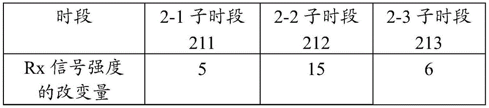
表3table 3

控制器220通过对表1到表3中示出的数据求和来确定坐标指示装置250的输入位置。如表1到表3中的数据所示,由接收电极212接收的Rx信号的强度被识别为最大的有效改变(most significantly changed)。另外,如表1到表3的数据所示,可以识别出,在第二时段里Rx信号强度的改变量与第一时段和第三时段里Rx信号强度的改变量相比更高。因此,控制器220确定与接收电极212相应的x轴坐标是坐标指示装置250的输入位置的x轴坐标。此外,控制器220确定对应于第二时段的与传送电极215相应的y轴坐标为坐标指示装置250的输入位置的y轴坐标。也就是说,控制器220确定传送电极215与接收电极212之间的交叉点为输入位置。替换地,控制器220可以通过基于表1到表3的数据的插值或各种算法来确定输入位置的坐标。The
因此,控制器220可以首先确定坐标指示装置250的输入位置。此后,控制器220确定用于触摸的物体是坐标指示装置250还是手指。坐标指示装置250可以具有特定的响应特性,其可以是坐标指示装置对于在传送电极214到216中生成的Tx信号的标识信息。在这种情况下,控制器220可以从由接收电极211到213接收的Rx信号中接收坐标指示装置的标识信息。因此,控制器220能够检测Rx信号中是否存在坐标指示装置的标识信息,从而确定触摸是否是由坐标指示装置250做出的。Therefore, the
当用户用他/她的手指执行触摸时,或者当用户用坐标指示装置执行触摸时,控制器220确定Rx信号中是否存在由坐标指示装置生成的特定的响应特性,从而可以确定触摸是由手指执行的还是坐标指示装置执行的。When the user performs touch with his/her finger, or when the user performs touch with the coordinate pointing device, the
也就是说,控制器220根据坐标指示装置的标识信息是否包括在Rx信号中来区分接触物体的类型。That is, the
替换地,控制器220能够将具有两个或更多个不同频率的信号施加到传送电极214到216。控制器220从一个频率的响应特性中确定接触物体的位置,并且从另一个频率的响应特性中确定接触物体的类型或接触压力。Alternatively,
图2B是示出根据本发明的实施例的坐标测量系统的示图。如图2B中所示,坐标测量系统包括接收电极211到213、传送电极214到216、以及控制器227,并且控制器227包括传送电极控制开关221、驱动器222、接收电极控制开关224、接收器225、MCU 226等等。2B is a diagram illustrating a coordinate measurement system according to an embodiment of the present invention. As shown in FIG. 2B , the coordinate measurement system includes receiving
驱动器222通过传送电极控制开关221向传送电极214到216提供预先设定的电信号。The
传送电极控制开关221基于预先设定的次序向传送电极214到216中的每一个提供来自驱动器222的电信号。如参考图2A所描述的,传送电极控制开关221能够,例如,在第一时段里将传送电极214连接到驱动器222,在第二时段里将传送电极215连接到驱动器222,以及在第三时段里将传送电极216连接到驱动器222。传送电极214到216能够基于接收的电信号输出Tx信号。The transmission
接收电极控制开关224基于预先设定的次序将接收电极211到213连接到接收器225。例如,接收电极控制开关224在1-1子时段里将接收电极211连接到接收器225,在1-2子时段里将接收电极212连接到接收器225,以及在1-3子时段里将接收电极213连接到接收器225。The receiving
此外,多个接收器可以在相同的时间通过多个接收电极211到213接收Rx信号而不使用接收电极控制开关。In addition, multiple receivers can receive Rx signals through multiple receive
MCU 226通过分析接收的Rx信号来确定接触物体的输入位置和类型。The
图3A是示出根据本发明的实施例的坐标指示装置的示图。FIG. 3A is a diagram illustrating a coordinate indicating device according to an embodiment of the present invention.
如图3A中所示,坐标指示装置300包括导电尖端310、共振电路单元320、和接地单元330。导电尖端310的一端连接到共振电路单元320的一端。另外,共振电路单元320的另一端可以连接到接地单元330。例如,坐标指示装置300可以以笔的形状来实现。As shown in FIG. 3A , the coordinate indicating
导电尖端310与包括在坐标测量装置(未示出)中的通道电极312形成电容313。导电尖端310可以被构造为,例如,金属尖端(metal tip),并且与坐标测量装置(未示出)的通道电极312中的至少一个形成电容313。导电尖端310可以存在于非导电性材料中,或者导电尖端310的一部分可以暴露在外面。另外,通道电极312可以被构造为在透明窗口311的较低一端中的透明电极,以便被施加到触摸屏。The
共振电路单元320能够与从坐标测量装置(未示出)接收的Tx信号共振。即使在Tx信号的输入停止之后,共振电路单元320也能够输出由于共振引起的共振信号。例如,共振电路单元320能够输出具有共振电路单元的共振频率的正弦波形信号。在这里,具有特定共振频率的正弦波形信号可以是坐标指示装置的标识信息。The
也就是说,当具有特定共振频率的正弦波形信号包括在Rx信号中时,坐标测量装置确定接触物体的类型对应于坐标指示装置。That is, when a sinusoidal waveform signal having a specific resonance frequency is included in the Rx signal, the coordinate measuring device determines that the type of the contacting object corresponds to the coordinate indicating device.
替换地,共振电路单元320的共振频率可以根据导电尖端310的接触压力而改变。例如,当用户与坐标指示装置接触时,共振电路单元320的共振频率可以改变。Alternatively, the resonance frequency of the
相应地,坐标测量装置基于共振频率的改变来确定写压力。Accordingly, the coordinate measuring device determines the write pressure based on the change in the resonance frequency.
另外,共振电路单元320还可以包括并联连接的电阻器。在这里,电阻器可以是可变电阻器,并且共振特性可以根据电阻值的改变而改变。此外,坐标指示装置还可以包括由用户机械地控制的开关单元。在坐标测量装置中,共振特性可以根据开关单元的状态而改变。因此,例如,用户基于开关单元的接通/断开状态而输入写/擦除功能。In addition, the
图3B是示出根据本发明的实施例的坐标指示装置的截面图。3B is a cross-sectional view illustrating a coordinate indicating device according to an embodiment of the present invention.
如图3B中所示,坐标指示装置包括导电尖端310、接地单元330、绝缘体340、和无源电路单元370。As shown in FIG. 3B , the coordinate indicating device includes a
导电尖端310与包括在坐标测量装置(未示出)中的电极形成电容。导电尖端310的一部分可以暴露在坐标指示装置的外部,如图3B中所示。The
此外,为了让用户在使用坐标指示装置时感觉到更加柔滑的触感,坐标指示装置还可以包括用于防止导电尖端310直接与外部接触的绝缘体。In addition, in order for the user to feel a smoother touch when using the coordinate indicating device, the coordinate indicating device may further include an insulator for preventing the
无源电路单元370被电连接到导电尖端310。无源电路单元370可以生成坐标指示装置的标识信息。也就是说,无源电路单元370可以产生不同于手指的物理特性的坐标指示装置的物理特性。在图3A中,共振电路单元已经被描述为无源电路单元370的示例。
绝缘体340将导电尖端310与接地单元330电绝缘。The
绝缘体340的形状可以变化,只要绝缘体340用作将导电尖端310与接地单元330绝缘。The shape of the
接地单元330被连接到无源电路单元370,并且能够通过直接接触和电容性耦合中的至少一个电连接到用户或坐标指示装置。The
图3C是示出根据本发明的另一个实施例的坐标指示装置的示图。如图3C中所示,坐标指示装置360包括导电尖端310、共振电路单元315、可变阻抗单元318、和接地单元330。FIG. 3C is a diagram illustrating a coordinate indicating device according to another embodiment of the present invention. As shown in FIG. 3C , the coordinate indicating
导电尖端310与包括坐标测量装置(未示出)中的电极形成电容。共振电路单元315可以电连接到导电尖端310。共振电路单元315可以生成坐标指示装置的标识信息,并且输出所生成的标识信息。也就是说,共振电路单元315可以使坐标指示装置的物理特性不同于手指的物理特性。另外,可变阻抗单元318可以由一组器件实现,所述一组器件的阻抗可以通过接触压力以及接触或不接触中的至少一个来改变。由于可变阻抗单元318提供根据接触压力和用户选择开关的接通/断开状态中的至少一个而改变的阻抗,共振特性能够根据接触压力和用户选择开关的接通/断开状态中的至少一个而改变。坐标测量装置基于改变的共振特性确定坐标指示装置的接触压力和用户选择开关的接通/断开状态中的至少一个。在这时,可变阻抗单元318的配置包括根据接触压力或用户选择开关的接通/断开状态而改变的电抗组件或电阻组件。共振电路单元315在特定的共振频率可以具有高阻抗特性。The
图3D是示出根据本发明的实施例的坐标指示装置的示图。FIG. 3D is a diagram illustrating a coordinate indicating device according to an embodiment of the present invention.
如图3D中所示,坐标指示装置包括导电尖端310、线圈单元311、电容单元312、开关单元313、和接地单元314。As shown in FIG. 3D , the coordinate indicating device includes a
导电尖端310与包括在坐标测量装置(未示出)中的电极形成电容。线圈单元311和电容单元312形成并联共振电路(parallel resonant circuit)。由于线圈单元311和电容单元312形成共振电路,则坐标指示装置输出共振信号。The
开关单元313可以被连接到线圈单元311的一端和电容单元312的一端。开关单元313可以被机械地控制。共振特性可以基于开关单元313的接通/断开状态而改变。例如,当开关单元313处于断开状态时,导电尖端310和共振电路之间的连接被断开,并且当开关单元313处于接通状态时,导电尖端310可以连接到共振电路。作为这样的配置的实施例,当以等于或大于预先设定的阈值的压力触摸导电尖端310时,开关单元313形成共振电路,而当以小于预先设定的阈值的压力触摸导电尖端310时,开关单元313可以通过断开电连接而不形成共振电路。只有当坐标指示装置以等于或大于预先设定的阈值的压力执行触摸时,该触摸才能够被辨识为输入,并且因此,有可能有效地减少由错误造成的坐标指示装置的输入。The
图3E是示出根据本发明的实施例的坐标指示装置的截面图。3E is a cross-sectional view illustrating a coordinate indicating device according to an embodiment of the present invention.
如图3E中所示,坐标指示装置包括导电尖端310、接地单元330、绝缘体340、无源电路单元370、和开关单元390。As shown in FIG. 3E , the coordinate indicating device includes a
与图3B中的坐标指示装置相比,图3E中的坐标指示装置还可以包括开关单元390。开关单元390可以电连接在导电尖端310和无源电路单元370之间。如结合图3D所描述的,开关单元390可以只在导电尖端310被以等于或大于预先设定的阈值的压力触摸时才操作共振电路。Compared with the coordinate indicating device in FIG. 3B , the coordinate indicating device in FIG. 3E may further include a
图4A到图4C是示出根据本发明的实施例的坐标指示装置识别过程的示图。4A to 4C are diagrams illustrating a coordinate indicating device identification process according to an embodiment of the present invention.
如图4A中所示,传送电极214到216输出Tx信号201。如图4A中所示,Tx信号可以是方波信号,并且具有预定时段T1和幅值(amplitude)A。在图4A中,假定坐标指示装置或手指不位于坐标测量装置附近。Rx信号202可以具有与Tx信号201的时段相同的时段T1。As shown in FIG. 4A , the
在图4B中,假定用户通过使用他/她的手指触摸电极的特定的点。如图4B中所示,Tx信号201可以是方波信号,并且具有预定时段T1和幅度A。当手指以与之前当手指被触摸(B)时的方式不同的方式被触摸(C)时,Rx信号203的幅值的大小可以改变。也就是说,Rx信号203的幅值可以从图4A中的Rx信号202的幅值(B)改变Δl。In FIG. 4B, it is assumed that the user touches a specific point of the electrode by using his/her finger. As shown in FIG. 4B , the Tx signal 201 may be a square wave signal, and has a predetermined period T1 and an amplitude A. When the finger is touched (C) in a different way than when the finger was touched (B) before, the magnitude of the amplitude of the Rx signal 203 may change. That is, the magnitude of the Rx signal 203 may vary by Δl from the magnitude (B) of the
在图4C中,假定用户通过使用坐标指示装置触摸特定的点。如图4C中所示,Tx信号201可以是方波信号,并且具有预定时段T1和幅值A。可以识别由坐标指示装置的通道电极单元的电容改变引起的Rx信号204的幅值(C)改变。也就是说,幅值可以从图4A中的Rx信号202的幅值B改变Δl。Rx信号204可以被识别为在方波的剩余时段中包括正弦波形信号。也就是说,Rx信号204包括坐标指示装置的标识信息。坐标测量装置基于在Rx信号204的方波的剩余时段中存在坐标指示装置的标识信息,确定接触物体是坐标指示装置。也就是说,坐标测量装置通过在驱动器(未示出)施加驱动信号的驱动时段期间的Rx信号确定接触物体的位置,并且通过在驱动器(未示出)不施加驱动信号的剩余时段期间的Rx信号确定接触物体的类型。In FIG. 4C, it is assumed that the user touches a specific point by using the coordinate pointing device. As shown in FIG. 4C , the Tx signal 201 may be a square wave signal, and has a predetermined period T1 and an amplitude A. A change in amplitude (C) of the Rx signal 204 caused by a change in capacitance of the channel electrode unit of the coordinate indicating device can be identified. That is, the amplitude may vary by Δl from the amplitude B of the
图4A到图4C中的方波和正弦波形只是示例。The square and sinusoidal waveforms in FIGS. 4A to 4C are examples only.
如以上描述,例如,由于共振特性根据写压力或开关单元的状态而改变,包括在来自坐标指示装置的Rx信号204中的坐标指示装置的标识信息的时段可以改变。坐标指示装置检测正弦波形的时段中的改变,并且因此确定坐标指示装置的写压力或开关单元的状态。As described above, the period of identification information of the coordinate indicating device included in the Rx signal 204 from the coordinate indicating device may vary, for example, since the resonance characteristic changes according to the writing pressure or the state of the switching unit. The coordinate indicating device detects a change in the period of the sinusoidal waveform, and thus determines the writing pressure of the coordinate indicating device or the state of the switch unit.
图5是根据本发明的另一个实施例的坐标测量系统的控制方法的流程图。FIG. 5 is a flowchart of a control method of a coordinate measuring system according to another embodiment of the present invention.
在步骤S501中,坐标测量装置的每一个传送电极基于预先设定的次序传送Tx信号。坐标测量装置可以在步骤S503中接收包括坐标指示装置的响应特性的Rx信号。在步骤S505中,坐标测量装置通过分析在Tx驱动时段期间Rx信号大小的改变来确定接触物体的输入位置,然后在步骤S507中,通过分析在Tx剩余时段期间Rx信号的频率的响应特性来区分接触物体的类型。In step S501, each transmission electrode of the coordinate measuring device transmits a Tx signal based on a preset order. The coordinate measuring device may receive the Rx signal including the response characteristic of the coordinate indicating device in step S503. In step S505, the coordinate measuring device determines the input position of the contacting object by analyzing the change in the magnitude of the Rx signal during the Tx driving period, and then in step S507, distinguishes by analyzing the response characteristics of the frequency of the Rx signal during the remaining Tx period Type of contact object.
图6是根据本发明的另一个实施例的坐标测量系统的控制方法的流程图。FIG. 6 is a flowchart of a control method of a coordinate measuring system according to another embodiment of the present invention.
在步骤S601中,坐标测量装置的每一个传送电极中基于预先设定的次序传送Tx信号。坐标测量装置可以在步骤S603中接收包括坐标指示装置的响应特性的Rx信号。In step S601, each transmission electrode of the coordinate measuring device transmits a Tx signal based on a preset order. The coordinate measuring device may receive the Rx signal including the response characteristic of the coordinate indicating device in step S603.
当Rx信号大小的改变等于或小于预先设定的阈值,例如,图4B中所示的Δl时(步骤S605中的“否”),在步骤S607中,坐标测量装置确定没有输入。When the change in the magnitude of the Rx signal is equal to or smaller than a preset threshold, eg, Δ1 shown in FIG. 4B (NO in step S605), in step S607, the coordinate measuring apparatus determines that there is no input.
当Rx信号大小的改变大于预先设定的阈值,例如,图4B中所示的Δl时(步骤S605中的“是”),在步骤S609中,坐标测量装置确定输入的坐标。When the change in the magnitude of the Rx signal is larger than a preset threshold, eg, Δ1 shown in FIG. 4B (YES in step S605 ), in step S609 , the coordinate measuring device determines the input coordinates.
在步骤S611中,坐标测量装置确定在Tx剩余时段期间Rx信号里是否存在AC波形。当Rx信号里存在AC波形时(步骤S611中的“是”),在步骤S613中,坐标测量装置确定接触物体是坐标指示装置。当Rx信号里不存在AC波形时(步骤S611中的“否”),在步骤S615中,坐标测量装置确定接触物体是手指。In step S611, the coordinate measuring apparatus determines whether there is an AC waveform in the Rx signal during the Tx remaining period. When there is an AC waveform in the Rx signal ("Yes" in step S611), in step S613, the coordinate measuring device determines that the contacting object is a coordinate indicating device. When there is no AC waveform in the Rx signal (NO in step S611), in step S615, the coordinate measuring apparatus determines that the contacting object is a finger.
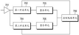
图7是用于描述根据本发明的实施例的、测量由写压力或开关的接通/断开状态引起的共振频率改变的方法的框图。7 is a block diagram for describing a method of measuring a resonant frequency change caused by a write pressure or an on/off state of a switch according to an embodiment of the present invention.
Rx信号可以由放大器701以预先设定的增益放大。第一开关单元702能够在第一时段里将放大的Rx信号输出到整合单元(integration unit)703。第二开关单元704能够在第二时段里将放大的Rx信号输出到整合单元705。The Rx signal may be amplified by the
第一时段和第二时段具有时间上重叠的部分,但是其整体部分并不彼此相同。第一开关单元702和第二开关单元704可以基于控制电路单元706中的驱动脉冲生成端在预定的时间进行接通/断开控制。另外,可以进一步引入整流器来改进接收信号的灵敏度(sensitivity)。The first period and the second period have temporally overlapping parts, but their entire parts are not identical to each other. The
控制电路单元706在第一时段和第二时段的不同部分测量频率响应特性。由于在每个部分测量的信号的比率可以根据坐标指示装置的频率响应特性而不同,控制电路单元706根据在每个部分中测量的信号的比率来确定坐标指示装置的接触压力或坐标指示装置的开关单元的接通/断开状态。The
也就是说,控制电路单元706基于相同时段的至少两个不同部分中的无源电路的响应特性来测量接触压力或开关接通/断开状态。That is, the
虽然已经参考本发明的各种实施例示出和描述了本发明,本领域技术人员将理解,可以进行各种形式和细节上的改变而不脱离由所附权利要求定义的本发明的精神和范围。Although the present invention has been shown and described with reference to various embodiments of the invention, it will be understood by those skilled in the art that various changes in form and detail may be made therein without departing from the spirit and scope of the invention as defined by the appended claims .
Claims (23)
Applications Claiming Priority (3)
| Application Number | Priority Date | Filing Date | Title |
|---|---|---|---|
| KR10-2012-0050371 | 2012-05-11 | ||
| KR1020120050371A KR102066017B1 (en) | 2012-05-11 | 2012-05-11 | Coordinate indicating apparatus and coordinate measuring apparaturs which measures input position of coordinate indicating apparatus |
| CN201310175407.3A CN103389805B (en) | 2012-05-11 | 2013-05-13 | Coordinate indicating device and coordinate measuring device for inputting position thereof |
Related Parent Applications (1)
| Application Number | Title | Priority Date | Filing Date |
|---|---|---|---|
| CN201310175407.3A Division CN103389805B (en) | 2012-05-11 | 2013-05-13 | Coordinate indicating device and coordinate measuring device for inputting position thereof |
Publications (2)
| Publication Number | Publication Date |
|---|---|
| CN107577361A CN107577361A (en) | 2018-01-12 |
| CN107577361B true CN107577361B (en) | 2020-10-20 |
Family
ID=48520684
Family Applications (2)
| Application Number | Title | Priority Date | Filing Date |
|---|---|---|---|
| CN201710800002.2A Expired - Fee Related CN107577361B (en) | 2012-05-11 | 2013-05-13 | Coordinate measuring device and method for identifying position of contact object |
| CN201310175407.3A Expired - Fee Related CN103389805B (en) | 2012-05-11 | 2013-05-13 | Coordinate indicating device and coordinate measuring device for inputting position thereof |
Family Applications After (1)
| Application Number | Title | Priority Date | Filing Date |
|---|---|---|---|
| CN201310175407.3A Expired - Fee Related CN103389805B (en) | 2012-05-11 | 2013-05-13 | Coordinate indicating device and coordinate measuring device for inputting position thereof |
Country Status (4)
| Country | Link |
|---|---|
| US (3) | US9495045B2 (en) |
| EP (2) | EP3495932B1 (en) |
| KR (1) | KR102066017B1 (en) |
| CN (2) | CN107577361B (en) |
Families Citing this family (30)
| Publication number | Priority date | Publication date | Assignee | Title |
|---|---|---|---|---|
| US20160110015A1 (en) * | 2013-05-31 | 2016-04-21 | Sharp Kabushiki Kaisha | Touch panel system and electronic device |
| US20150049052A1 (en) * | 2013-07-31 | 2015-02-19 | Broadcom Corporation | Wireless Device With Touch-Based Stylus |
| US10042446B2 (en) | 2013-08-13 | 2018-08-07 | Samsung Electronics Company, Ltd. | Interaction modes for object-device interactions |
| US10108305B2 (en) * | 2013-08-13 | 2018-10-23 | Samsung Electronics Company, Ltd. | Interaction sensing |
| US10228786B2 (en) * | 2013-08-30 | 2019-03-12 | Lg Electronics Inc. | Mobile terminal comprising stylus pen and touch panel |
| KR102108915B1 (en) * | 2013-08-30 | 2020-05-12 | 엘지전자 주식회사 | Touch panel |
| KR102201466B1 (en) * | 2014-03-28 | 2021-01-11 | 주식회사 실리콘웍스 | A touch panel comprising pen signal detection means |
| JP2015079485A (en) * | 2013-09-11 | 2015-04-23 | 株式会社リコー | Coordinate input system, coordinate input device, coordinate input method, and program |
| KR102153915B1 (en) * | 2013-11-22 | 2020-09-09 | 엘지디스플레이 주식회사 | Touch Screen Display Device with Input System |
| KR102198176B1 (en) * | 2013-12-13 | 2021-01-04 | 삼성전자주식회사 | Method for measuring frequency of touch pen and electronic apparatus thereof |
| EP2998834B1 (en) * | 2014-08-27 | 2020-01-22 | Samsung Electronics Co., Ltd. | Touch panel |
| WO2016057174A1 (en) * | 2014-10-07 | 2016-04-14 | Analog Devices, Inc. | Focused capacitive sensing |
| US10180736B2 (en) * | 2014-11-26 | 2019-01-15 | Synaptics Incorporated | Pen with inductor |
| US9946391B2 (en) * | 2014-11-26 | 2018-04-17 | Synaptics Incorporated | Sensing objects using multiple transmitter frequencies |
| US10394392B2 (en) * | 2015-01-14 | 2019-08-27 | Atmel Corporation | Object detection and scan |
| EP4345586A3 (en) * | 2015-01-19 | 2024-06-12 | Wacom Co., Ltd. | Position indicator |
| CN106066748B (en) * | 2015-04-23 | 2020-11-06 | 辛纳普蒂克斯公司 | Sensor electrode path fault diagnosis |
| KR102369723B1 (en) | 2015-06-26 | 2022-03-04 | 삼성전자주식회사 | Input device, electronic apparatus for receiving signal from the input device |
| EP3314379B1 (en) * | 2015-06-26 | 2020-05-06 | Samsung Electronics Co., Ltd. | Input device and electronic apparatus for receiving signal from the input device |
| KR102246905B1 (en) * | 2015-09-25 | 2021-04-30 | 삼성전자주식회사 | Coordinate indicating apparatus and coordinate indicating system having the same |
| KR102523154B1 (en) * | 2016-04-22 | 2023-04-21 | 삼성전자주식회사 | Display apparatus, input device and control method thereof |
| CH712735A1 (en) * | 2016-07-22 | 2018-01-31 | Tecan Trading Ag | Pipetting device with a liquid volume sensor and liquid processing system. |
| JP1594139S (en) * | 2017-05-15 | 2018-01-09 | ||
| US11609653B2 (en) | 2018-07-09 | 2023-03-21 | Hideep Inc. | Touch apparatus and touch detection method thereof |
| KR102610222B1 (en) * | 2018-07-09 | 2023-12-06 | 주식회사 하이딥 | Touch device and touch detection method thereof |
| US10817083B2 (en) | 2018-09-07 | 2020-10-27 | Microsoft Technology Licensing, Llc | Detection of pen location relative to an electronic device |
| KR102730438B1 (en) * | 2019-04-01 | 2024-11-14 | 주식회사 하이딥 | Stylus pen |
| KR102820721B1 (en) | 2019-04-10 | 2025-06-13 | 주식회사 하이딥 | Touch apparatus and touch detection method thereof |
| CN111208917B (en) * | 2019-12-31 | 2022-04-08 | 广州视源电子科技股份有限公司 | Touch data processing method, device, smart device and storage medium |
| CN111290666B (en) * | 2020-05-13 | 2023-05-26 | 深圳市汇顶科技股份有限公司 | Signal detection method and device and touch chip |
Citations (8)
| Publication number | Priority date | Publication date | Assignee | Title |
|---|---|---|---|---|
| US5661269A (en) * | 1994-02-03 | 1997-08-26 | Wacom Co., Ltd. | Position pointing device having resonant circuit with sequentially changed characteristics and combination thereof with position detecting device |
| CN1728065A (en) * | 2004-07-27 | 2006-02-01 | 株式会社华科姆 | Position detection device and input system |
| US20070085836A1 (en) * | 2003-08-26 | 2007-04-19 | David Ely | Digitiser system |
| CN1327323C (en) * | 2002-06-07 | 2007-07-18 | 皇家飞利浦电子股份有限公司 | Input system |
| WO2008079712A1 (en) * | 2006-12-20 | 2008-07-03 | 3M Innovative Properties Company | Untethered device employing tunable resonant circuit |
| CN101470554A (en) * | 2007-12-29 | 2009-07-01 | 洋华光电股份有限公司 | Duplex touch control panel |
| CN102073423A (en) * | 2009-11-24 | 2011-05-25 | 三星移动显示器株式会社 | Touch screen and method of driving the same |
| CN102109923A (en) * | 2009-12-25 | 2011-06-29 | 株式会社和冠 | Pointing member, position detection apparatus and position detection method |
Family Cites Families (58)
| Publication number | Priority date | Publication date | Assignee | Title |
|---|---|---|---|---|
| US5543590A (en) * | 1992-06-08 | 1996-08-06 | Synaptics, Incorporated | Object position detector with edge motion feature |
| US5488204A (en) * | 1992-06-08 | 1996-01-30 | Synaptics, Incorporated | Paintbrush stylus for capacitive touch sensor pad |
| JP3072540B2 (en) * | 1993-02-25 | 2000-07-31 | ぺんてる株式会社 | Coordinate detection device |
| US5422959A (en) * | 1993-06-25 | 1995-06-06 | Lee; Michael E. | Signature verification apparatus and method utilizing relative angle measurements |
| US5571997A (en) * | 1993-08-02 | 1996-11-05 | Kurta Corporation | Pressure sensitive pointing device for transmitting signals to a tablet |
| JP3135183B2 (en) * | 1993-10-29 | 2001-02-13 | 株式会社ワコム | Position indicator |
| JP3421416B2 (en) * | 1994-03-18 | 2003-06-30 | 株式会社ワコム | Position detecting device and its position indicator |
| JP3510318B2 (en) * | 1994-04-28 | 2004-03-29 | 株式会社ワコム | Angle information input device |
| TW274598B (en) * | 1994-11-15 | 1996-04-21 | Alps Electric Co Ltd | Coordinate input device for pen of finger tip |
| US6236740B1 (en) * | 1995-04-07 | 2001-05-22 | Michael E. Lee | Signature verification apparatus and method utilizing relative angle measurements |
| US5672808A (en) * | 1996-06-11 | 1997-09-30 | Moore Products Co. | Transducer having redundant pressure sensors |
| DE19623468A1 (en) * | 1996-06-12 | 1997-12-18 | Wacom Co Ltd | Position detecting tablet |
| JP3394187B2 (en) * | 1997-08-08 | 2003-04-07 | シャープ株式会社 | Coordinate input device and display integrated type coordinate input device |
| US6515654B1 (en) * | 2000-10-13 | 2003-02-04 | Taiwan Regular Electronics | Touch-type pointing device with wireless input capability |
| EP1412912B1 (en) * | 2001-05-21 | 2008-06-18 | Synaptics (UK) Limited | Position sensor |
| US20030095115A1 (en) * | 2001-11-22 | 2003-05-22 | Taylor Brian | Stylus input device utilizing a permanent magnet |
| EP2388770A1 (en) | 2002-08-29 | 2011-11-23 | N-Trig Ltd. | Digitizer stylus |
| KR100459230B1 (en) * | 2002-11-14 | 2004-12-03 | 엘지.필립스 엘시디 주식회사 | touch panel for display device |
| KR100480823B1 (en) * | 2002-11-14 | 2005-04-07 | 엘지.필립스 엘시디 주식회사 | touch panel for display device |
| US7755616B2 (en) * | 2003-03-28 | 2010-07-13 | Lg Display Co., Ltd. | Liquid crystal display device having electromagnetic type touch panel |
| US7528825B2 (en) * | 2003-12-08 | 2009-05-05 | Fujitsu Component Limited | Input pen and input device |
| JP4547000B2 (en) * | 2004-04-01 | 2010-09-22 | 株式会社ワコム | Panel and cordless transducer system |
| TW200628759A (en) * | 2004-12-01 | 2006-08-16 | N trig ltd | Position detecting system and apparatuses and methods for use and control thereof |
| TWI319538B (en) * | 2006-03-22 | 2010-01-11 | Quanta Comp Inc | Screen control system |
| CN101192260B (en) * | 2006-11-24 | 2012-08-22 | 鸿富锦精密工业(深圳)有限公司 | Electronic device and method for opening same |
| KR101295356B1 (en) | 2007-08-16 | 2013-08-16 | 에스케이플래닛 주식회사 | Digitizer pen hanving a function of generating tactile feeling and system for driving the digitizer pen |
| WO2009040815A1 (en) * | 2007-09-26 | 2009-04-02 | N-Trig Ltd. | Method for identifying changes in signal frequencies emitted by a stylus interacting with a digitizer sensor |
| US8059103B2 (en) * | 2007-11-21 | 2011-11-15 | 3M Innovative Properties Company | System and method for determining touch positions based on position-dependent electrical charges |
| US8508920B2 (en) * | 2007-11-23 | 2013-08-13 | Creator Technology B.V. | Electronic apparatus with improved functionality |
| US8482545B2 (en) * | 2008-10-02 | 2013-07-09 | Wacom Co., Ltd. | Combination touch and transducer input system and method |
| DE102009046177A1 (en) * | 2008-10-30 | 2010-06-10 | Samsung Electronics Co., Ltd., Suwon | Touch data generator |
| GB2466566B (en) * | 2008-12-22 | 2010-12-22 | N trig ltd | Digitizer, stylus and method of synchronization therewith |
| CN101539816B (en) | 2009-04-16 | 2012-10-17 | 台均科技(深圳)有限公司 | Electromagnetic pen, electromagnetic signal processing method, device and equipment |
| JP5451181B2 (en) * | 2009-05-25 | 2014-03-26 | 株式会社ジャパンディスプレイ | Sensor device for detecting contact or proximity of an object |
| US20100328249A1 (en) * | 2009-06-25 | 2010-12-30 | Stmicroelecronics Asia Pacific Pte Ltd. | Capacitive-inductive touch screen |
| US9753586B2 (en) * | 2009-10-08 | 2017-09-05 | 3M Innovative Properties Company | Multi-touch touch device with multiple drive frequencies and maximum likelihood estimation |
| US8773366B2 (en) * | 2009-11-16 | 2014-07-08 | 3M Innovative Properties Company | Touch sensitive device using threshold voltage signal |
| TW201128508A (en) * | 2010-02-09 | 2011-08-16 | Waltop Int Corp | Electromagnetic inductive system with multi-signals and processing method for multi-signal |
| JP5427070B2 (en) * | 2010-03-05 | 2014-02-26 | 株式会社ワコム | Position detection device |
| US9244569B2 (en) * | 2010-03-31 | 2016-01-26 | Stmicroelectronics Asia Pacific Pte Ltd | Capacitive sensing analog front end |
| US9176630B2 (en) * | 2010-08-30 | 2015-11-03 | Perceptive Pixel, Inc. | Localizing an electrostatic stylus within a capacitive touch sensor |
| US9823785B2 (en) * | 2010-09-09 | 2017-11-21 | 3M Innovative Properties Company | Touch sensitive device with stylus support |
| US9389724B2 (en) * | 2010-09-09 | 2016-07-12 | 3M Innovative Properties Company | Touch sensitive device with stylus support |
| US10019119B2 (en) * | 2010-09-09 | 2018-07-10 | 3M Innovative Properties Company | Touch sensitive device with stylus support |
| WO2012039837A1 (en) | 2010-09-22 | 2012-03-29 | Cypress Semiconductor Corporation | Capacitive stylus for a touch screen |
| JP5839173B2 (en) * | 2010-10-14 | 2016-01-06 | Nltテクノロジー株式会社 | Touch sensor device and electronic device |
| WO2012057888A1 (en) * | 2010-10-28 | 2012-05-03 | Cypress Semiconductor Corporation | Synchronizing a stylus with a capacitive sense array |
| US9299337B2 (en) | 2011-01-11 | 2016-03-29 | Bose Corporation | Vehicle engine sound enhancement |
| TWI416375B (en) * | 2011-01-21 | 2013-11-21 | Sunrex Technology Corp | Position detection device |
| US20120327040A1 (en) * | 2011-06-22 | 2012-12-27 | Simon David I | Identifiable stylus |
| EP2725464A4 (en) * | 2011-06-27 | 2015-03-11 | Actions Semiconductor Co Ltd | Method and apparatus for detecting resistive touch panel |
| US10725564B2 (en) * | 2011-10-28 | 2020-07-28 | Wacom Co., Ltd. | Differential sensing in an active stylus |
| US20130207926A1 (en) | 2012-02-15 | 2013-08-15 | Viktor Kremin | Stylus to host synchronization |
| KR20130107473A (en) * | 2012-03-22 | 2013-10-02 | 삼성전자주식회사 | Capactive type touch pen |
| JP5984259B2 (en) | 2012-09-20 | 2016-09-06 | 株式会社ワコム | Position detection device |
| US9213455B2 (en) * | 2012-10-17 | 2015-12-15 | Atmel Corporation | Stylus with resonant circuit |
| US20140204038A1 (en) * | 2013-01-21 | 2014-07-24 | Kabushiki Kaisha Toshiba | Information apparatus and information processing method |
| US20140267184A1 (en) * | 2013-03-14 | 2014-09-18 | Elwha Llc | Multimode Stylus |
-
2012
- 2012-05-11 KR KR1020120050371A patent/KR102066017B1/en not_active Expired - Fee Related
-
2013
- 2013-04-05 US US13/857,713 patent/US9495045B2/en active Active
- 2013-05-13 CN CN201710800002.2A patent/CN107577361B/en not_active Expired - Fee Related
- 2013-05-13 CN CN201310175407.3A patent/CN103389805B/en not_active Expired - Fee Related
- 2013-05-13 EP EP18208811.2A patent/EP3495932B1/en active Active
- 2013-05-13 EP EP13167456.6A patent/EP2662759B1/en active Active
-
2016
- 2016-10-19 US US15/297,695 patent/US10261623B2/en active Active
-
2019
- 2019-03-12 US US16/299,789 patent/US10754468B2/en active Active
Patent Citations (8)
| Publication number | Priority date | Publication date | Assignee | Title |
|---|---|---|---|---|
| US5661269A (en) * | 1994-02-03 | 1997-08-26 | Wacom Co., Ltd. | Position pointing device having resonant circuit with sequentially changed characteristics and combination thereof with position detecting device |
| CN1327323C (en) * | 2002-06-07 | 2007-07-18 | 皇家飞利浦电子股份有限公司 | Input system |
| US20070085836A1 (en) * | 2003-08-26 | 2007-04-19 | David Ely | Digitiser system |
| CN1728065A (en) * | 2004-07-27 | 2006-02-01 | 株式会社华科姆 | Position detection device and input system |
| WO2008079712A1 (en) * | 2006-12-20 | 2008-07-03 | 3M Innovative Properties Company | Untethered device employing tunable resonant circuit |
| CN101470554A (en) * | 2007-12-29 | 2009-07-01 | 洋华光电股份有限公司 | Duplex touch control panel |
| CN102073423A (en) * | 2009-11-24 | 2011-05-25 | 三星移动显示器株式会社 | Touch screen and method of driving the same |
| CN102109923A (en) * | 2009-12-25 | 2011-06-29 | 株式会社和冠 | Pointing member, position detection apparatus and position detection method |
Also Published As
| Publication number | Publication date |
|---|---|
| EP2662759A3 (en) | 2016-04-06 |
| US20190204986A1 (en) | 2019-07-04 |
| EP3495932A2 (en) | 2019-06-12 |
| US9495045B2 (en) | 2016-11-15 |
| CN107577361A (en) | 2018-01-12 |
| CN103389805A (en) | 2013-11-13 |
| CN103389805B (en) | 2017-09-22 |
| US10261623B2 (en) | 2019-04-16 |
| US20170038901A1 (en) | 2017-02-09 |
| EP2662759A2 (en) | 2013-11-13 |
| KR102066017B1 (en) | 2020-01-14 |
| US20130300708A1 (en) | 2013-11-14 |
| EP3495932B1 (en) | 2021-11-10 |
| US10754468B2 (en) | 2020-08-25 |
| EP2662759B1 (en) | 2018-12-12 |
| KR20130127033A (en) | 2013-11-22 |
| EP3495932A3 (en) | 2019-07-10 |
Similar Documents
| Publication | Publication Date | Title |
|---|---|---|
| CN107577361B (en) | Coordinate measuring device and method for identifying position of contact object | |
| EP3035168B1 (en) | Pen input device, method for correcting input coordinate thereof and electronic device for supporting the same | |
| CN103389804B (en) | Coordinate instruction equipment and the coordinate measurment instrument for measuring its input position | |
| CN104516549B (en) | Touch-sensing system and its driving method | |
| KR102125404B1 (en) | Touch sensing system and diplay device | |
| US10379666B2 (en) | Position measuring apparatus, pen and position measuring method | |
| US20150070297A1 (en) | Control method for touch panel | |
| KR20160025440A (en) | Touch penel and coordinate indicating system having the same | |
| JP2013152581A (en) | Detector, detection method and display device | |
| US11995262B2 (en) | Touch apparatus and touch detection method thereof | |
| KR20230165742A (en) | Touch device and touch detection method thereof | |
| CN103853407B (en) | The multi-point touch haptic device of multi-frequency and barycenter capacitance detecting | |
| CN110869898B (en) | Multi-capacitance pen identification method, touch control unit, touch panel and system | |
| KR102131310B1 (en) | Coordinate indicating apparatus and coordinate measuring apparatus which measures input position of coordinate indicating apparatus |
Legal Events
| Date | Code | Title | Description |
|---|---|---|---|
| PB01 | Publication | ||
| PB01 | Publication | ||
| SE01 | Entry into force of request for substantive examination | ||
| SE01 | Entry into force of request for substantive examination | ||
| GR01 | Patent grant | ||
| GR01 | Patent grant | ||
| CF01 | Termination of patent right due to non-payment of annual fee |
Granted publication date: 20201020 |
|
| CF01 | Termination of patent right due to non-payment of annual fee |