CN107329301B - display device - Google Patents
display device Download PDFInfo
- Publication number
- CN107329301B CN107329301B CN201610279365.1A CN201610279365A CN107329301B CN 107329301 B CN107329301 B CN 107329301B CN 201610279365 A CN201610279365 A CN 201610279365A CN 107329301 B CN107329301 B CN 107329301B
- Authority
- CN
- China
- Prior art keywords
- arc
- shaped fixing
- display device
- light
- optical
- Prior art date
- Legal status (The legal status is an assumption and is not a legal conclusion. Google has not performed a legal analysis and makes no representation as to the accuracy of the status listed.)
- Active
Links
Images


Classifications
-
- G—PHYSICS
- G02—OPTICS
- G02F—OPTICAL DEVICES OR ARRANGEMENTS FOR THE CONTROL OF LIGHT BY MODIFICATION OF THE OPTICAL PROPERTIES OF THE MEDIA OF THE ELEMENTS INVOLVED THEREIN; NON-LINEAR OPTICS; FREQUENCY-CHANGING OF LIGHT; OPTICAL LOGIC ELEMENTS; OPTICAL ANALOGUE/DIGITAL CONVERTERS
- G02F1/00—Devices or arrangements for the control of the intensity, colour, phase, polarisation or direction of light arriving from an independent light source, e.g. switching, gating or modulating; Non-linear optics
- G02F1/01—Devices or arrangements for the control of the intensity, colour, phase, polarisation or direction of light arriving from an independent light source, e.g. switching, gating or modulating; Non-linear optics for the control of the intensity, phase, polarisation or colour
- G02F1/13—Devices or arrangements for the control of the intensity, colour, phase, polarisation or direction of light arriving from an independent light source, e.g. switching, gating or modulating; Non-linear optics for the control of the intensity, phase, polarisation or colour based on liquid crystals, e.g. single liquid crystal display cells
- G02F1/133—Constructional arrangements; Operation of liquid crystal cells; Circuit arrangements
- G02F1/1333—Constructional arrangements; Manufacturing methods
- G02F1/1335—Structural association of cells with optical devices, e.g. polarisers or reflectors
- G02F1/1336—Illuminating devices
- G02F1/133602—Direct backlight
- G02F1/133605—Direct backlight including specially adapted reflectors
-
- G—PHYSICS
- G02—OPTICS
- G02F—OPTICAL DEVICES OR ARRANGEMENTS FOR THE CONTROL OF LIGHT BY MODIFICATION OF THE OPTICAL PROPERTIES OF THE MEDIA OF THE ELEMENTS INVOLVED THEREIN; NON-LINEAR OPTICS; FREQUENCY-CHANGING OF LIGHT; OPTICAL LOGIC ELEMENTS; OPTICAL ANALOGUE/DIGITAL CONVERTERS
- G02F1/00—Devices or arrangements for the control of the intensity, colour, phase, polarisation or direction of light arriving from an independent light source, e.g. switching, gating or modulating; Non-linear optics
- G02F1/01—Devices or arrangements for the control of the intensity, colour, phase, polarisation or direction of light arriving from an independent light source, e.g. switching, gating or modulating; Non-linear optics for the control of the intensity, phase, polarisation or colour
- G02F1/13—Devices or arrangements for the control of the intensity, colour, phase, polarisation or direction of light arriving from an independent light source, e.g. switching, gating or modulating; Non-linear optics for the control of the intensity, phase, polarisation or colour based on liquid crystals, e.g. single liquid crystal display cells
- G02F1/133—Constructional arrangements; Operation of liquid crystal cells; Circuit arrangements
- G02F1/1333—Constructional arrangements; Manufacturing methods
- G02F1/133305—Flexible substrates, e.g. plastics, organic film
-
- G—PHYSICS
- G02—OPTICS
- G02F—OPTICAL DEVICES OR ARRANGEMENTS FOR THE CONTROL OF LIGHT BY MODIFICATION OF THE OPTICAL PROPERTIES OF THE MEDIA OF THE ELEMENTS INVOLVED THEREIN; NON-LINEAR OPTICS; FREQUENCY-CHANGING OF LIGHT; OPTICAL LOGIC ELEMENTS; OPTICAL ANALOGUE/DIGITAL CONVERTERS
- G02F1/00—Devices or arrangements for the control of the intensity, colour, phase, polarisation or direction of light arriving from an independent light source, e.g. switching, gating or modulating; Non-linear optics
- G02F1/01—Devices or arrangements for the control of the intensity, colour, phase, polarisation or direction of light arriving from an independent light source, e.g. switching, gating or modulating; Non-linear optics for the control of the intensity, phase, polarisation or colour
- G02F1/13—Devices or arrangements for the control of the intensity, colour, phase, polarisation or direction of light arriving from an independent light source, e.g. switching, gating or modulating; Non-linear optics for the control of the intensity, phase, polarisation or colour based on liquid crystals, e.g. single liquid crystal display cells
- G02F1/133—Constructional arrangements; Operation of liquid crystal cells; Circuit arrangements
- G02F1/1333—Constructional arrangements; Manufacturing methods
- G02F1/133308—Support structures for LCD panels, e.g. frames or bezels
-
- G—PHYSICS
- G02—OPTICS
- G02F—OPTICAL DEVICES OR ARRANGEMENTS FOR THE CONTROL OF LIGHT BY MODIFICATION OF THE OPTICAL PROPERTIES OF THE MEDIA OF THE ELEMENTS INVOLVED THEREIN; NON-LINEAR OPTICS; FREQUENCY-CHANGING OF LIGHT; OPTICAL LOGIC ELEMENTS; OPTICAL ANALOGUE/DIGITAL CONVERTERS
- G02F1/00—Devices or arrangements for the control of the intensity, colour, phase, polarisation or direction of light arriving from an independent light source, e.g. switching, gating or modulating; Non-linear optics
- G02F1/01—Devices or arrangements for the control of the intensity, colour, phase, polarisation or direction of light arriving from an independent light source, e.g. switching, gating or modulating; Non-linear optics for the control of the intensity, phase, polarisation or colour
- G02F1/13—Devices or arrangements for the control of the intensity, colour, phase, polarisation or direction of light arriving from an independent light source, e.g. switching, gating or modulating; Non-linear optics for the control of the intensity, phase, polarisation or colour based on liquid crystals, e.g. single liquid crystal display cells
- G02F1/133—Constructional arrangements; Operation of liquid crystal cells; Circuit arrangements
- G02F1/1333—Constructional arrangements; Manufacturing methods
- G02F1/13338—Input devices, e.g. touch panels
-
- G—PHYSICS
- G02—OPTICS
- G02F—OPTICAL DEVICES OR ARRANGEMENTS FOR THE CONTROL OF LIGHT BY MODIFICATION OF THE OPTICAL PROPERTIES OF THE MEDIA OF THE ELEMENTS INVOLVED THEREIN; NON-LINEAR OPTICS; FREQUENCY-CHANGING OF LIGHT; OPTICAL LOGIC ELEMENTS; OPTICAL ANALOGUE/DIGITAL CONVERTERS
- G02F1/00—Devices or arrangements for the control of the intensity, colour, phase, polarisation or direction of light arriving from an independent light source, e.g. switching, gating or modulating; Non-linear optics
- G02F1/01—Devices or arrangements for the control of the intensity, colour, phase, polarisation or direction of light arriving from an independent light source, e.g. switching, gating or modulating; Non-linear optics for the control of the intensity, phase, polarisation or colour
- G02F1/13—Devices or arrangements for the control of the intensity, colour, phase, polarisation or direction of light arriving from an independent light source, e.g. switching, gating or modulating; Non-linear optics for the control of the intensity, phase, polarisation or colour based on liquid crystals, e.g. single liquid crystal display cells
- G02F1/133—Constructional arrangements; Operation of liquid crystal cells; Circuit arrangements
- G02F1/1333—Constructional arrangements; Manufacturing methods
- G02F1/1335—Structural association of cells with optical devices, e.g. polarisers or reflectors
- G02F1/1336—Illuminating devices
- G02F1/133602—Direct backlight
- G02F1/133608—Direct backlight including particular frames or supporting means
-
- G—PHYSICS
- G02—OPTICS
- G02F—OPTICAL DEVICES OR ARRANGEMENTS FOR THE CONTROL OF LIGHT BY MODIFICATION OF THE OPTICAL PROPERTIES OF THE MEDIA OF THE ELEMENTS INVOLVED THEREIN; NON-LINEAR OPTICS; FREQUENCY-CHANGING OF LIGHT; OPTICAL LOGIC ELEMENTS; OPTICAL ANALOGUE/DIGITAL CONVERTERS
- G02F1/00—Devices or arrangements for the control of the intensity, colour, phase, polarisation or direction of light arriving from an independent light source, e.g. switching, gating or modulating; Non-linear optics
- G02F1/01—Devices or arrangements for the control of the intensity, colour, phase, polarisation or direction of light arriving from an independent light source, e.g. switching, gating or modulating; Non-linear optics for the control of the intensity, phase, polarisation or colour
- G02F1/13—Devices or arrangements for the control of the intensity, colour, phase, polarisation or direction of light arriving from an independent light source, e.g. switching, gating or modulating; Non-linear optics for the control of the intensity, phase, polarisation or colour based on liquid crystals, e.g. single liquid crystal display cells
- G02F1/133—Constructional arrangements; Operation of liquid crystal cells; Circuit arrangements
- G02F1/1333—Constructional arrangements; Manufacturing methods
- G02F1/133308—Support structures for LCD panels, e.g. frames or bezels
- G02F1/133314—Back frames
-
- G—PHYSICS
- G02—OPTICS
- G02F—OPTICAL DEVICES OR ARRANGEMENTS FOR THE CONTROL OF LIGHT BY MODIFICATION OF THE OPTICAL PROPERTIES OF THE MEDIA OF THE ELEMENTS INVOLVED THEREIN; NON-LINEAR OPTICS; FREQUENCY-CHANGING OF LIGHT; OPTICAL LOGIC ELEMENTS; OPTICAL ANALOGUE/DIGITAL CONVERTERS
- G02F1/00—Devices or arrangements for the control of the intensity, colour, phase, polarisation or direction of light arriving from an independent light source, e.g. switching, gating or modulating; Non-linear optics
- G02F1/01—Devices or arrangements for the control of the intensity, colour, phase, polarisation or direction of light arriving from an independent light source, e.g. switching, gating or modulating; Non-linear optics for the control of the intensity, phase, polarisation or colour
- G02F1/13—Devices or arrangements for the control of the intensity, colour, phase, polarisation or direction of light arriving from an independent light source, e.g. switching, gating or modulating; Non-linear optics for the control of the intensity, phase, polarisation or colour based on liquid crystals, e.g. single liquid crystal display cells
- G02F1/133—Constructional arrangements; Operation of liquid crystal cells; Circuit arrangements
- G02F1/1333—Constructional arrangements; Manufacturing methods
- G02F1/133308—Support structures for LCD panels, e.g. frames or bezels
- G02F1/13332—Front frames
Landscapes
- Physics & Mathematics (AREA)
- Nonlinear Science (AREA)
- Mathematical Physics (AREA)
- Chemical & Material Sciences (AREA)
- Crystallography & Structural Chemistry (AREA)
- General Physics & Mathematics (AREA)
- Optics & Photonics (AREA)
- Liquid Crystal (AREA)
- Devices For Indicating Variable Information By Combining Individual Elements (AREA)
Abstract
本发明提供一种显示装置。显示装置包括一第一弧形固定件、一第二弧形固定件、一光学元件、一光学膜片组以及一显示面板。第二弧形固定件与第一弧形固定件对应设置,且第二弧形固定件连接于第一弧形固定件的外缘。光学元件夹置于第一弧形固定件与第二弧形固定件之间而形成一曲面。光学膜片组与光学元件相邻设置。显示面板与第二弧形固定件对应设置,并设置于第二弧形固定件远离光学元件的一侧。相较于已知显示装置具有许多构件而且组装繁琐而言,本发明的显示装置具有支撑构件较少、组装较容易的优点。
The present invention provides a display device. The display device includes a first arc-shaped fixing member, a second arc-shaped fixing member, an optical element, an optical film group and a display panel. The second arc-shaped fixing member is arranged corresponding to the first arc-shaped fixing member, and the second arc-shaped fixing member is connected to the outer edge of the first arc-shaped fixing member. The optical element is sandwiched between the first arc-shaped fixing member and the second arc-shaped fixing member to form a curved surface. The optical film group is arranged adjacent to the optical element. The display panel is arranged corresponding to the second arc-shaped fixing member and is arranged on a side of the second arc-shaped fixing member away from the optical element. Compared with the known display device having many components and complicated assembly, the display device of the present invention has the advantages of fewer supporting components and easier assembly.
Description
技术领域technical field
本发明关于一种显示装置,特别关于一种曲面的显示装置。The present invention relates to a display device, in particular to a curved display device.
背景技术Background technique
随着科技的进步,平面显示装置已经广泛的被运用在各种领域,尤其是液晶显示装置,因具有体型轻薄、低功率消耗及无辐射等优越特性,已经渐渐地取代传统阴极射线管显示装置,而应用至许多种类的电子产品中,例如移动电话、可携式多媒体装置、笔记本电脑、液晶电视及液晶荧幕等等。With the advancement of science and technology, flat-panel display devices have been widely used in various fields, especially liquid crystal display devices, which have gradually replaced traditional cathode ray tube display devices due to their superior characteristics such as thin body, low power consumption and no radiation. , and applied to many types of electronic products, such as mobile phones, portable multimedia devices, notebook computers, LCD TVs and LCD screens, etc.
为因应不同消费者的各种需求,各家业者不停地研发新的显示装置,以满足不同消费者的不同需求。其中,有业界提出了曲面显示装置的构想,曲面显示装置一般认为全画面各点至眼球距离相当,故可使观看者取得包围感较佳的全视角视野。In response to various needs of different consumers, various manufacturers are constantly developing new display devices to meet the different needs of different consumers. Among them, the concept of a curved display device has been proposed in the industry, and the curved display device generally considers that the distance from each point of the whole screen to the eyeball is equal, so that the viewer can obtain a full-view field of view with a better sense of surround.
已知一种曲面显示装置是利用曲面支架及至少一片弧形框架组成一背板结构,以将显示面板固定在背板结构上而呈现预设的弯曲状态。其中,可利用固定元件将单片弧形框架锁附在曲面支架上;亦可使用多个片小尺寸的弧形框架以部分叠合方式相连接而固定在曲面支架上。其中,弧形框架可提供背板结构的主要强度,曲面支架则提供辅助的局部补强强度。In a known curved display device, a curved support and at least one arc-shaped frame are used to form a backplane structure, so as to fix the display panel on the backplane structure to present a preset curved state. Wherein, a single piece of arc-shaped frame can be locked and attached to the curved support by using a fixing element; a plurality of small-sized arc-shaped frames can also be used to be connected in a partial overlapping manner to be fixed on the curved support. Among them, the arc frame can provide the main strength of the back plate structure, and the curved bracket can provide auxiliary local reinforcement strength.
另有利用弯曲托架以及多个固定件组成背板结构来固定显示面板,使其呈现预设的弯曲状态。其中,固定件在显示面板的平面背板上施加外力,使平面背板产生结构变形而贴附在弯曲托架上。弯曲托架可用来提供曲型支撑结构和曲面显示装置的主要强度。In addition, a curved bracket and a plurality of fixing parts are used to form a backplane structure to fix the display panel so that it presents a preset curved state. Wherein, the fixing member exerts an external force on the flat backplane of the display panel, so that the flat backplane is structurally deformed and attached to the curved bracket. A flex bracket can be used to provide the primary strength of a curved support structure and curved display device.
然而,已知曲面显示装置的背板结构大部分是由许多构件(例如曲面支架及至少一片弧形框架、弯曲托架及多个固定件)组合而成,不仅构件数量相当多,其组装过程亦相对复杂。再者,背板结构的构件一般是由冲压成型或弯管加工技术制成,但冲压成型制作成弧形构件时,会有回弹与精度控制不易的问题,而使用弯管加工技术制作的弯曲托架虽有制作方式较简单的优点,但组合后的精度却有控制不易的缺点。However, most of the backplane structure of the known curved display device is composed of many components (such as a curved bracket and at least one arc-shaped frame, a curved bracket and a plurality of fixing parts), not only the number of components is quite large, but also the assembly process Also relatively complex. In addition, the components of the back plate structure are generally made by stamping or bending technology, but when stamping and forming into an arc-shaped component, there will be problems of springback and difficult precision control, and the bending technology is used. Although the bending bracket has the advantage of being relatively simple to manufacture, the combined precision has the disadvantage of being difficult to control.
发明内容SUMMARY OF THE INVENTION
本发明的目的为提供一种新型态的曲面显示装置。本发明的显示装置具有支撑构件较少、组装较容易的优点。The purpose of the present invention is to provide a new type of curved display device. The display device of the present invention has the advantages of fewer supporting members and easier assembly.
本发明提供一种显示装置,包括一第一弧形固定件、一第二弧形固定件、一光学元件、一光学膜片组以及一显示面板。第二弧形固定件与第一弧形固定件对应设置,且第二弧形固定件连接于第一弧形固定件的外缘。光学元件夹置于第一弧形固定件与第二弧形固定件之间而形成一曲面。光学膜片组与光学元件相邻设置。显示面板与第二弧形固定件对应设置,并设置于第二弧形固定件远离光学元件的一侧。The invention provides a display device, comprising a first arc-shaped fixing member, a second arc-shaped fixing member, an optical element, an optical film group and a display panel. The second arc-shaped fixing member is arranged corresponding to the first arc-shaped fixing member, and the second arc-shaped fixing member is connected to the outer edge of the first arc-shaped fixing member. The optical element is sandwiched between the first arc-shaped fixing member and the second arc-shaped fixing member to form a curved surface. The optical film set is arranged adjacent to the optical element. The display panel is arranged corresponding to the second arc-shaped fixing member, and is arranged on the side of the second arc-shaped fixing member away from the optical element.
在一实施例中,光学元件为扩散板或导光板,且光学元件的外侧周缘夹置于第一弧形固定件与第二弧形固定件之间。In one embodiment, the optical element is a diffuser plate or a light guide plate, and the outer peripheral edge of the optical element is sandwiched between the first arc-shaped fixing member and the second arc-shaped fixing member.
在一实施例中,光学膜片组包含一第一光学膜片与一第二光学膜片,第一光学膜片设置于光学元件与第二光学膜片之间。In one embodiment, the optical film set includes a first optical film and a second optical film, and the first optical film is disposed between the optical element and the second optical film.
在一实施例中,显示装置为外凸型时,第一光学膜片平放时的长度小于或等于第二光学膜片平放时的长度。In one embodiment, when the display device is an outwardly convex type, the length of the first optical film when laid flat is less than or equal to the length of the second optical film when laid flat.
在一实施例中,显示装置为内凹型时,第一光学膜片平放时的长度大于或等于第二光学膜片平放时的长度。In one embodiment, when the display device is a concave type, the length of the first optical film when laid flat is greater than or equal to the length of the second optical film when laid flat.
在一实施例中,显示装置更包括一发光单元,发光单元设置于光学元件与第一弧形固定件之间,发光单元具有一基板及多个发光元件,该些发光元件设置于基板上,第一弧形固定件具有一内侧底面,基板设置于内侧底面上。In one embodiment, the display device further includes a light-emitting unit, the light-emitting unit is disposed between the optical element and the first arc-shaped fixing member, the light-emitting unit has a substrate and a plurality of light-emitting elements, and the light-emitting elements are disposed on the substrate, The first arc-shaped fixing member has an inner bottom surface, and the base plate is arranged on the inner bottom surface.
在一实施例中,显示装置更包括一反射片,反射片具有多个开孔,该些开孔与该些发光元件分别对应设置,该些发光元件分别穿过该些开孔而使反射片设置于基板上。In one embodiment, the display device further includes a reflection sheet, the reflection sheet has a plurality of openings, the openings are respectively corresponding to the light-emitting elements, and the light-emitting elements pass through the openings respectively to make the reflection sheet arranged on the substrate.
在一实施例中,反射片为单片式的立体反射片。In one embodiment, the reflection sheet is a monolithic three-dimensional reflection sheet.
在一实施例中,显示装置更包括一发光单元及一反射片,光学元件具有一入光面及与入光面连接的一出光面,出光面面向光学膜片组,发光单元邻设于入光面。反射片设置于光学元件与第一弧形固定件之间。In one embodiment, the display device further includes a light-emitting unit and a reflective sheet, the optical element has a light-incident surface and a light-emitting surface connected to the light-incident surface, the light-emitting surface faces the optical film set, and the light-emitting unit is adjacent to the light-emitting unit. glossy. The reflection sheet is arranged between the optical element and the first arc-shaped fixing member.
在一实施例中,显示装置更包括一触控面板,触控面板与显示面板相对而设,并设置于该显示面板远离该光学元件的一侧。In one embodiment, the display device further includes a touch panel, and the touch panel is disposed opposite to the display panel and disposed on a side of the display panel away from the optical element.
承上所述,在本发明的显示装置中,通过第二弧形固定件连接于第一弧形固定件的外缘,并使光学元件夹置于第一弧形固定件与第二弧形固定件之间而形成一曲面,另外,再通过光学膜片组与光学元件相邻设置,且显示面板与第二弧形固定件对应设置,并设置于第二弧形固定件远离光学元件的一侧,藉此,相较于已知显示装置具有许多构件而且组装繁琐而言,本发明的显示装置具有支撑构件较少、组装较容易的优点。Based on the above, in the display device of the present invention, the second arc-shaped fixing member is connected to the outer edge of the first arc-shaped fixing member, and the optical element is sandwiched between the first arc-shaped fixing member and the second arc-shaped fixing member. A curved surface is formed between the fixing members, and in addition, the optical film group is arranged adjacent to the optical element, and the display panel is arranged corresponding to the second arc-shaped fixing member, and is arranged on the second arc-shaped fixing member away from the optical element. Therefore, compared with the conventional display device which has many components and is complicated to assemble, the display device of the present invention has the advantages of fewer supporting components and easier assembly.
附图说明Description of drawings
图1A及图1B分别为本发明较佳实施例的一种显示装置的立体示意图与分解示意图。1A and FIG. 1B are a three-dimensional schematic view and an exploded schematic view of a display device according to a preferred embodiment of the present invention, respectively.
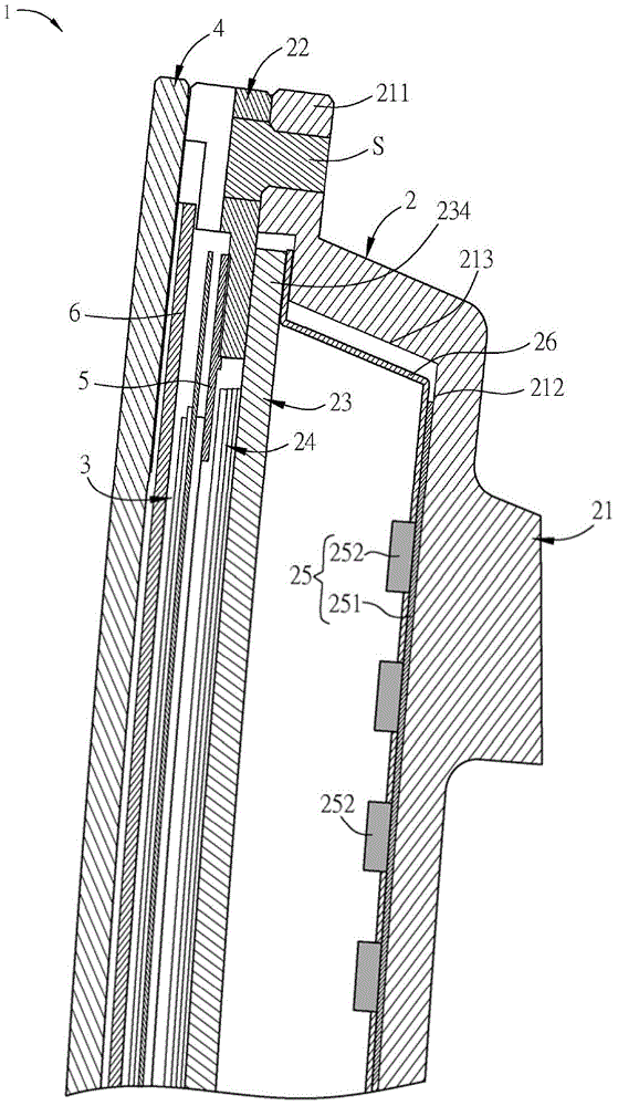
图1C为图1A的显示装置中,沿直线A-A的剖视示意图。FIG. 1C is a schematic cross-sectional view along the line A-A in the display device of FIG. 1A .
图1D是图1C的局部放大示意图。FIG. 1D is a partially enlarged schematic view of FIG. 1C .
图1E为一实施例的发光单元与反射片的俯视示意图。FIG. 1E is a schematic top view of a light-emitting unit and a reflection sheet according to an embodiment.
图2A及图2B分别为不同实施例的光学膜片组的示意图。2A and 2B are schematic diagrams of optical film sets according to different embodiments, respectively.
图3A及图3B分别为本发明另一实施态样的显示装置的立体示意图与分解示意图。FIG. 3A and FIG. 3B are a perspective view and an exploded view of a display device according to another embodiment of the present invention, respectively.
图3C为图3A的显示装置中,沿直线B-B的剖视示意图。FIG. 3C is a schematic cross-sectional view along line B-B of the display device of FIG. 3A .
具体实施方式Detailed ways
以下将参照相关图式,说明依本发明较佳实施例的显示装置,其中相同的元件将以相同的参照符号加以说明。本发明所有实施态样的图示只是示意,不代表真实尺寸与比例。此外,以下实施例的内容中所称的方位“上”及“下”只是用来表示相对的位置关系。再者,一个元件形成在另一个元件“上”、“之上”、“下”或“之下”可包括实施例中的一个元件与另一个元件直接接触,或也可包括一个元件与另一个元件之间还有其他额外元件使一个元件与另一个元件无直接接触。The display device according to the preferred embodiment of the present invention will be described below with reference to the related drawings, wherein the same elements will be described with the same reference symbols. The illustrations of all embodiments of the present invention are only schematic representations, and do not represent actual dimensions and proportions. In addition, the orientations "up" and "down" referred to in the content of the following embodiments are only used to represent relative positional relationships. Furthermore, the fact that an element is formed "on", "over", "under" or "under" another element may include in the embodiments that the one element is in direct contact with the other element, or it may also include the one element being in contact with the other element. There are other additional elements between one element so that one element is not in direct contact with another element.
请参照图1A至图1E所示,其中,图1A及图1B分别为本发明较佳实施例的一种显示装置的立体示意图与分解示意图,图1C为图1A的显示装置中,沿直线A-A的剖视示意图,图1D是图1C的局部放大示意图,而图1E为一实施例的发光单元与反射片的俯视示意图。Please refer to FIGS. 1A to 1E , wherein FIGS. 1A and 1B are a perspective view and an exploded view of a display device according to a preferred embodiment of the present invention, respectively, and FIG. 1C is the display device of FIG. 1A , along a line A-A. FIG. 1D is a partial enlarged schematic view of FIG. 1C , and FIG. 1E is a schematic top view of a light-emitting unit and a reflection sheet according to an embodiment.
本实施例的显示装置1是一曲面显示装置,并为外凸型的曲面显示装置。以下所谓“外凸型”显示装置是表示,相对于观看者而言,显示装置1显示图像的显示面的中间部分较两侧部分突出。相反的,若是“内凹型”显示装置是表示,相对于观看者而言,显示装置显示图像的显示面的两侧部分较中间部分突出。The
显示装置1包括一背光模块2及一显示面板3。背光模块2与显示面板3相对而设,并可发出光线入射至显示面板3,使显示面板3显示图像。本实施例的背光模块2是以直下式背光(direct lighting)的背光模块,并为外凸型背光模块为例。由于显示装置1是一曲面显示装置,故上述的显示面板3与背光模块2的弯曲程度都是相互匹配的,也就是这些元件的弯曲程度(切线斜角的变化率)实质上都是相同的。在一些实施例中,因工艺因素,这些元件的弯曲程度也可稍微不同。The
背光模块2包括一第一弧形固定件21、一第二弧形固定件22、一光学元件23及一光学膜片组24。另外,本实施例的背光模块2更包含一发光单元25及一反射片26。The
第二弧形固定件22与第一弧形固定件21对应设置。于此,第一弧形固定件21与第二弧形固定件22具有相同的切线斜角变化率。其中,第一弧形固定件21可视为一承载件,并具有一内侧底面212及连接于内侧底面212的一外侧周缘211,而第二弧形固定件22是一框件(中间部分镂空),且如图1D所示,第二弧形固定件22连接于第一弧形固定件21的外侧周缘211。其中,第二弧形固定件22可通过例如但不限于锁合(例如利用螺丝),或卡勾方式(例如利用扣件),或铆接方式(例如利用铆钉)连接于第一弧形固定件21的外侧周缘211。本实施例是通过多个结合件S(螺丝)将第二弧形固定件22连接于第一弧形固定件21的外侧周缘211为例。The second arc-shaped fixing
第一弧形固定件21与第二弧形固定件22的材料例如但不限于为塑胶或金属,并可以例如但不限于以CNC加工、压铸(Die Casting)、冲压或是塑件成型等方式来制作,使得第一弧形固定件21与第二弧形固定件22具有相同的切线斜角变化率。较佳者,第一弧形固定件21与第二弧形固定件22为一体成型。因此,相较于已知的背板结构而言,第一弧形固定件21与第二弧形固定件22的切线斜角变化率及尺寸精度的控制可相当精准。藉此,当应用于例如中小型尺寸的曲面显示装置(例如车用产品)时,可具有较高的精度。The material of the first arc-shaped fixing
光学元件23夹置于第一弧形固定件21与第二弧形固定件22之间而形成一曲面。由于本实施例的背光模块2是直下式背光(direct lighting)背光模块,故光学元件23为一扩散板,并为透光材料所制成,透光材料例如但不限于为丙烯酸树脂、聚碳酸酯或聚乙烯树脂,并不限制。其中,未夹置时的光学元件23可为一平板状,或者可与第一弧形固定件21或第二弧形固定件22具有相同切线斜角变化率的曲面状。本实施例的光学元件23为平板状,并具有可挠性。因此,当光学元件23的外侧周缘234夹置于第一弧形固定件21与第二弧形固定件22之间时,除了可使光学元件23成为曲面状之外,更可防止光学元件23因本身的结构应力而回弹。因此,光学元件23可直接使用平板状的扩散板,不需事前制作或弯曲成曲面状,节省制作成本与时间。The
光学膜片组24与光学元件23相邻设置。本实施例的光学膜片组24的面积小于第二弧形固定件22中间的镂空部分,且摆放于光学元件23上而位于显示面板3与光学元件23之间。于此,是以具有四个光学膜片为例,该些光学膜片例如但不限于为集光片、增亮片或扩散片,并通过一遮光件5将光学膜片组24限制在光学元件23的上表面。由于光学元件23已为曲面状,因此,该些光学膜片亦分别为曲面状而具有与光学元件23相同的切线斜角变化率。在一些实施例中,第二弧形固定件22亦可具有部分的向内凸出部以将光学膜片组24固定在光学元件23的上表面,而不需通过遮光件5固定。此外,在其他实施例中,光学膜片组24的面积也可大于第二弧形固定件22中间的镂空部分,且光学膜片组24可和光学元件23一起夹置于第一弧形固定件21和第二弧形固定件22之间,不需通过遮光件5固定。The
另外,在一些实施例中,若显示装置1为外凸型的显示装置时,则其中的一光学膜片水平放置时的长度可小于或等于其中另一光学膜片水平放置时的长度;在一些实施例中,若显示装置1为内凹型的显示装置时,则其中的一光学膜片水平放置时的长度可大于或等于其中另一光学膜片水平放置时的长度。于此,所谓“水平放置时的长度”是表示,在不受其他外力的影响下将光学膜片放置于一平面上时,光学膜片呈现平板状而不弯曲时所呈现的长度。另外,所谓“长度”是表示,光学膜片在弯曲状时,弯曲的边平放时的长度。由于光学膜片可在短边弯曲,也可在长边弯曲,因此上述所称的“长度”并非一定表示光学膜片长边的长度。In addition, in some embodiments, if the
请先参照图2A及图2B所示,其分别为不同实施例的光学膜片组的示意图。Please refer to FIG. 2A and FIG. 2B , which are schematic diagrams of optical film sets according to different embodiments, respectively.
如图2A所示,光学膜片组24是以四片光学膜片(第一光学膜片241~第四光学膜片244)彼此堆叠,并分别为外凸型为例。其中,第一光学膜片241~第四光学膜片244的曲率中心相同,但曲率半径不同。换言之,于图2A的光学膜片组24中,观看者位于光学膜片组24的上侧,且光学元件23位于光学膜片组24的下侧。因此,第一光学膜片241设置于光学元件23与第二光学膜片242之间,第二光学膜片242设置于第一光学膜片241与第三光学膜片243之间,且第三光学膜片243设置于第二光学膜片242与第四光学膜片244之间。As shown in FIG. 2A , the optical film set 24 is an example in which four optical films (the first
由于第一光学膜片241~第四光学膜片244摆放于光学元件23上而分别为外凸型,为了使光学膜片组24的两个侧边不发生漏光现象,因此,第一光学膜片241平放时的长度需小于第二光学膜片242平放时的长度,第二光学膜片242平放时的长度亦需小于第三光学膜片243平放时的长度,且第三光学膜片243平放时的长度亦需小于第四光学膜片244平放时的长度。换言之,离观看者越近的光学膜片水平放置而不弯曲(平板状)时,其弯曲边的长度越长(亦即第四光学膜片244最长)。Since the first
以第三光学膜片243与第四光学膜片244为例,若第四光学膜片244平放时的长度为L,则第三光学膜片243平放时的长度需为:L+L×(Ro/Ri-1)。其中,Ri为第四光学膜片244的曲率半径,而Ro为第三光学膜片243的曲率半径。其他光学膜片(242、241)平放时的长度可以上式公式类推。藉此,可使光学膜片组24的两侧边不发生漏光现象。Taking the third
另外,在不同的实施例中,如图2B所示,若为内凹型的显示装置时,则第一光学膜片241~第四光学膜片244摆放于光学元件23而分别为内凹型。因此,于光学膜片组24’中,观看者同样位于光学膜片组24’的上侧,且光学元件23位于光学膜片组24’的下侧。由于第一光学膜片241~第四光学膜片244分别为内凹型,为了使光学膜片组24’的两侧边不发生漏光现象,故第一光学膜片241平放时的长度需大于第二光学膜片242平放时的长度,第二光学膜片242平放时的长度亦需大于第三光学膜片243平放时的长度,且第三光学膜片243平放时的长度亦需大于第四光学膜片244平放时的长度。换言之,离观看者越近的光学膜片水平放置而不弯曲(平板状)时,其弯曲边的长度越短(亦即第四光学膜片244最短)。此外,第一光学膜片241~第四光学膜片244的长度关系可参照上述,不再多作说明。In addition, in different embodiments, as shown in FIG. 2B , if the display device is a concave type, the first
请再参照图1B及图1D所示,显示面板3与第二弧形固定件22对应设置,并设置于第二弧形固定件22远离光学元件23的一侧。本实施例的显示面板3为液晶显示面板。液晶显示面板具有相对而设的两基板,且一液晶层夹置于两基板之间。于此,显示面板3亦为外凸型显示面板,表示两基板、液晶层及上、下偏光板的切线斜角变化率与第一弧形固定件21、第二弧形固定件22实质上相同。在一些实施例中,显示面板3的切线斜角变化率与第一弧形固定件21、第二弧形固定件22的切线斜角变化率可稍微不同。Referring to FIG. 1B and FIG. 1D again, the
另外,请参照图1D及图1E所示,发光单元25设置于光学元件23与第一弧形固定件21之间。其中,发光单元25具有一基板251及多个发光元件252,该些发光元件252以二维阵排列方式设置于基板251上,而基板251设置于第一弧形固定件21的内侧底面212上。其中,发光单元25可例如通过双面胶粘合于第一弧形固定件21的内侧底面212上而与第一弧形固定件21具有相同的切线斜角变化率。在本实施例中,基板251为一软性印刷电路板(Flexible Print Circuit,FPC,又称软板),而发光元件252为发光二极管。另外,由于本实施例的该些发光元件252是以二维阵排列方式设置于基板251上,故在一些实施例中,背光模块2可具有局部调光(local dimming)的功能。此外,在不同的实施例中,也可利用第一弧形固定件21与第二弧形固定件22以直接压合的方式来使发光单元25形成曲面状,并不限定。In addition, please refer to FIG. 1D and FIG. 1E , the light-emitting
另外,本实例的反射片26具有多个开孔261(参照图1B),且该些开孔261与该些发光元件252是呈现一对一的对应设置。于此,该些发光元件252分别穿过该些开孔261而使反射片26贴合于基板251上。另外,本实施例的反射片26亦设置于第一弧形固定件21四周的一内侧侧面213(参照图1D),并夹置于光学元件23与第一弧形固定件21之间,藉此提高光线利用率。其中,反射片26具有高反射率的材料,高反射率的材料可例如但不限于为金属(例如银)、合金,或二氧化钛(TiO2)与树脂的混合物。利用反射片26可形成一反射率高的反射面,藉此,可使背光模块2具有较高的光线利用率。In addition, the
此外,再补充而说明的是,如图1E所示,本实施例的反射片26为单片式的立体反射片,其与多片式组合而成的反射片主要的不同在于,在反射片26两侧弯曲的部分是具有曲率的弧线,且上、下的骑缝线具有不等长的特征,使其在弯曲时可以自然弯曲,不会有一般平行线无法弯曲的特性。在一些实施例中,反射片亦可为多片式组装(例如三片式),本发明并不限定。In addition, it should be supplemented that, as shown in FIG. 1E , the
另外,本实施例的显示装置1更可包括一触控面板4,触控面板4设置于显示面板3远离背光模块2的一侧,且与显示面板3相对而设。因此,显示装置1亦可称为曲面触控显示装置。在不同的实施例中,显示装置1亦可不设置触控面板4。In addition, the
在实施上,可利用与第一弧形固定件21或第二弧形固定件22具有相同切线斜角变化率的构件(例如弧形玻璃)将显示面板3与触控面板4进行塑形,以使显示面板3与触控面板4成为具有相同切线斜角变化率的构件之后,再与背光模块2组合而形成显示装置1。在一些实施例中,因工艺精度因素,显示面板3与触控面板4的切线斜角变化率与背光模块2的切线斜角变化率可稍微不同。此外,本实施例是通过至少一粘着件6(可为一片或多片)将触控面板4、显示面板3及背光模块2连接组合起来。在一些实施例中,触控面板4、显示面板3及背光模块2也可用其他方式组装。In practice, the
承上,在本实施例的背光模块2中,通过第二弧形固定件22连接于第一弧形固定件21的外缘,并使光学元件23夹置于第一弧形固定件21与第二弧形固定件23之间而形成一曲面,另外,再通过光学膜片组24与光学元件23相邻设置,且显示面板3与第二弧形固定件22对应设置,并设置于第二弧形固定件22远离光学元件23的一侧,藉此,相较于已知显示装置的背板结构具有许多构件且组装繁琐而言,本实施例的背光模块2与显示装置1具有支撑构件较少、组装较容易的优点。On the other hand, in the
另外,请参照图3A至图3C所示,其中,图3A及图3B分别为本发明另一实施态样的显示装置1a的立体示意图与分解示意图,而图3C为图3A的显示装置1a中,沿直线B-B的剖视示意图。In addition, please refer to FIGS. 3A to 3C , wherein FIGS. 3A and 3B are a perspective view and an exploded view of a display device 1 a according to another embodiment of the present invention, respectively, and FIG. 3C is a view of the display device 1 a of FIG. 3A . , a schematic cross-sectional view along line B-B.
与显示装置1主要的不同在于,本实施态样的显示装置1a为内凹型显示装置,而背光模块2a为侧光式背光(edge lighting)的背光模块,故光学元件23a为一导光板,材料例如但不限于为聚碳酸酯(Polycarbonate,PC)或聚甲基丙烯酸甲酯(poly-methylmethacrylate,PMMA)。其中,导光板的作用在于引导光线的传输方向,并通过光线于导光板内部的传递,可使光线由导光板的出光面射出,以形成均匀的面光源。The main difference from the
如图3C所示,光学元件23a具有至少一入光面231、一出光面232及与出光面232相对的一底面233。入光面231与出光面232为相邻的表面,而出光面232为面向光学膜片组24a的表面。另外,本实施例的发光单元25a为一发光二极管光条(light bar),并具有多个发光元件252a设置于基板251a上,且邻设于光学元件23a的入光面231,以发出光线由入光面231入射至光学元件23a,并由出光面232射出。于此,基板251a为弧形,并是一个配合光学元件23a的入光面231的切线斜角变化率的电路基板。另外,本实施例中是以一个发光单元25a对应于光学元件23a的一个入光面231为例,不过,在其他的实施态样中,也可于光学元件23a的入光面231相对的另一表面(另一入光面)设置另一发光单元25a,本发明并不限制。As shown in FIG. 3C , the
另外,背光模块2a的反射片26a设置于光学元件23a与第一弧形固定件21a之间,以将由光学元件23a的底面233射出的光线再反射至光学元件23a内,藉此提高光线利用率。于此,反射片26a可包含高反射率的反射层,并为单片式的反射片。在其他实施例中,反射片亦可为多片式组合而成的反射片。In addition, the
此外,背光模块2a与显示装置1a的其它技术特征可分别参照背光模块2与显示装置1的相同元件,不再赘述。In addition, other technical features of the
综上所述,在本发明的显示装置中,通过第二弧形固定件连接于第一弧形固定件的外缘,并使光学元件夹置于第一弧形固定件与第二弧形固定件之间而形成一曲面,另外,再通过光学膜片组与光学元件相邻设置,且显示面板与第二弧形固定件对应设置,并设置于第二弧形固定件远离光学元件的一侧,藉此,相较于已知显示装置具有许多构件而且组装繁琐而言,本发明的显示装置具有支撑构件较少、组装较容易的优点。To sum up, in the display device of the present invention, the second arc-shaped fixing member is connected to the outer edge of the first arc-shaped fixing member, and the optical element is sandwiched between the first arc-shaped fixing member and the second arc-shaped fixing member. A curved surface is formed between the fixing members, and in addition, the optical film group is arranged adjacent to the optical element, and the display panel is arranged corresponding to the second arc-shaped fixing member, and is arranged on the second arc-shaped fixing member away from the optical element. Therefore, compared with the conventional display device which has many components and is complicated to assemble, the display device of the present invention has the advantages of fewer supporting components and easier assembly.
以上所述仅为举例性,而非为限制性者。任何未脱离本发明的精神与范畴,而对其进行的等效修改或变更,均应包含于权利要求中。The above description is exemplary only, not limiting. Any equivalent modifications or changes without departing from the spirit and scope of the present invention should be included in the claims.
Claims (9)
Priority Applications (3)
| Application Number | Priority Date | Filing Date | Title |
|---|---|---|---|
| CN201610279365.1A CN107329301B (en) | 2016-04-29 | 2016-04-29 | display device |
| CN202010959275.3A CN112034652A (en) | 2016-04-29 | 2016-04-29 | Display device |
| US15/483,590 US10788707B2 (en) | 2016-04-29 | 2017-04-10 | Curved display device with arc-shaped fixing members |
Applications Claiming Priority (1)
| Application Number | Priority Date | Filing Date | Title |
|---|---|---|---|
| CN201610279365.1A CN107329301B (en) | 2016-04-29 | 2016-04-29 | display device |
Related Child Applications (1)
| Application Number | Title | Priority Date | Filing Date |
|---|---|---|---|
| CN202010959275.3A Division CN112034652A (en) | 2016-04-29 | 2016-04-29 | Display device |
Publications (2)
| Publication Number | Publication Date |
|---|---|
| CN107329301A CN107329301A (en) | 2017-11-07 |
| CN107329301B true CN107329301B (en) | 2020-10-16 |
Family
ID=60158905
Family Applications (2)
| Application Number | Title | Priority Date | Filing Date |
|---|---|---|---|
| CN201610279365.1A Active CN107329301B (en) | 2016-04-29 | 2016-04-29 | display device |
| CN202010959275.3A Pending CN112034652A (en) | 2016-04-29 | 2016-04-29 | Display device |
Family Applications After (1)
| Application Number | Title | Priority Date | Filing Date |
|---|---|---|---|
| CN202010959275.3A Pending CN112034652A (en) | 2016-04-29 | 2016-04-29 | Display device |
Country Status (2)
| Country | Link |
|---|---|
| US (1) | US10788707B2 (en) |
| CN (2) | CN107329301B (en) |
Cited By (1)
| Publication number | Priority date | Publication date | Assignee | Title |
|---|---|---|---|---|
| US12460795B2 (en) | 2022-12-27 | 2025-11-04 | CarUX Technology Pte. Ltd. | Electronic device and manufacturing method thereof |
Families Citing this family (33)
| Publication number | Priority date | Publication date | Assignee | Title |
|---|---|---|---|---|
| JP6327111B2 (en) * | 2014-10-23 | 2018-05-23 | 株式会社デンソー | Vehicle display unit, display control unit |
| US9997010B2 (en) | 2015-12-18 | 2018-06-12 | Ags Llc | Electronic gaming device with external lighting functionality |
| KR20180121568A (en) | 2016-03-09 | 2018-11-07 | 코닝 인코포레이티드 | Cold Forming of Composite Curved Glass Products |
| KR102513536B1 (en) | 2016-06-28 | 2023-03-24 | 코닝 인코포레이티드 | Laminating thin strengthened glass to curved molded plastic surface for decorative and display cover application |
| EP3482253B1 (en) | 2016-07-05 | 2021-05-05 | Corning Incorporated | Cold-formed glass article and assembly process thereof |
| CN113157125A (en) | 2017-01-03 | 2021-07-23 | 康宁公司 | Vehicle interior system with curved cover glass and display or touch panel and method of forming same |
| US11016590B2 (en) | 2017-01-03 | 2021-05-25 | Corning Incorporated | Vehicle interior systems having a curved cover glass and display or touch panel and methods for forming the same |
| USD843473S1 (en) | 2017-04-07 | 2019-03-19 | Ags Llc | Gaming machine |
| JP2020533217A (en) | 2017-07-18 | 2020-11-19 | コーニング インコーポレイテッド | Cold molding of intricately curved glass articles |
| KR102669222B1 (en) | 2017-09-12 | 2024-05-24 | 코닝 인코포레이티드 | Deadfront for displays including a touch panel on decorative glass and related methods |
| TWI873668B (en) | 2017-09-13 | 2025-02-21 | 美商康寧公司 | Light guide-based deadfront for display, related methods and vehicle interior systems |
| US11065960B2 (en) | 2017-09-13 | 2021-07-20 | Corning Incorporated | Curved vehicle displays |
| TWI844520B (en) | 2017-10-10 | 2024-06-11 | 美商康寧公司 | Vehicle interior systems having a curved cover glass with improved reliability and methods for forming the same |
| KR102707453B1 (en) | 2017-11-21 | 2024-09-23 | 코닝 인코포레이티드 | Aspherical mirror for head-up display system and method for forming same |
| EP3717958A4 (en) | 2017-11-30 | 2021-08-04 | Corning Incorporated | SYSTEMS AND PROCESSES FOR THE VACUUM FORMING OF ASPHERICAL MIRRORS |
| EP3717415B1 (en) | 2017-11-30 | 2023-03-01 | 1/4 Corning Incorporated | Vacuum mold apparatus and methods for forming curved mirrors |
| USD899526S1 (en) | 2018-02-02 | 2020-10-20 | Ags Llc | Support structure for gaming machine display |
| CN111936891B (en) | 2018-03-02 | 2023-03-24 | 康宁公司 | Anti-reflective coating and article and method of forming the same |
| CN108257507B (en) | 2018-03-02 | 2021-01-15 | 上海天马微电子有限公司 | A curved display device and method of making the same |
| US11718071B2 (en) | 2018-03-13 | 2023-08-08 | Corning Incorporated | Vehicle interior systems having a crack resistant curved cover glass and methods for forming the same |
| EP3820826A1 (en) | 2018-07-12 | 2021-05-19 | Corning Incorporated | Deadfront configured for color matching |
| EP3823825A1 (en) | 2018-07-16 | 2021-05-26 | Corning Incorporated | Vehicle interior systems having a cold-bent glass substrate and methods for forming the same |
| USD939632S1 (en) | 2018-07-17 | 2021-12-28 | Ags Llc | Gaming machine |
| JP7240111B2 (en) * | 2018-08-09 | 2023-03-15 | Tianma Japan株式会社 | Display device |
| USD969926S1 (en) | 2019-04-24 | 2022-11-15 | Ags Llc | Gaming machine |
| CN110297357B (en) * | 2019-06-27 | 2021-04-09 | 厦门天马微电子有限公司 | Preparation method of curved surface backlight module, curved surface backlight module and display device |
| EP3771695A1 (en) | 2019-07-31 | 2021-02-03 | Corning Incorporated | Method and system for cold-forming glass |
| USD978810S1 (en) | 2019-07-31 | 2023-02-21 | Ags Llc | LED matrix display |
| US11380157B2 (en) | 2019-08-02 | 2022-07-05 | Ags Llc | Servicing and mounting features for gaming machine display screens and toppers |
| USD969927S1 (en) | 2019-08-02 | 2022-11-15 | Ags Llc | Gaming machine |
| US12466756B2 (en) | 2019-10-08 | 2025-11-11 | Corning Incorporated | Curved glass articles including a bumper piece configured to relocate bending moment from display region and method of manufacturing same |
| US11300819B2 (en) * | 2019-12-20 | 2022-04-12 | Beijing Boe Display Technology Co., Ltd. | Curved surface display device having backlight assembly with frame members |
| US11772361B2 (en) | 2020-04-02 | 2023-10-03 | Corning Incorporated | Curved glass constructions and methods for forming same |
Citations (4)
| Publication number | Priority date | Publication date | Assignee | Title |
|---|---|---|---|---|
| CN202955582U (en) * | 2012-12-14 | 2013-05-29 | 厦门天马微电子有限公司 | Backlight module and liquid crystal display device |
| CN103323969A (en) * | 2013-05-29 | 2013-09-25 | 业成光电(深圳)有限公司 | Display device, touch display device with display device, electronic device with display device |
| CN104977752A (en) * | 2014-04-07 | 2015-10-14 | 三星显示有限公司 | display device |
| CN105090813A (en) * | 2015-03-20 | 2015-11-25 | 深圳市华星光电技术有限公司 | Backlight module and display device |
Family Cites Families (22)
| Publication number | Priority date | Publication date | Assignee | Title |
|---|---|---|---|---|
| US4825212A (en) * | 1986-11-14 | 1989-04-25 | Zenith Electronics Corporation | Arrangement for use with a touch control system having a spherically curved touch surface |
| JP4403099B2 (en) * | 2005-04-19 | 2010-01-20 | シャープ株式会社 | Backlight device and liquid crystal display device |
| KR101335741B1 (en) * | 2007-06-04 | 2013-12-02 | 엘지전자 주식회사 | Display apparatus |
| KR101841901B1 (en) * | 2010-08-25 | 2018-03-26 | 삼성전자주식회사 | Liquid crystal display device |
| TWI418900B (en) * | 2010-12-30 | 2013-12-11 | Au Optronics Corp | Backlight module and display device utilizing the same |
| CN103425302A (en) * | 2012-05-16 | 2013-12-04 | 宸鸿科技(厦门)有限公司 | Touch panel and production method thereof |
| US9323084B2 (en) * | 2012-11-08 | 2016-04-26 | Lg Display Co., Ltd. | Curved liquid crystal display device |
| JP2015114643A (en) * | 2013-12-16 | 2015-06-22 | 株式会社ジャパンディスプレイ | Liquid crystal display device |
| EP2913707B1 (en) * | 2014-02-28 | 2019-08-07 | Samsung Electronics Co., Ltd | Rear Chassis for a Curved Panel Display |
| CN203909434U (en) * | 2014-03-05 | 2014-10-29 | 群创光电股份有限公司 | Display device |
| US9323086B2 (en) * | 2014-03-21 | 2016-04-26 | Shenzhen China Star Optoelectronics Technology Co., Ltd. | Curved liquid crystal display device |
| KR20160022420A (en) * | 2014-08-19 | 2016-03-02 | 삼성디스플레이 주식회사 | Display device |
| KR102241557B1 (en) * | 2014-09-22 | 2021-04-19 | 삼성디스플레이 주식회사 | Display device |
| CN104266116B (en) * | 2014-10-09 | 2017-03-15 | 深圳市华星光电技术有限公司 | A kind of backing structure and LCDs |
| KR20160047037A (en) * | 2014-10-21 | 2016-05-02 | 삼성디스플레이 주식회사 | Display device |
| KR102301373B1 (en) * | 2014-10-27 | 2021-09-14 | 삼성전자주식회사 | Display apparatus |
| JP6539067B2 (en) * | 2015-03-04 | 2019-07-03 | 株式会社ジャパンディスプレイ | Display device and electronic component |
| KR102367068B1 (en) * | 2015-03-31 | 2022-02-24 | 삼성전자주식회사 | Display apparatus |
| KR102339539B1 (en) * | 2015-05-08 | 2021-12-16 | 삼성전자주식회사 | Display apparatus |
| JP6441477B2 (en) * | 2015-06-15 | 2018-12-19 | 堺ディスプレイプロダクト株式会社 | Display device |
| CN105093615B (en) * | 2015-07-29 | 2018-01-26 | 合肥鑫晟光电科技有限公司 | Curved face display panel and preparation method thereof, display device |
| KR102469764B1 (en) * | 2016-01-15 | 2022-11-23 | 삼성디스플레이 주식회사 | Backlight unit, display device and method of manufacturing the display device |
-
2016
- 2016-04-29 CN CN201610279365.1A patent/CN107329301B/en active Active
- 2016-04-29 CN CN202010959275.3A patent/CN112034652A/en active Pending
-
2017
- 2017-04-10 US US15/483,590 patent/US10788707B2/en active Active
Patent Citations (4)
| Publication number | Priority date | Publication date | Assignee | Title |
|---|---|---|---|---|
| CN202955582U (en) * | 2012-12-14 | 2013-05-29 | 厦门天马微电子有限公司 | Backlight module and liquid crystal display device |
| CN103323969A (en) * | 2013-05-29 | 2013-09-25 | 业成光电(深圳)有限公司 | Display device, touch display device with display device, electronic device with display device |
| CN104977752A (en) * | 2014-04-07 | 2015-10-14 | 三星显示有限公司 | display device |
| CN105090813A (en) * | 2015-03-20 | 2015-11-25 | 深圳市华星光电技术有限公司 | Backlight module and display device |
Cited By (1)
| Publication number | Priority date | Publication date | Assignee | Title |
|---|---|---|---|---|
| US12460795B2 (en) | 2022-12-27 | 2025-11-04 | CarUX Technology Pte. Ltd. | Electronic device and manufacturing method thereof |
Also Published As
| Publication number | Publication date |
|---|---|
| CN107329301A (en) | 2017-11-07 |
| US10788707B2 (en) | 2020-09-29 |
| US20170315407A1 (en) | 2017-11-02 |
| CN112034652A (en) | 2020-12-04 |
Similar Documents
| Publication | Publication Date | Title |
|---|---|---|
| CN107329301B (en) | display device | |
| CN101819290B (en) | Optical sheet, backlight device and liquid crystal display device | |
| CN101630089B (en) | Backlight module and liquid crystal display using same | |
| JP6267936B2 (en) | Curved display device | |
| JP6207852B2 (en) | Display device | |
| US9022630B2 (en) | Display module and apparatus having the same | |
| US20140126238A1 (en) | Light source module and manufacturing method thereof | |
| US9823509B2 (en) | Display device | |
| US9261721B2 (en) | Display apparatus | |
| US20190204684A1 (en) | Backlight unit and display device having the same | |
| CN105867027A (en) | Backlight module, liquid crystal display module and liquid crystal display device | |
| CN206353230U (en) | Backboard, backlight and display device | |
| KR20210025308A (en) | Display device having glass diffuser plast | |
| CN118605053A (en) | Electronic Devices | |
| JP5312919B2 (en) | Liquid crystal display | |
| CN107688253A (en) | Display device | |
| US9551894B2 (en) | Display | |
| CN110908191A (en) | Display module and display device | |
| JP2008198481A (en) | Curved surface light source device, curved liquid crystal display device, and manufacturing method thereof | |
| JP2019021474A (en) | Backlight device and liquid crystal display device including the same | |
| US20080088767A1 (en) | Backlight module and liquid crystal display with same | |
| EP2821819A1 (en) | Reflectors for the corners of a direct backlight in a display device | |
| CN101008739A (en) | Optical film, backlight module, display device, optoelectronic device and manufacturing method thereof | |
| JP2001117069A (en) | Display device and display panel used for display device | |
| CN101936485A (en) | Optical film, backlight module, display device, photoelectric device and manufacturing method thereof |
Legal Events
| Date | Code | Title | Description |
|---|---|---|---|
| PB01 | Publication | ||
| PB01 | Publication | ||
| SE01 | Entry into force of request for substantive examination | ||
| SE01 | Entry into force of request for substantive examination | ||
| GR01 | Patent grant | ||
| GR01 | Patent grant |