CN107187022B - Three-dimensional printing - Google Patents
Three-dimensional printing Download PDFInfo
- Publication number
- CN107187022B CN107187022B CN201710447361.4A CN201710447361A CN107187022B CN 107187022 B CN107187022 B CN 107187022B CN 201710447361 A CN201710447361 A CN 201710447361A CN 107187022 B CN107187022 B CN 107187022B
- Authority
- CN
- China
- Prior art keywords
- nozzle
- core
- core reinforcing
- filament
- filaments
- Prior art date
- Legal status (The legal status is an assumption and is not a legal conclusion. Google has not performed a legal analysis and makes no representation as to the accuracy of the status listed.)
- Expired - Fee Related
Links
- 238000010146 3D printing Methods 0.000 title description 62
- 238000000034 method Methods 0.000 claims abstract description 168
- 230000003014 reinforcing effect Effects 0.000 claims abstract description 156
- 239000011159 matrix material Substances 0.000 claims abstract description 110
- 238000001125 extrusion Methods 0.000 claims abstract description 60
- 238000002844 melting Methods 0.000 claims abstract description 32
- 230000008018 melting Effects 0.000 claims abstract description 32
- 230000007246 mechanism Effects 0.000 claims description 112
- 238000007639 printing Methods 0.000 claims description 69
- 238000010438 heat treatment Methods 0.000 claims description 64
- 238000005520 cutting process Methods 0.000 claims description 45
- 239000007787 solid Substances 0.000 claims description 41
- 238000004519 manufacturing process Methods 0.000 claims description 33
- 239000012530 fluid Substances 0.000 claims description 30
- 238000011144 upstream manufacturing Methods 0.000 claims description 19
- 238000005056 compaction Methods 0.000 claims description 15
- 238000005452 bending Methods 0.000 claims description 12
- 238000004891 communication Methods 0.000 claims description 10
- 239000011162 core material Substances 0.000 description 515
- 239000000463 material Substances 0.000 description 386
- 239000000835 fiber Substances 0.000 description 126
- 230000008569 process Effects 0.000 description 98
- 229920005989 resin Polymers 0.000 description 90
- 239000011347 resin Substances 0.000 description 90
- 239000010410 layer Substances 0.000 description 89
- 229920000642 polymer Polymers 0.000 description 83
- 239000002131 composite material Substances 0.000 description 65
- 239000003570 air Substances 0.000 description 39
- 238000000151 deposition Methods 0.000 description 32
- 238000000576 coating method Methods 0.000 description 30
- 239000011248 coating agent Substances 0.000 description 27
- 238000005470 impregnation Methods 0.000 description 26
- 230000002787 reinforcement Effects 0.000 description 25
- 239000012783 reinforcing fiber Substances 0.000 description 23
- 238000009736 wetting Methods 0.000 description 22
- 238000001816 cooling Methods 0.000 description 21
- 230000008021 deposition Effects 0.000 description 21
- 230000015572 biosynthetic process Effects 0.000 description 19
- 230000001965 increasing effect Effects 0.000 description 19
- 230000007704 transition Effects 0.000 description 19
- 229910000679 solder Inorganic materials 0.000 description 18
- 230000008901 benefit Effects 0.000 description 17
- 239000007788 liquid Substances 0.000 description 16
- 239000000155 melt Substances 0.000 description 16
- 230000006835 compression Effects 0.000 description 14
- 238000007906 compression Methods 0.000 description 14
- 239000011148 porous material Substances 0.000 description 14
- 238000004140 cleaning Methods 0.000 description 13
- 229920003023 plastic Polymers 0.000 description 13
- 239000004033 plastic Substances 0.000 description 13
- RYGMFSIKBFXOCR-UHFFFAOYSA-N Copper Chemical compound [Cu] RYGMFSIKBFXOCR-UHFFFAOYSA-N 0.000 description 12
- 238000013461 design Methods 0.000 description 11
- 229910052751 metal Inorganic materials 0.000 description 11
- 239000002184 metal Substances 0.000 description 11
- 230000002829 reductive effect Effects 0.000 description 10
- 238000001723 curing Methods 0.000 description 9
- 238000011049 filling Methods 0.000 description 9
- -1 plasmas Substances 0.000 description 9
- 229920000049 Carbon (fiber) Polymers 0.000 description 8
- 239000004677 Nylon Substances 0.000 description 8
- 239000000654 additive Substances 0.000 description 8
- 230000000996 additive effect Effects 0.000 description 8
- 239000004917 carbon fiber Substances 0.000 description 8
- 238000005137 deposition process Methods 0.000 description 8
- 239000000945 filler Substances 0.000 description 8
- 229920001778 nylon Polymers 0.000 description 8
- 230000003287 optical effect Effects 0.000 description 8
- 239000004020 conductor Substances 0.000 description 7
- 229910052802 copper Inorganic materials 0.000 description 7
- 239000010949 copper Substances 0.000 description 7
- 238000010586 diagram Methods 0.000 description 7
- 230000006870 function Effects 0.000 description 7
- 229920005992 thermoplastic resin Polymers 0.000 description 7
- CBENFWSGALASAD-UHFFFAOYSA-N Ozone Chemical compound [O-][O+]=O CBENFWSGALASAD-UHFFFAOYSA-N 0.000 description 6
- 239000011230 binding agent Substances 0.000 description 6
- 230000009477 glass transition Effects 0.000 description 6
- VNWKTOKETHGBQD-UHFFFAOYSA-N methane Chemical compound C VNWKTOKETHGBQD-UHFFFAOYSA-N 0.000 description 6
- 239000002245 particle Substances 0.000 description 6
- 238000002203 pretreatment Methods 0.000 description 6
- 238000010008 shearing Methods 0.000 description 6
- 239000007858 starting material Substances 0.000 description 6
- 238000010276 construction Methods 0.000 description 5
- 239000007789 gas Substances 0.000 description 5
- 230000001976 improved effect Effects 0.000 description 5
- 230000006698 induction Effects 0.000 description 5
- 238000002156 mixing Methods 0.000 description 5
- 229920001343 polytetrafluoroethylene Polymers 0.000 description 5
- 239000004810 polytetrafluoroethylene Substances 0.000 description 5
- 238000012545 processing Methods 0.000 description 5
- 239000004593 Epoxy Substances 0.000 description 4
- 229920006060 Grivory® Polymers 0.000 description 4
- XEEYBQQBJWHFJM-UHFFFAOYSA-N Iron Chemical compound [Fe] XEEYBQQBJWHFJM-UHFFFAOYSA-N 0.000 description 4
- 239000004952 Polyamide Substances 0.000 description 4
- 229910000831 Steel Inorganic materials 0.000 description 4
- 239000000853 adhesive Substances 0.000 description 4
- 230000001070 adhesive effect Effects 0.000 description 4
- 239000012080 ambient air Substances 0.000 description 4
- 238000009826 distribution Methods 0.000 description 4
- 230000001747 exhibiting effect Effects 0.000 description 4
- 239000002657 fibrous material Substances 0.000 description 4
- 230000000670 limiting effect Effects 0.000 description 4
- 239000000203 mixture Substances 0.000 description 4
- 230000007935 neutral effect Effects 0.000 description 4
- 239000013307 optical fiber Substances 0.000 description 4
- 229920002647 polyamide Polymers 0.000 description 4
- 238000000110 selective laser sintering Methods 0.000 description 4
- 238000009958 sewing Methods 0.000 description 4
- 239000002904 solvent Substances 0.000 description 4
- 239000010959 steel Substances 0.000 description 4
- 239000000758 substrate Substances 0.000 description 4
- 229920001169 thermoplastic Polymers 0.000 description 4
- 239000004416 thermosoftening plastic Substances 0.000 description 4
- 238000013519 translation Methods 0.000 description 4
- OKTJSMMVPCPJKN-UHFFFAOYSA-N Carbon Chemical compound [C] OKTJSMMVPCPJKN-UHFFFAOYSA-N 0.000 description 3
- 230000009471 action Effects 0.000 description 3
- 230000004913 activation Effects 0.000 description 3
- 239000011324 bead Substances 0.000 description 3
- 239000000919 ceramic Substances 0.000 description 3
- 239000000109 continuous material Substances 0.000 description 3
- 238000001514 detection method Methods 0.000 description 3
- 238000006073 displacement reaction Methods 0.000 description 3
- 239000011152 fibreglass Substances 0.000 description 3
- 239000012943 hotmelt Substances 0.000 description 3
- 239000011810 insulating material Substances 0.000 description 3
- 239000000314 lubricant Substances 0.000 description 3
- 239000012762 magnetic filler Substances 0.000 description 3
- 238000012986 modification Methods 0.000 description 3
- 230000004048 modification Effects 0.000 description 3
- 239000003607 modifier Substances 0.000 description 3
- MWUXSHHQAYIFBG-UHFFFAOYSA-N nitrogen oxide Inorganic materials O=[N] MWUXSHHQAYIFBG-UHFFFAOYSA-N 0.000 description 3
- 239000002952 polymeric resin Substances 0.000 description 3
- 239000000843 powder Substances 0.000 description 3
- 239000002994 raw material Substances 0.000 description 3
- 229920006012 semi-aromatic polyamide Polymers 0.000 description 3
- 238000007711 solidification Methods 0.000 description 3
- 230000008023 solidification Effects 0.000 description 3
- 239000000243 solution Substances 0.000 description 3
- 229910001220 stainless steel Inorganic materials 0.000 description 3
- 239000010935 stainless steel Substances 0.000 description 3
- 239000000126 substance Substances 0.000 description 3
- 230000008093 supporting effect Effects 0.000 description 3
- 229920003002 synthetic resin Polymers 0.000 description 3
- IKHGUXGNUITLKF-UHFFFAOYSA-N Acetaldehyde Chemical group CC=O IKHGUXGNUITLKF-UHFFFAOYSA-N 0.000 description 2
- 229910001369 Brass Inorganic materials 0.000 description 2
- MHAJPDPJQMAIIY-UHFFFAOYSA-N Hydrogen peroxide Chemical group OO MHAJPDPJQMAIIY-UHFFFAOYSA-N 0.000 description 2
- 229920000271 Kevlar® Polymers 0.000 description 2
- 229920000106 Liquid crystal polymer Polymers 0.000 description 2
- 239000004977 Liquid-crystal polymers (LCPs) Substances 0.000 description 2
- 239000004696 Poly ether ether ketone Substances 0.000 description 2
- 239000004697 Polyetherimide Substances 0.000 description 2
- 230000001133 acceleration Effects 0.000 description 2
- 239000004676 acrylonitrile butadiene styrene Substances 0.000 description 2
- 239000004840 adhesive resin Substances 0.000 description 2
- 229920006223 adhesive resin Polymers 0.000 description 2
- 238000013459 approach Methods 0.000 description 2
- 230000009286 beneficial effect Effects 0.000 description 2
- 230000000903 blocking effect Effects 0.000 description 2
- 239000010951 brass Substances 0.000 description 2
- 239000002041 carbon nanotube Substances 0.000 description 2
- 229910021393 carbon nanotube Inorganic materials 0.000 description 2
- 239000012459 cleaning agent Substances 0.000 description 2
- 239000011538 cleaning material Substances 0.000 description 2
- 239000003086 colorant Substances 0.000 description 2
- 150000001875 compounds Chemical class 0.000 description 2
- 238000004132 cross linking Methods 0.000 description 2
- 238000000354 decomposition reaction Methods 0.000 description 2
- 230000007423 decrease Effects 0.000 description 2
- 238000007598 dipping method Methods 0.000 description 2
- 238000005553 drilling Methods 0.000 description 2
- 230000005670 electromagnetic radiation Effects 0.000 description 2
- 238000009730 filament winding Methods 0.000 description 2
- 239000003365 glass fiber Substances 0.000 description 2
- 230000036541 health Effects 0.000 description 2
- 238000007654 immersion Methods 0.000 description 2
- 238000002347 injection Methods 0.000 description 2
- 239000007924 injection Substances 0.000 description 2
- 238000007689 inspection Methods 0.000 description 2
- 229910052742 iron Inorganic materials 0.000 description 2
- 230000009191 jumping Effects 0.000 description 2
- 239000004761 kevlar Substances 0.000 description 2
- 238000003754 machining Methods 0.000 description 2
- 239000000696 magnetic material Substances 0.000 description 2
- 238000009996 mechanical pre-treatment Methods 0.000 description 2
- 150000002739 metals Chemical class 0.000 description 2
- 238000013508 migration Methods 0.000 description 2
- 230000005012 migration Effects 0.000 description 2
- 239000012768 molten material Substances 0.000 description 2
- 238000012544 monitoring process Methods 0.000 description 2
- 210000002381 plasma Anatomy 0.000 description 2
- 239000004014 plasticizer Substances 0.000 description 2
- 229920000647 polyepoxide Polymers 0.000 description 2
- 229920002530 polyetherether ketone Polymers 0.000 description 2
- 229920001601 polyetherimide Polymers 0.000 description 2
- 239000002861 polymer material Substances 0.000 description 2
- 238000012805 post-processing Methods 0.000 description 2
- 238000011417 postcuring Methods 0.000 description 2
- 230000001737 promoting effect Effects 0.000 description 2
- 239000011253 protective coating Substances 0.000 description 2
- 230000009467 reduction Effects 0.000 description 2
- 238000007665 sagging Methods 0.000 description 2
- 239000002344 surface layer Substances 0.000 description 2
- 239000004034 viscosity adjusting agent Substances 0.000 description 2
- 238000004804 winding Methods 0.000 description 2
- WYTZZXDRDKSJID-UHFFFAOYSA-N (3-aminopropyl)triethoxysilane Chemical compound CCO[Si](OCC)(OCC)CCCN WYTZZXDRDKSJID-UHFFFAOYSA-N 0.000 description 1
- 206010013642 Drooling Diseases 0.000 description 1
- 239000006057 Non-nutritive feed additive Substances 0.000 description 1
- 208000008630 Sialorrhea Diseases 0.000 description 1
- BQCADISMDOOEFD-UHFFFAOYSA-N Silver Chemical compound [Ag] BQCADISMDOOEFD-UHFFFAOYSA-N 0.000 description 1
- ATJFFYVFTNAWJD-UHFFFAOYSA-N Tin Chemical compound [Sn] ATJFFYVFTNAWJD-UHFFFAOYSA-N 0.000 description 1
- RTAQQCXQSZGOHL-UHFFFAOYSA-N Titanium Chemical compound [Ti] RTAQQCXQSZGOHL-UHFFFAOYSA-N 0.000 description 1
- 239000007983 Tris buffer Substances 0.000 description 1
- 239000012963 UV stabilizer Substances 0.000 description 1
- 238000005299 abrasion Methods 0.000 description 1
- 238000009825 accumulation Methods 0.000 description 1
- 230000003213 activating effect Effects 0.000 description 1
- 239000002318 adhesion promoter Substances 0.000 description 1
- 229910052782 aluminium Inorganic materials 0.000 description 1
- XAGFODPZIPBFFR-UHFFFAOYSA-N aluminium Chemical compound [Al] XAGFODPZIPBFFR-UHFFFAOYSA-N 0.000 description 1
- 238000004873 anchoring Methods 0.000 description 1
- 229920006231 aramid fiber Polymers 0.000 description 1
- QVGXLLKOCUKJST-UHFFFAOYSA-N atomic oxygen Chemical compound [O] QVGXLLKOCUKJST-UHFFFAOYSA-N 0.000 description 1
- 238000007664 blowing Methods 0.000 description 1
- 239000007767 bonding agent Substances 0.000 description 1
- 239000003990 capacitor Substances 0.000 description 1
- 229910052799 carbon Inorganic materials 0.000 description 1
- 238000003763 carbonization Methods 0.000 description 1
- 125000002843 carboxylic acid group Chemical group 0.000 description 1
- 230000015556 catabolic process Effects 0.000 description 1
- 230000008859 change Effects 0.000 description 1
- 239000013043 chemical agent Substances 0.000 description 1
- 239000003795 chemical substances by application Substances 0.000 description 1
- 238000005229 chemical vapour deposition Methods 0.000 description 1
- 229920001688 coating polymer Polymers 0.000 description 1
- 238000007596 consolidation process Methods 0.000 description 1
- 239000000356 contaminant Substances 0.000 description 1
- 239000002537 cosmetic Substances 0.000 description 1
- 230000003247 decreasing effect Effects 0.000 description 1
- 238000006731 degradation reaction Methods 0.000 description 1
- 230000002939 deleterious effect Effects 0.000 description 1
- 230000000881 depressing effect Effects 0.000 description 1
- 238000011161 development Methods 0.000 description 1
- 238000009792 diffusion process Methods 0.000 description 1
- 238000003618 dip coating Methods 0.000 description 1
- 239000006185 dispersion Substances 0.000 description 1
- 230000000694 effects Effects 0.000 description 1
- 230000008030 elimination Effects 0.000 description 1
- 238000003379 elimination reaction Methods 0.000 description 1
- 239000000839 emulsion Substances 0.000 description 1
- 239000003623 enhancer Substances 0.000 description 1
- 230000007613 environmental effect Effects 0.000 description 1
- 125000003700 epoxy group Chemical group 0.000 description 1
- 239000003822 epoxy resin Substances 0.000 description 1
- 125000001301 ethoxy group Chemical group [H]C([H])([H])C([H])([H])O* 0.000 description 1
- 238000000605 extraction Methods 0.000 description 1
- 239000003000 extruded plastic Substances 0.000 description 1
- 239000004744 fabric Substances 0.000 description 1
- 239000013305 flexible fiber Substances 0.000 description 1
- 239000006260 foam Substances 0.000 description 1
- 239000002783 friction material Substances 0.000 description 1
- PCHJSUWPFVWCPO-UHFFFAOYSA-N gold Chemical compound [Au] PCHJSUWPFVWCPO-UHFFFAOYSA-N 0.000 description 1
- 229910052737 gold Inorganic materials 0.000 description 1
- 239000010931 gold Substances 0.000 description 1
- 150000004820 halides Chemical class 0.000 description 1
- 239000012760 heat stabilizer Substances 0.000 description 1
- FFUAGWLWBBFQJT-UHFFFAOYSA-N hexamethyldisilazane Chemical compound C[Si](C)(C)N[Si](C)(C)C FFUAGWLWBBFQJT-UHFFFAOYSA-N 0.000 description 1
- 125000002887 hydroxy group Chemical group [H]O* 0.000 description 1
- 239000013072 incoming material Substances 0.000 description 1
- 230000001939 inductive effect Effects 0.000 description 1
- 238000001802 infusion Methods 0.000 description 1
- 238000001746 injection moulding Methods 0.000 description 1
- 239000011256 inorganic filler Substances 0.000 description 1
- 229910003475 inorganic filler Inorganic materials 0.000 description 1
- 230000010354 integration Effects 0.000 description 1
- 230000003993 interaction Effects 0.000 description 1
- 239000011229 interlayer Substances 0.000 description 1
- 230000001678 irradiating effect Effects 0.000 description 1
- 239000007791 liquid phase Substances 0.000 description 1
- 238000011068 loading method Methods 0.000 description 1
- 230000007774 longterm Effects 0.000 description 1
- 239000010687 lubricating oil Substances 0.000 description 1
- 238000005259 measurement Methods 0.000 description 1
- 238000000465 moulding Methods 0.000 description 1
- 239000003921 oil Substances 0.000 description 1
- 229920000620 organic polymer Polymers 0.000 description 1
- 239000001301 oxygen Substances 0.000 description 1
- 229910052760 oxygen Inorganic materials 0.000 description 1
- WURFKUQACINBSI-UHFFFAOYSA-M ozonide Chemical group [O]O[O-] WURFKUQACINBSI-UHFFFAOYSA-M 0.000 description 1
- 230000036961 partial effect Effects 0.000 description 1
- 230000035515 penetration Effects 0.000 description 1
- 150000002978 peroxides Chemical group 0.000 description 1
- 239000012071 phase Substances 0.000 description 1
- 239000000049 pigment Substances 0.000 description 1
- 150000003071 polychlorinated biphenyls Chemical class 0.000 description 1
- 239000004626 polylactic acid Substances 0.000 description 1
- 238000010094 polymer processing Methods 0.000 description 1
- 229920000098 polyolefin Polymers 0.000 description 1
- 230000002028 premature Effects 0.000 description 1
- 238000003672 processing method Methods 0.000 description 1
- 230000005855 radiation Effects 0.000 description 1
- 230000000717 retained effect Effects 0.000 description 1
- 230000000979 retarding effect Effects 0.000 description 1
- 230000002441 reversible effect Effects 0.000 description 1
- 238000007790 scraping Methods 0.000 description 1
- 239000006120 scratch resistant coating Substances 0.000 description 1
- 230000035945 sensitivity Effects 0.000 description 1
- 238000002444 silanisation Methods 0.000 description 1
- 229910021332 silicide Inorganic materials 0.000 description 1
- 229910052709 silver Inorganic materials 0.000 description 1
- 239000004332 silver Substances 0.000 description 1
- 238000004513 sizing Methods 0.000 description 1
- 239000011343 solid material Substances 0.000 description 1
- 238000009987 spinning Methods 0.000 description 1
- 239000007921 spray Substances 0.000 description 1
- 238000012029 structural testing Methods 0.000 description 1
- 230000003746 surface roughness Effects 0.000 description 1
- 239000004094 surface-active agent Substances 0.000 description 1
- 238000010301 surface-oxidation reaction Methods 0.000 description 1
- 238000012360 testing method Methods 0.000 description 1
- 238000001029 thermal curing Methods 0.000 description 1
- 239000012815 thermoplastic material Substances 0.000 description 1
- 229920001187 thermosetting polymer Polymers 0.000 description 1
- 150000003568 thioethers Chemical class 0.000 description 1
- 229910052718 tin Inorganic materials 0.000 description 1
- 239000011135 tin Substances 0.000 description 1
- 238000012546 transfer Methods 0.000 description 1
- 238000011282 treatment Methods 0.000 description 1
- 238000009827 uniform distribution Methods 0.000 description 1
- 125000000391 vinyl group Chemical group [H]C([*])=C([H])[H] 0.000 description 1
- 229920002554 vinyl polymer Polymers 0.000 description 1
- 239000011800 void material Substances 0.000 description 1
- 239000001993 wax Substances 0.000 description 1
- 239000000080 wetting agent Substances 0.000 description 1
Images


Classifications
-
- B—PERFORMING OPERATIONS; TRANSPORTING
- B29—WORKING OF PLASTICS; WORKING OF SUBSTANCES IN A PLASTIC STATE IN GENERAL
- B29B—PREPARATION OR PRETREATMENT OF THE MATERIAL TO BE SHAPED; MAKING GRANULES OR PREFORMS; RECOVERY OF PLASTICS OR OTHER CONSTITUENTS OF WASTE MATERIAL CONTAINING PLASTICS
- B29B15/00—Pretreatment of the material to be shaped, not covered by groups B29B7/00 - B29B13/00
- B29B15/08—Pretreatment of the material to be shaped, not covered by groups B29B7/00 - B29B13/00 of reinforcements or fillers
- B29B15/10—Coating or impregnating independently of the moulding or shaping step
- B29B15/12—Coating or impregnating independently of the moulding or shaping step of reinforcements of indefinite length
- B29B15/14—Coating or impregnating independently of the moulding or shaping step of reinforcements of indefinite length of filaments or wires
-
- B—PERFORMING OPERATIONS; TRANSPORTING
- B29—WORKING OF PLASTICS; WORKING OF SUBSTANCES IN A PLASTIC STATE IN GENERAL
- B29B—PREPARATION OR PRETREATMENT OF THE MATERIAL TO BE SHAPED; MAKING GRANULES OR PREFORMS; RECOVERY OF PLASTICS OR OTHER CONSTITUENTS OF WASTE MATERIAL CONTAINING PLASTICS
- B29B9/00—Making granules
- B29B9/02—Making granules by dividing preformed material
- B29B9/06—Making granules by dividing preformed material in the form of filamentary material, e.g. combined with extrusion
-
- B—PERFORMING OPERATIONS; TRANSPORTING
- B29—WORKING OF PLASTICS; WORKING OF SUBSTANCES IN A PLASTIC STATE IN GENERAL
- B29B—PREPARATION OR PRETREATMENT OF THE MATERIAL TO BE SHAPED; MAKING GRANULES OR PREFORMS; RECOVERY OF PLASTICS OR OTHER CONSTITUENTS OF WASTE MATERIAL CONTAINING PLASTICS
- B29B9/00—Making granules
- B29B9/12—Making granules characterised by structure or composition
- B29B9/14—Making granules characterised by structure or composition fibre-reinforced
-
- B—PERFORMING OPERATIONS; TRANSPORTING
- B29—WORKING OF PLASTICS; WORKING OF SUBSTANCES IN A PLASTIC STATE IN GENERAL
- B29C—SHAPING OR JOINING OF PLASTICS; SHAPING OF MATERIAL IN A PLASTIC STATE, NOT OTHERWISE PROVIDED FOR; AFTER-TREATMENT OF THE SHAPED PRODUCTS, e.g. REPAIRING
- B29C48/00—Extrusion moulding, i.e. expressing the moulding material through a die or nozzle which imparts the desired form; Apparatus therefor
- B29C48/03—Extrusion moulding, i.e. expressing the moulding material through a die or nozzle which imparts the desired form; Apparatus therefor characterised by the shape of the extruded material at extrusion
- B29C48/05—Filamentary, e.g. strands
-
- B—PERFORMING OPERATIONS; TRANSPORTING
- B29—WORKING OF PLASTICS; WORKING OF SUBSTANCES IN A PLASTIC STATE IN GENERAL
- B29C—SHAPING OR JOINING OF PLASTICS; SHAPING OF MATERIAL IN A PLASTIC STATE, NOT OTHERWISE PROVIDED FOR; AFTER-TREATMENT OF THE SHAPED PRODUCTS, e.g. REPAIRING
- B29C48/00—Extrusion moulding, i.e. expressing the moulding material through a die or nozzle which imparts the desired form; Apparatus therefor
- B29C48/15—Extrusion moulding, i.e. expressing the moulding material through a die or nozzle which imparts the desired form; Apparatus therefor incorporating preformed parts or layers, e.g. extrusion moulding around inserts
- B29C48/154—Coating solid articles, i.e. non-hollow articles
-
- B—PERFORMING OPERATIONS; TRANSPORTING
- B29—WORKING OF PLASTICS; WORKING OF SUBSTANCES IN A PLASTIC STATE IN GENERAL
- B29C—SHAPING OR JOINING OF PLASTICS; SHAPING OF MATERIAL IN A PLASTIC STATE, NOT OTHERWISE PROVIDED FOR; AFTER-TREATMENT OF THE SHAPED PRODUCTS, e.g. REPAIRING
- B29C48/00—Extrusion moulding, i.e. expressing the moulding material through a die or nozzle which imparts the desired form; Apparatus therefor
- B29C48/25—Component parts, details or accessories; Auxiliary operations
- B29C48/252—Drive or actuation means; Transmission means; Screw supporting means
- B29C48/2528—Drive or actuation means for non-plasticising purposes, e.g. dosing unit
-
- B—PERFORMING OPERATIONS; TRANSPORTING
- B29—WORKING OF PLASTICS; WORKING OF SUBSTANCES IN A PLASTIC STATE IN GENERAL
- B29C—SHAPING OR JOINING OF PLASTICS; SHAPING OF MATERIAL IN A PLASTIC STATE, NOT OTHERWISE PROVIDED FOR; AFTER-TREATMENT OF THE SHAPED PRODUCTS, e.g. REPAIRING
- B29C48/00—Extrusion moulding, i.e. expressing the moulding material through a die or nozzle which imparts the desired form; Apparatus therefor
- B29C48/25—Component parts, details or accessories; Auxiliary operations
- B29C48/92—Measuring, controlling or regulating
-
- B—PERFORMING OPERATIONS; TRANSPORTING
- B29—WORKING OF PLASTICS; WORKING OF SUBSTANCES IN A PLASTIC STATE IN GENERAL
- B29C—SHAPING OR JOINING OF PLASTICS; SHAPING OF MATERIAL IN A PLASTIC STATE, NOT OTHERWISE PROVIDED FOR; AFTER-TREATMENT OF THE SHAPED PRODUCTS, e.g. REPAIRING
- B29C64/00—Additive manufacturing, i.e. manufacturing of three-dimensional [3D] objects by additive deposition, additive agglomeration or additive layering, e.g. by 3D printing, stereolithography or selective laser sintering
- B29C64/10—Processes of additive manufacturing
- B29C64/106—Processes of additive manufacturing using only liquids or viscous materials, e.g. depositing a continuous bead of viscous material
- B29C64/118—Processes of additive manufacturing using only liquids or viscous materials, e.g. depositing a continuous bead of viscous material using filamentary material being melted, e.g. fused deposition modelling [FDM]
-
- B—PERFORMING OPERATIONS; TRANSPORTING
- B29—WORKING OF PLASTICS; WORKING OF SUBSTANCES IN A PLASTIC STATE IN GENERAL
- B29C—SHAPING OR JOINING OF PLASTICS; SHAPING OF MATERIAL IN A PLASTIC STATE, NOT OTHERWISE PROVIDED FOR; AFTER-TREATMENT OF THE SHAPED PRODUCTS, e.g. REPAIRING
- B29C64/00—Additive manufacturing, i.e. manufacturing of three-dimensional [3D] objects by additive deposition, additive agglomeration or additive layering, e.g. by 3D printing, stereolithography or selective laser sintering
- B29C64/20—Apparatus for additive manufacturing; Details thereof or accessories therefor
- B29C64/205—Means for applying layers
- B29C64/209—Heads; Nozzles
-
- B—PERFORMING OPERATIONS; TRANSPORTING
- B29—WORKING OF PLASTICS; WORKING OF SUBSTANCES IN A PLASTIC STATE IN GENERAL
- B29C—SHAPING OR JOINING OF PLASTICS; SHAPING OF MATERIAL IN A PLASTIC STATE, NOT OTHERWISE PROVIDED FOR; AFTER-TREATMENT OF THE SHAPED PRODUCTS, e.g. REPAIRING
- B29C69/00—Combinations of shaping techniques not provided for in a single one of main groups B29C39/00 - B29C67/00, e.g. associations of moulding and joining techniques; Apparatus therefore
- B29C69/001—Combinations of shaping techniques not provided for in a single one of main groups B29C39/00 - B29C67/00, e.g. associations of moulding and joining techniques; Apparatus therefore a shaping technique combined with cutting, e.g. in parts or slices combined with rearranging and joining the cut parts
-
- B—PERFORMING OPERATIONS; TRANSPORTING
- B29—WORKING OF PLASTICS; WORKING OF SUBSTANCES IN A PLASTIC STATE IN GENERAL
- B29C—SHAPING OR JOINING OF PLASTICS; SHAPING OF MATERIAL IN A PLASTIC STATE, NOT OTHERWISE PROVIDED FOR; AFTER-TREATMENT OF THE SHAPED PRODUCTS, e.g. REPAIRING
- B29C70/00—Shaping composites, i.e. plastics material comprising reinforcements, fillers or preformed parts, e.g. inserts
- B29C70/04—Shaping composites, i.e. plastics material comprising reinforcements, fillers or preformed parts, e.g. inserts comprising reinforcements only, e.g. self-reinforcing plastics
- B29C70/28—Shaping operations therefor
- B29C70/30—Shaping by lay-up, i.e. applying fibres, tape or broadsheet on a mould, former or core; Shaping by spray-up, i.e. spraying of fibres on a mould, former or core
- B29C70/38—Automated lay-up, e.g. using robots, laying filaments according to predetermined patterns
- B29C70/382—Automated fiber placement [AFP]
- B29C70/384—Fiber placement heads, e.g. component parts, details or accessories
-
- B—PERFORMING OPERATIONS; TRANSPORTING
- B33—ADDITIVE MANUFACTURING TECHNOLOGY
- B33Y—ADDITIVE MANUFACTURING, i.e. MANUFACTURING OF THREE-DIMENSIONAL [3-D] OBJECTS BY ADDITIVE DEPOSITION, ADDITIVE AGGLOMERATION OR ADDITIVE LAYERING, e.g. BY 3-D PRINTING, STEREOLITHOGRAPHY OR SELECTIVE LASER SINTERING
- B33Y10/00—Processes of additive manufacturing
-
- B—PERFORMING OPERATIONS; TRANSPORTING
- B33—ADDITIVE MANUFACTURING TECHNOLOGY
- B33Y—ADDITIVE MANUFACTURING, i.e. MANUFACTURING OF THREE-DIMENSIONAL [3-D] OBJECTS BY ADDITIVE DEPOSITION, ADDITIVE AGGLOMERATION OR ADDITIVE LAYERING, e.g. BY 3-D PRINTING, STEREOLITHOGRAPHY OR SELECTIVE LASER SINTERING
- B33Y30/00—Apparatus for additive manufacturing; Details thereof or accessories therefor
-
- B—PERFORMING OPERATIONS; TRANSPORTING
- B33—ADDITIVE MANUFACTURING TECHNOLOGY
- B33Y—ADDITIVE MANUFACTURING, i.e. MANUFACTURING OF THREE-DIMENSIONAL [3-D] OBJECTS BY ADDITIVE DEPOSITION, ADDITIVE AGGLOMERATION OR ADDITIVE LAYERING, e.g. BY 3-D PRINTING, STEREOLITHOGRAPHY OR SELECTIVE LASER SINTERING
- B33Y40/00—Auxiliary operations or equipment, e.g. for material handling
-
- B—PERFORMING OPERATIONS; TRANSPORTING
- B33—ADDITIVE MANUFACTURING TECHNOLOGY
- B33Y—ADDITIVE MANUFACTURING, i.e. MANUFACTURING OF THREE-DIMENSIONAL [3-D] OBJECTS BY ADDITIVE DEPOSITION, ADDITIVE AGGLOMERATION OR ADDITIVE LAYERING, e.g. BY 3-D PRINTING, STEREOLITHOGRAPHY OR SELECTIVE LASER SINTERING
- B33Y50/00—Data acquisition or data processing for additive manufacturing
- B33Y50/02—Data acquisition or data processing for additive manufacturing for controlling or regulating additive manufacturing processes
-
- B—PERFORMING OPERATIONS; TRANSPORTING
- B33—ADDITIVE MANUFACTURING TECHNOLOGY
- B33Y—ADDITIVE MANUFACTURING, i.e. MANUFACTURING OF THREE-DIMENSIONAL [3-D] OBJECTS BY ADDITIVE DEPOSITION, ADDITIVE AGGLOMERATION OR ADDITIVE LAYERING, e.g. BY 3-D PRINTING, STEREOLITHOGRAPHY OR SELECTIVE LASER SINTERING
- B33Y70/00—Materials specially adapted for additive manufacturing
- B33Y70/10—Composites of different types of material, e.g. mixtures of ceramics and polymers or mixtures of metals and biomaterials
-
- B—PERFORMING OPERATIONS; TRANSPORTING
- B29—WORKING OF PLASTICS; WORKING OF SUBSTANCES IN A PLASTIC STATE IN GENERAL
- B29C—SHAPING OR JOINING OF PLASTICS; SHAPING OF MATERIAL IN A PLASTIC STATE, NOT OTHERWISE PROVIDED FOR; AFTER-TREATMENT OF THE SHAPED PRODUCTS, e.g. REPAIRING
- B29C2948/00—Indexing scheme relating to extrusion moulding
- B29C2948/92—Measuring, controlling or regulating
- B29C2948/92009—Measured parameter
- B29C2948/92076—Position, e.g. linear or angular
-
- B—PERFORMING OPERATIONS; TRANSPORTING
- B29—WORKING OF PLASTICS; WORKING OF SUBSTANCES IN A PLASTIC STATE IN GENERAL
- B29C—SHAPING OR JOINING OF PLASTICS; SHAPING OF MATERIAL IN A PLASTIC STATE, NOT OTHERWISE PROVIDED FOR; AFTER-TREATMENT OF THE SHAPED PRODUCTS, e.g. REPAIRING
- B29C2948/00—Indexing scheme relating to extrusion moulding
- B29C2948/92—Measuring, controlling or regulating
- B29C2948/92504—Controlled parameter
- B29C2948/92571—Position, e.g. linear or angular
-
- B—PERFORMING OPERATIONS; TRANSPORTING
- B29—WORKING OF PLASTICS; WORKING OF SUBSTANCES IN A PLASTIC STATE IN GENERAL
- B29C—SHAPING OR JOINING OF PLASTICS; SHAPING OF MATERIAL IN A PLASTIC STATE, NOT OTHERWISE PROVIDED FOR; AFTER-TREATMENT OF THE SHAPED PRODUCTS, e.g. REPAIRING
- B29C2948/00—Indexing scheme relating to extrusion moulding
- B29C2948/92—Measuring, controlling or regulating
- B29C2948/92504—Controlled parameter
- B29C2948/92704—Temperature
-
- B—PERFORMING OPERATIONS; TRANSPORTING
- B29—WORKING OF PLASTICS; WORKING OF SUBSTANCES IN A PLASTIC STATE IN GENERAL
- B29C—SHAPING OR JOINING OF PLASTICS; SHAPING OF MATERIAL IN A PLASTIC STATE, NOT OTHERWISE PROVIDED FOR; AFTER-TREATMENT OF THE SHAPED PRODUCTS, e.g. REPAIRING
- B29C2948/00—Indexing scheme relating to extrusion moulding
- B29C2948/92—Measuring, controlling or regulating
- B29C2948/92819—Location or phase of control
- B29C2948/92857—Extrusion unit
- B29C2948/92904—Die; Nozzle zone
-
- B—PERFORMING OPERATIONS; TRANSPORTING
- B29—WORKING OF PLASTICS; WORKING OF SUBSTANCES IN A PLASTIC STATE IN GENERAL
- B29K—INDEXING SCHEME ASSOCIATED WITH SUBCLASSES B29B, B29C OR B29D, RELATING TO MOULDING MATERIALS OR TO MATERIALS FOR MOULDS, REINFORCEMENTS, FILLERS OR PREFORMED PARTS, e.g. INSERTS
- B29K2101/00—Use of unspecified macromolecular compounds as moulding material
- B29K2101/12—Thermoplastic materials
-
- B—PERFORMING OPERATIONS; TRANSPORTING
- B29—WORKING OF PLASTICS; WORKING OF SUBSTANCES IN A PLASTIC STATE IN GENERAL
- B29K—INDEXING SCHEME ASSOCIATED WITH SUBCLASSES B29B, B29C OR B29D, RELATING TO MOULDING MATERIALS OR TO MATERIALS FOR MOULDS, REINFORCEMENTS, FILLERS OR PREFORMED PARTS, e.g. INSERTS
- B29K2105/00—Condition, form or state of moulded material or of the material to be shaped
- B29K2105/06—Condition, form or state of moulded material or of the material to be shaped containing reinforcements, fillers or inserts
- B29K2105/08—Condition, form or state of moulded material or of the material to be shaped containing reinforcements, fillers or inserts of continuous length, e.g. cords, rovings, mats, fabrics, strands or yarns
Landscapes
- Engineering & Computer Science (AREA)
- Chemical & Material Sciences (AREA)
- Materials Engineering (AREA)
- Mechanical Engineering (AREA)
- Manufacturing & Machinery (AREA)
- Physics & Mathematics (AREA)
- Optics & Photonics (AREA)
- Composite Materials (AREA)
- Robotics (AREA)
- Civil Engineering (AREA)
- Structural Engineering (AREA)
- Ceramic Engineering (AREA)
- Extrusion Moulding Of Plastics Or The Like (AREA)
Abstract
The invention discloses a three-dimensional printer, a reinforcing wire and a using method of the reinforcing wire. The non-porous reinforcing filaments are fed to an extrusion nozzle. The reinforcing filaments include a core, which may be continuous or semi-continuous, and a matrix material surrounding the core. The reinforcing filaments are heated to a temperature greater than the melting temperature of the matrix material and less than the melting temperature of the core, and then the filaments are extruded from the extrusion nozzle.
Description
Reference to related applications
The application is a divisional application of Chinese patent application No. 201480028653.9, the application date of the patent application No. 201480028653.9 is 3/21 2014, and the invention name is three-dimensional printing.
Technical Field
Aspects of the present invention relate to three-dimensional printing.
Background
Since the initial development of three-dimensional printing (also known as additive manufacturing), various types of three-dimensional printing and printers have been envisaged which build layer-by-layer parts. For example, Stereolithography (SLA) produces high resolution parts. However, parts made using SLA are often not durable and also often not uv stable, but are instead commonly used for proof-of-concept work. In addition to SLA, a melt-blown (FFF) three-dimensional printer is also used to construct parts by depositing continuous filament beads of acrylonitrile-butadiene-styrene (ABS) or similar polymers. In a somewhat similar technique, a "tow prepreg" comprising a continuous fibre reinforcement containing resin is deposited in the "green state". Subsequently, the part is placed under vacuum and heated to remove entrained air voids present in the deposited material and to fully cure the part. Although three-dimensional printing is not considered, another method of additive manufacturing includes pre-impregnated (prepreg) composite structures, where parts are made by cutting a fabric sheet impregnated with a resin binder into a two-dimensional pattern. One or more of the sheets are then layered into a mold and heated to liquefy the bonding resin and cure the final part. Another method of (non-three-dimensional printing) composite structures is filament winding, which uses strands of composite material (e.g., containing hundreds to thousands of carbon strands) wrapped around a custom mandrel to form a part. Filament winding is generally limited to a concave shape due to filament "bridging" and any convex shape due to the fiber being under tension and supporting the higher geometry around the fiber from falling into the underlying space.
Disclosure of Invention
In one embodiment, a method of manufacturing a part, comprises: feeding a non-porous core reinforcing filament to an extrusion nozzle, wherein the core reinforcing filament comprises a core and a matrix material surrounding the core; heating the core reinforcing filaments to a temperature greater than the melting temperature of the matrix material and less than the melting temperature of the core; and extruding the core reinforcing filaments to form a part.
In another embodiment, a filament for a three-dimensional printer, comprising: a multifilament core and a matrix material surrounding the multifilament core. The matrix material impregnates substantially the entire cross-section of the multifilament core, and the filaments are substantially non-porous.
In another embodiment, a method of manufacturing a part, comprises: feeding the filaments to a heated extrusion nozzle; and cutting the filaments at a location at or upstream of the exit of the heated nozzle.
In another embodiment, a three-dimensional printer includes: a heated extrusion nozzle comprising a nozzle outlet; and a feed mechanism constructed and arranged to feed the filaments to the heated extrusion nozzle. The three-dimensional printer further includes a severing mechanism constructed and arranged to sever the filament at a location at or upstream of the exit of the heated nozzle.
In another embodiment, a heated extrusion nozzle, comprising: a nozzle inlet constructed and arranged to receive a filament; and a nozzle outlet in fluid communication with the nozzle inlet. The cross-sectional area of the nozzle outlet transverse to the path of the filaments is greater than the cross-sectional area of the nozzle inlet transverse to the path of the filaments.
In another embodiment, a filament for a three-dimensional printer, comprising: a core comprising a plurality of separate segments extending in an axial direction of the filament; and a matrix material surrounding the plurality of segments. The matrix material impregnates substantially the entire cross-section of the core, and the filaments are substantially non-porous.
In another embodiment, a method comprises: placing the filament at a location upstream of the nozzle outlet at a temperature of the nozzle that is less than the melting temperature of the filament; and moving the filament from the nozzle outlet during printing.
In another embodiment, a method comprises: feeding a filament from a first channel sized and configured to support the filament to a chamber in fluid communication with a nozzle outlet, wherein a cross-sectional area of the chamber transverse to a path of the filament is greater than a cross-sectional area of the first channel transverse to the path of the filament.
In another embodiment, a method of forming a filament, comprises: mixing one or more fibers with a first matrix material to form a core reinforcing filament; and passing the filaments through a circuitous path to impregnate the one or more fibers with the first matrix material.
In another embodiment, a method comprises: the core reinforcement wire is co-extruded and coated with a matrix material to form an outer coating on the core reinforcement wire with a coating material.
In another embodiment, a method of manufacturing a part, comprises: feeding the filaments to a heated extrusion nozzle; extruding the filaments from a nozzle outlet; and applying a compressive force to the extruded filaments with the nozzle.
In another embodiment, a method of manufacturing a part, comprises: depositing a first filament into a layer of a matrix material in a first desired pattern using a printer head; and curing at least a portion of the substrate layer, thereby forming a part layer comprising the deposited first filaments.
It should be understood that the foregoing concepts and additional concepts discussed below may be configured in any suitable combination, and the disclosure is not limited in this respect. Moreover, other advantages and novel features of the disclosure will become apparent from the following detailed description of various non-limiting embodiments when considered in conjunction with the drawings.
Drawings
The drawings are not intended to be drawn to scale. In the drawings, each identical or nearly identical component that is illustrated in various figures may be represented by a like numeral. For purposes of clarity, not every component may be labeled in every drawing. In the drawings:
FIG. 1 is a schematic diagram of a three-dimensional printing system using continuous core reinforcing filaments;
fig. 2 is a representative flow diagram of a three-dimensional printing process.
FIG. 3A is a schematic illustration of a continuous core reinforcing filament comprising a solid continuous core and a surrounding thermoplastic resin, wherein the solid continuous core is in a smaller scale;
FIG. 3B is a schematic illustration of a continuous core reinforcing filament comprising a solid continuous core surrounded by a thermoplastic resin, wherein the solid continuous core is on a larger scale;
FIG. 3C is a schematic illustration of a continuous core reinforcing filament comprising a multi-filament continuous core surrounded by a thermoplastic resin, wherein the ratio of the multi-filament continuous core is small;
FIG. 3D is a schematic illustration of a continuous core reinforcing filament comprising a multi-filament continuous core surrounded by a thermoplastic resin, wherein the ratio of the multi-filament continuous core is greater;
FIG. 3E is a schematic of a continuous core reinforcing filament comprising a multi-filament continuous core of elements having electrical, optical or fluidic properties;
FIG. 4 is a schematic view of a prior art nozzle and a tow prepreg comprising apertures;
FIG. 5 is a schematic illustration of fiber bunching in a prior art nozzle;
FIG. 6A is a schematic view of a diverging nozzle utilized in some embodiments of printing systems;
FIG. 6B is a schematic view of a linear nozzle utilized in some embodiments of a printing system;
FIG. 6C is a schematic diagram of a circular tip nozzle utilized in some embodiments of a printing system;
FIG. 7 is a schematic diagram of a prior art three-dimensional printing system;
FIG. 8 is a schematic view of a three-dimensional printing system including a severing mechanism and a printing process bridging open spaces;
FIG. 9 is a schematic view of a part formed by a three-dimensional printing system and/or process that includes closed open spaces;
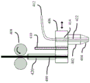
FIG. 10 is a schematic view of a three-dimensional printing system including a guide tube;
FIG. 11 is a photograph of a three-dimensional printing system including a guide tube;
fig. 12A is a schematic view of a shear cutting head with an optional index position;
fig. 12B is a schematic view of the shear cutting head of fig. 12A in a second indexed position;
FIG. 13 is a schematic view of a multi-nozzle printhead including shear cutting;
FIG. 14A is a schematic view of a nozzle;
FIG. 14B is a schematic view of a nozzle having a circular outlet;
FIG. 14C is a schematic view of another nozzle having a circular outlet;
FIG. 15A is a schematic cross-sectional view of a shut-off mechanism integrated with a nozzle tip;
FIG. 15B is a schematic cross-sectional view of a shut-off mechanism integrated with the nozzle tip of FIG. 14A rotated 90;
FIG. 15C is a bottom view of an embodiment of a shut off mechanism integrated with the nozzle tip;
FIG. 15D is a bottom view of an embodiment of a shut off mechanism integrated with the nozzle tip;
FIG. 16 is a schematic cross-sectional view of a shut-off mechanism integrated with the nozzle tip;
FIG. 17A is a schematic view of a three-dimensional printing system applying a compaction force during part formation;
FIG. 17B is a schematic of a continuous core reinforcing filament used in a printing system prior to deposition;
FIG. 17C is a schematic view of a continuous core reinforcing filament and surrounding bead of material after deposition using a compaction force;
FIG. 18A is a schematic view of a prior art nozzle;
FIG. 18B is a schematic view of a diverging nozzle;
FIG. 18C is a schematic view of the diverging nozzle of FIG. 18B shown in a feed-forward cleaning cycle;
FIG. 19A is a schematic view of a continuous core filament printed with a straight nozzle;
FIG. 19B is a schematic representation of raw tow prepreg printed with linear nozzles;
FIGS. 19C-19E are schematic illustrations of continuous core filaments stitched and printed with diverging nozzles;
FIG. 20A is a schematic view of a multi-material nozzle with a low friction cooling feed zone;
FIG. 20B is a schematic view of a slightly converging nozzle including a low friction cooling feed zone;
FIG. 21A is a schematic view of a prior art nozzle;
21B-21D illustrate nozzle geometries of various embodiments;
FIG. 22 is a schematic view of a drip resistant nozzle and pressure relief system;
FIG. 23A is a schematic view of a semi-continuous core wire positioned within a nozzle;
FIG. 23B is a schematic view of a semi-continuous core filament with overlapping strands located within a nozzle;
fig. 23C is a schematic view of a semi-continuous core filament with aligned strands located within a nozzle;
FIG. 24A is a schematic view of a multi-filament continuous core;
figure 24B is a schematic illustration of a semi-continuous core filament with offset strands;
figure 24C is a schematic of a semi-continuous core filament with aligned strands;
figure 24D is a schematic view of a semi-continuous core filament having aligned strands and one or more continuous strands;
FIG. 25 is a schematic illustration of a fill pattern using a semi-continuous filament core;
FIG. 26 is a schematic illustration of a plurality of printed layers formed by a three-dimensional printing system and/or process having different layers and different portions of the layers including different fiber directions;
FIG. 27A is a schematic illustration of a three-dimensional printing process for forming a part in a first orientation;
FIG. 27B is a schematic view of a fixture using the parts of FIG. 27A;
FIG. 27C is a schematic view of a three-dimensional printing process for forming a part on the part of FIG. 27A in a second orientation;
FIG. 28A is a schematic illustration of a three-dimensional printing process using a multi-axis system in a first orientation;
FIG. 28B is a schematic view of a component formed in another orientation of the part of FIG. 28A;
FIG. 29 is a schematic of a three-dimensional printing system using continuous core reinforcing filaments;
FIG. 30A is a schematic view of a part including a housing applied to a side using a three-dimensional printing process;
FIG. 30B is a schematic illustration of a part including a housing applied to the top and sides using a three-dimensional printing process;
FIG. 30C is a schematic view of a part including a housing that has been offset from an underlying support surface;
FIG. 30D is a schematic view of a part formed from a filler material;
FIG. 30E is a schematic view of a part formed with composite material extending inwardly from a corner and polymer filling the interior;
FIG. 30F is a schematic view of a part formed with composite material extending inward from a corner and polymer filling the interior;
FIG. 30G is a schematic view of a part formed with composite material extending inward from a corner and polymer filling the interior;
FIG. 31A is a schematic illustration of a airfoil formed from discrete subsections including fibers oriented in the same direction;
FIG. 31B is a schematic illustration of a airfoil formed from discrete subsections including fibers oriented in different directions;
FIG. 31C is a schematic view of an airfoil formed by discrete sub-portions and shells formed thereon;
FIG. 32 is a schematic view of a three-dimensional printing system including a print arm and an alternative printer head;
FIG. 33 is a schematic view of a multi-element printer head used in a printing system;
FIG. 34 is a schematic illustration of a stereolithography three-dimensional printing process including deposited reinforcing fibers;
FIG. 35 is a schematic illustration of a stereolithography three-dimensional printing process including deposited reinforcing fibers;
FIG. 36 is an illustrative view of a three-dimensional printed part including incorporated printed parts having different functions;
FIG. 37 is a schematic diagram of a three-dimensional printing system for forming multiple layers in a printed circuit board;
FIG. 38 is a schematic diagram of a three-dimensional printing system for filling various apertures in a printed circuit board with solder or solder paste;
FIG. 39 is a schematic view of the printed circuit board of FIG. 38 after forming vias and contact pads;
FIG. 40A is a schematic view of a printed part including an internal bore;
FIG. 40B is a schematic view of a printed part including internally formed reinforcement holes;
FIG. 40C is a schematic view of a printed part including internally formed reinforcement holes;
FIG. 41A is a schematic view of a composite part formed using a three-dimensional printing process;
FIG. 41B is a scanning electron microscope photograph of enhanced carbon fibers and vertically aligned carbon nanotubes;
FIG. 42 is a schematic view of a circuitous route impregnation system;
FIG. 43A is a schematic of an afferent material with a blended tow;
FIG. 43B is a schematic illustration of the material of FIG. 43A after impregnation;
FIG. 44A is a schematic view of a deflection roller impregnation system;
FIG. 44B is a schematic view of the roll impregnation system of FIG. 44A in an optional load configuration;
FIG. 45 is a schematic view of an impregnation system incorporating a vacuum impregnation nozzle;
FIG. 46 is a schematic view of a dipping system integrated with a print nozzle;
FIG. 47 is a schematic view of a print nozzle including a circuitous path immersion system;
FIG. 48 is a schematic view of a multi-nozzle three-dimensional printer;
FIG. 49A is a schematic illustration of a co-extrusion process for forming a continuous core reinforcing filament and an optional outer coating;
FIG. 49B is a schematic illustration of a starting material used in the process shown in FIG. 49A;
FIG. 49C is a schematic illustration of a starting material used in the process shown in FIG. 49A;
FIG. 49D is a schematic illustration of one embodiment of a material after impregnation using the process shown in FIG. 49A;
FIG. 49E is a schematic view of one embodiment of a material after impregnation using the process shown in FIG. 49A;
FIG. 49F is a schematic illustration of one embodiment of a material after impregnation using the process shown in FIG. 49A;
FIG. 49G is a schematic of an embodiment of a material including an optional overcoat layer using the process shown in FIG. 49A;
FIG. 49H is a schematic representation of one embodiment of a material including an optional overcoat layer using the process shown in FIG. 49A;
FIG. 49I is a schematic illustration of an embodiment of a material including an optional overcoat layer using the process shown in FIG. 49A;
FIG. 50A is a schematic representation of a co-extrusion process for forming a continuous core reinforcing filament and an optional outer coating;
FIG. 50B is a schematic illustration of a starting material used in the process shown in FIG. 50A;
FIG. 50C is a schematic illustration of a starting material used in the process shown in FIG. 50A;
FIG. 50D is a schematic illustration of the starting material after deployment using the process shown in FIG. 50A;
FIG. 50E is a schematic illustration of one embodiment of a material after impregnation using the process shown in FIG. 50A;
FIG. 50F is a schematic illustration of one embodiment of a material after forming using the process shown in FIG. 50A;
FIG. 50G is a schematic view of one embodiment of a material after forming using the process shown in FIG. 50A;
FIG. 50H is a schematic view of one embodiment of a material after forming using the process shown in FIG. 50A; and
FIG. 50I is a schematic representation of one embodiment of a material including an optional overcoat layer using the process shown in FIG. 50A.
Detailed Description
The present inventors have recognized that one of the fundamental limitations associated with typical additive manufacturing methods is the strength and durability of the resulting parts. For example, fuse fabrication results in parts that exhibit lower strength than comparable injection molded parts. While not wishing to be bound by theory, the reduction in strength is due to a weaker bond (also bubbles and voids) between adjacent strips of deposited material as compared to a continuous and substantially void-free material formed, for example, in injection molding. The present inventors have also recognized that prepreg composite construction methods that use sheet-based techniques to form three-dimensional parts are time consuming and difficult to handle resulting in high costs. Furthermore, bending such a sheet around a curve, such as a circle, may cause the fibers to overlap, buckle, and/or twist, resulting in undesirable soft spots in the resulting component. As regards the three-dimensional printers using "tow prepregs" or "tows" comprising reinforcing fibres and resins, the present inventors have noted that the deposition materials of the prior art are generally difficult to load in the machine and further difficult to feed through the print head due to the very flexible and often high friction (viscous) initial state. In addition, these raw materials tend to entrain air and include air gaps. Thus, without a subsequent vacuum heating step, the resulting part also contains porosity and is substantially weaker than a conventional composite part constructed under vacuum. Thus, the additional steps associated with making tow prepreg slow the printing process and result in the entrainment of ambient air.
Due to the limitations associated with typical three-dimensional printing systems as described above, the present inventors have recognized a need to improve the strength of three-dimensional printed composites. Furthermore, there is a need for additive manufacturing construction techniques that allow for greater speeds; removing or preventing air entrainment in the deposited material; reducing the need for a subsequent vacuum step; and/or proper and accurate extrusion of the composite core material. The present inventors have also recognized that it would be desirable to provide the ability to deposit concave fibers and/or to construct discrete features on a surface or composite shell.
In view of the above, the present inventors have recognized benefits associated with providing a three-dimensional printing system that prints structures using a substantially non-porous pre-impregnated (prepreg) material or is capable of forming a substantially non-porous material for use in a deposition process. For example, in one embodiment, a three-dimensional printer uses continuous core reinforcing filaments comprising a continuous multifilament core material having a plurality of continuous strands pre-impregnated with thermoplastic resin that has been "wicked" into the strands, and such pre-impregnated material is then formed into a three-dimensional structure. The material is not "green" due to the thermoplastic resin that has wicked into the strands, and is rigid, low friction, and substantially non-porous. In another embodiment, a solid continuous core is used and the thermoplastic resin wets the solid continuous core such that the resulting continuous core reinforcing filament is also substantially void-free. In addition, embodiments are also contemplated in which a semi-continuous core is used in which a core extending through the length of the material is segmented into multiple portions along the length. Such embodiments may include a solid core or a plurality of individual strands evenly spaced apart from one another or overlapping without limitation of the present disclosure. In either case, such core materials may also be pre-impregnated or wetted, as described above. The substantially non-porous material may have a percentage of porosity of less than about 1%, 2%, 3%, 4%, 5%, 10%, 13%, or any other suitable percentage. For example, the non-porous material may have a percentage of porosity of about 1% to 5%. Further, parts printed using the above-described non-porous material may also exhibit a percent porosity of less than about 1%, 2%, 3%, 4%, 5%, 10%, or 13% due to the processing methods described below.
While prepreg materials are discussed above, in one embodiment, a solid continuous core filament may be selectively combined with resin within the nozzle outlet. While not wishing to be bound by theory, due to the regular and well-defined geometry of the solid core, the resin uniformly coats the core and the resulting deposited composite is substantially void-free.
In this application, the core reinforcing filaments are described as being impregnated or wetted. For example, a solid core may be wetted with a matrix material, or a multifilament core may be impregnated or fully wetted with a matrix material. However, for the purposes of this application, a filament comprising a core that has been impregnated is understood to mean a filament comprising a core that has been sufficiently impregnated and/or wetted with a matrix material. The skilled person will understand how this will be interpreted as an application in which the core material is a solid core.
In addition to the above, core reinforcements are described in this application. For specific embodiments and examples, continuous and/or semi-continuous cores may be described for exemplary purposes. However, it should be understood that a continuous and/or semi-continuous core may be used in any particular application and the disclosure is not limited in this manner. Further, with respect to the core reinforcement material, the core may be located inside the filament or the core material may extend to the outer surface of the filament, and the disclosure is not limited in this manner. Further, it should be understood that the core reinforcement material also includes reinforcement provided by materials such as optical materials, fluid conducting materials, electrically conducting materials, and any other suitable materials, and the disclosure is not so limited.
In another embodiment, the present inventors have recognized benefits associated with providing a continuous or semi-continuous core combined with Stereolithography (SLA), Selective Laser Sintering (SLS), and other three-dimensional printing processes, wherein a matrix in liquid or powder form is used to form a substantially void-free part exhibiting enhanced strength. The above-described embodiments may help reduce or eliminate the need for subsequent vacuum steps and improve the strength of the resulting printed structure by helping to reduce or eliminate the presence of voids within the final structure.
In addition to improving strength due to elimination of voids, the present inventors have recognized that the current limitation of laying down individual strands in a three-dimensional printing process can be used as an advantage in the fabrication of composite structures. For example, the direction of the reinforcement material deposited during printing within the structure may be controlled within specific layers and portions of layers to locally and generally control the directional strength of the composite structure. Thus, increased directionality within the structure may provide increased part strength at desired locations and directions to meet specific design requirements. The ability to easily tailor the directional strength of a structure at a particular location may allow for the provision of lighter and stronger resulting parts.
In one embodiment, it may be desirable to include a shut-off mechanism for a three-dimensional printing system. Such a shut-off mechanism may be used to provide a selective stop to deposit a desired length of material. Otherwise, the printing process is not easily terminated because the deposited material is still connected to the material (e.g., a continuous core) within the material extrusion nozzle. The shut-off mechanism may be located at the outlet of the associated printer nozzle or may be located upstream of the outlet. Further, in some embodiments, the severing mechanism is located between the feed mechanism of the core material and the outlet of the nozzle. Regardless of the particular make-up and location, however, the severing mechanism enables the three-dimensional printing system to quickly and easily deposit a desired length of material in a desired direction at a particular location. In contrast, systems that do not include a shut-off mechanism continuously deposit material until the material is exhausted or is manually shut off. This limits the complexity of the parts that can be manufactured, the speed of the printing process, and the ability to deposit material comprising a continuous core in a particular direction. Depending on the implementation, the severing mechanism may also interrupt printer feed by blocking the nozzle or preventing the feed mechanism from applying force or pressure to a portion of the material downstream of the severing mechanism. While in certain instances it may be desirable to include a severing mechanism for a three-dimensional printer, it should be understood that the embodiments described herein may or may not use a severing mechanism, and the disclosure is not limited in this manner. Further, the severing mechanism may also be used with embodiments that do not include a continuous core.
It should be understood that the substantially nonporous material described herein may be made in any manner. However, in one embodiment, the material is formed by applying varying pressures and/or forces in different directions during the material formation process. For example, in one embodiment, the polymer or resin and the multi-strand core comprising a plurality of cores of reinforcing fibers are mixed prior to being fed into the system. The system then heats the material to the desired viscosity of the polymer resin and applies varying pressure and/or force in alternating directions of the blended tow prepreg to help facilitate adequate impregnation of the fibers of the tow prepreg with the polymer or resin. This may be achieved by using a smooth circuitous path comprising a plurality of bends through which the raw tow prepreg passes, or it may correspond to a plurality of offset rollers which change the direction of the tow prepreg as it passes through the system. As the tow prepreg travels a circuitous path, the varying forces and pressures help to fully impregnate the polymer into the core and form a substantially nonporous material. Although blended tow prepregs comprising individual strands of reinforcing fibers and polymeric resin are described above, embodiments are also contemplated in which the solid core and/or plurality of reinforcing fibers are blended with polymer particles or immersed in a liquid polymer or resin, followed by the above process. In addition to the above, after impregnating the core with the polymer, a substantially non-porous material may be fed through the forming nozzle to provide the desired shape. The nozzle may be of any suitable shape, including circular, oval, square or any other desired shape. Although a continuous core is described above, embodiments are contemplated in which a semi-continuous core is used. In addition, this formation process can be performed at ambient conditions, or under vacuum, to further eliminate the presence of pores within the substantially non-porous material.
In some embodiments, it may be desirable to provide a smooth outer coating on a tow prepreg corresponding to the substantially non-porous material described above. In such an embodiment, a substantially nonporous material formed as described above or in any other suitable process is coextruded with the polymer through a suitably shaped nozzle. As the substantially non-porous material and polymer are extruded through the nozzle, the polymer forms a smooth outer coating around the substantially non-porous material.
The materials used in the presently described three-dimensional printing process can be incorporated into any suitable combination of materials. For example, suitable resins and polymers include, but are not limited to, Acrylonitrile Butadiene Styrene (ABS), epoxy, vinyl, nylon, Polyetherimide (PEI), Polyetheretherketone (PEEK), polylactic acid (PLA), liquid crystal polymers, and various other thermoplastic materials. The core may also be selected to provide any desired properties. Suitable core filaments include those that impart desired properties, such as structural, conductive (electrical and/or thermal), insulative (electrical and/or thermal), light and/or fluid transport aspects. Such materials include, but are not limited to, carbon fiber, aramid fiber, fiberglass, metals (e.g., copper, silver, gold, tin, steel), fiber optics, and flexible tubing. It should be understood that the core wire may be provided in any suitable size. In addition, multiple types of continuous cores may also be used in a continuous core reinforcing filament to provide multiple functions, such as electrical and optical properties. It should also be understood that one material may be used to provide multiple properties of the core reinforcement filament. For example, steel cores may be used to provide structural properties as well as electrical conductivity.
In some embodiments, in addition to selecting the material of the core reinforcing filaments, it is desirable to provide the ability to use core reinforcing filaments with different resins to enhance the core ratio to provide different properties in different portions of the part. For example, low resin fillers may be used in the internal structure of the part to maximize the strength-to-weight ratio (e.g., 20% resin by cross-sectional area). However, on the outer cosmetic surface of the part, the higher 90% of the resin consumed may be used to prevent possible printing of individual fiber strands through the underlying core or cores. Further, in some embodiments, the consumable material may have zero fiber content and be resin only. Thus, it should be understood that any suitable percentage of resin may be used.
The core reinforcing filaments may also be provided in various sizes. For example, the continuous or semi-continuous core reinforcing filaments may have an outer diameter greater than or equal to about 0.001 inches and less than or equal to about 0.4 inches. In one embodiment, the filaments are greater than or equal to about 0.010 inches and less than or equal to about 0.030 inches. In some embodiments, it is also desirable that the core reinforcing filaments have a substantially constant outer diameter along their length. Depending on the particular embodiment, different smoothness and tolerances regarding the outer diameter of the core reinforcing wire may be used. While not wishing to be bound by theory, a constant outer diameter may help provide a constant material flow rate and consistent performance in the final part.
As explained in more detail below, the ability to selectively print electrically conductive, optically conductive, and/or electrically conductive fluid cores within a structure allows the structure of the desired components to be provided in the structure. For example, a continuous core of electrically and optically conductive material may be used to construct strain gauges, optical sensors, traces, antennas, wiring, and other suitable components. The core of the current carrier may also be used to form components such as fluid passages and heat exchangers. The ability to form functional components on or within a structure provides a number of benefits. For example, the three-dimensional printing process and apparatus described may be used to fabricate printed circuit boards that are integrally formed in a structure; wiring and sensors integrated in the chassis or planar fuselage of the automobile; and motor cores with integrated windings, to name a few.
Specific embodiments of the disclosed materials and three-dimensional printing processes are now described with reference to the drawings.
Fig. 1 shows an embodiment of a three-dimensional printer that uses continuous strands of composite material to construct a structure. In the embodiment shown, the continuous strand of composite material is a continuous core reinforcing filament 2. The continuous core reinforcing filaments 2 are substantially void-free tow prepregs and comprise a polymer 4 coating or impregnating an inner continuous core 6. According to a particular embodiment, the core 6 may be a solid core or it may be a multifilament core comprising a plurality of strands.
The continuous core reinforcing filaments 2 are fed through a heated nozzle, such as an extrusion nozzle 10. As the continuous core reinforcing filament is fed through the extrusion nozzle, it is heated to a preselected extrusion temperature. The temperature may be selected to achieve any number of resulting properties, including but not limited to viscosity of the extruded material, adhesion of the extruded material to the underlying layer, and the resulting surface finish. While the extrusion temperature may be any suitable temperature, in one embodiment, the extrusion temperature is above the melt temperature of polymer 4, but below the decomposition temperature of the resin and the melting or decomposition temperature of core 6. Any suitable heater may be used to heat the nozzle, such as a band heater or a coil heater.
After heating in the heated extrusion nozzle 10, the continuous core reinforcing filaments 2 are extruded onto a build impression tray 16 to build the continuous layer 14, forming the final three-dimensional structure. The position of the heated extrusion nozzle 10 relative to the build platen 16 during deposition may be controlled in any suitable manner. For example, the position and orientation of the build platen 16 or the position and orientation of the heated extrusion nozzle 10 may be controlled by the controller 20 to deposit the continuous core reinforcing filaments 2 at desired positions and directions, the present disclosure is not limited to any particular control method. In addition, any suitable movement mechanism may be used to control the nozzles or to configure the platen, including gantry systems, robotic arms, H-stands, and other suitable movement systems. The system may also include any suitable position and displacement sensors to monitor the position and movement of the heated extrusion nozzle relative to the build platen and/or the part being built. These sensors may then provide sensed position and movement information to the controller 20. The controller 20 may use the sensed X, Y, and/or Z axis position and movement information to control subsequent motion of the heated extrusion head or platen. For example, the system may include a range finder, a displacement sensor, a distance integrator, an accelerometer, and/or any other sensing system capable of detecting the position or movement of the heated extrusion nozzle relative to the build platen. In one embodiment, as shown in the figures, a laser range finder 15 or other suitable sensor is used to scan the section before the heated extrusion nozzle to correct the Z-height of the nozzle or the required fill volume to match the desired deposition profile. Such measurements may also be used to fill in voids detected in the part. In addition, the rangefinder 15 or another rangefinder may be used to measure the part after the material is extruded to confirm the depth and position of the deposited material.
Depending on the embodiment, the three-dimensional printer includes a severing mechanism 8. Cutting mechanism 8 advantageously allows the continuous core reinforcing filaments to be cut automatically during printing without the need for manual cutting or tail formation, as described in more detail below. By severing the continuous core reinforcing filaments during deposition, individual features and portions may be formed on the structure and the directionality of the deposited material is controlled in multiple portions and layers, which results in multiple benefits, as described in more detail below. In the embodiment shown, the severing mechanism 8 is a severing blade associated with a backing plate 12 located at the nozzle outlet, although other locations are possible. Although one embodiment of a severing mechanism including a severing blade is shown, other types of severing mechanisms are possible as described in more detail below, including but not limited to a laser, high pressure air, high pressure fluid, a shearing mechanism, or any other suitable severing mechanism. In addition, the particular severing mechanism may be suitably selected for the particular specific feed used in the three-dimensional printer.
Fig. 1 also shows a plurality of optional secondary print heads 18, which in some embodiments are used in a three-dimensional printer. The secondary print head 18 can be used to deposit ink or other suitable optional coatings on the surface of the three-dimensional printed part. In one embodiment, the secondary printhead is similar to existing inkjet printers. Such a print head can be used to print photographic quality drawings and images on parts during the manufacturing process. For such a printing process, the print head may use an ultraviolet resistant resin. Alternatively, the print head may be used to print a protective coating on the part. For example, the print head may be used to provide a uv resistant or scratch resistant coating.
FIG. 2 shows a schematic flow diagram of a three-dimensional printing process using the system and controller shown in FIG. 1. First, at 102, a continuous core reinforcement wire is provided. The continuous core reinforcing filaments are then fed to heated extrusion nozzles, at 104 and 106, and heated to a desired temperature that is greater than the melting temperature of the resin and less than the melting temperature of the continuous core. Then, in 108, the three-dimensional printer senses the position and movement of the heated extrusion nozzle relative to the build platen or part. After the heated extrusion nozzle is positioned and moved, the nozzle is moved to the desired location, and at 110, the continuous core reinforcing filaments are extruded at the desired location and along the desired path and direction. Embodiments are also contemplated in which movement of the platen or part relative to the nozzle is configured. After the desired termination point is reached, the continuous core reinforcing filaments are cut at 112. The controller may then determine whether the three-dimensional part is complete. If the printing process is not complete, the controller may return to 108 during which the current position and movement of the nozzle is sensed and then the next segment of continuous core reinforcing wire is deposited. If the part is complete, the final part may be removed from the build platen. Optionally, at 118, an optional coating may be deposited on the part using a secondary print head to provide a protective coating and/or apply a digital or image to the final part. It should be understood that the steps described above may be performed in a different order than that described. Further, in some embodiments, additional steps may be used and/or omitted, and the present disclosure is not limited to the process shown in fig. 2.
Fig. 3A-3E show various constructed embodiments of the continuous core reinforcing filaments 2. In addition to the specific core construction, the material is processed to be substantially void-free, which aids in the bonding of the various layers of the final structure and the resulting strength.
Fig. 3A and 3B show cross-sectional views of continuous core reinforcing filaments comprising a solid core 6a embedded in a surrounding polymer 4 or resin. Substantially no voids are present in the polymer or between the polymer and the solid core. Fig. 3A shows a core reinforcing filament comprising a cross section of a larger proportion of polymer. Figure 3B shows a cross section of a larger solid core and a corresponding larger proportion of reinforcing core material. It should be understood that any suitable ratio of continuous core area to polymer area may be used. Furthermore, while not wishing to be bound by theory, materials with a greater proportion of polymer may result in a smoother surface finish and better adhesion between layers. Conversely, larger proportions of continuous core filament may be used to increase the strength and weight ratio of the final construction component, as the fibrous material constitutes the bulk strength of the composite material and is present in larger proportions. Larger cores may also be advantageous when the core is made of copper or other suitable electrically or optically conductive material, as a large core may be required to increase the conductivity of the deposited material.
Fig. 3C and 3D show another embodiment in which the core material of the continuous core reinforcing filaments 2 is a continuous multifilament core material 6b surrounded and impregnated by a polymer 4 wicking into the multifilament core cross section. Fig. 3C shows a smaller proportion of multifilament core material 6b surrounded and impregnated by polymer 4. Fig. 3D shows an embodiment with a very small amount of resin and a large proportion of multifilament core material 6b, such that the multifilament core material fills almost the entire cross section. In this embodiment, the polymer 4 behaves more like an adhesive impregnated into the multifilament core material 6b holding it together. Similar to the solid core described above, any suitable ratio of resin to multi-filament core material may be used to provide the resulting continuous core reinforcing filaments 2 with a selected strength, surface finish, conductivity, adhesion, or other desired property.
Figure 3E shows a deformation of the continuous multifilament core. In this embodiment, the continuous core reinforcing filaments 2 still comprise a continuous multi-filament core 6b surrounded and impregnated by the polymer 4. However, the core also comprises one or more secondary strands of core material 6c and 6 d. These secondary core materials may be optically, electrically, thermally, electrically, or some combination of the above. These secondary core materials may be used to conduct power, signals, heat and fluids as well as for structural health monitoring and other desired functions.
In order to avoid the above-mentioned entrainment of voids within the core reinforcing filaments 2, the polymeric material is treated so that the molten polymer or polymer resin wicks into the reinforcing fibers during the initial production of the material. In some embodiments, the polymer wicks substantially to the entire cross-section of the multi-filament core, which helps to provide a substantially non-porous material. To make the desired core reinforcing filaments, the core reinforcing filaments may be pretreated with one or more coatings to activate the surface, followed by exposure to one or more environmental conditions, such as temperature, pressure, and/or chemical agents (e.g., plasticizers) to aid in the wicking of the polymer or resin to the cross-section of the multifilament core without the formation of any voids. In some embodiments, this process may be performed prior to entering the feed head of the three-dimensional printer. However, in other embodiments, the core-stiffened wire is formed on a completely separate machine prior to the printing process and is provided as a consumable printed material. Because the subsequent deposition process need not be run at a temperature high enough to wet the core material with polymer or resin, the deposition process can be run at lower temperatures and pressures than would be required for a typical system. Although the above-described method is applicable to both solid and multi-filament cores, it is more advantageous to apply the method to multi-filament cores due to the difficulty associated with wicking into multi-filament cores without forming voids. In addition, by forming the core reinforcing filaments individually or prior to introduction to the nozzle, the width and proportion of the material can be tightly controlled, resulting in a more constant feed rate of the material as it is fed to the three-dimensional printer.
In contrast to the above-described materials, which are generally formed without voids, the prior art has used an "unprocessed" deposition process, including the use of reinforcing fibers that may have themselves been impregnated with resin or molten polymer during the extrusion process and wicked with a multi-filament core. To do this, the resin or polymer is heated substantially above the melting point so that the viscosity is low enough to allow the resin or polymer to wick into the reinforcing fibers. This process may be assisted by a set of rollers that apply pressure to the material to aid in wicking to the reinforcing fibers. However, due to the arrangement of the rollers and the temperature of the tow prepreg as it exits the rollers, this process typically results in voids being entrained in the material prior to final formation. After the resin or polymer is wicked into the reinforcing fibers, the resulting "tow prepreg" or "tow" is typically cooled to just above the melting point prior to extrusion. However, this process is typically performed in air combined with air present in the material when inserted into the nozzle, resulting in ambient air being entrained in the material, as described in more detail below.
This wicking process in the extrusion process of a typical tow prepreg is shown in figure 4. As shown, prior to the wicking and extrusion process, the raw tow prepreg 22 includes a plurality of raw matrix resin particles or filaments 24, mixed with a plurality of reinforcing fibers 28 and ambient air 26. As shown, the reinforcing fibers 28 are randomly distributed throughout the cross-section. As the tow prepreg 22 passes through the heating zone 30 of the extrusion nozzle, the material is heated to induce wetting of the fibres and formation of the cured resin 32. Ambient air 26 is also entrained in the tow prepreg, forming air gaps 34. These entrained air gaps 34 are then buried in the resulting printed part. In addition, the air gap 34 may result in non-bonded portions 36 of the fibers. Since these unbonded portions of the reinforcing fibers are not in contact with the polymer, the resulting composite is weak at this location. In contrast, the continuous core reinforcing filaments in the illustrative embodiments shown in fig. 3A-3E are substantially non-porous, and in at least some embodiments, the core is centrally located within the surrounding resin. While not wishing to be bound by theory, this results in a stronger, more uniform material and resulting part.
Although the presently described three-dimensional printer system is primarily directed to the use of pre-impregnated or wetted core reinforcement filaments as described herein, in some embodiments, the three-dimensional printer system may use a material similar to the raw blended tow pre-preg 22 shown in fig. 4. However, as noted above, it is desirable to avoid the formation of entrained air gaps during solidification of the material within the nozzle. One possible way to avoid air gap formation in the deposited material is to provide a vacuum within the nozzle. By providing a vacuum within the nozzle, no air is entrained within the tow prepreg as it is heated and cured within the nozzle. Thus, in some embodiments, the nozzle is configured to allow simultaneous introduction of a continuous raw material comprising a solid or multi-filament core under vacuum. The continuous green material may then be heated while under vacuum to a suitable temperature above the melting temperature of the resin or polymer within the continuous green material to promote wicking of the resin or polymer into the core, thereby producing a substantially nonporous material. Another approach is to use a circuitous path, which may be provided by offset rollers or other configurations as described below, to mechanically treat the entrained air. Optionally, vacuum may also be applied in combination with mechanically removing bubbles through a circuitous path.
In addition to the materials used to print the three-dimensional part, the particular nozzle used to deposit the core reinforcing filaments also has an effect on the performance of the final part. For example, the geometry of an extrusion nozzle used in a typical three-dimensional printer is a convergent nozzle, see fig. 5. Convergent nozzles used in typical three-dimensional printers typically have a stock material with a diameter of about 0.060 inches to 0.120 inches (1.5mm to 3 mm). The stock is extruded through a nozzle typically necked to a tip orifice of about 0.008 inch to 0.016 inch (0.2mm to 0.4 mm). However, such nozzles may not be desirable for feedstocks comprising continuous cores for the following reasons.
While not wishing to be bound by theory, the constrained geometry causes the fluid polymer matrix material to accelerate relative to the continuous core as the feedstock is fed to the converging nozzle. Furthermore, the matrix and the core typically have different coefficients of thermal expansion. Since the matrix material is a polymer, it generally has a large coefficient of thermal expansion. Therefore, as the matrix material is heated, the matrix material is accelerated with respect to the fibers due to a large expansion of the matrix material in the closed space of the convergent nozzle. The acceleration of the matrix material relative to the fibers results in a matrix material flow velocity V near the nozzle inletmatrixLess than the flow velocity V of the fibrous materialfiber. However, the flow velocity V of the matrix material at the outletmatrixEqual to the flow velocity V of the fibrous materialfiber. As shown, the mismatched speed of the matrix material and fibers within the converging nozzle may cause the fibers to collect within the nozzle during the deposition process. This can lead to clogging and it is difficult to control the uniformity of the deposition process. It should be understood that while the difficulties associated with convergent nozzles have been described above, convergent nozzles may be used with the embodiments described herein, and the disclosure is not limited in this manner.
In view of the above, it would be desirable to provide a nozzle geometry that is capable of maintaining the individual strands of multifilament core material 6b or other suitable core and the matched velocity of the polymer 4 or other matrix material throughout the nozzle, resulting in a given matrix and core combination. For example, fig. 6A shows a diverging nozzle 200 with an increased nozzle diameter that matches the thermal expansion of the matrix material. As shown, the nozzle 200 includes an inlet 202 having a diameter D1, a portion 204 having an increased diameter, and an outlet 206 having a diameter D2 that is greater than the diameter D1. While not wishing to be bound by theory, by matching the nozzle diameter to the expected expansion of the matrix material within the nozzle, the matrix and continuous core reinforcing filaments maintain substantially the same velocity as each other throughout the nozzle. Thus, the linear extrusion rates of the matrix material and the continuous core are the same, and the continuous core does not accumulate within the nozzle.
In addition to the above, in some embodiments, the matrix material and the continuous core have relatively low coefficients of thermal expansion (e.g., carbon fibers and liquid crystal polymers). In such embodiments, because the matrix material and the reinforcement fibers are at substantially the same size, the nozzle 200 may include an inlet 202 and an outlet 206 having substantially the same diameter D3, see fig. 6B. Thus, while some nozzle designs may have a diverging geometry, in some embodiments, the nozzle geometry may be substantially linear and may have substantially similar inlet and extrusion zones.
In addition to controlling the relative sizes of the inlet and outlet of the nozzle, the nozzle 200 may also include a circular nozzle outlet 208, see fig. 6C. The circular nozzle outlet 208 may have any suitable form and size. For example, the circular nozzle outlet 208 may be embodied by an outwardly extending lip, chamfer, square mesh, circular arc, or any other suitable geometry to provide a smooth transition from the nozzle outlet. While not wishing to be bound by theory, a circular nozzle outlet that provides a smooth transition from the nozzle bore may help avoid applying excessive stress and/or scraping to the web when extruded from the nozzle 200. This smooth transition provided by the circular nozzle outlet may help avoid fracturing the continuous core wire during deposition.
Fig. 7 illustrates a possible disadvantage of printing continuous core reinforcing filaments without an integrated cutter in the print head. As shown, the printhead 300 forms a part 302 and is shown as the last part to deposit a material layer 304. Since the usual fuse fabrication (FFF) technique, also known as Fused Deposition Modeling (FDM), will print close to the underlying part and often touch the top of the extruded plastic, there is little or no room to introduce an external cutting mechanism therein. In fact, without a near zero thickness blade, the print head would need to print label end excess 306 that is not specified in the part, enabling a separate cutting mechanism or person to cut the continuous core and terminate the printing process. However, this leaves an undesirable label end excess 306 at each fiber termination point. As shown in fig. 7, a number of internal features, such as a rigid mounting boss 308, may have tag end overhangs 306 in various layers within the boss. In view of the above, the integrated severing mechanism may require less post-processing and allow the machine to simply print the desired part with smaller and fewer label end overhangs. Further, in some embodiments, as described in more detail below, the severing mechanism may eliminate the presence of a label end overhang.
Fig. 8 shows two embodiments of a cutting mechanism for use with a three-dimensional printer. As shown, a suitable feed (in this example, continuous core reinforcing wire 2a, although other suitable filaments may be used) is taken from a reel 38 and passed through a feed mechanism, such as a drive roller 40 and an idler roller 42. The drive roller 40 or any other suitable feed mechanism is constructed and arranged to apply a downstream directed force to the continuous core reinforcing wire 2a in this embodiment. Thus, the continuous core reinforcing filaments 2a may be at a temperature such that they are in a solid or semi-solid state when the force is applied. For example, the force may be applied to the material at room temperature, below the glass transition temperature of the material, at room temperature below the glass transition temperature, or at any other suitable temperature at which the material is capable of supporting the applied force. The applied downstream force causes the continuous core reinforcing filaments 2a to enter and be extruded from the heated nozzle 10, thereby building a three-dimensional part. Although a drive roller has been shown, it should be understood that any suitable feed mechanism may be used.
In the first embodiment, a cutting mechanism 8a such as a blade is located at the outlet of the heated extrusion nozzle 10. This configuration allows actuation of the severing mechanism to completely sever the deposited strip by acting on the inner continuous core. Further, in some embodiments, the nozzle pressure is maintained during severing, and the severing blade is actuated to sever the inner strands and prevent further extrusion of the continuous fiber reinforced material and prevent dripping by physically blocking the nozzle outlet. Thus, the severing mechanism enables the continuous core reinforcing filaments and unreinforced material to be deposited in precisely selected lengths as compared to conventional three-dimensional printers.
In the second illustrated embodiment, integrated with the same system, the shut-off mechanism 8b is located upstream of the nozzle outlet. More specifically, the severing mechanism 8b may be located in the hot end of the nozzle, or further upstream before the continuous core reinforcing filaments are heated. In some embodiments, the shut off mechanism 8b is located between the nozzle outlet and the feed mechanism 40. Such an embodiment may allow for the use of a smaller gap between the nozzle outlet and the part, as the shut-off mechanism need not be accommodated in the space between the nozzle outlet and the part. Depending on the particular location, severing mechanism 8b may sever the continuous core filament and surrounding matrix while at a temperature below the melting or softening temperature, and in some embodiments, below the glass transition temperature. While not wishing to be bound by theory, cutting the continuous core reinforcing filaments below the melting, softening, and/or glass transition temperature of the polymer may reduce the tendency of the resin to stick to the blades, which may reduce machine clogging. Furthermore, the shut-off when the resin or polymer is below the melting point may facilitate more accurate metering of the deposited material. The cut location along the continuous core reinforcing filament may be selected to eliminate the presence of tag end overhang in the final part, thereby facilitating the formation of multiple individual features.
As shown, the downstream portion 2b of the continuous core reinforcing filaments may be severed from the upstream portion 2a of the continuous core reinforcing filaments by an upstream severing mechanism 8 b. By maintaining a close fit between the feed material and the guide tube in which the feed material resides, the downstream portion 2b of severed strands may still be pushed through the machine of the upstream portion 2a driven by the drive roller 40 or any other suitable feeding mechanism. While not wishing to be bound by theory, the previously deposited and cooled material also adheres to the previously deposited layer and the continuous core reinforcing filaments 2b are pulled from the heated extrusion nozzle 10 as the print head, which applies force to the continuous core at the downstream portion of the severing strand, moves relative to the part. Thus, a combination of upstream forces from the feed mechanism and downstream forces conveyed through the continuous core may be used to deposit a severing member of material. In addition, the location of the cut along the continuous reinforcing core may be selected to eliminate the presence of tag end overhang in the final part.
While embodiments including an integrated cleaving mechanism have been described above, embodiments that do not include a cleaving mechanism are also possible, and the disclosure is not limited in this manner. For example, embodiments may be used in which the parts are printed in a continuous string, such that termination of the continuous material is not necessary. In one such embodiment, the three-dimensional printer may not be able to achieve fiber termination, and therefore will print a length of material until the part is complete, the material is used up, or the user cuts the deposited material.
Although cutting the continuous fiber reinforcement material helps eliminate the presence of tag end overhangs, it is also desirable to prevent bending of the material to help ensure uniform deposition and prevent machine jams. While not wishing to be bound by theory, the stiffness of a material is proportional to the square of the diameter of the material. Thus, a continuous material having a large diameter is fed into the inlet of the nozzle as shown without the need for as much support as possible. However, as the diameter of the web decreases, additional features may be necessary to ensure that the web and any continuous core wire contained therein do not bend. For example, as explained in more detail below, a close-fitting guide tube may be used in combination with an inlet or guide tube that positions the feed mechanism proximate to the nozzle to help prevent material bending. Thus, in one embodiment, the feed mechanism may be located less than about 20 diameters, 10 diameters, 8 diameters, 6 diameters, 5 diameters, 4 diameters, 3 diameters, 2 diameters, 1 diameter, or any other suitable distance from the guide tube or inlet to the nozzle.
In addition to preventing buckling, in some embodiments, the maximum pulling or dragging force applied to the deposited reinforcing fibers is limited to prevent the printed part from being pulled from the corresponding build platen or to provide the desired amount of stretch of the continuous core. The force limit may be provided in any number of ways. For example, a one-way locking bearing may be used to limit the drag force. In such embodiments, driving the motor may turn the drive wheel via the one-way locking bearing such that rotation of the motor drives the wheel and extrudes material. If the material is dragged beyond the drive speed of the drive wheel, the one-way bearing may slip, allowing additional material to be pulled through the feed mechanism and nozzle, effectively increasing the feed rate to match the head travel speed, while also limiting the drive force such that it is less than or equal to the preselected limit. The drag force may also be limited using a clutch with built-in slip commensurate. Alternatively, in another embodiment, the normal force and coefficient of friction of the drive wheel and idler wheel may be selected to allow the web to be pulled through the feed mechanism above a certain drag force. Other methods of limiting the force are also possible. In another environment, an AC induction motor or a dc motor switched to an "off" position (e.g., which may correspond to a small resistance being applied to the motor terminals or opening the motor terminals depending on the embodiment) may be used to allow the filament to be pulled from the printer. In such embodiments, the motor may be allowed to freewheel when a drag force above a desired force threshold is applied to allow the filament to be pulled from the printer. In view of the above, the feed mechanism is constructed in some form or manner so that the filament can be pulled from the printer nozzle when the drag force applied to the filament is greater than a desired threshold force. Further, in some embodiments, a feed mechanism may be incorporated into the sensor and controller loop to provide feedback control of the deposition rate, printer head speed, and/or other suitable control parameters based on the tension of the filament.
As described above, a printer system configured to allow a filament to be drawn from a printer nozzle may be used in a variety of ways. However, in one embodiment, the printing system draws the filament out of the printer nozzle along a straight line print section. In such an action, the printer head may be displaced at a desired rate and the deposited material adhering to the preceding layer or printing surface will apply a drag force to the filament within the print nozzle. Thus, the filament will be pulled from the printing system and deposited onto the part. The printing system extrudes and/or pushes deposited filaments onto the part or surface as printing is performed along the curve and/or corner. Of course, embodiments are also contemplated in which the filament is not pulled from the printing system during operation and/or in which the filament is pulled from the printer head in curves and/or corners.
The presently described three-dimensional printing methods using continuous core reinforcing filaments also enable bridging of large air gaps that previously could not be spanned by a three-dimensional printer. While not wishing to be bound by theory, the deposition of drawn continuous core reinforcing filaments comprising an unmelted (i.e., solid) continuous core enables the deposited material to be retained by the printhead on the one hand and adhered to the printed part on the other hand. The print head can then traverse the open gap without material sagging. Thus, the printer can print in free space such that the printer jumps over the gap, essentially printing the bridge between two points. This enables the construction of hollow components without the use of soluble support materials.
Fig. 8 shows free space printing from a continuous core reinforcing filament. Such that the continuous core reinforcing filaments 2b are attached to the part at point 44 and held by the print head at point 46, may bridge the gap 48. In a typical FFF printer, the extruded material may sag and fall into the gap 48 as it is melted and unsupported. However, having a continuous core of non-molten material supporting molten polymer enables printing in free space, advantageously enabling many new types of printing. For example, the closed section box shown in FIG. 9 is formed by a section 50 bridging the gap 48 and secured to opposed sections 52 and 54. Although this embodiment shows a closed profile bridge, free space printing can also be used to make cantilevered and unsupported beams that cannot be printed with typical unsupported materials.
In some embodiments, a cooling mechanism, such as a cooling air jet, may be applied to the extruded material to further prevent sagging by solidifying the polymer material around the core. The extruded material may be continuously cooled while building a part having a portion that spans the gap. Alternatively, in some embodiments, the extruded material may be cooled only while being extruded over the gap. While not wishing to be bound by theory, selective cooling of the material only over the gap may produce better adhesion with previously deposited layers of material, as the deposited material is at an elevated temperature for a longer period of time, which enhances diffusion and bonding between adjacent layers.
In the above embodiments, the cutting blade is located upstream of the nozzle to selectively cut the continuous core when required by the printer. While this method is effective, it is possible that the tow prepreg will not "jump the gap" correctly between the severing mechanism and the nozzle. Accordingly, in at least some embodiments, it is desirable to improve the reliability of rethreading the core material after the severing step.
As explained in more detail below, in some embodiments, the severing mechanism is designed to reduce or eliminate unsupported gaps after the severing operation. In such an embodiment, a tubular shear knife may be used. As explained in more detail below, the tow prepreg is contained within two cross-over tubes that are sheared relative to each other to sever the tow prepreg. In such an embodiment, the gap is sufficient to accommodate movement of the two at an angle to each other. The tube is then moved back into alignment to continue feeding material. In such a mechanism, there is effectively no gap to be skipped after the severing operation, as the tube realigns after severing. In some embodiments, the gap required for the severing operation is reduced or eliminated by axially moving the guide tubes together after severing, thus eliminating the gap and preventing the fibers from having to jump the gap. In other embodiments, as described in more detail below, the shut-off mechanism may be integrated into the tip of the print head nozzle to eliminate the need for a gap.
Fig. 10 shows a compression-based continuous core printhead. As shown, the input material is a tow prepreg such as continuous core filament 2 that is drawn under tension into feed rolls 40 and 42. To facilitate guiding and maintaining alignment of the continuous core wire 2 with the rollers 40 and 42, in some embodiments, the continuous core wire 2 passes through a guide tube 74 located upstream of the rollers. After passing through the rollers, the continuous core wire 2 is placed in compression. As described above, the continuous core wire 2 may bend depending on the length of the material under compression and the magnitude of the applied force. Thus, in some embodiments, the continuous core wire 2 passes through a close-fitting guide tube 72 located downstream of the rollers and upstream of the nozzles. The guide tube 72 will guide the continuous core wire 2 and substantially prevent it from bending. Similarly to the above-described embodiment, the cutting mechanism 8 corresponding to the blade is located downstream of the guide tube 72. The figure shows the gap 62 that exists between the printer head 70 and the severing mechanism 8. As the continuous core wire 2 is severed by the severing mechanism 8, the material is "rethreaded" by passing from one side of the gap 62 to the other and into the receiving tube 64. In some embodiments, receiver tube 64 is advantageously below the glass transition temperature of the material, such that the entire severing operation occurs within the solid material. In the illustrated embodiment, the thermal shield 66 is positioned between the receiver tube 64 and the hot melt nozzle 68. The thermal shield 66 reduces heat transfer from the hot melt nozzle 68 to the receiver tube 64. Similar to the previous embodiment, a continuous core material 2 is deposited layer-by-layer 14 on a build-up platen 16. FIG. 11 is a photograph of a system including the above components.
In some embodiments, the filaments used with the device shown in fig. 10 are disposed on a spool 76. When provided in this form, the material is preformed, substantially solid, and substantially rigid. For example, pre-impregnated core reinforcing filaments may be provided. Because the material has already been formed, it is less likely to stick to individual components and/or delaminate during use, as may occur with raw tow prepregs which may or may not include uncured resin. By providing the filaments in a pre-formed state, the filaments are able to support compressive forces in addition to being easier to handle. This facilitates handling during system threading and facilitates application of compressive force to the material during deposition using a compression-based printer head as described herein.
While not wishing to be bound by theory, the difficulty in jumping the gap 62 shown in fig. 10 stems from some critical areas. The first difficulty in rethreading is due to the fact that the filament is inherently more flexible when the ends of the filament are unsupported during threading than after the filament has been threaded and the two ends are fully supported and restrained. More specifically, the bending mode is second order when rethreading, which is inherently stiffer and less prone to bending or buckling than a filament constrained only at the upstream end corresponding to the first order bending mode. Furthermore, after the filament has been threaded, the downstream portion serves to direct all subsequent flowing material into the tube. Finally, the severed filaments introduce distortion to the feed material that may result in misalignment of the filaments and receiving tube 64. This misalignment may result in an undesirable feeding of the filaments into the receiving tube 64 after cutting. This distortion can be minimized by using a hard matrix material and a sharp cutting blade. However, the blade wear and the desire to use different types of materials means that in some applications it may be desirable to use different severing mechanisms or additional features to improve threading reliability.
There are several ways to improve the reliability of threading the filament through the severing mechanism. For example, in one embodiment, the gap 62 is selectively increased or decreased to allow for the introduction of a blade. In such an embodiment, when not in use, the severing mechanism 8 is removed from the gap 62 and the guide tube 72 is displaced toward the receiving tube 64. This reduces and in some embodiments eliminates the gap 62 during rethreading. Alternatively, the guide tube 72 may be constructed and arranged to telescope such that a portion of the guide tube moves toward the receiving tube 64 while another portion of the guide tube remains fixedly positioned to reduce the gap. In another embodiment, the use of a flow of pressurized fluid, such as air, directed axially downward along the guide tube 72 reduces re-penetration errors. The pressurized fluid exits the guide tube 72 at the cutting mechanism 8 as shown. While not wishing to be bound by theory, as the continuous core wire 2 or other suitable material is being passed through the gap 62, the axial fluid flow may center the material within the fluid flow, thereby helping to align the material with the receiving end 16. This embodiment may also be advantageously used to cool the guide tube 72 during use. This may help to facilitate high speed printing and/or higher printing temperatures. The fluid flow may also help to reduce friction as the material passes through the guide tube.
Fig. 12A illustrates one embodiment of a shear cutting mechanism. The shear cutting mechanism also eliminates the gap 62 of fig. 10, which improves threading reliability. Similar to that described above, the continuous filament 400 is compressively driven by a drive wheel 408 and received by a closely fitting guide tube 420. The material is compressively driven through an upper shear cutoff guide block 406, a lower shear cutoff head 402, and a heated print head 404. The upper shear block 406 and the lower shear cutting head 402 are displaced relative to each other to apply a shear force to the filament to cut it. Although a particular mechanism is shown in the figures, it should be understood that any configuration capable of providing shear to the material may be used. For example, the first and second cutting elements may include an alignment channel shaped and dimensioned to receive a filament. The first and/or second shearing elements may then be displaced relative to each other to misalign the channels formed in the first and second shearing elements and apply a shearing force to the filaments to sever them. Further, the shear cut mechanism may be located within or upstream of the printhead, as the disclosure is not so limited.
Fig. 12B shows the upper shear block 406 translated relative to the shear cutting head 402. As described above, the filament segments 422 are sheared from the continuous filament 400 as the upper shear block translates relative to the shear cutting head. If a simple cut is desired, the cutting head 402 may be returned to its original position relative to the upper cutting block 406. In the presented figure, the upper block moves. However, either or both blocks may be moved depending on the particular design. The shear cutting and the return operation are the simplest cutting configurations. After the shear cut and return, the end of the filament 400 is entirely captured in the guide tube. Thus, there is no gap to skip, and therefore, the reliability of forward feeding the filament to the next portion of the part is improved.
In addition to simply performing shear severing of the material, in some embodiments it may be desirable to provide printing capabilities with multiple types of materials and/or operations. FIG. 12A illustrates one embodiment of a system including optional indexing stations 414 and 416. As the shear head 402 translates to either station, a number of useful operations may additionally occur. In one embodiment, the station 416 is a cleaning station and includes a cleaning material 410 that can be fed through the print head 404 to clean the nozzles. In one embodiment, the material is a metal such as brass, copper, stainless steel, aluminum, and the like. This enables the nozzle to be heated and filled with a material having a higher melting temperature than the feedstock. In one embodiment, the print head 404 is moved to a print cleaning station, e.g., a rear corner or other suitable location. The printhead 404 is then heated and indexed to the station 416. The cleaning material 410 is then fed through the nozzle to clear any obstructions present. The shearing action of the upper shear block 406 and the lower shear block 402 may then sever the sacrificial cleaning members to prevent them from being pulled back up the nozzle, thereby introducing contaminants to the nozzle. However, in some cases, the cleaning agent may be circulatingly pushed down and pulled back up through the nozzle. In another embodiment, the cleaning station 416 is used to propel any number of cleaning agents, such as high pressure air, liquids, solids, gases, plasmas, and solvents, through the nozzle to perform the desired cleaning function.
In addition to the above, in some embodiments, the three-dimensional printing system also includes stations 414 corresponding to different materials 412. The second material may be a conductive material such as copper, a light conductive material such as an optical fiber, a second core reinforcing filament, plastic, ceramic, metal, fluid handler, solder paste, epoxy, or any other desired material depending on the particular application, without limiting the disclosure. In such an embodiment, the print nozzle 404 is indexed from one of the other stations to station 414 to deposit the second material 412. When the printing function using the second material is complete, the print nozzle 404 is then indexed from the station 414 to the desired station and corresponding material.
Fig. 13 shows a shear block 402 including a plurality of nozzles 404 and 424 formed in the shear block. In one embodiment, nozzle 404 has a larger printing orifice than nozzle 424, enabling larger diameter tow prepregs and/or virgin polymer materials to be deposited in a faster volume. In another embodiment, second nozzle 424 is substantially identical to nozzle 404. Thus, the second nozzle 424 may be used as a replacement nozzle, which may be automatically switched to a use state if the nozzle 404 is clogged. Having additional nozzles will reduce machine downtime especially when printing unattended (e.g., overnight). Similar to the above, the first and second nozzles 404 and 424 may be indexed between different stations.
Fig. 14A shows a nozzle 500 including an inlet 502 and an outlet 504. The geometry of the nozzle outlet 504 includes a sharp outlet angle. While some embodiments may use nozzles with sharp corners at the exit, the sharp corners may cause cutting of the fibers when the continuous core is printed. Furthermore, it may scrape off the coating of the metal core and the treatments applied to the optical cable incorporated in the core. Accordingly, in some embodiments, it is desirable to provide a smooth transition at the exit of the nozzle. Fig. 14B shows a chamfered nozzle outlet 506 that reduced the shear chopping of the fibers during testing. The smooth circular nozzle outlet 508 advantageously reduces shearing and severing of the non-molten continuous core. It will be appreciated that the particular transition design at the outlet of the nozzle includes aspects such as chamfers, fillets, and degree and length of transition, as well as other suitable considerations that will vary depending on the particular material being used. For example, Kevlar has very strong abrasion resistance, while glass fiber is very weak. Thus, while a nozzle comprising a 45 ° chamfer may be sufficient for Kevlar, it may result in broken strands when used with fiberglass. However, by using additional chamfers or other features, breakage of the fiberglass core during printing can be eliminated.
As shown, the nozzle outlet geometries 506 and 508 provide a smooth transition from vertical to horizontal to avoid accidental severing of the core material. However, in some embodiments, it may be desirable to sever the continuous core to sever the filament. One method of severing the continuous core at the end of the nozzle 500 is to push the nozzle downward in the vertical Z direction, as indicated by arrow 510. As shown in fig. 14C, in some embodiments, the corners of the nozzle outlet 508 are sharpened and oriented in the Z-direction to enable the outlet to sever the continuous core as the outlet impacts and severs the material. To facilitate severing of the material using this method, it may be desirable to place the material under tension. Such stretching may be provided in any number of ways, including, for example, using a feed mechanism to provide a firm hold of the material, reversing the feed mechanism, and/or moving the print head. Alternatively, the nozzle 500 may remain stationary while the feed mechanism is reversed to pull the material against the edge of the nozzle outlet and cut it off. In another embodiment, severing may be accomplished by simply "breaking" the strands at the corners where the strands are pulled by advancing the print head away from the nozzle without feeding until the core is severed. Typically, this occurs at the corners of the nozzle outlet. In this embodiment, a compromise nozzle design may be selected. The nozzle outlet geometry may be slightly sharpened to enhance shutoff.
In another embodiment, a portion of the nozzle may be sharpened and directed toward the interior of the nozzle outlet to help sever material output through the nozzle. As shown in fig. 15A-15D, the nozzle 600 contains a continuous core wire 2 or other suitable material exiting from a chamfer-type nozzle. As shown, the nozzle 600 has a smooth chamfer. In addition, the nozzle 600 includes a ring 602 at the distal outlet of the nozzle. The majority of the ring 602 is a non-severed portion of the ring and is shaped and configured so that it does not interfere with the material output from the nozzle. However, the ring 602 also includes a cut-out 602a that is sharpened and oriented inwardly toward the material contained within the nozzle 600, see fig. 15B-15D. Depending on the particular embodiment, the cutting portion 602a is a sharp cutting blade. The cut-out portion may be made of cut steel, stainless steel, carbide, ceramic or any suitable material. As shown in fig. 15D, in some embodiments, cutout 602a occupies a small portion of the nozzle exit area. In such embodiments, the severing portion 602a may be permanently affixed at the indicated location within the nozzle outlet, or it may also be selectively retracted during the printing process and deployed to the severing position when it is desired to sever the printed material, although the disclosure is not so limited. Alternatively, in other embodiments, cutout 602a is recessed to the edge of the nozzle outlet so that it does not impact the material exiting the nozzle during normal operation. For example, as shown in fig. 15C, the cutout 602a may form a portion of the edge of the nozzle outlet. Other arrangements of the cutting portion 602a with respect to the nozzle outlet are also contemplated. Further, while cutout 602a is described as incorporating a ring connected to the nozzle, embodiments are also contemplated in which the cutout is formed by or directly connected to the nozzle outlet.
With respect to the embodiment shown in fig. 15A-15D, when it is desired to sever the material (e.g., continuous core wire 2) extruded from the nozzle, the nozzle is translated in direction D relative to the part being built on the surface, see the arrows shown in the figures. During this translation, the continuous core wire 2 is not fed through the nozzle. Thus, the continuous core wire 2 and the core contained therein are effectively held in place. This results in stretching of the core material 6 displaced toward the cut-off portion 602a by the surrounding polymer matrix 4. As more and more tension is applied to the continuous core wire 2, the core 6 is cut by the cutting portion 602 a. Alternatively, in some embodiments, the surface and/or part is translated relative to the nozzle as disclosed, or the continuous core wire 2 is retracted using a feed mechanism to apply the desired tension to the core material 6 for the severing action.
Although a solid core having certain dimensions is shown in the drawings, it should be understood that the present disclosure is not so limited. Rather, such a severing mechanism may be used with a solid core, a multi-filament core, a continuous core, a semi-continuous core, neat polymer, or any other desired material. Furthermore, the core material 6 may have any suitable dimensions such that it corresponds to a larger or smaller proportion of the material shown in the figures. In addition to the above, for some materials such as fiber optic cables, the cut out 602a forms a small score on the side of the core 6, and additional translation of the nozzle relative to the part completes the cut out. For other materials such as composite fibers, the circular geometry of the nozzle is such that it is directed towards the cut-out 602a when the core 6 is placed under tension, as described above. The resulting consolidation (e.g., compaction) of the core towards the cut portion thus enables the cutting of large fibers with a smaller portion blade. In another embodiment, the core 6 is a solid metal core or comprises a plurality of metal strands. For example, the core may be made of copper. In such an embodiment, the severed portion 106a forms a sufficient weak point in the material such that sufficient stretching of the core causes the core strands to break at the nozzle exit. Again, stretching of the core may be accomplished by translation of the nozzle relative to the part, back driving of the material, or a combination thereof.
In another embodiment, the severing portion 602a is a high temperature heating element that heats the core to sever it, which in some applications is referred to as a hot knife. For example, the heating element may heat the core to a melting temperature, a carbonization temperature, or a temperature where the tensile strength of the core is low enough that it can break with sufficient stretching. It should be understood that the heating element may directly or indirectly heat the wick. Further, in some embodiments, the element is a high bandwidth heater such that it heats up quickly, cuts through the core, and cools down quickly without imparting harmful heat to the printed part. In one particular embodiment, the heating element is an induction heating element operating at a suitable frequency capable of heating the core and/or surrounding material. In such an embodiment, the induction heater heats the wick to a desired temperature to shut it off. This embodiment can be used with many different materials. However, in one embodiment, the induction heater is used with a continuous core wire comprising a metal core such as copper. The induction heating element directly heats the metal core to sever the strands. In the case where the heating element indirectly heats the core, it may not be necessary to stretch the material before severing the core. Instead, the core may be severed and the nozzle subsequently translated to break the material at the nozzle exit.
Fig. 16 shows another embodiment of a nozzle tip based severing mechanism in the illustrated embodiment, with a severing element 604 disposed at the distal end of the nozzle 600. In the illustrated embodiment, the cutting ring is disposed about the distal end of the nozzle as shown, although any suitable configuration may be used. The cutting ring 604 comprises a sharp edge oriented towards the deposited continuous core wire 2 shown in the drawings. In such an embodiment, the severing element 604, or a small segment thereof, is actuated downwardly toward the deposited material to sever the core of the continuous core wire 2. In another form, the inner nozzle 600 translates upward relative to the severing element 604. In such an embodiment, the extrusion nozzle 600 may be spring loaded downward. Thus, severing may be performed by driving the feed head into a portion opposite the severing ring, thereby depressing the inner feed head and enabling the severing ring to act on the core material. In either case, the continuous core wire 2 is brought into contact with the cutting element 604 and the core material 6 is cut.
While several different types of severing mechanisms are described above, it should be appreciated that any suitable severing mechanism capable of severing the core and/or surrounding matrix may be used. Accordingly, the present disclosure should not be limited to only the severing mechanisms described herein, the cores described in these embodiments, the particular core materials and structures.
As noted above, tension-based three-dimensional printing systems exhibit several limitations, including the inability to produce planar or convex shapes and the difficulty associated with threading printed material through the system initially and after each cut. In contrast, compression-based three-dimensional printing systems offer a number of benefits, including the ability to make planar and convex shapes and improved threading of materials. However, as previously mentioned, in some modes of operation, and/or in some embodiments, the material may be deposited by the system under tension, and the disclosure is not so limited.
Referring again to fig. 10, the three-dimensional printing system may include a feed mechanism, such as roller 40, capable of applying a compressive force to the continuous core wire 2 fed into the printer head 70. However, as described above, extruding tow prepregs, strands, fibers, or other similar materials using compressive forces may result in buckling. It is therefore desirable to prevent the material from bending when the material is under compression. While not wishing to be bound by theory, the composite fibers are exceptionally stiff when they are constrained in place, such as when they are held in place by a matrix. However, when the composite fiber is not forcibly prevented from moving in the off-axis direction, the composite fiber is easily bent when dried in a pre-impregnated form. Thus, in some embodiments, it is desirable to limit the movement of the material in the off-axis direction. While this can be accomplished in a variety of ways, in one embodiment, as described above, one or more close-fitting guide tubes 72 are located between the feed mechanism and the other inlet of the receiving tube 64 or nozzle. One or more close fitting guide tubes 72 positioned along the length of the fiber help prevent buckling. The distance between the feed mechanism, such as roller 40, and the entrance of the guide tube 72 may be selected to also substantially avoid material bending. In some embodiments, it is desirable that the guide tubes be tight fitting and smooth so that their shape and size substantially match the continuous core wire 2. In one embodiment, the guide tube is a circular hypodermic tube. However, embodiments are also contemplated in which the guide tube is sized and shaped to accept an oval, square, ribbon-like material, or any other suitably shaped material. In some embodiments, as explained in more detail below, the continuous core filament 2 may include a smooth outer coating and/or surface, as opposed to a tension winding system in which the core may puncture the outer sheath. Such a smooth outer surface may advantageously reduce friction of the material within the close-fitting guide tube.
In some embodiments, the three-dimensional printing system does not include a guide tube. Instead, the feed mechanism may be located sufficiently close to the entrance of the nozzle, such as receiving tube 64, so that the length of the continuous core wire 2 from the feed mechanism to the entrance of the nozzle is small enough to avoid buckling. In such embodiments, it may be desirable to limit the force applied by the feed mechanism to a threshold value below the expected bending force or pressure of the continuous core wire or other material fed into the nozzle.
In addition to using compressive deposition for the material, the presently described three-dimensional printer may also be used with compaction forces to improve final part performance. For example, fig. 17A shows a composite material such as continuous core reinforcing filament 2 extruded through a printer head 60 with an applied compaction force or pressure 62. The compaction force compresses the initial continuous core reinforcing filaments 2a (see fig. 17B) having the initial shape into the previous layer below and into a second compacted shape (see fig. 17C). The compressed continuous core reinforcing filaments 2b are spread into adjacent strands 2c on the same layer and compressed into a lower layer strand 2d of material. This type of compaction is typically achieved in the composite material by a pressure plate or vacuum bagging step, reducing the distance between the reinforcing fibers and increasing the strength of the resulting part. Although the printer head 70 may be used to apply a compressive force directly to the deposited material, other methods of compressing the deposited material are possible. For example, the deposited material may be compacted using the following method: pressure exerted by a trailing pressure plate behind the head; a full width pressure plate across the entire part that applies compaction force to the entire layer at one time; and/or heat may be applied to reflow the resin in the layer and achieve the desired amount of compaction within the final part.
As described above, with reference to fig. 18A, a nozzle 700 used in a fuse making (FFF) three-dimensional printer typically employs a constriction at the tip of the nozzle to capture solid, non-molten plastic as it first enters the nozzle at inlet 702 and proceeds to heating block 704. The converging nozzle outlet 706 applies a backpressure or retarding force that only enables the material to pass through the nozzle once molten and can be extruded through the substantially smaller diameter outlet 706. One problem associated with fuse fabrication is the eventual clogging and plugging of the print head (nozzle) due to the convergent nozzle design which captures the material and has no way to eject it out. In addition, degraded plastic accumulates within the nozzle, which eventually plugs the nozzle or alters the extrusion printhead. Furthermore, to clean a converging nozzle, the feed filament must be reversed back up through the nozzle, potentially contaminating the feed path back to the filament spool. After reversing through the entire feed path, the contaminated leading end of the feed material must be cut from the feed spool and the spool must be re-threaded through the machine. For these reasons, the nozzles on most FFF three-dimensional printers are considered wear parts that are replaced periodically.
Having recognized these limitations associated with convergent-type nozzles, the present inventors have recognized the benefits associated with divergent-type nozzles. In an expansion nozzle, the incoming material expands as it moves from the feed zone to the heated melt zone, thereby allowing any particular substance that has entered the feed zone to be ejected from the larger heating zone. Furthermore, the diverging nozzle is easier to clean due to the nozzle outlet removing material and may also allow material to be removed and the way it is fed forward, compared to recovering material through the entire nozzle as explained in more detail below.
Fig. 18B shows a nozzle 708 that includes a material inlet 710 fluidly connected to a cold feed zone 712. In the embodiment shown, the inlet 710 and cold feed zone 712 correspond to a chamber or channel having a first size and shape. A cold feed zone 712 is disposed on top of and in fluid connection with the heating zone 714. The chambers or channels shown in the heating zone 714 have a cross-sectional area transverse to the filament path when positioned therein that is greater than the cross-sectional area transverse to the filament path of the chambers or channels positioned in the cold feed zone 712. Further, in some embodiments, the cross-sectional area of the nozzle outlet transverse to the filament path is greater than the cross-sectional area of the nozzle inlet transverse to the filament path. The nozzle also includes a nozzle outlet 716. During use, material enters from nozzle inlet 710, passes through cold feed zone 712, and enters heating zone 714. The material is then output through the nozzle outlet 716. In some embodiments, the cold feed zone 712 is constructed of a material that is less thermally conductive than the material of the heating zone 714. This may allow the material to pass through the cold feed zone 712 and into the heating zone 714 without softening. In one particular embodiment, the divergent nozzle is formed by using a low friction feed tube, such as polytetrafluoroethylene, which feeds into a larger diameter heating zone located within the nozzle such that a portion of the heating zone is exposed downstream of the tube. Further, depending on the embodiment, one or both of the cold feed zone and the heating zone may be constructed of or coated with a low friction material such as polytetrafluoroethylene. Although a sharp transition between the cold feed zone and the heating zone has been shown in the figures, embodiments of divergent nozzles in which there is a gradual transition from a smaller inlet to a larger outlet are also contemplated.
One common failure mode of FFF is the eventual gradual rise of the melt zone to the cold feed zone, known as "plugging". When the melt zone is too high into the feed zone and then cools during printing, the head can jam. Having a diverging nozzle greatly reduces the likelihood of clogging by enabling molten plastic to be carried from a smaller passage into the larger chamber of the diverging nozzle. Furthermore, as described below, the expanding nozzle is also easier to clean.
Fig. 18C shows a situation in which the diverging nozzle 708 has been blocked by a plug 718 formed and removed within the heating zone 714. Advantageously, the diverging nozzle may be cleaned using a forward feed cleaning cycle. In one embodiment, the forward feed cleaning cycle begins by extruding a portion of the plastic onto the print bed such that the plastic adheres to the print bed. Alternatively, the system may deposit material on a clean area or any other suitable surface located behind the printing system remote from the normal build station, to which the disclosure is not limited. After adhering to the surface, the system is cooled to allow the material located within the heating zone 714 to cool below the melting temperature of the material. After solidification, the print bed and nozzle are moved relative to each other to extract the plug 718 from the nozzle 708. For example, the print bed may move downward in the z-direction. Alternatively, the printer head including the nozzles may be moved away from the print bed in the vertical z-direction. Further, in some embodiments, a feed mechanism associated with the feed is driven to apply additional force to the material as the plug is pulled from the nozzle. In either case, the plug is then pulled out of the nozzle, advantageously removing the debris previously adhered to the wall, and this is done without having to withdraw the feed from the nozzle through the feed path. Although any suitable material may be used with the diverging nozzle, in some embodiments, the diverging nozzle is used with a material that includes nylon. This may be beneficial because the coefficient of thermal expansion of nylon causes it to pull slightly away from the nozzle during cooling and nylon exhibits a low coefficient of friction. Again, the use of polytetrafluoroethylene in one or both of the cold feed zone and the hot zone may help facilitate easy removal of the plug formed within the nozzle.
Although a method is used in which the divergent nozzle is cleaned by attaching a plug to the surface, in another embodiment the cleaning cycle is performed by simply extruding a portion of the plastic into free air. The plastic may then be allowed to cool before being removed by hand or using an automated process. When material is removed, any plugs attached to the material are also removed.
In another embodiment, a forward feed cleaning cycle is used with a slightly converging nozzle. For example, convergent nozzles with outlet-to-inlet ratios of 60% or more may be used, but other outlet-to-inlet ratios are possible. A positive extrusion cleaning method for such nozzles involves extruding a portion of the molten material and optionally attaching it to a print bed. The heated nozzle is then allowed to cool. During the cooling process, the ejected portion of material is pulled such that the material located within the heating zone is stretched, thereby reducing the diameter of the material. The material may be stretched to the extent that the diameter of the material located within the heating zone is less than the diameter of the nozzle outlet. Furthermore, once the material cools, further pulling enables the diameter to shrink by the poisson's ratio of the material, further facilitating removal of the debris located within the nozzle. In some embodiments, the material is stretched by applying a force to the extruded material by hand or other external means. In other embodiments in which the material is adhered to the surface, as described above, the printer head and/or the surface are displaced relative to each other to apply a force to the material to provide the desired structure. The above method enables forward feed cleaning of slightly converging nozzles with a forward material flow.
Although an expansion type nozzle is discussed above, an embodiment in which a linear type nozzle is used for FFF printing is also considered. Fig. 19A shows a nozzle 720 including an inlet 724 having substantially the same dimensions as the nozzle outlet 722. Material, such as continuous core wire 2, passes through cold feed zone 712 and into heating zone 714. In one embodiment, the cold feed zone is a low friction cold feed zone made of a material with a low thermal conductivity, such as polytetrafluoroethylene. Accordingly, heating zone 714 is made of a more thermally conductive material such as copper, stainless steel, and brass. Regardless of the specific structure, after melting, the continuous core wire 2 is deposited and adhered to a build platen 16 or other suitable surface. Linear nozzles are well suited for small diameter filaments, on the order of about "0.001 to 0.2". However, embodiments are also contemplated in which materials having diameters greater than and less than the above values are used with substantially linear nozzles. While not wishing to be bound by theory, the low thermal mass associated with these small filaments allows them to warm up quickly. Furthermore, the small size allows these materials to be extruded in substantially the same size as when they were fed into the printhead. Similar to the diverging nozzle, the substantially straight nozzle provides the advantage of a forward feed cleaning cycle, enabling the cooled plug to be removed from the tip and substantially avoiding the collection of particles and debris within the nozzle.
A nozzle similar to that shown in fig. 19A may also be used with a typical raw tow pre-preg 734. However, this can lead to similar clogging as typical three-dimensional printing systems using raw tow prepreg. This blockage is the result of an attempt to "push" the flexible composite strands through the nozzle during the initial sewing operation. Fig. 19B shows what happens when raw tow prepreg is output through nozzle 720 during an initial stitching operation to attach it to a part or build platen. That is, rather than being pushed through the nozzle as desired, individual fibers in the unprocessed tow prepreg 734 tend to stick to the walls of the nozzle and accordingly begin to bend and curl at 736. In other words, the flexible fibers in the raw or flexible tow prepreg are likely to delaminate and plug the nozzle. The flexible material may include, but is not limited to, molten thermoplastic and/or uncured plastics of two-part hybrid epoxy or laser cured resins, although other flexible materials are possible.
Unlike the above, the stitching process associated with pre-impregnated continuous core wire in a diverging nozzle is not subject to the same limitations. More specifically, fig. 19C-19E illustrate a method of reducing or substantially eliminating clogging using a rigid pre-impregnated continuous core filament stitch fed through a diverging nozzle. Fig. 19C shows the continuous core wire 2 positioned within the cold feed zone 712. Depending on the particular embodiment, the material may be located on the order of 5 inches or more from the heating zone 714, although other distances are also contemplated. Further, in embodiments where the material has a greater heat capacity and/or stiffness, it may be located closer to the heating zone 714 to provide for pre-heating of the material prior to sewing. The continuous core wire 2 remains substantially solid and rigid while located within the cold feed zone 712 below the melting temperature of the matrix. Just before printing, the continuous core wire 2 is held in this position. At this point, the continuous core filament 2 is rapidly stitched through the nozzle, i.e., displaced through the nozzle outlet, see fig. 19D. As the cold feed zone 712 feeds into a larger chamber corresponding to the heating zone 714, the continuous core filament 2 is prevented from touching the walls of the heating zone 714 by the portion of the filament still in the exit of the cold feed zone when sewing the material, see fig. 19D. By making the stitching quickly, melting of the matrix can be minimized to maintain the stiffness of the composite. By maintaining the stiffness of the material and preventing melting of the material before it is stitched, it is possible to prevent the fibers from peeling, curling and/or clogging within the nozzle. This may enable the feed material to be more easily pushed into and through the hot melt zone. In some embodiments, to cool the nozzle, a blast of compressed air may be injected through the nozzle prior to and/or during sewing to reduce the chance of sticking to the sides of the nozzle. In addition, heating of the heating zone 714 of the nozzle may be reduced or eliminated during the stitching process, thereby also reducing the chance of sticking to the sides of the nozzle.
As the feeding of the continuous core wire 2 continues, the continuous core wire 2 eventually contacts the build platen 16 or other suitable surface. The continuous core wire 2 is then drawn across the surface by the movement of the nozzle relative to the build platen 16. This causes the continuous core wire 2 to contact the wall of the heating zone 714 as shown in fig. 19E. Alternatively, instead of translating the printer head, the material may be driven to a length longer than the nozzle length. When the outlet of the nozzle is blocked by a previous layer of the part or by the print bed, the material will bend and contact the walls of the heating zone 714. Regardless of the particular method employed, after contacting the walls of the heating zone 714, the continuous core wire 2 is heated to a desired deposition temperature that is capable of melting the deposited material to a desired surface and/or underlying previously deposited layer, thereby enabling three-dimensional printing. For example, once translation of the print head begins, the substrate material contacts the walls of the heating zone and is heated to the melting temperature of the substrate material. The stitching speeds obtained with the system operating in the above-described manner enable stitching at speeds of about 2500mm/min to 5000 mm/min. However, the stitching speed will vary based on nozzle heating, substrate material, and other suitable design considerations. While a particular stitching method is described above, it should be noted that other types of stitching and fusing techniques may also be employed, and the present disclosure is not limited to any particular technique.
As also shown in fig. 19C-19E, in some embodiments, the nozzle 708 may include a rounded or chamfered lip 726 or other structure at the distal end of the nozzle outlet 716. This can serve two purposes. First, as previously described, a gradual transition at the nozzle exit may help avoid breaking the continuous core. Further, in some embodiments, the lip 726 is located such that the lip applies a downward force to the continuous core wire 2 as it is deposited. This can effectively apply a compacting force to the material as it is deposited, which can "iron" the continuous core wire down to the previous layer. As noted above, the compaction force applied to the material may provide a number of benefits, including, for example, increased strength and reduced void space. Such a compaction force may be provided by positioning the lip 726 at a distance relative to the deposition surface that is less than the diameter of the continuous core wire 2. However, for sufficiently hard materials, it is also feasible to use a compaction force provided by a distance greater than the diameter of the continuous core wire. This distance can be confirmed using a suitable sensor such as the rangefinder described above. In some embodiments, the lip 726 is combined with a substantially straight nozzle 720 or a slightly converging nozzle, to which the present disclosure is not limited, see fig. 20A.
While the above embodiments refer to diverging and straight nozzles comprising a cold feed zone and a separate heating zone, embodiments are also contemplated wherein the converging nozzle comprises a separate cold feed zone and heating zone. For example, fig. 20B shows a nozzle 728 including a nozzle inlet 730 fed into the cold feed zone 712 in fluid communication with the heating zone 714. Heating zone 714 incorporates a converging nozzle outlet 732.
In embodiments using a high aspect ratio converging nozzle, it may be desirable to drive material through the nozzle outlet using a nozzle geometry optimized to prevent feed buildup and/or reduce the required feed pressure. Fig. 21A shows an exemplary FFF nozzle 800 including an inlet 806 aligned with an inner wall 802. The inner wall 802 extends to a converging portion 804 leading to a nozzle outlet 808 having a smaller area than the inlet 806. FIGS. 21B-21D illustrate various geometries including smooth transitions to reduce backpressure generated within the nozzle.
In one embodiment, as shown in fig. 21B, the nozzle 810 includes an inlet 806 having a first diameter and an inner wall 812. Initially, the inner wall 812 is vertical and then transitions to a tangential inward bend 814. After about a 45 ° bend, an inflection point 816 occurs and the inner wall is reverse bent and bent until the inner wall 812 is vertical. The resulting nozzle outlet 818 is aligned with the inlet 810, but has a reduced second diameter. Further, the resulting outlet flow from the outlet may be aligned with the inlet flow, but flows through the outlet that are not aligned with the inlet may also be considered.
When a lower degree of orientation of the polymer chains is desired, the first inward bend 814 shown in fig. 21B can be eliminated so that the final geometry of the flow back into the extrusion direction becomes a more typical chamfered entrance. One such embodiment is shown in fig. 21C. As shown, the nozzle 820 includes an inner wall that transitions to a downwardly-oriented bend 822 that is directed toward a nozzle outlet 824. FIG. 21D illustrates another embodiment of a nozzle portion 828 in which nozzle 826 transitions to a standard chamfer extending up to point 830, where the standard chamfer transitions to a downwardly oriented bend 832 to define nozzle outlet 834. While a particular nozzle geometry is shown in the figures and described above, it should be understood that other types of nozzle geometries may also be used, and the disclosure is not so limited.
In some embodiments, the nozzle includes one or more features that prevent dripping. For example, the nozzle may include a suitable seal, such as one or more gaskets, associated with the print nozzle chamber to prevent air from flowing into the nozzle. This may substantially prevent material from exiting the nozzle until the material is actively extruded using the feed mechanism. In some cases, it may be desirable to also include other features that prevent dripping from the nozzles when printing stops. In one particular embodiment, the nozzle may include a controllable heater that can selectively heat the nozzle outlet to selectively start and stop the flow of material from the nozzle. In this regard, when the heater power is reduced, a small amount of resin near the outlet may solidify to form a skin or small plug to prevent drooling from the outlet. Upon switching on again or increasing the heater power, the sheath/plug re-melts to allow the material to flow from the nozzle. In another embodiment, the nozzle includes a feature that selectively reduces pressure within the nozzle to prevent dripping. This may be accomplished using a vacuum pump, a closed pneumatic cylinder, or other suitable arrangement capable of applying suction when an undesirable nozzle drip is made. When printing resumes, the pneumatic cylinder then returns to the neutral position, thus eliminating suction. One such embodiment is shown in fig. 22. In the illustrated embodiment, the extrusion nozzle 900 has material 902 fed through one or more washers 910 to a cold feed zone 914 and a hot zone 912 before exiting the nozzle outlet 908. The air channel 904 is connected to a cold feed zone 914 and is in fluid communication with a pneumatic cylinder 906. As shown, a gap exists between the material 902 and the cold feed zone 914 through which air can pass. Thus, the air channel 904 is in simultaneous fluid communication with the cold feed zone 914 and the material located within the heating zone 912. During operation, pneumatic cylinder 906 is actuated from a first neutral position to a second position to selectively apply suction to air channel 904 when printing ceases. Because air channel 904 is in fluid communication with the material within heating zone 912, the drawing may substantially prevent the molten polymer located within the heating zone from dripping out. Once printing resumes, the pneumatic cylinder 906 can return to the neutral position.
While various embodiments of the nozzle in the severing mechanism are described above, in some embodiments it may be desirable to use a tow prepreg or other material that does not require the use of a severing mechanism for severing. In view of the foregoing, the present inventors recognized benefits associated with using materials containing semi-continuous core strand composites with three-dimensional printers. In such an embodiment, the material comprising the semicontinuous core has a core divided into a plurality of discrete strands. These discrete strands of the core may correspond to a solid core or they may correspond to a plurality of individual filaments bundled together, the disclosure not being so limited. Furthermore, as explained in more detail below, these discrete segments of the core may be configured such that they do not overlap, or they may be configured in various other configurations within the material. In either case, the material may be severed by applying tension to the material, as described in more detail below. The tension may be applied by back driving the feed mechanism of the printer and/or translating the printer head relative to the print part without extruding material from the nozzle.
In one embodiment, the material comprising the semicontinuous core includes a segment sized relative to a melt zone of an associated three-dimensional printer nozzle such that each strand may be pulled from the nozzle. For example, the melt zone may be at least as long as the strand length of each fiber in the pre-impregnated fiber bundle, half as long as the strand length of each fiber in the pre-impregnated fiber bundle, or any other suitable length. In such an embodiment, at the end of printing, the material containing the semicontinuous core is severed by stretching the material. During stretching of the material, the strands embedded in the material deposited on the part or printing surface provide an anchoring force that pulls out a portion of the strands held within the nozzle. As noted above, when the strands are suitably sized relative to the melt zone of the nozzle, the strands within the extruded material and within the nozzle are located within the melt zone of the nozzle. Thus, when tension is applied to the material, the segments located within the melt zone are pulled from the melt zone of the nozzle to sever the material. In embodiments where longer strands are used, situations in which at least some of the strands are pulled from the molten zone of deposited material and remain within the nozzle are also contemplated. The above-described method can produce vertically oriented strands of core material. Such vertical strands may optionally be pushed by the print head, or they may be subsequently deposited layers. By strategically placing the vertically oriented strands within the material layer, the strength of the resulting part in the z-direction may be increased by providing a reinforced bond between the layers.
In another embodiment, the semi-continuous core embedded in the corresponding matrix material comprises multiple strands having discrete, indexed strand lengths. Thus, the termination of the semicontinuous core occurs at predefined intervals along the length of the material. Initially, the strand length may be greater than the length of the melting zone of the associated nozzle due to the termination at a predefined interval. For example, in one particular embodiment, a semi-continuous core may comprise individual strands or bundles of strands configured to be 3 inches in length and cleanly separated such that fibers from one bundle do not extend into the next bundle. When using such materials, the three-dimensional printer may run a planning algorithm to bring the break in the strand to a path flush with a natural stop in the print. In this embodiment, there is a minimum fill size proportional to the length of the semicontinuous strand because the printer cannot terminate the printing process until the break in the semicontinuous strand is aligned with the nozzle outlet. Thus, as the strand length increases, in some embodiments it may be advantageous to fill the remainder of the layer with pure resin, which does not have a minimum characteristic length. Alternatively, voids may remain in the part. In many geometries, the outer portion of the cross-section provides better strength than the core. In this case, the outer portion may be printed from the semicontinuous strand until the last integral number of strands would be unsuitable for printing the pattern, at which point the remainder may be empty or filled with pure resin.
In another embodiment, the material may include both concepts described above. For example, indexed continuous strands parallel to a smaller length strand at a transition point between longer strands may be used such that the melt zone in the nozzle includes a sufficient distance to pull out overlapping strands located in the melt zone. The advantage of this method is the reduction of weak points at the boundaries between longer integral numbers of continuous strands. During severing of a given core and matrix material, it is desirable that the severing force be low enough to prevent part distortion, lifting, upstream fiber breakage, or other deleterious effects. In some cases, the strands may break during extraction, which is acceptable at the termination point. Although strand lengths may vary based on application, typical strand lengths for large-scale printing may be about 0.2-36 ".
Fig. 23A-24D illustrate various embodiments of semi-continuous core filaments deposited from a nozzle. In contrast to the continuous core wire 2 shown in fig. 24A.
As shown in fig. 23A, a semi-continuous core filament 1000 includes a first strand 1002 and a second strand 1004 within a matrix material 1006. The semi-continuous core filament 1000 enters the cold feed zone 712 of the nozzle, advantageously below the glass transition temperature of the matrix material. The semicontinuous material 1000 then flows through a heating zone 714, sometimes referred to as a melt zone. The matrix material 1006 present in the semicontinuous material 1000 is melted in the heating zone 714 prior to deposition. Upon exiting the nozzle, the semi-continuous core filament 1000 is attached to the part or build platen 16 at anchor points 1005. The severing process may then take place in a number of ways. In one embodiment, severing occurs by positively moving the print head relative to the anchor point 1005 without advancing the semi-continuous core wire 1000. Alternatively, the print head may remain stationary and the upstream semi-continuous core wire 1000 retracted to apply the desired tension. Again, by suitably sizing the strand length to the length of the heating zone to ensure that the entire length of the strand located within the nozzle is within the heating zone 714, the tension provided by the anchor point 1005 allows the remainder of the second strand 1004 located within the nozzle to pull the embedded strand residue from the heated nozzle.
While fig. 23A shows two strands, fig. 23B and 24B show a semi-continuous core filament 1008 comprising a distribution of strands 1010 of similar size embedded in a matrix material 1006 and located in a printer head similar to that described above. Although three strands are shown in the staggered lines, it should be understood that this is a simplified illustration of a random or staggered distribution of strands. For example, the material may include about 1,000 strands of carbon fiber (1k tow). Although a distribution of strand lengths 1015 and positioning of the individual strands is contemplated, the strands 214 may be sized and distributed such that there are many overlapping strands having substantially similar lengths. By ensuring that the heating zone 714 is proportional to the strand length 1015, fiber residue can be more easily pulled from the nozzle. For example, while not wishing to be bound by theory, strands located further downstream (i.e., mostly deposited within the part) may be easily pulled from the nozzle. Most of the strands located in the nozzle are most likely to remain within the nozzle. Half of the strands that are outside in the nozzle may randomly remain in the nozzle or be pulled out by the anchor point 1005 due to the approximately equal forces applied to the deposited material and the approximately equal length strands contained within the nozzle. Various parameters of the nozzle design, such as the design of the cold feed zone 714 and the nozzle outlet transition, as well as the viscosity of the polymer melt, the degree of cooling of the printed semi-continuous core filament upon exit from the nozzle outlet, and other suitable considerations will determine how the semi-continuous core filament is severed when tension is applied to the material.
Fig. 23C and 24C show an indexed semicontinuous core filament 1012 in which the termination of the core material is substantially complete in each portion, thereby enabling clean severing at integer distances. As shown, the material includes various portions of one or more core segments 1014 embedded within the matrix material 1006. Each portion of core material is separated from an adjacent portion of core material at a pre-graduation location 1016. Such an embodiment advantageously allows for clean severing of the material at a defined location. This is facilitated by the individual strands in different portions that do not overlap each other. This also enables the use of strand lengths that are greater than the length of the associated heating zone 714 of the nozzle. In some embodiments, this also allows for the use of smaller heating zones 714. However, in addition to the benefits noted, since the individual strands in different portions do not overlap, the material will exhibit reduced strength at these boundary locations corresponding to the pre-graduation locations 1016 shown in the figures. Fig. 25 illustrates the use of such a semi-continuous core wire. As shown, multiple strands 1100 are deposited onto a part or build platen. The strands 1100 are deposited such that they form a turn 1102 and other features until the print head makes their final pass and severs the material at 1104 as described above. Since each strand is longer than the remaining distance on the part, the remaining distance 1106 may be left open or filled with a separate material such as a polymer.
Fig. 24D illustrates an example of a hybrid process between semi-continuous core filaments and continuous core filaments. In the illustrated embodiment, material 1018 is similar to the embodiment described above with reference to fig. 23C and 24C, including a plurality of discrete portions comprising one or more core segments 1014 embedded within matrix 1006 at pre-graduated locations. The material also includes a continuous core 1020 embedded within the matrix 1006 extending along the length of the material. The continuous core 1020 may be sized such that it can be severed by sufficient tensile force to enable severing of the material at the pre-graduated position simply by applying sufficient tensile force. Alternatively, any of the various cutting methods described above may be used.
While the above embodiments refer to materials that may be severed without a severing mechanism, it should be understood that semi-continuous core wire may also be used with a three-dimensional printing system including a severing mechanism, and the disclosure is not so limited.
In conventional composite structures, successive layers of composite material may be laid down at 0 °, 45 °, 90 ° and other desired angles to provide part strength in multiple directions. This ability to control the directional strength of the part enables designers to increase the strength to weight ratio of the resulting part. Thus, in another embodiment, the controller of the three-dimensional printer may include the functionality to deposit axially aligned reinforcing fibers in one or more specific orientations and positions. The axial alignment of the reinforcing fibers may be selected for one or more portions within the layer, as well as for each layer. For example, as shown in fig. 26, the first layer 1200 may have a first reinforcing fiber orientation and the second layer 1202 may have a second reinforcing fiber orientation. Further, the first portion 1204 within the first layer 1200 or any other desired layer may have a different fiber orientation than the second portion 1206 or any number of other portions within the same layer.
The concept of providing axial orientation of the reinforcing fibers to provide directional strength within the part can be further employed by three-dimensional printers. More specifically, fig. 27A-27C illustrate a method of additive manufacturing of an anisotropic object, such as a motor or other part that may benefit from anisotropy, using a printer head 1310. In the embodiment shown, part 1300 has a vertically oriented sub-component 1302 that prints with the part in a plane a orientation that is aligned with the XY print plane in the first orientation. In this particular example, the printed material includes a conductive core such that the printed sub-assembly 1302 forms a wound coil of the motor. In the embodiment shown, the coil is wound around the Z direction. Although specific materials are described for use in printing motor coils, it should be understood that other materials may be used in the anisotropic part for any number of purposes, and the disclosure is not limited to any particular material or application.
To form another coil or other anisotropic sub-component on part 1300, fixture 1304 shown in fig. 27B is added to the print area, but embodiments are possible in which this feature is printed during, before, or after part 1300 is formed. In one embodiment, clamp 1304 is positioned on or below print plane 1306 and is contoured to hold part 1300 during a subsequent deposition process. The fixture may also include vacuum suction, tape, mechanical fasteners, printing snap-fits, or any other suitable retaining mechanism to further retain the part during the subsequent printing process.
After positioning the fixture 1304, the part 1300 is positioned on the fixture 1304, which then holds the part 1300 in the second orientation such that the plane A is rotated to A' so that the next sub-component 1308 may be added to the part 1300. The sub-component 1308 is again deposited in the z-direction, but not in the plane of the sub-component 1302, as shown in FIG. 27C. Although the present embodiment is described with respect to forming wound coils of an electric motor, a series of fixture rotations or print heads of parts may be used to enable the continuous core reinforcing filaments to be aligned in an optimal direction to form any anisotropic object for various purposes.
Fig. 28A shows the same anisotropic part formed in the process described in fig. 27A-27C, however, without the use of multiple clamps, the three-dimensional printer is able to rotate the part 1300 and the printer head 1310 about one or more axes. As shown, part 1300 is held in place by a rotating shaft 1312, which sets and controls the orientation of plane A. In FIG. 28B, the axis of rotation 1312 has been rotated 90 to form the subcomponent 1308 in a direction perpendicular to the subcomponent 1302. Conversely, the printer head 1310 may be wrapped around XTAnd/or YTThe shaft pivots to achieve a similar result. As shown in fig. 28A to 28B, there are many ways to realize anisotropic printing. That is, the part may be moved and rotated, the printer head may be moved and rotated, or a combination thereof may be used to print anisotropic parts. It should be understood that additional degrees of freedom may be added to the rotation and movement of part 1300 or printer head 1310 based on processing goals and part needs. For example, in an automotive application, the axis of rotation 1312 may correspond to a rotisserie, such that the carriage is able to pivot about YTThe shaft is rotated to enable the continuous fibers to lie in the X-Y plane, the Z-Y plane, or any plane therebetween. Alternatively, fluid rotation along the outer contour of the vehicle body may be used to continuously deposit material on the vehicle as it rotates. Such a three-dimensional printer may optionally add X to the printer headTThe shaft being integrally formed with a recess or projection to enable the production of the subsequent full profileAnd (5) structure.
In addition to rotating the part 1300 and the printer head 1310, in some embodiments, the table 1314 that supports the part 1300 can be about ZTThe shaft rotates to enable the formation of a spinning member of a given fiber direction. Such an embodiment may provide a consistent print arc from the print head to a part of the core material required by the unique feed and deposition head having a preferred directional consistency.
In another embodiment, the core of the part may be built up as a series of two-dimensional planes. The three-dimensional printer may then form a three-dimensional shell on the inner core out of plane. The core supports the shell, which enables the shell to be built up outside the core and be moved down along the side of the part, on top and/or along the back side of the part or along any other location. While not wishing to be bound by theory, this deposition method may help prevent demarcations and increase the torsional rigidity of the part due to the increased part strength associated with longer and more continuous material lengths. Further operation of the out-of-plane continuous fiber reinforced material provides out-of-plane strength greater than typical splice joints.
Fig. 29 shows a three-dimensional printer head 1310 similar to the printer head described above with reference to fig. 28A and 28B that can be used to form a part including a three-dimensional print shell. The printer head 1310 deposits any suitable consumable material, such as a continuous core reinforcing filament 2, onto the build platen 1314 to form a series of layers 1320 to build the part. Printer head 1310 can represent in the conventional XYZ direction, as well as in XT、YTAnd ZTPivoting in the direction. The additional freedom to pivot the printer head 1310 allows the printer to form planar outer layers and two-dimensional layers of shells and other continuous core reinforcements.
Fig. 30A to 30C show various parts formed using the printer head shown in fig. 29. Fig. 30A shows a part that includes a plurality of portions 1322 deposited as a two-dimensional layer in the XY plane. Portions 1324 and 1326 are then deposited in the ZY-plane to impart increased strength to the part in the z-direction. Fig. 30B illustrates a related method of shell printing, where layers 1328 and 1330 are formed in the XY plane and covered with shells 1332 and 1334 that extend in both the XY and ZY planes. As shown, shells 1332 and 1334 may completely overlap the underlying core formed by layers 1328 and 1330, see section 1336, or one or more of the shells may overlap only a portion of the underlying core. For example, in section 1338, shell 1332 overlaps two layers 1328 and 1330. However, shell 1334 does not completely overlap layer 1328 and forms a stepped structure as shown. Fig. 30C shows another embodiment in which a support material 1340 is added to raise the part relative to a build platen or other support surface so that the pivot head of the three-dimensional printer has a gap between the part and the support surface to enable the shell 1342 to be deposited onto the lower layer 1344 of the part core.
The printer head described above may also be used to form parts having discrete sub-sections comprising different orientations of continuous core reinforcing filaments. For example, the orientation of the continuous core reinforcing filaments in one sub-section may be substantially in the XY direction, while the direction in the other sub-section may be in the XZ or YZ direction. Such a multidirectional part enables the designer to run the reinforcing fibers exactly in the direction in which the part requires strength.
The high cost of composite materials has been one of the major obstacles to the widespread adoption of composite parts. Thus, in some embodiments, the three-dimensional printer may utilize a fill mode that uses high strength composite material in selected areas and filler material elsewhere, see fig. 30D-30G. Thus, rather than forming a full composite shell on the part as described above, a partial composite shell is formed at the outer extreme end of the part to maximize the hardness of the part for a given amount of composite material used. A low cost matrix material such as nylon plastic may be used as the filler material, but other materials may also be used. The part formed entirely of the filler material 1350 is shown in fig. 30D. As shown in fig. 30E, a composite material 1352 is deposited on the radially outermost portion of the part and extends inward a desired distance to provide a desired increase in stiffness and strength. The remainder of the part is formed from filler material 1350. Alternatively, portions of the build plane may be suspended. Depending on the desired strength and/or stiffness, the user may increase or decrease the amount of composite material 1352 used. This would correspond to the composite material extending more or less from each corner of the part. The amount of this composite 1352 varies as shown in the series of FIGS. 30D-30G.
When determining the appropriate filling pattern for a given level of strength and hardness, the control algorithm begins with a concentric filling pattern that tracks the outer corners and wall portions of the part, after a specified number of concentric fillings have passed, the remainder of the part can then be filled with the desired filling material. The resulting structure maximizes the strength of the part with minimal use of composite materials. It should be understood that although the above process is described with respect to a two-dimensional plane, it may also be applied to a three-dimensional object.
Fig. 31A-31C illustrate cross-sections of various embodiments of airfoils having different fiber orientations within various sub-segments. It should be understood that although airfoil-shaped bodies are described below, the embodiments described are applicable to other applications and structures.
FIG. 31A illustrates a method of building portions of a three-dimensional part having plastic deposited in the same plane. Specifically, portions 1350, 1352, and 1354 are all configured in the same XY-plane orientation. The portions shown are connected at adjacent interfaces, the boundaries of which have been exaggerated for illustrative purposes. In another embodiment, as shown in fig. 31B, the part builds separate portions 1362, 1364, and 1366, where the fiber orientations 1368 and 1372 of portions 1362 and 1366 are orthogonal to the fiber orientation 1370 of portion 1364. While not wishing to be bound by theory, by orienting the fibers in portion 1364 orthogonally with respect to the other portions, the resulting part has greater bending strength in the z-direction. Further, by constructing the part in this manner, the designer can determine the relative thicknesses of the parts to dictate the strength along each direction.
Fig. 31C shows a shell incorporating sub-portions comprising different fiber orientations. In this embodiment, portions 1374, 1376, and 1378 are deposited in the same direction to form a core, after which shell 1386 is printed in the orthogonal direction. The shell 1386 may be single-layered or multi-layered. Further, the multi-layered shell 1386 may include various orientation angles normal to the core outside of the lower sub-portion, depending on design requirements. While this embodiment shows the interior portions having fiber orientations all in the same direction 1380, 1382 and 1384, it should be readily apparent that sub-portions 1374, 1376 and 1378 may be disposed at different fiber orientations similar to fig. 31B.
In other embodiments, the continuous core reinforcing filaments or other suitable consumable materials may require post-curing to increase part strength by curing the part. Suitable curing may be provided using any suitable method, including but not limited to heat, light, laser, and/or radiation. In this embodiment, the part may be printed with a pre-impregnated composite material and subjected to a subsequent post-cure to fully harden the material. In one particular embodiment, the continuous carbon fibers are embedded in a partially cured epoxy resin so that the extruded parts stick together, but require post curing to fully harden. It should be understood that other materials may be used.
FIG. 32 shows an optional embodiment of a three-dimensional printer with an alternative printer head. In the illustrated embodiment, the print arm 1400 can be connected to a printer head 1402 with a gimbal connection 1404. A suitable consumable material 1406, such as a continuous core reinforcing filament, may have been fed into the printer head 1402, or it may be fed into the printer after being attached to the print arm 1400. When another printed material is needed, print arm 1400 returns printer head 1402 to the associated cradle. The print arm 1400 may then carry a printer head 1408 or 1410 capable of printing different sizes and/or including different materials to provide different consumable materials. As shown, such interchangeable printheads are used one at a time, advantageously reducing the mass of the printhead and arm combination. While not wishing to be bound by theory, this enables faster printing of parts due to the reduced inertia of the printer head. In another embodiment, the print arm may have slots for more than two printer heads at the same time. Such heads can feed different materials, apply printing colors, apply surface coatings of spray deposited materials, and the like. It should be understood that any number of individually selectable print heads may be provided. For example, the print heads may be mounted on a turret so that one print head is in an "active" position while the other is rotated out of that position, waiting for an appropriate time when they can be rotated into the printing position. In another embodiment, the print arm 1400 may receive a vision system 1412 for part inspection. Suitable vision systems include cameras, rangefinders, or other suitable systems.
While most of the above embodiments involve the use of preformed continuous core reinforcing filaments, in some embodiments, continuous core reinforcing filaments may be formed by combining a resin matrix and a solid continuous core in a heated extrusion nozzle. The resin matrix and the solid continuous core can be combined without forming voids along the interface because the resin wets the continuous edges of the solid core more easily than the plurality of interfaces in the multifilament core. This embodiment may therefore be particularly useful in situations where it is desirable to alter the properties of the deposited material. Furthermore, it may be particularly beneficial to selectively extrude one or more resin matrices, continuous cores, or combinations thereof to deposit various desired composite structures.
Fig. 33 shows a multi-element printer head 1500 and an optional cutoff mechanism 8 that can selectively extrude material feed options 1502, 1504, and 1506. More specifically, the multi-element printer head 1500 is capable of selectively depositing any of the material feed options 1502, 1504, and 1506 as individual elements or combinations. It should be understood that other material feeding options may also be integrated with the multi-element printer head, and the present disclosure is not limited to any particular number of material feeding options.
In one particular example of a multi-element printer head, material 1502 is a continuous copper wire fed through a central channel. Further, material 1504 is an adhesive resin such as nylon plastic and material 1506 is a different adhesive resin such as a soluble support material. The multi-element printer head 1500 is capable of extruding all elements at once, where, for example, copper wire 1502 may be surrounded by nylon adhesive 1504 on the bottom surface and soluble support material 1506 on the top surface, see section 1508. The multi-element printer head 1500 may also deposit copper wire 1502 separately coated with nylon adhesive 1504 or soluble support material 1506, see sections 1510 and 1514. Alternatively, the multi-element printer head 1500 may deposit the above-described material options separately for any number of purposes, see bare copper wire at section 1512.
As described above, the ability to selectively deposit any of one or more materials at a given location enables many advanced functions for building parts using three-dimensional printing methods. In addition, the ability to selectively deposit these materials in succession also enables a significantly faster deposition process. It should be understood that while two specific resin materials and core materials are described above, any suitable resin and core material may be used and any number of different resins and cores may be provided. For example, a single core and a single resin may be used or multiple cores and multiple resins may be provided in a multi-element printer head.
In a related embodiment, the multi-element printer head 1500 includes air nozzles 1508 capable of pre-heating the print zone and/or rapidly cooling the extruded material, see fig. 33. The inclusion of air jets 1508 enables formation of structures such as flying leads, gap bridges, and other similar features. For example, the conductive core material may be extruded through the multi-element printer head 1500 with co-extruded insulating plastic to form traces in the printed part. The ends of the traces may then terminate as flying leads. To accomplish this, the multi-element printer head is lifted while extruding the conductive core and insulating jacket commensurately. The multi-component printer head may also optionally utilize air nozzles 1508 to cool the insulating jacket. The ends of the wire may then be printed as "bare wire" where the conductive core is extruded without an insulating jacket. The cutting mechanism 8 may then terminate the conductive core. Forming the fly line in the manner described above can be used to eliminate the stripping step downstream during assembly.
The above embodiments are directed to three-dimensional printers that print continuous filaments of continuous core-enhanced filaments in addition to neat resin and their core materials to form three-dimensional parts. The location of the continuous core or fiber may also be used with three-dimensional printing methods such as stereolithography and selective laser sintering to provide three-dimensional parts with core reinforcement provided in selected locations and directions, as explained in more detail below.
For clarity, the embodiments described below relate to a stereolithography process. However, it should be appreciated that the concept of depositing a continuous core or fiber prior to or during layer formation may be applied to any number of different additive manufacturing processes in which the matrix in liquid or powder form from which the composite is made includes a matrix that solidifies around the core material. For example, the methods described below may also be applied to selective laser sintering of build media directly analogous to stereolithography but using powdered resins as compared to liquid resins. Further, any of the continuous core filaments described above with reference to the continuous core reinforcing filaments may be used. Thus, the continuous core may be used for structural properties, electrical conductivity, light conductivity, and/or fluid conductivity.
In one embodiment, a stereolithography process is used to form the three-dimensional features. In stereolithography, the layer to be printed is typically covered with a resin that can be cured with UV light, a laser of a specified wavelength, or other similar methods. Regardless of the particular curing method, the light used to cure the resin is swept across the surface of the workpiece to selectively harden the resin and bond it to the previous underlying layer. This process is repeated for multiple layers until a three-dimensional part is built. However, in typical stereolithography processes, directionally oriented reinforcement materials are not used, which can result in lower overall strength of the final part.
To provide increased strength and functionality associated with different types of continuous core filaments including both solid and multi-filament materials, the stereolithography process associated with the deposition of the layers may be modified to a two-step process capable of building composite components including the continuous core filaments in desired locations and orientations. More specifically, the continuous core or fiber may be deposited in a desired location and orientation within the layer to be printed. The deposited continuous core filament may be completely immersed in the resin, or it may also be partially immersed in the resin. After depositing the continuous fibers in the desired location and orientation, the adjacent resin is cured to harden the circumference of the fibers. This may be done either while depositing the continuous fibers or after depositing the continuous fibers, and the disclosure is not limited in this manner. In one embodiment, the entire layer is printed as a single continuous fiber without cutting the continuous fiber. In other embodiments, the reinforcing fibers may be disposed in different portions of the printed layer having different orientations. To facilitate deposition of the continuous fibers in multiple locations and directions, the continuous fibers may be terminated similar to that described above using a simple cutting mechanism or other suitable mechanism. In some applications, the same laser used to harden the resin may be used to sever the continuous core filament.
Fig. 34 shows an embodiment of the stereolithography process described above. As shown, part 1600 is built on a platen 1602 using stereolithography. Part 1600 is immersed in liquid resin material 1604 contained in tray 1606. The liquid resin material may be any suitable photopolymer. In addition to the resin bath, during formation of part 1600, platen 1602 is also moved to sequentially lower positions corresponding to the thickness of the layers after the layers are formed so that part 1600 remains submerged in liquid resin material 1604. During the formation of the various layers, continuous core wire 1608 is fed through nozzle 1610 and deposited onto part 1600. The nozzle 1610 is controlled to deposit the continuous core wire 1608 within the layer to be formed at a desired location and in a desired direction. Further, in some embodiments, the feed rate of the continuous core wire 1608 is equal to the speed of the nozzle 1610 to avoid disturbing the deposited continuous core wire. In the illustrated embodiment, as the continuous core wire 1608 is deposited, a laser 1612 or other suitable type of electromagnetic radiation is irradiated to cure the resin around the continuous core wire 1608 in a location 1614 behind the path of movement of the nozzle 1610. The distance between location 1614 and nozzle 1610 may be selected to allow the continuous core filament to be completely submerged within the liquid resin prior to curing and to avoid potential interference problems created by irradiating laser light 1612 at a location adjacent nozzle 1606. Laser light is generated by a source 1616 and directed by a controllable mirror 1618. The three-dimensional printer also includes a cutting mechanism 1620 to enable termination of the continuous core wire as described above.
In another embodiment of the stereolithography process, the deposited continuous core wire is held in place by one or more "tacks". These tacks correspond to a sufficient amount of hardened resin material to hold the continuous core wire in place while depositing additional core material. The balance of the material may then be rectified such that cross-linking between adjacent strands is maximized. Any number of different hardening patterns may be used to provide the desired properties of the final part. For example, when a sufficient number of strands are deposited onto a layer and tacked in place, the resin may solidify in a bead perpendicular to the direction of the deposited strands of continuous core filaments. While not wishing to be bound by theory, the cured resin in a direction perpendicular to the deposited strands may provide enhanced bonding between adjacent strands to increase part strength in a direction perpendicular to the direction of the deposited strands of the continuous core filament. While a particular cure pattern is illustrated, other cure patterns are possible as needed for the desired geometry and orientation strength.
FIG. 35 illustrates one embodiment of the stereolithography process described above. As shown, the continuous core wire 1608 is held in place by a laser 1612 at a plurality of discrete points 1622 as the continuous core wire is deposited by a nozzle (not shown). After depositing a portion or all of the continuous core wire 1608, a laser 1612 is irradiated in a predetermined pattern to cure the liquid resin material 1604 and form the current layer. Similar to the systems described above, laser light or other suitable electromagnetic radiation is generated by a source 1616 and directed by a controllable mirror 1618. As shown, the liquid resin material 1604 may be solidified into a pattern of threads 1624 oriented perpendicular to the direction of the deposited strands of the continuous core filament 1608. While not wishing to be bound by theory, cross-linking between strands of the continuous core filaments 1608 is increased due to the cured fronts being perpendicular to the strands. It should be understood that if the individual portions of the layer include strands of continuous core filaments oriented in different directions, the solidification pattern may include lines in the portions of the layer that are perpendicular to the direction of the strands of continuous fiber core material. Although a particular curing pattern having lines oriented perpendicular to the continuous fibers is illustrated, other patterns are possible, including curing patterns having lines oriented parallel to the continuous fibers, and the present disclosure is not limited to any particular orientation of the curing pattern.
Similar to the three-dimensional printing process described above with reference to depositing continuous core reinforcing filaments, in order to form a stronger final part, it may be desirable to avoid the formation of voids along the interface between the continuous core filament and the resin matrix during the stereolithography process. Accordingly, it may be desirable to promote wetting of the continuous core filament prior to curing the liquid resin material. In some embodiments, wetting of the continuous fibers may simply require a set amount of time. In such an embodiment, the liquid resin material may cure after a sufficient amount of time has elapsed and may correspond to the laser following distance behind the nozzle. In other embodiments, the continuous core filament may be a continuous multi-filament core material. Such an embodiment, it is desirable to promote wicking of the liquid resin material between the plurality of filaments. Wetting of the continuous fibers and wicking of resin into the cross-section of the continuous multifilament core may be facilitated by maintaining the liquid resin material at an elevated temperature, using a wetting agent on the continuous fibers, applying a vacuum to the system, or any other suitable method.
Having described several systems and methods for forming parts using three-dimensional printing processes and materials for use with such systems and methods, several specific applications and components are described in more detail below.
In the simplest application, the presently described three-dimensional printing process may be used to form parts with improved structural properties in desired directions and locations as described above using composite materials. In another embodiment, a light conducting or electrically conductive continuous core may be used to construct the part such that inductors, capacitors, antennas, transformers, heat sinks, vias, heat sinks, and a number of other possible electrical and optical components are formed directly in the part. The components may also be constructed using fluid conducting cores to form fluid passages and heat exchangers and other suitable fluid devices and components.
In some embodiments, the part may also be constructed with sensors such as strain gauges formed directly in the part to enable structural testing and structural health monitoring. For example, a cluster of printed copper core material may be added to the layer to form a strain gauge. Similarly, optical fibers may be selectively added to the part for structural inspection purposes. The optical fiber may also be printed in a loop to form a coil of a fiber optic gyroscope with several possible advantages, including longer loop length for improved sensitivity and component integration and simplified manufacturing. For example, the optical coils of the gyroscope may be printed as wing parts inside the associated outer container or integrated with any number of other parts. Furthermore, the optical fiber may be printed as part of a shaft encoder of the motor, which may also be formed using three-dimensional printing.
FIG. 36 shows a printed part incorporating many of the components described above, formed directly in the part using the three-dimensional printing process described. Printed part 1700 includes printed electrical traces 1702 for connecting printed electrical components, and printed inductive coils 1704 and printed antenna 1706 connected by printed electrical traces 1702. Printed part 1700 also includes printed fiber optic cable 1708. Further, depending on the embodiment, printed part 1700 may include contacts or leads (not shown) for connecting other components, such as chip 1710 and connector 1712, to the printed part.
FIGS. 37-39 illustrate a printing and forming process for a multilayer Printed Circuit Board (PCB) using additive manufacturing. As in subtractive PCB layouts, patterns of pads and traces may be designed and then printed, as shown. However, the process of additive manufacturing of PCBs is simple enough to be performed on a bench using one machine, enabling a substantial acceleration of the design cycle.
Fig. 37 shows printing a multi-layer PCB 1800 on the build platen 16. PCB 1800 is formed of conductive core material 1802 and insulating material 1804 deposited using a printer head that includes heated extrusion nozzle 10 and severing mechanism 8. Similar to the multi-element printer head described above, conductive core material 1802 and insulating material 1804 may be selectively deposited separately or together. Further, in some embodiments, the conductive core material 1802 is solid to minimize the formation of voids in the deposited composite material. When the conductive core material 1802 is printed without the insulating material 1804, an aperture 1806 may be formed to enable subsequent formation of a via for connecting multiple layers within the PCB 1800. The apertures 1806 may or may not be associated with one or more traces made of the conductive core material 1802, depending on the desired application.
Fig. 38 and 39 depict several representative ways in which the presently described three-dimensional printer may be used to form various structures in a printed circuit board 1800. As described above, the printed circuit board 1800 may be printed with various combinations of traces and apertures. For example, aperture 1812 is associated with a single piece of conductive core material 1802 that acts as a trace. The aperture 1812 is then filled with solder or solder paste to form a pad 1814. In a similar manner, apertures 1816 are associated with two traces and may also be filled with solder or solder paste to form electrical connection vias 1818 between more than two printed layers. As an alternative to the above, aperture 1820 may not be associated with a trace. Such voids may also be filled with solder or solder paste to function as thermal vias 1822. Although solder and/or solder paste may be applied separately, in one embodiment, solder filling may be accomplished with an optional print head 1810 for dispensing solder or equivalent electrical bonding agent 1808. The solder may be applied as molten solder or as solder paste for post-processing thermal curing using any suitable technique. The ability to print various components and traces within the circuit board in combination with the ability to apply solder and/or solder paste may help to further speed up the molding process of the printed circuit board. In addition to the above, individual components may be placed on the printed circuit board by the same machine, another machine, or manually. The printed circuit board may then be heated to bond the individual components to the printed circuit board and complete the part. It should be appreciated that while the above describes the manufacturing process of a printed circuit board, the ability to selectively form various structures within a three-dimensional printed component may be used for any number of different applications.
The presently described three-dimensional printing systems and methods may also be used to form composite structures. A schematic view of a composite structure is shown in figure 41A showing a composite part of a sandwich panel. Upper portion 1900 and bottom portion 1902 are printed using continuous core reinforcing filaments to form a stronger portion. In contrast, the middle portion 1904 may be printed such that it has different properties than the upper portion 1900 and the bottom portion 1902. For example, the middle portion 1904 may include multiple layers printed in a honeycomb pattern using continuous core reinforcing filaments, virgin resin, or even three-dimensionally printed foam. This enables the use of a three-dimensional printer to manufacture composite parts comprising a lower density core. Other composite structures that are not easily fabricated using typical three-dimensional printing processes may also be fabricated using the presently described systems, materials, and methods.
While several different types of applications are described above, it should be understood that the three-dimensional printing systems and materials described herein may be used to fabricate any number of different structures and/or components. For example, the three-dimensional printing systems and materials described herein may be used to manufacture aircraft parts, automotive parts, sporting equipment, consumer electronics, medical devices, and any other suitable parts or structures, and the disclosure is not limited in this manner.
In addition to using continuous core reinforcing filaments to form various composite structures having various properties in desired directions using fiber orientation, in some embodiments, it is also desirable to provide additional strength in directions other than the fiber direction. For example, the continuous core reinforcing filaments may include additional composite material to increase the overall strength of the material or the strength of the material in directions other than the direction of the fiber core. For example, fig. 41B shows a scanning electron microscope photograph of a carbon fiber core material 2000 comprising carbon nanotubes 2002 loaded substantially vertically. While not wishing to be bound by theory, loading the core with substantially perpendicular small fiber components increases the shear strength of the composite material and advantageously increases the strength of the resulting part in a direction substantially perpendicular to the fiber direction. Such an embodiment may help reduce the tendency of the part to delaminate along a given layer.
In conventional composites, the fibers are laid down, and then this fact is followed by drilling (subtractive processing). This is illustrated in fig. 40A, which shows a multilayer 1850, which may be formed using pure polymer filaments or core reinforcing filaments. As also shown in the figures, holes 1852 are then formed in the part using drilling or other suitable machining processes. In contrast, in some embodiments, core reinforcement wire 1854 is used to form holes directly in a part, see fig. 40B and 40C. More specifically, core reinforcement wire 1854 comes to the hole-this turns around it and then leaves in the direction from it, but embodiments are also contemplated in which the filaments leave in another direction. A benefit associated with this method of formation is that the holes are reinforced in the hoop direction by the core of the core reinforcing filaments. As shown in fig. 40B, the core enhancer filament 1854 enters the loop pattern in the tangential direction. This facilitates the screw to be torqued into. In another form, the core reinforcement wire 1854 enters the annular pattern at the center of the circle. Of course, it should be understood that other points into the pattern are possible. In one embodiment, the entry angles are staggered in each successive layer (also shown in PPA). For example, if there are two layers, the entry of the first layer may be 0 ° and the entry angle of the second layer may be 180 °. This prevents the accumulation of seams in the part. If there are 10 layers, the entry angle may be every 36 or any other desired pattern or configuration.
As noted above, typical tow prepregs include voids, which may be due to considerations such as the temperature and rate of passage of the raw tow prepreg through the nozzle and differences in the areas of raw and impregnated tow prepregs. Due to the relatively high viscosity of thermoplastics, for example, parts of the extruded material are also often not sufficiently wetted. These "dry" weaknesses can lead to premature and often catastrophic component failure.
In view of the above, it would be desirable to improve the wetting or impregnation of the tow prepreg during the impregnation step. One way of doing this is to pass the material of the core containing the one or more fibers and the matrix material through a circuitous path involving multiple changes in material direction while the matrix material remains in a softened or fluid state. For example, in the case of a polymer matrix, the polymer may be maintained at a suitable temperature to act as a polymer melt, while the circuitous path serves to mechanically process the matrix material into fibers. This process can help reduce processing time while increasing fiber wettability to provide a substantially void-free material. In addition, reducing the residence time of matrix materials, such as thermoplastic matrix materials, at high temperatures reduces the degradation of the materials, which allows for further enhancement of the resulting parts formed using the composite materials. The above process can be used for both continuous and semi-continuous core materials.
In some embodiments, the circuitous path for forming the desired material is part of a stand-alone system for manufacturing the consumable material. Alternatively, in other embodiments, the circuitous path is integrated into the compression stage of the printhead. In such an embodiment, friction within the printhead may be minimized by using one or more smooth-walled guide tubes with polished surfaces. In addition, one or more guide tubes may be tightly fitted relative to the material so that the compressed fibers do not bend and clog the print head.
Fig. 42 shows one possible embodiment of a three-dimensional printer head 2102 including a circuitous path immersion system. In the illustrated embodiment, the continuous core wire 2100 is driven into the cutting mechanism 2104 by a feed mechanism 2110 (e.g., a roller as shown), through a receiving portion 2106 and into a heating zone 2112 of the nozzle. While passing through the heating zone 2112, the continuous core wire 2100 passes through a circuitous path 2108 corresponding to a channel that undergoes at least a first bend in a first direction and a second bend in a second direction before the material is extruded from the nozzle onto one or more layers 2116 on the print bed 2118. The shape of the resulting circuitous path forms a somewhat sinusoidal path. However, it should be understood that any number of bends and any desired bends may be used to form the circuitous path. Similar to the printer head described above, the printing process may be controlled using a controller 2114, which may also control the dipping process. The advantages associated with the illustrated embodiment are provided by the back and forth mechanical movement of the continuous core wire 2100 within the circuitous path 4, which facilitates infusion of the input material.
Fig. 43A shows one possible embodiment of a continuous core wire 2100 as it is fed into the system. As shown, the continuous core filament 2100 corresponds to an unprocessed pre-preg of mixed tows comprising one or more fibers 2120 bundled together in the form of fibers or particles with a matrix material 2122. After passing through the heating zone and the circuitous path, the continuous core filament 2100 is fully wetted by the matrix material 2122 to provide a substantially non-porous continuous core filament, see fig. 43B.
In another embodiment, the circuitous path is provided by offset rollers that may be stationary, or they may be configured to advantageously open during initial threading to provide a straight through path and then close to provide the desired circuitous path. Fig. 44A and 44B show one possible implementation of such an embodiment. As shown, more than three rollers 2124 are positioned within the printer head 2102 to provide the desired circuitous path. During use, the continuous core wire 2100 is fed by a feed mechanism 2110 through the printer head via offset rollers. FIG. 44B illustrates an optional load strategy. In such an embodiment, the rollers 2124 are selectively movable between a first position in which they form a circuitous path as shown in fig. 44A and a second position in which they do not obstruct the path between the inlet and outlet of the printer head 2102 to facilitate threading of the system with the continuous core wire 2100, see fig. 44B. After the materials have been threaded through the rollers 2124, they can return to the first position to form the circuitous path shown in fig. 44A.
In another embodiment (not shown), the circuitous path within the printhead is formed by a flexible tube, such as a polytetrafluoroethylene tube. The flexible tube is optionally provided in a linear configuration to allow threading of the printer head. Subsequently, after threading is completed, the flexible tube is deformed into a circuitous path to facilitate impregnation of the continuous core wire therethrough, as described above.
In some cases, it is desirable to provide a fully wetted or impregnated material to the feed mechanism of the printer head. In this embodiment, the circuitous path wetting of the continuous core filament 2100 is performed as a pre-treatment step within the tension side of the three-dimensional printer, and the resulting substantially porous material is then fed to the compression side of the three-dimensional printer, see fig. 45. As shown, the continuous core wire 2100 enters the pre-regulator 2124. As described above, when entering preconditioner 2124, continuous core filament 2100 may correspond to a blended tow prepreg comprising one or more fibers and a matrix material. As the continuous core wire 2100 passes through the preconditioner 2124, it is heated and passes through a circuitous path that may be provided by a set of offset rollers 2126 or other suitable configuration to facilitate impregnation of the material. After passing through the preconditioner 2124, the continuous core wire 2100 passes through a feed mechanism 2110 corresponding to a set of drive rollers. The feed mechanism 2110 feeds the continuous core wire 2100 to a print head 2130 that includes a vacuum pressure system 2132. A vacuum pressure system 2132 or other suitable system varies the pressure applied to the continuous core wire 2100 in the printhead. While not wishing to be bound by theory, these pressure changes may facilitate impregnation of the fibers and burst air bubbles within the tow prepreg. In another preferred embodiment, a continuous vacuum line is used for the vacuum pressure system 2032, instead of an oscillating pump, as shown. Further, while vacuum may be applied to vary the pressure within the printhead, embodiments are also contemplated in which positive pressure is applied to the printhead.
In another embodiment, the matrix material contained within the raw continuous core filament is processed into fibers via passage through one or more sets of compression rollers while the matrix is hot and capable of flowing. Fig. 46 illustrates one embodiment of a three-dimensional printhead 2134 including first and second sets of compression rollers 2136 disposed within the printhead. As shown, the continuous core wire 2100 passes through a print head where it is heated and undergoes two subsequent compressions from two sets of compression rollers. Although two sets of rollers are shown in the drawings, additional rollers within the printhead may be used.
In another embodiment, fluctuating pressure and/or vacuum is used to process the matrix material into the fiber core of the continuous core filament. While not wishing to be bound by theory, applying a reduced pressure or increased vacuum to the material removes the pores. Conversely, the application of increased pressure or reduced vacuum then forces the resin deeper into the fiber tow prepreg as the air pressure around the tow prepreg increases. The above process may be performed entirely using vacuum, positive pressure, or a combination of the two, and the present disclosure is not limited thereto. For example, the material may be cycled between ambient pressure and high pressure, between ambient pressure and vacuum, or between positive pressure and vacuum.
In the above embodiments, machining the matrix into a fiber core enables the manufacture of substantially nonporous tow prepregs from a variety of starting materials. For example, a blended tow prepreg may be used. In additional embodiments, a flat tow prepreg in which the polymer matrix wicks only partially into the underlying fibers undergoes the circuitous path wetting process described above to wet the tow prepreg. In addition to being able to manufacture various types of tow prepregs, if used as a pre-treatment, precision extrusion dies can be used to form the impregnated material into the desired size and shape for extrusion from a three-dimensional printer. For example, the material may have a circular cross-section, but any other suitable shape of cross-section may be used.
When desired, the set of precision rollers can be used to maintain a constant thickness along the wider width of the material output from the print head 2102. Such an embodiment may be useful when handling wider materials such as flat tow prepregs. Fig. 47 shows the printhead 2102 translating in a first direction. The nozzles 2136 of the printhead are connected to a trailing compression roller 2138. The rollers impart a compressive force on the material deposited onto the print bed 2140. The tail roller 2138 may be attached around the Z axis using any number of different mechanisms depending on the embodiment. For example, in one embodiment, the printhead 2102 self-rotates on bearings so that the roller always tracks the direction of printhead movement. In another embodiment, the entire printhead 2102 is configured to rotate. Alternatively, the print bed 2140 may be rotated to achieve the desired tracking and displacement.
FIG. 48 illustrates one embodiment of a high speed continuous core printer capable of using the above materials. In the illustrated embodiment, the printer includes a print arm 2200 having a plurality of nozzles. The nozzles include virgin resin nozzles 2202 adapted to print virgin resin 2208. The print arm 2200 also includes a continuous core filament nozzle 2204 adapted to print a continuous core filament 2210 for fine detail processing. Further, the print arm 2200 includes a tape dispensing head 2206 capable of printing one or more printable tapes 2212. The tape dispensing head enables large filled portions to be printed quickly using the printable tape. However, the gaps that are fine detail machined and cannot be filled by tape may be filled by the virgin resin nozzle 2202 or the continuous core wire nozzle 2204, to which the present disclosure is not limited. The above-described method and system using broadband filling greatly increases the speed of the printer, enables higher throughput, and commensurately reduces costs even more.
As noted above, in some embodiments, it is desirable to provide a material having a smooth outer surface for various reasons. As described in detail below, the smooth outer surface, the desired shape, and/or the desired dimensions may be achieved in various ways.
In one embodiment, the core reinforcing filaments comprise an inner portion of axially aligned continuous or semi-continuous fibers or other materials in the form of tows, bundles, yarns, threads, ropes, thin, plied yarns, or other suitable forms. The inner portion also includes a matrix in which the fibers are embedded. The core reinforcing filament also includes an outer coating disposed on an inner portion of the filament. The outer coating may be shaped and sized to provide a desired cross-sectional shape and size. The resulting core reinforcing filaments may be used in a three-dimensional printing process as described herein as well as other suitable three-dimensional printing processes, to which the present disclosure is not limited.
In a related embodiment, the method of making the core reinforcing filaments comprises embedding a tow, bundle, yarn, thread, rope, filament, twine, or twine in the polymer matrix using any suitable method. The resulting filaments are then extruded with the polymer forming the outer coating described above. As explained in more detail below, the outer coating may be made of the same material as the matrix material of the inner portion of the filament or a different material.
Fig. 49A illustrates a process of preparing a fully wetted or impregnated core reinforcing filament with a smooth overcoat layer for use in a three-dimensional printing system. As shown, the continuous core element 2300 is drawn into a co-extrusion die 2302. In some embodiments, the continuous core element 2300 undergoes various pretreatments at 2301 prior to entry into a co-extrusion mold 2302 as described in more detail below. Once introduced into the co-extrusion mold 2302, the continuous core element 2300 is impregnated with a matrix material 2306 at a mixing point 2304. An optional vacuum step may be employed to remove entrapped air from the continuous core filament during or prior to wetting or impregnating the continuous core element with the polymer. Fig. 49B and 49C show cross-sectional views of various starting continuous core elements 2300, which may be tow prepregs comprising a plurality of aligned reinforcing fibers. Since complete wetting or impregnation is the primary goal of this step (as opposed to just coating in a conventional coextrusion die), the temperature and pressure of the mixing step can be increased to achieve the desired complete wetting/impregnation through the fiber bundle. Alternatively, or in addition to the above, a circuitous path and/or varying pressure may be applied to further facilitate wetting/impregnation of the material, as described above.
Since many carbon fiber and glass fiber tow prepregs are initially in tape form, the die outlet 2308 of the co-extrusion die may be used to combine the continuous core element and the polymer matrix material into the desired shape and size to provide smooth, constant diameter composite filaments. However, the filaments may begin to twist downstream of the coextrusion die as occurs in typical filament manufacturing processes. The present inventors have recognized that such distortion is a process of cooling an unsupported extrudate, which is somewhat analogous to ejecting an injection molded part too quickly, then curling it while out of the mold. Thus, in some embodiments, the cooling tube 2312 and the operatively coupled cooling element 2310, such as a cooling jacket, align and support the extruded material. Thus, the extruded core reinforcing filaments are allowed to cool while being constrained to a desired size and shape. The lubricant may advantageously be applied to the filaments as they enter the tube or at points along the length of the tube. The lubricant may evaporate or be washed off at a later time. The lubricant may act to reduce drag friction of the core reinforcing filaments within the tube to substantially prevent or at least reduce "jumping" or surface roughness dragging the filaments through the cooling tube during cooling. Depending on the core material and its corresponding compressibility and ductility, the cooling tube may be built with a series of "molds" of different inner diameters to achieve the desired shape and size. Alternatively, a plurality of discrete "cooling dies" may be used in place of cooling tubes for a particular material. Output core reinforcement 2314 may exhibit cross-sections similar to those shown in fig. 49E-49F. Depending on the amount of compression used in cooling the tube or mold, the material may exhibit a varying cross-sectional profile that more or less conforms to the shape of the tube or mold.
In some embodiments, the core reinforcing filaments are fed into a second co-extrusion die 2316 where they are coated with another matrix material 2318, such as a polymer or resin, before being output through die outlet 2320 as coated core reinforcing filaments 2322. Such an overcoat 2326 is disposed on the inner portion 2324. The overcoat 2326 may be made of the same material as the matrix material 2306 in the inner portion or a different material. Thus, the overcoat 2326 may be selected to provide desired performance characteristics, such as bonding to a previously deposited layer, wear resistance, or any other number of desired properties, etc. Further, in some embodiments, the overcoat 2326 provides a smooth, fiber-free outer diameter, as shown in the cross-sections shown in fig. 49G-49I. Fig. 49G illustrates an embodiment of a core-stiffened wire including an inner portion 2324 and an outer coating 2326 formed of different matrix materials and a plurality of filaments forming a continuous core. Fig. 49H illustrates an embodiment of a core reinforcing filament including an inner portion 2324 and an outer coating 2326 formed of the same matrix material and a plurality of filaments forming a continuous core. Fig. 49I illustrates an embodiment of a core reinforcing filament comprising an inner portion 2324 comprising a solid continuous core 2300. The inner and outer matrix materials may be any suitable binder used in composite materials including, but not limited to, thermoplastics, thermosets, resins, epoxies, ceramics, metals, waxes, and the like.
Fig. 50A illustrates an alternative roll-based approach to achieving complete wetting/impregnation of the fibers incorporating the outer coating. The core material 2300 may have a cross-section as shown in fig. 50B and 50C, similar to that described above. In addition, the core material 2300 may be subjected to an optional pretreatment step at 2301. The core material 2300 is passed through a set of dispersion rollers 2330 constructed and arranged to flatten the cross-section of the core material into a flat cross-sectional shape 2332 as shown in fig. 50D. While not wishing to be bound by theory, dispersing the individual fibers of the continuous core into a flattened shape may help facilitate wetting/impregnation of matrix material 2306 as it is introduced to flattened continuous core element 2332 at mixing point 2304. Similar to the above, the continuous core element and the matrix material may undergo a circuitous path and/or varying pressure to further facilitate impregnation of the matrix material. Further, in the illustrated embodiment, the system may optionally include a set of rollers 2334 downstream of the mixing point 2304. The rollers 2334 may apply a force to the composite filament to further urge the matrix material 2306 into the continuous core element 2300. A cross-section of the resulting composite flat strip 2336 is shown in fig. 50E. The resulting flat composite band 2336 is then fed to a forming die 2338. This step can be accomplished with a heated forming die that is heated to a sufficient temperature to reflow the material, or forming die 2338 is positioned sufficiently close to the exit of roll 2334 so that the flat strip of composite material is formed at a sufficient temperature when it enters the die. Again, similar to the above, an optional cooling tube 2312 and associated cooling element 2310 may be associated with the forming die 2338 to support the cross-section of the core-reinforcing wire 2314 as it cools, see fig. 50F-50G. An outer coating may then be applied to the core reinforcement wire to form the coated core reinforcement wire 2322 as described above.
While the above embodiments relate to the use of a substantially non-porous, fully wetted, fully wicking material, it should be noted that the overcoat layer and impregnation method described may also be used with a material having pores. In addition, raw materials that are not wetted can also be used with the three-dimensional printers described herein. Further, while various shapes such as flat ribbons and circular cross-sectional profiles are described above with reference to manufacturing processes, any suitable shape of material and/or resulting core reinforcement wire is possible and the disclosure is not so limited.
The components of the two aforementioned polymer matrix binders for the inner portion and the outer coating of the composite filament may differ by one or more of the following factors: polymer molecular weight, polymer molecular weight distribution, degree of branching, chemical structure of the polymer chains, and polymer processing aids such as plasticizers, melt viscosity modifiers, UV stabilizers, heat stabilizers, optical brighteners, colorants, pigments or fillers. The manufacture of core reinforcing filaments having two different binder components may be carried out in several different ways depending on which particular processing characteristics or which properties of the finished part one wishes to alter or control.
In one embodiment, it is desirable to maintain a uniform distribution of fibers and a circular cross-sectional shape in the inner portion of the filament. In such an embodiment, the polymer matrix of the inner portion may exhibit a melting point that is higher than the melting point of the polymer matrix in the overcoat layer. Thus, when the outer coating is applied, the inner portion of the filament remains in a solid or at least semi-solid high viscosity state. Accordingly, during coating of the outer coating polymer matrix by coextrusion, the fibers contained within the continuous core will be in place and the filaments will retain their circular cross-sectional shape while avoiding migration of the continuous fibers through the molten matrix of the inner portion of the filaments to the outer coating of the filaments during the coextrusion step.
In another embodiment, it is desirable to improve impregnation/wetting of the fibrous tow prepreg by the matrix binder. Thus, in some embodiments, a lower viscosity polymer melt is used as the matrix material in the inner portion of the filament. Preferably, the polymer matrix material used for the inner part of the filament should not only have a low viscosity, but should also exhibit improved interfacial wetting of the fiber surface. While not wishing to be bound by theory, this may be achieved by matching the surface energy of the liquid absorbing polymer melt to the surface energy of the continuous fiber material. The polymer matrix material used for the outer coating may include a polymer having a higher melt viscosity than the inner matrix polymer. The outer polymer matrix material may also exhibit a lower melting point than the inner polymer. The wetting properties of the outer coating matrix towards the continuous core are less important, since the two should in principle not be in direct contact.
In another embodiment, it is desirable to promote adhesion of the outer coating to the underlying bundle by altering the surface energy of the polymer melt and the continuous core filament. The surface energy can be controlled by a variety of methods including, but not limited to, changing the content and type of polar groups in the polymer backbone, adding surface active components (e.g., surfactants, oils, inorganic fillers, etc.) to the melt, exposing the fiber to an electrical gas discharge plasma, chemical vapor deposition, ozone, or reacting with or coating with a surface modifying compound from solution.
In another embodiment, the surface energy modifier may also be used to enhance interlayer bonding of the filaments as they are deposited by the three-dimensional printer. For example, ozone can be deposited by the print head to promote adhesion of new layers to existing layers. In another embodiment, the build chamber can be filled with a sufficient proportion of ozone to activate the exposed surfaces.
In another embodiment of the invention, it may be advantageous to increase the bonding strength of the freshly extruded fiber-rich filaments to the underlying layer by selectively applying a heated steam flow to a small area adjacent to and/or immediately preceding the point of deposition of the freshly deposited filaments.
In another embodiment, it is contemplated that the bond strength between the freshly extruded fiber-rich filament and the underlying layer may be increased by selectively directing a stream of air or another gas comprised of a sufficient concentration of ozone toward a small area adjacent to or just before the point of deposition of the freshly deposited filament surface. Ozone readily reacts with atomically thick surface layers of organic polymers to form a large number of polar reactive surface groups such as hydroxyl, ozonide, peroxide, hydrogen peroxide, acetaldehyde and carboxylic acid groups, which through their very reactive chemical and/or polar nature facilitate bonding of the surface layer to another material such as an ink, an adhesive or another polymeric binder.
In another embodiment, it is desirable to increase the strength of the bond with the build platform to help prevent the part or portion of the part from lifting from the build platform. Thus, in some embodiments, a surface energy modifier is applied to the build platform to promote adhesion of the extruded filaments to the platform. In some embodiments, the adhesion modification is used to improve the adhesion of the first bonding layer to the build platform in critical areas, such as corners of a rectangular parallelepiped, resulting in greater adhesion where the part is most likely to peel away from the platform. However, the center of the cuboid may be substantially free of surface energy modifiers to facilitate easy removal.
With reference to the above embodiments, it should be understood that the time and amount of ozone, steam, or other surface energy modifying agent deposited may be varied to achieve a desired level of adhesion.
In another embodiment, the magnetic filler is loaded into the matrix material. The magnetic filler may be magnetically activated like iron or steel, or it may also be magnetized, the disclosure not being limited thereto. In the case of continuous core printing of electronic devices, magnetic fillers may be used to form three-dimensional print drive components. In addition, the magnetic matrix particles can be used to magnetically adhere the part to the printing station during printing and then released at the end of printing. The magnetic material may be integrated into the final part, or it may also be advantageously integrated into a removable support material having a similar matrix exhibiting similar properties as the rest of the material.
In another embodiment, the magnetically active filler particles are capable of measuring and detecting the material or support structure using an x-ray or metal sensor. For example, using a material comprising metal powder in the support material instead of the mold material will enable easy detection of the removal of all support material. In another embodiment, magnetic material is added to a portion or all of the part to enable detection of complex features that are otherwise not visible in x-ray detection.
In some embodiments, a continuous core, such as continuous carbon fiber, is combined with a semi-aromatic polyamide and/or a semi-aromatic polyamide blend with linear polyamide that exhibits good wetting and adhesion properties to the continuous carbon fiber. Examples of such semi-aromatic polyamides include EMS-Grivory blends of semi-aromatic and linear polyamides from Domat/Ems of Switzerland, such as Grivory HT1, Grivory HT2, Grivory HT3, and other similar blends, and the like. By combining a continuous reinforced fiber tow prepreg with high temperature melting and fiber wetting polyamides and blends thereof, parts can be made having the following characteristics: excellent mechanical strength and long-term temperature stability at use temperatures of 120 ℃ and higher, while ensuring extrudability of composite tows, good fiber matrix wettability, resin penetration for full fiber tow prepregs, and good shear strength at fiber matrix interfaces.
The optional pre-treatment is to promote complete wetting of the core material and wicking of the matrix material into the center thereof. Various types of pretreatment may include such categories as mechanical, rheological, and fiber wetting pretreatment. The particular method employed will depend upon the matrix material selected and the core selected.
Suitable mechanical pre-treatments include flattening of individual fibers of the core into flat tape-like tow prepregs by mechanical or pneumatic means prior to contact with the resin or melt (i.e. dip coating). Alternatively, a tow prepreg may be prepared by being periodically evacuated to expand and remove trapped air bubbles between the fibers and to force the resin or melt into the cavities of the interstitial spaces between the fibers when the vacuum is released. In addition, higher air pressure cycle cycles can increase the effectiveness of the process by changing the size of the entrained air bubbles and promoting air fiber interface reestablishment, thus promoting bubble migration. In addition, the resin or polymer emulsion may be injected from one side of the continuous core such that it is injected through the continuous core as opposed to simply around it during the conventional coextrusion process. It should be understood that other mechanical pretreatments are possible.
Suitable rheological pre-treatments for the continuous core include the use of low viscosity or high melt flow index resins or polymer melts. In addition, polymers exhibiting low molecular weight and/or linear chains may be used. Polymers exhibiting sharp melting point transitions with large viscosity changes may also be used. This transition is a typical property exhibited by polyamides. Various features such as multiport melt blowing, angled channels, and grooved or spiral grooved extruded channel surface "morphologies" may be used to induce higher melt turbulence and non-laminar melt flow, which may result in enhanced impregnation of the matrix material. Melt viscosity modifiers and lubricating oils which serve to reduce the effective melt viscosity and improve slippage on the fiber surface may also be used.
Suitable fiber wetting pretreatments may include excluding fiber surfaces of the same or similar polymers from the dilute polymer solution with a very thin layer that is created as the solvent evaporates to obtain a similar interaction between the melt and the fiber surface. The polymer or resin solution in the neutral and compatible solvent may have a concentration of about 0.1 wt.% to 1 wt.% or more. In addition, one or more surface activation methods may be used to introduce or modify the polarity of the fiber surface and/or to introduce chemically active surface groups that will affect wetting/impregnation (contact angle) and adhesion (matrix-fiber interfacial shear strength) by physically or chemically bonding the polymer matrix to the fiber surface. Several examples of suitable surface activation methods include, but are not limited to: surface oxidation under atmospheric pressure in the air; air enriched with oxygen, nitrogen oxides or other reactive gases (such as halides, sulfides, silicides or other volatile compounds); and high voltage corona discharge (a method widely used for activating the surface of polyolefin films for printing). The fiber surface may also be chemically activated using activation methods in the gas and liquid phases, such as silanization in the presence of Hexamethyldisilazane (HMDS) vapor, especially at elevated temperatures, and solvent phase surface modification with organosilicon or organotitanium adhesion promoters such as tris (ethoxy) -3-aminopropylsilane, tris (ethoxy) -hydroglycerosilane, and tetraalkoxy titanate.
While the present teachings are described in conjunction with various embodiments and examples, it is not intended that the present teachings be limited to these embodiments or examples. On the contrary, the present teachings encompass various alternatives, modifications, and equivalents, as will be appreciated by those of skill in the art. Accordingly, the foregoing description and drawings are by way of example only.
Claims (14)
1. A method of manufacturing a part, the method comprising:
feeding a non-porous core reinforcing filament to an extrusion nozzle, wherein the core reinforcing filament comprises a multi-stranded core and a matrix material surrounding the multi-stranded core, wherein the extrusion nozzle is a heated extrusion nozzle comprising:
a nozzle inlet constructed and arranged to receive the core reinforcing filaments;
a nozzle outlet in fluid communication with the nozzle inlet, wherein a cross-sectional area of the nozzle outlet transverse to a path of the core reinforcing filaments is greater than a cross-sectional area of the nozzle inlet transverse to a path of the core reinforcing filaments; and
a channel between the nozzle inlet and the nozzle outlet, wherein the channel is constructed and arranged to support the core reinforcing filaments;
heating the core reinforcing filaments to a temperature greater than the melting temperature of the matrix material and less than the melting temperature of the core of the multi-stranded wire;
extruding the core-reinforcing filament through a nozzle outlet of the extrusion nozzle to form a part; and
pulling the core reinforcing wire from the nozzle outlet when a drag force applied to the core reinforcing wire is greater than a force threshold of an associated feed mechanism,
wherein the nozzle outlet is utilized to apply a compaction force to the core reinforcing filament as the core reinforcing filament is extruded.
2. The method of claim 1, wherein extruding the core reinforcing filament further comprises extruding the core reinforcing filament in an unsupported region.
3. The method of claim 1, further comprising forming a solid shell with the core reinforcing filaments.
4. The method of claim 1, further comprising cutting the core reinforcing filaments at or upstream of a nozzle exit of the extrusion nozzle.
5. The method of claim 4, further comprising cutting the core reinforcing filaments between a nozzle outlet of the extrusion nozzle and a feed mechanism.
6. The method of claim 1, wherein the stranded core is a continuous core.
7. A method of manufacturing a part, the method comprising:
placing a core reinforcing filament at a location upstream of a nozzle outlet of the nozzle at a temperature below a melting temperature of the core reinforcing filament, wherein the nozzle is a heated extrusion nozzle comprising:
a nozzle inlet constructed and arranged to receive the core reinforcing filaments;
the nozzle outlet in fluid communication with the nozzle inlet, wherein a cross-sectional area of the nozzle outlet transverse to a path of the core reinforcing filaments is greater than a cross-sectional area of the nozzle inlet transverse to a path of the core reinforcing filaments; and
a channel between the nozzle inlet and the nozzle outlet, wherein the channel is constructed and arranged to support the core reinforcing filaments;
moving a core reinforcing wire from the nozzle outlet during printing;
contacting a heating zone of the nozzle outlet with the core reinforcing wire as the core reinforcing wire is moved from the nozzle outlet; and
applying a compaction force to the core reinforcing wire with the nozzle outlet as the core reinforcing wire is moved.
8. The method of claim 7, wherein contacting the heating zone further comprises moving the core reinforcing filaments toward the heating zone.
9. The method of claim 8, wherein moving the core reinforcing wire further comprises at least one of bending the core reinforcing wire and moving the nozzle outlet, thereby moving the core reinforcing wire.
10. The method of claim 7, wherein the core reinforcing filaments remain solid until contacting the heating zone.
11. The method of claim 7, wherein the core reinforcing filaments comprise a multi-stranded core.
12. A method of manufacturing a part, the method comprising:
feeding a core reinforcing filament from a channel of a nozzle sized and configured to support the core reinforcing filament to a chamber in fluid communication with a nozzle outlet, wherein a cross-sectional area of the chamber transverse to a path of the core reinforcing filament is greater than a cross-sectional area of the channel transverse to the path of the core reinforcing filament, wherein the nozzle is a heated extrusion nozzle comprising:
a nozzle inlet constructed and arranged to receive the core reinforcing filaments;
the nozzle outlet in fluid communication with the nozzle inlet, wherein a cross-sectional area of the nozzle outlet transverse to a path of the core reinforcing filaments is greater than a cross-sectional area of the nozzle inlet transverse to a path of the core reinforcing filaments; and
the channel; and
applying a compaction force to the core reinforcing wire with the nozzle outlet as the core reinforcing wire is deposited.
13. The method of claim 12, further comprising preventing the core reinforcing wire from touching a wall of the chamber until the core reinforcing wire is fed up to at least the nozzle outlet; and
contacting the core reinforcing filaments to the wall or nozzle outlet to melt the core reinforcing filaments.
14. The method of claim 12, further comprising maintaining the core reinforcing wire in a solid state until the core reinforcing wire is fed up to at least the nozzle outlet.
Applications Claiming Priority (21)
| Application Number | Priority Date | Filing Date | Title |
|---|---|---|---|
| US201361804235P | 2013-03-22 | 2013-03-22 | |
| US61/804,235 | 2013-03-22 | ||
| US201361815531P | 2013-04-24 | 2013-04-24 | |
| US61/815,531 | 2013-04-24 | ||
| US201361831600P | 2013-06-05 | 2013-06-05 | |
| US61/831,600 | 2013-06-05 | ||
| US201361847113P | 2013-07-17 | 2013-07-17 | |
| US61/847,113 | 2013-07-17 | ||
| US201361878029P | 2013-09-15 | 2013-09-15 | |
| US61/878,029 | 2013-09-15 | ||
| US201361880129P | 2013-09-19 | 2013-09-19 | |
| US61/880,129 | 2013-09-19 | ||
| US201361881946P | 2013-09-24 | 2013-09-24 | |
| US61/881,946 | 2013-09-24 | ||
| US201361883440P | 2013-09-27 | 2013-09-27 | |
| US61/883,440 | 2013-09-27 | ||
| US201361902256P | 2013-11-10 | 2013-11-10 | |
| US61/902,256 | 2013-11-10 | ||
| US201361907431P | 2013-11-22 | 2013-11-22 | |
| US61/907,431 | 2013-11-22 | ||
| CN201480028653.9A CN105339154B (en) | 2013-03-22 | 2014-03-21 | Three-dimensional printing |
Related Parent Applications (1)
| Application Number | Title | Priority Date | Filing Date |
|---|---|---|---|
| CN201480028653.9A Division CN105339154B (en) | 2013-03-22 | 2014-03-21 | Three-dimensional printing |
Publications (2)
| Publication Number | Publication Date |
|---|---|
| CN107187022A CN107187022A (en) | 2017-09-22 |
| CN107187022B true CN107187022B (en) | 2020-08-11 |
Family
ID=51581819
Family Applications (4)
| Application Number | Title | Priority Date | Filing Date |
|---|---|---|---|
| CN201710447361.4A Expired - Fee Related CN107187022B (en) | 2013-03-22 | 2014-03-21 | Three-dimensional printing |
| CN201710446578.3A Expired - Fee Related CN107399076B (en) | 2013-03-22 | 2014-03-21 | Three-dimensional printing |
| CN201480028653.9A Expired - Fee Related CN105339154B (en) | 2013-03-22 | 2014-03-21 | Three-dimensional printing |
| CN201710983264.7A Pending CN107813495A (en) | 2013-03-22 | 2014-03-21 | 3D printing |
Family Applications After (3)
| Application Number | Title | Priority Date | Filing Date |
|---|---|---|---|
| CN201710446578.3A Expired - Fee Related CN107399076B (en) | 2013-03-22 | 2014-03-21 | Three-dimensional printing |
| CN201480028653.9A Expired - Fee Related CN105339154B (en) | 2013-03-22 | 2014-03-21 | Three-dimensional printing |
| CN201710983264.7A Pending CN107813495A (en) | 2013-03-22 | 2014-03-21 | 3D printing |
Country Status (8)
| Country | Link |
|---|---|
| US (4) | US20140291886A1 (en) |
| EP (4) | EP4406739A3 (en) |
| JP (3) | JP6461090B2 (en) |
| CN (4) | CN107187022B (en) |
| AU (2) | AU2014235848B2 (en) |
| CA (2) | CA2907492C (en) |
| IL (1) | IL241689B (en) |
| WO (1) | WO2014153535A2 (en) |
Families Citing this family (667)
| Publication number | Priority date | Publication date | Assignee | Title |
|---|---|---|---|---|
| US9511543B2 (en) * | 2012-08-29 | 2016-12-06 | Cc3D Llc | Method and apparatus for continuous composite three-dimensional printing |
| US9102098B2 (en) | 2012-12-05 | 2015-08-11 | Wobbleworks, Inc. | Hand-held three-dimensional drawing device |
| US20140232035A1 (en) * | 2013-02-19 | 2014-08-21 | Hemant Bheda | Reinforced fused-deposition modeling |
| GB201304968D0 (en) * | 2013-03-19 | 2013-05-01 | Eads Uk Ltd | Extrusion-based additive manufacturing |
| US10682844B2 (en) | 2013-03-22 | 2020-06-16 | Markforged, Inc. | Embedding 3D printed fiber reinforcement in molded articles |
| US9186846B1 (en) | 2013-03-22 | 2015-11-17 | Markforged, Inc. | Methods for composite filament threading in three dimensional printing |
| US9186848B2 (en) | 2013-03-22 | 2015-11-17 | Markforged, Inc. | Three dimensional printing of composite reinforced structures |
| US10259160B2 (en) | 2013-03-22 | 2019-04-16 | Markforged, Inc. | Wear resistance in 3D printing of composites |
| US11981069B2 (en) | 2013-03-22 | 2024-05-14 | Markforged, Inc. | Three dimensional printing of composite reinforced structures |
| US12403516B2 (en) | 2013-03-22 | 2025-09-02 | Battelle Memorial Institute | Shape processes, feedstock materials, conductive materials and/or assemblies |
| US9149988B2 (en) | 2013-03-22 | 2015-10-06 | Markforged, Inc. | Three dimensional printing |
| US9688028B2 (en) | 2013-03-22 | 2017-06-27 | Markforged, Inc. | Multilayer fiber reinforcement design for 3D printing |
| US11045851B2 (en) | 2013-03-22 | 2021-06-29 | Battelle Memorial Institute | Method for Forming Hollow Profile Non-Circular Extrusions Using Shear Assisted Processing and Extrusion (ShAPE) |
| US11237542B2 (en) | 2013-03-22 | 2022-02-01 | Markforged, Inc. | Composite filament 3D printing using complementary reinforcement formations |
| US9579851B2 (en) | 2013-03-22 | 2017-02-28 | Markforged, Inc. | Apparatus for fiber reinforced additive manufacturing |
| US9956725B2 (en) | 2013-03-22 | 2018-05-01 | Markforged, Inc. | Three dimensional printer for fiber reinforced composite filament fabrication |
| US20210379638A1 (en) | 2013-03-22 | 2021-12-09 | Battelle Memorial Institute | Devices and Methods for Performing Shear-Assisted Extrusion and Extrusion Processes |
| CN107187022B (en) | 2013-03-22 | 2020-08-11 | 格雷戈里·托马斯·马克 | Three-dimensional printing |
| US9126367B1 (en) | 2013-03-22 | 2015-09-08 | Markforged, Inc. | Three dimensional printer for fiber reinforced composite filament fabrication |
| US10695811B2 (en) | 2013-03-22 | 2020-06-30 | Battelle Memorial Institute | Functionally graded coatings and claddings |
| US9539762B2 (en) | 2013-03-22 | 2017-01-10 | Markforged, Inc. | 3D printing with kinematic coupling |
| US9815268B2 (en) | 2013-03-22 | 2017-11-14 | Markforged, Inc. | Multiaxis fiber reinforcement for 3D printing |
| US12365027B2 (en) | 2013-03-22 | 2025-07-22 | Battelle Memorial Institute | High speed shear-assisted extrusion |
| US9156205B2 (en) | 2013-03-22 | 2015-10-13 | Markforged, Inc. | Three dimensional printer with composite filament fabrication |
| US9126365B1 (en) | 2013-03-22 | 2015-09-08 | Markforged, Inc. | Methods for composite filament fabrication in three dimensional printing |
| US12186791B2 (en) | 2013-03-22 | 2025-01-07 | Battelle Memorial Institute | Devices and methods for performing shear-assisted extrusion and extrusion processes |
| US11383280B2 (en) | 2013-03-22 | 2022-07-12 | Battelle Memorial Institute | Devices and methods for performing shear-assisted extrusion, extrusion feedstocks, extrusion processes, and methods for preparing metal sheets |
| US10953609B1 (en) | 2013-03-22 | 2021-03-23 | Markforged, Inc. | Scanning print bed and part height in 3D printing |
| US9694544B2 (en) | 2013-03-22 | 2017-07-04 | Markforged, Inc. | Methods for fiber reinforced additive manufacturing |
| EP3130444B1 (en) | 2013-06-05 | 2020-04-01 | Markforged, Inc. | Method for fiber reinforced additive manufacturing |
| CN105705319B (en) * | 2013-09-19 | 2018-06-12 | 马克弗巨德有限公司 | Methods of Fiber Reinforced Additive Manufacturing |
| US9669586B2 (en) | 2013-10-01 | 2017-06-06 | Autodesk, Inc. | Material dispensing system |
| US11235409B2 (en) * | 2013-10-18 | 2022-02-01 | +Mfg, LLC | Method and apparatus for fabrication of articles by molten and semi-molten deposition |
| US10618217B2 (en) | 2013-10-30 | 2020-04-14 | Branch Technology, Inc. | Cellular fabrication and apparatus for additive manufacturing |
| JP6235311B2 (en) | 2013-11-15 | 2017-11-22 | 株式会社東芝 | 3D modeling head and 3D modeling apparatus |
| US9895847B2 (en) * | 2013-11-27 | 2018-02-20 | Solidscape, Inc. | Method and apparatus for fabricating three dimensional models |
| US9931776B2 (en) * | 2013-12-12 | 2018-04-03 | United Technologies Corporation | Methods for manufacturing fiber-reinforced polymeric components |
| US20150183161A1 (en) * | 2013-12-31 | 2015-07-02 | Nike, Inc. | 3d print head |
| US9837191B2 (en) | 2014-01-02 | 2017-12-05 | Raytheon Company | Method of connecting an additive communication cable to an electrical harness |
| US20160346997A1 (en) * | 2014-02-10 | 2016-12-01 | President And Fellows Of Harvard College | Three-dimensional (3d) printed composite structure and 3d printable composite ink formulation |
| US9479730B1 (en) * | 2014-02-13 | 2016-10-25 | Steelcase, Inc. | Inferred activity based conference enhancement method and system |
| US10307970B2 (en) * | 2014-02-20 | 2019-06-04 | Made In Space, Inc. | In-situ resource preparation and utilization methods |
| US10005126B2 (en) | 2014-03-19 | 2018-06-26 | Autodesk, Inc. | Systems and methods for improved 3D printing |
| EP3119588B1 (en) * | 2014-03-21 | 2019-06-05 | Laing O'Rourke Australia Pty Limited | Method and apparatus for fabricating a composite object |
| CN106255584B (en) * | 2014-04-30 | 2019-05-03 | 麦格纳国际公司 | Apparatus and method for forming a three-dimensional object |
| WO2015168457A1 (en) * | 2014-04-30 | 2015-11-05 | Solid Fusion, LLC | Discrete 3d deposition printer |
| US9895841B2 (en) | 2014-05-09 | 2018-02-20 | Autodesk, Inc. | User specific design customization for 3D printing |
| CN106715100B (en) * | 2014-05-09 | 2019-11-15 | 苏州聚复高分子材料有限公司 | High Crystalline PLA Wire for Material Extrusion Additive Manufacturing |
| JP6219228B2 (en) * | 2014-05-12 | 2017-10-25 | 光洋サーモシステム株式会社 | Induction heating coil and method of manufacturing induction heating coil |
| US10638927B1 (en) * | 2014-05-15 | 2020-05-05 | Casca Designs Inc. | Intelligent, additively-manufactured outerwear and methods of manufacturing thereof |
| EP3145798B1 (en) | 2014-05-16 | 2019-11-13 | Divergent Technologies, Inc. | Modular formed nodes for vehicle chassis and their methods of use |
| US10201832B2 (en) * | 2014-05-30 | 2019-02-12 | The Boeing Company | Methods for dispensing a substance on a surface |
| JP6427758B2 (en) * | 2014-06-06 | 2018-11-28 | 泰 金田 | Three-dimensional printed matter with controlled light reflection direction and intensity and printing method |
| US9738032B2 (en) * | 2014-06-06 | 2017-08-22 | Xerox Corporation | System for controlling operation of a printer during three-dimensional object printing with reference to a distance from the surface of object |
| US9617774B2 (en) * | 2014-06-10 | 2017-04-11 | Warren Industries Ltd. | Composite check arm for vehicle door |
| US20170157845A1 (en) * | 2014-06-16 | 2017-06-08 | Sabic Global Technologies B.V. | Method and apparatus for increasing bonding in material extrusion additive manufacturing |
| US9796140B2 (en) | 2014-06-19 | 2017-10-24 | Autodesk, Inc. | Automated systems for composite part fabrication |
| US9533449B2 (en) | 2014-06-19 | 2017-01-03 | Autodesk, Inc. | Material deposition systems with four or more axes |
| JP6485617B2 (en) * | 2014-06-20 | 2019-03-20 | 泰 金田 | Three-dimensional printing method for arranging filaments horizontally without support |
| FI126878B (en) * | 2014-06-27 | 2017-07-14 | Fimatec Finnish Intelligent Module Apartments Oy | Hardware for construction |
| WO2016003982A1 (en) | 2014-07-02 | 2016-01-07 | Divergent Technologies, Inc. | Systems and methods for fabricating joint members |
| DE102014215935A1 (en) * | 2014-08-12 | 2016-02-18 | Airbus Operations Gmbh | Apparatus and method for manufacturing components from a fiber reinforced composite material |
| EP4530068A3 (en) * | 2014-10-05 | 2025-10-01 | Yazaki Corporation | A method of preparing a three-dimensional composite object using a three-dimensional printer |
| US20160101566A1 (en) * | 2014-10-08 | 2016-04-14 | Hon Hai Precision Industry Co., Ltd. | Method and apparatus for forming a multi-colored three-dimensional object using a secondary colorization process |
| CN104309122A (en) * | 2014-10-17 | 2015-01-28 | 北京化工大学 | 3D printing method and device of carbon fiber reinforced composite |
| US10093067B2 (en) * | 2014-11-05 | 2018-10-09 | Ut-Battelle, Llc | Method of forming a carbon fiber layup |
| CN105563823B (en) * | 2014-11-11 | 2017-11-28 | 三纬国际立体列印科技股份有限公司 | Three-dimensional printing device and three-dimensional printing method |
| EP3345742A1 (en) * | 2014-11-17 | 2018-07-11 | Markforged, Inc. | Multilayer fiber reinforcement design for 3d printing |
| CN104357990B (en) * | 2014-11-28 | 2017-08-22 | 珠海天威飞马打印耗材有限公司 | Shaping silk and preparation method thereof |
| CN104611808B (en) * | 2014-11-28 | 2017-10-13 | 珠海天威飞马打印耗材有限公司 | Shaping silk and preparation method thereof |
| JP6769989B2 (en) * | 2014-12-12 | 2020-10-14 | フンダシオ エウレカト | Methods and systems for manufacturing parts made from composites, and parts made from composites obtained by the method. |
| US10311381B2 (en) * | 2014-12-12 | 2019-06-04 | Autodesk, Inc. | Tool and method for conductive trace generation in a 3D model for a hybrid electro-mechanical 3D printer |
| US20180036952A1 (en) * | 2014-12-17 | 2018-02-08 | Sabic Global Technologies B.V., | Multilayer extrusion method for material extrusion additive manufacturing |
| US9821339B2 (en) * | 2014-12-19 | 2017-11-21 | Palo Alto Research Center Incorporated | System and method for digital fabrication of graded, hierarchical material structures |
| US9486960B2 (en) * | 2014-12-19 | 2016-11-08 | Palo Alto Research Center Incorporated | System for digital fabrication of graded, hierarchical material structures |
| US10040235B2 (en) | 2014-12-30 | 2018-08-07 | Wobbleworks, Inc. | Extrusion device for three-dimensional drawing |
| US10226103B2 (en) | 2015-01-05 | 2019-03-12 | Markforged, Inc. | Footwear fabrication by composite filament 3D printing |
| US10684603B2 (en) | 2015-01-13 | 2020-06-16 | Bucknell University | Dynamically controlled screw-driven extrusion |
| DE112015005967T8 (en) * | 2015-01-15 | 2017-11-02 | Mutoh Industries Ltd. | 3D forming device, control method thereof and forming object thereof |
| JP6706506B2 (en) * | 2015-02-10 | 2020-06-10 | ユニチカ株式会社 | Molding material |
| WO2016129613A1 (en) * | 2015-02-10 | 2016-08-18 | ユニチカ株式会社 | Molding material |
| US9878481B2 (en) * | 2015-03-02 | 2018-01-30 | Makerbot Industries, Llc | Extruder for three-dimensional printers |
| US20180043618A1 (en) * | 2015-03-02 | 2018-02-15 | The Board Of Regents, The University Of Texas System | Embedding apparatus and method utilizing additive manufacturing |
| JP6706501B2 (en) * | 2015-03-03 | 2020-06-10 | ユニチカ株式会社 | Molding material |
| CN107428096B (en) | 2015-03-03 | 2020-01-17 | 飞利浦照明控股有限公司 | 3D printed objects and methods for producing 3D printed objects |
| DE102015002967A1 (en) * | 2015-03-07 | 2016-10-13 | Willi Viktor LAUER | 3D printing tool and 3D printing of bundles |
| US10913202B2 (en) * | 2015-03-19 | 2021-02-09 | The Board Of Regents, The University Of Texas System | Structurally integrating metal objects into additive manufactured structures |
| JP6761567B2 (en) * | 2015-03-31 | 2020-09-30 | キョーラク株式会社 | Manufacturing method of linear resin molded product |
| JP6761568B2 (en) * | 2015-03-31 | 2020-09-30 | キョーラク株式会社 | Manufacturing method of linear resin molded body and modeling method of 3D object |
| CN107428061A (en) | 2015-03-31 | 2017-12-01 | 京洛株式会社 | Line resin molded body, method for molding three-dimensional object, and method for manufacturing line resin molded body |
| WO2016165140A1 (en) | 2015-04-17 | 2016-10-20 | Wobbleworks,Inc. | Distribution of driving pressure about filament's circumference in extrusion device |
| NL2014678B1 (en) * | 2015-04-20 | 2017-01-20 | Bond High Performance 3D Tech B V | Fused deposition modeling. |
| KR101647598B1 (en) * | 2015-04-24 | 2016-08-11 | 한양대학교 에리카산학협력단 | Fabrication of piezodriven micro-positioning 3-dof stage with flexure hinges using multi-material 3-d printer |
| US9944526B2 (en) | 2015-05-13 | 2018-04-17 | Honeywell International Inc. | Carbon fiber preforms |
| US10131113B2 (en) | 2015-05-13 | 2018-11-20 | Honeywell International Inc. | Multilayered carbon-carbon composite |
| US10302163B2 (en) | 2015-05-13 | 2019-05-28 | Honeywell International Inc. | Carbon-carbon composite component with antioxidant coating |
| US9757900B2 (en) | 2015-05-20 | 2017-09-12 | Xerox Corporation | Pin-actuated printhead |
| KR20180014160A (en) * | 2015-06-03 | 2018-02-07 | 사빅 글로벌 테크놀러지스 비.브이. | Material processing of polyimide precursor by extrusion method |
| US10799952B2 (en) | 2015-06-04 | 2020-10-13 | The Regents Of The University Of California | Selective laser sintering using functional inclusions dispersed in the matrix material being created |
| US10279541B2 (en) | 2015-06-26 | 2019-05-07 | The Boeing Company | Systems and methods for additive manufacturing processes |
| US10035305B2 (en) | 2015-06-30 | 2018-07-31 | Honeywell International Inc. | Method of making carbon fiber preforms |
| DE102015111504A1 (en) * | 2015-07-15 | 2017-01-19 | Apium Additive Technologies Gmbh | 3D printing device |
| US9944016B2 (en) * | 2015-07-17 | 2018-04-17 | Lawrence Livermore National Security, Llc | High performance, rapid thermal/UV curing epoxy resin for additive manufacturing of short and continuous carbon fiber epoxy composites |
| US10994472B2 (en) | 2015-07-17 | 2021-05-04 | Lawrence Livermore National Security, Llc | High performance, rapid thermal/UV curing epoxy resin for additive manufacturing of short and continuous carbon fiber epoxy composites |
| EP3326789A4 (en) | 2015-07-23 | 2019-04-17 | Kyungil Cho | 3D PRINTER FOR METAL ALLOY FILAMENT |
| WO2017014457A1 (en) * | 2015-07-23 | 2017-01-26 | 조경일 | 3d printer for metal alloy filament |
| KR101764058B1 (en) | 2015-07-23 | 2017-08-14 | 조경일 | Metal filament for 3D printer |
| CN108136763B (en) * | 2015-07-27 | 2021-06-01 | 新加坡科技研究局 | Multi-mode printing system and operation method thereof |
| US9926796B2 (en) * | 2015-07-28 | 2018-03-27 | General Electric Company | Ply, method for manufacturing ply, and method for manufacturing article with ply |
| US9846556B2 (en) | 2015-07-29 | 2017-12-19 | International Business Machines Corporation | Parsing a multidimensional object for printing in various runs |
| US10131132B2 (en) | 2015-07-31 | 2018-11-20 | The Boeing Company | Methods for additively manufacturing composite parts |
| US10343330B2 (en) | 2015-07-31 | 2019-07-09 | The Boeing Company | Systems for additively manufacturing composite parts |
| US10232550B2 (en) * | 2015-07-31 | 2019-03-19 | The Boeing Company | Systems for additively manufacturing composite parts |
| US10343355B2 (en) | 2015-07-31 | 2019-07-09 | The Boeing Company | Systems for additively manufacturing composite parts |
| US10232570B2 (en) * | 2015-07-31 | 2019-03-19 | The Boeing Company | Systems for additively manufacturing composite parts |
| US10195784B2 (en) * | 2015-07-31 | 2019-02-05 | The Boeing Company | Systems for additively manufacturing composite parts |
| US10201941B2 (en) * | 2015-07-31 | 2019-02-12 | The Boeing Company | Systems for additively manufacturing composite parts |
| CA2994277C (en) * | 2015-08-03 | 2022-01-04 | Made In Space, Inc. | In-space manufacturing and assembly of spacecraft device and techniques |
| US9786975B2 (en) * | 2015-08-04 | 2017-10-10 | Raytheon Company | Transmission line formed of printed self-supporting metallic material |
| JP6646378B2 (en) * | 2015-08-07 | 2020-02-14 | ローランドディー.ジー.株式会社 | 3D modeling equipment |
| US10399276B2 (en) | 2015-08-12 | 2019-09-03 | General Electric Company | System and method for controlling at least one variable during layup of a composite part using automated fiber placement |
| US10406801B2 (en) * | 2015-08-21 | 2019-09-10 | Voxel8, Inc. | Calibration and alignment of 3D printing deposition heads |
| US10814607B2 (en) * | 2015-08-25 | 2020-10-27 | University Of South Carolina | Integrated robotic 3D printing system for printing of fiber reinforced parts |
| DE102015220699A1 (en) * | 2015-08-28 | 2017-03-02 | Siemens Aktiengesellschaft | Printed component and apparatus for 3-D printing in the gelling layer method |
| US10481586B2 (en) | 2015-09-11 | 2019-11-19 | Autodesk, Inc. | Narrow angle hot end for three dimensional (3D) printer |
| US10022890B2 (en) | 2015-09-15 | 2018-07-17 | Honeywell International Inc. | In situ carbonization of a resin to form a carbon-carbon composite |
| US10315247B2 (en) | 2015-09-24 | 2019-06-11 | Markforged, Inc. | Molten metal jetting for additive manufacturing |
| JP2017065111A (en) * | 2015-09-30 | 2017-04-06 | 三菱樹脂株式会社 | Thermoplastic resin filament for addition production technology |
| WO2017075616A1 (en) * | 2015-10-29 | 2017-05-04 | Carnegie Mellon University | Method of fabricating soft fibers using fused deposition modeling |
| US11097440B2 (en) * | 2015-11-05 | 2021-08-24 | United States Of America As Represented By The Administrator Of Nasa | Cutting mechanism for carbon nanotube yarns, tapes, sheets and polymer composites thereof |
| US10513080B2 (en) * | 2015-11-06 | 2019-12-24 | United States Of America As Represented By The Administrator Of Nasa | Method for the free form fabrication of articles out of electrically conductive filaments using localized heating |
| US10500836B2 (en) | 2015-11-06 | 2019-12-10 | United States Of America As Represented By The Administrator Of Nasa | Adhesion test station in an extrusion apparatus and methods for using the same |
| US10894353B2 (en) | 2015-11-09 | 2021-01-19 | United States Of America As Represented By The Administrator Of Nasa | Devices and methods for additive manufacturing using flexible filaments |
| US9889606B2 (en) * | 2015-11-09 | 2018-02-13 | Nike, Inc. | Tack and drag printing |
| US11654623B2 (en) * | 2015-11-11 | 2023-05-23 | Xerox Corporation | Additive manufacturing system with layers of reinforcing mesh |
| ITUB20155642A1 (en) | 2015-11-17 | 2017-05-17 | Milano Politecnico | Equipment and method for three-dimensional printing of continuous fiber composite materials |
| DE102015222860A1 (en) * | 2015-11-19 | 2017-05-24 | Mahle International Gmbh | Additive manufacturing process |
| US10331109B2 (en) | 2015-11-19 | 2019-06-25 | Xerox Corporation | System and method to embed objects into structure using stereolithography |
| WO2017085961A1 (en) * | 2015-11-20 | 2017-05-26 | 株式会社リコー | Three-dimensional shaping apparatus and shaping material discharging member |
| US9908292B2 (en) * | 2015-11-24 | 2018-03-06 | Xerox Corporation | Systems and methods for implementing three dimensional (3D) object, part and component manufacture including locally laser welded laminates |
| US20170151728A1 (en) * | 2015-11-30 | 2017-06-01 | Ut-Battelle, Llc | Machine and a Method for Additive Manufacturing with Continuous Fiber Reinforcements |
| US10300631B2 (en) | 2015-11-30 | 2019-05-28 | Honeywell International Inc. | Carbon fiber preforms |
| DE102015015615B4 (en) * | 2015-12-03 | 2020-02-27 | Audi Ag | Process and manufacturing system for manufacturing a component |
| JP2017105153A (en) * | 2015-12-07 | 2017-06-15 | ユニチカ株式会社 | Molding material |
| US10335991B2 (en) * | 2015-12-08 | 2019-07-02 | Xerox Corporation | System and method for operation of multi-nozzle extrusion printheads in three-dimensional object printers |
| US10625466B2 (en) | 2015-12-08 | 2020-04-21 | Xerox Corporation | Extrusion printheads for three-dimensional object printers |
| US10442174B2 (en) | 2015-12-08 | 2019-10-15 | Xerox Corporation | Material feeder for engineering polymer ejection system for additive manufacturing applications |
| US10173410B2 (en) * | 2015-12-08 | 2019-01-08 | Northrop Grumman Systems Corporation | Device and method for 3D printing with long-fiber reinforcement |
| US10456968B2 (en) * | 2015-12-08 | 2019-10-29 | Xerox Corporation | Three-dimensional object printer with multi-nozzle extruders and dispensers for multi-nozzle extruders and printheads |
| US10307781B2 (en) * | 2015-12-11 | 2019-06-04 | Ford Global Technologies, Llc | Vehicle component fabrication |
| WO2017100783A1 (en) | 2015-12-11 | 2017-06-15 | Massachusetts Institute Of Technology | Systems, devices, and methods for deposition-based three-dimensional printing |
| US10724994B2 (en) | 2015-12-15 | 2020-07-28 | University Of South Carolina | Structural health monitoring method and system |
| EP3389982A4 (en) * | 2015-12-16 | 2019-05-22 | Desktop Metal, Inc. | METHODS AND SYSTEMS FOR ADDITIVE MANUFACTURING |
| WO2017112723A1 (en) * | 2015-12-22 | 2017-06-29 | Structured Polymers, Inc. | Systems and methods for producing consumable powder |
| ES2619128B1 (en) * | 2015-12-23 | 2018-04-12 | Bsh Electrodomésticos España, S.A. | Extrusion based printing system |
| US10150249B2 (en) * | 2015-12-29 | 2018-12-11 | Western Digital Technologies, Inc. | Dual head extruder for three-dimensional additive printer |
| US10150239B2 (en) * | 2015-12-29 | 2018-12-11 | Western Digital Technologies, Inc. | Extruder for three-dimensional additive printer |
| US10189081B2 (en) * | 2016-01-20 | 2019-01-29 | Lawrence Livermore National Security, Llc | Additive manufacturing via direct writing of pure metal and eutectics through latent heat position control |
| JP6251925B2 (en) | 2016-01-22 | 2017-12-27 | 国立大学法人岐阜大学 | Manufacturing method of three-dimensional structure and filament for 3D printer |
| JP6602678B2 (en) * | 2016-01-22 | 2019-11-06 | 国立大学法人岐阜大学 | Manufacturing method of three-dimensional structure |
| WO2017150196A1 (en) * | 2016-02-29 | 2017-09-08 | 株式会社ミマキエンジニアリング | Method for manufacturing three-dimensional molded object, three-dimensional molded object, and molding device |
| WO2017150186A1 (en) * | 2016-02-29 | 2017-09-08 | 学校法人日本大学 | Three-dimensional printing apparatus and three-dimensional printing method |
| JP6839509B2 (en) | 2016-02-29 | 2021-03-10 | 株式会社ミマキエンジニアリング | Three-dimensional model manufacturing method and modeling equipment |
| KR20180118692A (en) * | 2016-03-03 | 2018-10-31 | 데스크탑 메탈, 인크. | Lamination of metal build materials |
| US20170252817A1 (en) * | 2016-03-03 | 2017-09-07 | Desktop Metal, Inc. | Nozzle cleaning for semi-solid deposition nozzles |
| CN105799166B (en) * | 2016-03-11 | 2017-12-15 | 郑州科技学院 | The automatic continued access of fusion sediment 3D printer consumptive material more changing device |
| EP3219474B1 (en) * | 2016-03-16 | 2019-05-08 | Airbus Operations GmbH | Method and device for 3d-printing a fiber reinforced composite component by tape-laying |
| EP3222513A1 (en) * | 2016-03-24 | 2017-09-27 | Airbus Operations GmbH | Method for manufacturing a lining panel with an integrated electrical connector for an aircraft or spacecraft, lining panel and lining panel assembly |
| KR101914699B1 (en) | 2016-03-24 | 2018-11-05 | 이이엘씨이이주식회사 | Hybrid material having tailored mechanical and functional performance |
| US10052813B2 (en) | 2016-03-28 | 2018-08-21 | Arevo, Inc. | Method for additive manufacturing using filament shaping |
| US10576726B2 (en) | 2016-03-30 | 2020-03-03 | Baker Hughes, A Ge Company, Llc | 3D-printing systems configured for advanced heat treatment and related methods |
| DE102016205531A1 (en) * | 2016-04-04 | 2017-05-04 | Festo Ag & Co. Kg | Generator head for the production of rod-shaped structural elements, generator and method for the production of rod-shaped structural elements |
| JP6733040B2 (en) * | 2016-04-14 | 2020-07-29 | ブランチ・テクノロジー・インコーポレイテッドBranch Technology, Inc. | Equipment for porous and additive manufacturing |
| JP2019522105A (en) | 2016-04-14 | 2019-08-08 | デスクトップ メタル インコーポレイテッドDesktop Metal, Inc. | Additive manufacturing with support structure |
| US10232551B2 (en) | 2016-04-15 | 2019-03-19 | Cc3D Llc | Head and system for continuously manufacturing composite hollow structure |
| CN109562576A (en) * | 2016-04-15 | 2019-04-02 | Cc3D有限公司 | For continuously manufacturing head and the system of composite hollow structure |
| US10105910B2 (en) | 2016-04-15 | 2018-10-23 | Cc3D Llc | Method for continuously manufacturing composite hollow structure |
| US10889098B2 (en) * | 2016-04-15 | 2021-01-12 | Machine Tool Technologies Research Foundation | Method, data processing device, and machine tool for generating dimensional tool paths and control signals for material dispositioning |
| JP6960721B2 (en) * | 2016-04-28 | 2021-11-05 | キョーラク株式会社 | Cleaning filaments and 3D printer cleaning methods |
| US10518471B2 (en) * | 2016-05-05 | 2019-12-31 | Xerox Corporation | Extruder assembly for a three-dimensional object printer |
| DE102016207896A1 (en) | 2016-05-09 | 2017-11-09 | Siemens Aktiengesellschaft | Device with lock for additive production |
| EP3463818A4 (en) * | 2016-05-24 | 2020-01-01 | University of South Carolina | CONTINUOUS COMPOSITE FILM FOR GENERATIVE PRODUCTION |
| CA3025639C (en) * | 2016-05-30 | 2023-05-02 | Landa Labs (2012) Ltd. | Apparatus for printing on conical objects |
| WO2017210490A1 (en) | 2016-06-01 | 2017-12-07 | Arevo, Inc. | Localized heating to improve interlayer bonding in 3d printing |
| KR20190006593A (en) | 2016-06-09 | 2019-01-18 | 디버전트 테크놀로지스, 인크. | Systems and methods for arc and node design and fabrication |
| CH712697A1 (en) * | 2016-07-05 | 2018-01-15 | Spitz & Tal Sa | Method of machining a relief model |
| US20180009161A1 (en) * | 2016-07-06 | 2018-01-11 | Wobbleworks, Inc. | Hand-held three-dimensional drawing device |
| US9993964B2 (en) | 2016-07-14 | 2018-06-12 | Xerox Corporation | Method and system for producing three-dimensional build objects |
| DE102016214187B4 (en) * | 2016-08-01 | 2026-02-05 | Fraunhofer-Gesellschaft zur Förderung der angewandten Forschung e.V. | Method for manufacturing a three-dimensional, multi-layered fiber composite component and a component manufactured using the methods |
| WO2018026909A1 (en) | 2016-08-05 | 2018-02-08 | Jabil Inc. | Apparatus, system and method of providing a fff printing nozzle |
| US10287218B2 (en) * | 2016-08-09 | 2019-05-14 | Raytheon Company | Solid propellant additive manufacturing method and system |
| CN114030176A (en) * | 2016-08-12 | 2022-02-11 | Elc 管理有限责任公司 | Apparatus for printing three-dimensional cosmetic product from build material containing cosmetic formulation |
| US10609771B2 (en) | 2016-08-18 | 2020-03-31 | University Of South Carolina | Printable susceptor for use in induction welding |
| CN109843551B (en) | 2016-08-22 | 2022-01-04 | 斯特塔思有限公司 | Method of printing 3D parts using local thermal cycling |
| US11559937B2 (en) * | 2016-08-30 | 2023-01-24 | Lummus Novolen Technology Gmbh | Polypropylene for additive manufacturing (3D printing) |
| WO2018044759A1 (en) * | 2016-08-31 | 2018-03-08 | The University Of Vermont And State Agricultural College | Systems and methods for 3d coextrusion printing |
| US10625467B2 (en) | 2016-09-06 | 2020-04-21 | Continuous Composites Inc. | Additive manufacturing system having adjustable curing |
| US20180065317A1 (en) * | 2016-09-06 | 2018-03-08 | Cc3D Llc | Additive manufacturing system having in-situ fiber splicing |
| US10543640B2 (en) | 2016-09-06 | 2020-01-28 | Continuous Composites Inc. | Additive manufacturing system having in-head fiber teasing |
| US11029658B2 (en) | 2016-09-06 | 2021-06-08 | Continuous Composites Inc. | Systems and methods for controlling additive manufacturing |
| US10759113B2 (en) * | 2016-09-06 | 2020-09-01 | Continuous Composites Inc. | Additive manufacturing system having trailing cure mechanism |
| US11317515B2 (en) * | 2016-09-06 | 2022-04-26 | Board Of Regents, The University Of Texas System | Wire embedding system with a curved delivery path |
| KR20180029732A (en) * | 2016-09-13 | 2018-03-21 | 한화테크윈 주식회사 | Composite material products manufacturing method using the 3D printing process |
| EP3512676A4 (en) * | 2016-09-15 | 2020-02-12 | Mantle Inc. | SYSTEM AND METHOD FOR GENERATIVE METAL PRODUCTION |
| US11426935B2 (en) | 2016-09-22 | 2022-08-30 | University Of South Alabama | Method and apparatus for 3D printing |
| KR20180034043A (en) * | 2016-09-27 | 2018-04-04 | 울산과학기술원 | Filament for 3d printer and manufacturing method of the same |
| WO2018059473A1 (en) * | 2016-09-30 | 2018-04-05 | 珠海天威飞马打印耗材有限公司 | Three-dimensional forming filament, manufacturing method, and forming method |
| US11491705B2 (en) * | 2016-10-06 | 2022-11-08 | University Of Maryland, College Park | Metal fiber composite additive manufacturing (MFC-AM) and composite structures formed by MFC-AM |
| EP3308880A1 (en) * | 2016-10-13 | 2018-04-18 | Siemens Aktiengesellschaft | 3d printing method |
| WO2018069227A1 (en) * | 2016-10-13 | 2018-04-19 | Philips Lighting Holding B.V. | Extrusion-based additive manufacturing method |
| DE102016120098A1 (en) * | 2016-10-21 | 2018-04-26 | Ensinger Gmbh | Method and device for producing a three-dimensional object |
| EP3455076B1 (en) | 2016-10-25 | 2021-04-21 | Hewlett-Packard Development Company, L.P. | Maintaining a print quality parameter in a printer |
| US10421266B2 (en) * | 2016-10-26 | 2019-09-24 | Xerox Corporation | Method of operating extruder heads in three-dimensional object printers |
| US10814544B2 (en) * | 2016-10-26 | 2020-10-27 | Xerox Corporation | Filament heaters configured to facilitate thermal treatment of filaments for extruder heads in three-dimensional object printers |
| US10682796B2 (en) * | 2016-10-26 | 2020-06-16 | Xerox Corporation | Constant pressure filament driver for extruder heads in three-dimensional object printers |
| JP7080601B2 (en) * | 2016-10-28 | 2022-06-06 | キヤノン株式会社 | 3D modeling equipment and manufacturing method of 3D modeling |
| AU2017353302B2 (en) * | 2016-11-02 | 2023-08-03 | Aurora Labs Limited | 3D printing method and apparatus |
| US10773783B2 (en) | 2016-11-03 | 2020-09-15 | Continuous Composites Inc. | Composite vehicle body |
| US20210094230A9 (en) | 2016-11-04 | 2021-04-01 | Continuous Composites Inc. | System for additive manufacturing |
| US10953598B2 (en) | 2016-11-04 | 2021-03-23 | Continuous Composites Inc. | Additive manufacturing system having vibrating nozzle |
| US10457033B2 (en) * | 2016-11-07 | 2019-10-29 | The Boeing Company | Systems and methods for additively manufacturing composite parts |
| US11440261B2 (en) | 2016-11-08 | 2022-09-13 | The Boeing Company | Systems and methods for thermal control of additive manufacturing |
| US10766241B2 (en) | 2016-11-18 | 2020-09-08 | The Boeing Company | Systems and methods for additive manufacturing |
| MX2019006075A (en) * | 2016-11-29 | 2019-09-04 | Dow Global Technologies Llc | Microcapillary wire coating die assembly. |
| US10843452B2 (en) | 2016-12-01 | 2020-11-24 | The Boeing Company | Systems and methods for cure control of additive manufacturing |
| US12521935B2 (en) | 2016-12-02 | 2026-01-13 | Markforged, Inc | Method for minimizing stress-related deformations in 3D printed and sintered parts |
| US10000011B1 (en) | 2016-12-02 | 2018-06-19 | Markforged, Inc. | Supports for sintering additively manufactured parts |
| CA3040866A1 (en) * | 2016-12-02 | 2018-06-07 | Markforged, Inc. | Supports for sintering additively manufactured parts |
| US10800108B2 (en) | 2016-12-02 | 2020-10-13 | Markforged, Inc. | Sinterable separation material in additive manufacturing |
| CA3040921C (en) | 2016-12-06 | 2024-02-20 | Markforged, Inc. | Additive manufacturing with heat-flexed material feeding |
| DE102016123631A1 (en) * | 2016-12-07 | 2018-06-07 | MM Printed Composites GmbH | Apparatus and method for generating three-dimensional objects and three-dimensional object |
| US10583871B2 (en) * | 2016-12-08 | 2020-03-10 | Ford Global Technologies, Llc | Vehicle component and method of constructing |
| KR102335330B1 (en) * | 2016-12-14 | 2021-12-03 | 현대자동차 주식회사 | Complex materials forming device and method |
| DE102016225289A1 (en) * | 2016-12-16 | 2018-06-21 | Koenig & Bauer Ag | Process for producing a structure on a carrier plate |
| DE102016225290A1 (en) * | 2016-12-16 | 2018-06-21 | Koenig & Bauer Ag | Process for producing a structure on a carrier plate |
| IT201600128438A1 (en) * | 2016-12-20 | 2018-06-20 | Gimac Di Maccagnan Giorgio | MANUFACTURING ADDITIVE PROCESS SYSTEM AND RELATED CONTROL METHOD |
| DE102016225837A1 (en) * | 2016-12-21 | 2018-06-21 | Volkswagen Aktiengesellschaft | Method for producing a body-supporting padding part and motor vehicle |
| TWI711531B (en) * | 2017-01-05 | 2020-12-01 | 三緯國際立體列印科技股份有限公司 | Three dimensional printing apparatus and inkjet colouring method thereof |
| US10576683B2 (en) * | 2017-01-16 | 2020-03-03 | The Boeing Company | Multi-part filaments for additive manufacturing and related systems and methods |
| EP3351368A1 (en) * | 2017-01-18 | 2018-07-25 | Soluciones Sicnova SL | Extrusion system for 3d printers |
| US20180207866A1 (en) * | 2017-01-24 | 2018-07-26 | Cc3D Llc | Additive manufacturing system having in-situ reinforcement fabrication |
| US10040240B1 (en) * | 2017-01-24 | 2018-08-07 | Cc3D Llc | Additive manufacturing system having fiber-cutting mechanism |
| US10857726B2 (en) | 2017-01-24 | 2020-12-08 | Continuous Composites Inc. | Additive manufacturing system implementing anchor curing |
| JP2018123263A (en) | 2017-02-02 | 2018-08-09 | 株式会社リコー | 3D modeling resin composition, 3D manufacturing method, 3D manufacturing filament, and 3D manufacturing apparatus |
| US10759090B2 (en) | 2017-02-10 | 2020-09-01 | Divergent Technologies, Inc. | Methods for producing panels using 3D-printed tooling shells |
| US11155005B2 (en) | 2017-02-10 | 2021-10-26 | Divergent Technologies, Inc. | 3D-printed tooling and methods for producing same |
| DE102017202224A1 (en) | 2017-02-13 | 2018-08-16 | Zf Friedrichshafen Ag | Filament and printhead for 3D printing and 3D printing |
| JP2018130836A (en) * | 2017-02-13 | 2018-08-23 | 株式会社リコー | Three-dimensional molding apparatus and purge device |
| US20180229092A1 (en) * | 2017-02-13 | 2018-08-16 | Cc3D Llc | Composite sporting equipment |
| US10798783B2 (en) | 2017-02-15 | 2020-10-06 | Continuous Composites Inc. | Additively manufactured composite heater |
| CN110312609B (en) * | 2017-02-21 | 2021-11-19 | 昕诺飞控股有限公司 | 3D printing lamp using optical fiber |
| US11470908B2 (en) | 2017-02-27 | 2022-10-18 | Kornit Digital Technologies Ltd. | Articles of footwear and apparel having a three-dimensionally printed feature |
| EP3585620B1 (en) | 2017-02-27 | 2024-05-15 | Kornit Digital Technologies Ltd. | 3d printing devices including mixing nozzles |
| US11904614B2 (en) | 2017-02-27 | 2024-02-20 | Kornit Digital Technologies Ltd. | Multi-input print heads for three-dimensionally printing and associated systems and methods |
| US20190039311A1 (en) | 2017-02-27 | 2019-02-07 | Voxel8, Inc. | Systems and methods for 3d printing articles of footwear with property gradients |
| US11857023B2 (en) | 2017-02-27 | 2024-01-02 | Kornit Digital Technologies Ltd. | Digital molding and associated articles and methods |
| US11701813B2 (en) | 2017-02-27 | 2023-07-18 | Kornit Digital Technologies Ltd. | Methods for three-dimensionally printing and associated multi-input print heads and systems |
| CN110505953B (en) * | 2017-03-07 | 2022-07-08 | 维纳米技术公司 | Manufacture of composite components using ink jet printing |
| JP7113839B2 (en) * | 2017-03-09 | 2022-08-05 | シグニファイ ホールディング ビー ヴィ | Core-shell filament for printing smooth FDM 3D articles |
| WO2018164693A1 (en) * | 2017-03-10 | 2018-09-13 | Siemens Aktiengesellschaft | Three-dimensional printing of ceramic fiber composite structures for improved thermal barrier coating adhesion |
| US11305226B2 (en) | 2017-03-24 | 2022-04-19 | Lawrence Livermore National Security, Llc | Composite 3D-printed reactors for gas absorption, purification, and reaction |
| US10300430B2 (en) * | 2017-03-24 | 2019-05-28 | Lawrence Livermore National Security, Llc | Composite 3D-printed reactors for gas absorption, purification, and reaction |
| JP6961972B2 (en) * | 2017-03-24 | 2021-11-05 | 富士フイルムビジネスイノベーション株式会社 | Three-dimensional shape molding equipment, information processing equipment and programs |
| US11117362B2 (en) | 2017-03-29 | 2021-09-14 | Tighitco, Inc. | 3D printed continuous fiber reinforced part |
| IT201700038586A1 (en) * | 2017-04-07 | 2018-10-07 | Aros Srl | METHOD FOR THE REALIZATION OF A TOOL. |
| RU2662015C1 (en) * | 2017-04-10 | 2018-07-23 | Общество С Ограниченной Ответственностью "Анизопринт" | Print head for additive production |
| JP7262396B2 (en) * | 2017-04-13 | 2023-04-21 | シグニファイ ホールディング ビー ヴィ | Method for 3D printing a 3D article |
| WO2018199959A1 (en) * | 2017-04-27 | 2018-11-01 | Covestro Llc | Structured filaments used in 3d printing |
| US10898968B2 (en) | 2017-04-28 | 2021-01-26 | Divergent Technologies, Inc. | Scatter reduction in additive manufacturing |
| US12251884B2 (en) | 2017-04-28 | 2025-03-18 | Divergent Technologies, Inc. | Support structures in additive manufacturing |
| EP3619019A4 (en) | 2017-05-04 | 2021-01-20 | Lehigh University | SYSTEM FOR GENERATIVE MANUFACTURING WITH ADJUSTABLE MATERIAL PROPERTIES |
| US11911958B2 (en) | 2017-05-04 | 2024-02-27 | Stratasys, Inc. | Method and apparatus for additive manufacturing with preheat |
| US11422531B2 (en) * | 2017-05-08 | 2022-08-23 | Physna Inc. | System and methods for 3D model evaluation |
| US20180333908A1 (en) * | 2017-05-19 | 2018-11-22 | Edward Earl Lewis | Machine for Detection of Filament Feed Error in 3D Printers |
| US10703419B2 (en) | 2017-05-19 | 2020-07-07 | Divergent Technologies, Inc. | Apparatus and methods for joining panels |
| WO2018217650A1 (en) | 2017-05-22 | 2018-11-29 | Arevo, Inc. | Methods and systems for three-dimensional printing of composite objects |
| US11358337B2 (en) | 2017-05-24 | 2022-06-14 | Divergent Technologies, Inc. | Robotic assembly of transport structures using on-site additive manufacturing |
| US10759159B2 (en) * | 2017-05-31 | 2020-09-01 | The Boeing Company | Feedstock lines for additive manufacturing |
| SE540986C2 (en) * | 2017-06-02 | 2019-02-19 | Cellink Ab | 3D printer and a method for 3D printing of a construct |
| US11123973B2 (en) | 2017-06-07 | 2021-09-21 | Divergent Technologies, Inc. | Interconnected deflectable panel and node |
| KR101948587B1 (en) * | 2017-06-09 | 2019-02-15 | 한국광기술원 | 3D printer using glass fiber |
| US10919230B2 (en) | 2017-06-09 | 2021-02-16 | Divergent Technologies, Inc. | Node with co-printed interconnect and methods for producing same |
| US10781846B2 (en) | 2017-06-19 | 2020-09-22 | Divergent Technologies, Inc. | 3-D-printed components including fasteners and methods for producing same |
| DE102017113421A1 (en) * | 2017-06-19 | 2018-12-20 | Thyssenkrupp Ag | Method for producing a fiber composite component |
| US10589463B2 (en) | 2017-06-29 | 2020-03-17 | Continuous Composites Inc. | Print head for additive manufacturing system |
| US10814569B2 (en) | 2017-06-29 | 2020-10-27 | Continuous Composites Inc. | Method and material for additive manufacturing |
| US10994876B2 (en) | 2017-06-30 | 2021-05-04 | Divergent Technologies, Inc. | Automated wrapping of components in transport structures |
| US11022375B2 (en) | 2017-07-06 | 2021-06-01 | Divergent Technologies, Inc. | Apparatus and methods for additively manufacturing microtube heat exchangers |
| US10814550B2 (en) | 2017-07-06 | 2020-10-27 | The Boeing Company | Methods for additive manufacturing |
| US10821672B2 (en) | 2017-07-06 | 2020-11-03 | The Boeing Company | Methods for additive manufacturing |
| US10895315B2 (en) | 2017-07-07 | 2021-01-19 | Divergent Technologies, Inc. | Systems and methods for implementing node to node connections in mechanized assemblies |
| JP6507203B2 (en) * | 2017-07-13 | 2019-04-24 | フドー株式会社 | METHOD AND APPARATUS FOR MANUFACTURING MOLDED ARTICLE |
| US20190024265A1 (en) * | 2017-07-18 | 2019-01-24 | GM Global Technology Operations LLC | Filament for an additive manufacturing process |
| US10940609B2 (en) | 2017-07-25 | 2021-03-09 | Divergent Technologies, Inc. | Methods and apparatus for additively manufactured endoskeleton-based transport structures |
| US10751800B2 (en) | 2017-07-25 | 2020-08-25 | Divergent Technologies, Inc. | Methods and apparatus for additively manufactured exoskeleton-based transport structures |
| US10730236B2 (en) * | 2017-08-02 | 2020-08-04 | Ethicon Llc | System and method for additive manufacture of medical devices |
| US10605285B2 (en) | 2017-08-08 | 2020-03-31 | Divergent Technologies, Inc. | Systems and methods for joining node and tube structures |
| US10357959B2 (en) | 2017-08-15 | 2019-07-23 | Divergent Technologies, Inc. | Methods and apparatus for additively manufactured identification features |
| US11306751B2 (en) | 2017-08-31 | 2022-04-19 | Divergent Technologies, Inc. | Apparatus and methods for connecting tubes in transport structures |
| US11009662B2 (en) * | 2017-09-05 | 2021-05-18 | Facebook Technologies, Llc | Manufacturing a graded index profile for waveguide display applications |
| US10960611B2 (en) | 2017-09-06 | 2021-03-30 | Divergent Technologies, Inc. | Methods and apparatuses for universal interface between parts in transport structures |
| US11292058B2 (en) | 2017-09-12 | 2022-04-05 | Divergent Technologies, Inc. | Apparatus and methods for optimization of powder removal features in additively manufactured components |
| JP6972811B2 (en) * | 2017-09-12 | 2021-11-24 | セイコーエプソン株式会社 | Manufacturing method of 3D model |
| US10543645B2 (en) | 2017-09-15 | 2020-01-28 | The Boeing Company | Feedstock lines for additive manufacturing of an object |
| US10105893B1 (en) | 2017-09-15 | 2018-10-23 | The Boeing Company | Feedstock lines for additive manufacturing of an object, and systems and methods for creating feedstock lines |
| US10611081B2 (en) | 2017-09-15 | 2020-04-07 | The Boeing Company | Systems and methods for creating feedstock lines for additive manufacturing of an object |
| US10525635B2 (en) | 2017-09-15 | 2020-01-07 | The Boeing Company | Systems and methods for creating feedstock lines for additive manufacturing of an object |
| US10189237B1 (en) | 2017-09-15 | 2019-01-29 | The Boeing Company | Feedstock lines for additive manufacturing of an object |
| US10603890B2 (en) | 2017-09-15 | 2020-03-31 | The Boeing Company | Systems and methods for creating feedstock lines for additive manufacturing of an object |
| US10618222B2 (en) | 2017-09-15 | 2020-04-14 | The Boeing Company | Systems and methods for additively manufacturing an object |
| DE102017216496A1 (en) * | 2017-09-18 | 2019-03-21 | Volkswagen Aktiengesellschaft | Method for producing a motor vehicle component from fiber-reinforced plastic |
| US10785864B2 (en) * | 2017-09-21 | 2020-09-22 | Amazon Technologies, Inc. | Printed circuit board with heat sink |
| RU2674138C1 (en) | 2017-10-03 | 2018-12-04 | Общество С Ограниченной Ответственностью "Анизопринт" | Products from composite materials manufacturing method by 3d printing and device for its implementation |
| US11590690B2 (en) | 2017-10-05 | 2023-02-28 | Signify Holding B.V. | Printer unit for a 3D-printing apparatus and method |
| US10766195B2 (en) | 2017-10-05 | 2020-09-08 | The Boeing Company | Additive manufacturing fiber composites and related systems and methods |
| US10668816B2 (en) | 2017-10-11 | 2020-06-02 | Divergent Technologies, Inc. | Solar extended range electric vehicle with panel deployment and emitter tracking |
| US10814564B2 (en) | 2017-10-11 | 2020-10-27 | Divergent Technologies, Inc. | Composite material inlay in additively manufactured structures |
| ES2871104T3 (en) | 2017-10-16 | 2021-10-28 | Arctic Biomaterials Oy | Orthopedic bioabsorbable implants |
| DE102017124352A1 (en) * | 2017-10-18 | 2019-04-18 | Deutsches Zentrum für Luft- und Raumfahrt e.V. | Plant, printhead and method for producing three-dimensional structures |
| BR112020007719A2 (en) * | 2017-11-07 | 2020-10-13 | Toray Industries, Inc. | fiber-reinforced thermoplastic resin filament and molded article thereof |
| JP6944112B2 (en) * | 2017-11-08 | 2021-10-06 | キョーラク株式会社 | Filament, structure and its manufacturing method |
| US11786971B2 (en) | 2017-11-10 | 2023-10-17 | Divergent Technologies, Inc. | Structures and methods for high volume production of complex structures using interface nodes |
| US10682816B2 (en) | 2017-11-20 | 2020-06-16 | Xerox Corporation | System and method for adjusting the speed of a multi-nozzle extruder during additive manufacturing with reference to an angular orientation of the extruder |
| EP3713739A4 (en) * | 2017-11-26 | 2021-08-25 | D. Swarovski KG | Heat treatment of 3d printed parts for improving transparency, smoothness and adhesion of layers |
| US20200290266A1 (en) * | 2017-11-28 | 2020-09-17 | Arevo, Inc. | Materials, Methods and Systems for Printing Three-Dimensional Objects by Direct Energy Deposition |
| US10319499B1 (en) | 2017-11-30 | 2019-06-11 | Cc3D Llc | System and method for additively manufacturing composite wiring harness |
| US10926599B2 (en) | 2017-12-01 | 2021-02-23 | Divergent Technologies, Inc. | Suspension systems using hydraulic dampers |
| CN108058387B (en) * | 2017-12-12 | 2019-12-20 | 共享智能装备有限公司 | Planning method of FDM printing path |
| US11110514B2 (en) | 2017-12-14 | 2021-09-07 | Divergent Technologies, Inc. | Apparatus and methods for connecting nodes to tubes in transport structures |
| US10131088B1 (en) | 2017-12-19 | 2018-11-20 | Cc3D Llc | Additive manufacturing method for discharging interlocking continuous reinforcement |
| US11085473B2 (en) | 2017-12-22 | 2021-08-10 | Divergent Technologies, Inc. | Methods and apparatus for forming node to panel joints |
| JP6368449B1 (en) * | 2017-12-26 | 2018-08-01 | 理研興業株式会社 | Wire rope with resin wire, resin wire winding die and method of manufacturing wire rope with resin wire |
| US11292190B2 (en) * | 2017-12-26 | 2022-04-05 | Arevo, Inc. | Depositing arced portions of fiber-reinforced thermoplastic filament |
| US10046511B1 (en) | 2017-12-26 | 2018-08-14 | Arevo, Inc. | Alleviating torsional forces on fiber-reinforced thermoplastic filament |
| US11534828B2 (en) | 2017-12-27 | 2022-12-27 | Divergent Technologies, Inc. | Assembling structures comprising 3D printed components and standardized components utilizing adhesive circuits |
| US20190202130A1 (en) * | 2017-12-29 | 2019-07-04 | Cc3D Llc | System and method for additively manufacturing functional elements into existing components |
| US10857729B2 (en) * | 2017-12-29 | 2020-12-08 | Continuous Composites Inc. | System and method for additively manufacturing functional elements into existing components |
| US10919222B2 (en) | 2017-12-29 | 2021-02-16 | Continuous Composites Inc. | System and method for additively manufacturing functional elements into existing components |
| US10759114B2 (en) | 2017-12-29 | 2020-09-01 | Continuous Composites Inc. | System and print head for continuously manufacturing composite structure |
| US10081129B1 (en) | 2017-12-29 | 2018-09-25 | Cc3D Llc | Additive manufacturing system implementing hardener pre-impregnation |
| US11167495B2 (en) | 2017-12-29 | 2021-11-09 | Continuous Composites Inc. | System and method for additively manufacturing functional elements into existing components |
| CN107989378B (en) * | 2018-01-22 | 2023-07-25 | 上海言诺建筑材料有限公司 | 3D printer nozzle and 3D printing equipment |
| JPWO2019151147A1 (en) * | 2018-01-31 | 2021-04-15 | 学校法人慶應義塾 | Machine tools, manufacturing methods and programs |
| US11420262B2 (en) | 2018-01-31 | 2022-08-23 | Divergent Technologies, Inc. | Systems and methods for co-casting of additively manufactured interface nodes |
| US10751934B2 (en) | 2018-02-01 | 2020-08-25 | Divergent Technologies, Inc. | Apparatus and methods for additive manufacturing with variable extruder profiles |
| WO2019151235A1 (en) * | 2018-02-02 | 2019-08-08 | 三菱ケミカル株式会社 | Material for three-dimensional modeling, filament for three-dimensional modeling, roll of said filament, and cartridge for three-dimensional printer |
| EP3737549A4 (en) * | 2018-02-08 | 2021-10-06 | Essentium, Inc. | MULTI-LAYER FILAMENT AND METHOD OF ITS MANUFACTURING |
| CN110154388A (en) * | 2018-02-12 | 2019-08-23 | 三纬国际立体列印科技股份有限公司 | 3D printing system |
| CN108312548B (en) * | 2018-02-13 | 2020-05-19 | 上海大学 | Five-axis linkage 3D printing method based on hybrid adaptive slicing of model surface features |
| JP7124999B2 (en) * | 2018-02-15 | 2022-08-24 | セイコーエプソン株式会社 | Apparatus for manufacturing three-dimensional model and method for manufacturing three-dimensional model |
| KR20200121314A (en) * | 2018-02-21 | 2020-10-23 | 쓰리엠 이노베이티브 프로퍼티즈 컴파니 | Core-sheath filament and adhesive printing method |
| JP7305665B2 (en) * | 2018-03-06 | 2023-07-10 | ビーエーエスエフ ソシエタス・ヨーロピア | Filament based on core material with fiber filler |
| US11224943B2 (en) | 2018-03-07 | 2022-01-18 | Divergent Technologies, Inc. | Variable beam geometry laser-based powder bed fusion |
| WO2019177578A1 (en) * | 2018-03-12 | 2019-09-19 | Hewlett-Packard Development Company, L.P. | Additive manufacturing with nozzles at different die widths |
| US11267236B2 (en) | 2018-03-16 | 2022-03-08 | Divergent Technologies, Inc. | Single shear joint for node-to-node connections |
| US11872689B2 (en) | 2018-03-19 | 2024-01-16 | Divergent Technologies, Inc. | End effector features for additively manufactured components |
| US11254381B2 (en) | 2018-03-19 | 2022-02-22 | Divergent Technologies, Inc. | Manufacturing cell based vehicle manufacturing system and method |
| US11408216B2 (en) | 2018-03-20 | 2022-08-09 | Divergent Technologies, Inc. | Systems and methods for co-printed or concurrently assembled hinge structures |
| DE102018002287A1 (en) * | 2018-03-20 | 2019-09-26 | Technische Universität Dortmund | Apparatus and method for the filament change of filaments of different color and / or different material for the production of 3D printing parts |
| IT201800003795A1 (en) * | 2018-03-21 | 2019-09-21 | Gianfranco Fazzini | METHOD AND APPARATUS FOR DYNAMIC VERIFICATION DURING ADDITIVE PRINTING OF 3D OBJECTS |
| CN108312522B (en) * | 2018-03-29 | 2024-03-19 | 上海言诺建筑材料有限公司 | 3D printing device and 3D printing system |
| US20190299284A1 (en) * | 2018-03-30 | 2019-10-03 | Konica Minolta Laboratory U.S.A., Inc. | Discrete three-dimensional printing method |
| US11338501B2 (en) * | 2018-04-03 | 2022-05-24 | University Of Massachusetts | Fabrication of circuit elements using additive techniques |
| US11161300B2 (en) | 2018-04-11 | 2021-11-02 | Continuous Composites Inc. | System and print head for additive manufacturing system |
| US11110654B2 (en) * | 2018-04-12 | 2021-09-07 | Continuous Composites Inc. | System and print head for continuously manufacturing composite structure |
| US11110656B2 (en) | 2018-04-12 | 2021-09-07 | Continuous Composites Inc. | System for continuously manufacturing composite structure |
| WO2019203871A1 (en) * | 2018-04-17 | 2019-10-24 | Bmf Material Technology Inc. | Membrane-coating stereolithography |
| US10583605B2 (en) * | 2018-04-19 | 2020-03-10 | The Boeing Company | Drop draw/extrude (DD/E) printing method |
| US11613078B2 (en) | 2018-04-20 | 2023-03-28 | Divergent Technologies, Inc. | Apparatus and methods for additively manufacturing adhesive inlet and outlet ports |
| EP3560687A1 (en) * | 2018-04-23 | 2019-10-30 | Bond high performance 3D technology B.V. | System for additive manufacturing |
| US11214317B2 (en) | 2018-04-24 | 2022-01-04 | Divergent Technologies, Inc. | Systems and methods for joining nodes and other structures |
| DE102018110232A1 (en) * | 2018-04-27 | 2019-11-14 | Airbus Operations Gmbh | System and method for manufacturing a fiber reinforced plastic component |
| US10682821B2 (en) | 2018-05-01 | 2020-06-16 | Divergent Technologies, Inc. | Flexible tooling system and method for manufacturing of composite structures |
| US11020800B2 (en) | 2018-05-01 | 2021-06-01 | Divergent Technologies, Inc. | Apparatus and methods for sealing powder holes in additively manufactured parts |
| WO2019213596A1 (en) | 2018-05-04 | 2019-11-07 | Addleap Ab | A system for drying a paste-based crafting mmedium during three-dimensional printing |
| US11389816B2 (en) | 2018-05-09 | 2022-07-19 | Divergent Technologies, Inc. | Multi-circuit single port design in additively manufactured node |
| US11037706B2 (en) * | 2018-05-15 | 2021-06-15 | Aptiv Technologies Limited | Apparatus and method for manufacturing assembly having multiple separated conductors embedded within a substrate |
| US10691104B2 (en) | 2018-05-16 | 2020-06-23 | Divergent Technologies, Inc. | Additively manufacturing structures for increased spray forming resolution or increased fatigue life |
| US11590727B2 (en) | 2018-05-21 | 2023-02-28 | Divergent Technologies, Inc. | Custom additively manufactured core structures |
| US10520923B2 (en) | 2018-05-22 | 2019-12-31 | Mantle Inc. | Method and system for automated toolpath generation |
| US11441586B2 (en) | 2018-05-25 | 2022-09-13 | Divergent Technologies, Inc. | Apparatus for injecting fluids in node based connections |
| US10751935B2 (en) | 2018-06-01 | 2020-08-25 | Xerox Corporation | Substrate blank shearing and precise stack location apparatus and method for web fed presses |
| US11035511B2 (en) | 2018-06-05 | 2021-06-15 | Divergent Technologies, Inc. | Quick-change end effector |
| US11052603B2 (en) | 2018-06-07 | 2021-07-06 | Continuous Composites Inc. | Additive manufacturing system having stowable cutting mechanism |
| DE102018114008A1 (en) | 2018-06-12 | 2019-12-12 | Marcus Herrmann | Apparatus and method for producing three-dimensional objects |
| CN112292253B (en) * | 2018-06-22 | 2023-04-04 | 苏黎世联邦理工学院 | Additive manufacturing using thermotropic liquid crystalline polymers |
| IT201800006674A1 (en) * | 2018-06-26 | 2019-12-26 | HEAD FOR THREE-DIMENSIONAL PRINTER, PARTICULARLY FOR PRINTING POLYMERS IN LINEAR ELEMENTS INTERWOVEN IN THE BUILDING FIELD, THREE-DIMENSIONAL PRINTER AND METHOD FOR CREATING A STRUCTURAL ELEMENT FOR CIVIL AND INDUSTRIAL BUILDING | |
| US11866374B2 (en) | 2018-06-26 | 2024-01-09 | Markforged, Inc. | Flexible feedstock |
| US11292056B2 (en) | 2018-07-06 | 2022-04-05 | Divergent Technologies, Inc. | Cold-spray nozzle |
| JP7115088B2 (en) * | 2018-07-12 | 2022-08-09 | セイコーエプソン株式会社 | Three-dimensional modeling apparatus and three-dimensional model manufacturing method |
| JP7180154B2 (en) * | 2018-07-12 | 2022-11-30 | セイコーエプソン株式会社 | Three-dimensional modeling apparatus and three-dimensional model manufacturing method |
| US11067037B2 (en) | 2018-07-16 | 2021-07-20 | Moog Inc. | Three-dimensional monolithic diaphragm tank |
| US10947419B2 (en) | 2018-07-23 | 2021-03-16 | Palo Alto Research Center Incorporated | Method for joining dissimilar materials |
| US11269311B2 (en) | 2018-07-26 | 2022-03-08 | Divergent Technologies, Inc. | Spray forming structural joints |
| CN109159421B (en) * | 2018-07-28 | 2020-05-19 | 华中科技大学 | Laser additive manufacturing system and method for polymer wire |
| CN108891029B (en) * | 2018-07-30 | 2020-02-18 | 大连理工大学 | Planning method of typical paths for 3D printing of continuous fiber reinforced composites |
| DE102018118883B3 (en) * | 2018-08-03 | 2020-01-16 | Kraussmaffei Technologies Gmbh | Method and device for producing a fiber-reinforced plastic and use of the device for additive manufacturing |
| US10732521B2 (en) * | 2018-08-07 | 2020-08-04 | 3DFortify, Inc. | Systems and methods for alignment of anisotropic inclusions in additive manufacturing processes |
| DE102018213337A1 (en) * | 2018-08-08 | 2020-02-13 | Siemens Aktiengesellschaft | Method for producing a fiber element, in particular for additive manufacturing |
| FI3833533T3 (en) | 2018-08-09 | 2024-07-25 | Univ Maine System | Non-orthogonal additive manufacturing and the treatment of parts manufactured thereof |
| US11167375B2 (en) | 2018-08-10 | 2021-11-09 | The Research Foundation For The State University Of New York | Additive manufacturing processes and additively manufactured products |
| EP3837104A4 (en) | 2018-08-13 | 2022-04-27 | University of South Carolina | SYSTEMS AND METHODS FOR PRINTING THREE-DIMENSIONAL OBJECTS FROM THERMOPLASTICS |
| US11192298B2 (en) | 2018-08-17 | 2021-12-07 | Stratasys, Inc. | Laser preheating in three-dimensional printing |
| US12128631B2 (en) | 2018-08-17 | 2024-10-29 | Stratasys, Inc. | Method of analyzing and utilizing surface topology for targeted local thermal management in additive manufacturing systems |
| JP6511577B1 (en) * | 2018-08-21 | 2019-05-15 | 独立行政法人国立高等専門学校機構 | Molding apparatus and molding method |
| KR20210035310A (en) * | 2018-08-21 | 2021-03-31 | 바스프 에스이 | Filament material for lamination printing |
| PL237495B1 (en) * | 2018-08-22 | 2021-04-19 | 3D Gence Spolka Z Ograniczona Odpowiedzialnoscia | Method for automatic clearing of the material extrusion system in a spatial printer |
| US10836120B2 (en) | 2018-08-27 | 2020-11-17 | Divergent Technologies, Inc . | Hybrid composite structures with integrated 3-D printed elements |
| US11433557B2 (en) | 2018-08-28 | 2022-09-06 | Divergent Technologies, Inc. | Buffer block apparatuses and supporting apparatuses |
| EP3616875A1 (en) * | 2018-08-30 | 2020-03-04 | Sulzer Management AG | 3d printing system for preparing a three-dimensional object with an autoclave |
| CN112638620B (en) | 2018-09-03 | 2023-05-23 | 昕诺飞控股有限公司 | Printing method for smooth surface of FDM printed article |
| US11331841B2 (en) | 2018-09-11 | 2022-05-17 | Engineered Profiles LLC | Sizer for an extrusion machine with improved cooling and vacuum channels |
| US12409595B2 (en) | 2018-09-11 | 2025-09-09 | Engineered Profiles LLC | Sizer for an extrusion machine with improved cooling and vacuum channels |
| US11826953B2 (en) | 2018-09-12 | 2023-11-28 | Divergent Technologies, Inc. | Surrogate supports in additive manufacturing |
| US20200086563A1 (en) * | 2018-09-13 | 2020-03-19 | Cc3D Llc | System and head for continuously manufacturing composite structure |
| CN113242786B (en) * | 2018-09-14 | 2023-07-07 | 美克博特实业有限公司 | Three-dimensional printing device System and method |
| PL238313B1 (en) | 2018-09-14 | 2021-08-09 | Rebuild Spolka Z Ograniczona Odpowiedzialnoscia | A device for automatic reinforcement of structures and a method of automatic reinforcement of structures |
| US11884011B2 (en) | 2018-09-26 | 2024-01-30 | Xerox Corporation | System and method for providing three-dimensional object structural support with a multi-nozzle extruder |
| US11383437B2 (en) * | 2018-10-02 | 2022-07-12 | Dongming Hu | Hybrid manufacturing apparatus |
| CN111787978B (en) * | 2018-10-02 | 2022-07-15 | 胡东明 | Hybrid manufacturing apparatus and method |
| US11235522B2 (en) | 2018-10-04 | 2022-02-01 | Continuous Composites Inc. | System for additively manufacturing composite structures |
| US11072371B2 (en) | 2018-10-05 | 2021-07-27 | Divergent Technologies, Inc. | Apparatus and methods for additively manufactured structures with augmented energy absorption properties |
| US11022561B2 (en) | 2018-10-08 | 2021-06-01 | University Of South Carolina | Integrated and automated video/structural health monitoring system |
| US11085111B2 (en) * | 2018-10-11 | 2021-08-10 | The Boeing Company | Laminate composite structural components and methods for the same |
| US11260582B2 (en) | 2018-10-16 | 2022-03-01 | Divergent Technologies, Inc. | Methods and apparatus for manufacturing optimized panels and other composite structures |
| WO2020084716A1 (en) * | 2018-10-24 | 2020-04-30 | 三菱電機株式会社 | Additive manufacturing device and numerical value control device |
| DE102018126704A1 (en) * | 2018-10-25 | 2020-04-30 | Bayerische Motoren Werke Aktiengesellschaft | Method and device for producing a fiber composite component by means of a 3D printing method |
| US11325304B2 (en) | 2018-10-26 | 2022-05-10 | Continuous Composites Inc. | System and method for additive manufacturing |
| CN109501241B (en) * | 2018-11-05 | 2020-12-04 | 北京工业大学 | High-intensity multi-directional FDM 3D printing method for stereo vision surveillance |
| EP3877150B1 (en) * | 2018-11-08 | 2024-10-23 | Technische Universität Berlin | Print head for the additive production of fibre composite materials |
| US12115583B2 (en) | 2018-11-08 | 2024-10-15 | Divergent Technologies, Inc. | Systems and methods for adhesive-based part retention features in additively manufactured structures |
| US12194536B2 (en) | 2018-11-13 | 2025-01-14 | Divergent Technologies, Inc. | 3-D printer with manifolds for gas exchange |
| US11420390B2 (en) | 2018-11-19 | 2022-08-23 | Continuous Composites Inc. | System for additively manufacturing composite structure |
| US11358331B2 (en) | 2018-11-19 | 2022-06-14 | Continuous Composites Inc. | System and head for continuously manufacturing composite structure |
| US11504912B2 (en) | 2018-11-20 | 2022-11-22 | Divergent Technologies, Inc. | Selective end effector modular attachment device |
| USD911222S1 (en) | 2018-11-21 | 2021-02-23 | Divergent Technologies, Inc. | Vehicle and/or replica |
| JP7155937B2 (en) * | 2018-11-22 | 2022-10-19 | セイコーエプソン株式会社 | 3D printer and control method for 3D printer |
| JP7159808B2 (en) * | 2018-11-22 | 2022-10-25 | セイコーエプソン株式会社 | 3D printer and control method for 3D printer |
| JP7159814B2 (en) * | 2018-11-28 | 2022-10-25 | セイコーエプソン株式会社 | Three-dimensional modeling apparatus and method for manufacturing three-dimensional model |
| JP7155950B2 (en) * | 2018-11-29 | 2022-10-19 | セイコーエプソン株式会社 | 3D printer and control method for 3D printer |
| US11449021B2 (en) | 2018-12-17 | 2022-09-20 | Divergent Technologies, Inc. | Systems and methods for high accuracy fixtureless assembly |
| US10663110B1 (en) | 2018-12-17 | 2020-05-26 | Divergent Technologies, Inc. | Metrology apparatus to facilitate capture of metrology data |
| US11529741B2 (en) | 2018-12-17 | 2022-12-20 | Divergent Technologies, Inc. | System and method for positioning one or more robotic apparatuses |
| US12005644B2 (en) * | 2018-12-19 | 2024-06-11 | Jabil Inc. | Apparatus, system and method for a hybrid additive manufacturing nozzle |
| US12208568B2 (en) | 2018-12-19 | 2025-01-28 | Jabil Inc. | Apparatus, system and method for kinematic-based heating of an additive manufacturing print filament |
| US11885000B2 (en) | 2018-12-21 | 2024-01-30 | Divergent Technologies, Inc. | In situ thermal treatment for PBF systems |
| JP7172566B2 (en) * | 2018-12-21 | 2022-11-16 | セイコーエプソン株式会社 | Three-dimensional modeling apparatus and method for manufacturing three-dimensional model |
| JP7159859B2 (en) * | 2018-12-27 | 2022-10-25 | セイコーエプソン株式会社 | 3D printer |
| US11426898B2 (en) * | 2018-12-28 | 2022-08-30 | Konica Minolta Business Solutions U.S.A., Inc. | Process for fabrication of fiber composites using dual-cure free-form 3D-printed tailored fiber placement preform |
| LU101090B1 (en) * | 2018-12-31 | 2020-07-03 | BigRep GmbH | Filament Spool Drying System and Method |
| CN109703013A (en) * | 2019-01-08 | 2019-05-03 | 哈尔滨理工大学 | Extrusion head device of a 3D printer |
| JP7247596B2 (en) * | 2019-01-18 | 2023-03-29 | 富士フイルムビジネスイノベーション株式会社 | modeling equipment |
| US20200232070A1 (en) | 2019-01-18 | 2020-07-23 | Divergent Technologies, Inc. | Aluminum alloy compositions |
| US20200238603A1 (en) | 2019-01-25 | 2020-07-30 | Continuous Composites Inc. | System for additively manufacturing composite structure |
| CN109808171B (en) * | 2019-01-28 | 2021-08-17 | 杭州电子科技大学 | A 3D Continuous Path Generation Method for Fused Deposition Manufacturing |
| JP7392397B2 (en) * | 2019-01-31 | 2023-12-06 | 富士フイルムビジネスイノベーション株式会社 | modeling equipment |
| US11597057B2 (en) * | 2019-02-01 | 2023-03-07 | Trelleborg Sealing Solutions Germany Gmbh | Impact forming of thermoplastic composites |
| FR3092242B1 (en) * | 2019-02-04 | 2022-08-05 | Maneuf Bernard | Method for manufacturing a dental element and device for manufacturing a dental element |
| US11034090B2 (en) | 2019-02-12 | 2021-06-15 | Essentium, Inc. | Filament buffer |
| JP7388075B2 (en) * | 2019-02-18 | 2023-11-29 | 富士フイルムビジネスイノベーション株式会社 | modeling equipment |
| US11358328B2 (en) | 2019-03-15 | 2022-06-14 | GM Global Technology Operations LLC | Composite fusion filament |
| US11040487B2 (en) | 2019-03-27 | 2021-06-22 | Xerox Corporation | Method for operating an extruder in a three-dimensional (3D) object printer to improve layer formation |
| US11628653B2 (en) | 2019-03-27 | 2023-04-18 | Engineered Profiles LLC | Thermally stable multilayer polymer extrusion |
| DE102019204259A1 (en) * | 2019-03-27 | 2020-10-01 | Putzmeister Engineering Gmbh | Extruder device, extruder system and use of an extruder device and / or an extruder system |
| AU2020253392B2 (en) * | 2019-04-01 | 2023-10-19 | Stinger Advanced Manufacturing Corporation | Systems and methods for non-continuous deposition of a component |
| US11117319B2 (en) | 2019-04-10 | 2021-09-14 | Northrop Grumman Systems Corporation | Printing machine for fabricating 3D integrated composite structures and having a multiple extruder module |
| US11173654B2 (en) | 2019-04-10 | 2021-11-16 | Northrop Grumman Systems Corporation | Method for fabricating multi-material structure for 3D integrated composite structures |
| US11167484B2 (en) | 2019-04-10 | 2021-11-09 | Northrop Grumman Systems Corporation | Printing machine for fabricating 3D integrated composite structures and having a rotatable extruder module |
| US11220044B2 (en) | 2019-04-10 | 2022-01-11 | Northrop Grumman Systems Corporation | Methods for deposition and fabrication of 3D integrated composite structures |
| US11413806B2 (en) | 2019-04-10 | 2022-08-16 | Northrop Grumman Systems Corporation | Method for fabricating a 3D composite structure including smoothing of support structures |
| US11167483B2 (en) | 2019-04-10 | 2021-11-09 | Northrop Grumman Systems Corporation | Methods and apparatus for fabrication of 3D integrated composite structures |
| DE102019205433A1 (en) * | 2019-04-15 | 2020-10-15 | Volkswagen Aktiengesellschaft | Method and device for the generative production of at least one component |
| CN110029248B (en) * | 2019-04-17 | 2021-05-11 | 广东科学技术职业学院 | A kind of metal paste for 3D printing and preparation method thereof |
| CN109877939B (en) * | 2019-04-18 | 2020-06-09 | 河北工业大学 | Parameter selection method for solving ceramic slurry 3D printing drooling phenomenon |
| US11203240B2 (en) | 2019-04-19 | 2021-12-21 | Divergent Technologies, Inc. | Wishbone style control arm assemblies and methods for producing same |
| JP7207131B2 (en) * | 2019-04-22 | 2023-01-18 | 株式会社Ihi | Three-dimensional modeling apparatus and three-dimensional modeling method |
| JP7268467B2 (en) * | 2019-04-25 | 2023-05-08 | 東レ株式会社 | Fiber-reinforced thermoplastic resin filament and molded article thereof |
| EP3960411B1 (en) * | 2019-04-25 | 2024-11-20 | Toray Industries, Inc. | Fiber-reinforced thermoplastic resin filament for 3d printer, and molded article thereof |
| CN110126279B (en) * | 2019-05-07 | 2020-05-15 | 西安交通大学 | Conformal layer cutting and path planning method for curved surface 3D printing |
| KR102099039B1 (en) * | 2019-05-10 | 2020-04-08 | 박성호 | Three dimensional printing apparatus with high output speed |
| EP4242762A3 (en) | 2019-05-17 | 2023-12-27 | Markforged, Inc. | 3d printing apparatus and method |
| US20200376758A1 (en) | 2019-05-28 | 2020-12-03 | Continuous Composites Inc. | System for additively manufacturing composite structure |
| IT201900008343A1 (en) * | 2019-06-07 | 2020-12-07 | Moi Composites S R L | Method and apparatus for the construction of three-dimensional fiber-reinforced structures starting from an existing object |
| JP6864385B2 (en) * | 2019-06-25 | 2021-04-28 | 谷口 秀夫 | 3D printer, 3D printer module device, and 3D modeling method |
| US12314031B1 (en) | 2019-06-27 | 2025-05-27 | Divergent Technologies, Inc. | Incorporating complex geometric features in additively manufactured parts |
| CN110293678A (en) * | 2019-06-28 | 2019-10-01 | 西北工业大学 | A kind of 3D printing preparation method of continuous carbon fibre enhancing honeycomb |
| US11303797B1 (en) * | 2019-07-03 | 2022-04-12 | University Of Rhode Island Board Of Trustees | Miniaturized underwater camera and computer system |
| CN110171133A (en) * | 2019-07-08 | 2019-08-27 | 王玉杰 | A kind of cooling fixed device of 3D printing head |
| US11828438B2 (en) * | 2019-07-09 | 2023-11-28 | Signify Holding B.V. | Printing structures with openings in a side surface |
| CN110523938B (en) * | 2019-07-24 | 2021-10-01 | 中国一冶集团有限公司 | Wall surface fixing device for replacing guide rail of continuous casting machine and method for fixing replaced guide rail |
| US12275064B2 (en) | 2019-07-30 | 2025-04-15 | Commonwealth Scientific And Industrial Research Organisation | Method of determining a tool path for controlling a printing tool |
| IT201900015021A1 (en) * | 2019-08-26 | 2021-02-26 | Shanghai Yoyao Tech Co Ltd | Method of manufacturing a component for a motor vehicle |
| EP4023423A4 (en) | 2019-08-27 | 2023-09-06 | Mitsubishi Gas Chemical Company, Inc. | Filament for 3d printer, wound body, method for producing filament for 3d printer, and method for producing shaped article |
| CN110696352B (en) * | 2019-08-30 | 2021-09-17 | 南京航空航天大学 | Method for measuring rotating shaft of five-axis FDM three-dimensional printer turntable based on standard component |
| JP7395894B2 (en) * | 2019-09-13 | 2023-12-12 | セイコーエプソン株式会社 | A method for manufacturing a three-dimensional object, and a three-dimensional printing device |
| US20210078257A1 (en) * | 2019-09-18 | 2021-03-18 | Triex, Llc | System and method for additive manufacturing |
| DE102019125187A1 (en) * | 2019-09-19 | 2021-03-25 | Bayerische Motoren Werke Aktiengesellschaft | Additive process for the production of a component, component and computer program |
| CN110722720A (en) * | 2019-09-27 | 2020-01-24 | 任海明 | Manufacturing process for manufacturing mold demolding diaphragm lining layer of glass fiber reinforced plastic |
| JP7400327B2 (en) * | 2019-10-16 | 2023-12-19 | セイコーエプソン株式会社 | Three-dimensional object manufacturing method and data processing device |
| US11220049B2 (en) | 2019-10-29 | 2022-01-11 | Saudi Arabian Oil Company | System and method for three-dimensional printing of fiber reinforced thermoplastics with multi-axial reinforcement |
| KR102288355B1 (en) * | 2019-11-01 | 2021-08-09 | 이강득 | 3d printing system |
| EP4045284A4 (en) * | 2019-11-05 | 2023-11-01 | Essentium, Inc. | Nozzle assembly for printer head of 3d printer |
| KR102102844B1 (en) * | 2019-11-08 | 2020-04-22 | 주식회사 쓰리디팩토리 | 3d printing method using continuous fiber reinforced thermoplastic resin and 3d printing object manufactured by the method |
| WO2021096878A1 (en) | 2019-11-11 | 2021-05-20 | Carpenter Technology Corporation | Soft magnetic composite materials and methods and powders for producing the same |
| US12280554B2 (en) | 2019-11-21 | 2025-04-22 | Divergent Technologies, Inc. | Fixtureless robotic assembly |
| RU2722944C1 (en) * | 2019-11-21 | 2020-06-05 | Акционерное общество "ОДК-Авиадвигатель" | Three-dimensional printing method with thermoplastic composite material |
| US12030242B2 (en) * | 2019-11-28 | 2024-07-09 | Bae Systems Plc | Method of fabricating an article by fused filament fabrication |
| CN112277310A (en) * | 2019-12-06 | 2021-01-29 | 同济大学 | 3D printing method and application of negative Poisson ratio honeycomb type short fiber composite high-strength material |
| US12023734B2 (en) | 2019-12-16 | 2024-07-02 | National Research Council Of Canada | Apparatus and method for temperature controlled cold spray |
| GB201919082D0 (en) * | 2019-12-20 | 2020-02-05 | Connect4Engineering Ltd | 3D printer head |
| JP7434892B2 (en) | 2019-12-26 | 2024-02-21 | 富士フイルムビジネスイノベーション株式会社 | modeling equipment |
| US11840022B2 (en) | 2019-12-30 | 2023-12-12 | Continuous Composites Inc. | System and method for additive manufacturing |
| US11912339B2 (en) | 2020-01-10 | 2024-02-27 | Divergent Technologies, Inc. | 3-D printed chassis structure with self-supporting ribs |
| US11590703B2 (en) | 2020-01-24 | 2023-02-28 | Divergent Technologies, Inc. | Infrared radiation sensing and beam control in electron beam additive manufacturing |
| US11884025B2 (en) | 2020-02-14 | 2024-01-30 | Divergent Technologies, Inc. | Three-dimensional printer and methods for assembling parts via integration of additive and conventional manufacturing operations |
| US11479015B2 (en) | 2020-02-14 | 2022-10-25 | Divergent Technologies, Inc. | Custom formed panels for transport structures and methods for assembling same |
| US12194674B2 (en) | 2020-02-14 | 2025-01-14 | Divergent Technologies, Inc. | Multi-material powder bed fusion 3-D printer |
| US12203397B2 (en) | 2020-02-18 | 2025-01-21 | Divergent Technologies, Inc. | Impact energy absorber with integrated engine exhaust noise muffler |
| US11421577B2 (en) | 2020-02-25 | 2022-08-23 | Divergent Technologies, Inc. | Exhaust headers with integrated heat shielding and thermal syphoning |
| US11535322B2 (en) | 2020-02-25 | 2022-12-27 | Divergent Technologies, Inc. | Omni-positional adhesion device |
| US11904534B2 (en) | 2020-02-25 | 2024-02-20 | Continuous Composites Inc. | Additive manufacturing system |
| US12337541B2 (en) | 2020-02-27 | 2025-06-24 | Divergent Technologies, Inc. | Powder bed fusion additive manufacturing system with desiccant positioned within hopper and ultrasonic transducer |
| US11413686B2 (en) | 2020-03-06 | 2022-08-16 | Divergent Technologies, Inc. | Methods and apparatuses for sealing mechanisms for realizing adhesive connections with additively manufactured components |
| EP3878630A1 (en) * | 2020-03-12 | 2021-09-15 | Nederlandse Organisatie voor toegepast- natuurwetenschappelijk Onderzoek TNO | Method of manufacturing an object and extrusion-based additive manufacturing system therefore |
| JP7484288B2 (en) | 2020-03-24 | 2024-05-16 | 富士フイルムビジネスイノベーション株式会社 | Modeling Equipment |
| KR20220160588A (en) * | 2020-03-31 | 2022-12-06 | 닛토덴코 가부시키가이샤 | Filament adhesive sticking device and filigree adhesive sticking method |
| KR20220160589A (en) * | 2020-03-31 | 2022-12-06 | 닛토덴코 가부시키가이샤 | Filament adhesive sticking device and filigree adhesive sticking method |
| US12365561B2 (en) * | 2020-03-31 | 2025-07-22 | Nitto Denko Corporation | Threadlike adhesive sticking apparatus and method of sticking threadlike adhesive |
| WO2021200759A1 (en) * | 2020-03-31 | 2021-10-07 | 日東電工株式会社 | Filamentous adhesive affixing device and filamentous adhesive affixing method |
| CN111290283B (en) * | 2020-04-03 | 2021-07-27 | 福州大学 | A single machine scheduling method for additive manufacturing for selective laser melting process |
| CN111531914A (en) * | 2020-05-09 | 2020-08-14 | 长沙博兴汽车科技有限公司 | Preparation technology of carbon fiber reinforced composite material |
| US12358225B2 (en) | 2020-05-14 | 2025-07-15 | Saudi Arabian Oil Company | Additive manufacture-assisted method for making structural elements having controlled failure characteristics |
| US11724443B2 (en) | 2020-05-14 | 2023-08-15 | Saudi Arabian Oil Company | Additive manufacture-assisted method for making structural elements having controlled failure characteristics |
| US11338523B2 (en) | 2020-06-10 | 2022-05-24 | Xerox Corporation | System and method for operating a multi-nozzle extruder during additive manufacturing |
| KR20230035571A (en) | 2020-06-10 | 2023-03-14 | 디버전트 테크놀로지스, 인크. | Adaptive production system |
| CN111688193B (en) * | 2020-06-13 | 2021-05-14 | 西安交通大学 | Direct-writing 3D printing device and method for controllable bias continuous fiber reinforced composites |
| KR102207315B1 (en) * | 2020-06-16 | 2021-01-25 | 주식회사 바이오프렌즈 | Nozzle device for fdm type 3d printer |
| US12128630B2 (en) | 2020-06-23 | 2024-10-29 | Continuous Composites Inc. | Systems and methods for controlling additive manufacturing |
| CN111716720B (en) * | 2020-06-29 | 2022-10-18 | 哈尔滨坤程科技有限公司 | Carbon fiber 3D printing consumable and preparation system and preparation method thereof |
| CN111761787A (en) * | 2020-07-10 | 2020-10-13 | 安徽省力天新材料股份有限公司 | Multi-station synchronous injection molding device |
| DE102020118979A1 (en) * | 2020-07-17 | 2022-01-20 | Hans Weber Maschinenfabrik Gmbh | Device for the extrusion-based production of at least one three-dimensional object |
| CN111873407B (en) * | 2020-07-27 | 2021-11-19 | 南通理工学院 | 3D printing method, 3D printing assembly and 3D printing platform used for same |
| US11850804B2 (en) | 2020-07-28 | 2023-12-26 | Divergent Technologies, Inc. | Radiation-enabled retention features for fixtureless assembly of node-based structures |
| US11731366B2 (en) | 2020-07-31 | 2023-08-22 | Xerox Corporation | Method and system for operating a metal drop ejecting three-dimensional (3D) object printer to form electrical circuits on substrates |
| US11806941B2 (en) | 2020-08-21 | 2023-11-07 | Divergent Technologies, Inc. | Mechanical part retention features for additively manufactured structures |
| WO2022047025A1 (en) * | 2020-08-26 | 2022-03-03 | Kornit Digital Technologies Ltd. | Methods for three-dimensionally printing and associated multi-input print heads and systems |
| US11697244B2 (en) | 2020-08-28 | 2023-07-11 | University Of South Carolina | In-line polymerization for customizable composite fiber manufacture in additive manufacturing |
| EP4210899A4 (en) | 2020-09-08 | 2024-09-25 | Divergent Technologies, Inc. | CREATING AN ASSEMBLY SEQUENCE |
| CN112276109B (en) * | 2020-09-10 | 2021-12-17 | 华中科技大学 | Forming method and product of polyether-ether-ketone bio-philic metal porous bone implant |
| US11813793B2 (en) | 2020-09-11 | 2023-11-14 | Continuous Composites Inc. | Print head for additive manufacturing system |
| US10974444B1 (en) | 2020-09-21 | 2021-04-13 | United Arab Emirates University | Product and method to manufacture multi-layered, multi-material composite sandwich structure with hyper elasticity rubber like core made by fusion deposition modeling |
| US12103008B2 (en) | 2020-09-22 | 2024-10-01 | Divergent Technologies, Inc. | Methods and apparatuses for ball milling to produce powder for additive manufacturing |
| EP3974163A1 (en) * | 2020-09-28 | 2022-03-30 | Essilor International | Method for printing a thermoplastic film on an optical mold |
| US12220819B2 (en) | 2020-10-21 | 2025-02-11 | Divergent Technologies, Inc. | 3-D printed metrology feature geometry and detection |
| WO2022093467A1 (en) * | 2020-10-27 | 2022-05-05 | Marc Lemchen | Methods for direct printing of orthodontic and dental appliances onto the teeth of a patient |
| CN112342425A (en) * | 2020-10-27 | 2021-02-09 | 南京联空智能增材研究院有限公司 | Layered high-toughness composite material prepared based on silk powder mixed deposition method |
| CN112373030A (en) * | 2020-11-12 | 2021-02-19 | 安徽科技学院 | 3D printer is with beating printer head |
| AU2021266284B2 (en) | 2020-11-16 | 2023-03-16 | Commonwealth Scientific And Industrial Research Organisation | Material extruder |
| US11707883B2 (en) | 2020-11-20 | 2023-07-25 | General Electric Company | Foil interaction device for additive manufacturing |
| US11465337B2 (en) * | 2020-11-22 | 2022-10-11 | Massivit 3D Printing Technologies Ltd. | Automated manufacture of 3D objects from composite material |
| CN112721083B (en) * | 2020-12-10 | 2022-06-14 | 安徽长荣光纤光缆科技有限公司 | Special optical cable extrusion die and use method thereof |
| US12311612B2 (en) | 2020-12-18 | 2025-05-27 | Divergent Technologies, Inc. | Direct inject joint architecture enabled by quick cure adhesive |
| US12083596B2 (en) | 2020-12-21 | 2024-09-10 | Divergent Technologies, Inc. | Thermal elements for disassembly of node-based adhesively bonded structures |
| US12226824B2 (en) | 2020-12-22 | 2025-02-18 | Divergent Technologies, Inc. | Three dimensional printer with configurable build plate for rapid powder removal |
| JP7394743B2 (en) * | 2020-12-23 | 2023-12-08 | 三菱電機株式会社 | Additive manufacturing equipment and additive manufacturing method |
| US11872626B2 (en) | 2020-12-24 | 2024-01-16 | Divergent Technologies, Inc. | Systems and methods for floating pin joint design |
| TR202022187B (en) * | 2020-12-29 | 2024-02-21 | Bursa Uludag Ueniversitesi | THREE-DIMENSIONAL PRINTING SYSTEM AND METHOD |
| US11947335B2 (en) | 2020-12-30 | 2024-04-02 | Divergent Technologies, Inc. | Multi-component structure optimization for combining 3-D printed and commercially available parts |
| US11904388B2 (en) | 2021-01-04 | 2024-02-20 | Additive Technologies Llc | Metal drop ejecting three-dimensional (3D) object printer having an increased material deposition rate |
| US11928966B2 (en) | 2021-01-13 | 2024-03-12 | Divergent Technologies, Inc. | Virtual railroad |
| US20220227057A1 (en) | 2021-01-19 | 2022-07-21 | Markforged, Inc | Z-scale and misalignment calibration for 3d printing |
| US12249812B2 (en) | 2021-01-19 | 2025-03-11 | Divergent Technologies, Inc. | Bus bars for printed structural electric battery modules |
| US12459377B2 (en) | 2021-01-19 | 2025-11-04 | Divergent Technologies, Inc. | Energy unit cells for primary vehicle structure |
| CN113997561B (en) * | 2021-01-20 | 2023-08-01 | 青岛五维智造科技有限公司 | Single-flat-plate electrode electric field driven multi-nozzle jet deposition micro-nano 3D printing device |
| US12179426B2 (en) * | 2021-01-22 | 2024-12-31 | Formlabs, Inc. | Material dispensing pump for additive fabrication |
| WO2022164866A1 (en) * | 2021-01-29 | 2022-08-04 | Essentium, Inc. | Ablative support material for directed energy deposition additive manufacturing |
| USD995629S1 (en) | 2021-01-29 | 2023-08-15 | Wobble Works, Inc. | Drawing tool |
| US11904528B2 (en) * | 2021-02-23 | 2024-02-20 | Mighty Buildings, Inc. | Three-dimensional printing of free-radical polymerizable composites with continuous fiber reinforcement for building components and buildings |
| US12420488B2 (en) | 2021-02-24 | 2025-09-23 | Continuous Composites Inc. | Systems and methods for controlling additive manufacturing |
| IT202100004481A1 (en) * | 2021-02-25 | 2022-08-25 | Caracol S R L | IMPROVED METHOD AND EQUIPMENT FOR THREE-DIMENSIONAL PRINTING. |
| JP7643084B2 (en) * | 2021-02-26 | 2025-03-11 | セイコーエプソン株式会社 | Method for manufacturing three-dimensional object and three-dimensional modeling device |
| US11865780B2 (en) | 2021-02-26 | 2024-01-09 | General Electric Company | Accumalator assembly for additive manufacturing |
| JP7631892B2 (en) * | 2021-02-26 | 2025-02-19 | セイコーエプソン株式会社 | Method for manufacturing three-dimensional object and three-dimensional modeling device |
| CN116917129A (en) | 2021-03-09 | 2023-10-20 | 戴弗根特技术有限公司 | Rotary additive manufacturing system and method |
| JP7553390B2 (en) * | 2021-03-23 | 2024-09-18 | 津田駒工業株式会社 | Fiber bundle cutting method in automatic fiber bundle placement device and automatic fiber bundle placement device |
| DE102021108049A1 (en) | 2021-03-30 | 2022-10-06 | Materialforschungs- und -prüfanstalt an der Bauhaus-Universität Weimar | Process for manufacturing a sensor or a component with an integrated sensor |
| JP7585938B2 (en) * | 2021-03-30 | 2024-11-19 | トヨタ自動車株式会社 | 3D laminated object modeling device and 3D laminated object modeling method |
| US11999104B2 (en) * | 2021-03-31 | 2024-06-04 | Mighty Buildings, Inc. | Three-dimensional printing head with adjustable printing angle |
| EP4075217A1 (en) | 2021-04-16 | 2022-10-19 | Markforged, Inc. | Apparatus and method for producing a 3d part using implicit representation |
| CN112976567B (en) * | 2021-04-22 | 2021-12-28 | 西安交通大学 | Multifunctional additive manufacturing device and method for hollow filling composite material wire |
| WO2022226411A1 (en) | 2021-04-23 | 2022-10-27 | Divergent Technologies, Inc. | Removal of supports, and other materials from surface, and within hollow 3d printed parts |
| WO2022232138A1 (en) * | 2021-04-26 | 2022-11-03 | Foli Research, Llc | System and method for manufacturing a wire-wound power transmission device |
| US20220341196A1 (en) * | 2021-04-27 | 2022-10-27 | Hisys Co., Ltd. | Nozzle assembly for 3d printer of building construction and methods for operating the same |
| US11926099B2 (en) * | 2021-04-27 | 2024-03-12 | Continuous Composites Inc. | Additive manufacturing system |
| US12138772B2 (en) | 2021-04-30 | 2024-11-12 | Divergent Technologies, Inc. | Mobile parts table |
| US12502792B2 (en) | 2021-05-24 | 2025-12-23 | Divergent Technologies, Inc. | Robotic gripper apparatus |
| US11951679B2 (en) | 2021-06-16 | 2024-04-09 | General Electric Company | Additive manufacturing system |
| US11731367B2 (en) | 2021-06-23 | 2023-08-22 | General Electric Company | Drive system for additive manufacturing |
| US11958249B2 (en) | 2021-06-24 | 2024-04-16 | General Electric Company | Reclamation system for additive manufacturing |
| US11958250B2 (en) | 2021-06-24 | 2024-04-16 | General Electric Company | Reclamation system for additive manufacturing |
| EP4112274A1 (en) | 2021-07-01 | 2023-01-04 | Technische Universität Berlin | Print head assembly for additive manufacturing with continuous fibres and thermoplastic matrix materials for cutting in the hot zone of the print head by means of an axial or rotary motion |
| US12365965B2 (en) | 2021-07-01 | 2025-07-22 | Divergent Technologies, Inc. | Al—Mg—Si based near-eutectic alloy composition for high strength and stiffness applications |
| US11826950B2 (en) | 2021-07-09 | 2023-11-28 | General Electric Company | Resin management system for additive manufacturing |
| CN113619106B (en) * | 2021-07-22 | 2022-03-25 | 浙江大学 | In-situ Additive Manufacturing Equipment for Continuous Fiber Reinforced High Performance Resin Composites |
| CN115674669B (en) * | 2021-07-29 | 2025-10-28 | 苏州博理新材料科技有限公司 | Feeding device for 3D printer |
| JP7716927B2 (en) * | 2021-08-03 | 2025-08-01 | メクテック株式会社 | Method for manufacturing printed circuit board with electronic components, and printed circuit board with electronic components |
| US12370741B2 (en) | 2021-08-13 | 2025-07-29 | General Electric Company | Material deposition assembly for additive manufacturing |
| US12296535B2 (en) | 2021-08-24 | 2025-05-13 | General Electric Company | Attachment structure for additive manufacturing |
| US11865617B2 (en) | 2021-08-25 | 2024-01-09 | Divergent Technologies, Inc. | Methods and apparatuses for wide-spectrum consumption of output of atomization processes across multi-process and multi-scale additive manufacturing modalities |
| US11813799B2 (en) | 2021-09-01 | 2023-11-14 | General Electric Company | Control systems and methods for additive manufacturing |
| DE102021128683A1 (en) | 2021-09-01 | 2023-03-02 | Liebherr-Hausgeräte Lienz Gmbh | Method for arranging an electrical or electronic component on a refrigerator and/or freezer |
| CN113619116B (en) * | 2021-09-14 | 2023-02-28 | 深圳市赛柏敦自动化设备有限公司 | Carbon fiber 3D prints laying machine |
| WO2023043839A1 (en) | 2021-09-15 | 2023-03-23 | Battelle Memorial Institute | Shear-assisted extrusion assemblies and methods |
| KR102583277B1 (en) * | 2021-09-30 | 2023-09-27 | 해성디에스 주식회사 | Apparatus for manufacturing of multilayer circuit board |
| CN118076472A (en) * | 2021-10-11 | 2024-05-24 | 昕诺飞控股有限公司 | 3D printing materials with color and/or reflectivity control |
| US12128607B2 (en) | 2021-10-20 | 2024-10-29 | Continuous Composites Inc. | Systems and methods for additive manufacturing |
| CN113927892B (en) * | 2021-10-25 | 2022-08-23 | 华中科技大学 | Continuous carbon fiber 3D printing device, control system and control method |
| CA3236275A1 (en) * | 2021-10-29 | 2023-05-04 | Michael Kozlowski | Pulsed control for vibrating particle feeder |
| US12351238B2 (en) | 2021-11-02 | 2025-07-08 | Divergent Technologies, Inc. | Motor nodes |
| EP4180150A1 (en) | 2021-11-15 | 2023-05-17 | Markforged, Inc. | Apparatus and method for extrusion compensation in 3d printing |
| CN118541255A (en) | 2021-11-23 | 2024-08-23 | 沃博沃克斯有限公司 | Handheld 3D rendering device |
| KR102586031B1 (en) * | 2021-12-03 | 2023-10-10 | 주식회사 로킷헬스케어 | Filament-cutable bio printer |
| US12485605B2 (en) | 2021-12-27 | 2025-12-02 | Signify Holding B.V. | Method for 3D printing of a thermally conductive 3D item |
| LU501119B1 (en) | 2021-12-29 | 2023-06-29 | Luxembourg Inst Science & Tech List | Reinforced composite filament for an additive manufacturing application and method for manufacturing thereof |
| LU501120B1 (en) * | 2021-12-29 | 2023-06-29 | Luxembourg Inst Science & Tech List | Reinforced composite filament for an additive manufacturing application and method for manufacturing thereof |
| CN116408978A (en) * | 2021-12-30 | 2023-07-11 | 深圳市纵维立方科技有限公司 | A printing control method, storage medium, and multi-consumable automatic switching extrusion device |
| EP4215341A1 (en) | 2022-01-19 | 2023-07-26 | Markforged, Inc. | Apparatus and method for performing in-process testing for verification of print parameters in a 3d printing apparatus |
| EP4469265A4 (en) | 2022-01-25 | 2025-06-25 | Divergent Technologies, Inc. | CORRECTIONS BASED ON MEASUREMENTS FOR THE ENTIRE STRUCTURE |
| US12152629B2 (en) | 2022-01-25 | 2024-11-26 | Divergent Technologies, Inc. | Attachment structure having a connection member with multiple attachment features |
| CN114654719B (en) * | 2022-02-25 | 2023-03-24 | 北京航空航天大学 | A Method for Predicting Width and Height of Deposited Filaments in Piston Direct Write Printing |
| US11890674B2 (en) | 2022-03-01 | 2024-02-06 | Xerox Corporation | Metal drop ejecting three-dimensional (3D) object printer and method of operation for forming support structures in 3D metal objects |
| DE102022202353A1 (en) * | 2022-03-09 | 2023-09-14 | Fraunhofer-Gesellschaft zur Förderung der angewandten Forschung eingetragener Verein | Device and method for producing filaments |
| EP4493333A1 (en) * | 2022-03-17 | 2025-01-22 | Battelle Memorial Institute | Extrusion processes, feedstock materials, conductive materials and/or assemblies |
| EP4249216A1 (en) | 2022-03-23 | 2023-09-27 | General Electric Company | Systems and methods for additive manufacturing |
| CN114683552B (en) * | 2022-03-26 | 2025-07-04 | 王宁 | 3D printing head and 3D printer |
| DE102022109330A1 (en) | 2022-04-14 | 2023-10-19 | Ntt New Textile Technologies Gmbh | Method for applying elastomer and a cable to a fabric layer |
| US12409496B2 (en) | 2022-04-27 | 2025-09-09 | The Boeing Company | Pre-heating methods for performing electron beam powder bed fusion |
| WO2023225057A1 (en) * | 2022-05-20 | 2023-11-23 | American Lightweight Materials Manufacturing Innovation Institute dba LIFT | Additive manufacturing system and method |
| US12502701B2 (en) | 2022-07-05 | 2025-12-23 | Battelle Memorial Institute | Shear assisted extrusion apparatus, tools, and methods |
| CN114986877B (en) * | 2022-07-18 | 2025-05-02 | 阿维塔科技(重庆)有限公司 | 3D printing device and 3D printing method |
| US12214544B2 (en) | 2022-07-20 | 2025-02-04 | Battelle Savannah River Alliance, Llc | In situ chemical modification during additive manufacturing |
| JP7794086B2 (en) * | 2022-07-28 | 2026-01-06 | トヨタ紡織株式会社 | modeling equipment |
| US12485621B2 (en) | 2022-08-25 | 2025-12-02 | The Boeing Company | Methods of additively manufacturing a manufactured component and systems that perform the methods |
| US12343933B2 (en) | 2022-08-25 | 2025-07-01 | The Boeing Company | Methods of additively manufacturing a manufactured component and systems that perform the methods |
| CN115430793B (en) * | 2022-09-05 | 2024-10-25 | 沈阳航空航天大学 | Intelligent micro forging device and method for additive manufacturing |
| JP7746949B2 (en) * | 2022-09-20 | 2025-10-01 | トヨタ自動車株式会社 | Layered manufacturing device and method for manufacturing layered object |
| US12403654B2 (en) | 2022-09-30 | 2025-09-02 | General Electric Company | Systems and methods for additive manufacturing |
| CN115771262A (en) * | 2022-11-28 | 2023-03-10 | 中国商用飞机有限责任公司北京民用飞机技术研究中心 | 3D printing method and device based on fiber composite material |
| KR102842577B1 (en) * | 2022-12-29 | 2025-08-06 | (주)링크솔루션 | Continuous carbon fiber shape and manufacturing method thereof |
| CN116244987B (en) * | 2022-12-30 | 2025-09-19 | 中国航空工业集团公司北京长城航空测控技术研究所 | Analysis method for influence of thermal expansion coefficient on performance of lubricating oil metal particle signal sensor |
| AT526876A1 (en) | 2023-01-24 | 2024-08-15 | Florian Rohrmoser | Extrusion head for additive manufacturing |
| AT526878A1 (en) | 2023-01-24 | 2024-08-15 | Florian Rohrmoser | Extrusion head for additive manufacturing |
| AT526877A1 (en) | 2023-01-24 | 2024-08-15 | Florian Rohrmoser | Extrusion head for additive manufacturing |
| AT526875A1 (en) | 2023-01-24 | 2024-08-15 | Florian Rohrmoser | Extrusion head for additive manufacturing |
| US20240254344A1 (en) * | 2023-01-26 | 2024-08-01 | Impossible Objects, Inc. | High temperature-tolerant 3d printed articles |
| WO2024192332A2 (en) * | 2023-03-16 | 2024-09-19 | University Of Delaware | Dual cure additive manufacturing |
| WO2024197386A1 (en) * | 2023-03-24 | 2024-10-03 | The Governors Of The University Of Alberta | Method and system for three-dimensional (3d) printing using interlayer stitching |
| CN116811238B (en) * | 2023-05-20 | 2024-06-28 | 南京航空航天大学 | A 3D printing head with laser preheating and in-situ compaction and its operation method |
| KR20240170202A (en) * | 2023-05-26 | 2024-12-03 | 김기영 | Hybrid type filament manufacturing method for 3D printer |
| US20250018657A1 (en) * | 2023-07-13 | 2025-01-16 | International Business Machines Corporation | Splitting multidimensional printing models based on vulnerability metrics |
| EP4545276A1 (en) * | 2023-10-25 | 2025-04-30 | Sika Technology AG | Nozzle for a device for layered construction of a component, device comprising such a nozzle and method for producing a component |
| FR3155456B1 (en) | 2023-11-21 | 2026-01-16 | Safran | METHOD FOR MANUFACTURING A TURBOMACHINE PART COMPRISING A HONEYCOMB STRUCTURE |
| WO2025259676A1 (en) * | 2024-06-10 | 2025-12-18 | The Penn State Research Foundation | Hollow channel printing |
| CN119260312B (en) * | 2024-09-30 | 2025-09-16 | 哈尔滨工业大学 | Friction deposition additive manufacturing method for continuous fiber grid reinforced metal matrix composites |
| PL450249A1 (en) * | 2024-11-13 | 2025-05-12 | Politechnika Warszawska | Method for producing structural electronics by means of FDM technology |
| CN119348134A (en) * | 2024-11-13 | 2025-01-24 | 西安电子科技大学 | An integrated additive manufacturing device and equipment for continuous carbon fiber materials |
| CN119910893B (en) * | 2025-03-31 | 2025-07-25 | 武汉理工大学 | 3D printing device and method for heterogeneous continuous fiber reinforced composite material |
Citations (2)
| Publication number | Priority date | Publication date | Assignee | Title |
|---|---|---|---|---|
| US5936861A (en) * | 1997-08-15 | 1999-08-10 | Nanotek Instruments, Inc. | Apparatus and process for producing fiber reinforced composite objects |
| CN1659320A (en) * | 2002-04-17 | 2005-08-24 | 斯特拉塔西斯公司 | High-precision modeling filament |
Family Cites Families (231)
| Publication number | Priority date | Publication date | Assignee | Title |
|---|---|---|---|---|
| US4291841A (en) | 1980-03-31 | 1981-09-29 | Western Electric Company, Inc. | Methods of and apparatus for taking up lightguide fiber |
| JPH06251B2 (en) | 1982-01-18 | 1994-01-05 | 古河電気工業株式会社 | Manufacturing method of metal tube with extra long wire |
| DE3226290C2 (en) | 1982-07-14 | 1985-09-12 | Messerschmitt-Bölkow-Blohm GmbH, 8000 München | Arrangement for the controlled depositing of fibers on a mold |
| US4720251A (en) | 1984-08-24 | 1988-01-19 | Muesco Mallay Houston Inc. | Extrusion die plate construction |
| US4696707A (en) * | 1987-08-18 | 1987-09-29 | The Ingersoll Milling Machine Company | Composite tape placement apparatus with natural path generation means |
| US5037691A (en) | 1986-09-15 | 1991-08-06 | Compositech, Ltd. | Reinforced plastic laminates for use in the production of printed circuit boards and process for making such laminates and resulting products |
| US5155324A (en) | 1986-10-17 | 1992-10-13 | Deckard Carl R | Method for selective laser sintering with layerwise cross-scanning |
| JP2640240B2 (en) * | 1988-04-13 | 1997-08-13 | 日本石油株式会社 | Rope manufacturing method |
| DE3835575A1 (en) | 1988-10-19 | 1990-04-26 | Bayer Ag | COMPOSITES |
| US5447793A (en) | 1989-10-20 | 1995-09-05 | Montsinger; Lawrence V. | Apparatus and method for forming fiber filled thermoplastic composite materials |
| US5121329A (en) | 1989-10-30 | 1992-06-09 | Stratasys, Inc. | Apparatus and method for creating three-dimensional objects |
| US5096530A (en) | 1990-06-28 | 1992-03-17 | 3D Systems, Inc. | Resin film recoating method and apparatus |
| US5955119A (en) | 1990-12-21 | 1999-09-21 | International Business Machines Corporation | Carbide rod screening nozzles |
| DE4102257A1 (en) | 1991-01-23 | 1992-07-30 | Artos Med Produkte | Appts. for mfg. reinforced components in laser-cured polymer - has laser-curable polymer in bath, laser directed at polymer surface where fibres pass through polymer and are guided relative to laser beam angle |
| US5285995A (en) | 1992-05-14 | 1994-02-15 | Aura Systems, Inc. | Optical table active leveling and vibration cancellation system |
| JPH07117141A (en) | 1993-10-28 | 1995-05-09 | Sekisui Chem Co Ltd | Method for producing fiber-reinforced thermosetting resin molding |
| US5906863A (en) | 1994-08-08 | 1999-05-25 | Lombardi; John | Methods for the preparation of reinforced three-dimensional bodies |
| US6099783A (en) | 1995-06-06 | 2000-08-08 | Board Of Trustees Operating Michigan State University | Photopolymerizable compositions for encapsulating microelectronic devices |
| US5764521A (en) | 1995-11-13 | 1998-06-09 | Stratasys Inc. | Method and apparatus for solid prototyping |
| US6085957A (en) | 1996-04-08 | 2000-07-11 | Stratasys, Inc. | Volumetric feed control for flexible filament |
| US7070590B1 (en) | 1996-07-02 | 2006-07-04 | Massachusetts Institute Of Technology | Microchip drug delivery devices |
| JPH10158020A (en) | 1996-11-25 | 1998-06-16 | Fuji Photo Optical Co Ltd | Nozzle for injection molding of glass |
| US6080343A (en) | 1997-03-17 | 2000-06-27 | Sandia Corporation | Methods for freeform fabrication of structures |
| US6070107A (en) | 1997-04-02 | 2000-05-30 | Stratasys, Inc. | Water soluble rapid prototyping support and mold material |
| US5866058A (en) * | 1997-05-29 | 1999-02-02 | Stratasys Inc. | Method for rapid prototyping of solid models |
| IL121458A0 (en) | 1997-08-03 | 1998-02-08 | Lipsker Daniel | Rapid prototyping |
| JPH11207828A (en) | 1998-01-23 | 1999-08-03 | Jatco Corp | Method and apparatus for producing shaped article |
| US6030199A (en) | 1998-02-09 | 2000-02-29 | Arizona Board Of Regents, Acting For And On Behalf Of Arizona State University | Apparatus for freeform fabrication of a three-dimensional object |
| US6129872A (en) | 1998-08-29 | 2000-10-10 | Jang; Justin | Process and apparatus for creating a colorful three-dimensional object |
| US6363606B1 (en) | 1998-10-16 | 2002-04-02 | Agere Systems Guardian Corp. | Process for forming integrated structures using three dimensional printing techniques |
| US6054077A (en) | 1999-01-11 | 2000-04-25 | Stratasys, Inc. | Velocity profiling in an extrusion apparatus |
| US6261675B1 (en) | 1999-03-23 | 2001-07-17 | Hexcel Corporation | Core-crush resistant fabric and prepreg for fiber reinforced composite sandwich structures |
| US6875385B2 (en) | 1999-04-06 | 2005-04-05 | Woodshed Technologies, Inc. | Method of compounding resin and fiber |
| US6776602B2 (en) | 1999-04-20 | 2004-08-17 | Stratasys, Inc. | Filament cassette and loading system |
| US6859681B1 (en) | 1999-09-27 | 2005-02-22 | The Pom Group | Multi-material toolpath generation for direct metal deposition |
| US6504127B1 (en) | 1999-09-30 | 2003-01-07 | National Research Council Of Canada | Laser consolidation methodology and apparatus for manufacturing precise structures |
| US6214279B1 (en) | 1999-10-02 | 2001-04-10 | Nanotek Instruments, Inc. | Apparatus and process for freeform fabrication of composite reinforcement preforms |
| US6658314B1 (en) | 1999-10-06 | 2003-12-02 | Objet Geometries Ltd. | System and method for three dimensional model printing |
| AU2577101A (en) | 1999-12-07 | 2001-12-11 | William Marsh Rice University | Oriented nanofibers embedded in polymer matrix |
| US6421820B1 (en) | 1999-12-13 | 2002-07-16 | Infineon Technologies Ag | Semiconductor device fabrication using a photomask with assist features |
| US6547210B1 (en) | 2000-02-17 | 2003-04-15 | Wright Medical Technology, Inc. | Sacrificial insert for injection molding |
| DE10018987A1 (en) * | 2000-04-17 | 2001-10-31 | Envision Technologies Gmbh | Device and method for producing three-dimensional objects |
| EP1286787A1 (en) * | 2000-05-19 | 2003-03-05 | Nederlandse Organisatie voor toegepast-natuurwetenschappelijk Onderzoek TNO | Dispensing head and method for dispensing solidifying material |
| US6823230B1 (en) | 2000-09-07 | 2004-11-23 | Honeywell International Inc. | Tool path planning process for component by layered manufacture |
| US6471800B2 (en) | 2000-11-29 | 2002-10-29 | Nanotek Instruments, Inc. | Layer-additive method and apparatus for freeform fabrication of 3-D objects |
| US6797220B2 (en) * | 2000-12-04 | 2004-09-28 | Advanced Ceramics Research, Inc. | Methods for preparation of three-dimensional bodies |
| US20020113331A1 (en) | 2000-12-20 | 2002-08-22 | Tan Zhang | Freeform fabrication method using extrusion of non-cross-linking reactive prepolymers |
| US6899777B2 (en) | 2001-01-02 | 2005-05-31 | Advanced Ceramics Research, Inc. | Continuous fiber reinforced composites and methods, apparatuses, and compositions for making the same |
| DE20100840U1 (en) | 2001-01-16 | 2001-04-05 | Günther GmbH & Co. KG Metallverarbeitung, 35066 Frankenberg | Hot runner nozzle |
| US6492651B2 (en) | 2001-02-08 | 2002-12-10 | 3D Systems, Inc. | Surface scanning system for selective deposition modeling |
| US7029621B2 (en) | 2001-03-01 | 2006-04-18 | Schroeder Ernest C | Apparatus and method of fabricating fiber reinforced plastic parts |
| US6767619B2 (en) | 2001-05-17 | 2004-07-27 | Charles R. Owens | Preform for manufacturing a material having a plurality of voids and method of making the same |
| AU2002324775A1 (en) * | 2001-08-23 | 2003-03-10 | Sciperio, Inc. | Architecture tool and methods of use |
| US6934600B2 (en) | 2002-03-14 | 2005-08-23 | Auburn University | Nanotube fiber reinforced composite materials and method of producing fiber reinforced composites |
| US7229586B2 (en) | 2002-05-07 | 2007-06-12 | Dunlap Earl N | Process for tempering rapid prototype parts |
| US20050156352A1 (en) | 2002-06-21 | 2005-07-21 | Krauss-Maffei Kunststofftechnik Gmbh | Method of and apparatus for injection molding multicomponent fiber-reinforced molded parts |
| CA2496382A1 (en) | 2002-08-20 | 2004-03-04 | Extrude Hone Corporation | Casting process and articles for performing the same |
| US7020539B1 (en) | 2002-10-01 | 2006-03-28 | Southern Methodist University | System and method for fabricating or repairing a part |
| US7253127B2 (en) | 2002-10-07 | 2007-08-07 | Precision Fabrics Group, Inc. | Colored reinforced articles of manufacture and method of making the same |
| ATE393009T1 (en) | 2002-11-12 | 2008-05-15 | Objet Geometries Ltd | METHOD AND SYSTEM FOR PRINTING A THREE-DIMENSIONAL OBJECT |
| DE60324332D1 (en) | 2002-12-03 | 2008-12-04 | Objet Geometries Ltd | METHOD AND DEVICE FOR THREE-DIMENSIONAL PRINTING |
| US7083697B2 (en) | 2002-12-30 | 2006-08-01 | Boston Scientific Scimed, Inc. | Porous spun polymeric structures and method of making same |
| AU2003900180A0 (en) | 2003-01-16 | 2003-01-30 | Silverbrook Research Pty Ltd | Method and apparatus (dam001) |
| FR2853914B1 (en) | 2003-04-17 | 2005-11-25 | Hexcel Fabrics | METHOD AND INSTALLATION FOR MANUFACTURING A REINFORCING PREFORM |
| JP2004331706A (en) | 2003-04-30 | 2004-11-25 | Tosoh Corp | High-density polyethylene resin and container using the resin |
| US7572403B2 (en) * | 2003-09-04 | 2009-08-11 | Peihua Gu | Multisource and multimaterial freeform fabrication |
| US7293590B2 (en) | 2003-09-22 | 2007-11-13 | Adc Acquisition Company | Multiple tape laying apparatus and method |
| US7063118B2 (en) | 2003-11-20 | 2006-06-20 | Adc Acquisition Company | Composite tape laying apparatus and method |
| US7127309B2 (en) | 2004-02-10 | 2006-10-24 | Stratasys, Inc. | Modeling apparatus with tray substrate |
| US7172641B2 (en) | 2004-06-18 | 2007-02-06 | Iowa State University Research Foundation, Inc. | Ultra-hard boride-based metal matrix reinforcement |
| US7824001B2 (en) * | 2004-09-21 | 2010-11-02 | Z Corporation | Apparatus and methods for servicing 3D printers |
| TWI391427B (en) | 2005-02-01 | 2013-04-01 | Pioneer Corp | Fiber reinforced composite material, its manufacturing method and use, and cellulose fiber aggregate |
| CN101180349B (en) | 2005-05-17 | 2011-05-18 | 埃克森美孚研究工程公司 | Inner decoration cover plate of fiber reinforced polypropylene composite components |
| US20070036964A1 (en) | 2005-08-15 | 2007-02-15 | Lockheed Martin Corporation | Direct manufacturing using thermoplastic and thermoset |
| US7517375B2 (en) | 2006-01-04 | 2009-04-14 | Iowa State University Research Foundation, Inc. | Wear-resistant boride composites with high percentage of reinforcement phase |
| US7555357B2 (en) | 2006-01-31 | 2009-06-30 | Stratasys, Inc. | Method for building three-dimensional objects with extrusion-based layered deposition systems |
| US7930054B2 (en) | 2006-03-27 | 2011-04-19 | The Boeing Company | Method and system for toolpath generation |
| US7680555B2 (en) | 2006-04-03 | 2010-03-16 | Stratasys, Inc. | Auto tip calibration in an extrusion apparatus |
| WO2008060336A2 (en) | 2006-06-09 | 2008-05-22 | Cleveland State University | High strength composite materials and related processes |
| US20080206394A1 (en) | 2007-02-27 | 2008-08-28 | Husky Injection Molding Systems Ltd. | Composite Nozzle Tip Method |
| US8347810B2 (en) | 2007-04-03 | 2013-01-08 | Nordson Corporation | Protective member and nozzle assembly configured to resist wear |
| US7997891B2 (en) | 2007-04-12 | 2011-08-16 | Purdue Research Foundation | Molding processes and tool therefor |
| US7494336B2 (en) | 2007-05-03 | 2009-02-24 | Husky Injection Molding Systems Ltd. | Nanocrystalline hot runner nozzle and nozzle tip |
| US8050786B2 (en) | 2007-07-11 | 2011-11-01 | Stratasys, Inc. | Method for building three-dimensional objects with thin wall regions |
| US20090022615A1 (en) | 2007-07-20 | 2009-01-22 | Phillips Plastics Corporation | Method of molding complex structures using a sacrificial material |
| EP2664443B1 (en) | 2007-07-25 | 2021-08-25 | Stratasys Ltd. | Solid freeform fabrication using a plurality of modeling materials |
| KR101157528B1 (en) | 2007-07-31 | 2012-06-22 | 도쿄엘렉트론가부시키가이샤 | Nozzle member and process for producing the same |
| US7625200B2 (en) | 2007-07-31 | 2009-12-01 | Stratasys, Inc. | Extrusion head for use in extrusion-based layered deposition modeling |
| GB0715164D0 (en) | 2007-08-06 | 2007-09-12 | Airbus Uk Ltd | Method and apparatus for manufacturing a composite material |
| US20090065965A1 (en) * | 2007-09-07 | 2009-03-12 | Plasticomp, Llc | reinforced thermoplastic resin and device and method for producing very long fiber reinforced thermoplastic resins |
| ES2355443T3 (en) | 2007-10-04 | 2011-03-25 | Invista Technologies S.A.R.L. | YOU DO REINFORCEMENT FIBERS TO MANUFACTURE REINFORCED POLYMERIC COMPOUNDS WITH FIBERS. |
| US8151854B2 (en) | 2007-10-16 | 2012-04-10 | Ingersoll Machine Tools, Inc. | Fiber placement machine platform system having interchangeable head and creel assemblies |
| CN101462358B (en) | 2007-12-19 | 2013-09-11 | 维斯塔斯风力系统有限公司 | An apparatus for preparing a pre-form |
| US7917243B2 (en) | 2008-01-08 | 2011-03-29 | Stratasys, Inc. | Method for building three-dimensional objects containing embedded inserts |
| US9694546B2 (en) | 2008-02-12 | 2017-07-04 | The Boeing Company | Automated fiber placement compensation |
| US20090234616A1 (en) | 2008-02-21 | 2009-09-17 | Syncretek Llc | Automatic Repair Planning and Part Archival System (ARPPAS) |
| US7654818B2 (en) | 2008-02-28 | 2010-02-02 | Husky Injection Molding Systems Ltd. | Hot runner nozzle system |
| CN101970210B (en) | 2008-03-14 | 2013-09-04 | 东丽株式会社 | Production method and production device of film having fine irregular pattern on surface |
| DE102008022946B4 (en) | 2008-05-09 | 2014-02-13 | Fit Fruth Innovative Technologien Gmbh | Apparatus and method for applying powders or pastes |
| US8039096B2 (en) | 2008-06-30 | 2011-10-18 | Eaton Corporation | Friction- and wear-reducing coating |
| KR100995983B1 (en) | 2008-07-04 | 2010-11-23 | 재단법인서울대학교산학협력재단 | Cross-printing method and apparatus of circuit board |
| US8295972B2 (en) | 2008-10-07 | 2012-10-23 | Celeritive Technologies, Inc. | High performance milling |
| US8153183B2 (en) | 2008-10-21 | 2012-04-10 | Stratasys, Inc. | Adjustable platform assembly for digital manufacturing system |
| DE102008062519A1 (en) | 2008-12-16 | 2010-06-17 | Automatik Plastics Machinery Gmbh | Perforated plate and method for its production |
| BRPI1013976A2 (en) | 2009-05-04 | 2016-04-05 | Faisal H-J Knappe | fiber composite and method for its production. |
| FR2945630B1 (en) | 2009-05-14 | 2011-12-30 | Airbus France | METHOD AND SYSTEM FOR REMOTELY INSPECTING A STRUCTURE |
| DE102009031478A1 (en) | 2009-07-01 | 2011-01-05 | Leonhard Kurz Stiftung & Co. Kg | Multi-layer body |
| BR112012008312A2 (en) | 2009-09-04 | 2019-09-24 | Bayer Materialscience Llc | automatic processes for the production of polyurethane wind turbine blades. |
| US8349239B2 (en) | 2009-09-23 | 2013-01-08 | Stratasys, Inc. | Seam concealment for three-dimensional models |
| US8221669B2 (en) * | 2009-09-30 | 2012-07-17 | Stratasys, Inc. | Method for building three-dimensional models in extrusion-based digital manufacturing systems using ribbon filaments |
| DE102009049668A1 (en) | 2009-10-16 | 2011-04-21 | Fraunhofer-Gesellschaft zur Förderung der angewandten Forschung e.V. | Laying head and method for the controlled deposition of deflected fiber strands |
| DE102009052835A1 (en) | 2009-11-13 | 2011-05-19 | Dr. Ing. H.C. F. Porsche Aktiengesellschaft | Method for producing a component from a fiber-reinforced material |
| US9096002B2 (en) | 2009-11-13 | 2015-08-04 | Mercury Plastics, Inc. | Method of making an overmolded waterway connection |
| US8983643B2 (en) | 2010-01-15 | 2015-03-17 | Stratasys, Inc. | Method for generating and building support structures with deposition-based digital manufacturing systems |
| US20110222081A1 (en) | 2010-03-15 | 2011-09-15 | Chen Yi | Printing Three-Dimensional Objects Using Hybrid Format Data |
| US20110230111A1 (en) | 2010-03-19 | 2011-09-22 | Weir Charles R | Fibers containing additives for use in fibrous insulation |
| DE102010013733A1 (en) | 2010-03-31 | 2011-10-06 | Voxeljet Technology Gmbh | Device for producing three-dimensional models |
| US20120092724A1 (en) | 2010-08-18 | 2012-04-19 | Pettis Nathaniel B | Networked three-dimensional printing |
| US9086033B2 (en) | 2010-09-13 | 2015-07-21 | Experimental Propulsion Lab, Llc | Additive manufactured propulsion system |
| US8920697B2 (en) * | 2010-09-17 | 2014-12-30 | Stratasys, Inc. | Method for building three-dimensional objects in extrusion-based additive manufacturing systems using core-shell consumable filaments |
| US8815141B2 (en) | 2010-09-22 | 2014-08-26 | Stratasys, Inc. | Method for building three-dimensional models with extrusion-based additive manufacturing systems |
| US8647098B2 (en) | 2010-09-22 | 2014-02-11 | Stratasys, Inc. | Liquefier assembly for use in extrusion-based additive manufacturing systems |
| KR101172859B1 (en) | 2010-10-04 | 2012-08-09 | 서울대학교산학협력단 | Ultra precision machining apparatus using nano-scale three dimensional printing and method using the same |
| JP5676212B2 (en) | 2010-11-01 | 2015-02-25 | 住友電気工業株式会社 | PC steel |
| EP2649439B1 (en) | 2010-12-08 | 2019-09-11 | Condalign AS | Method for assembling conductive particles into conductive pathways |
| US8647102B2 (en) * | 2010-12-22 | 2014-02-11 | Stratasys, Inc. | Print head assembly and print head for use in fused deposition modeling system |
| DE102011076152A1 (en) | 2011-05-19 | 2012-11-22 | Dieffenbacher GmbH Maschinen- und Anlagenbau | Method and device for transporting a cut out of a flat fiber fabric fiber contour in the course of the production of fiber-reinforced plastic molded parts |
| WO2012166552A1 (en) | 2011-06-02 | 2012-12-06 | A. Raymond Et Cie | Fasteners manufactured by three-dimensional printing |
| US8916085B2 (en) | 2011-06-02 | 2014-12-23 | A. Raymond Et Cie | Process of making a component with a passageway |
| DE102011109369A1 (en) | 2011-08-04 | 2013-02-07 | Arburg Gmbh + Co Kg | Method and device for producing a three-dimensional object with fiber feed |
| US20140343191A1 (en) | 2011-09-30 | 2014-11-20 | Jx Nippon Oil & Energy Corporation | Fiber-reinforced resin composite material and method for producing same |
| US20130164498A1 (en) | 2011-12-21 | 2013-06-27 | Adc Acquisition Company | Thermoplastic composite prepreg for automated fiber placement |
| US10518490B2 (en) | 2013-03-14 | 2019-12-31 | Board Of Regents, The University Of Texas System | Methods and systems for embedding filaments in 3D structures, structural components, and structural electronic, electromagnetic and electromechanical components/devices |
| US9884318B2 (en) | 2012-02-10 | 2018-02-06 | Adam Perry Tow | Multi-axis, multi-purpose robotics automation and quality adaptive additive manufacturing |
| US20130221192A1 (en) | 2012-02-29 | 2013-08-29 | Ford Motor Company | Interchangeable mold inserts |
| US8919410B2 (en) | 2012-03-08 | 2014-12-30 | Fives Machining Systems, Inc. | Small flat composite placement system |
| US9050753B2 (en) | 2012-03-16 | 2015-06-09 | Stratasys, Inc. | Liquefier assembly having inlet liner for use in additive manufacturing system |
| US9205690B2 (en) | 2012-03-16 | 2015-12-08 | Stratasys, Inc. | Automated calibration method for additive manufacturing system, and method of use thereof |
| US9481134B2 (en) | 2012-06-08 | 2016-11-01 | Makerbot Industries, Llc | Build platform leveling with tactile feedback |
| GB201210851D0 (en) * | 2012-06-19 | 2012-08-01 | Eads Uk Ltd | Extrusion-based additive manufacturing system |
| GB201210850D0 (en) | 2012-06-19 | 2012-08-01 | Eads Uk Ltd | Thermoplastic polymer powder |
| WO2014014977A2 (en) | 2012-07-18 | 2014-01-23 | Tow Adam P | Systems and methods for manufacturing of multi-property anatomically customized devices |
| US9308690B2 (en) | 2012-07-31 | 2016-04-12 | Makerbot Industries, Llc | Fabrication of objects with enhanced structural characteristics |
| US20140042657A1 (en) | 2012-08-08 | 2014-02-13 | Makerbot Industries, Llc | Printed circuit board with integrated temperature sensing |
| US9174388B2 (en) | 2012-08-16 | 2015-11-03 | Stratasys, Inc. | Draw control for extrusion-based additive manufacturing systems |
| US10029415B2 (en) | 2012-08-16 | 2018-07-24 | Stratasys, Inc. | Print head nozzle for use with additive manufacturing system |
| US9511543B2 (en) | 2012-08-29 | 2016-12-06 | Cc3D Llc | Method and apparatus for continuous composite three-dimensional printing |
| JP2015529382A (en) | 2012-09-03 | 2015-10-05 | アイ‐ブレイズ, インコーポレイテッド | Method and system for smart contact arrangement and laminating apparatus |
| US20140099351A1 (en) | 2012-10-04 | 2014-04-10 | Axxia Pharmaceuticals, Llc | Process for making controlled release medical implant products |
| US9233504B2 (en) | 2012-10-29 | 2016-01-12 | Makerbot Industries, Llc | Tagged build material for three-dimensional printing |
| US9102098B2 (en) * | 2012-12-05 | 2015-08-11 | Wobbleworks, Inc. | Hand-held three-dimensional drawing device |
| US9233506B2 (en) | 2012-12-07 | 2016-01-12 | Stratasys, Inc. | Liquefier assembly for use in additive manufacturing system |
| US8944802B2 (en) | 2013-01-25 | 2015-02-03 | Radiant Fabrication, Inc. | Fixed printhead fused filament fabrication printer and method |
| US20140232035A1 (en) | 2013-02-19 | 2014-08-21 | Hemant Bheda | Reinforced fused-deposition modeling |
| US10093039B2 (en) | 2013-03-08 | 2018-10-09 | Stratasys, Inc. | Three-dimensional parts having interconnected Hollow patterns, method of manufacturing and method of producing composite part |
| US9643362B2 (en) | 2013-03-15 | 2017-05-09 | Microsoft Technology Licensing, Llc | Full color three-dimensional object fabrication |
| US9596720B2 (en) | 2013-03-15 | 2017-03-14 | ProtoParadigm LLC | Inductively heated extruder heater |
| GB201304968D0 (en) | 2013-03-19 | 2013-05-01 | Eads Uk Ltd | Extrusion-based additive manufacturing |
| US9186848B2 (en) | 2013-03-22 | 2015-11-17 | Markforged, Inc. | Three dimensional printing of composite reinforced structures |
| US9126365B1 (en) | 2013-03-22 | 2015-09-08 | Markforged, Inc. | Methods for composite filament fabrication in three dimensional printing |
| US9694544B2 (en) | 2013-03-22 | 2017-07-04 | Markforged, Inc. | Methods for fiber reinforced additive manufacturing |
| US9149988B2 (en) | 2013-03-22 | 2015-10-06 | Markforged, Inc. | Three dimensional printing |
| US9126367B1 (en) | 2013-03-22 | 2015-09-08 | Markforged, Inc. | Three dimensional printer for fiber reinforced composite filament fabrication |
| US9156205B2 (en) | 2013-03-22 | 2015-10-13 | Markforged, Inc. | Three dimensional printer with composite filament fabrication |
| CN107187022B (en) | 2013-03-22 | 2020-08-11 | 格雷戈里·托马斯·马克 | Three-dimensional printing |
| US9579851B2 (en) | 2013-03-22 | 2017-02-28 | Markforged, Inc. | Apparatus for fiber reinforced additive manufacturing |
| US20140322383A1 (en) | 2013-04-25 | 2014-10-30 | Andrew Rutter | Gloucester print head |
| WO2014193505A1 (en) | 2013-05-31 | 2014-12-04 | United Technologies Corporation | Continuous fiber-reinforced component fabrication |
| US9802360B2 (en) | 2013-06-04 | 2017-10-31 | Stratsys, Inc. | Platen planarizing process for additive manufacturing system |
| EP3130444B1 (en) | 2013-06-05 | 2020-04-01 | Markforged, Inc. | Method for fiber reinforced additive manufacturing |
| US10335901B2 (en) | 2013-06-10 | 2019-07-02 | Renishaw Plc | Selective laser solidification apparatus and method |
| US10081136B2 (en) | 2013-07-15 | 2018-09-25 | California Institute Of Technology | Systems and methods for additive manufacturing processes that strategically buildup objects |
| US9469071B2 (en) | 2013-08-01 | 2016-10-18 | Douglass Innovations, Inc. | Fused filament fabrication system and method |
| CN105705319B (en) | 2013-09-19 | 2018-06-12 | 马克弗巨德有限公司 | Methods of Fiber Reinforced Additive Manufacturing |
| CA2928481A1 (en) | 2013-10-30 | 2015-05-07 | Laing O'rourke Australia Pty Limited | Method for fabricating an object |
| US10151649B2 (en) | 2013-11-18 | 2018-12-11 | President And Fellows Of Harvard College | Printed stretchable strain sensor |
| WO2015077262A1 (en) | 2013-11-19 | 2015-05-28 | Guill Tool & Engineering | Coextruded, multilayered and multicomponent 3d printing inputs |
| US9931776B2 (en) | 2013-12-12 | 2018-04-03 | United Technologies Corporation | Methods for manufacturing fiber-reinforced polymeric components |
| US8827684B1 (en) | 2013-12-23 | 2014-09-09 | Radiant Fabrication | 3D printer and printhead unit with multiple filaments |
| WO2015130401A2 (en) | 2013-12-26 | 2015-09-03 | Texas Tech University System | Microwave-induced localized heating of cnt filled polymer composites for enhanced inter-bead diffusive bonding of fused filament fabricated parts |
| US20150183161A1 (en) | 2013-12-31 | 2015-07-02 | Nike, Inc. | 3d print head |
| US20150197063A1 (en) | 2014-01-12 | 2015-07-16 | Zohar SHINAR | Device, method, and system of three-dimensional printing |
| US20150201499A1 (en) | 2014-01-12 | 2015-07-16 | Zohar SHINAR | Device, system, and method of three-dimensional printing |
| WO2015156877A2 (en) | 2014-01-17 | 2015-10-15 | Graphene 3D Lab Inc. | Fused filament fabrication using multi-segment filament |
| IL230637A0 (en) | 2014-01-23 | 2014-04-30 | Glazberg Ziv | Encoding information in physical properrties of an object |
| US20160346997A1 (en) | 2014-02-10 | 2016-12-01 | President And Fellows Of Harvard College | Three-dimensional (3d) printed composite structure and 3d printable composite ink formulation |
| US9849631B1 (en) | 2014-02-14 | 2017-12-26 | Marvell International Ltd. | Three dimensional (3D) printing by selective rotation of a build platform |
| US20160221259A1 (en) | 2014-02-19 | 2016-08-04 | Makerbot Industries, Llc | Tool path for color three-dimensional printing |
| CA2884018C (en) | 2014-02-26 | 2022-06-21 | Freespace Composites Inc. | Manufacturing system using topology optimization design software, novel three-dimensional printing mechanisms and structural composite materials |
| US20170151713A1 (en) | 2014-03-07 | 2017-06-01 | Polar 3D Llc | Three dimensional printer |
| US10005126B2 (en) | 2014-03-19 | 2018-06-26 | Autodesk, Inc. | Systems and methods for improved 3D printing |
| EP3119588B1 (en) | 2014-03-21 | 2019-06-05 | Laing O'Rourke Australia Pty Limited | Method and apparatus for fabricating a composite object |
| US10322543B2 (en) | 2014-03-31 | 2019-06-18 | Cmet Inc. | Three-dimensional molding device |
| US9563984B2 (en) | 2014-04-02 | 2017-02-07 | Autodesk, Inc. | Integrating components into 3D printed objects |
| US20150298393A1 (en) | 2014-04-22 | 2015-10-22 | Thomas William Suarez | 3d printer system having a rotatable platform, metal flake filament, multiple heaters, and modularity |
| US10078325B2 (en) | 2014-05-06 | 2018-09-18 | Autodesk, Inc. | Systems and methods for designing programmable parts for models and optimizing 3D printing |
| EP2949350B1 (en) | 2014-05-29 | 2022-05-11 | Sabanci Üniversitesi | Artificial hollow biological tissue network and method for preparation thereof |
| US9207540B1 (en) | 2014-05-30 | 2015-12-08 | Lockheed Martin Corporation | Integrating functional and fluidic circuits in joule-thomson microcoolers |
| CN104149339B (en) | 2014-07-09 | 2016-04-13 | 西安交通大学 | A kind of continuous fiber reinforced composite 3D printer and Method of printing thereof |
| WO2016011252A1 (en) | 2014-07-17 | 2016-01-21 | Markforged, Inc. | Apparatus for fiber reinforced additive manufacturing |
| WO2016037563A1 (en) | 2014-09-09 | 2016-03-17 | Jf Polymers (Suzhou) Co., Ltd. | Polymeric composition for use as a temporary support material in extrusion based additive manufacturing |
| US9656428B2 (en) | 2014-09-09 | 2017-05-23 | Disney Enterprises, Inc. | Three dimensional (3D) printed objects with embedded identification (ID) elements |
| US10286606B2 (en) | 2014-09-15 | 2019-05-14 | Massachusetts Institute Of Technology | Methods and apparatus for additive manufacturing along user-specified toolpaths |
| US10118375B2 (en) | 2014-09-18 | 2018-11-06 | The Boeing Company | Extruded deposition of polymers having continuous carbon nanotube reinforcements |
| US10039195B2 (en) | 2014-10-23 | 2018-07-31 | Facebook, Inc. | Fabrication of intra-structure conductive traces and interconnects for three-dimensional manufactured structures |
| US10130961B2 (en) | 2014-11-07 | 2018-11-20 | National Technology & Engineering Solutions Of Sandia, Llc | Two-fluid hydrodynamic printing |
| EP3218160A4 (en) | 2014-11-14 | 2018-10-17 | Nielsen-Cole, Cole | Additive manufacturing techniques and systems to form composite materials |
| JP6769989B2 (en) | 2014-12-12 | 2020-10-14 | フンダシオ エウレカト | Methods and systems for manufacturing parts made from composites, and parts made from composites obtained by the method. |
| US10048661B2 (en) | 2014-12-17 | 2018-08-14 | General Electric Company | Visualization of additive manufacturing process data |
| US10226103B2 (en) | 2015-01-05 | 2019-03-12 | Markforged, Inc. | Footwear fabrication by composite filament 3D printing |
| US10414089B2 (en) | 2015-02-05 | 2019-09-17 | Nathan Christopher Maier | Cartridge feeder for additive manufacturing |
| US20160263832A1 (en) | 2015-03-10 | 2016-09-15 | Siemens Product Lifecycle Management Software Inc. | Apparatus and method for additive manufacturing |
| US9751263B2 (en) | 2015-04-20 | 2017-09-05 | Xerox Corporation | Injection molding to finish parts printed with a three-dimensional object printer |
| US20170057170A1 (en) | 2015-08-28 | 2017-03-02 | Intel IP Corporation | Facilitating intelligent calibration and efficeint performance of three-dimensional printers |
| US10336056B2 (en) | 2015-08-31 | 2019-07-02 | Colorado School Of Mines | Hybrid additive manufacturing method |
| EP3147047B1 (en) | 2015-09-25 | 2023-08-02 | SLM Solutions Group AG | Apparatus for producing a three-dimensional workpiece with improved gas flow and manufacturing method of a three-dimensional workpiece |
| US10513080B2 (en) | 2015-11-06 | 2019-12-24 | United States Of America As Represented By The Administrator Of Nasa | Method for the free form fabrication of articles out of electrically conductive filaments using localized heating |
| US10894353B2 (en) | 2015-11-09 | 2021-01-19 | United States Of America As Represented By The Administrator Of Nasa | Devices and methods for additive manufacturing using flexible filaments |
| US10968527B2 (en) | 2015-11-12 | 2021-04-06 | California Institute Of Technology | Method for embedding inserts, fasteners and features into metal core truss panels |
| US10201940B2 (en) | 2015-11-12 | 2019-02-12 | The Boeing Company | Apparatus and method to predetermine a mechanical property of a three-dimensional object built by additive manufacturing |
| US10421268B2 (en) | 2015-11-18 | 2019-09-24 | Stratasys, Inc. | Filament feeding device having a capacitive filament displacement sensor for use in additive manufacturing system |
| US20170173889A1 (en) | 2015-12-16 | 2017-06-22 | Stratasys, Inc. | User-dependent views of a shared print tray |
| US10061301B2 (en) | 2015-12-21 | 2018-08-28 | Palo Alto Research Center Incorporated | Toolpath planning process for conductive materials |
| US10928800B2 (en) | 2016-03-04 | 2021-02-23 | Lincoln Electric Company Of Canada Lp | Direct client initiated CNC tool setting |
| EP3426474B1 (en) | 2016-03-10 | 2023-10-25 | Mantis Composites Inc. | Additive manufacturing of composites |
| CN107443739B (en) * | 2016-05-30 | 2019-11-08 | 刘江 | A kind of same layer continuous fiber composite material 3D printer ejecting device |
| US10254499B1 (en) | 2016-08-05 | 2019-04-09 | Southern Methodist University | Additive manufacturing of active devices using dielectric, conductive and magnetic materials |
| KR102334459B1 (en) | 2017-11-29 | 2021-12-08 | 롯데케미칼 주식회사 | Continuous fiber reinforced thermoplastic polymer composite and manufacturing method thereof |
| US10131088B1 (en) | 2017-12-19 | 2018-11-20 | Cc3D Llc | Additive manufacturing method for discharging interlocking continuous reinforcement |
| US10759114B2 (en) | 2017-12-29 | 2020-09-01 | Continuous Composites Inc. | System and print head for continuously manufacturing composite structure |
| US11697244B2 (en) | 2020-08-28 | 2023-07-11 | University Of South Carolina | In-line polymerization for customizable composite fiber manufacture in additive manufacturing |
-
2014
- 2014-03-21 CN CN201710447361.4A patent/CN107187022B/en not_active Expired - Fee Related
- 2014-03-21 EP EP24179363.7A patent/EP4406739A3/en active Pending
- 2014-03-21 WO PCT/US2014/031493 patent/WO2014153535A2/en not_active Ceased
- 2014-03-21 EP EP22153274.0A patent/EP4008521B1/en active Active
- 2014-03-21 CN CN201710446578.3A patent/CN107399076B/en not_active Expired - Fee Related
- 2014-03-21 EP EP14768852.7A patent/EP2976205B1/en active Active
- 2014-03-21 CA CA2907492A patent/CA2907492C/en active Active
- 2014-03-21 US US14/222,318 patent/US20140291886A1/en not_active Abandoned
- 2014-03-21 JP JP2016504385A patent/JP6461090B2/en not_active Expired - Fee Related
- 2014-03-21 CN CN201480028653.9A patent/CN105339154B/en not_active Expired - Fee Related
- 2014-03-21 AU AU2014235848A patent/AU2014235848B2/en not_active Ceased
- 2014-03-21 EP EP20169435.3A patent/EP3725497B1/en active Active
- 2014-03-21 CN CN201710983264.7A patent/CN107813495A/en active Pending
- 2014-03-21 CA CA3121870A patent/CA3121870A1/en not_active Abandoned
-
2015
- 2015-09-17 IL IL241689A patent/IL241689B/en active IP Right Grant
-
2016
- 2016-07-11 US US15/206,569 patent/US10076876B2/en active Active
-
2018
- 2018-09-04 JP JP2018165035A patent/JP6730387B2/en active Active
- 2018-09-04 JP JP2018165039A patent/JP2019031083A/en active Pending
- 2018-09-18 US US16/134,451 patent/US20190232550A1/en active Pending
- 2018-10-12 AU AU2018247333A patent/AU2018247333B2/en not_active Ceased
-
2021
- 2021-09-16 US US17/476,915 patent/US11759990B2/en active Active
Patent Citations (2)
| Publication number | Priority date | Publication date | Assignee | Title |
|---|---|---|---|---|
| US5936861A (en) * | 1997-08-15 | 1999-08-10 | Nanotek Instruments, Inc. | Apparatus and process for producing fiber reinforced composite objects |
| CN1659320A (en) * | 2002-04-17 | 2005-08-24 | 斯特拉塔西斯公司 | High-precision modeling filament |
Also Published As
Similar Documents
| Publication | Publication Date | Title |
|---|---|---|
| US11759990B2 (en) | Three dimensional printing | |
| US10953610B2 (en) | Three dimensional printer with composite filament fabrication | |
| US10717228B2 (en) | Three dimensional printing | |
| US11504892B2 (en) | Impregnation system for composite filament fabrication in three dimensional printing | |
| US11148409B2 (en) | Three dimensional printing of composite reinforced structures | |
| US11981069B2 (en) | Three dimensional printing of composite reinforced structures |
Legal Events
| Date | Code | Title | Description |
|---|---|---|---|
| PB01 | Publication | ||
| PB01 | Publication | ||
| SE01 | Entry into force of request for substantive examination | ||
| SE01 | Entry into force of request for substantive examination | ||
| GR01 | Patent grant | ||
| GR01 | Patent grant | ||
| CF01 | Termination of patent right due to non-payment of annual fee | ||
| CF01 | Termination of patent right due to non-payment of annual fee |
Granted publication date: 20200811 |