CN1046026C - Electronic fluid flow meter - Google Patents
Electronic fluid flow meter Download PDFInfo
- Publication number
- CN1046026C CN1046026C CN92108885A CN92108885A CN1046026C CN 1046026 C CN1046026 C CN 1046026C CN 92108885 A CN92108885 A CN 92108885A CN 92108885 A CN92108885 A CN 92108885A CN 1046026 C CN1046026 C CN 1046026C
- Authority
- CN
- China
- Prior art keywords
- flow meter
- signal
- wave signal
- fluid
- sensor
- Prior art date
- Legal status (The legal status is an assumption and is not a legal conclusion. Google has not performed a legal analysis and makes no representation as to the accuracy of the status listed.)
- Expired - Fee Related
Links
- 239000012530 fluid Substances 0.000 title claims abstract description 35
- 238000001514 detection method Methods 0.000 claims abstract description 27
- 238000000034 method Methods 0.000 claims description 28
- 230000005540 biological transmission Effects 0.000 claims description 25
- 230000007704 transition Effects 0.000 claims description 19
- 230000000630 rising effect Effects 0.000 claims description 13
- 238000004891 communication Methods 0.000 claims description 10
- 238000001914 filtration Methods 0.000 claims description 6
- 238000012545 processing Methods 0.000 claims description 3
- 238000000926 separation method Methods 0.000 claims description 3
- 230000006698 induction Effects 0.000 claims description 2
- 238000012935 Averaging Methods 0.000 claims 1
- 230000001174 ascending effect Effects 0.000 claims 1
- 230000002457 bidirectional effect Effects 0.000 claims 1
- 238000001816 cooling Methods 0.000 claims 1
- 125000004122 cyclic group Chemical group 0.000 claims 1
- 230000001902 propagating effect Effects 0.000 claims 1
- 230000008054 signal transmission Effects 0.000 claims 1
- 239000007789 gas Substances 0.000 description 24
- 238000005259 measurement Methods 0.000 description 14
- 230000002093 peripheral effect Effects 0.000 description 10
- 239000003990 capacitor Substances 0.000 description 9
- 238000006243 chemical reaction Methods 0.000 description 8
- 238000010586 diagram Methods 0.000 description 7
- XLYOFNOQVPJJNP-UHFFFAOYSA-N water Substances O XLYOFNOQVPJJNP-UHFFFAOYSA-N 0.000 description 7
- 230000008569 process Effects 0.000 description 6
- 239000013078 crystal Substances 0.000 description 4
- 230000003287 optical effect Effects 0.000 description 4
- 230000010355 oscillation Effects 0.000 description 4
- 238000012360 testing method Methods 0.000 description 4
- 230000006870 function Effects 0.000 description 3
- 230000009021 linear effect Effects 0.000 description 3
- 230000001681 protective effect Effects 0.000 description 3
- 230000004044 response Effects 0.000 description 3
- 238000004088 simulation Methods 0.000 description 3
- WHXSMMKQMYFTQS-UHFFFAOYSA-N Lithium Chemical compound [Li] WHXSMMKQMYFTQS-UHFFFAOYSA-N 0.000 description 2
- 235000014676 Phragmites communis Nutrition 0.000 description 2
- 230000008859 change Effects 0.000 description 2
- 230000001934 delay Effects 0.000 description 2
- 230000000694 effects Effects 0.000 description 2
- 238000005265 energy consumption Methods 0.000 description 2
- 238000005516 engineering process Methods 0.000 description 2
- 239000007788 liquid Substances 0.000 description 2
- 239000004973 liquid crystal related substance Substances 0.000 description 2
- 229910052744 lithium Inorganic materials 0.000 description 2
- 230000007246 mechanism Effects 0.000 description 2
- VNWKTOKETHGBQD-UHFFFAOYSA-N methane Chemical compound C VNWKTOKETHGBQD-UHFFFAOYSA-N 0.000 description 2
- 239000003973 paint Substances 0.000 description 2
- 150000003839 salts Chemical class 0.000 description 2
- 238000002604 ultrasonography Methods 0.000 description 2
- 210000004128 D cell Anatomy 0.000 description 1
- 208000003035 Pierre Robin syndrome Diseases 0.000 description 1
- 229910001229 Pot metal Inorganic materials 0.000 description 1
- 230000004913 activation Effects 0.000 description 1
- 229910052782 aluminium Inorganic materials 0.000 description 1
- XAGFODPZIPBFFR-UHFFFAOYSA-N aluminium Chemical compound [Al] XAGFODPZIPBFFR-UHFFFAOYSA-N 0.000 description 1
- 238000013459 approach Methods 0.000 description 1
- 238000009529 body temperature measurement Methods 0.000 description 1
- 238000004422 calculation algorithm Methods 0.000 description 1
- 238000004364 calculation method Methods 0.000 description 1
- 230000000295 complement effect Effects 0.000 description 1
- 230000007717 exclusion Effects 0.000 description 1
- 239000000284 extract Substances 0.000 description 1
- 230000017525 heat dissipation Effects 0.000 description 1
- 239000003550 marker Substances 0.000 description 1
- 229910052751 metal Inorganic materials 0.000 description 1
- 239000002184 metal Substances 0.000 description 1
- 150000002739 metals Chemical class 0.000 description 1
- 238000012986 modification Methods 0.000 description 1
- 230000004048 modification Effects 0.000 description 1
- 239000003345 natural gas Substances 0.000 description 1
- 238000001208 nuclear magnetic resonance pulse sequence Methods 0.000 description 1
- 238000013021 overheating Methods 0.000 description 1
- 238000010422 painting Methods 0.000 description 1
- 229920003023 plastic Polymers 0.000 description 1
- 239000004033 plastic Substances 0.000 description 1
- 229920001084 poly(chloroprene) Polymers 0.000 description 1
- 239000010453 quartz Substances 0.000 description 1
- 239000013535 sea water Substances 0.000 description 1
- VYPSYNLAJGMNEJ-UHFFFAOYSA-N silicon dioxide Inorganic materials O=[Si]=O VYPSYNLAJGMNEJ-UHFFFAOYSA-N 0.000 description 1
- 230000001629 suppression Effects 0.000 description 1
- 230000001960 triggered effect Effects 0.000 description 1
- 238000011144 upstream manufacturing Methods 0.000 description 1
Images


Classifications
-
- G—PHYSICS
- G01—MEASURING; TESTING
- G01P—MEASURING LINEAR OR ANGULAR SPEED, ACCELERATION, DECELERATION, OR SHOCK; INDICATING PRESENCE, ABSENCE, OR DIRECTION, OF MOVEMENT
- G01P5/00—Measuring speed of fluids, e.g. of air stream; Measuring speed of bodies relative to fluids, e.g. of ship, of aircraft
- G01P5/24—Measuring speed of fluids, e.g. of air stream; Measuring speed of bodies relative to fluids, e.g. of ship, of aircraft by measuring the direct influence of the streaming fluid on the properties of a detecting acoustical wave
- G01P5/245—Measuring speed of fluids, e.g. of air stream; Measuring speed of bodies relative to fluids, e.g. of ship, of aircraft by measuring the direct influence of the streaming fluid on the properties of a detecting acoustical wave by measuring transit time of acoustical waves
-
- G—PHYSICS
- G01—MEASURING; TESTING
- G01F—MEASURING VOLUME, VOLUME FLOW, MASS FLOW OR LIQUID LEVEL; METERING BY VOLUME
- G01F1/00—Measuring the volume flow or mass flow of fluid or fluent solid material wherein the fluid passes through a meter in a continuous flow
- G01F1/66—Measuring the volume flow or mass flow of fluid or fluent solid material wherein the fluid passes through a meter in a continuous flow by measuring frequency, phase shift or propagation time of electromagnetic or other waves, e.g. using ultrasonic flowmeters
- G01F1/662—Constructional details
-
- G—PHYSICS
- G01—MEASURING; TESTING
- G01F—MEASURING VOLUME, VOLUME FLOW, MASS FLOW OR LIQUID LEVEL; METERING BY VOLUME
- G01F1/00—Measuring the volume flow or mass flow of fluid or fluent solid material wherein the fluid passes through a meter in a continuous flow
- G01F1/66—Measuring the volume flow or mass flow of fluid or fluent solid material wherein the fluid passes through a meter in a continuous flow by measuring frequency, phase shift or propagation time of electromagnetic or other waves, e.g. using ultrasonic flowmeters
- G01F1/667—Arrangements of transducers for ultrasonic flowmeters; Circuits for operating ultrasonic flowmeters
Landscapes
- Physics & Mathematics (AREA)
- General Physics & Mathematics (AREA)
- Engineering & Computer Science (AREA)
- Electromagnetism (AREA)
- Fluid Mechanics (AREA)
- Acoustics & Sound (AREA)
- Multimedia (AREA)
- Aviation & Aerospace Engineering (AREA)
- Measuring Volume Flow (AREA)
- Infusion, Injection, And Reservoir Apparatuses (AREA)
- Details Of Flowmeters (AREA)
- Thermistors And Varistors (AREA)
- Investigating Or Analyzing Materials By The Use Of Ultrasonic Waves (AREA)
- Measurement Of Current Or Voltage (AREA)
- Organic Low-Molecular-Weight Compounds And Preparation Thereof (AREA)
- Photoreceptors In Electrophotography (AREA)
- Measurement Of Velocity Or Position Using Acoustic Or Ultrasonic Waves (AREA)
Abstract
Description
本发明一般来说涉及确定流体流速的方法和电子流量计,确切地说涉及一种民用和工业上用的确定流体流速的方法和电子流量计。The present invention generally relates to a method for determining a fluid flow rate and an electronic flowmeter, and more particularly to a method for determining a fluid flow rate and an electronic flowmeter for civil and industrial use.
传统的民用和工业用流量计通常包括象膜盒、叶轮或涡轮这样一些机械结构,该机械结构驱动一个加法机构。通常,机械式度盘机构显示流过该表的流体总体积。这种机械结构精度不高,特别是在低流率情况,例如需要维持气体指示灯光的场合。因而,在低流率测量的不精确就意味着将会相当大地损失供气和供水方面的收入。Traditional residential and industrial flowmeters usually include some mechanical structure such as bellows, impeller or turbine, which drives a summing mechanism. Typically, a mechanical dial mechanism displays the total volume of fluid flowing through the gauge. This mechanical structure is not accurate, especially at low flow rates, such as where it is necessary to maintain the light of a gas indicator light. Thus, inaccurate measurements at low flow rates can mean considerable lost air and water revenue.
最近几年,已经提出一些为了明显提高流体流量测量精度而采用电子技术的方案。这类装置一般都包含一些超声波传感器,该传感器向上游和下游发射超声波信号,测量该信号的传输时间,由此计算流体的相对速度。这种用于测量流体流量的装置的实例可从美国专利第3,898,878号和第3,329,017号中获知,它们均采用以幅值为基础的测量,英国专利申请GB,2,222,254A确认,由于传感器之间幅值相当大的变化,而使得在气体流量测量中一般并不实用。这是由于,当信号被接收时,该时间的瞬时值的检测是困难的,并因此精确确定传输时间也是困难的。英国专利GB2,222,254公开了一种使用以信号包形式传输的超声波信号的装置,借此将相位变化夹入到每个信号包的中间,这样提供一个可识另的时间标志,由此可算出传输时间。In recent years, several proposals have been made to employ electronics in order to significantly improve the accuracy of fluid flow measurement. Such devices generally include ultrasonic sensors that emit ultrasonic signals upstream and downstream and measure the transit time of the signals to calculate the relative velocity of the fluid. Examples of such devices for measuring fluid flow are known from US Patent Nos. 3,898,878 and 3,329,017, both of which employ amplitude-based measurements, and British Patent Application GB,2,222,254A confirms that due to the amplitude The values vary considerably, making them generally impractical in gas flow measurements. This is due to the fact that detection of the instantaneous value of the time when the signal is received is difficult, and therefore it is also difficult to accurately determine the time of transmission. British patent GB2,222,254 discloses a device using ultrasonic signals transmitted in packets, whereby phase changes are sandwiched between each packet, thus providing an identifiable time stamp from which the transmission time.
美国专利第4,603,589号提出了一种经过绝对值放大器的包络信号,以及当该绝对值信号低于基准值79时形成的选通信号。这样,仅用包络信号进行检测。US Patent No. 4,603,589 proposes an envelope signal passing through an absolute value amplifier and a gate signal formed when the absolute value signal is lower than a reference value of 79 . In this way, only the envelope signal is used for detection.
美国专利第4,480,485号公开的结构中,接收信号被整流,然后积分,形成用于电压控制LED振荡器的控制信号。In the structure disclosed in US Patent No. 4,480,485, the received signal is rectified and then integrated to form a control signal for a voltage-controlled LED oscillator.
美国专利第4,885,942号涉及一种采用相位检测器、乘法器和加法器检测流体流动的相位差方法。US Patent No. 4,885,942 relates to a phase difference method for detecting fluid flow using a phase detector, a multiplier and an adder.
美国专利第4,515,021号揭示了流体流动测量装置,该装置对第一传感器和第二传感器之间的各个方向上的声波信号包的传输进行定时,这两个传感器都位于流体中。通过以下方式对到达第二传感器的时间进行检测:(a)检测波信号包并从中形成接收信号,(b)对接收信号积分,(c)检测积分输出信号越过一个检测阈值的时间,以及(d)当越过所述检测阈值后,检测确定脉冲到达时间的所述接收信号的过零值。US Patent No. 4,515,021 discloses a fluid flow measurement device that times the transmission of acoustic signal packets in all directions between a first sensor and a second sensor, both located in a fluid. The time of arrival at the second sensor is detected by (a) detecting a wave signal packet and forming a received signal therefrom, (b) integrating the received signal, (c) detecting when the integrated output signal crosses a detection threshold, and ( d) Detecting a zero-crossing value of said received signal determining a pulse arrival time when said detection threshold is crossed.
美国专利第3,678,371号公开了一种简单的超声波测量装置,该装置由来自传输脉冲的选通信号启动,对接收信号进行过零检测。US Patent No. 3,678,371 discloses a simple ultrasonic measurement device that is activated by a strobe signal from a transmit pulse and performs zero-crossing detection on the received signal.
美国专利第3,282,101号公开的装置与美国专利第3,678,371号不同,并没有揭示为了得到包络信号而进行整流和滤波,也没有为过零检测器采用检测阈值。The apparatus disclosed in US Patent No. 3,282,101 differs from US Patent No. 3,678,371 in that it does not disclose rectification and filtering to obtain an envelope signal, nor does it use a detection threshold for the zero-crossing detector.
然而,当在小的通道或管道中测量流体流量时,检测相位变化就会出现问题,这是因为超声波信号为管壁所反射形成多路传播。这种多路传播实际上改变到达接收传感器的能量信号的相位关系,因此,相位变化的计时是不能可靠检测的。此外,传播速度低于基波信号包的高次声波的发射干扰后面接续的信号。这导致进一步产生误差。However, when measuring fluid flow in small channels or pipes, detecting phase changes can be problematic because the ultrasonic signal is reflected off the pipe wall and multipaths. This multipathing actually changes the phase relationship of the energy signal reaching the receiving sensor, so that the timing of the phase change cannot be reliably detected. In addition, the transmission of infrasonic waves, whose propagation speed is lower than that of the fundamental wave signal packet, interferes with subsequent signals. This leads to further errors.
本发明的目的是基本上克服或改善已有技术中的部分或全部问题。The purpose of the present invention is to basically overcome or improve some or all of the problems in the prior art.
根据本发明提出的第一实施例公开了一种检测以一特定频率发射的声波信号包的抵达时间的方法,所述方法包括的步骤有检测波信号包并由此形成一个接收信号,对所接收信号进行整流和滤波以形成一包络信号,当所述包络信号越过一检测阈值时进行检测,借此起动检测所述接收信号越过一予定电平时所产生的跃变,越过所述予定电平所产生的跃变显示在所述声波信号包到达后,按所述特定频率的所述接收信号的可确定的周期数。A first embodiment proposed according to the invention discloses a method of detecting the arrival time of an acoustic signal packet transmitted at a specific frequency, said method comprising the steps of detecting the wave signal packet and forming a received signal therefrom, for all rectifying and filtering the received signal to form an envelope signal, detecting when said envelope signal crosses a detection threshold, thereby enabling detection of transitions produced when said received signal crosses a predetermined level, crossing said predetermined The resulting jump in level indicates a determinable number of cycles of said received signal at said particular frequency after arrival of said acoustic signal packet.
根据本发明提出的第二实施例公开了一种电子流体流量计,包括:位于流体内部的第一和第二传感器;发射装置,用以激励其中一个所述传感器,使之发射一个或多个声波信号包,为另一所述传感器所接收;控制装置,连接到所述发射装置,用于倒换所述声波信号包的发射方向;计时装置,其连接用于启动所述控制装置,以便测量每一所述声波信号包的传输时间,所述计时装置为连接到所述传感器的接收装置输出的触发信号所中止,所述接收装置检测所接收信号的包络信号上升段并根据所述包络信号越过予定阈值,利用所述接收信导越过予定电平所产生的下一次跃变输出信号。According to the second embodiment of the present invention, an electronic fluid flow meter is disclosed, comprising: first and second sensors located inside the fluid; and emitting means for exciting one of the sensors to emit one or more The acoustic wave signal packet is received by another said sensor; the control device is connected to the transmitting device and is used to switch the emission direction of the acoustic wave signal packet; the timing device is connected to start the control device for measuring The transmission time of each said acoustic signal packet, said timing means being interrupted by a trigger signal output by a receiving means connected to said sensor, said receiving means detecting the rising segment of the envelope signal of the received signal and according to said packet When the network signal crosses a predetermined threshold, the next transition generated by the receiving signal guide crossing a predetermined level is used to output a signal.
通常,所选择的多个声波信号包中的一个或多个被发射时,其所具有的相位或极性与其直接相邻的波信号包的相位或极性相反。这就基本上减少了高次声波传播的影响,高次声波传播干扰波信号包到达的检测并使实际时间的检测产生误差。Typically, one or more of the selected plurality of acoustic wave signal packets is transmitted with a phase or polarity opposite to that of its immediately adjacent wave signal packets. This basically reduces the influence of hypersonic wave propagation, which interferes with the detection of the arrival of the wave signal packet and causes errors in the detection of the actual time.
通常,予定电平是由过零检测器所提供的过零点。Typically, the predetermined level is the zero crossing provided by the zero crossing detector.
由已知的传感器分离距离和所计算的传输时间的平均值,就能计算流体流量。最好,流量表包括一个能存储流量数据的存储装置。同时最好,流量表还包括一个接口装置,适于将存储在存储装置中的数据传输给另外装置。From the known sensor separation distance and the average of the calculated transit times, the fluid flow rate can be calculated. Preferably, the flow meter includes a storage device capable of storing flow data. Also preferably, the flow meter further comprises an interface device adapted to transmit the data stored in the memory device to another device.
通常,电子流量计用电池工作,虽然能用市电电源,该电池装在外壳内部,将外壳中的温度上升降至最低,这种温度上升影响流量计中电子元件的工作。还可提供热补偿装置,对流体和外壳中的温度变化用电子方式进行补偿。Typically, electronic flowmeters are powered by batteries, although the mains power supply is available, the battery is housed inside the housing to minimize the temperature rise in the housing which would affect the operation of the electronic components in the flowmeter. A thermal compensation unit is also available to electronically compensate for temperature changes in the fluid and housing.
对于民用测量气体供应量,最佳实施例是用电池供电的并包括各种减少能量损耗的装置,借此,保证电池长的寿命。例如,由低频石英晶体产生高频时钟信号,其消耗功率大大低于相应的高频晶体。还有,最好采用高增益、低品质因数Q的传感器,以减少所需驱动功率并以此降低能量消耗。For domestic metered gas supplies, the preferred embodiment is battery powered and includes various means to reduce energy loss, thereby ensuring a long battery life. For example, a high-frequency clock signal generated by a low-frequency quartz crystal consumes significantly less power than a corresponding high-frequency crystal. Also, it is best to use a sensor with high gain and low quality factor Q to reduce the required driving power and thereby reduce energy consumption.
对每小时0-7立方米流量范围,该最佳实施例提供基本上呈线性变化的效果。对12.5毫米管,精度一般在0.1%到0.15%之间,并且对应于75%的最大流量范围,不超过±2%。这些性能指标适合于每小时13升的指示气体流量的实用计量。The preferred embodiment provides a substantially linear effect over the flow range of 0-7 cubic meters per hour. For 12.5mm tubing, the accuracy is typically between 0.1% and 0.15%, and corresponds to 75% of the maximum flow range, not to exceed ±2%. These performance figures are suitable for a practical metering of an indicated gas flow of 13 liters per hour.
以下将参照附图,介绍本发明的最佳实施例,其中:Below with reference to accompanying drawing, introduce preferred embodiment of the present invention, wherein:
图1是气体流量计最佳实施例的电气结构的方框图;Fig. 1 is the block diagram of the electric structure of preferred embodiment of gas flow meter;
图2是图1中的数字装置的方框图;Fig. 2 is a block diagram of the digital device in Fig. 1;
图3是图1中的模拟装置的方框图;Fig. 3 is a block diagram of the simulation device in Fig. 1;
图4是由图1、2、3所示电路产生的信号的时间标记图;Figure 4 is a time-stamped diagram of the signals produced by the circuits shown in Figures 1, 2, and 3;
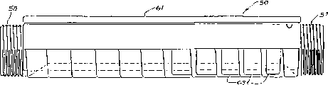
图5是气体流量计外壳的正视图:Figure 5 is a front view of the gas flowmeter housing:
图6是气体流量计外壳的后视图;Figure 6 is a rear view of the gas flowmeter housing;
图7是气体流量计外壳的测视图;Fig. 7 is a measurement view of the gas flowmeter housing;
图8是沿图5中Ⅷ-Ⅷ线所取的气体流量计的剖面图;Figure 8 is a sectional view of the gas flowmeter taken along the line VIII-VIII in Figure 5;
图9是沿图5中Ⅸ-Ⅸ线所取的气体流量计的剖面图;Fig. 9 is a sectional view of the gas flowmeter taken along line IX-IX in Fig. 5;
图10A-10D表示对应于增益设定过程的波形图。10A-10D show waveform diagrams corresponding to the gain setting process.
本最佳实施例是在图5中看到的民用气体流量计,使用一个3.5伏D型锂电池51(图8)供电,使用寿命大约8年。The preferred embodiment is the residential gas flow meter seen in FIG. 5, powered by a 3.5 volt D-cell lithium battery 51 (FIG. 8) with a service life of about 8 years.
流量计50通过测定在管52中的超声波脉冲群在两个方向上传输时间直接测定气流的速度,该管流过气体,如图6所示,其直径和长度是已知的。超声波传感器5和6分别配置在管52每端的2个气动外壳53和54内(参阅图6内部剖视图)并且,其功能即可作为超声波发射器,也可作为接收器。管52其内径为14.0毫米,并且,经过各自的带螺纹连接部分57和58的突出部分55和56接入到标准的25毫米(1英寸)瓦斯管中(未示出)。在该最佳实施例中,传感器5和6的间隔距离为175毫米。The
可用于该最佳实施例的合适的传感器类型公开在国际专利申请PCT/AU91/00157中。A suitable sensor type which may be used in the preferred embodiment is disclosed in International Patent Application PCT/AU91/00157.
在流动条件下气体体积流量,像在已有技术所熟知的那样,通过测量气体速度和管52的尺寸能很容易地计算出来。为了达到预期的精度,按顺序发送一些超声波脉冲群或信号包,靠近在测量管的接收器端的前一个脉冲群到达,每一个新的脉冲群开始被触发。平均传输时间然后被确定是利用对作为一个整体的脉冲群序列进行计时并用所发射的脉冲群数相除而实现的。单一的超声波脉冲群的产生、发射和检测今后将称之为一个“环式循环”(ringaround)。气体流量的单次扫描检测由两组预定数量的环式循环组成,首先在一个方向上,然后在另一个方向上。在各次扫描之间的间隔要选择,以便在各次测量读数之间的整个期间内都达到所需精度。对民用表计,适当的中间扫描间隔一般为16秒。The gas volume flow rate under flow conditions can be easily calculated by measuring the gas velocity and the
表计50装有一电子组件,其产生、检测超声波脉冲群并对超声波脉冲群计时。这里所述最佳实施例建立在两个应用特殊集成电路的大规模集成电路LSI基础上,一个模拟装置2和一个数字装置1。这两个装置1和2的功能可以容于一个LSI装置中,在现有技术中是热知的,这将减少电子组件的单位成本。
图1表示电子组件的整体方框图,数字装置1经过一些控制线10控制模拟装置2及两个超声波传感器5和6,一个液晶显示器(LCD)7和一个光学接口3。传感器5和6实际上配置在图6所示的气体传输管52中。一个EEPROM4(电子可擦编程存储器)为表计50提标定信息,一个簧片开关8在LCD7上方附加到防护盖59上(参阅图5),以便当盖59打开时,接通LCD7。FIG. 1 shows a general block diagram of the electronic assembly, a digital device 1 controlling an analog device 2 and two ultrasonic sensors 5 and 6 , a liquid crystal display (LCD) 7 and an optical interface 3 via some control lines 10 . The sensors 5 and 6 are actually arranged in the
在数字装置1和模拟装置2之间的一些连线9允许从数字装置1向传感器5和6发射电脉冲,并且还允许所接收的信号通向模拟装置2。连线11从模拟装置2向数字装置1传输被放大的接收信号。连线12向数字装置1传输用于增益控制和计时控制的反馈信号。在模拟装置2上产生的参考电压利用连线13传输到数字装置1。光学接口3包括一个在防护板59下方的窗口60(图5中以内剖图表示),并包括一个针(PIN)式二极管和一个发光二极管(未表示,是公知技术),以便经过一个红外串联元件,允许从外部装置接收和向外部装置发送信号。并联连接的线14将数字装置1和LCD7相连。Some connections 9 between the digital device 1 and the analog device 2 allow the transmission of electrical pulses from the digital device 1 to the sensors 5 and 6 and also allow the received signals to pass to the analog device 2 . The connection 11 transmits the amplified received signal from the analog device 2 to the digital device 1 . The
如图2所示,数字装置1包括一个逻辑运算单元(ALU)15,其经过地址和数据总线42与只读存储器(ROM)16、一个随机存取存储器(RAM)17和一排外围寄存器19相连。最好ROM16容量为4096字节,同时RAM17由两个各容纳128字节的寄存器所组成。外围寄存器19允许ALU15和数字装置1上的各特定功能元件相连,并和能够接到数字装置1的其它装置相连。As shown in Figure 2, the digital device 1 includes a logical operation unit (ALU) 15, which communicates with a read-only memory (ROM) 16, a random access memory (RAM) 17 and a bank of peripheral registers 19 via an address and data bus 42 connected. Preferably ROM16 has a capacity of 4096 bytes, while RAM17 consists of two registers each holding 128 bytes. The peripheral registers 19 allow the
时钟单元18将9.8304兆赫的时钟频率信号提供给高速计数器23,还将2.4576兆赫的CPU时钟信号提供给ALU15和用于通讯目的其它辅助多路系统。此外,时钟单元18提供32.768千赫信号用作实时时钟信号。使高速计数器23与反馈线12相连,以允许当其存储信息达到适当值时使计数器中止,然后经过外围寄存器19转入到ALU15。控制单元22向模拟装置2提供控制信号,以便在扫描过程中控制模拟装置2的运行。
信号发生器21在两对信号线9其中一对上输出超声波信号。信号发生器21的振荡频率由两个电阻和一个电容(未表示)组成的外部定时元件来设定。发生器21设计成使第一个脉冲的宽度与后面的脉冲宽度相同。信号发生器21的工作类似于本领域技术人员熟知的555定时器。通信单元20提供两个通信通道,第一个通道与EEPROM4串行连接,第二个通道通过光学接口3向外部通信装置提供串行RS232格式的连系信号。The
参阅图3,模拟装置2具有一个前置放大器24,该放大器经过其中一对连线9从传感器5或6获取所接收信号,并向一个自动增益控制(AGC)放大器25提供放大信号。用于AGC放大器的控制电压取自外部电容器40。滤波放大器26驱动一个全波精密整流器27,一RC网络28对所得信号进行滤波,并且取出整流信号的包络信号的上升部分的形状特征。滤波放大器26的输出还通过连线11送到数字装置1,并在该处转换成一系列数字脉冲。包络信号然后送到比较器29,并在该处和多个电压其中之一进行比较,该电压取决于来自内部控制单元30的控制线43的接法。比较器29提供反馈信号经过线12送到数字装置1。Referring to FIG. 3 , the analog device 2 has a preamplifier 24 which takes the received signal from the sensor 5 or 6 via a pair of wires 9 and provides an amplified signal to an automatic gain control (AGC)
偏置单元31利用带隙(band-gap)回路以便在线13上产生一与电池电压无关的,一般为1.20伏的参考电压VREF。其它所有固定参考电压都可由该电压派生,其中包括1.80伏的正的参考电压(VPR)和0.60伏的负参考电压(VNR),该电压加到一个参考母线44上。正参考电压VPR加到外部串联电阻35/36/37/38上,向比较器29输出三个参考电压。控制单元30对由数字装置1提供、经过线10传输的控制信息进行译码,并选择其中一个参考电压在比较器29中和来自滤波器28的包络信号进行比较。偏置单元31还为在模拟装置2上的所有电路模块产生一些偏置电压,这是在来自控制单元30的信号的控制之下进行的,另外还包括一个开机(power up)回路,其只有当由数字装置1提供指示才工作。此外,偏置单元31还产生一个电池监视电压(VBM),在母线44上输出。The
在模拟装置2中装有一个数模转换器(DAC),用于为AGC放大器件25提供控制电压。DAC还利用双斜率变换方法进行模数变换。模数转换进行只有通过模拟装置和数字装置1、2两种部件的综合才能进行,如下所述。A digital-to-analog converter (DAC) is provided in the analog device 2 for supplying the
数字装置1利用计数器23和控制单元22,经过控制单元30输出控制线43来控制数模转换。模拟装置2上进行数模转换的线路组成部分为一个可开关控制输入量的缓冲放大器33、一个运算放大器34,其和用于调整积分器特性的外电阻39、外部电容40连接用作积分器、以及一个比较器29。比较器29的输出用作控制总线43上的数字信号。可用开关控制的放大器33由来自控制单元22的控制线进行控制。The digital device 1 utilizes the counter 23 and the
模数转换根据两个电压源VBM、一个电源电压标度的形式和缓冲放大器32的输出能够进行。缓冲放大器32的输入连接到位于表计50内部的一个热敏电阻上(未表示)。该热敏电阻位于气动外壳53、54其中之一,用以测量流体的温度。或者,附加热敏电阻在外壳50中,以便能够监测能够影响电池51寿命的内部温度。热敏电阻一般为线性变化电阻(未表示),常用并联方式。模数转换根据VPR和VREF之间的电压进行。热敏电阻的最佳连接使VREF对应于+60°温度,VPR对应于-20°。由数字装置1的输出端向热敏电阻提供电流。仅当进行温度测量时才提供该电流。Analog-to-digital conversion is enabled from two voltage sources V BM , in the form of a supply voltage scale and the output of buffer amplifier 32 . The input of buffer amplifier 32 is connected to a thermistor (not shown) internal to
下面介绍图1、2、3所示电路的工作,用于实现这种工作方式的控制程序存储在ROM16中。The following introduces the work of the circuit shown in Figures 1, 2, and 3, and the control program for realizing this working mode is stored in the ROM16.
扫描过程由如下步骤组成:The scanning process consists of the following steps:
1.选择第一发射方向,出于确定在接收传感器处的响应电平的目的,一可变数量的单个环式循环需要进行。按这种方式连续进行试验,在试验中,调节接收器24的增益,直到接收响应水平下降落在对应某一电压值的该限值之内,该电压位于在电阻35和36、以及电阻36和37之间的连接节点处的电压值之间。该试验最多进行9次。1. Selecting the first transmission direction, a variable number of individual loop cycles need to be performed for the purpose of determining the response level at the receiving sensor. In this manner the test is continued, in which the gain of the receiver 24 is adjusted until the received response level falls within the limits corresponding to a voltage value located between
2.高速计时器23的起动与测量环式循环的本序列的开始同时,该序列可以包含任意数量的环式循环,但最好是64个。2. The high-speed timer 23 is started simultaneously with the start of the present sequence of measurement loops, which sequence may contain any number of loops, but preferably 64 loops.
3.在测量环式循环序列结束时,高速计时器23的计数器中的数值被传输到数字装置1中的外围寄存器19。3. At the end of the measuring loop sequence, the value in the counter of the high-speed timer 23 is transferred to the peripheral register 19 in the digital device 1 .
4.选择第二发射方向,重复进行步骤1、2、3中的项目。4. Select the second launch direction, and repeat steps 1, 2, and 3.
5.然后,数字装置1中的软件利用存储在外围寄存器19中的高速计时器的数值来计算该扫描周期的流量。5. Then, the software in the digital device 1 uses the value of the high-speed timer stored in the peripheral register 19 to calculate the flow rate of the scan cycle.
图4中的时间标记图表示三个环式循环的开始部分。第一个是一个正极性的环式循环,维持高输出,以便准备用于第二个环式循环的极性变换或反相。第二个,反极性脉冲群后使输出降低,最后的脉冲群为正极性。在最佳实施例中,一个以上与图中最后一个脉冲群相同的脉冲群还要被发射,而且该序列最好连续15次提供64个环式循环。图中所示信号概括如下:The time-stamped diagram in Figure 4 shows the beginnings of three circular cycles. The first is a positive polarity ring cycle, maintaining high output ready for polarity reversal or inversion of the second ring cycle. The second one, the output is lowered after the reverse polarity pulse group, and the last pulse group is positive polarity. In the preferred embodiment, more than one burst identical to the last burst in the figure is transmitted, and the sequence is preferably 15 consecutive to provide 64 loop cycles. The signals shown in the figure can be summarized as follows:
OE-振荡器起动信号。启动发射振荡器OSC。OE - Oscillator start signal. Starts the transmit oscillator OSC.
OSC-发射振荡器信号。该信号是占空度为50%的选通方波,在最佳实施例中频率为115千赫。40到200千赫的频率一般都适宜。OSC - Transmits an oscillator signal. The signal is a gated square wave with a 50% duty cycle and a frequency of 115 kHz in the preferred embodiment. A frequency of 40 to 200 kHz is generally suitable.
OG-振荡器选通门信号。由OE的上升前沿起动并且由根据OSC上升沿而工作的脉冲计数器而中止。脉冲计数器比较一个储存在外围寄存器19中的计数器限值(例如3)。计数限值由软件设定。OG - Oscillator gate signal. Started by the rising edge of OE and stopped by the pulse counter operating on the rising edge of OSC. The pulse counter compares to a counter limit (eg 3) stored in peripheral register 19 . The count limit is set by software.
OSG-门控发射振荡器信号。该信号为利用极性转换电路进行变换前的基本脉冲群信号,是由OSC和OG进行逻辑“与”得到的。OSG - Gated launch oscillator signal. This signal is the basic pulse group signal before being converted by the polarity conversion circuit, and is obtained by logic "AND" of OSC and OG.
POL-极性信号。软件可写入一个专用的外围寄存器19,表明在现行的式循环之后需要进行被发射的脉冲群的极性变换。在此之后,OG的下降沿使POL被维持。假如POL已经被维持,OG的下降沿就使其改变(negate)。POL - polarity signal. Software can write to a dedicated peripheral register 19 to indicate that a polarity inversion of the transmitted burst is required after the current formula cycle. After that, the falling edge of OG causes POL to be asserted. If POL has been asserted, the falling edge of OG negates it.
B-脉冲群(Burst)信号。其为加到发射传感器上的信号。由POL与OSG的逻辑“异或”运算得到。B-burst signal. It is the signal applied to the transmit sensor. Obtained by the logical "exclusive OR" operation of POL and OSG.
RB-接收脉冲群信号。该信号由接收传感器获得并加到接收前置放大器24。该信号滤波后(由图3的线22可得到)送到数字装置1中的一个比较器。RB - receive burst signal. This signal is obtained by the receiving sensor and applied to the receiving preamplifier 24 . This signal is filtered (available on
RCVP-接收极性信号。POL的高到低的跃变使得RCVP被维持。其由POL的F一个下降沿所改变。在该发射极性之后,一个环式循环POL改变,接收器极性就发生变化。该信号提供过0检测器47的极性控制,该极性控制由一比较器来完成,其在线11加在外围寄存器19的一个输入端,用于驱动在数字装置上的控制单元22。RCVP - Receive polarity signal. A high-to-low transition of POL causes RCVP to be maintained. It is changed by a falling edge of F on POL. After the transmit polarity, one loop cycle POL changes, the receiver polarity changes. This signal provides polarity control through the zero detector 47, which is accomplished by a comparator applied on line 11 to an input of the peripheral register 19 for driving the
BRR-整流的接收脉冲群信号。其为精密整流器27的输出。BRR - rectified receive burst signal. It is the output of the precision rectifier 27 .
ENV-包络信号。该信号对BRR进行滤波而获得,由于滤波过程时间常数的影响,该信号相对滞后于BRR。水平虚线表示相应于电阻37和38连接节点处电压的检测阈值。包络信号被加到比较器29上。ENV - Envelope signal. The signal is obtained by filtering the BRR, and due to the influence of the time constant of the filtering process, the signal lags behind the BRR relatively. The horizontal dashed line represents the detection threshold corresponding to the voltage at the junction of resistors 37 and 38 . The envelope signal is applied to a comparator 29 .
FB-反馈信号。当ENV通过检测阈值时,使FB产生由低到高的跃变。由RCVP所确定极性的接收脉冲群信号RB的下一个信号跃变利用触发信号OE不同时地启动一个环式循环。FB - feedback signal. When ENV passes the detection threshold, make FB produce a transition from low to high. The next signal transition of the receive burst signal RB with a polarity determined by RCVP asynchronously initiates a loop cycle with the trigger signal OE.
信号发生器21包括用于产生OE、OSC、OG、OSG、POL和B信号的回路。
图4中所示信号每一个所示都在相邻脉冲群之间被间断。这是因为,一个脉冲群的发射是在最接近的前一个脉冲群接收的基础上进行的,并且因为,脉冲群传越两个传感器5和6之间距离所需时间明显大于产生脉冲群所用时间。当在典型自然气体中,超声波脉冲群传输速度大约为430米/秒(声音在空气中的速度大约340米/秒),传输时间一般大约0.41毫秒。然而,发射脉冲群所用时间一般大约4倍于其脉冲周期,如发射频率为105千赫,发射时间约30微秒。这里所引传输时间对声音而言是在静止空气中传输,该传输时间在本最佳实施例中将依流体流动速度而变化。假如该流体是一种液体,由于声音在液体中的速度较高,该传输时间将明显缩短。例如,盐水中声音的速度一般为每秒1200米到1600米之间,这取决于水中的含盐量和水温。The signals shown in Figure 4 are each shown interrupted between adjacent bursts. This is because the emission of a burst is based on the reception of the closest preceding burst, and because the time required for a burst to travel across the distance between the two sensors 5 and 6 is significantly greater than the time required to generate the burst time. When in a typical natural gas, the transmission speed of the ultrasonic burst is about 430 m/s (the speed of sound in air is about 340 m/s), and the transmission time is generally about 0.41 milliseconds. However, the time used to transmit a burst of pulses is generally about 4 times its pulse period, for example, the transmission frequency is 105 kHz, and the transmission time is about 30 microseconds. The transit times quoted here are for sound in still air, which in the preferred embodiment will vary with the velocity of the fluid flow. If the fluid is a liquid, the transit time will be significantly shorter due to the higher speed of sound in the liquid. For example, the speed of sound in salt water is typically between 1200 and 1600 meters per second, depending on the salinity and temperature of the water.
在图4中,在波形B和RB之间的箭头表示所接收脉冲群基本上对准下一脉冲群的发射。In FIG. 4, the arrows between waveforms B and RB indicate that a received burst is substantially aligned with the transmission of the next burst.
以上概述的步骤下面将详细介绍。首先,需要进行增益设定步骤,以确保超声波脉冲群检测回路正确工作。工作频率在80到150千赫之间,更典型是105-125千赫的信号发生器21产生1到10个脉冲,典型为3个脉冲的脉冲群,该脉冲群被放大并被送到发射传感器。该脉冲群的波形表示为图4中的波形B。当该信号到达接收前置放大器24的输出端时,由于传感器5和6限定的频率响应,该信号已经变成带有平滑包络线基本上为正弦的系列波,如图4波形RB所示。因为任传感器中存在谐振和在电声信号通道中的滤波效应,该包络线幅度迅速增加,然后,在若干个周期内逐渐衰减。The steps outlined above are described in detail below. First, a gain setting step is required to ensure proper operation of the ultrasonic burst detection loop. A
在接收检测器前置放大器24输出端的信号幅值基本上做为气体流动速度、温度和相对于气流的发射方向的函数而变化。此外,接收信号的幅度能够增加是利用改变发射传感器的驱动方式,从单端驱动变为双端驱动。对单端驱动而言,仅一侧传感器被驱动,而对双端驱动而言,传感器的一端用正常信号驱动而另外一侧利用正常信号的逻辑互补信号来驱动。一般,所接收信号的幅度并不是基于任何一次扫描,那么就必须进行一定数量的单个环式循环试验发射,以确定所需接收器增益和发射器驱动方式,使得在前置放大器的输出端获得恒定的幅度。The signal amplitude at the output of receive detector preamplifier 24 varies substantially as a function of gas flow velocity, temperature and emission direction relative to the gas flow. In addition, the amplitude of the received signal can be increased by changing the driving method of the transmitting sensor from single-ended driving to double-ended driving. With single-ended drive, only one side of the sensor is driven, while with double-ended drive, one end of the sensor is driven with the normal signal and the other side is driven with the logical complement of the normal signal. Typically, the magnitude of the received signal is not based on any one sweep, and a certain number of single loop test transmissions must be made to determine the required receiver gain and transmitter drive in such a way that the output of the preamplifier is obtained constant amplitude.
本过程由数字装置1中的软件来控制。计时器41连接到一个适宜的时钟信号上,并且电容器40经过电阻39充电,以监视从0到255的时钟周期的数量。电容器40上的电压加到电压控制的AGC放大器25上This process is controlled by software in the digital device 1 . Timer 41 is connected to a suitable clock signal and capacitor 40 is charged via
一组脉冲群通过该装置被发射,经过接收、整流和滤波的色络信号的上升段在比较器29中和三个参考电压进行比较。第一个是最低的电压,是由电阻37和38之间所得到的参考电压ETH,该电压一般用于启动过零检测。下一个电压ELL对所接收的包络信号的峰值来说是可容许的最低幅值,由电阻36和37之间的节点可得到,最后一个参考电压EHL是容许的最高的包络信号幅值,从电阻35和36之间节点可得到。A group of pulse trains is transmitted through the device, and the rising segment of the received, rectified and filtered chromatic signal is compared with three reference voltages in comparator 29 . The first is the lowest voltage, which is the reference voltage ETH obtained between resistors 37 and 38, which is generally used to enable zero-crossing detection. The next voltage ELL is the lowest allowable amplitude for the peak value of the received envelope signal, obtained from the junction between
AGC控制电压是通过对DAC的电容器40充电而产生的,用于监视从0到255的时钟周期的数量。充电电流由电阻39控制。电容40上的电压加到电压控制的AGC放大器25上,并且,在接收脉冲期间得以保持。The AGC control voltage is generated by charging the capacitor 40 of the DAC and is used to monitor the number of clock cycles from 0 to 255. The charging current is controlled by
在图10A-10D上利用波形FB所表示的反馈线12加到数字装置1初始为逻辑零,并当越过每一个参考电压时,状态随之改变。当反馈线12经历0-1-0的变化(图10C)时,在滤波器28(波形ENV)的输出端所接收的信号处于令人满意的水平,稳态逻辑零表示接收信号电平太低(图10A),而跃变序列0-1表示信号峰值虽在测量参考电平之上,但仍然太低(图10B)。跃变序列0-1-0-1表示接收信号的包络线已经越过所有3个参考电平因而太高(图10D)。这些信息借助于外围寄存器19中的一个寄存器中的两个二进制数码进行处理适用于软件,并且该软件利用二进制的交换(chop)的、逐步试验的算法,以限制其区间在电容40可能充电次数从0到255的范围内,会聚在于获得满意的增益。假如,最终增益明显小于可能最大值的50%,并且假定对发射传感器同时要采用双端驱动方式,就可能采用单端驱动方式来节约电源。在这种情况下,再一次借助单端驱动、软件完成整个增益设定程序。相反,所接收幅度不能上升到单端驱动所需满意的电平以及255个时钟周期的电容充电时间,用双端驱动重复增益设定程序。满意的驱动方式和增益一经确立,ROM软件就存储这些结果,以确保测量环式循环的序列,并且还将作为下一次扫描的起始点。
仍然参照图4,在图左测的波形B包括4个上升的脉冲。相应地,所接收的脉冲群RB将随上升的脉冲起始,从波形B的第一个上升沿到波形RB的第一个上升沿之间的持续时间为超声波信号的传输时间。如图4所示,包络信号ENV和所接收的脉冲群RB的上升的包络信号一起开始上升。高增益、低品质因数(Q)的传感器5和6的使用可保证包络信号快速增加,使得如前所述可以进行检测。因此,在包络信号的上升部分的阈值检测一贯是可预知的,并且,所接收的脉冲群RB的下一次过零用于触发下一脉冲群的发射,最终用于停止计数器23或重新发射。相应地,从图4可以看出,由计数器23所记数值对应于传输时间加上在该发射频率下的两次半振荡,用该环式循环数量相乘再加上由电子电路所引起的延迟。一个对应于两次半振荡的常数乘以环式循环的数目加上电子电路的延迟可以表示在ROM4中。该常数当计算传输时间时,由计数器23中所测量的时间就可推断。Still referring to FIG. 4, waveform B on the left side of the figure includes 4 rising pulses. Correspondingly, the received pulse group RB will start with a rising pulse, and the duration from the first rising edge of waveform B to the first rising edge of waveform RB is the transmission time of the ultrasonic signal. As shown in FIG. 4, the envelope signal ENV starts to rise together with the rising envelope signal of the received burst RB. The use of high gain, low quality factor (Q) sensors 5 and 6 ensures a rapid increase in the envelope signal, allowing detection as previously described. Thus, the threshold detection at the rising part of the envelope signal is always predictable, and the next zero crossing of the received burst RB is used to trigger the transmission of the next burst, eventually to stop the counter 23 or to retransmit. Correspondingly, it can be seen from FIG. 4 that the value counted by the counter 23 corresponds to the transmission time plus two and a half oscillations at the transmission frequency, multiplied by the number of ring cycles plus the Delay. A constant corresponding to two half oscillations multiplied by the number of ring cycles plus the delay of the electronic circuit can be represented in ROM 4. This constant can be deduced from the time measured in the counter 23 when calculating the transmission time.
在一般情况下,对任何一个环式循环,电子电路的延迟是不明显的。当传输时间为0.5毫秒数量级时,电子电路延迟一般数量级为毫微秒。In general, electronic circuit delays are not noticeable for any one loop cycle. When the transmission time is on the order of 0.5 milliseconds, the delay of electronic circuits is generally on the order of nanoseconds.
脉冲群到达精确计时的中心问题是选择一个点,该点能够经常被鉴别而不考虑脉冲群包络信号和它构成的正弦波之间的相对移动。本文所述最佳方法是在所接收的波形序列的早期部分要选择一个特定的过零点,对应于脉冲被激励时而不是谐振时,并利用该过零点做为计时标志。在波形的被驱动部分进行检测是最佳的,因为该部分的频率和相位为所发射的波形锁定。波形的后来部分由于谐振影响可能不能精确反映原有超声波脉冲群的频率。A central problem in the precise timing of burst arrival is choosing a point that can often be identified regardless of the relative movement between the burst envelope signal and the sine wave it constitutes. The best approach described here is to choose a specific zero-crossing early in the received waveform sequence, corresponding to when the pulse is excited rather than resonant, and use that zero-crossing as a timing marker. Detection is optimal on the driven portion of the waveform because that portion is frequency and phase locked to the transmitted waveform. Subsequent portions of the waveform may not accurately reflect the frequency of the original ultrasound burst due to resonance effects.
为了完成该检测,所接收信号在单元27进行整流(波形BRR),在单元28进行滤波,以再现如图4波形ENV所示的包络信号波形。经过滤波后的包络信号的上升部分在比较器29和一参考电压相比较,该电压取自电阻37和38之间的节点处。当包络信号ENV达到参考电压时,数字装置1中的过零检测器47经过一限定时间(至少为所选择的超声波频率下的一个周期并不大于两个周期)被起动,在线11上未经滤波的接收信号的一个数字化的派生量的下一次跃变,相应于RB的下一次过零被用作计时参考点以记录脉冲群的到达。为了获得有用的结果,参考电压必须是由滤波器28输出的接收包络信号最大幅度的固定比例部分,如在图4波形ENV以虚线所表示的。To accomplish this detection, the received signal is rectified (waveform BRR) at unit 27 and filtered at unit 28 to reproduce the envelope signal waveform as shown in FIG. 4 as waveform ENV. The rising portion of the filtered envelope signal is compared in comparator 29 with a reference voltage taken at the node between resistors 37 and 38 . When the envelope signal ENV reaches the reference voltage, the zero-crossing detector 47 in the digital device 1 is activated after a limited time (at least one cycle under the selected ultrasonic frequency is not more than two cycles), and there is no signal on the line 11. The next transition of a digitized derivative of the filtered received signal, corresponding to the next zero crossing of the RB, is used as a timing reference point to register the arrival of the burst. In order to obtain useful results, the reference voltage must be a fixed proportional portion of the maximum amplitude of the receive envelope signal output by filter 28, as indicated by the dashed line in waveform ENV of FIG.
现在转到环式循环序列的起始部分,ROM软件启动在达到所需环式循环的数值时将终止的一个计数器,然后使环式循环序列起动是通过在外围计数器组19中的一个控制寄存器写入代码,该代码从该寄存器送到控制单元22。该起动代码的写入还启动运行频率为9.3804兆赫的高速计数器23。最后,ROM16软件执行等待(WATT)指令。控制单元22启动事件过程的顺序很大程度上是自动进行的。按照这种方式,在接收传感器(5或6)处到达的超声波脉冲群的特定过零检测立即引起再发射。在线11上的RB的下一个信号跃变具有适当的极性,非同时地触发再发射。反馈信号12使ALU15从等待状态“唤醒”(awaken)。在ALU15“唤醒”时,ROM软件修改其环式循环序列计数并检查限值是否已经达到。假如环式循环序列计数已经达到一个小于其予定限值的计数值,软件消除原先写入控制单元22的起动代码,因此断开再发射回路并在下一个环式循环之后终止该序列。软件然后使引起“唤醒”的标志位复位,另一个等待指令执行。该软件工作总是在超声波信号沿管52传输的期间发生,与检测和再发射的自动处理无关。Turning now to the initial portion of the looping sequence, the ROM software starts a counter which will terminate when the desired looping value is reached, and then causes the looping sequence to start via a control register in the peripheral counter bank 19 A code is written, which is sent to the
在第三个步骤中,在高速计数器23寄存的24位数值由ROM软件读出并放入RAM17以备将来计算流量之用。In the third step, the 24-bit value registered in the high-speed counter 23 is read out by the ROM software and put into the RAM 17 for future flow calculation.
最后,软件要进行两次多位的除法,把高速计时器已经校正电子电路延迟的数值划入表计的标定系数,在测试后和使用前预先编程进入表计。如前所述,大部分电子电路延迟起因于超声波脉冲群前沿的到达不能被检测。更确切地说是,深入脉冲群的几个固定数目的周期(2)的过零才被检测。此外在传感器5、6和检测回路中的其它元件中都存在相位滞后。对应于电子电路延迟的计时器计数数值,对任何特定的表计来说是固定的和已知的,并且存储在EEPROM4中。在多位除法结果之间的差值和中间扫描时间一起被用来计算该扫描周期的流量。该流量然后加到一个积算气体寄存器,用来显示和自动读出。Finally, the software needs to perform two multi-digit divisions, and divide the value of the high-speed timer that has corrected the delay of the electronic circuit into the calibration coefficient of the meter, which is pre-programmed into the meter after testing and before use. As mentioned earlier, most electronic circuit delays arise from the fact that the arrival of the leading edge of the ultrasonic burst cannot be detected. More precisely, zero crossings are detected a few fixed number of periods (2) deep into the burst. Furthermore, there is a phase lag both in the sensors 5, 6 and in the other elements in the detection circuit. The timer count value corresponding to the delay of the electronic circuit is fixed and known for any particular meter and is stored in EEPROM4. The difference between the multi-bit division results is used together with the intermediate scan time to calculate the flow rate for that scan period. This flow is then added to an integrated gas register for display and automatic readout.
气体消耗量可以在两个寄存器的其中一个进行积算,这取决于每天使用时间,假如需要可以进行正常报表。Gas consumption can be totaled in one of two registers, depending on the time of day used, and normal reporting can be done if required.
气体温度利用热敏电阻测量,该热敏电阻(未示出)安装在气动外壳(53或54)其中一个之上并接到运算放大器32的一个输入端,由软件对在扫描期间获取的流量值进行温度修正。The gas temperature is measured using a thermistor (not shown) mounted on one of the pneumatic housings (53 or 54) and connected to an input of the operational amplifier 32, and the flow rate acquired during the sweep is analyzed by software. The value is corrected for temperature.
因为本最佳实施例基本上用于民用,使用长寿命锂电池,电能的节约就是十分重要的,所采取的一些步骤都是为减少能量消耗。Because this preferred embodiment is basically used for civilian use, using long-life lithium batteries, the saving of electric energy is very important, and some steps taken are all for reducing energy consumption.
首先,用于高速计时器的9.3804兆赫时钟信号是利用数字方法由时钟单元18中的4.9152兆赫的振荡器产生。高速振荡器的大功率需求因此被减少了。之所以节约能量是因为确定基本振荡频率的晶体在时钟电路中消耗占功率的主要部分,并且由于使晶体工作在“半”速,可以节约能量75%。First, the 9.3804 MHz clock signal for the high speed timer is digitally generated from the 4.9152 MHz oscillator in the
其次,仅当防护盖59被抬起,簧片开关8接通,液晶显示7才起动,而且软件确保在盖59被支撑打开的过程中仅在有限的时间内维持起动状态。Secondly, the
第三,在通信单元20中的外部通信回路正常以每500毫秒中取1毫秒定时询问的方式工作,并且只有当接收有效通信输入信号时才完全起动。Third, the external communication loop in the communication unit 20 normally operates with a timed interrogation of 1 millisecond out of every 500 milliseconds, and is only fully activated when a valid communication input signal is received.
第四,采用例如在国际专利申请PCT/AU91/00157中所公开的低品质因数Q的传感器5和6保证了以低驱动功率产生超声波信号。Fourth, the use of sensors 5 and 6 with a low quality factor Q such as disclosed in International Patent Application PCT/AU91/00157 ensures that ultrasonic signals are generated with low drive power.
还有,存储对最后一次扫描所取增益值的技术保证在大多数情况下用于确定所需增益的二进制交换法并没有被采用,而仅仅是在扫描之初为了确认增益是否适当需要进行单个检查环式循环。Also, the technique of storing the gain value taken for the last scan ensures that in most cases the binary swap method used to determine the required gain is not used, but only a single Check the loop.
最后,ALU15和与之相关的部件在大部分时间内处于低功率的停机状态,而且只有利用来自外部通信单元的中断信号或利用来自实时时钟的中断信号,在需要扫描时才“唤醒”(woken)工作。Finally, the
参照图5-9,表计50有一个最好由压铸锌或铝制成的外壳61,虽然其它金属或塑料也可采用。管52和外壳61一起形成一个整体,如图8和9所示。盖62用一些固定螺钉63固定在外壳61之上,如图6所示。聚氯丁橡胶密封件71装在外壳61和盖62之间。电池室盖64用固定螺钉65固定在外壳61上,参阅图5和图9。Referring to Figures 5-9, the
图1、2、3中的电子部件装在一印刷电路板(PCB)66上,参阅图9,并且图8中导线67从电池51接到印刷电路板PCB66上,导线68从PCB66接到位于管52中的传感器5和6上。The electronic parts among Fig. 1,2,3 are contained on a printed circuit board (PCB) 66, refer to Fig. 9, and
外壳61还具有一个大的散热片69,它和外壳形成一个整体,帮助扩散表计50发出的热量。The housing 61 also has a large heat sink 69 integrally formed with the housing to help dissipate the heat emitted by the
由于表计50试图用于世界范围内各种气候条件下,存在由于过热损坏电池51引起表计工作失效的可能性,在外壳61内保证适度的温升是很重要的。Since the
利用一种白色防止再涂复类型的油漆涂刷外壳也是有助于控制温度的,这就保证用户不能将外壳61涂成他们自己选择的颜色,防止影响表计50的散热。Painting the housing with a white anti-repainting type of paint is also helpful in temperature control, which ensures that users cannot paint the housing 61 in a color of their choice to prevent heat dissipation from being affected by the
参阅图5、7和8,围绕外壳61可设置一个遮阳盖70,以增强排除阳光的直接幅射。盖板71应当开有多孔,以便允许空气围绕散热片69循环流通,并且可由用户油漆以改进外观。Referring to Figures 5, 7 and 8, a
参阅图4,该最佳实施例使用的脉冲群或超声波信号包,其所具有的极性或相位与相邻的信号包相反。在图4中,第1个和第3个脉冲群由正向跃变起始,反过来,第2个脉冲群由负向跃变起始。或者相反,第1和第3个脉冲群可由负向跃变起始。这种配置具体地公开在由本申请的同一申请人同时提出的申请号为PK6894的澳大利亚专利申请中,题为“流体流量测量中的波模抑制”,可结合其公开文本相互参考,这种配置用来明显减少高次声波在管52中的传播,这些高次声波影响由接收传感器进行超声波信号包的接收的检测,带来误差。最有效的方法是,每隔2个具有相同起始相位的信号包有一个反相的超声波信号包被发射。误差的产生是由于超声波信号包的多路传输所引起,由传感器5和6发射的超声波的传播因管52壁的反射形成多路传播。因为高次声波传播速度明显小于基波或一次波,对基波需要进行检测,因为它是一次波,检测声速度变化这在流体流量中是很重要的。Referring to Figure 4, the preferred embodiment uses bursts or packets of ultrasound signals that have opposite polarity or phase to adjacent packets. In Figure 4, the 1st and 3rd bursts start with a positive-going transition, and conversely, the 2nd burst starts with a negative-going transition. Or conversely, the 1st and 3rd bursts can be initiated by negative going transitions. This arrangement is specifically disclosed in Australian Patent Application No. PK6894, entitled "Mode Suppression in Fluid Flow Measurement", filed concurrently by the same applicant as the present application, cross-referenced in conjunction with its disclosure, this arrangement It is used to significantly reduce the propagation of high-order sound waves in the
该最佳实施例对12.5毫米管,在正常精度为0.1-0.15%的情况下,在0-7立方米/每小时的范围内能够实现线性测量,并且对75%的最大流量范围,精度优于±2%。The preferred embodiment is capable of linear measurement in the range of 0-7 cubic meters per hour with a normal accuracy of 0.1-0.15% for 12.5mm tubes and excellent accuracy for 75% of the maximum flow range within ±2%.
以上所述仅为本发明和各种改型中的一个实施例,很明显在现有技术所熟知那些技术也能在本发明实施,并没有脱离本发明的保护范围。The above description is only one embodiment of the present invention and its various modifications. Obviously, those technologies well known in the prior art can also be implemented in the present invention without departing from the protection scope of the present invention.
例如,光学接口能够易于为射频装置或磁感应装置所取代。For example, the optical interface can be easily replaced by a radio frequency device or a magnetic induction device.
还有,对于工业标准或需要监视传输应用场合,与使用电池工作相反,也可提供市电供电。Also, for industry standards or applications requiring monitored transmissions, mains power is also available as opposed to battery operation.
再者,对大的电源线路,可以在该线路内装置全部表计。Furthermore, for large power lines, all meters can be installed in the line.
此外,传感器不需要用管子或管道安装。例如,假如传感器被安装在船壳外部,表计将用作检测船经过水的相对速度。而当船是静止的,表计将测量水流速度。这样,流速加到船的实际速度。热敏电阻能够用来测量海水温度并相应考虑补偿水中的声速。这还可能取决于合盐量并且一个独立的含盐量测量装置(未表示)也可用来补偿水中的声速。In addition, the sensor does not need to be installed with pipes or pipes. For example, if the sensor is mounted on the outside of the hull, the gauge will be used to detect the relative speed of the boat through the water. And when the boat is stationary, the meter will measure the speed of the water. In this way, the velocity of the flow adds to the actual velocity of the boat. Thermistors can be used to measure seawater temperature and compensate for the speed of sound in the water accordingly. This may also depend on the salt content and a separate salinity measurement device (not shown) may also be used to compensate for the sound velocity in the water.
还有,数字装置1的过零检测器47通过改变发射脉冲序列的极性能使其输出误差降低,即假如对一个环式循环第一个发射信号是正的,然后下一个环式循环序列的第一个发射信号则是负的。In addition, the zero-crossing detector 47 of the digital device 1 can reduce its output error by changing the polarity of the transmitted pulse sequence, that is, if the first transmitted signal of a circular cycle is positive, then the first signal of the next circular cycle sequence will be positive. A transmit signal is then negative.
本发明可应用于流体流量测量,特别是气体。The invention is applicable to fluid flow measurement, especially gas.
Claims (33)
Applications Claiming Priority (2)
| Application Number | Priority Date | Filing Date | Title |
|---|---|---|---|
| AUPK6893 | 1991-06-25 | ||
| AUPK689391 | 1991-06-25 |
Publications (2)
| Publication Number | Publication Date |
|---|---|
| CN1070473A CN1070473A (en) | 1993-03-31 |
| CN1046026C true CN1046026C (en) | 1999-10-27 |
Family
ID=3775502
Family Applications (1)
| Application Number | Title | Priority Date | Filing Date |
|---|---|---|---|
| CN92108885A Expired - Fee Related CN1046026C (en) | 1991-06-25 | 1992-06-25 | Electronic fluid flow meter |
Country Status (20)
| Country | Link |
|---|---|
| US (1) | US5553505A (en) |
| EP (1) | EP0591349B1 (en) |
| JP (1) | JPH07500662A (en) |
| CN (1) | CN1046026C (en) |
| AT (1) | ATE163756T1 (en) |
| AU (1) | AU666122B2 (en) |
| CA (1) | CA2112094A1 (en) |
| DE (1) | DE69224643T2 (en) |
| DK (1) | DK0591349T3 (en) |
| ES (1) | ES2112907T3 (en) |
| FI (1) | FI935822A7 (en) |
| GR (1) | GR3026606T3 (en) |
| HU (1) | HUT68387A (en) |
| IE (1) | IE80654B1 (en) |
| IN (1) | IN178275B (en) |
| NZ (1) | NZ243293A (en) |
| PL (1) | PL169741B1 (en) |
| SG (1) | SG45209A1 (en) |
| TW (1) | TW246714B (en) |
| WO (1) | WO1993000569A1 (en) |
Families Citing this family (56)
| Publication number | Priority date | Publication date | Assignee | Title |
|---|---|---|---|---|
| EP0690974A4 (en) * | 1993-03-09 | 1996-05-22 | Commw Scient Ind Res Org | Fluid meter construction |
| AU682498B2 (en) * | 1993-03-09 | 1997-10-09 | AGL Consultancy Pty. Limited | Fluid meter construction |
| ES2066723B1 (en) * | 1993-05-25 | 1995-11-01 | Contadores De Agua De Zaragoza | IMPROVEMENTS FOR FLUID METERS. |
| GB2282447B (en) * | 1993-09-29 | 1997-02-12 | Siemens Measurements Ltd | Improvements in or relating to gas meters |
| FR2734361B1 (en) | 1995-05-17 | 1997-07-18 | Schlumberger Ind Sa | DEVICE FOR MEASURING THE FLOW SPEED OF A FLUID BY ULTRASOUND |
| DE19522697A1 (en) * | 1995-06-22 | 1997-01-09 | Sick Optik Elektronik Erwin | Method and circuit arrangement for measuring the flow velocity by means of acoustic transit time differences |
| AUPN606095A0 (en) * | 1995-10-19 | 1995-11-09 | AGL Consultancy Pty. Limited | Digital speed determination in ultrasonic flow measurements |
| LT4240B (en) | 1995-12-15 | 1997-11-25 | Skanska Teknik Ab | Heat insulating outer wall for a building |
| US5753824A (en) * | 1996-06-12 | 1998-05-19 | Welch Allyn, Inc. | Sampling method and apparatus for use with ultrasonic flowmeters |
| US5777238A (en) * | 1996-06-12 | 1998-07-07 | Welch Allyn, Inc. | Driver-receiver apparatus for use with ultrasonic flowmeters |
| US5748504A (en) * | 1996-06-12 | 1998-05-05 | Welch Allyn, Inc. | Calibration method for use with ultrasonic flowmeters |
| US5710379A (en) * | 1996-10-04 | 1998-01-20 | Dieterich Technology Holding Corp. | Apparatus and method for determining a flow count |
| IT1286007B1 (en) * | 1996-11-28 | 1998-06-26 | Sgs Thomson Microelectronics | FLOW METER OF A FLUID |
| AUPP318098A0 (en) * | 1998-04-24 | 1998-05-21 | Commonwealth Scientific And Industrial Research Organisation | A liquid flow meter |
| SE9802762D0 (en) * | 1998-08-19 | 1998-08-19 | Siemens Elema Ab | Zero crossing detector and method of determining a zero crossing point |
| FR2785048B1 (en) * | 1998-10-22 | 2000-12-08 | Air Liquide | DEVICE FOR MEASURING A USER'S FLUID CONSUMPTION OVER A GIVEN DURATION |
| US6158288A (en) * | 1999-01-28 | 2000-12-12 | Dolphin Technology, Inc. | Ultrasonic system for measuring flow rate, fluid velocity, and pipe diameter based upon time periods |
| AUPQ061399A0 (en) | 1999-05-27 | 1999-06-17 | University Of Sydney, The | Acoustic flow meters |
| DE19948892C2 (en) * | 1999-10-11 | 2002-07-18 | Asm Automation Sensorik Messte | Pulse detector and method for the detection of sinusoidal pulses |
| AUPQ480199A0 (en) | 1999-12-22 | 2000-02-03 | AGL Consultancy Pty. Limited | Timed window ultrasonic gas meter with nose cone |
| US6595071B1 (en) | 2000-01-06 | 2003-07-22 | Transoma Medical, Inc. | Estimation of error angle in ultrasound flow measurement |
| US6435037B1 (en) | 2000-01-06 | 2002-08-20 | Data Sciences International, Inc. | Multiplexed phase detector |
| US6539316B1 (en) | 2000-01-06 | 2003-03-25 | Data Sciences International, Inc. | Phase detector |
| SE517922C2 (en) * | 2000-11-15 | 2002-08-06 | Aake Stroemberg | Method and apparatus for determining the velocity of a fluid |
| US6757623B2 (en) * | 2001-04-20 | 2004-06-29 | Ads Corporation | Flow transport analysis method and system |
| JP4886120B2 (en) * | 2001-05-16 | 2012-02-29 | 東京計器株式会社 | Ultrasonic current meter |
| DE10254054A1 (en) * | 2002-11-19 | 2004-06-03 | Endress + Hauser Flowtec Ag, Reinach | Device for determining and / or monitoring the volume and / or mass flow of a medium |
| TW557973U (en) * | 2003-01-17 | 2003-10-11 | Yan-Tang Lin | Connecting joint structure for water pipe |
| JP4394918B2 (en) * | 2003-10-03 | 2010-01-06 | 淳一 櫛引 | High-accuracy ultrasonic material characteristic analyzer and temperature control method thereof |
| US7152490B1 (en) | 2005-08-15 | 2006-12-26 | Daniel Measurement And Control, Inc. | Methods for determining transducer delay time and transducer separation in ultrasonic flow meters |
| TR200604281U (en) * | 2006-08-10 | 2006-11-21 | Elektromed Elektroni̇k Sanayi̇ Ve Sağlik Hi̇zmetleri̇li̇mi̇ted Şi̇rketi̇ | Ultrasonic Water Meter |
| US7911306B2 (en) * | 2008-01-08 | 2011-03-22 | Daniel Measurement And Control, Inc. | Transformer board |
| DE102008019989B4 (en) * | 2008-04-21 | 2010-07-01 | Mib Gmbh Messtechnik Und Industrieberatung | Ultrasonic measuring arrangement |
| DE102008019992B4 (en) * | 2008-04-21 | 2010-07-01 | Mib Gmbh Messtechnik Und Industrieberatung | Ultrasonic measuring arrangement |
| CN101901596B (en) * | 2010-08-18 | 2012-09-19 | 王伟东 | Touch type horn system with counting function |
| WO2012129101A1 (en) | 2011-03-18 | 2012-09-27 | Soneter, LLC | Methods and apparatus for fluid flow measurement |
| CN102297712B (en) * | 2011-07-12 | 2012-09-05 | 北京理工大学 | Method for measuring propagation time of ultrasonic echo |
| RU2491518C1 (en) * | 2012-02-27 | 2013-08-27 | Общество с ограниченной ответственностью Инженерный центр "Энергопрогресс" | Meter of level and interface of two products |
| US8833384B2 (en) | 2012-08-06 | 2014-09-16 | Schneider Electric Buildings, Llc | Advanced valve actuation system with integral freeze protection |
| US9534795B2 (en) | 2012-10-05 | 2017-01-03 | Schneider Electric Buildings, Llc | Advanced valve actuator with remote location flow reset |
| US10295080B2 (en) | 2012-12-11 | 2019-05-21 | Schneider Electric Buildings, Llc | Fast attachment open end direct mount damper and valve actuator |
| WO2014143922A1 (en) | 2013-03-15 | 2014-09-18 | Schneider Electric Buildings, Llc | Advanced valve actuator with true flow feedback |
| EP2971901B1 (en) | 2013-03-15 | 2018-10-17 | Schneider Electric Buildings LLC | Advanced valve actuator with integral energy metering |
| TWI500908B (en) * | 2013-06-19 | 2015-09-21 | Ind Tech Res Inst | Ultrasonic flow meter and ultrasonic flow measuring |
| DK178244B1 (en) * | 2013-06-21 | 2015-09-28 | Agena As | A system or a method for measuring flow in a flow duct |
| US10176709B2 (en) * | 2015-04-30 | 2019-01-08 | Honeywell International Inc. | Optical gas meter disconnect |
| CA2895361C (en) * | 2015-06-19 | 2023-08-01 | Accutron Instruments Inc. | Method and system for ultrasonic airflow measurements |
| US11473949B2 (en) | 2017-12-03 | 2022-10-18 | Eugene Fourie | Flowmeter |
| DE102018006628A1 (en) * | 2018-08-22 | 2020-02-27 | Diehl Metering Gmbh | measuring device |
| CN109638858B (en) * | 2018-11-30 | 2021-10-15 | 中国能源建设集团广东省电力设计研究院有限公司 | Frequency modulation peak modulation method, device and system |
| CN110207771B (en) * | 2019-06-14 | 2020-08-04 | 浙江启尔机电技术有限公司 | Single-channel continuous multi-ultrasonic-signal synchronous timing circuit and timing method thereof |
| WO2020259781A1 (en) * | 2019-06-25 | 2020-12-30 | Kamstrup A/S | Ultrasonic flow meter and a method of determining a flow rate |
| EP4081763A1 (en) | 2019-12-23 | 2022-11-02 | Belimo Holding AG | System and method for measuring a flow of gas through a channel |
| CN113504389A (en) * | 2021-07-27 | 2021-10-15 | 美卓伦仪表(常州)有限公司 | Circuit and method for measuring ultrasonic wave propagation time |
| CN114659573A (en) * | 2022-03-21 | 2022-06-24 | 浙江威星智能仪表股份有限公司 | Double-end sound wave excitation system and method of transducer, electronic device and storage medium |
| JP2024101224A (en) * | 2023-01-17 | 2024-07-29 | 富士電機株式会社 | Peak hold circuit and ultrasonic flow meter |
Citations (6)
| Publication number | Priority date | Publication date | Assignee | Title |
|---|---|---|---|---|
| US3282101A (en) * | 1963-02-27 | 1966-11-01 | Tokyo Keiki Seizosho Company L | Ultrasonic flow speed measuring apparatus |
| US3678731A (en) * | 1968-10-04 | 1972-07-25 | Catherine Margaret Davey | Apparatus for measuring the flow velocity of fluids |
| US4480485A (en) * | 1982-10-01 | 1984-11-06 | Panametrics, Inc. | Acoustic flowmeter with envelope midpoint tracking |
| US4515021A (en) * | 1983-07-29 | 1985-05-07 | Panametrics, Inc. | Intervalometer time measurement apparatus and method |
| US4603589A (en) * | 1983-12-27 | 1986-08-05 | Kabushiki Kaisha Toshiba | Ultrasonic flowmeter |
| US4885942A (en) * | 1986-09-30 | 1989-12-12 | Siemens Aktiengesellschaft | Ultrasound flow rate meter using a phase difference method and apparatus |
Family Cites Families (10)
| Publication number | Priority date | Publication date | Assignee | Title |
|---|---|---|---|---|
| DE452531C (en) * | 1926-01-10 | 1927-11-12 | Franz Gerdes | Automatic gripper for single loads |
| US4022058A (en) * | 1975-08-07 | 1977-05-10 | Brown Alvin E | Apparatus for determining the arrival time of alternating signals |
| JPS57190281A (en) * | 1981-05-19 | 1982-11-22 | Yokogawa Hokushin Electric Corp | Ultrasonic wave measuring apparatus |
| NL182662C (en) | 1981-10-13 | 1990-04-17 | Sawgrain Limited | FRAME WITH CLAMP BODIES. |
| US4538469A (en) * | 1983-07-29 | 1985-09-03 | Panametrics, Inc. | Integrated threshold arming method and apparatus |
| NL8403221A (en) * | 1984-10-23 | 1986-05-16 | Nedap Nv | ULTRASONIC FLOW METER WITH WIDE RANGE. |
| SE456279B (en) * | 1986-09-16 | 1988-09-19 | Bost & Co Ab | SET AND DEVICE FOR TIMING AN Acoustic Pulse |
| AU600679B2 (en) * | 1986-09-16 | 1990-08-23 | Saab Marine Electronics Aktiebolag | A method of indicating the time of an acoustic pulse and a device therefor |
| GB2237639B (en) * | 1989-10-31 | 1994-07-06 | British Gas Plc | Measurement system |
| EP0452531B1 (en) * | 1990-04-20 | 1995-01-04 | Siemens Aktiengesellschaft | Electric measuring device for determining the propagation time of an electrical signal |
-
1992
- 1992-06-24 NZ NZ243293A patent/NZ243293A/en unknown
- 1992-06-25 SG SG1996001309A patent/SG45209A1/en unknown
- 1992-06-25 JP JP5501201A patent/JPH07500662A/en active Pending
- 1992-06-25 EP EP92913600A patent/EP0591349B1/en not_active Expired - Lifetime
- 1992-06-25 AU AU21727/92A patent/AU666122B2/en not_active Ceased
- 1992-06-25 CA CA002112094A patent/CA2112094A1/en not_active Abandoned
- 1992-06-25 DK DK92913600T patent/DK0591349T3/en active
- 1992-06-25 WO PCT/AU1992/000314 patent/WO1993000569A1/en not_active Ceased
- 1992-06-25 DE DE69224643T patent/DE69224643T2/en not_active Expired - Fee Related
- 1992-06-25 PL PL92301878A patent/PL169741B1/en not_active IP Right Cessation
- 1992-06-25 US US08/175,361 patent/US5553505A/en not_active Expired - Fee Related
- 1992-06-25 ES ES92913600T patent/ES2112907T3/en not_active Expired - Lifetime
- 1992-06-25 IN IN456CA1992 patent/IN178275B/en unknown
- 1992-06-25 CN CN92108885A patent/CN1046026C/en not_active Expired - Fee Related
- 1992-06-25 AT AT92913600T patent/ATE163756T1/en not_active IP Right Cessation
- 1992-06-25 HU HU9303695A patent/HUT68387A/en unknown
- 1992-07-01 IE IE922038A patent/IE80654B1/en not_active IP Right Cessation
- 1992-07-01 TW TW081105215A patent/TW246714B/zh active
-
1993
- 1993-12-23 FI FI935822A patent/FI935822A7/en not_active Application Discontinuation
-
1998
- 1998-04-10 GR GR980400802T patent/GR3026606T3/en unknown
Patent Citations (6)
| Publication number | Priority date | Publication date | Assignee | Title |
|---|---|---|---|---|
| US3282101A (en) * | 1963-02-27 | 1966-11-01 | Tokyo Keiki Seizosho Company L | Ultrasonic flow speed measuring apparatus |
| US3678731A (en) * | 1968-10-04 | 1972-07-25 | Catherine Margaret Davey | Apparatus for measuring the flow velocity of fluids |
| US4480485A (en) * | 1982-10-01 | 1984-11-06 | Panametrics, Inc. | Acoustic flowmeter with envelope midpoint tracking |
| US4515021A (en) * | 1983-07-29 | 1985-05-07 | Panametrics, Inc. | Intervalometer time measurement apparatus and method |
| US4603589A (en) * | 1983-12-27 | 1986-08-05 | Kabushiki Kaisha Toshiba | Ultrasonic flowmeter |
| US4885942A (en) * | 1986-09-30 | 1989-12-12 | Siemens Aktiengesellschaft | Ultrasound flow rate meter using a phase difference method and apparatus |
Also Published As
| Publication number | Publication date |
|---|---|
| PL169741B1 (en) | 1996-08-30 |
| DK0591349T3 (en) | 1998-09-28 |
| US5553505A (en) | 1996-09-10 |
| IE922038A1 (en) | 1992-12-30 |
| EP0591349A1 (en) | 1994-04-13 |
| IN178275B (en) | 1997-03-22 |
| WO1993000569A1 (en) | 1993-01-07 |
| FI935822A0 (en) | 1993-12-23 |
| TW246714B (en) | 1995-05-01 |
| DE69224643D1 (en) | 1998-04-09 |
| DE69224643T2 (en) | 1998-10-15 |
| EP0591349B1 (en) | 1998-03-04 |
| HU9303695D0 (en) | 1994-04-28 |
| HUT68387A (en) | 1995-06-28 |
| ES2112907T3 (en) | 1998-04-16 |
| IE80654B1 (en) | 1998-11-04 |
| CA2112094A1 (en) | 1993-01-07 |
| EP0591349A4 (en) | 1994-08-31 |
| ATE163756T1 (en) | 1998-03-15 |
| JPH07500662A (en) | 1995-01-19 |
| AU2172792A (en) | 1993-01-25 |
| NZ243293A (en) | 1995-03-28 |
| FI935822A7 (en) | 1994-02-21 |
| AU666122B2 (en) | 1996-02-01 |
| SG45209A1 (en) | 1998-01-16 |
| CN1070473A (en) | 1993-03-31 |
| GR3026606T3 (en) | 1998-07-31 |
Similar Documents
| Publication | Publication Date | Title |
|---|---|---|
| CN1046026C (en) | Electronic fluid flow meter | |
| RU2423673C2 (en) | Energy-efficient ultrasonic flow metre | |
| CN1576803A (en) | Ultrasonic gas flow meter and device for measuring exhaust gas flow of internal combustion engines and method for obtaining gas flow | |
| CN1350634A (en) | Flow rate measuring device | |
| CN112997051B (en) | Dynamic Temperature Calibration of Ultrasonic Transducers | |
| CN1055994C (en) | Method and device for monitoring changes in current value of fluid flow passing through a flowmeter | |
| US20250109976A1 (en) | Gas volume determination in fluid | |
| CN108613708A (en) | A kind of miniature intrinsic safety ultrasonic gas flowmeter | |
| CN114442078A (en) | Method for detecting flight time, ultrasonic flowmeter and optical equipment | |
| CN108917866A (en) | A kind of ultrasonic sensor and its installation method for compound pipeline complex pipeline flow detection | |
| RU2004108050A (en) | MEASURING SYSTEM WITH LOGOMETRIC FREQUENCY OUTPUT | |
| CN105738651A (en) | Ultrasonic wave wind speed measurement apparatus with temperature compensation | |
| CN1950678A (en) | Ultrasonic measuring instruments for determining and/or monitoring the volume and/or mass flow of media | |
| CN202582790U (en) | Ultrasonic heat meter | |
| JP3838209B2 (en) | Flow measuring device | |
| CN1032667C (en) | Ultrasonic tester of liquid concentration | |
| CN110261492A (en) | A kind of method and device of Serial No. driving ultrasonic sensor | |
| RU2042925C1 (en) | Turbine consumption meter | |
| Ma et al. | The research of MCU ultrasonic range finder | |
| SU1626146A1 (en) | Device for determining gas content in liquids | |
| CN114353892A (en) | Method for intelligently improving metering accuracy reduction caused by transducer aging | |
| JP3945530B2 (en) | Flow measuring device | |
| CN207301325U (en) | Test pit equipment based on ultrasonic ranging | |
| CN116202581A (en) | Ultrasonic flowmeter combining FPGA technology and high-performance algorithm | |
| JPH0815428A (en) | Ultrasonic distance sensor |
Legal Events
| Date | Code | Title | Description |
|---|---|---|---|
| C06 | Publication | ||
| PB01 | Publication | ||
| C10 | Entry into substantive examination | ||
| SE01 | Entry into force of request for substantive examination | ||
| C14 | Grant of patent or utility model | ||
| GR01 | Patent grant | ||
| C15 | Extension of patent right duration from 15 to 20 years for appl. with date before 31.12.1992 and still valid on 11.12.2001 (patent law change 1993) | ||
| OR01 | Other related matters | ||
| C19 | Lapse of patent right due to non-payment of the annual fee | ||
| CF01 | Termination of patent right due to non-payment of annual fee |