CN103891232A - Apparatus and method for UE-specific demodulation reference signal scrambling - Google Patents
Apparatus and method for UE-specific demodulation reference signal scrambling Download PDFInfo
- Publication number
- CN103891232A CN103891232A CN201280049078.1A CN201280049078A CN103891232A CN 103891232 A CN103891232 A CN 103891232A CN 201280049078 A CN201280049078 A CN 201280049078A CN 103891232 A CN103891232 A CN 103891232A
- Authority
- CN
- China
- Prior art keywords
- pucch
- scrambling
- scid
- csi
- rrc
- Prior art date
- Legal status (The legal status is an assumption and is not a legal conclusion. Google has not performed a legal analysis and makes no representation as to the accuracy of the status listed.)
- Granted
Links
Images


Classifications
-
- H—ELECTRICITY
- H04—ELECTRIC COMMUNICATION TECHNIQUE
- H04L—TRANSMISSION OF DIGITAL INFORMATION, e.g. TELEGRAPHIC COMMUNICATION
- H04L5/00—Arrangements affording multiple use of the transmission path
- H04L5/003—Arrangements for allocating sub-channels of the transmission path
- H04L5/0048—Allocation of pilot signals, i.e. of signals known to the receiver
- H04L5/0051—Allocation of pilot signals, i.e. of signals known to the receiver of dedicated pilots, i.e. pilots destined for a single user or terminal
-
- H—ELECTRICITY
- H04—ELECTRIC COMMUNICATION TECHNIQUE
- H04L—TRANSMISSION OF DIGITAL INFORMATION, e.g. TELEGRAPHIC COMMUNICATION
- H04L5/00—Arrangements affording multiple use of the transmission path
- H04L5/003—Arrangements for allocating sub-channels of the transmission path
- H04L5/0032—Distributed allocation, i.e. involving a plurality of allocating devices, each making partial allocation
- H04L5/0035—Resource allocation in a cooperative multipoint environment
-
- H—ELECTRICITY
- H04—ELECTRIC COMMUNICATION TECHNIQUE
- H04L—TRANSMISSION OF DIGITAL INFORMATION, e.g. TELEGRAPHIC COMMUNICATION
- H04L5/00—Arrangements affording multiple use of the transmission path
- H04L5/0091—Signalling for the administration of the divided path, e.g. signalling of configuration information
-
- H—ELECTRICITY
- H04—ELECTRIC COMMUNICATION TECHNIQUE
- H04W—WIRELESS COMMUNICATION NETWORKS
- H04W72/00—Local resource management
- H04W72/12—Wireless traffic scheduling
-
- H—ELECTRICITY
- H04—ELECTRIC COMMUNICATION TECHNIQUE
- H04W—WIRELESS COMMUNICATION NETWORKS
- H04W72/00—Local resource management
- H04W72/20—Control channels or signalling for resource management
- H04W72/23—Control channels or signalling for resource management in the downlink direction of a wireless link, i.e. towards a terminal
Landscapes
- Engineering & Computer Science (AREA)
- Signal Processing (AREA)
- Computer Networks & Wireless Communication (AREA)
- Mobile Radio Communication Systems (AREA)
Abstract
Description
技术领域technical field
本申请一般涉及无线通信,并且更具体地,涉及用于UE特定的解调参考信号加扰的系统和方法。The present application relates generally to wireless communications, and more particularly, to systems and methods for UE-specific demodulation reference signal scrambling.
背景技术Background technique
在3GPP长期演进(LTE)和长期演进高级(LTE-A)系统中,存在两种类型的上行链路参考信号(UL RS):解调参考信号(DM-RS)和声探参考信号(SRS)。对于物理上行链路共享信道(PUSCH)传输,DM-RS信号在两个SC-FDMA(单载波频分多址)符号(子帧中两个时隙的每个时隙一个SC-FDMA符号)上发送。SRS在一个SC-FDMA符号(子帧中的第二时隙的最后的SC-FDMA符号)上发送。在LTE标准的版本10中,DM-RS加扰初始化取决于物理小区标识(PCI)和加扰标识(SCID)。In 3GPP Long Term Evolution (LTE) and Long Term Evolution Advanced (LTE-A) systems, there are two types of Uplink Reference Signals (UL RS): Demodulation Reference Signal (DM-RS) and Sounding Reference Signal (SRS ). For Physical Uplink Shared Channel (PUSCH) transmission, the DM-RS signal is transmitted over two SC-FDMA (Single Carrier Frequency Division Multiple Access) symbols (one SC-FDMA symbol for each of the two slots in the subframe) to send. The SRS is transmitted on one SC-FDMA symbol (the last SC-FDMA symbol of the second slot in the subframe). In Release 10 of the LTE standard, DM-RS scrambling initialization depends on Physical Cell Identity (PCI) and Scrambling Identification (SCID).
发明内容Contents of the invention
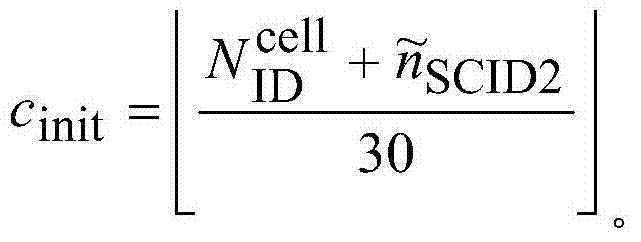
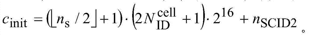
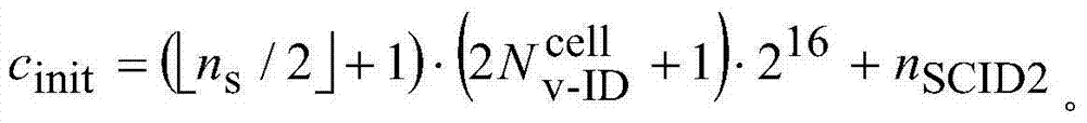
提供了用在被配置为与无线网络中的多个基站通信的用户设备(UE)中的方法。该方法包括:接收调度用于UE的物理下行链路共享信道(PDSCH)的下行链路授权,下行链路授权在物理下行链路控制信道(PDCCH)或增强物理下行链路控制信道(ePDCCH)中发送。该方法还包括接收为PDSCH的解调提供的UE特定的解调参考信号(UE-RS),其中根据使用初始化值cinit来初始化的加扰序列被加扰。下行链路授权包括一比特加扰标识符(SCID)信息字段,被配置为指示两个候选对当中的包括加扰标识符和nSCID虚拟小区ID的一对值,这对值要用于确定用于UE-RS的初始化值cinit。cinit根据等式来确定,其中ns是时序数目。A method for use in a user equipment (UE) configured to communicate with a plurality of base stations in a wireless network is provided. The method includes: receiving a downlink grant scheduled for a physical downlink shared channel (PDSCH) of a UE, the downlink grant being on a physical downlink control channel (PDCCH) or an enhanced physical downlink control channel (ePDCCH) sent in. The method also includes receiving a UE-specific demodulation reference signal (UE-RS) provided for demodulation of the PDSCH, wherein it is scrambled according to a scrambling sequence initialized using an initialization value cinit . The downlink grant includes a one-bit scrambling identifier (SCID) information field configured to indicate which of the two candidate pairs includes the scrambling identifier and n SCID virtual cell ID A pair of values, which are used to determine the initialization value c init for the UE-RS. c init according to the equation To determine, where n s is the sequence number.
提供了被配置为与无线网络中的多个基站通信的用户设备(UE)。该用户设备包括处理器,被配置为接收调度用于UE的物理下行链路共享信道(PDSCH)的下行链路授权,下行链路授权在物理下行链路控制信道(PDCCH)或增强物理下行链路控制信道(ePDCCH)中发送。处理器被进一步配置为接收为PDSCH的解调提供的UE特定的解调参考信号(UE-RS),其中根据使用初始化值cinit来初始化的加扰序列对UE-RS加扰。下行链路授权包括一比特加扰标识符(SCID)信息字段,该字段被配置为指示两个候选对当中包括加扰标识符nSCID和虚拟小区ID
提供了被配置用于与多个用户设备(UE)通信的基站。该基站包括处理器,该处理器被配置为发送调度用于UE的物理下行链路共享信道(PDSCH)的下行链路授权,下行链路授权在物理下行链路控制信道(PDCCH)或增强物理下行链路控制信道(ePDCCH)中发送。该处理器还被配置为发送为PDSCH的解调提供的UE特定的解调参考信号(UE-RS),其中根据使用初始化值cinit来初始化的加扰序列对UE-RS加扰。下行链路授权包括一比特加扰标识符(SCID)信息字段,该字段被配置为指示两个候选对当中的包括加扰标识符nSCID和虚拟小区ID

在进行下面的“本发明的具体实施方式”之前,阐述遍布这篇专利文献使用的某些词汇和短语的定义可能是有利的:术语“包括”和“包含”及其派生词意思是没有限制的包含;术语“或”是包含的,意思是和/或;短语“与……关联”和“与其关联的”及其派生短语可以意思是包括、被包括在……之内、与……互连、包含、被包含在……之内、连接到或与……连接、耦接到或与……耦接、与……可通信的、与……合作、交织、并列、与……最近、被捆绑至或与……捆绑、具有、具有……属性等等;而术语“控制器”意思是控制至少一个操作的任何设备、系统或其部分,这样的设备可以用硬件、固件或软件或者其中至少两个的一些组合来实现。应该注意到与任何特定的控制器相关的功能可以是集中的或者分布的,无论本地还是远程地。遍布这篇专利文献提供了某些词汇和短语的定义,本领域普通技术人员应该理解,在很多,如果不是大多数情况中,这些定义适用于如此定义的词汇和短语的之前的以及将来的使用。Before proceeding to the "Detailed Description of the Invention" below, it may be advantageous to set forth the definitions of certain words and phrases used throughout this patent document: The terms "comprises" and "comprises" and their derivatives mean without limitation The term "or" is inclusive, meaning and/or; the phrases "in connection with" and "in connection with" and their derivatives can mean including, included in, with... Interconnected, contained, contained within, connected to or connected with, coupled to or coupled with, communicable with, cooperating with, interwoven, juxtaposed, with recent, tied to or tied to, having, possessing the attributes of, etc.; and the term "controller" means any device, system, or part thereof that controls at least one software or some combination of at least two of them. It should be noted that the functionality associated with any particular controller may be centralized or distributed, whether locally or remotely. Definitions for certain words and phrases are provided throughout this patent document, those of ordinary skill in the art should understand that in many, if not most instances, these definitions apply to prior, as well as future uses of such defined words and phrases .
附图说明Description of drawings
为了更完全地理解本公开及其优点,现在结合附图参考下面的描述,在附图中相似的参考标号表示相似的部分:For a more complete understanding of the present disclosure and its advantages, reference is now made to the following description taken in conjunction with the accompanying drawings in which like reference numerals represent like parts:
图1图解了根据本公开的实施例的无线网络;Figure 1 illustrates a wireless network according to an embodiment of the present disclosure;
图2示出了根据此公开的实施例的无线发送路径的高级示图;Figure 2 shows a high-level diagram of a wireless transmission path according to an embodiment of this disclosure;
图3示出了根据此公开的实施例的无线接收路径的高级示图;Figure 3 shows a high-level diagram of a wireless receive path according to an embodiment of this disclosure;
图4示出了根据此公开的实施例的LTE系统中的上行链路载波中的一对物理资源块(PRB)中的物理上行链路控制信道(PUCCH)资源划分;FIG. 4 illustrates physical uplink control channel (PUCCH) resource partitioning in a pair of physical resource blocks (PRBs) in an uplink carrier in an LTE system according to an embodiment of this disclosure;
图5示出了根据此公开的实施例的用于PUCCH的调制符号的映射;Figure 5 shows the mapping of modulation symbols for PUCCH according to an embodiment of this disclosure;
图6示出根据此公开的实施例的在物理下行链路共享信道(PDSCH)区域中的扩展的物理下行链路控制信道(E-PDCCH)的安置;Figure 6 illustrates placement of an extended physical downlink control channel (E-PDCCH) in a physical downlink shared channel (PDSCH) region according to an embodiment of this disclosure;
图7示出根据此公开的实施例的协作多点场景,其中将一个物理小区ID分配给宏小区和许多射频拉远头(remote radio head,RRH);Figure 7 shows a CoMP scenario according to an embodiment of this disclosure, where one physical cell ID is assigned to a macro cell and many remote radio heads (RRHs);
图8示出根据此公开的实施例的具有小区特定的和传输点(TP)特定的序列的混合的上行链路参数信号(RS)基本序列生成;Figure 8 illustrates hybrid uplink parameter signal (RS) basic sequence generation with cell-specific and transmission point (TP)-specific sequences according to an embodiment of this disclosure;
图9示出根据此公开的实施例的指定用于PUCCH序列间干扰减少的PUCCH PRB;Figure 9 shows PUCCH PRBs designated for PUCCH inter-sequence interference reduction according to an embodiment of this disclosure;
图10示出根据此公开的实施例的异构网络中的下行链路传输;Figure 10 illustrates downlink transmissions in a heterogeneous network according to an embodiment of this disclosure;
图11示出根据此公开的实施例的用于UE-RS加扰的动态指示的从DCI格式2B延长的第一下行链路控制信息(DCI)格式;以及Figure 11 illustrates a first downlink control information (DCI) format extended from DCI format 2B for dynamic indication of UE-RS scrambling according to an embodiment of this disclosure; and
图12示出根据此公开的实施例的用于UE-RS加扰的动态指示的从DCI格式2B延长的第二DCI格式。Figure 12 shows a second DCI format extended from DCI format 2B for dynamic indication of UE-RS scrambling according to an embodiment of this disclosure.
具体实施方式Detailed ways
下面讨论的图1至图12以及在此专利文献中用来描述本公开的原理的各种实施例仅是作为说明,而不应该以任何方式被解释为限制本公开的范围。本领域技术人员将理解可以在任何适当布置的无线通信系统中实施本公开的原理。1 through 12 , discussed below, and the various embodiments used to describe the principles of the disclosure in this patent document are by way of illustration only and should not be construed in any way to limit the scope of the disclosure. Those skilled in the art will understand that the principles of the present disclosure may be implemented in any suitably arranged wireless communication system.
由此将下面的文献和标准描述合并到本公开中,就像在此完全阐述一样:(i)3GPP技术规范No.36.211,版本10.1.0,“E-UTRA,Physical Channels andModulation(物理信道和调制)”(下文中“REF1”);(ii)3GPP技术规范No.36.212,版本10.1.0,“E-UTRA,Multiplexing and Channel Coding(复用和信道编码)”(下文中“REF2”);以及(iii)3GPP技术规范No.36.213,版本10.1.0,“E-UTRA,Physical Layer Procedures(物理层过程)”(下文中“REF3”)。The following literature and standard descriptions are hereby incorporated into this disclosure as if fully set forth herein: (i) 3GPP Technical Specification No. 36.211, Version 10.1.0, "E-UTRA, Physical Channels and Modulation (Physical Channels and Modulation) Modulation)" (hereinafter "REF1"); (ii) 3GPP Technical Specification No.36.212, Version 10.1.0, "E-UTRA, Multiplexing and Channel Coding (multiplexing and channel coding)" (hereinafter "REF2") and (iii) 3GPP Technical Specification No. 36.213, Version 10.1.0, "E-UTRA, Physical Layer Procedures" (hereinafter "REF3").
图1示出根据本公开一个实施例的无线网络100。图1中示出的无线网络100的实施例仅用于说明。在不脱离此公开的范围的情况下,可以使用无线网络100的其他实施例。Figure 1 illustrates a
无线网络100包括eNodeB(eNB)101、eNB102和eNB103。eNB101与eNB102和eNB103通信。eNB101也与因特网协议(IP)网络130通信,诸如因特网、私有IP网络或其他数据网络。
取决于网络类型,可以代替“eNodeB”使用其他公知术语,诸如“基站”或“接入点”。为了方便,在此会使用术语“eNodeB”来指代向远程终端提供无线接入的网络基础结构组件。Depending on the network type, other well-known terms such as "base station" or "access point" may be used instead of "eNodeB". For convenience, the term "eNodeB" will be used herein to refer to a network infrastructure component that provides wireless access to remote terminals.
eNB102向eNB102的覆盖区域120之内的第一多个用户设备(UE)提供到网络130的无线宽带接入。第一多个UE包括UE111,其可以位于小型企业中;UE112,其可以位于企业中;UE113,其可以位于WiFi热点中;UE114,其可以位于第一住宅中;UE115,其可以位于第二住宅中;以及UE116,其可以是移动设备,诸如蜂窝电话机、无线膝上型计算机、无线PDA等等。UE111-116可以是任何无线通信设备,诸如,但不限于,移动电话机、移动PDA和任何移动站(MS)。The eNB 102 provides wireless broadband access to a
为了方便,在此使用术语“用户设备”或“UE”来指定无线地接入eNB的任何远程无线设备,无论该UE是移动设备(例如,蜂窝电话机)还是通常地被认为是固定设备(例如,台式个人计算机、自动贩卖机等)。在其他系统中,可以使用其他公知术语来代替“用户设备”,诸如“移动站”(MS)、“用户站”(SS)、“远程终端”(RT)、“无线终端”(WT)等等。For convenience, the term "user equipment" or "UE" is used herein to designate any remote wireless device that accesses an eNB wirelessly, whether the UE is a mobile device (e.g., a cell phone) or is generally considered a fixed device ( For example, desktop personal computers, vending machines, etc.). In other systems, other well-known terms may be used instead of "user equipment", such as "mobile station" (MS), "subscriber station" (SS), "remote terminal" (RT), "wireless terminal" (WT), etc. wait.
eNB103向eNB103的覆盖区域之内的第二多个UE提供无线宽带接入。第二多个UE包括UE115和UE116。在一些实施例中,使用LTE或LTE-A技术,eNB101-103可以彼此通信并与UE111-116通信。The eNB 103 provides wireless broadband access to a second plurality of UEs within the coverage area of the eNB 103 . The second plurality of UEs includes UE115 and UE116. In some embodiments, eNBs 101-103 may communicate with each other and with UEs 111-116 using LTE or LTE-A technology.
虚线显示了覆盖区域120和125的近似范围,仅仅为了图解和说明的目的将其近似示为圆形。应该清楚地理解,取决于基站的配置和与自然和人造障碍物相关的无线环境的变化,与基站相关的覆盖区域,例如,覆盖区域120和125可以具有其他形状,包括不规则的形状。Dashed lines show the approximate extent of
虽然图1描绘了无线网络100的一个示例,但是可以对图1进行各种改变。例如,另一种类型的数据网络,诸如有线网络,可以替换无线网络100。在有线网络中,网络终端可以代替eNB101-103和UE111-116。有线连接可以代替图1中描绘的无线连接。Although FIG. 1 depicts one example of a
图2是无线发送路径的高级示图。图3是无线接收路径的高级示图。在图2和图3中,发送路径200可以例如在图1的eNB102中实施,并且接收路径300可以例如在诸如图1的UE116的UE中实施。然而,将理解,接收路径300可以在eNB(例如图1的eNB102)中实施,并且发送路径200可以在UE中实施。Figure 2 is a high-level diagram of a wireless transmission path. Figure 3 is a high-level diagram of a wireless receive path. In FIGS. 2 and 3 , transmit
发送路径200包括信道编码和调制块205、串到并(S到P)块210、尺寸N快速傅立叶逆变换(IFFT)块215、并到串(P到S)块220、添加循环前缀块225、上变频器(UC)230。接收路径300包括下变频器(DC)255、移除循环前缀块260、串到并(S到P)块265、尺寸N快速傅立叶变换(FFT)块270、并到串(P到S)块275、信道解码和解调块280。The transmit
图2和图3中至少一些组件可以用软件实施,而其他组件可以通过可配置的硬件(例如,处理器)或者软件和可配置的硬件的混合来实施。特别是,注意到在此公开文献中描述的FFT块和IFFT块可以被实施为可配置的软件算法,其中可以根据实施来修改尺寸N的值。At least some of the components in FIGS. 2 and 3 may be implemented in software, while other components may be implemented in configurable hardware (eg, a processor) or a mixture of software and configurable hardware. In particular, note that the FFT blocks and IFFT blocks described in this publication can be implemented as configurable software algorithms, where the value of size N can be modified depending on the implementation.
此外,虽然此公开针对的是实施快速傅立叶变换和快速傅立叶逆变换的实施例,但是这仅仅作为说明而不应该认为是限制本公开的范围。应该理解,在本公开的替换实施例中,可以分别用离散傅立叶变换(DFT)函数和离散傅立叶逆变换(IDFT)函数来容易地代替快速傅立叶变换函数和快速傅立叶逆变换函数。应该理解,对于DFT和IDFT函数,N变量的值可以是任何整数(例如,1、2、3、4等),而对于FFT和IFFT函数,N变量的值可以是2的乘方的任何整数(例如,1、2、4、8、16等)。Additionally, while this disclosure is directed to embodiments implementing Fast Fourier Transforms and Inverse Fast Fourier Transforms, this is by way of illustration only and should not be considered limiting of the scope of the disclosure. It should be understood that in alternative embodiments of the present disclosure, the Fast Fourier Transform function and the Inverse Fast Fourier Transform function may be easily replaced by a Discrete Fourier Transform (DFT) function and an Inverse Discrete Fourier Transform (IDFT) function, respectively. It should be understood that for the DFT and IDFT functions, the value of the N variable can be any integer (e.g., 1, 2, 3, 4, etc.), while for the FFT and IFFT functions, the value of the N variable can be any integer power of 2 (eg, 1, 2, 4, 8, 16, etc.).
在发送路径200中,信道编码和调制块205接收一组信息比特,向输入的比特施加编码(例如,LDPC编码)和调制(例如,四相相移键控(QPSK)或正交幅度调制(QAM))来产生频域调制符号的序列。串到并块210将串行调制的符号转换(例如,解复用)为并行数据来产生N个并行符号流,其中N是在eNB102和UE116中使用的IFFT/FFT尺寸。尺寸N IFFT块215然后在N个并行符号流上执行IFFT操作来产生时域输出信号。并到串块220转换(即,复用)来自尺寸N IFFT块215的并行时域输出符号来产生串行时域信号。添加循环前缀块225然后向时域信号插入循环前缀。最后,上变频器230将添加循环前缀块225的输出调制(即,上变频)到RF频率用于经由无线信道传输。在转换到RF频率之前,信号还可以在基带被滤波。In transmit
发送的RF信号在通过无线信道之后到达UE116,并且与在eNB102的操作相反的操作被执行。下变频器255将接收的信号下变频到基带频率,并且移除循环前缀块260移除循环前缀来产生串行时域基带信号。串到并块265将时域基带信号转换为并行时域信号。尺寸N FFT块270然后执行FFT算法来产生N个并行的频域信号。并到串块275将并行频域信号转换为调制的数据符号的序列。信道解码和解调块280解调并且然后解码调制的符号来恢复初始的输入数据流。The transmitted RF signal reaches UE 116 after passing through the wireless channel, and an operation opposite to that at
eNB101-103的每个可以实施类似于在下行链路中向UE111-116发送的发送路径,并且可以实施类似于在上行链路中从UE111-116接收的接收路径。类似地,UE111-116的每个可以实施与用于在上行链路中向eNB101-103发送的结构对应的发送路径,并且可以实施与用于在下行链路中从eNB101-103接收的结构对应的接收路径。Each of the eNBs 101-103 may implement a transmit path similar to transmitting in the downlink to the UEs 111-116, and may implement a receive path similar to receiving in the uplink from the UEs 111-116. Similarly, each of UEs 111-116 may implement a transmit path corresponding to a structure for transmitting in the uplink to eNB 101-103, and may implement a structure corresponding to a structure for receiving in downlink from eNB 101-103 receiving path.
在LTE和LTE-A系统中,存在两种类型的上行链路参考信号(UL RS):解调参考信号(DM-RS)和声探参考信号(SRS)。对于物理上行链路共享信道(PUSCH)传输,DM-RS信号在两个SC-FDMA(单载波频分多址)符号(子帧中两个时隙的每个时隙一个SC-FDMA符号)上发送。SRS在一个SC-FDMA符号(子帧中的第二时隙的最后的SC-FDMA符号)上发送。In LTE and LTE-A systems, there are two types of uplink reference signal (UL RS): demodulation reference signal (DM-RS) and sounding reference signal (SRS). For Physical Uplink Shared Channel (PUSCH) transmission, the DM-RS signal is transmitted over two SC-FDMA (Single Carrier Frequency Division Multiple Access) symbols (one SC-FDMA symbol for each of the two slots in the subframe) to send. The SRS is transmitted on one SC-FDMA symbol (the last SC-FDMA symbol of the second slot in the subframe).
为了生成UL RS序列,用户站首先生成作为CAZAC(等幅零自相关)序列的基本UL RS序列。然后用户站对基本UL RS序列施加循环移位(CS),其中CS∈{0,1,...,11}。根据LTE版本10(“Rel-10”)规范,基本UL RS序列是小区特定的序列,即,是物理小区ID的函数。To generate the UL RS sequence, the subscriber station first generates the basic UL RS sequence which is a CAZAC (Constant Amplitude Zero Autocorrelation) sequence. The subscriber station then applies a cyclic shift (CS) to the base UL RS sequence, where CS ∈ {0,1,...,11}. According to the LTE Release 10 ("Rel-10") specification, the basic UL RS sequence is a cell-specific sequence, ie, a function of the physical cell ID.
CS和基本UL RS序列被分配给用户站以便维持小的用户间干扰,或者使得用户站的UL RS序列正交或准正交。当使用不同的CS从相同的基本UL RS序列生成多个UL RS序列时,它们是正交的。当相同小区中的多个用户站在相同的UL BW中复用时(即,小区内干扰),用户间干扰功率电平相对较高。为了减轻在这种情况中的用户间干扰的影响,基站可以将UL RS序列正交化。即,基站可以给那些用户站分配不同的CS。CS and basic UL RS sequences are allocated to subscriber stations in order to maintain small inter-user interference, or to make the UL RS sequences of subscriber stations orthogonal or quasi-orthogonal. When multiple UL RS sequences are generated from the same basic UL RS sequence using different CSs, they are orthogonal. When multiple user stations in the same cell are multiplexed in the same UL BW (i.e., intra-cell interference), the inter-user interference power level is relatively high. To mitigate the effects of inter-user interference in this case, the base station can orthogonalize the UL RS sequences. That is, the base station may assign different CSs to those subscriber stations.
如果从不同的UL RS序列生成多个UL RS序列,则不管它们的CS是否不同,它们都是准正交的(即,具有相对小的互相关性)。当在不同小区中的多个用户站在相同的UL BW中复用时(即,小区内干扰),用户间干扰功率电平相对较低。然而,为了确保干扰不与期望的信号相干累加,向那些用户站分配不同的基本序列。If multiple UL RS sequences are generated from different UL RS sequences, they are quasi-orthogonal (i.e., have relatively small cross-correlation) regardless of whether their CSs are different. When multiple user stations in different cells are multiplexed in the same UL BW (i.e., intra-cell interference), the inter-user interference power level is relatively low. However, to ensure that interference does not coherently accumulate with the desired signal, different base sequences are assigned to those subscriber stations.
在LTE中存在30个基本UL RS序列组,其中每组通过u=0,1,...,29来索引。在组内,当RS序列长度大于或等于6个RB(或84(=12x7)个子载波)时,存在由v=0,1索引的两个基本序列。当RS序列长度少于6个RB时,仅存在一个基本序列。In LTE there are 30 basic UL RS sequence groups, where each group is indexed by u=0,1,...,29. Within a group, when the RS sequence length is greater than or equal to 6 RBs (or 84 (=12x7) subcarriers), there are two basic sequences indexed by v=0,1. When the RS sequence length is less than 6 RBs, there is only one basic sequence.
基本UL RS序列是CAZAC序列,但是取决于序列的长度而不同地生成。对于用于1或2个RB(或者12或24个子载波)的基本序列,基本RS序列是计算机生成的CAZAC序列。对于用于多于2个RB(或多于24个子载波)的基本序列,基本RS序列是Zadoff-Chu(ZC)序列。在REF1中,在5.5.1.1节中如下描述ZC序列生成,其中PRB中的子载波数目是

对于
其中第q根Zadoff-Chu序列被定义为where the qth root Zadoff-Chu sequence is defined as
q由下面提供q is provided by

Zadoff-Chu序列的长度由使得
为了进一步减少小区间干扰(例如,R1-080241),LTE定义序列组跳频(SGH)。当(通过小区特定的RRC(无线资源控制)参数Group-hopping-enabled)启动SGH时,UL RS的基本序列组索引(u)随着时隙改变。存在17个跳频和30个序列移位图案(504(>510)个图案用于小区规划)。在REF1中,分别在5.5.1.3节和5.5.1.4节中说明SGH和序列跳频(SH),其内容合并在下。To further reduce inter-cell interference (eg, R1-080241), LTE defines Sequence Group Hopping (SGH). When SGH is enabled (by the cell-specific RRC (Radio Resource Control) parameter Group-hopping-enabled), the basic sequence group index (u) of the UL RS changes with the slot. There are 17 frequency hopping and 30 sequence shifting patterns (504 (>510) patterns for cell planning). In REF1, SGH and Sequence Hopping (SH) are described in Sections 5.5.1.3 and 5.5.1.4, respectively, the contents of which are incorporated below.
5.5.1.3组跳频5.5.1.3 Group frequency hopping
时隙ns中的序列组数目u由组跳频图案fgh(ns)和序列移位图案fss定义,根据是The number of sequence groups u in a slot n s is defined by the group hopping pattern f gh (n s ) and the sequence shift pattern f ss according to
u=(fgh(ns)+fss)mod30u=(f gh (n s )+f ss )mod30
存在17个不同的跳频图案和30个不同的序列移位图案。可以利用由更高层提供的小区特定的参数Group-hopping-enabled来启动或禁用序列组跳频。尽管在小区基础上被启动,也可以通过更高层参数Disable-sequence-group-hopping来对某一UE禁用用于PUSCH的序列组跳频。PUCCH和PUSCH具有相同的跳频图案但是可以具有不同的序列移位图案。There are 17 different frequency hopping patterns and 30 different sequence shifting patterns. Sequence group hopping can be enabled or disabled with the cell-specific parameter Group-hopping-enabled provided by higher layers. Although enabled on a cell basis, sequence group hopping for PUSCH can also be disabled for a certain UE through the higher layer parameter Disable-sequence-group-hopping. PUCCH and PUSCH have the same frequency hopping pattern but may have different sequence shift patterns.
组跳频图案fgh(ns)对于PUSCH和PUCCH相同,并且由下面提供The group hopping pattern f gh (n s ) is the same for PUSCH and PUCCH and is provided by
其中伪随机序列c(i)由7.2节定义。在每个无线帧的开始处使用
序列移位图案fss定义在PUCCH和PUCCH之间的不同。对于PUCCH,序列移位图案由
5.5.1.4序列跳频5.5.1.4 Sequence Hopping
序列跳频仅适用于长度
对于长度
对于长度

其中伪随机序列c(i)由7.2节提供。由更高层提供的参数Sequence-hopping-enabled确定序列跳频是否被启动。尽管在小区基础上被启动,也可以通过更高层参数Disable-sequence-group-hopping来对某一UE禁用用于PUSCH的序列跳频。在每个无线帧的开始处使用
UL RS基本序列还用于生成物理上行链路控制信道(PUCCH)的两种格式的物理信号:PUCCH格式1/1a/1b和PUCCH格式2/2a/2b。以与UL RS相同的方式来管理小区间干扰和小区内干扰。The UL RS base sequence is also used to generate physical signals in two formats of the Physical Uplink Control Channel (PUCCH):
用于(用于调度请求或HARQ-ACK的)PUCCH格式1/1a/1b的传输的资源由非负索引

下面用于PUCCH格式1/1a/1b的序列生成的描述改编自REF1。The following description of sequence generation for
用于PUCCH格式1、1a和1b的传输的资源由资源索引来标识,从确定正交序列索引noc(ns)和循环移位α(ns,l),根据是Resources used for transmission of PUCCH formats 1, 1a and 1b are indexed by resource to identify, from Determine the orthogonal sequence index n oc (n s ) and cyclic shift α(n s ,l), according to


其中in


将PUCCH映射到的子帧的两个时隙中的两个资源块之内的资源索引由如下提供The resource index within the two resource blocks in the two slots of the subframe to which the PUCCH is mapped is provided by
对于nsmod2=0则由如下提供For n s mod2=0 it is given by
对于nsmod2=1,其中
由更高层设置这些量These quantities are set by higher layers
PUCCH1a使用BPSK(+1,-1)调制携载1比特信息,而PUCCH1b使用QPSK(+1,-1,+j,-j)调制携载两比特信息,其中
对于PUCCH格式2/2a/2b(用于CSI和HARQ-ACK反馈),REF1如下描述序列生成。For PUCCH formats 2/2a/2b (for CSI and HARQ-ACK feedback), REF1 describes sequence generation as follows.
用于PUCCH格式2/2a/2b的传输的资源由资源索引

其中in
并且and

用于nsmod2=0并且通过for n s mod2=0 and pass
用于nsmod2=1。For n s mod2=1.
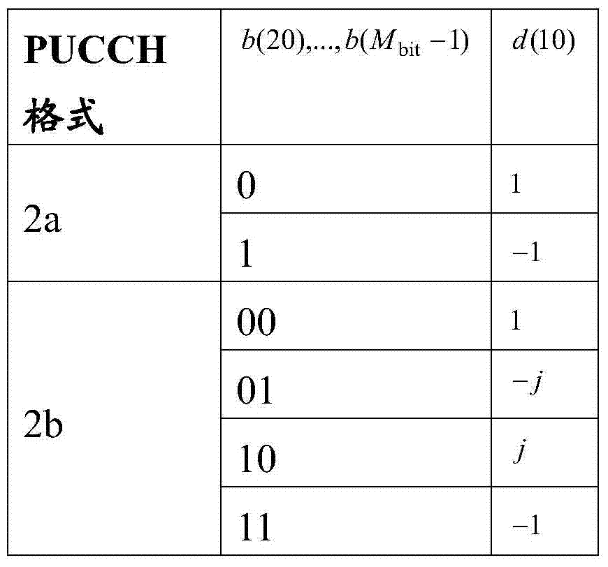
对于仅支持普通的循环前缀的PUCCH格式2a和2b,如表5.4.2-1中描述的来调制比特b(20),...,b(Mbit-1),导致用在如REF1的5.5.2.2.1节中描述的用于PUCCH格式2a和2b的参考信号的生成中的单调制符号d(10)。For PUCCH formats 2a and 2b that only support normal cyclic prefixes, bits b(20),...,b(M bit -1) are modulated as described in Table 5.4.2-1, resulting in Single modulation symbol d(10) in the generation of reference signals for PUCCH formats 2a and 2b described in Section 5.5.2.2.1.
表5.4.2-1:用于格式2a和2b的调制符号d(10)。Table 5.4.2-1: Modulation symbol d(10) for formats 2a and 2b.
REF1的5.4.3节描述了PUCCH映射到物理资源,如下。Section 5.4.3 of REF1 describes the mapping of PUCCH to physical resources as follows.
5.4.3映射到物理资源5.4.3 Mapping to physical resources
复数值符号块与幅度比例因子βPUCCH相乘,以便符合在5.1.2.1节中指定的发送功率PPUCCH,并且按以


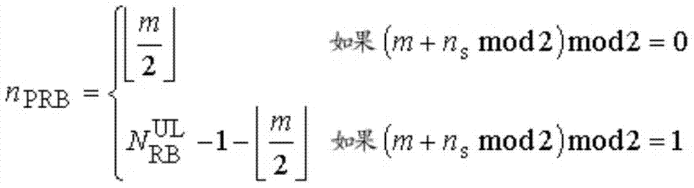
时隙ns中要用于PUCCH的传输的物理资源块由下面提供The physical resource blocks to be used for the transmission of PUCCH in slot n s are given by
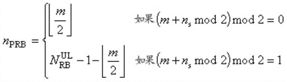
其中变量m取决于PUCCH格式。对于格式1、1a和1bThe variable m depends on the PUCCH format. For

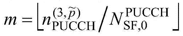
并且对于格式2、2a和2band for

并且对于格式3and for
在图5中示出用于物理上行链路控制信道的调制符号的映射。The mapping of modulation symbols for the physical uplink control channel is shown in FIG. 5 .
在当存在一个被配置的服务小区时具有声探参考信号和PUCCH格式1、1a、1b或3的同时传输的情形中,使用缩短的PUCCH格式,其中子帧的第二时隙中的最后的SC-FDMA符号被留空。In case of simultaneous transmission with sounding reference signal and
在LTE版本11(“Rel-11”)中,可以实施E-PDCCH来增加小区之内的DL控制容量,并用于减轻用于DL控制的小区间干扰。E-PDCCH如图6中所示被置于PDSCH区域中,并且它们向被配置来接收E-PDCCH的Rel-11UE传达DL控制信令。In LTE Release 11 ("Rel-11"), E-PDCCH may be implemented to increase DL control capacity within a cell and to mitigate inter-cell interference for DL control. E-PDCCHs are placed in the PDSCH region as shown in Figure 6, and they convey DL control signaling to Rel-11 UEs configured to receive E-PDCCHs.
在36.331v10.1.0中,对于CSI-RS定义了配置。信息单元(IE)CSI-RS-Config用来指定CSI(信道状态信息)参考信号配置。In 36.331v10.1.0, configurations are defined for CSI-RS. The information element (IE) CSI-RS-Config is used to specify the CSI (channel state information) reference signal configuration.
CSI-RS-Config信息单元CSI-RS-Config information element

REF1如下描述CSI-RS映射到资源单元:REF1 describes the mapping of CSI-RS to resource elements as follows:
6.10.5.2映射到资源单元6.10.5.2 Mapping to resource units
在配置用于CSI参考信号传输的子帧中,根据如下将参考信号序列映射到用作天线端口p上的参考符号的复数值的调制符号
其中in
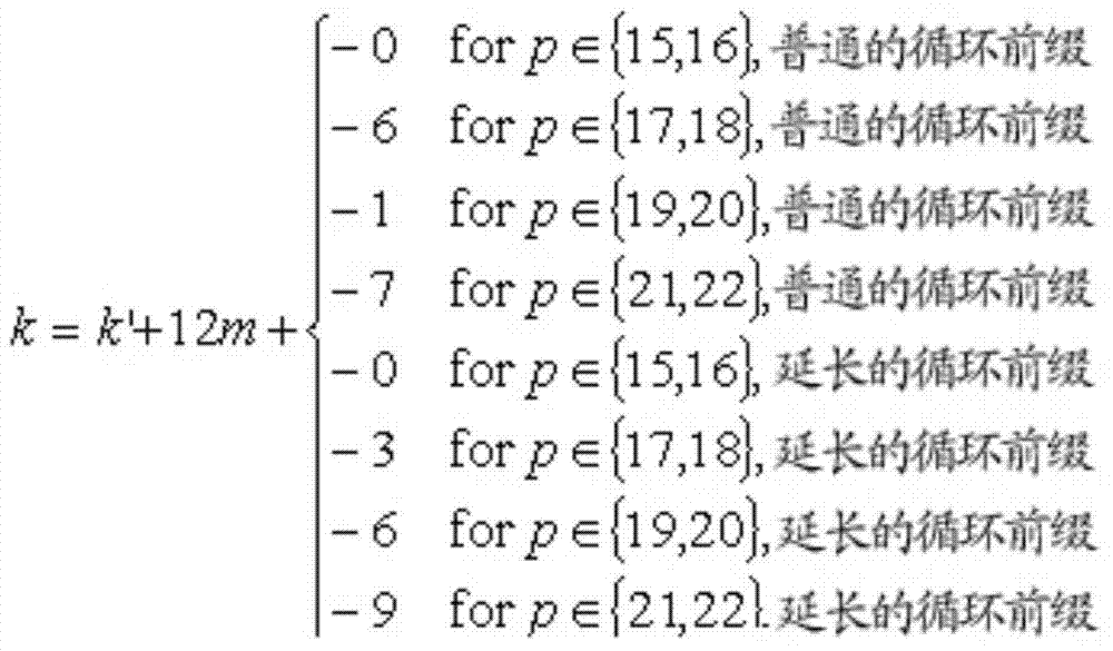
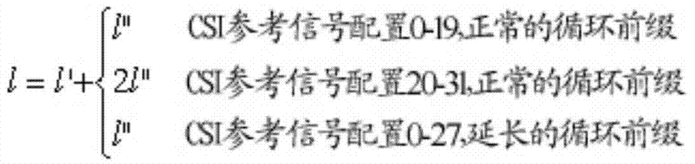
l″=0,1l″=0,1

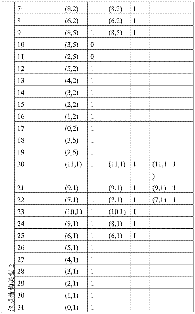
量(k',l')和关于ns的必要条件由表1提供,用于普通的循环前缀。The quantities (k',l') and the necessary conditions on n s are given in Table 1 for ordinary cyclic prefixes.
表1Table 1
从CSI参考信号配置到(k',l')的配置,用于普通的循环前缀From CSI reference signal configuration to (k',l') configuration for common cyclic prefix

6.10.5.3CSI参考信号子帧配置6.10.5.3 CSI reference signal subframe configuration
用于CSI参考信号的出现的小区特定的子帧配置周期TCSI-RS和小区特定的子帧偏移ΔCSI-RS在下面的表2中列出。参数ICSI-RS可以单独地被配置用于CSI参考信号,对于CSI参考信号UE假设非零和零传输功率。包含CSI参考信号的子帧满足
表2CSI参考信号子帧配置Table 2 CSI reference signal subframe configuration

下行链路软小区划分–基于CSI-RS配置参数的UE-RS加扰Downlink soft cell division – UE-RS scrambling based on CSI-RS configuration parameters
图7示出根据此公开的实施例的协作多点场景,其中将一个物理小区ID分配给宏小区和许多射频拉远头(RRH)。如图7中所示,LTE-A Rel-11CoMP(协作多点)场景(一般被称为“CoMP场景4”)包括中央控制器,其控制在宏覆盖中的许多传输点(TP)(宏0、RRH1和RRH2)。将一个物理小区ID,分配给宏和RRH。许多UE(UE0至UE3)与宏和RRH的一个或多个通信。在一些实施例中,宏0、RRH1、和RRH2的每个可以表示图1中的eNB101-103中的一个或多个。同样地,每个UE,UE0至UE3可以表示图1中的UE111-116中的一个或多个。在一些实施例中,RRH1和RRH2可以表示微微小区站、毫微微小区站、或者具有小覆盖区域的任何其他基站。Figure 7 shows a coordinated multipoint scenario according to an embodiment of this disclosure, where one physical cell ID is allocated to a macro cell and many Remote Radio Heads (RRHs). As shown in Figure 7, the LTE-A Rel-11 CoMP (Coordinated Multipoint) scenario (generally referred to as "CoMP Scenario 4") includes a central controller that controls many transmission points (TPs) in macro coverage (
根据传统LTE规范(3GPP LTE Rel-10),不管UE从哪个TP接收DL数据信号,UE都会期待UE特定的解调参考信号(UE-RS)根据在初始接入过程期间获得的物理小区ID而被加扰。在3GPP TS36.211v1.0.0.0的6.10.3.1节中,关于如下的UE-RS的加扰来描述接下来的UE行为。According to the legacy LTE specification (3GPP LTE Rel-10), regardless of which TP the UE receives the DL data signal from, the UE expects a UE-specific demodulation reference signal (UE-RS) according to the physical cell ID obtained during the initial access procedure while being scrambled. In Section 6.10.3.1 of 3GPP TS36.211v1.0.0.0, the following UE behavior is described regarding scrambling of UE-RS as follows.
在每个子帧的开始处,使用
根据上述UE行为,如果宏0、RRH1和RRH2同时在相同的频带向不同的UE(即,UE0、UE1、UE2和UE3,如图7中所示)发送,则在每个UE处接收到的来自其他TP的干扰会相干地添加到期望的信号,从而每个UE不能区分期望的信号和干扰信号。According to the UE behavior described above, if
为解决此问题,提出了很多软小区分裂(splitting)技术,例如,向从不同TP接收的UE分配不同的UE-RS加扰初始化。当实施一种软小区分裂技术时,UE1、UE2和UE3在接收不同的经加扰的UE-RS,如图7中所示。To solve this problem, many soft cell splitting techniques have been proposed, for example, assigning different UE-RS scrambling initializations to UEs received from different TPs. When implementing a soft cell splitting technique, UE1, UE2 and UE3 are receiving different scrambled UE-RSs, as shown in FIG. 7 .
下面提供根据此公开的实施例的用于动态软小区分裂的以下方法。The following methods for dynamic soft cell splitting according to embodiments of this disclosure are provided below.
方法1:对于被配置为实施软小区划分的UE,至少部分取决于UE的CSI-RS配置的resourceConfig、subframeConfig和antennaPortsCount中的至少一个,例如,上面定义的IE CSI-RS-Config,来初始化UE-RS加扰。这里,Method 1: For a UE configured to implement soft cell division, initialize the UE depending at least in part on at least one of resourceConfig, subframeConfig, and antennaPortsCount of the UE's CSI-RS configuration, e.g., the IE CSI-RS-Config defined above -RS scrambling. here,
根据表1,subframeConfig∈{0,1,...31}确定在哪些子帧上发送CSI-RS;According to Table 1, subframeConfig∈{0,1,...31} determines on which subframes to send CSI-RS;
antennaPortsCount∈{1,2,4,8}确定发送CSI-RS所针对的天线端口的数目;antennaPortsCount ∈ {1,2,4,8} determines the number of antenna ports for which the CSI-RS is transmitted;
根据表2,resourceConfig∈{0,1,...154}确定与关于发送CSI-RS所在的子帧的antennaPortsCount对应的CSI-RS图案。According to Table 2, resourceConfig∈{0,1,...154} determines the CSI-RS pattern corresponding to the antennaPortsCount about the subframe where the CSI-RS is transmitted.
换言之,用于UE-RS加扰的cinit被定义为resourceConfig(RC)、subframeConfig(SC,或者ICSI-RS)和antennaPortsCount(APC)中至少一个的函数。In other words, c init for UE-RS scrambling is defined as a function of at least one of resourceConfig (RC), subframeConfig (SC, or ICSI-RS ) and antennaPortsCount (APC).
方法1包括很多益处。一个益处是除了用于CoMP场景4操作的CSI-RS配置的信令之外,不需要(或需要极少)另外的信令来配置UE-RS加扰初始化用于促进软小区划分。另一个益处是CSI-RS配置很可能在TP之间不同,因为不同的TP用不同的时间-频率资源来发送CSI-RS是普遍的。依靠此属性,方法1确保从不同的TP接收DL信号的UE接收带有不同的经加扰的UE-RS的DL信号。
为了方法1的图解,考虑图7,其中宏0根据CSI-RS配置1发送CSI-RS,RRH1根据CSI-RS配置2发送CSI-RS,并且RRH2根据CSI-RS配置3发送CSI-RS,其中三个CSI-RS配置定义如下。For illustration of
CSI-RS配置1至少包括以下字段:CSI-
resourceConfig=RC1resourceConfig=RC1
subframeConfig=SC1subframeConfig=SC1
antennaPortCount=APC1。antennaPortCount=APC1.
CSI-RS配置2至少包括以下字段:CSI-
resourceConfig=RC2resourceConfig=RC2
subframeConfig=SC2subframeConfig=SC2
antennaPortCount=APC2。antennaPortCount=APC2.
CSI-RS配置3至少包括以下字段:CSI-
resourceConfig=RC3resourceConfig=RC3
subframeConfig=SC3subframeConfig=SC3
antennaPortCount=APC3。antennaPortCount=APC3.
在图7中,UE1、UE2和UE3是高级UE,不但实施了Rel-10特征而且实施了在Rel-11中引入的新的特征。In Fig. 7, UE1, UE2 and UE3 are advanced UEs, implementing not only Rel-10 features but also new features introduced in Rel-11.
在一个实施例(下文中称为实施例0)中,UE0不被配置为进行软小区划分,并被配置有CSI-RS配置1。UE0接收带有通过Rel-9加扰序列加扰码的UE-RS的PDSCH,该加扰序列如上述以
在一个示例中,UE0是Rel-9UE。在另一示例中,UE0是Rel-10UE。在又一示例中,UE0是Rel-11UE,其尚未接收实施软小区划分的信令。In one example, UE0 is a Rel-9 UE. In another example, UE0 is a Rel-10 UE. In yet another example, UE0 is a Rel-11 UE that has not received signaling to implement soft cell division.
在一个实施例(下文中称为实施例1)中,UE0被配置为进行软小区划分,并被配置有CSI-RS配置1。UE1接收具有通过加扰序列加扰的UE-RS的PDSCH,该加扰序列以初始化,其中nSCID2是RC1、SC1和APC1中的至少一个的函数。这里,nSCID2乘以2使得初始化cinit根据nSCID2变化而独立于nSCID,其为1比特的量。确定nSCID2的一些示例列出如下:In one embodiment (hereinafter referred to as embodiment 1), UE0 is configured to perform soft cell division and is configured with CSI-
nSCID2=g(RC):在此情况中,nSCID2仅取决于CSI-RS图案。n SCID2 =g(RC): In this case, n SCID2 depends only on the CSI-RS pattern.
nSCID2=g(RC)·(ICSI-RSmod5):这里,应用(ICSI-RS mod5)来确保使用ICSI-RS的可能值至多产生5个不同的加扰初始化,其中5对应于用于CSI-RS子帧的最小可配置周期。在此情况中,nSCID2是8比特的量。n SCID2 = g(RC) (I CSI-RS mod5): Here, (I CSI-RS mod 5) is applied to ensure that at most 5 different scrambling initializations are produced using possible values of I CSI-RS , where 5 corresponds to Minimum configurable period for CSI-RS subframe. In this case, n SCID2 is an amount of 8 bits.
nSCID2=g(RC)·(ICSI-RSmod80):这里,应用(ICSI-RS mod80)来确保使用ICSI-RS的可能值至多生成80个不同的加扰初始化,其中80对应于用于CSI-RS子帧的最大可配置周期。在此情况中,nSCID2是12比特的量。n SCID2 = g(RC) (I CSI-RS mod80): Here, (I CSI-RS mod 80) is applied to ensure that at most 80 different scrambling initializations are generated using possible values of I CSI-RS , where 80 corresponds to Maximum configurable period for CSI-RS subframes. In this case, n SCID2 is an amount of 12 bits.
nSCID2=g(RC)·ΔCSI-RS:这里,应用ΔCSI-RS来确保使用ICSI-RS的可能值至多生成TCSI-RS个不同的加扰初始化。n SCID2 =g(RC)·ΔCSI -RS : Here, ΔCSI-RS is applied to ensure that at most T CSI -RS different scrambling initializations are generated using possible values of ICSI-RS .
在这些示例中,ΔCSI-RS和TCSI-RS是使用表2从ICSI-RS=SC1导出的CSI-RS子帧偏移和周期。In these examples, Δ CSI-RS and T CSI-RS are the CSI-RS subframe offset and period derived from ICSI -RS = SC1 using Table 2.
确定函数g(RC)的一些选择列出如下:Some options for determining the function g(RC) are listed below:
g(RC)=RC:在此情况中,取决于FDD情况中对应的1端口或2端口CSI-RS图案,g(RC)会具有20个可能的值。g(RC)=RC: In this case g(RC) would have 20 possible values depending on the corresponding 1-port or 2-port CSI-RS pattern in the FDD case.
g(RC)=RCmod10:在此情况中,取决于FDD情况下对应的4端口CSI-RS图案,g(RC)会具有10个可能值,即,如果两个CSI-RS图案属于相同的4端口CSI-RS图案,则两个1端口或2端口CSI-RS图案会导致相同的g(RC)。g(RC)=RCmod10: In this case g(RC) will have 10 possible values depending on the corresponding 4-port CSI-RS pattern in the FDD case, i.e. if two CSI-RS patterns belong to the same 4-port port CSI-RS pattern, then two 1-port or 2-port CSI-RS patterns result in the same g(RC).
在另一个实施例(下文中称为实施例2)中,UE1被配置为进行软小区划分,并被配置有CSI-RS配置1。UE1接收具有通过加扰序列加扰的UE-RS的PDSCH,该加扰序列以
在第一选择(选择1)中,在无线资源控制(RRC)层中半静态地信号通知参数X。在第二选择(选择2)中,用DCI格式动态地信号通知参数X。In a first option (Option 1 ), the parameter X is signaled semi-statically in the Radio Resource Control (RRC) layer. In a second option (option 2), the parameter X is dynamically signaled in DCI format.
确定nSCID2的一些示例列出如下,其中


类似于实施例2,确定的一些示例列出如下:Similar to Example 2, determine Some examples of are listed below:
在这些示例中,ΔCSI-RS是使用表2从ICSI-RS=SC1导出的CSI-RS子帧偏移。In these examples, ΔCSI-RS is the CSI-RS subframe offset derived from ICSI-RS = SC1 using Table 2.
确定函数g(RC)的一些选择列出如下:Some options for determining the function g(RC) are listed below:
g(RC)=RCg(RC)=RC
g(RC)=RCmod10。g(RC)=RCmod10.
在另一实施例(下文中称为实施例3)中,对于CoMP操作,UE2被配置为进行软小区划分,并且被配置有两种CSI-RS配置,即,CSI-RS配置1和CSI-RS配置2。在此实施例中,UE2识别两种配置中的一种CSI-RS配置来确定nSCID2。一旦确定一种CSI-RS配置,UE2就基于这一种CSI-RS配置的字段值来计算nSCID2,并且接收以加扰的UE-RS。在实施例1和2中列出nSCID2的一些示例。下面列出UE在两种配置中确定要用于确定nSCID2的一种CSI-RS配置的示例方法。In another embodiment (hereinafter referred to as embodiment 3), for CoMP operation, UE2 is configured for soft cell division and configured with two CSI-RS configurations, namely, CSI-
在一个示例中,要确定nSCID2的一种CSI-RS配置是UE从其接收E-PDCCH的主要TP的CSI-RS配置。在另一示例中,确定nSCID2的一种CSI-RS配置通过RRC信令来明确地标识。In one example, one CSI-RS configuration for which n SCID2 is to be determined is the CSI-RS configuration of the primary TP from which the UE receives the E-PDCCH. In another example, a CSI-RS configuration for determining n SCID2 is explicitly identified through RRC signaling.
在一种方法中,RRC信令标识配置到UE的多个CSI-RS配置当中的单个主要的CSI-RS配置。在此情况中,主要CSI-RS配置中的字段值确定nSCID2。例如,当UE2接收标识CSI-RS配置1是主要CSI-RS配置的RRC信令时,UE2接收以初始化
标识CSI-RS配置1是主要CSI-RS配置的一个示例RRC信令设计是在每个CSI-RS配置中引入1比特标记字段(例如,primaryFlag),指示该CSI-RS配置是否是主要的。如果primaryFlag=1,那么关联的CSI-RS配置是主要的。如果primaryFlag=0,那么关联的CSI-RS配置是非主要的。下面显示这样的RRC信令消息的示例,其中RRC信令消息包括两种CSI-RS配置,即,CSI-RS配置1和CSI-RS配置2,并且通过设置primaryFlag=1,CSI-RS配置1(csi-RS1)被标记为主要配置。One example RRC signaling design to identify CSI-

在另一种方法中,一个RRC信令消息包括如下所示的两种CSI-RS配置,即,CSI-RS配置1和CSI-RS配置2。该信令消息发送给UE2。然后,UE2将使用RRC信令消息中的第一CSI-RS配置,即,CSI-RS配置1来确定nSCID2。In another method, one RRC signaling message includes two CSI-RS configurations as shown below, namely, CSI-

确定nSCID2的这一CSI-RS配置具有最小的g(RC)。在g(RC)=RC的一个示例中,当RC1=7并且RC2=15时,UE2使用CSI-RS配置1用于确定nSCID2。在g(RC)=RCmod10的另一示例中,当RC1=7并且RC2=15时,UE2使用CSI-RS配置2用于确定nSCID2。This CSI-RS configuration of n SCID2 is determined to have the smallest g(RC). In an example where g(RC)=RC, when RC1=7 and RC2=15, UE2 uses CSI-
确定nSCID2的这一种CSI-RS配置具有最小的周期,即,TCSI-RS,其中TCSI-RS是在表2中用ICSI-RS=SC导出的CSI-RS周期。例如,当SC1提供TCSI-RS=5并且SC2提供TCSI-RS=10时,UE2使用CSI-RS配置1用于确定nSCID2。This CSI-RS configuration of n SCID2 is determined to have the smallest period, ie T CSI-RS , where T CSI-RS is the CSI-RS period derived in Table 2 with I CSI-RS = SC. For example, when SC1 provides T CSI-RS =5 and SC2 provides T CSI-RS =10, UE2 uses CSI-
确定nSCID2的这一种CSI-RS配置具有最大的周期,即,TCSI-RS。其中TCSI-RS是在表2中使用ICSI-RS=SC导出的CSI-RS周期。例如,当SC1提供TCSI-RS=5并且SC2提供TCSI-RS=10时,UE2使用CSI-RS配置2用于确定nSCID2。It is determined that such a CSI-RS configuration of n SCID2 has the largest period, ie T CSI-RS . where T CSI-RS is the CSI-RS period derived using I CSI-RS =SC in Table 2. For example, when SC1 provides T CSI-RS =5 and SC2 provides T CSI-RS =10, UE2 uses CSI-
确定nSCID2的这一种CSI-RS配置具有最小的偏移,即,ΔCSI-RS,其中ΔCSI-RS是在表2中用ICSI-RS=SC导出的CSI-RS子帧偏移。例如,当SC1提供ΔCSI-RS=5并且SC2提供ΔCSI-RS=10时,UE2使用CSI-RS配置1用于确定nSCID2。This CSI-RS configuration that determines n SCID2 has the smallest offset, i.e., ΔCSI-RS , where ΔCSI-RS is the CSI-RS subframe offset derived in Table 2 with I CSI-RS = SC . For example, when SC1 provides Δ CSI-RS =5 and SC2 provides Δ CSI-RS =10, UE2 uses CSI-
确定nSCID2的这一种CSI-RS配置具有最大的偏移,即,ΔCSI-RS,其中ΔCSI-RS是在表2中用ICSI-RS=SC导出的CSI-RS子帧偏移。例如,当SC1提供ΔCSI-RS=5并且SC2提供ΔCSI-RS=10时,UE2使用CSI-RS配置2用于确定nSCID2。Determine that this CSI-RS configuration of n SCID2 has the largest offset, i.e., ΔCSI-RS , where ΔCSI-RS is the CSI-RS subframe offset derived in Table 2 with I CSI-RS = SC . For example, when SC1 provides Δ CSI-RS =5 and SC2 provides Δ CSI-RS =10, UE2 uses CSI-
上行链路软小区划分–基于CSI-RS配置参数的UL RS基本序列初始化Uplink Soft Cell Division – UL RS Basic Sequence Initialization Based on CSI-RS Configuration Parameters
当对于上行链路实施软小区划分时,两个基本RS序列被配置为对于向不同的TP发送上行链路信号的两个UE不同,而所有的TP仍然可以用相同的小区ID来操作。在图8中示出用于UL的软小区划分。如图8中所示,宏0、RRH1和RRH2以相同的小区ID,即
下面提供根据此公开的实施例的用于促进UL软小区划分的以下方法。The following methods for facilitating UL soft cell partitioning according to embodiments of this disclosure are provided below.
方法2:至少部分取决于UE的CSI-RS配置(例如,上面定义的CSI-RS-Config)中的resourceConfig(RC)、subframeConfig(SC)和antennaPortsCount(APC)中的至少一个,被配置为进行软小区划分的UE生成UL RS基本序列。这里,Method 2: Depending at least in part on at least one of resourceConfig(RC), subframeConfig(SC) and antennaPortsCount(APC) in the UE's CSI-RS configuration (eg, CSI-RS-Config defined above), configured to perform The UE in the soft cell division generates UL RS basic sequences. here,
根据上面的表1,subframeConfig∈{0,1,...31}确定发送CSI-RS所在的子帧;According to Table 1 above, subframeConfig∈{0,1,...31} determines the subframe where the CSI-RS is sent;
antennaPortsCount∈{1,2,4,8}确定发送CSI-RS所用于的天线端口的数目;antennaPortsCount ∈ {1,2,4,8} determines the number of antenna ports used to transmit the CSI-RS;
根据上面的表2,resourceConfig∈{0,1,...154}确定与关于发送CSI-RS所在的子帧的antennaPortsCount对应的CSI-RS图案。According to Table 2 above, resourceConfig∈{0,1,...154} determines the CSI-RS pattern corresponding to the antennaPortsCount about the subframe where the CSI-RS is transmitted.
在一个示例中,至少部分取决于UE的CSI-RS配置的RC、SC和APC,UE生成它的基本序列
为了方法2的图解,考虑图8,其中宏0根据CSI-RS配置1发送CSI-RS,RRH1根据CSI-RS配置2发送CSI-RS,并且RRH2根据CSI-RS配置3发送CSI-RS,其中三个CSI-RS配置定义如下。For illustration of
CSI-RS配置1至少包括以下字段:CSI-
resourceConfig=RC1resourceConfig=RC1
subframeConfig=SC1subframeConfig=SC1
antennaPortCount=APC1。antennaPortCount=APC1.
CSI-RS配置2至少包括以下字段:CSI-
resourceConfig=RC2resourceConfig=RC2
subframeConfig=SC2subframeConfig=SC2
antennaPortCount=APC2。antennaPortCount=APC2.
CSI-RS配置3至少包括以下字段:CSI-
resourceConfig=RC3resourceConfig=RC3
subframeConfig=SC3subframeConfig=SC3
antennaPortCount=APC3。antennaPortCount=APC3.
在图8中,UE1、UE2和UE3是高级UE,不但实施了Rel-10特征而且实施了在Rel-11中引入的新的特征。In FIG. 8 , UE1 , UE2 and UE3 are advanced UEs implementing not only Rel-10 features but also new features introduced in Rel-11.
在一个实施例(下文中称为实施例0A)中,UE0不被配置为进行软小区划分,并被配置有CSI-RS配置1。UE0发送使用基本序列
在一个示例中,UE0是Rel-8UE。在另一示例中,UE0是Rel-9UE。在又一示例中,UE0是Rel-10UE。在又另一示例中,UE0是Rel-11UE,其尚未接收到实施软小区划分的信令。In one example, UE0 is a Rel-8 UE. In another example, UE0 is a Rel-9 UE. In yet another example, UE0 is a Rel-10 UE. In yet another example, UE0 is a Rel-11 UE that has not received signaling to implement soft cell division.
在一个实施例(下文中称为实施例4)中,UE0被配置为进行软小区划分,并被配置有CSI-RS配置1。UE1发送使用基本序列
u=(fgh(ns)+fss+g(RC))mod30;u=(f gh (n s )+f ss +g(RC))mod30;
u=(fgh(ns)+fss+g(RC)·ΔCSI-RS)mod30;u=(f gh (n s )+f ss +g(RC)·Δ CSI-RS )mod30;
u=(fgh(ns)+fss+g(RC)·(ICSI-RSmod5))mod30;u=(f gh (n s )+f ss +g(RC)·(I CSI-RS mod5))mod30;
u=(fgh(ns)+fss+g(RC)·(ICSI-RSmod80))mod30;u=(f gh (n s )+f ss +g(RC)·(I CSI-RS mod80))mod30;
其中ΔCSI-RS是使用ICSI-RS=SC1在表2中定义的CSI-RS子帧偏移,并且ICSI-RS=SC1。组跳频图案fgh(ns)对于PUSCH和PUCCH是相同的,并且由如下提供where ΔCSI -RS is the CSI-RS subframe offset defined in Table 2 using ICSI-RS = SC1 and ICSI-RS = SC1 . The group hopping pattern f gh (n s ) is the same for PUSCH and PUCCH and is given by

其中伪随机序列c(i)通过7.2节定义。在每个无线帧的开始处以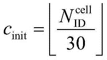
序列移位图案fss定义在PUCCH和PUSCH之间不同。对于PUCCH,序列移位图案由
确定g(RC)的一些选择列出如下:Some options for determining g(RC) are listed below:
g(RC)=RC。g(RC)=RC.
g(RC)=RCmod10。g(RC)=RCmod10.
在另一个实施例(下文中称为实施例5)中,UE1被配置为进行软小区划分,并被配置有CSI-RS配置1。UE1发送使用基本序列生成的PUSCH DM-RS和PUCCH中的至少一个,其中根据u=(fgh(ns)+fss)mod30来生成序列组数目u。In another embodiment (hereinafter referred to as embodiment 5), UE1 is configured to perform soft cell division and is configured with CSI-
这里,序列移位图案fss根据Rel-8UE行为来确定。对于PUCCH,序列移位图案

取决于RC1、APC1和SC1中的至少一个来确定组跳频图案fgh(ns)。类似于传统系统,根据如下来确定fgh(ns),The group hopping pattern f gh (n s ) is determined depending on at least one of RC1 , APC1 and SC1 . Similar to conventional systems, f gh (n s ) is determined according to,

但是不同地初始化伪随机序列c(i)。用于确定用于伪随机序列c(i)的初始化种子cinit的一些示例等式列出如下:But initialize the pseudo-random sequence c(i) differently. Some example equations for determining the initialization seed c init for the pseudo-random sequence c(i) are listed below:

这里,

这里,ΔCSI-RS是使用ICSI-RS=SC1在表2中定义的SCI-RS子帧偏移;ICSI-RS=SC1;并且g(RC)是RC=RC1的函数。确定g(RC)的一些选择列出如下:Here, ΔCSI-RS is the SCI-RS subframe offset defined in Table 2 using ICSI-RS =SC1; ICSI-RS =SC1; and g(RC) is a function of RC=RC1. Some options for determining g(RC) are listed below:
g(RC)=RCg(RC)=RC
g(RC)=RCmod10。g(RC)=RCmod10.
在另一个实施例(下文中称为实施例6)中,UE1被配置为进行软小区划分,并被配置有CSI-RS配置1。UE1发送使用基本序列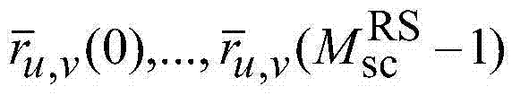
这里,fgh(ns)根据Rel-8UE行为来确定:Here, f gh (n s ) is determined from Rel-8 UE behavior:

并且在每个无线帧的开始处使用
取决于RC1、SC1和APC1中的至少一个来确定PUCCH序列移位图案
这里,是RC=RC1、SC=SC1、APC=APC1的函数。类似于实施例2,确定
这里,ΔCSI-RS是使用ICSI-RS=SC1在表2中定义的CSI-RS子帧偏移;ICSI-RS=SC1;并且g(RC)是RC=RC1的函数。确定g(RC)的一些选择列出如下:Here, ΔCSI -RS is the CSI-RS subframe offset defined in Table 2 using ICSI-RS = SC1; ICSI-RS = SC1; and g(RC) is a function of RC = RC1. Some options for determining g(RC) are listed below:
g(RC)=RCg(RC)=RC
g(RC)=RCmod10。g(RC)=RCmod10.
对于PUSCH序列移位图案

其中Δss∈{0,1,...,29}通过更高层来配置。where Δ ss ∈ {0,1,...,29} is configured by higher layers.
在另一选择中,根据Rel-8UE行为来确定PUSCH序列移位图案,使得软小区划分不应用于PUSCH:In another option, the PUSCH sequence shift pattern is determined according to Rel-8 UE behavior, so that soft cell division is not applied to PUSCH:
在另一个实施例(下文中称为实施例7)中,UE1被配置为进行软小区划分,并被配置有CSI-RS配置1。UE1发送使用基本序列
这里,fgh(ns)根据Rel-8UE行为来确定:Here, f gh (n s ) is determined from Rel-8 UE behavior:

并且在每个无线帧的开始处使用
根据Rel-8UE行为来确定PUCCH序列移位图案
取决于RC1、SC1、和APC1中的至少一个来确定PUSCH序列移位图案
这里,ΔCSI-RS是使用ICSI-RS=SC1在表2中定义的CSI-RS子帧偏移;并且ICSI-RS=SC1。Here, ΔCSI -RS is the CSI-RS subframe offset defined in Table 2 using ICSI-RS = SC1; and ICSI-RS = SC1.
确定g(RC)的一些选择列出如下:Some options for determining g(RC) are listed below:
g(RC)=RC,在这种情况中,取决于FDD情况中对应的1端口或2端口CSI-RS图案,g(RC)会具有20个可能值。g(RC)=RC, in this case g(RC) would have 20 possible values depending on the corresponding 1-port or 2-port CSI-RS pattern in the FDD case.
g(RC)=RCmod10,在这种情况中,取决于FDD情况中对应的4端口CSI-RS图案,g(RC)会具有10个可能值,即,如果两个CSI-RS图案属于相同的4端口CSI-RS图案,则两个1端口或2端口CSI-RS图案会导致相同的g(RC)。g(RC)=RCmod10, in this case g(RC) will have 10 possible values depending on the corresponding 4-port CSI-RS pattern in the FDD case, i.e. if two CSI-RS patterns belong to the same 4-port CSI-RS pattern, then two 1-port or 2-port CSI-RS patterns result in the same g(RC).
这些用于
在另一个实施例(下文中称为实施例8)中,UE1被配置有CSI-RS配置1。UE1发送使用基本序列
这里,fgh(ns)根据Rel-8UE行为来确定:Here, f gh (n s ) is determined from Rel-8 UE behavior:
并且在每个无线帧的开始处使用
至少部分取决于RC1、APC1、和SC1来确定PUCCH序列移位图案


在另一个实施例(下文中称为实施例9)中,UE1被配置为进行软小区划分,并被配置有CSI-RS配置1。UE1发送使用基本序列
假设
假设是RC=RC1、SC=SC1、APC=APC1的函数,用于根据实施例5基于RC1、SC1、APC1和X来确定cinit和u∈{0,1,...,29}的一些示例等式列出如下:

假设

假设
确定
这里,ΔCSI-RS是使用ICSI-RS=SC1在表2中定义的CSI-RS子帧偏移;ICSI-RS=SC1;并且g(RC)是RC=RC1的函数。确定g(RC)的一些选择列出如下:Here, ΔCSI -RS is the CSI-RS subframe offset defined in Table 2 using ICSI-RS = SC1; ICSI-RS = SC1; and g(RC) is a function of RC = RC1. Some options for determining g(RC) are listed below:
g(RC)=RCg(RC)=RC
g(RC)=RCmod10。g(RC)=RCmod10.
在另一个实施例(下文中称为实施例10)中,UE1被配置为进行软小区划分,并被配置有CSI-RS配置1。UE1发送使用基本序列
在一个示例中,如果信号是PUSCH DM-RS,则UE生成u使得它促进软小区划分。如果信号是PUCCH,则UE根据Rel-8UE行为生成u。如果信号是PUSCH DM-RS,则UE使用RC1、SC1、和APC1根据实施例4至9中的示例生成u∈{0,1,...,29}。如果信号是PUCCH,则UE根据Rel-8过程生成u∈{0,1,...,29}。此方法的一个优点是eNodeB仍然可以正交化从使用不同的CSI-RS配置来配置的不同的UE发送的PUCCH序列,并且同时,系统仍然可以实现用于PUSCH的软小区划分增益。In one example, if the signal is PUSCH DM-RS, the UE generates u such that it facilitates soft cell division. If the signal is PUCCH, the UE generates u according to Rel-8 UE behavior. If the signal is PUSCH DM-RS, the UE uses RC1, SC1, and APC1 to generate u∈{0,1,...,29} according to the examples in Embodiments 4 to 9. If the signal is PUCCH, the UE generates u∈{0,1,...,29} according to the Rel-8 procedure. One advantage of this approach is that the eNodeB can still orthogonalize PUCCH sequences sent from different UEs configured with different CSI-RS configurations, and at the same time, the system can still achieve soft cell division gain for PUSCH.
在另一示例中,如果信号是PUCCH,则UE生成u使得它促进软小区划分。如果信号是PUSCH DM-RS,则UE根据Rel-8UE行为来生成u。如果信号是PUCCH,则UE使用RC1、SC1和APC1根据实施例4至9中的示例来生成u∈{0,1,...,29}。如果信号是PUSCH DM-RS,则UE根据Rel-8过程来生成u∈{0,1,...,29}。此方法的一个优点是eNodeB仍然可以正交化从使用不同的CSI-RS配置来配置的不同的UE发送的PUSCH DM-RS,并且同时,系统仍然可以实现用于PUCCH的软小区划分增益。In another example, if the signal is PUCCH, the UE generates u such that it facilitates soft cell division. If the signal is PUSCH DM-RS, the UE generates u according to the Rel-8 UE behavior. If the signal is PUCCH, the UE uses RC1 , SC1 and APC1 to generate u∈{0,1,...,29} according to the examples in Embodiments 4 to 9. If the signal is PUSCH DM-RS, the UE generates u∈{0,1,...,29} according to the Rel-8 procedure. One advantage of this approach is that the eNodeB can still orthogonalize PUSCH DM-RS transmitted from different UEs configured with different CSI-RS configurations, and at the same time, the system can still achieve soft cell division gain for PUCCH.
在另一实施例(下文中称为实施例11)中,对于CoMP操作,UE2被配置为进行软小区划分,并且被配置有两种CSI-RS配置,即,CSI-RS配置1和CSI-RS配置2。在此实施例中,UE2识别两种配置中的一种CSI-RS配置来确定用于促进软小区划分的序列组数目u∈{0,1,...,29}。一旦确定了这一种CSI-RS配置,UE2就基于这一种CSI-RS配置的字段值来计算u∈{0,1,...,29},并且发送使用基本序列生成的PUCCH和PUSCH DM-RS中的至少一个,其中计算u∈{0,1,...,29}的一些示例方法在实施例4至10中描述。用于UE2确定两种配置中的要用于确定u∈{0,1,...,29}的一种CSI-RS配置的示例方法在实施例3中描述。In another embodiment (hereinafter referred to as embodiment 11), for CoMP operation, UE2 is configured for soft cell division and configured with two CSI-RS configurations, namely, CSI-
在另一个实施例(下文中称为实施例12)中,UE1被配置为进行软小区划分,并被配置有CSI-RS配置1并且被调度为发送PUSCH。然后UE1发送使用基本序列
当PUSCH分配尺寸是

其中在每个无线帧的开始处使用

在第一选择(选择1)中,根据

UL/DL软小区划分–软小区划分的配置UL/DL soft cell division – configuration of soft cell division
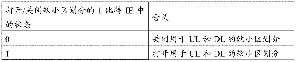
在一个实施例中,如果图7或图8中的UE1在RRC层接收到指示执行软小区划分的信息单元(IE),那么UE1被配置为进行软小区划分用于下行链路UE-RS并用于上行链路RS/PUCCH。在一个示例中,IE是1比特字段,如表3中所示切换软小区划分的开或关。In one embodiment, if UE1 in FIG. 7 or FIG. 8 receives an information element (IE) indicating to perform soft cell division at the RRC layer, UE1 is configured to perform soft cell division for downlink UE-RS and use on the uplink RS/PUCCH. In one example, the IE is a 1-bit field that toggles soft cell division on or off as shown in Table 3.
表3软小区划分的明确的指示Table 3 Clear indication of soft cell division
在另一实施例中,如果图7或图8中的UE1接收到Rel-11CSI-RS配置,那么UE1被配置为进行软小区划分用于下行链路UE-RS并用于上行链路RS/PUCCH。在表4中示出用于切换开或关软小区划分的示例机制。In another embodiment, if UE1 in FIG. 7 or FIG. 8 receives a Rel-11 CSI-RS configuration, then UE1 is configured to perform soft cell division for downlink UE-RS and for uplink RS/PUCCH . An example mechanism for switching soft cell partitioning on or off is shown in Table 4.
表4软小区划分的隐含的指示–TABLE 4 IMPLIED INDICATIONS OF SOFT CELL DIVISION –
CSI-RS配置CSI-RS configuration
在另一实施例中,如果图7或图8中的UE1接收到Rel-11CSI-RS配置,那么UE1被配置为进行软小区划分仅用于下行链路UE-RS。对于其中UL软小区划分没有比无UL软小区划分显著有益的场景,此信令有用。在表5中示出用于切换开或关软小区划分的示例机制。In another embodiment, if UE1 in FIG. 7 or FIG. 8 receives the Rel-11 CSI-RS configuration, then UE1 is configured to perform soft cell division only for downlink UE-RS. This signaling is useful for scenarios where UL soft cell partitioning is not significantly beneficial over no UL soft cell partitioning. An example mechanism for switching soft cell partitioning on or off is shown in Table 5.
表5DL软小区划分的隐含指示–Table 5 Implicit indication of DL soft cell division –
CSI-RS配置CSI-RS configuration
在另一实施例中,如果图7或图8中的UE1被配置为接收E-PDCCH,那么UE1被配置为进行软小区划分用于下行链路UE-RS并用于上行链路RS/PUCCH。在表6中示出用于切换开或关软小区划分的示例机制。In another embodiment, if UE1 in FIG. 7 or FIG. 8 is configured to receive E-PDCCH, then UE1 is configured to perform soft cell division for downlink UE-RS and for uplink RS/PUCCH. An example mechanism for switching soft cell partitioning on or off is shown in Table 6.
表6DL软小区划分的隐含指示–Table 6 Implicit indication of DL soft cell division –
E-PDCCH配置E-PDCCH configuration
在另一实施例中,如果图7或图8中的UE1如在实施例2和9中接收到参数X,那么UE1被配置为进行软小区划分用于下行链路UE-RS并用于上行链路RS。在表7中示出用于切换开或关软小区划分的示例机制。In another embodiment, if UE1 in FIG. 7 or FIG. 8 receives parameter X as in
表7软小区划分的隐含指示–TABLE 7 Implicit indications for soft cell division –
CSI-RS配置CSI-RS configuration
上行链路软小区划分–PUCCH资源分配Uplink Soft Cell Division – PUCCH Resource Allocation
在传统系统(3GPP LTE Rel8、9、10)中,当通过PDCCH动态地调度用于PDSCH的UE的HARQ-ACK反馈时,将携载HARQ-ACK的PUCCH资源(PUCCH格式1a/1b)动态地配置到UE。在这种情况中,用于HARQ-ACK的PUCCH资源数目通过下面的等式来确定:


要用于在时隙ns中的PUCCH的传输的物理资源块通过如下提供:The physical resource blocks to be used for the transmission of the PUCCH in the slot ns are provided by:
其中变量m取决于PUCCH格式。对于格式1、1a和1b:The variable m depends on the PUCCH format. For

在Rel-11系统中,一种类型的UE(类型1)实施用于PUCCH的UL软小区划分,而另一种类型的UE(类型0)不实施。为了减少两种类型的UE之间的干扰和它对系统性能的不利影响,在每个PRB中仅复用一种类型的UE是有益的。图9示出此构思。如图9中所示,PRB#0仅由根据Rel-8机制发送PUCCH的类型0UE来使用。另一方面,PRB#1和PRB#2仅由使用软小区划分来发送PUCCH的类型1UE来使用。In a Rel-11 system, one type of UE (Type 1 ) implements UL soft cell division for PUCCH, while another type of UE (Type 0 ) does not. In order to reduce interference between two types of UEs and its adverse impact on system performance, it is beneficial to multiplex only one type of UEs in each PRB. Figure 9 illustrates this concept. As shown in FIG. 9 ,
在一个实施例中,图7或图8中的UE1被配置为实施软小区划分并被配置有CSI-RS配置1。然后,与通过PDCCH调度的PDSCH对应的UE1的HARQ-ACK的
其中


在一个示例中,


在另一实施例中,在图7或图8中的UE1被配置为实施软小区划分并被配置有CSI-RS配置1。然后,与通过PDCCH调度的PDSCH对应的UE1的HARQ-ACK的

其中


在一个示例中,

在另一实施例中,在图7或图8中的UE1被配置为实施软小区划分并被配置有CSI-RS配置1。然后,与通过PDCCH调度的PDSCH对应的UE1的HARQ-ACK的

在一个示例中,候选的数目N=4,因此在PDCCH中包括两比特信息单元(IE),例如,对应于DL授权。在此示例中,4个候选

表8的动态指示示例1Table 8 Dynamic indication example 1 for

例如,该IE作为明确的2比特字段而被包括在DL授权中。For example, this IE is included in the DL grant as an explicit 2-bit field.
在另一个个示例中,候选的数目N=2,因此在PDCCH中包括一比特信息单元(IE),例如,对应于DL授权。在此情况中,2个候选值通过RRC被配置,并且取决于该IE的值,如在下面的表9中来确定
表9

例如,该IE作为明确的1比特字段而被包括在DL授权中。For example, this IE is included in the DL grant as an explicit 1-bit field.
在另一实施例中,在图7或图8中的UE1被配置为实施软小区划分并被配置有CSI-RS配置1。然后,UE1确定PUCCH格式1/1a/1b资源,并且取决于DL授权的位置,即,是PDCCH还是E-PDCCH用于传达与HARQ-ACK反馈关联的DL授权,来不同地生成它的基本序列。对于E-PDCCH,参照图6。在一个示例中,当UE1在E-PDCCH区域中接收到DL授权时,UE1生成UL RS基本序列用于PUCCH格式1/1a/1b,如表10中所示。In another embodiment, UE1 in FIG. 7 or FIG. 8 is configured to implement soft cell division and is configured with CSI-
表10取决于DL授权位置的基本RS序列生成Table 10 Basic RS sequence generation depending on DL grant position
在REF3的5.1.2节中,PUCCH功率控制描述如下。In section 5.1.2 of REF3, PUCCH power control is described as follows.
如果服务小区c是主要小区,则用于子帧i中的物理上行链路控制信道(PUCCH)传输的UE发送功率PPUCCH的设置由如下定义If the serving cell c is the primary cell, the UE transmit power PUCCH setting for physical uplink control channel (PUCCH) transmission in subframe i is defined by
其中PCMAX,c(i)是用于服务小区c的子帧i中的配置的发送功率。where PCMAX,c (i) is the configured transmit power in subframe i for serving cell c.
参数ΔF_PUCCH(F)由更高层来提供。每个ΔF_PUCCH(F)值对应于与PUCCH格式1a相关的PUCCH格式(F),其中每个PUCCH格式(F)在REF3的表5.4-1中定义。The parameter ΔF_PUCCH (F) is provided by higher layers. Each Δ F_PUCCH (F) value corresponds to a PUCCH format (F) associated with PUCCH format 1a, where each PUCCH format (F) is defined in Table 5.4-1 of REF3.
如果UE被更高层配置为在两个天线端口上发送PUCCH,则ΔTxD(F')的值由更高层来提供,其中每个PUCCH格式F’在REF3的表5.4-1中定义;否则,ΔTxD(F')=0。If the UE is configured by higher layers to transmit PUCCH on two antenna ports, the value of ΔTxD (F') is provided by higher layers, where each PUCCH format F' is defined in Table 5.4-1 of REF3; otherwise, ΔTxD (F')=0.
h(nCQI,nHARQ,nSR)是PUCCH格式从属(dependent)值,其中nCQI对应于在5.2.3.3节中定义的用于信道质量信息的信息比特的数目。如果帧i被配置用于不具有用于UL-SCH的任何相关的传输块的UE的SR,则nSR=1,否则nSR=0。如果UE被配置有一个服务小区,则nHARQ是在子帧i中发送的HARQ比特的数目;否则,在10.1节中定义nHARQ的值。h(n CQI , n HARQ , n SR ) is a PUCCH format dependent value, where n CQI corresponds to the number of information bits for channel quality information defined in Section 5.2.3.3. If frame i is configured for SR for a UE that does not have any associated transport blocks for UL-SCH, then n SR =1, otherwise n SR =0. If the UE is configured with one serving cell, then nHARQ is the number of HARQ bits transmitted in subframe i; otherwise, the value of nHARQ is defined in Section 10.1.
对于PUCCH格式1、1a、和1b,h(nCQI,nHARQ,nSR)=0For PUCCH formats 1, 1a, and 1b, h(n CQI , n HARQ , n SR )=0
对于带有信道选择的PUCCH格式1b,如果UE被配置有多于一个服务小区,则
对于PUCCH格式2、2a、2b,和普通的循环前缀
对于PUCCH格式2和延长的循环前缀
对于PUCCH格式3,如果UE通过更高层配置为在两个天线端口上发送PUCCH,或者如果UE发送多于11比特的HARQ-ACK/SR,则
否则,otherwise,
PO_PUCCH是由更高层提供的参数PO_NOMINAL_PUCCH和更高层提供的参数PO_UE_PUCCH的和组成的参数。 PO_PUCCH is a parameter composed of the sum of the parameter PO_NOMINAL_PUCCH provided by the higher layer and the parameter PO_UE_PUCCH provided by the higher layer.
δPUCCH是UE特定的纠正值,也被称为TPC命令,包括在用于主要小区的DCI格式1A/1B/1D/1/2A/2/2B/2C的PDCCH中,或者与其他UE特定的PUCCH纠正值联合编码地在具有DCI格式3/3A的PDCCH上发送,DCI格式3/3A的CRC奇偶校验位利用TPC-PUCCH-RNTI加扰。δ PUCCH is a UE-specific correction value, also known as a TPC order, included in the PDCCH for DCI format 1A/1B/1D/1/2A/2/2B/2C for the primary cell, or with other UE-specific The PUCCH correction value is jointly coded and sent on the PDCCH with
UE除了在DRX中时,试图在每个子帧上使用UE的TPC-PUCCH-RNTI来解码DCI格式3/3A的PDCCH,并使用UE的C-RNTI(小区无线网络临时标识符)或SPS C-RNTI来解码DCI格式1A/1B/1D/1/2A/2/2B/2C的一个或若干个PDCCH。如果UE解码了用于主要小区的DCI格式1A/1B/1D/1/2A/2/2B/2C的PDCCH并且相应检测到的RNTI等于UE的C-RNTI或SPS C-RNTI,则UE使用在PDCCH中提供的δPUCCH,除非如10.1节中使用DCI格式中的TPC字段来确定PUCCH资源。替换地,如果UE解码DCI格式3/3A的PDCCH,则UE应该使用在那个PDCCH中提供的δPUCCH。否则,UE设置δPUCCH=0dB。Except when the UE is in DRX, it tries to use the UE's TPC-PUCCH-RNTI to decode the PDCCH of
在具有DCI格式1A/1B/1D/1/2A/2/2B/2C的PDCCH上信号通知的δPUCCH dB值在表5.1.2.1-1中提供。如果具有DCI格式1/1A/2/2A/2B/2C的PDCCH被确认为SPS激活PDCCH,或者具有DCI格式1A的PDCCH被确认为SPS释放PDCCH,那么δPUCCH是0dB。具有DCI格式3/3A的在PDCCH上信号通知的δPUCCH dB值作为通过更高层半静态地配置的在表5.1.2.1-1或在表5.1.2.1-2中提供。The delta PUCCH dB values signaled on PDCCH with DCI formats 1A/1B/1D/1/2A/2/2B/2C are provided in Table 5.1.2.1-1. If the PDCCH with
如果PO_UE_PUCCH值通过更高层改变,那么g(0)=0。否则,g(0)=ΔPrampup+δmsg2其中δmsg2是在随机接入响应中指示的TPC命令,见6.2节,并且ΔPrampup是由更高层提供的从第一至最后的前同步码斜坡上升的总功率。If the P O_UE_PUCCH value is changed by higher layers, then g(0)=0. Otherwise, g(0) = ΔP rampup + δ msg2 where δ msg2 is the TPC command indicated in the random access response, see Section 6.2, and ΔP rampup is the ramp from first to last preamble provided by higher layers total power up.
如果对于主要小区UE已达到PCMAX,c,则不累积用于主要小区的正TPC命令。如果UE已达到最小功率,则不累积负TPC命令。当PO_UE_PUCCH值通过更高层改变时,或者当UE接收到随机接入响应消息时,UE重置累积。如果i不是TDD中的上行链路子帧,则g(i)=g(i-1)。If the UE has reached PCMAX,c for the primary cell, no positive TPC commands for the primary cell are accumulated. Negative TPC commands are not accumulated if the UE has reached minimum power. When the P O_UE_PUCCH value is changed by a higher layer, or when the UE receives a random access response message, the UE resets the accumulation. If i is not an uplink subframe in TDD, then g(i)=g(i-1).
表5.1.2.1-1:在DCI格式1A/1B/1D/1/2A/2B/2C/2/3的TPC命令字段到δPUCCH值的映射Table 5.1.2.1-1: Mapping of TPC command fields to delta PUCCH values in DCI format 1A/1B/1D/1/2A/2B/2C/2/3
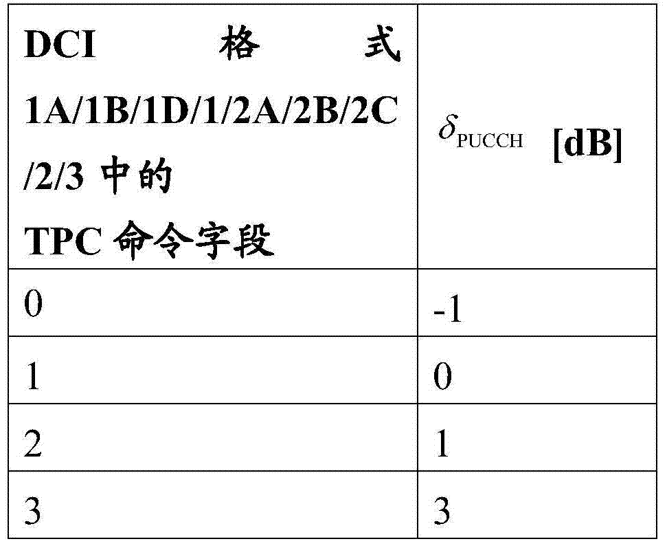
表5.1.2.1-2:在DCI格式3A的TPC命令字段Table 5.1.2.1-2: TPC command field in DCI format 3A
到δPUCCH值的映射Mapping to δ PUCCH values

下行链路动态UE-RS加扰Downlink dynamic UE-RS scrambling
图10示出根据此公开的实施例的异构网络中的下行链路传输。像图7一样,图10示出LTE-A Rel-11CoMP场景4,其中中央控制器控制宏覆盖中的许多传输点(TP)(宏0、RRH1和RRH2)。向宏和RRH分配一个物理小区ID
根据传统LTE规范(3GPP LTE Rel-10),不管UE从哪个TP接收DL数据信号,UE都期望UE特定的解调参考信号(UE-RS)根据在初始接入过程期间获得的物理小区ID
在每个子帧的开始处使用
根据上述UE行为,如果宏0、RRH1和RRH2同时在相同的频带中向不同的UE发送,如图10中所示,则在每个UE处接收到的来自其他TP的干扰会相干地添增加到期望的信号,从而每个UE不能区分期望的信号和干扰信号。According to the UE behavior described above, if
为了减轻此问题,对于Rel-11UE可以引入UE特定的或TP特定的UE-RS加扰。To alleviate this problem, UE-specific or TP-specific UE-RS scrambling can be introduced for Rel-11 UEs.
同时,为了促进Rel-11UE和Rel-10或Rel-9UE的MU-MIMO UE配对,也使用传统的UE-RS加扰用于Rel-11UE可能是有益的。现在描述启动此加扰的两种方法。一种方法是用DL/UL授权DCI格式动态指示UE-RS加扰方法。此方法包括来自UE特定的、TP特定的、和Rel-10兼容的UE-RS加扰中的至少两种的UE-RS加扰方法的动态分配。At the same time, to facilitate MU-MIMO UE pairing of Rel-11 UEs and Rel-10 or Rel-9 UEs, it may be beneficial to also use legacy UE-RS scrambling for Rel-11 UEs. Two methods of initiating this scrambling are now described. One method is to use the DL/UL grant DCI format to dynamically indicate the UE-RS scrambling method. This method includes dynamic allocation of UE-RS scrambling methods from at least two of UE-specific, TP-specific, and Rel-10 compatible UE-RS scrambling.
第二种方法是半静态地指示UE-RS加扰方法。此方法包括来自UE特定的、TP特定的、和Rel-10兼容的UE-RS加扰中的至少两种的UE-RS加扰方法的半静态分配(例如,经由RRC信令)。The second method is to indicate the UE-RS scrambling method semi-statically. This method includes semi-static assignment of UE-RS scrambling methods (eg via RRC signalling) from at least two of UE-specific, TP-specific, and Rel-10 compatible UE-RS scrambling.
图10示出在异构网络中的子帧n和n+1中的示例下行链路传输。UE0是Rel-10UE,而其他UE(UE1、UE2、UE3、UE4和UE5)是Rel-11UE。在图10中示出的网络中,下面的传输发生在子帧n中。Figure 10 shows example downlink transmissions in subframes n and n+1 in a heterogeneous network. UE0 is a Rel-10 UE, while the other UEs (UE1, UE2, UE3, UE4 and UE5) are Rel-11 UEs. In the network shown in Figure 10, the following transmissions occur in subframe n.
在子帧n中,网络在子帧中调度相同的PRB用于UE4和UE5(其中UE4的位置接近RRH1,并且UE5的位置靠近RRH2,其位于远离RRH1),而没有着重考虑干扰功率。此外,借助于不同的UE-RS加扰(初始化),在接收器处不会相干地合并来自RRH1和RRH2的两个UE-RS。网络MU-MIMO复用并分配正交的UE-RS用于Rel-11UE1和Rel-10UE0,而不影响Rel-10UE0的解调性能。网络MU-MIMO复用并分配正交的UE-RS用于两个Rel-11UE:UE2和UE3。In subframe n, the network schedules the same PRB in the subframe for UE4 and UE5 (where UE4 is located close to RRH1, and UE5 is located close to RRH2, which is located far away from RRH1), without focusing on the interference power. Furthermore, the two UE-RSs from RRH1 and RRH2 are not coherently combined at the receiver by means of different UE-RS scrambling (initialization). The network MU-MIMO multiplexes and allocates orthogonal UE-RSs for Rel-11UE1 and Rel-10UE0 without affecting the demodulation performance of Rel-10UE0. The network MU-MIMO multiplexes and allocates orthogonal UE-RSs for two Rel-11 UEs: UE2 and UE3.
替换地,在子帧n+1中,UE1和UE2不接收传输,例如,因为它们完成了数据接收。因为UE数目改变,所以下面的传输发生在子帧n+1中。Alternatively, in subframe n+1, UE1 and UE2 do not receive transmissions, eg, because they have completed data reception. The following transmissions occur in subframe n+1 because the number of UEs changes.
在子帧n+1中,网络在子帧中调度相同的PRB用于UE4和UE5(其中UE4的位置接近RRH1,并且UE5的位置靠近RRH2,其位于远离RRH1),而没有着重考虑干扰功率。此外,借助于不同的UE-RS加扰(初始化),在接收器处不会相干地合并来自RRH1和RRH2的两个UE-RS。网络MU-MIMO复用并分配正交的UE-RS用于Rel-11UE3和Rel-10UE0,而不影响Rel-10UE0的解调性能。In subframe n+1, the network schedules the same PRB in the subframe for UE4 and UE5 (where UE4 is located close to RRH1, and UE5 is located close to RRH2, which is located far away from RRH1), without focusing on the interference power. Furthermore, the two UE-RSs from RRH1 and RRH2 are not coherently combined at the receiver by means of different UE-RS scrambling (initialization). The network MU-MIMO multiplexes and allocates orthogonal UE-RSs for Rel-11UE3 and Rel-10UE0 without affecting the demodulation performance of Rel-10UE0.
为了增加网络吞吐量和实施/调度的灵活性,希望网络能够有效地支持这些多样的并动态改变的传输方案。为了促进此多样和动态的操作,控制信令设计可以用于高级(或Rel-11)UE。In order to increase network throughput and implementation/scheduling flexibility, it is desirable that the network can effectively support these diverse and dynamically changing transmission schemes. To facilitate this diverse and dynamic operation, control signaling design may be used for Advanced (or Rel-11) UEs.
TP特定的加扰的示例Example of TP-specific scrambling
在一个实施例中,对于被配置为接收TP特定地加扰的UE-RS的UE,至少部分取决于UE的CSI-RS配置(例如,上述CSI-RS-Config)的虚拟小区ID、resourceConfig、subframeConfig和antennaPortsCount中的至少一个来初始化UE-RS加扰。这里,根据上面的表1,IE subframeConfig∈{0,1,...31}确定了发送CSI-RS所在的子帧。IE antennaPortsCount∈{1,2,4,8}确定发送CSI-RS针对的天线端口的数目。根据上面的表2,IE resourceConfig∈{0,1,...154}确定与关于发送CSI-RS所在的子帧的antennaPortsCount对应的CSI-RS图案。虚拟小区ID用于初始化加扰序列。在一个示例中,在CSI-RS和UE-RS加扰初始化中,并且在UL RS基本序列生成中(例如,在序列组跳频中等等)虚拟小区ID
换言之,用于UE-RS加扰的cinit被定义为resorceConfig(RC)、subframeConfig(SC,或者ICSI-RS)和antennaPortsCount(APC)中的至少一个的函数。In other words, c init for UE-RS scrambling is defined as a function of at least one of resourceConfig (RC), subframeConfig (SC, or ICSI-RS ), and antennaPortsCount (APC).
在一个示例中,对于被配置为接收TP特定地加扰的UE-RS的UE,至少部分取决于UE的CSI-RS配置(例如,上述CSI-RS-Config)的resourceConfig、subframeConfig和antennaPortsCount中的至少一个来初始化UE-RS加扰。这里,根据表1,IE subframeConfig∈{0,1,...31}确定发送CSI-RS所在的子帧。IE antennaPortsCount∈{1,2,4,8}确定发送CSI-RS所针对的天线端口的数目。根据表2,IE resourceConfig∈{0,1,...154}确定与关于发送CSI-RS所在的子帧的antennaPortsCount对应的CSI-RS图案。In one example, for a UE configured to receive TP-specifically scrambled UE-RS, the resourceConfig, subframeConfig, and antennaPortsCount in resourceConfig, subframeConfig, and antennaPortsCount depend at least in part on the UE's CSI-RS configuration (eg, CSI-RS-Config described above). At least one to initialize UE-RS scrambling. Here, according to Table 1, IE subframeConfig∈{0,1,...31} determines the subframe where the CSI-RS is sent. IE antennaPortsCount ∈ {1,2,4,8} determines the number of antenna ports for which the CSI-RS is sent. According to Table 2, IE resourceConfig ∈ {0,1,...154} determines the CSI-RS pattern corresponding to the antennaPortsCount about the subframe where the CSI-RS is transmitted.
换言之,用于UE-RS加扰的cinit被定义为resourceConfig(RC)、subframeConfig(SC,或者ICSI-RS)和antennaPortsCount(APC)中的至少一个的函数。In other words, c init for UE-RS scrambling is defined as a function of at least one of resourceConfig (RC), subframeConfig (SC, or ICSI-RS ), and antennaPortsCount (APC).
此方法有很多益处。一个益处是除了用于CoMP场景4操作的CSI-RS配置的信令之外,不需要(或需要极少)另外的信令来配置UE-RS加扰初始化用于促进软小区划分。另一个益处是CSI-RS配置很可能在TP之间不同,因为不同的TP用不同的时间-频率资源来发送CSI-RS是普遍的。依靠此属性,此方法确保从不同的TP接收DL信号的UE接收带有不同的经加扰的UE-RS的DL信号。This approach has many benefits. One benefit is that apart from signaling for CSI-RS configuration for CoMP scenario 4 operation, no (or little) additional signaling is required to configure UE-RS scrambling initialization for facilitating soft cell partitioning. Another benefit is that the CSI-RS configuration is likely to be different between TPs, since it is common for different TPs to transmit CSI-RS with different time-frequency resources. By virtue of this property, this method ensures that UEs receiving DL signals from different TPs receive DL signals with different scrambled UE-RSs.
为了该方法的图解,考虑图10,其中宏0根据CSI-RS配置1发送CSI-RS,RRH1根据CSI-RS配置2发送CSI-RS,并且RRH2根据CSI-RS配置3发送CSI-RS,其中三个CSI-RS配置定义如下。For illustration of this approach, consider Figure 10, where macro 0 transmits CSI-RS according to CSI-
CSI-RS配置1至少包括以下字段:CSI-
resourceConfig=RC1resourceConfig=RC1
subframeConfig=SC1subframeConfig=SC1
antennaPortCount=APC1antennaPortCount=APC1
virtualCellID=VCID1。virtualCellID=VCID1.
CSI-RS配置2至少包括以下字段:CSI-
resourceConfig=RC2resourceConfig=RC2
subframeConfig=SC2subframeConfig=SC2
antennaPortCount=APC2antennaPortCount=APC2
virtualCellID=VCID2。virtualCellID=VCID2.
CSI-RS配置3至少包括以下字段:CSI-
resourceConfig=RC3resourceConfig=RC3
subframeConfig=SC3subframeConfig=SC3
antennaPortCount=APC3antennaPortCount=APC3
virtualCellID=VCID3。virtualCellID=VCID3.
在图10中,UE1、UE2和UE3是高级UE,不但实施了Rel-10特征而且实施了在Rel-11中引入的新的特征。In Fig. 10, UE1, UE2 and UE3 are advanced UEs, implementing not only Rel-10 features but also new features introduced in Rel-11.
在下面的实施例中考虑一些示例TP特定的加扰初始化。Some example TP-specific scrambling initializations are considered in the following embodiments.
在实施例中,UE1被配置有CSI-RS配置1并且还被配置为接收TP特定地加扰的UE-RS。UE1接收具有通过加扰序列加扰的UE-RS的PDSCH,该加扰序列具有取决于RRC配置的TP ID或者CSI-RS配置1的初始化cinit。cinit的一些示例列出如下。In an embodiment, UE1 is configured with CSI-

这里,nSCID2乘以2使得初始化cinit独立于作为一比特的量的nSCID而根据nSCID2改变。 Here, n SCID2 is multiplied by 2 so that initialization c init is changed according to n SCID2 independently of n SCID as an amount of one bit.

确定nSCID2的一些示例列出如下,其中X是向TP提供控制UE-RS加扰行为的途径的参数。例如,是Nx-比特参数。在一个示例中,X是一比特的量。对于X的信号通知,三个选择列出如下。Some examples of determining nSCID2 are listed below, where X is a parameter that provides a way for the TP to control UE-RS scrambling behavior. For example, is the Nx-bit parameter. In one example, X is a one-bit quantity. For signaling of X, three options are listed below.
在第一选择(选择0)中,参数X被固定为0,并且不进行信号通知。在第二选择(选择1)中,参数X在RRC层中进行半静态地信号通知。在第三选择(选择2)中,参数X以DCI格式被动态地信号通知。In the first option (choice 0), the parameter X is fixed to 0 and is not signaled. In a second option (option 1 ), the parameter X is signaled semi-statically in the RRC layer. In a third option (option 2), the parameter X is signaled dynamically in DCI format.
确定nSCID2的一些示例列出如下,其中


这里,加X让eNodeB拥有选择UE-RS加扰初始化cinit的灵活性,例如,有意地向UE配置与通过CSI-RS配置所配置的不同的UE-RS加扰。 Here, adding X allows the eNodeB to have the flexibility to select UE-RS scrambling initialization c init , for example, to intentionally configure UE-RS scrambling different from that configured through CSI-RS configuration.
确定


在这些示例中,ΔCSI-RS是使用表2从ICSI-RS=SC1导出的CSI-RS子帧偏移。In these examples, ΔCSI-RS is the CSI-RS subframe offset derived from ICSI-RS = SC1 using Table 2.
确定函数g(RC)的一些选择列出如下:Some options for determining the function g(RC) are listed below:
g(RC)=RC。g(RC)=RC.
g(RC)=RCmod10。g(RC)=RCmod10.
在一个实施例中,对于CoMP操作,UE2被配置有两个CSI-RS配置,即,CSI-RS配置1和CSI-RS配置2。UE2也被配置为接收TP特定地加扰的UE-RS。在此实施例中,UE2在两个配置中识别一个CSI-RS配置来确定nSCID2。一旦确定了这个CSI-RS配置,UE2就基于这一个CSI-RS配置来计算nSCID2,并且接收使用初始化cinit加扰的UE-RS,该初始化cinit取决于RRC配置的TP ID或者CSI-RS配置1。cinit的一些示例列出如下。In one embodiment, UE2 is configured with two CSI-RS configurations, CSI-


现在公开UE在两个配置中确定要用于确定nSCID2和
在一个示例方法(示例方法1)中,确定nSCID2和中的至少一个的一个CSI-RS配置是UE从其接收E-PDCCH的、UE的主要TP的CSI-RS配置。In one example method (Example Method 1), determine n SCID2 and One CSI-RS configuration of at least one of them is the CSI-RS configuration of the primary TP of the UE from which the UE receives the E-PDCCH.
在另一示例方法(示例方法2)中,确定nSCID2和
表11明确的PHY信令示例Table 11 Explicit PHY signaling example
在另一示例(示例方法3)中,确定nSCID2和

在一个示例中,当UE2接收到标识CSI-RS配置1是主要CSI-RS配置的RRC信令时,UE2将接收使用带有n(1)SCID2的初始化cinit加扰的UE-RS,其中n(1)SCID2基于CSI-RS配置1的字段值来确定。在另一示例中,当UE2接收标识CSI-RS配置1是主要CSI-RS配置的RRC信令时,UE2将接收使用具有
标识CSI-RS配置1是主要CSI-RS配置的一个示例RRC信令设计是在每个CSI-RS配置中引入一位标记,即primaryFlag字段,指示该CSI-RS配置是否是主要的。如果primaryFlag=1,那么关联的CSI-RS配置是主要的。如果primaryFlag=0,那么关联的CSI-RS配置是非主要的。下面示出这样的RRC信令消息的例子,其中RRC信令消息包括两个CSI-RS配置,即,CSI-RS配置1和CSI-RS配置2,并且通过设置primaryFlag=1,CSI-RS配置1(csi-RS1)被标记为主要配置。An example RRC signaling design for identifying that CSI-

在另一种方法中,一个RRC信令消息包括如下所示的两个CSI-RS配置,即,CSI-RS配置1和CSI-RS配置2。信令消息发送给UE2。然而,UE2将使用RRC信令消息中的第一CSI-RS配置,即,CSI-RS配置1来确定nSCID2和
在另一示例方法(示例方法4)中,确定nSCID2的一个CSI-RS配置具有最小的g(RC)。在g(RC)=RC的一个示例中,当RC1=7并且RC2=15时,UE2使用CSI-RS配置1用于确定nSCID2。在g(RC)=RCmod10的另一示例中,当RC1=7并且RC2=15时,UE2使用CSI-RS配置2用于确定nSCID2。In another example method (Example Method 4), one CSI-RS configuration of n SCID2 is determined to have the smallest g(RC). In an example where g(RC)=RC, when RC1=7 and RC2=15, UE2 uses CSI-
在另一示例方法(示例方法5)中,确定nSCID2的一个CSI-RS配置具有最小的周期,即,TCSI-RS,其中TCSI-RS是在表2中使用ICSI-RS=SC导出的CSI-RS周期。例如,当SC1提供TCSI-RS=5并且SC2提供TCSI-RS=10时,UE2使用CSI-RS配置1用于确定nSCID2。In another example method (Example Method 5), one CSI-RS configuration of n SCID2 is determined to have the smallest period, ie, T CSI-RS , where T CSI-RS is in Table 2 using I CSI-RS = SC Derived CSI-RS period. For example, when SC1 provides T CSI-RS =5 and SC2 provides T CSI-RS =10, UE2 uses CSI-
在另一示例方法(示例方法6)中,确定nSCID2的一个CSI-RS配置具有最大的周期,即,TCSI-RS,其中TCSI-RS是在表2中使用ICSI-RS=SC导出的CSI-RS周期。例如,当SC1提供TCSI-RS=5并且SC2提供TCSI-RS=10时,UE2使用CSI-RS配置2用于确定nSCID2。In another example method (Example Method 6), one CSI-RS configuration of n SCID2 is determined to have the largest period, ie, T CSI-RS , where T CSI-RS is in Table 2 using I CSI-RS = SC Derived CSI-RS period. For example, when SC1 provides T CSI-RS =5 and SC2 provides T CSI-RS =10, UE2 uses CSI-
在另一示例方法(示例方法7)中,确定nSCID2的一个CSI-RS配置具有最小的偏移,即,ΔCSI-RS,其中ΔCSI-RS是在表2中使用ICSI-RS=SC导出的CSI-RS子帧偏移。例如,当SC1提供ΔCSI-RS=5并且SC2提供ΔCSI-RS=10时,UE2使用CSI-RS配置1用于确定nSCID2。In another example method (Example Method 7), one CSI-RS configuration for n SCID2 is determined to have the smallest offset, ie, ΔCSI-RS , where ΔCSI-RS is in Table 2 using ICSI-RS = CSI-RS subframe offset derived from SC. For example, when SC1 provides Δ CSI-RS =5 and SC2 provides Δ CSI-RS =10, UE2 uses CSI-
在另一示例方法(示例方法8)中,确定nSCID2的一个CSI-RS配置具有最大的偏移,即,ΔCSI-RS,其中ΔCSI-RS是在表2中使用导出的CSI-RS子帧偏移。例如,当SC1提供ΔCSI-RS=5并且SC2提供ΔCSI-RS=10时,UE2使用CSI-RS配置2用于确定nSCID2。In another example method (Example Method 8), one CSI-RS configuration of n SCID2 is determined to have the largest offset, ie, ΔCSI-RS , where ΔCSI-RS is the CSI-RS derived in Table 2 using subframe offset. For example, when SC1 provides Δ CSI-RS =5 and SC2 provides Δ CSI-RS =10, UE2 uses CSI-
UE特定的加扰的示例Example of UE-specific scrambling
在一个实施例中,对于被配置为接收UE特定地加扰的UE-RS的UE,至少部分取决于RRC信号通知的参数,RRC_SCID来初始化UE-RS加扰。在下面的实施例中考虑一些示例UE特定的加扰初始化。In one embodiment, for a UE configured to receive UE-specific scrambled UE-RS, UE-RS scrambling is initialized depending at least in part on an RRC signaled parameter, RRC_SCID. Some example UE-specific scrambling initializations are considered in the following embodiments.
在一个实施例中,UE1被配置为接收UE特定地加扰的UE-RS,并且UE1接收RRC参数RRC_SCID=nSCID2。然后,UE1接收具有通过加扰序列加扰的UE-RS的PDSCH,该加扰序列使用
在另一实施例中,UE1被配置为接收UE特定地加扰的UE-RS,并且UE1接收RRC参数RRC_SCID=nSCID2。然后,UE1接收具有通过加扰序列加扰的UE-RS的PDSCH,该加扰序列使用
在另一实施例中,UE1被配置为接收UE特定地加扰的UE-RS,并且UE1被指令为使用RRC参数RRC_SCID来生成加扰初始化,其中RRC_SCID指示(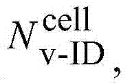

在另一实施例中,UE1被配置为接收UE特定地加扰的UE-RS,并且UE1被指令为使用RRC参数RRC_SCID来生成UE-RS加扰的初始化,其中RRC_SCID指示(
在另一实施例中,UE1被配置为接收UE特定地加扰的UE-RS,并且UE1被指令为使用RRC参数RRC_SCID来生成UE-RS加扰初始化,其中RRC_SCID指示

DL/UL授权DCI格式中的UE-RS加扰方法的动态指示Dynamic indication of UE-RS scrambling method in DL/UL grant DCI format
为了促进图10中所示的异构网络中的下行链路传输,可以执行下面的方法。In order to facilitate downlink transmission in the heterogeneous network shown in FIG. 10, the following method may be performed.
用DL授权DCI格式引入动态PHY信令,用于指示UE-RS加扰方法。在一个实施例中,新的N比特信息单元(IE)(例如,UE-RS加扰方法IE)被嵌入DL授权DCI格式(例如,DCI格式2B/2C)中,用于指示2N个候选UE-RS加扰方法中的UE-RS加扰方法。两个候选UE-RS加扰方法可以从Rel-10兼容的UE-RS加扰、TP特定的UE-RS加扰、和UE特定的UE-RS加扰中选择。通过在新的一比特IE中指示两个状态,网络(或enodeB)可以灵活地调度用于高级UE(例如,Rel-11UE)的传输。Introduce dynamic PHY signaling with DL grant DCI format to indicate UE-RS scrambling method. In one embodiment, a new N-bit information element (IE) (eg, UE-RS scrambling method IE) is embedded in a DL grant DCI format (eg, DCI format 2B/2C) to indicate 2N candidate UEs - A UE-RS scrambling method among RS scrambling methods. Two candidate UE-RS scrambling methods can be selected from Rel-10 compatible UE-RS scrambling, TP-specific UE-RS scrambling, and UE-specific UE-RS scrambling. By indicating both states in a new one-bit IE, the network (or enodeB) can flexibly schedule transmissions for advanced UEs (eg, Rel-11 UEs).
网络可以动态地改变高级UE(例如,Rel-11UE)或者与来自第一组UE的一个或者与来自第二组UE的一个的MU-MIMO配对。网络可以在用于高级UE(例如,Rel-11UE)的SU-MIMO和MU-MIMO之间动态地改变传输方案。网络可以在用于高级UE(例如,Rel-11UE)的单TP操作和CoMP调度之间动态地改变传输方案。The network may dynamically change the MU-MIMO pairing of advanced UEs (eg, Rel-11 UEs) either with one from the first set of UEs or with one from the second set of UEs. The network can dynamically change the transmission scheme between SU-MIMO and MU-MIMO for advanced UEs (eg, Rel-11 UEs). The network can dynamically change the transmission scheme between single-TP operation and CoMP scheduling for advanced UEs (eg, Rel-11 UEs).
当通过动态信令将TP特定的UE-RS加扰配置用于UE时,TP特定地加扰用于UE的UE-RS。在一个示例中,UE-RS加扰初始化cinit至少部分取决于RRC配置的TP ID来确定。在另一示例中,UE-RS加扰初始化cinit至少部分取决于通过RRC信令配置的CSI-RS配置(resourceConfig、subframeConfig、antennaPortCount)来确定。When TP-specific UE-RS scrambling is configured for the UE through dynamic signaling, the TP-specific scrambling is for the UE-RS of the UE. In one example, UE-RS scrambling initialization c init is determined depending at least in part on the RRC configured TP ID. In another example, UE-RS scrambling initialization c init is determined depending at least in part on the CSI-RS configuration (resourceConfig, subframeConfig, antennaPortCount) configured through RRC signaling.
当通过动态信令将UE特定的UE-RS加扰配置用于UE时,UE特定地加扰用于UE的UE-RS。例如,UE-RS加扰初始化cinit至少部分取决于配置到UE的用于UE-RS加扰初始化的新的RRc参数来确定。When UE-specific UE-RS scrambling is configured for the UE through dynamic signaling, UE-specific scrambling of the UE-RS for the UE. For example, UE-RS scrambling initialization c init is determined depending at least in part on new RRc parameters configured to the UE for UE-RS scrambling initialization.
注意到UE特定的UE-RS加扰分配比TP特定的UE-RS加扰更灵活,因为可以配置用于UE-RS加扰的新的RRC参数来生成与UE-RS加扰初始化c′init一样的UE-RS加扰初始化cinit,取决于TP特定的参数,例如,RRC配置的TP ID或CSI-RS配置来确定UE-RS加扰初始化c′init。还注意到UE特定的加扰比TP特定的加扰需要更多的开销,即,更多的RRC信令,因为TP特定的加扰可以使用已经可用的TP特定的参数来实施。Note that UE-specific UE-RS scrambling allocation is more flexible than TP-specific UE-RS scrambling, since new RRC parameters for UE-RS scrambling can be configured to generate the same UE-RS scrambling initialization c′ init The same UE-RS scrambling initialization c init depends on TP-specific parameters, for example, RRC configured TP ID or CSI-RS configuration to determine UE-RS scrambling initialization c′ init . Note also that UE-specific scrambling requires more overhead, ie more RRC signaling, than TP-specific scrambling, since TP-specific scrambling can be implemented using already available TP-specific parameters.
DL授权DCI格式结构示例DL authorized DCI format structure example
新的DL授权DCI格式可以通过延长现有的DL授权DCI格式(例如,DCI格式2B/2C)来包括新引入的UE-RS加扰方法IE来构建。A new DL grant DCI format can be constructed by extending an existing DL grant DCI format (eg, DCI format 2B/2C) to include a newly introduced UE-RS scrambling method IE.
在一个示例中,新的DL授权DCI格式通过向现有的DCI格式添加用于N比特UE-RS加扰IE的N比特来构建。在另一示例中,通过重新解释(或代替)SC-ID比特和添加UE-RS加扰方法IE所需的另外的比特来构建新的DL授权DCI格式。在又一示例中,通过重新解释(或代替)SC-ID码点和添加UE-RS加扰方法IE所需的另外的比特来构建新的DL授权DCI格式。对于本领域技术人员应该显然的是,即使当SC-ID字段被重新解释时,nSCID值仍然可以根据SC-ID码点来确定。例如,在DCI格式2B中,nSCID可以是0或1,并且根据表6.10.3.1-1通过加扰标识字段来提供。In one example, a new DL grant DCI format is constructed by adding N bits for an N-bit UE-RS scrambling IE to an existing DCI format. In another example, a new DL grant DCI format is constructed by reinterpreting (or replacing) the SC-ID bits and adding additional bits required by the UE-RS Scrambling Method IE. In yet another example, a new DL grant DCI format is constructed by reinterpreting (or replacing) the SC-ID code point and adding additional bits required by the UE-RS Scrambling Method IE. It should be apparent to those skilled in the art that even when the SC-ID field is reinterpreted, the n SCID value can still be determined from the SC-ID code point. For example, in DCI format 2B, nSCID can be 0 or 1 and is provided by scrambling the identification field according to Table 6.10.3.1-1.
现在参照图11和图12来说明嵌入新引入的UE-RS加扰方法IE的延长DCI格式2B的许多示例DCI格式布置。A number of example DCI format arrangements for Extended DCI Format 2B embedding the newly introduced UE-RS Scrambling Method IE are now illustrated with reference to FIGS. 11 and 12 .
在一个实施例中,新的一比特信息单元(IE),UE-RS加扰方法IE,被嵌入到DL授权DCI格式2B中,用于指示两个候选UE-RS加扰方法中的UE-RS加扰方法。下面描述用于将新的一位IE嵌入在新的DL授权DCI格式中的两种示例方法。In one embodiment, a new one-bit information element (IE), UE-RS scrambling method IE, is embedded in DL grant DCI format 2B to indicate the UE-RS scrambling method among two candidate UE-RS scrambling methods. RS scrambling method. Two example methods for embedding the new one-bit IE in the new DL grant DCI format are described below.
在第一示例方法中,新的DCI格式(在图11中通过DCI格式2B-1来表示)通过向DCI格式2B添加1比特来定义,其中新添加的比特用于指示UE-RS加扰方法的UE-RS加扰方法IE。在第二示例方法中,新的DCI格式(在图11中通过DCI格式2B-2来表示)与传统的DCI格式(例如,DCI格式2B)一样,除了一比特字段,例如,SC-ID比特的解释。在新的DCI格式中,SC-ID比特被重新解释为指示UE-RS加扰方法的UE-RS加扰方法IE(或者用其代替)。In a first example method, a new DCI format (represented by DCI format 2B-1 in FIG. 11 ) is defined by adding 1 bit to DCI format 2B, where the newly added bit is used to indicate the UE-RS scrambling method UE-RS Scrambling Method IE. In a second example approach, the new DCI format (represented by DCI format 2B-2 in FIG. 11 ) is the same as the legacy DCI format (e.g., DCI format 2B), except for a one-bit field, e.g., the SC-ID bit explanation of. In the new DCI format, the SC-ID bit is reinterpreted as (or replaced by) the UE-RS Scrambling Method IE indicating the UE-RS scrambling method.
在一个实施例中,新的两比特信息单元(IE),UE-RS加扰方法IE,被嵌入在DL授权DCI格式2B中,用于指示四个候选UE-RS加扰方法中的UE-RS加扰方法。下面描述用于将新的两比特IE嵌入在新的DL授权DCI格式中的两种示例方法。In one embodiment, a new two-bit information element (IE), UE-RS Scrambling Method IE, is embedded in DL Grant DCI Format 2B to indicate UE-RS scrambling method among four candidate UE-RS scrambling methods RS scrambling method. Two example methods for embedding the new two-bit IE in the new DL grant DCI format are described below.
在第一示例方法中,新的DCI格式(在图12中通过DCI格式2B-3来表示)通过向DCI格式2B添加两比特来定义,其中新添加的比特用于指示UE-RS加扰方法的UE-RS加扰方法IE。在第二示例方法中,新的DCI格式(在图12中通过DCI格式2B-4来表示)与传统的DCI格式(例如,DCI格式2B)一样,除了移除一比特字段,例如,SC-ID比特。在新的DCI格式中,SC-ID比特被重新解释为指示UE-RS加扰方法的两比特UE-RS加扰方法IE(或者用其代替)。In a first example method, a new DCI format (represented by DCI format 2B-3 in Figure 12) is defined by adding two bits to DCI format 2B, where the newly added bits are used to indicate the UE-RS scrambling method UE-RS Scrambling Method IE. In a second example method, the new DCI format (represented by DCI format 2B-4 in FIG. ID bits. In the new DCI format, the SC-ID bit is reinterpreted as (or replaced by) a two-bit UE-RS Scrambling Method IE indicating the UE-RS scrambling method.
UE-RS加扰方法IE示例UE-RS scrambling method IE example
参照下面的表12、表13、表14、表15、表16和表17来说明N比特UE-RS加扰方法IE的许多示例布置。A number of example arrangements of the N-bit UE-RS Scrambling Method IE are illustrated with reference to Table 12, Table 13, Table 14, Table 15, Table 16 and Table 17 below.
在一个实施例中,在表12中定义的新的一比特信息单元(IE),UE-RS扰码方法IE,被嵌入在DL授权DCI格式(例如,DCI格式2B/2C)中,用于指示两个候选UE-RS加扰方法:Rel-10兼容的(小区特定的)UE-RS加扰和TP特定的UE-RS加扰中的UE-RS加扰方法。In one embodiment, a new one-bit information element (IE) defined in Table 12, UE-RS Scrambling Method IE, is embedded in a DL grant DCI format (e.g., DCI format 2B/2C) for Two candidate UE-RS scrambling methods are indicated: UE-RS scrambling methods in Rel-10 compatible (cell-specific) UE-RS scrambling and TP-specific UE-RS scrambling.
表12UE-RS加扰方法的动态指示(示例1)Table 12 Dynamic indication of UE-RS scrambling method (Example 1)
存在很多方法用于实施TP特定的UE-RS加扰。例如,加扰初始化cinit至少部分通过RRC配置的TP-ID来确定。作为另一示例,加扰初始化cinit至少部分通过CSI-RS配置中的resourceConfig、subframeConfig和antennaPortCount中的至少一个来确定。There are many methods for implementing TP specific UE-RS scrambling. For example, the scrambling initialization c init is determined at least in part by the RRC configured TP-ID. As another example, the scrambling initialization c init is at least partially determined by at least one of resourceConfig, subframeConfig and antennaPortCount in the CSI-RS configuration.
根据如在表12中定义的一比特UE-RS加扰方法IE,网络可以通过如在下面的场景中设置新的一比特IE来执行图10中所示的下行链路传输。According to the one-bit UE-RS scrambling method IE as defined in Table 12, the network can perform the downlink transmission shown in FIG. 10 by setting a new one-bit IE as in the following scenario.
在一个场景中,UE4和UE5两者都被配置有子帧n中的一比特IE=1,即,TP特定的UE-RS加扰。UE4与RRH1关联,并且UE5与RRH2关联。因为UE4的位置接近RRH1而UE5的位置接近RRH2(其位置远离RRH1),所以网络可以在子帧中调度相同的PRB用于UE4和UE5而不着重考虑干扰功率。TP特定的UE-RS加扰确保在接收器处来自RRH1和RRH2的两个UE-RS不会相干合并。In one scenario, both UE4 and UE5 are configured with one-bit IE=1 in subframe n, ie, TP-specific UE-RS scrambling. UE4 is associated with RRH1 and UE5 is associated with RRH2. Since UE4 is located close to RRH1 and UE5 is located close to RRH2 (its location is far away from RRH1), the network can schedule the same PRB in a subframe for UE4 and UE5 without focusing on the interference power. TP-specific UE-RS scrambling ensures that the two UE-RSs from RRH1 and RRH2 are not coherently combined at the receiver.
在另一场景中,UE1被配置有子帧n中的一比特IE=0,即,Rel-10兼容的UE-RS加扰。Rel-11UE1和Rel-10UE0可以在相同的PRB中MU-MIMO复用并且它们的UE-RS可以正交复用,而不影响Rel-10UE0的解调性能。In another scenario, UE1 is configured with one-bit IE=0 in subframe n, ie Rel-10 compatible UE-RS scrambling. Rel-11UE1 and Rel-10UE0 can be MU-MIMO multiplexed in the same PRB and their UE-RSs can be orthogonally multiplexed without affecting the demodulation performance of Rel-10UE0.
在又另一场景中,UE2和UE3两者都被配置有子帧n中的一比特IE=1,即,TP特定的UE-RS加扰。UE2和UE3与宏关联。只要两个Rel-11UE与相同的TP(在此情况中是宏)关联,两个Rel-11UE的UE-RS就可以正交复用用于MU-MIMO操作。In yet another scenario, both UE2 and UE3 are configured with one-bit IE=1 in subframe n, ie, TP-specific UE-RS scrambling. UE2 and UE3 are associated with macros. As long as the two Rel-11 UEs are associated with the same TP (macro in this case), the UE-RS of two Rel-11 UEs can be orthogonally multiplexed for MU-MIMO operation.
在又另一场景中,UE3被配置有子帧n+1中的一比特IE=0,即,Rel-10兼容的UE-RS加扰。Rel-11UE3和Rel-10UE0可以在相同的PRB中MU-MIMO复用并且它们的UE-RS可以正交复用,而不影响Rel-10UE0的解调性能。In yet another scenario, UE3 is configured with one-bit IE=0 in subframe n+1, ie Rel-10 compatible UE-RS scrambling. Rel-11UE3 and Rel-10UE0 can be MU-MIMO multiplexed in the same PRB and their UE-RSs can be orthogonally multiplexed without affecting the demodulation performance of Rel-10UE0.
在另一个实施例中,在表13中定义的新的一比特信息单元(IE),UE-RS加扰方法IE,被嵌入在DL授权DCI格式(例如,DCI格式2B/2C)中,用于指示两个候选UE-RS加扰方法:Rel-10兼容的(小区特定的)UE-RS加扰和TP特定的UE-RS加扰中的UE-RS加扰方法。In another embodiment, a new one-bit information element (IE) defined in Table 13, UE-RS Scrambling Method IE, is embedded in a DL grant DCI format (e.g., DCI format 2B/2C) with Indicates two candidate UE-RS scrambling methods: Rel-10 compatible (cell-specific) UE-RS scrambling and UE-RS scrambling methods in TP-specific UE-RS scrambling.
表13UE-RS加扰方法的动态指示(示例2)Table 13 Dynamic indication of UE-RS scrambling method (Example 2)

存在很多方法用于实施UE特定的UE-RS加扰。例如,加扰初始化cinit至少部分通过用于UE-RS加扰初始化的新的RRC配置的参数来确定。There are many methods for implementing UE-specific UE-RS scrambling. For example, scrambling initialization c init is determined at least in part by parameters of a new RRC configuration for UE-RS scrambling initialization.
根据如在表13中定义的一比特UE-RS加扰方法IE,网络可以通过如在下面的场景中设置新的一比特IE并配置新的RRC参数来执行下行链路传输。According to the one-bit UE-RS scrambling method IE as defined in Table 13, the network can perform downlink transmission by setting a new one-bit IE and configuring new RRC parameters as in the following scenario.
在一个场景中,UE4和UE5两者都被配置有子帧n中的一比特IE=1,即,UE特定的UE-RS加扰。网络分配不同的RRC UE-RS加扰初始化参数用于UE4和UE5,使得用于UE4和UE5的两个UE-RS在接收器处不相干合并,或者两个加扰初始化参数不相同。UE4与RRH1关联,并且UE5与RRH2关联。因为UE4的位置接近RRH1而UE5的位置接近RRH2(其位置远离RRH1),所以网络可以在子帧中调度相同的PRB用于UE4和UE5而不着重考虑干扰功率。UE特定的UE-RS加扰确保在接收器处来自RRH1和RRH2的两个UE-RS不会相干合并。In one scenario, both UE4 and UE5 are configured with one-bit IE=1 in subframe n, ie UE-specific UE-RS scrambling. The network assigns different RRC UE-RS scrambling initialization parameters for UE4 and UE5 such that the two UE-RSs for UE4 and UE5 are combined non-coherently at the receiver, or the two scrambling initialization parameters are not the same. UE4 is associated with RRH1 and UE5 is associated with RRH2. Since UE4 is located close to RRH1 and UE5 is located close to RRH2 (its location is far away from RRH1), the network can schedule the same PRB in a subframe for UE4 and UE5 without focusing on the interference power. UE-specific UE-RS scrambling ensures that the two UE-RSs from RRH1 and RRH2 are not coherently combined at the receiver.
在另一场景中,UE1被配置有子帧n中的一比特IE=0,即,Rel-10兼容的UE-RS加扰。Rel-11UE1和Rel-10UE0可以在相同的PRB中MU-MIMO复用并且它们的UE-RS可以正交复用,而不影响Rel-10UE0的解调性能。In another scenario, UE1 is configured with one-bit IE=0 in subframe n, ie Rel-10 compatible UE-RS scrambling. Rel-11UE1 and Rel-10UE0 can be MU-MIMO multiplexed in the same PRB and their UE-RSs can be orthogonally multiplexed without affecting the demodulation performance of Rel-10UE0.
在又另一场景中,UE2和UE3两者都被配置有子帧n中的一比特IE=1,即,UE特定的UE-RS加扰。网络分配相同的RRC UE-RS加扰初始化参数用于UE2和UE3,使得用于UE2和UE3的两个UE-RS可以正交复用,或者两个加扰初始化参数相同。两个Rel-11UE的UE-RS可以正交复用用于MU-MIMO操作。In yet another scenario, both UE2 and UE3 are configured with one-bit IE=1 in subframe n, ie UE-specific UE-RS scrambling. The network allocates the same RRC UE-RS scrambling initialization parameters for UE2 and UE3, so that the two UE-RSs for UE2 and UE3 can be orthogonally multiplexed, or the two scrambling initialization parameters are the same. UE-RSs of two Rel-11 UEs can be multiplexed orthogonally for MU-MIMO operation.
在又另一场景中,UE3被配置有子帧n+1中的一比特IE=0,即,Rel-10兼容的UE-RS加扰。Rel-11UE3和Rel-10UE0可以在相同的PRB中MU-MIMO复用并且它们的UE-RS可以正交复用,而不影响Rel-10UE0的解调性能。In yet another scenario, UE3 is configured with one-bit IE=0 in subframe n+1, ie Rel-10 compatible UE-RS scrambling. Rel-11UE3 and Rel-10UE0 can be MU-MIMO multiplexed in the same PRB and their UE-RSs can be orthogonally multiplexed without affecting the demodulation performance of Rel-10UE0.
在另一实施例中,在表14中定义的新的一比特信息单元(IE),UE-RS加扰方法IE,被嵌入在DL授权DCI格式(例如,DCI格式2B/2C)中,用于指示两个候选UE-RS加扰方法:UE特定的UE-RS加扰和TP特定的UE-RS加扰中的UE-RS加扰方法。In another embodiment, a new one-bit information element (IE) defined in Table 14, UE-RS Scrambling Method IE, is embedded in a DL grant DCI format (e.g., DCI format 2B/2C) with Indicates two candidate UE-RS scrambling methods: UE-specific UE-RS scrambling and UE-RS scrambling methods in TP-specific UE-RS scrambling.
表14UE-RS加扰方法的动态指示(示例3)Table 14 Dynamic indication of UE-RS scrambling method (Example 3)
存在很多方法用于实施TP特定的UE-RS加扰。例如,加扰初始化cinit至少部分通过RRC配置的TP-ID来确定。作为另一示例,加扰初始化cinit至少部分通过CSI-RS配置中的resourceConfig、subframeConfig和antennaPortCount中的至少一个来确定。There are many methods for implementing TP specific UE-RS scrambling. For example, the scrambling initialization c init is determined at least in part by the RRC configured TP-ID. As another example, the scrambling initialization c init is at least partially determined by at least one of resourceConfig, subframeConfig and antennaPortCount in the CSI-RS configuration.
存在很多方法用于实施UE特定的UE-RS加扰。例如,加扰初始化cinit至少部分通过用于UE-RS加扰初始化的新的RRC配置的参数来确定。There are many methods for implementing UE-specific UE-RS scrambling. For example, scrambling initialization c init is determined at least in part by parameters of a new RRC configuration for UE-RS scrambling initialization.
根据如在表14中定义的一比特UE-RS加扰方法IE,网络可以通过如在下面的场景中设置新的一比特IE并配置新的RRC参数来执行图10所示的下行链路传输。According to the one-bit UE-RS scrambling method IE as defined in Table 14, the network can perform the downlink transmission shown in Figure 10 by setting a new one-bit IE and configuring new RRC parameters as in the following scenarios .
在一个场景中,UE4和UE5两者都被配置有子帧n中的一比特IE=1,即,TP特定的UE-RS加扰。UE4与RRH1关联,并且UE5与RRH2关联。因为UE4的位置接近RRH1而UE5的位置接近RRH2(其位置远离RRH1),所以网络可以在子帧中调度相同的PRB用于UE4和UE5而不着重考虑干扰功率。TP特定的UE-RS加扰确保在接收器处来自RRH1和RRH2的两个UE-RS不会相干合并。In one scenario, both UE4 and UE5 are configured with one-bit IE=1 in subframe n, ie, TP-specific UE-RS scrambling. UE4 is associated with RRH1 and UE5 is associated with RRH2. Since UE4 is located close to RRH1 and UE5 is located close to RRH2 (its location is far away from RRH1), the network can schedule the same PRB in a subframe for UE4 and UE5 without focusing on the interference power. TP-specific UE-RS scrambling ensures that the two UE-RSs from RRH1 and RRH2 are not coherently combined at the receiver.
在另一场景中,UE1被配置有子帧n中的一比特IE=0,即,UE特定的UE-RS加扰。用于UE-RS加扰初始化的新的RRC参数被配置为生成与Rel-10UE-RS一样的UE特定的UE-RS加扰初始化。Rel-11UE1和Rel-10UE0可以在相同的PRB中MU-MIMO复用并且它们的UE-RS可以正交复用,而不影响Rel-10UE0的解调性能。In another scenario, UE1 is configured with one-bit IE=0 in subframe n, ie UE-specific UE-RS scrambling. New RRC parameters for UE-RS scrambling initialization are configured to generate UE-specific UE-RS scrambling initialization like Rel-10 UE-RS. Rel-11UE1 and Rel-10UE0 can be MU-MIMO multiplexed in the same PRB and their UE-RSs can be orthogonally multiplexed without affecting the demodulation performance of Rel-10UE0.
在又另一场景中,UE2和UE3两者都被配置有子帧n中的一比特IE=1,即,TP特定的UE-RS加扰。只要两个Rel-11UE与相同的TP(在此情况中是宏)关联,两个UE的UE-RS就可以正交复用用于MU-MIMO操作。In yet another scenario, both UE2 and UE3 are configured with one-bit IE=1 in subframe n, ie, TP-specific UE-RS scrambling. As long as the two Rel-11 UEs are associated with the same TP (macro in this case), the UE-RS of the two UEs can be orthogonally multiplexed for MU-MIMO operation.
在又另一场景中,UE3被配置有子帧n+1中的一比特IE=0,即,UE特定的UE-RS加扰。用于UE-RS加扰初始化的新的RRC参数被配置为生成与Rel-10UE-RS一样的UE特定的UE-RS加扰初始化。Rel-11UE3和Rel-10UE0可以在相同的PRB中MU-MIMO复用并且它们的UE-RS可以正交复用,而不影响Rel-10UE0的解调性能。In yet another scenario, UE3 is configured with one bit IE=0 in subframe n+1, ie UE-specific UE-RS scrambling. New RRC parameters for UE-RS scrambling initialization are configured to generate UE-specific UE-RS scrambling initialization like Rel-10 UE-RS. Rel-11UE3 and Rel-10UE0 can be MU-MIMO multiplexed in the same PRB and their UE-RSs can be orthogonally multiplexed without affecting the demodulation performance of Rel-10UE0.
在另一实施例中,在表15中定义的新的一比特信息单元(IE),UE-RS加扰方法IE,被嵌入在DL授权DCI格式(例如,DCI格式2B/2C)中,用于指示两个候选UE-RS加扰方法:根据第一加扰初始化cinit,0的UE特定的UE-RS加扰,和根据第二加扰初始化cinit,1的UE特定的UE-RS加扰中的UE-RS加扰方法。In another embodiment, a new one-bit information element (IE) defined in Table 15, UE-RS Scrambling Method IE, is embedded in a DL grant DCI format (e.g., DCI format 2B/2C) with to indicate two candidate UE-RS scrambling methods: UE-specific UE-RS scrambling according to the first scrambling initialization c init,0 , and UE-specific UE-RS scrambling according to the second scrambling initialization c init,1 UE-RS scrambling method in scrambling.
表15UE-RS加扰方法的动态指示(示例4)TABLE 15 Dynamic indication of UE-RS scrambling method (Example 4)
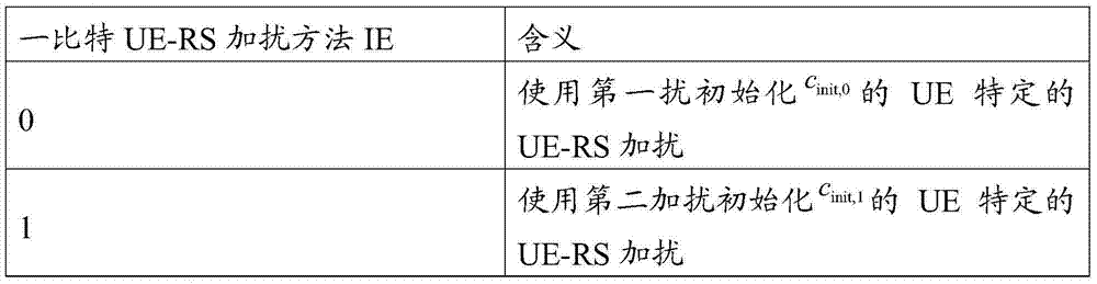
这里,cinit,0至少部分在用于UE-RS加扰初始化的第一新的RRC配置的参数,例如,RRC_SCID0上确定。同样地,cinit,1至少部分在用于UE-RS加扰初始化的第二新的RRC配置的参数,例如,RRC_SCID1上确定。Here, c init,0 is at least partly determined on the parameters of the first new RRC configuration for UE-RS scrambling initialization, eg, RRC_SCID0. Likewise, c init,1 is determined at least in part on the parameters of the second new RRC configuration for UE-RS scrambling initialization, eg, RRC_SCID1.
根据如在表15中定义的一比特UE-RS加扰方法IE,网络可以通过如在下面的场景中设置新的一比特IE并配置新的RRC参数来执行图10所示的下行链路传输。According to the one-bit UE-RS scrambling method IE as defined in Table 15, the network can perform the downlink transmission shown in Figure 10 by setting a new one-bit IE and configuring new RRC parameters as in the following scenario .
在一个场景中,UE4和UE5两者都被配置有子帧n中的一比特IE=0,即,第一UE特定的UE-RS加扰。网络分配不同的RRC_SCID0用于UE4和UE5,使得用于UE4和UE5的两个UE-RS在接收器处不相干合并,或者两个加扰初始化参数不相同。UE4与RRH1关联,并且UE5与RRH2关联。因为UE4的位置接近RRH1而UE5的位置接近RRH2(其位置远离RRH1),所以网络可以在子帧中调度相同的PRB用于UE4和UE5而不着重考虑干扰功率。UE特定的UE-RS加扰确保在接收器处来自RRH1和RRH2的两个UE-RS不会相干合并。In one scenario, both UE4 and UE5 are configured with one-bit IE=0 in subframe n, ie first UE-specific UE-RS scrambling. The network allocates different RRC_SCID0 for UE4 and UE5, so that the two UE-RSs for UE4 and UE5 are combined non-coherently at the receiver, or the two scrambling initialization parameters are not the same. UE4 is associated with RRH1 and UE5 is associated with RRH2. Since UE4 is located close to RRH1 and UE5 is located close to RRH2 (its location is far away from RRH1), the network can schedule the same PRB in a subframe for UE4 and UE5 without focusing on the interference power. UE-specific UE-RS scrambling ensures that the two UE-RSs from RRH1 and RRH2 are not coherently combined at the receiver.
在另一场景中,UE1被配置有子帧n中的一比特IE=1,即,第二UE特定的UE-RS加扰。这里,如此配置RRC_SCID1使得它生成与Rel-10UE-RS的一样的UE1的cinit,1。Rel-11UE1和Rel-10UE0可以在相同的PRB中MU-MIMO复用并且它们的UE-RS可以正交复用,而不影响Rel-10UE0的解调性能。In another scenario, UE1 is configured with one-bit IE=1 in subframe n, ie, second UE-specific UE-RS scrambling. Here, RRC_SCID1 is configured such that it generates c init,1 of UE1 the same as that of Rel-10 UE-RS. Rel-11UE1 and Rel-10UE0 can be MU-MIMO multiplexed in the same PRB and their UE-RSs can be orthogonally multiplexed without affecting the demodulation performance of Rel-10UE0.
在又另一场景中,UE2和UE3两者都被配置有子帧n中的一比特IE=0,即,第一UE特定的UE-RS加扰。网络分配相同的RRC_SCID0用于UE2和UE3,使得用于UE2和UE3的两个UE-RS可以被使得正交。两个Rel-11UE的UE-RS可以正交复用用于MU-MIMO操作。In yet another scenario, both UE2 and UE3 are configured with one-bit IE=0 in subframe n, ie, first UE-specific UE-RS scrambling. The network allocates the same RRC_SCID0 for UE2 and UE3 so that the two UE-RSs for UE2 and UE3 can be made orthogonal. UE-RSs of two Rel-11 UEs can be multiplexed orthogonally for MU-MIMO operation.
在又另一场景中,UE3被配置有子帧n+1中的一比特IE=1,即,第二UE特定的UE-RS加扰。这里,如此配置RRC_SCID1使得它生成与Rel-10UE-RS的一样的UE3的cinit,1。Rel-11UE3和Rel-10UE0可以在相同的PRB中MU-MIMO复用并且它们的UE-RS可以正交复用,而不影响Rel-10UE0的解调性能。In yet another scenario, UE3 is configured with one-bit IE=1 in subframe n+1, ie, second UE-specific UE-RS scrambling. Here, RRC_SCID1 is configured such that it generates c init,1 of UE3 the same as that of Rel-10 UE-RS. Rel-11UE3 and Rel-10UE0 can be MU-MIMO multiplexed in the same PRB and their UE-RSs can be orthogonally multiplexed without affecting the demodulation performance of Rel-10UE0.
在另一实施例中,在表16中定义的新的一比特信息单元(IE),UE-RS加扰方法IE,被嵌入在DL授权DCI格式(例如,DCI格式2B/2C)中,用于指示两个候选UE-RS加扰方法:具有固定的nSCID的Rel-10兼容的(小区特定的)UE-RS加扰和TP特定的UE-RS加扰中的UE-RS加扰方法。在一个示例中,nSCID被固定为0。在另一示例中,nSCID被固定为1。将nSCID设置为常数,可以节省一比特信令开销。因此,如在图11中的DCI格式2B-2和图12中的DCI格式2B-4中,通过从DCI格式2B中移除SC-ID比特并用UE-RS加扰方法IE代替它,可以布置新的DL授权DCI格式。In another embodiment, a new one-bit information element (IE) defined in Table 16, UE-RS Scrambling Method IE, is embedded in a DL grant DCI format (e.g., DCI format 2B/2C) with Indicates two candidate UE-RS scrambling methods: UE-RS scrambling methods in Rel-10 compatible (cell-specific) UE-RS scrambling with fixed n SCID and TP-specific UE-RS scrambling . In one example, n SCID is fixed at zero. In another example, n SCID is fixed at 1. Setting n SCID as a constant can save one bit of signaling overhead. Therefore, as in DCI format 2B-2 in FIG. 11 and DCI format 2B-4 in FIG. 12 , by removing the SC-ID bit from DCI format 2B and replacing it with UE-RS scrambling method IE, it is possible to arrange New DL authorized DCI format.
表16UE-RS加扰方法的动态指示(示例5)TABLE 16 Dynamic indication of UE-RS scrambling method (Example 5)
存在很多方法用于实施TP特定的UE-RS加扰。例如,加扰初始化cinit至少部分通过RRC配置的TP-ID来确定。作为另一示例,加扰初始化cinit至少部分通过CSI-RS配置中的resourceConfig、subframeConfig和antennaPortCount中的至少一个来确定。There are many methods for implementing TP specific UE-RS scrambling. For example, the scrambling initialization c init is determined at least in part by the RRC configured TP-ID. As another example, the scrambling initialization c init is at least partially determined by at least one of resourceConfig, subframeConfig and antennaPortCount in the CSI-RS configuration.
根据如在表16中定义的一比特UE-RS加扰方法IE,网络可以通过如在下面的场景中设置新的一比特IE来执行图10中所示的下行链路传输。According to the one-bit UE-RS scrambling method IE as defined in Table 16, the network can perform the downlink transmission shown in FIG. 10 by setting a new one-bit IE as in the following scenario.
在一个场景中,UE4和UE5两者都被配置有子帧n中的一比特IE=1,即,TP特定的UE-RS加扰。UE4与RRH1关联,并且UE5与RRH2关联。因为UE4的位置接近RRH1而UE5的位置接近RRH2(其位置远离RRH1),所以网络可以在子帧中调度相同的PRB用于UE4和UE5而不着重考虑干扰功率。TP特定的UE-RS加扰确保在接收器处来自RRH1和RRH2的两个UE-RS不会相干合并。In one scenario, both UE4 and UE5 are configured with one-bit IE=1 in subframe n, ie, TP-specific UE-RS scrambling. UE4 is associated with RRH1 and UE5 is associated with RRH2. Since UE4 is located close to RRH1 and UE5 is located close to RRH2 (its location is far away from RRH1), the network can schedule the same PRB in a subframe for UE4 and UE5 without focusing on the interference power. TP-specific UE-RS scrambling ensures that the two UE-RSs from RRH1 and RRH2 are not coherently combined at the receiver.
在另一场景中,UE1被配置有子帧n中的一比特IE=0,即,Rel-10兼容的UE-RS加扰。Rel-11UE1和Rel-10UE0可以在相同的PRB中MU-MIMO复用并且它们的UE-RS可以正交复用,而不影响Rel-10UE0的解调性能。In another scenario, UE1 is configured with one-bit IE=0 in subframe n, ie Rel-10 compatible UE-RS scrambling. Rel-11UE1 and Rel-10UE0 can be MU-MIMO multiplexed in the same PRB and their UE-RSs can be orthogonally multiplexed without affecting the demodulation performance of Rel-10UE0.
在又另一场景中,UE2和UE3两者都被配置有子帧n中的一比特IE=1,即,TP特定的UE-RS加扰。UE2和UE3与宏关联。只要两个Rel-11UE与相同的TP(在此情况中是宏)关联,两个Rel-11UE的UE-RS就可以正交复用用于MU-MIMO操作。In yet another scenario, both UE2 and UE3 are configured with one-bit IE=1 in subframe n, ie, TP-specific UE-RS scrambling. UE2 and UE3 are associated with macros. As long as the two Rel-11 UEs are associated with the same TP (macro in this case), the UE-RS of two Rel-11 UEs can be orthogonally multiplexed for MU-MIMO operation.
在再一场景中,UE3被配置有子帧n+1中的一比特IE=0,即,Rel-10兼容的UE-RS加扰。Rel-11UE3和Rel-10UE0可以在相同的PRB中MU-MIMO复用并且它们的UE-RS可以正交复用,而不影响Rel-10UE0的解调性能。In yet another scenario, UE3 is configured with one-bit IE=0 in subframe n+1, ie, Rel-10 compatible UE-RS scrambling. Rel-11UE3 and Rel-10UE0 can be MU-MIMO multiplexed in the same PRB and their UE-RSs can be orthogonally multiplexed without affecting the demodulation performance of Rel-10UE0.
在另一实施例中,在表17中定义的新的一比特信息单元(IE),UE-RS加扰方法IE,被嵌入在DL授权DCI格式(例如,DCI格式2B/2C)中,用于指示两种候选UE-RS加扰方法:具有固定nSCID的Rel-10兼容的(小区特定的)UE-RS加扰与UE特定的UE-RS加扰中的UE-RS加扰方法。在一个示例中,nSCID被固定为0。在另一示例中,nSCID被固定为1。将nSCID设置为常数,可以节省一比特信令开销。因此,如在图11中的DCI格式2B-2和图12中的DCI格式2B-4中,通过从DCI格式2B中移除SC-ID比特并用UE-RS加扰方法IE代替它,可以布置新的DL授权DCI格式。In another embodiment, a new one-bit information element (IE) defined in Table 17, UE-RS Scrambling Method IE, is embedded in a DL grant DCI format (e.g., DCI format 2B/2C) with Indicates two candidate UE-RS scrambling methods: Rel-10 compatible (cell-specific) UE-RS scrambling with fixed n SCID and UE-RS scrambling methods in UE-specific UE-RS scrambling. In one example, n SCID is fixed at zero. In another example, n SCID is fixed at 1. Setting n SCID as a constant can save one bit of signaling overhead. Therefore, as in DCI format 2B-2 in FIG. 11 and DCI format 2B-4 in FIG. 12 , by removing the SC-ID bit from DCI format 2B and replacing it with UE-RS scrambling method IE, it is possible to arrange New DL authorized DCI format.
表17UE-RS加扰方法的动态指示(示例6)TABLE 17 Dynamic indication of UE-RS scrambling method (Example 6)
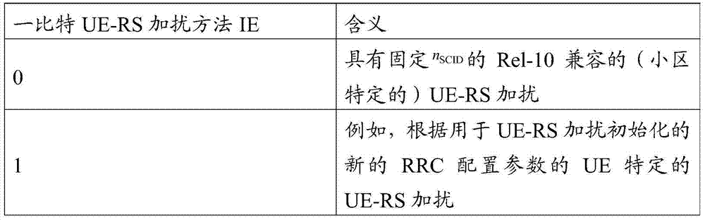
存在很多方法用于实施UE特定的UE-RS加扰。例如,加扰初始化cinit至少部分通过用于UE-RS加扰初始化的新的RRC配置的参数来确定。There are many methods for implementing UE-specific UE-RS scrambling. For example, scrambling initialization c init is determined at least in part by parameters of a new RRC configuration for UE-RS scrambling initialization.
根据如在表17中定义的一比特UE-RS加扰方法IE,网络可以通过如在下面的场景中设置新的一比特IE并配置新的RRC参数来执行图10中所示的下行链路传输。According to the one-bit UE-RS Scrambling Method IE as defined in Table 17, the network can perform the downlink shown in Figure 10 by setting a new one-bit IE and configuring new RRC parameters as in the following scenario transmission.
在一个场景中,UE4和UE5两者都被配置有子帧n中的一比特IE=1,即,UE特定的UE-RS加扰。网络分配不同的RRC UE-RS加扰初始化参数用于UE4和UE5,使得用于UE4和UE5的两个UE-RS在接收器处不相干合并,或者两个加扰初始化参数不相同。UE4与RRH1关联,并且UE5与RRH2关联。因为UE4的位置接近RRH1而UE5的位置接近RRH2(其位置远离RRH1),所以网络可以在子帧中调度相同的PRB用于UE4和UE5而不着重考虑干扰功率。UE特定的UE-RS加扰确保在接收器处来自RRH1和RRH2的两个UE-RS不会相干合并。In one scenario, both UE4 and UE5 are configured with one-bit IE=1 in subframe n, ie UE-specific UE-RS scrambling. The network assigns different RRC UE-RS scrambling initialization parameters for UE4 and UE5 such that the two UE-RSs for UE4 and UE5 are combined non-coherently at the receiver, or the two scrambling initialization parameters are not the same. UE4 is associated with RRH1 and UE5 is associated with RRH2. Since UE4 is located close to RRH1 and UE5 is located close to RRH2 (its location is far away from RRH1), the network can schedule the same PRB in a subframe for UE4 and UE5 without focusing on the interference power. UE-specific UE-RS scrambling ensures that the two UE-RSs from RRH1 and RRH2 are not coherently combined at the receiver.
在另一场景中,UE1被配置有子帧n中的一比特IE=0,即,Rel-10兼容的UE-RS加扰。Rel-11UE1和Rel-10UE0可以在相同的PRB中MU-MIMO复用并且它们的UE-RS可以正交复用,而不影响Rel-10UE0的解调性能。In another scenario, UE1 is configured with one-bit IE=0 in subframe n, ie Rel-10 compatible UE-RS scrambling. Rel-11UE1 and Rel-10UE0 can be MU-MIMO multiplexed in the same PRB and their UE-RSs can be orthogonally multiplexed without affecting the demodulation performance of Rel-10UE0.
在又另一场景中,UE2和UE3两者都被配置有子帧n中的一比特IE=1,即,UE特定的UE-RS加扰。网络分配相同的RRC UE-RS加扰初始化参数用于UE2和UE3,使得用于UE2和UE3的两个UE-RS可以正交复用,或者两个加扰初始化参数相同。两个Rel-11UE的UE-RS可以正交复用用于MU-MIMO操作。In yet another scenario, both UE2 and UE3 are configured with one-bit IE=1 in subframe n, ie UE-specific UE-RS scrambling. The network allocates the same RRC UE-RS scrambling initialization parameters for UE2 and UE3, so that the two UE-RSs for UE2 and UE3 can be orthogonally multiplexed, or the two scrambling initialization parameters are the same. UE-RSs of two Rel-11 UEs can be multiplexed orthogonally for MU-MIMO operation.
在又另一场景中,UE3被配置有子帧n+1中的一比特IE=0,即,Rel-10兼容的UE-RS加扰。Rel-11UE3和Rel-10UE0可以在相同的PRB中MU-MIMO复用并且它们的UE-RS可以正交复用,而不影响Rel-10UE0的解调性能。In yet another scenario, UE3 is configured with one-bit IE=0 in subframe n+1, ie Rel-10 compatible UE-RS scrambling. Rel-11UE3 and Rel-10UE0 can be MU-MIMO multiplexed in the same PRB and their UE-RSs can be orthogonally multiplexed without affecting the demodulation performance of Rel-10UE0.
在另一个实施例中,新的两比特信息单元(IE),或在表18中定义的UE-RS加扰方法IE,被嵌入在DL授权DCI格式(例如,DCI格式2B/2C)中,用于指示三个候选UE-RS加扰方法:Rel-10兼容的(小区特定的)UE-RS加扰、UE特定的UE-RS加扰、和TP特定的UE-RS加扰中的UE-RS加扰方法。在UE-RS加扰方法IE中拥有多一个状态,网络可以执行更灵活的UE调度/配对。In another embodiment, a new two-bit information element (IE), or the UE-RS scrambling method IE defined in Table 18, is embedded in the DL grant DCI format (e.g., DCI format 2B/2C), Used to indicate UE in three candidate UE-RS scrambling methods: Rel-10 compatible (cell-specific) UE-RS scrambling, UE-specific UE-RS scrambling, and TP-specific UE-RS scrambling - RS scrambling method. With one more state in the UE-RS Scrambling Method IE, the network can perform more flexible UE scheduling/pairing.
表18UE-RS加扰方法的动态指示(示例7)TABLE 18 Dynamic indication of UE-RS scrambling method (Example 7)
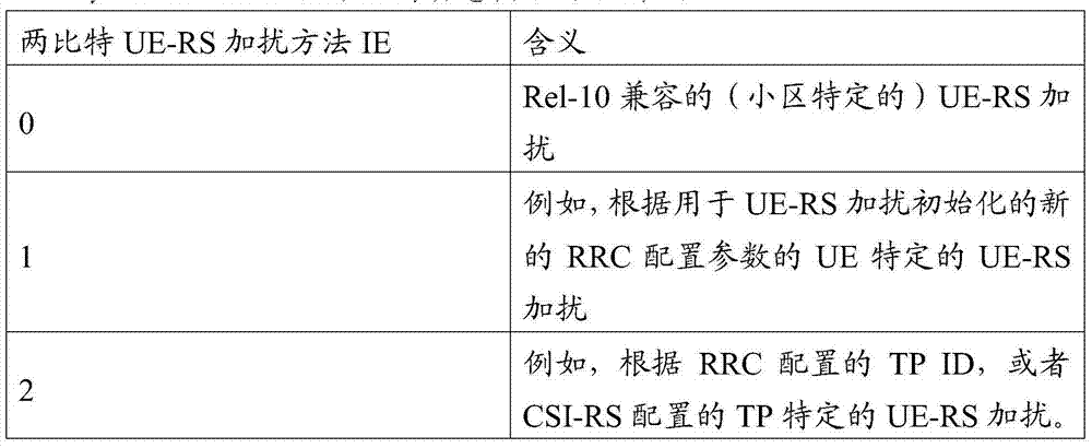
存在很多方法用于实施UE特定的UE-RS加扰。例如,加扰初始化cinit至少部分通过用于UE-RS加扰初始化的新的RRC配置的参数来确定。There are many methods for implementing UE-specific UE-RS scrambling. For example, scrambling initialization c init is determined at least in part by parameters of a new RRC configuration for UE-RS scrambling initialization.
存在很多方法用于实施TP特定的UE-RS加扰。例如,加扰初始化cinit至少部分通过RRC配置的TP-ID来确定。作为另一示例,加扰初始化cinit至少部分通过CSI-RS配置中的resourceConfig、subframeConfig、和antennaPortCount中的至少一个来确定。There are many methods for implementing TP specific UE-RS scrambling. For example, the scrambling initialization c init is determined at least in part by the RRC configured TP-ID. As another example, the scrambling initialization c init is determined at least in part by at least one of resourceConfig, subframeConfig, and antennaPortCount in the CSI-RS configuration.
根据如在表18中定义的两比特UE-RS加扰方法IE,网络可以通过如在下面的场景中设置新的两比特IE并配置新的RRC参数来执行图10中所示的下行链路传输。According to the two-bit UE-RS scrambling method IE as defined in Table 18, the network can perform the downlink shown in Figure 10 by setting a new two-bit IE and configuring new RRC parameters as in the following scenario transmission.
在一个场景中,UE4和UE5两者都被配置有子帧n中的两比特IE=2,即,TP特定的UE-RS加扰。UE4与RRH1关联,并且UE5与RRH2关联。因为UE4的位置接近RRH1而UE5的位置接近RRH2(其位置远离RRH1),所以网络可以在子帧中调度相同的PRB用于UE4和UE5而不着重考虑干扰功率。TP特定的UE-RS加扰确保在接收器处来自RRH1和RRH2的两个UE-RS不会相干合并。In one scenario, both UE4 and UE5 are configured with two-bit IE=2 in subframe n, ie, TP-specific UE-RS scrambling. UE4 is associated with RRH1 and UE5 is associated with RRH2. Since UE4 is located close to RRH1 and UE5 is located close to RRH2 (its location is far away from RRH1), the network can schedule the same PRB in a subframe for UE4 and UE5 without focusing on the interference power. TP-specific UE-RS scrambling ensures that the two UE-RSs from RRH1 and RRH2 are not coherently combined at the receiver.
在另一场景中,UE1被配置有子帧n中的两比特IE=0,即,Rel-10兼容的UE-RS加扰。Rel-11UE1和Rel-10UE0可以在相同的PRB中MU-MIMO复用并且它们的UE-RS可以正交复用,而不影响Rel-10UE0的解调性能。In another scenario, UE1 is configured with two bits of IE=0 in subframe n, ie Rel-10 compatible UE-RS scrambling. Rel-11UE1 and Rel-10UE0 can be MU-MIMO multiplexed in the same PRB and their UE-RSs can be orthogonally multiplexed without affecting the demodulation performance of Rel-10UE0.
在又另一场景中,UE2和UE3两者都被配置有子帧n中的两比特IE=1,即,UE特定的UE-RS加扰。网络分配相同的RRC UE-RS加扰初始化参数用于UE2和UE3,使得用于UE2和UE3的两个UE-RS可以正交复用,或者两个加扰初始化参数相同。两个Rel-11UE的UE-RS可以正交复用用于MU-MIMO操作。In yet another scenario, both UE2 and UE3 are configured with two bits of IE=1 in subframe n, ie UE-specific UE-RS scrambling. The network allocates the same RRC UE-RS scrambling initialization parameters for UE2 and UE3, so that the two UE-RSs for UE2 and UE3 can be orthogonally multiplexed, or the two scrambling initialization parameters are the same. UE-RSs of two Rel-11 UEs can be multiplexed orthogonally for MU-MIMO operation.
在又另一场景中,UE3被配置有子帧n+1中的两比特IE=0,即,Rel-10兼容的UE-RS加扰。Rel-11UE3和Rel-10UE0可以在相同的PRB中MU-MIMO复用并且它们的UE-RS可以正交复用,而不影响Rel-10UE0的解调性能。In yet another scenario, UE3 is configured with two-bit IE=0 in subframe n+1, ie Rel-10 compatible UE-RS scrambling. Rel-11UE3 and Rel-10UE0 can be MU-MIMO multiplexed in the same PRB and their UE-RSs can be orthogonally multiplexed without affecting the demodulation performance of Rel-10UE0.
在另一个实施例中,在表19中定义的新的两比特信息单元(IE),UE-RS加扰方法IE,被嵌入在DL授权DCI格式(例如,DCI格式2B/2C)中,用于指示三个候选UE-RS加扰方法:Rel-10兼容的(小区特定的)UE-RS加扰、UE特定的UE-RS加扰和TP特定的UE-RS加扰中的UE-RS加扰方法。在UE-RS加扰方法IE中拥有多一个状态,网络可以执行更灵活的UE调度/配对。在一个示例中,nSCID被固定为0。在另一示例中,nSCID被固定为1。将nSCID设置为常数,可以节省两比特的信令开销。因此,如在图11中的DCI格式2B-2和图12中的DCI格式2B-4中,通过从DCI格式2B中移除SC-ID比特并用UE-RS加扰方法IE代替它,可以布置新的DL授权DCI格式。In another embodiment, a new two-bit information element (IE) defined in Table 19, UE-RS Scrambling Method IE, is embedded in a DL grant DCI format (e.g., DCI format 2B/2C) with Indicates three candidate UE-RS scrambling methods: UE-RS in Rel-10 compatible (cell-specific) UE-RS scrambling, UE-specific UE-RS scrambling and TP-specific UE-RS scrambling Scrambling method. With one more state in the UE-RS Scrambling Method IE, the network can perform more flexible UE scheduling/pairing. In one example, n SCID is fixed at zero. In another example, n SCID is fixed at 1. Setting n SCID as a constant can save two bits of signaling overhead. Therefore, as in DCI format 2B-2 in FIG. 11 and DCI format 2B-4 in FIG. 12 , by removing the SC-ID bit from DCI format 2B and replacing it with UE-RS scrambling method IE, it is possible to arrange New DL authorized DCI format.
表19UE-RS加扰方法的动态指示(示例8)TABLE 19 Dynamic indication of UE-RS scrambling method (Example 8)

存在很多方法用于实施UE特定的UE-RS加扰。例如,加扰初始化cinit至少部分通过用于UE-RS加扰初始化的新的RRC配置的参数来确定。There are many methods for implementing UE-specific UE-RS scrambling. For example, scrambling initialization c init is determined at least in part by parameters of a new RRC configuration for UE-RS scrambling initialization.
存在很多方法用于实施TP特定的UE-RS加扰。例如,加扰初始化cinit至少部分通过RRC配置的TP-ID来确定。作为另一示例,加扰初始化cinit至少部分通过CSI-RS配置中的resourceConfig、subframeConfig和antennaPortCount中的至少一个来确定。There are many methods for implementing TP specific UE-RS scrambling. For example, the scrambling initialization c init is determined at least in part by the RRC configured TP-ID. As another example, the scrambling initialization c init is at least partially determined by at least one of resourceConfig, subframeConfig and antennaPortCount in the CSI-RS configuration.
根据如在表19中定义的两比特UE-RS加扰方法IE,网络可以通过如在下面的场景中设置新的两比特IE并配置新的RRC参数来执行图10中所示的下行链路传输。According to the two-bit UE-RS scrambling method IE as defined in Table 19, the network can perform the downlink shown in Figure 10 by setting a new two-bit IE and configuring new RRC parameters as in the following scenario transmission.
在一个场景中,UE4和UE5两者都被配置有子帧n中的两比特IE=2,即,TP特定的UE-RS加扰。UE4与RRH1关联,并且UE5与RRH2关联。因为UE4的位置接近RRH1而UE5的位置接近RRH2(其位置远离RRH1),所以网络可以在子帧中调度相同的PRB用于UE4和UE5而不着重考虑干扰功率。TP特定的UE-RS加扰确保在接收器处来自RRH1和RRH2的两个UE-RS不会相干合并。In one scenario, both UE4 and UE5 are configured with two-bit IE=2 in subframe n, ie, TP-specific UE-RS scrambling. UE4 is associated with RRH1 and UE5 is associated with RRH2. Since UE4 is located close to RRH1 and UE5 is located close to RRH2 (its location is far away from RRH1), the network can schedule the same PRB in a subframe for UE4 and UE5 without focusing on the interference power. TP-specific UE-RS scrambling ensures that the two UE-RSs from RRH1 and RRH2 are not coherently combined at the receiver.
在另一场景中,UE1被配置有子帧n中的两比特IE=0,即,Rel-10兼容的UE-RS加扰。Rel-11UE1和Rel-10UE0可以在相同的PRB中MU-MIMO复用并且它们的UE-RS可以正交复用,而不影响Rel-10UE0的解调性能。In another scenario, UE1 is configured with two bits of IE=0 in subframe n, ie Rel-10 compatible UE-RS scrambling. Rel-11UE1 and Rel-10UE0 can be MU-MIMO multiplexed in the same PRB and their UE-RSs can be orthogonally multiplexed without affecting the demodulation performance of Rel-10UE0.
在又另一场景中,UE2和UE3两者都被配置有子帧n中的两比特IE=1,即,UE特定的UE-RS加扰。网络分配相同的RRC UE-RS加扰初始化参数用于UE2和UE3,使得用于UE2和UE3的两个UE-RS可以正交复用,或者两个加扰初始化参数相同。两个Rel-11UE的UE-RS可以正交复用用于MU-MIMO操作。In yet another scenario, both UE2 and UE3 are configured with two bits of IE=1 in subframe n, ie UE-specific UE-RS scrambling. The network allocates the same RRC UE-RS scrambling initialization parameters for UE2 and UE3, so that the two UE-RSs for UE2 and UE3 can be orthogonally multiplexed, or the two scrambling initialization parameters are the same. UE-RSs of two Rel-11 UEs can be multiplexed orthogonally for MU-MIMO operation.
在又另一场景中,UE3被配置有子帧n+1中的两比特IE=0,即,Rel-10兼容的UE-RS加扰。Rel-11UE3和Rel-10UE0可以在相同的PRB中MU-MIMO复用并且它们的UE-RS可以正交复用,而不影响Rel-10UE0的解调性能。In yet another scenario, UE3 is configured with two-bit IE=0 in subframe n+1, ie Rel-10 compatible UE-RS scrambling. Rel-11UE3 and Rel-10UE0 can be MU-MIMO multiplexed in the same PRB and their UE-RSs can be orthogonally multiplexed without affecting the demodulation performance of Rel-10UE0.
在另一实施例中,在表20中定义的新的两比特信息单元(IE),UE-RS加扰方法IE,被嵌入在DL授权DCI格式(例如,DCI格式2B/2C)中,用于指示三种候选UE-RS加扰方法:根据第一加扰初始化,例如cinit,0的UE特定的UE-RS加扰,根据第二加扰初始化cinit,1的UE特定的UE-RS加扰,以及根据第二加扰初始化cinit,2的UE特定的UE-RS加扰中的UE-RS加扰方法。在UE-RS加扰方法IE中拥有多一个状态,网络可以执行更灵活的UE调度/配对。In another embodiment, a new two-bit information element (IE) defined in Table 20, UE-RS Scrambling Method IE, is embedded in a DL grant DCI format (e.g., DCI format 2B/2C) with to indicate three candidate UE-RS scrambling methods: UE-specific UE-RS scrambling according to the first scrambling initialization, e.g. c init,0 , UE-specific UE-RS scrambling according to the second scrambling initialization c init,1 RS scrambling, and a UE-RS scrambling method in UE-specific UE-RS scrambling according to the second scrambling initialization c init,2 . With one more state in the UE-RS Scrambling Method IE, the network can perform more flexible UE scheduling/pairing.
表20UE-RS加扰方法的动态指示(示例9)TABLE 20 Dynamic indication of UE-RS scrambling method (Example 9)

这里,cinit,0至少部分在用于UE-RS加扰初始化的第一新的RRC配置的参数,例如,RRC_SCID0上确定。cinit,1至少部分在用于UE-RS加扰初始化的第一新的RRC配置的参数,例如,RRC_SCID1上确定。cinit,2至少部分在用于UE-RS加扰初始化的第一新的RRC配置的参数,例如,RRC_SCID2上确定。Here, c init,0 is at least partly determined on the parameters of the first new RRC configuration for UE-RS scrambling initialization, eg, RRC_SCID0. c init,1 is determined at least in part on the parameters of the first new RRC configuration for UE-RS scrambling initialization, eg, RRC_SCID1. c init,2 is determined at least in part on the parameters of the first new RRC configuration for UE-RS scrambling initialization, eg, RRC_SCID2.
根据如在表20中定义的两比特UE-RS加扰方法IE,网络可以通过如在下面的场景中设置新的两比特IE并配置新的RRC参数来执行图10中所示的下行链路传输。According to the two-bit UE-RS scrambling method IE as defined in Table 20, the network can perform the downlink shown in Figure 10 by setting a new two-bit IE and configuring new RRC parameters as in the following scenario transmission.
在一个场景中,UE4和UE5两者都被配置有子帧n中的两比特IE=2,即,第一UE特定的UE-RS加扰。网络分配不同的RRC_SCID2用于UE4和UE5,使得用于UE4和UE5的两个UE-RS在接收器处不相干合并,或者两个加扰初始化参数不相同。UE4与RRH1关联,并且UE5与RRH2关联。因为UE4的位置接近RRH1而UE5的位置接近RRH2(其位置远离RRH1),所以网络可以在子帧中调度相同的PRB用于UE4和UE5而不着重考虑干扰功率。UE特定的UE-RS加扰确保在接收器处来自RRH1和RRH2的两个UE-RS不会相干合并。In one scenario, both UE4 and UE5 are configured with two-bit IE=2 in subframe n, ie first UE-specific UE-RS scrambling. The network allocates different RRC_SCID2 for UE4 and UE5, so that the two UE-RSs for UE4 and UE5 are combined non-coherently at the receiver, or the two scrambling initialization parameters are not the same. UE4 is associated with RRH1 and UE5 is associated with RRH2. Since UE4 is located close to RRH1 and UE5 is located close to RRH2 (its location is far away from RRH1), the network can schedule the same PRB in a subframe for UE4 and UE5 without focusing on the interference power. UE-specific UE-RS scrambling ensures that the two UE-RSs from RRH1 and RRH2 are not coherently combined at the receiver.
在另一场景中,UE1被配置有子帧n中的两比特IE=1,即,第二UE特定的UE-RS加扰。这里,如此配置RRC_SCID1使得它生成与Rel-10UE-RS一样的UE1的cinit,1。Rel-11UE1和Rel-10UE0可以在相同的PRB中MU-MIMO复用并且它们的UE-RS可以正交复用,而不影响Rel-10UE0的解调性能。In another scenario, UE1 is configured with two bits of IE=1 in subframe n, ie, the second UE-specific UE-RS scrambling. Here, RRC_SCID1 is configured such that it generates c init,1 of UE1 which is the same as Rel-10 UE-RS. Rel-11UE1 and Rel-10UE0 can be MU-MIMO multiplexed in the same PRB and their UE-RSs can be orthogonally multiplexed without affecting the demodulation performance of Rel-10UE0.
在又另一场景中,UE2和UE3两者都被配置有子帧n中的两比特IE=0,即,第一UE特定的UE-RS加扰。网络分配相同的RRC_SCID0用于UE2和UE3,使得用于UE2和UE3的两个UE-RS可以被使得正交。两个Rel-11UE的UE-RS可以正交复用用于MU-MIMO操作。In yet another scenario, both UE2 and UE3 are configured with two bits of IE=0 in subframe n, ie first UE specific UE-RS scrambling. The network allocates the same RRC_SCID0 for UE2 and UE3 so that the two UE-RSs for UE2 and UE3 can be made orthogonal. UE-RSs of two Rel-11 UEs can be multiplexed orthogonally for MU-MIMO operation.
在又另一场景中,UE3被配置有子帧n+1中的两比特IE=1,即,第二UE特定的UE-RS加扰。这里,如此配置RRC_SCID1使得它生成与Rel-10UE-RS的一样的UE3的cinit,1。Rel-11UE3和Rel-10UE0可以在相同的PRB中MU-MIMO复用并且它们的UE-RS可以正交复用,而不影响Rel-10UE0的解调性能。In yet another scenario, UE3 is configured with two bits of IE=1 in subframe n+1, ie, second UE-specific UE-RS scrambling. Here, RRC_SCID1 is configured such that it generates c init,1 of UE3 the same as that of Rel-10 UE-RS. Rel-11UE3 and Rel-10UE0 can be MU-MIMO multiplexed in the same PRB and their UE-RSs can be orthogonally multiplexed without affecting the demodulation performance of Rel-10UE0.
在另一实施例中,在表21中定义的新的两比特信息单元(IE),UE-RS加扰方法IE,被嵌入在DL授权DCI格式(例如,DCI格式2B/2C)中,用于指示四种候选UE-RS加扰方法:根据第一加扰初始化,例如cinit,0的UE特定的UE-RS加扰;根据第二加扰初始化cinit,1的UE特定的UE-RS加扰;根据第二加扰初始化cinit,2的UE特定的UE-RS加扰;以及根据第二加扰初始化cinit,3的UE特定的UE-RS加扰中的UE-RS加扰方法。在UE-RS加扰方法IE中多拥有两个状态,网络可以执行更灵活的UE调度/配对。In another embodiment, a new two-bit information element (IE) defined in Table 21, UE-RS Scrambling Method IE, is embedded in a DL grant DCI format (e.g., DCI format 2B/2C) with to indicate four candidate UE-RS scrambling methods: UE-specific UE-RS scrambling according to the first scrambling initialization, e.g. c init,0 ; UE-specific UE-RS scrambling according to the second scrambling initialization c init,1 RS scrambling; UE-specific UE-RS scrambling according to the second scrambling initialization c init,2 ; and UE-RS scrambling in UE-specific UE-RS scrambling according to the second scrambling initialization c init,3 interference method. With two more states in the UE-RS scrambling method IE, the network can perform more flexible UE scheduling/pairing.
表21UE-RS加扰方法的动态指示(示例10)TABLE 21 Dynamic indication of UE-RS scrambling method (Example 10)

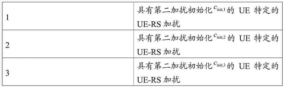
这里,cinit,0至少部分在用于UE-RS加扰初始化的第一新的RRC配置的参数,例如RRC_SCID0上确定。cinit,1至少部分在用于UE-RS加扰初始化的第一新的RRC配置的参数,例如RRC_SCID1上确定。cinit,2至少部分在用于UE-RS加扰初始化的第一新的RRC配置的参数,例如RRC_SCID2上确定。cinit,3至少部分用于UE-RS加扰初始化的第一新的RRC配置的参数,例如RRC_SCID3上确定。Here, c init,0 is at least partly determined on the parameters of the first new RRC configuration for UE-RS scrambling initialization, eg RRC_SCID0. c init,1 is determined at least in part on the parameters of the first new RRC configuration for UE-RS scrambling initialization, eg RRC_SCID1. c init,2 is at least partly determined on the parameters of the first new RRC configuration for UE-RS scrambling initialization, eg RRC_SCID2. c init,3 is at least partly used for UE-RS scrambling initialization of the first new RRC configured parameters, for example determined on RRC_SCID3.
根据如在表21中定义的两比特UE-RS加扰方法IE,网络可以通过如在下面的场景中设置新的两比特IE并配置新的RRC参数来执行图10中所示的下行链路传输。According to the two-bit UE-RS scrambling method IE as defined in Table 21, the network can perform the downlink shown in Figure 10 by setting a new two-bit IE and configuring new RRC parameters as in the following scenario transmission.
在一个场景中,UE4和UE5两者都被配置有子帧n中的两比特IE=2,即,第一UE特定的UE-RS加扰。网络分配不同的RRC_SCID2用于UE4和UE5,使得用于UE4和UE5的两个UE-RS在接收器处不相干合并,或者两个加扰初始化参数不相同。UE4与RRH1关联,并且UE5与RRH2关联。因为UE4的位置接近RRH1而UE5的位置接近RRH2(其位置远离RRH1),所以网络可以在子帧中调度相同的PRB用于UE4和UE5而不着重考虑干扰功率。UE特定的UE-RS加扰确保在接收器处来自RRH1和RRH2的两个UE-RS不会相干合并。In one scenario, both UE4 and UE5 are configured with two-bit IE=2 in subframe n, ie first UE-specific UE-RS scrambling. The network allocates different RRC_SCID2 for UE4 and UE5, so that the two UE-RSs for UE4 and UE5 are combined non-coherently at the receiver, or the two scrambling initialization parameters are not the same. UE4 is associated with RRH1 and UE5 is associated with RRH2. Since UE4 is located close to RRH1 and UE5 is located close to RRH2 (its location is far away from RRH1), the network can schedule the same PRB in a subframe for UE4 and UE5 without focusing on the interference power. UE-specific UE-RS scrambling ensures that the two UE-RSs from RRH1 and RRH2 are not coherently combined at the receiver.
在另一场景中,UE1被配置有子帧n中的两比特IE=1,即,第二UE特定的UE-RS加扰。这里,如此配置RRC_SCID1使得它生成与Rel-10UE-RS的一样的UE1的cinit,1。Rel-11UE1和Rel-10UE0可以在相同的PRB中MU-MIMO复用并且它们的UE-RS可以正交复用,而不影响Rel-10UE0的解调性能。In another scenario, UE1 is configured with two bits of IE=1 in subframe n, ie, the second UE-specific UE-RS scrambling. Here, RRC_SCID1 is configured such that it generates c init,1 of UE1 the same as that of Rel-10 UE-RS. Rel-11UE1 and Rel-10UE0 can be MU-MIMO multiplexed in the same PRB and their UE-RSs can be orthogonally multiplexed without affecting the demodulation performance of Rel-10UE0.
在又另一场景中,UE2和UE3两者都被配置有子帧n中的两比特IE=0,即,第一UE特定的UE-RS加扰。网络分配相同的RRC_SCID0用于UE2和UE3,使得用于UE2和UE3的两个UE-RS可以被使得正交。两个Rel-11UE的UE-RS可以正交复用用于MU-MIMO操作。In yet another scenario, both UE2 and UE3 are configured with two bits of IE=0 in subframe n, ie first UE specific UE-RS scrambling. The network allocates the same RRC_SCID0 for UE2 and UE3 so that the two UE-RSs for UE2 and UE3 can be made orthogonal. UE-RSs of two Rel-11 UEs can be multiplexed orthogonally for MU-MIMO operation.
在又一场景中,UE3被配置有子帧n+1中的两比特IE=3,即,第二UE特定的UE-RS加扰。这里,如此配置RRC_SCID3使得它生成与Rel-10UE-RS的一样的UE3的cinit,1。Rel-11UE3和Rel-10UE0可以在相同的PRB中MU-MIMO复用并且它们的UE-RS可以正交复用,而不影响Rel-10UE0的解调性能。In yet another scenario, UE3 is configured with two-bit IE=3 in subframe n+1, ie, second UE-specific UE-RS scrambling. Here, RRC_SCID3 is configured such that it generates c init,1 of UE3 the same as that of Rel-10 UE-RS. Rel-11UE3 and Rel-10UE0 can be MU-MIMO multiplexed in the same PRB and their UE-RSs can be orthogonally multiplexed without affecting the demodulation performance of Rel-10UE0.
在另一实施例中,在表22中定义的新的两比特信息单元(IE),UE-RS加扰方法IE,被嵌入在DL授权DCI格式(例如,DCI格式2B/2C)中,用于指示四种候选UE-RS加扰方法:Rel-10兼容的(小区特定的)UE-RS加扰;TP特定的UE-RS加扰;根据第一加扰初始化,例如cinit,0的UE特定的UE-RS加扰;以及根据第二加扰初始化cinit,1的UE特定的UE-RS加扰中的UE-RS加扰方法。在一个示例中,nSCID被固定为0。在另一示例中,nSCID被固定为1。将nSCID设置为常数,可以节省两比特开销。因此,如在图11中的DCI格式2B-2和图12中的DCI格式2B-4中,通过从DCI格式2B中移除SC-ID比特并用UE-RS加扰方法IE代替它,可以布置新的DL授权DCI格式。In another embodiment, a new two-bit information element (IE), UE-RS Scrambling Method IE, defined in Table 22, is embedded in a DL grant DCI format (e.g., DCI format 2B/2C) with Indicates four candidate UE-RS scrambling methods: Rel-10 compatible ( cell-specific) UE-RS scrambling; TP-specific UE-RS scrambling; UE-specific UE-RS scrambling; and a UE-RS scrambling method in UE-specific UE-RS scrambling according to the second scrambling initialization c init,1 . In one example, n SCID is fixed at zero. In another example, n SCID is fixed at 1. Setting n SCID to a constant saves two bits of overhead. Therefore, as in DCI format 2B-2 in FIG. 11 and DCI format 2B-4 in FIG. 12 , by removing the SC-ID bit from DCI format 2B and replacing it with UE-RS scrambling method IE, it is possible to arrange New DL authorized DCI format.
表22UE-RS加扰方法的动态指示(示例11)Table 22 Dynamic indication of UE-RS scrambling method (Example 11)
这里,cinit,0至少部分在用于UE-RS加扰初始化的第一新的RRC配置的参数,例如RRC_SCID0上确定。cinit,1至少部分在用于UE-RS加扰初始化的第一新的RRC配置的参数,例如RRC_SCID1上确定。Here, c init,0 is at least partly determined on the parameters of the first new RRC configuration for UE-RS scrambling initialization, eg RRC_SCID0. c init,1 is determined at least in part on the parameters of the first new RRC configuration for UE-RS scrambling initialization, eg RRC_SCID1.
存在很多方法用于实施TP特定的UE-RS加扰。例如,加扰初始化cinit至少部分通过RRC配置的TP-ID来确定。在另一示例中,加扰初始化cinit至少部分通过CSI-RS配置中的resourceConfig、subframeConfig和antennaPortCount中的至少一个来确定。There are many methods for implementing TP specific UE-RS scrambling. For example, the scrambling initialization c init is determined at least in part by the RRC configured TP-ID. In another example, the scrambling initialization c init is at least partially determined by at least one of resourceConfig, subframeConfig and antennaPortCount in the CSI-RS configuration.
根据如在表22中定义的两比特UE-RS加扰方法IE,网络可以通过如在下面的场景中设置新的两比特IE并配置新的RRC参数来执行图10中所示的下行链路传输。According to the two-bit UE-RS scrambling method IE as defined in Table 22, the network can perform the downlink shown in Figure 10 by setting a new two-bit IE and configuring new RRC parameters as in the following scenario transmission.
在一个场景中,UE4和UE5两者都被配置有子帧n中的两比特IE=2,即,TP特定的UE-RS加扰。UE4与RRH1关联,并且UE5与RRH2关联。因为UE4的位置接近RRH1而UE5的位置接近RRH2(其位置远离RRH1),所以网络可以在子帧中调度相同的PRB用于UE4和UE5而不着重考虑干扰功率。TP特定的UE-RS加扰确保在接收器处来自RRH1和RRH2的两个UE-RS不会相干合并。In one scenario, both UE4 and UE5 are configured with two-bit IE=2 in subframe n, ie, TP-specific UE-RS scrambling. UE4 is associated with RRH1 and UE5 is associated with RRH2. Since UE4 is located close to RRH1 and UE5 is located close to RRH2 (its location is far away from RRH1), the network can schedule the same PRB in a subframe for UE4 and UE5 without focusing on the interference power. TP-specific UE-RS scrambling ensures that the two UE-RSs from RRH1 and RRH2 are not coherently combined at the receiver.
在另一场景中,UE1被配置有子帧n中的两比特IE=0,即,Rel-10兼容的UE-RS加扰。Rel-11UE1和Rel-10UE0可以在相同的PRB中MU-MIMO复用并且它们的UE-RS可以正交复用,而不影响Rel-10UE0的解调性能。In another scenario, UE1 is configured with two bits of IE=0 in subframe n, ie Rel-10 compatible UE-RS scrambling. Rel-11UE1 and Rel-10UE0 can be MU-MIMO multiplexed in the same PRB and their UE-RSs can be orthogonally multiplexed without affecting the demodulation performance of Rel-10UE0.
在又另一场景中,UE2和UE3两者都被配置有子帧n中的两比特IE=1,即,UE特定的UE-RS加扰。网络分配相同的RRC UE-RS加扰初始化参数用于UE2和UE3,使得用于UE2和UE3的两个UE-RS可以正交复用,或者两个加扰初始化参数相同。两个Rel-11UE的UE-RS可以正交复用用于MU-MIMO操作。In yet another scenario, both UE2 and UE3 are configured with two bits of IE=1 in subframe n, ie UE-specific UE-RS scrambling. The network allocates the same RRC UE-RS scrambling initialization parameters for UE2 and UE3, so that the two UE-RSs for UE2 and UE3 can be orthogonally multiplexed, or the two scrambling initialization parameters are the same. UE-RSs of two Rel-11 UEs can be multiplexed orthogonally for MU-MIMO operation.
在又另一场景中,UE3被配置有子帧n+1中的两比特IE=0,即,Rel-10兼容的UE-RS加扰。Rel-11UE3和Rel-10UE0可以在相同的PRB中MU-MIMO复用并且它们的UE-RS可以正交复用,而不影响Rel-10UE0的解调性能。In yet another scenario, UE3 is configured with two-bit IE=0 in subframe n+1, ie Rel-10 compatible UE-RS scrambling. Rel-11UE3 and Rel-10UE0 can be MU-MIMO multiplexed in the same PRB and their UE-RSs can be orthogonally multiplexed without affecting the demodulation performance of Rel-10UE0.
在另一个实施例中,在表23中定义的新的两比特信息单元(IE),UE-RS加扰方法IE,被嵌入在DL授权DCI格式(例如,DCI格式2B/2C)中,用于指示四个候选UE-RS加扰方法中的UE-RS加扰方法。In another embodiment, a new two-bit information element (IE) defined in Table 23, UE-RS Scrambling Method IE, is embedded in a DL grant DCI format (e.g., DCI format 2B/2C) with to indicate the UE-RS scrambling method among the four candidate UE-RS scrambling methods.
表23UE-RS加扰方法的动态指示(示例12)TABLE 23 Dynamic indication of UE-RS scrambling method (Example 12)
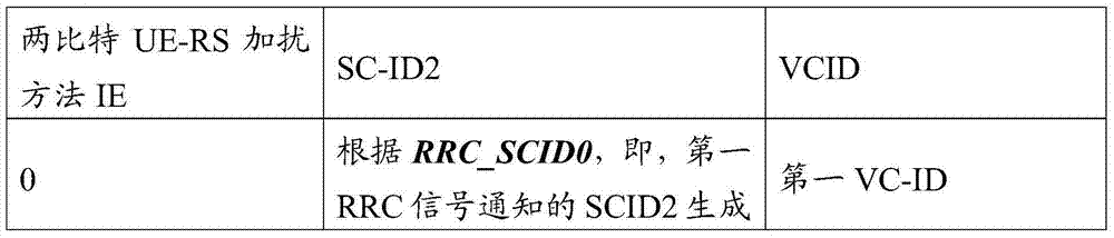

对于候选VC-ID的信号通知,候选VC-ID可以通过RRC信令明确地配置。可选择地,候选VC-ID可以在CSI-RS配置中配置的VC-ID。例如,第一VC-ID是第一CSI-RS配置中的VC-ID,并且第二VC-ID是第二CSI-RS配置中的VC-ID。For signaling of candidate VC-IDs, candidate VC-IDs may be explicitly configured through RRC signaling. Optionally, the candidate VC-ID may be the VC-ID configured in the CSI-RS configuration. For example, the first VC-ID is the VC-ID in the first CSI-RS configuration, and the second VC-ID is the VC-ID in the second CSI-RS configuration.
在一个示例中,使用所指示的VC-ID和SCIID2根据下面的等式来执行UE-RS加扰初始化:In one example, UE-RS scrambling initialization is performed according to the following equation using the indicated VC-ID and SCIID2:

在动态信令的一个示例中,用与用DCI格式2B和2C指示加扰标识的相同方法来指示SCID2。通过新添加的比特来指示VC-ID,如表24中所示。In one example of dynamic signaling, SCID2 is indicated in the same way as the scrambling identification is indicated with DCI formats 2B and 2C. VC-ID is indicated by a newly added bit as shown in Table 24.
表24用于UE-RS加扰方法的动态指示的码点Table 24 Codepoints for dynamic indication of UE-RS scrambling method


上行链路PUCCH资源分配Uplink PUCCH resource allocation
在一些传统系统(3GPP LTE Rel8、9、10)中,当通过PDCCH动态地调度用于PDSCH的UE的HARQ-ACK反馈时,将携载HARQ-ACK的PUCCH资源(PUCCH格式1a/1b)动态地配置到UE。在此情形中,用于HARQ-ACK的PUCCH资源数目


要用于在时隙ns中的PUCCH的传输的物理资源块由如下提供:The physical resource blocks to be used for the transmission of the PUCCH in the slot n s are provided by:

其中变量m取决于PUCCH格式。对于格式1、1a和1b,m通过以下确定:The variable m depends on the PUCCH format. For

一些Rel-11UE可以被配置为生成UE特定的或TP特定的UL RS基本序列(类型1基本序列),而其他Rel-11UE和传统UE根据3GPP Rel-8/9/10规范(例如,根据3GPP TS36.211/36.212/36.213v8.x.x、v9.x.x、v10.x.x)可以被配置为生成传统的(小区特定的)UL RS基本序列(类型0基本序列)。为了减少在两种类型的UE之间的干扰和它对系统性能的不利影响,在每个PRB中仅复用使用一种类型的基本序列生成的PUCCH是有益的。图9示出该构思。Some Rel-11 UEs can be configured to generate UE-specific or TP-specific UL RS basic sequences (
如图9中所示,PRB#0仅由根据传统的(Rel-8)机制发送PUCCH的类型0UE的PUCCH来使用。然而,PRB#1和PRB#2仅由发送使用UE特定的或TP特定的基本序列生成的PUCCH的类型1的UE的PUCCH来使用。在此,用于映射使用传统的UL RS基本序列生成的PUCCH的PRB被表示为PUCCH PRB,而用于映射使用UE特定的或TP特定的基本序列生成的PUCCH的PRB被表示为E-PUCCH PRB。As shown in FIG. 9 ,
在图9中,PUCCH PRB被划分成两个地带,其中第一地带(地带1)包括PRB#0,而第二地带(地带2)包括PRB#1和PRB#2。PUCCH地带由以下至少之一来定义:In FIG. 9, the PUCCH PRB is divided into two zones, where the first zone (zone 1) includes
一组PRB;A set of PRBs;
UL RS基本序列;UL RS basic sequence;
在一个示例中,地带1和地带2根据下面的表25定义。In one example,
表25PUCCH地带划分示例1Table 25 PUCCH zone division example 1
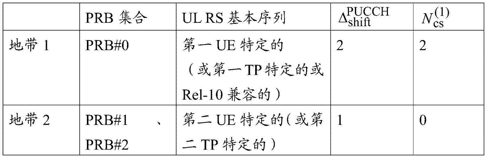
在另一示例中,地带1和地带2根据下面的表26定义,其中共同的值集合被分配用于两个地带的

表26PUCCH地带划分示例2Table 26 PUCCH zone division example 2

eNodeB可以配置地带特定的UL功率控制(PC)用于补偿在每个RP处的接收功率,并且抵抗(combat)远近效应。对于地带特定的UL PC,eNodeB地带特定地配置用于PUCCH UL PC的至少一个参数,其中LTE-A PUCCHUL PC等式如下:The eNodeB can configure zone-specific UL power control (PC) for compensating the received power at each RP and combating the near-far effect. For a zone-specific UL PC, the eNodeB zone-specifically configures at least one parameter for the PUCCH UL PC, where the LTE-A PUCCH UL PC equation is as follows:
在一个示例中,值P0_PUCCH,PLc,ΔF_PUCCH(F),ΔTxD(F'),g(i)中的至少一个是地带特定地配置的/更新的/测量的。例如,P0_PUCCH,ΔF_PUCCH(F),ΔTxD(F')可以被地带特定地RRC配置。依靠小区特定的CRS或RP特定的CSI-RS,PLc可以地带特定地测量。g(i)可以被地带特定地更新,例如,一种类型的TPC命令通过更新用于地带1的g(i)来更新地带1的PPUCCH(i);而另一种类型的TPC命令通过更新用于地带2的g(i)来更新地带2的PPUCCH(i)。In one example, at least one of the values P 0_PUCCH , PL c , ΔF_PUCCH (F), ΔTxD (F′), g(i) is zone-specifically configured/updated/measured. For example, P 0_PUCCH , Δ F_PUCCH (F), Δ TxD (F') may be zone-specifically RRC configured. PL c can be zone-specifically measured by means of cell-specific CRS or RP-specific CSI-RS. g(i) can be zone-specifically updated, for example, one type of TPC command updates P PUCCH (i) for
当用于N个地带的地带特定的PC被配置用于UE时,UE记录(keep trackof)N个PUCCH功率控制等式和相关的参数。例如,当UE被配置有两个PUCCH地带和用于两个地带的地带特定的PC时,取决于eNodeB指令,UE使用第一(地带特定的)PC或第二(地带特定的)PC方法来发送PUCCH。When a zone-specific PC for N zones is configured for the UE, the UE keeps track of the N PUCCH power control equations and related parameters. For example, when a UE is configured with two PUCCH zones and zone-specific PCs for both zones, depending on eNodeB instructions, the UE uses either the first (zone-specific) PC or the second (zone-specific) PC method to Send PUCCH.
另外,例如通过指示虚拟小区ID的候选集合的RRC信令,一些Rel-11UE可以被配置有很多虚拟小区ID来生成UL RS序列。当这样的Rel-11 UE被指示为使用虚拟小区ID
序列组数目:u=(fgh(ns)+fss)mod30。Number of sequence groups: u=(f gh (n s )+f ss ) mod30.
序列组跳频:组跳频图案fgh(ns)对于PUSCH和PUCCH相同,并且通过以下提供Sequence group hopping: The group hopping pattern f gh (n s ) is the same for PUSCH and PUCCH and is provided by
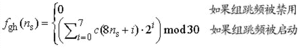
其中伪随机序列c(i)通过3GPP TS 36.211的7.2节来定义。在每个无线帧的开始处使用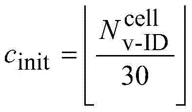
序列移位图案:序列移位图案fss定义在PUCCH和PUSCH之间不同。对于PUCCH,序列移位图案由
对于PUSCH,序列移位图案由
在另一示例中,对于PUCCH,序列移位图案

在另一示例中,对于PUSCH,序列移位图案

对于PUCCH,序列移位图案由
对于SRS,在第一示例的情况中,根据3GPP LTE Rel-8/9/10过程用

序列跳频:对于长度

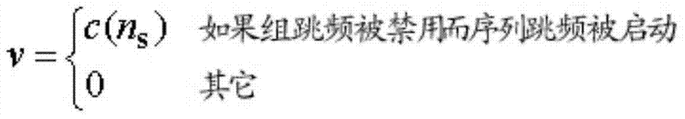
其中伪随机序列c(i)由3GPP TS36.211的7.2节提供。在每个无线帧的开始处使用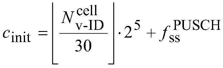
用于DM-RS的RS基本序列生成:根据Rel-8方法,使用根据以上计算的u和v的值。RS base sequence for DM-RS Generation: According to the Rel-8 method, using the values of u and v calculated according to the above.
在另一实施例中,图8或图10中的UE1被配置有CSI-RS配置1并被配置为接收UE特定地或TP特定地加扰的DL UE-RS。然后,UE1确定PUCCH格式1a/1b资源,并且取决于DL UE-RS加扰方法,即,Rel-10兼容的或UE特定的/TP特定的UE-RS加扰是否用于与HARQ-ACK反馈关联的PDSCH,UE1不同地生成它的基本序列。In another embodiment, UE1 in FIG. 8 or FIG. 10 is configured with CSI-
在一个示例中,UE1生成用于PUCCH格式1a/1b的UL RS基本序列,并且在时间-频率资源中映射PUCCH格式1a/1b,如表27中所示。In one example, UE1 generates UL RS basic sequence for PUCCH format 1a/1b and maps PUCCH format 1a/1b in time-frequency resources as shown in Table 27.
表27取决于DL RS加扰方法的基本RS序列生成TABLE 27 Basic RS sequence generation depending on DL RS scrambling method


概括表27中的示例,UE1生成用于PUCCH格式1a/1b的UL RS基本序列,并且取决于DL RS加扰方法在时间-频率资源中映射PUCCH格式1a/1b,如表28和表29中所示。To summarize the example in Table 27, UE1 generates UL RS basic sequences for PUCCH format 1a/1b and maps PUCCH format 1a/1b in time-frequency resources depending on the DL RS scrambling method as in Table 28 and Table 29 shown.
表28取决于DL RS加扰方法的基本RS序列生成TABLE 28 Basic RS sequence generation depending on DL RS scrambling method

在表29中,UE1取决于DL RS加扰方法,确定PUCCH地带,如表28中所示。用于PUCCH地带划分的一些示例可以在表25和表26中找到。In Table 29, UE1 determines the PUCCH zone as shown in Table 28 depending on the DL RS scrambling method. Some examples for PUCCH zone division can be found in Table 25 and Table 26.
表29取决于DL RS加扰方法的PUCCH地带分配Table 29 PUCCH zone allocation depending on DL RS scrambling method

在一个实施例中,用于PUCCH传输的PUCCH地带通过相应的DL授权DCI格式来指示。现在描述指示PUCCH地带的一些示例码点。In one embodiment, the PUCCH zone used for PUCCH transmission is indicated by a corresponding DL grant DCI format. Some example codepoints indicating PUCCH zones are now described.
在第一示例中,新的字段被附加到DL授权DCI格式来明确地指示用于ACK/NACK传输的PUCCH地带。例如,要指示两个候选地带中的一个地带,新的一比特字段被附加到DL授权DCI格式。在下面的表30中示出一个示例。In a first example, a new field is appended to the DL grant DCI format to explicitly indicate the PUCCH zone for ACK/NACK transmission. For example, to indicate one of two candidate zones, a new one-bit field is appended to the DL grant DCI format. An example is shown in Table 30 below.
表30取决于SCID的PUCCH地带分配Table 30 PUCCH zone allocation depending on SCID
在另一示例中,通过加扰ID值(例如,Rel-10中DCI格式2B和2C中的SCID)来隐含地指示PUCCH地带)。当存在用于SCID的两个候选值时,在表31中示出一个示例指示方法。当存在四个候选值时可以使用类似于表31的表。In another example, the PUCCH zone is implicitly indicated by a scrambling ID value (eg, SCID in DCI formats 2B and 2C in Rel-10). An example indication method is shown in Table 31 when there are two candidate values for SCID. A table similar to Table 31 may be used when there are four candidate values.
表31取决于SCID的PUCCH地带分配Table 31 PUCCH zone allocation depending on SCID
在第三示例中,通过VC-ID值,或TP-ID来隐含地指示PUCCH地带。当存在用于VC-ID或者TP-ID的两个候选值时,在表32中示出一个示例指示方法。当存在四个候选值时可以使用类似于表32的表。In a third example, the PUCCH zone is implicitly indicated by a VC-ID value, or TP-ID. An example indication method is shown in Table 32 when there are two candidate values for VC-ID or TP-ID. A table similar to Table 32 may be used when there are four candidate values.
表32取决于VC-ID和TP-ID的PUCCH地带分配Table 32 PUCCH zone allocation depending on VC-ID and TP-ID
在第四示例中,通过DL授权的位置,即,取决于在PDCCH还是ePDCCH上发送DL授权,来隐含地指示PUCCH地带。在下面的表33中示出一个示例。In a fourth example, the PUCCH zone is implicitly indicated by the location of the DL grant, ie depending on whether the DL grant is sent on PDCCH or ePDCCH. An example is shown in Table 33 below.
表33取决于DL授权位置的PUCCH PC方法Table 33 PUCCH PC method depending on DL grant position
在另一实施例中,通过相应的DL授权DCI格式来指示用于PUCCH传输的PUCCH功率控制方法。现在描述指示PUCCH功率控制方法的一些示例码点。In another embodiment, the PUCCH power control method for PUCCH transmission is indicated by the corresponding DL grant DCI format. Some example code points indicating the PUCCH power control method are now described.
在第一示例中,新的字段被附加到DL授权DCI格式来明确地指示用于ACK/NACK传输的PUCCH功率控制方法。例如,要指示两个候选地带中的一个地带,新的一比特字段被附加到DL授权DCI格式。在下面的表34中示出一个示例。In a first example, a new field is appended to the DL grant DCI format to explicitly indicate the PUCCH power control method for ACK/NACK transmission. For example, to indicate one of two candidate zones, a new one-bit field is appended to the DL grant DCI format. An example is shown in Table 34 below.
表34取决于SCID的PUCCH PC方法Table 34 PUCCH PC method depending on SCID
在第二示例中,通过加扰ID值(例如,Rel-10中DCI格式2B和2C中的SCID)来隐含地指示PUCCH PC方法。当存在用于SCID的两个候选值时,在下面的表35中示出一个示例指示方法。当存在四个候选值时可以使用类似于表35的表。In a second example, the PUCCH PC method is implicitly indicated by a scrambling ID value (eg, SCID in DCI formats 2B and 2C in Rel-10). When there are two candidate values for SCID, an example indication method is shown in Table 35 below. A table similar to Table 35 can be used when there are four candidate values.
表35取决于SCID的PUCCH PC方法Table 35 PUCCH PC method depending on SCID
在第三示例中,通过VC-ID值、或TP-ID来隐含地指示PUCCH PC方法。当存在用于VC-ID或者TP-ID的两个候选值时,在表36中示出一个示例指示方法。当存在四个候选值时可以使用类似于表36的表。In a third example, the PUCCH PC method is implicitly indicated by a VC-ID value, or TP-ID. An example indication method is shown in Table 36 when there are two candidate values for VC-ID or TP-ID. A table similar to Table 36 may be used when there are four candidate values.
表36取决于VC-ID和TP-ID的PUCCH PC方法Table 36 PUCCH PC method depending on VC-ID and TP-ID
在第四示例中,通过DL授权的位置,即,取决于是在PDCCH还是ePDCCH上发送DL授权,来隐含地指示PUCCH PC方法。在下面的表37中示出一个示例方法。In a fourth example, the PUCCH PC method is implicitly indicated by the location of the DL grant, ie depending on whether the DL grant is sent on PDCCH or ePDCCH. An example method is shown in Table 37 below.
表37取决于DL授权位置的PUCCH PC方法Table 37 PUCCH PC method depending on DL grant position
在一些实施例中,通过DL授权DCI格式中的IE来联合指示用于A/NPUCCH的PUCCH PC方法和PUCCH地带。在下面的表38、表39、表40、In some embodiments, the PUCCH PC method and PUCCH zone for A/NPUCCH are jointly indicated by an IE in the DL grant DCI format. In the following Table 38, Table 39, Table 40,
和表41中示出联合指示的一些示例。Some examples of joint indications are shown in Table 41.
表38取决于SCID的PUCCH地带和PC方法分配Table 38 PUCCH zone and PC method allocation depending on SCID
表39取决于SCID的PUCCH地带和PC方法分配Table 39 PUCCH zone and PC method allocation depending on SCID
表40取决于VC-ID或TP-ID的PUCCH地带和PC方法分配Table 40 PUCCH zone and PC method allocation depending on VC-ID or TP-ID
表41取决于DL授权位置的PUCCH地带和PC方法分配Table 41 PUCCH zone and PC method allocation depending on DL grant position
在一个实施例中,在图8或图10中的UE1被配置为生成TP特定的或UE特定的UL RS序列,并被配置有CSI-RS配置1。然后,与通过PDCCH调度的与PDSCH对应的UE1的HARQ-ACK的
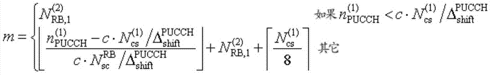
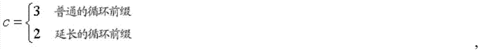
其中


在另一个实施例中,在图8或图10中的UE1被配置为生成TP特定的或UE特定的UL RS序列,并被配置有CSI-RS配置1。然后,与通过PDCCH调度的PDSCH对应的UE1的HARQ-ACK的
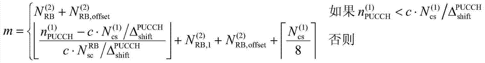

其中


在一些实施例中,在图8或图10中的UE1被配置为生成TP特定的或UE特定的UL RS序列,并且被配置有CSI-RS配置1。然后,与通过PDCCH调度的PDSCH对应的UE1的HARQ-ACK的

在一个示例中,候选的数目N=4,因此两比特信息单元(IE)被包括在例如与DL授权对应的PDCCH中。在此情况中,4个候选

表42

在另一示例中,候选的数目N=2,因此一比特信息单元(IE)被包括在例如与DL授权对应的PDCCH中。在此示例中,2个候选
表43

用于PUCCH ACK/NACK的基本序列生成方法可以取决于所指示的


表44取决于

在一些实施例中,通过
表45取决于

在另一实施例中,在图8或图10中的UE2被配置有CSI-RS配置1和2。然后,UE2确定PUCCH格式1a/1b,并且取决于在调度与HARQ-ACK反馈关联的PDSCH的DL授权DCI格式中指示的一比特VCID字段和SC-ID值中的至少一个来不同地生成它的基本序列。In another embodiment, UE2 in FIG. 8 or FIG. 10 is configured with CSI-
为了确定与通过PDCCH或ePDCCH调度的PDSCH对应的UE2的HARQ-ACK的

取决于UE2被配置有小区特定的R10兼容的基本序列生成还是UE特定的(或TP特定的)基本序列生成(其中配置可以通过RRC信令来执行),UE被指示为使用不同的

在一个示例中,UE2根据表46中所示的SC-ID在时间-频率资源中映射PUCCH格式1a/1b。在表46中,SC-ID的值确定noffset。In one example, UE2 maps PUCCH format 1a/1b in time-frequency resources according to the SC-ID shown in Table 46. In Table 46, the value of SC-ID determines n offset .
表46基本RS序列生成示例Table 46 Basic RS sequence generation example
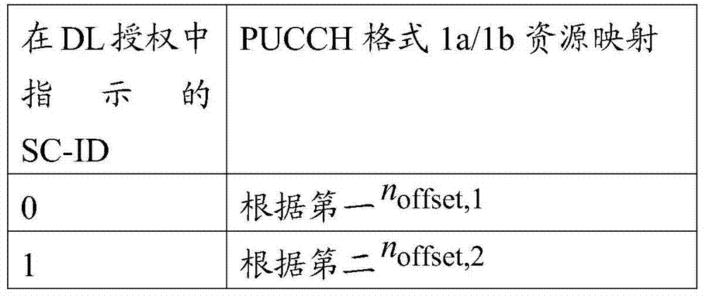
在另一示例中,UE2根据包括在DL DCI格式,例如DCI格式1A、2、2A、2B、2C等中的明确的比特来在时间-频率资源中映射PUCCH格式1a/1b,其中明确的比特确定noffset。In another example, UE2 maps PUCCH format 1a/1b in time-frequency resources according to explicit bits included in DL DCI formats, such as DCI formats 1A, 2, 2A, 2B, 2C, etc., where explicit bits Determine noffset .
对于确定发送HARQ-ACK所在的PRB的变量m,现在描述两个选择。For the variable m that determines the PRB at which the HARQ-ACK is transmitted, two options are now described.
在第一选择中,通过如下向


其中在很多候选值当中动态地指示
在一个示例中,UE2生成用于PUCCH格式1a/1b的UL RS基本序列,并且根据下行链路DCI格式(DL授权)中的一比特VCID字段在时间-频率资源中映射PUCCH格式1a/1b,如表47中所示。In one example, UE2 generates UL RS basic sequence for PUCCH format 1a/1b, and maps PUCCH format 1a/1b in time-frequency resource according to one-bit VCID field in downlink DCI format (DL grant), As shown in Table 47.
表47基本RS序列生成示例Table 47 Basic RS sequence generation example

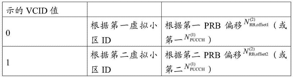
在另一示例中,UE2生成用于PUCCH格式1a/1b的UL RS基本序列,并且根据DL授权中的SC-ID和一比特VCID字段两者在时间-频率资源中映射PUCCH格式1a/1b,如表48中所示。在表中,VCID字段的值确定
表48基本RS序列生成示例Table 48 Basic RS sequence generation example

在第二选择中,如下通过在很多的

在一个示例中,UE2生成用于PUCCH格式1a/1b的UL RS基本序列,并且根据下行链路DCI格式(DL授权)中的一比特VCID字段在时间-频率资源中映射PUCCH格式1a/1b,如表49中所示。In one example, UE2 generates UL RS basic sequence for PUCCH format 1a/1b, and maps PUCCH format 1a/1b in time-frequency resource according to one-bit VCID field in downlink DCI format (DL grant), As shown in Table 49.
表49基本RS序列生成示例Table 49 Basic RS sequence generation example

在另一示例中,UE2生成用于PUCCH格式1a/1b的UL RS基本序列,并且根据DL授权中的SC-ID和一比特VCID字段两者在时间-频率资源中映射PUCCH格式1a/1b,如表50中所示。在表50中,VCID字段的值确定而SC-ID的值确定noffset。In another example, UE2 generates UL RS basic sequence for PUCCH format 1a/1b, and maps PUCCH format 1a/1b in time-frequency resource according to both SC-ID and one-bit VCID field in DL grant, As shown in Table 50. In Table 50, the value of the VCID field determines And the value of SC-ID determines n offset .
表50基本RS序列生成示例Table 50 Basic RS sequence generation example
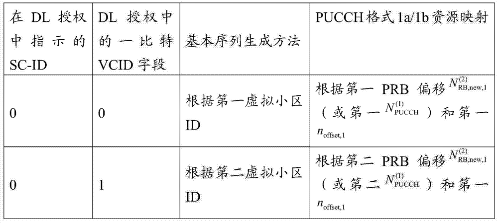
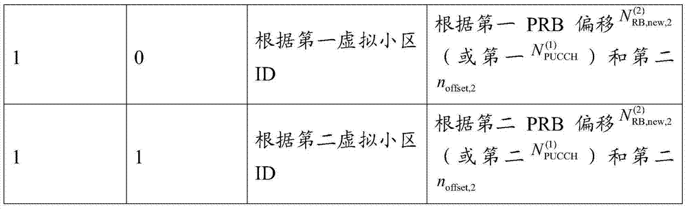
在另一实施例中,在图8或图10中的UE2被配置有CSI-RS配置1和2。然后,UE2确定PUCCH格式2/2a/2b资源,并取决于RRC配置的虚拟小区ID、或VCID不同地生成它的基本序列。PUCCH格式2/2a/2b被配置用于周期性的CQI/PMI/RI报告。例如,用于周期性的CQI/PMI/RI的Rel-11配置包括VCID。更具体地,用于周期性的报告的RRC消息可以通过添加新的字段VCID来构建。作为另一示例,CSI-RS配置包括VCID和周期性的CQI/PMI//RI配置。In another embodiment, UE2 in FIG. 8 or FIG. 10 is configured with CSI-
虽然已经使用示范性实施例描述了本公开,但是对于本领域的技术人员可以想到各种改变和修改。本公开意图涵盖落在所附权利要求的范围之内的这些改变和修改。Although the present disclosure has been described using an exemplary embodiment, various changes and modifications may occur to those skilled in the art. The present disclosure is intended to cover such changes and modifications as fall within the scope of the appended claims.
Claims (27)


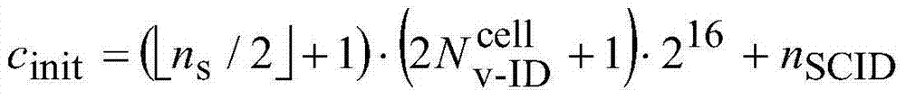


Applications Claiming Priority (13)
| Application Number | Priority Date | Filing Date | Title |
|---|---|---|---|
| US201161515730P | 2011-08-05 | 2011-08-05 | |
| US61/515,730 | 2011-08-05 | ||
| US201161525605P | 2011-08-19 | 2011-08-19 | |
| US61/525,605 | 2011-08-19 | ||
| US201161554891P | 2011-11-02 | 2011-11-02 | |
| US61/554,891 | 2011-11-02 | ||
| US201161565885P | 2011-12-01 | 2011-12-01 | |
| US61/565,885 | 2011-12-01 | ||
| US201261651885P | 2012-05-25 | 2012-05-25 | |
| US61/651,885 | 2012-05-25 | ||
| US13/564,469 | 2012-08-01 | ||
| US13/564,469 US8995385B2 (en) | 2011-08-05 | 2012-08-01 | Apparatus and method for UE-specific demodulation reference signal scrambling |
| PCT/KR2012/006235 WO2013022244A2 (en) | 2011-08-05 | 2012-08-06 | Apparatus and method for ue-specific demodulation reference signal scrambling |
Publications (2)
| Publication Number | Publication Date |
|---|---|
| CN103891232A true CN103891232A (en) | 2014-06-25 |
| CN103891232B CN103891232B (en) | 2017-05-10 |
Family
ID=47626908
Family Applications (1)
| Application Number | Title | Priority Date | Filing Date |
|---|---|---|---|
| CN201280049078.1A Active CN103891232B (en) | 2011-08-05 | 2012-08-06 | Apparatus and method for UE-specific demodulation reference signal scrambling |
Country Status (6)
| Country | Link |
|---|---|
| US (1) | US8995385B2 (en) |
| EP (1) | EP2740248B1 (en) |
| JP (1) | JP6105582B2 (en) |
| KR (1) | KR101979810B1 (en) |
| CN (1) | CN103891232B (en) |
| WO (1) | WO2013022244A2 (en) |
Cited By (7)
| Publication number | Priority date | Publication date | Assignee | Title |
|---|---|---|---|---|
| CN105634707A (en) * | 2015-12-31 | 2016-06-01 | 深圳市金立通信设备有限公司 | Information transmission method, base station and terminal |
| CN110603735A (en) * | 2017-03-10 | 2019-12-20 | 株式会社Ntt都科摩 | User terminal and wireless communication method |
| CN112119595A (en) * | 2019-04-19 | 2020-12-22 | Oppo广东移动通信有限公司 | Signal scrambling method and device, and communication equipment |
| CN112655180A (en) * | 2018-09-05 | 2021-04-13 | 三星电子株式会社 | Method and apparatus for generating reference signal sequence for PAPR reduction in mobile communication system |
| CN113273127A (en) * | 2019-01-11 | 2021-08-17 | 苹果公司 | System and method for physical downlink control channel candidate selection |
| CN113329367A (en) * | 2015-09-25 | 2021-08-31 | 创新技术实验室株式会社 | Method and device for configuring DM-RS for V2X |
| CN114450981A (en) * | 2019-10-01 | 2022-05-06 | 联想(新加坡)私人有限公司 | Determining a time to perform an update |
Families Citing this family (87)
| Publication number | Priority date | Publication date | Assignee | Title |
|---|---|---|---|---|
| CN103563270A (en) | 2011-02-11 | 2014-02-05 | 韩国电子通信研究院 | Wireless communication system using multiple transmission and reception points |
| US20120269140A1 (en) * | 2011-04-25 | 2012-10-25 | Samsung Electronics Co., Ltd. | Downlink control signaling for coordinated multipoint transmission |
| WO2013010305A1 (en) | 2011-07-15 | 2013-01-24 | Panasonic Corporation | Method of scrambling signals, transmission point device and user equipment using the method |
| US11671947B2 (en) | 2011-07-15 | 2023-06-06 | Sun Patent Trust | Reception apparatus and reception method |
| US9130723B2 (en) * | 2011-08-12 | 2015-09-08 | Lg Electronics Inc. | Method and device for acquiring resource for uplink control channel in wireless communication system |
| US9794955B2 (en) * | 2011-08-15 | 2017-10-17 | Texas Instruments Incorporated | Configuration of CSI-RS for CoMP feedback |
| JP5781694B2 (en) * | 2011-08-16 | 2015-09-24 | エルジー エレクトロニクス インコーポレイティド | Method and apparatus for transmitting uplink reference signal in wireless communication system |
| EP2761771A4 (en) * | 2011-09-29 | 2015-06-24 | Intel Corp | Higher order mu-mimo for lte-a |
| US20140233525A1 (en) * | 2011-10-13 | 2014-08-21 | Lg Electronics Inc. | Method and apparatus for allocating resources in wireless communication system |
| KR101902578B1 (en) * | 2011-10-14 | 2018-10-01 | 애플 인크. | Method and apparatus for transmitting reference signal in wireless communication system |
| CN103095395B (en) * | 2011-11-02 | 2017-09-22 | 中兴通讯股份有限公司 | PUCCH resource allocation method, transmission method, device and system |
| KR102066278B1 (en) | 2011-11-07 | 2020-01-15 | 애플 인크. | Apparatus and Method for Transmitting Reference Signal, Channel Estimation Apparatus and Method using the same |
| JP5959830B2 (en) * | 2011-11-10 | 2016-08-02 | 株式会社Nttドコモ | Radio communication system, radio base station apparatus, user terminal, and radio communication method |
| JP5905972B2 (en) * | 2011-11-13 | 2016-04-20 | エルジー エレクトロニクス インコーポレイティド | Method and apparatus for transmitting control information in a wireless communication system |
| US9716576B2 (en) * | 2011-12-06 | 2017-07-25 | Lg Electronics Inc. | Method and device for transmitting reference signal in wireless communication system |
| US9166729B2 (en) * | 2011-12-14 | 2015-10-20 | Marvell World Trade Ltd. | Enhanced demodulation reference signal (DM-RS) design |
| EP2795827B1 (en) | 2011-12-20 | 2019-09-04 | Marvell World Trade Ltd. | Reference signal design for coordinated multipoint transmission |
| US9769806B2 (en) * | 2012-01-17 | 2017-09-19 | Texas Instruments Incorporated | Resource configuration for EPDCCH |
| US9345013B2 (en) | 2012-01-18 | 2016-05-17 | Lg Electronics Inc. | Method and apparatus for enhanced control channel-based operation in wireless communication system |
| US9241327B2 (en) * | 2012-01-23 | 2016-01-19 | Intel Corporation | LTE enhancements for small packet transmissions |
| WO2013112189A1 (en) * | 2012-01-23 | 2013-08-01 | Intel Corporation | Network assisted user association and offloading techniques for integrated multi-rat heterogeneous networks |
| KR102070780B1 (en) | 2012-02-20 | 2020-01-29 | 엘지전자 주식회사 | Method and apparatus for transmitting uplink signal in wireless communication system |
| US9474050B2 (en) | 2012-02-20 | 2016-10-18 | Lg Electronics Inc. | Method and apparatus for transmitting uplink signal in wireless communication system |
| US9686110B2 (en) | 2012-02-20 | 2017-06-20 | Lg Electronics Inc. | Method and apparatus for transmitting uplink signal in wireless communication system |
| JP5379254B2 (en) | 2012-03-14 | 2013-12-25 | シャープ株式会社 | Mobile station apparatus, base station apparatus, communication method, integrated circuit, and radio communication system |
| JP5314779B2 (en) * | 2012-03-14 | 2013-10-16 | シャープ株式会社 | Mobile station apparatus, base station apparatus, communication method, integrated circuit, and radio communication system |
| JP5379256B2 (en) * | 2012-03-14 | 2013-12-25 | シャープ株式会社 | Mobile station apparatus, base station apparatus, communication method, integrated circuit, and radio communication system |
| JP5379255B2 (en) * | 2012-03-14 | 2013-12-25 | シャープ株式会社 | Mobile station apparatus, base station apparatus, communication method, integrated circuit, and radio communication system |
| US8731124B2 (en) | 2012-03-28 | 2014-05-20 | Telefonaktiebolaget Lm Ericsson (Publ) | Signaling of sequence generator initialization parameters for uplink reference signal generation |
| KR102210081B1 (en) * | 2012-05-11 | 2021-02-01 | 팬텍 주식회사 | Method and Apparatus for Transmitting and Receiving Reference Signal in Wireless Communication System |
| US9854570B2 (en) | 2012-06-07 | 2017-12-26 | Qualcomm Incorporated | Signaling of virtual cell ID |
| CN103959886B (en) | 2012-08-02 | 2018-04-17 | 太阳专利信托公司 | Wireless communication terminal, base station device, and resource allocation method |
| US9155089B2 (en) * | 2012-08-10 | 2015-10-06 | Qualcomm Incorporated | Cell ID and antenna port configurations for EPDCCH |
| CN103687042B (en) * | 2012-09-03 | 2018-05-15 | 中兴通讯股份有限公司 | The transmission method and system of a kind of Physical Downlink Shared Channel |
| GB2506153A (en) * | 2012-09-21 | 2014-03-26 | Sony Corp | A base station punctures OFDM reference symbols to provide fast physical-layer signaling of periods during which a terminal may enter a low power mode. |
| US9295048B2 (en) | 2012-09-24 | 2016-03-22 | Qualcomm Incorporated | Method and apparatus for supporting hybrid carrier aggregation |
| US9814030B2 (en) * | 2012-09-27 | 2017-11-07 | Lg Electronics Inc. | Method and apparatus for transmitting or receiving reference signal in wireless communication system |
| US9497755B2 (en) * | 2012-10-08 | 2016-11-15 | Lg Electronics Inc. | Method for transceiving control information, and apparatus for same |
| EP2906005B1 (en) * | 2012-11-01 | 2020-03-11 | Huawei Technologies Co., Ltd. | Control channel detection method, user equipment and base station |
| US9288698B2 (en) * | 2012-11-02 | 2016-03-15 | Intel Corporation | Handling signal quality measurements in a wireless communication network |
| US9407302B2 (en) * | 2012-12-03 | 2016-08-02 | Intel Corporation | Communication device, mobile terminal, method for requesting information and method for providing information |
| GB2508871A (en) * | 2012-12-13 | 2014-06-18 | Broadcom Corp | Providing a UE with scrambling code initialization parameters associated with an interfering signal |
| CN103973391A (en) * | 2013-01-24 | 2014-08-06 | 北京三星通信技术研究有限公司 | Method and equipment for reporting channel state information (CSI) |
| KR20150104155A (en) * | 2013-01-25 | 2015-09-14 | 후지쯔 가부시끼가이샤 | Signaling indication method, user equipment and base station for demodulating reference signal |
| EP2768273B1 (en) * | 2013-02-15 | 2020-04-01 | Samsung Electronics Co., Ltd. | Scrambling sequence generation method for use in device-to-device communication |
| KR20140103018A (en) * | 2013-02-15 | 2014-08-25 | 삼성전자주식회사 | Method and apparatus for scrambling sequence generation in device-to-device communication |
| US9706522B2 (en) * | 2013-03-01 | 2017-07-11 | Intel IP Corporation | Wireless local area network (WLAN) traffic offloading |
| WO2014137105A1 (en) * | 2013-03-03 | 2014-09-12 | 엘지전자 주식회사 | Method for receiving control information on epdcch |
| JP6155075B2 (en) * | 2013-04-05 | 2017-06-28 | 株式会社Nttドコモ | User terminal, small base station, and communication method |
| US9680522B2 (en) | 2013-05-09 | 2017-06-13 | Texas Instruments Incorporated | Dynamic reconfiguration of uplink transmission in a TDD wireless communication system |
| WO2014185748A1 (en) | 2013-05-16 | 2014-11-20 | 엘지전자 주식회사 | Signal transmission method for coverage improvement and apparatus for same |
| JP6250799B2 (en) | 2013-06-12 | 2017-12-20 | コンヴィーダ ワイヤレス, エルエルシー | Context and power control information management for proximity services |
| KR20160021869A (en) | 2013-06-21 | 2016-02-26 | 콘비다 와이어리스, 엘엘씨 | Context management |
| EP3020182B1 (en) | 2013-07-10 | 2020-09-09 | Convida Wireless, LLC | Context-aware proximity services |
| US9844039B2 (en) * | 2013-09-26 | 2017-12-12 | Sharp Kabushiki Kaisha | Terminal, base station, and communication method |
| JP6376757B2 (en) * | 2014-01-14 | 2018-08-22 | 株式会社Nttドコモ | User terminal, radio base station, and radio communication method |
| WO2015109585A1 (en) * | 2014-01-26 | 2015-07-30 | 华为技术有限公司 | User equipment, base station and cell discovery method |
| WO2016010123A1 (en) * | 2014-07-18 | 2016-01-21 | シャープ株式会社 | Terminal device, base station device, and communication method |
| CN105376188B (en) * | 2014-08-26 | 2019-08-09 | 上海朗帛通信技术有限公司 | Scrambling method and device in LAA communication |
| US9955462B2 (en) | 2014-09-26 | 2018-04-24 | Qualcomm Incorporated | Ultra-low latency LTE control data communication |
| US9980257B2 (en) | 2014-09-26 | 2018-05-22 | Qualcomm Incorporated | Ultra-low latency LTE reference signal transmission |
| CN107251503B (en) * | 2015-03-13 | 2020-08-14 | 诺基亚技术有限公司 | Non-orthogonal cover codes for co-channel network isolation |
| KR102320997B1 (en) * | 2015-03-31 | 2021-11-03 | 삼성전자 주식회사 | Method and Device for transmitting and receiving a data between a user equipment and a base station |
| US20170048014A1 (en) * | 2015-08-13 | 2017-02-16 | Spreadtrum Hong Kong Limited | Apparatus and method for generating scrambling codes for repetition transmissions |
| WO2017075746A1 (en) * | 2015-11-02 | 2017-05-11 | Qualcomm Incorporated | Techniques for managing cell identifiers and other parameters for flexible duplex operations |
| US20180323931A1 (en) * | 2015-11-10 | 2018-11-08 | Ntt Docomo, Inc. | Base station, user apparatus, reference signal transmission method and signal reception method |
| US20170245263A1 (en) * | 2016-02-05 | 2017-08-24 | Mediatek Inc. | PUCCH Resource Allocation and Peak to Average Power Ratio Reduction in eLAA |
| US10716020B2 (en) * | 2016-02-23 | 2020-07-14 | Samsung Electronics Co., Ltd. | Method and apparatus for measurement reference signal |
| US10547426B2 (en) | 2016-03-14 | 2020-01-28 | Samsung Electronics Co., Ltd. | Transmission of sounding reference signals in communication systems with carrier aggregation |
| TWI642313B (en) * | 2016-04-01 | 2018-11-21 | 聯發科技股份有限公司 | Method of pucch resource allocation and user equipment |
| JP2019169751A (en) * | 2016-08-10 | 2019-10-03 | 株式会社Nttドコモ | User device and communication method |
| US10530622B2 (en) * | 2016-11-03 | 2020-01-07 | Huawei Technologies Co., Ltd. | Methods and apparatuses for transmitting and receiving uplink reference signals using non-orthogonal sequences |
| CN109257147B (en) | 2017-01-24 | 2020-01-17 | 华为技术有限公司 | Transmission method and device |
| SG11201906996TA (en) * | 2017-02-03 | 2019-08-27 | Sharp Kk | Base station apparatus, terminal apparatus, and communication method for base station apparatus and terminal apparatus |
| US10608770B2 (en) * | 2017-03-23 | 2020-03-31 | Qualcomm Incorporated | Techniques and apparatuses for channel processing backwards compatibility |
| US10798704B2 (en) * | 2017-04-28 | 2020-10-06 | Qualcomm Incorporated | Reference signal design for slot aggregation |
| US10841062B2 (en) | 2017-05-04 | 2020-11-17 | Qualcomm Incorporated | Sequence for reference signals during beam refinement |
| CN109547174B (en) * | 2017-08-10 | 2022-05-24 | 华为技术有限公司 | Time configuration method, network equipment and UE |
| PE20201377A1 (en) * | 2017-11-16 | 2020-11-30 | Ntt Docomo Inc | USER TERMINAL AND RADIO COMMUNICATION METHOD |
| CN118413426A (en) * | 2018-11-13 | 2024-07-30 | 华为技术有限公司 | A method and device for generating and processing a sequence |
| US20190149294A1 (en) * | 2019-01-14 | 2019-05-16 | Intel IP Corporation | Csi-rs sequence generation and mapping and dmrs scrambling id configuration |
| CN113141238B (en) * | 2020-01-20 | 2023-11-24 | 维沃移动通信有限公司 | Data transmission methods and equipment |
| EP4101231A1 (en) | 2020-03-05 | 2022-12-14 | Google LLC | User equipment identity management for coordinating base stations |
| WO2021208109A1 (en) * | 2020-04-18 | 2021-10-21 | 华为技术有限公司 | Communication method and apparatus |
| WO2022016342A1 (en) * | 2020-07-20 | 2022-01-27 | Oppo广东移动通信有限公司 | Channel scrambling method and terminal device |
| CN114449655B (en) * | 2020-11-02 | 2025-05-27 | 大唐移动通信设备有限公司 | Channel transmission method, device, terminal equipment, network equipment and storage medium |
| US11876656B2 (en) * | 2021-04-27 | 2024-01-16 | Qualcomm Incorporated | Scalable TD RS pattern and dynamic indication |
Citations (5)
| Publication number | Priority date | Publication date | Assignee | Title |
|---|---|---|---|---|
| CN101682419A (en) * | 2008-03-17 | 2010-03-24 | Lg电子株式会社 | Method of transmitting reference signal and transmitter using the same |
| US20100323709A1 (en) * | 2009-06-18 | 2010-12-23 | Samsung Electronics Co., Ltd. | Method and system for indicating method used to scramble dedicated reference signals |
| US20110077038A1 (en) * | 2009-09-30 | 2011-03-31 | Qualcomm Incorporated | Scrambling sequence initialization for coordinated multi-point transmissions |
| US20110085503A1 (en) * | 2009-10-12 | 2011-04-14 | Samsung Electronics Co., Ltd. | Method and system of multi-layer beamforming |
| CN102067645A (en) * | 2008-06-25 | 2011-05-18 | 高通股份有限公司 | Improving scrambling under an extended physical-layer cell identity space |
Family Cites Families (6)
| Publication number | Priority date | Publication date | Assignee | Title |
|---|---|---|---|---|
| US7729237B2 (en) | 2008-03-17 | 2010-06-01 | Lg Electronics Inc. | Method of transmitting reference signal and transmitter using the same |
| KR101715397B1 (en) * | 2009-04-22 | 2017-03-13 | 엘지전자 주식회사 | Apparatus and method for transmitting reference signal in wireless communication system |
| CN102056309A (en) | 2009-11-02 | 2011-05-11 | 北京三星通信技术研究有限公司 | Method and device for transmitting dedicated reference signals |
| US9118470B2 (en) * | 2010-04-01 | 2015-08-25 | Lg Electronics Inc. | Control information transmission method and a device therefor |
| KR101868622B1 (en) * | 2010-06-17 | 2018-06-18 | 엘지전자 주식회사 | Method and apparatus for transmitting and receiving r-pdcch |
| EP2398180A1 (en) * | 2010-06-21 | 2011-12-21 | Panasonic Corporation | Configuration of uplink and downlink grant search spaces in a OFDM-based mobile communication system |
-
2012
- 2012-08-01 US US13/564,469 patent/US8995385B2/en active Active
- 2012-08-06 WO PCT/KR2012/006235 patent/WO2013022244A2/en not_active Ceased
- 2012-08-06 KR KR1020147005943A patent/KR101979810B1/en active Active
- 2012-08-06 CN CN201280049078.1A patent/CN103891232B/en active Active
- 2012-08-06 JP JP2014524921A patent/JP6105582B2/en active Active
- 2012-08-06 EP EP12821601.7A patent/EP2740248B1/en active Active
Patent Citations (5)
| Publication number | Priority date | Publication date | Assignee | Title |
|---|---|---|---|---|
| CN101682419A (en) * | 2008-03-17 | 2010-03-24 | Lg电子株式会社 | Method of transmitting reference signal and transmitter using the same |
| CN102067645A (en) * | 2008-06-25 | 2011-05-18 | 高通股份有限公司 | Improving scrambling under an extended physical-layer cell identity space |
| US20100323709A1 (en) * | 2009-06-18 | 2010-12-23 | Samsung Electronics Co., Ltd. | Method and system for indicating method used to scramble dedicated reference signals |
| US20110077038A1 (en) * | 2009-09-30 | 2011-03-31 | Qualcomm Incorporated | Scrambling sequence initialization for coordinated multi-point transmissions |
| US20110085503A1 (en) * | 2009-10-12 | 2011-04-14 | Samsung Electronics Co., Ltd. | Method and system of multi-layer beamforming |
Non-Patent Citations (2)
| Title |
|---|
| SAMSUNG: "Scrambling for DM-RS", 《3GPP TSG RAN WG1 MEETING #62 R1-104973》 * |
| SAMSUNG: "Scrambling sequence for CoMP", 《3GPP TSG RAN WG1 MEETING #60 R1-101178》 * |
Cited By (13)
| Publication number | Priority date | Publication date | Assignee | Title |
|---|---|---|---|---|
| US11997659B2 (en) | 2015-09-25 | 2024-05-28 | Innovative Technology Lab Co., Ltd. | Method and apparatus for configuring DM-RS for V2X |
| CN113329367A (en) * | 2015-09-25 | 2021-08-31 | 创新技术实验室株式会社 | Method and device for configuring DM-RS for V2X |
| CN113329367B (en) * | 2015-09-25 | 2024-06-14 | 创新技术实验室株式会社 | Method and apparatus for configuring DM-RS for V2X |
| US12309752B2 (en) | 2015-09-25 | 2025-05-20 | Innovative Technology Lab Co., Ltd. | Method and apparatus for configuring DM-RS for V2X |
| CN105634707B (en) * | 2015-12-31 | 2019-04-23 | 深圳市金立通信设备有限公司 | A kind of method, base station and the terminal of information transmission |
| CN105634707A (en) * | 2015-12-31 | 2016-06-01 | 深圳市金立通信设备有限公司 | Information transmission method, base station and terminal |
| CN110603735A (en) * | 2017-03-10 | 2019-12-20 | 株式会社Ntt都科摩 | User terminal and wireless communication method |
| CN112655180A (en) * | 2018-09-05 | 2021-04-13 | 三星电子株式会社 | Method and apparatus for generating reference signal sequence for PAPR reduction in mobile communication system |
| CN113273127A (en) * | 2019-01-11 | 2021-08-17 | 苹果公司 | System and method for physical downlink control channel candidate selection |
| CN113273127B (en) * | 2019-01-11 | 2024-04-05 | 苹果公司 | System and method for physical downlink control channel candidate selection |
| US12003435B2 (en) | 2019-01-11 | 2024-06-04 | Apple Inc. | Systems and methods for physical downlink control channel candidate selection |
| CN112119595A (en) * | 2019-04-19 | 2020-12-22 | Oppo广东移动通信有限公司 | Signal scrambling method and device, and communication equipment |
| CN114450981A (en) * | 2019-10-01 | 2022-05-06 | 联想(新加坡)私人有限公司 | Determining a time to perform an update |
Also Published As
| Publication number | Publication date |
|---|---|
| KR101979810B1 (en) | 2019-08-28 |
| US20130034064A1 (en) | 2013-02-07 |
| JP2014527750A (en) | 2014-10-16 |
| CN103891232B (en) | 2017-05-10 |
| WO2013022244A2 (en) | 2013-02-14 |
| US8995385B2 (en) | 2015-03-31 |
| EP2740248A4 (en) | 2015-04-22 |
| KR20140071355A (en) | 2014-06-11 |
| EP2740248B1 (en) | 2019-02-27 |
| EP2740248A2 (en) | 2014-06-11 |
| JP6105582B2 (en) | 2017-03-29 |
| WO2013022244A3 (en) | 2013-04-25 |
Similar Documents
| Publication | Publication Date | Title |
|---|---|---|
| CN103891232B (en) | Apparatus and method for UE-specific demodulation reference signal scrambling | |
| US10932290B2 (en) | Uplink reference signal transmitting or receiving method in wireless communication system, and apparatus therefor | |
| EP3522471B1 (en) | Method for transmitting or receiving signal in wireless communication system and device therefor | |
| CN104272820B (en) | Terminal installation, communication means and base station apparatus | |
| CN103765966B (en) | Control the terminal device and its method of uplink signal transmission power | |
| RU2563249C2 (en) | Radio base station, user terminal and radio communication method | |
| JP5610861B2 (en) | Mobile station apparatus, base station apparatus, radio communication system, radio communication method, and integrated circuit | |
| CN103947246B (en) | Mobile station device, base station device, wireless communication system, wireless communication method, and integrated circuit | |
| JP6671173B2 (en) | Terminal device, base station device, communication method, and integrated circuit | |
| JP6439192B2 (en) | Terminal device, base station device, integrated circuit, and wireless communication method | |
| CN104322124A (en) | Terminal, base station, communication method, and integrated circuit | |
| US10855500B2 (en) | Terminal apparatus, base station apparatus, communication method, and integrated circuit | |
| EP3142266A1 (en) | Method and apparatus for transmitting data in d2d communication | |
| JP6260031B2 (en) | User apparatus, base station apparatus, integrated circuit, and communication method | |
| CN102598810A (en) | Method and device for controlling transmission power in wireless communication system | |
| CN102413572A (en) | DMRS (demodulation reference signal) as well as sending method and device thereof | |
| CN105191448A (en) | Power control method and apparatus in wireless access system | |
| WO2015002237A1 (en) | Terminal device, base station device, integrated circuit, and communication method | |
| WO2017002794A1 (en) | Terminal device, base station, communication method, and integrated circuit | |
| JPWO2015159877A1 (en) | Terminal apparatus, base station apparatus, integrated circuit, and communication method | |
| WO2017022617A1 (en) | Terminal device, base station device, communication method, and integrated circuit | |
| WO2017195655A1 (en) | Terminal device, base station device, and communication method | |
| JP6128692B2 (en) | Mobile station apparatus, base station apparatus and communication method | |
| JP5530254B2 (en) | Mobile station apparatus, base station apparatus, radio communication system, radio communication method, and integrated circuit | |
| WO2015005428A1 (en) | Terminal apparatus, base station apparatus, integrated circuit, and communication method |
Legal Events
| Date | Code | Title | Description |
|---|---|---|---|
| C06 | Publication | ||
| PB01 | Publication | ||
| C10 | Entry into substantive examination | ||
| SE01 | Entry into force of request for substantive examination | ||
| GR01 | Patent grant | ||
| GR01 | Patent grant |