CN103718414A - Photovoltaic voltage regulation - Google Patents
Photovoltaic voltage regulation Download PDFInfo
- Publication number
- CN103718414A CN103718414A CN201280038486.7A CN201280038486A CN103718414A CN 103718414 A CN103718414 A CN 103718414A CN 201280038486 A CN201280038486 A CN 201280038486A CN 103718414 A CN103718414 A CN 103718414A
- Authority
- CN
- China
- Prior art keywords
- power
- photovoltaic
- voltage
- strings
- string
- Prior art date
- Legal status (The legal status is an assumption and is not a legal conclusion. Google has not performed a legal analysis and makes no representation as to the accuracy of the status listed.)
- Granted
Links
Images


Classifications
-
- H—ELECTRICITY
- H02—GENERATION; CONVERSION OR DISTRIBUTION OF ELECTRIC POWER
- H02J—CIRCUIT ARRANGEMENTS OR SYSTEMS FOR SUPPLYING OR DISTRIBUTING ELECTRIC POWER; SYSTEMS FOR STORING ELECTRIC ENERGY
- H02J3/00—Circuit arrangements for AC mains or AC distribution networks
- H02J3/38—Arrangements for parallely feeding a single network by two or more generators, converters or transformers
- H02J3/381—Dispersed generators
-
- H—ELECTRICITY
- H02—GENERATION; CONVERSION OR DISTRIBUTION OF ELECTRIC POWER
- H02S—GENERATION OF ELECTRIC POWER BY CONVERSION OF INFRARED RADIATION, VISIBLE LIGHT OR ULTRAVIOLET LIGHT, e.g. USING PHOTOVOLTAIC [PV] MODULES
- H02S40/00—Components or accessories in combination with PV modules, not provided for in groups H02S10/00 - H02S30/00
- H02S40/30—Electrical components
- H02S40/32—Electrical components comprising DC/AC inverter means associated with the PV module itself, e.g. AC modules
-
- H—ELECTRICITY
- H02—GENERATION; CONVERSION OR DISTRIBUTION OF ELECTRIC POWER
- H02S—GENERATION OF ELECTRIC POWER BY CONVERSION OF INFRARED RADIATION, VISIBLE LIGHT OR ULTRAVIOLET LIGHT, e.g. USING PHOTOVOLTAIC [PV] MODULES
- H02S40/00—Components or accessories in combination with PV modules, not provided for in groups H02S10/00 - H02S30/00
- H02S40/30—Electrical components
- H02S40/34—Electrical components comprising specially adapted electrical connection means to be structurally associated with the PV module, e.g. junction boxes
-
- H—ELECTRICITY
- H02—GENERATION; CONVERSION OR DISTRIBUTION OF ELECTRIC POWER
- H02S—GENERATION OF ELECTRIC POWER BY CONVERSION OF INFRARED RADIATION, VISIBLE LIGHT OR ULTRAVIOLET LIGHT, e.g. USING PHOTOVOLTAIC [PV] MODULES
- H02S50/00—Monitoring or testing of PV systems, e.g. load balancing or fault identification
-
- H02J2101/24—
-
- Y—GENERAL TAGGING OF NEW TECHNOLOGICAL DEVELOPMENTS; GENERAL TAGGING OF CROSS-SECTIONAL TECHNOLOGIES SPANNING OVER SEVERAL SECTIONS OF THE IPC; TECHNICAL SUBJECTS COVERED BY FORMER USPC CROSS-REFERENCE ART COLLECTIONS [XRACs] AND DIGESTS
- Y02—TECHNOLOGIES OR APPLICATIONS FOR MITIGATION OR ADAPTATION AGAINST CLIMATE CHANGE
- Y02E—REDUCTION OF GREENHOUSE GAS [GHG] EMISSIONS, RELATED TO ENERGY GENERATION, TRANSMISSION OR DISTRIBUTION
- Y02E10/00—Energy generation through renewable energy sources
- Y02E10/50—Photovoltaic [PV] energy
- Y02E10/56—Power conversion systems, e.g. maximum power point trackers
Landscapes
- Engineering & Computer Science (AREA)
- Power Engineering (AREA)
- Supply And Distribution Of Alternating Current (AREA)
- Control Of Electrical Variables (AREA)
Abstract
一种光伏系统包括:光伏发电机,其包括串列,其中每个串列包括一个或多个光伏电池;功率转换器;开关;和控制器。功率转换器被配置为将由光伏发电机提供的直流(DC)功率转换为交流(AC)功率,并且输出AC功率。每个开关关联于串列中的一个,并且被配置为当设置为第一设置时,将关联的串列连接到功率转换器,使得被第一串列产生的功率可流到功率转换器。每个开关也被配置为当设置为第二设置时,从功率转换器断开串列。控制器被配置为通过用控制开关的设置选择性地将光伏发电机的串列连接到功率转换器以控制光伏发电机提供的功率。
A photovoltaic system includes: a photovoltaic generator comprising strings, each string including one or more photovoltaic cells; a power converter; switches; and a controller. The power converter is configured to convert direct current (DC) power supplied by the photovoltaic generator into alternating current (AC) power and output AC power. Each switch is associated with one of the strings and is configured to connect the associated string to the power converter when set to a first setting, such that power generated by the first string can flow to the power converter. Each switch is also configured to disconnect the string from the power converter when set to a second setting. The controller is configured to selectively connect the strings of the photovoltaic generator to the power converter by controlling the settings of the control switches to control the power supplied by the photovoltaic generator.
Description
背景background
光伏系统使用太阳能电池将光能到电能。典型的光伏系统包括几个部件,包括光伏电池、机械连接和电连接、配件、以及用于调节和/或修改光伏系统产生的电流的控制器。Photovoltaic systems use solar cells to convert light energy into electricity. A typical photovoltaic system includes several components, including photovoltaic cells, mechanical and electrical connections, accessories, and controllers for regulating and/or modifying the electrical current produced by the photovoltaic system.
本文使用的以下术语描述光伏系统的各种部件和/或操作方面:The following terms are used herein to describe various components and/or operational aspects of photovoltaic systems:
PV 光伏PV Photovoltaic
DC 直流电DC direct current
AC 交流电AC alternating current
Voc 开路电压Voc open circuit voltage
VGRID 电网电压V GRID grid voltage
VNOM 标称电网电压V NOM Nominal grid voltage
IGRID 电网电流I GRID grid current
图1是典型的PV系统100的功能框图。光伏系统100包括将太阳光转换成电的光伏发电机101。在传统的PV系统中,诸如光伏系统100,系统产生的电压可以通过从PV发电机101提取适量的功率,将功率从PV发电机101传到转换器102以穿过到达功率吸收器103。根据一个实施方式,功率转换器102可包括电功率转换器。在典型的实施中,功率吸收器103是电力网(有时也被称为功率“电源”)。电网包括一个电力网络,该电力网络用于将产生、传输、控制和分配来自电力发电机的电力给网络上处于各个服务领域的电力消费者。功率转换器102将由PV发电机101提供的DC功率转换成可被分配到电网上的AC功率。FIG. 1 is a functional block diagram of a
图2是可被用于实施图1所示的系统的传统的PV电力系统200的更详细的框图。PV电力系统200包括太阳能电池阵列201,其包括太阳能电池(也被称为光伏电池)。太阳能电池是通过光电效应将太阳光能直接转换成电能的固态设备。太阳能电池产生DC电压。FIG. 2 is a more detailed block diagram of a conventional
太阳能电池阵列201被耦合到DC开关202。DC开关202可被关闭以将太阳能电池阵列201连接到DC电容器组204,或被打开以从DC电容器组204断开太阳能电池阵列201。当DC开关202被关闭并且太阳能电池阵列201正在产生电力,太阳能电池阵列201可提供DC电容器组204充电的电力。DC电容器组204也被连接到逆变器205。
逆变器205将来自电容器组204的DC电压输出转换成3-相(或在某些情况是2-相)脉冲AC电压。逆变器205输出脉冲AC电流到滤波器206。滤波器206将被逆变器205输出的脉冲AC电流转换成正弦AC电压。然后,正弦AC电压可被输出到电源电网209。如果AC电源开关207被关闭,那么被滤波器206输出的正弦AC电压则被功率变压器208接收。功率变压器208使得PV系统200输出的电压适应电网电压。这个配置允许PV系统200输出电到电源电网209。光伏系统200输出的电压不高于电网电压。
控制PV发电机(诸如太阳能电池阵列201)产生的电压是重要的,因为其有助于(a)增加太阳能面板产生的功率,和(b)减少功率转换器上的电压应力。如果功率吸收器103,诸如电网209,不能吸收PV发电机101产生的可用功率,PV电压将朝着开路电平(Voc)增加并且将最终产生功率转换器102上增加的电压应力。在传统的系统中,这是通过“过设计”功率转换器来解决的,使得功率转换器101可以可信赖地操作PV开路电压电平。过设计系统比没有过设计的系统具有更低的效率和更高的复杂性。Controlling the voltage produced by a PV generator such as
图3示出了传统系统用于解决这些问题的可选地方法。PV功率系统300包括以平行于PV发电机301的耗散电阻负载形式的预负载304。在功率吸收器303不能吸收PV发电机301产生的功率的情形中,预负载304可被激活以补充功率吸收器并且维持PV电压在对于功率转换器302来说是安全的电平。然而,预负载304的使用,可是非常的昂贵并且能够造成火灾。Figure 3 illustrates an alternative approach that conventional systems use to address these issues. The
概要summary
描述了用于调节光伏系统产生的电压的技术。例如,光伏系统包括包括布置成串列的光伏电池的光伏发电机。可配置的串列控制器可探测其中光伏发电机产生的电压应该被调节的事件并且选择性地连接或断开串列以调节光伏发电机提供的电压。Techniques for regulating voltage generated by photovoltaic systems are described. For example, photovoltaic systems include photovoltaic generators comprising photovoltaic cells arranged in series. A configurable string controller can detect events where the voltage produced by the photovoltaic generator should be regulated and selectively connect or disconnect the string to regulate the voltage provided by the photovoltaic generator.
光伏系统的实施例包括:包括串列的光伏发电机,其中每个串列包括一个或多个光伏电池;功率转换器;开关;以及控制器。功率转换器被配置为将光伏发电机提供的直流DC功率转换成交流AC功率,并且输出AC功率。每个开关关联于串列中的一个并且当设置为第一设置时被配置为将关联的串列连接到功率转换器,使得第一串列产生的功率可流进功率转换器。每个开关当设置为第二设置时也被配置为从功率转换器断开串列。控制器被配置为通过控制开关的设置有选择性地将光伏发电机的串列连接到功率转换器,来控制光伏发电机提供的功率。Embodiments of a photovoltaic system include: a photovoltaic generator comprising strings, where each string comprises one or more photovoltaic cells; a power converter; a switch; and a controller. The power converter is configured to convert direct current DC power provided by the photovoltaic generator into alternating current AC power and output the AC power. Each switch is associated with one of the strings and when set to the first setting is configured to connect the associated string to the power converter such that power generated by the first string can flow into the power converter. Each switch is also configured to disconnect the string from the power converter when set to the second setting. The controller is configured to control the power provided by the photovoltaic generators by controlling the setting of the switches to selectively connect the string of photovoltaic generators to the power converter.
光伏系统的实施可包括一个或多个以下特征。控制器被配置为监控功率吸收器的电压,并且控制器被配置为通过响应于功率吸收器的电压的降低有选择性地断开光伏发电机的串列,减少光伏发电机提供的到功率转换器的功率。控制器被配置为通过响应功率吸收器的增加电压有选择性地断开光伏发电机的串列,增加光伏发电机提供的到功率转换器的功率。控制器包括有形的、非暂时的计算机可读存储器、存储在存储器中包含处理器可执行的代码的模块、连接到存储器并且被配置为访问存储在存储器中的模块的处理器,和被配置为发送控制信号到开关的控制接口。模块包括电压控制模块、串列选择模块和控制信号模块。电压控制模块被配置为导致处理器:监控功率吸收器的电压以识别功率吸收器电压的改变,以确定是连接还是断开光伏发电机的一个或多个串列,从而响应于功率吸收器电压的改变,调节光伏发电机提供的功率。串列选择模块被配置为导致处理器:基于电压控制模块响应于功率吸收器的电压的改变而做出的关于光伏发电机的一个或多个串列应该被连接还是被断开的确定,选择光伏发电机中待被连接或被断开的一个或多个串列。控制信号模块被配置为导致处理器发送控制信号到开关以导致一个或多个串列被连接到功率转换器或从功率转换器断开。控制器还被配置为:接收指示功率转换器处于由光伏发电机提供的功率将逐渐斜坡上升的启动阶段的逆变器起动信号,断开超过用于提供起动电压的串列的任何串列,并且反复地连接串列以逐渐增加光伏发电机提供的功率。Implementations of photovoltaic systems can include one or more of the following features. The controller is configured to monitor the voltage of the power absorber, and the controller is configured to reduce the power transfer provided by the photovoltaic generator to power of the device. The controller is configured to increase the power provided by the photovoltaic generators to the power converter by selectively disconnecting the string of photovoltaic generators in response to the increased voltage of the power absorber. The controller includes a tangible, non-transitory computer readable memory, a module stored in the memory containing code executable by the processor, a processor connected to the memory and configured to access the module stored in the memory, and configured to Send the control signal to the control interface of the switch. The modules include a voltage control module, a string selection module and a control signal module. The voltage control module is configured to cause the processor to: monitor the voltage of the power absorber to identify a change in the power absorber voltage to determine whether to connect or disconnect the one or more strings of photovoltaic generators in response to the power absorber voltage Changes to adjust the power provided by the photovoltaic generator. The string selection module is configured to cause the processor to: select a One or more strings of photovoltaic generators to be connected or disconnected. The control signal module is configured to cause the processor to send control signals to the switches to cause one or more strings to be connected to or disconnected from the power converter. The controller is further configured to: receive an inverter start signal indicating that the power converter is in a start-up phase in which power supplied by the photovoltaic generator will gradually ramp up, disconnect any strings beyond those used to provide the start-up voltage, And connect the series repeatedly to gradually increase the power provided by the photovoltaic generator.
一种用于控制光伏系统功率输出的方法的实施例包括:接收指示功率转换器处于由光伏发电机提供的功率将逐渐斜坡上升的启动阶段的逆变器起动信号;断开超过用于提供起动电压的串列的任何串列;并且反复地连接串列以逐渐增加光伏发电机提供的功率。光伏系统包括光伏发电机,其包括串列,每个串列包括一个或多个光伏电池。An embodiment of a method for controlling power output of a photovoltaic system includes: receiving an inverter start signal indicating that the power converter is in a start-up phase in which power supplied by a photovoltaic generator will gradually ramp up; any series of series of voltages; and connecting the series repeatedly to gradually increase the power provided by the photovoltaic generator. A photovoltaic system includes a photovoltaic generator that includes strings, each string including one or more photovoltaic cells.
这样的方法的实施可包括一个或多个以下特征。每个串列关联于开关,并且断开超过用于提供起动电压的串列的任何串列包括发送控制信号到关联于将要被断开的串列中的每一个串列的每一个开关,以从功率转换器断开串列。连接串列以调节光伏发电机提供的光伏电压包括发送控制信号到关联于将要被连接的串列中的每一个串列的每个开关,以将串列连接到功率转换器。Implementations of such methods may include one or more of the following features. Each string is associated with a switch, and opening any string beyond the string used to provide the starting voltage includes sending a control signal to each switch associated with each of the strings to be opened, to Disconnect the string from the power converter. Connecting the strings to regulate the photovoltaic voltage provided by the photovoltaic generators includes sending a control signal to each switch associated with each of the strings to be connected to connect the strings to the power converter.
用于控制光伏系统功率输出的方法的实施例包括:监控与光伏系统关联的功率吸收器的电压,确定功率吸收器的电压是否已被降低,并且响应功率吸收器电压的降低:计算功率吸收器电压相对于关联于功率吸收器的标称电平的百分比,标称电平代表功率吸收器的期望电压电平;计算光伏发电机中将要被断开以减少光伏发电机提供的光伏电压的串列的数目,其中断开串列防止串列产生的功率到达将直流DC功率转换成功率吸收器的期望的交流AC功率的光伏系统的功率转换器;并且断开计算出的数目的串列以调节光伏发电机提供的光伏电压。光伏系统包括光伏发电机,其包括串列,每个串列包括一个或多个光伏电池。An embodiment of a method for controlling power output of a photovoltaic system includes: monitoring a voltage of a power absorber associated with a photovoltaic system, determining whether the voltage of the power absorber has been reduced, and responding to the decrease in the power absorber voltage: calculating the power absorber The percentage of voltage relative to the nominal level associated with the power absorber, which represents the desired voltage level of the power absorber; calculates the string of photovoltaic generators that will be disconnected to reduce the photovoltaic voltage supplied by the photovoltaic generator the number of strings where disconnecting the strings prevents the power generated by the strings from reaching the power converter of the photovoltaic system that converts the direct current DC power into the desired alternating current AC power of the power absorber; and disconnecting the calculated number of strings to Regulates the photovoltaic voltage provided by the photovoltaic generator. A photovoltaic system includes a photovoltaic generator that includes strings, each string including one or more photovoltaic cells.
这种方法的实施可包括一个或多个以下特征。确定功率吸收器的电压已增加,并且响应功率吸收器电压的增加:计算功率吸收器的电压相对于与功率吸收器关联的标称电平的百分比,标称电平代表功率吸收器的期望电压电平;计算光伏发电机中将要被连接以降低光伏发电机提供的光伏电压的串列的数目,其中连接串列允许串列产生的功率到达光伏系统的功率转换器;连接计算出数目的串列以增加光伏发电机提供的光伏电压。功率吸收器的电压因为低电压穿越(LVRT)事件而降低;并且将光伏发电机的电压减少与功率吸收器的电压的降低成比例的量。在LVRT事件之后,功率吸收器的电压增加,并且将光伏发电机提供的电压增加与功率吸收器的电压的增加成比例的量。每个串列关联于开关,并且其中断开计算出数目的串列以调节光伏发电机提供的光伏电压包括发送控制信号到关联于每个将要被断开的串列的开关以从功率转换器断开串列。连接计算出的数目的串列以调节光伏发电机提供的光伏电压包括发送控制信号到关联于将要被连接到的串列中的每一个的开关以连接串列到功率转换器。Implementations of such a method may include one or more of the following features. Determine that the voltage of the power sink has increased, and respond to the increase in the power sink voltage: Calculate the percentage of the voltage of the power sink relative to the nominal level associated with the power sink, which represents the expected voltage of the power sink level; calculate the number of strings in the photovoltaic generator that will be connected to reduce the photovoltaic voltage provided by the photovoltaic generator, wherein connecting the strings allows the power generated by the strings to reach the power converter of the photovoltaic system; connect the calculated number of strings column to increase the photovoltaic voltage provided by the photovoltaic generator. The voltage of the power absorber drops due to a low voltage ride through (LVRT) event; and the voltage of the photovoltaic generator is reduced by an amount proportional to the drop in voltage of the power absorber. After the LVRT event, the voltage of the power absorber increases, and the voltage provided by the photovoltaic generator is increased by an amount proportional to the increase in voltage of the power absorber. Each string is associated with a switch, and wherein disconnecting the calculated number of strings to regulate the photovoltaic voltage provided by the photovoltaic generator includes sending a control signal to a switch associated with each string to be disconnected to obtain the output from the power converter Disconnect the string. Connecting the calculated number of strings to regulate the photovoltaic voltage provided by the photovoltaic generator includes sending a control signal to a switch associated with each of the strings to be connected to connect the strings to the power converter.
控制光伏系统功率输出的方法的实施例包括:确定关联于光伏系统的功率吸收器的电压,确定光伏发电机的参考电压,参考电压表示光伏发电机的期望电压;确定光伏发电机的当前电压;确定参考电压和当前电压之间的差值;基于所述差值计算光伏发电机中要被连接或断开的串列的数目,其中断开串列防止串列产生的功率到达光伏系统的功率转换器,所述功率转换器将直流DC功率转换成功率吸收器期望的交流AC功率。连接串列允许串列产生的功率到达光伏系统的功率转换器。方法也包括连接或断开计算出数目的串列以调节光伏发电机提供的光伏电压。光伏系统包括光伏发电机,其包括串列,其中每个串列包括一个或多个光伏电池。An embodiment of a method of controlling power output of a photovoltaic system comprises: determining a voltage associated with a power absorber of the photovoltaic system, determining a reference voltage of a photovoltaic generator, the reference voltage representing a desired voltage of the photovoltaic generator; determining a current voltage of the photovoltaic generator; Determining the difference between the reference voltage and the current voltage; calculating based on said difference the number of strings in the photovoltaic generator to be connected or disconnected, wherein disconnecting the strings prevents the power generated by the strings from reaching the power of the photovoltaic system A converter that converts the direct current DC power to the alternating current AC power desired by the power absorber. Connecting the strings allows the power generated by the strings to reach the power converters of the photovoltaic system. The method also includes connecting or disconnecting the calculated number of strings to adjust the photovoltaic voltage provided by the photovoltaic generator. A photovoltaic system includes a photovoltaic generator that includes strings, where each string includes one or more photovoltaic cells.
这样方法的实施可包括一个或多个以下特征。每个串列关联于一个开关,并且这里断开串列以调节光伏发电机提供的光伏电压包括发送控制信号到关联于将要被断开的串列中的每一个的开关以从功率转换器断开串列。连接串列以调节光伏发电机提供的光伏电压包括发送控制信号到关联于将要被连接的串列中的每一个的开关以连接串列到功率转换器。Implementations of such methods may include one or more of the following features. Each string is associated with a switch, and here disconnecting the string to regulate the photovoltaic voltage provided by the photovoltaic generator includes sending a control signal to the switch associated with each of the strings to be disconnected to disconnect from the power converter. Open series. Connecting the strings to regulate the photovoltaic voltage provided by the photovoltaic generators includes sending control signals to switches associated with each of the strings to be connected to connect the strings to the power converters.
用于控制光伏系统功率输出的示例性系统包括光伏发电机,其包括串列,其中每个串列包括一个或多个光伏电池。系统包括用于接收逆变器起动信号的装置,该逆变器起动信号指示光伏系统的功率转换器处于光伏发电机提供的功率将逐渐斜坡上升的起动阶段;用于断开超过用于提供起动电压的串列的任何串列的装置;并且用于反复的连接串列以逐渐增加光伏发电机提供的功率的装置。An exemplary system for controlling power output of a photovoltaic system includes a photovoltaic generator comprising strings, wherein each string comprises one or more photovoltaic cells. The system includes means for receiving an inverter start signal indicating that the power converter of the photovoltaic system is in a start phase in which the power supplied by the photovoltaic generator will gradually ramp up; means for any series of series of voltages; and means for repeatedly connecting series to gradually increase the power supplied by the photovoltaic generator.
用于控制光伏系统功率输出的系统的实施可包括一个或多个以下特征。每个串列关联于一个开关,并且用于断开超过用于提供起动电压的串列的任何串列的装置还包括用于发送控制信号到关联于将要被断开的串列中的每一个的开关中的每一个以从功率转换器断开串列的装置。用于连接串列以调节光伏发电机提供的光伏电压的装置还包括用于发送控制信号到将要被连接的串列中的每一个相关联的开关中的每一个以将串列连接到功率转换器的装置。Implementations of a system for controlling power output of a photovoltaic system can include one or more of the following features. Each string is associated with a switch, and the means for disconnecting any string beyond the string used to provide the starting voltage further includes means for sending a control signal to each of the strings associated to be disconnected each of the switches to disconnect the device in series from the power converter. The means for connecting strings to regulate a photovoltaic voltage provided by a photovoltaic generator further includes each of the switches for sending control signals to each of the associated switches in the strings to be connected to connect the strings to power conversion device.
用于控制光伏系统功率输出的示例性系统包括光伏发电机,其包括串列,其中每个串列包括一个或多个光伏电池。系统包括用于监控与光伏系统关联的功率吸收器的电压的装置;用于确定功率吸收器的电压是否已降低的装置,并且响应功率吸收器电压的降低:用于计算功率吸收器电压相对于关联于功率吸收器的标称电平的百分比的装置,标称电平表示功率吸收器的期望的电压电平,计算光伏发电机中将要被断开以减少光伏发电机提供的光伏电压的串列的数目的装置,其中断开串列防止串列产生的功率到达光伏系统的功率转换器,所述光伏系统的功率转换器将直流DC功率转换成功率吸收器期望的交流AC功率,以及用于断开计算出的数目的串列以调节光伏发电机提供的光伏电压的装置。An exemplary system for controlling power output of a photovoltaic system includes a photovoltaic generator comprising strings, wherein each string comprises one or more photovoltaic cells. The system includes means for monitoring the voltage of a power absorber associated with the photovoltaic system; means for determining whether the voltage of the power absorber has decreased, and in response to the decrease in the power absorber voltage: for calculating the voltage of the power absorber relative to Means related to the percentage of the nominal level of the power absorber, the nominal level indicating the desired voltage level of the power absorber, calculating the string of photovoltaic generators that will be disconnected to reduce the photovoltaic voltage supplied by the photovoltaic generator means of the number of columns in which disconnecting the string prevents the power generated by the string from reaching the power converter of the photovoltaic system which converts the direct current DC power into the alternating current AC power desired by the power absorber, and with A device for disconnecting a calculated number of strings to regulate the photovoltaic voltage supplied by a photovoltaic generator.
用于控制光伏系统功率输出的系统的实施可包括一个或多个以下特征。系统包括用于确定功率吸收器的电压是否已增加的装置,并且响应于功率吸收器电压的增加,所述用于确定功率吸收器的电压是否已增加的装置包括:用于计算功率吸收器的电压相对于与功率吸收器关联的标称电压的百分比的装置,标称电压表示功率吸收器的期望电压电平;用于计算光伏发电机中将要被连接以降低光伏发电机提供的光伏电压的串列的数目的装置,其中连接串列允许串列产生的功率到达光伏系统的功率转换器;和用于连接计算出的数目的串列以增加光伏发电机提供的光伏电压的装置。功率吸收器的电压因为低电压穿越(LVRT)事件而降低,并且系统包括用于将光伏发电机的电压减少与功率吸收器电压的降低成比例的量的装置。在LVRT事件之后,功率吸收器的电压增加,并且系统包括用于将光伏发电机提供的电压增加与功率吸收器增加的电压成比例的量的装置。每个串列关联于一个开关,并且用于断开计算出数目的串列以调节光伏发电机提供的光伏电压的装置包括用于发送控制信号到关联于将要被断开的串列中的每一个的开关以从功率转换器断开串列的装置。用于连接计算出数目的串列以调节光伏发电机提供的光伏电压的装置还包括用于发送控制信号到关联于将被连接的串列中的每一个的开关以将串列连接到功率转换器的装置。Implementations of a system for controlling power output of a photovoltaic system can include one or more of the following features. The system includes means for determining whether the voltage of the power absorber has increased, and in response to the increase in the voltage of the power absorber, the means for determining whether the voltage of the power absorber has increased comprises: calculating a voltage of the power absorber Means of the voltage as a percentage of the nominal voltage associated with the power absorber, the nominal voltage indicating the desired voltage level of the power absorber; used in calculating the voltage in a photovoltaic generator to be connected to reduce the photovoltaic voltage provided by the photovoltaic generator means for the number of strings, wherein connecting the strings allows the power generated by the strings to reach the power converter of the photovoltaic system; and means for connecting the calculated number of strings to increase the photovoltaic voltage provided by the photovoltaic generator. The voltage of the power absorber drops due to a low voltage ride through (LVRT) event, and the system includes means for reducing the voltage of the photovoltaic generator by an amount proportional to the drop in voltage of the power absorber. After the LVRT event, the voltage of the power absorber increases, and the system includes means for increasing the voltage provided by the photovoltaic generator by an amount proportional to the increased voltage of the power absorber. Each string is associated with a switch, and the means for disconnecting the calculated number of strings to regulate the photovoltaic voltage provided by the photovoltaic generator comprises sending a control signal to each switch associated with the strings to be disconnected. A switch to disconnect the series device from the power converter. The means for connecting the calculated number of strings to regulate the photovoltaic voltage provided by the photovoltaic generator further includes for sending a control signal to a switch associated with each of the strings to be connected to connect the strings to power conversion device.
控制光伏系统功率输出的示例性系统,包括光伏发电机,其包括串列,其中每个串列包括一个或多个光伏电池。系统包括:用于确定关联于光伏系统的功率吸收器的电压的装置;用于确定光伏发电机的参考电压的装置,参考电压表示光伏发电机的期望电压;用于确定光伏发电机的当前电压的装置;用于确定参考电压和当前电压之间的差值的装置;用于基于所述差值计算光伏发电机中将被连接或断开的串列的数目的装置,其中断开串列防止串列产生的功率到达光伏系统的功率转换器,所述光伏系统的功率转换器将直流DC功率转换成功率吸收器期望的交流AC功率,并且其中连接串列允许串列产生的功率到达光伏系统的功率转换器,以及用于连接或断开计算出的数目的串列以调节光伏发电机提供的光伏电压的装置。An exemplary system for controlling power output of a photovoltaic system includes a photovoltaic generator comprising strings, wherein each string comprises one or more photovoltaic cells. The system comprises: means for determining a voltage of a power absorber associated with a photovoltaic system; means for determining a reference voltage of a photovoltaic generator, the reference voltage representing a desired voltage of the photovoltaic generator; and determining a current voltage of the photovoltaic generator means for determining a difference between a reference voltage and a current voltage; means for calculating, based on said difference, the number of strings in a photovoltaic generator to be connected or disconnected, wherein the strings are disconnected prevents the power generated by the string from reaching the power converter of the photovoltaic system that converts the direct current DC power into the alternating AC power desired by the power sink, and wherein connecting the string allows the power generated by the string to reach the photovoltaic The power converters of the system, and the means for connecting or disconnecting the calculated number of strings to regulate the photovoltaic voltage provided by the photovoltaic generators.
用于控制光伏系统功率输出的系统的实施可包括一个或多个以下特征。每个串列关联于一个开关,用于断开串列以调节光伏发电机提供的光伏电压的装置包括用于发送控制信号到关联于将被断开的串列中的每一个的开关以从功率转换器断开串列的装置。用于连接串列以调节光伏发电机提供的光伏电压的装置包括用于发送控制信号到与将要被连接的串列中的每一个关联的开关以将串列连接到功率转换器的装置。Implementations of a system for controlling power output of a photovoltaic system can include one or more of the following features. Each string is associated with a switch, and the means for disconnecting the strings to regulate the photovoltaic voltage provided by the photovoltaic generator comprises for sending a control signal to the switch associated with each of the strings to be disconnected from The power converter disconnects the devices in series. The means for connecting strings to regulate a photovoltaic voltage provided by a photovoltaic generator includes means for sending a control signal to a switch associated with each of the strings to be connected to connect the strings to a power converter.
附图说明Description of drawings
图1是传统光伏系统的高层框图。Figure 1 is a high-level block diagram of a conventional photovoltaic system.
图2是图1示出的另一个传统光伏系统的更详细的框图。FIG. 2 is a more detailed block diagram of another conventional photovoltaic system shown in FIG. 1 .
图3是另一个传统光伏系统的框图。Figure 3 is a block diagram of another conventional photovoltaic system.
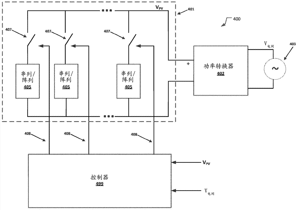
图4是带有被配置为控制光伏发电机的串列的控制器的光伏系统的框图。4 is a block diagram of a photovoltaic system with a controller configured to control a string of photovoltaic generators.
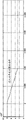
图5是在低电压穿越(LVRT)事件期间电网电压的曲线图。5 is a graph of grid voltage during a low voltage ride through (LVRT) event.
图6是由响应LVRT事件的前向反馈产生的多个连接的串列的曲线图。FIG. 6 is a graph of a series of connections resulting from feedback forward in response to an LVRT event.
图7是在断开PV串列期间PV电压的曲线图。7 is a graph of PV voltage during disconnection of a PV string.
图8是在断开PV串列期间功率吸收器电流的曲线图。8 is a graph of power sink current during disconnection of a PV string.
图9是在断开PV串列期间输入到图4所示的系统的功率吸收器的功率曲线图。9 is a graph of power input to a power absorber of the system shown in FIG. 4 during disconnection of the PV string.
图10是用于图4所示的光伏系统的控制器的框图。FIG. 10 is a block diagram of a controller for the photovoltaic system shown in FIG. 4 .
图11是用于调节图4和5所示的光伏系统的光伏发电机所提供的光伏电压的方法的流程图。11 is a flowchart of a method for regulating the photovoltaic voltage provided by the photovoltaic generator of the photovoltaic system shown in FIGS. 4 and 5 .
图12是用于调节图4和5所示的光伏系统的光伏发电机所提供的光伏电压的方法的另一个方框流程图。12 is another block flow diagram of a method for regulating a photovoltaic voltage provided by a photovoltaic generator of the photovoltaic system shown in FIGS. 4 and 5 .
图13是用于在图4中所示的光伏系统的功率逆变器的斜坡上升期间调节光伏发电机提供的电压的方法的方框流程图。13 is a block flow diagram of a method for regulating voltage provided by a photovoltaic generator during ramp-up of a power inverter of the photovoltaic system shown in FIG. 4 .
图14是可被用于实施图4所示的PV发电机的PV发电机的框图。FIG. 14 is a block diagram of a PV generator that may be used to implement the PV generator shown in FIG. 4 .
图15是可被用于实施图4所示的PV发电机的PV发电机的框图。FIG. 15 is a block diagram of a PV generator that may be used to implement the PV generator shown in FIG. 4 .
详细描述A detailed description
描述了在光伏系统中调节由光伏发电机提供的电压的技术。例如,光伏系统包括光伏发电机(本文也称之为太阳能电池阵列),其包括被布置成串列的光伏电池。可配置的串列控制器可探测光伏发电机所产生的电压应该被调节的事件并且有选择地连接或断开串列以调节光伏发电机所提供的电压。Techniques for regulating voltage provided by photovoltaic generators in photovoltaic systems are described. For example, photovoltaic systems include photovoltaic generators (also referred to herein as solar arrays) that include photovoltaic cells arranged in series. A configurable string controller can detect events in which the voltage produced by the photovoltaic generator should be regulated and selectively connect or disconnect the string to regulate the voltage provided by the photovoltaic generator.
可控串列组合器可监控PV发电机提供的功率并且确定PV发电机提供的功率的量是否超过功率吸收器的容量或PV电压是否超过功率转换器的安全电平,所述功率转换器将PV电压从DC转换成AC电流。功率吸收器可以是电网,并且可控串列组合器可以监控电网的电流容量。如果PV电压超过功率吸收器的容量和/或超过关联于功率转换器的安全电平,可控串列组合器可有选择性地断开PV电池的串列以减少PV电压。The controllable string combiner can monitor the power provided by the PV generator and determine if the amount of power provided by the PV generator exceeds the capacity of the power absorber or if the PV voltage exceeds a safe level for the power converter, which will PV voltage is converted from DC to AC current. The power sink can be a grid, and the controllable string combiner can monitor the current capacity of the grid. The controllable string combiner may selectively disconnect the string of PV cells to reduce the PV voltage if the PV voltage exceeds the capacity of the power absorber and/or exceeds a safe level associated with the power converter.
图4是光伏系统400的框图,其可被用于实施本文所述的系统和方法。光伏系统400中的PV发电机401被分成PV发电机串列405,该PV发电机串列405可被控制器49(本文也称之为可控串列组合器)9有选择性地连接或从功率转换器402断开(本文称之为逆变器)以控制PV电压。每个串列405包括一个或多个电互连的太阳能电池,而且,虽然每个标记相同,但是可以是互相不同。FIG. 4 is a block diagram of a
图14示出了PV发电机的实施例配置,其可被用于实施图4所示的PV发电机401。PV发电机包括被布置成串列的PV面板1420,每个PV面板1420包括一个或多个PV电池。每个串列可包括保险丝1405。在串列出现故障的情况下,保险丝1405可以将有故障的串列从PV系统400的剩余部分隔离开。FIG. 14 shows an example configuration of a PV generator that may be used to implement the PV generator 401 shown in FIG. 4 . The PV generator includes PV panels 1420 arranged in a series, each PV panel 1420 including one or more PV cells. Each string may include a fuse 1405 . In the event of a string failure, fuse 1405 may isolate the failed string from the rest of
串列包括一系列的电互连的PV面板1420。串列可包括PV面板的一维阵列1455,诸如阵列1455,并且多个一维阵列可组合形成二维阵列,诸如阵列1450。从功率转换器402的角度,互联的一维或二维阵列的组合表示PV发电机401。A string includes a series of electrically interconnected PV panels 1420 . A string can include a one-dimensional array 1455 of PV panels, such as array 1455 , and multiple one-dimensional arrays can be combined to form a two-dimensional array, such as array 1450 . From the perspective of the power converter 402 , the combination of interconnected one-dimensional or two-dimensional arrays represents the PV generator 401 .
图14示出了每个开关407关联于PV面板的二维阵列并且控制器499可操作开关407以连接或断开关联于该开关407的PV面板的二维阵列的实施方式。图15示出了PV发电机401的另一个实施方式,其中每个开关407关联于PV面板的一维阵列,并且控制器499可操作开关407以连接或断开关联于该开关407的PV面板的一维阵列。FIG. 14 shows an embodiment where each
每个串列可以产生的功率的量确定于实施方式。例如,包括在列内的PV面板1205的数量可以不同。例如,在一些实施中,串列产生的功率的量的范围可以是从1千瓦(kW)到3kW。PV发电机401可包括数百个单独的列。而且,1兆瓦(MW)的大型逆变器可以与包括数百个串列的PV发电机一起使用。The amount of power each string can generate is implementation dependent. For example, the number of
现在返回图4,功率转换器402将PV发电机401提供的直流(DC)功率转换成可被提供到功率吸收器403的交流AC功率。功率吸收器403可包括电力网和/或微电网提供电力的产生、存储和负载的本地化分组。例如,PV系统400可以是微电网的一部分,微电网被设计为提供电力给大学校园、工业园区或其它地方,这些地方电力的本地化分组被用于提供电力的至少一部分。Returning now to FIG. 4 , power converter 402 converts direct current (DC) power provided by PV generator 401 into alternating current AC power that can be provided to
控制器499被连接到开关407。每个开关407关联于PV发电机的串列405并且可经控制连接408被控制器499控制。控制连接408可以或者是有线连接或者无线连接,其允许控制器499发送控制信号到开关407以连接或断开关联于开关407的串列。每个开关407可以是固态继电器,其响应于经由控制连接408接收的控制信号以将关联于该开关407的串列405连接到转换器402或从转换器402断开串列405。例如,可以使用Schneider Electric生产的固态继电器来试试开关407。控制器499可以被配置为有选择性地连接或断开串列直到功率吸收器的容量或直到PV电压对于功率转换器足够的低和安全。A
虽然系统400包括三个串列405,但是可以使用不同数量的串列来构成PV发电机。PV发电机被分成的串列的数目越大,控制的粒度级别就越大,可控串列组合器499可具有控制的粒度级别以用于调节PV电压。在更细粒度的系统中,其中PV系统被分成为更大数量的可控制的列405,控制器499可通过连接或断开串列405对PV电压做出更精细的调整。与此相反,在粗粒度的实施中,其中PV发电机被分成更小数量的串列405,控制器499可通过连接或断开串列405对PV电压做出更粗的调整。Although
控制器499可被配置为监控功率吸收器403的容量并且通过暂时地从PV发电机断开多个PV电池的串列对功率吸收器的容量中的改变做出反应直到PV容量增加。控制器499也可被配置为识别和响应可能导致功率吸收器容量降低或增加由PV发电机401输出的PV电压各个类型的事件。一些实施例包括:(1)在低电压穿越(LVRT)事件期间的电网支持操作;(2)由于云边效应引起的PV功率生产过剩;以及(3)在转换器起动期间强制性的功率斜坡上升特征。这些仅仅是少数的几个事件类型的实施例,这些事件被配置为列组合器可响应这些特定事件而非被认为限制可配置的串列组合器的使用于这些特定事件。可配置的串列组合器可被配置为响应于导致PV电压和/或功率吸收器的容量改变的其它类型的事件。The
如上所述,控制器499可被配置为在LVRT事件期间调节PV电压。当电网的电压暂时地减少时发生LVRT事件。这个减少是典型地由于电网中的故障或负载的改变。在LVRT事件期间,电压可减少AC电网的一个、两个或全部三个相。当电网电压减少时,控制器499可以选择性地从PV发电机断开串列以减少PV电压。一旦LVRT事件过去,可控串列组合器可随着电网容量的恢复重新连接断开的串列。图11示出的方法可通过控制器499来实施并且可被用来响应LVRT事件。As described above, the
控制器499也可被配置为响应云边效应调节PV电压。因为随着云在空中过去太阳光到达PV发电机的量的增加,云边效应可导致PV电压的突然增加。控制器499可选择性地从PV发电机401断开串列以减少PV电压到对于电压转换器是安全的电平并且处于功率吸收器的容量内。云边效应是典型的是短暂影响,其由于云的边缘通过PV发电机401在PV电压中产生尖峰。控制器499可被配置为监控PV电压并且随着云边效应的过去重新连接一个或多个断开的串列。图12中所示的方法可由控制器499来实施并且可被用于响应由于云边效应导致的PV电压的增加。The
控制器499也可被配置为在电压转换器起动期间通过选择性地从PV发电机断开PV电池的串列以调节PV电压。电压转换器可能需要初始的起动阶段,在这个期间PV电压必定是逐渐斜坡上升。通过选择性地连接PV发电机的PV电池的串列,控制器499可逐渐斜坡升高PV电压以在起动阶段逐渐增加PV电压。图13所示的方法可通过控制器499来实施并且可被用于在逆变器起动期间逐渐斜坡升高PV电压。The
图10是可被用于实施图4示出的控制器499的串列组合控制器的框图。控制器499包括处理器1005、存储器1020、电压输入1035、电压计1030和控制接口1040。存储器1020包括电压控制模块1022、串列选择模块1024和控制信号模块1026。存储器1020可包括一类或多种类型的可接触的、非暂时的计算机可读存储器,诸如随机存取存储器(RAM)、只读存储器(ROM)、闪存或它们的组合。模块可包括可被处理器1005执行的处理器可执行的指令。FIG. 10 is a block diagram of a cascade controller that may be used to implement the
处理器1005可包括被配置为存取存储器1020的一个或多个微处理器。处理器1005可从存储器1020读数据和写数据到存储器1020。存储器1005也可从存储器1020读可执行程序代码并且执行程序代码。Processor 1005 may include one or more microprocessors configured to access memory 1020 . The processor 1005 can read data from and write data to the memory 1020 . Memory 1005 may also read executable program code from memory 1020 and execute the program code.
电压输入1035提供通过其控制器499可以监控整个光伏系统400的电压的接口。例如,电压输入1035可被用于监控电网电压(V电网)和/或PV电压(VPV),通过PV发电机产生的电压。电压计1030可被用于确定正在被监视使用电压输入1035的各种输入的电压。电压计1030可以是外部电压计并且控制器499可被配置为从监控电网电压和/或PV电压的外部电压计接收信号。The voltage input 1035 provides an interface through which the voltage of the entire
处理器1005可以经由控制接口1040发送控制信号到一个或多个外部设备。例如,控制接口1040可被连接到可被用来控制开关407的控制连接408。为了控制由PV发电机401提供的全部PV电压,控制接口1040可发送控制信号1040到关联于PV发电机401的特定串列405的开关407以连接或断开该串列。控制接口1040可被配置为提供用于经由控制连接408控制开关407的有线连接、无线连接或它们的结合。Processor 1005 may send control signals to one or more external devices via control interface 1040 . For example, control interface 1040 may be connected to control
电压控制模块1022可被配置为监控电网电压和/或PV电压以识别各种事件,诸如LVRT事件、云边效应和/或其他事件,并且通过选择性地断开或连接PV发电机的串列响应这些事件以控制PV发电机提供的电压。电压控制模块1022可被用于实施图11和12所示的方法。电压控制模块1022可被配置为做出关于一个或多个PV发电机401的串列是应该被连接还是断开的确定。为了调节PV电压,电压控制模块1022可发送命令到串列选择模块1024以断开或连接PV发电机401的一个或多个串列。The
控制信号模块1026可包括可执行的代码,该可执行的代码可导致处理器1005指示控制接口1040发送命令到一个或多个外部设备,诸如开关407。例如,控制信号模块可发送信号到开关407,指示开关407连接或断开关联于该开关的串列。控制信号模块1026可从串列选择模块1024接收命令以发送命令到一个或多个外部设备,诸如开关407。
串列选择模块1024可被配置为选择将要被连接或断开的一个或多个PV发电机401的串列以调整PV发电机401提供的PV电压。串列选择模块1024也可被配置为跟踪哪个串列当前被连接和哪个串列当前被断开。串列选择模块1024可维护串列映射存储器1020,该串列映射存储器1020指示包括PV发电机401的每个串列是连接的还是断开。串列选择模块1024可被配置为由于串列被连接或断开以调节电压而更新映射。串列选择模块也可被配置为发送命令到控制信号模块1026以连接或断开PV发电机401的一个或多个串列以调节PV电压。The
图11是用于基于电网电压控制PV发电机输出的PV电压的方法。在图11中示出的过程方法除非其他的具体规定否则可通过控制器499的电压控制模块1022来实施。当响应LVRT事件时,图11中所示的方法可被控制器499来执行。图11中所示的方法可被控制器499所使用以响应电网电压的任何变化并且并不限制于仅响应LVRT事件。Figure 11 is a method for controlling the PV voltage output by a PV generator based on the grid voltage. The process method shown in FIG. 11 may be implemented by the
电网电压可被监控以确定电网电压是否存在可能需要对PV电压进行调节的任何变化(阶段1105)。控制器499的电压控制模块1022可被配置为监控电网电压。The grid voltage may be monitored to determine if there are any changes in the grid voltage that may require regulation of the PV voltage (stage 1105). The
然后,控制器499可以做出关于电网电压是否已经减少(阶段1110)的确定。如果电网电压减少,光伏系统在PV电压中可以做出相应的减少以减少功率转换器402上的应力。The
如果电网电压减少了,电网电压相比于标称电网电压的百分比可被计算出(阶段1115)。然后,当前的电网电压可通过标称电网电压进行划分以确定标称电压与电网电压的百分比是:If the grid voltage has decreased, the percentage of the grid voltage compared to the nominal grid voltage may be calculated (stage 1115). Then, the current grid voltage can be divided by the nominal grid voltage to determine the percentage of nominal voltage to grid voltage is:
标称电压百分比=V电网/V标称 Nominal voltage percentage = V grid / V nominal
标称电压表示电网期望运行的假定的电压。某些事件,诸如LVRT事件,可导致电网电压减少到标称电压以下。Nominal voltage represents the assumed voltage at which the grid is expected to operate. Certain events, such as LVRT events, can cause the grid voltage to drop below the nominal voltage.
然后,标称电压的百分比可被用于确定许多串列被断开(阶段1117)。包括将要被断开的PV发电机401的串列数的百分比可被确定:The percentage of nominal voltage can then be used to determine how many strings are disconnected (stage 1117). The percentage of the number of strings including PV generators 401 to be disconnected can be determined:
断开的串列的百分比=100%-标称电压百分比Percentage of disconnected series = 100% - percentage of nominal voltage
例如,如果电网电压是70%的标称电压,那么电网电压少于标称电压30%。因此,PV发电机的串列的30%可被断开以减少PV电压到总的PV电压的70%。串列选择模块1024可跟踪当前多少串列是连接的或多少串列是断开的并且哪个串列是连接的或哪个串列是断开的。如果当前断开的串列的总数(N断开)少于基于电网电压的减少的应该断开的串列的总数(X断开),那么串列选择模块1024可通过从应该断开的串列的数(Xcale)减去当前断开串列的数(N断开),确定将要被断开的串列的数(S断开)。For example, if the grid voltage is 70% of the nominal voltage, then the grid voltage is less than 30% of the nominal voltage. Thus, 30% of the string of PV generators can be disconnected to reduce the PV voltage to 70% of the total PV voltage. The
S断开=X断开–N断开 S off = X off - N off
如果将要被断开的串列的数大于零,那么控制器499可发送控制信号到关联于将要被断开的串列405的开关407以使得串列将被断开(阶段1120)。串列选择模块1024可维护哪个串列被连接和哪个串列被断开的映射,并且可被配置为选择将被断开的已连接的串列,以及可更新串列的映射以反映哪个串列已被断开。被断开的串列产生的电压留在太阳能电池阵列的场中并且并不引入到转换器。一旦串列已被断开,控制器499可继续监控电网电压(阶段1105)。If the number of strings to be disconnected is greater than zero, the
如果电网电压并不减少,可做出关于电网电压是否增加(阶段1130)的确定。如果电网电压并不增加,那么控制器499可继续监控电网电压(阶段1105)。If the grid voltage is not decreasing, a determination may be made as to whether the grid voltage has increased (stage 1130). If the grid voltage is not increasing, the
否则,如果电网电压增加了,电网电压相比于标称电网电压的百分比可被计算出(阶段1135)。如上所述,然后,当前电网电压可被标称电网电压进行划分以确定标称电压与电网电压的百分比是:Otherwise, if the grid voltage has increased, the percentage of the grid voltage compared to the nominal grid voltage may be calculated (stage 1135). As mentioned above, the current grid voltage can then be divided by the nominal grid voltage to determine the percentage of nominal voltage to grid voltage as:
标称电压百分比=V电网/V标称 Nominal voltage percentage = V grid / V nominal
在LVRT事件之后或导致电网电压下降的其他事件已经过去看,电网电压可增加。控制器499可对电网电压中的这种变化做出反应,增加被连接以允许PV电压增加的串列的数量。After an LVRT event or other event causing a drop in grid voltage has passed, the grid voltage may increase. The
然后,标称电压的百分比可被用于确定将被连接的多个串列(阶段1137)。包括将要被断开的PV发电机的串列的数的百分比可被确定:The percentage of nominal voltage can then be used to determine the number of strings to be connected (stage 1137). The percentage of the number of strings comprising PV generators to be disconnected can be determined:
连接的串列的百分比=100%-标称电压百分比The percentage of connected series = 100% - nominal voltage percentage
例如,返回到以上描述的前面的实施例,如果电网电压从标称电压的70%改变到标称电压的90%,那么可被连接的PV发电机列的数目可从70%增加到90%。For example, returning to the previous embodiment described above, if the grid voltage changes from 70% of nominal voltage to 90% of nominal voltage, then the number of PV generator strings that can be connected can be increased from 70% to 90% .
串列选择模块1024可跟踪多少个串列当前被连接或多少个串列当前被断开并且哪个串列被断开或哪个串列被连接。如果当前连接的串列的总数目(N连接)少于基于电网电压的增加应当被连接(X连接)的串列的总数目,那么串列选择模块1024可通过从应当被连接的串列的数(X连接)中减去当前连接的串列的数(N连接)确定将要被断开的串列的数(S连接)。The
S连接=X连接–N连接 S connection = X connection – N connection
如果将要被连接的串列的数大于零,那么控制器499可发送控制信号到关联于串列405的开关407以导致串列被连接(阶段1140)。串列选择模块1024可指示控制信号模块1026发送控制信号到关联于将被连接的串列的开关407。串列选择模块1024可维护哪个串列被连接和哪个串列405被断开的映射,并且可被配置为选择将要被断开的已连接的串列和更新反映哪个串列已被断开的串列的映射。由断开的串列产生的电压被保留在太阳能电池阵列的场中并且并不引入到转换器。一旦串列已经被断开,控制器499可继续监控电网电压(阶段1105)。If the number of strings to be connected is greater than zero, the
图12是另一个用于控制PV发电机401输出的PV电压的方法。除非特别说明,图12中所示的方法可通过控制器499的电压控制模块1022来实施。图12中所示的方法可通过控制器499来实施并且可被用于响应由云边效应导致的PV电压的增加。图12所示的方法可被控制器499所使用以响应PV电压的任何变化并且并不限于响应云边效应。FIG. 12 is another method for controlling the PV voltage output by the PV generator 401 . Unless otherwise specified, the method shown in FIG. 12 can be implemented by the
控制器499可测量电网电压(阶段1205)。控制器499的电压控制模块1022可被配置为测量电网电压。电网电压可被用于确定参考PV电压。The
然后,控制器499可确定参考PV电压(PV参考)(阶段1210)。参考PV电压表示PV发电机401(太阳电池阵列)提供的期望的PV电压。通过测量电网电压可以确定PV电压并且基于电网电压确定PV电压。控制器499可确定期望的PV电压,该期望的PV电压将导致功率转换器402的输出具有匹配于或接近于电网电压的电压。PV电压可被预先确定并且可被存储在控制器499的存储器1020中,并且电压控制模块1022可存取存储在存储器1020的参考PV电压。The
然后,控制器499可确定当前PV电压(PV当前)正在由PV发电机401产生(阶段1215)。如上所述,控制器499的电压控制模块1022可被配置为测量PV电压。The
然后,电压控制模块1022可被配置为确定参考PV电压(PV参考)和当前PV电压(PV当前)之间的差值。The
ΔPV=PV参考–PV参考 ΔPV=PV reference – PV reference
然后,基于PV参考和PV当前之间的差值电压控制模块1022可计算将被连接或断开的串列的数目(阶段1225)。如果当前PV电压大于参考PV电压,那么ΔPV的值将是负的,指示控制器499应当断开一个或多个串列以减少当前PV电压。如果当前PV电压小于参考PV电压,那么ΔPV的值将是正的,指示控制器499应当断开一个或多个串列以增加当前PV电压。如果当前PV电压等于参考PV电压,那么ΔPV的值将是零,指示没有串列将被连接或断开。Then, based on the difference between the PV reference and the PV current , the
基于ΔPV的值,电压控制模块1022可确定多少串列应当被连接或断开。例如,ΔPV的值可通过关联于每个串列的电压产量进行划分。每个串列可被假定为产生相等的估计的PV,并且,然后ΔPV可通过估计的PV进行划分以确定多少串列应当被连接或断开。Based on the value of ΔPV, the
可选地,控制器499可被配置为测量每个串列产生的PV并且选择能够大致提供将被连接或断开的ΔPV的一个或多个串列。从每个串列产生的PV电压被测量的地方,串列选择模块可被配置为周期性地指示控制信号模块1026以测量由每个串列产生的PV,并且串列选择模块1022可存储带有连接和断开的串列的映射的这个信息。Optionally, the
然后,电压控制模块1022可基于如在阶段1225确定的将被连接或断开的串列的数目确定任何串列是否将要被断开(阶段1230)。例如,如果串列的数目是负的,那么串列的数目应当被断开,并且如果串列的数目是正的,那么串列的数目应当被连接。The
如果将被断开的串列的数目大于零,那么控制器499可发送控制信号到关联于串列405的开关407以导致串列被断开(阶段1235)。串列选择模块1024可维护哪个串列被连接和哪个列被断开的映射,并且可被配置为选择将要被断开的已连接的串列,并且更新串列的映射以反映哪个串列已被断开。被断开的串列产生的电压被留在带有太阳能电池阵列的场中并且并不引入到转换器。一旦串列已被断开,控制器499可再次确定当前PV电压(阶段1215)。If the number of strings to be disconnected is greater than zero, the
如果没有将被断开的串列,电压控制模块1022可基于如阶段1225中确定的将被连接的或断开的串列的数目确定是否断开某些串列(阶段1225)If there are no strings to be disconnected, the
如果没有将被断开的串列,那么确定串列是否将被连接(阶段1240)。如果没有串列将被连接,那么控制器499可再次确定当前PV电压(阶段1215)。If there are no strings to be disconnected, then it is determined whether strings are to be connected (stage 1240). If no strings are to be connected, the
否则,如果将被连接的串列的数目大于零,控制器499可发送控制信号到关联于串列405的开关407以导致串列被连接(阶段1245)。串列选择模块1024可维护哪个串列被连接和哪个串列被断开的映射,并且串列选择模块1024可被配置为选择将被连接的已断开的串列以更新反映哪个串列已被连接。一旦串列已被断开,那么控制器499可再次确定当前PV电压(阶段1215)。Otherwise, if the number of strings to be connected is greater than zero, the
图5-9是模拟LVRT事件并且通过串列组合控制器499响应的曲线图。图5示出了由于LVRT事件电网电压的下降的曲线图。在事件期间,电网电压下降到初始值的30%。图6提供了示出响应于图1示出的LVRT事件的控制串列数的前向反馈响应(诸如图11所示的方法)的曲线图。连接的串列的数目随着电网电压减少而减少。例如,在LVRT事件开始之前,最初有16个被连接的串列。随着电网电压持续降低串列的数目下降到6列。图7示出了随着功率吸收器(电网)的负载被移除PV电压并不过冲。图8示出了输入功率吸收器(I电网)-电网的电流。从图8可看出,随着LVRT事件继续,输入功率吸收器的电流仍然相对不变,因为控制器响应于减少的电网电压已选择性地从PV发电机断开串列。图9示出了由于PV发电机被选择性地断开,输入功率吸收器功率的减少。5-9 are graphs of simulated LVRT events and responses by the
图13是用于在光伏系统400的功率逆变器402斜破上升阶段调节光伏发电机提供的电压的方法。当功率转换器正在起动时,功率转换器402可具有强制性的功率斜坡上升期。控制器499在强制性的功率斜坡上升期可实施渐进的斜坡上升的PV功率。除非另有指示,电压控制器模块1022可实施图13示出的方法的阶段。FIG. 13 is a method for regulating the voltage provided by the photovoltaic generator during the ramp-up phase of the power inverter 402 of the
控制器499可被配置为接收逆变器起动信号,该逆变器起动信号导致控制器499渐进斜坡提升正被提供给功率转换器402的PV功率(阶段1305)。如果逆变器被打开或或重置且要求强制性的斜坡上升期,那么逆变器可被配置为发送消息到控制器499。可选地,逆变器起动信号可被已经重置功率转换器402的管理员或技师手动地提供。控制器499可包括重置键或其它接口,其允许控制器499手动地重置进入逆变器起动模式。The
然后,控制器499可通过断开关联于功率转换器402的PV起动电压的PV发电机的全部串列405,重置PV输出到PV起动电压(阶段1310)。表示PV起动电压的值可被存储在控制器499的存储器1020中并且电压控制模块1022可存取该值以确定什么样的PV起动电压应当用于什么样的具体的实施。电压控制器模块1022可发送命令到串列选择模块1024以连接用于产生PV起动电压所需的串列数并且断开超过产生PV起动电压所需的数目的任何串列。串列选择模块1024可选择将被连接和/或将被断开的串列并且发送命令到控制信号模块以连接或断开必要的串列。The
然后,控制器499可反复地连接串列以增加光伏系统400提供的PV电压直到达到期望的PV电压(阶段1315)。电压控制模块1022可被配置为在预先确定的间隔添加串列直到达到期望的PV电压。电压控制器模块可基于定义功率转换器402的斜坡上升期的持续时间计算这些增量,其可被存储在控制器499的存储器1020中并且通过电压控制模块1022进行存取。此外,在间隔期被添加的串列可至少部分地基于系统的粒度(包括PV发电机401的串列405的数目和由这些串列中的每个产生的PV电压)。期望的PV电压可使用图11和12示出的方法来确定或可基于其它因素(诸如功率吸收器的当前电压)来确定。这个反复过程提供功率转换器402时间以在起动阶段没有过载或可能损坏功率转换器402的情况下斜坡上升。The
所述的各种示出的逻辑块、模块和算法阶段可被实施为电子硬件、计算机软件或两者的结合。为了清楚的示出硬件和软件这个可交换性,各种示出的部件、方框、模块和阶段已一般地以它们的功能方面进行了以上描述。这样的功能是否被实施为硬件和软件取决于强加在整体系统的设计限制。所述的功能可以各种方式进行实施。而且,模块、方框或阶段内的功能组是出于描述方便。特定的功能可被从一个模块或方框移出而不背离本发明。The various illustrated logical blocks, modules and algorithm stages described may be implemented as electronic hardware, computer software or combinations of both. To clearly illustrate this interchangeability of hardware and software, various illustrated components, blocks, modules and stages have been described above generally in terms of their functionality. Whether such functionality is implemented as hardware or software depends upon design constraints imposed on the overall system. The described functions can be implemented in various ways. Furthermore, the grouping of functions within a module, block or stage is for convenience of description. Certain functions may be moved out from one module or block without departing from the invention.
所述的各种说明性的逻辑块和模块可被使用设计为执行本文描述的功能的通用处理器、数字信号处理器(DSP)、专用集成电路(ASIC)、现场可编程门阵列(FPGA)或其它可编程逻辑设备、离散门或晶体管逻辑、离散硬件部件或它们的任意结合来实施或执行。通用处理器可以是微处理器、但是可选地,处理器可以是任何处理器、控制器、微控制器或状态机。处理器也可被实施为计算设备的结合,例如DSP和微处理器、多个微处理器、结合DSP核的一个或多个微处理器、或任何其它这样的配置的结合。The various illustrative logic blocks and modules described can be utilized with general purpose processors, digital signal processors (DSPs), application specific integrated circuits (ASICs), field programmable gate arrays (FPGAs) designed to perform the functions described herein or other programmable logic devices, discrete gate or transistor logic, discrete hardware components, or any combination thereof. A general-purpose processor may be a microprocessor, but in the alternative, the processor may be any processor, controller, microcontroller, or state machine. A processor may also be implemented as a combination of computing devices, eg, a combination of a DSP and a microprocessor, multiple microprocessors, one or more microprocessors combined with a DSP core, or any other such configuration.
所述的方法或算法的操作可被直接实施于硬件中,处理器执行的软件模块中或两者的结合中。软件模块可驻留在RAM存储器、闪存、ROM存储器、EPROM存储器、EEPROM存储器、寄存器、硬盘、移动磁盘、CD-ROM或任何其它形式的存储介质。示例性的存储介质可被耦合到处理器使得处理器可从存储介质读信息或写信息到存储介质。可选地,存储介质可被集成到处理器。处理器和存储介质可驻留在ASIC中。The operations of the methods or algorithms described can be directly implemented in hardware, in software modules executed by a processor, or in a combination of both. A software module may reside in RAM memory, flash memory, ROM memory, EPROM memory, EEPROM memory, registers, hard disk, removable disk, CD-ROM or any other form of storage medium. An exemplary storage medium can be coupled to the processor such that the processor can read information from, and write information to, the storage medium. Optionally, a storage medium may be integrated into the processor. The processor and storage medium can reside in an ASIC.
对于以上提供的描述可做出各种变化和修改而不背离所公开内容或所附权利要求的范围。例如,尽管元件可被描述或被声明为单数,但是也可包括复数。而且,方面和/或实施方式的全部或部分可与其它方面和/或实施方式一起被使用。Various changes and modifications may be made to the description provided above without departing from the scope of the disclosure or the appended claims. For example, although an element may be described or stated as singular, the plural may also be included. Furthermore, all or part of an aspect and/or embodiment may be used with other aspects and/or embodiments.
Claims (29)
Applications Claiming Priority (3)
| Application Number | Priority Date | Filing Date | Title |
|---|---|---|---|
| US13/152,787 US9184594B2 (en) | 2011-06-03 | 2011-06-03 | Photovoltaic voltage regulation |
| US13/152,787 | 2011-06-03 | ||
| PCT/US2012/039978 WO2012166788A2 (en) | 2011-06-03 | 2012-05-30 | Photovoltaic voltage regulation |
Publications (2)
| Publication Number | Publication Date |
|---|---|
| CN103718414A true CN103718414A (en) | 2014-04-09 |
| CN103718414B CN103718414B (en) | 2016-06-01 |
Family
ID=47260279
Family Applications (1)
| Application Number | Title | Priority Date | Filing Date |
|---|---|---|---|
| CN201280038486.7A Expired - Fee Related CN103718414B (en) | 2011-06-03 | 2012-05-30 | Photovoltaic voltage regulates |
Country Status (4)
| Country | Link |
|---|---|
| US (3) | US9184594B2 (en) |
| EP (1) | EP2715905B1 (en) |
| CN (1) | CN103718414B (en) |
| WO (1) | WO2012166788A2 (en) |
Cited By (3)
| Publication number | Priority date | Publication date | Assignee | Title |
|---|---|---|---|---|
| CN105846758A (en) * | 2015-01-16 | 2016-08-10 | 台达电子工业股份有限公司 | Photovoltaic power generation system and turn-off device |
| CN107154647A (en) * | 2017-06-08 | 2017-09-12 | 阳光电源股份有限公司 | The power deratng method and controller of a kind of photovoltaic generating system |
| CN114094688A (en) * | 2020-08-24 | 2022-02-25 | 航天科工惯性技术有限公司 | MPPT redundant backup system of solar unmanned aerial vehicle and MPPT switching method |
Families Citing this family (17)
| Publication number | Priority date | Publication date | Assignee | Title |
|---|---|---|---|---|
| US9559518B2 (en) * | 2012-05-01 | 2017-01-31 | First Solar, Inc. | System and method of solar module biasing |
| US8648498B1 (en) * | 2012-11-19 | 2014-02-11 | Renewable Power Conversion, Inc | Photovoltaic power system with distributed photovoltaic string to polyphase AC power converters |
| US9929561B2 (en) * | 2013-06-26 | 2018-03-27 | Safeconnect Solar, Inc. | System and method for installing solar panels based on number of panels and output of panels |
| US9742188B2 (en) * | 2013-06-26 | 2017-08-22 | Energy Development Llc | System and method for installing solar panels based on number of panels and output of panels |
| US10367357B2 (en) | 2013-06-26 | 2019-07-30 | Safeconnect Solar, Inc. | System and method for installing solar panels |
| US20150288188A1 (en) * | 2014-04-08 | 2015-10-08 | Marvin S Keshner | Parallel-Connected Solar Electric System |
| US9847751B2 (en) * | 2014-07-30 | 2017-12-19 | International Business Machines Corporation | Techniques for optimizing photo-voltaic power via inductive coupling |
| CN104821599B (en) * | 2015-05-14 | 2017-04-12 | 国家电网公司 | Control method for improving photovoltaic low voltage ride through capacity based on current feedback |
| CA2990619C (en) | 2015-08-18 | 2022-03-15 | Argentum Electronics, Inc. | Wide range power combiner |
| US10374424B2 (en) | 2015-08-18 | 2019-08-06 | Argentum Electronics, Inc. | Wide range power distribution systems and methods |
| CN106526347B (en) * | 2015-09-14 | 2019-08-06 | 中国电力科学研究院 | A kind of low voltage ride through of photovoltaic inverter appraisal procedure based on numerical model analysis emulation |
| DE102015222210A1 (en) | 2015-11-11 | 2017-05-11 | Siemens Aktiengesellschaft | Method, forecasting device and control device for controlling a power grid with a photovoltaic system |
| JP6626188B2 (en) * | 2016-02-25 | 2019-12-25 | 株式会社東芝 | Grid connection equipment |
| FR3074611B1 (en) * | 2017-12-01 | 2021-12-03 | Commissariat Energie Atomique | SYSTEM AND METHOD FOR RECONNECTING A CHAIN IN A PHOTOVOLTAIC POWER PLANT |
| CN110391671B (en) * | 2018-04-23 | 2023-03-10 | 台达电子工业股份有限公司 | Optimizer, control method and parallel structure for photovoltaic inverter system |
| EP3772757A1 (en) * | 2019-08-07 | 2021-02-10 | Solaredge Technologies Ltd. | Solar panel arrangement |
| EP3846337B1 (en) * | 2019-12-30 | 2025-09-10 | Solaredge Technologies Ltd. | Energy harvesting and electrical power generation |
Citations (5)
| Publication number | Priority date | Publication date | Assignee | Title |
|---|---|---|---|---|
| JPH07177652A (en) * | 1993-12-17 | 1995-07-14 | Canon Inc | Photovoltaic system and protection method for photovoltaic system |
| US20010023703A1 (en) * | 2000-02-29 | 2001-09-27 | Hiroshi Kondo | Solar power generation apparatus and control method therefor |
| CN101636847A (en) * | 2006-12-06 | 2010-01-27 | 太阳能安吉有限公司 | Monitoring of distributed power harvesting systems using DC power sources |
| WO2010078303A2 (en) * | 2008-12-29 | 2010-07-08 | Atonometrics, Inc. | Electrical safety shutoff system and devices for photovoltaic modules |
| US20110025130A1 (en) * | 2009-07-30 | 2011-02-03 | Tigo Energy, Inc. | Systems and method for limiting maximum voltage in solar photovoltaic power generation systems |
Family Cites Families (15)
| Publication number | Priority date | Publication date | Assignee | Title |
|---|---|---|---|---|
| US20030066555A1 (en) * | 2000-12-04 | 2003-04-10 | Hui Ron Shu Yuen | Maximum power tracking technique for solar panels |
| EP2145374B1 (en) * | 2007-05-08 | 2014-03-19 | American Power Conversion Corporation | Alternative-source energy management |
| US9048353B2 (en) * | 2008-07-01 | 2015-06-02 | Perfect Galaxy International Limited | Photovoltaic DC/DC micro-converter |
| EP2219276B1 (en) * | 2009-02-11 | 2015-12-02 | SMA Solar Technology AG | Photovoltaic assembly for three-phase feeding into an electric energy supply network |
| EP2282388A1 (en) * | 2009-08-06 | 2011-02-09 | SMA Solar Technology AG | Device for feeding in electrical energy of a number of strings of photovoltaic modules in an electricity network |
| ATE555531T1 (en) * | 2009-08-06 | 2012-05-15 | Sma Solar Technology Ag | RETURN CURRENT SENSOR FOR PARALLEL CONNECTED SOLAR MODULES |
| US8263920B2 (en) * | 2009-09-30 | 2012-09-11 | The Boeing Company | Diodeless terrestrial photovoltaic solar power array |
| US8334618B2 (en) * | 2009-11-13 | 2012-12-18 | Eaton Corporation | Method and area electric power system detecting islanding by employing controlled reactive power injection by a number of inverters |
| EP2325984A1 (en) | 2009-11-24 | 2011-05-25 | SMA Solar Technology AG | Start up of a photovoltiac field with high open circuit voltage |
| US8624561B1 (en) * | 2009-12-29 | 2014-01-07 | Solarbridge Technologies, Inc. | Power conversion having energy storage with dynamic reference |
| US8355265B2 (en) * | 2010-03-14 | 2013-01-15 | Mechanical Electrical Systems, Inc. | DC-to-DC power conversion |
| DE102010017747A1 (en) * | 2010-05-03 | 2011-11-03 | Sma Solar Technology Ag | Method for limiting the generator voltage of a photovoltaic system in case of danger and photovoltaic system |
| US10847972B2 (en) * | 2010-09-23 | 2020-11-24 | Hybridyne Power Electronics Inc. | Method and system for optimizing power generated by a photovoltaic system |
| US8446042B2 (en) * | 2010-11-30 | 2013-05-21 | Ideal Power Converters, Inc. | Photovoltaic array systems, methods, and devices with improved diagnostics and monitoring |
| US10003200B2 (en) | 2016-01-04 | 2018-06-19 | Schneider Electric It Corporation | Decentralized module-based DC data center |
-
2011
- 2011-06-03 US US13/152,787 patent/US9184594B2/en not_active Expired - Fee Related
-
2012
- 2012-05-30 WO PCT/US2012/039978 patent/WO2012166788A2/en not_active Ceased
- 2012-05-30 EP EP12792092.4A patent/EP2715905B1/en active Active
- 2012-05-30 CN CN201280038486.7A patent/CN103718414B/en not_active Expired - Fee Related
-
2015
- 2015-09-30 US US14/870,306 patent/US9941701B2/en not_active Expired - Fee Related
-
2018
- 2018-04-09 US US15/948,377 patent/US10305285B2/en not_active Expired - Fee Related
Patent Citations (5)
| Publication number | Priority date | Publication date | Assignee | Title |
|---|---|---|---|---|
| JPH07177652A (en) * | 1993-12-17 | 1995-07-14 | Canon Inc | Photovoltaic system and protection method for photovoltaic system |
| US20010023703A1 (en) * | 2000-02-29 | 2001-09-27 | Hiroshi Kondo | Solar power generation apparatus and control method therefor |
| CN101636847A (en) * | 2006-12-06 | 2010-01-27 | 太阳能安吉有限公司 | Monitoring of distributed power harvesting systems using DC power sources |
| WO2010078303A2 (en) * | 2008-12-29 | 2010-07-08 | Atonometrics, Inc. | Electrical safety shutoff system and devices for photovoltaic modules |
| US20110025130A1 (en) * | 2009-07-30 | 2011-02-03 | Tigo Energy, Inc. | Systems and method for limiting maximum voltage in solar photovoltaic power generation systems |
Cited By (5)
| Publication number | Priority date | Publication date | Assignee | Title |
|---|---|---|---|---|
| CN105846758A (en) * | 2015-01-16 | 2016-08-10 | 台达电子工业股份有限公司 | Photovoltaic power generation system and turn-off device |
| CN107154647A (en) * | 2017-06-08 | 2017-09-12 | 阳光电源股份有限公司 | The power deratng method and controller of a kind of photovoltaic generating system |
| CN107154647B (en) * | 2017-06-08 | 2020-05-22 | 阳光电源股份有限公司 | Power derating method and controller of photovoltaic power generation system |
| CN114094688A (en) * | 2020-08-24 | 2022-02-25 | 航天科工惯性技术有限公司 | MPPT redundant backup system of solar unmanned aerial vehicle and MPPT switching method |
| CN114094688B (en) * | 2020-08-24 | 2023-09-08 | 航天科工惯性技术有限公司 | MPPT redundant backup system and MPPT switching method of solar unmanned aerial vehicle |
Also Published As
| Publication number | Publication date |
|---|---|
| US20180358811A1 (en) | 2018-12-13 |
| EP2715905A4 (en) | 2015-07-01 |
| EP2715905B1 (en) | 2019-09-04 |
| EP2715905A2 (en) | 2014-04-09 |
| US9184594B2 (en) | 2015-11-10 |
| WO2012166788A2 (en) | 2012-12-06 |
| US9941701B2 (en) | 2018-04-10 |
| US10305285B2 (en) | 2019-05-28 |
| US20120306279A1 (en) | 2012-12-06 |
| WO2012166788A3 (en) | 2013-02-28 |
| CN103718414B (en) | 2016-06-01 |
| US20160020611A1 (en) | 2016-01-21 |
Similar Documents
| Publication | Publication Date | Title |
|---|---|---|
| CN103718414B (en) | Photovoltaic voltage regulates | |
| JP5162043B1 (en) | Charger | |
| CN107154647B (en) | Power derating method and controller of photovoltaic power generation system | |
| EP3823152A1 (en) | Power conversion system, conversion circuit control method and program | |
| CN110915090A (en) | Method and system for extracting excess power | |
| KR101830666B1 (en) | Power conversion apparatus | |
| WO2013010129A2 (en) | Customized electric power storage device for inclusion in a microgrid | |
| JPWO2015029138A1 (en) | Solar power system | |
| CN104079001A (en) | Optimizer control method based on series-type optimizers in photovoltaic grid-connected system | |
| US11329488B2 (en) | Power conversion system, method for controlling converter circuit, and program | |
| CA2937802C (en) | Method and apparatus for extracting electrical energy from photovoltaic module | |
| JP2005269843A (en) | Parallel operation device | |
| JP5601912B2 (en) | Control device for power converter, and grid-connected inverter system using this control device | |
| WO2014047560A1 (en) | Serially connected micro-inverter system having concertina output voltage control | |
| JP5985000B2 (en) | Method for supplying energy from a photovoltaic module of a photovoltaic system and an inverter designed to perform the method | |
| CN106786803A (en) | Independent operating photovoltaic generating system is for more than a kind of lossless power-balance method for taking | |
| US10523014B2 (en) | Control of a multiple input solar power inverter | |
| Mazhari et al. | Distributed PV-battery architectures with reconfigurable power conversion units | |
| JP2017077124A (en) | Power storage device | |
| CN113366404A (en) | Power system and power conversion device | |
| EP2544329B1 (en) | Method and arrangement for connecting a plurality of solar panel units to an inverter | |
| CN102957165A (en) | Renewable energy output monitoring | |
| JP2018081621A (en) | Power control apparatus and power control method thereof | |
| Poovitha et al. | Automatic Power Supply for Residential Consumer Using Microgrid with Hybrid Power Supply |
Legal Events
| Date | Code | Title | Description |
|---|---|---|---|
| C06 | Publication | ||
| PB01 | Publication | ||
| C10 | Entry into substantive examination | ||
| SE01 | Entry into force of request for substantive examination | ||
| C14 | Grant of patent or utility model | ||
| GR01 | Patent grant | ||
| CF01 | Termination of patent right due to non-payment of annual fee |
Granted publication date: 20160601 Termination date: 20210530 |
|
| CF01 | Termination of patent right due to non-payment of annual fee |