CN103674080A - Optical fiber interference method and system aimed at weak signal detection - Google Patents
Optical fiber interference method and system aimed at weak signal detection Download PDFInfo
- Publication number
- CN103674080A CN103674080A CN201310698568.0A CN201310698568A CN103674080A CN 103674080 A CN103674080 A CN 103674080A CN 201310698568 A CN201310698568 A CN 201310698568A CN 103674080 A CN103674080 A CN 103674080A
- Authority
- CN
- China
- Prior art keywords
- phase
- optical fiber
- interference
- signal
- fiber
- Prior art date
- Legal status (The legal status is an assumption and is not a legal conclusion. Google has not performed a legal analysis and makes no representation as to the accuracy of the status listed.)
- Pending
Links
Images


Landscapes
- Instruments For Measurement Of Length By Optical Means (AREA)
Abstract
本发明属于光纤传感技术领域,具体为一种针对微弱信号检测的光纤干涉方法及系统。本发明通过在干涉系统中引入相位调制器,在被测微弱信号带宽以外的某一频率引入大幅度的相位调制信号,间接使微弱信号达到发明装置的满幅,从而满足了基于

The invention belongs to the technical field of optical fiber sensing, in particular to an optical fiber interference method and system for weak signal detection. The present invention introduces a phase modulator into the interference system, introduces a large-amplitude phase modulation signal at a certain frequency outside the bandwidth of the weak signal to be measured, and indirectly makes the weak signal reach the full amplitude of the inventive device, thereby satisfying the requirements based on
Description
技术领域technical field
本发明属于光纤传感技术领域,具体涉及一种针对微弱信号检测的光纤干涉系统。The invention belongs to the technical field of optical fiber sensing, and in particular relates to an optical fiber interference system for weak signal detection.
背景技术Background technique
维护基础设施的安全是社会稳定,经济快速发展的一个基本要求。当前,我国对于油气管道,电网等基础设施的监测主要依据设施自身的一些生产参数(压力突降,中间站油罐液位的不正常变化)和人工巡视,路人的报告等手段。这些手段技术含量低,普遍存在效率低,实时性差,反应时间长,抗干扰能力差等缺陷,常常是监测设施遭到破坏后才能报警,实用性受自然和人为双重因素的制约。这种“亡羊补牢式”的事后检测技术,只可能减少而不能避免损失。特别是受电磁干扰的影响,对长距离管线的监测,不可能实施可靠电的方式进行传感监测。因此,光纤传感技术将成为进行电力,油气管道等行业的安全监测的主要技术手段。Maintaining the security of infrastructure is a basic requirement for social stability and rapid economic development. At present, my country's monitoring of infrastructure such as oil and gas pipelines and power grids is mainly based on some production parameters of the facilities themselves (pressure drop, abnormal changes in the liquid level of oil tanks in intermediate stations), manual inspections, and reports from passers-by. These methods are low in technical content, generally have defects such as low efficiency, poor real-time performance, long response time, and poor anti-interference ability. Usually, the alarm can only be called after the monitoring facilities are damaged, and the practicability is restricted by both natural and human factors. This "remedial" post-event detection technology can only reduce but not avoid losses. Especially affected by electromagnetic interference, it is impossible to implement reliable electrical sensor monitoring for long-distance pipeline monitoring. Therefore, optical fiber sensing technology will become the main technical means for safety monitoring in industries such as electric power and oil and gas pipelines.
对于干涉型光纤传感器,其基本的传感机理是,在待测场能量的作用下,使光纤中传播的光波发生相位变化,再以干涉测量技术把相位变化转换为振幅变化,实现待测物理量的测量。正由于采用了干涉技术,在实际应用中,必须首先采用适当的信号处理技术将外界扰动引起的相位差信号从干涉信号中提取出来。目前,应用较多的是基于3×3耦合器相位调制和解调技术进行的相位检测方法。For interferometric fiber optic sensors, the basic sensing mechanism is that under the action of the energy of the field to be measured, the phase change of the light wave propagating in the fiber occurs, and then the phase change is converted into an amplitude change by interferometric technology to realize the physical quantity to be measured. Measurement. Because of the use of interference technology, in practical applications, the phase difference signal caused by external disturbance must be extracted from the interference signal by using appropriate signal processing technology first. At present, the phase detection method based on 3×3 coupler phase modulation and demodulation technology is widely used.
图1是一种基于3×3耦合器相位调制和解调的分布式光纤传感系统。图1中,干涉光源,光纤干涉组件,反馈装置,探测器及信号处理单元构成该光纤传感系统。光纤干涉组件由第一光纤分路器,光纤延迟线,第二光纤分路器连接组成。其中,第一光纤分路器是一个3×3光纤耦合器,光从光纤干涉组件的3×3耦合器的一端口输入,亦从干涉组件的3×3耦合器的其他端口和输出,并最终进入探测器及信号处理单元。Figure 1 is a distributed optical fiber sensing system based on 3×3 coupler phase modulation and demodulation. In Fig. 1, an interference light source, an optical fiber interference component, a feedback device, a detector and a signal processing unit constitute the optical fiber sensing system. The optical fiber interference component is composed of a first optical fiber splitter, an optical fiber delay line, and a second optical fiber splitter. Wherein, the first optical fiber splitter is a 3×3 fiber optic coupler, the light is input from one port of the 3×3 coupler of the optical fiber interference component, and is also output from other ports of the 3×3 coupler of the interference component, and Finally enter the detector and signal processing unit.
图2为另一种采用3×3耦合器进行相位调制和解调的基于波分复用技术的光纤分布式监测定位干涉系统。其采用波分复用的技术,使得如图1所示的两个不同波长的干涉系统可以复用光源,光纤干涉组件和传感光纤。通过基于3×3耦合器的信号解调算法,使同一扰动获得两个不同的相位差信号。图2中,干涉系统由干涉光源,光纤干涉组件,感应光纤,反馈装置,探测器及信号处理单元构成。光纤干涉组件由第一光纤分路器,光纤延迟线和第二光纤分路器连接组成。其中,第一光纤分路器是一个3×3光纤耦合器。第二光纤分路器是一2×2光纤耦合器,反馈装置由第一波分复用器,第一光纤,第一反射装置,第二光纤和第二反射装置构成。其中第一波分复用器为一波分复用器。因此,光纤干涉组件和感应光纤,第一波分复用器,第一光纤和第一反射装置共同形成光波λ1的干涉光路;光纤干涉组件和感应光纤,第一波分复用器,第二光纤和第二反馈装置共同形成光波λ2的干涉光路。光从光纤干涉组件的3×3耦合器的一端口输入,亦从干涉组件的3×3耦合器的其它端口输出,分别进入第二波分复用器和第三波分复用器,并最终进入探测器及信号处理单元。Figure 2 is another optical fiber distributed monitoring and positioning interference system based on wavelength division multiplexing technology using 3×3 couplers for phase modulation and demodulation. It adopts wavelength division multiplexing technology, so that two interference systems with different wavelengths as shown in Figure 1 can multiplex light sources, optical fiber interference components and sensing optical fibers. Through the signal demodulation algorithm based on 3×3 coupler, two different phase difference signals can be obtained from the same disturbance. In Fig. 2, the interference system is composed of an interference light source, an optical fiber interference component, a sensing optical fiber, a feedback device, a detector and a signal processing unit. The optical fiber interference component is composed of a first optical fiber splitter, a fiber delay line and a second optical fiber splitter connection. Wherein, the first fiber splitter is a 3×3 fiber coupler. The second optical fiber splitter is a 2×2 optical fiber coupler, and the feedback device is composed of a first wavelength division multiplexer, a first optical fiber, a first reflection device, a second optical fiber and a second reflection device. Wherein the first wavelength division multiplexer is a wavelength division multiplexer. Therefore, the optical fiber interference component and the sensing fiber, the first wavelength division multiplexer, the first optical fiber and the first reflection device jointly form the interference optical path of the light wave λ1 ; the optical fiber interference component and the sensing fiber, the first wavelength division multiplexer, the first wavelength division multiplexer The two optical fibers and the second feedback device jointly form the interference optical path of the light wave λ2 . The light is input from one port of the 3×3 coupler of the optical fiber interference component, and is also output from other ports of the 3×3 coupler of the interference component, enters the second wavelength division multiplexer and the third wavelength division multiplexer respectively, and Finally enter the detector and signal processing unit.
对于图1或图2所示干涉系统,通过基于3×3耦合器的相位调制和解调的方法,可以将相位信号从干涉信号中恢复出来,从而获得外界扰动信息。在相位解调的过程中,直流补偿和归一化过程均需要满足外界扰动信号达到干涉仪的满幅的要求。对于无法满足该要求的微弱信号,就无法对其进行准确的相位解调,从而导致扰动位置的错误判断,使系统的测量能力受到了限制。同时,考虑到3×3耦合器无法满足对称结构,即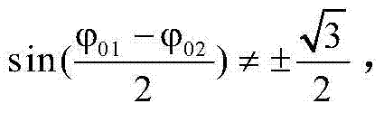
发明内容Contents of the invention
为了克服现有技术的不足,本发明的目的在于提供一种针对微弱信号检测的光纤干涉方法及系统。其是通过在系统中引入相位调制器,从而在被测微弱信号带宽以外的某一频率引入大幅度的相位调制信号,实现对微弱信号的检测的目的,其工作状态稳定,同时定位精度高。In order to overcome the shortcomings of the prior art, the object of the present invention is to provide an optical fiber interference method and system for weak signal detection. By introducing a phase modulator into the system, a large-amplitude phase modulation signal is introduced at a frequency outside the bandwidth of the weak signal to be measured to achieve the purpose of detecting weak signals. Its working state is stable and its positioning accuracy is high.
本发明提供的一种针对微弱信号检测的光纤干涉方法,其采用改进的基于3×3耦合器的相位还原算法,获得外界扰动引起的相位差信号,具体步骤如下:An optical fiber interference method for weak signal detection provided by the present invention uses an improved phase restoration algorithm based on a 3×3 coupler to obtain a phase difference signal caused by external disturbances, and the specific steps are as follows:
(1)在干涉系统中引入相位调制器,并在该相位调制器上加载大幅度的相位信号φcos(ωt),使干涉信号达到干涉系统的满幅。(1) Introduce a phase modulator into the interference system, and load a large-amplitude phase signal φcos(ωt) on the phase modulator, so that the interference signal reaches the full range of the interference system.
(2)当监控线路D处有微弱信号扰动时,那么在光接收端产生具有一定相位差的干涉信号,经过光电转换及直流滤除后,探测器及信号处理单元探测到的干涉信号的交流分量分别为:(2) When there is a weak signal disturbance at the monitoring line D, an interference signal with a certain phase difference is generated at the optical receiving end. After photoelectric conversion and DC filtering, the AC of the interference signal detected by the detector and the signal processing unit The components are:

上式中,A(t),B(t)为经两路放大器分别放大后所产生的幅度系数,φcos(ωt)为载波信号,
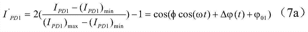
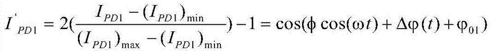
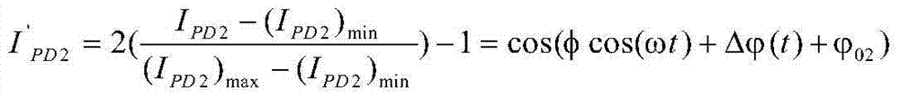
由于载波信号φcos(ωt)的变化达到干涉系统的满幅,因此可以准确地获得IPD1和IPD2的最大值(IPD1)max,(IPD2)max和最小值(IPD1)min,(IPD2)min,从而可以准确的对干涉信号进行直流补偿和归一化,继而得到:Since the change of the carrier signal φcos(ωt) reaches the full scale of the interference system, the maximum value (I PD1 ) max , (I PD2 ) max and the minimum value (I PD1 ) min of I PD1 and I PD2 can be accurately obtained, ( I PD2 ) min , so that the DC compensation and normalization of the interference signal can be accurately performed, and then:

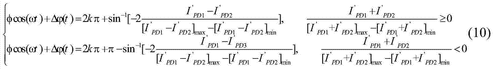
由此可以算出一个周期内的相位:From this the phase within a cycle can be calculated:
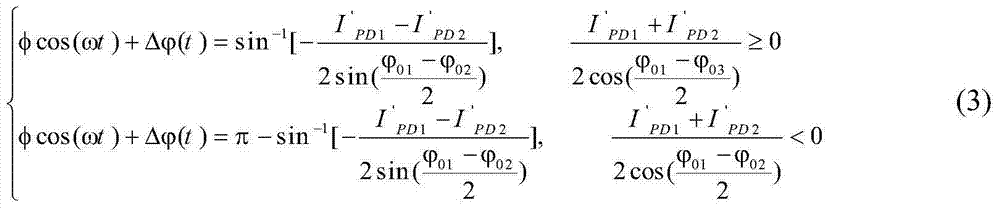
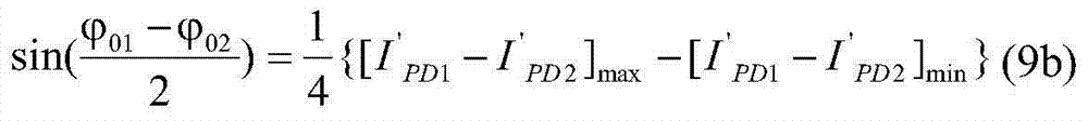
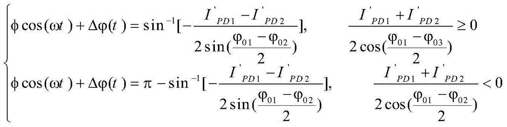
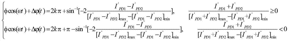
(3)对
其中:[I'PD1-I'PD2]max和[I'PD1-I'PD2]min分别为I'PD1-I'PD2的最大值和最小值Where: [I' PD1 -I' PD2 ] max and [I' PD1 -I' PD2 ] min are the maximum and minimum values of I' PD1 -I' PD2 respectively
因此,经过以上改进的基于3×3耦合器的相位还原算法获得的相位信号

(4)将该相位还原后得到的高频信号
本发明还提供了一种针对微弱信号检测的光纤干涉系统,其包括干涉光源、光纤干涉组件,相位调制器、反馈装置和探测器及信号处理单元;所述光纤干涉组件由第一光纤分路器、光纤延迟线和第二光纤分路器连接组成,所述第一光纤分路器是3×3光纤耦合器,第二光纤分路器是2×2光纤耦合器;其中:当所述反馈装置由反射装置单独构成时,在所述光纤干涉组件和反馈装置之间的感应光纤上串接相位调制器;当所述反馈装置由一波分复用器通过第一光纤和第二光纤分别连接两个反射装置而构成时,在所述光纤干涉组件和反馈装置之间的感应光纤上串接相位调制器,或者在第一光纤和第二光纤上分别串接相位调制器,所述相位调制器上所加载的相位信号达到干涉系统的满幅,实现对相位信号的准确解调。The present invention also provides an optical fiber interference system for weak signal detection, which includes an interference light source, an optical fiber interference assembly, a phase modulator, a feedback device, a detector, and a signal processing unit; the optical fiber interference assembly is branched by a first optical fiber device, a fiber delay line and a second fiber splitter, the first fiber splitter is a 3×3 fiber coupler, and the second fiber splitter is a 2×2 fiber coupler; wherein: when the When the feedback device is composed of a reflection device alone, a phase modulator is connected in series on the induction fiber between the optical fiber interference assembly and the feedback device; when the feedback device is composed of a wavelength division multiplexer through the first optical fiber and the second optical fiber When two reflection devices are respectively connected, a phase modulator is connected in series on the sensing fiber between the optical fiber interference component and the feedback device, or a phase modulator is connected in series on the first optical fiber and the second optical fiber respectively, and the The phase signal loaded on the phase modulator reaches the full scale of the interference system, so as to realize accurate demodulation of the phase signal.
本发明的有益效果在于:本发明系统结构简单,它根据微弱信号的特点,对相位解调进行改进,消除了检测信号微弱带来的无法检测定位的问题,大大提高了光纤分布式干涉系统的普适性。并且工作状态稳定,定位精度高。该光纤干涉系统可广泛应用于电力传输线,天然气管道和石油管道的安全监测领域;也可以应用于大型建筑物例如水坝,隧道,矿井等的安全监测。The beneficial effects of the present invention are: the system structure of the present invention is simple, it improves the phase demodulation according to the characteristics of the weak signal, eliminates the problem of inability to detect and locate caused by the weak detection signal, and greatly improves the performance of the optical fiber distributed interference system. universality. And the working state is stable and the positioning accuracy is high. The optical fiber interference system can be widely used in the field of safety monitoring of power transmission lines, natural gas pipelines and oil pipelines; it can also be used in the safety monitoring of large buildings such as dams, tunnels, mines, etc.
附图说明Description of drawings
图1为基于3×3耦合器相位调制和解调的分布式光纤传感系统示意图。Figure 1 is a schematic diagram of a distributed optical fiber sensing system based on 3×3 coupler phase modulation and demodulation.
图2为采用3×3耦合器进行相位调制和解调的基于波分复用技术的光纤分布式监测定位干涉系统示意图。Fig. 2 is a schematic diagram of an optical fiber distributed monitoring and positioning interference system based on wavelength division multiplexing technology using a 3×3 coupler for phase modulation and demodulation.
图3为本发明中改进的分布式光纤定位干涉系统示意图。Fig. 3 is a schematic diagram of the improved distributed optical fiber positioning interference system in the present invention.
图4为本发明中改进的基于波分复用的一种光纤定位干涉系统示意图。Fig. 4 is a schematic diagram of an improved optical fiber positioning interference system based on wavelength division multiplexing in the present invention.
图5为本发明中改进的基于波分复用的另一种光纤定位干涉系统示意图。Fig. 5 is a schematic diagram of another optical fiber positioning interference system improved based on wavelength division multiplexing in the present invention.
图中标号:1-第一光纤分路器;2-第二光纤分路器;3-光纤延迟线;4-感应光纤;5-反馈装置;6-光纤干涉组件;7-探测器及信号处理单元;8-干涉光源;9-波分复用器;10-第一光纤;11-第一反射装置;12-第二光纤;13-第二反射装置;14-第一相位调制器;15-第二相位调制器;16-第三相位调制器;17-第四相位调制器。Labels in the figure: 1-first fiber splitter; 2-second fiber splitter; 3-fiber delay line; 4-sensing fiber; 5-feedback device; 6-fiber interference component; 7-detector and signal Processing unit; 8-interference light source; 9-wavelength division multiplexer; 10-first optical fiber; 11-first reflecting device; 12-second optical fiber; 13-second reflecting device; 14-first phase modulator; 15 - second phase modulator; 16 - third phase modulator; 17 - fourth phase modulator.
具体实施方式Detailed ways
下面结合附图和实施例对本发明进一步详细说明。The present invention will be described in further detail below in conjunction with the accompanying drawings and embodiments.
实施例1Example 1
如图3所示是本发明中改进的分布式光纤定位干涉系统示意图。其系统是基于图1所示分布式光纤传感系统进行改进得到。Fig. 3 is a schematic diagram of the improved distributed optical fiber positioning interference system in the present invention. Its system is improved based on the distributed optical fiber sensing system shown in Figure 1.
干涉光源8,光纤干涉组件6,反馈装置5和探测器及信号处理单元7构成该光纤传感系统。光纤干涉组件6由第一光纤分路器1,光纤延迟线3和第二光纤分路器2连接组成。其中,第一光纤分路器1是一个3×3光纤耦合器,1a,1b,1c是第一光纤分路器1的同向端口,1d,1f属另一组同向端口。第二光纤分路器2是一个2×2光纤耦合器,2c,2d是第二光纤分路器2的一组同向端口,2a属另一组同向端口。光从光纤干涉组件6的3×3耦合器1的端口1a输入,亦从干涉组件11的3×3耦合器1的端口1b和1c输出,并最终进入探测器及信号处理单元7。An interference
本实施例中,在感应光纤4任意位置上串接第一相位调制器14,可以在外界微弱扰动信号带宽以外的某一频率引入大幅度的相位调制信号,间接使微弱信号达到发明装置的满幅。In this embodiment, the
上述改进的分布式光纤定位干涉系统存在的干涉光的传输路径为:干涉光源8通过第一光纤分路器1的端口1a进入光纤干涉组件6。在光纤干涉组件6中,光被分为顺时针传播和逆时针传播的两束光,其中顺时针传播的光从第一光纤分路器1的端口1a经过光纤延迟线3(TDF1)到达第二光纤分路器2的端口2c,逆时针传播的光从第一光纤分路器1的端口1f到达第二光纤分路器2的端口2d。这两束光同时从第二光纤分路器2的端口2a,通过第一相位调制器14进入感应光纤4。在感应光纤的尾端,通过由法拉第旋转镜构成的反馈装置5。经反馈装置5反射的光重新注入感应光纤4和光纤干涉组件6,并在第一光纤分路器1发生干涉。The transmission path of the interference light existing in the above-mentioned improved distributed optical fiber positioning interference system is: the interference
图4、图5为经改进后的基于图2所示的波分复用技术的光纤分布式监测定位干涉系统。Figure 4 and Figure 5 are the improved optical fiber distributed monitoring and positioning interference system based on the wavelength division multiplexing technology shown in Figure 2 .
图4、图5中,系统由干涉光源8,光纤干涉组件6,第二相位调制器15,感应光纤4,反馈装置5,探测器及信号处理单元7构成。光纤干涉组件6由第一光纤分路器1,光纤延迟线3,第二光纤分路器2连接组成。其中,第一光纤分路器1是一个3×3光纤耦合器,1a,1b,1c是第一光纤分路器1的同向端口,1d,1f属另一组同向端口。第二光纤分路器2是一2×2光纤耦合器,2c,2d是第二光纤分路器2的一组同向端口,2a属另一组同向端口。反馈装置12由波分复用器9,第一光纤10,第一反射装置11,第二光纤12和第二反射装置13构成。其中波分复用器9为一波分复用器,9a使其复用波长端口,9b和9c是其独立波长端口。因此,光纤干涉组件6和感应光纤4,波分复用器9,第一光纤10,第一反射装置11共同形成光波λ1的干涉光路;光纤干涉组件6和感应光纤4,波分复用器9,第二光纤12,第二反馈装置13共同形成光波λ2的干涉光路。光从光纤干涉组件6输入,亦从光纤干涉组件6的端口1b和1c输出,进入探测器及信号处理单元7。本发明中,进一步的,通过在感应光纤4的任意位置上串接第二相位调制器15(图4);或者在反馈装置5中第一光纤10和第二光纤12任意位置处分别串接第三相位调制器16和第四相位调制器17(图5),使得被测微弱信号带宽以外的某一频率引入大幅度的相位调制信号,间接使在监控线路上扰动点D上施加的微弱信号达到发明装置的满幅。In Fig. 4 and Fig. 5, the system is composed of an interference
本发明是通过采用以下提出的基于3×3耦合器的相位还原算法,获得外界扰动引起的相位差信号。即:The present invention obtains the phase difference signal caused by the external disturbance by adopting the phase restoration algorithm based on the 3×3 coupler proposed below. Right now:
在干涉系统中引入相位调制器,并在该相位调制器上加载的大幅度的相位信号φcos(ωt),使干涉信号达到干涉系统的满幅。当监控线路D处有微弱信号扰动时,那么在光接收端产生的具有一定相位差的干涉信号,经过光电转换及直流滤除后,探测器及信号处理单元探测到的干涉信号的交流分量分别为:A phase modulator is introduced into the interference system, and a large-amplitude phase signal φcos(ωt) is loaded on the phase modulator to make the interference signal reach the full scale of the interference system. When there is a weak signal disturbance at the monitoring line D, the interference signal with a certain phase difference generated at the optical receiving end, after photoelectric conversion and DC filtering, the AC components of the interference signal detected by the detector and the signal processing unit are respectively for:


上式中,A(t),B(t)为经两路放大器分别放大后所产生的幅度系数,φcos(ωt)为载波信号,

由于载波信号φcos(ωt)的变化达到干涉系统的满幅,因此可以准确地获得IPD1和IPD2的最大值(IPD1)max,(IPD2)max和最小值(IPD1)min,(IPD2)min,从而可以准确的对干涉信号进行直流补偿和归一化,继而得到:Since the change of the carrier signal φcos(ωt) reaches the full scale of the interference system, the maximum value (I PD1 ) max , (I PD2 ) max and the minimum value (I PD1 ) min of I PD1 and I PD2 can be accurately obtained, ( I PD2 ) min , so that the DC compensation and normalization of the interference signal can be accurately performed, and then:

由此可以算出一个周期内的相位:From this the phase within a cycle can be calculated:

上式中,当3×3耦合器为对称结构时,


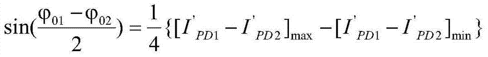
当φcos(ωt)的变化达到干涉系统的满幅时,由三角函数的性质可知,I'PD1-I'PD2的最大值和最小值分别为:[I'PD1-I'PD2]max和[I'PD1-I'PD2]min。由此可得When the change of φcos(ωt) reaches the full range of the interference system, it can be seen from the properties of trigonometric functions that the maximum and minimum values of I' PD1 -I' PD2 are: [I' PD1 -I' PD2 ] max and [ I' PD1 -I' PD2 ] min . Therefore
由式(10b)可以准确的对3×3耦合器进行初始相位计算。By formula (10b) can accurately calculate the initial phase of the 3 × 3 coupler.
因此,经过以上改进的基于3×3耦合器的相位还原算法获得的相位信号
将该相位还原后得到的高频信号通过低通滤波器将高频信号φcos(ωt)去除,从而得到
在本实施例中,光纤周界安防系统采用的是图4示的光路结构。光路系统所用的激光器(干涉光源)为电子集团总公司44研究所生产的中心波长为1550nm的SO3-B型超辐射发光管(SLD)型稳定光源。光纤分路器和波分复用器为武汉邮电研究院生产。其中第一光纤分路器1为1550nm的3×3均分耦合器,第二光纤分路器2采用2×2均分的双窗口光纤耦合器,波分复用器9的透光波长为1547-1570nm,反射波长为1520-1543nm。所用的感应光纤为美国“康宁”生产的G652型单模光纤。起感应作用的光缆为长飞生产。反射装置11和反射装置13为法拉第旋转镜。所采用的第三相位调制器16和第四相位调制器17是将光纤绕在压电陶瓷上制作而成。相位调制器上加载的正弦信号频率为120kHz。探测器及信号处理单元7为44所生产的型号为GT322C500的InGaAs光电探测器。通过NI公司的数据采集卡PXI-6224,将信号采集进计算机进行信号处理。数据处理软件用Labview软件编写。In this embodiment, the optical fiber perimeter security system adopts the optical path structure shown in FIG. 4 . The laser (interference light source) used in the optical system is a SO3-B superluminescent diode (SLD) stable light source with a center wavelength of 1550 nm produced by the 44 Research Institute of the Electronics Group Corporation. The optical fiber splitter and wavelength division multiplexer are produced by Wuhan Institute of Posts and Telecommunications. Wherein the first
监控线路铺设于需要监控管线的附近,反射装置位于监测线路的末端,光干涉模块需要置于隔音设备中以屏蔽外界干扰。结果表明,未经改进的干涉系统,其最小可探测外界扰动引起的相位差为2.6rad。经改进的干涉系统,其最小可探测外界扰动引起的相位差为0.2rad。同时,经实验验证可知,系统最小可探测相位差已经达到系统检测极限,即噪声等效相位差0.2rad。由此可以看出,经改进的基于3×3耦合器的相位还原算法,通过大幅度相位调制信号的引入,对干涉信号进行直流补偿和归一化,从而避免了外界扰动信号必须满足满幅信号的要求。同时,通过3×3耦合器初始相位的计算避免了3×3耦合器不对称造成的初始相位不确定的问题,提高了系统最小探测范围。The monitoring line is laid near the pipeline that needs to be monitored, the reflection device is located at the end of the monitoring line, and the optical interference module needs to be placed in a soundproof device to shield external interference. The results show that the phase difference caused by the minimum detectable external disturbance is 2.6rad for the unimproved interferometric system. With the improved interferometric system, the minimum detectable phase difference caused by external disturbance is 0.2rad. At the same time, the experimental verification shows that the minimum detectable phase difference of the system has reached the detection limit of the system, that is, the noise equivalent phase difference is 0.2rad. It can be seen from this that the improved phase restoration algorithm based on the 3×3 coupler, through the introduction of a large-amplitude phase modulation signal, performs DC compensation and normalization on the interference signal, thereby avoiding that the external disturbance signal must meet the full-scale signal request. At the same time, the calculation of the initial phase of the 3×3 coupler avoids the problem of initial phase uncertainty caused by the asymmetry of the 3×3 coupler, and improves the minimum detection range of the system.
Claims (2)


Priority Applications (1)
| Application Number | Priority Date | Filing Date | Title |
|---|---|---|---|
| CN201310698568.0A CN103674080A (en) | 2013-12-18 | 2013-12-18 | Optical fiber interference method and system aimed at weak signal detection |
Applications Claiming Priority (1)
| Application Number | Priority Date | Filing Date | Title |
|---|---|---|---|
| CN201310698568.0A CN103674080A (en) | 2013-12-18 | 2013-12-18 | Optical fiber interference method and system aimed at weak signal detection |
Publications (1)
| Publication Number | Publication Date |
|---|---|
| CN103674080A true CN103674080A (en) | 2014-03-26 |
Family
ID=50312347
Family Applications (1)
| Application Number | Title | Priority Date | Filing Date |
|---|---|---|---|
| CN201310698568.0A Pending CN103674080A (en) | 2013-12-18 | 2013-12-18 | Optical fiber interference method and system aimed at weak signal detection |
Country Status (1)
| Country | Link |
|---|---|
| CN (1) | CN103674080A (en) |
Cited By (4)
| Publication number | Priority date | Publication date | Assignee | Title |
|---|---|---|---|---|
| CN105134293A (en) * | 2015-08-30 | 2015-12-09 | 上海复旦智能监控成套设备有限公司 | Subway tunnel safety monitoring system and method based on optical fiber sensing |
| CN106644031A (en) * | 2016-10-08 | 2017-05-10 | 天津理工大学 | High stability optical fiber sensing device for eliminating light intensity disturbance and demodulation method thereof |
| CN106972886A (en) * | 2017-03-29 | 2017-07-21 | 光子瑞利科技(北京)有限公司 | Fiber-optic vibration detecting small echo signal audio reduction technique based on backward Rayleigh scattering phase of echo angle change |
| CN113390447A (en) * | 2021-06-17 | 2021-09-14 | 复旦大学 | Optical fiber differential interference sensing system based on frequency response compensation and frequency response compensation method |
Citations (3)
| Publication number | Priority date | Publication date | Assignee | Title |
|---|---|---|---|---|
| CN101242224A (en) * | 2008-03-06 | 2008-08-13 | 复旦大学 | Optical fiber pipeline monitoring system |
| CN102003971A (en) * | 2010-10-15 | 2011-04-06 | 复旦大学 | Method for eliminating backscattering light influence in optical fiber sensor |
| CN203704952U (en) * | 2013-12-18 | 2014-07-09 | 复旦大学 | Optical fiber interference system for weak signal detection |
-
2013
- 2013-12-18 CN CN201310698568.0A patent/CN103674080A/en active Pending
Patent Citations (3)
| Publication number | Priority date | Publication date | Assignee | Title |
|---|---|---|---|---|
| CN101242224A (en) * | 2008-03-06 | 2008-08-13 | 复旦大学 | Optical fiber pipeline monitoring system |
| CN102003971A (en) * | 2010-10-15 | 2011-04-06 | 复旦大学 | Method for eliminating backscattering light influence in optical fiber sensor |
| CN203704952U (en) * | 2013-12-18 | 2014-07-09 | 复旦大学 | Optical fiber interference system for weak signal detection |
Non-Patent Citations (2)
| Title |
|---|
| 郑佳春等: "《数字信号处理》", 31 March 2013, 西安电子科技大学出版社 * |
| 顾宏灿等: "基于干涉解调技术的光纤激光器水声传感系统", 《光电工程》 * |
Cited By (6)
| Publication number | Priority date | Publication date | Assignee | Title |
|---|---|---|---|---|
| CN105134293A (en) * | 2015-08-30 | 2015-12-09 | 上海复旦智能监控成套设备有限公司 | Subway tunnel safety monitoring system and method based on optical fiber sensing |
| CN106644031A (en) * | 2016-10-08 | 2017-05-10 | 天津理工大学 | High stability optical fiber sensing device for eliminating light intensity disturbance and demodulation method thereof |
| CN106644031B (en) * | 2016-10-08 | 2019-07-26 | 天津理工大学 | A high-stability optical fiber sensing device and demodulation method for eliminating light intensity disturbance |
| CN106972886A (en) * | 2017-03-29 | 2017-07-21 | 光子瑞利科技(北京)有限公司 | Fiber-optic vibration detecting small echo signal audio reduction technique based on backward Rayleigh scattering phase of echo angle change |
| CN113390447A (en) * | 2021-06-17 | 2021-09-14 | 复旦大学 | Optical fiber differential interference sensing system based on frequency response compensation and frequency response compensation method |
| CN113390447B (en) * | 2021-06-17 | 2022-03-29 | 复旦大学 | Frequency response compensation method of optical fiber differential interference sensing system based on frequency response compensation |
Similar Documents
| Publication | Publication Date | Title |
|---|---|---|
| CN102064884B (en) | Long-distance distributed optical fiber positioning interference structure based on wavelength division multiplexing (WDM) | |
| CN101242224A (en) | Optical fiber pipeline monitoring system | |
| CN103399262B (en) | Based on Partial Discharge in Power Transformer detection system and the detection method of fiber Mach-Zehnder interferometer | |
| CN109186895B (en) | Distributed passive gas pipeline leakage multi-parameter fusion early warning detection device and method | |
| CN102506913B (en) | Interference type optical fiber distribution disturbance sensor and disturbance location method thereof | |
| CN106949850B (en) | A high-sensitivity and high-precision optical fiber shape sensing measurement method and system | |
| CN110307920B (en) | Optical fiber temperature and stress sensing system based on noise modulation and measuring method | |
| CN102538846A (en) | Phase-sensitive optical time domain reflectometer type optical fiber distributed disturbing sensor of double-arm pulse optical interference | |
| CN105784195A (en) | Single-end chaotic Brillouin optical time-domain analysis distributed fiber sensing device and method | |
| CN101922946A (en) | An all-optical fiber positioning monitoring system | |
| CN106404154B (en) | Optical fiber sound wave detection system | |
| CN108106712A (en) | A Distributed Optical Fiber Vibration Measuring Device Based on Chaotic Laser Sagnac Interferometry | |
| CN103604450A (en) | Seed injection BOTDR distributed optical fiber sensing system | |
| CN103674080A (en) | Optical fiber interference method and system aimed at weak signal detection | |
| CN102564476B (en) | Multipoint disturbance positioning method | |
| WO2020192269A1 (en) | Device employing differential delay of principal axes to measure polarization-maintaining fiber | |
| CN101957238A (en) | Coherent phase detecting method based on Mach-Zehnder interferometer | |
| CN101625257B (en) | White light interference positioning and monitoring device and method capable of using time delay estimation | |
| CN102646308A (en) | Perimeter Security System Based on Single Optical Fiber and Single Fiber Bragg Grating Optical Cable | |
| CN102313141A (en) | Optical fiber vibration sensing system for pipeline leakage detection | |
| CN101334331A (en) | Distributed Optical Fiber Pipeline Safety Early Warning System Based on Phase Interference | |
| CN104077267A (en) | Location method for double Fourier transform and disturbance | |
| CN104457961B (en) | The fibre-optical sensing device and method that a kind of vibrational waveform measures simultaneously with position | |
| CN203704952U (en) | Optical fiber interference system for weak signal detection | |
| CN112033567A (en) | An Optical Fiber Sensing System for Separate Measurement of OPGW Overhead Ground Wire Temperature and Vibration |
Legal Events
| Date | Code | Title | Description |
|---|---|---|---|
| PB01 | Publication | ||
| PB01 | Publication | ||
| C10 | Entry into substantive examination | ||
| SE01 | Entry into force of request for substantive examination | ||
| C02 | Deemed withdrawal of patent application after publication (patent law 2001) | ||
| WD01 | Invention patent application deemed withdrawn after publication |
Application publication date: 20140326 |