CN102064884B - Long-distance distributed optical fiber positioning interference structure based on wavelength division multiplexing (WDM) - Google Patents
Long-distance distributed optical fiber positioning interference structure based on wavelength division multiplexing (WDM) Download PDFInfo
- Publication number
- CN102064884B CN102064884B CN2010105585066A CN201010558506A CN102064884B CN 102064884 B CN102064884 B CN 102064884B CN 2010105585066 A CN2010105585066 A CN 2010105585066A CN 201010558506 A CN201010558506 A CN 201010558506A CN 102064884 B CN102064884 B CN 102064884B
- Authority
- CN
- China
- Prior art keywords
- optical fiber
- ports
- light
- splitter
- interference
- Prior art date
- Legal status (The legal status is an assumption and is not a legal conclusion. Google has not performed a legal analysis and makes no representation as to the accuracy of the status listed.)
- Active
Links
Images


Landscapes
- Optical Communication System (AREA)
- Instruments For Measurement Of Length By Optical Means (AREA)
Abstract
本发明提出了一种可用于长距离监测的分布式光纤定位结构与方法,具体涉及一种基于波分复用的分布式光纤定位干涉技术,其在同一根感应光纤中注入两个不同波长的光,光传输到光纤端口,经一波分复用器件将两种波长成份分开,分别沿各自的独立光纤路径到达各自的反射终端,两个光波分别形成不同的干涉。通过比较两个干涉获得的相位信号的频谱特性,获得扰动位置信息。本发明结构简单,后端对信号处理无特殊要求,利用比较频谱特性获得位置信息不仅消除了扰动信号幅度变化对检测的影响,且可利用多个频率点获得的位置值进行平均,获得高的定位精度。
The invention proposes a distributed optical fiber positioning structure and method that can be used for long-distance monitoring, and specifically relates to a distributed optical fiber positioning interference technology based on wavelength division multiplexing, which injects two different wavelengths into the same sensing optical fiber Light, the light is transmitted to the fiber port, the two wavelength components are separated by a wavelength division multiplexing device, and they reach their respective reflection terminals along their own independent fiber paths, and the two light waves form different interferences. The perturbation location information is obtained by comparing the spectral characteristics of the two interferometrically obtained phase signals. The present invention has a simple structure, and the back end has no special requirements for signal processing. Obtaining position information by comparing spectral characteristics not only eliminates the influence of disturbance signal amplitude changes on detection, but also can use the position values obtained at multiple frequency points to average to obtain high positioning accuracy.
Description
技术领域 technical field
本发明属于光纤传感技术领域,具体涉及一种长距离分布式光纤定位干涉结构。 The invention belongs to the technical field of optical fiber sensing, and in particular relates to a long-distance distributed optical fiber positioning interference structure. the
背景技术Background technique
维护基础设施的安全是社会稳定、经济快速发展的一个基本要求。当前,我国对于油气管道、电网、通信网等基础设施的长距离监测主要是依据设施自身的一些生产参数(如压力突降、中间站油罐液位的不正常变化)和人工巡视、路人的报告等手段。这些手段技术含量低,普遍存在效率低、实时性差、反应时间长、抗干扰能力差等缺陷,常常是监测设施遭受破坏后才能报警,实用性受自然和人为双重因素的制约。这种“亡羊补牢式”的事后检测技术,只能减少而不能避免损失。对长距离管线的监测,特别是受电磁干扰的影响,依靠电的方式进行传感监测难以实施。因此,光纤传感技术将成为进行电力、通信和油气管道等行业的安全监测和预防人为破坏的主要技术手段。 Maintaining the security of infrastructure is a basic requirement for social stability and rapid economic development. At present, my country's long-distance monitoring of infrastructure such as oil and gas pipelines, power grids, and communication networks is mainly based on some production parameters of the facilities themselves (such as sudden pressure drops, abnormal changes in the liquid level of oil tanks at intermediate stations), manual inspections, and the monitoring of passers-by. reporting, etc. These methods are low in technical content, and generally have defects such as low efficiency, poor real-time performance, long response time, and poor anti-interference ability. Often, the alarm can only be called after the monitoring facilities are damaged, and the practicability is restricted by both natural and human factors. This "remedial" post-mortem detection technology can only reduce but not avoid losses. For the monitoring of long-distance pipelines, especially affected by electromagnetic interference, it is difficult to implement sensor monitoring by means of electricity. Therefore, optical fiber sensing technology will become the main technical means for safety monitoring and prevention of man-made sabotage in industries such as electric power, communication and oil and gas pipelines. the
在先技术之一,是基于全光纤白光干涉系统的监测技术,在这种系统中,干涉信号在某些相关频率点会有缺失,从这些缺失的频率点来判断这些扰动发生的位置。但是如果扰动源未激发出所需的频率范围,就无法获得频率缺失点,这种判断方法就会失效。图1为利用频率缺失点来进行定位监测的一种全光纤白光干涉系统结构。系统由宽带光源8、光纤分路器1、光纤延迟线5、光纤分路器2、单芯光纤6、反馈装置3、探测器9、10、信号处理单元16构成,该系统利用白光进行干涉。光路中存在一段单芯光纤6,利用反馈装置3的作用,使从光纤6传输的光经反馈装置3作用后重新进入光纤6传输,获得的干涉信号从1的端口1b、1c输出,进入探测器9、10。17是由分路器1、2和延迟线5构成的干涉单元。
One of the prior technologies is the monitoring technology based on the all-fiber white light interference system. In this system, the interference signal will be missing at some relevant frequency points, and the location of these disturbances can be judged from these missing frequency points. However, if the disturbance source does not excite the required frequency range, the missing frequency point cannot be obtained, and this judgment method will fail. Figure 1 shows the structure of an all-fiber white light interference system that utilizes missing frequency points for positioning monitoring. The system consists of
在先技术之二,解决了在先技术一中存在的扰动源激发频率范围问题。如图2所示,该技术在单芯光纤6的末端加一个调制模块15。调制模块15的作用是将外界振动信号调制到不同的载波频段上,具体实现方式是通过分路器4加两段有一定长度差异的光纤13和14,这两段光纤的长度差为l产生的时延为τ2.;在两路光纤上通过相位调制器18.、19加载不同频率的载波信号;两光纤光路的尾端加反馈装置11、12。这样,通过相位生成载波复用一套光纤干涉系统,得到同一振动对应不同光路位置的两路相位信号,比较两路相位信号的频谱特性,消去振动信息对位置信息的干扰,可获得准确的振动位置信息。
The second prior art solves the problem of the excitation frequency range of the disturbance source in the first prior art. As shown in FIG. 2 , this technology adds a modulation module 15 at the end of the single-core
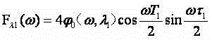
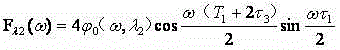
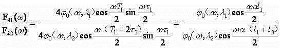
通过比较两者频谱上的幅度,消除了扰动信号幅度、频率成分变化对定位的影响。每个频率点都可以求得 
![]()
![]()
但在先技术二中,由于需要使用了相位生成载波调制技术,信号的解调变得相对复杂,特别是通常扰动引起的干涉信号带宽很宽,要精确地还原干涉相位,不仅要求带通滤波器的带宽很宽,且对平坦度和相移特性都有很高的要求,信号处理的难度和复杂程度较大。 However, in the second prior art, the demodulation of the signal becomes relatively complicated due to the need to use the phase generation carrier modulation technology, especially the interference signal caused by the disturbance usually has a wide bandwidth. To accurately restore the interference phase, not only the bandpass filter is required The bandwidth of the filter is very wide, and it has high requirements on flatness and phase shift characteristics, and the difficulty and complexity of signal processing are relatively large. the
发明内容 Contents of the invention
本发明的目的在于提出一种环境适用性强、结构简单的可用于长距离分布式监测的基于波分复用的分布式光纤定位干涉结构。 The purpose of the present invention is to propose a distributed optical fiber positioning interference structure based on wavelength division multiplexing that has strong environmental applicability and simple structure and can be used for long-distance distributed monitoring. the
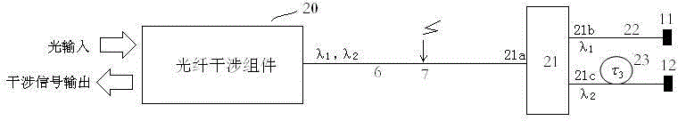
本发明提出的基于波分复用的分布式光纤定位干涉结构,使用波分复用技术,使得同一扰动,获得两种不同的干涉信号,可以利用比较两路相位信号的频谱特性的方法,确定扰动发生的位置。具体如图3所示。包括:光纤干涉组件20、感应光纤6、第一波分复用器21、第一光纤22、第二光纤23、第一反馈装置11、第二反馈装置12;两个不同波长的光λ1、λ2从同一根感应光纤6中注入,这两个注入光沿这根被复用的感应光纤6传输到光纤的端口,被第一波分复用器件21分开,分别沿各自的独立路径第一光纤22、第二光纤23到达各自的反射终端——第一反馈装置11、第二反馈装置12;这两个独立光纤路径第一光纤22、第二光纤23之间长度差为l 3 ,产生的时延为τ 3 。
The distributed optical fiber positioning interference structure based on wavelength division multiplexing proposed by the present invention uses wavelength division multiplexing technology, so that the same disturbance can obtain two different interference signals, and the method of comparing the spectral characteristics of the two phase signals can be used to determine The location where the disturbance occurs. Specifically shown in Figure 3. Including: optical fiber interference assembly 20, sensing
图3中,光纤干涉组件20和感应光纤6、第一波分复用器21、第一光纤22、第一反馈装置11共同形成光波λ1的干涉光路;光纤干涉组件20和感应光纤6、第一波分复用器21、第二光纤23、第二反馈装置12共同形成光波λ2的干涉光路。光从光纤干涉组件20输入,干涉信号亦从光纤干涉组件20输出。
Among Fig. 3, optical fiber interference assembly 20 and induction
光波λ1的干涉信号中携带有扰动点7距离反馈装置11长度信息,光波λ2的干涉信号中携带有扰动点7距离反馈装置12长度信息,这两个长度差(即为第一光纤22和第二光纤23的长度差)的存在,使得扰动点7的位置可以通过比较两个光波干涉获得的相位信号的频谱特性,获得准确的振动位置信息。
The interference signal of light wave λ 1 carries information about the length of the disturbance point 7 from the
图4是实现这一干涉结构的一种具体方式。 Figure 4 is a specific way to realize this interference structure. the
光纤干涉组件20由第一光纤分路器24、第二光纤分路器25、第二波分复用器26、第三波分复用器27、光纤延迟线5、第三光纤分路器28构成。其中,第一光纤分路器24是一N*M光纤分路器(N、M为整数),24a1、24a2、…24aN是第一光纤分路器24的N个同向端口,24b1、24b2属另一组同向端口。第二光纤分路器25是一P*Q光纤分路器(P、Q为整数),25a1、25a2、…25aP是第二光纤分路器25的P个同向端口,25b1、25b2属另一组同向端口。第二波分复用器26为一波分复用器,26b、26c是其独立波长端口,26a是复用波长端口。第三波分复用器27是另一波分复用器,27b、27c是其独立波长端口,27a是复用波长端口。第三光纤分路器28是一工作波长包括λ1、λ2的光纤分路器,28b1、28b2是其同向端口,28a是另一方向端口。波长λ1的第一光从光纤分路器24的24a1 输入,光从端口24b1、24b2输出;波长λ2的光从第二光纤分路器25的25a1 输入,光从端口25b1、25b2输出。从端口24b1、25b1输出的波长分别为λ1、λ2的光从第二经波分复用器26的端口26b、26c输入,两波长汇合的光从端口26a输出,复用端口26a与28b1间的路径;从端口24b2、25b2输出的波长分别为λ1、λ2的光从经第三波分复用器27的端口27b、27c输入,两波长汇合的光从端口27a输出,复用端口26a与28b2间的路径。从端口28b1、28b2输入的光,经28a输出,注入到感应光纤6中。在该干涉结构中,波长λ1的光产生的干涉信号从第一光纤分路器24的端口24a1、24a2、…24aN输出,波长λ2的光产生的干涉信号从第二光纤分路器25的端口25a1、25a2、…25aP输出。从λ1和λ2产生的干涉信号中分别解调出相应的相位信号,即可根据通过比较这两个相位信号的频谱特性确定扰动的位置。具体工作原理及解算过程如下。
The optical fiber interference assembly 20 is composed of a first
如图5所示在监控光纤的扰动点7处施加一个振动信号


在时刻t+τ(
(2) (2)
在一路传感光纤上,设扰动点7离反馈终装置R的距离为

上式中,
由频率为的扰动引起的干涉光的相位差为: from frequency to The phase difference of the interference light caused by the disturbance is:
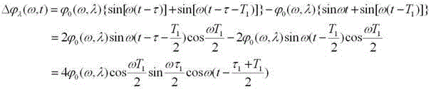
对于所有频率的扰动,总的相位差
设该光路为波长λ1的光的路径,即反馈装置R为反馈装置11,设扰动点7与反馈装置11的距离即为,干涉光组件20中光纤延迟线产生的时延为


对于波长为λ2的路径,反馈装置R为反馈装置12,因为光纤路径22和光纤路径23的延时差为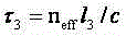


对于所有频率的扰动,光波λ1、λ2对应的总的相位差分别为: For disturbances of all frequencies, the total phase difference corresponding to light waves λ 1 and λ 2 are respectively:
这两个相位差分别由光纤分路器24、光纤分路器25输出的干涉光中解调出来。
The two phase differences are demodulated from the interference light output by the
在

由光弹效应可知,光纤受到外界应力作用时(假设不产生微弯),
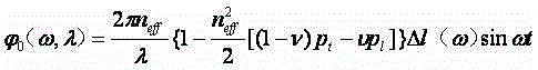
其中


则, but,
(11)式的左边通过实际测试获得,因此,对于每一个频率


图6是又一种干涉结构实现方式。 Fig. 6 is yet another implementation of the interference structure. the
光纤干涉组件20由第四光纤分路器29、第三光纤分路器28以及光纤延迟线5构成。第四光纤分路器29是一R*S光纤分路器(R、S为整数),29a1、29a2、…29aR是第四光纤分路器29的R个同向端口,29b1、29b2属另一组同向端口。该方式中,光纤干涉组件中20中所有的器件都被复用。端口29b1经光纤延迟线5与端口28b1相连,端口29b2与端口28b2相连,从端口28b1、28b2输入的光,经端口28a输出,注入到感应光纤6中。
The optical fiber interference assembly 20 is composed of a fourth optical fiber splitter 29 , a third
含有λ1和λ2两种波长成分的光从端口29a1输入,该注入光可以是由一个光源产生,也可以由波长分别为λ1和λ2的两个光源经波分复用器合波后生成。两种波长产生的干涉皆从端口29a1、29a2、…29aR输出。使用波分复用器即可把含有两个波长的干涉信号分离开,即分别获得λ1的干涉信号和λ2的干涉信号。从λ1和λ2产生的干涉信号中解调出相位信号,即可根据这两个相位信号确定扰动的位置。 The light containing two wavelength components of λ1 and λ2 is input from the port 29a1. The injected light can be generated by one light source, or can be combined by two light sources with wavelengths of λ1 and λ2 respectively through a wavelength division multiplexer generated after. The interference generated by the two wavelengths is output from the ports 29a1, 29a2, . . . 29aR. The interference signal containing two wavelengths can be separated by using a wavelength division multiplexer, that is, the interference signal of λ 1 and the interference signal of λ 2 are respectively obtained. The phase signal is demodulated from the interference signal generated by λ 1 and λ 2 , and the position of the disturbance can be determined according to the two phase signals.
本发明在干涉结构中使用波分复用技术,使得同一扰动,获得两种不同的干涉信号,可以利用比较两路相位信号的频谱特性的方法获得扰动的位置。这种形式,结构简单,后端信号处理无需特殊手段,这是该结构的一大优势。 The present invention uses wavelength division multiplexing technology in the interference structure, so that the same disturbance can obtain two different interference signals, and the position of the disturbance can be obtained by comparing the spectral characteristics of the two phase signals. This form has a simple structure and no special means are required for back-end signal processing, which is a major advantage of this structure. the
该发明可通过比较两个干涉获得的相位信号的频谱特性,获得扰动位置信息。这种方法不仅可消除了扰动信号幅度、频率成分变化对定位的影响,还可利用多个频率点获得的位置值进行平均,消除信号处理中误差的影响,获得高的定位精度,因而该结构与方法具有潜在定位精确度高的优势。同时,因其扰动位置的获取不依赖于扰动源激发某个特殊频率点,适用性更强,应用前途更加广泛。 The invention can obtain disturbance position information by comparing the frequency spectrum characteristics of two phase signals obtained by interference. This method can not only eliminate the influence of disturbance signal amplitude and frequency component changes on positioning, but also use the position values obtained at multiple frequency points to average, eliminate the influence of errors in signal processing, and obtain high positioning accuracy. The method has the advantage of potentially high positioning accuracy. At the same time, because the acquisition of the disturbance position does not depend on the excitation of a special frequency point by the disturbance source, the applicability is stronger and the application prospect is wider. the
该发明用做感应、定位的光纤不用闭合,无需构成环路,便于沿监测对象长距离铺设,环境适用性强。 The optical fiber used for sensing and positioning in the invention does not need to be closed, does not need to form a loop, is convenient for long-distance laying along the monitoring object, and has strong environmental applicability. the
基于发明的分布式光纤管线监控系统可广泛应用于通信干线、电力传输线、天然气管道、石油管道、边境线的安全监测领域的长距离监测;也能应用于大型建筑物例如水坝、隧道、矿井等的安全监测。 The distributed optical fiber pipeline monitoring system based on the invention can be widely used in long-distance monitoring in the field of safety monitoring of communication trunk lines, power transmission lines, natural gas pipelines, oil pipelines, and border lines; it can also be applied to large buildings such as dams, tunnels, mines, etc. safety monitoring. the
附图说明 Description of drawings
图1为利用频率缺失点来进行定位监测的一种全光纤白光干涉系统结构。系统由宽带光源8、光纤分路器1、光纤延迟线5、光纤分路器2、单芯光纤6、反馈装置3、探测器9、10、信号处理单元16构成,该系统利用白光进行干涉。光路中存在一段单芯光纤6,利用反馈装置3的作用,使从光纤6传输的光经反馈装置3作用后重新进入光纤6传输,获得的干涉信号从1的端口1b、1c输出,进入探测器9、10。17是由分路器1、2和延迟线5构成的干涉单元。
Figure 1 shows the structure of an all-fiber white light interference system that utilizes missing frequency points for positioning monitoring. The system consists of
图2是一种基于相位生成载波复用技术的光纤定位监测系统结构。15为调制模块调制模块15,4是分路器,13、14为光纤,两段光纤的长度差为l产生的时延为τ2.,18.、19为相位调制器,11、12为反馈装置。 Figure 2 is a structure of an optical fiber positioning and monitoring system based on phase generation and carrier multiplexing technology. 15 is modulation module modulation module 15, and 4 is splitter, and 13,14 are optical fibers, and the time delay that the length difference of two sections of optical fibers is 1 generation is τ 2. , 18.,19 are phase modulators, and 11,12 are feedback device.
图3是本发明提出的基于波分复用的分布式光纤定位干涉结构。20是光纤干涉组件,6为感应光纤,21为第一波分复用器,22、23分别为第一、第二光纤,11、12分别为第一、第二反馈装置。光从光纤干涉组件20输入,干涉信号亦从光纤干涉组件20输出。 Fig. 3 is a distributed optical fiber positioning interference structure based on wavelength division multiplexing proposed by the present invention. 20 is an optical fiber interference component, 6 is an induction optical fiber, 21 is a first wavelength division multiplexer, 22 and 23 are respectively a first and a second optical fiber, 11 and 12 are respectively a first and a second feedback device. The light is input from the optical fiber interference component 20 , and the interference signal is also output from the optical fiber interference component 20 . the
图4是本发明的干涉结构的一种具体实现方式。24是一N*M光纤分路器(N、M为整数),24a1、24a2、…24aN是光纤分路器24的N个同向端口,24b1、24b2属另一组同向端口。25是一P*Q光纤分路器(P、Q为整数),25a1、25a2、…24aP是光纤分路器25的P个同向端口,25b1、25b2属另一组同向端口。26是一波分复用器,26b、26c是其独立波长端口,26a是复用波长端口。27是又一波分复用器,27b、27c是其独立波长端口,27a是复用波长端口。28是一工作波长包括λ1、λ2的光纤分路器,28b1、28b2是其同向端口,28a是另一方向端口。
Fig. 4 is a specific implementation of the interference structure of the present invention. 24 is an N*M fiber optic splitter (N, M are integers), 24a1, 24a2, ... 24aN are N co-directional ports of the
图5是在监控线路上存在有一个扰动点7的示意图。 Fig. 5 is a schematic diagram of a disturbance point 7 existing on the monitoring line. the
图6是本发明的干涉结构的又一种具体实现方式。29是一R*S光纤分路器(R、S为整数),29a1、29a2、…29aR是光纤分路器29的R个同向端口,29b1、29b2属另一组同向端口。 Fig. 6 is yet another specific implementation of the interference structure of the present invention. 29 is an R*S fiber optic splitter (R and S are integers), 29a1, 29a2, ... 29aR are R co-directional ports of the fiber optic splitter 29, and 29b1 and 29b2 belong to another group of co-directional ports. the
具体实施方式 Detailed ways
下面通过实施例进一步描述本发明。采用图4所示的干涉结构。光源为电子集团总公司44研究所生产的中心波长分别为1300nm(λ1)和和1550nm(λ2)的超辐射发光管(SLD)。光纤耦合器、波分复用器为武汉邮电研究院生产。光纤分路器24采用工作波长1300nm的3*3均分耦合器,光纤分路器25采用工作波长1550nm的3*3均分耦合器,光纤分路器28采用2*2均分的双窗口光纤耦合器,波分复用器21、26、27为1300nm、1550nm的波分复用器。1300nm的光从端口24a1输入,形成的干涉信号从端口24a2和24a3取出;1550nm的光从端口25a1输入,形成的干涉信号从端口25a2和25a3取出。采用44所生产的型号为GT322C500的InGaAs光电探测器将光干涉信号转为电信号。通过National Instruments公司数据采集卡PCI-6122将电信号信号采集进计算机进行信号处理。监控线路铺设于需要监控管线的附近,光纤干涉模块需置于隔音设备中以屏蔽外界干扰。结果表明,能方便地获得准确的扰动位置。
The present invention is further described below by way of examples. Use the interference structure shown in Figure 4. The light sources are superluminescent diodes (SLD) with center wavelengths of 1300nm (λ 1 ) and 1550nm (λ 2 ) produced by the 44 Research Institute of Electronics Group Corporation. Fiber coupler and wavelength division multiplexer are produced by Wuhan Institute of Posts and Telecommunications.
Claims (1)
Priority Applications (1)
| Application Number | Priority Date | Filing Date | Title |
|---|---|---|---|
| CN2010105585066A CN102064884B (en) | 2010-11-25 | 2010-11-25 | Long-distance distributed optical fiber positioning interference structure based on wavelength division multiplexing (WDM) |
Applications Claiming Priority (1)
| Application Number | Priority Date | Filing Date | Title |
|---|---|---|---|
| CN2010105585066A CN102064884B (en) | 2010-11-25 | 2010-11-25 | Long-distance distributed optical fiber positioning interference structure based on wavelength division multiplexing (WDM) |
Publications (2)
| Publication Number | Publication Date |
|---|---|
| CN102064884A CN102064884A (en) | 2011-05-18 |
| CN102064884B true CN102064884B (en) | 2013-06-12 |
Family
ID=44000006
Family Applications (1)
| Application Number | Title | Priority Date | Filing Date |
|---|---|---|---|
| CN2010105585066A Active CN102064884B (en) | 2010-11-25 | 2010-11-25 | Long-distance distributed optical fiber positioning interference structure based on wavelength division multiplexing (WDM) |
Country Status (1)
| Country | Link |
|---|---|
| CN (1) | CN102064884B (en) |
Families Citing this family (15)
| Publication number | Priority date | Publication date | Assignee | Title |
|---|---|---|---|---|
| CN102496231B (en) * | 2011-11-25 | 2014-01-15 | 北京航天易联科技发展有限公司 | Long-distance Trunk Safety Optical Fiber Wavelength Division Multiplexing Early Warning System |
| CN102635399A (en) * | 2012-04-25 | 2012-08-15 | 复旦大学 | Mine emergency rescue communication method and system based on optical fiber sensing |
| CN103499356B (en) * | 2013-10-12 | 2017-07-07 | 复旦大学 | The method and structure of abatement fiber optic interferometric system transmission path signal interference |
| CN103487067B (en) * | 2013-10-12 | 2016-05-11 | 复旦大学 | Utilize wavelength-division multiplex technique to subdue the method and system of interference path scattering, reverberation interference |
| CN103560824A (en) * | 2013-10-30 | 2014-02-05 | 北京航天易联科技发展有限公司 | Optical cable fault nondestructive testing device and method based on optical fiber interference principle |
| CN103743421B (en) * | 2013-12-31 | 2016-05-18 | 上海华魏光纤传感技术有限公司 | Based on many method for sensing of single optical fibre |
| EP3105548A2 (en) | 2014-02-10 | 2016-12-21 | University of Central Florida Research Foundation, Inc. | Multicore optical fiber apparatus, methods, and applications |
| CN105488935B (en) * | 2015-12-25 | 2018-01-16 | 天津大学 | A kind of distributed optical fiber disturbance positioning system and its localization method based on asymmetric double Mach Zehnder interference |
| CN109150310A (en) * | 2017-06-28 | 2019-01-04 | 中国人民解放军61905部队 | Provisional communication method based on existing optical cable |
| CN110530498B (en) * | 2019-08-09 | 2021-08-17 | 国家电网有限公司 | Long-distance optical cable dynamic monitoring system |
| CN111157100B (en) * | 2020-01-02 | 2022-05-20 | 河海大学常州校区 | All-fiber sensing positioning system and positioning method based on feedback |
| CN111157102B (en) * | 2020-01-02 | 2022-03-08 | 河海大学常州校区 | Positioning method for eliminating frequency interference in distributed optical fiber sensing system |
| CN112399153A (en) * | 2020-11-30 | 2021-02-23 | 深圳市广为通信技术有限公司 | Optical fiber home-to-home transmission equipment received by dual-polarization satellite signal single satellite machine |
| CN113358985A (en) * | 2021-05-17 | 2021-09-07 | 广东电网有限责任公司 | Insulation fault positioning system |
| CN113390447B (en) * | 2021-06-17 | 2022-03-29 | 复旦大学 | Frequency response compensation method of optical fiber differential interference sensing system based on frequency response compensation |
Citations (3)
| Publication number | Priority date | Publication date | Assignee | Title |
|---|---|---|---|---|
| US5555118A (en) * | 1993-06-04 | 1996-09-10 | Ciena Corporation | Method for removing and inserting optical carriers in a WDM optical communication system |
| CN101080884A (en) * | 2004-12-17 | 2007-11-28 | 英国电讯有限公司 | network assessment |
| CN101277151A (en) * | 2008-05-16 | 2008-10-01 | 北京邮电大学 | A Fiber Optic Sensing System Architecture Based on Wavelength Division Multiplexing |
-
2010
- 2010-11-25 CN CN2010105585066A patent/CN102064884B/en active Active
Patent Citations (3)
| Publication number | Priority date | Publication date | Assignee | Title |
|---|---|---|---|---|
| US5555118A (en) * | 1993-06-04 | 1996-09-10 | Ciena Corporation | Method for removing and inserting optical carriers in a WDM optical communication system |
| CN101080884A (en) * | 2004-12-17 | 2007-11-28 | 英国电讯有限公司 | network assessment |
| CN101277151A (en) * | 2008-05-16 | 2008-10-01 | 北京邮电大学 | A Fiber Optic Sensing System Architecture Based on Wavelength Division Multiplexing |
Also Published As
| Publication number | Publication date |
|---|---|
| CN102064884A (en) | 2011-05-18 |
Similar Documents
| Publication | Publication Date | Title |
|---|---|---|
| CN102064884B (en) | Long-distance distributed optical fiber positioning interference structure based on wavelength division multiplexing (WDM) | |
| CN101242224A (en) | Optical fiber pipeline monitoring system | |
| CN102506913B (en) | Interference type optical fiber distribution disturbance sensor and disturbance location method thereof | |
| CN104819770B (en) | Phase optical time domain reflecting device and method with phase demodulating is detected based on heterodyne | |
| CN102997946B (en) | Fiber-distributed disturbance sensor and disturbance positioning method thereof | |
| CN101922946A (en) | An all-optical fiber positioning monitoring system | |
| CN102538845B (en) | Multi-point disturbance location method | |
| CN104848980B (en) | Bridge cable Suo Li online test methods and system based on Fibre Optical Sensor | |
| CN102538846A (en) | Phase-sensitive optical time domain reflectometer type optical fiber distributed disturbing sensor of double-arm pulse optical interference | |
| CN102564476B (en) | Multipoint disturbance positioning method | |
| CN109238319A (en) | A kind of optical fiber sound temperature and pressure compound sensor | |
| CN108760021A (en) | Fabry-perot optical fiber acoustic vibration sensing device based on birefringece crystal and demodulation method | |
| CN102003971B (en) | Method for eliminating backscattering light influence in optical fiber sensor | |
| Song et al. | Fiber optic sensor based on linear Sagnac interferometer for branch localization | |
| CN104077267A (en) | Location method for double Fourier transform and disturbance | |
| US10024697B2 (en) | Method and system using wavelength division multiplexing for eliminating and reducing light diffusion and light reflection interference in interference path | |
| CN102087356B (en) | Method for processing two superposed composite signals with fixed time delay difference | |
| CN112033567A (en) | An Optical Fiber Sensing System for Separate Measurement of OPGW Overhead Ground Wire Temperature and Vibration | |
| CN208672199U (en) | A Device for Distributed Strain Sensing Using Optical Frequency Domain Reflectance | |
| CN103674080A (en) | Optical fiber interference method and system aimed at weak signal detection | |
| CN102033226B (en) | Method for improving monitoring distance of single-core feedback optical fiber sensing technology and optical fiber interference structure | |
| CN116592922B (en) | Branch distributed positioning system based on single-core feedback interferometer | |
| CN203704952U (en) | Optical fiber interference system for weak signal detection | |
| CN102496231B (en) | Long-distance Trunk Safety Optical Fiber Wavelength Division Multiplexing Early Warning System | |
| CN107314823A (en) | The Method for Phase Difference Measurement and device of interferometric optical fiber sensor |
Legal Events
| Date | Code | Title | Description |
|---|---|---|---|
| C06 | Publication | ||
| PB01 | Publication | ||
| C10 | Entry into substantive examination | ||
| SE01 | Entry into force of request for substantive examination | ||
| C14 | Grant of patent or utility model | ||
| GR01 | Patent grant | ||
| EE01 | Entry into force of recordation of patent licensing contract |
Application publication date: 20110518 Assignee: Dongguan advanced optical fiber Application Technology Research Institute Co Ltd Assignor: Fudan University Contract record no.: 2018310000016 Denomination of invention: Long-distance distributed optical fiber positioning interference structure based on wavelength division multiplexing (WDM) Granted publication date: 20130612 License type: Exclusive License Record date: 20180529 |
|
| EE01 | Entry into force of recordation of patent licensing contract |