CN103365653A - Information providing device, image forming device, and transmission system - Google Patents
Information providing device, image forming device, and transmission system Download PDFInfo
- Publication number
- CN103365653A CN103365653A CN2013101802289A CN201310180228A CN103365653A CN 103365653 A CN103365653 A CN 103365653A CN 2013101802289 A CN2013101802289 A CN 2013101802289A CN 201310180228 A CN201310180228 A CN 201310180228A CN 103365653 A CN103365653 A CN 103365653A
- Authority
- CN
- China
- Prior art keywords
- data
- unit
- information
- communication
- information provider
- Prior art date
- Legal status (The legal status is an assumption and is not a legal conclusion. Google has not performed a legal analysis and makes no representation as to the accuracy of the status listed.)
- Pending
Links
- 230000005540 biological transmission Effects 0.000 title claims abstract description 348
- 238000004891 communication Methods 0.000 claims abstract description 281
- 238000003860 storage Methods 0.000 claims abstract description 132
- 238000012545 processing Methods 0.000 claims description 82
- 238000000034 method Methods 0.000 claims description 59
- 230000015572 biosynthetic process Effects 0.000 claims description 17
- 230000006870 function Effects 0.000 description 69
- 238000010586 diagram Methods 0.000 description 63
- 238000007726 management method Methods 0.000 description 50
- 230000008569 process Effects 0.000 description 41
- 238000009826 distribution Methods 0.000 description 26
- 238000013481 data capture Methods 0.000 description 23
- 238000013500 data storage Methods 0.000 description 23
- 238000013475 authorization Methods 0.000 description 15
- 239000000463 material Substances 0.000 description 14
- 238000012546 transfer Methods 0.000 description 14
- 238000009434 installation Methods 0.000 description 12
- 238000007639 printing Methods 0.000 description 12
- 238000003825 pressing Methods 0.000 description 10
- 230000009471 action Effects 0.000 description 6
- 230000008859 change Effects 0.000 description 5
- 230000002093 peripheral effect Effects 0.000 description 5
- 230000004044 response Effects 0.000 description 5
- 241001269238 Data Species 0.000 description 4
- 238000009825 accumulation Methods 0.000 description 4
- 238000013523 data management Methods 0.000 description 4
- 238000005516 engineering process Methods 0.000 description 4
- 230000014759 maintenance of location Effects 0.000 description 4
- 230000009467 reduction Effects 0.000 description 4
- 239000012634 fragment Substances 0.000 description 3
- 239000004973 liquid crystal related substance Substances 0.000 description 3
- 238000000926 separation method Methods 0.000 description 3
- 238000012795 verification Methods 0.000 description 3
- 239000004606 Fillers/Extenders Substances 0.000 description 2
- 238000006243 chemical reaction Methods 0.000 description 2
- 230000010354 integration Effects 0.000 description 2
- 230000005039 memory span Effects 0.000 description 2
- 230000035807 sensation Effects 0.000 description 2
- 230000005236 sound signal Effects 0.000 description 2
- 230000000007 visual effect Effects 0.000 description 2
- 230000001133 acceleration Effects 0.000 description 1
- 238000004458 analytical method Methods 0.000 description 1
- 230000001174 ascending effect Effects 0.000 description 1
- 230000004888 barrier function Effects 0.000 description 1
- 230000008901 benefit Effects 0.000 description 1
- 230000000295 complement effect Effects 0.000 description 1
- 230000003750 conditioning effect Effects 0.000 description 1
- 238000012790 confirmation Methods 0.000 description 1
- 238000012937 correction Methods 0.000 description 1
- 230000003111 delayed effect Effects 0.000 description 1
- 238000009792 diffusion process Methods 0.000 description 1
- 239000012769 display material Substances 0.000 description 1
- 230000000694 effects Effects 0.000 description 1
- 238000003384 imaging method Methods 0.000 description 1
- 230000010365 information processing Effects 0.000 description 1
- 230000002452 interceptive effect Effects 0.000 description 1
- 238000012423 maintenance Methods 0.000 description 1
- 229910044991 metal oxide Inorganic materials 0.000 description 1
- 150000004706 metal oxides Chemical class 0.000 description 1
- 238000010295 mobile communication Methods 0.000 description 1
- 238000006386 neutralization reaction Methods 0.000 description 1
- 238000010606 normalization Methods 0.000 description 1
- 239000004065 semiconductor Substances 0.000 description 1
- 238000012384 transportation and delivery Methods 0.000 description 1
Images


Classifications
-
- H—ELECTRICITY
- H04—ELECTRIC COMMUNICATION TECHNIQUE
- H04N—PICTORIAL COMMUNICATION, e.g. TELEVISION
- H04N1/00—Scanning, transmission or reproduction of documents or the like, e.g. facsimile transmission; Details thereof
- H04N1/00127—Connection or combination of a still picture apparatus with another apparatus, e.g. for storage, processing or transmission of still picture signals or of information associated with a still picture
- H04N1/00281—Connection or combination of a still picture apparatus with another apparatus, e.g. for storage, processing or transmission of still picture signals or of information associated with a still picture with a telecommunication apparatus, e.g. a switched network of teleprinters for the distribution of text-based information, a selective call terminal
- H04N1/00283—Connection or combination of a still picture apparatus with another apparatus, e.g. for storage, processing or transmission of still picture signals or of information associated with a still picture with a telecommunication apparatus, e.g. a switched network of teleprinters for the distribution of text-based information, a selective call terminal with a television apparatus
- H04N1/00299—Connection or combination of a still picture apparatus with another apparatus, e.g. for storage, processing or transmission of still picture signals or of information associated with a still picture with a telecommunication apparatus, e.g. a switched network of teleprinters for the distribution of text-based information, a selective call terminal with a television apparatus with a television transmission apparatus, e.g. a videophone, a teletext system or a digital television system
-
- H—ELECTRICITY
- H04—ELECTRIC COMMUNICATION TECHNIQUE
- H04N—PICTORIAL COMMUNICATION, e.g. TELEVISION
- H04N1/00—Scanning, transmission or reproduction of documents or the like, e.g. facsimile transmission; Details thereof
- H04N1/00127—Connection or combination of a still picture apparatus with another apparatus, e.g. for storage, processing or transmission of still picture signals or of information associated with a still picture
- H04N1/00204—Connection or combination of a still picture apparatus with another apparatus, e.g. for storage, processing or transmission of still picture signals or of information associated with a still picture with a digital computer or a digital computer system, e.g. an internet server
- H04N1/00209—Transmitting or receiving image data, e.g. facsimile data, via a computer, e.g. using e-mail, a computer network, the internet, I-fax
- H04N1/00214—Transmitting or receiving image data, e.g. facsimile data, via a computer, e.g. using e-mail, a computer network, the internet, I-fax details of transmission
- H04N1/00217—Transmitting or receiving image data, e.g. facsimile data, via a computer, e.g. using e-mail, a computer network, the internet, I-fax details of transmission only involving computer data transmission protocols, e.g. SMTP, WAP or HTTP
-
- H—ELECTRICITY
- H04—ELECTRIC COMMUNICATION TECHNIQUE
- H04N—PICTORIAL COMMUNICATION, e.g. TELEVISION
- H04N1/00—Scanning, transmission or reproduction of documents or the like, e.g. facsimile transmission; Details thereof
- H04N1/00127—Connection or combination of a still picture apparatus with another apparatus, e.g. for storage, processing or transmission of still picture signals or of information associated with a still picture
- H04N1/00204—Connection or combination of a still picture apparatus with another apparatus, e.g. for storage, processing or transmission of still picture signals or of information associated with a still picture with a digital computer or a digital computer system, e.g. an internet server
- H04N1/00209—Transmitting or receiving image data, e.g. facsimile data, via a computer, e.g. using e-mail, a computer network, the internet, I-fax
- H04N1/00222—Transmitting or receiving image data, e.g. facsimile data, via a computer, e.g. using e-mail, a computer network, the internet, I-fax details of image data generation or reproduction, e.g. scan-to-email or network printing
- H04N1/00225—Transmitting or receiving image data, e.g. facsimile data, via a computer, e.g. using e-mail, a computer network, the internet, I-fax details of image data generation or reproduction, e.g. scan-to-email or network printing details of image data generation, e.g. scan-to-email or network scanners
-
- H—ELECTRICITY
- H04—ELECTRIC COMMUNICATION TECHNIQUE
- H04N—PICTORIAL COMMUNICATION, e.g. TELEVISION
- H04N1/00—Scanning, transmission or reproduction of documents or the like, e.g. facsimile transmission; Details thereof
- H04N1/00127—Connection or combination of a still picture apparatus with another apparatus, e.g. for storage, processing or transmission of still picture signals or of information associated with a still picture
- H04N1/00204—Connection or combination of a still picture apparatus with another apparatus, e.g. for storage, processing or transmission of still picture signals or of information associated with a still picture with a digital computer or a digital computer system, e.g. an internet server
- H04N1/00244—Connection or combination of a still picture apparatus with another apparatus, e.g. for storage, processing or transmission of still picture signals or of information associated with a still picture with a digital computer or a digital computer system, e.g. an internet server with a server, e.g. an internet server
-
- H—ELECTRICITY
- H04—ELECTRIC COMMUNICATION TECHNIQUE
- H04N—PICTORIAL COMMUNICATION, e.g. TELEVISION
- H04N1/00—Scanning, transmission or reproduction of documents or the like, e.g. facsimile transmission; Details thereof
- H04N1/00127—Connection or combination of a still picture apparatus with another apparatus, e.g. for storage, processing or transmission of still picture signals or of information associated with a still picture
- H04N1/00281—Connection or combination of a still picture apparatus with another apparatus, e.g. for storage, processing or transmission of still picture signals or of information associated with a still picture with a telecommunication apparatus, e.g. a switched network of teleprinters for the distribution of text-based information, a selective call terminal
- H04N1/00307—Connection or combination of a still picture apparatus with another apparatus, e.g. for storage, processing or transmission of still picture signals or of information associated with a still picture with a telecommunication apparatus, e.g. a switched network of teleprinters for the distribution of text-based information, a selective call terminal with a mobile telephone apparatus
-
- H—ELECTRICITY
- H04—ELECTRIC COMMUNICATION TECHNIQUE
- H04N—PICTORIAL COMMUNICATION, e.g. TELEVISION
- H04N1/00—Scanning, transmission or reproduction of documents or the like, e.g. facsimile transmission; Details thereof
- H04N1/00127—Connection or combination of a still picture apparatus with another apparatus, e.g. for storage, processing or transmission of still picture signals or of information associated with a still picture
- H04N1/00347—Connection or combination of a still picture apparatus with another apparatus, e.g. for storage, processing or transmission of still picture signals or of information associated with a still picture with another still picture apparatus, e.g. hybrid still picture apparatus
-
- H—ELECTRICITY
- H04—ELECTRIC COMMUNICATION TECHNIQUE
- H04N—PICTORIAL COMMUNICATION, e.g. TELEVISION
- H04N1/00—Scanning, transmission or reproduction of documents or the like, e.g. facsimile transmission; Details thereof
- H04N1/0035—User-machine interface; Control console
- H04N1/00405—Output means
- H04N1/00408—Display of information to the user, e.g. menus
- H04N1/00413—Display of information to the user, e.g. menus using menus, i.e. presenting the user with a plurality of selectable options
-
- H—ELECTRICITY
- H04—ELECTRIC COMMUNICATION TECHNIQUE
- H04N—PICTORIAL COMMUNICATION, e.g. TELEVISION
- H04N1/00—Scanning, transmission or reproduction of documents or the like, e.g. facsimile transmission; Details thereof
- H04N1/0035—User-machine interface; Control console
- H04N1/00405—Output means
- H04N1/00408—Display of information to the user, e.g. menus
- H04N1/0044—Display of information to the user, e.g. menus for image preview or review, e.g. to help the user position a sheet
-
- H—ELECTRICITY
- H04—ELECTRIC COMMUNICATION TECHNIQUE
- H04N—PICTORIAL COMMUNICATION, e.g. TELEVISION
- H04N1/00—Scanning, transmission or reproduction of documents or the like, e.g. facsimile transmission; Details thereof
- H04N1/00962—Input arrangements for operating instructions or parameters, e.g. updating internal software
- H04N1/00973—Input arrangements for operating instructions or parameters, e.g. updating internal software from a remote device, e.g. receiving via the internet instructions input to a computer terminal
-
- H—ELECTRICITY
- H04—ELECTRIC COMMUNICATION TECHNIQUE
- H04N—PICTORIAL COMMUNICATION, e.g. TELEVISION
- H04N1/00—Scanning, transmission or reproduction of documents or the like, e.g. facsimile transmission; Details thereof
- H04N1/21—Intermediate information storage
-
- H—ELECTRICITY
- H04—ELECTRIC COMMUNICATION TECHNIQUE
- H04N—PICTORIAL COMMUNICATION, e.g. TELEVISION
- H04N1/00—Scanning, transmission or reproduction of documents or the like, e.g. facsimile transmission; Details thereof
- H04N1/32—Circuits or arrangements for control or supervision between transmitter and receiver or between image input and image output device, e.g. between a still-image camera and its memory or between a still-image camera and a printer device
- H04N1/32358—Circuits or arrangements for control or supervision between transmitter and receiver or between image input and image output device, e.g. between a still-image camera and its memory or between a still-image camera and a printer device using picture signal storage, e.g. at transmitter
- H04N1/324—Circuits or arrangements for control or supervision between transmitter and receiver or between image input and image output device, e.g. between a still-image camera and its memory or between a still-image camera and a printer device using picture signal storage, e.g. at transmitter intermediate the transmitter and receiver terminals, e.g. at an exchange
- H04N1/32432—Circuits or arrangements for control or supervision between transmitter and receiver or between image input and image output device, e.g. between a still-image camera and its memory or between a still-image camera and a printer device using picture signal storage, e.g. at transmitter intermediate the transmitter and receiver terminals, e.g. at an exchange in a particular memory file for retrieval by the user, e.g. in a facsimile mailbox
-
- H—ELECTRICITY
- H04—ELECTRIC COMMUNICATION TECHNIQUE
- H04N—PICTORIAL COMMUNICATION, e.g. TELEVISION
- H04N1/00—Scanning, transmission or reproduction of documents or the like, e.g. facsimile transmission; Details thereof
- H04N1/32—Circuits or arrangements for control or supervision between transmitter and receiver or between image input and image output device, e.g. between a still-image camera and its memory or between a still-image camera and a printer device
- H04N1/327—Initiating, continuing or ending a single-mode communication; Handshaking therefor
- H04N1/32765—Initiating a communication
- H04N1/32771—Initiating a communication in response to a request, e.g. for a particular document
- H04N1/32776—Initiating a communication in response to a request, e.g. for a particular document using an interactive, user-operated device, e.g. a computer terminal, mobile telephone
-
- H—ELECTRICITY
- H04—ELECTRIC COMMUNICATION TECHNIQUE
- H04N—PICTORIAL COMMUNICATION, e.g. TELEVISION
- H04N7/00—Television systems
- H04N7/14—Systems for two-way working
- H04N7/15—Conference systems
-
- H—ELECTRICITY
- H04—ELECTRIC COMMUNICATION TECHNIQUE
- H04N—PICTORIAL COMMUNICATION, e.g. TELEVISION
- H04N1/00—Scanning, transmission or reproduction of documents or the like, e.g. facsimile transmission; Details thereof
- H04N1/0035—User-machine interface; Control console
- H04N1/00405—Output means
- H04N1/00408—Display of information to the user, e.g. menus
- H04N1/00411—Display of information to the user, e.g. menus the display also being used for user input, e.g. touch screen
-
- H—ELECTRICITY
- H04—ELECTRIC COMMUNICATION TECHNIQUE
- H04N—PICTORIAL COMMUNICATION, e.g. TELEVISION
- H04N2201/00—Indexing scheme relating to scanning, transmission or reproduction of documents or the like, and to details thereof
- H04N2201/0008—Connection or combination of a still picture apparatus with another apparatus
- H04N2201/0034—Details of the connection, e.g. connector, interface
- H04N2201/0036—Detecting or checking connection
-
- H—ELECTRICITY
- H04—ELECTRIC COMMUNICATION TECHNIQUE
- H04N—PICTORIAL COMMUNICATION, e.g. TELEVISION
- H04N2201/00—Indexing scheme relating to scanning, transmission or reproduction of documents or the like, and to details thereof
- H04N2201/0008—Connection or combination of a still picture apparatus with another apparatus
- H04N2201/0034—Details of the connection, e.g. connector, interface
- H04N2201/0037—Topological details of the connection
- H04N2201/0039—Connection via a network
-
- H—ELECTRICITY
- H04—ELECTRIC COMMUNICATION TECHNIQUE
- H04N—PICTORIAL COMMUNICATION, e.g. TELEVISION
- H04N2201/00—Indexing scheme relating to scanning, transmission or reproduction of documents or the like, and to details thereof
- H04N2201/0008—Connection or combination of a still picture apparatus with another apparatus
- H04N2201/0034—Details of the connection, e.g. connector, interface
- H04N2201/0037—Topological details of the connection
- H04N2201/0041—Point to point
-
- H—ELECTRICITY
- H04—ELECTRIC COMMUNICATION TECHNIQUE
- H04N—PICTORIAL COMMUNICATION, e.g. TELEVISION
- H04N2201/00—Indexing scheme relating to scanning, transmission or reproduction of documents or the like, and to details thereof
- H04N2201/0008—Connection or combination of a still picture apparatus with another apparatus
- H04N2201/0034—Details of the connection, e.g. connector, interface
- H04N2201/0044—Connecting to a plurality of different apparatus; Using a plurality of different connectors
-
- H—ELECTRICITY
- H04—ELECTRIC COMMUNICATION TECHNIQUE
- H04N—PICTORIAL COMMUNICATION, e.g. TELEVISION
- H04N2201/00—Indexing scheme relating to scanning, transmission or reproduction of documents or the like, and to details thereof
- H04N2201/0008—Connection or combination of a still picture apparatus with another apparatus
- H04N2201/0034—Details of the connection, e.g. connector, interface
- H04N2201/0048—Type of connection
- H04N2201/0055—By radio
-
- H—ELECTRICITY
- H04—ELECTRIC COMMUNICATION TECHNIQUE
- H04N—PICTORIAL COMMUNICATION, e.g. TELEVISION
- H04N2201/00—Indexing scheme relating to scanning, transmission or reproduction of documents or the like, and to details thereof
- H04N2201/0008—Connection or combination of a still picture apparatus with another apparatus
- H04N2201/0034—Details of the connection, e.g. connector, interface
- H04N2201/0048—Type of connection
- H04N2201/006—Using near field communication, e.g. an inductive loop
-
- H—ELECTRICITY
- H04—ELECTRIC COMMUNICATION TECHNIQUE
- H04N—PICTORIAL COMMUNICATION, e.g. TELEVISION
- H04N2201/00—Indexing scheme relating to scanning, transmission or reproduction of documents or the like, and to details thereof
- H04N2201/0008—Connection or combination of a still picture apparatus with another apparatus
- H04N2201/0074—Arrangements for the control of a still picture apparatus by the connected apparatus
- H04N2201/0075—Arrangements for the control of a still picture apparatus by the connected apparatus by a user operated remote control device, e.g. receiving instructions from a user via a computer terminal or mobile telephone handset
-
- H—ELECTRICITY
- H04—ELECTRIC COMMUNICATION TECHNIQUE
- H04N—PICTORIAL COMMUNICATION, e.g. TELEVISION
- H04N2201/00—Indexing scheme relating to scanning, transmission or reproduction of documents or the like, and to details thereof
- H04N2201/0077—Types of the still picture apparatus
- H04N2201/0094—Multifunctional device, i.e. a device capable of all of reading, reproducing, copying, facsimile transception, file transception
-
- H—ELECTRICITY
- H04—ELECTRIC COMMUNICATION TECHNIQUE
- H04N—PICTORIAL COMMUNICATION, e.g. TELEVISION
- H04N2201/00—Indexing scheme relating to scanning, transmission or reproduction of documents or the like, and to details thereof
- H04N2201/0096—Portable devices
Landscapes
- Engineering & Computer Science (AREA)
- Multimedia (AREA)
- Signal Processing (AREA)
- General Engineering & Computer Science (AREA)
- Human Computer Interaction (AREA)
- Computing Systems (AREA)
- Computer Networks & Wireless Communication (AREA)
- Facsimiles In General (AREA)
- Two-Way Televisions, Distribution Of Moving Picture Or The Like (AREA)
- Information Transfer Between Computers (AREA)
Abstract
An information providing device is capable of communicating with an image forming device, a data managing device, and a transmission terminal. The information providing device includes a storage unit; a communication unit that transmits a scanning instruction to instruct the image forming device to perform image scanning, and receives, from the image forming device, storage location information indicating the data managing device that stores data obtained by image scanning by the image forming device and indicating a storage location in the data managing device; and a storage location managing unit that generates, in the storage unit, management information in which identification information of the image data is associated with the storage location information. The communication unit receives the data saved in the storage location indicated by the storage location information from the data managing device and transmits the received data to the transmission terminal.
Description
The cross reference of related application
Japanese patent application 2012-064516 number of requiring to submit in Japan on March 21st, 2012 of the application is right of priority, and by reference its full content merged.
Technical field
The present invention relates to information provider unit, image processing system and transmission system.
Background technology
The communication system that is used for carrying out via the communication network such as the Internet meeting etc. is being commonly used in recent years.In such communication system, each communication terminal with camera, microphone, loudspeaker etc. is used.When communication terminal begins to communicate with another communication terminal, communication terminal be configured to sending/receiving by they separately the camera of communication terminal and microphone obtain catch view data (view data) and voice data, in order to allow to carry out video conference.
In above-mentioned communication system, the screen that presents material etc. that is presented on the communication terminal also is sent out/receives as the demonstration data except above-mentioned data, in order to improve and the communicating with each other of other participants.Then, received the communication terminal that shows data and demonstrated the demonstration data in display device, this display device allows to present material etc. and shares between communicator.
For example, Japanese patent application publication number 2009-135865 discloses a kind of signal conditioning package, its for set up easily radio communication and process easily the sending/receiving data purpose and by using the configuration information that is received by the first communication unit to set up the second communication unit in the second communication unit and sending the data of file reading to mobile communication terminal via the second communication unit.
Require a large amount of operation stepss, and therefore the shared file data that reads from scanner is trouble.For example, suppose following situation: the user of teleconference takes back the paper material of outside meeting distribution his/her office and share these materials in teleconference.In this case, this user need to use network scanner to read the paper material that these take back, and via corporate lan storage of electronic on portable terminal device.
Yet for the data transmission from the scanner to the portable terminal device in the prior art, the user at first needs to carry out the operation of named place of destination on scanner and then carries out read operation.The user further need to carry out the operation of seeking the position of storing received data in portable terminal device, and then begins to allow the application software that data are shown.As mentioned above, there is the shortcoming require a large amount of operation stepss and therefore to share the file data trouble that reads from scanner.
Thereby existence can be shared the needs of information provider unit, image processing system and the transmission system of the view data that is formed by image processing system easily.
Summary of the invention
According to an embodiment, provide a kind of information provider unit that can communicate with image processing system, data administrator and transmission terminal.Described information provider unit comprises: storage unit; Communication unit, it sends the formation instruction and forms with instruction image processing system carries out image, and receive stored position information from image processing system, described stored position information designation data management devices storage is carried out image by image processing system and is formed and the data that obtain and the memory location of indicating at data administrator; And the memory location administrative unit, it generates management information in storage unit, and wherein the identifying information of view data is associated with stored position information.Described communication unit receives the Data Concurrent that is stored in the memory location of being indicated by stored position information from data administrator and send described receive data to transmission terminal.
According to another embodiment, provide the information provider unit that can communicate with image processing system, data administrator and transmission terminal.Described information provider unit comprises: storage unit; Communication unit, it receive to be used for carries out File Control Procedure to the document control of the data that generated by image processing system from image processing system; And the program management unit, it is the storage file control program in storage unit.Described File Control Procedure is so that computing machine is carried out following operation: send the formation instruction and form with instruction image processing system carries out image; Form device from figure and receive stored position information, described stored position information designation data management devices storage is undertaken that image forms and the data that obtain by image processing system, and indicates from the memory location in the data administrator of image processing system; Generate management information in storage unit, wherein the identifying information of data is associated with stored position information; Receive the data that are stored in by the memory location of described stored position information indication from data administrator; And transmitting and receiving data is to transmission terminal.
According to another embodiment, provide the image processing system that to communicate by letter with data administrator with information provider unit.Described image processing system comprises: scanning element, and it reads paper document; Communication unit receives the formation instruction from information provider unit and forms with the instruction figure picture; Image formation unit, its image of carrying out the paper document that is read by described scanning element according to the formation instruction forms with image data generating; And the stored position information administrative unit, generate stored position information, the data administrator of described stored position information indication storage data and the memory location that in this data administrator, sets in advance.Described communication unit sends data to data administrator, and further sends stored position information to information provider unit.
According to another embodiment, transmission system is provided, it comprises image processing system, information provider unit, data administrator and transmission terminal.Described image processing system comprises: the first communication unit, and it provides the unit to receive the formation instruction from information and forms with the instruction figure picture; Image formation unit, it forms according to forming the instruction carries out image; With the stored position information administrative unit, it generates stored position information, the described data administrator of indication storage data and the memory location that sets in advance at described data administrator.Described the first communication unit sends data to data administrator, and further sends stored position information to information provider unit.Described information provider unit comprises: storage unit; The second communication unit, it sends the formation instruction and forms with instruction image processing system carries out image, and receiving stored position information from described image processing system, described stored position information designation data management devices storage is undertaken by image processing system that image forms and the data that obtain and indicate memory location in data administrator; And the memory location administrative unit, it generates management information in storage unit, and the identifying information of wherein said data is associated with described stored position information.Described second communication unit is received in the data of storing the memory location of being indicated by described stored position information from described data administrator, and sends described receive data to transmission terminal.Described transmission terminal is from the information provider unit receive data, and shared described receive data.
When considered in conjunction with the accompanying drawings, by reading the detailed description of following preferred embodiment of the present invention, above and other purpose of the present invention, feature, advantage and technology will better be understood with importance industry.
Description of drawings
Fig. 1 is the diagram of diagram according to the example of the configuration of the transmission system of embodiment;
Fig. 2 is the diagram of the example of the hardware configuration of diagram transmission terminal;
Fig. 3 is the diagram of example of the hardware configuration of pictorial information generator;
Fig. 4 is the diagram of the example of the hardware configuration of diagram multi-function peripheral device ((multifunction peripheral) MFP);
Fig. 5 is the block diagram of the functional configuration of diagram transmission terminal, information provider unit and MFP;
Fig. 6 is the diagram that is shown in the example of the admin table of storing in the storage unit of transmission terminal;
Fig. 7 is the diagram of example of authentication table that is shown in the cell stores of transmission terminal;
Fig. 8 is the diagram for the communication range that the radio communication that connects transmission terminal and information provider unit is described;
Fig. 9 is the diagram for the communication range that the radio communication that connects MFP and information provider unit is described;
Figure 10 is the explanatory of the example of diagram file management table;
Figure 11 is the explanatory that is shown in the example of the data structure in the authorization data storage unit of MFP;
Figure 12 is the block diagram of the functional configuration of data in graph form management devices;
Figure 13 is the diagram that is shown in the example of the display screen that shows on the display of transmission terminal;
Figure 14 is the diagram that is shown in the example of the display screen that shows on the display of transmission terminal;
Figure 15 is the diagram that is shown in the example of the display screen that shows on the display of transmission terminal;
Figure 16 is for illustrating the diagram of the logon screen that shows when being connected to MFP;
Figure 17 is the diagram of the navascreen that shows when being connected to MFP;
Figure 18 is for illustrating by the radio communication establishment step of transmission system execution and the process flow diagram of data processing step;
Figure 19 is for illustrating by the radio communication establishment step of transmission system execution and the process flow diagram of data processing step;
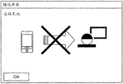
Figure 20 is the diagram of the example of diagram fault screen;
Figure 21 is the diagram that is shown in the example of the logon screen that shows on the display of information provider unit;
Figure 22 is the diagram that is shown in the example of the navascreen that shows on the display of information provider unit;
Figure 23 is the diagram for the step that the processing before the demonstration Data Acquisition Program that is used for transmission terminal is started by information provider unit is described;
Figure 24 is the diagram that is shown in the example of the fault screen that shows on the display of information provider unit;
Figure 25 shows the process flow diagram of the step of data acquisition process for diagram;
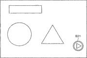
Figure 26 selects the diagram of the example of screen for the diagram file;
Figure 27 A is the diagram that is shown in the example of the display screen that shows on the display of information provider unit;
Figure 27 B is the diagram that is shown in the example of the display screen that shows on the display of information provider unit;
Figure 28 is used for explanation sends the step of the processing that shows data from information provider unit diagram for diagram;
Figure 29 A is the diagram of the example of the display screen that shows on the display of pictorial information generator;
Figure 29 B is the diagram of the example of the display screen that shows on the display of pictorial information generator;
Figure 30 switches the diagram of the step of the processing that shows the data transfer source for being used for explanation; And
Figure 31 stops to show the diagram of step of the processing of data transfer for being used for explanation.
Embodiment
Below with reference to accompanying drawing embodiment is described in detail.
Fig. 1 is the diagram of diagram according to the example of the configuration of the transmission system of embodiment.At first the general introduction with reference to 1 couple of this embodiment of figure is described.Notice, will describe in this embodiment the transmission system that can carry out teleconference between by the position of remote separation.
The example of transmission system comprises: data providing system, and one of them transmission terminal arrives another transmission terminal via the unidirectional transmission content-data of transmission and management system; And communication system, wherein via transmission and management system mutual transmission information, sensation etc. between a plurality of transmission terminals.This communication system is the system that is used for via communications management system (corresponding to " transmission and management system ") mutual transmission information, sensation etc. between a plurality of communication terminals (corresponding to " transmission terminal "), and its example comprises TeleConference Bridge, video-telephone system, audioconference system, voice calling system and personal computer (PC) Screen Sharing System.
In this embodiment, the supposition TeleConference Bridge as the example of communication terminal transmission system, transmission and management system and transmission terminal is described as example and the teleconferencing terminal of communications management system as example, the teleconference management system of communication system.Therefore, be applied to equally in the communication system or transmission system except TeleConference Bridge according to information provider unit of the present invention and transmission system.Notice that TeleConference Bridge also can be known as video conferencing system.
In this embodiment, " transmission terminal 10 " will be used to refer to a certain transmission terminal (10aa, 10ab ...), " display 130 " will be used to refer to a certain display (130aa, 130ab ...), " information provider unit 30 " will be used to refer to a certain information provider unit (30a, 30b ...), " relay 40 " will be used to refer to some relays (40a, 40b, 40c, 40d), and " router 60 " will be used to refer to a certain router (60a, 60b, 60c ...).The quantity of terminal and device is not limited to the example among Fig. 1.
The conferencing information that transmission terminal 10 sends such as view data (will in the view data of catching of describing after a while and show data) and voice data is used for engaging in the dialogue with other transmission terminal 10.Particularly, dialogue in this embodiment not only comprises the sending/receiving of voice data, also comprises the sending/receiving of view data.
Note, by using in the dialogue (teleconference) that transmission terminal 10 carries out, the example of conferencing information comprise the things (for example outturn sample) of presenting to the participant, participant profile, distribution material and be not to distribute but the images of materials that the display device by the projector (display 130 that is different from transmission terminal 10) on device shows.Therefore, conferencing information refers to the information that the participant can have in the meeting of participant's face-to-face talk.Described conferencing information can comprise view data and voice data the two or at least one of them.When conferencing information only comprised view data, for example, participant's speech will present as the captions in the image.Although what will describe in this embodiment is that the image of view data is the situation of moving image, however described image can be still image or can comprise moving image and still image the two.
MFP80 has copy function, scan function, printing function, facsimile function and document case function.MFP80 in this embodiment has scan function and printing function and the arbitrarily MFP that do not possess other any function, perhaps can be scanner.
The various data of data administrator 90 storages such as the data that generated by MFP80.In response to the request from information provider unit 30, data administrator 90 also sends the data that are stored in wherein and arrives information provider unit 30 etc.
In this embodiment, the user takes information provider unit 30 near MFP80 to, and the file that will scan of command M FP80 scanning self-information generator in future 30 is so that the file that MFP80 scanning will scan.The data of the file that the precalculated position storage of MFP80 in data administrator 90 draws from scanning, and the stored position information that will represent to store the position in the data administrator 90 of described data sends to information provider unit 30.Information provider unit 30 receives described stored position informations and the filename of described data and stored position information is registered in wherein the file management table associated with each otherly.The operation that information provider unit 30 is carried out in response to the user subsequently, the data that visit data management devices 90 is stored with the memory location that is received in data administrator 90.The user takes information provider unit 30 to subsequently near transmission terminal 10, selects the data that will share from information provider unit 30, and sends selected data to transmission terminal 10.Transmission terminal 10 is shared described data in electronic meeting.
Transmission and management system 50 is with integration mode management transmission terminal 10 and relay 40.Particularly, transmission and management system 50 is with the communications status of integration mode management transmission terminal 10 and relay 40.For example, transmission and management system 50 and transmission terminal 10 and relay 40 mutual registrations with the transmission terminal 10 of management in transmission system 1, Termination ID and IP address with management transmission terminal 10, statistics with the management use, informing other transmission terminals 10 that can communicate with to each transmission terminal 10, with use state of obtaining each transmission terminal 10 etc.Transmission and management system 50 also to each other transmission terminal 10 inform each transmission terminal 10 state (such as do not connect, login or in meeting).
Router 60 is better than the route device of the route of sending/receiving conferencing information (view data and voice data) most for internet and selection.
Program provides system 70 to comprise unshowned hard disk (HD), it has therein being used for of storage so that transmission terminal 10 is implemented various functions or so that transmission terminal 10 program that use as various device, that be used for transmission terminal, and the program for transmission terminal of can sending is to transmission terminal 10.The HD that program provides system 70 also therein storage be used for information provider unit, be used for so that information provider unit 30 is implemented various functions or so that the program that information provider unit 30 uses as various device, and the program for information provider unit of can sending is to information provider unit 30.The HD that program provides system 70 also therein storage be used for relay so that relay 40 is implemented different functions or so that the program that relay 40 uses as various device, and the program for relay of can sending is to relay 40.In addition, the HD that program provides system 70 also therein storage be used for dialogue management so that transmission and management system 50 is implemented difference in functionalitys or so that the program that transmission and management system 50 uses as various device, and the program for dialogue management of can sending is to transmission and management system 50.
Transmission terminal (10aa, 10ab), relay 40a are connected the mode that can communicate mutually and are connected via LAN2a with router 60a.Transmission terminal (10ba, 10bb), relay 40b are connected the mode that can communicate mutually and are connected via LAN2b with router 60b.LAN2a is connected the mode that can communicate betwixt and is connected via the leased circuit 2ab that comprises router 60ab and be based upon among the presumptive area A with LAN2b.For example, regional A is Japan, and LAN2a is based upon the office in Tokyo and the office that LAN2b is based upon Osaka.
Simultaneously, transmission terminal (10ca, 10cb), MFP80, relay 40c are connected the mode that can communicate mutually and are connected via LAN2c with router 60c.Transmission terminal (10da, 10db), relay 40d are connected the mode that can communicate mutually and are connected via LAN2d with router 60d.LAN2c is connected the mode that can communicate betwixt and is connected via the leased circuit 2cd that comprises router 60cd with LAN2d, and is based upon among the predetermined regional B.For example, regional B is in the U.S., and LAN2c is based upon in the office in New York and LAN2d is based upon in the washingtonian office.Zone A be connected B and connect respectively in the mode that can communicate betwixt via Internet 2 i by router (60ab, 60cd).
As shown in Figure 1, MFP80 belongs to regional B, but also can be configured to belong to regional A.
In this embodiment, LAN2a, LAN2b, leased circuit 2ab, Internet 2 i, leased circuit 2cd, LAN2c and LAN2d consist of the communication network 2 of this embodiment.Communication network 2 can comprise the part of radio communication and use the part of wire communication.
Next, will the hardware configuration of above-mentioned transmission terminal 10, information provider unit 30 and MFP80 be described.The hardware configuration of transmission terminal 10 at first, is described with reference to Fig. 2.
Fig. 2 is the example block diagram of the hardware configuration of transmission terminal 10.As shown in Figure 2, transmission terminal 10 comprises the CPU (central processing unit) (CPU) 101 of the integrated operation of controlling transmission terminal 10, has the therein ROM (read-only memory) (ROM) 102 of the various programs of storage, the random access storage device (RAM) 103 that uses as the perform region of CPU101, according to the control of CPU101 from/to the solid-state drive (SSD) 105 of the various data of flash memory 104 read/writes, control from/carry out the media drive 107 of the read/write of various data to the recording medium 106 such as storage card, action button 108 such as the cursor of the address that is used for selection transmission terminal 10 or other operations, be used for opening/closing transmission terminal 10 power supply power switch 109 and by send the network interface (I/F) 110 of data with communication network 2.
Although display 130 is connected to display I/F118 in this embodiment, embodiment is not limited to this, but display I/F118 alternately is connected to the video output device that comprises the projection arrangement such as projector.
As shown in Figure 2, transmission terminal 10 further comprises such as the address bus and the bus line the data bus 120 that are used for being electrically connected to said modules.
Note, recording medium 106 can be attached to transmission terminal 10/removable from transmission terminal 10.Storer is not limited to flash memory 104, and can be according to the control of CPU101 with data from its read/to its any nonvolatile memory that writes, such as electrically erasable ROM (EEPROM).The display unit of display 130 for being made of liquid crystal or organic EL, it shows the image of subject, the icon of operation etc.
The program of carrying out at transmission terminal 10, be used for transmission terminal can be with computer readable recording medium storing program for performing record and the distribution at all recording mediums 106 described above and so on of the form of the file that can be mounted or carry out.The program that is used for transmission terminal can be stored in ROM102, rather than on the flash memory 104.Alternately, program can provide system 70 to download and be recorded on flash memory 104 or the recording medium 106 from program via network I/F110.
Next, the hardware configuration with reference to 3 pairs of information provider units 30 of figure is described.Fig. 3 is the diagram of example of the hardware configuration of information provider unit 30.As shown in Figure 3, information provider unit 30 comprises: the CPU301 of the integrated operation of control information generator 30, ROM302 with various programs that are used for driving CPU301 of therein storage, RAM303 with the perform region that acts on CPU301, the hard disk (HD) of the various data of storage such as being used for the program of information provider unit, control the hard drive (HDD) 305 that various data read/write to HD304 from HD304 according to the control of CPU301, made by the display device such as liquid crystal or organic EL, demonstration is such as cursor, menu, window, the display 306 of the various demonstration information segments of text and image and so on, be used for by using communication network 2 to send the network I/F307 of data, be used for selecting and carrying out various instructions, select subject to be processed, the action button 308 of mobile cursor etc., by select and carry out different instruction with touch panel, select subject to be processed, the guidance panel 309 of mobile cursor etc.; Control from/read or the media drive 311 of data writing to the recording medium 310 such as flash memory; And the external device (ED) connection I/F315 that is used for connecting external device (ED).
Various external device (ED)s can be connected to external device (ED) by USB cable etc. and connect I/F315.Although described in this embodiment the example of the configuration that information provider unit 30 is connected with transmission terminal 10 by the first communication I/F312 and second communication I/F313, yet this configuration is not limited to this.For example, information provider unit 30 can be configured to connect I/F315 by external device (ED) and is connected with transmission terminal 10 by USB cable etc.
As shown in Figure 3, information provider unit 30 further comprises be used to the bus line such as address bus and data bus 314 that is electrically connected on the said modules.Notice that recording medium 310 can be attached to transmission terminal 10/removable from transmission terminal 10.
The program that is used for information provider unit of carrying out at information provider unit 30 can be recorded and distributes at the computer readable recording medium storing program for performing of all recording mediums 310 described above and so on the document form that can be mounted or carry out.The program that is used for information provider unit can be stored in ROM302 rather than HD304.Alternately, program can provide system 70 to download and is recorded on the computer readable recording medium storing program for performing such as HD304 or recording medium 310 from program via network I/F307.
It all is server unit that relay 40, transmission and management system 50, program provide system 70 and data administrator 90, and has the allocation of computer identical with above-mentioned information provider unit 30 (not shown).Provide each function that is stored in the program in the storage medium that comprises in the current device by execution or each device is provided from the program that program provides system 70 to provide of the CPU that comprises in system 70 and the data administrator 90 in relay 40, transmission and management system 50, program.Relay 40, transmission and management system 50, program provide system 70 and data administrator 90 not to need to comprise the above-mentioned first communicate by letter I/F312 and second communication I/F313.
Next, will the hardware configuration of MFP80 be described.Fig. 4 is the explanatory according to the MFP hardware configuration of this embodiment.As shown in Figure 4, MFP80 has following configuration, and its middle controller 510, scanning element 82 are connected with print unit via the connection of peripheral unit interconnection (PCI) bus.Controller 510 for the control of the whole MFP80 of control and reproduction, communicate by letter and from the controller of the input of operating unit 520.Scanning element 82 or print unit 81 comprise the data processing section of carrying out the error-diffusion method that is used for binaryzation, the gamma conversion that is used for correction gradient etc.Operating unit 520 has in liquid crystal display (LCD) and shows the document image information of the file that read by scanning element 82 etc. and receive the operation display unit 520a of the input that the operator makes and the keyboard unit 520b that receives the keyboard input of being made by the operator by touch panel.
Can between these functions, switch by the application switching key of operating unit 520 according to document case function, copy function, printing function, scan function and the facsimile function of the MFP80 of this embodiment and to select.When selecting the document case function, enter the document case pattern; When selecting printing function, enter printer mode; When selecting scan function, enter scan pattern; And when selecting facsimile function, enter the facsimile recorder pattern.
CPU511 controls whole digital MFP80, has the chipset that comprises NB513, MEM-P512 and SB514, and is connected to other device via this chipset.
NB513 is connected the bridge that is connected for being used for CPU511 and MEM-P512, SB514 with the AGP bus, and have control from/to Memory Controller and PCI master's device and the AGP target of the read/writes such as MEM-P512.
MEM-P512 is system storage, and it is as being used for storage program and data storage device, being used for extender and data storage device, being used to the storer of the reproduction such as printer and using, and comprises ROM512a and RAM512b.ROM512a be to be used for the program of storage control CPU511 operation and the ROM (read-only memory) that the data storage device uses, and RAM512b is writing and readable storer of being used for extender and data storage device, being used for that the storer of printer reproduction etc. uses.
The bridge of SB514 for being used for NB513 and PCI device are connected with peripheral unit.SB514 is connected to NB513 via pci bus, and network interface (I/F) unit 580 grades also are connected to this pci bus.
ASIC516 processes the integrated circuit (IC) of using for the image that is used for having the hardware element of processing for image, and as AGP bus 515, pci bus, HDD518 and MEM-C517 being connected the bridge of each connection.ASIC516 comprise PCI target and AGP master's device, as the Memory Controller of the arbiter (ARB) of the core of ASIC516, control MEM-C517, by using the conversion image data such as hardware logic etc. a plurality of DMA controllers (DMAC) and via the PCI unit of pci bus the transmission of data between print unit 81 and scanning element 82.ASIC516 is connected with second communication I/F585 with fax control module (FCU) 530, USB (universal serial bus) (USB) 540, IEEE1394 (IEEE 1394) interface, the first communication I/F583 via pci bus.Notice that described the first communication I/F583 is the communication interface with the NFC compatibility, described second communication I/F585 is the communication interface with bluetooth (registered trademark) communication standard compatibility.
MEM-C517 is for as the buffer of the image that is used for copy and the local storage that the code cache device uses, and HDD518 is used for the storer of program, accumulation character font data and the accumulation list of the operation of control CPU511 for being used for accumulation image data, accumulation.
Next, will the functional configuration of above-mentioned transmission terminal 10, information provider unit 30 and MFP80 be described.Fig. 5 is the functional configuration block diagram of transmission terminal 10, information provider unit 30 and MFP80.
As shown in Figure 5, transmission terminal 10 comprises sending/receiving unit 11, operation input receiving element 12, logging request unit 13, image capturing unit 14, audio frequency input block 15, audio output unit 16, indicative control unit 17, reduction unit 18, storage/reading processor 19, external information determining unit 20, NFC sending/receiving unit 21 and bluetooth sending/receiving unit 22.These unit are to be embodied as the function of following work or so that the equipment of following work: according to the program that is used for transmission terminal of in RAM103, expanding by from the command operating of CPU101 by random component shown in Figure 2.Transmission terminal 10 also comprises the storage unit 23 that makes up with SSD105 shown in Figure 2.
The sending/receiving unit 11 of transmission terminal 10 is by implementing from the instruction of CPU101 shown in Figure 2 and network I/F110 shown in Figure 2, and via communication network 2 to/from other terminal, device and the various data of system's sending/receiving (information).When setting up via relay 40 when communicating by letter as another transmission terminal 10 of another participant of meeting, sending/receiving unit 11 is the Termination ID of this transmission terminal 10 of registration in after a while with the admin table 231 of describing also, and this admin table 231 is stored in the storage unit 23 with engage in the dialogue with it Termination ID of transmission terminal 10 of (meeting) of management transmission terminal 10.The Termination ID of transmission terminal 10 is to allocate in advance to separately Hostname or the IP address of transmission terminal 10, and it is for can identify the separately identifying information fragment of transmission terminal 10.
Operation input receiving element 12 is by implementing from the instruction of CPU101 shown in Figure 2 and action button 108 and power switch 109 shown in Figure 2, and receives the various inputs that the operator by transmission terminal 10 makes.For example, in order to select transmission terminal 10 to carry out meeting, select cursor on meeting participant's the screen (not shown) to select the transmission terminal 10 that the participant by meeting uses and press when selecting button when the operator is used on the display 130 being used for of showing, operation input receiving element 12 receives the Termination ID of selected transmission terminal 10 or IP address as the participant of meeting.In addition, in order to change arrangement and the size (layout) that will be presented at the view data on the screen, operation input receiving element 12 receives the information that indication changes via action button 108 grades from current transmission terminal 10 operators.
Logging request unit 13 is by implementing from the instruction of CPU101 shown in Figure 2, and automatically sends the landing request information of request current transmission terminal 10 logins and the current IP address of current transmission terminal 10 to transmission and management system 50 by sending/receiving unit 11 via communication network 2.Notice that described landing request information is assumed that and includes at least Termination ID, and transmission and management system 50 management are from landing request information fragment and the IP address of each transmission terminal 10 transmission.Be set to when transmission terminal 10 powers on, automatically perform to the landing request information of transmission and management system 50 and the transmission of IP address.
Image capturing unit 14 is by implementing from CPU101 shown in Figure 2 with from the instruction of camera shown in Figure 2 113 and camera I/F114, and catch the image that comprises as the participant's of subject etc. meeting room, and output is by catching the view data of obtaining.
Audio frequency input block 15 is for by implementing from the instruction of CPU101 shown in Figure 2 and audio frequency I/O I/F117 shown in Figure 2, and near the sound the transmission terminal 10 that will be collected by microphone 15 be converted to sound signal to generate voice data.Audio output unit 16 is by implementing from CPU101 shown in Figure 2 and audio frequency I/O I/F117 shown in Figure 2, and the voice data that will send from other transmission terminals 10 etc. outputs to loudspeaker 116 with by loudspeaker 116 output audios.
Indicative control unit 17 is by implementing from the instruction of CPU101 shown in Figure 2 and display I/F118 shown in Figure 2, sends view data and shows data to display 130 and carry out and control to show these data.
Reduction unit 18 is by implementing from the instruction of CPU101 shown in Figure 2 and network I/F110 shown in Figure 2, and carries out and process so that a plurality of relays 40 are reduced to a relay 40.Particularly, reduction unit 18 calculated response are in the transmission information that receives from relay 40, to a certain transmission information of each relay 40 at confirmation (ACK) transmission required time (take millisecond as unit) before, and by be chosen in wanting of calculating carry out relaying in the time the shortest in the seeking time relay 40 as will with relay 40 come from a plurality of relays 40, to select a relay 40.
Storage/reading processor 19 is by implementing from the instruction of CPU101 shown in Figure 2 and SSD10 shown in Figure 2, and carries out and process with store various kinds of data in storage unit 23 and read in the various data of storage in the storage unit 23.
Storage unit 23 store therein be used for management to become meeting the participant other transmission terminal 10 terminal identity (ID) admin table 231 (referring to Fig. 6) and wherein storage for the authentication table 232 (referring to Fig. 7) of the authentication information (user ID and password) that determines whether to allow to use information provider unit 30.When information provider unit 30, the driver etc. that is used for data transmission are installed current memory cell 23, storage unit 23 is also stored the demonstration Data Acquisition Program 233 that the CPU301 by information provider unit 30 carries out therein.Show that Data Acquisition Program 233 is the program for the demonstration data capture unit 35 that is implemented in information provider unit 30.
Fig. 6 is the diagram that is shown in the example of the admin table 231 of storage in the storage unit 23.As shown in Figure 6, in admin table 231, register explicitly the Termination ID of the transmission terminal 10 that will become the meeting participant with the data label.At the row that are used for storage terminal ID, the Termination ID (transmission terminal 10aa, transmission terminal 10ba, transmission terminal 10ca) of registration meeting participant's transmission terminal 10.The data label is managed the separately management label of Termination ID for being used for, and is used for assigning from having the separately view data (view data of catching) of transmission terminal 10 distributions of Termination ID to the viewing area, and this will be described below.
Fig. 7 is the diagram that is shown in the example of the authentication table 232 of storage in the storage unit 23.As shown in Figure 7, the row (password ID row) that authentication table 232 comprises the row (user ID row) of wherein storing user ID and wherein stores password, and store therein user ID and the password of the authentication user of information provider unit 30 with being associated with each other.Suppose that the authentication information of the set that comprises user ID and password is distributed to the authentication user of information provider unit 30 in advance.
Later with reference to figure 5, external information determining unit 20 is implemented by CPU101 shown in Figure 2, and determines whether the information provider unit 30 sending/receiving data from transmission terminal 10 outsides again.
NFC sending/receiving unit 21 is implemented with the first instruction of communicating by letter I/F111 shown in Figure 2 by CPU101 shown in Figure 2, and carries out contactless communication (hereinafter middle finger NFC communicates by letter) with the NFC sending/receiving unit 31 (hereinafter will describe) of information provider unit 30 according to the NFC standard by contactless communication.
Note, the shorter communication range sending/receiving data of distance of the second communication I/F112 (bluetooth sending/receiving unit 22) of another communication unit are communicated by letter to be compared in NFC sending/receiving unit 21 by non-contact type wireless, more specifically, with the communication range of the most about 10cm.Because according to the data transmission rate (being 424kbps to the maximum) of the contactless communication of the NFC standard of being carried out by NFC sending/receiving unit 21 less than the data transmission rate (being 24Mbps to the maximum) according to bluetooth (registered trademark) communication standard of being carried out by bluetooth sending/receiving unit 22, so be assumed to be data transfer for relatively small amount according to the contactless communication of NFC standard.Note, the communication standard that is used for NFC sending/receiving unit 21 does not need to be defined in NFC, but so long as relatively short-range radio communication just can realize functional unit according to another communication standard as the first communication I/F111 by using according to the communication interface of this communication standard, in the beguine communication range less according to the distance of the radio communication (will be explained hereinafter) of bluetooth (registered trademark) communication standard, be possible namely.
When information provider unit 30 during near the communication range of NFC sending/receiving unit 21, NFC sending/receiving unit 21 is carried out and the communicating by letter of the NFC sending/receiving unit 31 (will describe after a while) of information provider unit 30, receive from NFC sending/receiving unit 31 authentication informations that send and send foundation according to the necessary connection configuration information of bluetooth (registered trademark) communication standard (hereinafter middle finger Bluetooth communication) to NFC sending/receiving unit 31.Notice that this connections configuration information refers to by the necessary information of bluetooth sending/receiving unit 22 execution radio communications, and comprise blue-tooth device (BD) address, be assigned to the password of second communication I/F112 etc.Connect configuration information and can be the form that the form held NFC sending/receiving unit 21 or NFC sending/receiving unit 21 read from second communication I/F112.
Bluetooth sending/receiving unit 22 is implemented by the instruction of CPU101 shown in Figure 2 and second communication I/F112 shown in Figure 2, and carries out radio communication with the information provider unit 30 according to bluetooth (registered trademark) communication standard as short-range communication unit.Bluetooth sending/receiving unit 22 is than the NFC sending/receiving unit 21 sending/receiving more data (maximum 24Mbps) that adopt according to the contactless communication scheme of NFC standard.Bluetooth sending/receiving unit 22 can be approximately 10 meters to 100 meters device space from using, and this communication range is larger than the distance of NFC sending/receiving unit 21.
For to/from information provider unit 30 sending/receiving data, Bluetooth communication is set up by the connection configuration information and the information provider unit 30 that use NFC sending/receiving unit 21 to send to information provider unit 30 in bluetooth sending/receiving unit 22.
Although will be used as second communication I/F112 with the I/F that communicates by letter of bluetooth (registered trademark) communication standard compatibility in this embodiment, yet communication I/F is not limited to this, and can use according to the communication I/F in the Wireless Fidelity (WiFi) of another standard such as the IEEE802.11a/IEEE802.11B standard.In this case, the WiFi sending/receiving unit corresponding with bluetooth sending/receiving unit 22 can by be used for the sending/receiving data, according to the network board of IEEE802.11a/b/g/n be used for control and consist of according to the communication control unit (communication control program) of the sending/receiving of the foundation of the radio communication of IEEE802.11a/b/g/n and data.
Alternately, when the distance between the device in ultra broadband (UWB) communication plan is 3 meters or more in short-term, the configuration that communicates according to Wireless USB Specification that can use that the 480Mbps that can carry out being equal to wired USB2.0 communicates by letter.In this case, the Wireless USB sending/receiving unit corresponding with bluetooth sending/receiving unit 22 can be by according to the USB device of the Wireless USB Specification that is used for the sending/receiving data be used for control and consist of according to the communication control unit (communication control program) of the sending/receiving of the foundation of the radio communication of UWB communication plan and data.
Next, the descriptor generator 30.As shown in Figure 5, information provider unit 30 comprises sending/receiving unit 320, NFC sending/receiving unit 31, bluetooth sending/receiving unit 32, operation income receiving element 33, indicative control unit 34, shows data capture unit 35, indicated data communication unit 36, storage/reading processor 37 and FCU file control unit 39.These unit are for implementing with the function of following work or so that the equipment of following work: according to the program that is used for information provider unit of RAM303 expansion by from the command operating of CPU301 by random component shown in Figure 3.This information provider unit 30 also comprises the storage unit 38 of being set up by the HDD305 shown in Fig. 3.
Sending/receiving unit 320 is implemented by the instruction of CPU301 shown in Figure 3 and network I/F307 shown in Figure 3, and via communication network 2 to/from other-end, device and the various data of system's sending/receiving.For example, sending/receiving unit 320 is from data administrator 90 receive datas.
NFC sending/receiving unit 31 is implemented with the first instruction of communicating by letter I/F312 shown in Figure 3 by CPU301 shown in Figure 3, and by carrying out contactless communication according to the contactless communication of NFC standard and the NFC sending/receiving unit 21 of transmission terminal 10 and the NFC sending/receiving unit 85 of MFP80.
In addition, when current information generator 30 during near the communication range of the NFC sending/receiving unit 21 of transmission terminal 10, the also various data of sending/receiving (information) of communicating by letter with the NFC of the NFC sending/receiving unit 21 of transmission terminal 10 are set up in NFC sending/receiving unit 31.Particularly, when having set up when communicating by letter with the NFC of the NFC sending/receiving unit 21 of transmission terminal 10, NFC sending/receiving unit 31 sends the connection configuration information of being held by the NFC sending/receiving unit 21 of transmission terminal 10 to transmission terminal 10 and reception by the authentication information of user's input of current device.In this embodiment, the authentication information that is input to information provider unit 30 by the user of information provider unit 30 turns back to transmission terminal 10 and communicates, so that 10 pairs of authentication informations of transmission terminal carry out authentication.
Similarly, when current information generator 30 during near the communication range of the NFC sending/receiving unit 85 of MFP80, NFC sending/receiving unit 31 is set up NFC with the NFC sending/receiving unit 85 of MFP80 and is communicated by letter, and the various data (information) of sending/receiving.Particularly, when with the NFC connection setup of the NFC sending/receiving unit of MFP80, NFC sending/receiving unit 31 sends information and the function setting information using authentication ID and functional identity, the communications setting information of MFP80 and be used for communicating by letter by 32 foundation of bluetooth sending/receiving unit of being used for from information provider unit 30.
Bluetooth sending/receiving unit 32 is by implementing from the instruction of CPU301 shown in Figure 3 and second communication I/F313 shown in Figure 3, and when setting up with the communicating by letter of the bluetooth sending/receiving unit 22 of transmission terminal 10, the demonstration data that transmission is obtained by the demonstration data capture unit 35 that will be described below are to transmission terminal 10.Bluetooth sending/receiving unit 32 also receives the information of the shared state of indicated number data etc. from transmission terminal 10.In addition, when setting up with the communicating by letter of the bluetooth sending/receiving unit 86 of MFP80, bluetooth sending/receiving unit 22 is from MFP80 reception view data.
Fig. 8 is the diagram for the communication range that the radio communication that connects transmission terminal 10 and information provider unit 30 is described.Fig. 9 is the diagram for the communication range that the radio communication that connects MFP80 and information provider unit 30 is described.
In Fig. 8 and Fig. 9, all communication range A11 by the indication of chain doublet represent the communication range according to the NFC standard, that is, the possible near-field communication scope of communication between NFC sending/receiving unit 21 and the NFC sending/receiving unit 31 and between NFC sending/receiving unit 85 and the NFC sending/receiving unit 31 wherein.In addition, the communication range A12 representative that is illustrated by the broken lines is according to the communication range of bluetooth (registered trademark) communication standard, the i.e. possible near-field communication scope of communication between bluetooth sending/receiving unit 22 and bluetooth sending/receiving unit 32 and bluetooth sending/receiving unit 86 and the bluetooth sending/receiving unit 32.In this manner, communication range A12 has larger scope, and it is possible wherein allowing the communication of the distance longer than communication range A11.
As mentioned above, in case enter communication range A11, being connected with NFC sending/receiving unit in NFC sending/receiving unit 21 and is connected with NFC sending/receiving unit and automatically sets up NFC communication and transmission authentication information and be connected configuration information in NFC sending/receiving unit 85.Afterwards, when transmission terminal 10 and MFP80 accepted authentication information, being connected with bluetooth sending/receiving unit in bluetooth sending/receiving unit 22 and is connected with bluetooth sending/receiving unit by using the connection configuration information that has exchanged to set up Bluetooth communication in bluetooth sending/receiving unit 86.
In this manner, between transmission terminal 10 and the information provider unit 30 and the necessary connection configuration information of the Bluetooth communication between MFP80 and the information provider unit 30 communicate by letter to exchange by the NFC that allows simple data sending/receiving.In addition, only by information provider unit 30 being taken to the transmission terminal 10 near MFP80, the user of information provider unit 30 can be transmitted for the Bluetooth communication necessary information of foundation with transmission terminal 10 or MFP80.In this manner, can identify the transmission terminal 10 or the MFP80 that communicate, and need not concrete operations and can enable Bluetooth communication, this has increased convenience.
Again later with reference to figure 5, operation input receiving element 33 is by implementing from CPU301 shown in Figure 3 and action button 308 shown in Figure 3 and the instruction of guidance panel 309, and receives the input of being made by the user.
Show that data capture unit 35 implements by the demonstration Data Acquisition Program cooperation of the described CPU301 of Fig. 3 and storage in the storage unit 23 of transmission terminal 10, and obtain demonstration data about the various information that show at display 306 by indicative control unit 34.
Indicated data communication unit 36 is by implementing from the instruction of CPU301 shown in Figure 3 and second communication I/F313 shown in Figure 3, and sends by showing that demonstration data that data capture unit 35 obtains are to transmission terminal 10 via bluetooth sending/receiving unit 32.Indicated data communication unit 36 also basis change in this state receives the various information that send from transmission terminal 10.
Storage/reading processor 37 is by implementing from the instruction of CPU301 shown in Figure 3 and HDD305 shown in Figure 3, and carries out and be used for store various kinds of data is used for reading in the various data of storage unit 38 storages in storage unit 38 neutralizations processing.Storage unit 38 is stored data (hereinafter middle finger material data) in advance therein, such as the material that will share in meeting, be used for the various programs (word processor, spreadsheet, demonstration) of display material data etc.Material data comprises by data MFP80 scanning and that receive.
FCU file control unit 39 is as control module, and the spanned file admin table, and the stored position information that wherein is used for one or more data slots of receiving from MFP80 is associated with filename as the identifying information of the data of storage unit 38.In file management table, each of the filename of one or more data slots all is associated with stored position information.
Figure 10 is the explanatory of the example of diagram file management table.In current embodiment, use a path description stored position information and filename, this path is associated with the memory location of data and filename.Stored position information be comprise data be stored in wherein device and the information of the data storage position in this device.In this embodiment, tentation data is stored in the data administrator 90.In Figure 10 in the example of " http://dataserver.xxx.co.jp/conference/doc/strategy.pdf ", " https: //dataserver.xxx.co.jp " be the URL as the data administrator 90 of data storage device wherein."/conference/doc " is illustrated in the memory location in the storage unit of data administrator 90, and the filename of " strategy.pdf " expression data.Therefore, because the data storage positional information is included in the device of wherein storing data and the information that represents access path of data in this device, so information provider unit 30 can be by the memory location of reference paper admin table identification file.
Again later with reference to figure 5, above-mentioned indicative control unit 34 is presented at the tabulation of data file of one or more data slots of registering in the file management table with the filename of the data that allow the user to select by operation input receiving element 33 will to be shared at display 306.Sending/receiving unit 320 receives the data of selected filename from the memory location by the data administrator 90 of stored position information indication via Internet 2 i.Indicative control unit 34 shows the data that receive.Indicated data communication unit 36 also sends to transmission terminal 10 via bluetooth sending/receiving unit 32 with the data that receive.
Next, will the functional configuration of MFP80 be described.MFP80 comprises sending/receiving unit 800, scanning element 82, print unit 81, fax transmission/reception unit 83, data processor 84, NFC sending/receiving unit 85, bluetooth sending/receiving unit 86, uses permission determining unit 87, authenticating unit 88, authorization data storage unit 89 and File Control Procedure storage unit 801.
Sending/receiving unit 800 is by implementing from the instruction of CPU511 and network I/F unit 580, and via communication network 2 to/from other-end, device or the various data of system's sending/receiving.For example, sending/receiving unit 800 to/from data administrator 90 and the various data of information provider unit 30 sending/receivings.
NFC sending/receiving unit 85 is according to the contactless two-way communication of above-mentioned NFC wireless communication standard execution with information provider unit 30, and more specifically, it has reader/writer or wherein has for the function from the label of the communication control program of the NFC sending/receiving unit 31 contactless ground reading informations of information provider unit 30.NFC sending/receiving unit 85 comes the sending/receiving data with the shorter communication distance of communication distance of the bluetooth sending/receiving unit 86 that is compared to another communication unit by non-contact type wireless communication, more specifically, with about 0 to the communication distance more than 10 centimetres.Owing to be lower than data transmission rate (1 to 2Mbps) according to the radio communication of bluetooth (registered trademark) communication standard of being carried out by bluetooth sending/receiving unit 86 according to the data transmission rate (100 to 400kbps) of the contactless communication of the NFC standard of being carried out by NFC sending/receiving unit 85, thus according to the contactless communication of NFC standard for relatively few data transfer.Note, the unnecessary NFC that is limited to of communication standard that is used for NFC sending/receiving unit 85, can also be other communication standards such as infrared data communication (IrDA), as long as radio communication is in relatively short distance, that is, communication range is possible less than the communication range according to the radio communication of bluetooth (registered trademark) communication standard that will be described below.
When information provider unit 30 appears in the communication range of NFC sending/receiving unit 85, NFC sending/receiving unit 85 is by using the communication protocol identical with the communication protocol program of the NFC sending/receiving unit 31 that is used for information provider unit 30 to set up and the communicating by letter of the NFC sending/receiving unit 31 of information provider unit 30, and receives authentication ID, functional identity, communications setting information and the function setting information that sends from information provider unit 30.Notice that authentication ID is for being used for determining whether to allow to use the authentication information of the MFP80 that is indicated by information provider unit 30.Authentication ID is assigned to only information of information provider unit 30 or is used for the information that identification has the user of this information provider unit 30.When using the information that is used for the identification user, can use the information such as employee ID.The function information of the function of the functional identity MFP80 that to be representative used by information provider unit 30 requests, and in the time for example will using the printing function of MFP80, functional identity is set to print ID.In the time will using the scan function of MFP80, functional identity is set to " scans I D ".
Communications setting information is for carrying out the required initial settings information of radio communication by bluetooth sending/receiving unit 86.In this manner, the result that the NFC of the simple sending/receiving by allowing data communicates by letter to receive for the communications setting information of carrying out Bluetooth communication between information provider unit 30 and the MFP80 is, the user only needs information provider unit 30 taken near MFP80 and five any concrete operations and identifies the MFP80 of with it communication and enable Bluetooth communication, and this will increase convenience.Function setting information is the configuration information of indication according to the processing of function.For example, when printing ID and be set to functional identity, as print setting information arrange that ID " duplex printing " is set to that settings " are opened " or " pass " and as print setting information arrange that ID " layout " is set to that settings " are opened " or " pass " as function setting information.When scans I D is set to functional identity, is set to settings " 300 " dpi etc. and is used as function setting information as the ID " resolution " that arranges of scan setting information.
Authenticating unit 88 determines whether the authentication ID that is sent by information provider unit 30 is that the use of MFP80 is to the ID of its permission.Particularly, the identical authentication of carrying out whether of the authentication ID by the authentication ID that determines to be received by NFC sending/receiving unit 85 and storage in authorization data storage unit 89.
Use and allow determining unit 87 to determine that whether the functional identity that sent by information provider unit 30 allows the ID that uses as MFP80.Particularly, by obtain from authorization data storage unit 89 be associated with the authentication ID that is received by NFC sending/receiving unit 85 and functional identity with permission information and determine with permission whether obtain with permission information arrange to carry out authentication.
Bluetooth sending/receiving unit 86 communicates according to bluetooth (registered trademark) standard and information provider unit 30 contactlessly.Employing according to the bluetooth sending/receiving unit 86 of the radio communication system of bluetooth (registered trademark) scheme with than adopting the NFC sending/receiving unit 85 higher speed (1 to 10Mbps) according to the contactless communication scheme of NFC standard to come the larger data of sending/receiving.Even there is barrier, as long as the distance between the device is at 10 meters or shorter, just can adopt the bluetooth sending/receiving unit 86 according to the radio communication system of bluetooth (registered trademark) standard, and have beguine according to the larger communication range of the communication plan of NFC standard.
Particularly, bluetooth sending/receiving unit 86 is by consisting of such as blue tooth interface (I/F) and the communication control unit according to the transceiver of bluetooth (registered trademark) that are used for the sending/receiving data.Bluetooth (registered trademark) I/F carries out the data sending/receiving of the information provider unit 30 that is connected with MFP80.Communication control unit is following communication control program: be used for to/carry out before the information provider unit 30 sending/receiving data via bluetooth (registered trademark) I/F and the information provider unit 30 switched communication configuration informations of communicating by letter and according to the process of bluetooth (registered trademark) normalization radio communication.An only address information that is assigned to bluetooth (registered trademark) I/F is used as communications setting information.
Although the bluetooth sending/receiving unit 86 with bluetooth (R) compatibility is used to radio communication in this embodiment, yet the configuration be not restricted to this, and radio communication can according to such as IEEE802.11a/IEEE802.11b/IEEE802.11n/IEEE802.11g rather than the scheme of another standard of the so-called WLAN standard of bluetooth (registered trademark) standard carry out.In this case, the WLAN communication unit can by be used for the sending/receiving data according to IEEE802.11a/IEEE802.11b standard network plate and be used for control and consist of according to the communication control unit (communication control program) of the sending/receiving of the foundation of the radio communication of IEEE802.11a/IEEE802.11b and data.Alternately, when in the UWB communication plan between the device distance be 3 meters or more in short-term, can use the configuration of the radio communication of carrying out according to Wireless USB Specification that can communicate with the 480Mpbs that is equal to wired USB2.0.In this case, the Wireless USB communication unit can by be used for the sending/receiving data according to the UWB device of Wireless USB Specification and be used for the foundation of control radio communication and the communication control unit (communication control program) of the sending/receiving of data consists of.
Bluetooth sending/receiving unit 86 also communicates by letter with from information provider unit 30 received communication configuration informations by NFC, and when the Bluetooth communication set up according to the communications setting information that receives with information provider unit 30, bluetooth sending/receiving unit 86 comes the sending/receiving data according to functional identity.The data that send/receive can be view data, file data, text data and any other various types of data.
Scanning element 82 by such as charge-coupled image sensor (CCD) image collecting device come file reading.Can be by the next function that provides autofile to present to this scanning element 82 of automatic document feeder (ADF) be installed in scanning element 82.
The data that data processor 84 is processed the data that received by bluetooth sending/receiving unit 86 or will be sent by bluetooth sending/receiving unit 86 according to the functional identity that is received by NFC sending/receiving unit 85 and function setting condition.For example, when functional identity is " printing ID ", come data are carried out the image processing such as density and color adjustment, the layout processing such as single-side/double-side is printed etc. according to function setting information.For another example, when functional identity is " scans I D ", according to the function setting condition to the data carries out image processing that reads from scanning element 82, layout processing etc.
The data that fax transmission/reception unit 83 will be read by scanning element 82 via network and the data that send from information provider unit 30 send to another MFP, facsimile unit, client terminal etc.Fax transmission/reception unit 83 also receives the data that send from another MFP, facsimile unit or client terminal.
Whether the function that authorization data storage unit 89 storage is used for determining MFP80 operable authorization data.Figure 11 is the explanatory that is shown in the example of the data structure in the authorization data storage unit 89.Authorization data storage unit 89 is to each functional identity storage and the authentication ID that uses permission information to be associated.As shown in figure 11, authentication ID " individual 1 " be allowed to use the printing function of MFP80 and scan function the two.Authentication ID " individual 2 " is allowed to use the scan function of MFP80 but is not allowed to use its printing function.
File Control Procedure storage unit 801 storage file control programs.The program that be used for control the data that by MFP80 generated of File Control Procedure for being used by information provider unit 30.The program of File Control Procedure for sending to information provider unit 30 via communication network 2 and being carried out by information provider unit 30.
Figure 12 is the block diagram of the functional configuration of data in graph form management devices 90.As shown in figure 12, data administrator 90 comprises sending/receiving unit 91, server unit 92, storage/reading processor 93 and storage unit 94.
Sending/receiving unit 91 is by implementing from the instruction of CPU301 and network I/F307, and via communication network 2 to/from other-end, device or the various data of system's sending/receiving.For example, sending/receiving unit 91 to/from MFP80 and the various data of information provider unit 30 sending/receivings.
Storage/reading processor 93 is by implementing from the instruction of CPU301 and HDD305.Storage/reading processor 93 for example writes various data in storage unit 94, and for example reads various data from storage unit 94.
Storage unit 94 is implemented and store various kinds of data by HD304.For example, storage unit 94 is preserved the data that are associated from the data ID with being used for recognition data of MFP80 reception.
Next, will the data that will show at the display 130 of the transmission terminal 10 of above-mentioned transmission system 1 be described.The example of the data that the display 130 of transmission terminal 10 that will be on teleconference shows comprises the data of catching view data and sending from information provider unit 30 of being caught by camera 113 (comprising by data MFP80 scanning and that preserve at information provider unit 30).The view data of catching refers to the view data of being caught by the camera 113 of current transmission terminal 10 with other.Show that presentation of data is at the screen of display 306 demonstrations of information provider unit 30.
Figure 13 is the diagram in the example of the indicator screen of display 130 demonstrations of transmission terminal 10.Figure 13 illustrates the example that screen is divided into four zones, wherein the large zone (the first viewing area) from the left side of screen to the center is known as viewing area A21, and the zonule (the second viewing area) from the upper right corner of screen to the lower right corner is known as respectively A22 to A24.For example, in the situation of the screen of Figure 13 configuration, the participant with meeting is assigned to viewing area A21 to the view data of catching of the transmission terminal 10 of its microphone of speaking 115.The corresponding processing will be described below.
At first, the CPU101 of each transmission terminal 10 detected via the period 15 inputs of audio frequency input block, made speech by the operator of current transmission terminal 10, and when detecting this period, CPU101 sends to other transmission terminals 10 via relay 40 with the Termination ID of current transmission terminal 10.When transmission terminal 10 receiving terminal ID, the indicative control unit 17 of each transmission terminal 10 is with reference to admin table shown in Figure 6 231 and identify the data label that is associated with Termination ID.Indicative control unit 17 subsequently will from have with the transmission terminal 10 of the Termination ID that is associated of data label of identification receive catch view data assign and be shown to/at viewing area A21.In addition, indicative control unit 17 will receive from other transmission terminal 10 with Termination ID of being associated with other data labels catch view data from the A22 of viewing area, sequentially assign and be shown to/in the viewing area.Consequently, the current transmission terminal 10 that speech is provided catch the position that view data is arranged at more close display screen center, and show that with the size larger than other view data this can increase the visual of the current participant who speaks and show this participant in the mode that strengthens.Order to its viewing area A22 that assigns the data label to A24 is not particularly limited, and for example, the data label can sort according to ascending order or descending.
When showing that data send from information provider unit 30, indicative control unit 17 assign described demonstration data to viewing area A21 and with described demonstration data as among the A25 of viewing area, showing, and will from each transmission terminal 10 catch view data as shown in figure 14 from viewing area A22 sequentially assign and be shown to/in the viewing area.Consequently, show that data are arranged at the position at more close display screen center, and show with the size larger than other view data that this can increase to present the visual of material etc. and show in the mode that strengthens and presents material etc.
In addition, the example of aforementioned display device can be modified as follows.When showing that data send from information provider unit 30, show that data are assigned to whole screen (viewing area A2), in order to show that data show at whole screen shown in Figure 15.Then, when the input of pressing the predetermined button (for example, cursor key) of transmission terminal 10 and predetermined button as the user was operated input receiving element 12 and receives, indicative control unit 17 toggle screens were to the screen of Figure 13.Next, each user presses predetermined button, display screen just with Figure 14, Figure 15, Figure 13 ... the sequential loop switching.According to this pattern, even shown material data, according to circumstances can be seen from the view data of catching that other transmission terminals 10 people of other positions (namely) send.
Next, be used for information provider unit 30 command M FP80 formation image in the transmission system 1 that disposes as mentioned above to obtain the processing of data from MFP80 with being described in.
At first, be enabled in as meeting participant's user and being connected with command M FP80 between information provider unit 30 and the MFP80 form (scanning or print) image.Particularly, the indicative control unit 34 of information provider unit 30 shows logon screen shown in Figure 16 at display 306.The user keys in representative forms the instruction of image at logon screen authentication ID and functional identity.Figure 16 has described and has keyed in scans I D as functional identity and send the example of the instruction of MFP80 scan setting file as the instruction that forms image.
When authentication ID, functional identity and OK when logon screen is inputted, receive input by operation input receiving element 33.The user takes information provider unit 30 to subsequently near or contacts MFP80 in order to carry out NFC communication.In this process, when operation input receiving element 33 received input, indicative control unit 34 showed navascreen shown in Figure 17 with Dictating user so that information provider unit 30 contacts at display 306.In this navascreen, the filename that give the data that received by MFP80 also can be keyed in.Noting, can also be the not configuration of show navigator screen.Under this configuring condition, OK button shown in Figure 16 can be eliminated.
Then, radio communication and data are processed sets up following execution.Figure 18 and 19 is for illustrating by information provider unit 30 and the radio communication establishment step of MFP80 execution and the process flow diagram of data processing step.
At first, in information provider unit 30, NFC sending/receiving unit 31 determines whether set up (step S301) with the communicating by letter of NFC sending/receiving unit 85 of MFP80.If determine not have the communicating by letter of NFC sending/receiving unit 85 of foundation and MFP80, be that information provider unit 30 does not appear in the communication range (step S301: no), then process and get back to step S301, with its repetition until set up and the communicating by letter of the NFC sending/receiving unit 85 of MFP80.
Similarly, in MFP80, NFC sending/receiving unit 85 determines whether to have set up communicate by letter (the step S302) with the NFC sending/receiving unit 31 of information provider unit 30.If determine not have the communicating by letter of NFC sending/receiving unit 31 of foundation and information provider unit 30, be that information provider unit 30 does not appear in the communication range (step S302: no), then process and turn back to step S302, with its repetition until set up and the communicating by letter of the NFC sending/receiving unit 31 of information provider unit 30.
Next, if determine to have set up and the communicating by letter of the NFC sending/receiving unit 31 of information provider unit 30, be the communication range interior (step S302: be) that information provider unit 30 appears at MFP80, NFC sending/receiving unit 85 and information provider unit 30 switched communication configuration informations (step S303 and S304).Particularly, the NFC sending/receiving unit 85 solicited message generators 30 of MFP80 send communications setting information, and the NFC sending/receiving unit 31 of information provider unit 30 sends the communications setting information that is used for Bluetooth communication.In this process, information provider unit 30 can send authentication ID, functional identity and have the function setting information of communications setting information.
In information provider unit 30, bluetooth sending/receiving unit 32 determines whether to have set up communicate by letter (the step S305) with the bluetooth sending/receiving unit 86 of MFP80.If determined not have to set up communicate by letter (step S305: no) between the bluetooth sending/receiving unit 86 with MFP80, then processed termination.If determine to have set up communicate by letter (step S305: be) between the bluetooth sending/receiving unit 86 with MFP80, then FCU file control unit 39 sends the request of installation via bluetooth sending/receiving unit 32 and carries out installation (step S306) to MFP80.After a while to being installed into line description.
Simultaneously, in MFP80, bluetooth sending/receiving unit 86 determines whether to have set up communicate by letter (the step S307) with the bluetooth sending/receiving unit 32 of information provider unit 30.If determine not have to set up communicate by letter (step S307: no) with the bluetooth sending/receiving unit 32 of information provider unit 30, then processing termination.
If determine to have set up communicate by letter (step S307: be) with the bluetooth sending/receiving unit 32 of information provider unit 30, then the bluetooth sending/receiving unit 86 of MFP80 receives the request of installation, and data processor 84 is carried out (step S308) is installed.
The processing of information provider unit 30 and MFP80 among step S306 and the S308 will be described in detail in.The FCU file control unit 39 of information provider unit 30 sends the request of installation to MFP80 via bluetooth sending/receiving unit 32.When the bluetooth sending/receiving unit 86 of MFP80 received the installation request, data processor 84 sent the license of installation file control programs to information provider unit 30 via bluetooth sending/receiving unit 86.
In information provider unit 30, when bluetooth sending/receiving unit 32 receives the license of installing, FCU file control unit 39 is via the File Control Procedure storage unit 801 of bluetooth sending/receiving unit 32 access MFP80, read in the File Control Procedure of storage in the File Control Procedure storage unit 801 and with installation on the file system of information provider unit 30.In other words, File Control Procedure is stored in the storage unit 38.
When the installation finished on storage unit 38, the FCU file control unit 39 of information provider unit 30 is carried out the File Control Procedure (step S309) of storage in storage unit 38.Consequently, File Control Procedure is as the part of FCU file control unit 39.
Thereby, because the user of information provider unit 30 can take information provider unit 30 near MFP80 with at the timing of expectation installation file control program thereon, so File Control Procedure does not need to be installed in advance on the information provider unit 30, this will increase user's facility.
Next, the NFC sending/receiving unit 31 of information provider unit 30 sends authentication ID, functional identity and function setting information to the NFC sending/receiving unit 85 (step S310) of MFP80.Note, information provider unit 30 appears at situation in the communication range and refers to the user contacts the NFC sending/receiving unit 31 of information provider unit 30 with the NFC sending/receiving unit 85 of MFP80 situation, by guaranteeing like this to want the instruction of the MFP80 that uses to the user.
Simultaneously, the NFC sending/receiving unit 85 of MFP80 receives authentication ID, functional identity and the function setting information (step S311) that sends from the NFC sending/receiving unit 31 of information provider unit 30.Authenticating unit 88 obtains authentication ID (step S312) from authorization data storage unit 89.NFC sending/receiving unit 85 will send to from the authentication ID that authorization data storage unit 89 is obtained information provider unit 30 (step S313).Authenticating unit 88 will compare to determine whether to allow from authorization data storage unit the authentication ID that obtains and the authentication ID that sends from information provider unit 30 use (step S314) of MFP80.If determine not allow the use of MFP80, the authentication ID that namely receives is not stored in (step S314: no) in the authorization data storage unit 89, then processes stopping.
In information provider unit 30, NFC sending/receiving unit 31 receives the authentication ID (step S315) that sends from MFP80.NFC sending/receiving unit 31 determines whether to allow the use (step S316) of MFP80 based on the authentication ID that receives.If based on the use (step S316: be) that the authentication ID that receives determines to allow MFP80, then process and continue.If determine not allow the use (step S316: no) of MFP80, then indicative control unit 34 shows error screen as shown in figure 20 and stops this processing at display 306.
If determine to allow the use of MFP80 at the MFP80 place, namely, the authentication ID that receives is stored in (step S314: be) in the authorization data storage unit 89, then uses to allow determining unit 87 to allow information (step S317) from the use that authorization data storage unit 89 obtains to be associated with the authentication ID that receives from information provider unit 30 and functional identity.NFC sending/receiving unit 85 will send to information provider unit 30 (step S318) from the use permission information that authorization data storage unit 89 obtains.Use and allow determining unit 87 to determine whether to use the function (step S319) that is allowed the information appointment by the use that obtains.If determine to use the function (step S319: no) of described appointment, then process stopping.
In information provider unit 30, NFC sending/receiving unit 31 receives the use that sends from MFP80 and allows information (step S320).NFC sending/receiving unit 31 determines whether to use the function (step S321) of MFP80 based on the use permission information that receives.If determine to use the function (step S321: be) of MFP80, then process and continue.If determine to use the function (step S321: no) of MFP80, then process stopping.
Next, in this information provider unit 30, the FCU file control unit 39 definite functions (step S322) that will use.If determining the function that will use is to print (step S322: print), the data that then will store in storage unit 38 send to MFP80 (step S323).
If determine to use specified function (step S319: be) at the MFP80 place, then use to allow determining unit 87 to determine the function (step S324) that to use.If determining the function that will use is to print, that is, functional identity is for printing ID (step S324: print), and then bluetooth sending/receiving unit 86 receives the data (step S325) that send from information provider unit 30.In this process, the data that receive are according to the data of print setting information before processing.When information provider unit 30 had data processing function, information provider unit 30 can receive handled data and print the data that receive.Alternately, the data corresponding with the part of print setting information are processed and can be carried out at information provider unit 30, and remaining data are processed and can be carried out according to the print setting information that sends from information provider unit 30 on MFP80.Data processor 84 is processed the data that receive (step S326) that are used for printing according to print setting information.Print setting information can be provided or is embedded in the data with the form of the descriptive language such as Portable Document format (PDF) or page-description language by printer driver.Print unit 81 is printed handled data (step S327).
If determining the function that will use in step S324 is scanning, that is, functional identity is scans I D (step S324: scan), then scanning element 82 file readings (step S328).Data processor 84 data that information processing is read according to scan setting (step S329).Sending/receiving unit 800 sends to data administrator 90 (step S330) with handled data with the data ID that is used for recognition data.
In data administrator 90, the data ID receive data (step S311) that sending/receiving unit 91 sends with the sending/receiving unit 800 from MFP80.When receiving data, storage/reading processor 93 is stored the data that receive (step S332) that are associated with data ID in storage unit 94.The position that data are stored therein is the memory location by the specified stored position information indicating of MFP80.
In MFP80, data are sent to data administrator 90 in step S330, and data ID and data storage positional information associated with each other that bluetooth sending/receiving unit 86 will send to the data of data administrator 90 send to information provider unit 30 (step S333).
In information provider unit 30, data ID and stored position information (step S334) that bluetooth sending/receiving unit 32 receives from MFP80.In case receive this data, the data (step S335) that FCU file control unit 39 will give to receive at the filename that the navascreen of Figure 17 is keyed in.
In this process, if if navascreen as shown in figure 17 is not shown or filename is not keyed in navascreen, then FCU file control unit 39 obtains date and time and by this date and time spanned file name.For example, in the situation in 10: 10: 30 on the 1st September in 2011, FCU file control unit 39 generates the filename of " 20110901101030.pdf ".Filename only is schematically and is not limited to above.
Next, FCU file control unit 39 will be for the filename of the data of being identified by the data ID that receives and the file management table (step S336) that stored position information is registered to the storage unit 38 shown in Figure 10 explicitly.
In this manner, information provider unit 30 only just can be so that file set and the instruction of MFP80 scanning on MFP80 should scanning by close MFP.In addition, MFP80 can store the data that obtained by scanning in data administrator 90, and information provider unit 30 can be in the timing of expecting from data administrator 90 receive datas.
In other words and since information provider unit 30 can only store therein the URL of the True Data that is obtained by MFP80 and where necessary receive data replace and store True Data, so can save the memory span of information provider unit 30.Especially, when information provider unit was portable terminal device, memory span was normally relatively little, and this will be very effective in this case.
In addition, because information provider unit 30 can be communicated by letter by NFC with MFP80 and be sent the necessary communications setting information of Bluetooth communication and set up Bluetooth communication by the communicator information that use sends, so can carry out by information provider unit 30 being taken near MFP80 easily with communicating by letter of MFP80.Further again, because the function of MFP80 can be by communicating by letter to send and will use at the function command that MFP80 uses by NFC from information provider unit 30, and any operation of useless sending/receiving in data or for any setting in the data of MFP80, so user's working load can reduce.
Alternately, can do following configuration: from information provider unit 30 sending function configuration informations to MFP80, by scanning element 82 file readings of MFP80, and after being processed by data according to function setting information, send the data that read and arrive another MFP or facsimile unit.
Next, will describe the operation that information provider unit 30 is connected with transmission terminal 10, this transmission terminal 10 is in the state that is connected with another transmission terminal 10.
At first, on information provider unit 30, when being received the scheduled operation of the use that is used for starting current device by operation input receiving element 33, the logon screen that indicative control unit 34 shows as shown in figure 21 at display 306.Notice that regional A31 and regional A32 are for being used for keying in the zone of authentication information (user ID, password).Although below will describe the detailed process of processing, dispose as follows: can be by inputting the function that the authentication information of registering in the authentication table 232 of the transmission terminal 10 that will be connected to information provider unit 30 uses the demonstration data capture unit 35 of information provider unit 30 at regional A31 and regional A32.
OK button B11 will notify at the authentication information of regional A31 and regional A32 key entry the button of the CPU301 (operation input receiving element 33) to information provider unit 30 for being used for instruction.Reset button B12 is used for the instruction removing at the button of the authentication information of regional A31 and regional A32 key entry, and when pressing reset button B12, indicative control unit 34 is removed the authentication information in regional A31 and regional A32 key entry.
When via the action button 308 of information provider unit 30 and guidance panel 309 at regional A31 with when regional A32 keys in authentication information and the user of information provider unit 30 presses the OK button subsequently, operation input receiving element 33 receives the authentication information of keying in.In response to pressing of OK button B11, indicative control unit 34 is in the display 306 demonstrations navascreen that is used for the navigation operation steps as shown in figure 22.The navascreen prompting of Figure 22 contacts information provider unit 30 with transmission terminal 10, namely carry out NFC communication between transmission terminal 10 and information provider unit 30.
When the user contacted (close) with information provider unit 30 with transmission terminal 10 according to navascreen, the communication between the NFC sending/receiving unit 21 of the NFC sending/receiving unit 31 of information provider unit 30 (first communication I/F312) and transmission terminal 10 (first communicate by letter I/F111) was established.Along with the foundation of NFC communication, indicative control unit 34 is removed the screen of Figure 22 from display 306.
The bluetooth sending/receiving unit 32 of information provider unit 30 comes to communicate with the bluetooth sending/receiving unit 22 of transmission terminal 10 by the connection configuration information of using the transmission terminal 10 that obtains by NFC communication, and carries out the installation of storage unit 23 at transmission terminal 10.When storage unit 23 successful installation, the CPU301 of information provider unit 30 carries out the demonstration Data Acquisition Program 233 of storage in storage unit 23 subsequently to implement to show data capture unit 35.Describe until be used for the treatment step that the demonstration Data Acquisition Program 233 of transmission terminal 10 is started by information provider unit 30 below with reference to Figure 23.
Figure 23 for being used for explanation until the diagram of the processing procedure that the demonstration data capture unit 233 that is used for transmission terminal 10 is started by information provider unit 30.At first, communicate by letter with NFC between the transmission terminal 10 when being established when information provider unit 30, the NFC sending/receiving unit 31 of information provider unit 30 sends above-mentioned authentication informations users' input and that operation input receiving element 33 receives to the NFC sending/receiving unit 21 (step S11) of transmission terminal 10.
Simultaneously, at transmission terminal 10, when NFC sending/receiving unit 21 received authentication information, external information determining unit 20 came authentication (checking) by the authentication information (step S12) of NFC sending/receiving unit 21 receptions with reference to the authentication table 232 of storage in storage unit 23.Particularly, the external information determining unit 20 of transmission terminal 10 determines whether the user ID that comprise are present in the user ID row of authentication table 232 from the authentication information that information provider unit 30 receives, and determines whether the password in the permutations of code on the row identical with user ID is consistent with the password that comprises in authentication information.If it is consistent determining password, then NFC sending/receiving unit 21 sends the following OK signal of indication to the NFC sending/receiving unit 31 of information provider unit 30: the authentication from the NFC sending/receiving unit 21 of transmission terminal 10 is accepted (step S13).
If can not confirm in authentication table 232 consistance of the user ID of registration and password as the authenticating result of external information determining unit 20, NFC sending/receiving unit 21 sends indication from the unaccepted NG signal of authentication of the NFC sending/receiving unit of transmission terminal 10 to the NFC sending/receiving unit 31 of information provider unit 30 so.At the information provider unit 30 that has received the NG signal, the error screen that indicative control unit 34 shows as shown in figure 24, and processing is terminated.
In case received the OK signal from the NFC sending/receiving unit 21 of transmission terminal 10, then the NFC sending/receiving unit 31 of information provider unit 30 reads the connection configuration information that is kept by NFC sending/receiving unit 21, i.e. the connection configuration information (step S14) of the required second communication I/F112 (bluetooth sending/receiving unit 22) of Bluetooth communication.
Then, the bluetooth sending/receiving unit 32 of information provider unit 30 is by using the connection configuration information that is read by NFC sending/receiving unit in step S14 to carry out the connection setting (step S15) of communicating by letter for bluetooth (registered trademark).The bluetooth sending/receiving unit 22 of transmission terminal 10 arranges beginning and being connected of bluetooth sending/receiving unit 32 according to connection, and if connection result be successfully, then send the OK signal and arrive bluetooth sending/receiving unit 32.On the other hand, if connection result is failure, then the bluetooth sending/receiving unit 22 of transmission terminal 10 sends the NG signal to bluetooth sending/receiving unit 32.
On information provider unit 30, when determining that bluetooth sending/receiving unit 32 is in the state that can carry out bluetooth (registered trademark) communication, namely, receive the OK signal from bluetooth sending/receiving unit 22, then indicated data communication unit 36 is via the storage unit 23 of bluetooth sending/receiving unit 32 and bluetooth sending/receiving unit 22 access transport terminals 10, and in the file system of information provider unit 30 storage unit 23 (step S16) is installed.If the connection result from bluetooth sending/receiving unit 22 is the NG signal, then indicative control unit 34 demonstrations of information provider unit 30 are such as error screen and the termination of Figure 24.
When finishing the installation of storage unit 23, the file of indicated data communication unit 36 access demonstration Data Acquisition Program 233 of storage in storage unit 23 of information provider unit 30 is also carried out demonstration Data Acquisition Program 233 (step S17).When carry out showing Data Acquisition Program 233, implement as the function that shows data capture unit 35 and can obtain the demonstration data that the indicative control unit 34 by information provider unit 30 shows at information provider unit 30.
The details of the demonstration data acquisition process of being carried out by information provider unit 30 will be described here.Figure 25 shows the process flow diagram of data acquisition step for diagram.At first, the storage/reading processor 37 of information provider unit 30 is read file management table (step S2301) from storage unit 38.Then, screen (step S2302) is selected in indicative control unit 34 display file on display 306.Then, indicative control unit 34 selects screen to be presented at the All Files name (step S2303) that file management table is registered at file.Subsequently, information provider unit 30 is keyed in the state (step 2304: no) of waiting for the file selection that receives the user.
The file that Figure 26 shows thereon for the tabular that illustrates filename is selected the synoptic diagram of the example of screen.The tabulation of the filename of in file management table shown in Figure 10, registering as shown in figure 26, with the user can the select File name mode show.Notice that the memory location does not select screen to show at file.
Then, select (step S2304: be) if receive the filename that the user selects screen to make by file, show that then data capture unit 35 identifies the URL (step S2305) of selected file with reference to the stored position information that is associated with selected filename in file management table.Subsequently, sending/receiving unit 320 sends the URL that identifies to data administrator 90 (step S2306).
On data administrator 90, sending/receiving unit 91 receives URL (step S2307) from information provider unit 30.Subsequently, server unit 92 is analyzed the URL that receives and is wherein stored specified data storage position (step S2308) with identification, and the memory location reading out data of instruction storage/reading processor 93 from identifying.Subsequently, sending/receiving unit 91 will be sent to by the data that storage/reading processor 93 reads information provider unit 30 (step S2309).
On information provider unit 30, sending/receiving unit 320 is from data administrator 90 receive datas (step S2310).Subsequently, the display application program (step S2311) and the instruction indicative control unit 34 that show data capture unit 35 execution storages in storage unit 38 show selected file, and indicative control unit 34 shows selected files (data) (step S2312).
In this manner, in response to the simple operations that the user makes, information provider unit 30 can be identified the data of user's expectation and show the data of identifying at information provider unit 30.Information provider unit 30 can further send the data of identifying and arrive transmission terminal 10.Consequently, owing to can between a plurality of users, share the demonstration data on the transmission terminal 10, therefore can improve the convenience of teleconference.
Although shown in the logon screen among Figure 21, adopting wherein in the above-mentioned example so that the user of information provider unit 30 manually inputs the pattern of authentication information, but can also adopt by eliminate in advance the pattern of the authentication information input of being carried out by the user at storage medium storage authentication information, this storage medium can be by 31 references of NFC sending/receiving unit when information provider unit 30 delivery.According to program in this case, before beginning to process, can eliminate be used to the processing that shows above-mentioned logon screen.
As mentioned above, owing to show that when carrying out authentication in being connected between information provider unit 30 and the transmission terminal 10 function of data capture unit 35 is not implemented and authenticating result is the authentication refusal, so can prevent from showing that data inadvertently send to transmission terminal 10 and prevent that in the demonstration data be leakage in the situation of security information.Because being installed in the storage unit 23 of transmission terminal 10 and carrying out, the indicated data communication unit 36 of information provider unit 30 shows Data Acquisition Program 233 when information provider unit 30 is connected connection with transmission terminal, therefore need to be on information provider unit 30 pre-installed program, this can reduce the burden of user's preliminary conference.In addition, also can save the capacity of the storage unit 38 of information provider unit 30.In addition, can between transmission terminal 10, share easily by the data that obtain in MFP80 scanning.
Next, describe for sending in the demonstration data that information provider unit 30 shows the processing of transmission terminal 10 with reference to Figure 27 A, 27B and 28.Show that by carrying out Data Acquisition Program 233 shows that at the demonstration data capture unit 35 of the information provider unit 30 of implementing in the information provider unit 30 start button B31 conduct is used for instruction begins to show data transfer at the display 306 shown in Figure 27 A or Figure 27 B operation input block.Figure 27 A and 27B are the diagram that is shown in the display screen that shows on the display 306 of information provider unit 30, and illustrate the example that wherein shows different content (demonstration data).
When detecting pressing of start button B31 via operation input receiving element 33, show that data capture unit 35 obtains the demonstration data on the screen that display 306 shows and use indicated data communication unit 36 to send the demonstration data obtained to transmission terminal 10.Note, preferably be not included in the demonstration data at the start button B31 that display 306 shows.Below will describe from information provider unit 30 and send the process that shows data.
Figure 28 sends the diagram of the step of the process that shows data from information provider unit 30 for being used for explanation.In Figure 28, diagram is wherein used the complexity of example to avoid describing of two information provider units 30 (30a, 30c) and two transmission terminals 10 (10aa, 10ca), but its quantity is not limited to this and can be three or more.In this process, will describe wherein can show (sharing) at each transmission terminal 10 the demonstration data limit of information provider unit 30 in the situation of a data fragment.Suppose between information provider unit 30a and the transmission terminal 10aa and the Bluetooth communication between information provider unit 30c and the transmission terminal 10ca is established.
In addition, external information determining unit 20 storages of each transmission terminal 10 are used at the reception mark of the maintenances such as RAM103 by the accepting state of the demonstration data of relay 40 notices.Reception is labeled as storage and shows that data are whether current and sent from information provider unit 30, and according to the existence that shows data receiver or do not have to store true value (being sent out) or falsity (not being sent out).The initial value that receives mark is false.
The example that shows that wherein data send from information provider unit 30 below will be described.When the operation of information provider unit 30a input receiving element 33 receive instructions begin above-mentioned demonstration data transfer start button (such as start button B31) press input (step S21) time, the demonstration data capture unit 35 notification transmission terminal 10aa of information provider unit 30a begin to show data transfer (step S22).
Begin to show the transmission terminal 10aa of the distribution of data in notice, 20 verifications of external information determining unit receive the state (step S23) of mark, if and state is defined as vacation, then external information determining unit 20 sends request and begins to distribute the command information (hereinafter the middle finger distribution begins request) that shows data and arrive relay 40 (step S24).
Suppose by the selected relay 40 of the function of above-mentioned reduction unit 18 and be used as relay 40.In the transmission of relay 40, be sent out to ask to be transferred to all transmission terminals 10 (comprising current transmission terminal 10) (following same applicable) that carry out meeting with current transmission terminal 10 by the Termination ID address that identify, such as IP address and domain name of other transmission terminals 10 of registration in admin table 231 with the address of current transmission terminal 10.
When receiving distribution from transmission terminal 10aa and begin to ask, relay 40 is to sending transmission terminal 10aa that distribution begins to ask and informing that with other transmission terminals 10 notices that this transmission terminal 10aa communicates the distribution of the beginning of the distribution that shows data begins event (step S25 and S26).At transmission terminal 10aa, when receiving distribution beginning event from relay 40, the 20 transmission instructions of external information determining unit begin to show that the information (hereinafter being known as transmission permission information) of data transfer is to information provider unit 30a (step S27).
At information provider unit 30a, when receiving transmission permission information from transmission terminal 10aa, indicated data communication unit 36 sends by showing that demonstration data that data capture unit 35 obtains are to each transmission terminal 10 (step S28) via transmission terminal 10aa.Hereinafter will describe this transmission course in detail.
At first, the demonstration data capture unit 35 of information provider unit 30a obtains the screen that shows at display 306 as showing data.Subsequently, indicated data communication unit 36 sends by showing that demonstration data that data capture unit 35 obtains are to transmission terminal 10aa via bluetooth sending/receiving unit 32.
At the transmission terminal 10aa that is connected with information provider unit 30a by Bluetooth communication, when receiving the demonstration data from information provider unit 30a, external information determining unit 20 will show that data output to sending/receiving unit 11 to send these data to relay 40 via communication network 2 with the data (such as catching view data) of image capturing unit 14 and the audio frequency input block 15 of current transmission terminal 10aa.
Then relay 40 will send (distribution) to each transmission terminal 10 from the data that transmission terminal 10aa sends.In this process, from information provider unit 30a, also be sent to transmission terminal 10aa as display data sources by the demonstration data of relay 40 transmission.In addition, the indicative control unit 17 of transmission terminal 10aa shows that the data replacement that sends by relay 40 is sent to relay 40 data before.Similarly, by the camera 113 of each transmission terminal 10 catch catch view data also be sent to once relay 40 and from relay 40 return to catch view data shown.
As the result of said process, until each transmission terminal 10 receive show data before time delay substantially equal, be which information provider unit 30 no matter send what show data.Therefore, because for example when the page (one page or prevpage under the demonstration) in information provider unit 30 material overturning of the user of information provider unit 30a, the content that shows at each transmission terminal 10 changes substantially simultaneously, even therefore also can obtain level and smooth communication at teleconference.Be equally applicable to catch view data, and can so that the time delay before display capture view data on each transmission terminal 10 substantially equal among all transmission terminals 10.
Describe with reference to the process of getting back to Figure 28.At information provider unit 30a, when indicated data communication unit 36 begins to show data transfer, show data capture unit 35 change 306 that show at display, be used for start button that instruction begins to distribute to the stop button (step S29) that stops this distribution for instruction.Figure 29 A and 29B are the diagram that is shown in display screen shown on the display 306 of information provider unit 30, and correspond respectively to the screen of above-mentioned Figure 27 A and 27B.In Figure 29 A and 29B, stop button B32 is used to indicate the distribution that stops to show data and as the demonstration of start button B31 shown in as a result Figure 27 A of the transmission that shows data and the 27B button to its switching.Just as will be described later, when pressing stop button B32, stop to show data transfer.
Refer back to Figure 28, show in each transmission terminal 10 of data in every reception, external information determining unit 20 arranges to receive and is labeled as true value (step S30 and S31), and indicative control unit 17 reconfigures the screen layout (step S32 and S33) that shows data and catch view data.Particularly, the description shown in Figure 14 such as reference, the demonstration data that send from information provider unit 30a are arranged and show at viewing area A21, and catch view data in the sequentially arrangement from the A22 of viewing area and be presented at the viewing area what each transmission terminal 10 was caught.
As mentioned above, arrange (demonstrations) to be used for the result that instruction begins to show the start button of data transfer as the display 306 at information provider unit 30, the user can send by the simple operations of pressing start button (distribution) demonstration data and arrives each transmission terminal 10.In addition, because can be easily according to showing that the data transfer state comes verification to show whether data distribute by switching between start button and stop button, therefore can prevent from sending the faulty operation of the information that should not be disclosed.
Next, describe from showing that the state that data are being sent out from information provider unit 30a switches to the demonstration data from the example of the processing of information provider unit 30c transmission with reference to Figure 30.Figure 30 switches the diagram of the process that shows the data transfer source for being used for explanation.Process shown in Figure 30 has represented the example of the start button B31 that presses information provider unit 30c after the processing of above-mentioned Figure 28.
When the operation input receiving element 33 reception users of information provider unit 30c pressed the input (step S41) of start button B31, the demonstration data capture unit 35 notification transmission terminal 10ca of information provider unit 30c showed the beginning (step S42) of the distribution of data.
Transmission terminal 10ca in the beginning of the distribution of notified demonstration data, 20 verifications of external information determining unit receive the state (step S43) of mark, if and determined that this state is true, then external information determining unit 20 would send request and stops to show that the command information (hereinafter the middle finger distribution stops request) of distribution of data is to relay 40 (step S44).
When receiving distribution from transmission terminal 10ca and stop to ask, relay 40 informs that to sending the transmission terminal 10ca that distribution stops to ask and other transmission terminals 10 notices of communicating by letter with this transmission terminal 10ca the distribution of the distribution that stops to show data stops event (step S45 and S46).
Receive external information determining unit 20 that distribution stops each transmission terminal 10 of event and send the information (hereinafter middle finger transmission Stop message) (step S47 and S48) that information provider unit 30 that instructions are connected to current transmission terminal 10 stops display data transmissions.As the result who receives the transmission Stop message, the current demonstration data capture unit 35 that is showing the information provider unit 30a of data stops to show the transmission of data in order to stop the distribution (step S49) to the demonstration data of each transmission terminal 10 by relay 40.
In addition, in case receive the transmission Stop message, the demonstration data capture unit of each information provider unit 30 35 changes the start button B31 (step S50 and S51) that begins to show data transfer for instruction that is shown as of the stop button B32 that shows at display 306.As the result of this process, the stop button B32 of the information provider unit 30a shown in Figure 29 A etc. is changed to the start button B31 shown in Figure 27 A.Although make similarly the change of demonstration on information provider unit 30c, information provider unit 30c is not changed user's eyes, because start button B31 shows thereon.
Subsequently, when arranging, the external information determining unit 20 of each transmission terminal 10 receives when being labeled as vacation (step S52 and S53), indicative control unit 17 is removed the demonstration data that show in the A21 of the viewing area of display 306, and by from the A21 of viewing area, sequentially arranging and showing to rearrange display screen (step S54 and S55) from the view data of catching of each transmission terminal 10 in the viewing area.In addition, the external information determining unit 20 of transmission terminal 10ca sends to distribute and begins request to relay 40 (step S56).Owing to carry out in the S65 with the step S25 that describes with reference to Figure 28 at subsequent step S57 and similarly to process to S33, so will not repeat its description.
Consequently, the demonstration data of information provider unit 30c are arranged at the viewing area A21 of the display screen of each transmission terminal 10, and other graph datas sequentially are arranged on the viewing area from the A22 of viewing area.In addition, even when from the demonstration data of other meeting rooms when the screen of transmission terminal 10 shows, the demonstration data that the user of active conference chamber also can show the information provider unit 30 in the active conference chamber send to the transmission terminal 10 at each meeting room, and the simple operations toggle screen of the start button by pressing information provider unit 30 is to the demonstration data of current office.
Next, the example that describe to be used for stopping the process of the demonstration data that send from information provider unit 30 with reference to Figure 31.Figure 31 stops to show the diagram of step of process of the transmission of data for being used for explanation.The example of after the processing of process representative at above-mentioned Figure 30 shown in Figure 31, pressing the stop button B32 of information provider unit 30c.
When the operation of information provider unit 30c input receiving element 33 received users and presses the input (step S71) of stop button B32, the demonstration data capture unit 35 notification transmission terminal 10aa of information provider unit 30c showed the stopping of distribution (step S72) of data.Owing to carry out in the S85 with the step S43 that describes with reference to Figure 30 at subsequent step S73 and similarly to process to S55, so will no longer repeat its description.
Therefore, stop send to show data from information provider unit 30c, and on the display screen of each transmission terminal 10 display image data only.Notice that the view data of the meeting room that engages in the dialogue as mentioned above will be arranged among the viewing area A21 on the display screen of each transmission terminal 10.In this manner, the user of information provider unit 30 can stop to show by the simple operations of pressing stop button B32 the transmission of data.
In addition, according to the process shown in Figure 28,30 and 31, between transmission terminal 10, share the display screen (demonstration data) of information provider unit 30, show that data can be by taking information provider unit 30 to the transmission terminal 10 near expectation, be distributed to other transmission terminals 10 via the transmission terminal 10 of expectation, this can eliminate at the needs of the step of each meeting room interconnection network and allow will show data sharing easily.In addition, owing to there is no need to be provided for sharing other basic network technology of screen, can prevent the increase on expense.
Further, as the result who is begun or stop to distribute to relay 40 requests by each transmission terminal 10, relay 40 management which transmission terminal 10 (information provider unit 30) are in the demand that sends the demonstration data mode can eliminate.Consequently, although the demonstration data that send from information provider unit 30 need to be limited in the data of a meeting room, yet the processing load on relay 40 will reduce, relay 40 can be relayed to more transmission terminal 10, this can increase scale.
Be used for instruction and show that at information provider unit 30 beginning or the GUI that stops to transmit are not limited to button (start button B31, stop button B32), and can be to user's display menu therefrom to select.Alternately, label (for example can be attached to start button B31 and stop button B32, will " begin share with screen " be attached to start button B31 and will " stop to share screen " and be attached to stop button B32), in order to show content by the processing of pressing the button generation.Alternately, the text data such as " screen can be shared " and " screen is shared " can show with start button B31 and stop button B32 respectively.
As mentioned above, according to this embodiment, the user takes information provider unit 30 near MFP80 to, and command M FP80 scanning will be from the file of information provider unit 30 scannings so that the file that MFP80 scanning will be scanned.Information provider unit 30 receives the data of scanning document subsequently from MFP80, preserve the data that receive in the predetermined storage location of information provider unit 30, and the filename of described data and its memory location of being associated with each other are registered in the file management table in the information provider unit 30.The user takes information provider unit 30 to subsequently near transmission terminal 10, selects the data that will be shared from the memory location of information provider unit 30, and sends selected data to transmission terminal 10.Transmission terminal 10 is shared data at electronic boardroom.Therefore, according to this embodiment, can share easily the data that the scanning by MFP80 obtains.
For example, although what present in above-described embodiment is example by the teleconference between the position of remote separation, yet embodiment is not restricted to this, and except by the situation of the position of remote physical separation, can also be used for the meeting room separated by short distance such as the meeting room of same building thing, perhaps be used for or even same room in diverse location between teleconference, wherein natural sound can't be from arriving each other.Therefore, the teleconference chamber is not the meeting that the participant can meet face-to-face, and refers to pass through the meeting that transmission system is carried out.Meeting also comprises such as the one to one meeting of the situation of meeting.
In addition, although what describe in an embodiment is the situation of carrying out teleconference by with transmission system 1, yet embodiment is not restricted to this, can also be used for ordinary conversation between meeting, kinsfolk or the friend or the unidirectional displaying of information.
According to the present invention, produced the effect that the view data that formed by image processing system can be shared easily.
Although the present invention clearly openly is described about specific embodiment for complete sum, yet claims are not therefore and limited, drop on the realization that the institute in the basic instruction that the present invention sets forth changes and replaces but be illustrated as by what those skilled in the art can expect.
Claims (9)
1. information provider unit that can communicate with image processing system, data administrator and transmission terminal, described information provider unit comprises:
Storage unit;
Communication unit, it send to form instruction and forms with the described image processing system carries out image of instruction, and receives the indication storage forms the data that obtain by described image processing system by image described data administrator from described image processing system and also indicate stored position information in the memory location of described data administrator; With
The memory location administrative unit, it generates the management information that the identifying information with described view data is associated with described stored position information in described storage unit, wherein
Described communication unit is received in the data of preserving the memory location of being indicated by described stored position information from described data administrator, and the data that transmission receives are to described transmission terminal.
2. information provider unit as claimed in claim 1, wherein
Described management information comprises one or more identifying information of data, and each bar all is associated with described stored position information, and
Described information provider unit further comprises display unit, and it can therefrom select the mode of described identifying information to be presented at the tabulation of described one or more identifying information of the data of registering in the described management information with the user.
3. information provider unit as claimed in claim 2, wherein
The identifying information that described communication unit is selected from the tabulation of described one or more identifying information of data from described data administrator reception, and
Described display unit shows the data that receive.
4. information provider unit as claimed in claim 2 or claim 3, the identifying information that wherein said communication unit is selected from the tabulation of described one or more identifying information of data from described data administrator reception, and the data that transmission receives are to described transmission terminal.
5. such as the described information provider unit of any one in the claim 1 to 4, wherein
Described communication unit comprises:
The short-haul connections unit, when described image processing system to its near the time set up short-haul connections with described image processing system, and be used for setting up communication necessary first and connect configuration information according to allowing to receive from described image processing system than the communication plan of the more remote communication of communication plan that is used for described short-haul connections; With
Short-range communication unit, it is by using described first to connect configuration information and set up radio communication with described image processing system according to allowing in the communication plan of the communication of the distance more farther than described short-haul connections unit, and
Described short-range communication unit receives described stored position information by described radio communication from described image processing system.
6. information provider unit as claimed in claim 5, wherein
The short-haul connections with described transmission terminal is further set up in described short-haul connections unit when described transmission terminal is close to it, and set up the second connection configuration information that signal post needs from described transmission terminal reception for the communication plan that is used for the more remote communication of communication plan of described short-haul connections according to the permission ratio, and
Described short-range communication unit connects configuration information according to the communication plan foundation of the more remote communication of communication plan and the communicating by letter of described transmission terminal that allow than described short-haul connections by use described second, and sends described data to described transmission terminal by described radio communication.
7. information provider unit that can communicate with image processing system, data administrator and transmission terminal, described information provider unit comprises:
Storage unit;
Communication unit, it receives the File Control Procedure that is used for the data execution file control that is generated by described image processing system from described image processing system; With
The program management unit, it is at the described File Control Procedure of described cell stores, wherein
Described File Control Procedure is so that the computing machine execution:
Send and form instruction with the described image processing system carries out image formation of instruction;
Receive the indication storage forms the data that obtain by described image processing system by image described data administrator from described image processing system and also indicate stored position information in the memory location of described data administrator;
Generate wherein the management information that the identifying information with described data is associated with described stored position information in described storage unit;
Receive the data that are stored in by the memory location of described stored position information indication from described data administrator; With
Send the data that receive and arrive described transmission terminal.
8. image processing system that can communicate with image processing system and data administrator, described image processing system comprises:
Scanning element, it reads paper document;
Communication unit, it receives the formation instruction that the instruction figure picture forms from described information provider unit;
Image formation unit, it forms with image data generating the described paper document carries out image that is read by described scanning element according to described formation instruction; With
The stored position information administrative unit, it generates indication storage data and at the stored position information of the described data administrator of the memory location that described data administrator sets in advance, wherein
Described storage unit sends described data to described data administrator, and further sends described stored position information to described information provider unit.
9. a transmission system comprises image processing system, information provider unit, data administrator and transmission terminal, wherein
Described image processing system comprises:
The first communication unit, it provides the unit to receive the formation instruction that the instruction figure picture forms from described information;
Image formation unit, it forms according to described formation instruction carries out image; With
The stored position information administrative unit, it generates indication storage data and at the stored position information of the described data administrator of the memory location that described data administrator sets in advance;
Described the first communication unit sends described data to described data administrator, and further sends described stored position information to described information provider unit,
Described information provider unit comprises:
Storage unit;
The second communication unit, it sends and forms instruction with the described image processing system carries out image formation of instruction, and receives the indication storage forms the described data administrator of the data that obtain by described image processing system and indicates the memory location described data administrator by image stored position information from described image processing system; With
The memory location administrative unit, it generates the management information that the identifying information with described data is associated with described stored position information in described storage unit;
Described second communication unit is received in the data of being preserved by the memory location of described stored position information indication from described data administrator, and sends the data that receive to described transmission terminal, and
Described transmission terminal receives described data from described information provider unit, and shares the data that receive.
Applications Claiming Priority (2)
| Application Number | Priority Date | Filing Date | Title |
|---|---|---|---|
| JP2012-064516 | 2012-03-21 | ||
| JP2012064516A JP5994313B2 (en) | 2012-03-21 | 2012-03-21 | Information providing apparatus, transmission system, and program |
Publications (1)
| Publication Number | Publication Date |
|---|---|
| CN103365653A true CN103365653A (en) | 2013-10-23 |
Family
ID=47996997
Family Applications (1)
| Application Number | Title | Priority Date | Filing Date |
|---|---|---|---|
| CN2013101802289A Pending CN103365653A (en) | 2012-03-21 | 2013-03-14 | Information providing device, image forming device, and transmission system |
Country Status (4)
| Country | Link |
|---|---|
| US (4) | US8947711B2 (en) |
| EP (1) | EP2642737A1 (en) |
| JP (1) | JP5994313B2 (en) |
| CN (1) | CN103365653A (en) |
Cited By (4)
| Publication number | Priority date | Publication date | Assignee | Title |
|---|---|---|---|---|
| CN105278887A (en) * | 2014-05-26 | 2016-01-27 | 株式会社理光 | Information processing system and information processing apparatus |
| CN105812211A (en) * | 2015-01-20 | 2016-07-27 | 株式会社理光 | Information processing system and communication method |
| CN110089139A (en) * | 2017-02-13 | 2019-08-02 | 惠普打印机韩国有限公司 | It is capable of providing the image forming apparatus of location based service and for providing the location information measuring device of location information |
| CN113179555A (en) * | 2021-05-19 | 2021-07-27 | 北京小米移动软件有限公司 | Screen projection method, screen projection device, screen projection system, electronic device, and storage medium |
Families Citing this family (55)
| Publication number | Priority date | Publication date | Assignee | Title |
|---|---|---|---|---|
| US8738732B2 (en) | 2005-09-14 | 2014-05-27 | Liveperson, Inc. | System and method for performing follow up based on user interactions |
| US8762313B2 (en) | 2008-07-25 | 2014-06-24 | Liveperson, Inc. | Method and system for creating a predictive model for targeting web-page to a surfer |
| US8805844B2 (en) | 2008-08-04 | 2014-08-12 | Liveperson, Inc. | Expert search |
| US9892417B2 (en) | 2008-10-29 | 2018-02-13 | Liveperson, Inc. | System and method for applying tracing tools for network locations |
| US8918465B2 (en) | 2010-12-14 | 2014-12-23 | Liveperson, Inc. | Authentication of service requests initiated from a social networking site |
| US9350598B2 (en) | 2010-12-14 | 2016-05-24 | Liveperson, Inc. | Authentication of service requests using a communications initiation feature |
| JP5903835B2 (en) * | 2011-04-28 | 2016-04-13 | 株式会社リコー | Transmission terminal, image display control method, image display control program, recording medium, and transmission system |
| JP5927900B2 (en) * | 2011-12-22 | 2016-06-01 | 株式会社リコー | Electronics |
| JP5970867B2 (en) * | 2012-03-05 | 2016-08-17 | 富士ゼロックス株式会社 | Information processing apparatus, image forming apparatus, and program |
| US8805941B2 (en) | 2012-03-06 | 2014-08-12 | Liveperson, Inc. | Occasionally-connected computing interface |
| US9563336B2 (en) | 2012-04-26 | 2017-02-07 | Liveperson, Inc. | Dynamic user interface customization |
| US9672196B2 (en) | 2012-05-15 | 2017-06-06 | Liveperson, Inc. | Methods and systems for presenting specialized content using campaign metrics |
| JP6135191B2 (en) * | 2013-02-28 | 2017-05-31 | ブラザー工業株式会社 | Terminal device and function execution device |
| JP5907094B2 (en) | 2013-02-28 | 2016-04-20 | ブラザー工業株式会社 | Terminal device and function execution device |
| JP6044393B2 (en) * | 2013-02-28 | 2016-12-14 | ブラザー工業株式会社 | Terminal device and function execution device |
| JP6044392B2 (en) * | 2013-02-28 | 2016-12-14 | ブラザー工業株式会社 | Terminal device and function execution device |
| JP6005623B2 (en) * | 2013-12-26 | 2016-10-12 | 京セラドキュメントソリューションズ株式会社 | Image forming apparatus and image forming system |
| US11386442B2 (en) | 2014-03-31 | 2022-07-12 | Liveperson, Inc. | Online behavioral predictor |
| JP6350073B2 (en) * | 2014-07-29 | 2018-07-04 | セイコーエプソン株式会社 | Device control apparatus, device control method, and device control program |
| KR20160027803A (en) * | 2014-09-02 | 2016-03-10 | 삼성전자주식회사 | Image forming apparatus supporting function of near field communication (nfc) and method for previewing scan data of image forming apparatus on mobile terminal |
| US9389706B2 (en) * | 2014-11-19 | 2016-07-12 | Screenovate Technologies Ltd. | Method and system for mouse control over multiple screens |
| JP6226102B2 (en) * | 2015-03-02 | 2017-11-08 | 京セラドキュメントソリューションズ株式会社 | Communication system, communication method, and image forming apparatus |
| JP6536092B2 (en) * | 2015-03-09 | 2019-07-03 | 株式会社リコー | Image processing apparatus, information processing apparatus, and image processing system |
| JP6718435B2 (en) * | 2015-03-25 | 2020-07-08 | 株式会社ハイウェイテックジャパン | Device control method by thin client method |
| US9710619B2 (en) | 2015-03-31 | 2017-07-18 | Canon Information And Imaging Solutions, Inc. | System and method for providing an electronic document |
| AU2016270937B2 (en) | 2015-06-02 | 2021-07-29 | Liveperson, Inc. | Dynamic communication routing based on consistency weighting and routing rules |
| CN104967870A (en) * | 2015-08-07 | 2015-10-07 | 广东金狮信息科技有限公司 | Method of playing video in mobile terminal and device |
| US20170099162A1 (en) * | 2015-10-02 | 2017-04-06 | Hiroyuki Kanda | Transmission management system and relay device selecting method |
| JP6703781B2 (en) * | 2015-10-29 | 2020-06-03 | キヤノン株式会社 | Information processing apparatus, information terminal control method, and program |
| KR20170069597A (en) * | 2015-12-11 | 2017-06-21 | 에스프린팅솔루션 주식회사 | Image forming apparatus, portable display apparatus, image forming method and displaying method |
| JP6561906B2 (en) * | 2016-04-28 | 2019-08-21 | 京セラドキュメントソリューションズ株式会社 | Image forming system |
| EP3247112A1 (en) | 2016-05-20 | 2017-11-22 | Ricoh Company, Ltd. | Information processing apparatus, communication system, and information processing method |
| JP6724625B2 (en) * | 2016-07-21 | 2020-07-15 | 富士ゼロックス株式会社 | Information processing device and program |
| US10278065B2 (en) * | 2016-08-14 | 2019-04-30 | Liveperson, Inc. | Systems and methods for real-time remote control of mobile applications |
| US10356361B2 (en) | 2016-09-16 | 2019-07-16 | Ricoh Company, Ltd. | Communication terminal, communication system, and display method |
| JP6254669B1 (en) * | 2016-12-19 | 2017-12-27 | Fdcグローバル株式会社 | Information processing apparatus, terminal, and program |
| US10026303B1 (en) * | 2016-12-28 | 2018-07-17 | Nortek Security & Control Llc | System and method for configuring a security system using near-field communication |
| JP6874381B2 (en) * | 2017-01-16 | 2021-05-19 | ブラザー工業株式会社 | Communication device |
| JP6862872B2 (en) | 2017-02-02 | 2021-04-21 | ブラザー工業株式会社 | Communication device |
| CN116679845A (en) | 2017-02-06 | 2023-09-01 | 平蛙实验室股份公司 | touch sensing device |
| WO2018176175A1 (en) * | 2017-04-01 | 2018-10-04 | 福建福昕软件开发股份有限公司 | Trusted document updating method |
| CN117311543A (en) * | 2017-09-01 | 2023-12-29 | 平蛙实验室股份公司 | Touch sensing device |
| WO2019172826A1 (en) | 2018-03-05 | 2019-09-12 | Flatfrog Laboratories Ab | Improved touch-sensing apparatus |
| JP2020004049A (en) * | 2018-06-27 | 2020-01-09 | 富士ゼロックス株式会社 | Information processing device and information processing program |
| CN110750151A (en) * | 2018-07-20 | 2020-02-04 | 技嘉科技股份有限公司 | Computer wake-up method and computer power saving method |
| TWI667569B (en) * | 2018-07-20 | 2019-08-01 | 技嘉科技股份有限公司 | Computer wake-up method and computer power saving method |
| CN112889016A (en) | 2018-10-20 | 2021-06-01 | 平蛙实验室股份公司 | Frame for touch sensitive device and tool therefor |
| JP7159797B2 (en) * | 2018-11-09 | 2022-10-25 | コベルコ建機株式会社 | Work selection system and work selection method |
| KR20200088692A (en) * | 2019-01-15 | 2020-07-23 | 휴렛-팩커드 디벨롭먼트 컴퍼니, 엘.피. | Method for setting option based on installation environment |
| US11061641B2 (en) * | 2019-02-28 | 2021-07-13 | Ricoh Company, Ltd. | Screen sharing system, and information processing apparatus |
| JP2021069063A (en) | 2019-10-25 | 2021-04-30 | キヤノン株式会社 | Image forming apparatus |
| EP4066089B1 (en) | 2019-11-25 | 2024-09-25 | FlatFrog Laboratories AB | A touch-sensing apparatus |
| US11284460B2 (en) * | 2020-01-10 | 2022-03-22 | Canon Kabushiki Kaisha | Communication system using wireless communication, communication apparatus, and control method |
| US12282653B2 (en) | 2020-02-08 | 2025-04-22 | Flatfrog Laboratories Ab | Touch apparatus with low latency interactions |
| US11893189B2 (en) | 2020-02-10 | 2024-02-06 | Flatfrog Laboratories Ab | Touch-sensing apparatus |
Citations (5)
| Publication number | Priority date | Publication date | Assignee | Title |
|---|---|---|---|---|
| CN1327190A (en) * | 2000-06-06 | 2001-12-19 | 诺日士钢机株式会社 | Image printer and method, medium for recording its program and image management system |
| CN1518326A (en) * | 2003-01-21 | 2004-08-04 | 日本电气株式会社 | Mobile visual telephone terminal |
| JP2009098903A (en) * | 2007-10-16 | 2009-05-07 | Fuji Xerox Co Ltd | Information equipment system |
| US20110069353A1 (en) * | 2009-09-24 | 2011-03-24 | Konica Minolta Business Technologies, Inc. | System for handling image data, image processing system, image processing apparatus, method for providing image data, and computer-readable storage medium for computer program |
| CN102356627A (en) * | 2009-03-18 | 2012-02-15 | 株式会社理光 | Image forming apparatus and information processing system |
Family Cites Families (26)
| Publication number | Priority date | Publication date | Assignee | Title |
|---|---|---|---|---|
| US6266082B1 (en) * | 1995-12-19 | 2001-07-24 | Canon Kabushiki Kaisha | Communication apparatus image processing apparatus communication method and image processing method |
| US6785748B2 (en) * | 2000-07-18 | 2004-08-31 | Canon Kabushiki Kaisha | Image communication apparatus wirelessly connectable to other apparatuses, system having the image communication apparatus, and method for controlling the same |
| JP2002084406A (en) * | 2000-09-07 | 2002-03-22 | Sony Corp | Image transfer apparatus and method, file transfer apparatus and method, and program storage medium |
| US7376569B2 (en) * | 2001-03-30 | 2008-05-20 | Salary.Com | Apparatus and method for providing compensation information |
| FR2843516B1 (en) * | 2002-08-12 | 2004-12-24 | France Telecom | METHOD FOR REAL-TIME BROADCAST OF MULTIMEDIA FILES DURING A VIDEO CONFERENCE, WITHOUT COMMUNICATION BREAK, AND MAN-MACHINE INTERFACE FOR IMPLEMENTATION |
| US7639392B2 (en) * | 2003-03-28 | 2009-12-29 | Infoprint Solutions Company, Llc | Methods, systems, and media to enhance image processing in a color reprographic system |
| AU2003304625A1 (en) * | 2003-07-11 | 2005-01-28 | Yoshiaki Takida | Next-generation facsimile machine of internet terminal type |
| KR20060120372A (en) * | 2005-05-19 | 2006-11-27 | 삼성전자주식회사 | Image acquisition device having network scan function, network scan method and network scan system using same |
| FR2906667B1 (en) | 2006-10-02 | 2009-01-16 | Eastman Kodak Co | PRODUCTION OF VISUAL CODES FOR THE MATCHING OF ELECTRONIC EQUIPMENT. |
| US7953795B2 (en) * | 2007-01-03 | 2011-05-31 | Interwise Ltd. | Method and apparatus for participating in a conference session over a data communication network |
| JP4877013B2 (en) * | 2007-03-30 | 2012-02-15 | ブラザー工業株式会社 | Scanner |
| WO2008136020A2 (en) * | 2007-05-03 | 2008-11-13 | Geodesic Information Systems Ltd. | Sharing user interface output |
| US8428645B2 (en) * | 2007-06-05 | 2013-04-23 | Bindu Rama Rao | Mobile device capable of sharing SMS messages, email screen display locally with other devices |
| JP2009135865A (en) * | 2007-07-30 | 2009-06-18 | Ricoh Co Ltd | Information processing device, route search device, home appliance, information processing system, and program |
| EP2026615B1 (en) | 2007-07-30 | 2014-10-29 | Ricoh Company, Ltd. | Information processing apparatus, information processing system, and program product |
| US8274669B2 (en) * | 2007-07-31 | 2012-09-25 | Ricoh Company, Ltd. | Image forming apparatus |
| KR101433157B1 (en) * | 2007-10-26 | 2014-08-22 | 삼성전자주식회사 | Mobile terminal and method for transmitting image thereof |
| KR101554643B1 (en) * | 2009-02-17 | 2015-09-21 | 삼성전자주식회사 | Apparatus and method for automatic transmitting emoticon in video telephony of mobile communication terminal |
| JP5201050B2 (en) * | 2009-03-27 | 2013-06-05 | ブラザー工業株式会社 | Conference support device, conference support method, conference system, conference support program |
| JP2011087226A (en) * | 2009-10-19 | 2011-04-28 | Konica Minolta Business Technologies Inc | Scan image transmitting apparatus and scan image transmitting system |
| KR101583088B1 (en) | 2009-11-11 | 2016-01-07 | 엘지전자 주식회사 | A method and apparatus for sharing data in a video conference system |
| US8504612B2 (en) | 2009-12-22 | 2013-08-06 | Kyocera Document Solutions Inc. | Image forming system, image forming apparatus, and image forming method for the development, distribution, and maintenance of image forming apparatus operation screens |
| JP5793869B2 (en) | 2010-03-05 | 2015-10-14 | 株式会社リコー | Transmission management system, transmission management method, and transmission management program |
| JP5849484B2 (en) | 2010-09-16 | 2016-01-27 | 株式会社リコー | Transmission terminal, display data transmission method, program, information providing apparatus, and transmission system |
| US8879074B2 (en) * | 2011-06-10 | 2014-11-04 | Xerox Corporation | Protecting scans using remote scan initiation mode and authorization |
| JP6135055B2 (en) | 2011-09-16 | 2017-05-31 | 株式会社リコー | Information providing apparatus, transmission system, and program |
-
2012
- 2012-03-21 JP JP2012064516A patent/JP5994313B2/en active Active
-
2013
- 2013-02-19 US US13/769,991 patent/US8947711B2/en active Active
- 2013-02-21 EP EP13156055.9A patent/EP2642737A1/en not_active Ceased
- 2013-03-14 CN CN2013101802289A patent/CN103365653A/en active Pending
-
2014
- 2014-12-10 US US14/566,381 patent/US9661162B2/en active Active
-
2017
- 2017-04-06 US US15/480,457 patent/US10326895B2/en active Active
-
2019
- 2019-04-24 US US16/392,762 patent/US11128766B2/en active Active
Patent Citations (5)
| Publication number | Priority date | Publication date | Assignee | Title |
|---|---|---|---|---|
| CN1327190A (en) * | 2000-06-06 | 2001-12-19 | 诺日士钢机株式会社 | Image printer and method, medium for recording its program and image management system |
| CN1518326A (en) * | 2003-01-21 | 2004-08-04 | 日本电气株式会社 | Mobile visual telephone terminal |
| JP2009098903A (en) * | 2007-10-16 | 2009-05-07 | Fuji Xerox Co Ltd | Information equipment system |
| CN102356627A (en) * | 2009-03-18 | 2012-02-15 | 株式会社理光 | Image forming apparatus and information processing system |
| US20110069353A1 (en) * | 2009-09-24 | 2011-03-24 | Konica Minolta Business Technologies, Inc. | System for handling image data, image processing system, image processing apparatus, method for providing image data, and computer-readable storage medium for computer program |
Cited By (8)
| Publication number | Priority date | Publication date | Assignee | Title |
|---|---|---|---|---|
| CN105278887A (en) * | 2014-05-26 | 2016-01-27 | 株式会社理光 | Information processing system and information processing apparatus |
| CN105278887B (en) * | 2014-05-26 | 2018-11-06 | 株式会社理光 | Information processing system and information processing unit |
| CN105812211A (en) * | 2015-01-20 | 2016-07-27 | 株式会社理光 | Information processing system and communication method |
| CN105812211B (en) * | 2015-01-20 | 2019-04-12 | 株式会社理光 | Information processing system and communication means |
| CN110089139A (en) * | 2017-02-13 | 2019-08-02 | 惠普打印机韩国有限公司 | It is capable of providing the image forming apparatus of location based service and for providing the location information measuring device of location information |
| US10805499B2 (en) | 2017-02-13 | 2020-10-13 | Hewlett-Packard Development Company, L.P. | Image forming apparatus capable of providing location-based service and location information measuring apparatus for providing location information |
| CN110089139B (en) * | 2017-02-13 | 2021-08-10 | 惠普发展公司,有限责任合伙企业 | Image forming apparatus and position information measuring apparatus |
| CN113179555A (en) * | 2021-05-19 | 2021-07-27 | 北京小米移动软件有限公司 | Screen projection method, screen projection device, screen projection system, electronic device, and storage medium |
Also Published As
| Publication number | Publication date |
|---|---|
| US20190253570A1 (en) | 2019-08-15 |
| EP2642737A1 (en) | 2013-09-25 |
| US20150092005A1 (en) | 2015-04-02 |
| US20170214809A1 (en) | 2017-07-27 |
| US9661162B2 (en) | 2017-05-23 |
| US8947711B2 (en) | 2015-02-03 |
| JP2013198011A (en) | 2013-09-30 |
| US20130250354A1 (en) | 2013-09-26 |
| US10326895B2 (en) | 2019-06-18 |
| US11128766B2 (en) | 2021-09-21 |
| JP5994313B2 (en) | 2016-09-21 |
Similar Documents
| Publication | Publication Date | Title |
|---|---|---|
| CN103365653A (en) | Information providing device, image forming device, and transmission system | |
| US9445054B2 (en) | Information providing apparatus, transmission system, information providing method, and recording medium storing information providing program | |
| US9451208B2 (en) | Communication terminal, communication system, and communication method | |
| US9729826B2 (en) | Communication management system, communication system, and communication management method | |
| US9628647B2 (en) | Screen generating apparatus, screen generating method, and non-transitory computer-readable recording medium encoded with screen generating program | |
| CN107018260B (en) | Image formation system and device, portable terminal and their control method | |
| JP6103000B2 (en) | Information processing apparatus, program, and image processing system | |
| US8654036B2 (en) | Data processing apparatus which transmits data for display to external display device, data output method, and data output program | |
| EP2772847A2 (en) | Communication terminal, communication management system, communication method, and recording medium storing communication control program | |
| EP3217596A1 (en) | Communication terminal, communication system, and data transmission method | |
| KR101091520B1 (en) | Complex printing-communication service system | |
| EP3451786A1 (en) | Method for establishing wireless connection of image forming device by using mobile terminal, and image forming device for performing same | |
| JP5621516B2 (en) | Remote communication terminal and remote communication program | |
| EP3151481A1 (en) | Communication terminal, communication system, and output method | |
| US10416939B2 (en) | Communication terminal, communication system, communication control method, and non-transitory computer-readable medium | |
| JP6319499B2 (en) | Information providing apparatus, information providing method, and program | |
| US9762859B2 (en) | Shared communication terminal, communication system, and communication method | |
| JP6236802B2 (en) | Communication management system, communication method, and program | |
| JP6669103B2 (en) | Program, information terminal, communication system, communication method | |
| JP2025107668A (en) | Image reading device, program, and guidance method | |
| JP2022185183A (en) | Electronic device, network system, control method and program | |
| JP2020201963A (en) | Shared terminal, communication system, image transmission method, and program | |
| JP2018007098A (en) | Information processing system, information processing terminal, image formation device, control method for information processing terminal, control method for image formation device, control program for information processing terminal, and control program for image formation device | |
| JP2016110512A (en) | Information processing device, information processing device control method, and program |
Legal Events
| Date | Code | Title | Description |
|---|---|---|---|
| C06 | Publication | ||
| PB01 | Publication | ||
| C10 | Entry into substantive examination | ||
| SE01 | Entry into force of request for substantive examination | ||
| WD01 | Invention patent application deemed withdrawn after publication | ||
| WD01 | Invention patent application deemed withdrawn after publication |
Application publication date: 20131023 |