CN103259344A - Circuit for inductive power transfer - Google Patents
Circuit for inductive power transfer Download PDFInfo
- Publication number
- CN103259344A CN103259344A CN201310174376XA CN201310174376A CN103259344A CN 103259344 A CN103259344 A CN 103259344A CN 201310174376X A CN201310174376X A CN 201310174376XA CN 201310174376 A CN201310174376 A CN 201310174376A CN 103259344 A CN103259344 A CN 103259344A
- Authority
- CN
- China
- Prior art keywords
- primary
- frequency
- circuit
- unit
- coil
- Prior art date
- Legal status (The legal status is an assumption and is not a legal conclusion. Google has not performed a legal analysis and makes no representation as to the accuracy of the status listed.)
- Granted
Links
Images


Classifications
-
- B—PERFORMING OPERATIONS; TRANSPORTING
- B60—VEHICLES IN GENERAL
- B60L—PROPULSION OF ELECTRICALLY-PROPELLED VEHICLES; SUPPLYING ELECTRIC POWER FOR AUXILIARY EQUIPMENT OF ELECTRICALLY-PROPELLED VEHICLES; ELECTRODYNAMIC BRAKE SYSTEMS FOR VEHICLES IN GENERAL; MAGNETIC SUSPENSION OR LEVITATION FOR VEHICLES; MONITORING OPERATING VARIABLES OF ELECTRICALLY-PROPELLED VEHICLES; ELECTRIC SAFETY DEVICES FOR ELECTRICALLY-PROPELLED VEHICLES
- B60L53/00—Methods of charging batteries, specially adapted for electric vehicles; Charging stations or on-board charging equipment therefor; Exchange of energy storage elements in electric vehicles
- B60L53/10—Methods of charging batteries, specially adapted for electric vehicles; Charging stations or on-board charging equipment therefor; Exchange of energy storage elements in electric vehicles characterised by the energy transfer between the charging station and the vehicle
- B60L53/12—Inductive energy transfer
- B60L53/126—Methods for pairing a vehicle and a charging station, e.g. establishing a one-to-one relation between a wireless power transmitter and a wireless power receiver
-
- H—ELECTRICITY
- H02—GENERATION; CONVERSION OR DISTRIBUTION OF ELECTRIC POWER
- H02J—CIRCUIT ARRANGEMENTS OR SYSTEMS FOR SUPPLYING OR DISTRIBUTING ELECTRIC POWER; SYSTEMS FOR STORING ELECTRIC ENERGY
- H02J50/00—Circuit arrangements or systems for wireless supply or distribution of electric power
- H02J50/10—Circuit arrangements or systems for wireless supply or distribution of electric power using inductive coupling
- H02J50/12—Circuit arrangements or systems for wireless supply or distribution of electric power using inductive coupling of the resonant type
-
- B—PERFORMING OPERATIONS; TRANSPORTING
- B60—VEHICLES IN GENERAL
- B60L—PROPULSION OF ELECTRICALLY-PROPELLED VEHICLES; SUPPLYING ELECTRIC POWER FOR AUXILIARY EQUIPMENT OF ELECTRICALLY-PROPELLED VEHICLES; ELECTRODYNAMIC BRAKE SYSTEMS FOR VEHICLES IN GENERAL; MAGNETIC SUSPENSION OR LEVITATION FOR VEHICLES; MONITORING OPERATING VARIABLES OF ELECTRICALLY-PROPELLED VEHICLES; ELECTRIC SAFETY DEVICES FOR ELECTRICALLY-PROPELLED VEHICLES
- B60L53/00—Methods of charging batteries, specially adapted for electric vehicles; Charging stations or on-board charging equipment therefor; Exchange of energy storage elements in electric vehicles
- B60L53/10—Methods of charging batteries, specially adapted for electric vehicles; Charging stations or on-board charging equipment therefor; Exchange of energy storage elements in electric vehicles characterised by the energy transfer between the charging station and the vehicle
- B60L53/12—Inductive energy transfer
- B60L53/122—Circuits or methods for driving the primary coil, e.g. supplying electric power to the coil
-
- B—PERFORMING OPERATIONS; TRANSPORTING
- B60—VEHICLES IN GENERAL
- B60L—PROPULSION OF ELECTRICALLY-PROPELLED VEHICLES; SUPPLYING ELECTRIC POWER FOR AUXILIARY EQUIPMENT OF ELECTRICALLY-PROPELLED VEHICLES; ELECTRODYNAMIC BRAKE SYSTEMS FOR VEHICLES IN GENERAL; MAGNETIC SUSPENSION OR LEVITATION FOR VEHICLES; MONITORING OPERATING VARIABLES OF ELECTRICALLY-PROPELLED VEHICLES; ELECTRIC SAFETY DEVICES FOR ELECTRICALLY-PROPELLED VEHICLES
- B60L53/00—Methods of charging batteries, specially adapted for electric vehicles; Charging stations or on-board charging equipment therefor; Exchange of energy storage elements in electric vehicles
- B60L53/10—Methods of charging batteries, specially adapted for electric vehicles; Charging stations or on-board charging equipment therefor; Exchange of energy storage elements in electric vehicles characterised by the energy transfer between the charging station and the vehicle
- B60L53/12—Inductive energy transfer
- B60L53/124—Detection or removal of foreign bodies
-
- B—PERFORMING OPERATIONS; TRANSPORTING
- B60—VEHICLES IN GENERAL
- B60L—PROPULSION OF ELECTRICALLY-PROPELLED VEHICLES; SUPPLYING ELECTRIC POWER FOR AUXILIARY EQUIPMENT OF ELECTRICALLY-PROPELLED VEHICLES; ELECTRODYNAMIC BRAKE SYSTEMS FOR VEHICLES IN GENERAL; MAGNETIC SUSPENSION OR LEVITATION FOR VEHICLES; MONITORING OPERATING VARIABLES OF ELECTRICALLY-PROPELLED VEHICLES; ELECTRIC SAFETY DEVICES FOR ELECTRICALLY-PROPELLED VEHICLES
- B60L53/00—Methods of charging batteries, specially adapted for electric vehicles; Charging stations or on-board charging equipment therefor; Exchange of energy storage elements in electric vehicles
- B60L53/30—Constructional details of charging stations
-
- H—ELECTRICITY
- H01—ELECTRIC ELEMENTS
- H01F—MAGNETS; INDUCTANCES; TRANSFORMERS; SELECTION OF MATERIALS FOR THEIR MAGNETIC PROPERTIES
- H01F38/00—Adaptations of transformers or inductances for specific applications or functions
- H01F38/14—Inductive couplings
-
- H—ELECTRICITY
- H02—GENERATION; CONVERSION OR DISTRIBUTION OF ELECTRIC POWER
- H02J—CIRCUIT ARRANGEMENTS OR SYSTEMS FOR SUPPLYING OR DISTRIBUTING ELECTRIC POWER; SYSTEMS FOR STORING ELECTRIC ENERGY
- H02J50/00—Circuit arrangements or systems for wireless supply or distribution of electric power
- H02J50/15—Circuit arrangements or systems for wireless supply or distribution of electric power using ultrasonic waves
-
- H—ELECTRICITY
- H02—GENERATION; CONVERSION OR DISTRIBUTION OF ELECTRIC POWER
- H02J—CIRCUIT ARRANGEMENTS OR SYSTEMS FOR SUPPLYING OR DISTRIBUTING ELECTRIC POWER; SYSTEMS FOR STORING ELECTRIC ENERGY
- H02J50/00—Circuit arrangements or systems for wireless supply or distribution of electric power
- H02J50/30—Circuit arrangements or systems for wireless supply or distribution of electric power using light, e.g. lasers
-
- H—ELECTRICITY
- H02—GENERATION; CONVERSION OR DISTRIBUTION OF ELECTRIC POWER
- H02J—CIRCUIT ARRANGEMENTS OR SYSTEMS FOR SUPPLYING OR DISTRIBUTING ELECTRIC POWER; SYSTEMS FOR STORING ELECTRIC ENERGY
- H02J50/00—Circuit arrangements or systems for wireless supply or distribution of electric power
- H02J50/40—Circuit arrangements or systems for wireless supply or distribution of electric power using two or more transmitting or receiving devices
- H02J50/402—Circuit arrangements or systems for wireless supply or distribution of electric power using two or more transmitting or receiving devices the two or more transmitting or the two or more receiving devices being integrated in the same unit, e.g. power mats with several coils or antennas with several sub-antennas
-
- H—ELECTRICITY
- H02—GENERATION; CONVERSION OR DISTRIBUTION OF ELECTRIC POWER
- H02J—CIRCUIT ARRANGEMENTS OR SYSTEMS FOR SUPPLYING OR DISTRIBUTING ELECTRIC POWER; SYSTEMS FOR STORING ELECTRIC ENERGY
- H02J50/00—Circuit arrangements or systems for wireless supply or distribution of electric power
- H02J50/60—Circuit arrangements or systems for wireless supply or distribution of electric power responsive to the presence of foreign objects, e.g. detection of living beings
-
- H—ELECTRICITY
- H02—GENERATION; CONVERSION OR DISTRIBUTION OF ELECTRIC POWER
- H02J—CIRCUIT ARRANGEMENTS OR SYSTEMS FOR SUPPLYING OR DISTRIBUTING ELECTRIC POWER; SYSTEMS FOR STORING ELECTRIC ENERGY
- H02J50/00—Circuit arrangements or systems for wireless supply or distribution of electric power
- H02J50/80—Circuit arrangements or systems for wireless supply or distribution of electric power involving the exchange of data, concerning supply or distribution of electric power, between transmitting devices and receiving devices
-
- H—ELECTRICITY
- H02—GENERATION; CONVERSION OR DISTRIBUTION OF ELECTRIC POWER
- H02J—CIRCUIT ARRANGEMENTS OR SYSTEMS FOR SUPPLYING OR DISTRIBUTING ELECTRIC POWER; SYSTEMS FOR STORING ELECTRIC ENERGY
- H02J50/00—Circuit arrangements or systems for wireless supply or distribution of electric power
- H02J50/90—Circuit arrangements or systems for wireless supply or distribution of electric power involving detection or optimisation of position, e.g. alignment
-
- H02J7/60—
-
- H02J7/94—
-
- H02J7/96—
-
- H—ELECTRICITY
- H02—GENERATION; CONVERSION OR DISTRIBUTION OF ELECTRIC POWER
- H02J—CIRCUIT ARRANGEMENTS OR SYSTEMS FOR SUPPLYING OR DISTRIBUTING ELECTRIC POWER; SYSTEMS FOR STORING ELECTRIC ENERGY
- H02J7/00—Circuit arrangements for charging or depolarising batteries or for supplying loads from batteries
- H02J7/02—Circuit arrangements for charging or depolarising batteries or for supplying loads from batteries for charging batteries from AC mains by converters
- H02J7/04—Regulation of charging current or voltage
-
- Y—GENERAL TAGGING OF NEW TECHNOLOGICAL DEVELOPMENTS; GENERAL TAGGING OF CROSS-SECTIONAL TECHNOLOGIES SPANNING OVER SEVERAL SECTIONS OF THE IPC; TECHNICAL SUBJECTS COVERED BY FORMER USPC CROSS-REFERENCE ART COLLECTIONS [XRACs] AND DIGESTS
- Y02—TECHNOLOGIES OR APPLICATIONS FOR MITIGATION OR ADAPTATION AGAINST CLIMATE CHANGE
- Y02T—CLIMATE CHANGE MITIGATION TECHNOLOGIES RELATED TO TRANSPORTATION
- Y02T10/00—Road transport of goods or passengers
- Y02T10/60—Other road transportation technologies with climate change mitigation effect
- Y02T10/70—Energy storage systems for electromobility, e.g. batteries
-
- Y—GENERAL TAGGING OF NEW TECHNOLOGICAL DEVELOPMENTS; GENERAL TAGGING OF CROSS-SECTIONAL TECHNOLOGIES SPANNING OVER SEVERAL SECTIONS OF THE IPC; TECHNICAL SUBJECTS COVERED BY FORMER USPC CROSS-REFERENCE ART COLLECTIONS [XRACs] AND DIGESTS
- Y02—TECHNOLOGIES OR APPLICATIONS FOR MITIGATION OR ADAPTATION AGAINST CLIMATE CHANGE
- Y02T—CLIMATE CHANGE MITIGATION TECHNOLOGIES RELATED TO TRANSPORTATION
- Y02T10/00—Road transport of goods or passengers
- Y02T10/60—Other road transportation technologies with climate change mitigation effect
- Y02T10/7072—Electromobility specific charging systems or methods for batteries, ultracapacitors, supercapacitors or double-layer capacitors
-
- Y—GENERAL TAGGING OF NEW TECHNOLOGICAL DEVELOPMENTS; GENERAL TAGGING OF CROSS-SECTIONAL TECHNOLOGIES SPANNING OVER SEVERAL SECTIONS OF THE IPC; TECHNICAL SUBJECTS COVERED BY FORMER USPC CROSS-REFERENCE ART COLLECTIONS [XRACs] AND DIGESTS
- Y02—TECHNOLOGIES OR APPLICATIONS FOR MITIGATION OR ADAPTATION AGAINST CLIMATE CHANGE
- Y02T—CLIMATE CHANGE MITIGATION TECHNOLOGIES RELATED TO TRANSPORTATION
- Y02T90/00—Enabling technologies or technologies with a potential or indirect contribution to GHG emissions mitigation
- Y02T90/10—Technologies relating to charging of electric vehicles
- Y02T90/12—Electric charging stations
-
- Y—GENERAL TAGGING OF NEW TECHNOLOGICAL DEVELOPMENTS; GENERAL TAGGING OF CROSS-SECTIONAL TECHNOLOGIES SPANNING OVER SEVERAL SECTIONS OF THE IPC; TECHNICAL SUBJECTS COVERED BY FORMER USPC CROSS-REFERENCE ART COLLECTIONS [XRACs] AND DIGESTS
- Y02—TECHNOLOGIES OR APPLICATIONS FOR MITIGATION OR ADAPTATION AGAINST CLIMATE CHANGE
- Y02T—CLIMATE CHANGE MITIGATION TECHNOLOGIES RELATED TO TRANSPORTATION
- Y02T90/00—Enabling technologies or technologies with a potential or indirect contribution to GHG emissions mitigation
- Y02T90/10—Technologies relating to charging of electric vehicles
- Y02T90/14—Plug-in electric vehicles
-
- Y—GENERAL TAGGING OF NEW TECHNOLOGICAL DEVELOPMENTS; GENERAL TAGGING OF CROSS-SECTIONAL TECHNOLOGIES SPANNING OVER SEVERAL SECTIONS OF THE IPC; TECHNICAL SUBJECTS COVERED BY FORMER USPC CROSS-REFERENCE ART COLLECTIONS [XRACs] AND DIGESTS
- Y02—TECHNOLOGIES OR APPLICATIONS FOR MITIGATION OR ADAPTATION AGAINST CLIMATE CHANGE
- Y02T—CLIMATE CHANGE MITIGATION TECHNOLOGIES RELATED TO TRANSPORTATION
- Y02T90/00—Enabling technologies or technologies with a potential or indirect contribution to GHG emissions mitigation
- Y02T90/10—Technologies relating to charging of electric vehicles
- Y02T90/16—Information or communication technologies improving the operation of electric vehicles
- Y02T90/167—Systems integrating technologies related to power network operation and communication or information technologies for supporting the interoperability of electric or hybrid vehicles, i.e. smartgrids as interface for battery charging of electric vehicles [EV] or hybrid vehicles [HEV]
-
- Y—GENERAL TAGGING OF NEW TECHNOLOGICAL DEVELOPMENTS; GENERAL TAGGING OF CROSS-SECTIONAL TECHNOLOGIES SPANNING OVER SEVERAL SECTIONS OF THE IPC; TECHNICAL SUBJECTS COVERED BY FORMER USPC CROSS-REFERENCE ART COLLECTIONS [XRACs] AND DIGESTS
- Y04—INFORMATION OR COMMUNICATION TECHNOLOGIES HAVING AN IMPACT ON OTHER TECHNOLOGY AREAS
- Y04S—SYSTEMS INTEGRATING TECHNOLOGIES RELATED TO POWER NETWORK OPERATION, COMMUNICATION OR INFORMATION TECHNOLOGIES FOR IMPROVING THE ELECTRICAL POWER GENERATION, TRANSMISSION, DISTRIBUTION, MANAGEMENT OR USAGE, i.e. SMART GRIDS
- Y04S30/00—Systems supporting specific end-user applications in the sector of transportation
- Y04S30/10—Systems supporting the interoperability of electric or hybrid vehicles
- Y04S30/12—Remote or cooperative charging
Landscapes
- Engineering & Computer Science (AREA)
- Power Engineering (AREA)
- Computer Networks & Wireless Communication (AREA)
- Transportation (AREA)
- Mechanical Engineering (AREA)
- Physics & Mathematics (AREA)
- Optics & Photonics (AREA)
- Charge And Discharge Circuits For Batteries Or The Like (AREA)
- Inverter Devices (AREA)
- Near-Field Transmission Systems (AREA)
- Current-Collector Devices For Electrically Propelled Vehicles (AREA)
Abstract
一种用于感应功率传输的电路。用在感应功率传输系统的初级单元中的电路,生成电磁场以便通过电磁感应将功率无线传输到该系统中的一个或多个次级单元,该或每个次级单元可与初级单元分离,该电路包括:多个可驱动部分,每个部分包括初级线圈或虚设线圈;驱动装置,在操作中为两个或至少两个所述部分提供驱动信号以便使那些具有所述初级线圈的被驱动部分生成所述电磁场;和控制装置,在操作中依赖于指示一个或多个所述被驱动部分的初级或虚设线圈的特性的反馈信号来控制该电路以便有助于调节所述反馈信号,其中该电路被配置使得:被驱动的那些部分并联地连接在一起并具有经调谐的谐振响应;并且所述控制有助于调节每个所述被驱动的线圈的这种特性。
A circuit for inductive power transfer. Circuitry for use in a primary unit of an inductive power transfer system to generate an electromagnetic field for wirelessly transmitting power by electromagnetic induction to one or more secondary units in the system, the or each secondary unit being separable from the primary unit, the The circuit comprises: a plurality of drivable parts, each part including a primary coil or a dummy coil; drive means, in operation, providing a drive signal to two or at least two of said parts so that those driven parts having said primary coil generating said electromagnetic field; and control means operative to control the circuit in dependence on a feedback signal indicative of a characteristic of a primary or dummy coil of one or more of said driven parts to facilitate regulation of said feedback signal, wherein The circuit is configured such that: those parts that are driven are connected together in parallel and have a tuned resonant response; and said control facilitates adjusting this characteristic of each said driven coil.
Description
技术领域 technical field
本发明涉及用在例如用于向便携式电气或电子设备供电的感应功率传输(inductive power transfer)系统中的电路。 The invention relates to circuits for use in inductive power transfer systems, eg for powering portable electrical or electronic equipment.
适于向便携式设备供电的感应功率传输系统可以由两部分组成: An inductive power transfer system suitable for powering portable devices can consist of two parts:
●初级单元,具有至少一个初级线圈,该初级单元通过该初级线圈驱动交流电,从而创建时变磁通量。 • A primary unit having at least one primary coil through which it drives an alternating current, thereby creating a time-varying magnetic flux. the
●次级单元,可与初级单元分离,具有次级线圈。 • A secondary unit, separable from the primary unit, with a secondary coil.
背景技术 Background technique
当次级线圈被接近于由初级线圈创建的时变通量放置时,该变化的通量在次级线圈中感应出交流电,并且因此功率可以感应地从初级单元传输到次级单元。 When the secondary coil is placed in close proximity to the time varying flux created by the primary coil, this varying flux induces an alternating current in the secondary coil and thus power can be transferred inductively from the primary unit to the secondary unit.
一般地,次级单元向外部负载提供所传输的功率,并且次级单元可以承载在包含该负载的宿主对象(host object)(次级设备)中或被其包含。例如,宿主对象可以是具有可再充电电池组或电池的便携式电气或电子设备。在这种情况下,该负载可以是用于对该电池组或电池进行充电的电池组充电器电路。作为另一个选项,次级单元可以连同合适的电池组充电器电路结合在这种可再充电电池组或电池(次级设备)中。 Generally, the secondary unit provides the transferred power to an external load, and the secondary unit may be hosted in or contained by a host object (secondary device) containing the load. For example, a host object may be a portable electrical or electronic device with a rechargeable battery pack or battery. In this case, the load may be a battery charger circuit for charging the battery or battery. As another option, a secondary unit may be incorporated in such a rechargeable battery pack or battery (secondary device) together with a suitable battery pack charger circuit.
在这样的系统中对于初级单元而言,期望具有多个初级线圈,例如用于将功率同时传输到多个次级单元或向这些次级单元提供相对于初级单元放置的定位自由。即,期望利用单个初级单元将功率同时传输到两个或更多次级单元。初级线圈与次级单元之间的1:1的关系不是必需的,并且本发明扩展到使用一个以上的初级线圈来将功率传输给次级单元。 In such systems it is desirable for the primary unit to have multiple primary coils, for example to transmit power simultaneously to multiple secondary units or to provide freedom of positioning for these secondary units relative to the primary unit placement. That is, it is desirable to utilize a single primary unit to simultaneously transfer power to two or more secondary units. A 1:1 relationship between the primary coil and the secondary unit is not necessary, and the invention extends to using more than one primary coil to transfer power to the secondary unit.
已知向感应功率传输系统中的初级单元提供多个初级线圈。然而,已经认识到与在这种已知初级单元中的电路相关的多个关于成本、性能和复杂性的缺点,甚至具有单个初级线圈的初级单元更是如此。因此,期望提供不带有一个或多个所认识到的缺点的用在初级单元中的电路和包含这种电路的初级单元和感应功率传输系统。还期望提供其中可以有效地驱动和控制多个初级线圈而不必显著复制(reproduce)驱动和控制单个初级线圈所需的电路的副本的初级单元。还期望提供这样的初级单元:其电路对其与次级单元的关系的变化不敏感或例如对一个次级单元与下一个次级单元之间的差异不敏感。 It is known to provide a plurality of primary coils to a primary unit in an inductive power transfer system. However, a number of disadvantages with regard to cost, performance and complexity have been recognized associated with the circuitry in such known primary units, even more so with primary units having a single primary coil. Accordingly, it would be desirable to provide circuits for use in primary units and primary units and inductive power transfer systems incorporating such circuits that do not suffer from one or more of the perceived disadvantages. It is also desirable to provide a primary unit in which multiple primary coils can be efficiently driven and controlled without having to significantly reproduce a copy of the circuitry required to drive and control a single primary coil. It is also desirable to provide a primary unit whose circuitry is insensitive to changes in its relationship to the secondary unit or eg to differences between one secondary unit and the next.
发明内容 Contents of the invention
根据本发明的第一方面的实施例,提供用在感应功率传输系统的初级单元中的电路,以用于生成电磁场从而使得通过电磁感应将功率无线地传输到该系统中的一个或多个次级单元,该或每个次级单元可与初级单元分离,该电路包括:多个可驱动的部分,每个部分包括初级线圈或虚设线圈(dummy coil);驱动装置(例如驱动电路),其在操作中为两个或至少两个所述部分提供驱动信号以便使得那些具有所述初级线圈的被驱动部分生成所述电磁场;和控制装置(例如控制电路),其可在操作中依赖于指示一个或多个所述被驱动部分的初级或虚设线圈的特性的反馈信号来控制该电路以便有助于调节所述反馈信号,其中该电路被配置为使得:被驱动的那些部分并联地连接在一起并且具有经调谐的谐振响应;并且所述控制有助于调节每个所述被驱动的线圈的这种特性。 According to an embodiment of the first aspect of the invention there is provided a circuit for use in a primary unit of an inductive power transfer system for generating an electromagnetic field such that power is wirelessly transferred by electromagnetic induction to one or more secondary units in the system stage unit, the or each secondary unit may be separated from the primary unit, the circuit comprising: a plurality of drivable parts, each part including a primary coil or a dummy coil (dummy coil); drive means (such as a drive circuit), which In operation to provide drive signals to two or at least two of said parts so as to cause those driven parts having said primary coils to generate said electromagnetic field; One or more of the characteristics of the primary or dummy coils of said driven parts to control the circuit so as to facilitate regulation of said feedback signals, wherein the circuit is configured such that those parts that are driven are connected in parallel in together and have a tuned resonant response; and said control helps to adjust this characteristic of each said driven coil.
这种线圈的特性(例如电气特性)可以是该线圈上的线圈信号的幅值(magnitude)或根据线圈上线圈信号的幅值而变化的特性。 A characteristic (eg an electrical characteristic) of such a coil may be the magnitude of a coil signal on the coil or a characteristic that varies according to the magnitude of the coil signal on the coil.
所述部分可以永久地并联连接在一起,或可以例如利用开关暂时并联连接在一起以用于驱动。基于反馈的控制可以例如借助微处理器单元执行,该微处理器单元也可以执行对这些开关的控制。 The sections may be permanently connected together in parallel, or may be temporarily connected together in parallel for actuation, eg with a switch. Feedback based control can eg be performed by means of a microprocessor unit which can also perform control of the switches.
在一个实施例中,每个可驱动部分基本上仅仅包括其所述初级线圈或虚设线圈。该实施例在需要最少的电路复制以增加初级或虚设线圈的数目方面是有利的。最少化复制在成本方面可以是有利的,并且与复制驱动和控制电路相比可以实现精致(elegant)控制。 In one embodiment, each drivable part comprises substantially only its said primary coil or dummy coil. This embodiment is advantageous in requiring minimal circuit duplication to increase the number of primary or dummy coils. Minimizing duplication can be advantageous in cost and allows for elegant control compared to duplicating drive and control circuitry.
反馈信号可以指示被驱动部分的线圈上公共的电压或功率信号的幅值。 The feedback signal may be indicative of the magnitude of a voltage or power signal common across the coils of the driven part.
所述电路可以包括电容,该电容被配置为与被驱动的那些部分公共(commonly)串联连接。这种电容可以有效地调谐这些部分以具有谐振响应。 The circuit may include a capacitor configured to be commonly connected in series with those parts being driven. This capacitance effectively tunes these sections to have a resonant response.
在驱动周期(period)期间,所述电路可以被配置为使得:驱动信号具有特定的基频;电容具有特定的电容值;以及被驱动的部分具有组合的特定(自)电感值。在所述驱动周期期间,所述电路可以被配置为使得:被驱动的部分总是基本具有组合的特定(自)电感值。这种电路可以被认为在其设计方面是精致的,并且这些实施例可被认为在成本方面是有益的。 During a drive period, the circuit may be configured such that: the drive signal has a specific fundamental frequency; the capacitor has a specific capacitance value; and the driven part has a combined specific (self) inductance value. During the drive cycle, the circuit may be configured such that the part being driven always substantially has a combined specific (self) inductance value. Such a circuit may be considered elegant in its design, and the embodiments may be considered cost-effective.
在一个实施例中,在驱动周期的一个间隔期间驱动的这些部分与在驱动周期的另一个这样的间隔期间驱动的部分不同。在这种实施例中,可以在不同时间有选择地驱动不同的部分。例如,如果这些部分以阵列提供,则该阵列的一部分中的对应于将被供给功率的次级单元的位置的部分可以有选择地被驱动。 In one embodiment, the portions that are driven during one interval of the drive cycle are different than the portions that are driven during another such interval of the drive cycle. In such an embodiment, different parts can be selectively driven at different times. For example, if the parts are provided in an array, a part of the array corresponding to the location of the secondary unit to be supplied with power may be selectively driven.
所述特定电容值可以使得被驱动的部分以特定的基频谐振。即,在一个实施例中该特定电容值可以被选择成使得:当特定数目的部分被同时驱动时,电路以特定基频谐振。所述电容可以具有固定的电容值并且驱动信号可以具有固定的基频。 The specific capacitance value may cause the driven part to resonate at a specific fundamental frequency. That is, in one embodiment the particular capacitance value may be chosen such that the circuit resonates at a particular fundamental frequency when a particular number of sections are driven simultaneously. The capacitor may have a fixed capacitance value and the drive signal may have a fixed fundamental frequency.
所述部分可以被配置为具有基本上彼此相同的电感,并且电路可被配置成使得在驱动周期的一个间隔期间被驱动的部分的数目与在驱动周期的另一个间隔期间被驱动的部分的数目相同。在该情况下,被驱动的初级线圈的数目可以随时间而不同,其中被驱动的虚设线圈的数目以对应的方式随时间变化。例如,可以期望依赖于一个或多个次级单元相对于初级单元中这种初级线圈的阵列的位置/取向而改变在特定时间驱动哪些初级线圈(并且甚至被驱动的线圈的数目)。当期望驱动较少的初级线圈时,可以期望驱动更多的虚设线圈以补偿被驱动的初级线圈的数目的减少。 The sections may be configured to have substantially the same inductance as each other, and the circuit may be configured such that the number of sections driven during one interval of the drive cycle is the same as the number of sections driven during another interval of the drive cycle same. In this case, the number of driven primary coils can vary over time, wherein the number of driven dummy coils varies over time in a corresponding manner. For example, it may be desirable to vary which primary coils (and even the number of coils driven) are driven at a particular time depending on the position/orientation of one or more secondary units relative to the array of such primary coils in the primary unit. When it is desired to drive fewer primary coils, it may be desirable to drive more dummy coils to compensate for the reduction in the number of driven primary coils.
在一个实施例中,电路可被配置成使得:被驱动的那些部分公共地具有以下频率响应,该频率响应具有两个主谐振峰值和峰值间基本平坦的部分,或某些具有基本平坦的部分的其他响应,该部分不会随着由于初级线圈与次级单元之间的耦合引起的电路中有效电感的变化而显著改变。在该实施例中,驱动信号可以具有定位在所述平坦部分中的基频。 In one embodiment, the circuit may be configured such that those parts being driven collectively have a frequency response with two main resonant peaks and a substantially flat part between the peaks, or some with a substantially flat part other responses, this part does not change significantly with changes in the effective inductance in the circuit due to coupling between the primary coil and the secondary unit. In this embodiment, the drive signal may have a fundamental frequency localized in said flat portion.
被驱动的那些部分可被配置为使得:它们公共地与串联的电容和镇流器电路(例如LC镇流器电路)连接,并且该串联电容和镇流器电路可以被配置为使得:被驱动的那些部分公共地具有这种频率响应。 Those parts that are driven may be configured such that they are commonly connected to a series capacitor and ballast circuit (eg LC ballast circuit), and the series capacitor and ballast circuit may be configured such that: driven Those parts of the common have this frequency response.
所述电路可被配置为使得:被驱动的那些部分具有组合的电感L1,并且使得该串联电容具有电容C1,并且使得L1和C1的值被配置为使得f0=1/(2π√L1C1),其中f0为基频。 The circuit can be configured such that: those parts being driven have a combined inductance L 1 , and such that the series capacitance has a capacitance C 1 , and such that the values of L 1 and C 1 are configured such that f 0 =1/( 2π√L 1 C 1 ), where f 0 is the fundamental frequency.
所述镇流器电路可以具有与电容C1串联的电感L2和与串联连接的电容C1和电感L1并联的电容C2,并且L2和C2的值可被配置成使得f0=1/(2π√L2C2),其中f0为基频。 The ballast circuit may have an inductor L2 in series with capacitor C1 and a capacitor C2 in parallel with capacitor C1 and inductor L1 connected in series, and the values of L2 and C2 may be configured such that f0 =1/(2π√L 2 C 2 ), where f 0 is the fundamental frequency.
L1和L2的值可被配置为使得两个主谐振峰值在频率方面足够远离,从而使得由于所述初级线圈与所述次级单元之间的耦合而经受的有效电感的变化对电路运行的影响基本上是小的。这可以致使这种电路在次级侧上进行有效地稳定的给定变化,并且能够稳定地运行而不管组件的公差(tolerance)。值L1和L2可被配置成近似地使得L1/L2=4。 The values of L and L can be configured such that the two main resonant peaks are sufficiently far apart in frequency such that changes in the effective inductance experienced due to coupling between the primary coil and the secondary unit are critical to circuit operation. The impact is basically small. This can render such a circuit effectively stable for a given change on the secondary side and able to operate stably regardless of component tolerances. The values L 1 and L 2 may be configured approximately such that L 1 /L 2 =4.
在一个实施例中,每个可驱动部分可被配置为使得当被驱动时它具有如下的频率响应:该频率响应具有两个主谐振峰值和峰值间的基本平坦的部分,或一些具有基本平坦的部分的其他响应,该部分不会随着由于初级线圈与次级单元之间的耦合引起的电路中有效电感的变化而显著改变。在这种实施例中,驱动信号可以具有定位在所述平坦部分中的基频。 In one embodiment, each drivable portion may be configured such that when driven it has a frequency response having two main resonant peaks and a substantially flat portion between the peaks, or some having a substantially flat The other response of the part that does not change significantly with changes in the effective inductance in the circuit due to coupling between the primary coil and the secondary unit. In such an embodiment, the drive signal may have a fundamental frequency localized in said flat portion.
可驱动部分可被配置为当被驱动时具有基本上彼此相同的这种频率响应。这可以导致设计和控制的简化,并且因此导致低成本的实施例。可驱动部分可以例如具有基本上彼此相同的配置。每个可驱动部分可以包括与其线圈串联的电容和镇流器电路(比如LC镇流器电路),并且对于每个这种可驱动部分,其线圈、其串联电容和其镇流器电路可被配置成使得可驱动部分在被驱动时具有这种频率响应。例如,初级线圈(或每个初级线圈)的电感可以基本上与虚设线圈(或每个虚设线圈)的电感相同,可驱动部分中的串联电容可以基本上彼此相同,可驱动部分中的镇流器电路可以基本上彼此相同,并且线圈、串联电容和镇流器电路可以以基本相同的方式在每个可驱动部分中配置。 The drivable parts may be configured to have such frequency responses substantially identical to one another when actuated. This can result in a simplification of design and control, and thus a low cost embodiment. The drivable parts may, for example, have substantially the same configuration as each other. Each drivable part may comprise a capacitor in series with its coil and a ballast circuit (such as an LC ballast circuit), and for each such drivable part its coil, its series capacitor and its ballast circuit may be The configuration is such that the drivable portion has such a frequency response when actuated. For example, the inductance of the primary coil (or each primary coil) may be substantially the same as the inductance of the dummy coil (or each dummy coil), the series capacitances in the drivable part may be substantially the same as each other, the ballasts in the drivable part The circuit breakers may be substantially identical to each other, and the coils, series capacitors and ballast circuits may be configured in substantially the same manner in each drivable section.
对于每个可驱动部分,线圈可以具有电感L1并且串联电容可以具有电容C1,并且L1和C1的值可被配置为使得f0=1/(2π√L1C1),其中f0为基频。对于每个可驱动部分,镇流器电路可以具有与电容C1串联的电感L2和与串联连接的电容C1和线圈并联的电容C2,并且L2和C2的值可被配置成使得f0=1/(2π√L2C2),其中f0为基频。 For each drivable part, the coil can have an inductance L 1 and the series capacitor can have a capacitance C 1 , and the values of L 1 and C 1 can be configured such that f 0 =1/(2π√L 1 C 1 ), where f 0 is the fundamental frequency. For each drivable part, the ballast circuit can have an inductor L2 in series with capacitor C1 and a capacitor C2 in parallel with the series connected capacitor C1 and the coil, and the values of L2 and C2 can be configured as Make f 0 =1/(2π√L 2 C 2 ), where f 0 is the fundamental frequency.
对于每个所述可驱动部分,值L1和L2可被配置为使得两个主谐振峰值在频率方面足够远离,从而使得由于其线圈与次级单元之间的耦合而经受的有效电感变化对该部分的运行的影响基本上是小的。这可以致使该部分在次级侧上进行有效地稳定的给定变化,并且能够稳定地运行而不管组件的公差(tolerance)。值L1和L2可被配置成近似地使得L1/L2=4。 For each of said drivable parts, the values L1 and L2 can be configured such that the two main resonant peaks are far enough apart in frequency that the effective inductance experienced by it due to the coupling between its coil and the secondary unit changes The impact on the operation of the part is essentially small. This can cause the part to be effectively stable for a given change on the secondary side and be able to operate stably regardless of component tolerances. The values L 1 and L 2 may be configured approximately such that L 1 /L 2 =4.
所述电路可被配置为使得仅仅从被驱动的部分之一获得反馈信号。该反馈信号可以指示该部分的初级线圈或虚设线圈上电压或电流或功率信号。在控制电路的简化方面,有利的是,仅仅需要来自所述部分之一的反馈信号,并且因此最小化成本。 The circuit may be configured such that a feedback signal is obtained from only one of the parts being driven. The feedback signal may be indicative of a voltage or current or power signal on the primary coil or dummy coil of the portion. In terms of simplification of the control circuit, it is advantageous that only a feedback signal from one of the parts is required, and therefore costs are minimized.
所述电路可被配置为使得从被驱动的部分中的每一个获得单独的这种反馈信号,并且控制装置可在操作中依赖于一个或多个反馈信号来执行其控制。该控制装置可在操作中依赖于所有反馈信号、或这些信号的任何子集来执行其控制,可选地依赖于从电路接收功率的次级单元的数目和/或位置/取向来执行其控制。 The circuitry may be configured such that individual such feedback signals are obtained from each of the driven parts, and the control means may be operable to rely on one or more feedback signals for its control. The control means is operable to rely on all feedback signals, or any subset of these signals, to perform its control, optionally depending on the number and/or location/orientation of secondary units receiving power from the circuit .
在一个实施例中,所述电路可被配置为使得单独的这种反馈信号从被驱动的部分中的每一个和/或从该电路感应地接收功率的该或每个次级单元获得,可驱动部分中的每一个或仅仅一个(each but one)可以包括可控的元件,并且所述控制装置可以在操作中响应于反馈信号以通过控制可控元件来执行其控制。 In one embodiment, the circuit may be configured such that a separate such feedback signal is obtained from each of the driven parts and/or the or each secondary unit which inductively receives power from the circuit, may Each or each but one of the drive parts may comprise a controllable element, and the control means may be operable in response to the feedback signal to perform its control by controlling the controllable element.
每部分的单独控制或所述部分相对于彼此的控制,可以由这种实施例提供。例如,所述控制装置可在操作中使用可控元件来调节被驱动线圈相对于彼此的特性(例如,被驱动线圈上的线圈信号)。 Individual control of each part, or control of the parts relative to each other, may be provided by such an embodiment. For example, the control means may be operable to use the controllable elements to adjust characteristics of the driven coils relative to each other (eg coil signals on the driven coils).
所述或每个可控元件可以是可变电抗(reactance)。所述或每个可控元件可以是可变电容。所述或每个可控元件可以在这种控制下操作以改变它的部分中的驱动信号的基频。所述或每个可控元件可以是可调谐的逆变器(inverter)或半桥电路。 The or each controllable element may be a variable reactance. The or each controllable element may be a variable capacitor. The or each controllable element is operable under such control to vary the fundamental frequency of the drive signal in its part. The or each controllable element may be a tuneable inverter or a half bridge circuit.
每个可驱动部分可以具有与其线圈串联的电容,其可以是这种可控元件。 Each drivable part may have a capacitance connected in series with its coil, which may be such a controllable element.
所述或每个虚设线圈可以是当被驱动时不会生成电磁场的电感器。这种电感器可以被屏蔽或被设计为不在驱动时进行辐射。虚设线圈(或每个虚设线圈)的电感可以与次级线圈(或每个次级线圈)的电感基本相同。 The or each dummy coil may be an inductor which does not generate an electromagnetic field when driven. Such inductors can be shielded or designed not to radiate when driven. The inductance of the dummy coil (or each dummy coil) may be substantially the same as the inductance of the secondary coil (or each secondary coil).
所述线圈在被驱动时可以具有彼此相同的极性,或者它们中的一个或多个可以具有不同于它们中的一个或多个其他线圈的极性。 The coils may have the same polarity as each other when driven, or one or more of them may have a different polarity than one or more of the other coils among them.
根据本发明第二方面的实施例,提供用在感应功率传输系统的初级单元中的电路,以用于生成时变的电磁场从而使得通过电磁感应将功率无线地传输到系统的次级单元,该次级单元可与初级单元分离,该电路包括:可驱动的部分,其包括初级线圈;和驱动装置(例如驱动电路),其可在操作中为所述可驱动部分提供具有预定基频的驱动信号,从而使得初级线圈生成所述电磁场,其中所述可驱动部分被配置为使得它在被驱动时具有这样的频率响应:该频率响应具有两个主谐振峰值和峰值间的基本平坦部分,或一些具有基本平坦部分的其他响应,该部分不会随着由于初级线圈与所述次级单元之间的耦合引起的电路中有效电感的变化而显著改变;并且驱动装置被配置为使得所述基频定位在所述主谐振峰值之间的频率中和所述平坦部分中。 According to an embodiment of the second aspect of the present invention there is provided a circuit for use in a primary unit of an inductive power transfer system for generating a time-varying electromagnetic field such that power is wirelessly transferred by electromagnetic induction to a secondary unit of the system, the The secondary unit may be separated from the primary unit, the circuit comprising: a drivable part including the primary coil; and drive means (eg a drive circuit) operable to provide said drivable part with a drive having a predetermined fundamental frequency signal such that the primary coil generates said electromagnetic field, wherein said drivable part is configured such that it has a frequency response when driven that has two main resonant peaks and a substantially flat portion between the peaks, or some other response having a substantially flat portion that does not vary significantly with changes in the effective inductance in the circuit due to coupling between the primary coil and said secondary unit; and the drive means is configured such that said base frequency localization in frequencies between the main resonant peaks and in the flat portion.
所述部分在被驱动时可被配置为使得其初级线圈与电容串联连接并连接到镇流器电路(例如,LC镇流器电路),并且初级线圈、串联电容和镇流器电路可被配置为在被驱动时具有这样的频率响应。 The part, when driven, may be configured such that its primary coil is connected in series with a capacitor and to a ballast circuit (eg, an LC ballast circuit), and the primary coil, series capacitor, and ballast circuit may be configured to have such a frequency response when driven.
初级线圈可以具有电感(自电感)L1并且串联电容可以具有串联的电容C1,并且L1和C1的值可被配置成L1和C1的值可被配置为使得f0=1/(2π√L1C1),其中f0为基频。当可驱动部分被驱动时,镇流器电路可以具有与电容C1串联的电感L2和与串联连接的电容C1和初级线圈并联的电容C2,并且L2和C2的值可被配置成使得f0=1/(2π√L2C2),其中f0为基频。 The primary coil can have inductance (self-inductance) L1 and the series capacitance can have capacitance C1 in series, and the values of L1 and C1 can be configured such that the values of L1 and C1 can be configured such that f0 =1 /(2π√L 1 C 1 ), where f 0 is the fundamental frequency. When the drivable part is driven, the ballast circuit can have an inductor L2 in series with capacitor C1 and a capacitor C2 in parallel with capacitor C1 connected in series and the primary coil, and the values of L2 and C2 can be determined by It is configured such that f 0 =1/(2π√L 2 C 2 ), where f 0 is the fundamental frequency.
值L1和L2可被配置为使得两个主谐振峰值在频率方面足够远离,从而使得由于初级线圈与所述次级单元之间的耦合而经受的有效电感的变化对电路运行的影响基本上是小的。这可以致使这种电路在次级侧上进行有效地稳定的给定变化,并且能够稳定地操作而不管组件的公差(tolerance)。值L1和L2可被配置成近似地使得L1/L2=4。 The values L1 and L2 can be configured such that the two main resonant peaks are sufficiently far apart in frequency such that changes in the effective inductance experienced by the primary coil due to coupling between the secondary unit and the secondary unit have substantially no effect on the circuit operation. The top is small. This can render such a circuit effectively stable for a given change on the secondary side and able to operate stably regardless of component tolerances. The values L 1 and L 2 may be configured approximately such that L 1 /L 2 =4.
根据本发明的第三方面的实施例,提供用在感应功率传输系统中的初级单元,其包括根据本发明的上述第一或第二方面的电路。 According to an embodiment of the third aspect of the invention there is provided a primary unit for use in an inductive power transfer system comprising a circuit according to the above first or second aspect of the invention.
根据本发明的第四方面的实施例,提供感应功率传输系统,包括:初级单元,其在操作中生成电磁场;和至少一个次级单元,其可与初级单元分离,该次级单元被配置为在初级单元附近时通过电磁感应从该初级单元无线地接收功率,其中初级单元包括根据本发明的上述第一或第二方面的电路。 According to an embodiment of the fourth aspect of the present invention there is provided an inductive power transfer system comprising: a primary unit which in operation generates an electromagnetic field; and at least one secondary unit which is separable from the primary unit, the secondary unit being configured to Receiving power wirelessly from the primary unit by electromagnetic induction while in the vicinity of the primary unit, wherein the primary unit comprises a circuit according to the above first or second aspect of the invention.
设想体现本发明的电路可被配置为处于没有所述线圈的形式,从而使得所述线圈可以在使用时稍后时刻加入。因此本发明扩展到分别对应于前述方面的、不具有这种线圈但被配置为与其连接的本发明的方面。 It is contemplated that a circuit embodying the invention may be configured without the coil so that the coil may be added at a later point in use. The invention thus extends to aspects of the invention which do not have such a coil but which are configured to be connected thereto, respectively corresponding to the preceding aspects.
本发明可被扩展到在范围上对应于前述电路、初级单元和感应功率传输系统方面的方法方面。 The invention may be extended to method aspects corresponding in scope to the aforementioned circuit, primary unit and inductive power transfer system aspects.
根据本发明的另一个方面,提供初级单元,其用于通过电磁感应对可与该初级单元分离的次级设备充电,该初级单元包括:至少两个初级线圈;耦合到所述至少两个初级线圈的交流电压或电流源;电压或电流或功率(power)传感器;其中初级单元测量在至少一个线圈中的电压、电流或功率并且调整交流电压或电流源的幅值,从而使得所述至少两个线圈保持基本相同的电压、电流或功率。 According to another aspect of the present invention, there is provided a primary unit for charging a secondary device detachable from the primary unit by electromagnetic induction, the primary unit comprising: at least two primary coils; coupled to the at least two primary AC voltage or current source for coils; voltage or current or power (power) sensor; wherein the primary unit measures the voltage, current or power in at least one coil and adjusts the magnitude of the AC voltage or current source so that the at least two Each coil maintains substantially the same voltage, current or power.
根据本发明的另一方面,提供一种用于通过电磁感应向可与初级单元分离的次级设备充电的方法,该方法包括以下步骤:提供至少两个初级线圈;感测在初级线圈处的电压、电流或功率;调整电压或电流源,使得这两个初级线圈保持基本相同的电压、电流或功率。 According to another aspect of the present invention, there is provided a method for charging a secondary device detachable from a primary unit by electromagnetic induction, the method comprising the steps of: providing at least two primary coils; sensing Voltage, current, or power; adjusting a voltage or current source so that the two primary coils maintain substantially the same voltage, current, or power.
根据本发明的另一方面,提供初级单元,其用于通过电磁感应向可与该初级单元分离的次级设备充电,该初级单元包括:至少两个初级线圈;耦合到所述至少两个初级线圈的交流电压或电流源;耦合到至少一个初级线圈的至少一个可变阻抗;电压或电流或功率传感器;其中初级单元测量在至少一个线圈中的电压、电流或功率并且调整可变阻抗以独立于另一个线圈改变该线圈中的电压、电流或功率。 According to another aspect of the present invention, there is provided a primary unit for charging a secondary device detachable from the primary unit by electromagnetic induction, the primary unit comprising: at least two primary coils; coupled to the at least two primary An AC voltage or current source for the coil; at least one variable impedance coupled to at least one primary coil; a voltage or current or power sensor; wherein the primary unit measures voltage, current or power in the at least one coil and adjusts the variable impedance to independently Change the voltage, current or power in one coil to another coil.
根据本发明的另一方面,提供一种用于通过电磁感应向可与初级单元分离的次级设备充电的方法,该初级单元包括以下步骤:提供至少两个初级线圈;向所述至少两个初级线圈提供电压、电流或功率;以及改变耦合到所述线圈之一的阻抗,使得输送给所述线圈的电压、电流或功率独立于另一个线圈而改变。 According to another aspect of the present invention, there is provided a method for charging a secondary device detachable from a primary unit by electromagnetic induction, the primary unit comprising the steps of: providing at least two primary coils; The primary coil supplies voltage, current, or power; and varying impedance coupled to one of the coils causes the voltage, current, or power delivered to the coil to vary independently of the other coil.
附图说明 Description of drawings
现在将通过示例参考附图,在附图中: Reference will now be made to the accompanying drawings by way of example, in which:
图1是以前考虑的感应功率传输系统的示意图; Figure 1 is a schematic diagram of the previously considered inductive power transfer system;
图2是根据本发明的一个实施例的系统的示意图; Figure 2 is a schematic diagram of a system according to an embodiment of the present invention;
图3是根据本发明的一个实施例的初级单元的示意图; Figure 3 is a schematic diagram of a primary unit according to one embodiment of the present invention;
图4呈现了一组示意图,对理解根据本发明的一个或多个实施例的初级单元中的镇流器电路的益处有用; Figure 4 presents a set of schematic diagrams useful for understanding the benefits of a ballast circuit in a primary unit according to one or more embodiments of the present invention;
图5是根据本发明的一个实施例的系统的示意图,其对于执行仿真是有用的; Figure 5 is a schematic diagram of a system according to one embodiment of the invention, which is useful for performing simulations;
图6是基于图5电路的仿真结果的图; Fig. 6 is the figure based on the simulation result of Fig. 5 circuit;
图7是示出电感器比率(inductor ratio)对谐振峰值之间的分隔(separation)的影响的仿真结果的图; FIG. 7 is a graph showing simulation results of the effect of inductor ratio on separation between resonance peaks;
图8是示出图5电路中镇流器电感器的电感值对图5电路的初级线圈中电流的影响的仿真结果的图; 8 is a graph showing the results of a simulation showing the effect of the inductance value of the ballast inductor in the circuit of FIG. 5 on the current in the primary coil of the circuit of FIG. 5;
图9是根据本发明的一个实施例的系统的示意图; Figure 9 is a schematic diagram of a system according to one embodiment of the present invention;
图10是根据本发明的一个实施例的初级单元的示意图; Figure 10 is a schematic diagram of a primary unit according to one embodiment of the present invention;
图11是根据本发明的一个实施例的初级单元的示意图; Figure 11 is a schematic diagram of a primary unit according to one embodiment of the present invention;
图12-15是分别形成本发明的不同实施例的初级单元的示意图; 12-15 are schematic diagrams of primary units respectively forming different embodiments of the present invention;
图16是根据本发明的一个实施例的初级单元的示意图; Figure 16 is a schematic diagram of a primary unit according to one embodiment of the present invention;
图17是根据本发明的一个实施例的初级单元的示意图; Figure 17 is a schematic diagram of a primary unit according to one embodiment of the invention;
图18是根据本发明的一个实施例的初级单元的示意图; Figure 18 is a schematic diagram of a primary unit according to one embodiment of the invention;
图19-20是在根据本发明的一些实施例的初级单元的充电表面上可能的初级线圈布局的示意图; 19-20 are schematic diagrams of possible primary coil layouts on a charging surface of a primary unit according to some embodiments of the invention;
图21是根据本发明的一个实施例的初级单元的示意图; Figure 21 is a schematic diagram of a primary unit according to one embodiment of the invention;
图22是表现本发明的多个实施例的初级单元的示意图; Figure 22 is a schematic diagram of a primary unit embodying various embodiments of the present invention;
图23是用在本发明的一个实施例中的驱动器的示意图; Figure 23 is a schematic diagram of a driver used in one embodiment of the invention;
图24是根据本发明的一个实施例的初级单元的示意图。 Figure 24 is a schematic diagram of a primary unit according to one embodiment of the present invention.
具体实施方式 Detailed ways
为了更好地理解本发明的实施例,将首先参考示例性感应功率传输系统1,其不直接体现本发明但对于理解本发明实施例有用。
In order to better understand embodiments of the invention, reference will first be made to an exemplary inductive
图1是系统1的示意图。系统1包括初级单元(充电器)100和次级单元(在该情况下是便携式设备)200。
FIG. 1 is a schematic diagram of a
初级单元100包括DC/DC转换器102、逆变器104、电容器(或电容)106、初级线圈108、缓冲器110和微处理器单元(MPU)112。次级单元200包括次级线圈202、电容器(或电容)204、整流器206、DC/DC转换器208和负载210。缓冲器110可以被认为是峰值检测器,并且可以被用于测量初级线圈108上的峰值电压。
The
初级单元100被配置为生成电磁场,并且该场可以在初级线圈108附近被感应出(作为相对于初级单元的充电表面或功率传输表面的水平或竖直场)。应当理解,该场的配置依赖于初级线圈108的配置(即物理布局)。该电磁场可以用在系统1中以将功率传输到位于初级单元108附近的需要功率的次级单元200。
The
初级单元100可以具有任何合适的形式,例如具有形成功率传输表面的平坦的平台,可以将所述或每个次级单元200放置在该平台上或其附近。在一种情况下,所述电磁场可以分布在所述表面的功率传输区上,如GB-A-2388716中所述,该文献的全部内容通过引用合并于此。应当理解,初级单元的该形式可允许一个或多个次级单元200同时定位在初级单元附近以从中接收功率。可以理解,初级单元100的许多其他形式可以允许一个或多个次级单元200同时定位在初级单元附近以从中接收功率。初级单元100的另一个可能的形式是支架(shelf),该支架上可以放置次级单元200以接收功率。这种形式对于允许部分次级设备位于磁场之外可以是有利的。
The
图1中的次级单元200可与初级单元100分离并且包括次级线圈202,当次级单元200位于初级单元100附近时该次级线圈202与由初级单元100生成的电磁场耦合。以此方式,功率可以感应地从初级单元100传输到次级单元200,而在该初级单元和次级单元间无需直接的导电连接。
The
为了感应地传输功率,由初级线圈108生成的磁场/通量应当是时变的。因此初级单元100被配置为向初级线圈108提供时变电信号,比如交变信号。
In order to transfer power inductively, the magnetic field/flux generated by the
初级线圈108和次级线圈202可以具有任何适当的形式,但是可以例如由缠绕高磁导率线圈架(比如铁氧体或非晶态金属)的铜线构成。绞合线是可以在这些情形中使用的特定类型的线。绞合线具有很多股扭绞在一起的线并且可以有助于减少趋肤效应和邻近效应。初级和次级线圈108、202可以例如在尺寸、匝数、芯的类型和物理布局等方面彼此不同。可以使用多个初级和次级线圈,并且初级和次级线圈的数目可以彼此不同。
The
根据图1应当理解,次级单元200被示出为作为需要功率的对象的便携式设备。为了简化起见,该便携式设备被示出为与次级单元200相同,然而次级单元200可以是便携式设备的构成(例如,可移除的)部份。因此,负载210可以被认为是次级单元200的实际负载,尽管它可以是单独的或与次级单元200可分离的。系统1的初级单元100被示出为充电器,其在操作中通过电磁感应对便携式设备200进行充电。初级单元可以更广义地被认为是无线电源。即,对电池组(或其他能量存储单元)进行充电仅仅是这种初级单元的一个示例性应用。
It should be understood from FIG. 1 that the
因此,次级单元200可被认为仅仅是图1中设备的一部分,例如仅仅为次级线圈202或次级线圈202、电容器204、整流器206和DC/DC转换器208的组合。因此,次级单元200可以被连接到外部负载(负载210),并且可被配置为向该外部负载提供感应接收的功率。次级单元200可以在需要功率的对象(次级设备)中承载或被该对象承载,比如便携式电气或电子设备或可再充电电池组或电池。关于次级单元200和可被次级单元200供电的对象(次级设备)的可能设计的其他信息可以在GB-A-2388716(参见上文)中找到。在GB-A-2388716中,这种次级单元可被称为次级设备。次级单元200仅仅被示为便携式设备以促进对本发明的理解。
Thus, the
在本发明的上下文中,次级单元(和/或包含这种单元的次级设备)可被认为是需要功率的任何电气或电子设备,并且可以是便携式的这样的设备,例如(即,非排他地)移动电话、PDA(个人数字助理)、膝上型计算机、个人立体声设备、MP3播放器等等、无线头戴式耳机、车载充电单元、家用电器(比如厨房电器)、个人卡(比如信用卡)和用于跟踪商品的无线标签。 In the context of the present invention, a secondary unit (and/or a secondary device incorporating such a unit) may be considered any electrical or electronic device requiring power, and may be such a device as portable, for example (i.e., a non- Exclusively) mobile phones, PDAs (Personal Digital Assistants), laptop computers, personal stereos, MP3 players, etc., wireless headphones, car charging units, household appliances (such as kitchen appliances), personal cards (such as credit card) and wireless tags for tracking merchandise.
在系统1的初级单元100内,DC/DC转换器102被连接以接收外部DC输入并且在操作中将所接收的DC输入向下转换为较低的DC电压Vd。DC/DC转换器102可以是开关模式降压转换器以用于达到高效。DC/DC转换器102被连接以驱动逆变器104,该逆变器104在其输出端生成AC电压。逆变器104可以是由基准振荡器(未示出)驱动的MOSFET半桥。
Within the
由逆变器104输出的AC电压用于驱动初级感应线圈108。电容器106与该初级线圈串联连接,并且线圈/电容器组合被配置为使得它在逆变器104的工作频率(基频)处谐振。初级单元100在某些情况下可以没有串联谐振电容器106。为了减少驱动初级线圈的电驱动信号(即逆变器104的输出)中存在的谐波(harmonic),可以期望在逆变器104与初级线圈108之间提供LC镇流器电路(未示出)。初级线圈108中的峰值线圈电压Vpc典型地远远大于DC电压Vd,因为逆变器后面的电路(即包括初级线圈108和电容器106)被配置为谐振的。
The AC voltage output by the
为了效率的原因,所述工作频率可被认为是恒定的或可以是可变的(即可调谐的)。事实上,所述频率可通过调节线圈电压(即线圈中电驱动信号的幅值)的方法来被调谐。例如,如果初级线圈108被配置为谐振的,则可以通过改变所述频率来改变驱动信号的幅值。
For reasons of efficiency, the operating frequency may be considered constant or may be variable (ie tunable). In fact, said frequency can be tuned by adjusting the coil voltage, ie the amplitude of the electric drive signal in the coil. For example, if the
在系统1的次级单元200(便携式设备)中,次级线圈202连接到与电容器204串联的整流器206的输入端,再次使得线圈/电容器组合是谐振的。次级单元200在某些情况下可以没有串联的谐振电容器204。在使用中,次级线圈202向整流器206提供经由电磁感应而从初级线圈108的接收的AC电压。整流器206整流该AC电压以输出DC电压到DC/DC转换器208。DC/DC转换器208将整流的来自线圈的电压向下转换以匹配负载210所需的输入电压。
In the secondary unit 200 (portable device) of
在一些情形中,DC/DC转换器208优选地是开关模式转换器(类似于转换器102)而非线性转换器。开关模式转换器典型地能够比线性转换器远远更加高效地从一个DC电压转换到另一个DC电压。而且,与线性转换器相比,对于开关模式转换器,典型地在效率方面随输入电压的变化更小。线性转换器一般地降低电阻两端的任何过电压。因此,输入电压与输出电压之间的差越大,效率越低。效率随着输入电压的这种变化可以致使由系统1的次级单元200汲取的功率不独立于输入电压,这可能不是所期望的。
In some cases, DC/
可选地,次级单元200的DC/DC转换器208被配置为将恒定电压输送给负载122。该恒定电压可以借助反馈回路(未示出)来维持。例如,DC/DC转换器208的输出电压可以用于控制DC/DC转换器208的占空比以便保持负载210的所需输入电压Vload,而不管DC/DC 转换器210的输入电压的变化。
Optionally, the DC/
例如如果负载210是具有充电周期的电池组,则负载210所需的电压可能随着时间变化。这种电池组可以具有这种充电周期的恒定电流和恒定电压部分,并且因此应当理解在不同的时间可将注意力集中在电流而不是电压上。DC/DC转换器208可被配置为使得所需的负载电压Vload针对这种充电周期的不同部分保持在不同的电平。然而,所需的负载电压Vload典型地在相对较慢的时标(timescale)(分钟)上变化,从而使得在较短的时间段(秒)上它表现为相对恒定。然而,在快速的时标(毫秒)上可能存在发生的“瞬态”,一般是罕见的。次级单元的移动或次级单元的某一特定能力(例如,如果它具有RF功能,比如在移动电话中)可能产生这种瞬态。
For example, if the
系统1的初级单元100将初级线圈电压Vpc调节为预定的电压电平。这可以借助包含缓冲器(峰值检测器)110和微处理器单元112的反馈回路来实现。如图1所示,初级线圈电压基本上由缓冲器110缓冲并且输入到微处理器单元(MPU)112。基于初级线圈电压,微处理器单元112可以控制DC/DC转换器102的占空比以便使得初级线圈电压Vpc保持预定电平,而不管由次级单元200提供的负载(和/或任何其他这种所提供的负载)。
The
系统1的初级单元100可被配置为确定经由初级线圈108汲取的功率的量或通过初级线圈108的电流的量,取代测量初级线圈电压Vpc或除了该电压之外。即,可以基于电压、电流或功率测量来进行调节。例如,如果考虑功率,初级单元100可被考虑以测量从DC/DC转换器102汲取的电压Vd和电流Id。在该点处测量电压和电流具有以下优点:信号是DC的。在微处理器单元112内,可以使用模拟-数字转换器(ADC)来采样所关注的信号并且对该信号进行低通滤波以减少噪声。取平均可被用作该滤波的一部分。电压Vd和电流Id的值于是可以例如在微处理器单元116内确定并将这两个值相乘以确定所汲取的功率。
The
下面的描述将详述本发明的多个示例性实施例。应当理解,在所附权利要求的范围内其他实施例是可能的。在本文详述的实施例中,相似的元件用相似的参考数字表示,并且因此省略了重复的描述。因此,应当理解,例如系统1的特征和相关描述同样可以类似地应用于本发明的实施例。
The following description details several exemplary embodiments of the invention. It should be understood that other embodiments are possible within the scope of the appended claims. In the embodiments detailed herein, similar elements are denoted by similar reference numerals, and thus repeated descriptions are omitted. Therefore, it should be understood that, for example, the features and related descriptions of the
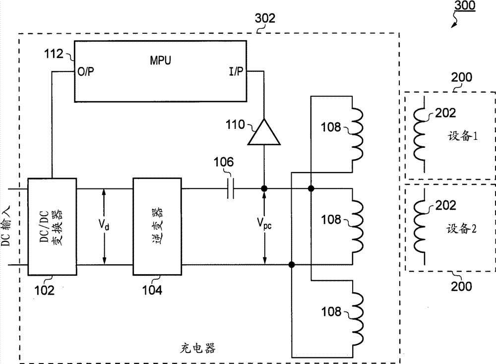
图2是根据本发明的一个实施例的系统300的示意图。系统300包括初级单元302和多个次级单元200。系统300因此可以用于向两个或更多次级单元200感应地同时提供功率(或逐个地提供功率,例如不必将一个设备与另一个设备交换)。
FIG. 2 is a schematic diagram of a
应当理解,图2是在电路电平下呈现的,并且在本发明的该相关实施例中聚焦在电路特征上。然而,如与电路相关一样,本发明扩展到初级单元本身(该初级单元可以包括超出所示的电路特征的特征,例如其物理结构)并扩展到包含这种初级单元的整个功率传输系统。 It should be understood that Figure 2 is presented at a circuit level, and focuses on circuit features in this related embodiment of the invention. However, as related to circuits, the invention extends to the primary unit itself (which may include features beyond those of the circuit shown, such as its physical structure) and to the entire power transmission system comprising such a primary unit.
在图2中,次级单元200被显示为每个次级单元都包括次级线圈202,但是被显示为表示对应的电路设备。这说明次级单元200可以是这种次级设备的仅有的组件,并且也使得该示意图简化。因此,在本发明的一个实施例中,次级单元200可以与图1中的次级单元相同。在本发明的另一个实施例中,图2中的(和其他图中的)次级单元200可以不同于图1中的次级单元,并且可以彼此不同。
In FIG. 2 , the
初级单元302不同于图1中的初级单元100,这是因为它包括多个初级线圈108。初级线圈108并联地连接在一起。尽管图2中示出了三个这样的初级线圈,但是应当理解可以提供两个或更多这样的线圈并且线圈的数目可以较大,例如高达10或高达50或更大。
在图2的实施例中,初级线圈108中的两个被示出为在其附近具有次级单元200,并且第三初级线圈108被显示为在其附近没有次级单元200。这仅仅作为示例,并且应当理解任何数目的初级线圈108(或没有一个初级线圈)在其附近可以具有一个或多个次级单元200,这依赖于初级线圈108的配置和需要功率的次级单元200的数目。初级单元(依赖于其配置)可以同时将功率传输到一个以上的次级单元。相似地,次级单元可以同时从相同初级单元中的一个以上的初级线圈接收功率。
In the embodiment of FIG. 2 , two of the
图2的实施例至少由于下面的理由而是有利的。与图1的示例性系统相比,初级单元302提供有经由多个初级线圈108传输功率的能力,而无需在电路中进行大的复制。特别地,在初级单元302中额外的能力(与图1的系统相比)是通过添加额外的并联的初级线圈108而提供的。以此方式,会导致最小的附加成本和复杂性。
The embodiment of Figure 2 is advantageous for at least the following reasons. In contrast to the exemplary system of FIG. 1 ,
一般地,向所述额外能力提供电路中的低复制的实施例可以比其中复制更低额定(lower-rated)部分的实施例需要更高额定(更高功率能力)的组件。一般地,使用更高额定的组件比增加组件数量可以成本更低。 In general, embodiments that provide such additional capacity with low duplication in circuitry may require higher rated (higher power capability) components than embodiments where lower-rated portions are duplicated. Generally, it can be less costly to use higher rated components than to increase the number of components.
而且,每个初级线圈108上的电压可被调节而无需提供附加的电路,因为初级线圈电压Vpc对于所有并联连接的初级线圈108而言是相同的。因此,并联组合两端的峰值电压被感测并且经由微处理器单元112而被反馈回,并且因此控制系统被布置为使得它将所有初级线圈108保持在相同的调节的电压电平。图2的系统被配置为当在所有初级线圈108附近或仅仅在一些初级线圈108附近存在负载(次级单元/设备)时运行。图2的系统能够在不同初级线圈108上存在不同负载时运行。基于在单个点处对初级线圈电压Vpc-的感测的调节是令人满意的,因为初级线圈108相互并联。串联电容器106被公共地提供到所有初级线圈108。因此,初级线圈108被配置为在预期的频率处谐振(即被调谐的)。预期的频率可以是这样的频率:在该频率处逆变器104生成其交流电(即在交流电的基频处)。
Furthermore, the voltage across each
图3是根据本发明的一个实施例的初级单元306的示意图。初级单元306可以例如与图2实施例中的初级单元302可交换地使用。
FIG. 3 is a schematic diagram of a
初级单元306不同于初级单元302,因为提供了镇流器电路308。此外,从图3更清楚地显示,可以彼此并联地提供任何数目的初级线圈108。
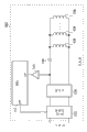
镇流器电路308被提供在逆变器104与电容器106和线圈108的组合之间。镇流器电路308包括电感器310和电容器312。因此,镇流器电路308可被称为LC镇流器电路。电感器308串联连接在逆变器104与电容器106之间。电容器312与电容器106和线圈108的组合并联连接。
A
在本发明中,镇流器电路308是有利的,因为它充当低通滤波器并减少初级线圈108上的信号中存在的谐波的幅值。这可能有助于减少或避免初级单元306生成不想要的射频干扰和电磁干扰。
初级单元306中的镇流器电路308的存在从初级单元的运行稳定的观点来看和在调节初级单元的运行方面也可以是有利的。当初级单元具有单个初级线圈108和当初级单元具有多个初级线圈时,这都是真实的。这种镇流器电路可被有利地配置为通过对组件值的适当选择提高系统的稳定性。现在将进一步考虑与镇流器电路308相关的优点。
The presence of the
图4呈现一组示意图,其对理解感应功率传输系统的初级单元中的镇流器电路的益处有用。 Figure 4 presents a set of schematic diagrams useful for understanding the benefits of a ballast circuit in a primary unit of an inductive power transfer system.
图4A是表示图2的系统的一部分的示意图。假设初级侧被提供有固定的交流电,使得初级线圈108生成电磁场以将功率感应地传输到次级侧。还假设次级侧的特性是未知的,例如次级单元中的负载、存在的次级单元的数目等等。还假设没有提供对初级线圈108中的信号的调节。重要的是,在图4A的电路中不存在镇流器电路。
FIG. 4A is a schematic diagram representing a portion of the system of FIG. 2 . It is assumed that the primary side is supplied with a fixed alternating current such that the
图4B是图4A的初级侧中电路的频率响应的示意性表示。实曲线表明图4A的电路可以具有含有单个主峰值的谐振响应。用虚线示出的曲线将表示其中谐振响应可以随着次级侧变化(例如改变负载、次级单元的数目等等)而变化的方式。如图所示,曲线的斜率可以在谐振峰值任一侧改变或者峰值频率可以改变,或事实上这些改变的组合可能出现。 Figure 4B is a schematic representation of the frequency response of the circuit in the primary side of Figure 4A. The solid curve shows that the circuit of Figure 4A can have a resonant response with a single dominant peak. The curves shown with dashed lines will represent the way in which the resonant response can vary with secondary side changes (eg changing load, number of secondary units, etc.). As shown, the slope of the curve may change on either side of the resonant peak or the peak frequency may change, or indeed a combination of these changes may occur.
应当理解,如果初级侧中的信号在特定频率下(例如由图4B中垂直虚线所示),则变化的频率响应在初级侧中增加了显著的负担(burden),如果期望调节例如初级线圈上的电压的话。该问题在图4A中的单个初级线圈108中存在,并且在图2中的多个相互并联的初级线圈108中恶化。
It should be appreciated that if the signal in the primary side is at a particular frequency (such as shown by the vertical dashed line in Figure 4B), the varying frequency response adds a significant burden in the primary side if it is desired to regulate, e.g. voltage. This problem exists in the single
图4C是表示图3的系统的一部分的示意图。再次假设初级侧被提供有固定的交流电,使得初级线圈108生成电磁场以将功率感应地传输到次级侧。还假设次级侧的特性是未知的,例如次级单元中的负载、存在的次级单元的数目等等是未知的。还假设没有提供对初级线圈108中的信号的调节。然而,在这种情况下,在电路中存在镇流器电路308。
FIG. 4C is a schematic diagram representing a portion of the system of FIG. 3 . Assume again that the primary side is supplied with a fixed alternating current such that the
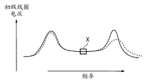
图4D是图4C的初级侧中电路的频率响应的示意性表示。实曲线指示图4C的电路可以被配置为具有含有两个由相对平坦的部分连接的主峰值的谐振响应。用虚线示出的曲线将表示其中谐振响应可以随着次级侧变化(例如改变负载、次级单元的数目等等)而变化的方式。如图所示,尽管峰值的形式可以改变,并且尽管峰值的任一侧上的斜率可以改变,但是基本平坦的中心部分(在图4D中用标记为“X”的方框标记)经受很小的(如果有的话)的变化。 Figure 4D is a schematic representation of the frequency response of the circuit in the primary side of Figure 4C. The solid curve indicates that the circuit of FIG. 4C can be configured to have a resonant response with two main peaks connected by a relatively flat portion. The curves shown with dashed lines will represent the way in which the resonant response can vary with secondary side changes (eg changing load, number of secondary units, etc.). As shown, although the form of the peak can vary, and although the slope on either side of the peak can vary, the substantially flat central portion (marked by the box marked "X" in Fig. 4D) suffers little changes (if any).
因此,如果初级侧中的信号处于被选择为舒适地(comfortably)在方框X内(即在相对稳定的中心部分中)的特定基频,随后随着次级侧的改变而改变的频率响应在初级侧中增加了很少的负担或基本不增加负担,如果期望调节例如初级线圈上的电压的话。有效地,初级侧对次级侧上的变化不敏感(desensitized)。在图4A的电路上,该益处被提供在存在的单个初级线圈108上,并且如果存在多个初级线圈,可能更是如此。因此,图3的电路被认为体现了本发明,即使仅仅提供一个初级线圈108时也是如此。
Thus, if the signal in the primary side is at a particular fundamental frequency chosen to be comfortably within box X (i.e. in the relatively stable central part), then the frequency response that changes as the secondary side changes Little or substantially no load is added in the primary side, if it is desired to regulate, for example, the voltage on the primary coil. Effectively, the primary side is desensitized to changes on the secondary side. On the circuit of Figure 4A, this benefit is provided over the presence of a single
图5是类似于图4C的(即其中初级侧具有镇流器电路的、根据本发明的一个实施例的系统的)示意图。该示意图已经用于仿真系统的运行,以说明镇流器电路的益处。 FIG. 5 is a schematic diagram similar to FIG. 4C , ie of a system according to one embodiment of the invention where the primary side has a ballast circuit. This schematic has been used to simulate the operation of the system to illustrate the benefits of the ballast circuit.
为了容易地理解图5中的电路,用与图1-4中对应元件相同的参考标记来表示相关元件。简言之,初级侧电路被逆变器104驱动并且包括电感器310(镇流器,Lbal)和电容器312(槽路(tank),Ctank),它们的值被选择成使得其被调谐到频率f0=1/(2π√LC)。该电路进一步包括初级线圈108(焊盘(pad)电感器,Lpad或Lp)和电容器106(串联谐振盖(cap),Cp),它们也可被调谐到f-0。频率f0被选择为针对本仿真的逆变器104的开关频率,该频率典型地针对无线功率传输应用处于100-500kHz内。为了与图3的实施例一致,初级芯(core)108(焊盘电感器(pad inductor),Lpad)可以是单个初级线圈108或多个相互并联的(或甚至串联连接)的线圈。图5中的附加标签是用于所述仿真的指示符。
For ease of understanding of the circuit in Fig. 5, relevant elements are denoted by the same reference numerals as corresponding elements in Figs. 1-4. Briefly, the primary side circuit is driven by the
对于所述仿真,电感器310(镇流器)和电容器312(槽路)由恒定的AC电压(从逆变器104提供的)驱动并且可以有效地充当恒定的电流源或被用于提供恒定的线圈电压。这有效地独立于小的组件公差,因为(如上所述的)操作(operation)是在频率响应曲线的两个主谐振峰值之间的平坦区域中执行的。 For the simulations, inductor 310 (ballast) and capacitor 312 (tank) are driven by a constant AC voltage (supplied from inverter 104) and can effectively act as a constant current source or be used to provide a constant the coil voltage. This is effectively independent of small component tolerances because (as described above) operations are performed in the flat region between the two main resonant peaks of the frequency response curve.
图6是基于图5的电路的仿真结果的图。特别地,图6是使用其下面展示的参数值获得的频率响应曲线。这些参数的标记对应于图5中的标记。工作频率被选择为323kHz(0.323MHz)。 FIG. 6 is a graph of simulation results based on the circuit of FIG. 5 . In particular, Figure 6 is the frequency response curve obtained using the parameter values presented below. The notations of these parameters correspond to those in Fig. 5 . The operating frequency is chosen to be 323kHz (0.323MHz).
如从图6所示的实线的曲线可以看出,该频率响应被发现与图4D中所示的几乎一样(much as),即具有两个主谐振峰值,峰值间具有基本平坦的部分。工作频率323kHz被选择在两个主峰值之间的曲线的中心,在该处该曲线是基本平坦的。实线的曲线示出在不存在次级单元时的响应,而虚线曲线示出在存在次级侧并且以全功率工作时的响应。可以看出,曲线中的工作点(在平坦部分中)在这两种情形之间不会显著改变。 As can be seen from the solid line curve shown in FIG. 6, the frequency response was found to be much as shown in FIG. 4D, ie having two main resonant peaks with a substantially flat portion between the peaks. The operating frequency of 323kHz is chosen to be in the center of the curve between the two main peaks, where the curve is substantially flat. The solid line curve shows the response when no secondary unit is present, while the dashed line curve shows the response when the secondary side is present and operating at full power. It can be seen that the operating point in the curve (in the flat part) does not change significantly between the two cases.
在本发明的一个实施例中,有利的是,使得每对组件—即作为一对的电感器310和电容器312和作为另一对的电容器106和初级线圈108—保持被调谐到相同的频率f0(通过适当选择它们的电感和电容值),因为这保持了相同的基本谐振曲线形状。在该约束内,增加镇流器电感器308的电感与初级芯108的电感的比率(“电感器比率”)(即,Lbal/Lpad)使得频率中的谐振峰值进一步分移开,并且降低镇流器电感器308的电感增加了初级线圈中的电流(焊盘电流)。下面的公式对于理解这些关系是有用的。
In one embodiment of the invention, it is advantageous to keep each pair of components—that is, the
谐振峰值被如下定位: The resonance peak is located as follows:
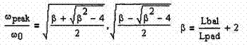
其中ωpeak是峰值角频率(以弧度为单位),ω0是工作角频率(以弧度为单位),即响应曲线的中心频率,Lbal是镇流器电感器310的电感,而Lpad是初级线圈108的电感。
where ωpeak is the peak angular frequency in radians, ω0 is the operating angular frequency in radians, which is the center frequency of the response curve, Lbal is the inductance of the
初级线圈108中的电流由下式近似地给出:
The current in the
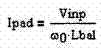
其中Vinp是如图5所示的输入交流电压的峰值幅值。 Where V inp is the peak amplitude of the input AC voltage shown in Figure 5 .
初级线圈上的峰值电压由下式近似地给出: The peak voltage across the primary coil is approximately given by:
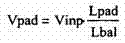
Vinp是由逆变器104生成的基频(在f0处的正弦分量)的幅值。这可被认为等于逆变器干线(rail)电压乘以2/π。
V inp is the magnitude of the fundamental frequency (sinusoidal component at f 0 ) generated by the
图7是示出电感器比率对谐振峰值之间的分隔的影响的仿真结果的图。y轴表示以频率为单位的峰值之间的分隔除以中心频率。中心频率在图6中x轴的中心。图8是示出镇流器电感器310的电感值对初级线圈108中的电流(初级电流)的影响的仿真结果的图。
FIG. 7 is a graph showing simulation results of the effect of inductor ratio on the separation between resonance peaks. The y-axis represents the separation between peaks in frequency divided by the center frequency. The center frequency is at the center of the x-axis in Figure 6. FIG. 8 is a graph showing simulation results of the effect of the inductance value of the
基于上文,在本发明的一个实施例中,用于设计如图5中的电路的示例性设计过程可以如下: Based on the above, in one embodiment of the present invention, an exemplary design process for designing a circuit as shown in FIG. 5 may be as follows:
步骤1:选择镇流器电感器310的电感值Lbal和槽路电容312的电容值Ctank,使得这一对被调谐到频率f0=1/(2π√LC)。还有,选择初级线圈108的电感值Lpad和串联谐振电容器106的电容值Cp,使得这一对被调谐到频率f0。随后,选择频率f0作为逆变器104的开关频率。
Step 1: Select the inductance L bal of the
步骤2:选择电感器比率Lbal/Lpad的值,使得谐振峰值足够远离从而组件公差的影响基本上很小。已经发现Lbal/Lpad=1/4近似地为合理的起点。 Step 2: Choose a value for the inductor ratio L bal /L pad such that the resonant peak is far enough away that the effect of component tolerances is essentially insignificant. L bal /L pad = 1/4 has been found to be approximately a reasonable starting point.
步骤3:因此(一个或多个)初级线圈108上的预期电压近似为: Step 3: The expected voltage across the primary coil(s) 108 is thus approximately:
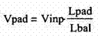
初级线圈中的匝数可被选择以与实际逆变器电压、初级线圈电压和初级线圈电流一起合作。逆变器和线圈电压的选择典型地受到可用的FET、效率要求、成本和EMC(电磁相容性)考虑的影响。设计折衷方案可能意味着步骤2中所选的比率被相应地调整。
The number of turns in the primary coil can be selected to work with the actual inverter voltage, primary coil voltage and primary coil current. The choice of inverter and coil voltage is typically influenced by available FETs, efficiency requirements, cost and EMC (electromagnetic compatibility) considerations. Design tradeoffs may mean that the ratios chosen in
步骤4:如果合适,执行对整体设计的微调。例如,镇流器电感器310和槽路电容器312对的谐振频率可被轻微调整以允许零电压开关(zero-voltage switching)在所有公差条件下被逆变器FET使用。零电压开关(ZVS)的使用导致低开关噪声且损耗减少。
Step 4: Perform fine-tuning of the overall design, if appropriate. For example, the resonant frequency of the
上述步骤在实践中可能需要一起执行或部分地重复执行。在实际的实现方式中,可能存在对组件值的限制,使得对组件值的选择可能不是完全自由的。 In practice, the above steps may need to be executed together or partially repeated. In an actual implementation, there may be restrictions on component values, so that the choice of component values may not be completely free.
回头看图4-8,可以理解,初级线圈具有自感Lpad或Lp,其是隔离的线圈的电抗(忽略寄生现象,比如绕组间(inter-winding)电容)。然而当该线圈耦合到次级单元中的次级线圈时,有效电感可能出现不同并且可以依赖于次级线圈的电感Ls、两个线圈之间的耦合程度和由次级单元施加的负载的阻抗而被修改。因此,所看到的有效电感可能不同于测量的隔离的电感。所述有效电感可以依赖于耦合的强度而变化并且因此可以依赖于初级和次级线圈的对准程度。它也可以依赖于次级负载并且因此可以随时间变化。该有效电感通常确定系统的谐振频率。因此,如在图4B中,可能的是,工作频率有时、或甚至经常或总是不同于当时的谐振频率,从而使得系统通常稍微“非谐振(off resonance)”运行。图4D中的电路的益处因此可以是:系统有意地在两个谐振峰值之间的频率处运行,即该系统被设计为非谐振运行。因此,系统可被认为有些对所看到的有效电感中的变化免疫(immune)或不敏感(即基本稳定的)。 Referring back to Figures 4-8, it can be appreciated that the primary coil has a self-inductance L pad or L p , which is the reactance of the isolated coil (neglecting parasitics such as inter-winding capacitance). However when this coil is coupled to a secondary coil in a secondary unit, the effective inductance may appear different and may depend on the inductance L s of the secondary coil, the degree of coupling between the two coils and the load applied by the secondary unit. impedance is modified. Therefore, the effective inductance seen may differ from the measured isolated inductance. The effective inductance may vary depending on the strength of the coupling and thus may depend on the degree of alignment of the primary and secondary coils. It may also depend on the secondary load and thus may vary over time. This effective inductance generally determines the resonant frequency of the system. Thus, as in Fig. 4B, it is possible that the operating frequency sometimes, or even often or always, differs from the then resonant frequency, so that the system generally operates somewhat "off resonance". A benefit of the circuit in Figure 4D may thus be that the system is intentionally operated at frequencies between the two resonance peaks, ie the system is designed to operate non-resonant. Thus, the system may be considered somewhat immune or insensitive (ie substantially stable) to changes in the observed effective inductance.
图9是根据本发明的一个实施例的系统350的示意图。与系统300类似,系统350包括初级单元352和多个次级单元200。
FIG. 9 is a schematic diagram of a
初级单元352通常与初级单元306相同,除了仅仅显示两个次级线圈108之外,并除了显示初级线圈108的特定示例性实现方式之外。初级单元352中的每个初级线圈108包括充当初级芯109的棒状铁氧体块,其中相应的初级线圈108的线匝缠绕该初级芯并且沿着其长度分布。系统350的次级单元200中的次级线圈302也具有相似的配置。即,图9的每一个次级单元200中的次级线圈202包括充当次级芯203的棒状铁氧体块,其中相应的次级线圈202的线匝缠绕该次级芯并且沿着其长度分布。
在该实施例中,次级线圈202(和芯203)具有比初级线圈108(和芯109)稍小的尺寸,从而在设备定位方面给出了一些放置自由。在本发明的另一个实施例中,初级线圈108可以具有与次级线圈相同的尺寸(或比其稍小的尺寸)。
In this embodiment, the secondary coil 202 (and core 203 ) has slightly smaller dimensions than the primary coil 108 (and core 109 ), giving some freedom of placement in terms of device positioning. In another embodiment of the invention, the
在该实施例中,初级线圈108物理上被设置为使得它们共享公共的线圈轴,然而他们被设置为使得相邻的这些初级线圈具有彼此相反的极性。这在图9中通过以下被例证:彼此相邻的两个示出的初级线圈108的线圈端部被公共地连接在一起并且类似地相隔最远的端部被公共地连接在一起。该布局的优点在于,由初级线圈108生成的远场电磁场在某种程度上可被取消,这可以减少由初级单元352产生的干扰。在该方式中,大量的初级线圈108可以被设置为行,具有交替的极性。在本发明的另一个实施例中,初级线圈108可以以不同的方式布置,例如并排布置。在其他实施例中,初级线圈都可以具有相同的极性,或可以从单独的异相的驱动系统提供相反的极性。
In this embodiment, the
本实施例的初级线圈108的布置适用于上述初级单元的支架格式。该初级线圈108的行可以坐落在该支架下方,从而将支架本身作为功率传输表面。随后,次级单元200可以被布置在支架上以从支架感应地接收功率。
The arrangement of the
图10是根据本发明的一个实施例的初级单元362的示意图。如前所述,本文提出的初级单元中提供的初级线圈108的数目可以随着实施例而变化。据此,初级单元362可以例如与初级单元302、306和352可交换地使用。
Figure 10 is a schematic diagram of a
初级单元362不同于初级单元306的地方如下。首先,包含镇流器电路308、电容器106和初级线圈108之一的电路部分按每个初级线圈108而被重复,并且这些部分并联连接在一起。其次,缓冲器110(峰值检测器)仅仅连接到初级线圈108之一。
因此,在初级单元362中,镇流器电路全都连接到逆变器104,使得逆变器104能够同时驱动它们所有。初级单元362的该配置利用了上面详细讨论的镇流器电路308的益处。即,逆变器104被配置为使得其基本输出频率在每个并联连接的部分的频率响应曲线的基本平坦部分中。通过配置并联连接的部分使得它们彼此相似,它可被布置为使得每个并联连接的部分的频率响应曲线的基本平坦部分在频率上近似地处在相同的位置。因此,并联连接的部分的整个组合(和单独地每个这样的部分)对次级侧的变化(例如对次级单元200的存在/不存在,或次级单元200的类型)不敏感。这是为什么可以调节每个初级单元108上的电压而同时仅仅感测这些线圈108之一(在该情况下为最高线圈108)的电压的一个原因。即,通过调节初级线圈108中的一个的运行,所有初级线圈108的运行都被调节。在成本和复杂性方面有利的是,不需要每个初级线圈108的单独调节的电路(例如需要每个线圈108的单独缓冲器和更复杂的MPU112)。
Thus, in the
图11是根据本发明的一个实施例的初级单元372的示意图。初级单元372可以例如与初级单元302、306、352和362可交换地使用。
FIG. 11 is a schematic diagram of a
初级单元372一般与初级单元362相同,除了每个初级线圈108被提供有经由缓冲器10(峰值检测器)的反馈路径。而且具有多个输入端的MPU374被提供以取代MPU112。
初级单元372在操作中感测每个初级线圈108上的电压并且调节该初级线圈的运行,在这种情况下通过依赖于任何一个或多个那些感测的电压而控制DC/DC转换器102的运行来实现。在某些情况下,例如当仅仅存在一个次级单元200时,可能有利的是基于来自特定初级线圈108的感测的电压控制调节,以用于精确控制该特定线圈。在其他情况下,可能有利的是使调节基于在不同时间不同线圈108上的电压。总的来说,在初级单元372中提供了高的控制能力。
图12-15分别呈现了初级单元382、392、402和412的示意图,每个示意图构成本发明的不同实施例。这些初级单元中的每一个可以例如与初级单元302、306、352、362和372中任一个可交换地使用。
12-15 present schematic diagrams of
初级单元382、392、402和412中的每一个一般地与初级单元302相同,除了下面的差异之外。应当理解这些实施例意欲说明反馈信号(感测电路的运行)可以在初级单元电路中若干不同点中任一个处获得。
Each of
在图12的初级单元382中,如在初级单元302中一样,但从电容器106与逆变器104之间提供AC电压感测。在图13的初级单元392中AC电流传感器394被提供在初级线圈(表示为电流互感器)处。在图14的初级单元402中,DC电压感测被提供在DC/DC转换器102与逆变器104之间。在图15的初级单元412中,DC电流感测(由串联电阻器414和运算放大器416形成)被提供在DC/DC转换器102与逆变器104之间。
In
图16是根据本发明的一个实施例的初级单元422的示意图。初级单元422可以例如与初级单元302、306、352、362、372、382、392、402和412中任一个可交换地使用。
Figure 16 is a schematic diagram of a
初级单元422一般相似于初级单元372,不同之处在于,并联部分没有镇流器电路(但另一个实施例可以包括这种镇流器电路),并且每个并联部分中的电容器106用可变电抗(可变电容器)424取代。而且,初级单元422具有MPU426(取代MPU112),MPU426具有每个电压感测的输入(经由缓冲器110)并具有每个可变电抗424的输出,从而使得控制这些电抗的值。
因此,在初级单元422中,每个并联部分具有串联连接在一起的初级线圈108和可变电抗424。每个可变电抗424在该实施例中被实现为可变电容器,由在MPU426的控制下可被接入或断开的电容器阵列形成。通过示例,可变电容器可以使用MOSFET或MEM来制造。可变电容器的值由MPU426控制。
Thus, in the
当可变电抗424中的电容值改变时,(初级线圈108和可变电抗424的)LC组合被调谐成使得该组合被带入谐振或失去谐振。以此方式,所关注的峰值线圈电压可以基于将LC组合的谐振频率朝向或远离逆变器104的基频调谐而被可控地改变。
When the capacitive value in
因此,在初级单元422中,每个初级线圈108的峰值电压被感测,并且这些反馈信号可被MPU426用来控制DC/DC转换器102和可变电抗424。每个初级线圈108可以调节为处在不同的电压电平。应当理解,尽管本文公开的实施例聚焦于电压感测和调节,本发明的其他实施例可以调节初级线圈108中的电流或功率。
Thus, in
在初级单元422中,对于每个初级线圈108而言,不是必需具有可变电抗424。例如,初级线圈108中的一个可以具有固定的电容器,比如电容器106,而其他初级线圈可以具有可变电抗。可以通过控制DC/DC转换器102来一起调节初级线圈108,并且可以通过控制可变电抗424来相对于彼此(和相对于具有固定电容器106的线圈108)调节初级单元108。更一般地,可以使用可变阻抗(结合了电阻),然而在一些实施例中,与该电阻相关联的损耗(表示为热耗散)可能是不期望的。
In the
图17是根据本发明的一个实施例的初级单元432的示意图。如前所述,初级单元432可以与先前描述的体现本发明的初级单元可交换地使用。
Figure 17 is a schematic diagram of a
初级单元432与初级单元422相同,除了以下不同:取代被公共逆变器104驱动的并联部分,每个这样的部分被半桥434驱动,其中半桥434被公共的驱动器436和振荡器438驱动。
The
专注于初级单元422和432中的LC组合,应当理解,存在若干种形成可变电容器的方法(例如使用变容二极管或各种串联和并联的电容器组合)。可替代地,可以使用与可变电感串联的固定电容器,因为改变L或C将改变整个LC组合。这可以利用各个导体的开关阵列来实现,或例如通过提供缠绕铁氧体棒的线圈,线圈中带有分接头(tap),从而使得不同线匝组可以减短或被选择以改变整个电感。
Focusing on the LC combination in the
图18是根据本发明的一个实施例的初级单元442的示意图。如前所述,初级单元442可以与先前描述的体现本发明的初级单元可交换地使用。 Figure 18 is a schematic diagram of a primary unit 442 according to one embodiment of the present invention. As previously stated, primary unit 442 may be used interchangeably with previously described primary units embodying the present invention.
初级单元442非常相似于初级单元432,除了以下不同:每个并联部分提供有其自己的逆变器104来取代半桥434(以及驱动器436和振荡器438)。而且用固定电容器106替代了每个可变电抗424。
The primary unit 442 is very similar to the
为了提供对每个并联部分的可控性。类似于图17,每个逆变器提供有其自己的可由MPU426控制的可调谐振荡器444。因此,提供给每个初级线圈108的驱动频率(即所关注的逆变器104的基本输出频率)可以被调整以使得它朝向或远离谐振,由此调整其上的AC电压(峰值电压或例如RMS电压)。如在图17中一样,每个初级线圈上的信号经由缓冲器(峰值检测器)110而被感测。并且MPU426在操作中动态控制其输出端上的信号以执行系统控制/调节。因此,MPU426可以选择性地控制DC/DC转换器102的运行和/或一个或多个可调谐振荡器444的运行。MPU426在操作中动态调节每个初级线圈108中的电压(或在其他实施例中,调节电流或功率),从而按照需要使所有的线圈的电压达到相同的电平或不同的电平。
To provide controllability of each parallel section. Similar to FIG. 17 , each inverter is provided with its own tunable oscillator 444 controllable by the
如前所述,对每个逆变器104而言,不是必需提供有其自己的可调谐振荡器444。例如,逆变器104中的一个可以提供有固定频率的振荡器,而其他逆变器可以具有可调谐的振荡器444。可以通过控制DC/DC转换器102调节初级线圈108,并且可以通过控制可调谐振荡器444来相对于彼此(和相对于具有固定频率振荡器的线圈108)调节初级线圈108。
As previously mentioned, it is not necessary for each
图19和20是根据本发明的一些实施例的初级单元的充电表面上可能的初级线圈108布局的示意图。在这些实施例中,预期次级单元200可以放置在要被充电的初级单元的这样的充电表面上的任何地方或基本上任何地方。在这种情况下,所关注的初级单元可以包括多个初级线圈。
19 and 20 are schematic illustrations of possible
在图19中充电表面具有缠绕铁氧体的线圈450的阵列,即铁氧体背板452上缠绕的线圈450的阵列。在图20中,充电表面具有蚀刻到PCB(印刷电路板)462上的印刷的六边形螺旋形线圈460的阵列,其下面可以具有铁氧体和/或具有金属屏蔽。在图20中,每个六边形布置460可以被认为是单独的线圈。矩形464表示放置在所关注的将被充电(即从中感应地接收功率)的初级单元的充电表面上的次级单元200或结合了该次级单元的次级设备的可能印迹(footprint)。
In FIG. 19 the charging surface has an array of ferrite wound coils 450 , ie an array of
应当理解,在一些实施例中,次级单元200的印迹可以小于充电表面上的充电区域,使得可以同时对多个次级单元进行充电。在如图19和20所示的那些阵列中,可以将初级线圈108接入和断开,使得在特定时间只有某些线圈是活动的(active)。当一个初级线圈108被断开时,可以期望改为接入电感器(虚设线圈),以保留相同的整体电感并保持系统谐振。该思想同样可以应用于任何前述实施例以形成本发明的新实施例,并且本文稍后将更详细地探究该思想。即使仅仅单个次级单元接收功率,该概念也可能是有利的,因为不同的初级单元乃至不同数目的初级线圈可能需要依赖于次级单元相对于充电表面的位置和/或取向是活动的。因此,依赖于这种位置/取向,在不同时间可能需要不同的虚设线圈或不同数目的虚设线圈是活动的以保持系统谐振。
It should be understood that in some embodiments, the footprint of the
“虚设线圈”可以是标准的电感器,其可以比初级线圈更小且更轻。而且,它们可被屏蔽或设计以避免辐射,使得不影响由初级线圈生成的电磁场。虚设线圈可以位于远离功率传输区的初级单元中,使得最小化来自它们的任何影响(热、辐射或其他)。因此,可以使用虚设线圈保持从驱动电路看到的电感,而无需影响所生成的电磁场的那些虚设线圈。 The "dummy coil" can be a standard inductor, which can be smaller and lighter than the primary coil. Furthermore, they can be shielded or designed to avoid radiation so as not to affect the electromagnetic field generated by the primary coil. The dummy coils may be located in the primary unit away from the power transfer area, such that any influence (thermal, radiative or otherwise) from them is minimized. Thus, the inductance seen from the driver circuit can be maintained using dummy coils without those dummy coils affecting the generated electromagnetic field.
图21是根据本发明的一个实施例的初级单元472的示意图。如前所述,初级单元472可以与先前描述的体现本发明的任何一个初级单元可交换地使用。 Figure 21 is a schematic diagram of a primary unit 472 according to one embodiment of the present invention. As previously stated, primary unit 472 may be used interchangeably with any of the previously described primary units embodying the invention.
如前实施例,“虚设线圈”的思想可以应用于先前描述的任何实施例,并且初级单元472是应用于图3的初级单元306的该思想的一个示例。
As with the previous embodiments, the idea of a "dummy coil" can be applied to any of the previously described embodiments, and primary unit 472 is an example of this idea applied to
从图21可以看出,每个初级线圈108与开关474串联设置,使得它可以被接入或断开(例如在MPU112的控制下)。与初级线圈108(和开关474)并联地,提供与开关478串联连接的对应的电感器476(充当虚设线圈)。因此,当一个初级线圈108断开时,电感器(虚设线圈)476可以被接入,以便保持初级线圈108和电感器476的并联布置整体电感相同。
As can be seen from FIG. 21 , each
上述解释假设初级线圈108与电感器(虚设线圈)476的电感之间1:1的关系,使得在电路中一种可以连接进来以取代另一种。在考虑初级单元472时,进一步假设是提供相同数目的初级线圈108和电感器(虚设线圈)476。尽管这对于本发明的一个实施例而言是真实的,但是对于其他实施例而言不是真实的。例如,在本发明的一个实施例中,可能已知在任何一个时间,将仅仅断开达到特定数目的初级线圈108。在该情况下,可能的是仅仅提供所述特定数目的电感器476(其数目可以小于初级线圈108的数目)。还有,例如,在本发明的另一个实施例中,可能已知当初级线圈108断开时将总是存在至少特定数目的初级线圈被断开。在该情况下,可能的是配置电感器(虚设线圈)476中的一个,使得它具有与该特定数目的初级线圈108(该数目可以大于1)相同的电感。应当理解,初级线圈108和电感器(虚设线圈)476的其它布置是可能的,从而形成本发明的其他实施例。
The above explanation assumes a 1:1 relationship between the
图22是表现本发明的多个实施例的初级单元492的示意图。
Figure 22 is a schematic diagram of a
初级单元482意图一般地说明接入和断开初级线圈108和电感器(虚设线圈)476的思想可以如何应用于本发明的实施例。初级单元482包括初级线圈108和电感器476的阵列、驱动器484和开关单元486。初级线圈108和电感器476在一端处经由开关单元486公共地连接到驱动器484中的接地端。每个初级线圈108和电感器476的另一端选择性地在开关单元486的控制下可连接到驱动器484的输出端1或输出端2。如将清楚的是,驱动器484可以具有任意数目的输出端,为了方便起见仅仅示出了两个。
初级单元484的配置一般适用于本文所公开的初级单元的实施例。例如,初级线圈108可以是图19或20中的阵列。还有例如,考虑仅仅具有一个输出端(或其他输出端未被连接)的驱动器484,初级线圈108和电感器476可以是图21中的那些,开关单元484可以是图21中的开关474和478的组合,并且驱动器484可以是图21中电路的剩余部分,其中该驱动器输出端在图21中的电容器106与缓冲器110之间。
The configuration of the
在驱动器484中提供一个以上的输出端的益处在于,初级线圈108和电感器476可以分组控制,每输出端对应一个组,使得(例如)一组可以被调节在与另一组不同的电压处。如图22中所例证,任何数目的初级线圈108和电感器476可以被连接到任何的驱动器输出端。
A benefit of providing more than one output in
图23是可以与驱动器484互换以形成本发明的实施例的驱动器492的示意图。应当理解,驱动器492与图23的初级单元492相同,除了以下不同:初级线圈108已经被去除从而留下输出端1和2,并且半桥434的剩余的下面的输出端公共地连接在一起以用于与图22的公共接地兼容。因此,应当理解,一组初级线圈108(或电感器476)可以(经由输出端1)被调节在一个电压下,而另一组初级线圈108(或电感器476)可(经由输出端2)被调节在另一个电压下。再次如前所述,调节可以是电压、电流或功率调节。
Figure 23 is a schematic diagram of a
将不同的初级线圈108调节到不同的初级线圈电压可以用于向在相同充电表面上的或者至少从相同初级单元感应地接收功率的不同的负载(例如不同类型的次级单元200或次级设备)提供不同水平的功率。这也可能是有用的,因为初级单元与次级单元之间的耦合可以依赖于次级单元相对于初级单元的位置和/或取向而广泛改变。而且,实际的电容器和电感器中的公差可能导致一个次级单元或设备与下一个的差异。
Adjusting different
耦合的该变化可能导致次级单元/设备必须应付较大的电压输入范围,并且一般地期望限制次级单元/设备必须应付的电压范围,使得它可以包括较低的电压额定的组件,由此减少成本并改进效率。由此,在本发明的一个实施例中,初级和次级单元可被配置为彼此相互通信。例如,本发明的一个实施例中的次级设备可被配置为向初级单元传达表示其需要的功率的信息。作为响应,初级单元可被配置为相应地调节相关的初级线圈。应当认识到,在一些实施例中,这种通信可能仅仅需要是单向通信,例如从次级单元到初级单元,尽管更加鲁棒的通信可以利用双向通信。 This variation in coupling may result in a larger voltage input range that the secondary unit/device has to deal with, and it is generally desirable to limit the voltage range that the secondary unit/device has to deal with so that it can include lower voltage rated components, thereby Reduce costs and improve efficiency. Thus, in one embodiment of the invention, the primary and secondary units may be configured to communicate with each other. For example, the secondary device in one embodiment of the invention may be configured to communicate information to the primary unit indicating the power it needs. In response, the primary unit may be configured to adjust the associated primary coil accordingly. It should be appreciated that in some embodiments such communication may only need to be one-way communication, eg from the secondary unit to the primary unit, although more robust communication could utilize two-way communication.
图24是根据本发明的一个实施例的初级单元502的示意图。初级单元502是初级单元582的示例性实现方式,其中初级单元108和电感器(虚设线圈)476的叠层体(bank)被单独地示出(如图21)并且其中开关单元486的示例性实现方式被明确示出。而且,示出了对开关单元486的控制可以由MPU504来处理,该MPU504可以是本文所公开的本发明的其他实施例中示出的MPU的一部分或与之分离。
Figure 24 is a schematic diagram of a
在本发明的一个实施例中,与图18类似,可能有利的是可控地改变初级单元上的驱动频率。例如如果次级单元不包括DC/DC转换器而改为将反馈信息传达到初级单元,这可能是有用的。例如,在一个实施例中,初级单元可以潜在地在一个频率处为一个次级单元驱动一个或多个初级线圈并且在不同的频率处为不同的次级单元驱动不同的一个或多个初级线圈,这依赖于来自这些次级单元的反馈信号。在至少在这一点上,一些实施例可以获得来自次级侧的反馈信号(以及或作为代替,来自初级侧的反馈信号)。 In one embodiment of the invention, similar to Fig. 18, it may be advantageous to controllably vary the drive frequency on the primary unit. This may be useful eg if the secondary unit does not comprise a DC/DC converter but instead communicates feedback information to the primary unit. For example, in one embodiment, a primary unit could potentially drive one or more primary coils at one frequency for one secondary unit and a different primary coil or coils at a different frequency for a different secondary unit , which depends on the feedback signals from these secondary units. In at least this regard, some embodiments may obtain a feedback signal from the secondary side (and or instead, a feedback signal from the primary side).
应当理解,在所附权利要求的范围内,本发明的其他实施例是可能的。 It will be appreciated that other embodiments of the invention are possible within the scope of the appended claims.
Claims (22)
Applications Claiming Priority (5)
| Application Number | Priority Date | Filing Date | Title |
|---|---|---|---|
| GB0724982.4 | 2007-12-21 | ||
| GB0724981A GB0724981D0 (en) | 2007-12-21 | 2007-12-21 | Enhanced power supply |
| GB0724982A GB0724982D0 (en) | 2007-12-21 | 2007-12-21 | Inductive power supply |
| GB0724981.6 | 2007-12-21 | ||
| CN2008801273121A CN101978571B (en) | 2007-12-21 | 2008-12-18 | Circuits for inductive power transfer |
Related Parent Applications (1)
| Application Number | Title | Priority Date | Filing Date |
|---|---|---|---|
| CN2008801273121A Division CN101978571B (en) | 2007-12-21 | 2008-12-18 | Circuits for inductive power transfer |
Publications (2)
| Publication Number | Publication Date |
|---|---|
| CN103259344A true CN103259344A (en) | 2013-08-21 |
| CN103259344B CN103259344B (en) | 2016-08-10 |
Family
ID=40430486
Family Applications (3)
| Application Number | Title | Priority Date | Filing Date |
|---|---|---|---|
| CN2008801273121A Active CN101978571B (en) | 2007-12-21 | 2008-12-18 | Circuits for inductive power transfer |
| CN2008801272557A Pending CN101981780A (en) | 2007-12-21 | 2008-12-18 | Inductive power transfer |
| CN201310174376.XA Active CN103259344B (en) | 2007-12-21 | 2008-12-18 | Circuit for induced power transmission |
Family Applications Before (2)
| Application Number | Title | Priority Date | Filing Date |
|---|---|---|---|
| CN2008801273121A Active CN101978571B (en) | 2007-12-21 | 2008-12-18 | Circuits for inductive power transfer |
| CN2008801272557A Pending CN101981780A (en) | 2007-12-21 | 2008-12-18 | Inductive power transfer |
Country Status (11)
| Country | Link |
|---|---|
| US (6) | US8884468B2 (en) |
| EP (3) | EP2690739A2 (en) |
| JP (2) | JP2011507481A (en) |
| KR (3) | KR101687126B1 (en) |
| CN (3) | CN101978571B (en) |
| AU (2) | AU2008339681A1 (en) |
| CA (2) | CA2709860A1 (en) |
| MY (1) | MY154347A (en) |
| RU (2) | RU2010129842A (en) |
| TW (3) | TWI508408B (en) |
| WO (2) | WO2009081115A1 (en) |
Cited By (10)
| Publication number | Priority date | Publication date | Assignee | Title |
|---|---|---|---|---|
| CN104810906A (en) * | 2015-03-18 | 2015-07-29 | 天津大学 | Electric automobile wireless charging system based on intelligent coil arrays |
| CN106330141A (en) * | 2016-09-21 | 2017-01-11 | 广东骏丰频谱股份有限公司 | Schumann resonance generating device |
| CN107112813A (en) * | 2014-10-27 | 2017-08-29 | 高通股份有限公司 | Wireless power multi-coil mutual inductance removing method and device |
| CN108390475A (en) * | 2017-01-13 | 2018-08-10 | 三星电机株式会社 | Foreign bodies detection circuit and use its wireless power sending device |
| CN109643913A (en) * | 2016-08-22 | 2019-04-16 | 昕诺飞控股有限公司 | Interface circuit and external circuit |
| CN109849699A (en) * | 2019-03-11 | 2019-06-07 | 武汉楚象能源科技有限公司 | A kind of module type wireless charging system and device |
| US10530425B2 (en) | 2011-09-12 | 2020-01-07 | Sony Corporation | Device and system for power transmission |
| CN114072308A (en) * | 2019-05-03 | 2022-02-18 | 韦特里西提公司 | Active harmonic cancellation |
| CN114530949A (en) * | 2022-01-20 | 2022-05-24 | 荣耀终端有限公司 | Wireless charging transmitting terminal, charging base and system |
| CN115800559A (en) * | 2022-12-02 | 2023-03-14 | 重庆尚翔电气技术有限公司 | A Resonance Compensation Cascaded Transformer Group Energy Harvesting Method |
Families Citing this family (447)
| Publication number | Priority date | Publication date | Assignee | Title |
|---|---|---|---|---|
| WO2005109597A1 (en) | 2004-05-11 | 2005-11-17 | Splashpower Limited | Controlling inductive power transfer systems |
| GB2414120B (en) | 2004-05-11 | 2008-04-02 | Splashpower Ltd | Controlling inductive power transfer systems |
| CA2709860A1 (en) | 2007-12-21 | 2009-07-02 | Access Business Group International Llc | Inductive power transfer |
| JP2009169327A (en) * | 2008-01-21 | 2009-07-30 | Hitachi Displays Ltd | Power transmission circuit |
| US8855554B2 (en) * | 2008-03-05 | 2014-10-07 | Qualcomm Incorporated | Packaging and details of a wireless power device |
| US8981598B2 (en) | 2008-07-02 | 2015-03-17 | Powermat Technologies Ltd. | Energy efficient inductive power transmission system and method |
| US8234509B2 (en) * | 2008-09-26 | 2012-07-31 | Hewlett-Packard Development Company, L.P. | Portable power supply device for mobile computing devices |
| US20110074346A1 (en) * | 2009-09-25 | 2011-03-31 | Hall Katherine L | Vehicle charger safety system and method |
| JP5258521B2 (en) * | 2008-11-14 | 2013-08-07 | トヨタ自動車株式会社 | Power supply system |
| CN102273046A (en) * | 2009-01-08 | 2011-12-07 | Nec东金株式会社 | Electric power transmitting apparatus and noncontact electric power transmission system |
| US8497658B2 (en) | 2009-01-22 | 2013-07-30 | Qualcomm Incorporated | Adaptive power control for wireless charging of devices |
| US9407327B2 (en) * | 2009-02-13 | 2016-08-02 | Qualcomm Incorporated | Wireless power for chargeable and charging devices |
| JP5621203B2 (en) * | 2009-03-30 | 2014-11-12 | 富士通株式会社 | Wireless power supply system and wireless power supply method |
| JP5353376B2 (en) * | 2009-03-31 | 2013-11-27 | 富士通株式会社 | Wireless power device and wireless power receiving method |
| US8536736B2 (en) * | 2009-04-03 | 2013-09-17 | International Business Machines Corporation | Wireless power infrastructure |
| EP2417686A1 (en) | 2009-04-08 | 2012-02-15 | Access Business Group International LLC | Selectable coil array |
| JP5431774B2 (en) * | 2009-04-14 | 2014-03-05 | 富士通テン株式会社 | Wireless power transmission apparatus and wireless power transmission method |
| EP2433347B1 (en) * | 2009-05-20 | 2013-10-23 | Koninklijke Philips N.V. | Electronic device having an inductive receiver coil with ultra-thin shielding layer and method |
| US8655272B2 (en) * | 2009-07-07 | 2014-02-18 | Nokia Corporation | Wireless charging coil filtering |
| DE102009033236A1 (en) * | 2009-07-14 | 2011-01-20 | Conductix-Wampfler Ag | Device for inductive transmission of electrical energy |
| DE102009033239C5 (en) | 2009-07-14 | 2023-05-17 | Conductix-Wampfler Gmbh | Device for the inductive transmission of electrical energy |
| DE102009033237A1 (en) | 2009-07-14 | 2011-01-20 | Conductix-Wampfler Ag | Device for inductive transmission of electrical energy |
| RU2540896C2 (en) | 2009-07-24 | 2015-02-10 | Эксесс Бизнесс Груп Интернешнл Ллс | Power supply |
| CN102013736B (en) * | 2009-09-03 | 2013-10-16 | Tdk株式会社 | Wireless power feeder and wireless power transmission system |
| US8575944B2 (en) | 2009-11-03 | 2013-11-05 | Robert Bosch Gmbh | Foreign object detection in inductive coupled devices |
| WO2011055158A1 (en) * | 2009-11-03 | 2011-05-12 | City University Of Hong Kong | A passive lc ballast and method of manufacturing a passive lc ballast |
| DE102009057437B4 (en) * | 2009-12-09 | 2023-03-16 | Sew-Eurodrive Gmbh & Co Kg | Arrangement for inductive charging of an energy storage vehicle and charging station |
| WO2011091343A2 (en) * | 2010-01-25 | 2011-07-28 | Access Business Group International Llc | Systems and methods for detecting data communication over a wireless power link |
| CN102823101B (en) * | 2010-02-08 | 2015-06-17 | 捷通国际有限公司 | Input parasitic metal detection |
| CN107040291B (en) * | 2010-03-10 | 2021-06-15 | 无线电力公司 | Sources for Wireless Power Transfer Systems |
| US9106086B2 (en) | 2010-03-11 | 2015-08-11 | Qualcomm Incorporated | Detection and protection of devices within a wireless power system |
| DE102010012356B4 (en) | 2010-03-22 | 2021-04-29 | Sew-Eurodrive Gmbh & Co Kg | System for contactless energy transfer to a vehicle |
| JP2011211760A (en) * | 2010-03-26 | 2011-10-20 | Panasonic Electric Works Co Ltd | Contactless power supply device and contactless charging system |
| US9561730B2 (en) * | 2010-04-08 | 2017-02-07 | Qualcomm Incorporated | Wireless power transmission in electric vehicles |
| US10343535B2 (en) | 2010-04-08 | 2019-07-09 | Witricity Corporation | Wireless power antenna alignment adjustment system for vehicles |
| KR101142446B1 (en) * | 2010-05-04 | 2012-05-11 | 국민대학교산학협력단 | wireless power transmission device with a tunable impedance matching circuit |
| JP2011250615A (en) * | 2010-05-28 | 2011-12-08 | Nec Tokin Corp | Non-contact power transmission and communication system |
| US9413197B2 (en) | 2010-05-31 | 2016-08-09 | Fu Da Tong Technology Co., Ltd. | Inductive power supply system and intruding metal detection method thereof |
| TWI473381B (en) * | 2011-09-20 | 2015-02-11 | 富達通科技股份有限公司 | Inductive power supply and metal foreign matter detection method thereof |
| US8841881B2 (en) | 2010-06-02 | 2014-09-23 | Bryan Marc Failing | Energy transfer with vehicles |
| US8890470B2 (en) | 2010-06-11 | 2014-11-18 | Mojo Mobility, Inc. | System for wireless power transfer that supports interoperability, and multi-pole magnets for use therewith |
| JP2012016125A (en) * | 2010-06-30 | 2012-01-19 | Panasonic Electric Works Co Ltd | Non-contact power supply system and metal foreign matter detection device for non-contact power supply system |
| US20130163635A1 (en) | 2010-07-07 | 2013-06-27 | Avinash Karanth | Foreign object detection in inductive coupled wireless power transfer environment using thermal sensors |
| DE102010026780A1 (en) | 2010-07-09 | 2012-01-12 | Audi Ag | Measuring a temperature during contactless transmission of energy |
| JP5736991B2 (en) * | 2010-07-22 | 2015-06-17 | Tdk株式会社 | Wireless power supply apparatus and wireless power transmission system |
| TWI451238B (en) * | 2010-07-28 | 2014-09-01 | Mstar Semiconductor Inc | Power control apparatus and method thereof and mobile apparatus using it |
| US9386731B2 (en) * | 2010-08-10 | 2016-07-05 | Powerbyproxi Limited | Magnetic shield |
| JP2012044735A (en) * | 2010-08-13 | 2012-03-01 | Sony Corp | Wireless charging system |
| JP5664015B2 (en) * | 2010-08-23 | 2015-02-04 | Tdk株式会社 | Coil device and non-contact power transmission device |
| JP2012049434A (en) * | 2010-08-30 | 2012-03-08 | Sony Corp | Electronic component, feeder device, power receiver, and wireless feeder system |
| KR101782354B1 (en) | 2010-08-30 | 2017-09-27 | 삼성전자주식회사 | Apparatus and method for resonant power transmission and resonant power reception |
| NZ588159A (en) * | 2010-09-23 | 2014-01-31 | Powerbyproxi Ltd | A contactless power transfer system |
| US9294153B2 (en) * | 2010-09-23 | 2016-03-22 | Texas Instruments Incorporated | Systems and methods of wireless power transfer with interference detection |
| DE102010043154A1 (en) * | 2010-10-29 | 2012-05-03 | Fraunhofer-Gesellschaft zur Förderung der angewandten Forschung e.V. | Portable electronic device, external base device, method for coupling the portable electronic device to an external base device and use of the external base device for coupling the portable electronic device |
| US9219378B2 (en) * | 2010-11-01 | 2015-12-22 | Qualcomm Incorporated | Wireless charging of devices |
| KR101213086B1 (en) * | 2010-11-04 | 2012-12-18 | 유한회사 한림포스텍 | Method for controlling wireless power signal in wireless power transmission device and wireless power transmission using the same |
| TWI435511B (en) * | 2010-12-06 | 2014-04-21 | Asustek Comp Inc | Wireless charging system and transmission circuit thereof |
| DE102010054472B4 (en) | 2010-12-14 | 2025-12-11 | Enrx Ipt Gmbh | Device for the inductive transmission of electrical energy |
| US20120146424A1 (en) * | 2010-12-14 | 2012-06-14 | Takashi Urano | Wireless power feeder and wireless power transmission system |
| US9058928B2 (en) | 2010-12-14 | 2015-06-16 | Tdk Corporation | Wireless power feeder and wireless power transmission system |
| KR101750415B1 (en) | 2010-12-16 | 2017-06-26 | 삼성전자주식회사 | Protector of rectifier, Wireless power receiving apparatus including the protector |
| US8800738B2 (en) * | 2010-12-28 | 2014-08-12 | Tdk Corporation | Wireless power feeder and wireless power receiver |
| US9088307B2 (en) * | 2010-12-29 | 2015-07-21 | National Semiconductor Corporation | Non-resonant and quasi-resonant system for wireless power transmission to multiple receivers |
| US9831687B2 (en) | 2011-02-01 | 2017-11-28 | Fu Da Tong Technology Co., Ltd. | Supplying-end module for induction-type power supply system and signal analysis circuit therein |
| US9600021B2 (en) | 2011-02-01 | 2017-03-21 | Fu Da Tong Technology Co., Ltd. | Operating clock synchronization adjusting method for induction type power supply system |
| TWI570427B (en) | 2015-10-28 | 2017-02-11 | 富達通科技股份有限公司 | Inductive power supply and metal foreign matter detecting method thereof |
| US10289142B2 (en) | 2011-02-01 | 2019-05-14 | Fu Da Tong Technology Co., Ltd. | Induction type power supply system and intruding metal detection method thereof |
| US10630113B2 (en) | 2011-02-01 | 2020-04-21 | Fu Da Tong Technology Co., Ltd | Power supply device of induction type power supply system and RF magnetic card identification method of the same |
| US10615645B2 (en) | 2011-02-01 | 2020-04-07 | Fu Da Tong Technology Co., Ltd | Power supply device of induction type power supply system and NFC device identification method of the same |
| US10312748B2 (en) | 2011-02-01 | 2019-06-04 | Fu Da Tong Techology Co., Ltd. | Signal analysis method and circuit |
| US9628147B2 (en) | 2011-02-01 | 2017-04-18 | Fu Da Tong Technology Co., Ltd. | Method of automatically adjusting determination voltage and voltage adjusting device thereof |
| US10056944B2 (en) | 2011-02-01 | 2018-08-21 | Fu Da Tong Technology Co., Ltd. | Data determination method for supplying-end module of induction type power supply system and related supplying-end module |
| US10038338B2 (en) | 2011-02-01 | 2018-07-31 | Fu Da Tong Technology Co., Ltd. | Signal modulation method and signal rectification and modulation device |
| US9671444B2 (en) | 2011-02-01 | 2017-06-06 | Fu Da Tong Technology Co., Ltd. | Current signal sensing method for supplying-end module of induction type power supply system |
| TWI568125B (en) | 2015-01-14 | 2017-01-21 | 富達通科技股份有限公司 | Power supply module of inductive power supply and voltage measuring method thereof |
| JP5713714B2 (en) * | 2011-02-10 | 2015-05-07 | キヤノン株式会社 | Power supply apparatus and control method |
| US9118357B2 (en) * | 2011-02-17 | 2015-08-25 | Qualcomm Incorporated | Systems and methods for controlling output power of a wireless power transmitter |
| KR101243587B1 (en) * | 2011-02-17 | 2013-03-20 | 주식회사 팬택 | Non-contract charging device, non-contact charghing system and non-contact charging method |
| JP5751858B2 (en) * | 2011-02-22 | 2015-07-22 | キヤノン株式会社 | Power supply apparatus and control method |
| JP5805408B2 (en) * | 2011-03-10 | 2015-11-04 | 株式会社レゾナント・システムズ | Bus digital wireless microphone system |
| EP2858205A1 (en) | 2011-04-08 | 2015-04-08 | Access Business Group International LLC | Counter wound inductive power supply |
| US9912201B2 (en) * | 2011-04-11 | 2018-03-06 | Texas Instruments Incorporated | Systems and methods of detecting a change in object presence in a magnetic field |
| US9735623B2 (en) | 2011-05-17 | 2017-08-15 | Samsung Electronics Co., Ltd. | Power transmitting method and power transmitter for communication with power receiver |
| KR102017106B1 (en) * | 2011-05-17 | 2019-10-21 | 삼성전자주식회사 | Power transmitting device and method of transmitting power for communicating with one or more power receiving devices |
| DE102011076186A1 (en) * | 2011-05-20 | 2012-11-22 | Siemens Aktiengesellschaft | Arrangement and method for eliminating a disturbance of a wireless energy transmission |
| DE102011050655B4 (en) | 2011-05-26 | 2024-08-22 | Enrx Ipt Gmbh | Method for detecting an electrically conductive foreign body and device for inductive transmission of electrical energy |
| DE202011050264U1 (en) | 2011-05-26 | 2012-08-27 | Conductix-Wampfler Gmbh | Device for inductive transmission of electrical energy |
| JP6067211B2 (en) * | 2011-05-27 | 2017-01-25 | 日産自動車株式会社 | Non-contact power feeding device |
| WO2012170822A2 (en) * | 2011-06-10 | 2012-12-13 | Access Business Group International Llc | System and method for detecting, characterizing, and tracking an inductive power receiver |
| DE102011105063B4 (en) * | 2011-06-21 | 2023-09-21 | Airbus Operations Gmbh | Detection of a foreign body in an inductive transmission path |
| US9300147B2 (en) * | 2011-06-29 | 2016-03-29 | Lg Electronics Inc. | Method for avoiding signal collision in wireless power transfer |
| JP5071574B1 (en) | 2011-07-05 | 2012-11-14 | ソニー株式会社 | Sensing device, power receiving device, non-contact power transmission system, and sensing method |
| JP5899490B2 (en) | 2011-07-20 | 2016-04-06 | パナソニックIpマネジメント株式会社 | Contactless power supply system |
| AU2012289855A1 (en) | 2011-08-04 | 2014-03-13 | Witricity Corporation | Tunable wireless power architectures |
| WO2013022255A2 (en) * | 2011-08-09 | 2013-02-14 | 주식회사 케이더파워 | High efficiency wireless charger |
| TWI425738B (en) * | 2011-08-12 | 2014-02-01 | 富達通科技股份有限公司 | Induction charging method |
| KR101880030B1 (en) | 2011-08-25 | 2018-07-23 | 삼성전자주식회사 | Sauce apparatus and method that control magnetic field using two sauce resonators in Wireless Resonant Power Transfer system |
| US8909149B2 (en) * | 2011-08-26 | 2014-12-09 | Hewlett-Packard Development Company, L.P. | Media module of a device |
| EP2566005A1 (en) * | 2011-09-05 | 2013-03-06 | RRC power solutions GmbH | Switching assembly and method for inductive energy transfer |
| EP2566028B1 (en) * | 2011-09-05 | 2014-07-09 | RRC power solutions GmbH | Switching assembly and method for inductive energy transfer |
| US9252846B2 (en) | 2011-09-09 | 2016-02-02 | Qualcomm Incorporated | Systems and methods for detecting and identifying a wireless power device |
| WO2013036947A2 (en) * | 2011-09-09 | 2013-03-14 | Witricity Corporation | Foreign object detection in wireless energy transfer systems |
| JP5940784B2 (en) * | 2011-09-09 | 2016-06-29 | 国立大学法人埼玉大学 | Non-contact power feeding device for moving objects |
| US20130062966A1 (en) * | 2011-09-12 | 2013-03-14 | Witricity Corporation | Reconfigurable control architectures and algorithms for electric vehicle wireless energy transfer systems |
| JP5842106B2 (en) * | 2011-09-20 | 2016-01-13 | パナソニックIpマネジメント株式会社 | Contactless power supply system |
| US9553485B2 (en) | 2011-10-13 | 2017-01-24 | Integrated Device Technology, Inc. | Apparatus, system, and method for detecting a foreign object in an inductive wireless power transfer system based on input power |
| US9450648B2 (en) * | 2011-10-13 | 2016-09-20 | Integrated Device Technology, Inc. | Apparatus, system, and method for detecting a foreign object in an inductive wireless power transfer system |
| WO2013057896A1 (en) * | 2011-10-18 | 2013-04-25 | 株式会社アドバンテスト | Wireless power receiving apparatus, wireless power supplying apparatus, and wireless power supplying system |
| CA2794161A1 (en) * | 2011-11-03 | 2013-05-03 | Shaw Industries Group, Inc. | Wireless energy transfer systems |
| US9118203B2 (en) | 2011-11-15 | 2015-08-25 | Qualcomm Incorporated | Systems and methods for induction charging with a closed magnetic loop |
| CN103124083A (en) * | 2011-11-18 | 2013-05-29 | 深圳富泰宏精密工业有限公司 | Wireless charging type portable type electronic device and matched charging device |
| JP5842161B2 (en) * | 2011-11-22 | 2016-01-13 | パナソニックIpマネジメント株式会社 | Lighting apparatus and visible light communication system using the same |
| DE102011086904A1 (en) * | 2011-11-23 | 2013-05-23 | Robert Bosch Gmbh | Device and method for inductive energy transmission |
| JP5838768B2 (en) * | 2011-11-30 | 2016-01-06 | ソニー株式会社 | Sensing device, power receiving device, non-contact power transmission system, and sensing method |
| US9041254B2 (en) * | 2011-12-14 | 2015-05-26 | Linear Technology Corporation | Primary unit control of resonant inductive power transfer system for optimum efficiency |
| WO2013088641A1 (en) * | 2011-12-14 | 2013-06-20 | パナソニック株式会社 | Information transmission device and system |
| CN103348562B (en) | 2011-12-14 | 2017-05-10 | 松下知识产权经营株式会社 | Contactless connector system and power transmission system |
| US9806537B2 (en) | 2011-12-15 | 2017-10-31 | Samsung Electronics Co., Ltd | Apparatus and method for determining whether a power receiver is removed from the apparatus |
| DE102011088911A1 (en) * | 2011-12-16 | 2013-06-20 | Robert Bosch Gmbh | Object recognition with wireless energy transmission |
| US12415429B2 (en) * | 2011-12-16 | 2025-09-16 | Auckland Uniservices Limited | Inductive power transfer system and method |
| JP6186373B2 (en) * | 2011-12-22 | 2017-08-23 | ハンリム ポステック カンパニー リミテッド | Wireless power transmission device and wireless power signal transmission control method in wireless power transmission device |
| JP6019581B2 (en) * | 2011-12-26 | 2016-11-02 | ソニー株式会社 | Detection device, detection system, power transmission device, non-contact power transmission system, and detection method |
| US11144630B2 (en) | 2011-12-30 | 2021-10-12 | Bedrock Automation Platforms Inc. | Image capture devices for a secure industrial control system |
| US9600434B1 (en) | 2011-12-30 | 2017-03-21 | Bedrock Automation Platforms, Inc. | Switch fabric having a serial communications interface and a parallel communications interface |
| US8971072B2 (en) * | 2011-12-30 | 2015-03-03 | Bedrock Automation Platforms Inc. | Electromagnetic connector for an industrial control system |
| US9727511B2 (en) | 2011-12-30 | 2017-08-08 | Bedrock Automation Platforms Inc. | Input/output module with multi-channel switching capability |
| US12061685B2 (en) | 2011-12-30 | 2024-08-13 | Analog Devices, Inc. | Image capture devices for a secure industrial control system |
| US8868813B2 (en) | 2011-12-30 | 2014-10-21 | Bedrock Automation Platforms Inc. | Communications control system with a serial communications interface and a parallel communications interface |
| US11967839B2 (en) | 2011-12-30 | 2024-04-23 | Analog Devices, Inc. | Electromagnetic connector for an industrial control system |
| US8862802B2 (en) * | 2011-12-30 | 2014-10-14 | Bedrock Automation Platforms Inc. | Switch fabric having a serial communications interface and a parallel communications interface |
| US9191203B2 (en) | 2013-08-06 | 2015-11-17 | Bedrock Automation Platforms Inc. | Secure industrial control system |
| US10834820B2 (en) | 2013-08-06 | 2020-11-10 | Bedrock Automation Platforms Inc. | Industrial control system cable |
| US11314854B2 (en) | 2011-12-30 | 2022-04-26 | Bedrock Automation Platforms Inc. | Image capture devices for a secure industrial control system |
| US9467297B2 (en) | 2013-08-06 | 2016-10-11 | Bedrock Automation Platforms Inc. | Industrial control system redundant communications/control modules authentication |
| US9437967B2 (en) | 2011-12-30 | 2016-09-06 | Bedrock Automation Platforms, Inc. | Electromagnetic connector for an industrial control system |
| US10834094B2 (en) | 2013-08-06 | 2020-11-10 | Bedrock Automation Platforms Inc. | Operator action authentication in an industrial control system |
| KR102014126B1 (en) * | 2012-01-06 | 2019-08-26 | 필립스 아이피 벤쳐스 비.브이. | Wireless power receiver system |
| US9417199B2 (en) * | 2012-01-17 | 2016-08-16 | Triune Systems, LLC | Method and system of wireless power transfer foreign object detection |
| JP6090172B2 (en) * | 2012-01-17 | 2017-03-08 | パナソニックIpマネジメント株式会社 | Contactless charging method |
| US10778045B2 (en) | 2012-01-30 | 2020-09-15 | Triune Ip, Llc | Method and system of wireless power transfer foreign object detection |
| JP2013158589A (en) | 2012-02-08 | 2013-08-19 | Toshiba Corp | Medical image diagnosis apparatus |
| KR101360744B1 (en) * | 2012-02-17 | 2014-02-10 | 엘지이노텍 주식회사 | Apparatus for transmitting wireless power, apparatus for receiving wireless power, system for transmitting wireless power and method for transmitting wireless power |
| KR101305828B1 (en) * | 2012-03-07 | 2013-09-06 | 엘지이노텍 주식회사 | Apparatus for transmitting wireless power, apparatus for receiving wireless power, system for transmitting wireless power and method for transmitting wireless power |
| TWI587597B (en) | 2012-02-17 | 2017-06-11 | Lg伊諾特股份有限公司 | Wireless power transmitter, wireless power receiver, and power transmission method of wireless power transmitting system |
| DE112012005961A5 (en) * | 2012-02-29 | 2014-12-11 | Siemens Aktiengesellschaft | Charging system for the galvanically isolated charging of an electrical energy storage device of a vehicle, electrically driven vehicle, charging station for a vehicle and corresponding method |
| JP2013183496A (en) * | 2012-02-29 | 2013-09-12 | Equos Research Co Ltd | Power transmission system |
| JP2013183497A (en) | 2012-02-29 | 2013-09-12 | Equos Research Co Ltd | Power transmission system |
| JP5909700B2 (en) | 2012-03-09 | 2016-04-27 | パナソニックIpマネジメント株式会社 | Metal detection method, metal detection device, and metal detection method and non-contact power supply device of non-contact power supply device |
| JP5903624B2 (en) * | 2012-03-09 | 2016-04-13 | パナソニックIpマネジメント株式会社 | Non-contact power transmission device driving method and non-contact power transmission device |
| FR2988241B1 (en) * | 2012-03-13 | 2019-08-09 | Renault S.A.S | WIRELESS COMMUNICATION SYSTEM WITH MULTIPLE MULTIPLEX RECEIVERS. |
| CN104094498B (en) * | 2012-03-14 | 2017-11-21 | 松下知识产权经营株式会社 | Power supply device, power receiving device and power supply system |
| US20130257167A1 (en) * | 2012-03-29 | 2013-10-03 | Integrated Device Technology, Inc. | Apparatuses, systems, and methods for power transfer adjustment in wireless power transfer systems |
| US8942624B2 (en) | 2012-03-30 | 2015-01-27 | Integrated Device Technology, Inc. | Apparatus, system, and method for back-channel communication in an inductive wireless power transfer system |
| CN102607727A (en) * | 2012-04-05 | 2012-07-25 | 杭州凯源电子有限公司 | Radio-frequency temperature measuring device with function of resonance isolation electricity-taking |
| JP5966538B2 (en) * | 2012-04-10 | 2016-08-10 | ソニー株式会社 | Power receiving device, power receiving device control method, and power feeding system |
| KR101890705B1 (en) | 2012-04-19 | 2018-08-22 | 삼성전자주식회사 | Signal process apparatus and signal process method |
| KR101844422B1 (en) | 2012-04-19 | 2018-04-03 | 삼성전자주식회사 | Apparatus and method for wireless energy transmission and apparatus wireless energy reception |
| JP5872374B2 (en) * | 2012-04-25 | 2016-03-01 | 三洋電機株式会社 | Contactless power supply method |
| US9696358B2 (en) | 2012-05-02 | 2017-07-04 | Powerbyproxi Limited | Method for detecting and identifying a receiver in an inductive power transfer system |
| WO2013164831A1 (en) | 2012-05-03 | 2013-11-07 | Powermat Technologies Ltd. | System and method for triggering power transfer across an inductive power coupling and non resonant transmission |
| JP5976385B2 (en) * | 2012-05-07 | 2016-08-23 | ソニー株式会社 | Detecting device, power receiving device, power transmitting device, and non-contact power feeding system |
| US9536656B2 (en) | 2012-05-21 | 2017-01-03 | Texas Instruments Incorporated | Systems and methods of reduction of parasitic losses in a wireless power system |
| JP5915904B2 (en) * | 2012-06-22 | 2016-05-11 | ソニー株式会社 | Processing apparatus, processing method, and program |
| DE202013012730U1 (en) | 2012-06-22 | 2018-12-02 | Sony Corporation | processing device |
| DE102012210897A1 (en) * | 2012-06-26 | 2014-01-02 | Robert Bosch Gmbh | Object recognition for an energy transmission system |
| KR101338690B1 (en) * | 2012-07-06 | 2013-12-09 | 홍익대학교 산학협력단 | Method and apparatus for adaptive impedance matching of wireless power transfer |
| KR101950688B1 (en) | 2012-07-09 | 2019-02-21 | 삼성전자주식회사 | Wireless power transmitter and method for controlling thereof |
| KR102074475B1 (en) | 2012-07-10 | 2020-02-06 | 지이 하이브리드 테크놀로지스, 엘엘씨 | Apparatus and method for detecting foreign object in wireless power transmitting system |
| US20140021912A1 (en) * | 2012-07-19 | 2014-01-23 | Ford Global Technologies, Llc | Vehicle battery charging system and method |
| US10773596B2 (en) | 2012-07-19 | 2020-09-15 | Ford Global Technologies, Llc | Vehicle battery charging system and method |
| US9467002B2 (en) | 2012-07-19 | 2016-10-11 | Ford Global Technologies, Llc | Vehicle charging system |
| KR101413490B1 (en) * | 2012-07-24 | 2014-07-01 | (주)기술과가치 | Wiress Power Transmission Apparatus and Method for Constructing Wiress Charging Space Using the Same |
| WO2014018974A1 (en) | 2012-07-27 | 2014-01-30 | Thoratec Corporation | Magnetic power transmission utilizing phased transmitter coil arrays and phased receiver coil arrays |
| WO2014018972A1 (en) | 2012-07-27 | 2014-01-30 | Thoratec Corporation | Computer modeling for resonant power transfer systems |
| US10525181B2 (en) | 2012-07-27 | 2020-01-07 | Tc1 Llc | Resonant power transfer system and method of estimating system state |
| US9592397B2 (en) | 2012-07-27 | 2017-03-14 | Thoratec Corporation | Thermal management for implantable wireless power transfer systems |
| US9287040B2 (en) | 2012-07-27 | 2016-03-15 | Thoratec Corporation | Self-tuning resonant power transfer systems |
| JP5974710B2 (en) * | 2012-07-27 | 2016-08-23 | 株式会社Ihi | Foreign matter removal mechanism |
| US10251987B2 (en) | 2012-07-27 | 2019-04-09 | Tc1 Llc | Resonant power transmission coils and systems |
| US10383990B2 (en) | 2012-07-27 | 2019-08-20 | Tc1 Llc | Variable capacitor for resonant power transfer systems |
| WO2014018971A1 (en) * | 2012-07-27 | 2014-01-30 | Thoratec Corporation | Resonant power transfer systems with protective algorithm |
| US9722462B2 (en) * | 2012-08-03 | 2017-08-01 | Mediatek Singapore Pte. Ltd. | System and method for controlling resonant wireless power source |
| DE102012213958A1 (en) | 2012-08-07 | 2014-05-22 | Bayerische Motoren Werke Aktiengesellschaft | Foreign body monitoring in inductive charging |
| US9154189B2 (en) * | 2012-08-17 | 2015-10-06 | Qualcomm Incorporated | Wireless power system with capacitive proximity sensing |
| US9859955B2 (en) | 2012-08-24 | 2018-01-02 | Qualcomm Incorporated | System and method for power output control in wireless power transfer systems |
| DE102012215376A1 (en) * | 2012-08-30 | 2014-05-28 | Bayerische Motoren Werke Aktiengesellschaft | Foreign body detection in inductive charging |
| CN105164887B (en) * | 2012-08-31 | 2018-12-21 | 奥克兰联合服务有限公司 | Improving efficiency of non-self-tuning wireless power transfer systems |
| JP5988210B2 (en) * | 2012-08-31 | 2016-09-07 | 株式会社エクォス・リサーチ | Power transmission system |
| DE112012006861B4 (en) * | 2012-08-31 | 2024-01-11 | Siemens Aktiengesellschaft | Battery charging system and method for wirelessly charging a battery |
| JP6061375B2 (en) * | 2012-09-06 | 2017-01-18 | Necトーキン株式会社 | Contactless power transmission device and contactless charging system |
| DE102012108671A1 (en) * | 2012-09-17 | 2014-05-28 | Paul Vahle Gmbh & Co. Kg | Metal foreign object detection system for inductive power transmission systems |
| JP2015534422A (en) * | 2012-09-18 | 2015-11-26 | パナソニックIpマネジメント株式会社 | Non-contact power transmission system |
| US9178361B2 (en) | 2012-09-27 | 2015-11-03 | ConvenientPower, Ltd. | Methods and systems for detecting foreign objects in a wireless charging system |
| US9190876B2 (en) | 2012-09-28 | 2015-11-17 | Qualcomm Incorporated | Systems and methods for detecting wireless charging transmit characteristics |
| US10404075B2 (en) * | 2012-09-28 | 2019-09-03 | Avago Technologies International Sales Pte. Limited | Power receiving device having device discovery and power transfer capabilities |
| US9601930B2 (en) | 2012-09-28 | 2017-03-21 | Broadcom Corporation | Power transmitting device having device discovery and power transfer capabilities |
| JP5988211B2 (en) * | 2012-09-28 | 2016-09-07 | 株式会社エクォス・リサーチ | Power transmission system |
| FR2996372B1 (en) * | 2012-10-01 | 2015-05-15 | Renault Sa | NON-CONTACT CHARGING SYSTEM OF A MOTOR VEHICLE BATTERY |
| TW201415749A (en) * | 2012-10-12 | 2014-04-16 | Espower Electronics Inc | Wireless power supply system for supporting multi remote devices |
| CN104704710B (en) * | 2012-10-16 | 2018-06-29 | 皇家飞利浦有限公司 | Wireless Inductive Power Transfer |
| US9376026B2 (en) | 2012-10-19 | 2016-06-28 | Qualcomm Incorporated | System and method for inductance compensation in wireless power transfer |
| US9404954B2 (en) | 2012-10-19 | 2016-08-02 | Witricity Corporation | Foreign object detection in wireless energy transfer systems |
| US9368269B2 (en) | 2012-10-24 | 2016-06-14 | Schumacher Electric Corporation | Hybrid battery charger |
| CN102904180B (en) * | 2012-10-24 | 2016-09-21 | 国网四川省电力公司绵阳供电公司 | Heat dissipation control device of switch cabinet |
| GB2507533A (en) * | 2012-11-02 | 2014-05-07 | Bombardier Transp Gmbh | Inductive power receiver having compensating arrangement |
| CN110098642A (en) | 2012-11-05 | 2019-08-06 | 苹果公司 | Inductively electrical power transmission system |
| KR102008810B1 (en) * | 2012-11-12 | 2019-08-08 | 엘지이노텍 주식회사 | Wireless power transmitting apparatus and method |
| FR2998412B1 (en) * | 2012-11-19 | 2014-12-26 | Continental Automotive France | METHOD FOR SEARCHING FOR THE PRESENCE OF A PARASITE OBJECT FOR A MAGNETIC INDUCTION POWER TRANSMITTING UNIT |
| US9793740B2 (en) | 2012-11-26 | 2017-10-17 | Samsung Electronics Co., Ltd. | Apparatus and method for charge control in wireless charging system |
| JP5983363B2 (en) * | 2012-11-30 | 2016-08-31 | 株式会社デンソー | Contactless power supply |
| GB2508923A (en) | 2012-12-17 | 2014-06-18 | Bombardier Transp Gmbh | Inductive power transfer system having inductive sensing array |
| GB2508924A (en) | 2012-12-17 | 2014-06-18 | Bombardier Transp Gmbh | Inductive power transfer system having array of sensing capacitors |
| CN103023160A (en) * | 2012-12-19 | 2013-04-03 | 哈尔滨工业大学 | Wireless power supply system used for printed circuit boards |
| JP6420025B2 (en) * | 2013-03-08 | 2018-11-07 | マクセルホールディングス株式会社 | Non-contact power transmission apparatus and non-contact power transmission method |
| WO2014119389A1 (en) * | 2013-01-31 | 2014-08-07 | 日立マクセル株式会社 | Contactless power transmission system and contactless power transmission method |
| JP6172956B2 (en) * | 2013-01-31 | 2017-08-02 | 日立マクセル株式会社 | Non-contact power transmission apparatus and non-contact power transmission method |
| FR3002099B1 (en) * | 2013-02-12 | 2016-05-27 | Proton World Int Nv | CONFIGURING NFC ROUTERS FOR P2P COMMUNICATION |
| JP2014155375A (en) * | 2013-02-12 | 2014-08-25 | Nitto Denko Corp | Wireless power transmission device, supply power control method of wireless power transmission device and manufacturing method of wireless power transmission device |
| KR102053462B1 (en) * | 2013-02-14 | 2019-12-06 | 지이 하이브리드 테크놀로지스, 엘엘씨 | Apparatus and method for detecting foreign object in wireless power transmitting system |
| WO2014129181A1 (en) * | 2013-02-19 | 2014-08-28 | パナソニック株式会社 | Foreign object detection device, foreign object detection method, and non-contact charging system |
| KR102049118B1 (en) | 2013-02-20 | 2020-01-08 | 지이 하이브리드 테크놀로지스, 엘엘씨 | Apparatus and method for detecting foreign object in wireless power transmitting system |
| TWI482389B (en) * | 2013-03-01 | 2015-04-21 | Luxx Lighting Technology Taiwan Ltd | Inductive power transfer system, and transmitter and receiver devices thereof |
| KR102015496B1 (en) * | 2013-03-04 | 2019-08-28 | 엘지전자 주식회사 | Electronic device, electronic vechicle, wireless power transfer apparatus |
| JP6132266B2 (en) * | 2013-03-05 | 2017-05-24 | パナソニックIpマネジメント株式会社 | Non-contact power feeding device |
| US9502910B2 (en) | 2013-03-15 | 2016-11-22 | Samsung Electro-Mechanics Co., Ltd. | Power charging apparatus and battery apparatus |
| WO2014145664A1 (en) | 2013-03-15 | 2014-09-18 | Thoratec Corporation | Integrated implantable tets housing including fins and coil loops |
| EP2984731B8 (en) | 2013-03-15 | 2019-06-26 | Tc1 Llc | Malleable tets coil with improved anatomical fit |
| KR102044807B1 (en) | 2013-03-18 | 2019-11-15 | 삼성전자주식회사 | Wireless power transmission control apparatus and wireless power transmission control method |
| JP5808355B2 (en) * | 2013-03-22 | 2015-11-10 | 株式会社東芝 | Wireless power feeding system, power reception control device, and power transmission control device |
| KR101482841B1 (en) * | 2013-03-29 | 2015-01-21 | 가천대학교 산학협력단 | Microchip using wireless induction heating and drug delivery device comprising the same |
| KR102340579B1 (en) * | 2013-05-15 | 2021-12-21 | 지이 하이브리드 테크놀로지스, 엘엘씨 | Multimedia system implementing wireless charge function installed in vehicle, method for replaying multimedia file using the same, and wireless power transmission device used therein |
| WO2015015495A1 (en) * | 2013-07-30 | 2015-02-05 | Powermat Technologies Ltd. | Efficiency monitor for inductive power transmission |
| EP3014735A4 (en) * | 2013-08-06 | 2017-03-01 | MediaTek Singapore Pte Ltd. | Wireless power source with parallel resonant power paths |
| US10613567B2 (en) | 2013-08-06 | 2020-04-07 | Bedrock Automation Platforms Inc. | Secure power supply for an industrial control system |
| KR101875974B1 (en) * | 2013-08-14 | 2018-07-06 | 엘지이노텍 주식회사 | A wireless power transmission apparatus and method thereof |
| US9929601B2 (en) | 2013-08-23 | 2018-03-27 | Qualcomm Incorporated | Apparatus and method for lost power detection |
| JP6387222B2 (en) * | 2013-08-28 | 2018-09-05 | ソニー株式会社 | Power feeding device, power receiving device, power feeding system, and method for controlling power feeding device |
| US9882437B2 (en) * | 2013-08-28 | 2018-01-30 | Sony Corporation | Power feeding apparatus, power receiving apparatus, power feeding system, and method of controlling power feeding |
| DE202014011252U1 (en) | 2013-08-28 | 2018-11-06 | Sony Corporation | Power feeding device, power receiving device and power feeding system |
| US9425640B2 (en) * | 2013-09-26 | 2016-08-23 | The Charles Stark Draper Laboratory, Inc. | System and method of inductive charging and localization through using multiple primary inductive coils to detect the induced voltage of a secondary inductive coil |
| DE102013219538B4 (en) * | 2013-09-27 | 2025-02-06 | Siemens Aktiengesellschaft | charging station for an electrically powered vehicle |
| US9921045B2 (en) | 2013-10-22 | 2018-03-20 | Qualcomm Incorporated | Systems, methods, and apparatus for increased foreign object detection loop array sensitivity |
| DE102013221659A1 (en) | 2013-10-24 | 2015-04-30 | Siemens Aktiengesellschaft | Arrangement for providing an inductive charging connection |
| JP6521992B2 (en) | 2013-11-11 | 2019-05-29 | ティーシー1 エルエルシー | Resonance power transmission system having communication |
| WO2015070202A2 (en) | 2013-11-11 | 2015-05-14 | Thoratec Corporation | Hinged resonant power transfer coil |
| EP3072210B1 (en) | 2013-11-11 | 2023-12-20 | Tc1 Llc | Resonant power transfer systems with communications |
| KR102154306B1 (en) * | 2013-11-15 | 2020-09-10 | 지이 하이브리드 테크놀로지스, 엘엘씨 | Wireless power transmission device which enables to simultaneously charge |
| TWI489729B (en) * | 2013-11-18 | 2015-06-21 | Richtek Technology Corp | Power calculating method adopted in wireless power system |
| EP3073601B1 (en) | 2013-11-18 | 2019-06-12 | IHI Corporation | Wireless power supply system |
| CN103595109B (en) * | 2013-12-03 | 2016-03-30 | 东南大学 | A kind of electric automobile mobile charging method and apparatus |
| WO2015083202A1 (en) * | 2013-12-05 | 2015-06-11 | パナソニックIpマネジメント株式会社 | Array coil system |
| WO2015093002A1 (en) * | 2013-12-16 | 2015-06-25 | パナソニックIpマネジメント株式会社 | Contactless charging device, program therefor, and automobile having contactless charging device mounted therein |
| US10381950B2 (en) | 2014-02-19 | 2019-08-13 | New York University | Resonant inverter topology, wireless charger, and control method |
| CN106030972B (en) | 2014-02-23 | 2020-03-31 | 苹果公司 | Tuning filter in coupled coil system |
| KR20160117587A (en) | 2014-02-23 | 2016-10-10 | 애플 인크. | Impedance matching for inductive power transfer systems |
| CN106030981B (en) * | 2014-02-25 | 2017-10-03 | 日产自动车株式会社 | Contactless power supply system and power transmission device |
| US10610692B2 (en) | 2014-03-06 | 2020-04-07 | Tc1 Llc | Electrical connectors for implantable devices |
| US10664772B1 (en) | 2014-03-07 | 2020-05-26 | Steelcase Inc. | Method and system for facilitating collaboration sessions |
| US9716861B1 (en) | 2014-03-07 | 2017-07-25 | Steelcase Inc. | Method and system for facilitating collaboration sessions |
| KR102187437B1 (en) * | 2014-03-11 | 2020-12-08 | 엘지이노텍 주식회사 | Wireless Power Transfer System including Wireless Power Transfer System-Charger |
| JP6090528B2 (en) * | 2014-03-14 | 2017-03-08 | 株式会社村田製作所 | Wireless power supply device |
| US10461582B2 (en) * | 2014-03-31 | 2019-10-29 | Qualcomm Incorporated | Systems, apparatus, and methods for wireless power receiver coil configuration |
| US9939539B2 (en) | 2014-04-04 | 2018-04-10 | Texas Instruments Incorporated | Wireless power receiver and/or foreign object detection by a wireless power transmitter |
| DE102014207427A1 (en) | 2014-04-17 | 2015-10-22 | Bombardier Transportation Gmbh | Device and method for detecting a disturbing body in a system for inductive energy transmission and system for inductive energy transmission |
| DE102014207854A1 (en) * | 2014-04-25 | 2015-10-29 | Robert Bosch Gmbh | Transmission system, method and vehicle arrangement |
| DE102014207885A1 (en) * | 2014-04-28 | 2015-10-29 | Continental Automotive Gmbh | Foreign object detection device and power inductive charging device |
| US10295693B2 (en) | 2014-05-15 | 2019-05-21 | Witricity Corporation | Systems, methods, and apparatus for foreign object detection loop based on inductive thermal sensing |
| US9369183B2 (en) | 2014-05-15 | 2016-06-14 | Qualcomm Incorporated | Systems and methods for measuring power and impedance in wireless power charging systems |
| US10135303B2 (en) | 2014-05-19 | 2018-11-20 | Apple Inc. | Operating a wireless power transfer system at multiple frequencies |
| US10032557B1 (en) | 2014-05-29 | 2018-07-24 | Apple Inc. | Tuning of primary and secondary resonant frequency for improved efficiency of inductive power transfer |
| US9537353B1 (en) | 2014-06-03 | 2017-01-03 | Apple Inc. | Methods for detecting mated coils |
| US9766079B1 (en) | 2014-10-03 | 2017-09-19 | Steelcase Inc. | Method and system for locating resources and communicating within an enterprise |
| US9380682B2 (en) | 2014-06-05 | 2016-06-28 | Steelcase Inc. | Environment optimization for space based on presence and activities |
| US9955318B1 (en) | 2014-06-05 | 2018-04-24 | Steelcase Inc. | Space guidance and management system and method |
| US11744376B2 (en) | 2014-06-06 | 2023-09-05 | Steelcase Inc. | Microclimate control systems and methods |
| US10433646B1 (en) | 2014-06-06 | 2019-10-08 | Steelcaase Inc. | Microclimate control systems and methods |
| US10614694B1 (en) | 2014-06-06 | 2020-04-07 | Steelcase Inc. | Powered furniture assembly |
| US10135305B2 (en) * | 2014-06-10 | 2018-11-20 | Mediatek Singapore Pte. Ltd. | Multi-mode wireless power transmitter |
| US11177699B2 (en) * | 2014-06-13 | 2021-11-16 | Nokia Technologies Oy | Method for determining an execution frequency of a foreign object detection method |
| EP2955814B1 (en) | 2014-06-13 | 2021-08-18 | Nokia Technologies Oy | A foreign object detection manipulation method |
| US9685814B1 (en) * | 2014-06-13 | 2017-06-20 | Apple Inc. | Detection of coil coupling in an inductive charging system |
| US10122220B2 (en) * | 2014-06-18 | 2018-11-06 | WIPQTUS Inc. | Wireless power system for portable devices under rotational misalignment |
| CN105281061A (en) | 2014-07-07 | 2016-01-27 | 基岩自动化平台公司 | Industrial control system cable |
| RU2565664C1 (en) | 2014-07-15 | 2015-10-20 | Самсунг Электроникс Ко., Лтд. | Control method for systems of wireless power transmission |
| GB2528474A (en) * | 2014-07-23 | 2016-01-27 | Bombardier Transp Gmbh | Operation of an inductive power transfer system |
| US9813041B1 (en) | 2014-07-31 | 2017-11-07 | Apple Inc. | Automatic boost control for resonant coupled coils |
| JP6410511B2 (en) * | 2014-08-05 | 2018-10-24 | マクセルホールディングス株式会社 | Non-contact power transmission device |
| CN105336484B (en) * | 2014-08-06 | 2018-05-01 | 上海电科电器科技有限公司 | Current transformer |
| US10014733B2 (en) | 2014-08-28 | 2018-07-03 | Apple Inc. | Temperature management in a wireless energy transfer system |
| US10193372B2 (en) | 2014-09-02 | 2019-01-29 | Apple Inc. | Operating an inductive energy transfer system |
| US10513190B2 (en) * | 2014-09-10 | 2019-12-24 | Witricity Corporation | Methods and apparatus for tuning and controlling double couple inductive power transfer systems |
| JP6655071B2 (en) | 2014-09-22 | 2020-02-26 | ティーシー1 エルエルシー | Antenna design for communicating between wirelessly powered implants and external devices outside the body |
| US9852388B1 (en) | 2014-10-03 | 2017-12-26 | Steelcase, Inc. | Method and system for locating resources and communicating within an enterprise |
| WO2016057525A1 (en) | 2014-10-06 | 2016-04-14 | Thoratec Corporation | Multiaxial connector for implantable devices |
| US10958104B2 (en) | 2014-10-08 | 2021-03-23 | Apple Inc. | Inverter for inductive power transmitter |
| US20160111889A1 (en) * | 2014-10-20 | 2016-04-21 | Qualcomm Incorporated | Segmented conductive back cover for wireless power transfer |
| EP3218988A4 (en) * | 2014-11-11 | 2017-09-20 | PowerbyProxi Limited | Inductive power transmitter |
| WO2016099792A1 (en) | 2014-11-19 | 2016-06-23 | Nano Pharmaceutical Laboratories Llc | Wireless communications system integrating electronics into orally ingestible products for controlled release of active ingredients |
| EP3229342B1 (en) | 2014-12-05 | 2020-02-12 | Mitsubishi Electric Engineering Company Limited | Resonance-type power transmission system, transmission device, and power feed position control system |
| US10443820B2 (en) | 2014-12-09 | 2019-10-15 | Current Lighting Solutions, Llc | Plastic LED fixture housing with outer frame |
| US20180219415A1 (en) * | 2014-12-18 | 2018-08-02 | Apple Inc. | Inductive power transmitter and method of power flow control |
| US10324215B2 (en) | 2014-12-30 | 2019-06-18 | Witricity Corporation | Systems, methods, and apparatus for detecting ferromagnetic foreign objects in a predetermined space |
| US10302795B2 (en) | 2014-12-30 | 2019-05-28 | Witricity Corporation | Systems, methods, and apparatus for detecting ferromagnetic foreign objects in a predetermined space |
| JP2018504877A (en) * | 2014-12-31 | 2018-02-15 | マサチューセッツ インスティテュート オブ テクノロジー | Adaptive control of wireless power transfer |
| US10153665B2 (en) | 2015-01-14 | 2018-12-11 | Fu Da Tong Technology Co., Ltd. | Method for adjusting output power for induction type power supply system and related supplying-end module |
| US10079508B2 (en) * | 2015-01-22 | 2018-09-18 | Integrated Device Technology, Inc. | Apparatuses and related methods for detecting magnetic flux field characteristics with a wireless power receiver |
| US10132650B2 (en) * | 2015-01-22 | 2018-11-20 | Integrated Device Technology, Inc. | Apparatuses and related methods for detecting magnetic flux field characteristics with a wireless power transmitter |
| JP6405253B2 (en) | 2015-01-28 | 2018-10-17 | ローム株式会社 | Contactless power supply system |
| US9620986B2 (en) * | 2015-02-13 | 2017-04-11 | Qualcomm Incorporated | Method and apparatus for wireless power transfer utilizing transmit coils driven by phase-shifted currents |
| JP6402819B2 (en) * | 2015-02-20 | 2018-10-10 | 富士通株式会社 | Power receiver and power transmission system |
| JP6410641B2 (en) | 2015-03-04 | 2018-10-24 | ローム株式会社 | Wireless power transmission device, foreign object detection method, charger |
| US9829599B2 (en) | 2015-03-23 | 2017-11-28 | Schneider Electric USA, Inc. | Sensor and method for foreign object detection in induction electric charger |
| CN204559134U (en) * | 2015-03-31 | 2015-08-12 | 深圳Tcl新技术有限公司 | Wireless power receiving system and display device |
| CN106143170B (en) * | 2015-03-31 | 2020-11-17 | 通用电气公司 | Energy storage system with range extender and energy management control method |
| US10733371B1 (en) | 2015-06-02 | 2020-08-04 | Steelcase Inc. | Template based content preparation system for use with a plurality of space types |
| FR3037197B1 (en) * | 2015-06-03 | 2018-08-17 | Continental Automotive France | METHOD FOR DETECTING A METAL OBJECT IN THE TRANSMIT ZONE OF A DEVICE FOR RECHARGING A USER EQUIPMENT FOR A MOTOR VEHICLE |
| KR20160143044A (en) * | 2015-06-04 | 2016-12-14 | 엘지이노텍 주식회사 | Wireless Power Transfer System and Operating method thereof |
| US10325718B2 (en) * | 2015-06-29 | 2019-06-18 | Korea Advanced Institute Of Science And Technology | Method and system for layout optimization of secondary coil for wireless power transfer |
| US10855115B2 (en) | 2015-07-08 | 2020-12-01 | The Regents Of The University Of California | Wireless power transfer device and method with dual-frequency operation |
| US10666084B2 (en) | 2015-07-10 | 2020-05-26 | Apple Inc. | Detection and notification of an unpowered releasable charging device |
| JP6458198B2 (en) * | 2015-07-21 | 2019-01-23 | コーニンクレッカ フィリップス エヌ ヴェKoninklijke Philips N.V. | Inductive wireless power transfer with synchronized power measurement |
| CN106410991B (en) * | 2015-07-30 | 2021-08-27 | 松下知识产权经营株式会社 | Foreign object detection device, wireless power transmission device, and wireless power transmission system |
| KR101637411B1 (en) | 2015-07-31 | 2016-07-08 | (주)파워리퍼블릭얼라이언스 | Transmitter for Magnetic Resonance Wireless Power Trasnfer System in Metalic Environment |
| US10148126B2 (en) | 2015-08-31 | 2018-12-04 | Tc1 Llc | Wireless energy transfer system and wearables |
| US10790699B2 (en) | 2015-09-24 | 2020-09-29 | Apple Inc. | Configurable wireless transmitter device |
| HK1253268A1 (en) | 2015-09-24 | 2019-06-14 | 苹果公司 | Configurable wireless transmitter device |
| JP6632293B2 (en) * | 2015-09-28 | 2020-01-22 | キヤノン株式会社 | Power transmission device and its control method, control device, and computer program |
| US10477741B1 (en) | 2015-09-29 | 2019-11-12 | Apple Inc. | Communication enabled EMF shield enclosures |
| US10651685B1 (en) | 2015-09-30 | 2020-05-12 | Apple Inc. | Selective activation of a wireless transmitter device |
| EP3902100A1 (en) | 2015-10-07 | 2021-10-27 | Tc1 Llc | Resonant power transfer systems having efficiency optimization based on receiver impedance |
| CN105186718B (en) * | 2015-10-22 | 2017-12-26 | 重庆大学 | Composite resonant formula ECPT systems and its Parameters design |
| US10199881B2 (en) | 2015-10-23 | 2019-02-05 | Mediatek Inc. | Robust foreign objects detection |
| JP6515015B2 (en) * | 2015-11-11 | 2019-05-15 | 株式会社ダイヘン | Contactless power transmission system |
| JP6600413B2 (en) | 2015-11-19 | 2019-10-30 | アップル インコーポレイテッド | Inductive power transmitter |
| RU2696491C1 (en) * | 2015-11-25 | 2019-08-02 | Конинклейке Филипс Н.В. | Wireless inductive power transmission |
| US10193534B2 (en) * | 2015-12-17 | 2019-01-29 | Garrity Power Services Llc | Wireless power system tuning apparatus |
| WO2018111921A1 (en) * | 2016-12-12 | 2018-06-21 | Energous Corporation | Methods of selectively activating antenna zones of a near-field charging pad to maximize wireless power delivered |
| US10218212B2 (en) * | 2016-04-15 | 2019-02-26 | The Gillette Company Llc | System and apparatus for inductive charging of a handheld device |
| KR102485699B1 (en) * | 2016-04-28 | 2023-01-05 | 엘에스일렉트릭(주) | Apparatus and method for damping of converter system |
| WO2017209630A1 (en) | 2016-06-01 | 2017-12-07 | Powerbyproxi Limited | A powered joint with wireless transfer |
| US9921726B1 (en) | 2016-06-03 | 2018-03-20 | Steelcase Inc. | Smart workstation method and system |
| US10363426B2 (en) * | 2016-06-15 | 2019-07-30 | Boston Scientific Neuromodulation Corporation | External charger for an implantable medical device for determining position using phase angle or a plurality of parameters as determined from at least one sense coil |
| DE102016115053A1 (en) * | 2016-08-12 | 2018-02-15 | Alfred Kärcher Gmbh & Co. Kg | Electrical energy storage device and electrical appliance |
| TWI609548B (en) * | 2016-08-19 | 2017-12-21 | Newvastek Co Ltd | Wireless charger protection device |
| US10763698B2 (en) * | 2016-08-23 | 2020-09-01 | The Penn State Research Foundation | Self-regulated reconfigurable resonant voltage/current-mode method and device for extended-range inductive power transmission |
| US10734840B2 (en) | 2016-08-26 | 2020-08-04 | Apple Inc. | Shared power converter for a wireless transmitter device |
| WO2018048312A1 (en) | 2016-09-06 | 2018-03-15 | Powerbyproxi Limited | An inductive power transmitter |
| US10898292B2 (en) | 2016-09-21 | 2021-01-26 | Tc1 Llc | Systems and methods for locating implanted wireless power transmission devices |
| US10644531B1 (en) | 2016-09-22 | 2020-05-05 | Apple Inc. | Adaptable power rectifier for wireless charger system |
| JP6821400B2 (en) * | 2016-11-10 | 2021-01-27 | ローム株式会社 | Wireless power transmission device and power transmission control circuit |
| KR20180064238A (en) * | 2016-12-05 | 2018-06-14 | 삼성전자주식회사 | Method and electronic device for wireless charging |
| US10264213B1 (en) | 2016-12-15 | 2019-04-16 | Steelcase Inc. | Content amplification system and method |
| JP6758630B2 (en) * | 2016-12-21 | 2020-09-23 | 清水建設株式会社 | Wireless power transfer system |
| IT201600130208A1 (en) | 2016-12-22 | 2018-06-22 | Eggtronic Eng S R L | Wireless power transfer system |
| KR101925308B1 (en) * | 2016-12-23 | 2018-12-05 | 엘지이노텍 주식회사 | Wireless power transmitter and thereof operation method |
| US10444394B2 (en) | 2017-01-10 | 2019-10-15 | Witricity Corporation | Foreign object detection using heat sensitive material and inductive sensing |
| US10594160B2 (en) | 2017-01-11 | 2020-03-17 | Apple Inc. | Noise mitigation in wireless power systems |
| US11197990B2 (en) | 2017-01-18 | 2021-12-14 | Tc1 Llc | Systems and methods for transcutaneous power transfer using microneedles |
| DE102017202025A1 (en) * | 2017-02-09 | 2018-08-09 | Bayerische Motoren Werke Aktiengesellschaft | Method for checking a primary or secondary unit of an inductive charging system |
| KR101974263B1 (en) * | 2017-02-28 | 2019-08-23 | 엘지전자 주식회사 | Induction heat cooking apparatus |
| US10389274B2 (en) | 2017-04-07 | 2019-08-20 | Apple Inc. | Boosted output inverter for electronic devices |
| US10523063B2 (en) | 2017-04-07 | 2019-12-31 | Apple Inc. | Common mode noise compensation in wireless power systems |
| WO2018193284A1 (en) * | 2017-04-19 | 2018-10-25 | Narayan Powertech Pvt. Ltd. | Current transformer with current branches on primary conductor |
| EP3664254B1 (en) * | 2017-04-21 | 2022-06-08 | MediaTek Inc. | Detecting foreign objects in wireless power transfer systems |
| CN107097669A (en) * | 2017-05-03 | 2017-08-29 | 南京农业大学 | A kind of source-series many hairdo wireless charging system for electric automobile of list |
| CN110999029A (en) | 2017-05-30 | 2020-04-10 | 无线先进车辆电气化有限公司 | Single-point feed multi-pad wireless charging |
| DE102017210409A1 (en) * | 2017-06-21 | 2018-12-27 | Audi Ag | Component of an inductive energy transfer device with object recognition and method for operating an inductive energy transfer device |
| CN109412276B (en) * | 2017-08-15 | 2022-08-12 | 泰达电子股份有限公司 | Control circuit and control method suitable for wireless power transmission device |
| KR101953571B1 (en) * | 2017-08-18 | 2019-05-24 | 한국철도기술연구원 | Semiconductor transformer for railway vehicle with wireless power transmission coil and wireless power transmission coil thereof |
| EP4422016A3 (en) * | 2017-08-31 | 2024-11-20 | LG Electronics Inc. | Induction heating and wireless power transmitting apparatus having improved control algorithm |
| US11128175B2 (en) * | 2017-09-14 | 2021-09-21 | Sharp Kabushiki Kaisha | Wireless power transmission apparatus |
| US10903690B2 (en) | 2017-10-02 | 2021-01-26 | Wireless Advanced Vehicle Electrification, Inc. | Current sharing apparatus for wireless power transfer |
| KR102011378B1 (en) * | 2017-10-30 | 2019-08-16 | 주식회사 만도 | Converter for vehicle with wireless charging |
| TWI627811B (en) * | 2017-11-07 | 2018-06-21 | Synchronous parallel control method between power system regions | |
| US11211830B2 (en) * | 2017-11-08 | 2021-12-28 | Ossia Inc. | Anytime beaconing in a wireless power transmission system |
| CN107785973A (en) * | 2017-11-16 | 2018-03-09 | 广州大学 | A kind of wireless charging moving guide rail device and its control method |
| KR102004230B1 (en) * | 2017-11-29 | 2019-10-01 | 한국철도기술연구원 | Wireless power supply and pickup coil for solid-state transformer of railway vehicle and module thereof |
| CN109950985B (en) * | 2017-12-21 | 2021-07-09 | 苏州宝时得电动工具有限公司 | Wireless charging method and device |
| EP3729603B1 (en) | 2017-12-22 | 2023-09-13 | Wireless Advanced Vehicle Electrification, Inc. | Wireless power transfer pad with multiple windings |
| WO2019135890A1 (en) | 2018-01-04 | 2019-07-11 | Tc1 Llc | Systems and methods for elastic wireless power transmission devices |
| US11462943B2 (en) | 2018-01-30 | 2022-10-04 | Wireless Advanced Vehicle Electrification, Llc | DC link charging of capacitor in a wireless power transfer pad |
| US11437854B2 (en) | 2018-02-12 | 2022-09-06 | Wireless Advanced Vehicle Electrification, Llc | Variable wireless power transfer system |
| US11171502B2 (en) | 2018-02-23 | 2021-11-09 | Aira, Inc. | Free positioning charging pad |
| US10491028B2 (en) | 2018-03-23 | 2019-11-26 | Ford Global Technologies, Llc | Wireless power transfer with generalized harmonic current |
| US10985616B2 (en) | 2018-03-30 | 2021-04-20 | STMicroelectronics (Grand Ouest) SAS | Contactless transmitter |
| GB201808844D0 (en) * | 2018-05-30 | 2018-07-11 | Imperial Innovations Ltd | Wireless power transmission system and method |
| WO2020015749A1 (en) | 2018-07-19 | 2020-01-23 | Mediatek Singapore Pte., Ltd. | Detecting foreign objects in wireless power transfer systems |
| EP3818620A4 (en) | 2018-07-19 | 2022-03-23 | MediaTek Singapore Pte. Ltd. | DETECTION OF FOREIGN OBJECTS IN WIRELESS POWER TRANSMISSION SYSTEMS |
| EP3637583A1 (en) | 2018-10-09 | 2020-04-15 | Koninklijke Philips N.V. | Wireless power transfer |
| CN109358227A (en) * | 2018-12-06 | 2019-02-19 | 石家庄杰泰特动力能源有限公司 | A resonant mutual inductance energy acquisition device for power grid monitoring |
| CN109560619B (en) * | 2018-12-06 | 2021-12-10 | 上海交通大学 | Frequency setting method for realizing penetrating metal energy transmission by utilizing piezoelectric ceramics |
| CN113785470B (en) * | 2019-03-07 | 2024-12-31 | 豪倍公司 | Inductive Power Transfer |
| DE102019106720A1 (en) * | 2019-03-15 | 2020-09-17 | Balluff Gmbh | Circuit for the inductive transmission of electrical energy |
| DE102019106716A1 (en) | 2019-03-15 | 2020-09-17 | Balluff Gmbh | Device for the inductive transmission of electrical energy and / or of data and a method for producing such a device |
| DE102019106719A1 (en) | 2019-03-15 | 2020-09-17 | Balluff Gmbh | Device for the inductive transmission of electrical energy and / or data |
| CN109995121B (en) * | 2019-05-05 | 2023-11-28 | 中国科学技术大学 | Power-optimized many-to-many wireless charging equipment and control method |
| US11056930B2 (en) * | 2019-05-31 | 2021-07-06 | Sigmasense, Llc. | Wireless power transfer and communications |
| US12261451B2 (en) | 2019-07-03 | 2025-03-25 | Verily Life Sciences Llc | Systems and methods for sealing and providing wireless power to wearable or implantable devices |
| KR102756804B1 (en) * | 2019-08-02 | 2025-01-20 | 삼성전자주식회사 | A wireless charging device communicating with an electronic device and a communication method of the wireless charging device |
| CN112394244B (en) | 2019-08-19 | 2021-09-14 | 广东美的白色家电技术创新中心有限公司 | Detection circuit, electric appliance and control method |
| US11881719B2 (en) * | 2019-09-12 | 2024-01-23 | Spark Connected LLC | Wireless power transfer object detection circuit and method |
| CN114365383A (en) * | 2019-11-15 | 2022-04-15 | Oppo广东移动通信有限公司 | Wireless receiving device, wireless charging system and wireless charging method |
| KR102178775B1 (en) * | 2019-11-29 | 2020-11-16 | 지이 하이브리드 테크놀로지스, 엘엘씨 | Apparatus and method for detecting foreign object in wireless power transmitting system |
| KR102364109B1 (en) * | 2019-11-29 | 2022-02-21 | 지이 하이브리드 테크놀로지스, 엘엘씨 | Apparatus and method for detecting foreign object in wireless power transmitting system |
| KR102529878B1 (en) * | 2020-11-05 | 2023-05-08 | 지이 하이브리드 테크놀로지스, 엘엘씨 | Apparatus and method for detecting foreign object in wireless power transmitting system |
| EP3836383A1 (en) | 2019-12-10 | 2021-06-16 | FRONIUS INTERNATIONAL GmbH | Method for identification of line filter inductance of an inverter |
| WO2021177987A1 (en) | 2020-03-03 | 2021-09-10 | Microchip Technology Incorporated | Low power object detection in multi-coil wireless charging systems and related systems, methods, and devices |
| US12118178B1 (en) | 2020-04-08 | 2024-10-15 | Steelcase Inc. | Wayfinding services method and apparatus |
| US11476722B2 (en) | 2020-04-30 | 2022-10-18 | Nucurrent, Inc. | Precision power level control for extended range wireless power transfer |
| US11239709B2 (en) | 2020-04-30 | 2022-02-01 | Nucurrent, Inc. | Operating frequency based power level altering in extended range wireless power transmitters |
| US11482890B2 (en) | 2020-04-30 | 2022-10-25 | Nucurrent, Inc. | Surface mountable wireless power transmitter for transmission at extended range |
| US12003117B2 (en) * | 2020-06-15 | 2024-06-04 | The Regents Of The University Of Michigan | Foreign object detection in wireless power transfer |
| US11984739B1 (en) | 2020-07-31 | 2024-05-14 | Steelcase Inc. | Remote power systems, apparatus and methods |
| EP3961899B1 (en) | 2020-08-31 | 2023-11-22 | STMicroelectronics S.r.l. | Quality factor estimation of an inductive element |
| KR102484207B1 (en) * | 2020-09-02 | 2023-01-04 | 한국전자기술연구원 | System for wireless power transmission |
| KR102230682B1 (en) * | 2020-09-03 | 2021-03-22 | 지이 하이브리드 테크놀로지스, 엘엘씨 | Wireless power transmission device which enables to simultaneously charge |
| KR102390286B1 (en) * | 2020-09-03 | 2022-04-25 | 지이 하이브리드 테크놀로지스, 엘엘씨 | Wireless power transmission device which enables to simultaneously charge |
| CN114641917A (en) * | 2020-10-15 | 2022-06-17 | 华为数字能源技术有限公司 | Transmitting terminal, charging base and system supporting wireless charging of multiple devices |
| US12316154B2 (en) | 2020-12-16 | 2025-05-27 | Samsung Electronics Co., Ltd. | Electronic device stabilizing output current of charging circuit and controlling method thereof |
| US11735958B2 (en) | 2020-12-17 | 2023-08-22 | Halliburton Energy Services, Inc. | Multiphase power transfer in inductive couplers |
| US11637459B2 (en) | 2020-12-23 | 2023-04-25 | Nucurrent, Inc. | Wireless power transmitters for transmitting power at extended separation distances utilizing T-Core shielding |
| US11476711B2 (en) | 2020-12-23 | 2022-10-18 | Nucurrent, Inc. | Wireless power transmitters and associated base stations for through-structure charging |
| US11387684B1 (en) | 2020-12-23 | 2022-07-12 | Nucurrent, Inc. | Wireless power transmitters and associated base stations for transmitting power at extended separation distances |
| US11387674B1 (en) | 2020-12-23 | 2022-07-12 | Nucurrent, Inc. | Wireless power transmitters for transmitting power at extended separation distances utilizing concave shielding |
| KR102482631B1 (en) * | 2020-12-29 | 2022-12-28 | 지이 하이브리드 테크놀로지스, 엘엘씨 | Multimedia system implementing wireless charge function installed in vehicle, method for replaying multimedia file using the same, and wireless power transmission device used therein |
| US12005249B2 (en) | 2021-02-12 | 2024-06-11 | Medtronic, Inc. | Method for regulating TETS power transfer |
| KR102611773B1 (en) * | 2021-03-11 | 2023-12-07 | 지이 하이브리드 테크놀로지스, 엘엘씨 | Wireless power transmission device which enables to simultaneously charge |
| JP7409344B2 (en) * | 2021-03-26 | 2024-01-09 | 株式会社デンソー | Contactless power transmission device and its adjustment method |
| US11942799B2 (en) | 2021-04-30 | 2024-03-26 | Nucurrent, Inc. | False notification suppression in wireless power transfer system |
| US11539247B2 (en) | 2021-04-30 | 2022-12-27 | Nucurrent, Inc. | Power capability detection in precision power level control systems for wireless power transmission |
| US11532956B2 (en) | 2021-04-30 | 2022-12-20 | Nucurrent, Inc. | Power capability detection with verification load in power level control systems for wireless power transmission |
| WO2022226129A1 (en) * | 2021-04-20 | 2022-10-27 | Nucurrent, Inc. | Precision power level control systems for wireless power transmission |
| US11791667B2 (en) | 2021-04-30 | 2023-10-17 | Nucurrent, Inc. | Power capability detection for wireless power transmission based on receiver power request |
| US11482891B1 (en) | 2021-04-20 | 2022-10-25 | Nucurrent, Inc. | Timing verification in precision power level control systems for wireless power transmission |
| KR20230003969A (en) * | 2021-06-30 | 2023-01-06 | 삼성전자주식회사 | Electronic device and method for transmitting and receiving wireless power in the electronic device |
| US11715979B2 (en) * | 2021-07-23 | 2023-08-01 | Renesas Electronics America, Inc. | Multi-element driver topology for element selection |
| US11967830B2 (en) | 2021-10-12 | 2024-04-23 | Nucurrent, Inc. | Wireless power transmitters for transmitting power at extended separation distances with magnetic connectors |
| US12132325B2 (en) | 2021-10-12 | 2024-10-29 | Nucurrent, Inc. | Wireless power transmitter with removable magnetic connector panel |
| US11637448B1 (en) | 2021-10-12 | 2023-04-25 | Nucurrent, Inc. | Wireless power transmitter with removable magnetic connector panel for vehicular use |
| JP2025505174A (en) * | 2022-02-03 | 2025-02-21 | ワイトリシティ コーポレーション | Foreign object detection using combined inductive and thermal sensing - Patents.com |
| WO2023150546A1 (en) * | 2022-02-03 | 2023-08-10 | Witricity Corporation | Foreign object detection using hybrid inductive and capacitive sensing |
| EP4487484A1 (en) * | 2022-03-02 | 2025-01-08 | Radwave Technologies Inc. | Electromagnetic field generator for electromagnetic tracking |
| EP4277085A1 (en) * | 2022-05-10 | 2023-11-15 | Delta Electronics (Thailand) Public Co., Ltd. | Foreign object detection |
| KR102646021B1 (en) | 2023-01-05 | 2024-03-12 | 이상진 | Electric safety device using power induction |
| KR102893518B1 (en) | 2023-12-26 | 2025-12-01 | 주식회사 원에이 | Electric safety device using power induction |
| DE102024106409A1 (en) | 2024-03-06 | 2025-09-11 | Turck Holding Gmbh | Method for setting an operating parameter of a device for inductively transmitting electrical power and device |
| WO2026015628A1 (en) * | 2024-07-11 | 2026-01-15 | Apple Inc. | Power accounting for wireless power transfer with soft restart |
Family Cites Families (67)
| Publication number | Priority date | Publication date | Assignee | Title |
|---|---|---|---|---|
| US4556837A (en) | 1982-03-24 | 1985-12-03 | Terumo Kabushiki Kaisha | Electronic clinical thermometer |
| EP0298707B1 (en) * | 1987-07-10 | 1994-09-28 | Seiko Epson Corporation | Charging device for electronic apparatus |
| US5202664A (en) | 1992-01-28 | 1993-04-13 | Poulsen Peder Ulrik | Three phase transformer with frame shaped winding assemblies |
| ES2163409T3 (en) * | 1992-05-10 | 2002-02-01 | Auckland Uniservices Ltd | SYSTEM OF DISTRIBUTION OF ENERGY UNPROVISED OF CONTACTS. |
| EP0727105B1 (en) | 1993-10-21 | 2003-03-12 | Auckland Uniservices Limited | Inductive power pick-up coils |
| US6459218B2 (en) * | 1994-07-13 | 2002-10-01 | Auckland Uniservices Limited | Inductively powered lamp unit |
| EP0704928A3 (en) * | 1994-09-30 | 1998-08-05 | HID Corporation | RF transponder system with parallel resonant interrogation and series resonant response |
| JP3391149B2 (en) | 1995-06-09 | 2003-03-31 | 株式会社ダイフク | Contactless power supply equipment for mobile objects |
| JPH09103037A (en) | 1995-10-05 | 1997-04-15 | Nippon Ido Tsushin Kk | Power supply device, power supply device and power supply system |
| AU6609798A (en) * | 1997-01-03 | 1998-07-31 | Schleifring Und Apparatebau Gmbh | Device for contactless transmission of electrical signals and/or energy |
| JPH10215530A (en) | 1997-01-28 | 1998-08-11 | Matsushita Electric Works Ltd | Non-contact power transmission device |
| JP3363341B2 (en) * | 1997-03-26 | 2003-01-08 | 松下電工株式会社 | Non-contact power transmission device |
| JPH10285087A (en) | 1997-04-10 | 1998-10-23 | Omron Corp | Data carrier and identification system |
| DE69836468T2 (en) | 1997-08-08 | 2007-09-13 | Meins, Jürgen, Prof. Dr. Ing. | METHOD AND DEVICE FOR CONTACTLESS POWER SUPPLY |
| DE19836401A1 (en) * | 1997-09-19 | 2000-02-17 | Salcomp Oy Salo | Device for charging accumulators |
| JPH1195922A (en) | 1997-09-22 | 1999-04-09 | Tokin Corp | Mouse pads, cordless mice, and combinations thereof |
| JP4067638B2 (en) * | 1998-04-07 | 2008-03-26 | 吉川アールエフシステム株式会社 | Data carrier system and interrogator for data carrier system |
| JP2000148932A (en) * | 1998-11-13 | 2000-05-30 | Hitachi Ltd | Reader or / and writer device and IC card system using the same |
| FR2787655B1 (en) * | 1998-12-21 | 2001-03-09 | St Microelectronics Sa | CAPACITIVE MODULATION IN AN ELECTROMAGNETIC TRANSPONDER |
| DE19901983A1 (en) * | 1999-01-20 | 2000-08-10 | Perdix Oy Helsinki | Control device for an inductive battery charger |
| JP3494067B2 (en) | 1999-03-19 | 2004-02-03 | 日本電信電話株式会社 | Base station communication device and power supply method for portable wireless communication device |
| JP2000295796A (en) | 1999-04-02 | 2000-10-20 | Tokin Corp | Contactless power supply |
| US7212414B2 (en) * | 1999-06-21 | 2007-05-01 | Access Business Group International, Llc | Adaptive inductive power supply |
| WO2001016995A1 (en) | 1999-08-27 | 2001-03-08 | Illumagraphics, Llc | Induction electroluminescent lamp |
| US6803744B1 (en) | 1999-11-01 | 2004-10-12 | Anthony Sabo | Alignment independent and self aligning inductive power transfer system |
| AU2000251049A1 (en) | 2000-06-02 | 2001-12-17 | Yamatake Corporation | Electromagnetic induction coupling apparatus |
| GB0213374D0 (en) | 2002-06-10 | 2002-07-24 | Univ City Hong Kong | Planar inductive battery charger |
| US6548985B1 (en) | 2002-03-22 | 2003-04-15 | General Motors Corporation | Multiple input single-stage inductive charger |
| US6906495B2 (en) | 2002-05-13 | 2005-06-14 | Splashpower Limited | Contact-less power transfer |
| GB2388716B (en) * | 2002-05-13 | 2004-10-20 | Splashpower Ltd | Improvements relating to contact-less power transfer |
| GB0210886D0 (en) * | 2002-05-13 | 2002-06-19 | Zap Wireless Technologies Ltd | Improvements relating to contact-less power transfer |
| EP1547222B1 (en) | 2002-06-10 | 2018-10-03 | City University of Hong Kong | Planar inductive battery charger |
| US6960968B2 (en) * | 2002-06-26 | 2005-11-01 | Koninklijke Philips Electronics N.V. | Planar resonator for wireless power transfer |
| DE10240080A1 (en) | 2002-08-30 | 2004-03-11 | Siemens Ag | Method for wireless and contactless energy and data transport and associated device |
| GB2393860B (en) | 2002-09-27 | 2006-02-15 | Zap Wireless Technologies Ltd | Improvements relating to retention of rechargeable devices |
| US7023311B2 (en) | 2004-03-29 | 2006-04-04 | Florida State University Research Foundation | Overlapped superconducting inductive device |
| EP1745494A2 (en) * | 2004-05-04 | 2007-01-24 | Philips Intellectual Property & Standards GmbH | A wireless powering device, an energizable load, a wireless system and a method for a wireless energy transfer |
| WO2005109597A1 (en) | 2004-05-11 | 2005-11-17 | Splashpower Limited | Controlling inductive power transfer systems |
| GB2414120B (en) * | 2004-05-11 | 2008-04-02 | Splashpower Ltd | Controlling inductive power transfer systems |
| US7211986B1 (en) * | 2004-07-01 | 2007-05-01 | Plantronics, Inc. | Inductive charging system |
| US7782633B2 (en) * | 2004-08-27 | 2010-08-24 | Hokushin Denki Co., Ltd. | Non-contact power transmission device |
| GB0517082D0 (en) | 2005-08-19 | 2005-09-28 | Univ City Hong Kong | Auxiliary winding for improved performance of a planar inductive charging platform |
| US7382636B2 (en) | 2005-10-14 | 2008-06-03 | Access Business Group International Llc | System and method for powering a load |
| EP1959825B1 (en) | 2005-10-24 | 2020-04-22 | Powercast Corporation | Method and apparatus for high efficiency rectification for various loads |
| US7521890B2 (en) * | 2005-12-27 | 2009-04-21 | Power Science Inc. | System and method for selective transfer of radio frequency power |
| KR100792308B1 (en) | 2006-01-31 | 2008-01-07 | 엘에스전선 주식회사 | Solid state charging device with coil array, solid state charging system and charging method |
| US8169185B2 (en) | 2006-01-31 | 2012-05-01 | Mojo Mobility, Inc. | System and method for inductive charging of portable devices |
| US7989986B2 (en) * | 2006-03-23 | 2011-08-02 | Access Business Group International Llc | Inductive power supply with device identification |
| US7826873B2 (en) | 2006-06-08 | 2010-11-02 | Flextronics Ap, Llc | Contactless energy transmission converter |
| JP5362568B2 (en) | 2006-09-18 | 2013-12-11 | コーニンクレッカ フィリップス エヌ ヴェ | Apparatus, system and method for electromagnetic energy transfer |
| EP2069712B1 (en) * | 2006-10-04 | 2016-11-23 | Raytheon Company | Inductive power transfer |
| JP2010508007A (en) * | 2006-10-26 | 2010-03-11 | コーニンクレッカ フィリップス エレクトロニクス エヌ ヴィ | Inductive power system and method of operation |
| CN1996711A (en) * | 2006-12-08 | 2007-07-11 | 广州电器科学研究院 | Inductive coupled wireless power transfer device |
| KR101061646B1 (en) * | 2007-02-20 | 2011-09-01 | 세이코 엡슨 가부시키가이샤 | Transmission Control Units, Transmission Units, Electronic Devices and Solid State Power Transmission Systems |
| JP4561786B2 (en) | 2007-07-13 | 2010-10-13 | セイコーエプソン株式会社 | Power transmission device and electronic device |
| GB0716679D0 (en) * | 2007-08-28 | 2007-10-03 | Fells J | Inductive power supply |
| KR20100051753A (en) | 2007-09-25 | 2010-05-17 | 파우워매트 엘티디. | Adjustable inductive power transmission platform |
| JP2011501633A (en) | 2007-10-09 | 2011-01-06 | パワーマット リミテッド | Inductive power supply system in the interface |
| US7915858B2 (en) | 2007-10-30 | 2011-03-29 | City University Of Hong Kong | Localized charging, load identification and bi-directional communication methods for a planar inductive battery charging system |
| CA2709860A1 (en) | 2007-12-21 | 2009-07-02 | Access Business Group International Llc | Inductive power transfer |
| AU2009223084A1 (en) | 2008-03-13 | 2009-09-17 | Access Business Group International Llc | Inductive power supply system with multiple coil primary |
| KR20100130215A (en) | 2008-03-17 | 2010-12-10 | 파우워매트 엘티디. | Inductive transmission system |
| EP2304743A1 (en) | 2008-06-02 | 2011-04-06 | Powermat Ltd | Appliance mounted power outlets |
| US8278784B2 (en) | 2008-07-28 | 2012-10-02 | Qualcomm Incorporated | Wireless power transmission for electronic devices |
| US8432070B2 (en) | 2008-08-25 | 2013-04-30 | Qualcomm Incorporated | Passive receivers for wireless power transmission |
| US8587155B2 (en) | 2008-09-27 | 2013-11-19 | Witricity Corporation | Wireless energy transfer using repeater resonators |
| JP5425539B2 (en) | 2009-01-27 | 2014-02-26 | パナソニック株式会社 | Non-contact power transmission system |
-
2008
- 2008-12-18 CA CA2709860A patent/CA2709860A1/en not_active Abandoned
- 2008-12-18 US US12/808,490 patent/US8884468B2/en active Active
- 2008-12-18 EP EP20130188223 patent/EP2690739A2/en not_active Withdrawn
- 2008-12-18 JP JP2010538895A patent/JP2011507481A/en active Pending
- 2008-12-18 KR KR1020157017329A patent/KR101687126B1/en active Active
- 2008-12-18 CN CN2008801273121A patent/CN101978571B/en active Active
- 2008-12-18 MY MYPI2010002936A patent/MY154347A/en unknown
- 2008-12-18 EP EP08865771A patent/EP2238666A1/en not_active Withdrawn
- 2008-12-18 US US12/809,119 patent/US8766487B2/en active Active
- 2008-12-18 TW TW097149340A patent/TWI508408B/en active
- 2008-12-18 KR KR1020107016390A patent/KR20100094596A/en not_active Withdrawn
- 2008-12-18 CN CN2008801272557A patent/CN101981780A/en active Pending
- 2008-12-18 WO PCT/GB2008/004189 patent/WO2009081115A1/en not_active Ceased
- 2008-12-18 JP JP2010538899A patent/JP5426570B2/en active Active
- 2008-12-18 AU AU2008339681A patent/AU2008339681A1/en not_active Abandoned
- 2008-12-18 RU RU2010129842/07A patent/RU2010129842A/en not_active Application Discontinuation
- 2008-12-18 WO PCT/GB2008/004206 patent/WO2009081126A1/en not_active Ceased
- 2008-12-18 RU RU2010129840/07A patent/RU2517435C2/en active
- 2008-12-18 KR KR1020107016384A patent/KR101645736B1/en active Active
- 2008-12-18 TW TW097149341A patent/TW201001867A/en unknown
- 2008-12-18 CA CA2709867A patent/CA2709867C/en not_active Expired - Fee Related
- 2008-12-18 CN CN201310174376.XA patent/CN103259344B/en active Active
- 2008-12-18 AU AU2008339692A patent/AU2008339692B2/en not_active Ceased
- 2008-12-18 EP EP08865766A patent/EP2232668A1/en not_active Withdrawn
-
2009
- 2009-03-12 TW TW104131382A patent/TWI619327B/en active
-
2011
- 2011-08-15 US US13/209,584 patent/US8884469B2/en active Active
-
2014
- 2014-05-15 US US14/278,683 patent/US9906044B2/en active Active
- 2014-10-09 US US14/510,554 patent/US9906047B2/en active Active
-
2018
- 2018-02-23 US US15/903,695 patent/US10763699B2/en active Active
Cited By (16)
| Publication number | Priority date | Publication date | Assignee | Title |
|---|---|---|---|---|
| US10530425B2 (en) | 2011-09-12 | 2020-01-07 | Sony Corporation | Device and system for power transmission |
| US11063635B2 (en) | 2011-09-12 | 2021-07-13 | Sony Corporation | Device and system for power transmission |
| CN107112813A (en) * | 2014-10-27 | 2017-08-29 | 高通股份有限公司 | Wireless power multi-coil mutual inductance removing method and device |
| CN107112813B (en) * | 2014-10-27 | 2020-07-14 | 高通股份有限公司 | Wireless power multi-coil mutual inductance elimination method and device |
| CN104810906A (en) * | 2015-03-18 | 2015-07-29 | 天津大学 | Electric automobile wireless charging system based on intelligent coil arrays |
| CN109643913A (en) * | 2016-08-22 | 2019-04-16 | 昕诺飞控股有限公司 | Interface circuit and external circuit |
| CN106330141B (en) * | 2016-09-21 | 2019-05-21 | 广东骏丰频谱股份有限公司 | Schumann wave generating device |
| CN106330141A (en) * | 2016-09-21 | 2017-01-11 | 广东骏丰频谱股份有限公司 | Schumann resonance generating device |
| CN108390475A (en) * | 2017-01-13 | 2018-08-10 | 三星电机株式会社 | Foreign bodies detection circuit and use its wireless power sending device |
| CN109849699A (en) * | 2019-03-11 | 2019-06-07 | 武汉楚象能源科技有限公司 | A kind of module type wireless charging system and device |
| CN114072308A (en) * | 2019-05-03 | 2022-02-18 | 韦特里西提公司 | Active harmonic cancellation |
| US12132311B2 (en) | 2019-05-03 | 2024-10-29 | Witricity Corporation | Active harmonics cancellation |
| CN114530949A (en) * | 2022-01-20 | 2022-05-24 | 荣耀终端有限公司 | Wireless charging transmitting terminal, charging base and system |
| CN114530949B (en) * | 2022-01-20 | 2023-01-20 | 荣耀终端有限公司 | Wireless charging transmitting terminal, charging base and system |
| CN115955016A (en) * | 2022-01-20 | 2023-04-11 | 荣耀终端有限公司 | A wireless charging transmitter, charging base and system |
| CN115800559A (en) * | 2022-12-02 | 2023-03-14 | 重庆尚翔电气技术有限公司 | A Resonance Compensation Cascaded Transformer Group Energy Harvesting Method |
Also Published As
Similar Documents
| Publication | Publication Date | Title |
|---|---|---|
| CN103259344B (en) | Circuit for induced power transmission | |
| US8587154B2 (en) | Inductive power supply | |
| JP5698626B2 (en) | Wireless power receiving device, wireless power feeding device, and wireless power feeding system | |
| US9424985B2 (en) | Feed unit and feed system | |
| US10833538B2 (en) | Electronic unit and power feeding system | |
| JP2013102593A (en) | Magnetic coupling unit and magnetic coupling system | |
| Zhang et al. | Multiple objective-based optimal energy distribution for wireless power transfer | |
| JP5674013B2 (en) | Power supply device and power supply system | |
| HK1150903B (en) | Circuitry for inductive power transfer |
Legal Events
| Date | Code | Title | Description |
|---|---|---|---|
| C06 | Publication | ||
| PB01 | Publication | ||
| C10 | Entry into substantive examination | ||
| SE01 | Entry into force of request for substantive examination | ||
| C14 | Grant of patent or utility model | ||
| GR01 | Patent grant | ||
| TR01 | Transfer of patent right |
Effective date of registration: 20180612 Address after: Holland Ian Deho Finn Patentee after: PHILPS intellectual property Enterprise Co., Ltd. Address before: Michigan Patentee before: ACCESS BUSINESS GROUP INTERNATIONAL LLC |
|
| TR01 | Transfer of patent right |