CN103178325A - Loosely-coupled radio antenna apparatus and methods - Google Patents
Loosely-coupled radio antenna apparatus and methods Download PDFInfo
- Publication number
- CN103178325A CN103178325A CN2012105608669A CN201210560866A CN103178325A CN 103178325 A CN103178325 A CN 103178325A CN 2012105608669 A CN2012105608669 A CN 2012105608669A CN 201210560866 A CN201210560866 A CN 201210560866A CN 103178325 A CN103178325 A CN 103178325A
- Authority
- CN
- China
- Prior art keywords
- antenna
- radiator
- frequency band
- end shield
- parasitic
- Prior art date
- Legal status (The legal status is an assumption and is not a legal conclusion. Google has not performed a legal analysis and makes no representation as to the accuracy of the status listed.)
- Granted
Links
Images


Classifications
-
- H—ELECTRICITY
- H01—ELECTRIC ELEMENTS
- H01Q—ANTENNAS, i.e. RADIO AERIALS
- H01Q1/00—Details of, or arrangements associated with, antennas
- H01Q1/12—Supports; Mounting means
- H01Q1/22—Supports; Mounting means by structural association with other equipment or articles
- H01Q1/24—Supports; Mounting means by structural association with other equipment or articles with receiving set
- H01Q1/241—Supports; Mounting means by structural association with other equipment or articles with receiving set used in mobile communications, e.g. GSM
- H01Q1/242—Supports; Mounting means by structural association with other equipment or articles with receiving set used in mobile communications, e.g. GSM specially adapted for hand-held use
- H01Q1/243—Supports; Mounting means by structural association with other equipment or articles with receiving set used in mobile communications, e.g. GSM specially adapted for hand-held use with built-in antennas
-
- H—ELECTRICITY
- H01—ELECTRIC ELEMENTS
- H01Q—ANTENNAS, i.e. RADIO AERIALS
- H01Q5/00—Arrangements for simultaneous operation of antennas on two or more different wavebands, e.g. dual-band or multi-band arrangements
- H01Q5/30—Arrangements for providing operation on different wavebands
- H01Q5/307—Individual or coupled radiating elements, each element being fed in an unspecified way
- H01Q5/342—Individual or coupled radiating elements, each element being fed in an unspecified way for different propagation modes
- H01Q5/357—Individual or coupled radiating elements, each element being fed in an unspecified way for different propagation modes using a single feed point
- H01Q5/364—Creating multiple current paths
- H01Q5/371—Branching current paths
-
- H—ELECTRICITY
- H01—ELECTRIC ELEMENTS
- H01Q—ANTENNAS, i.e. RADIO AERIALS
- H01Q5/00—Arrangements for simultaneous operation of antennas on two or more different wavebands, e.g. dual-band or multi-band arrangements
- H01Q5/30—Arrangements for providing operation on different wavebands
- H01Q5/378—Combination of fed elements with parasitic elements
-
- H—ELECTRICITY
- H01—ELECTRIC ELEMENTS
- H01Q—ANTENNAS, i.e. RADIO AERIALS
- H01Q9/00—Electrically-short antennas having dimensions not more than twice the operating wavelength and consisting of conductive active radiating elements
- H01Q9/04—Resonant antennas
- H01Q9/0407—Substantially flat resonant element parallel to ground plane, e.g. patch antenna
- H01Q9/0421—Substantially flat resonant element parallel to ground plane, e.g. patch antenna with a shorting wall or a shorting pin at one end of the element
-
- H—ELECTRICITY
- H01—ELECTRIC ELEMENTS
- H01Q—ANTENNAS, i.e. RADIO AERIALS
- H01Q9/00—Electrically-short antennas having dimensions not more than twice the operating wavelength and consisting of conductive active radiating elements
- H01Q9/04—Resonant antennas
- H01Q9/0407—Substantially flat resonant element parallel to ground plane, e.g. patch antenna
- H01Q9/045—Substantially flat resonant element parallel to ground plane, e.g. patch antenna with particular feeding means
Landscapes
- Engineering & Computer Science (AREA)
- Computer Networks & Wireless Communication (AREA)
- Support Of Aerials (AREA)
- Waveguide Aerials (AREA)
- Variable-Direction Aerials And Aerial Arrays (AREA)
- Details Of Aerials (AREA)
Abstract
A multiband internal antenna apparatus and methods of tuning and utilizing the same. In one embodiment, the antenna configuration is used within a handheld mobile device (e.g., cellular telephone or smartphone). The device enclosure is fabricated from a conductive material and has two parts: the main portion, housing the device electronics and ground plane, and the antenna cap, which substantially envelops a directly fed radiator structure of the antenna. Electromagnetic coupling of the cap portion to the device feed effects formation of a parasitic antenna radiator in a lower frequency band. The cap portion is separated from the main portion by a narrow gap, extending along circumference of the device, and is grounded at a location selected to cause desired resonance and to widen antenna bandwidth. In one implementation, a second parasitic radiator is disposed proximate the directly feed radiator to further expand antenna frequency bands of operation.
Description
Priority
The application's case is advocated the priority of the 13/331st, No. 802 U.S. patent application case with same title of application on December 20th, 2011, and described U.S. patent application case way of reference is in full incorporated this paper into.
Technical field
The present invention relates generally to the antenna equipment that uses at electronic installations such as wireless or portable radio device, and more particularly one exemplary aspect in relate to for the internal multi-band antenna that uses together with capsule with conduction, and method tuning and that use.
Background technology
Inside antenna is the element that exists in most of modern radio devices, described device for example mobile computer, mobile phone,
 Device, smart phone, personal digital assistant (PDA) or other personal communicator PCD.Usually, these antenna comprises the radiator plane on plane and ground plane in parallel, and they are connected to each other by short-circuit conductor in order to realize the coupling of antenna.Described structure is configured to make it to serve as the resonator that is in the frequency of operation of wanting.Usually also require antenna operation in an above frequency band (for example, double frequency-band, three frequency bands or four frequency band mobile phones), use in the case two or more resonators.
The nearest progress that is used for the exploitation of the mobile cheap and effective display technology of electric power (such as liquid crystal display (LCD), light-emitting diode (LED) display, Organic Light Emitting Diode (OLED), thin-film transistor (TFT) etc.) of using has brought the propagation of the mobile device take large display as feature, and wherein screen size is for example 89-100mm (3.5-4 inch) in mobile phone and is approximately 180mm (7 inches) in some flat computers.These trend combine to demand firm and aesthetic attracting device capsule with the user, have increased the use of metal chassis and all-metal device capsule.These metal capsules and assembly usually serve as electromagnetic shield and reduce antenna efficiency and bandwidth, and this has adversely affected the operation of internal radio frequency antenna, the especially operation under low frequency.
In addition, the modern third generation and the 4th generation fast wireless network, for example Wideband Code Division Multiple Access (WCDMA) (W-CDMA), Universal Mobile Telecommunications System (UMTS), high-speed packet access (HSPA) and 3GPP Long Term Evolution (LTE/LTE-A), the radio device that need to operate in a plurality of frequency bands on wider frequency range (for example, 700MHz is to 2700MHz).
Current employing the whole bag of tricks is attempted in the situation that metal or metallization capsule improve antenna operation.The capacitive feed unipole antenna uses switch to realize wide bandwidth.Yet the use that TURP changes needs special coupling, and usually causes higher electric loss.Some existing solutions utilize various otch and local metallization capsule so that minimize antenna radiation loss and improve performance.In addition, active switching and tuning circuit need extra assembly, and this has increased complexity, cost and the size of portable radio device.Along with the number of the frequency band of supporting increases (for example, being used for supporting LTE/LTE-A), active switched antenna becomes to be difficult to metallizing when keeping antenna performance (and obey aesthetics such as shape and size and consider) and implements in capsule.
Therefore, in the urgent need to a kind of wireless multi-band antenna solution for for example portable radio device, it has small-shape factor and is suitable for using together with metal/metal gasifying device capsule.Ideally, this solution will provide lower cost and complexity, and support a plurality of frequency bands, keep simultaneously good radiation efficiency.
Summary of the invention
The present invention is by especially providing the effective multi-frequency band antenna device in a kind of space and tuning and using method thereof to satisfy above-mentioned needs.
In first aspect, disclose a kind of antenna equipment.In one embodiment, described equipment comprises: loose coupling main antenna radiator, and it has single feed point and connects; And diversity antenna element.Described antenna equipment is configured to utilize at least a portion of metal capsule of host apparatus as parasitic resonators; And can receive signal in a plurality of frequency bands in bottom and upper operating frequency range at least.
In a variant, described antenna equipment does not comprise any tuning circuit or switch.
In another variant, described host apparatus comprises the mobile honeycomb phone, and described frequency band is complied with mutually with those frequency bands of appointment in Long Term Evolution (LTE) wireless standard at least in part.
In another variant, described antenna equipment uses described main antenna radiator to form the first parasitic resonators, and uses described diversity antenna element to form the second parasitic resonators.
In second aspect, disclose a kind of frequency communication devices.In one embodiment, described device comprises: electronic element assembly, and it comprises ground plane and feed port; The outside capsule of at least part of conduction, it comprises the main portion of sealing described electronic element assembly, and seals the first end shield of the first antenna radiator, described first day beta radiation utensil has the feed structure that is connected to described feed port.Described the first antenna radiator is configured to operate at least the first frequency band; And described the first end shield is connected to described ground plane at the primary importance place at least, and then forms the first parasitic radiator in the second frequency band.
In a variant, described the first antenna radiator and described the first parasitic radiator form the first multi-frequency band antenna device; And described the first parasitic radiator is configured to widen the bandwidth of operation of described the first multi-frequency band antenna device.
In another variant, described ground connection being configured to of described the first end shield increases the radiation efficiency of described multi-frequency band antenna device.
In another variant, described the first end shield is settled close to the first end of described device, and described outside capsule is by metal manufacturing (for example, all-metal, or non-conductive carrier and the conductive layer that is placed on described non-conductive carrier).
In another variant, described main portion is connected to ground connection at least one position; And described the first end shield is realized via described main portion to the connection of described ground plane.
In the third aspect, disclose a kind of multi-frequency band antenna device for using at radio communications set.In one embodiment, described device has the outside capsule of at least part of conduction, and described antenna equipment comprises direct feeding radiation device structure, and described direct feeding radiation device structure has the feedthrough part of the feed port that is configured to be connected to described radio communications set.Described direct feeding radiation device structure can operate and be configured to be electromagnetically coupled to the end shield part of described outside capsule at least the first frequency band; Described end shield is electrically connected to the ground plane of described radio device via ground structure; Described ground connection being configured to of described end shield widened the bandwidth of operation of described multi-frequency band antenna device; And described direct feeding radiation device structure is cooperated to form the parasitic feeding radiation device of described antenna equipment in the second frequency band by the sealing of described end shield and the described ground connection of described end shield.
In a variant, described ground connection being configured to of described end shield increases the radiation efficiency of described multi-frequency band antenna device, and described the second frequency band is lower than described the first frequency band.
In another variant, described end shield is configured to substantially the described direct feeding radiation device structure of sealing on five sides at least.
In another variant, described direct feeding radiation device structure comprises the first that is parallel to substantially described ground plane and configures, and the second portion that configures perpendicular to described ground plane substantially.Described antenna comprises parasitic radiator, and electromagnetic coupled resonance is settled and be configured to form to described parasitic radiator at least the three frequency band close to described feedthrough part.
In fourth aspect, the method for the bandwidth of operation of the multiband antenna that a kind of expansion is used in radio device.In one embodiment, described device has the outside capsule of at least part of conduction, and described method comprises: by between the feed port that realizes the first radiator and described radio device be electrically connected to and at least the first frequency band to described the first radiator structure energy supply; And operate at least the second frequency band the second antenna radiator structure energy supply by following: (i) described the second radiator structure is electromagnetically coupled to described feed port; And (ii) realize being connected electrical ground between the ground plane of described the second radiator structure and described radio device.
In a variant, described the second radiator structure comprises the end shield part of described outside capsule; And described end shield part is connected to described ground plane at the primary importance place at least, and described primary importance is through selecting to widen the bandwidth of operation of described multiband antenna.
In aspect the 5th, disclose a kind of antenna radiator structure for using at wireless device.In one embodiment, described structure comprises: direct feeding radiation element, itself and feed structure electric connection; And second radiant element, it has the slit that is formed at wherein.When being configured in being arranged on the host apparatus capsule, described direct feeding radiation element and described the second radiant element settling on vertical orientation substantially.
In a variant, described structure further comprises and is suitable for the parasitic antenna that is communicated with the ground connection of described host apparatus, and described parasitic antenna is configured to place and resonance under the frequency except the frequency of described direct feeding radiation element or described the second radiant element close to described feed structure.
In another variant, described slit is configured to produce the first resonance frequency of the high frequency band that joins with described structurally associated.Described direct feeding radiation element comprises the end and divides, described end divide in order to the first harmonic of low-band resonance be tuned in described high frequency band, therefore form the second high-frequency resonant.
In another aspect of this invention, disclose a kind of method that operates multi-frequency band antenna device.In one embodiment, described antenna equipment is used for using at portable radio device, and described method comprises resonance in the parasitic resonators that causes antenna to be created in the out-of-band frequency band of main antenna.
In still another aspect of the invention, disclose a kind of method of tuning multi-frequency band antenna device.
To more understand other feature of the present invention, its essence and various advantages from accompanying drawing and following detailed description.
Description of drawings
From hereinafter by reference to the accompanying drawings the detailed description of time statement will more understand features, objects and advantages of the invention, wherein:
Fig. 1 provides front elevation view and the rear elevation view of the mobile device of the conduction capsule that comprises according to one embodiment of present invention configuration and inside antenna equipment.
Fig. 2 be the main antenna radiator that can use together with the electric installation capsule of embodiment shown in Figure 1 an embodiment look closely perspective view.
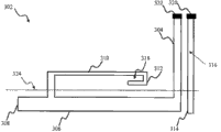
Fig. 3 is the plan view from above (settle with the plane before folding and show) of main antenna element.
Fig. 4 is configured to according to the embodiment of Fig. 1 to 3 configuration and the drawing of being coupled to the measured input trip loss that the exemplary five frequency band main antenna equipment of capsule conductive cap obtain for following: (i) measure in free space; (ii) measure on head, right cheek side according to CTIA3.1; And (iii) according to CTIA 3.1 on the head side, hand measures right cheek is other.
Fig. 5 is configured to according to the embodiment of Fig. 1 to 3 configuration and the drawing of being coupled to the gross efficiency that the exemplary five frequency band main antenna equipment of conductive cap obtain for following: (i) measure in free space; (ii) measure on head, right cheek side according to CTIA 3.1; And (iii) according to CTIA 3.1 on the head side, hand measures right cheek is other.
Fig. 6 is the drawing of the envelope correlation coefficient between main antenna and diversity antenna (ECC) that obtains for the following exemplary multi-frequency band antenna device that is configured to according to the embodiment of Fig. 1 configuration: (i) measure in free space; (ii) measure on head, right cheek side according to CTIA3.1; And (iii) according to CTIA 3.1 on the head side, hand measures right cheek is other.
This paper disclose all graphic be Pulse Finland company
 All rights reserved for Copyright 2011.
Embodiment
With reference now to accompanying drawing,, wherein same numeral refers to same section all the time.
As used herein, term " antenna ", " antenna system ", " antenna assembly " and " multiband antenna " refer to (being not limited to) and incorporate into and reception is arranged/launch and/or propagate arbitrary equipment or the system of the discrete component of one or more electromagnetic radiation frequency bands, a plurality of element or one or more element arrays.Radiation can have polytype, and for example microwave, millimeter wave, radio frequency, Digital Modulation, simulation, analog/digital are encoded, digital coding millimeter wave energy, or similar type.
As used herein, term " plate " and " substrate " refer to and are not limited to can settle on it arbitrary general planar or curved surface or assembly of other assembly substantially.For instance, substrate can comprise that (for example, FR4), semi-conduction nude film or wafer, or the surface of shell or other device assembly even, and can be rigidity substantially, be perhaps flexible to the single or multiple lift printed circuit board (PCB) at least to a certain extent.
Term " frequency range ", " frequency band " and " frequency domain " refer to arbitrary frequency range that (being not limited to) is used for transmitting signal.These a little signals can transmit according to one or more standards or wireless air interface.
as used herein, term " mancarried device ", " mobile computing device ", " client terminal device ", no matter " portable computing " and " end user's device " (is desktop including (but not limited to) personal computer (PC) and microcomputer, on knee or other), set-top box, personal digital assistant (PDA), handheld computer, personal communicator, flat computer, portable navigation is auxiliary, the device of equipment J2ME, cellular phone, smart phone, individual's integrated communicaton or entertainment device, or be to install arbitrary other device of interchange of data with network or another on literal.
In addition, as used herein, term " radiator ", " radiator plane " and " radiant element " refer to (being not limited to) and can serve as and receive and/or the element of the part (for example, its antenna or a part) of the system of emission radio-frequency electromagnetic radiation.
Term " RF presents ", " presenting ", " feed conductor " and " feed network " refer to (being not limited to) can import into/spread out of between RF energy signal and one or more Connection Elements (for example radiator) transmit energy, transforming impedance, the characteristic of strengthening the property and any energy conductor and the coupling element that meet impedance property.
As used herein, term " top ", " bottom ", " side ", " on ", D score, " left side ", " right side " and similar terms only represent an assembly about relative position or the geometry of another assembly, and never represent absolute reference system or any required orientation.For instance, in fact " top " of assembly part can reside in when described assembly is installed to another device (for example, being installed to the bottom side of PCB) below one " bottom " part.
as used herein, term " wireless " means any wireless signal, data, communication or other interface, comprise (being not limited to) Wi-Fi, bluetooth, 3G (for example, 3GPP, 3GPP2 and UMTS), HSDPA/HSUPA, TDMA, CDMA (for example, IS-95A, WCDMA etc.), FHSS, DSSS, GSM, PAN/802.15, WiMAX (802.16), 802.20, arrowband/FDMA, OFDM, PCS/DCS, Long Term Evolution (LTE) or LTE senior (LTE-A), TD-LTE, analogue cellular, CDPD, such as satellite systems such as GPS, millimeter wave or microwave system, optics, acoustics and infrared (namely, IrDA).
General introduction
The present invention one remarkable aspect in provide a kind of at the multi-frequency band antenna device that uses of mobile radio apparatus with conduction capsule.The one exemplary embodiment of antenna equipment described herein has advantageously provided complexity and the cost of comparing reduction with the prior art solution, and the antenna performance of improving.In one embodiment, described antenna equipment comprises the main antenna radiator on an end that is placed in the device capsule, and is placed in diversity or multiple-input and multiple-output (MIMO) antenna radiator on the opposite end.Mobile radio apparatus (for example comprises the metal capsule, all-metal or insulated metal carrier), it comprises a main portion and two antenna cover parts (cover), and described antenna cover part is sealed respectively described major component and diversity antenna radiant element substantially fully.Two radomes partly separate with the primary seal shell by narrow gap, and extend along the circumference of device in described narrow gap.In order to reduce the loss that brings due to during operation disposal, the surface of crown cap can comprise non-conductive layer, for example plastic film.
The main antenna radiator comprises the loose coupling antenna, and it is also referred to as loop aerial.Presenting of main antenna is connected to device RF feed structure, therefore only needs main antenna radiator and single connection of installing between electronic component.The main portion of device conduction capsule is connected to ground connection in one or more precalculated positions.In one embodiment, main portion is located ground connection at four points settling along the longitudinal axis of capsule substantially (two of every sides, on each end one).In another embodiment, for example using extra earth point near place, device side.
Therefore the cover part loose coupling that the covering main antenna is presented forms the passive antenna resonator to feed element.In some embodiments, radome is connected to the device ground plane, in order to adjust the radiation efficiency of antenna resonant frequency, widen antenna bandwidth and enhancing antenna in low-frequency band.
Advantageously, feed element is to surrounding feed element and making described cover to operate under low frequency as the passive antenna resonator as the coupling that is grounded (short circuit) metallization cover of the part of metallization phone capsule.In addition, the coupling of main antenna described herein and diversity antenna auto levelizer electronic component is simplified greatly, because only need the single connection (but being not limited to single presenting) of presenting.
In a particular, settle high frequency band parasitic resonators structure close to the direct feeding radiation device structure of feed element radiator, so that the widen antenna bandwidth of operation.Described parasitic structure arrives ground connection along a side location and the plate bonding of device capsule.
Also disclosed method tuning and the described antenna equipment of operation.
The detailed description of one exemplary embodiment
The various embodiment of equipment of the present invention and method and the detailed description of variant are provided now.Although mainly discuss in the context of mobile device, equipment and method that this paper discusses are not limited.In fact, many equipment described herein and method are useful in the complex antenna of arbitrary number, no matter are with mobile device or fixture (for example, base station or Femto cell), honeycomb fashion or other person is associated.
Exemplary antenna equipment
Referring now to Fig. 1 to 3,, describe the various embodiment of radio antenna apparatus of the present invention in detail.Present an exemplary configuration for the antenna equipment that uses at mobile radio apparatus in Fig. 1.Host mobility device 100 comprises outside capsule 101, and it has width 110 and length 112, and by metal manufacturings such as aluminium, steel, copper or other appropriate alloy.Should be appreciated that to have rectangular shape substantially although this device is shown as, the present invention can have the device of other form factor (for example, square, oval etc.) and put into practice.
The printed circuit board (PCB) (PCB) that comprises radio frequency electric element and ground plane is placed in device 100.In a variant, capsule 101 is to use the plastic carrier structure with the metallization conductive layer (for example, copper alloy) that is placed on its outer surface to make.
As shown in Figure 1, capsule 101 comprises a main portion 102, and two end shield parts, i.e. main antenna end shield 104 and diversity antenna end shield 106.In a variant, only use single end shield (for example, 104), and main portion comprises two parts 102,106.In the embodiment in figure 1, the main side cover is settled close to the bottom end of radio device 100, and the top end of diversity end shield cladding system.The length 124 of each in main antenna end shield 104 and diversity antenna end shield 106,126 is about 13mm (0.5 inch), but can be worth to obtain equal success with other.In a variant, end shield 104,106 is settled close to left side and the right side of device.
In one approach, end shield is from the solid metal manufacturing, and with feed element interval one preset distance (being typically about 1mm).In other method, end shield comprises the metal that is coated with plastics of making by any suitable method of manufacture (for example, laser straight connecting structure (LDS)).In this variant, plastics thickness provides the enough gaps between metal cap part and feed structure, therefore, does not need extra interval.
The first end shield 104 separates with main portion 102 by gap 122, and another end shield 106 separates with main portion 102 by gap 130.In the embodiment shown in fig. 1, exemplary capsule 101 is that 57mm (2.3 inches) is wide, 120mm (4.7 inches) long and 10mm (0.4 inch) is thick.Gap 122,130 is respectively 3mm (0.118 inch) and 1.5mm (0.069 inch) is wide.The tuning of antenna resonant frequency, bandwidth and radiation efficiency realized in gap 122.Usually, narrower gap is corresponding to than low resonant frequency, more inefficient and than narrow bandwidth.The those skilled in the art will understand according to the present invention, and above size is corresponding to a specific antenna/device embodiment, and be based on particular and configure, and therefore wider principle of the present invention only will be described.
The main portion 102 of capsule in a plurality of positions 118,128,119,129 places are connected to ground plane device (not shown), in order to realize good coupling and minimize static discharge (ESD) problem.In the embodiment in figure 1, earthing position is to settle along the longitudinal axis of capsule, wherein two (2) persons in four (4) individual positions (near near the position 118 bottom end and the position 128 top end) are the top surface ground connection of capsule, and both (near near the zone 119 bottom end and the zone 129 top end) 118, the 128 lower surface ground connection with capsule in described position.Grounding connection 118,119,128, the 129th is realized via any method of being suitable for producing high-quality ground connection, including (but not limited to) scolder or brazing connection, earthing screw, fixture, spring loaded pin etc.
In a variant, settle extra earthing contact (not shown) along left side and the right side of main portion, in order to minimize the potential generation of undesirable resonance, and then improve the robustness of antenna operation.
Main antenna end shield 104 is connected to PCB ground connection at ground structure 121 places.As shown in the embodiment of Fig. 1, ground structure 121 is connected to primary seal shell part 102 with end shield 104, in order to realize end shield 104 ground connection.In another embodiment, ground structure 121 comprises the direct connection of auto levelizer PCB ground connection by means of the cable of electric wire, trace or flexible cable or other type.The position of ground structure 121 is through selecting so that form resonance under want frequency in the current-carrying part of end shield 104.
In certain embodiments, diversity antenna 116 comprises the capacitive feed unipole antenna, for example describes in exercise question that way of reference is in full incorporated this paper into discloses case for No. 2011/101534 PCT patent of " possessing the antenna (ANTENNA PROVIDED WITH COVERRADIATOR) that cover radiator ".
Referring now to Fig. 2,, an embodiment of the feed element of detail display and description antenna of the present invention.Antenna feed structure 202 comprises direct feed element 208, and it is coupled to the device feed port via feed structure 204.The direct feeding radiation device of embodiment shown in Figure 2 is parallel to distolateral (not shown) of main side cover 104 and settles, and (in this embodiment approximately 1mm gap) with interval in order to enough electromagnetic coupled are provided.Conduction end shield 104 is presented via feed element 208 electromagnetic coupled auto levelizers, and then produces the parasitic resonators in low-frequency range.In the antenna embodiment of Fig. 1 to 2, feed structure 202 is configured to resonance under the frequency of 900MHz, 1800MHz, 1900MHz and 2100MHz, and end shield 104 resonance under about 850MHz.
In one embodiment, antenna feed structure 202 comprises the feed structure of parasitic couplings, it is electrically connected to primary seal shell part (or PCB ground connection) via ground structure 120, and forms the resonance of the parasitic couplings in high-frequency range, and then increases the antenna operation bandwidth.
As used herein, term " low frequency " and " high frequency " are in order to be described in respectively on frequency lower than the second scope and can to contain the first frequency scope of a plurality of frequency bands.In an exemplary embodiment, low scope extends to approximately 950MHz from about 800MHz, and height or upper frequency range extend to approximately 2700MHz from about 1700MHz.Yet disclosure described herein is not limited to this, and can use other band configurations (comprise the band configurations that overlap each other) consistent with the present invention based on application-specific.The main antenna equipment 114 that comprises feed element 202 and main side cover radiator 104 comprises the loose coupling antenna structure, and it is also referred to as " loop aerial ".Loop aerial is to form by direct feeding radiation device 208 being electromagnetically coupled to the conduction end shield through short circuit of sealing radiator in one embodiment, and described end shield surrounds feed element and in fact as the part of metallization phone capsule.In one embodiment, advantageously only need single electrical connection the (that is, present connect 204) between device PCB and antenna radiator, and then simplified and made and structure.
Fig. 3 explanation be used for the loose coupling antenna equipment (for example, the antenna 114 of Fig. 1) the main antenna radiator that uses together (for example, radiator 202 in Fig. 2) a one exemplary embodiment, it settles to show with the plane, is namely folding with before being used for being arranged on mobile device 100.Radiator structure 302 comprises direct feeding radiation device part 306,308 (being connected to device feed port 322 via feed structure 304) and forms therein the C element 310,312 of slit 318.When mounted, along dotted line 324 folded antenna radiators 302, make radiator structure 306,308 and C element 310,312 be perpendicular to one another in capsule and settle at device.In one embodiment, radiator 302 further comprises parasitic antenna 314, and it is connected to device ground connection via ground structure 320.The total length of all radiator elements (304,306,308,310,312) determines the first resonance frequency F L1 in low-frequency range.The slit 318 of the design forming by feed element produces first resonance frequency (FH1) of high frequency bands.The end of radiator structure 308 divide in order to the first harmonic of low-band resonance be tuned in high frequency band, and then form the second high-frequency resonant (FH2).
To understand according to the present invention as the those skilled in the art, the radiator structure of Fig. 3 presents an one exemplary embodiment, and can use many other antenna radiator configurations.For instance, the length of parasitic radiator 314 be can reduce, radiator 314 and antenna radiator element 310,312 fully coplanar and settle made.
Performance
Fig. 4 to 6 presents this assignee to the simulation of exemplary antenna equipment of structure and the results of property that test period obtains according to one embodiment of present invention.
Fig. 4 is configured to be similar to the embodiment that Fig. 1 to 3 describes and the drawing of the trip loss S11 that becomes along with frequency (take dB as unit) that the five frequency band multiband antennas of constructing records for following measurement: (i) free space; (ii) measure on head, right cheek side according to the CTIA3.1 standard; And (iii) measure on the head side according to CTIA 3.1 standards, at the other device that grasps of right cheek.
Five antenna frequency bands in this sample comprise two 850MHz and 900MHz low-frequency band and three top frequency bands (that is, 1,710-1,880MHz, 1,850-1,990MHz and 1,920-2,170MHz).Mark the border of exemplary lower band in Fig. 4 with the solid line of sign 402 appointments, and marked the border of high frequency band with the line of sign 404 appointments.
Correspond respectively to sign 410,420,430 curves that mark the measurement of carrying out in following situation in Fig. 4: (i) in free space; (ii) according to CTIA 3.1 standards on head, right cheek side; And (iii) according to CTIA 3.1 standards on the head side, at the other device that grasps of right cheek.
The digital proof that presents in Fig. 4 comprise that the exemplary antenna of primary feed and loose coupling conduction end shield radiator has advantageously reduced free space losss, especially in lower frequency ranges (herein, 770MHz is to 950MHz).In addition, the high frequency bandwidth (approximately 460MHz) of the loose coupling main antenna of configuration has advantageously surpassed the high frequency bandwidth of comparing with the crown cap antenna solution of prior art according to the present invention.
The exemplary antenna isolated data (not shown) that this assignee obtains has disclosed the antenna isolation at approximately 9dB, the 17dB in bottom and upper frequency range between main antenna and diversity antenna.The isolation of this increase has advantageously reduced is installing the potential ill-effect that operating period brings due to for example static discharge (ESD).
Fig. 5 presents the data that record efficient about the antenna identical with the antenna of above describing with respect to Fig. 4.The efficient of antenna (take dB as unit) is defined as the decimal logarithm of radiant power and the ratio of input power:

The efficient of zero (0) dB is corresponding to desirable theoretical radiator, and wherein all input powers are with the form radiation of electromagnetic energy.
The measurement that presents in Fig. 5 is following carrying out: (i) free space, by describing with the curve of 510,512 expressions; (ii) measure on head, right cheek side according to CTIA 3.1 standards, by describing with the curves of 520,522 expressions; And (iii) measure on the head side according to CTIA 3.1 standards, hand is by right cheek, by describing with the curves of 530,532 expressions.
The gross efficiency that presents in Fig. 5 measure show-3 in lower band and--4 in free space efficient between 1dB and high frequency band and-free space efficient between 2dB.Showed in the situation that exist dielectric to load the efficiency measurement (curve 520,522,530,532) that carries out the Efficiency Decreasing of comparing with free space measurement (with the curves of 510,512 expressions).Yet when comparing with the capacitively coupled diversity antenna of prior art, the Efficiency Decreasing of loose coupling conduction end shield antenna of the present invention is less substantially, especially in the frequency range from 820MHz to 960MHz.Relatively having proved with the capacitive feed antenna of prior art between described two antenna responses compared, and main loose coupling end shield antenna of the present invention is in free space and in the higher efficient (3dB is to 7dB) substantially on head side.
Fig. 6 presents the data about the envelope correlation coefficient that records (ECC) between the capacitive couplings one pole diversity antenna of the exemplary embodiment of main loose coupling antenna of the present invention and prior art.To identify 602,604 curves that mark corresponding to the measurement of carrying out in free space, identifying 612,614 curves that mark corresponding to the measurement of carrying out on head, right cheek side according to CTIA 3.1 standards, and with identify 622,624 curves that mark corresponding to according to CTIA 3.1 standards on the head side, the measurement carried out at right cheek other (BHHR) of hand.Data shown in Figure 6 have advantageously represented in all configurations at (approximate reproduction installing typical operation conditions between the operating period) under high frequency and when operating in the BHHR CTIA 3.1 configuration low ECC in lower band between main antenna and diversity antenna.
The digital proof that presents in Fig. 4 to 6 comprise that the multiband antenna of the loose coupling conduction end shield that serves as parasitic resonators can operate in wide frequency ranges, for example cover from 824 to 960MHz exemplary lower band and from 1,710MHz to 2, the high frequency band of 170MHz is compared with the capacitance coupling antenna design of prior art simultaneously and has been kept low loss and high radiation efficiency.
In addition, the multiband antenna of the configuration needs match circuit (and then save cost and space) not advantageously according to the present invention, and comprise the passive structures that does not use active switching, therefore further reduce radiation loss, antenna size and cost.Also utilized the single connection of auto levelizer electronic component, this has simplified the antenna installation and has increased the operation robustness.The isolation of the bandwidth that especially increases under lower frequency, lower loss and improvement has allowed in the situation that the antenna Multiband-operation of all-metal appliance cover is kept and performance non-metallic or that only partially metallised appliance cover is identical, device size and/or antenna cost simultaneously.
This ability advantageously allows to have the operation of portable computing on some mobile frequency bands of individual antenna, for example GSM850, GSM900, GSM1900, GSM1800, PCS-1900 and LTE/LTE-A and/or WiMAX (ieee standard 802.16) frequency band.In addition, the use of independent tuning branch makes it possible to form higher-order antenna resonance, therefore realizes the antenna operation in extra high frequency band (for example, 2500-2600MHz frequency band).This ability further especially expands to antenna use Wi-Fi (802.11) and extra LTE/LTE-A frequency band.As be understood by those skilled in the art that, frequency band given above forms and can revise according to the needs of desired application-specific, and can support/use additional band equally.
To recognize, although describe some aspect of the present invention in view of the particular order of the step of method, these descriptions only illustrate wider method of the present invention, and can revise according to the needs of application-specific.Some step is become unnecessary or optional.In addition, can add to the embodiment that discloses some step or functional, or replace the execution order of two or more steps.In the present invention who all these type of variations is considered as being included in this paper announcement and advocates.
In one approach, can use half cup (half-cup) embodiment, make on a side (for example, the top side that generally includes display of device) and do not have metal.
Although detailed description is above showed, is described and points out the novel feature that is applied to various embodiment of the present invention, but will understand, without departing from the invention, the those skilled in the art can make various omissions, replacement and change on the form of illustrated device or process and details.Foregoing description is that optimal mode of the present invention is carried out in current expection.This description never means restrictive, but should be considered as illustrating General Principle of the present invention.Should determine scope of the present invention with reference to claims.
Claims (35)
1. antenna equipment, it comprises:
The main antenna radiator, it has single feed point and connects;
The diversity antenna element;
Wherein said antenna equipment is configured to utilize at least a portion of metal capsule of host apparatus as parasitic resonators; And
Wherein said antenna equipment can receive signal in a plurality of frequency bands in bottom and upper operating frequency range at least.
2. antenna equipment according to claim 1, wherein said antenna equipment does not comprise any tuning circuit or switch.
3. antenna equipment according to claim 1, wherein said host apparatus comprises the mobile honeycomb phone, and described frequency band is complied with mutually with those frequency bands of appointment in Long Term Evolution LTE wireless standard at least in part.
4. antenna equipment according to claim 1, wherein said antenna equipment use described main antenna radiator to form the first parasitic resonators, and use described diversity antenna element to form the second parasitic resonators.
5. frequency communication devices, it comprises:
Electronic element assembly, it comprises ground plane and feed port;
The outside capsule of at least part of conduction, it comprises the main portion of sealing described electronic element assembly, and seals the first end shield of the first antenna radiator, described first day beta radiation utensil has the feed structure that is connected to described feed port;
Wherein:
Described the first antenna radiator is configured to operate at least the first frequency band; And
Described the first end shield is connected to described ground plane at the primary importance place at least, and then forms the first parasitic radiator in the second frequency band.
6. communicator according to claim 5, wherein:
Described the first antenna radiator and described the first parasitic radiator form the first multi-frequency band antenna device; And
Described the first parasitic radiator is configured to widen the bandwidth of operation of described the first multi-frequency band antenna device.
7. communicator according to claim 5, described ground connection being configured to of wherein said the first end shield increases the radiation efficiency of described the first parasitic radiator.
8. communicator according to claim 7, wherein said the first end shield is settled close to the first end of described device.
9. communicator according to claim 8, wherein said outside capsule is by the metal manufacturing.
10. communicator according to claim 9, wherein said outside capsule comprise non-conductive carrier and are placed in conductive layer on described non-conductive carrier.
11. communicator according to claim 9, wherein:
Described main portion is connected to described ground plane at least one position; And
Described the first end shield is realized via described main portion to the described connection of described ground plane.
12. communicator according to claim 9, wherein said the first end shield is connected to described ground plane via direct connection.
13. communicator according to claim 9, wherein said the first end shield separates with described main portion by the gap, and described gap is substantially around the circumference of described capsule and extend.
14. communicator according to claim 8, wherein:
Described at least part of conduction capsule further comprises the second end shield of settling close to the second end of described device, described the second end is relative with described first end, described second end shield sealing the second antenna radiator, described second day beta radiation utensil have the feed structure that is connected to described feed port and are configured to and operate in described at least the first frequency band.
15. communicator according to claim 14, wherein:
Described the second end shield is connected to described ground plane at second place place at least, and then forms the second parasitic radiator in described the second frequency band;
Described the second antenna radiator and described the second parasitic radiator form the second multi-frequency band antenna device; And
Described the second parasitic radiator is configured to widen the bandwidth of operation of described the second multi-frequency band antenna device.
16. communicator according to claim 15, wherein said the second end shield separates with described main portion by the second gap, and described the second gap is substantially around the circumference of described capsule and extend.
17. multi-frequency band antenna device that the radio communications set that is used at the outside capsule with at least part of conduction uses, described antenna equipment comprises direct feeding radiation device structure, and described direct feeding radiation device structure has the feedthrough part of the feed port that is configured to be connected to described radio communications set;
Wherein:
Described direct feeding radiation device structure can operate and be configured to be electromagnetically coupled to the end shield part of described outside capsule at least the first frequency band;
Described end shield is electrically connected to the ground plane of described radio device via ground structure;
Described ground connection being configured to of described end shield widened the bandwidth of operation of described multi-frequency band antenna device; And
Described direct feeding radiation device structure is cooperated to form the parasitic feeding radiation device of described antenna equipment in the second frequency band by the described sealing of described end shield and the described ground connection of described end shield.
18. antenna equipment according to claim 17, described ground connection being configured to of wherein said end shield increases the radiation efficiency of described multi-frequency band antenna device.
19. antenna equipment according to claim 17, wherein said the second frequency band is lower than described the first frequency band.
20. antenna equipment according to claim 17, wherein said end shield are configured to substantially the described direct feeding radiation device structure of sealing on five sides at least.
21. antenna equipment according to claim 17, wherein said ground plane is by predetermined ground connection space and described direct feeding radiation device spacing structure.
22. antenna equipment according to claim 17, wherein said direct feeding radiation device structure comprises the first that is parallel to substantially described ground plane and configures, and the second portion that configures perpendicular to described ground plane substantially.
23. antenna equipment according to claim 17, wherein said antenna comprises parasitic radiator, and electromagnetic coupled resonance is settled and be configured to form to described parasitic radiator at least the three frequency band close to described feedthrough part.
24. antenna equipment according to claim 23, wherein said the second frequency band is lower than described the 3rd frequency band.
25. antenna equipment according to claim 17, wherein said ground structure comprises at least a portion of the main portion of described outside capsule.
26. antenna equipment according to claim 17, wherein said ground structure are included in the direct connection of described ground plane.
27. the method for the bandwidth of operation of the multiband antenna that an expansion is used in the radio device of the outside capsule with at least part of conduction, described method comprises:
By between the feed port that realizes the first radiator and described radio device be electrically connected to and at least the first frequency band to described the first radiator structure energy supply; And
Operate at least the second frequency band the second antenna radiator structure energy supply by following:
(i) described the second radiator structure is electromagnetically coupled to described feed port; And
(ii) realize being connected electrical ground between the ground plane of described the second radiator structure and described radio device.
28. method according to claim 27 wherein realizes described connection electrical ground via the direct connection to described ground plane.
29. method according to claim 27, wherein:
Described the second radiator structure comprises the end shield part of described outside capsule; And
Described end shield part is connected to described ground plane at the primary importance place at least, and described primary importance is through selecting to widen the bandwidth of operation of described multiband antenna.
30. method according to claim 29, wherein said end shield partly are configured to the described antenna equipment of sealing at least five sides substantially.
31. method according to claim 29, described ground connection being configured to of wherein said end shield increases the radiation efficiency of described multiband antenna.
32. one kind is used for the antenna radiator structure that uses at wireless device, described structure comprises:
Direct feeding radiation element, itself and feed structure electric connection; And
The second radiant element, it has the slit that is formed at wherein;
When being configured in being arranged on the host apparatus capsule, wherein said direct feeding radiation element and described the second radiant element settling on vertical orientation substantially.
33. structure according to claim 32, it further comprises and is suitable for the parasitic antenna that is communicated with the ground connection of described host apparatus, and described parasitic antenna is configured to place and resonance under the frequency except the frequency of described direct feeding radiation element or described the second radiant element close to described feed structure.
34. structure according to claim 32, wherein said slit are configured to produce the first resonance frequency of the high frequency band that joins with described structurally associated.
35. structure according to claim 34, wherein said direct feeding radiation element comprise that the end divides, described end divide in order to the first harmonic of low-band resonance be tuned in described high frequency band, therefore form the second high-frequency resonant.
Applications Claiming Priority (2)
| Application Number | Priority Date | Filing Date | Title |
|---|---|---|---|
| US13/331,802 | 2011-12-20 | ||
| US13/331,802 US9531058B2 (en) | 2011-12-20 | 2011-12-20 | Loosely-coupled radio antenna apparatus and methods |
Publications (2)
| Publication Number | Publication Date |
|---|---|
| CN103178325A true CN103178325A (en) | 2013-06-26 |
| CN103178325B CN103178325B (en) | 2016-08-10 |
Family
ID=47632726
Family Applications (1)
| Application Number | Title | Priority Date | Filing Date |
|---|---|---|---|
| CN201210560866.9A Active CN103178325B (en) | 2011-12-20 | 2012-12-20 | Loose coupling radio antenna apparatus and method |
Country Status (3)
| Country | Link |
|---|---|
| US (1) | US9531058B2 (en) |
| EP (1) | EP2608314B1 (en) |
| CN (1) | CN103178325B (en) |
Cited By (12)
| Publication number | Priority date | Publication date | Assignee | Title |
|---|---|---|---|---|
| CN104347931A (en) * | 2013-08-05 | 2015-02-11 | 联想(北京)有限公司 | Adjustable multi-band antenna |
| CN105098352A (en) * | 2015-07-31 | 2015-11-25 | 瑞声精密制造科技(常州)有限公司 | Mobile terminal |
| CN106384875A (en) * | 2016-11-22 | 2017-02-08 | 深圳市天威讯无线技术有限公司 | Antenna structure capable of flexibly adjusting antenna use frequency |
| CN106558755A (en) * | 2015-09-29 | 2017-04-05 | 深圳富泰宏精密工业有限公司 | Antenna modules and the radio communication device using the antenna modules |
| CN106602222A (en) * | 2016-12-15 | 2017-04-26 | 奇酷互联网络科技(深圳)有限公司 | Mobile terminal and antenna device thereof |
| CN107293843A (en) * | 2016-03-31 | 2017-10-24 | 上海莫仕连接器有限公司 | WIFI antenna assemblies |
| TWI651889B (en) * | 2016-03-31 | 2019-02-21 | 莫仕有限公司 | Antenna device |
| CN110620289A (en) * | 2018-06-19 | 2019-12-27 | 海信集团有限公司 | Radio frequency device and terminal equipment |
| CN110832697A (en) * | 2017-07-06 | 2020-02-21 | 卡姆鲁普股份有限公司 | Dual strip antenna with dome shaped radiator |
| CN111384588A (en) * | 2018-12-27 | 2020-07-07 | 宏碁股份有限公司 | Multi-frequency antenna |
| US11009538B2 (en) | 2018-02-27 | 2021-05-18 | Applied Materials, Inc. | Micro resonator array system |
| CN113078447A (en) * | 2015-07-28 | 2021-07-06 | 三星电子株式会社 | Electronic device and portable communication device |
Families Citing this family (25)
| Publication number | Priority date | Publication date | Assignee | Title |
|---|---|---|---|---|
| US9502776B2 (en) * | 2012-04-09 | 2016-11-22 | Maxtena | Antenna surrounded by metal housing |
| US9147932B2 (en) * | 2012-10-08 | 2015-09-29 | Apple Inc. | Tunable multiband antenna with dielectric carrier |
| CN110854509B (en) * | 2012-12-21 | 2022-03-25 | 诺基亚技术有限公司 | Apparatus for wireless communication |
| CN104969412B (en) * | 2013-02-06 | 2018-11-16 | 瑞典爱立信有限公司 | Antenna assembly for Multiband-operation |
| TWI590525B (en) * | 2013-06-04 | 2017-07-01 | 群邁通訊股份有限公司 | Antenna structure and wireless communication device using same |
| KR101544698B1 (en) * | 2013-12-23 | 2015-08-17 | 주식회사 이엠따블유 | Intenna |
| US9774073B2 (en) * | 2014-01-16 | 2017-09-26 | Htc Corporation | Mobile device and multi-band antenna structure therein |
| US9674320B2 (en) | 2014-08-22 | 2017-06-06 | Google Inc. | Systems and methods for enabling radio-frequency communication of a modular mobile electronic device |
| US10096887B2 (en) * | 2014-09-15 | 2018-10-09 | Blackberry Limited | Mobile device with tri-band antennas incorporated into a metal back side |
| US9912059B2 (en) | 2014-10-21 | 2018-03-06 | Google Llc | Proximity coupled multi-band antenna |
| CN204720561U (en) * | 2015-05-29 | 2015-10-21 | 瑞声精密制造科技(常州)有限公司 | Antenna system of mobile phone |
| TWI572089B (en) * | 2015-07-16 | 2017-02-21 | 和碩聯合科技股份有限公司 | Wireless communication apparatus |
| CN106450658A (en) | 2015-08-07 | 2017-02-22 | 微软技术许可有限责任公司 | Antenna device for electronic equipment |
| US9813103B2 (en) | 2015-09-15 | 2017-11-07 | Microsoft Technology Licensing, Llc | Enhanced multi-band multi-feed antennas and a wireless communication apparatus |
| US10374287B2 (en) * | 2015-10-26 | 2019-08-06 | AAC Technologies Pte. Ltd. | Antenna system with full metal back cover |
| CN105977611A (en) * | 2015-12-11 | 2016-09-28 | 乐视移动智能信息技术(北京)有限公司 | Antenna applied to all-metal shell and mobile terminal applied to all-metal shell |
| CN105977612A (en) * | 2015-12-15 | 2016-09-28 | 乐视移动智能信息技术(北京)有限公司 | Ultra-wideband parasitic antenna and mobile terminal |
| WO2017142558A1 (en) * | 2016-02-19 | 2017-08-24 | Hewlett-Packard Development Company, L.P. | Antenna and cap |
| CN107508034B (en) * | 2017-09-14 | 2024-05-17 | 深圳传音制造有限公司 | Intelligent equipment |
| GB2571279B (en) | 2018-02-21 | 2022-03-09 | Pet Tech Limited | Antenna arrangement and associated method |
| DE102018122423A1 (en) * | 2018-09-13 | 2020-03-19 | Endress+Hauser SE+Co. KG | Device for transmitting signals from an at least partially metallic housing |
| TWI688162B (en) * | 2018-11-23 | 2020-03-11 | 宏碁股份有限公司 | Multi-band antenna |
| US11342671B2 (en) | 2019-06-07 | 2022-05-24 | Sonos, Inc. | Dual-band antenna topology |
| CN113497350B (en) * | 2020-04-08 | 2022-08-16 | 海信集团有限公司 | Antenna, wireless communication module and terminal |
| CN113690589A (en) * | 2021-08-23 | 2021-11-23 | 南昌逸勤科技有限公司 | Antenna device and wireless communication equipment |
Citations (5)
| Publication number | Priority date | Publication date | Assignee | Title |
|---|---|---|---|---|
| CN1669182A (en) * | 2002-09-10 | 2005-09-14 | 弗拉克托斯股份有限公司 | Coupled multi-band antenna |
| US7623078B2 (en) * | 2006-12-15 | 2009-11-24 | Apple Inc. | Antenna for portable electronic device wireless communications adapter |
| CN101626115A (en) * | 2008-06-10 | 2010-01-13 | 北电网络有限公司 | Improvements relating to antennas |
| US7830327B2 (en) * | 2007-05-18 | 2010-11-09 | Powerwave Technologies, Inc. | Low cost antenna design for wireless communications |
| WO2011076582A1 (en) * | 2009-12-21 | 2011-06-30 | Lite-On Mobile Oyj | An antenna arrangement |
Family Cites Families (539)
| Publication number | Priority date | Publication date | Assignee | Title |
|---|---|---|---|---|
| US2745102A (en) | 1945-12-14 | 1956-05-08 | Norgorden Oscar | Antenna |
| US4004228A (en) | 1974-04-29 | 1977-01-18 | Integrated Electronics, Ltd. | Portable transmitter |
| DE2538614C3 (en) | 1974-09-06 | 1979-08-02 | Murata Manufacturing Co., Ltd., Nagaokakyo, Kyoto (Japan) | Dielectric resonator |
| US3938161A (en) | 1974-10-03 | 1976-02-10 | Ball Brothers Research Corporation | Microstrip antenna structure |
| US4054874A (en) | 1975-06-11 | 1977-10-18 | Hughes Aircraft Company | Microstrip-dipole antenna elements and arrays thereof |
| US4123758A (en) | 1976-02-27 | 1978-10-31 | Sumitomo Electric Industries, Ltd. | Disc antenna |
| US4031468A (en) | 1976-05-04 | 1977-06-21 | Reach Electronics, Inc. | Receiver mount |
| JPS583405B2 (en) | 1976-09-24 | 1983-01-21 | 日本電気株式会社 | Antenna for small radio equipment |
| US4069483A (en) | 1976-11-10 | 1978-01-17 | The United States Of America As Represented By The Secretary Of The Navy | Coupled fed magnetic microstrip dipole antenna |
| US4131893A (en) | 1977-04-01 | 1978-12-26 | Ball Corporation | Microstrip radiator with folded resonant cavity |
| CA1128152A (en) | 1978-05-13 | 1982-07-20 | Takuro Sato | High frequency filter |
| US4201960A (en) | 1978-05-24 | 1980-05-06 | Motorola, Inc. | Method for automatically matching a radio frequency transmitter to an antenna |
| US4313121A (en) | 1980-03-13 | 1982-01-26 | The United States Of America As Represented By The Secretary Of The Army | Compact monopole antenna with structured top load |
| JPS5761313A (en) | 1980-09-30 | 1982-04-13 | Matsushita Electric Ind Co Ltd | Band-pass filter for ultra-high frequency |
| US4356492A (en) | 1981-01-26 | 1982-10-26 | The United States Of America As Represented By The Secretary Of The Navy | Multi-band single-feed microstrip antenna system |
| US4370657A (en) | 1981-03-09 | 1983-01-25 | The United States Of America As Represented By The Secretary Of The Navy | Electrically end coupled parasitic microstrip antennas |
| US5053786A (en) | 1982-01-28 | 1991-10-01 | General Instrument Corporation | Broadband directional antenna |
| US4431977A (en) | 1982-02-16 | 1984-02-14 | Motorola, Inc. | Ceramic bandpass filter |
| JPS59125104U (en) | 1983-02-10 | 1984-08-23 | 株式会社村田製作所 | outer join structure |
| CA1212175A (en) | 1983-03-19 | 1986-09-30 | Takashi Oda | Double loop antenna for use in connection to a miniature radio receiver |
| US4546357A (en) | 1983-04-11 | 1985-10-08 | The Singer Company | Furniture antenna system |
| JPS59202831A (en) | 1983-05-06 | 1984-11-16 | Yoshida Kogyo Kk <Ykk> | Manufacture of foil decorated molded product, its product and transfer foil |
| FR2553584B1 (en) | 1983-10-13 | 1986-04-04 | Applic Rech Electronique | HALF-LOOP ANTENNA FOR LAND VEHICLE |
| FR2556510B1 (en) | 1983-12-13 | 1986-08-01 | Thomson Csf | PERIODIC PLANE ANTENNA |
| JPS60206304A (en) | 1984-03-30 | 1985-10-17 | Nissha Printing Co Ltd | Production of parabolic antenna reflector |
| US4706050A (en) | 1984-09-22 | 1987-11-10 | Smiths Industries Public Limited Company | Microstrip devices |
| US4742562A (en) | 1984-09-27 | 1988-05-03 | Motorola, Inc. | Single-block dual-passband ceramic filter useable with a transceiver |
| JPS61196603A (en) | 1985-02-26 | 1986-08-30 | Mitsubishi Electric Corp | Antenna |
| JPS61208902A (en) | 1985-03-13 | 1986-09-17 | Murata Mfg Co Ltd | Mic type dielectric filter |
| JPS61245704A (en) | 1985-04-24 | 1986-11-01 | Matsushita Electric Works Ltd | Flat antenna |
| JPS61285801A (en) | 1985-06-11 | 1986-12-16 | Matsushita Electric Ind Co Ltd | Filter |
| US4661992A (en) | 1985-07-31 | 1987-04-28 | Motorola Inc. | Switchless external antenna connector for portable radios |
| US4740765A (en) | 1985-09-30 | 1988-04-26 | Murata Manufacturing Co., Ltd. | Dielectric filter |
| US4954796A (en) | 1986-07-25 | 1990-09-04 | Motorola, Inc. | Multiple resonator dielectric filter |
| US4716391A (en) | 1986-07-25 | 1987-12-29 | Motorola, Inc. | Multiple resonator component-mountable filter |
| US4692726A (en) | 1986-07-25 | 1987-09-08 | Motorola, Inc. | Multiple resonator dielectric filter |
| JPS6342501A (en) | 1986-08-08 | 1988-02-23 | Alps Electric Co Ltd | Microwave band-pass filter |
| US4862181A (en) | 1986-10-31 | 1989-08-29 | Motorola, Inc. | Miniature integral antenna-radio apparatus |
| US4835541A (en) | 1986-12-29 | 1989-05-30 | Ball Corporation | Near-isotropic low-profile microstrip radiator especially suited for use as a mobile vehicle antenna |
| US4800392A (en) | 1987-01-08 | 1989-01-24 | Motorola, Inc. | Integral laminar antenna and radio housing |
| US4835538A (en) | 1987-01-15 | 1989-05-30 | Ball Corporation | Three resonator parasitically coupled microstrip antenna array element |
| US4821006A (en) | 1987-01-17 | 1989-04-11 | Murata Manufacturing Co., Ltd. | Dielectric resonator apparatus |
| US4800348A (en) | 1987-08-03 | 1989-01-24 | Motorola, Inc. | Adjustable electronic filter and method of tuning same |
| FI78198C (en) | 1987-11-20 | 1989-06-12 | Lk Products Oy | Överföringsledningsresonator |
| JPH0659009B2 (en) | 1988-03-10 | 1994-08-03 | 株式会社豊田中央研究所 | Mobile antenna |
| US4879533A (en) | 1988-04-01 | 1989-11-07 | Motorola, Inc. | Surface mount filter with integral transmission line connection |
| GB8809688D0 (en) | 1988-04-25 | 1988-06-02 | Marconi Co Ltd | Transceiver testing apparatus |
| US4965537A (en) | 1988-06-06 | 1990-10-23 | Motorola Inc. | Tuneless monolithic ceramic filter manufactured by using an art-work mask process |
| US4823098A (en) | 1988-06-14 | 1989-04-18 | Motorola, Inc. | Monolithic ceramic filter with bandstop function |
| FI80542C (en) | 1988-10-27 | 1990-06-11 | Lk Products Oy | resonator |
| US4896124A (en) | 1988-10-31 | 1990-01-23 | Motorola, Inc. | Ceramic filter having integral phase shifting network |
| JPH02125503A (en) | 1988-11-04 | 1990-05-14 | Kokusai Electric Co Ltd | Small sized antenna |
| JPH0821812B2 (en) | 1988-12-27 | 1996-03-04 | 原田工業株式会社 | Flat antenna for mobile communication |
| JPH02214205A (en) | 1989-02-14 | 1990-08-27 | Fujitsu Ltd | electronic circuit equipment |
| US4980694A (en) | 1989-04-14 | 1990-12-25 | Goldstar Products Company, Limited | Portable communication apparatus with folded-slot edge-congruent antenna |
| JPH0812961B2 (en) | 1989-05-02 | 1996-02-07 | 株式会社村田製作所 | Parallel multi-stage bandpass filter |
| FI84536C (en) | 1989-05-22 | 1991-12-10 | Nokia Mobira Oy | RF connectors for connecting a radio telephone to an external antenna |
| JPH02308604A (en) | 1989-05-23 | 1990-12-21 | Harada Ind Co Ltd | Flat plate antenna for mobile communication |
| US5307036A (en) | 1989-06-09 | 1994-04-26 | Lk-Products Oy | Ceramic band-stop filter |
| US5103197A (en) | 1989-06-09 | 1992-04-07 | Lk-Products Oy | Ceramic band-pass filter |
| US5109536A (en) | 1989-10-27 | 1992-04-28 | Motorola, Inc. | Single-block filter for antenna duplexing and antenna-summed diversity |
| US5363114A (en) | 1990-01-29 | 1994-11-08 | Shoemaker Kevin O | Planar serpentine antennas |
| FI87405C (en) | 1990-02-07 | 1992-12-28 | Lk Products Oy | HOEGFREKVENSFILTER |
| FI84674C (en) | 1990-02-07 | 1991-12-27 | Lk Products Oy | Helix resonator |
| US5043738A (en) | 1990-03-15 | 1991-08-27 | Hughes Aircraft Company | Plural frequency patch antenna assembly |
| US5220335A (en) | 1990-03-30 | 1993-06-15 | The United States Of America As Represented By The Administrator Of The National Aeronautics And Space Administration | Planar microstrip Yagi antenna array |
| FI84211C (en) | 1990-05-04 | 1991-10-25 | Lk Products Oy | Temperature compensation in a helix resonator |
| FI90157C (en) | 1990-05-04 | 1993-12-27 | Lk Products Oy | STOEDANORDNING FOER HELIX-RESONATOR |
| FI85079C (en) | 1990-06-26 | 1992-02-25 | Idesco Oy | DATAOEVERFOERINGSANORDNING. |
| FI88565C (en) | 1990-07-06 | 1993-05-25 | Lk Products Oy | Method for improving the barrier attenuation of a radio frequency filter |
| JPH04103228A (en) | 1990-08-22 | 1992-04-06 | Mitsubishi Electric Corp | Radio repeater and radio equipment |
| US5155493A (en) | 1990-08-28 | 1992-10-13 | The United States Of America As Represented By The Secretary Of The Air Force | Tape type microstrip patch antenna |
| FI88286C (en) | 1990-09-19 | 1993-04-26 | Lk Products Oy | Method of coating a dielectric ceramic piece with an electrically conductive layer |
| US5203021A (en) | 1990-10-22 | 1993-04-13 | Motorola Inc. | Transportable support assembly for transceiver |
| US5166697A (en) | 1991-01-28 | 1992-11-24 | Lockheed Corporation | Complementary bowtie dipole-slot antenna |
| US5231406A (en) | 1991-04-05 | 1993-07-27 | Ball Corporation | Broadband circular polarization satellite antenna |
| FI86673C (en) | 1991-04-12 | 1992-09-25 | Lk Products Oy | CERAMIC DUPLEXFILTER. |
| FI87854C (en) | 1991-04-12 | 1993-02-25 | Lk Products Oy | Method of manufacturing a high frequency filter as well as high frequency filters made according to the method |
| FI88441C (en) | 1991-06-25 | 1993-05-10 | Lk Products Oy | TEMPERATURKOMPENSERAT DIELEKTRISKT FILTER |
| FI90158C (en) | 1991-06-25 | 1993-12-27 | Lk Products Oy | OEVERTONSFREKVENSFILTER AVSETT FOER ETT KERAMISKT FILTER |
| FI88442C (en) | 1991-06-25 | 1993-05-10 | Lk Products Oy | Method for offset of the characteristic curve of a resonated or in the frequency plane and a resonator structure |
| FI88440C (en) | 1991-06-25 | 1993-05-10 | Lk Products Oy | Ceramic filter |
| FI88443C (en) | 1991-06-25 | 1993-05-10 | Lk Products Oy | The structure of a ceramic filter |
| US5210542A (en) | 1991-07-03 | 1993-05-11 | Ball Corporation | Microstrip patch antenna structure |
| US5355142A (en) | 1991-10-15 | 1994-10-11 | Ball Corporation | Microstrip antenna structure suitable for use in mobile radio communications and method for making same |
| US5541617A (en) | 1991-10-21 | 1996-07-30 | Connolly; Peter J. | Monolithic quadrifilar helix antenna |
| US5349700A (en) | 1991-10-28 | 1994-09-20 | Bose Corporation | Antenna tuning system for operation over a predetermined frequency range |
| FI89644C (en) | 1991-10-31 | 1993-10-25 | Lk Products Oy | TEMPERATURKOMPENSERAD RESONATOR |
| US5229777A (en) | 1991-11-04 | 1993-07-20 | Doyle David W | Microstrap antenna |
| ATE154734T1 (en) | 1991-12-10 | 1997-07-15 | Blaese Herbert R | AUXILIARY ANTENNA |
| US5432489A (en) | 1992-03-09 | 1995-07-11 | Lk-Products Oy | Filter with strip lines |
| FI91116C (en) | 1992-04-21 | 1994-05-10 | Lk Products Oy | Helix resonator |
| US5438697A (en) | 1992-04-23 | 1995-08-01 | M/A-Com, Inc. | Microstrip circuit assembly and components therefor |
| US5170173A (en) | 1992-04-27 | 1992-12-08 | Motorola, Inc. | Antenna coupling apparatus for cordless telephone |
| GB2266997A (en) | 1992-05-07 | 1993-11-17 | Wallen Manufacturing Limited | Radio antenna. |
| FI90808C (en) | 1992-05-08 | 1994-03-25 | Lk Products Oy | The resonator structure |
| FI90926C (en) | 1992-05-14 | 1994-04-11 | Lk Products Oy | High frequency filter with switching property |
| FR2695482B1 (en) | 1992-09-10 | 1994-10-21 | Alsthom Gec | Measuring device using a Rogowski coil. |
| JP3457351B2 (en) | 1992-09-30 | 2003-10-14 | 株式会社東芝 | Portable wireless devices |
| JPH06152463A (en) | 1992-11-06 | 1994-05-31 | Fujitsu Ltd | Portable radio terminal equipment |
| FI92265C (en) | 1992-11-23 | 1994-10-10 | Lk Products Oy | Radio frequency filter, whose helix resonators on the inside are supported by an insulation plate |
| US5444453A (en) | 1993-02-02 | 1995-08-22 | Ball Corporation | Microstrip antenna structure having an air gap and method of constructing same |
| FI93504C (en) | 1993-03-03 | 1995-04-10 | Lk Products Oy | Transmission line filter with adjustable transmission zeros |
| FI93503C (en) | 1993-03-03 | 1995-04-10 | Lk Products Oy | RF filter |
| FI94298C (en) | 1993-03-03 | 1995-08-10 | Lk Products Oy | Method and connection for changing the filter type |
| ZA941671B (en) | 1993-03-11 | 1994-10-12 | Csir | Attaching an electronic circuit to a substrate. |
| US5394162A (en) | 1993-03-18 | 1995-02-28 | Ford Motor Company | Low-loss RF coupler for testing a cellular telephone |
| US5711014A (en) | 1993-04-05 | 1998-01-20 | Crowley; Robert J. | Antenna transmission coupling arrangement |
| FI93404C (en) | 1993-04-08 | 1995-03-27 | Lk Products Oy | Method of making a connection opening in the partition wall between the helix resonators of a radio frequency filter and a filter |
| US5532703A (en) | 1993-04-22 | 1996-07-02 | Valor Enterprises, Inc. | Antenna coupler for portable cellular telephones |
| DE69422327T2 (en) | 1993-04-23 | 2000-07-27 | Murata Mfg. Co., Ltd. | Surface mount antenna unit |
| FI99216C (en) | 1993-07-02 | 1997-10-27 | Lk Products Oy | Dielectric filter |
| US5442366A (en) | 1993-07-13 | 1995-08-15 | Ball Corporation | Raised patch antenna |
| EP0637094B1 (en) | 1993-07-30 | 1998-04-08 | Matsushita Electric Industrial Co., Ltd. | Antenna for mobile communication |
| FI95851C (en) | 1993-09-10 | 1996-03-25 | Lk Products Oy | Connection for electrical frequency control of a transmission line resonator and an adjustable filter |
| FI110148B (en) | 1993-09-10 | 2002-11-29 | Filtronic Lk Oy | Multi-resonator radio frequency filter |
| JPH07131234A (en) | 1993-11-02 | 1995-05-19 | Nippon Mektron Ltd | Biresonance antenna |
| FI94914C (en) | 1993-12-23 | 1995-11-10 | Lk Products Oy | Combed helix filter |
| FI95087C (en) | 1994-01-18 | 1995-12-11 | Lk Products Oy | Dielectric resonator frequency control |
| US5440315A (en) | 1994-01-24 | 1995-08-08 | Intermec Corporation | Antenna apparatus for capacitively coupling an antenna ground plane to a moveable antenna |
| FI95327C (en) | 1994-01-26 | 1996-01-10 | Lk Products Oy | Adjustable filter |
| JPH07221536A (en) | 1994-02-08 | 1995-08-18 | Japan Radio Co Ltd | Small antenna |
| FI97086C (en) | 1994-02-09 | 1996-10-10 | Lk Products Oy | Arrangements for separation of transmission and reception |
| US5751256A (en) | 1994-03-04 | 1998-05-12 | Flexcon Company Inc. | Resonant tag labels and method of making same |
| DE69529496D1 (en) | 1994-03-08 | 2003-03-06 | Telit Mobile Terminals Spa | PORTABLE TRANSMITTER AND / OR RECEIVER |
| JPH07249923A (en) | 1994-03-09 | 1995-09-26 | Murata Mfg Co Ltd | Surface mounting type antenna |
| FI95516C (en) | 1994-03-15 | 1996-02-12 | Lk Products Oy | Coupling element for coupling to a transmission line resonator |
| EP0687030B1 (en) | 1994-05-10 | 2001-09-26 | Murata Manufacturing Co., Ltd. | Antenna unit |
| JPH07307612A (en) | 1994-05-11 | 1995-11-21 | Sony Corp | Plane antenna |
| FI98870C (en) | 1994-05-26 | 1997-08-25 | Lk Products Oy | Dielectric filter |
| US5557292A (en) | 1994-06-22 | 1996-09-17 | Space Systems/Loral, Inc. | Multiple band folding antenna |
| US5757327A (en) | 1994-07-29 | 1998-05-26 | Mitsumi Electric Co., Ltd. | Antenna unit for use in navigation system |
| FR2724274B1 (en) | 1994-09-07 | 1996-11-08 | Telediffusion Fse | FRAME ANTENNA, INSENSITIVE TO CAPACITIVE EFFECT, AND TRANSCEIVER DEVICE COMPRISING SUCH ANTENNA |
| FI96998C (en) | 1994-10-07 | 1996-09-25 | Lk Products Oy | Radio frequency filter with Helix resonators |
| CA2164669C (en) | 1994-12-28 | 2000-01-18 | Martin Victor Schneider | Multi-branch miniature patch antenna having polarization and share diversity |
| US5517683A (en) | 1995-01-18 | 1996-05-14 | Cycomm Corporation | Conformant compact portable cellular phone case system and connector |
| JP3238596B2 (en) | 1995-02-09 | 2001-12-17 | 日立化成工業株式会社 | IC card |
| WO1996027219A1 (en) | 1995-02-27 | 1996-09-06 | The Chinese University Of Hong Kong | Meandering inverted-f antenna |
| US5557287A (en) | 1995-03-06 | 1996-09-17 | Motorola, Inc. | Self-latching antenna field coupler |
| US5649316A (en) | 1995-03-17 | 1997-07-15 | Elden, Inc. | In-vehicle antenna |
| FI97922C (en) | 1995-03-22 | 1997-03-10 | Lk Products Oy | Improved blocking / emission filter |
| FI97923C (en) | 1995-03-22 | 1997-03-10 | Lk Products Oy | Step-by-step filter |
| JP2782053B2 (en) | 1995-03-23 | 1998-07-30 | 本田技研工業株式会社 | Radar module and antenna device |
| FI99220C (en) | 1995-04-05 | 1997-10-27 | Lk Products Oy | Antenna, especially mobile phone antenna, and method of manufacturing the antenna |
| FI109493B (en) | 1995-04-07 | 2002-08-15 | Filtronic Lk Oy | An elastic antenna structure and a method for its manufacture |
| FI102121B (en) | 1995-04-07 | 1998-10-15 | Filtronic Lk Oy | Transmitter / receiver for radio communication |
| JP3521019B2 (en) | 1995-04-08 | 2004-04-19 | ソニー株式会社 | Antenna coupling device |
| FI98417C (en) | 1995-05-03 | 1997-06-10 | Lk Products Oy | Siirtojohtoresonaattorisuodatin |
| US5709832A (en) | 1995-06-02 | 1998-01-20 | Ericsson Inc. | Method of manufacturing a printed antenna |
| FI98165C (en) | 1995-06-05 | 1997-04-25 | Lk Products Oy | Dual function antenna |
| US5589844A (en) | 1995-06-06 | 1996-12-31 | Flash Comm, Inc. | Automatic antenna tuner for low-cost mobile radio |
| JP3275632B2 (en) | 1995-06-15 | 2002-04-15 | 株式会社村田製作所 | Wireless communication device |
| FI99070C (en) | 1995-06-30 | 1997-09-25 | Nokia Mobile Phones Ltd | Position |
| JPH0951221A (en) | 1995-08-07 | 1997-02-18 | Murata Mfg Co Ltd | Chip antenna |
| FI98872C (en) | 1995-08-23 | 1997-08-25 | Lk Products Oy | Improved step-adjustable filter |
| JP3285299B2 (en) | 1995-09-13 | 2002-05-27 | シャープ株式会社 | Compact antenna, optical beacon, radio beacon shared front end |
| FI954552A (en) | 1995-09-26 | 1997-03-27 | Nokia Mobile Phones Ltd | Device for connecting a radio telephone to an external antenna |
| US5696517A (en) | 1995-09-28 | 1997-12-09 | Murata Manufacturing Co., Ltd. | Surface mounting antenna and communication apparatus using the same |
| JP3114582B2 (en) | 1995-09-29 | 2000-12-04 | 株式会社村田製作所 | Surface mount antenna and communication device using the same |
| US5668561A (en) | 1995-11-13 | 1997-09-16 | Motorola, Inc. | Antenna coupler |
| FI99174C (en) | 1995-11-23 | 1997-10-10 | Lk Products Oy | Switchable duplex filter |
| US5777581A (en) | 1995-12-07 | 1998-07-07 | Atlantic Aerospace Electronics Corporation | Tunable microstrip patch antennas |
| US5943016A (en) | 1995-12-07 | 1999-08-24 | Atlantic Aerospace Electronics, Corp. | Tunable microstrip patch antenna and feed network therefor |
| US5694135A (en) | 1995-12-18 | 1997-12-02 | Motorola, Inc. | Molded patch antenna having an embedded connector and method therefor |
| US6043780A (en) | 1995-12-27 | 2000-03-28 | Funk; Thomas J. | Antenna adapter |
| IL125119A0 (en) | 1995-12-27 | 1999-01-26 | Qualcomm Inc | Antenna adapter |
| FI106895B (en) | 1996-02-16 | 2001-04-30 | Filtronic Lk Oy | A combined structure of a helix antenna and a dielectric disk |
| US6009311A (en) | 1996-02-21 | 1999-12-28 | Etymotic Research | Method and apparatus for reducing audio interference from cellular telephone transmissions |
| US5767809A (en) | 1996-03-07 | 1998-06-16 | Industrial Technology Research Institute | OMNI-directional horizontally polarized Alford loop strip antenna |
| JP2957463B2 (en) | 1996-03-11 | 1999-10-04 | 日本電気株式会社 | Patch antenna and method of manufacturing the same |
| US5874926A (en) | 1996-03-11 | 1999-02-23 | Murata Mfg Co. Ltd | Matching circuit and antenna apparatus |
| JPH09260934A (en) | 1996-03-26 | 1997-10-03 | Matsushita Electric Works Ltd | Microstrip antenna |
| GB9606593D0 (en) | 1996-03-29 | 1996-06-05 | Symmetricom Inc | An antenna system |
| US5852421A (en) | 1996-04-02 | 1998-12-22 | Qualcomm Incorporated | Dual-band antenna coupler for a portable radiotelephone |
| US5812094A (en) | 1996-04-02 | 1998-09-22 | Qualcomm Incorporated | Antenna coupler for a portable radiotelephone |
| US5734350A (en) | 1996-04-08 | 1998-03-31 | Xertex Technologies, Inc. | Microstrip wide band antenna |
| FI112980B (en) | 1996-04-26 | 2004-02-13 | Filtronic Lk Oy | Integrated filter design |
| US5703600A (en) | 1996-05-08 | 1997-12-30 | Motorola, Inc. | Microstrip antenna with a parasitically coupled ground plane |
| US6130602A (en) | 1996-05-13 | 2000-10-10 | Micron Technology, Inc. | Radio frequency data communications device |
| JP3340621B2 (en) | 1996-05-13 | 2002-11-05 | 松下電器産業株式会社 | Planar antenna |
| JPH09307329A (en) | 1996-05-14 | 1997-11-28 | Casio Comput Co Ltd | Antenna, its manufacture and electronic device or electric watch provided with the antenna |
| FI100927B (en) | 1996-05-14 | 1998-03-13 | Filtronic Lk Oy | Coupling element for electromagnetic coupling and device for connecting a radio telephone to an external antenna |
| US6157819A (en) | 1996-05-14 | 2000-12-05 | Lk-Products Oy | Coupling element for realizing electromagnetic coupling and apparatus for coupling a radio telephone to an external antenna |
| JP3296189B2 (en) | 1996-06-03 | 2002-06-24 | 三菱電機株式会社 | Antenna device |
| JP3114621B2 (en) | 1996-06-19 | 2000-12-04 | 株式会社村田製作所 | Surface mount antenna and communication device using the same |
| ATE201940T1 (en) | 1996-07-04 | 2001-06-15 | Skygate Internat Technology Nv | PLANAR GROUP ANTENNA FOR TWO FREQUENCIES |
| DK176625B1 (en) | 1996-07-05 | 2008-12-01 | Ipcom Gmbh & Co Kg | Handheld device with antenna means for transmitting a radio signal |
| JPH1028013A (en) | 1996-07-11 | 1998-01-27 | Matsushita Electric Ind Co Ltd | Planar antenna |
| US5764190A (en) | 1996-07-15 | 1998-06-09 | The Hong Kong University Of Science & Technology | Capacitively loaded PIFA |
| FI110394B (en) | 1996-08-06 | 2003-01-15 | Filtronic Lk Oy | Combination antenna |
| FR2752646B1 (en) | 1996-08-21 | 1998-11-13 | France Telecom | FLAT PRINTED ANTENNA WITH SHORT-LAYERED ELEMENTS |
| FI102434B1 (en) | 1996-08-22 | 1998-11-30 | Lk Products Oy | Dual frequency antenna |
| FI102432B (en) | 1996-09-11 | 1998-11-30 | Filtronic Lk Oy | Antenna filtering device for a dual-acting radio communication device |
| JP3180683B2 (en) | 1996-09-20 | 2001-06-25 | 株式会社村田製作所 | Surface mount antenna |
| US5880697A (en) | 1996-09-25 | 1999-03-09 | Torrey Science Corporation | Low-profile multi-band antenna |
| FI106608B (en) | 1996-09-26 | 2001-02-28 | Filtronic Lk Oy | Electrically adjustable filter |
| JPH10107671A (en) | 1996-09-26 | 1998-04-24 | Kokusai Electric Co Ltd | Antenna for portable radio terminal |
| GB2317994B (en) | 1996-10-02 | 2001-02-28 | Northern Telecom Ltd | A multiresonant antenna |
| KR20000049028A (en) | 1996-10-09 | 2000-07-25 | 피에이브이 카드 게엠베하 | Method and connection arrangement for producing a smart card |
| JP3047836B2 (en) | 1996-11-07 | 2000-06-05 | 株式会社村田製作所 | Meander line antenna |
| FI112985B (en) | 1996-11-14 | 2004-02-13 | Filtronic Lk Oy | Simple antenna design |
| JP3216588B2 (en) | 1996-11-21 | 2001-10-09 | 株式会社村田製作所 | Antenna device |
| EP0847099A1 (en) | 1996-12-04 | 1998-06-10 | ICO Services Ltd. | Antenna assembly |
| JPH10173423A (en) | 1996-12-13 | 1998-06-26 | Kiyoumei:Kk | Antenna element for mobile telephone |
| EP0851530A3 (en) | 1996-12-28 | 2000-07-26 | Lucent Technologies Inc. | Antenna apparatus in wireless terminals |
| FI113214B (en) | 1997-01-24 | 2004-03-15 | Filtronic Lk Oy | Simple dual frequency antenna |
| JPH10224142A (en) | 1997-02-04 | 1998-08-21 | Kenwood Corp | Resonance frequency switchable inverse f-type antenna |
| US6072434A (en) | 1997-02-04 | 2000-06-06 | Lucent Technologies Inc. | Aperture-coupled planar inverted-F antenna |
| FI106584B (en) | 1997-02-07 | 2001-02-28 | Filtronic Lk Oy | High Frequency Filter |
| SE508356C2 (en) | 1997-02-24 | 1998-09-28 | Ericsson Telefon Ab L M | Antenna Installations |
| US5970393A (en) | 1997-02-25 | 1999-10-19 | Polytechnic University | Integrated micro-strip antenna apparatus and a system utilizing the same for wireless communications for sensing and actuation purposes |
| FI110395B (en) | 1997-03-25 | 2003-01-15 | Nokia Corp | Broadband antenna is provided with short-circuited microstrips |
| JPH114113A (en) | 1997-04-18 | 1999-01-06 | Murata Mfg Co Ltd | Surface mount antenna and communication apparatus using the same |
| JP3695123B2 (en) | 1997-04-18 | 2005-09-14 | 株式会社村田製作所 | ANTENNA DEVICE AND COMMUNICATION DEVICE USING THE SAME |
| JP3779430B2 (en) | 1997-05-20 | 2006-05-31 | 日本アンテナ株式会社 | Broadband plate antenna |
| JPH10327011A (en) | 1997-05-23 | 1998-12-08 | Yamakoshi Tsushin Seisakusho:Kk | Antenna for reception |
| US5926139A (en) | 1997-07-02 | 1999-07-20 | Lucent Technologies Inc. | Planar dual frequency band antenna |
| FI113212B (en) | 1997-07-08 | 2004-03-15 | Nokia Corp | Dual resonant antenna design for multiple frequency ranges |
| JPH1168456A (en) | 1997-08-19 | 1999-03-09 | Murata Mfg Co Ltd | Surface mounting antenna |
| JPH11136025A (en) | 1997-08-26 | 1999-05-21 | Murata Mfg Co Ltd | Frequency switching type surface mounting antenna, antenna device using the antenna and communication unit using the antenna device |
| US6134421A (en) | 1997-09-10 | 2000-10-17 | Qualcomm Incorporated | RF coupler for wireless telephone cradle |
| US6112108A (en) | 1997-09-12 | 2000-08-29 | Ramot University For Applied Research & Industrial Development Ltd. | Method for diagnosing malignancy in pelvic tumors |
| JPH11127010A (en) | 1997-10-22 | 1999-05-11 | Sony Corp | Antenna system and portable radio equipment |
| JPH11127014A (en) | 1997-10-23 | 1999-05-11 | Mitsubishi Materials Corp | Antenna system |
| FI114848B (en) | 1997-11-25 | 2004-12-31 | Filtronic Lk Oy | Frame structure, apparatus and method for manufacturing the apparatus |
| FI112983B (en) | 1997-12-10 | 2004-02-13 | Nokia Corp | Antenna |
| AU1721299A (en) | 1997-12-11 | 1999-06-28 | Ericsson Inc. | System and method for cellular network selection based on roaming charges |
| FR2772517B1 (en) | 1997-12-11 | 2000-01-07 | Alsthom Cge Alcatel | MULTIFREQUENCY ANTENNA MADE ACCORDING TO MICRO-TAPE TECHNIQUE AND DEVICE INCLUDING THIS ANTENNA |
| FI111884B (en) | 1997-12-16 | 2003-09-30 | Filtronic Lk Oy | Helix antenna for dual frequency operation |
| US6034637A (en) | 1997-12-23 | 2000-03-07 | Motorola, Inc. | Double resonant wideband patch antenna and method of forming same |
| US5929813A (en) | 1998-01-09 | 1999-07-27 | Nokia Mobile Phones Limited | Antenna for mobile communications device |
| WO2001033665A1 (en) | 1999-11-04 | 2001-05-10 | Rangestar Wireless, Inc. | Single or dual band parasitic antenna assembly |
| US6429818B1 (en) | 1998-01-16 | 2002-08-06 | Tyco Electronics Logistics Ag | Single or dual band parasitic antenna assembly |
| JP3252786B2 (en) | 1998-02-24 | 2002-02-04 | 株式会社村田製作所 | Antenna device and wireless device using the same |
| SE511900E (en) | 1998-04-01 | 2002-05-21 | Allgon Ab | Antenna device, a method for its preparation and a handheld radio communication device |
| US5986608A (en) | 1998-04-02 | 1999-11-16 | Lucent Technologies Inc. | Antenna coupler for portable telephone |
| WO1999051365A1 (en) | 1998-04-08 | 1999-10-14 | Lockheed Martin Corporation | Method for precision-cleaning propellant tanks |
| SE9801381D0 (en) | 1998-04-20 | 1998-04-20 | Allgon Ab | Ground extension arrangement for coupling to ground means in an antenna system, and an antenna system and a mobile radio device having such ground arrangement |
| JP3246440B2 (en) | 1998-04-28 | 2002-01-15 | 株式会社村田製作所 | Antenna device and communication device using the same |
| FI113579B (en) | 1998-05-08 | 2004-05-14 | Filtronic Lk Oy | Filter structure and oscillator for multiple gigahertz frequencies |
| JPH11355033A (en) | 1998-06-03 | 1999-12-24 | Kokusai Electric Co Ltd | Antenna device |
| US6353443B1 (en) | 1998-07-09 | 2002-03-05 | Telefonaktiebolaget Lm Ericsson (Publ) | Miniature printed spiral antenna for mobile terminals |
| US6006419A (en) | 1998-09-01 | 1999-12-28 | Millitech Corporation | Synthetic resin transreflector and method of making same |
| KR100467569B1 (en) | 1998-09-11 | 2005-03-16 | 삼성전자주식회사 | Microstrip patch antenna for transmitting and receiving |
| CN1320305A (en) | 1998-09-25 | 2001-10-31 | 艾利森公司 | Mobile telephone having folding antenna |
| JP2000114856A (en) | 1998-09-30 | 2000-04-21 | Nec Saitama Ltd | Reversed f antenna and radio equipment using the same |
| FI105061B (en) | 1998-10-30 | 2000-05-31 | Lk Products Oy | Planar antenna with two resonant frequencies |
| US6097345A (en) | 1998-11-03 | 2000-08-01 | The Ohio State University | Dual band antenna for vehicles |
| FI106077B (en) | 1998-11-04 | 2000-11-15 | Nokia Mobile Phones Ltd | Antenna connector and arrangement for connecting a radio telecommunication device to external devices |
| JP3351363B2 (en) | 1998-11-17 | 2002-11-25 | 株式会社村田製作所 | Surface mount antenna and communication device using the same |
| US6343208B1 (en) | 1998-12-16 | 2002-01-29 | Telefonaktiebolaget Lm Ericsson (Publ) | Printed multi-band patch antenna |
| EP1014487A1 (en) | 1998-12-23 | 2000-06-28 | Sony International (Europe) GmbH | Patch antenna and method for tuning a patch antenna |
| GB2345196B (en) | 1998-12-23 | 2003-11-26 | Nokia Mobile Phones Ltd | An antenna and method of production |
| FI105421B (en) | 1999-01-05 | 2000-08-15 | Filtronic Lk Oy | Planes two frequency antenna and radio device equipped with a planar antenna |
| EP1026774A3 (en) | 1999-01-26 | 2000-08-30 | Siemens Aktiengesellschaft | Antenna for wireless operated communication terminals |
| FR2788888B1 (en) | 1999-01-26 | 2001-04-13 | Sylea | ELECTRICAL CONNECTOR FOR FLAT CABLE |
| EP1024552A3 (en) | 1999-01-26 | 2003-05-07 | Siemens Aktiengesellschaft | Antenna for radio communication terminals |
| JP2000278028A (en) | 1999-03-26 | 2000-10-06 | Murata Mfg Co Ltd | Chip antenna, antenna system and radio unit |
| US6542050B1 (en) | 1999-03-30 | 2003-04-01 | Ngk Insulators, Ltd. | Transmitter-receiver |
| FI113588B (en) | 1999-05-10 | 2004-05-14 | Nokia Corp | Antenna Design |
| GB2349982B (en) | 1999-05-11 | 2004-01-07 | Nokia Mobile Phones Ltd | Antenna |
| WO2000072404A1 (en) | 1999-05-21 | 2000-11-30 | Matsushita Electric Industrial Co., Ltd. | Mobile communication antenna and mobile communication apparatus using it |
| US6862437B1 (en) | 1999-06-03 | 2005-03-01 | Tyco Electronics Corporation | Dual band tuning |
| FI112986B (en) | 1999-06-14 | 2004-02-13 | Filtronic Lk Oy | Antenna Design |
| JP3554960B2 (en) | 1999-06-25 | 2004-08-18 | 株式会社村田製作所 | Antenna device and communication device using the same |
| FI112981B (en) | 1999-07-08 | 2004-02-13 | Filtronic Lk Oy | More frequency antenna |
| DE69941025D1 (en) | 1999-07-09 | 2009-08-06 | Ipcom Gmbh & Co Kg | Two band radio |
| FI114259B (en) | 1999-07-14 | 2004-09-15 | Filtronic Lk Oy | Structure of a radio frequency front end |
| US6204826B1 (en) | 1999-07-22 | 2001-03-20 | Ericsson Inc. | Flat dual frequency band antennas for wireless communicators |
| FR2797352B1 (en) | 1999-08-05 | 2007-04-20 | Cit Alcatel | STORED ANTENNA OF RESONANT STRUCTURES AND MULTIFREQUENCY RADIOCOMMUNICATION DEVICE INCLUDING THE ANTENNA |
| JP2001053543A (en) | 1999-08-12 | 2001-02-23 | Sony Corp | Antenna device |
| US6456249B1 (en) | 1999-08-16 | 2002-09-24 | Tyco Electronics Logistics A.G. | Single or dual band parasitic antenna assembly |
| FI112982B (en) | 1999-08-25 | 2004-02-13 | Filtronic Lk Oy | Level Antenna Structure |
| JP3596526B2 (en) | 1999-09-09 | 2004-12-02 | 株式会社村田製作所 | Surface mounted antenna and communication device provided with the antenna |
| AU7048300A (en) | 1999-09-10 | 2001-04-17 | Avantego Ab | Antenna arrangement |
| FI114587B (en) | 1999-09-10 | 2004-11-15 | Filtronic Lk Oy | Level Antenna Structure |
| JP3562512B2 (en) | 1999-09-30 | 2004-09-08 | 株式会社村田製作所 | Surface mounted antenna and communication device provided with the antenna |
| AU7999500A (en) | 1999-10-12 | 2001-04-23 | Arc Wireless Solutions, Inc. | Compact dual narrow band microstrip antenna |
| WO2001029927A1 (en) | 1999-10-15 | 2001-04-26 | Siemens Aktiengesellschaft | Switchable antenna |
| FI112984B (en) | 1999-10-20 | 2004-02-13 | Filtronic Lk Oy | Internal antenna |
| FI114586B (en) | 1999-11-01 | 2004-11-15 | Filtronic Lk Oy | flat Antenna |
| US6404394B1 (en) | 1999-12-23 | 2002-06-11 | Tyco Electronics Logistics Ag | Dual polarization slot antenna assembly |
| US6480155B1 (en) | 1999-12-28 | 2002-11-12 | Nokia Corporation | Antenna assembly, and associated method, having an active antenna element and counter antenna element |
| FI113911B (en) | 1999-12-30 | 2004-06-30 | Nokia Corp | Method for coupling a signal and antenna structure |
| JP3528737B2 (en) | 2000-02-04 | 2004-05-24 | 株式会社村田製作所 | Surface mounted antenna, method of adjusting the same, and communication device having surface mounted antenna |
| DE10006530A1 (en) | 2000-02-15 | 2001-08-16 | Siemens Ag | Antenna spring |
| FI114254B (en) | 2000-02-24 | 2004-09-15 | Filtronic Lk Oy | Planantennskonsruktion |
| US6603430B1 (en) | 2000-03-09 | 2003-08-05 | Tyco Electronics Logistics Ag | Handheld wireless communication devices with antenna having parasitic element |
| JP3478264B2 (en) | 2000-03-10 | 2003-12-15 | 株式会社村田製作所 | Surface acoustic wave device |
| US6326921B1 (en) | 2000-03-14 | 2001-12-04 | Telefonaktiebolaget Lm Ericsson (Publ) | Low profile built-in multi-band antenna |
| GB2360422B (en) | 2000-03-15 | 2004-04-07 | Texas Instruments Ltd | Improvements in or relating to radio ID device readers |
| JP2001267833A (en) | 2000-03-16 | 2001-09-28 | Mitsubishi Electric Corp | Microstrip antenna |
| US6268831B1 (en) | 2000-04-04 | 2001-07-31 | Ericsson Inc. | Inverted-f antennas with multiple planar radiating elements and wireless communicators incorporating same |
| DE60115131T2 (en) | 2000-04-14 | 2006-08-17 | Hitachi Metals, Ltd. | Chip antenna element and this having message transmission device |
| JP3600117B2 (en) | 2000-05-15 | 2004-12-08 | シャープ株式会社 | Mobile phone |
| US6529749B1 (en) | 2000-05-22 | 2003-03-04 | Ericsson Inc. | Convertible dipole/inverted-F antennas and wireless communicators incorporating the same |
| FI113220B (en) | 2000-06-12 | 2004-03-15 | Filtronic Lk Oy | Antenna with several bands |
| FI114255B (en) | 2000-06-30 | 2004-09-15 | Nokia Corp | Antenna circuit arrangement and test method |
| SE523526C2 (en) | 2000-07-07 | 2004-04-27 | Smarteq Wireless Ab | Adapter antenna designed to interact electromagnetically with an antenna built into a mobile phone |
| FR2812766B1 (en) | 2000-08-01 | 2006-10-06 | Sagem | ANTENNA WITH SURFACE (S) RADIANT (S) PLANE (S) AND PORTABLE TELEPHONE COMPRISING SUCH ANTENNA |
| AU2001271193A1 (en) | 2000-08-07 | 2002-02-18 | Telefonaktiebolaget Lm Ericsson | Antenna |
| JP2002064324A (en) | 2000-08-23 | 2002-02-28 | Matsushita Electric Ind Co Ltd | Antenna device |
| JP2002076750A (en) | 2000-08-24 | 2002-03-15 | Murata Mfg Co Ltd | Antenna device and radio equipment equipped with it |
| US20040029618A1 (en) | 2000-09-26 | 2004-02-12 | Kiyoshi Egawa | Portable radio apparatus antenna |
| US6295029B1 (en) | 2000-09-27 | 2001-09-25 | Auden Techno Corp. | Miniature microstrip antenna |
| FI20002123A (en) | 2000-09-27 | 2002-03-28 | Nokia Mobile Phones Ltd | Mobile antenna arrangement |
| FI113217B (en) | 2000-10-18 | 2004-03-15 | Filtronic Lk Oy | Dual acting antenna and radio |
| US6634564B2 (en) | 2000-10-24 | 2003-10-21 | Dai Nippon Printing Co., Ltd. | Contact/noncontact type data carrier module |
| FI113216B (en) | 2000-10-27 | 2004-03-15 | Filtronic Lk Oy | Dual-acting antenna structure and radio unit |
| SE522492C2 (en) | 2000-10-27 | 2004-02-10 | Ericsson Telefon Ab L M | Antenna device for a mobile terminal |
| US6512487B1 (en) | 2000-10-31 | 2003-01-28 | Harris Corporation | Wideband phased array antenna and associated methods |
| JP2002171190A (en) | 2000-12-01 | 2002-06-14 | Nec Corp | Compact portable telephone |
| TW569491B (en) | 2000-12-04 | 2004-01-01 | Arima Optoelectronics Corp | Mobile communication device having multiple frequency band antenna |
| JP2002185238A (en) | 2000-12-11 | 2002-06-28 | Sony Corp | Built-in antenna device corresponding to dual band, and portable wireless terminal equipped therewith |
| JP4598267B2 (en) | 2000-12-26 | 2010-12-15 | レノボ シンガポール プライヴェート リミテッド | Transmission device, computer system, and opening / closing structure |
| FI20002882A (en) | 2000-12-29 | 2002-06-30 | Nokia Corp | Arrangement for customizing an antenna |
| US6337663B1 (en) | 2001-01-02 | 2002-01-08 | Auden Techno Corp. | Built-in dual frequency antenna |
| US6459413B1 (en) | 2001-01-10 | 2002-10-01 | Industrial Technology Research Institute | Multi-frequency band antenna |
| DE10104862A1 (en) | 2001-02-03 | 2002-08-08 | Bosch Gmbh Robert | Junction conductor for connecting circuit board track to separate circuit section e.g. patch of patch antenna, comprises pins on arm which are inserted into holes on circuit board |
| US6819293B2 (en) | 2001-02-13 | 2004-11-16 | Koninklijke Philips Electronics N.V. | Patch antenna with switchable reactive components for multiple frequency use in mobile communications |
| SE524825C2 (en) | 2001-03-07 | 2004-10-12 | Smarteq Wireless Ab | Antenna coupling device cooperating with an internal first antenna arranged in a communication device |
| FI113218B (en) | 2001-03-15 | 2004-03-15 | Filtronic Lk Oy | Adjustable antenna |
| WO2002078124A1 (en) | 2001-03-22 | 2002-10-03 | Telefonaktiebolaget L M Ericsson (Publ) | Mobile communication device |
| EP1378021A1 (en) | 2001-03-23 | 2004-01-07 | Telefonaktiebolaget LM Ericsson (publ) | A built-in, multi band, multi antenna system |
| JP2002299933A (en) | 2001-04-02 | 2002-10-11 | Murata Mfg Co Ltd | Electrode structure for antenna and communication equipment provided with the same |
| FI113813B (en) | 2001-04-02 | 2004-06-15 | Nokia Corp | Electrically tunable multiband antenna |
| JP2002314330A (en) | 2001-04-10 | 2002-10-25 | Murata Mfg Co Ltd | Antenna device |
| US6690251B2 (en) | 2001-04-11 | 2004-02-10 | Kyocera Wireless Corporation | Tunable ferro-electric filter |
| FI115871B (en) | 2001-04-18 | 2005-07-29 | Filtronic Lk Oy | Procedure for setting up an antenna and antenna |
| JP4423809B2 (en) | 2001-04-19 | 2010-03-03 | 株式会社村田製作所 | Double resonance antenna |
| JP2002329541A (en) | 2001-05-01 | 2002-11-15 | Kojima Press Co Ltd | Contact for antenna signal |
| JP3678167B2 (en) | 2001-05-02 | 2005-08-03 | 株式会社村田製作所 | ANTENNA DEVICE AND RADIO COMMUNICATION DEVICE HAVING THE ANTENNA DEVICE |
| JP2002335117A (en) | 2001-05-08 | 2002-11-22 | Murata Mfg Co Ltd | Antenna structure and communication device equipped therewith |
| FI113215B (en) | 2001-05-17 | 2004-03-15 | Filtronic Lk Oy | The multiband antenna |
| TW490885B (en) | 2001-05-25 | 2002-06-11 | Chi Mei Comm Systems Inc | Broadband dual-band antenna |
| US20020183013A1 (en) | 2001-05-25 | 2002-12-05 | Auckland David T. | Programmable radio frequency sub-system with integrated antennas and filters and wireless communication device using same |
| FR2825517A1 (en) | 2001-06-01 | 2002-12-06 | Socapex Amphenol | Plate antenna, uses passive component facing radiating element with electromagnetic rather than mechanical coupling to simplify construction |
| FI118403B (en) | 2001-06-01 | 2007-10-31 | Pulse Finland Oy | Dielectric antenna |
| JP2003069330A (en) | 2001-06-15 | 2003-03-07 | Hitachi Metals Ltd | Surface-mounted antenna and communication apparatus mounting the same |
| JP4044302B2 (en) | 2001-06-20 | 2008-02-06 | 株式会社村田製作所 | Surface mount type antenna and radio using the same |
| GB2377082A (en) | 2001-06-29 | 2002-12-31 | Nokia Corp | Two element antenna system |
| FI118402B (en) | 2001-06-29 | 2007-10-31 | Pulse Finland Oy | Integrated radio telephone construction |
| FI115339B (en) | 2001-06-29 | 2005-04-15 | Filtronic Lk Oy | Arrangement for integrating the antenna end of the radiotelephone |
| JP3654214B2 (en) | 2001-07-25 | 2005-06-02 | 株式会社村田製作所 | Method for manufacturing surface mount antenna and radio communication apparatus including the antenna |
| US6423915B1 (en) | 2001-07-26 | 2002-07-23 | Centurion Wireless Technologies, Inc. | Switch contact for a planar inverted F antenna |
| US6452551B1 (en) | 2001-08-02 | 2002-09-17 | Auden Techno Corp. | Capacitor-loaded type single-pole planar antenna |
| JP3502071B2 (en) | 2001-08-08 | 2004-03-02 | 松下電器産業株式会社 | Radio antenna device |
| JP2003087023A (en) | 2001-09-13 | 2003-03-20 | Toshiba Corp | Portable information equipment incorporating radio communication antenna |
| US6552686B2 (en) | 2001-09-14 | 2003-04-22 | Nokia Corporation | Internal multi-band antenna with improved radiation efficiency |
| US6476769B1 (en) | 2001-09-19 | 2002-11-05 | Nokia Corporation | Internal multi-band antenna |
| KR100444219B1 (en) | 2001-09-25 | 2004-08-16 | 삼성전기주식회사 | Patch antenna for generating circular polarization |
| JP2003101335A (en) | 2001-09-25 | 2003-04-04 | Matsushita Electric Ind Co Ltd | Antenna device and communication equipment using it |
| US6995710B2 (en) | 2001-10-09 | 2006-02-07 | Ngk Spark Plug Co., Ltd. | Dielectric antenna for high frequency wireless communication apparatus |
| DE10150149A1 (en) | 2001-10-11 | 2003-04-17 | Receptec Gmbh | Antenna module for automobile mobile radio antenna has antenna element spaced above conductive base plate and coupled to latter via short-circuit path |
| FI115343B (en) | 2001-10-22 | 2005-04-15 | Filtronic Lk Oy | Internal multi-band antenna |
| EP1306922A3 (en) | 2001-10-24 | 2006-08-16 | Matsushita Electric Industrial Co., Ltd. | Antenna structure, methof of using antenna structure and communication device |
| JP2003140773A (en) | 2001-10-31 | 2003-05-16 | Toshiba Corp | Radio communication device and information processor |
| US7088739B2 (en) | 2001-11-09 | 2006-08-08 | Ericsson Inc. | Method and apparatus for creating a packet using a digital signal processor |
| FI115342B (en) | 2001-11-15 | 2005-04-15 | Filtronic Lk Oy | Method of making an internal antenna and antenna element |
| FI118404B (en) | 2001-11-27 | 2007-10-31 | Pulse Finland Oy | Dual antenna and radio |
| JP2003179426A (en) | 2001-12-13 | 2003-06-27 | Matsushita Electric Ind Co Ltd | Antenna device and portable radio system |
| US6650295B2 (en) | 2002-01-28 | 2003-11-18 | Nokia Corporation | Tunable antenna for wireless communication terminals |
| FI119861B (en) | 2002-02-01 | 2009-04-15 | Pulse Finland Oy | level antenna |
| US7230574B2 (en) | 2002-02-13 | 2007-06-12 | Greg Johnson | Oriented PIFA-type device and method of use for reducing RF interference |
| US6639564B2 (en) | 2002-02-13 | 2003-10-28 | Gregory F. Johnson | Device and method of use for reducing hearing aid RF interference |
| US6566944B1 (en) | 2002-02-21 | 2003-05-20 | Ericsson Inc. | Current modulator with dynamic amplifier impedance compensation |
| TWI258246B (en) | 2002-03-14 | 2006-07-11 | Sony Ericsson Mobile Comm Ab | Flat built-in radio antenna |
| US6819287B2 (en) | 2002-03-15 | 2004-11-16 | Centurion Wireless Technologies, Inc. | Planar inverted-F antenna including a matching network having transmission line stubs and capacitor/inductor tank circuits |
| CA2422345A1 (en) * | 2002-03-27 | 2003-09-27 | Her Majesty The Queen In Right Of Canada As Represented By The Minister Of Her Majesty's Canadian Government | Non-planar ringed antenna system |
| US6680705B2 (en) | 2002-04-05 | 2004-01-20 | Hewlett-Packard Development Company, L.P. | Capacitive feed integrated multi-band antenna |
| FI121519B (en) | 2002-04-09 | 2010-12-15 | Pulse Finland Oy | Directionally adjustable antenna |
| KR100533624B1 (en) | 2002-04-16 | 2005-12-06 | 삼성전기주식회사 | Multi band chip antenna with dual feeding port, and mobile communication apparatus using the same |
| US6717551B1 (en) | 2002-11-12 | 2004-04-06 | Ethertronics, Inc. | Low-profile, multi-frequency, multi-band, magnetic dipole antenna |
| GB0209818D0 (en) | 2002-04-30 | 2002-06-05 | Koninkl Philips Electronics Nv | Antenna arrangement |
| FI20020829A (en) | 2002-05-02 | 2003-11-03 | Filtronic Lk Oy | Plane antenna feed arrangement |
| EP1361623B1 (en) | 2002-05-08 | 2005-08-24 | Sony Ericsson Mobile Communications AB | Multiple frequency bands switchable antenna for portable terminals |
| US6765536B2 (en) | 2002-05-09 | 2004-07-20 | Motorola, Inc. | Antenna with variably tuned parasitic element |
| US6657595B1 (en) | 2002-05-09 | 2003-12-02 | Motorola, Inc. | Sensor-driven adaptive counterpoise antenna system |
| GB0212043D0 (en) | 2002-05-27 | 2002-07-03 | Sendo Int Ltd | Method of connecting an antenna to a pcb and connector there for |
| KR100616509B1 (en) | 2002-05-31 | 2006-08-29 | 삼성전기주식회사 | Broadband chip antenna |
| WO2004001895A1 (en) | 2002-06-25 | 2003-12-31 | Matsushita Electric Industrial Co., Ltd. | Antenna for portable radio |
| JP3690375B2 (en) | 2002-07-09 | 2005-08-31 | 日立電線株式会社 | Plate-like multi-antenna and electric device provided with the same |
| DE50206584D1 (en) | 2002-07-18 | 2006-06-01 | Benq Corp | PIFA antenna with additional inductance |
| FR2843238B1 (en) | 2002-07-31 | 2006-07-21 | Cit Alcatel | MULTISOURCES ANTENNA, IN PARTICULAR FOR A REFLECTOR SYSTEM |
| GB0219011D0 (en) | 2002-08-15 | 2002-09-25 | Antenova Ltd | Improvements relating to antenna isolation and diversity in relation to dielectric resonator antennas |
| US6950066B2 (en) | 2002-08-22 | 2005-09-27 | Skycross, Inc. | Apparatus and method for forming a monolithic surface-mountable antenna |
| FI119667B (en) | 2002-08-30 | 2009-01-30 | Pulse Finland Oy | Adjustable planar antenna |
| JP2004104419A (en) | 2002-09-09 | 2004-04-02 | Hitachi Cable Ltd | Antenna for portable radio |
| JP3932116B2 (en) | 2002-09-13 | 2007-06-20 | 日立金属株式会社 | ANTENNA DEVICE AND COMMUNICATION DEVICE USING THE SAME |
| FI114836B (en) | 2002-09-19 | 2004-12-31 | Filtronic Lk Oy | Internal antenna |
| JP3672196B2 (en) | 2002-10-07 | 2005-07-13 | 松下電器産業株式会社 | Antenna device |
| ATE449466T1 (en) | 2002-10-14 | 2009-12-15 | Nxp Bv | TRANSMIT AND RECEIVE ANTENNA SWITCH |
| US6836249B2 (en) | 2002-10-22 | 2004-12-28 | Motorola, Inc. | Reconfigurable antenna for multiband operation |
| JP3931866B2 (en) | 2002-10-23 | 2007-06-20 | 株式会社村田製作所 | Surface mount antenna, antenna device and communication device using the same |
| US6734825B1 (en) | 2002-10-28 | 2004-05-11 | The National University Of Singapore | Miniature built-in multiple frequency band antenna |
| US6741214B1 (en) | 2002-11-06 | 2004-05-25 | Centurion Wireless Technologies, Inc. | Planar Inverted-F-Antenna (PIFA) having a slotted radiating element providing global cellular and GPS-bluetooth frequency response |
| US6774853B2 (en) | 2002-11-07 | 2004-08-10 | Accton Technology Corporation | Dual-band planar monopole antenna with a U-shaped slot |
| TW547787U (en) | 2002-11-08 | 2003-08-11 | Hon Hai Prec Ind Co Ltd | Multi-band antenna |
| TW549619U (en) | 2002-11-08 | 2003-08-21 | Hon Hai Prec Ind Co Ltd | Multi-band antenna |
| JP3812531B2 (en) | 2002-11-13 | 2006-08-23 | 株式会社村田製作所 | Surface mount antenna, method of manufacturing the same, and communication apparatus |
| TW549620U (en) | 2002-11-13 | 2003-08-21 | Hon Hai Prec Ind Co Ltd | Multi-band antenna |
| US6992543B2 (en) | 2002-11-22 | 2006-01-31 | Raytheon Company | Mems-tuned high power, high efficiency, wide bandwidth power amplifier |
| CN1695268A (en) | 2002-11-28 | 2005-11-09 | 捷讯研究有限公司 | Multiple-band antenna with patch and slot structures |
| FI115803B (en) | 2002-12-02 | 2005-07-15 | Filtronic Lk Oy | Arrangement for connecting an additional antenna to a radio |
| FI116332B (en) | 2002-12-16 | 2005-10-31 | Lk Products Oy | Antenna for a flat radio |
| AU2003285741A1 (en) | 2002-12-19 | 2004-07-14 | Xellant Mop Israel Ltd. | Antenna with rapid frequency switching |
| US7423592B2 (en) | 2004-01-30 | 2008-09-09 | Fractus, S.A. | Multi-band monopole antennas for mobile communications devices |
| FI115173B (en) | 2002-12-31 | 2005-03-15 | Filtronic Lk Oy | Antenna for a collapsible radio |
| FI116334B (en) | 2003-01-15 | 2005-10-31 | Lk Products Oy | The antenna element |
| FI113586B (en) | 2003-01-15 | 2004-05-14 | Filtronic Lk Oy | Internal multiband antenna for radio device, has feed unit connected to ground plane at short-circuit point that divides feed unit into two portions which along with radiating unit and plane resonates in antenna operating range |
| FI115262B (en) | 2003-01-15 | 2005-03-31 | Filtronic Lk Oy | The multiband antenna |
| FI113587B (en) | 2003-01-15 | 2004-05-14 | Filtronic Lk Oy | Internal multiband antenna for radio device, has feed unit connected to ground plane at short-circuit point that divides feed unit into two portions which along with radiating unit and plane resonates in antenna operating range |
| US6947008B2 (en) * | 2003-01-31 | 2005-09-20 | Ems Technologies, Inc. | Conformable layered antenna array |
| US7023341B2 (en) | 2003-02-03 | 2006-04-04 | Ingrid, Inc. | RFID reader for a security network |
| EP1593176A1 (en) | 2003-02-04 | 2005-11-09 | Philips Intellectual Property & Standards GmbH | Planar high-frequency or microwave antenna |
| JP2004242159A (en) | 2003-02-07 | 2004-08-26 | Ngk Spark Plug Co Ltd | High frequency antenna module |
| FI115261B (en) | 2003-02-27 | 2005-03-31 | Filtronic Lk Oy | Multi-band planar antenna |
| US6975278B2 (en) | 2003-02-28 | 2005-12-13 | Hong Kong Applied Science and Technology Research Institute, Co., Ltd. | Multiband branch radiator antenna element |
| TW562260U (en) | 2003-03-14 | 2003-11-11 | Hon Hai Prec Ind Co Ltd | Multi-band printed monopole antenna |
| FI113811B (en) | 2003-03-31 | 2004-06-15 | Filtronic Lk Oy | Method of manufacturing antenna components |
| ITFI20030093A1 (en) | 2003-04-07 | 2004-10-08 | Verda Srl | CABLE LOCK DEVICE |
| FI115574B (en) | 2003-04-15 | 2005-05-31 | Filtronic Lk Oy | Adjustable multi-band antenna |
| DE10319093B3 (en) | 2003-04-28 | 2004-11-04 | Fraunhofer-Gesellschaft zur Förderung der angewandten Forschung e.V. | antenna device |
| US7057560B2 (en) | 2003-05-07 | 2006-06-06 | Agere Systems Inc. | Dual-band antenna for a wireless local area network device |
| US6822611B1 (en) * | 2003-05-08 | 2004-11-23 | Motorola, Inc. | Wideband internal antenna for communication device |
| WO2004102733A2 (en) | 2003-05-09 | 2004-11-25 | Etenna Coporation | Multiband antenna with parasitically-coupled resonators |
| KR100741398B1 (en) | 2003-05-12 | 2007-07-20 | 노키아 코포레이션 | Open-ended slotted PIFA antenna and tuning method |
| JP3855270B2 (en) | 2003-05-29 | 2006-12-06 | ソニー株式会社 | Antenna mounting method |
| JP4051680B2 (en) | 2003-06-04 | 2008-02-27 | 日立金属株式会社 | Electronics |
| US6862441B2 (en) | 2003-06-09 | 2005-03-01 | Nokia Corporation | Transmitter filter arrangement for multiband mobile phone |
| JP2005005985A (en) | 2003-06-11 | 2005-01-06 | Sony Chem Corp | Antenna element and antenna mounting substrate |
| US6952144B2 (en) | 2003-06-16 | 2005-10-04 | Intel Corporation | Apparatus and method to provide power amplification |
| SE525359C2 (en) | 2003-06-17 | 2005-02-08 | Perlos Ab | The multiband antenna |
| JP4539038B2 (en) | 2003-06-30 | 2010-09-08 | ソニー株式会社 | Data communication device |
| US6925689B2 (en) | 2003-07-15 | 2005-08-09 | Jan Folkmar | Spring clip |
| FI115172B (en) * | 2003-07-24 | 2005-03-15 | Filtronic Lk Oy | Antenna arrangement for connecting an external device to a radio device |
| GB0317305D0 (en) | 2003-07-24 | 2003-08-27 | Koninkl Philips Electronics Nv | Improvements in or relating to planar antennas |
| US7053841B2 (en) | 2003-07-31 | 2006-05-30 | Motorola, Inc. | Parasitic element and PIFA antenna structure |
| US7148851B2 (en) | 2003-08-08 | 2006-12-12 | Hitachi Metals, Ltd. | Antenna device and communications apparatus comprising same |
| GB0319211D0 (en) | 2003-08-15 | 2003-09-17 | Koninkl Philips Electronics Nv | Antenna arrangement and a module and a radio communications apparatus having such an arrangement |
| JP2005079968A (en) | 2003-09-01 | 2005-03-24 | Alps Electric Co Ltd | Antenna system |
| JP2005079970A (en) | 2003-09-01 | 2005-03-24 | Alps Electric Co Ltd | Antenna system |
| FI116333B (en) | 2003-09-11 | 2005-10-31 | Lk Products Oy | A method for mounting a radiator in a radio apparatus and a radio apparatus |
| FI121518B (en) | 2003-10-09 | 2010-12-15 | Pulse Finland Oy | Shell design for a radio |
| FI120606B (en) * | 2003-10-20 | 2009-12-15 | Pulse Finland Oy | Internal multi-band antenna |
| FI120607B (en) | 2003-10-31 | 2009-12-15 | Pulse Finland Oy | The multi-band planar antenna |
| JP2005150937A (en) | 2003-11-12 | 2005-06-09 | Murata Mfg Co Ltd | Antenna structure and communication apparatus provided with the same |
| SE0302979D0 (en) | 2003-11-12 | 2003-11-12 | Amc Centurion Ab | Antenna device and portable radio communication device including such an antenna device |
| US7382319B2 (en) | 2003-12-02 | 2008-06-03 | Murata Manufacturing Co., Ltd. | Antenna structure and communication apparatus including the same |
| FI121037B (en) | 2003-12-15 | 2010-06-15 | Pulse Finland Oy | Adjustable multiband antenna |
| JP4096975B2 (en) | 2003-12-18 | 2008-06-04 | 三菱電機株式会社 | Portable radio |
| TWI254488B (en) | 2003-12-23 | 2006-05-01 | Quanta Comp Inc | Multi-band antenna |
| GB2409582B (en) | 2003-12-24 | 2007-04-18 | Nokia Corp | Antenna for mobile communication terminals |
| JP4299152B2 (en) * | 2004-01-08 | 2009-07-22 | 日本碍子株式会社 | Electromagnetic wave shielding case and manufacturing method thereof |
| JP4705331B2 (en) | 2004-01-21 | 2011-06-22 | 株式会社東海理化電機製作所 | COMMUNICATION DEVICE AND VEHICLE CONTROL DEVICE HAVING THE COMMUNICATION DEVICE |
| US7042403B2 (en) | 2004-01-23 | 2006-05-09 | General Motors Corporation | Dual band, low profile omnidirectional antenna |
| US7417588B2 (en) | 2004-01-30 | 2008-08-26 | Fractus, S.A. | Multi-band monopole antennas for mobile network communications devices |
| KR100584317B1 (en) | 2004-02-06 | 2006-05-26 | 삼성전자주식회사 | Antenna device of portable terminal |
| JP4444683B2 (en) | 2004-02-10 | 2010-03-31 | 株式会社日立製作所 | Semiconductor chip having coiled antenna and communication system using the same |
| JP4301034B2 (en) | 2004-02-26 | 2009-07-22 | パナソニック株式会社 | Wireless device with antenna |
| JP2005252661A (en) | 2004-03-04 | 2005-09-15 | Matsushita Electric Ind Co Ltd | Antenna module |
| FI20040584A (en) | 2004-04-26 | 2005-10-27 | Lk Products Oy | Antenna element and method for making it |
| JP4003077B2 (en) | 2004-04-28 | 2007-11-07 | 株式会社村田製作所 | Antenna and wireless communication device |
| EP1753079A4 (en) | 2004-05-12 | 2007-10-31 | Yokowo Seisakusho Kk | Multi-band antenna, circuit substrate and communication device |
| BRPI0511273B1 (en) | 2004-05-18 | 2018-04-24 | Auckland Uniservices Limited | HEAT EXCHANGER, AND METHOD FOR COOLING A FOUNDRY OVEN |
| TWI251956B (en) | 2004-05-24 | 2006-03-21 | Hon Hai Prec Ind Co Ltd | Multi-band antenna |
| DE102004026133A1 (en) | 2004-05-28 | 2005-12-29 | Infineon Technologies Ag | Transmission arrangement, receiving arrangement, transceiver and method for operating a transmission arrangement |
| CN1989652B (en) | 2004-06-28 | 2013-03-13 | 脉冲芬兰有限公司 | Antenna component |
| FI118748B (en) | 2004-06-28 | 2008-02-29 | Pulse Finland Oy | A chip antenna |
| FR2873247B1 (en) | 2004-07-15 | 2008-03-07 | Nortel Networks Ltd | RADIO TRANSMITTER WITH VARIABLE IMPEDANCE ADAPTATION |
| US7345634B2 (en) | 2004-08-20 | 2008-03-18 | Kyocera Corporation | Planar inverted “F” antenna and method of tuning same |
| TWI277237B (en) | 2004-09-21 | 2007-03-21 | Ind Tech Res Inst | Integrated mobile communication antenna |
| US7292200B2 (en) | 2004-09-23 | 2007-11-06 | Mobile Mark, Inc. | Parasitically coupled folded dipole multi-band antenna |
| KR100638621B1 (en) | 2004-10-13 | 2006-10-26 | 삼성전기주식회사 | Broadband internal antenna |
| US7193574B2 (en) | 2004-10-18 | 2007-03-20 | Interdigital Technology Corporation | Antenna for controlling a beam direction both in azimuth and elevation |
| ES2702789T3 (en) | 2004-11-02 | 2019-03-05 | Tyco Fire & Security Gmbh | Antenna for an EAS / RFID tag combination with a separator |
| FI20041455A (en) | 2004-11-11 | 2006-05-12 | Lk Products Oy | The antenna component |
| TWI242310B (en) | 2004-12-31 | 2005-10-21 | Advanced Connectek Inc | A dual-band planar inverted-f antenna with a branch line shorting strip |
| CN101111972B (en) | 2005-01-27 | 2015-03-11 | 株式会社村田制作所 | Antenna and wireless communication device |
| FI121520B (en) | 2005-02-08 | 2010-12-15 | Pulse Finland Oy | Built-in monopole antenna |
| US8378892B2 (en) | 2005-03-16 | 2013-02-19 | Pulse Finland Oy | Antenna component and methods |
| US7760146B2 (en) | 2005-03-24 | 2010-07-20 | Nokia Corporation | Internal digital TV antennas for hand-held telecommunications device |
| US7274334B2 (en) | 2005-03-24 | 2007-09-25 | Tdk Corporation | Stacked multi-resonator antenna |
| EP1911122A2 (en) | 2005-04-14 | 2008-04-16 | Fractus, S.A. | Antenna contacting assembly |
| FI20055353A0 (en) * | 2005-06-28 | 2005-06-28 | Lk Products Oy | Internal multi-band antenna |
| US7205942B2 (en) | 2005-07-06 | 2007-04-17 | Nokia Corporation | Multi-band antenna arrangement |
| KR100771775B1 (en) | 2005-07-15 | 2007-10-30 | 삼성전기주식회사 | Vertical Array Internal Antenna |
| FI20055420A0 (en) | 2005-07-25 | 2005-07-25 | Lk Products Oy | Adjustable multi-band antenna |
| US7176838B1 (en) | 2005-08-22 | 2007-02-13 | Motorola, Inc. | Multi-band antenna |
| TWI314375B (en) | 2005-08-22 | 2009-09-01 | Hon Hai Prec Ind Co Ltd | Electrical connector |
| US7289064B2 (en) | 2005-08-23 | 2007-10-30 | Intel Corporation | Compact multi-band, multi-port antenna |
| FI119009B (en) | 2005-10-03 | 2008-06-13 | Pulse Finland Oy | Multiple-band antenna |
| FI119535B (en) | 2005-10-03 | 2008-12-15 | Pulse Finland Oy | Multiple-band antenna |
| FI20055544L (en) | 2005-10-07 | 2007-04-08 | Polar Electro Oy | Procedures, performance meters and computer programs for determining performance |
| FI118872B (en) | 2005-10-10 | 2008-04-15 | Pulse Finland Oy | Built-in antenna |
| FI118782B (en) | 2005-10-14 | 2008-03-14 | Pulse Finland Oy | Adjustable antenna |
| GB2437728A (en) | 2005-10-17 | 2007-11-07 | Eques Coatings | Coating for Optical Discs |
| JP2007123982A (en) | 2005-10-25 | 2007-05-17 | Sony Ericsson Mobilecommunications Japan Inc | Multiband compatible antenna system and communication terminal |
| US7381774B2 (en) | 2005-10-25 | 2008-06-03 | Dupont Performance Elastomers, Llc | Perfluoroelastomer compositions for low temperature applications |
| US7388543B2 (en) | 2005-11-15 | 2008-06-17 | Sony Ericsson Mobile Communications Ab | Multi-frequency band antenna device for radio communication terminal having wide high-band bandwidth |
| FI119577B (en) | 2005-11-24 | 2008-12-31 | Pulse Finland Oy | The multiband antenna component |
| US7439929B2 (en) | 2005-12-09 | 2008-10-21 | Sony Ericsson Mobile Communications Ab | Tuning antennas with finite ground plane |
| CN1983714A (en) | 2005-12-14 | 2007-06-20 | 三洋电机株式会社 | Multi-band terminal antenna and antenna system therewith |
| US20070152881A1 (en) | 2005-12-29 | 2007-07-05 | Chan Yiu K | Multi-band antenna system |
| FI119010B (en) | 2006-01-09 | 2008-06-13 | Pulse Finland Oy | RFID antenna |
| US7330153B2 (en) | 2006-04-10 | 2008-02-12 | Navcom Technology, Inc. | Multi-band inverted-L antenna |
| US7432860B2 (en) | 2006-05-17 | 2008-10-07 | Sony Ericsson Mobile Communications Ab | Multi-band antenna for GSM, UMTS, and WiFi applications |
| FI118837B (en) | 2006-05-26 | 2008-03-31 | Pulse Finland Oy | dual Antenna |
| US7616158B2 (en) | 2006-05-26 | 2009-11-10 | Hong Kong Applied Science And Technology Research Institute Co., Ltd. | Multi mode antenna system |
| US7764245B2 (en) | 2006-06-16 | 2010-07-27 | Cingular Wireless Ii, Llc | Multi-band antenna |
| US7710325B2 (en) | 2006-08-15 | 2010-05-04 | Intel Corporation | Multi-band dielectric resonator antenna |
| US20080059106A1 (en) | 2006-09-01 | 2008-03-06 | Wight Alan N | Diagnostic applications for electronic equipment providing embedded and remote operation and reporting |
| US7671804B2 (en) | 2006-09-05 | 2010-03-02 | Apple Inc. | Tunable antennas for handheld devices |
| US7724204B2 (en) | 2006-10-02 | 2010-05-25 | Pulse Engineering, Inc. | Connector antenna apparatus and methods |
| CN101174730B (en) | 2006-11-03 | 2011-06-22 | 鸿富锦精密工业(深圳)有限公司 | Printing type antenna |
| FI119404B (en) | 2006-11-15 | 2008-10-31 | Pulse Finland Oy | Internal multi-band antenna |
| US7889139B2 (en) | 2007-06-21 | 2011-02-15 | Apple Inc. | Handheld electronic device with cable grounding |
| KR100856310B1 (en) | 2007-02-28 | 2008-09-03 | 삼성전기주식회사 | Mobile-communication terminal |
| FI20075269A0 (en) | 2007-04-19 | 2007-04-19 | Pulse Finland Oy | Method and arrangement for antenna matching |
| US7994986B2 (en) * | 2007-08-17 | 2011-08-09 | Ethertronics, Inc. | Antenna with near field deflector |
| FI120427B (en) | 2007-08-30 | 2009-10-15 | Pulse Finland Oy | Adjustable multiband antenna |
| FI124129B (en) | 2007-09-28 | 2014-03-31 | Pulse Finland Oy | Dual antenna |
| US7963347B2 (en) | 2007-10-16 | 2011-06-21 | Schlumberger Technology Corporation | Systems and methods for reducing backward whirling while drilling |
| US20090153412A1 (en) | 2007-12-18 | 2009-06-18 | Bing Chiang | Antenna slot windows for electronic device |
| US8421682B2 (en) | 2007-12-21 | 2013-04-16 | Nokia Corporation | Apparatus, methods and computer programs for wireless communication |
| FI20085067L (en) | 2008-01-29 | 2009-07-30 | Pulse Finland Oy | Planar antenna contact spring and antenna |
| JP2009182883A (en) | 2008-01-31 | 2009-08-13 | Toshiba Corp | Mobile terminal |
| US20120119955A1 (en) | 2008-02-28 | 2012-05-17 | Zlatoljub Milosavljevic | Adjustable multiband antenna and methods |
| US7633449B2 (en) | 2008-02-29 | 2009-12-15 | Motorola, Inc. | Wireless handset with improved hearing aid compatibility |
| KR101452764B1 (en) | 2008-03-25 | 2014-10-21 | 엘지전자 주식회사 | Portable terminal |
| US7804453B2 (en) | 2008-04-16 | 2010-09-28 | Apple Inc. | Antennas for wireless electronic devices |
| JP2010154077A (en) * | 2008-12-24 | 2010-07-08 | Fujitsu Component Ltd | Antenna device |
| US8072384B2 (en) * | 2009-01-14 | 2011-12-06 | Laird Technologies, Inc. | Dual-polarized antenna modules |
| FI20095441A (en) | 2009-04-22 | 2010-10-23 | Pulse Finland Oy | Built-in monopole antenna |
| US8405568B2 (en) * | 2009-05-29 | 2013-03-26 | Intel Mobile Communications GmbH | Wireless communication device antenna with tuning elements |
| FI20105158A (en) | 2010-02-18 | 2011-08-19 | Pulse Finland Oy | SHELL RADIATOR ANTENNA |
| GB201012923D0 (en) * | 2010-07-30 | 2010-09-15 | Sarantel Ltd | An antenna |
| US8947302B2 (en) * | 2010-11-05 | 2015-02-03 | Apple Inc. | Antenna system with antenna swapping and antenna tuning |
| US9246221B2 (en) * | 2011-03-07 | 2016-01-26 | Apple Inc. | Tunable loop antennas |
-
2011
- 2011-12-20 US US13/331,802 patent/US9531058B2/en active Active
-
2012
- 2012-12-20 EP EP12198479.3A patent/EP2608314B1/en active Active
- 2012-12-20 CN CN201210560866.9A patent/CN103178325B/en active Active
Patent Citations (5)
| Publication number | Priority date | Publication date | Assignee | Title |
|---|---|---|---|---|
| CN1669182A (en) * | 2002-09-10 | 2005-09-14 | 弗拉克托斯股份有限公司 | Coupled multi-band antenna |
| US7623078B2 (en) * | 2006-12-15 | 2009-11-24 | Apple Inc. | Antenna for portable electronic device wireless communications adapter |
| US7830327B2 (en) * | 2007-05-18 | 2010-11-09 | Powerwave Technologies, Inc. | Low cost antenna design for wireless communications |
| CN101626115A (en) * | 2008-06-10 | 2010-01-13 | 北电网络有限公司 | Improvements relating to antennas |
| WO2011076582A1 (en) * | 2009-12-21 | 2011-06-30 | Lite-On Mobile Oyj | An antenna arrangement |
Cited By (19)
| Publication number | Priority date | Publication date | Assignee | Title |
|---|---|---|---|---|
| CN104347931A (en) * | 2013-08-05 | 2015-02-11 | 联想(北京)有限公司 | Adjustable multi-band antenna |
| CN113078447B (en) * | 2015-07-28 | 2024-07-05 | 三星电子株式会社 | Electronic device and portable communication device |
| CN113078447A (en) * | 2015-07-28 | 2021-07-06 | 三星电子株式会社 | Electronic device and portable communication device |
| CN105098352A (en) * | 2015-07-31 | 2015-11-25 | 瑞声精密制造科技(常州)有限公司 | Mobile terminal |
| CN106558755A (en) * | 2015-09-29 | 2017-04-05 | 深圳富泰宏精密工业有限公司 | Antenna modules and the radio communication device using the antenna modules |
| US10680336B2 (en) | 2016-03-31 | 2020-06-09 | Molex, Llc | Antenna device |
| CN107293843A (en) * | 2016-03-31 | 2017-10-24 | 上海莫仕连接器有限公司 | WIFI antenna assemblies |
| TWI631767B (en) * | 2016-03-31 | 2018-08-01 | 美商莫仕有限公司 | Wifi antenna device |
| TWI651889B (en) * | 2016-03-31 | 2019-02-21 | 莫仕有限公司 | Antenna device |
| CN107293843B (en) * | 2016-03-31 | 2021-06-15 | 上海莫仕连接器有限公司 | WIFI antenna device |
| CN106384875A (en) * | 2016-11-22 | 2017-02-08 | 深圳市天威讯无线技术有限公司 | Antenna structure capable of flexibly adjusting antenna use frequency |
| CN106602222B (en) * | 2016-12-15 | 2019-09-17 | 奇酷互联网络科技(深圳)有限公司 | Mobile terminal and its antenna assembly |
| CN106602222A (en) * | 2016-12-15 | 2017-04-26 | 奇酷互联网络科技(深圳)有限公司 | Mobile terminal and antenna device thereof |
| CN110832697A (en) * | 2017-07-06 | 2020-02-21 | 卡姆鲁普股份有限公司 | Dual strip antenna with dome shaped radiator |
| US11152683B2 (en) | 2017-07-06 | 2021-10-19 | Kamstrup A/S | Dual band antenna with a dome-shaped radiator |
| US11009538B2 (en) | 2018-02-27 | 2021-05-18 | Applied Materials, Inc. | Micro resonator array system |
| CN110620289A (en) * | 2018-06-19 | 2019-12-27 | 海信集团有限公司 | Radio frequency device and terminal equipment |
| CN111384588A (en) * | 2018-12-27 | 2020-07-07 | 宏碁股份有限公司 | Multi-frequency antenna |
| CN111384588B (en) * | 2018-12-27 | 2022-07-05 | 宏碁股份有限公司 | Multi-frequency antenna |
Also Published As
| Publication number | Publication date |
|---|---|
| EP2608314B1 (en) | 2020-07-29 |
| US20130154886A1 (en) | 2013-06-20 |
| EP2608314A3 (en) | 2013-12-25 |
| CN103178325B (en) | 2016-08-10 |
| EP2608314A2 (en) | 2013-06-26 |
| US9531058B2 (en) | 2016-12-27 |
Similar Documents
| Publication | Publication Date | Title |
|---|---|---|
| CN103178325A (en) | Loosely-coupled radio antenna apparatus and methods | |
| CN102904003B (en) | Multiband slot loop antenna apparatus and method | |
| US9673507B2 (en) | Chassis-excited antenna apparatus and methods | |
| US8618990B2 (en) | Wideband antenna and methods | |
| US9917346B2 (en) | Chassis-excited antenna apparatus and methods | |
| US7605766B2 (en) | Multi-band antenna device for radio communication terminal and radio communication terminal comprising the multi-band antenna device | |
| CN104795623B (en) | Mobile device and manufacturing method thereof | |
| CN103117452B (en) | A kind of novel LTE terminal antenna | |
| CN103682572B (en) | Mobile device | |
| EP2337150B1 (en) | An antenna arrangement and a portable radio communication device comprising such an antenna arrangement | |
| CN102099962B (en) | Antenna arrangement | |
| CN102368575A (en) | Built-in secondary radiating antenna | |
| EP2381529B1 (en) | Communications structures including antennas with separate antenna branches coupled to feed and ground conductors | |
| CN103904417A (en) | Mobile device | |
| EP2677596B1 (en) | Communication device and antenna system therein | |
| CN103151601A (en) | Bottom edge slot coupled antenna | |
| CN104051841A (en) | Enhanced high efficiency 3g/4g/lte antennas, devices and associated processes | |
| CN203260731U (en) | Broadband mobile terminal antenna | |
| CN102820523A (en) | Multi-frequency antenna | |
| EP2991163B1 (en) | Decoupled antennas for wireless communication | |
| CN116780184B (en) | Electronic equipment | |
| CN102340056B (en) | Multiband antenna | |
| KR20050059393A (en) | Internal antenna of multi-band | |
| KR20050105859A (en) | Internal antenna for using a wireless telecommunication terminal | |
| CN104218315B (en) | The wireless communication device of antenna structure and the application antenna structure |
Legal Events
| Date | Code | Title | Description |
|---|---|---|---|
| C06 | Publication | ||
| PB01 | Publication | ||
| C10 | Entry into substantive examination | ||
| SE01 | Entry into force of request for substantive examination | ||
| C14 | Grant of patent or utility model | ||
| GR01 | Patent grant |