CN102867501A - Image display apparatus and method for controlling the image display apparatus - Google Patents
Image display apparatus and method for controlling the image display apparatus Download PDFInfo
- Publication number
- CN102867501A CN102867501A CN2012102346931A CN201210234693A CN102867501A CN 102867501 A CN102867501 A CN 102867501A CN 2012102346931 A CN2012102346931 A CN 2012102346931A CN 201210234693 A CN201210234693 A CN 201210234693A CN 102867501 A CN102867501 A CN 102867501A
- Authority
- CN
- China
- Prior art keywords
- controller
- mode state
- main controller
- input port
- sub
- Prior art date
- Legal status (The legal status is an assumption and is not a legal conclusion. Google has not performed a legal analysis and makes no representation as to the accuracy of the status listed.)
- Pending
Links
Images


Classifications
-
- G—PHYSICS
- G09—EDUCATION; CRYPTOGRAPHY; DISPLAY; ADVERTISING; SEALS
- G09G—ARRANGEMENTS OR CIRCUITS FOR CONTROL OF INDICATING DEVICES USING STATIC MEANS TO PRESENT VARIABLE INFORMATION
- G09G5/00—Control arrangements or circuits for visual indicators common to cathode-ray tube indicators and other visual indicators
- G09G5/003—Details of a display terminal, the details relating to the control arrangement of the display terminal and to the interfaces thereto
-
- H—ELECTRICITY
- H04—ELECTRIC COMMUNICATION TECHNIQUE
- H04N—PICTORIAL COMMUNICATION, e.g. TELEVISION
- H04N5/00—Details of television systems
- H04N5/63—Generation or supply of power specially adapted for television receivers
-
- G—PHYSICS
- G06—COMPUTING OR CALCULATING; COUNTING
- G06F—ELECTRIC DIGITAL DATA PROCESSING
- G06F1/00—Details not covered by groups G06F3/00 - G06F13/00 and G06F21/00
- G06F1/26—Power supply means, e.g. regulation thereof
- G06F1/32—Means for saving power
- G06F1/3203—Power management, i.e. event-based initiation of a power-saving mode
- G06F1/3234—Power saving characterised by the action undertaken
- G06F1/325—Power saving in peripheral device
- G06F1/3284—Power saving in printer
-
- G—PHYSICS
- G09—EDUCATION; CRYPTOGRAPHY; DISPLAY; ADVERTISING; SEALS
- G09G—ARRANGEMENTS OR CIRCUITS FOR CONTROL OF INDICATING DEVICES USING STATIC MEANS TO PRESENT VARIABLE INFORMATION
- G09G5/00—Control arrangements or circuits for visual indicators common to cathode-ray tube indicators and other visual indicators
- G09G5/003—Details of a display terminal, the details relating to the control arrangement of the display terminal and to the interfaces thereto
- G09G5/006—Details of the interface to the display terminal
-
- H—ELECTRICITY
- H04—ELECTRIC COMMUNICATION TECHNIQUE
- H04N—PICTORIAL COMMUNICATION, e.g. TELEVISION
- H04N5/00—Details of television systems
- H04N5/44—Receiver circuitry for the reception of television signals according to analogue transmission standards
-
- G—PHYSICS
- G09—EDUCATION; CRYPTOGRAPHY; DISPLAY; ADVERTISING; SEALS
- G09G—ARRANGEMENTS OR CIRCUITS FOR CONTROL OF INDICATING DEVICES USING STATIC MEANS TO PRESENT VARIABLE INFORMATION
- G09G2330/00—Aspects of power supply; Aspects of display protection and defect management
- G09G2330/02—Details of power systems and of start or stop of display operation
- G09G2330/021—Power management, e.g. power saving
-
- G—PHYSICS
- G09—EDUCATION; CRYPTOGRAPHY; DISPLAY; ADVERTISING; SEALS
- G09G—ARRANGEMENTS OR CIRCUITS FOR CONTROL OF INDICATING DEVICES USING STATIC MEANS TO PRESENT VARIABLE INFORMATION
- G09G2340/00—Aspects of display data processing
-
- G—PHYSICS
- G09—EDUCATION; CRYPTOGRAPHY; DISPLAY; ADVERTISING; SEALS
- G09G—ARRANGEMENTS OR CIRCUITS FOR CONTROL OF INDICATING DEVICES USING STATIC MEANS TO PRESENT VARIABLE INFORMATION
- G09G2370/00—Aspects of data communication
- G09G2370/12—Use of DVI or HDMI protocol in interfaces along the display data pipeline
-
- G—PHYSICS
- G09—EDUCATION; CRYPTOGRAPHY; DISPLAY; ADVERTISING; SEALS
- G09G—ARRANGEMENTS OR CIRCUITS FOR CONTROL OF INDICATING DEVICES USING STATIC MEANS TO PRESENT VARIABLE INFORMATION
- G09G2370/00—Aspects of data communication
- G09G2370/20—Details of the management of multiple sources of image data
-
- G—PHYSICS
- G09—EDUCATION; CRYPTOGRAPHY; DISPLAY; ADVERTISING; SEALS
- G09G—ARRANGEMENTS OR CIRCUITS FOR CONTROL OF INDICATING DEVICES USING STATIC MEANS TO PRESENT VARIABLE INFORMATION
- G09G2370/00—Aspects of data communication
- G09G2370/22—Detection of presence or absence of input display information or of connection or disconnection of a corresponding information source
-
- Y—GENERAL TAGGING OF NEW TECHNOLOGICAL DEVELOPMENTS; GENERAL TAGGING OF CROSS-SECTIONAL TECHNOLOGIES SPANNING OVER SEVERAL SECTIONS OF THE IPC; TECHNICAL SUBJECTS COVERED BY FORMER USPC CROSS-REFERENCE ART COLLECTIONS [XRACs] AND DIGESTS
- Y02—TECHNOLOGIES OR APPLICATIONS FOR MITIGATION OR ADAPTATION AGAINST CLIMATE CHANGE
- Y02D—CLIMATE CHANGE MITIGATION TECHNOLOGIES IN INFORMATION AND COMMUNICATION TECHNOLOGIES [ICT], I.E. INFORMATION AND COMMUNICATION TECHNOLOGIES AIMING AT THE REDUCTION OF THEIR OWN ENERGY USE
- Y02D10/00—Energy efficient computing, e.g. low power processors, power management or thermal management
-
- Y—GENERAL TAGGING OF NEW TECHNOLOGICAL DEVELOPMENTS; GENERAL TAGGING OF CROSS-SECTIONAL TECHNOLOGIES SPANNING OVER SEVERAL SECTIONS OF THE IPC; TECHNICAL SUBJECTS COVERED BY FORMER USPC CROSS-REFERENCE ART COLLECTIONS [XRACs] AND DIGESTS
- Y02—TECHNOLOGIES OR APPLICATIONS FOR MITIGATION OR ADAPTATION AGAINST CLIMATE CHANGE
- Y02D—CLIMATE CHANGE MITIGATION TECHNOLOGIES IN INFORMATION AND COMMUNICATION TECHNOLOGIES [ICT], I.E. INFORMATION AND COMMUNICATION TECHNOLOGIES AIMING AT THE REDUCTION OF THEIR OWN ENERGY USE
- Y02D30/00—Reducing energy consumption in communication networks
- Y02D30/50—Reducing energy consumption in communication networks in wire-line communication networks, e.g. low power modes or reduced link rate
Landscapes
- Engineering & Computer Science (AREA)
- Theoretical Computer Science (AREA)
- Physics & Mathematics (AREA)
- General Physics & Mathematics (AREA)
- Computer Hardware Design (AREA)
- Multimedia (AREA)
- Signal Processing (AREA)
- General Engineering & Computer Science (AREA)
- Control Of Indicators Other Than Cathode Ray Tubes (AREA)
- Controls And Circuits For Display Device (AREA)
Abstract
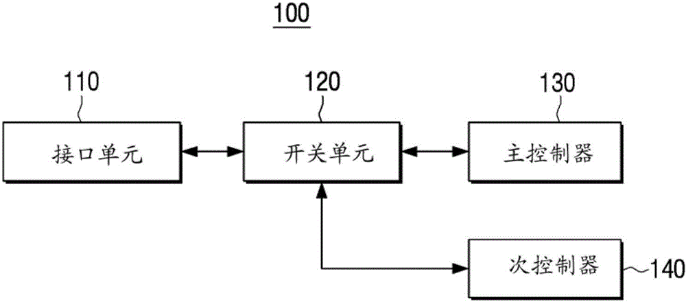
提供一种图像显示装置,包括:接口单元,用于接收图像信号;主控制器,用于在正常模式状态中执行用于处理图像信号的控制操作;次控制器,用于在省电模式状态中执行用于提供低功率服务的控制操作;以及开关单元,用于在正常模式状态中将接口单元连接到主控制器并且在省电模式状态中被切换以接口单元连接到次控制器。
An image display device is provided, comprising: an interface unit for receiving an image signal; a main controller for performing a control operation for processing the image signal in a normal mode state; a sub-controller for performing a control operation in a power saving mode state performing a control operation for providing a low power service; and a switch unit for connecting the interface unit to the main controller in the normal mode state and switched to connect the interface unit to the sub controller in the power saving mode state.
Description
相关申请的交叉引用Cross References to Related Applications
本申请要求2011年7月8日在韩国知识产权局提交的韩国专利申请第10-2011-0068050号的优先权,其全部内容通过引用合并于此。This application claims priority from Korean Patent Application No. 10-2011-0068050 filed in the Korean Intellectual Property Office on Jul. 8, 2011, the entire contents of which are hereby incorporated by reference.
技术领域 technical field
与示范性实施例一致的装置涉及一种图像显示装置和用于控制该图像显示装置的方法,更具体地,涉及一种最小化在省电模式状态中消耗的电力的图像显示装置,以及用于控制该图像显示装置的方法。Devices consistent with the exemplary embodiments relate to an image display device and a method for controlling the image display device, and more particularly, to an image display device that minimizes power consumed in a power saving mode state, and uses A method for controlling the image display device.
背景技术 Background technique
在图像显示装置的快速发展领域,最近已经出现了许多类型的新功能。一种这样的新功能包括减小图像显示装置所消耗的电量的功能。In the rapidly developing field of image display devices, many types of new functions have recently appeared. One such new function includes a function of reducing the power consumed by the image display device.
因为这种功能对有环境意识的消费者来说可能是重要的辨别因素(discriminator),所以省电模式功能的重要性增长了。Because this functionality can be an important discriminator to environmentally conscious consumers, the importance of the power save mode functionality has grown.
在传统的图像显示装置中,当在预定时间内没有感测到构成图像信号的同步信号或时钟信号时,传统的图像显示装置进入省电模式状态。In a conventional image display device, when a synchronization signal or a clock signal constituting an image signal is not sensed for a predetermined time, the conventional image display device enters a power saving mode state.
然而,在传统的图像显示装置情况下,电力仍然施加到在感测同步信号或时钟信号时未使用的一个或多个芯片,并且仍然保持激活状态。因此,即使在省电模式状态中,所耗费的电力的总量也包括由于向在感测同步信号或时钟信号时未使用的芯片提供电力而浪费的相当大的数量。However, in the case of a conventional image display device, power is still applied to one or more chips that are not used when sensing a synchronization signal or a clock signal, and remains activated. Thus, even in the power saving mode state, the total amount of power consumed includes a substantial amount wasted due to powering chips that are not in use when sensing the synchronization signal or the clock signal.
发明内容 Contents of the invention
一个或多个示范性实施例可以克服以上缺点。还可以克服上面未描述的其它缺点。然而,要理解,并非每个示范性实施例都必须克服上面描述的问题中的任何一个。One or more exemplary embodiments may overcome the above disadvantages. Other disadvantages not described above can also be overcome. However, it is to be understood that not every exemplary embodiment has to overcome any of the problems described above.
一个或多个示范性实施例提供一种图像显示装置,该图像显示装置执行用于在正常模式状态中通过主控制器处理图像信号的控制操作以及用于在省电模式状态中通过次控制器(sub-controller)提供低功率服务的控制操作,以及用于控制该图像显示装置的方法。One or more exemplary embodiments provide an image display device that performs a control operation for processing an image signal by a main controller in a normal mode state and for processing an image signal by a sub controller in a power saving mode state. A (sub-controller) provides a control operation of a low power service, and a method for controlling the image display device.
根据示范性实施例的一方面,提供一种图像显示装置。该图像显示装置可以包括:接口单元,用于接收图像信号;主控制器,用于在正常模式状态中执行用于处理图像信号的控制操作;次控制器,用于在省电模式状态中执行用于提供低功率服务的控制操作;以及开关单元,用于在正常模式状态中将接口单元连接到主控制器并且在省电模式被切换为将接口单元连接到次控制器。According to an aspect of the exemplary embodiments, there is provided an image display device. The image display device may include: an interface unit for receiving an image signal; a main controller for performing a control operation for processing the image signal in a normal mode state; a sub-controller for performing a control operation in a power saving mode state a control operation for providing a low power service; and a switch unit for connecting the interface unit to the main controller in the normal mode state and switched to connect the interface unit to the sub controller in the power saving mode.
所述接口单元可以包括用于接收模拟图像信号的模拟输入端口和用于接收数字图像信号的数字输入端口。所述开关单元可以包括布置在模拟输入端口和主控制器之间的第一线路上的第一开关和布置在数字输入端口和主控制器之间的第二线路上的第二开关。The interface unit may include an analog input port for receiving an analog image signal and a digital input port for receiving a digital image signal. The switching unit may include a first switch disposed on a first line between the analog input port and the main controller and a second switch disposed on a second line between the digital input port and the main controller.
所述数字输入端口可以是高清晰度多媒体接口(HDMI)输入端口。所述第二线路可以包括至少一对传输线,其中该传输线之间的差分阻抗已经被调整到预设阈值范围之内。The digital input port may be a High Definition Multimedia Interface (HDMI) input port. The second line may include at least one pair of transmission lines, wherein the differential impedance between the transmission lines has been adjusted to be within a preset threshold range.
所述数字输入端口可以是HDMI输入端口。所述第二线路可以包括至少一对传输线和阻抗补偿器,该阻抗补偿器分别连接到该传输线以将该传输线之间的差分阻抗调整到预设阈值范围之内。The digital input port may be an HDMI input port. The second line may include at least one pair of transmission lines and impedance compensators respectively connected to the transmission lines to adjust the differential impedance between the transmission lines within a preset threshold range.
当在正常模式状态中没有接收到所述图像信号达预设时间时,所述主控制器可以向次控制器发送省电模式改变请求。当次控制器接收到省电模式改变请求时,所述次控制器可以控制开关单元向子控制器提供图像信号,并且可以将主控制器去激活。When the image signal is not received for a preset time in the normal mode state, the main controller may transmit a power saving mode change request to the sub controller. When the sub-controller receives the power saving mode change request, the sub-controller may control the switching unit to provide an image signal to the sub-controller, and may deactivate the main controller.
当在正常模式状态中没有接收到图像信号达预设时间时,所述主控制器可以控制开关单元向次控制器提供图像信号,然后改变为非激活状态。When the image signal is not received for a preset time in the normal mode state, the main controller may control the switch unit to provide the image signal to the sub controller, and then change to an inactive state.
当在省电模式状态中从接口单元接收到图像信号时,所述次控制器可以从省电模式状态改变为正常模式状态以激活主控制器,并且还控制开关单元将接口单元连接到主控制器。When receiving an image signal from the interface unit in the power saving mode state, the secondary controller may change from the power saving mode state to the normal mode state to activate the main controller, and also control the switch unit to connect the interface unit to the main controller device.
所述图像显示装置还可以包括:图像处理器,其包括主控制器并且对于在正常模式状态中输入的图像信号执行图像处理;最小化传输差分信号(TDMS)开关单元,其连接到开关单元并且在正常模式状态中将接口单元的多个数字输入端口中的一个连接到主控制器;以及电力供应单元,其向图像显示单元供电,其中,当正常模式状态改变为省电模式状态时,所述次控制器控制电力供应单元中断提供给主控制器、图像处理器和TDMS开关单元中的至少一个的电力。The image display device may further include: an image processor including a main controller and performing image processing on an image signal input in a normal mode state; a transmission minimized differential signal (TDMS) switching unit connected to the switching unit and One of the plurality of digital input ports of the interface unit is connected to the main controller in the normal mode state; and a power supply unit that supplies power to the image display unit, wherein when the normal mode state is changed to the power saving mode state, the The sub-controller controls the power supply unit to interrupt power supplied to at least one of the main controller, the image processor, and the TDMS switching unit.
当在正常模式状态中从接口单元接收到图像信号时,所述次控制器可以控制电力供应单元向主控制器、图像处理器和TDMS开关单元供电。The sub-controller may control the power supply unit to supply power to the main controller, the image processor, and the TDMS switching unit when an image signal is received from the interface unit in a normal mode state.
所述低功率服务可以包括中断提供给图像显示装置的电力和/或改变图像显示装置的外部输入源。The low power service may include interrupting power supplied to the image display device and/or changing an external input source of the image display device.
根据另一示范性实施例的一方面,提供一种用于控制图像显示装置的方法,该图像显示装置包括用于接收图像信号的接口单元、用于在正常模式状态中执行用于处理图像信号的控制操作的主控制器、以及用于在省电模式状态中执行用于提供低功率服务的控制操作的次控制器。所述方法可以包括:在正常模式状态中将接口单元连接到主控制器;以及当正常模式状态改变为省电模式状态时,将接口单元连接到次控制器。According to an aspect of another exemplary embodiment, there is provided a method for controlling an image display device including an interface unit for receiving an image signal, for performing a process for processing the image signal in a normal mode state. A main controller for controlling operations, and a sub-controller for performing control operations for providing low power services in a power saving mode state. The method may include: connecting the interface unit to the main controller in the normal mode state; and connecting the interface unit to the sub-controller when the normal mode state is changed to the power saving mode state.
所述接口单元可以包括用于接收模拟图像信号的模拟输入端口和用于接收数字图像信号的数字输入端口。所述开关单元可以包括布置在模拟输入端口和主控制器之间的第一线路上的第一开关和布置在数字输入端口和主控制器之间的第二线路上的第二开关。The interface unit may include an analog input port for receiving an analog image signal and a digital input port for receiving a digital image signal. The switching unit may include a first switch disposed on a first line between the analog input port and the main controller and a second switch disposed on a second line between the digital input port and the main controller.
所述数字输入端口可以是HDMI输入端口。所述第二线路可以包括至少一对传输线,其中该传输线之间的差分阻抗已经被调整到在预设阈值范围之内。The digital input port may be an HDMI input port. The second line may include at least one pair of transmission lines, wherein the differential impedance between the transmission lines has been adjusted to be within a preset threshold range.
所述数字输入端口可以是HDMI输入端口。所述第二线路可以包括至少一对传输线和阻抗补偿器,该阻抗补偿器分别连接到该传输线以将该传输线的差分阻抗调整到预设阈值范围之内。The digital input port may be an HDMI input port. The second circuit may include at least one pair of transmission lines and impedance compensators respectively connected to the transmission lines to adjust the differential impedance of the transmission lines within a preset threshold range.
所述方法还可以包括:当在正常模式状态中没有接收到图像信号达预设时间时,从主控制器向次控制器发送省电模式改变请求;以及当次控制器接收到省电模式改变请求时,通过次控制器控制开关单元向次控制器提供图像信号,并且将主控制器去激活。The method may further include: when the image signal is not received for a preset time in the normal mode state, transmitting a power saving mode change request from the main controller to the sub-controller; and when the sub-controller receives the power saving mode change When requested, the sub-controller controls the switch unit to provide an image signal to the sub-controller, and deactivates the main controller.
所述方法还可以包括:当在正常模式状态中没有接收到图像信号达预设时间时,利用主控制器控制开关单元向次控制器提供图像信号,然后将主控制器改变为非激活状态。The method may further include: when the image signal is not received for a preset time in the normal mode state, controlling the switching unit to supply the image signal to the sub controller using the main controller, and then changing the main controller to an inactive state.
所述方法还可以包括:当在省电模式状态中从接口单元接收到图像信号时,将次控制器从省电模式状态改变为正常模式状态以激活主控制器,并且控制开关单元将图像信号从接口单元提供给主控制器。The method may further include: when receiving the image signal from the interface unit in the power saving mode state, changing the sub controller from the power saving mode state to the normal mode state to activate the main controller, and controlling the switch unit to convert the image signal Provided from the interface unit to the master controller.
所述图像显示装置还可以包括:图像处理器,其包括主控制器并对于在正常模式状态中输入的图像信号执行图像处理;TDMS开关单元,其连接到开关单元并且在正常模式状态中将接口单元的多个数字输入端口中的一个连接到主控制器;以及电力供应单元,其向图像显示装置供电,其中该方法还包括:当正常模式状态改变为省电模式状态时,通过次控制器控制电力供应单元中断提供给主控制器、图像处理器和TDMS开关单元中的至少一个的电力。The image display device may further include: an image processor including a main controller and performing image processing on an input image signal in a normal mode state; a TDMS switch unit connected to the switch unit and connecting the interface One of the plurality of digital input ports of the unit is connected to the main controller; and a power supply unit that supplies power to the image display device, wherein the method further includes: when the normal mode state is changed to the power saving mode state, by the secondary controller The control power supply unit interrupts power supplied to at least one of the main controller, the image processor, and the TDMS switching unit.
所述方法还可以包括:当在省电模式状态中从接口单元接收到图像信号时,通过次控制器控制电力供应单元向主控制器、图像处理器和TDMS开关单元提供电力。The method may further include, when the image signal is received from the interface unit in the power saving mode state, controlling the power supply unit to supply power to the main controller, the image processor, and the TDMS switching unit through the sub controller.
所述低功率服务可以包括中断提供给图像显示装置的电力和/或改变图像显示装置的外部输入源。The low power service may include interrupting power supplied to the image display device and/or changing an external input source of the image display device.
如上所述,根据示范性实施例,可以中断提供给主控制器、TDMS开关单元和图像处理器的电力。此外,可以通过仅使用次控制器执行用于提供低功率服务的控制操作。因此,可以最小化图像显示装置在省电模式状态中所消耗的电力。As described above, according to an exemplary embodiment, power supplied to the main controller, the TDMS switching unit, and the image processor may be interrupted. Also, a control operation for providing a low power service can be performed by using only the secondary controller. Therefore, the power consumed by the image display device in the power saving mode state can be minimized.
示范性实施例的附加方面和优点将在详细描述中阐述,将从所述详细描述中变得清楚,或者通过实践示范性实施例而习得。Additional aspects and advantages of the exemplary embodiments will be set forth in the detailed description, will become apparent from the detailed description, or will be learned by practicing the exemplary embodiments.
附图说明 Description of drawings
在附图中:In the attached picture:
图1是示出根据示范性实施例的图像显示装置的结构的框图;FIG. 1 is a block diagram illustrating a structure of an image display device according to an exemplary embodiment;
图2是示出根据示范性实施例的图像显示装置的具体结构的框图;FIG. 2 is a block diagram illustrating a detailed structure of an image display device according to an exemplary embodiment;
图3A和图3B是示出根据示范性实施例的图像显示装置的一些元件的电路图;以及3A and 3B are circuit diagrams illustrating some elements of an image display device according to an exemplary embodiment; and
图4是示出根据示范性实施例的用于控制图像显示装置的方法的流程图。FIG. 4 is a flowchart illustrating a method for controlling an image display device according to an exemplary embodiment.
具体实施方式Detailed ways
在下文中,将参考附图描述各种示范性实施例。Hereinafter, various exemplary embodiments will be described with reference to the accompanying drawings.
在下面的描述中,相同的参考标号用于相同的元件。给出以下所论及的各种细节以帮助提供对示范性实施例的全面理解。因而,将认识到示范性实施例可以在没有这种细节的情况下执行。此外,没有详细描述熟悉本领域的人已知的功能或元件,因为它们可能以不必要的细节模糊示范性实施例的教导。In the following description, the same reference numerals are used for the same elements. Various details discussed below are given to help provide a thorough understanding of the exemplary embodiments. Accordingly, it will be appreciated that the exemplary embodiments may be practiced without such details. Also, functions or elements that are known to those skilled in the art are not described in detail since they might obscure the teachings of the exemplary embodiments with unnecessary detail.
图1是示出根据示范性实施例的图像显示装置100的结构的框图。参照图1,图像显示装置100包括接口单元110、开关单元120、主控制器130和次控制器140。FIG. 1 is a block diagram illustrating a structure of an
接口单元110接收图像信号。接口单元110包括用于接收模拟图像信号的模拟输入端口。接口单元110还包括用于接收数字图像信号的数字输入端口。从而,接口单元110可以作为从外部设备接收图像信号和音频信号的输入源来操作。The
开关单元120在正常模式状态中将接口单元110连接到主控制器130。当处于省电模式状态中时,开关单元120将接口单元110连接到次控制器140。The
主控制器130在正常模式状态中执行用于处理图像信号的控制操作。此处,正常模式状态是指基于经由图像显示装置100输入的图像信号来显示图像的普通模式。The
因此,主控制器130一般控制图像显示装置100的各个元件。更详细地,主控制器130可以控制图像处理器(未示出)对于通过接口单元110接收的图像信号和音频信号执行信号处理,诸如视频解码、视频缩放、音频解码等等。此外,主控制器130可以控制显示单元(未示出)和音频输出单元(未示出)输出经处理的图像和音频信号。Accordingly, the
在此示范性实施例中,当在正常模式状态中在预设时间内没有接收到图像信号时,正常模式状态改变为省电模式状态。In this exemplary embodiment, when an image signal is not received for a preset time in the normal mode state, the normal mode state is changed to the power saving mode state.
省电模式状态是指显示电力管理设置模式(display power managementsetup mode,DPMS)并且中断施加到图像显示装置100的元件的电力。中断施加到这些元件的电力的目的是避免不必要的电力消耗,并且当在预定时间内没有图像信号输入时适合执行这种能量的节约。The power saving mode state refers to display power management setup mode (DPMS) and interruption of power applied to elements of the
为了这个目的,当在预设时间量内没有接收到图像信号时,主控制器130向次控制器140发送省电模式改变请求。可替换地,主控制器130可以控制开关单元120向次控制器140提供图像信号并且随后改变为非激活(inactive)状态。For this purpose, when an image signal is not received for a preset amount of time, the
当次控制器140接收到来自主控制器130的省电模式改变请求时,次控制器140控制开关单元120向次控制器140提供图像信号,并且也将主控制器130去激活。When the sub-controller 140 receives a power saving mode change request from the
在这种情况下,次控制器140可以中断提供给包括主控制器130、最小化传输差分信号(TDMS)开关单元(未示出)、图像处理器(未示出)和显示单元的各种元件的电力。此处,TDMS开关单元是连接到开关单元120的单元,并且向主控制器130发送通过多个数字输入端口输入的数字图像信号中的一个。此外,图像处理器对于输入图像信号执行图像处理,并且显示单元显示经信号处理的图像信号。In this case, the sub-controller 140 may interrupt the power supplied to various components including the
当处于省电模式状态中时,次控制器140也可以执行用于提供低功率服务的控制操作。此处,低功率服务的概念是指响应于当图像显示装置100处于省电模式状态中时输入的用户命令的最少的(minimum)反馈操作。例如,低功率服务可以包括中断图像显示装置100的电力。低功率服务的另一示例包括改变图像显示装置100的外部输入源。When in the power saving mode state, the sub-controller 140 may also perform a control operation for providing a low power service. Here, the concept of low power service refers to a minimum feedback operation in response to a user command input when the
当从接口单元110接收到图像信号,并且图像显示装置100处于省电模式状态中时,次控制器140将省电模式状态改变为正常模式状态以便激活主控制器130并且控制开关单元120将接口单元110与主控制器130连接。When an image signal is received from the
在这种情况下,次控制器140可以进行控制使得电力被再次提供给主控制器130、TDMS开关单元、图像处理器和显示单元。In this case, the sub-controller 140 may control such that power is supplied to the
如上所述,根据示范性实施例,在省电模式状态中,中断先前提供给主控制器130、TDMS开关单元、图像处理器和显示单元的电力。此外,次控制器140执行用于提供低功率服务的控制操作。因此,在省电模式状态中图像显示装置100所消耗的电力可以被最小化(例如,将低于或等于1W)。As described above, according to an exemplary embodiment, in the power saving mode state, power previously supplied to the
如上所述,接口单元110可以包括模拟输入端口和数字输入端口。As mentioned above, the
因此,开关单元120可以包括布置在模拟输入端口和主控制器130之间的第一线路上的第一开关(未示出)、以及布置在数字输入端口和主控制器130之间的第二线路上的第二开关(未示出)。Therefore, the
在这种情况下,如果数字输入端口是高清晰度多媒体接口(HDMI)输入端口,则HDMI输入端口和主控制器130之间的第二线路可以包括至少一对传输线,其中每对的传输线之间的差分阻抗已经调整到预设阈值范围之内。In this case, if the digital input port is a high-definition multimedia interface (HDMI) input port, the second line between the HDMI input port and the
如果数字输入端口是HDMI输入端口,则HDMI输入端口和主控制器130之间的第二线路可以包括至少一对传输线和阻抗补偿器,该阻抗补偿器分别连接到该传输线以将每对传输线之间的差分阻抗调整到预设阈值范围之内。If the digital input port is an HDMI input port, the second line between the HDMI input port and the
将参照图3A和图3B对此进行更详细地描述。This will be described in more detail with reference to FIGS. 3A and 3B .
图2是示出根据示范性实施例的图像显示装置100的详细结构的框图。参照图2,图像显示装置100包括接口单元110、开关单元120、主控制器130、图像处理器135、次控制器140、TDMS开关单元150、显示单元160和电力供应单元170。FIG. 2 is a block diagram illustrating a detailed structure of the
接口单元110将图像显示装置100连接到外部设备。更详细地,接口单元110包括连接到至少一个外部设备的至少一个输入端口,以作为从外部设备接收图像信号和音频信号的输入源来操作。The
如图2所示,在示范性实施例中,接口单元110包括用于接收模拟图像信号的D-Sub输入端口111,以及用于接收数字图像信号的HDMI输入端口113和数字视频接口(DVI)输入端口115。As shown in FIG. 2, in an exemplary embodiment, the
更详细地,D-Sub输入端口111从外部设备接收模拟红(R)、绿(G)和蓝(B)图像信号以及水平/垂直(H/V)同步信号。HDMI输入端口113和DVI输入端口115接收数字R、G和B图像信号以及时钟信号Tx0±、Tx1±、Tx2±和TcX±。In more detail, the D-
在此示范性实施例中,接口单元110包括D-Sub输入端口111、HDMI输入端口113和DVI输入端口115。然而,这仅是示例;接口单元110还可以包括其它类型的输入端口。In this exemplary embodiment, the
例如,接口单元110还可以包括S-Video输入端口、分量(component)输入、复合(composite)输入等等。For example, the
当该图像显示装置100处于正常模式状态中时,开关单元120将接口单元110连接到主控制器130。当处于省电模式状态中时,开关单元120被切换以便将接口单元110连接到次控制器140。When the
根据此示范性实施例,开关单元120包括第一开关121、第二开关123和第三开关125。According to this exemplary embodiment, the
此处,第一开关121布置在模拟输入端口和主控制器130之间的第一线路上,而第二开关123布置在数字输入端口和主控制器130之间的第二线路上。此外,第三开关125布置在数字输入端口和主控制器130之间的第三线路上。Here, the
因此,在正常模式状态中,第一开关121将D-Sub输入端口111连接到主控制器130,并且第二开关123通过TDMS开关单元150将HDMI输入端口113连接到主控制器130。此外,在正常模式状态中,第三开关125通过TDMS开关单元150将DVI输入端口115连接到主控制器130。Therefore, in the normal mode state, the
在省电模式状态中,第一开关121、第二开关123和第三开关125分别将D-Sub输入端口111、HDMI输入端口113和DVI输入端口115连接到次控制器140。In the power saving mode state, the
因此,当图像显示装置100处于正常模式状态中时输入图像信号可以被发送到主控制器130,而当图像显示装置100处于省电模式状态中时输入图像信号可以被发送到次控制器140。Accordingly, the input image signal may be sent to the
可以由主控制器130或次控制器140控制以上描述的开关单元120的操作。The operation of the
在此示范性实施例中,第一开关单元120包括第一开关121、第二开关123和第三开关125。然而,这仅是示例。因此,如果接口单元110还包括另一类型的输入端口,则开关单元120还可以包括连接到对应的输入端口的开关。即使在这种情况下,对应的输入端口也可以取决于图像显示装置100是处于正常模式状态还是处于省电模式状态,来连接到主控制器130或次控制器140。In this exemplary embodiment, the
TDMS开关单元150连接到开关单元120并且在正常模式状态中将接口单元110的多个数字输入端口中的一个连接到主控制器130。The
更详细地,TDMS开关单元150在正常模式状态中可以向主控制器130发送下述图像信号中的一个:通过第二开关123输入的HDMI格式的图像信号、以及通过第三开关125输入的DVI格式的图像信号。因此,TDMS开关单元150可以包括用于选择并输出多个输入数字图像信号中的一个的复用器(MUX)(未示出)。In more detail, the
主控制器130控制图像显示装置100的元件的总体操作。具体地,主控制器130可以实现为微型计算机(Micom)、中央处理单元(CPU)、机器控制单元(MCU)等等,以控制图像显示装置100的元件在显示单元160的屏幕上显示在正常模式状态中输入的图像信号。The
更详细地,主控制器130可以控制图像处理器135对于通过接口单元110输入的图像和音频信号执行诸如视频解码、视频缩放、音频解码等等之类的信号处理,并且控制显示单元160和音频输出单元(未示出)分别输出经信号处理的图像信号和音频信号。In more detail, the
可以将执行以上描述的功能的主控制器130包括为图像处理器135的一部分。The
图像处理器135可以包括主控制器130以在主控制器130的控制之下对于在正常模式状态中输入的图像信号执行图像处理。The
更详细地,当图像显示装置100处于正常模式状态中时,图像处理器135可以根据显示单元160的标准处理通过第一开关121输入的D-Sub格式的图像信号、通过TDMS开关单元150输入的HDMI格式的图像信号或者DVI格式的图像信号。In more detail, when the
为了这个目的,图像处理器135可以包括解码器(未示出)和缩放器(scaler)(未示出)。在这种情形下,解码器解码在正常模式状态中输入的图像信号,并且缩放器根据显示单元160的输出标准来调整垂直频率、分辨率和画面宽高比(picture ratio)。因此,图像处理器135可以将图像信号转换成为可以通过显示单元160的屏幕输出的信号。For this purpose, the
当在正常模式状态中在预设时间内没有接收到图像信号时,主控制器130从正常模式状态改变为省电模式状态。换句话说,当在预设时间内通过根据用户命令选择的输入端口没有接收到图像信号时,主控制器130控制图像显示装置100从正常模式状态改变到省电模式状态。When an image signal is not received for a preset time in the normal mode state, the
更详细地,当图像显示装置100处于正常模式状态中时,主控制器130可以监视在预设时间内通过由用户选择的输入端口是否接收到同步信号(即,水平同步信号或者垂直同步信号)或者时钟信号。此外,当在预设时间内没有接收到同步信号或时钟信号时,主控制器130可以产生用于省电模式改变请求的控制信号并且向次控制器140发送该控制信号。In more detail, when the
当次控制器140接收到来自主控制器130的省电模式改变请求时,次控制器140控制开关单元120将接口单元110连接到次控制器140,并且中断正被提供给图像显示装置100的元件的电力。When the sub-controller 140 receives a power saving mode change request from the
更详细地,当次控制器140接收到省电模式改变请求时,次控制器140可以控制电力供应单元170中断提供给主控制器130、图像处理器140、TDMS开关单元150和显示单元160的电力。In more detail, when the sub-controller 140 receives a power saving mode change request, the sub-controller 140 may control the
次控制器140在省电模式状态中还可以执行用于提供低功率服务的控制操作。此处,低功率服务是对于在省电模式中输入的用户命令的最少的反馈操作(即,可以指图像显示装置100的电力中断、图像显示装置100的外部输入源改变等等)。The sub-controller 140 may also perform a control operation for providing a low power service in the power saving mode state. Here, the low power service is a minimal feedback operation for a user command input in the power saving mode (ie, may refer to power interruption of the
例如,当次控制器140在省电模式状态中从用户接收到用于中断图像显示装置100的电力的命令时,次控制器140可以进行控制以中断提供给图像显示装置100的全部元件的电力,从而中断图像显示装置100的电力。For example, when the sub-controller 140 receives a command for interrupting the power of the
作为另一示例,当次控制器140在省电模式状态中从用户接收用于改变输入源的命令时,次控制器14可以进行控制以选择相应的输入源。As another example, when the sub-controller 140 receives a command for changing an input source from a user in the power saving mode state, the sub-controller 14 may control to select a corresponding input source.
为了这个目的,次控制器140可以在省电模式状态中控制电力供应单元170向接收用户命令的输入单元(未示出)提供电力。For this purpose, the sub-controller 140 may control the
此外,当次控制器140在省电模式状态中从接口单元110接收到图像信号时,次控制器140从省电模式状态改变为正常模式状态。Also, when the sub-controller 140 receives an image signal from the
如上所述,开关单元120在省电模式状态中在次控制器140的控制之下将接口单元110连接到次控制器140。因此,次控制器140可以在省电模式状态中监视是否通过由用户选择的输入端口接收到同步信号(水平同步信号和垂直同步信号中的至少一个)或时钟信号。As described above, the
当根据监视结果在省电模式状态中接收到同步信号或时钟信号时,次控制器140可以控制电力供应单元170再次向主控制器130、图像处理器135、TDMS开关单元150和显示单元160提供电力。When a synchronization signal or a clock signal is received in the power saving mode state according to the monitoring result, the
次控制器140控制开关单元120将接口单元110连接到主控制器130,以便向主控制器130发送通过由用户选择的输入端口输入的图像信号。The sub-controller 140 controls the
因此,从用户选择的输入端口再次输入的图像信号可以由图像处理器130来处理并且被显示在显示单元160的屏幕上。Accordingly, an image signal input again from the input port selected by the user may be processed by the
执行以上描述的功能的次控制器140可以实现为Micom、CPU、MCU等等。The sub-controller 140 performing the functions described above may be implemented as a Micom, CPU, MCU, or the like.
次控制器140可以包括模数转换器(ADC)以检测接收到的同步信号或时钟信号。换句话说,次控制器140可以将在省电模式中接收到的同步信号或时钟信号转换为数字信号并且基于该数字信号确定在省电模式状态中是否接收到同步信号或时钟信号。The sub-controller 140 may include an analog-to-digital converter (ADC) to detect a received sync signal or clock signal. In other words, the sub-controller 140 may convert the synchronization signal or the clock signal received in the power saving mode into a digital signal and determine whether the synchronization signal or the clock signal is received in the power saving mode state based on the digital signal.
作为另一示例,假定在省电模式中从用户输入用于改变输入源的命令,并且通过输入端口从改变的输入源输入图像信号。As another example, assume that a command for changing an input source is input from a user in the power saving mode, and an image signal is input from the changed input source through an input port.
在这种情况下,在省电模式状态中从改变的输入源输入的图像信号通过开关单元120输入到次控制器140中。In this case, an image signal input from a changed input source in the power saving mode state is input into the sub-controller 140 through the
因此,次控制器140控制电力供应单元170再次向主控制器130、图像处理器135、TDMS开关单元150和显示单元160供电。此外,次控制器140控制开关单元120将接口单元110连接到主控制器130,以便向主控制器130发送通过改变的输入源输入的图像信号。Accordingly, the sub-controller 140 controls the
在以上描述的示范性实施例中,当在预设时间内通过用户选择的输入端口没有接收到图像信号时,主控制器130向次控制器140发送省电模式改变请求。此外,次控制器140根据省电模式改变请求控制开关单元120的开关操作并且控制电力供应单元170中断提供给主控制器130的电力。In the above-described exemplary embodiments, when an image signal is not received through a user-selected input port for a preset time, the
然而,这仅是示例,从而主控制器130可以控制开关单元120和电力供应单元170。更详细地,当在预设时间内通过用户选择的输入端口没有接收到图像信号时,主控制器130可以控制开关单元120将接口单元110连接到次控制器140并且控制电力供应单元170中断提供的电力。However, this is just an example, so the
此外,在上面描述的示范性实施例中,主控制器130包括在图像处理器135中,但是这仅是示例。因此,主控制器130可以从图像处理器135分开地安装。Also, in the above-described exemplary embodiments, the
显示单元160显示从图像处理器135输入的图像信号。显示单元160可以如在一般显示装置中那样被实现为液晶显示(LCD)面板,并且可以包括诸如面板驱动器(未示出)、显示面板(未示出)、背光驱动器(未示出)、背光发射器(未示出)等等之类的详细结构。The
在这种情况下,因为次控制器140在省电模式状态中中断提供给显示单元160的电力,所以电力不提供给面板驱动器、显示面板、背光驱动器和背光发射器。In this case, since the sub-controller 140 interrupts the power supplied to the
电力供应单元170向图像显示装置100供电。电力供应单元170的电力状态在正常模式状态中可以由主控制器130控制,而在省电模式状态中可以由次控制器140控制。The
根据预设的示范性实施例的图像显示装置100还可以包括存储单元(storage unit)(未示出),该存储单元存储操作图像显示装置100所需的各种类型的程序并且可以实现为存储器(memory)、硬盘驱动器(HDD)等等。The
图3A和图3B是示出根据示范性实施例的图像显示装置100的一些元件的电路图。更详细地,图3A和图3B是示出HDMI输入端口113、第二开关123和主控制器130之间的连接关系的电路图。为了描述方便,将省略TDMS开关单元150。3A and 3B are circuit diagrams illustrating some elements of the
通常,HDMI连接端口和HDMI接收器通过四对传输线彼此连接。此处,三对传输线用于传送数据,而一对传输线用于传送时钟信号。Generally, an HDMI connection port and an HDMI receiver are connected to each other through four pairs of transmission lines. Here, three pairs of transmission lines are used to transmit data, and one pair of transmission lines is used to transmit clock signals.
在这种情况下,连接在HDMI连接端口和HDMI接收器之间的四对传输线中的每对传输线之间的差分阻抗必须符合HDMI符合性(compliance)测试规范——测试ID5-8中定义的标准。In this case, the differential impedance between each of the four pairs of transmission lines connected between the HDMI connection port and the HDMI receiver must comply with the HDMI compliance test specification - as defined in Test ID5-8 standard.
更详细地,根据HDMI符合性测试规范——测试ID5-8,连接HDMI连接端口和HDMI接收器的四对传输线中的每对传输线之间的差分阻抗将被包括在85Ω和115Ω之间的范围之内,从而符合该标准。In more detail, according to the HDMI Compliance Test Specification - Test ID5-8, the differential impedance between each of the four pairs of transmission lines connecting the HDMI connection port and the HDMI receiver will be included in the range between 85Ω and 115Ω within, thereby complying with the standard.
可以如下面的等式1中那样计算一对传输线之间的差分阻抗:The differential impedance between a pair of transmission lines can be calculated as in Equation 1 below:
其中Zdiff表示差分阻抗,Z0表示每条传输线的阻抗,S表示每对传输线之间的距离(space),并且H表示从接地层到传输线的高度。where Z diff represents the differential impedance, Z 0 represents the impedance of each transmission line, S represents the distance (space) between each pair of transmission lines, and H represents the height from the ground plane to the transmission line.
在参考图1和图2描述的根据示范性实施例的图像显示装置100中,第二开关123连接在HDMI输入端口113和主控制器130之间。In the
此处,第二开关123可以实现为诸如电容器、电阻器等等的无源元件,因此,由于第二开关123的存在,连接HDMI输入端口113和主控制器130的每对传输线之间的差分阻抗可能改变为偏离了HDMI符合性测试规范——测试ID5-8中定义的标准。Here, the
因此,为了解决这个问题,可以通过使用具有低电容的电容器和具有低电阻值的电阻器来构成第二开关123。可替换地,阻抗补偿器可以连接到HDMI输入端口113和主控制器130之间的传输线以补偿改变了的差分阻抗。Therefore, in order to solve this problem, the
更详细地,如图3A所示,可以使用包括具有低电容的电容器和具有低电阻值的电阻器的第二开关123,以使得连接HDMI输入端口113和主控制器130的每对传输线之间的差分阻抗在90Ω和110Ω之间的范围之内。In more detail, as shown in FIG. 3A, a
更详细地,可以设计第二开关123以便使用具有0.5pF或更小的电容的电容器和具有5Ω或更小的电阻值的电阻器。In more detail, the
此外,如图3B所示,阻抗补偿器180连接到HDMI输入端口113和主控制器130之间的每对传输线,以补偿被第二开关123改变的差分阻抗。In addition, as shown in FIG. 3B , an
更详细地,如果差分阻抗被第二开关123减小,则包括电阻器的阻抗补偿器180可以连接到每对传输线以补偿降低的差分阻抗。如果差分阻抗被第二开关123增加,则包括电容器的阻抗补偿器180可以连接到每对传输线以补偿增加的差分阻抗。In more detail, if the differential impedance is reduced by the
在这种情况下,可以设置阻抗补偿器180的电容器的电容和电阻器的阻抗值,使得被第二开关123改变了的差分阻抗在90Ω和110Ω之间的范围之内。In this case, the capacitance of the capacitor and the impedance of the resistor of the
根据另一方法,可以调整连接HDMI输入端口113和主控制器130的每对传输线的宽度。According to another method, the width of each pair of transmission lines connecting the
换句话说,如在等式1中那样,可以根据传输线的宽度调整差分阻抗。因此,如果差分阻抗由于第二开关123的引入而减小,则连接HDMI输入端口113和主控制器130的每对传输线的宽度可以变窄。如果差分阻抗由于第二开关123的引入而增加,则连接HDMI输入端口113和主控制器130的每对传输线的宽度可以加宽。In other words, as in Equation 1, the differential impedance can be adjusted according to the width of the transmission line. Therefore, if the differential impedance is reduced due to the introduction of the
即使在这种情况下,也可以调整每对传输线的宽度,使得被第二开关123改变了的差分阻抗在90Ω和110Ω之间的范围之内。Even in this case, the width of each pair of transmission lines can be adjusted so that the differential impedance changed by the
在上面描述的示范性实施例中,为了保证一些裕度(some margin)并满足标准范围,可以调整差分阻抗,使其在90Ω和110Ω之间的范围之内。In the exemplary embodiments described above, in order to ensure some margin and meet the standard range, the differential impedance can be adjusted to be in the range between 90Ω and 110Ω.
图4是示出根据示范性实施例的用于控制图像显示装置的方法的流程图。FIG. 4 is a flowchart illustrating a method for controlling an image display device according to an exemplary embodiment.
根据此示范性实施例的图像显示装置包括:接口单元,用于接收图像信号;主控制器,用于在正常模式状态中执行用于处理图像信号的控制操作;以及次控制器,在省电模式状态中执行用于提供低功率服务的控制操作。The image display device according to this exemplary embodiment includes: an interface unit for receiving an image signal; a main controller for performing a control operation for processing the image signal in a normal mode state; and a sub-controller for power saving A control operation for providing a low power service is performed in the mode state.
因此,在操作S410中,接口单元在正常模式状态中连接到主控制器。Accordingly, the interface unit is connected to the main controller in a normal mode state in operation S410.
在操作S420中,当正常模式状态被改变为省电模式状态时,接口单元连接到次控制器。In operation S420, when the normal mode state is changed to the power saving mode state, the interface unit is connected to the sub-controller.
此处,图像显示装置的接口单元可以包括接收模拟图像信号的模拟输入端口和接收数字图像信号的数字输入端口。开关单元可以包括布置在模拟输入端口和主控制器之间的第一线路上的第一开关,以及布置在数字输入端口和主控制器之间的第二线路上的第二开关。Here, the interface unit of the image display device may include an analog input port receiving an analog image signal and a digital input port receiving a digital image signal. The switch unit may include a first switch disposed on a first line between the analog input port and the main controller, and a second switch disposed on a second line between the digital input port and the main controller.
在这种情况下,数字输入端口可以是HDMI输入端口,并且第二线路可以包括至少一对传输线,其中至少一对传输线之间的差分阻抗已经被调整到预设阈值范围之内。In this case, the digital input port may be an HDMI input port, and the second line may include at least one pair of transmission lines, wherein the differential impedance between the at least one pair of transmission lines has been adjusted within a preset threshold range.
数字输入端口可以是HDMI输入端口,并且第二线路可以包括至少一对传输线和阻抗补偿器,该阻抗补偿器分别连接到传输线以将传输线之间的差分阻抗调整到预设阈值范围之内。The digital input port may be an HDMI input port, and the second line may include at least one pair of transmission lines and impedance compensators respectively connected to the transmission lines to adjust a differential impedance between the transmission lines within a preset threshold range.
所述方法还可以包括:当在正常模式状态中在预设时间内没有接收到图像信号时,从主控制器向次控制器发送省电模式改变请求;以及当接收到省电模式改变请求时,通过次控制器控制开关单元以向次控制器提供图像信号并且使主控制器去激活。The method may further include: when the image signal is not received for a preset time in the normal mode state, transmitting a power saving mode change request from the main controller to the sub controller; and when the power saving mode change request is received , the switching unit is controlled by the sub-controller to supply the image signal to the sub-controller and deactivate the main controller.
所述方法还可以包括:当在正常模式状态中在预设时间内没有接收到图像信号时,通过主控制器控制开关单元以向次控制器提供图像信号并将主控制器改变为非激活状态。The method may further include: when the image signal is not received for a preset time in the normal mode state, controlling the switching unit by the main controller to supply the image signal to the sub controller and changing the main controller to an inactive state .
所述方法还可以包括:当在省电模式状态中从接口单元接收到图像信号时,将次控制器改变为正常模式状态以激活主控制器并且控制开关单元连接接口单元和主控制器。The method may further include, when the image signal is received from the interface unit in the power saving mode state, changing the sub controller to a normal mode state to activate the main controller and controlling the switch unit to connect the interface unit and the main controller.
图像显示装置还可以包括:图像处理器,其包括主控制器并对于在正常模式状态中输入的图像信号执行图像处理;TDMS开关单元,其在正常模式状态中连接到开关单元以将接口单元的多个数字输入端口中的一个连接到主控制器;以及电力供应单元,其向图像显示装置提供电力。The image display device may further include: an image processor including a main controller and performing image processing on an image signal input in the normal mode state; a TDMS switch unit connected to the switch unit in the normal mode state to connect the interface unit One of the plurality of digital input ports is connected to the main controller; and a power supply unit that supplies power to the image display device.
所述方法还可以包括:当正常模式状态改变为省电模式状态时,通过次控制器控制电力供应单元中断提供给主控制器、图像处理器和TDMS开关单元中的至少一个的电力。The method may further include: controlling the power supply unit to interrupt power supplied to at least one of the main controller, the image processor, and the TDMS switching unit by the sub controller when the normal mode state is changed to the power saving mode state.
在这种情况下,所述方法还可以包括:当在省电模式状态中从接口单元接收到图像信号时,通过次控制器控制电力供应单元向主控制器、图像处理器和TDMS开关单元提供电力。In this case, the method may further include: when the image signal is received from the interface unit in the power saving mode state, controlling the power supply unit to supply the main controller, the image processor, and the TDMS switch unit through the secondary controller. electricity.
在该方法中,低功率服务可以包括图像显示装置的电力中断和图像显示装置的外部输入源改变中的至少一个。In the method, the low power service may include at least one of interruption of power of the image display device and change of an external input source of the image display device.
可以通过根据示范性实施例的图像显示装置或未包括给出的图像显示装置的全部元件的另一图像显示装置实现以上描述的方法。The above-described methods may be implemented by the image display device according to the exemplary embodiments or another image display device that does not include all elements of the given image display device.
存储用于执行控制图像显示装置的方法的程序的计算机可读记录介质可以包括存储可以由计算机系统读取的数据的各种类型的物理记录设备。计算机可读记录介质的示例包括ROM、RAM、CD-ROM、磁带、软盘和光学数据存储设备等。计算机可读记录介质也可以被分布在网络耦合的计算机系统之上以使得计算机可读代码以分布的方式被存储和执行。A computer-readable recording medium storing a program for executing a method of controlling an image display apparatus may include various types of physical recording devices storing data readable by a computer system. Examples of the computer-readable recording medium include ROM, RAM, CD-ROM, magnetic tape, floppy disk, and optical data storage devices, among others. The computer readable recording medium can also be distributed over network coupled computer systems so that the computer readable code is stored and executed in a distributed fashion.
前述示范性实施例和优点仅仅是示范性的,并且不应被理解为限制本发明的构思。示范性实施例可以容易地应用于其它类型的装置。此外,对示范性实施例的描述意欲说明而不是限制权利要求的范围,并且许多替换、修改和变化将对本领域技术人员是显而易见的。The foregoing exemplary embodiments and advantages are merely exemplary and should not be construed as limiting the inventive concept. Exemplary embodiments can be readily applied to other types of devices. Furthermore, the description of the exemplary embodiments is intended to illustrate rather than limit the scope of the claims, and many alternatives, modifications, and variations will be apparent to those skilled in the art.
Claims (15)
Applications Claiming Priority (2)
| Application Number | Priority Date | Filing Date | Title |
|---|---|---|---|
| KR10-2011-0068050 | 2011-07-08 | ||
| KR1020110068050A KR20130006167A (en) | 2011-07-08 | 2011-07-08 | Image display apparatus and method for controlling the image display apparatus |
Publications (1)
| Publication Number | Publication Date |
|---|---|
| CN102867501A true CN102867501A (en) | 2013-01-09 |
Family
ID=46025368
Family Applications (1)
| Application Number | Title | Priority Date | Filing Date |
|---|---|---|---|
| CN2012102346931A Pending CN102867501A (en) | 2011-07-08 | 2012-07-06 | Image display apparatus and method for controlling the image display apparatus |
Country Status (4)
| Country | Link |
|---|---|
| US (1) | US20130009932A1 (en) |
| EP (1) | EP2544173A3 (en) |
| KR (1) | KR20130006167A (en) |
| CN (1) | CN102867501A (en) |
Cited By (4)
| Publication number | Priority date | Publication date | Assignee | Title |
|---|---|---|---|---|
| CN103218987A (en) * | 2013-04-23 | 2013-07-24 | 深圳市凌启电子有限公司 | Method and device for conducting display processing on video signal |
| CN104243905A (en) * | 2013-06-05 | 2014-12-24 | 现代自动车株式会社 | Apparatus and method for processing image signal |
| CN105425559A (en) * | 2014-09-16 | 2016-03-23 | 株式会社理光 | Image forming device, and method of switching modes |
| CN106339063A (en) * | 2016-08-26 | 2017-01-18 | 苏州佳世达电通有限公司 | Display control circuit and control method |
Families Citing this family (7)
| Publication number | Priority date | Publication date | Assignee | Title |
|---|---|---|---|---|
| US9152206B2 (en) | 2013-01-24 | 2015-10-06 | Qualcomm Incorporated | System and method for reducing power consumption |
| KR102129232B1 (en) * | 2013-11-01 | 2020-07-02 | 삼성전자주식회사 | Display apparatus and control method thereof |
| JP6623854B2 (en) * | 2016-03-10 | 2019-12-25 | 株式会社リコー | Transmission control device and image forming apparatus including transmission control device |
| KR102673706B1 (en) * | 2016-08-03 | 2024-06-12 | 삼성전자주식회사 | Sink device and power control method thereof |
| US10536739B2 (en) * | 2017-01-04 | 2020-01-14 | Samsung Electronics Co., Ltd. | Display apparatus and control method thereof |
| KR101926184B1 (en) * | 2018-04-12 | 2019-02-26 | 김창현 | Stanby power decrease apparatus of the monitor |
| KR20230122442A (en) | 2022-02-14 | 2023-08-22 | 포스텍네트웍스(주) | Electric signage power control system that can control power according to content signals |
Citations (7)
| Publication number | Priority date | Publication date | Assignee | Title |
|---|---|---|---|---|
| CN101373589A (en) * | 2007-08-20 | 2009-02-25 | 富士通株式会社 | Display control method and display device used in display device |
| CN101453584A (en) * | 2007-12-06 | 2009-06-10 | 索尼株式会社 | Receiving device and input switching control method in receiving device |
| CN101551988A (en) * | 2008-03-31 | 2009-10-07 | 神基科技股份有限公司 | Method for operating display in DPMS mode |
| US20100079432A1 (en) * | 2008-09-26 | 2010-04-01 | Samsung Electronics Co., Ltd. | Display apparatus and method thereof |
| US20110022739A1 (en) * | 2009-07-21 | 2011-01-27 | Nxp B.V. | Fast hdmi switching with conditional reset mechanism |
| CN101964852A (en) * | 2009-07-24 | 2011-02-02 | 三星电子株式会社 | Image forming apparatus and method of controlling low power thereof |
| US20110037447A1 (en) * | 2009-08-17 | 2011-02-17 | Hugh Thomas Mair | Component Powered by HDMI Interface |
Family Cites Families (1)
| Publication number | Priority date | Publication date | Assignee | Title |
|---|---|---|---|---|
| KR101111913B1 (en) * | 2006-01-05 | 2012-02-15 | 삼성전자주식회사 | Display device and power control method |
-
2011
- 2011-07-08 KR KR1020110068050A patent/KR20130006167A/en not_active Withdrawn
-
2012
- 2012-03-29 EP EP12162194.0A patent/EP2544173A3/en not_active Withdrawn
- 2012-06-18 US US13/525,693 patent/US20130009932A1/en not_active Abandoned
- 2012-07-06 CN CN2012102346931A patent/CN102867501A/en active Pending
Patent Citations (7)
| Publication number | Priority date | Publication date | Assignee | Title |
|---|---|---|---|---|
| CN101373589A (en) * | 2007-08-20 | 2009-02-25 | 富士通株式会社 | Display control method and display device used in display device |
| CN101453584A (en) * | 2007-12-06 | 2009-06-10 | 索尼株式会社 | Receiving device and input switching control method in receiving device |
| CN101551988A (en) * | 2008-03-31 | 2009-10-07 | 神基科技股份有限公司 | Method for operating display in DPMS mode |
| US20100079432A1 (en) * | 2008-09-26 | 2010-04-01 | Samsung Electronics Co., Ltd. | Display apparatus and method thereof |
| US20110022739A1 (en) * | 2009-07-21 | 2011-01-27 | Nxp B.V. | Fast hdmi switching with conditional reset mechanism |
| CN101964852A (en) * | 2009-07-24 | 2011-02-02 | 三星电子株式会社 | Image forming apparatus and method of controlling low power thereof |
| US20110037447A1 (en) * | 2009-08-17 | 2011-02-17 | Hugh Thomas Mair | Component Powered by HDMI Interface |
Cited By (6)
| Publication number | Priority date | Publication date | Assignee | Title |
|---|---|---|---|---|
| CN103218987A (en) * | 2013-04-23 | 2013-07-24 | 深圳市凌启电子有限公司 | Method and device for conducting display processing on video signal |
| CN104243905A (en) * | 2013-06-05 | 2014-12-24 | 现代自动车株式会社 | Apparatus and method for processing image signal |
| CN104243905B (en) * | 2013-06-05 | 2019-04-26 | 现代自动车株式会社 | Device and method for handling picture signal |
| CN105425559A (en) * | 2014-09-16 | 2016-03-23 | 株式会社理光 | Image forming device, and method of switching modes |
| CN106339063A (en) * | 2016-08-26 | 2017-01-18 | 苏州佳世达电通有限公司 | Display control circuit and control method |
| CN106339063B (en) * | 2016-08-26 | 2019-04-23 | 苏州佳世达电通有限公司 | A kind of display control circuit and control method |
Also Published As
| Publication number | Publication date |
|---|---|
| US20130009932A1 (en) | 2013-01-10 |
| EP2544173A2 (en) | 2013-01-09 |
| KR20130006167A (en) | 2013-01-16 |
| EP2544173A3 (en) | 2016-01-20 |
Similar Documents
| Publication | Publication Date | Title |
|---|---|---|
| CN102867501A (en) | Image display apparatus and method for controlling the image display apparatus | |
| US9760156B2 (en) | Display apparatus, display system having plural display apparatuses, and method for controlling the display system | |
| US8570241B2 (en) | Image display apparatus for controlling an external data transmitting device using a USB connector and a method thereof | |
| US8907937B2 (en) | Display apparatus and method for notifying user of state of external device | |
| US8964125B2 (en) | Image display apparatus and method of controlling image display apparatus | |
| JP2006163403A (en) | System and method of controlling graphics controller | |
| US20160188278A1 (en) | Display device constituting multi-display system and control method thereof | |
| CN1996461B (en) | Display device and power supply control method thereof | |
| US20130024709A1 (en) | Display device, host device, display system, methods of controlling the display device, the host device, and the display system | |
| KR20110047112A (en) | Standby Power Blocker for Computer Peripherals | |
| WO2013179736A1 (en) | Electronic apparatus, control method, and storage medium | |
| US9110514B2 (en) | Electronic device with switchable display screen, computer system thereof and method for switching display screen | |
| US20110109608A1 (en) | Multi display system, display device, and driving method thereof | |
| US20110260979A1 (en) | Computer system complying with ddc/ci protocol | |
| EP1755106A1 (en) | Display apparatus and control method thereof | |
| CN108172158B (en) | Display device and driving method thereof | |
| US10430358B2 (en) | High-definition multimedia interface apparatus capable of communication with slave/master apparatus utilizing the same HDMI port and method for controlling the same | |
| US7394461B2 (en) | Displaying apparatus and method for controlling the same | |
| KR101773489B1 (en) | Power supply apparatus and display apparatus including the same | |
| TW201321989A (en) | Input/output devices and display apparatuses using the same | |
| TWI537905B (en) | Display device and display device | |
| KR100598415B1 (en) | Display device and control method | |
| KR100704667B1 (en) | Display apparatus and power control method thereof | |
| KR20060004410A (en) | Display system and control method | |
| CN108881800A (en) | Display device, the setting method of information terminal therein and display system |
Legal Events
| Date | Code | Title | Description |
|---|---|---|---|
| C06 | Publication | ||
| PB01 | Publication | ||
| C10 | Entry into substantive examination | ||
| SE01 | Entry into force of request for substantive examination | ||
| C02 | Deemed withdrawal of patent application after publication (patent law 2001) | ||
| WD01 | Invention patent application deemed withdrawn after publication |
Application publication date: 20130109 |