CN102647958A - Intraocular lens insertion device - Google Patents
Intraocular lens insertion device Download PDFInfo
- Publication number
- CN102647958A CN102647958A CN200980162482.8A CN200980162482A CN102647958A CN 102647958 A CN102647958 A CN 102647958A CN 200980162482 A CN200980162482 A CN 200980162482A CN 102647958 A CN102647958 A CN 102647958A
- Authority
- CN
- China
- Prior art keywords
- intraocular lens
- optic
- pressing
- microscope carrier
- appliance body
- Prior art date
- Legal status (The legal status is an assumption and is not a legal conclusion. Google has not performed a legal analysis and makes no representation as to the accuracy of the status listed.)
- Granted
Links
Images


Classifications
-
- A—HUMAN NECESSITIES
- A61—MEDICAL OR VETERINARY SCIENCE; HYGIENE
- A61F—FILTERS IMPLANTABLE INTO BLOOD VESSELS; PROSTHESES; DEVICES PROVIDING PATENCY TO, OR PREVENTING COLLAPSING OF, TUBULAR STRUCTURES OF THE BODY, e.g. STENTS; ORTHOPAEDIC, NURSING OR CONTRACEPTIVE DEVICES; FOMENTATION; TREATMENT OR PROTECTION OF EYES OR EARS; BANDAGES, DRESSINGS OR ABSORBENT PADS; FIRST-AID KITS
- A61F2/00—Filters implantable into blood vessels; Prostheses, i.e. artificial substitutes or replacements for parts of the body; Appliances for connecting them with the body; Devices providing patency to, or preventing collapsing of, tubular structures of the body, e.g. stents
- A61F2/02—Prostheses implantable into the body
- A61F2/14—Eye parts, e.g. lenses or corneal implants; Artificial eyes
- A61F2/16—Intraocular lenses
- A61F2/1662—Instruments for inserting intraocular lenses into the eye
- A61F2/167—Instruments for inserting intraocular lenses into the eye with pushable plungers
-
- A—HUMAN NECESSITIES
- A61—MEDICAL OR VETERINARY SCIENCE; HYGIENE
- A61F—FILTERS IMPLANTABLE INTO BLOOD VESSELS; PROSTHESES; DEVICES PROVIDING PATENCY TO, OR PREVENTING COLLAPSING OF, TUBULAR STRUCTURES OF THE BODY, e.g. STENTS; ORTHOPAEDIC, NURSING OR CONTRACEPTIVE DEVICES; FOMENTATION; TREATMENT OR PROTECTION OF EYES OR EARS; BANDAGES, DRESSINGS OR ABSORBENT PADS; FIRST-AID KITS
- A61F2/00—Filters implantable into blood vessels; Prostheses, i.e. artificial substitutes or replacements for parts of the body; Appliances for connecting them with the body; Devices providing patency to, or preventing collapsing of, tubular structures of the body, e.g. stents
- A61F2/02—Prostheses implantable into the body
- A61F2/14—Eye parts, e.g. lenses or corneal implants; Artificial eyes
- A61F2/16—Intraocular lenses
-
- A—HUMAN NECESSITIES
- A61—MEDICAL OR VETERINARY SCIENCE; HYGIENE
- A61F—FILTERS IMPLANTABLE INTO BLOOD VESSELS; PROSTHESES; DEVICES PROVIDING PATENCY TO, OR PREVENTING COLLAPSING OF, TUBULAR STRUCTURES OF THE BODY, e.g. STENTS; ORTHOPAEDIC, NURSING OR CONTRACEPTIVE DEVICES; FOMENTATION; TREATMENT OR PROTECTION OF EYES OR EARS; BANDAGES, DRESSINGS OR ABSORBENT PADS; FIRST-AID KITS
- A61F2/00—Filters implantable into blood vessels; Prostheses, i.e. artificial substitutes or replacements for parts of the body; Appliances for connecting them with the body; Devices providing patency to, or preventing collapsing of, tubular structures of the body, e.g. stents
- A61F2/02—Prostheses implantable into the body
- A61F2/14—Eye parts, e.g. lenses or corneal implants; Artificial eyes
- A61F2/16—Intraocular lenses
- A61F2/1662—Instruments for inserting intraocular lenses into the eye
-
- A—HUMAN NECESSITIES
- A61—MEDICAL OR VETERINARY SCIENCE; HYGIENE
- A61F—FILTERS IMPLANTABLE INTO BLOOD VESSELS; PROSTHESES; DEVICES PROVIDING PATENCY TO, OR PREVENTING COLLAPSING OF, TUBULAR STRUCTURES OF THE BODY, e.g. STENTS; ORTHOPAEDIC, NURSING OR CONTRACEPTIVE DEVICES; FOMENTATION; TREATMENT OR PROTECTION OF EYES OR EARS; BANDAGES, DRESSINGS OR ABSORBENT PADS; FIRST-AID KITS
- A61F9/00—Methods or devices for treatment of the eyes; Devices for putting in contact-lenses; Devices to correct squinting; Apparatus to guide the blind; Protective devices for the eyes, carried on the body or in the hand
-
- A—HUMAN NECESSITIES
- A61—MEDICAL OR VETERINARY SCIENCE; HYGIENE
- A61F—FILTERS IMPLANTABLE INTO BLOOD VESSELS; PROSTHESES; DEVICES PROVIDING PATENCY TO, OR PREVENTING COLLAPSING OF, TUBULAR STRUCTURES OF THE BODY, e.g. STENTS; ORTHOPAEDIC, NURSING OR CONTRACEPTIVE DEVICES; FOMENTATION; TREATMENT OR PROTECTION OF EYES OR EARS; BANDAGES, DRESSINGS OR ABSORBENT PADS; FIRST-AID KITS
- A61F2/00—Filters implantable into blood vessels; Prostheses, i.e. artificial substitutes or replacements for parts of the body; Appliances for connecting them with the body; Devices providing patency to, or preventing collapsing of, tubular structures of the body, e.g. stents
- A61F2/02—Prostheses implantable into the body
- A61F2/14—Eye parts, e.g. lenses or corneal implants; Artificial eyes
- A61F2/16—Intraocular lenses
- A61F2002/1681—Intraocular lenses having supporting structure for lens, e.g. haptics
- A61F2002/16905—Having means on lens to reduce overall dimension of lens for insertion into small incision
Landscapes
- Health & Medical Sciences (AREA)
- Ophthalmology & Optometry (AREA)
- Life Sciences & Earth Sciences (AREA)
- Engineering & Computer Science (AREA)
- Biomedical Technology (AREA)
- Heart & Thoracic Surgery (AREA)
- Vascular Medicine (AREA)
- Animal Behavior & Ethology (AREA)
- General Health & Medical Sciences (AREA)
- Public Health (AREA)
- Veterinary Medicine (AREA)
- Oral & Maxillofacial Surgery (AREA)
- Transplantation (AREA)
- Cardiology (AREA)
- Prostheses (AREA)
Abstract
Description
技术领域 technical field
本发明涉及一种用于将眼内透镜(人工晶状体)插入眼内的眼内透镜插入器具。The present invention relates to an intraocular lens insertion device for inserting an intraocular lens (intraocular lens) into an eye.
背景技术 Background technique
对于白内障等手术通常采用这样一种方法:通过在诸如角膜(巩膜)或晶状体前囊等眼组织中形成的切口摘除囊内晶状体,并且在去除晶状体之后,利用该切口将代替晶状体的眼内透镜插入眼内并且将眼内透镜布置在囊内。Surgery, such as cataracts, is usually done in which the lens in the capsule is removed through an incision made in the eye tissue, such as the cornea (sclera) or anterior capsule of the lens, and after the lens is removed, the incision is used to replace the lens with an intraocular lens The eye is inserted and the intraocular lens is placed within the capsule.
对于这种眼内透镜外科手术方法,已使用诸如在专利文献1(特开公报JP-A-2003-70829)和专利文献2(特开公报No.JP-A-2004-351196)中记载的眼内透镜插入器具。对于这些眼内透镜插入器具,使设置于器具主体的前端部的插入筒部经眼切口插入并进入眼内,并且在眼内透镜在器具主体内变形成较小的状态下,使其从插入筒部的前端开口推压到眼内。然后,通过使推压到眼内的眼内透镜借助其自身的回复力在囊内展开而将眼内透镜布置在囊内。如果使用这种眼内透镜插入器具,则可以保持切口小,从而可以减少外科手术所需的工作量并且还可减少手术后散光的发生和感染的风险。For such an intraocular lens surgical method, methods such as those described in Patent Document 1 (Japanese Laid-Open Publication JP-A-2003-70829) and Patent Document 2 (Japanese Laid-Open Publication No. JP-A-2004-351196) have been used. Intraocular lens insertion device. With regard to these intraocular lens insertion devices, the insertion cylinder portion provided at the front end of the device main body is inserted through the ocular incision and enters the eye, and the intraocular lens is deformed from the inside of the device body to a small The front opening of the cylinder is pushed into the eye. Then, the intraocular lens is arranged within the capsule by causing the intraocular lens pushed into the eye to expand within the capsule by its own restoring force. If such an intraocular lens insertion device is used, the incision can be kept small, so that the workload required for surgery can be reduced and also the occurrence of postoperative astigmatism and the risk of infection can be reduced.
如上所述,对于该眼内透镜插入器具,通过设置在器具主体中的载台上的眼内透镜,该眼内透镜在被推向插入筒部的同时被推压部件移动,使眼内透镜从插入筒部前端开口推压到眼内。眼内透镜通常通过一对支持部形成为,以朝向由推压部件引起的眼内透镜移动的方向的前方和后方伸出的状态下,以光学部上突出的状态安置在载台上。由此,当使用推压部件推压眼内透镜时,首先,推压部件与沿眼内透镜的向后移动方向伸出的支持部(后支持部)接触,并且通过将从推压部件施加的力经由后支持部传递至光学部,使整个眼内透镜朝插入筒部移动。As described above, with this intraocular lens insertion device, the intraocular lens is moved by the pushing member while being pushed toward the insertion cylinder by the intraocular lens provided on the stage in the device main body, so that the intraocular lens Push it into the eye from the front opening of the insertion cylinder. The intraocular lens is usually formed by a pair of support parts so as to protrude forward and backward in the direction in which the intraocular lens is moved by the pressing member, and is placed on the stage in a state protruding from the optical part. Thus, when the intraocular lens is pushed using the pushing member, first, the pushing member comes into contact with the support portion (rear support portion) protruding in the backward movement direction of the intraocular lens, and by applying The force is transmitted to the optical part through the rear support part, so that the whole intraocular lens moves toward the insertion cylinder part.
然而,当整个眼内透镜被推压部件经由后支持部推动并向前推压至插入筒部时,存在后支持部从推压部件迫压面(前端面)脱开的风险。施行手术者难以获知后支持部是否已从推压部件迫压面脱开。由此,通过持续迫压迫压部件,已从推压部件迫压面脱开的后支持部变成被夹持在朝推压前方逐渐变小的插入筒部的内周面与推压部件外周面之间。这种挤夹可导致损伤后支持部以及推压部件推动操作阻力变大的风险,从而引发与眼内透镜手术有关的问题。However, when the entire intraocular lens is pushed by the pushing member via the rear holder and pushed forward to the insertion cylinder, there is a risk that the rear holder comes off from the pressing surface (front end surface) of the pushing member. It is difficult for the operator to know whether the rear supporting part has disengaged from the pressing surface of the pushing part. Thereby, by continuing to press the pressing member, the rear support portion that has been disengaged from the pressing surface of the pressing member becomes clamped between the inner peripheral surface of the insertion cylinder portion that gradually becomes smaller toward the pressing front and the outer periphery of the pressing member. between faces. This pinching can lead to a risk of increased resistance to the pushing operation of the post-injury support and the pushing member, thereby causing problems in relation to intraocular lens surgery.
在特开公报No.JP-A-2009-18009(专利文献3)中,提出了一种具有这样的结构的眼内透镜插入器具:其中在推压部件的前端部上形成有在外周面处开口的凹槽,并且已从推压部件端面脱开的后支持部被容纳在该凹槽内。然而,难以可靠地将后支持部容纳在宽度较窄的凹槽中,并且还难以在眼内透镜推压操作中自始至终持续维持这种被容纳的状态。此外,已从在推压部件外周面上形成的凹槽脱开的后支持部包围在推压部件外周面周围。这引发眼内透镜插入器具可能进入推压部件外周面与插入筒部内周面之间的问题,因此该眼内透镜插入器具并不是合意的产品。In Japanese Laid-Open Publication No. JP-A-2009-18009 (Patent Document 3), there is proposed an intraocular lens insertion device having a structure in which a A groove that is open, and the rear support that has been disengaged from the end face of the pressing member is accommodated in the groove. However, it is difficult to reliably accommodate the rear support portion in the narrow-width groove, and it is also difficult to continuously maintain this accommodated state throughout the intraocular lens pushing operation. In addition, the rear support portion, which has been released from the groove formed on the outer peripheral surface of the pressing member, is surrounded around the outer peripheral surface of the pressing member. This raises a problem that the intraocular lens insertion device may enter between the outer peripheral surface of the pushing member and the inner peripheral surface of the insertion cylinder, so the intraocular lens insertion device is not a desirable product.
背景技术文献Background technical literature
专利文献1:JP-A-2003-70829Patent Document 1: JP-A-2003-70829
专利文献2:JP-A-2004-351196Patent Document 2: JP-A-2004-351196
专利文献3:JP-A-2009-18009Patent Document 3: JP-A-2009-18009
发明内容 Contents of the invention
本发明要解决的问题The problem to be solved by the present invention
本发明是鉴于作为背景技术的上述情形而开发的,并且本发明的一个目的是提供一种具有新颖结构的眼内透镜插入器具,该眼内透镜插入器具使得可以在使用推压部件推压眼内透镜时巧妙地控制支持部的移动,并避免诸如由于支持部被夹持在推压部件与器具主体之间而损伤支持部等问题。The present invention has been developed in view of the above circumstances as the background art, and an object of the present invention is to provide an intraocular lens insertion device having a novel structure which makes it possible to push the eye while using a pushing member. When the inner lens is used, the movement of the support part is skillfully controlled, and problems such as damage to the support part due to the support part being clamped between the pressing member and the device main body are avoided.
解决问题的手段means of solving problems
本发明的第一模式提供了一种眼内透镜插入器具,所述眼内透镜插入器具包括:筒状器具主体,眼内透镜布置在所述筒状器具主体中,所述眼内透镜具有从光学部突出的一对支持部;推压部件,所述推压部件适于从在轴向上从后方插入所述器具主体并且组装在所述器具主体上;载台,所述载台设置于所述器具主体的轴向中间部分处,所述眼内透镜安置在所述载台上;以及锥状的插入筒部,所述插入筒部形成为从所述载台朝向轴向前侧,使得安置在所述载台上的眼内透镜能够借助于所述推压部件沿所述器具主体的轴向向前移动并借助于在经过所述插入筒部时变小且被推压出而插入眼内,该眼内透镜插入器具的特征在于:所述眼内透镜适于被安置在所述载台上,所述一对支持部处于从所述光学部伸出的状态,所述一对支持部处于在所述器具主体的轴向上朝向前方和后方的状态,并且借助于所述推压部件沿所述器具主体的轴向向前方向移动,所述光学部变形为朝所述插入筒部的外周侧变凸起的弯曲形状,并且推压所述眼内透镜的所述推压部件的前端部设有接合部,所述接合部适于与沿所述器具主体的轴向向后从所述光学部伸出的所述支持部接合,从而抑制所述支持部向所述光学部弯曲变形为凸起的一侧的移位。A first mode of the present invention provides an intraocular lens insertion device including: a cylindrical device body in which an intraocular lens is arranged, the intraocular lens having a A pair of supporting parts protruding from the optical part; a pressing member adapted to be inserted into the instrument body from behind in the axial direction and assembled on the instrument body; a stage provided on at an axially middle portion of the device main body, the intraocular lens is placed on the stage; and a tapered insertion cylinder portion formed from the stage toward the axial front side, The intraocular lens placed on the stage can be moved forward in the axial direction of the device main body by means of the pushing member and can be pushed out by being reduced in size while passing through the insertion cylinder. Inserted into the eye, the intraocular lens insertion device is characterized in that: the intraocular lens is suitable for being placed on the stage, the pair of support parts are in a state protruding from the optical part, and the one The support portion is in a state of facing forward and backward in the axial direction of the device main body, and the optical part is deformed toward the The outer peripheral side of the insertion cylinder portion becomes a convex curved shape, and the front end portion of the pushing member that pushes the intraocular lens is provided with an engaging portion adapted to align with the axial direction of the device main body. The supporting portion protruding rearward from the optical portion is engaged so that displacement of the supporting portion toward a side where the optical portion is bent and deformed to be convex is suppressed.
根据第一模式,当眼内透镜被推压部件推压时,推压部件前端部所接触的支持部——具体而言,从光学部轴向向后延伸至器具主体的支持部(后支持部)——在接近光学部的方向上弯曲变形,而后支持部向弯曲变形的光学部的凸起侧的移位由设置于推压部件前端部上的接合部调节。由于此布置,当眼内透镜变小并经插入筒部推压出时,后支持部进入在弯曲变形的光学部的内侧(凹侧)上形成的间隙。结果,当眼内透镜被推压部件推压时,可以巧妙地利用在光学部的凹侧形成的间隙并将后支持部容纳于其中,从而使得可以避免对被夹持在推压部件与器具主体之间的后支持部的损伤问题。According to the first mode, when the intraocular lens is pushed by the pushing member, the supporting portion that the front end portion of the pushing member contacts—specifically, the supporting portion that extends axially backward from the optical portion to the device main body (rear supporting part)—bending and deforming in a direction close to the optical part, and the displacement of the rear supporting part to the convex side of the bending-deformed optical part is regulated by the engaging part provided on the front end part of the pressing member. Due to this arrangement, when the intraocular lens becomes small and is pushed out through the insertion cylinder, the rear support portion enters the gap formed on the inner side (concave side) of the curved deformed optical portion. As a result, when the intraocular lens is pushed by the pushing member, the gap formed on the concave side of the optical part can be skillfully utilized and the rear support part can be housed therein, thereby making it possible to avoid being clamped between the pushing member and the instrument. The problem of damage to the posterior support between the bodies.
本发明的第二模式提供了根据第一模式的眼内透镜插入器具,其中,通过所述眼内透镜沿所述器具主体的轴向借助于所述推压部件向前移动,所述光学部变形为朝向所述载台的上方或下方凸起的弯曲形状,并且设置了迫压部,使得当所述眼内透镜安置在所述载台上时,所述迫压部从所述载台上方或下方的反方向推动沿所述器具主体的轴向向后从所述光学部伸出的所述支持部,所述光学部弯曲变形而变得凸起,并引起与所述光学部有关的变形和移位。A second mode of the present invention provides the intraocular lens insertion device according to the first mode, wherein the optical portion deformed into a curved shape that is convex toward the top or bottom of the stage, and a pressing portion is provided so that when the intraocular lens is placed on the stage, the pressing portion is lifted from the stage The opposite direction of above or below pushes the supporting part protruding from the optical part backward along the axial direction of the instrument body, and the optical part bends and deforms to become convex, and causes deformation and displacement.
对于第二模式,在通过推压部件推压眼内透镜期间,可以进行安置在载台上的眼内透镜的后支持部的迫压变形和移位以便提前相对地移位至光学部的重叠表面侧。这样,伴随眼内透镜的推压,可以使后支持部更可靠和平滑地进入在弯曲变形的光学部的凹侧形成的间隙。For the second mode, during the pushing of the intraocular lens by the pushing member, pressing deformation and displacement of the rear support portion of the intraocular lens placed on the stage can be performed so as to advance relative displacement to the overlap of the optical portion surface side. In this way, with the pushing of the intraocular lens, the rear support portion can be more reliably and smoothly entered into the gap formed on the concave side of the curved deformed optical portion.
此模式中记载的迫压部可设置于器具主体上,或者可作为附接在器具主体上的单独部件构成。也可使其构造有设置于推压部件的前端部上的特殊接合部。通过在器具主体上直接形成并构造有接合部,可以减少零件的数量。当作为附接在器具主体上的单独部件构成时,例如,如果它是以眼内透镜利用设有用于定位和支承附接在器具主体上的突出部的支承部件提前安置在载台上的状态设置的预先安置型眼内透镜插入器具,则可以形成用于将支持部迫压在相关的支承部件上的突出型迫压部。The pressing portion described in this mode may be provided on the device main body, or may be constituted as a separate component attached to the device main body. It is also possible to configure it with a special engaging portion provided on the front end portion of the pressing member. By forming and configuring the joint directly on the appliance body, the number of parts can be reduced. When constituted as a separate part attached to the device main body, for example, if it is a state in which an intraocular lens is placed on a stage in advance using a support member provided with a protrusion for positioning and supporting the device body attached The provision of the pre-placement type intraocular lens insertion device can form a protrusion-type pressing portion for pressing the supporting portion on the associated supporting member.
本发明的第三模式提供了根据第一或第二模式的眼内透镜插入器具,其中,通过所述眼内透镜沿所述器具主体的轴向借助于所述推压部件向前移动,所述光学部变形为朝向所述载台上方或下方凸起的弯曲形状,并且在所述推压部件的所述前端部处形成有台阶面,使得所述台阶面形成为在所述光学部弯曲变形成凸起的所述载台上方或下方的一侧比另一侧更沿轴向突出,并且通过使所述支持部与所述台阶面接合,构成了调节所述支持部的位移的所述接合部。A third mode of the present invention provides the intraocular lens insertion device according to the first or second mode, wherein by the intraocular lens moving forward in the axial direction of the device main body by means of the urging member, the The optical portion is deformed into a curved shape convex toward the upper or lower side of the stage, and a stepped surface is formed at the front end portion of the pressing member so that the stepped surface is formed to be curved at the optical portion One side above or below the stage deformed to protrude axially protrudes more than the other side, and by engaging the support portion with the stepped surface, all means for adjusting the displacement of the support portion are constituted. the junction.
对于第三模式,当推压部件沿轴向向前移动并触靠眼内透镜的后支持部时,推压部件的前端部的突出部前移成重叠而不触靠后支持部,并且推压部件的前端部的未突出部触靠后支持部并开始推动。然后,通过推压部件在台阶面上的接合作用来调节后支持部的上提(向弯曲变形的光学部的凸侧移位)。这样,当推压部件在眼内透镜上迫压并使其向前移动时,防止了支持部在弯曲的光学部的凸侧(外表面)上的重叠,并且可以引导进入光学部的凹侧间隙。For the third mode, when the push member moves forward in the axial direction and touches the rear support of the intraocular lens, the protrusions of the front end of the push member move forward to overlap without touching the rear support, and push The unprotruded portion of the front end portion of the pressing member abuts against the rear support portion and starts pushing. Then, the lift-up (displacement to the convex side of the curved deformed optic) of the rear support is regulated by the engaging action of the push member on the stepped surface. In this way, when the pushing member presses on the intraocular lens and moves it forward, the overlapping of the support portion on the convex side (outer surface) of the curved optic is prevented and it can be guided into the concave side of the optic gap.
本发明的第四模式提供了根据第一至第第三模式中任一项的眼内透镜插入器具,其中安置在所述载台上的所述眼内透镜构造成单件,其中所述一对支持部与所述光学部一体形成。A fourth mode of the present invention provides the intraocular lens insertion device according to any one of the first to third modes, wherein the intraocular lens placed on the stage is configured as a single piece, wherein the one The support portion is integrally formed with the optical portion.
具体而言,本发明当然也可适用于诸如三件式结构等眼内透镜插入器具,其中与光学部分开形成的支持部之后附接在光学部上。优选地,本发明适用于进行以上模式中记载的整体结构的眼内透镜的插入术的眼内透镜插入器具。毕竟,对于整体结构的眼内透镜,支持部由与光学部相同的软质材料形成,因此与具有存在支持部由比光学部硬的材料形成的许多情形的三件式结构的眼内透镜相比,支持部弹性刚性较低,并且支持部截面积较大。因此,当眼内透镜被推压部件推压时,需要保证大的空间,以避免支持部被夹持在器具主体与推压部件之间。于是,通过巧妙地利用在弯曲变形的光学部的内侧形成的间隙而确保用于允许支持部脱开的空间。在此布置下,即使对于整体结构眼内透镜,当经插入筒部推出时,防止了支持部夹持在推压部件外周面与插入筒部内周面之间,从而使得可以有效地保护支持部。In particular, the present invention is of course also applicable to an intraocular lens insertion device such as a three-piece structure in which a support part formed separately from the optical part is attached to the optical part afterwards. Preferably, the present invention is applied to an intraocular lens insertion device for performing the insertion of an intraocular lens of the integral structure described in the above mode. After all, for an intraocular lens of a monolithic structure, the holder is formed of the same soft material as the optic, so compared to an intraocular lens of a three-piece structure that has many cases where the holder is formed of a harder material than the optic , the elastic rigidity of the support part is low, and the cross-sectional area of the support part is large. Therefore, when the intraocular lens is pushed by the pushing member, it is necessary to secure a large space in order to prevent the holder from being caught between the device main body and the pushing member. Then, a space for allowing the support part to come off is ensured by cleverly utilizing the gap formed inside the curved deformed optical part. With this arrangement, even with the integral structure intraocular lens, when pushed out through the insertion cylinder, the holder is prevented from being caught between the outer peripheral surface of the pressing member and the inner peripheral surface of the insertion cylinder, thereby making it possible to effectively protect the holder .
本发明的第五模式提供了根据第一至第四模式中任一项的眼内透镜插入器具,其中,所述器具主体上设有变形引导部件,所述变形引导部件利用沿移动方向延伸的脊线或谷线使得所述光学部弯折变形成山形或谷形,其中所述载台上方或下方中的一者变成凸起。A fifth mode of the present invention provides the intraocular lens insertion device according to any one of the first to fourth modes, wherein a deformation guide member is provided on the device main body, and the deformation guide member uses The ridge line or the valley line makes the optical part bend and deform into a mountain shape or a valley shape, wherein one of the upper part or the lower part of the stage becomes a protrusion.
对于第五模式,可以为相对于眼内透镜光学部在目标方向上凸起的弯曲形状提供更多稳定性。在此布置下,当使眼内透镜向前移动时,可以以更多稳定性在弯曲的光学部的凹侧形成间隙,并且后支持部可以更可靠地进入该间隙中。For the fifth mode, more stability can be provided for the curved shape that is convex in the target direction relative to the intraocular lens optic. With this arrangement, when the intraocular lens is moved forward, a gap can be formed on the concave side of the curved optic with more stability, and the rear support can enter the gap more reliably.
本发明的第六模式提供了根据第五模式的眼内透镜插入器具,其中,所述变形引导部件由变形引导部构成,所述变形引导部干涉在所述插入筒部内移动的所述眼内透镜,并使所述眼内透镜的所述光学部伴随着所述插入筒部内的移动而逐渐变形。A sixth mode of the present invention provides the intraocular lens insertion device according to the fifth mode, wherein the deformation guide member is constituted by a deformation guide part that interferes with the intraocular lens moving in the insertion cylinder part. lens, and gradually deform the optical part of the intraocular lens along with the movement in the insertion cylinder part.
对于第六模式,在眼内透镜安置在载台上的状态下,不需要提前使光学部弯曲变形,并且也不需要在载台上进行特别的操作以同时进行弯曲和变形。由此,例如,通过将眼内透镜安置成平放在载台上,仅通过利用推压部件经插入筒部将其推出的操作,就可以进行使光学部弯曲并将其推出的步骤而不需要进行特殊的操作来使光学部弯曲。结果,用于将眼内透镜安置在载台上和推压的手术作业更容易。应注意,眼内透镜能以提前安置在载台上的状态提供,或者眼内透镜能够与眼内透镜插入器具分开提供,并且眼内透镜能够在手术时安置在载台上。With the sixth mode, in the state where the intraocular lens is set on the stage, it is not necessary to bend and deform the optical part in advance, and it is not necessary to perform special operations on the stage to perform bending and deformation at the same time. Thereby, for example, by placing the intraocular lens flat on the stage, the steps of bending the optical part and pushing it out can be performed without the need for the operation of pushing it out through the insertion cylinder with the pushing member, for example. Special manipulations are performed to bend the optics. As a result, the surgical work for setting and pushing the intraocular lens on the stage is easier. It should be noted that the intraocular lens can be provided in a state of being set on the stage in advance, or the intraocular lens can be provided separately from the intraocular lens insertion tool, and the intraocular lens can be set on the stage at the time of surgery.
本发明的效果Effect of the present invention
根据本发明,后支持部向弯曲变形的光学部的凸侧的移位由设置于推压部件的前端部上的接合部调节,并且后支持部沿接近光学部的方向弯曲变形。这使得后支持部可以平滑地进入在弯曲变形的光学部的凹侧形成的间隙。结果,当眼内透镜变小并经插入筒部推出时,可以避免诸如后支持部被夹持在推压部件外周面与插入筒部内周面之间之类的损伤问题。According to the present invention, the displacement of the rear support to the convex side of the curved deformed optic is regulated by the engaging portion provided on the front end portion of the pressing member, and the rear support is curved and deformed in a direction approaching the optic. This allows the rear support to smoothly enter the gap formed on the concave side of the curved deformed optic. As a result, when the intraocular lens becomes small and is pushed out through the insertion cylinder, damage problems such as the rear support portion being caught between the outer peripheral surface of the pushing member and the inner peripheral surface of the insertion cylinder can be avoided.
附图说明 Description of drawings
图1是作为本发明的第一实施例的眼内透镜插入器具的平面图。Fig. 1 is a plan view of an intraocular lens insertion device as a first embodiment of the present invention.
图2是图1所示的眼内透镜插入器具的侧视图。Fig. 2 is a side view of the intraocular lens insertion tool shown in Fig. 1 .
图3是示出了安置在图1所示的眼内透镜插入器具的器具主体中的眼内透镜的平面图。FIG. 3 is a plan view showing an intraocular lens placed in a device body of the intraocular lens insertion device shown in FIG. 1 .
图4是图3所示的眼内透镜的侧视图。Fig. 4 is a side view of the intraocular lens shown in Fig. 3 .
图5是示出了设置在图1所示的眼内透镜插入器具的器具主体上的管嘴部的说明性平面图。Fig. 5 is an explanatory plan view showing a nozzle portion provided on a device main body of the intraocular lens insertion device shown in Fig. 1 .
图6是图5所示的管嘴部的说明性侧视图。Fig. 6 is an explanatory side view of the nozzle portion shown in Fig. 5 .
图7是沿图5的线A-A至C-C截取的剖面图。FIG. 7 is a sectional view taken along line A-A to C-C of FIG. 5 .
图8是构成图1所示的眼内透镜插入器具的推压部件的平面图。Fig. 8 is a plan view of a pressing member constituting the intraocular lens insertion tool shown in Fig. 1 .
图9是图8所示的推压部件的侧视图。Fig. 9 is a side view of the pressing member shown in Fig. 8 .
图10是示出了图8所示的推压部件的前端部的放大的平面图。FIG. 10 is an enlarged plan view showing a front end portion of the pressing member shown in FIG. 8 .
图11是示出了图8所示的推压部件的前端部的放大的侧视图。Fig. 11 is an enlarged side view showing a front end portion of the pressing member shown in Fig. 8 .
图12是用于说明眼内透镜安置在图1所示的眼内透镜插入器具的载台中的状态的说明性平面图。Fig. 12 is an explanatory plan view for explaining a state where an intraocular lens is set in the stage of the intraocular lens insertion tool shown in Fig. 1 .
图13是用于说明盖体由图1所示的眼内透镜插入器具封闭的状态的说明性平面图。Fig. 13 is an explanatory plan view for explaining a state where the cap body is closed by the intraocular lens insertion device shown in Fig. 1 .
图14是对应于图13的XIV-XIV的截面的说明性剖视图。FIG. 14 is an explanatory sectional view corresponding to a section XIV-XIV of FIG. 13 .
图15是在载台的侧壁部被切去以说明盖体由图1所示的眼内透镜插入器具关闭的状态的斜视图。Fig. 15 is a perspective view illustrating a state in which the cover body is closed by the intraocular lens insertion tool shown in Fig. 1 , with the side wall portion of the stage cut away.
图16用于说明后支持部的状态的说明性剖视图,其中图1所示的眼内透镜插入器具被设置于盖体上的迫压部迫压。Fig. 16 is an explanatory cross-sectional view for explaining the state of the rear holder in which the intraocular lens insertion tool shown in Fig. 1 is pressed by the pressing section provided on the cap body.
图17用于说明后支持部的状态的说明性剖视图,其中图1所示的眼内透镜插入器具进入在推压部件的前端部上形成的台阶面下方。Fig. 17 is an explanatory cross-sectional view for explaining the state of the rear support portion in which the intraocular lens insertion tool shown in Fig. 1 enters below the stepped surface formed on the front end portion of the pressing member.
图18是用于说明后支持部处于弯曲变形状态的说明性平面图。Fig. 18 is an explanatory plan view for explaining a state in which the rear support portion is bent and deformed.
图19是用于说明眼内透镜变形状态的说明性剖视图。Fig. 19 is an explanatory sectional view for explaining a deformed state of an intraocular lens.
图20是示出了进入弯曲变形的光学部的内侧的每个支持部的状态的说明性剖视图。FIG. 20 is an explanatory cross-sectional view showing a state of each support portion entering the inner side of the curved deformed optical portion.
图21是用于说明能够用于本发明中的变形引导部件的另一模式的横断面图,并且是沿图5的线A-A至C-C截取的剖视图。FIG. 21 is a cross-sectional view for explaining another mode of the deformation guide member usable in the present invention, and is a cross-sectional view taken along line A-A to C-C of FIG. 5 .
图22是用于说明当使用图21所示的变形引导部件时推压部件的迫压部和前端部的模式的说明性剖视图。FIG. 22 is an explanatory cross-sectional view for explaining modes of a pressing portion and a front end portion of the pressing member when the deformation guide member shown in FIG. 21 is used.
图23是示出了用于作为本发明的第二实施例的眼内透镜插入器具中的推压部件的前端部的放大的侧视图。Fig. 23 is an enlarged side view showing the front end portion of the urging member used in the intraocular lens insertion tool as the second embodiment of the present invention.
图24是用于说明可用于此实施例中的引导面的另一模式的侧视图。Fig. 24 is a side view for explaining another mode of the guide surface usable in this embodiment.
图25是用于说明可用于此实施例中的引导面的另一模式的侧视图。Fig. 25 is a side view for explaining another mode of the guide surface usable in this embodiment.
图26是用于说明可用于此实施例中的引导面的另一模式的侧视图。Fig. 26 is a side view for explaining another mode of the guide surface usable in this embodiment.
图27是示出了用于作为本发明的第三实施例的眼内透镜插入器具中的推压部件的前端部的放大的侧视图。Fig. 27 is an enlarged side view showing a front end portion of an urging member used in an intraocular lens insertion tool as a third embodiment of the present invention.
图28是用于说明可用于此实施例中的台阶面的另一模式的侧视图。Fig. 28 is a side view for explaining another mode of the stepped surface usable in this embodiment.
图29是示出了用于作为本发明的第四实施例的眼内透镜插入器具中的推压部件的前端部的放大的侧视图。Fig. 29 is an enlarged side view showing a front end portion of an urging member used in an intraocular lens insertion device as a fourth embodiment of the present invention.
图30是用于说明可用于此实施例中的突出部端面的另一模式的侧视图。Fig. 30 is a side view for explaining another mode of the end face of the protrusion usable in this embodiment.
图31是示出了用于作为本发明的第五实施例的眼内透镜插入器具中的推压部件的前端部的放大的侧视图。Fig. 31 is an enlarged side view showing a front end portion of an urging member used in an intraocular lens insertion device as a fifth embodiment of the present invention.
图32是用于说明可用于此实施例中的突出部端面的另一模式的侧视图。Fig. 32 is a side view for explaining another mode of the protruding portion end face usable in this embodiment.
图33是示出了用于作为本发明的第六实施例的眼内透镜插入器具中的推压部件的前端部的放大的侧视图。Fig. 33 is an enlarged side view showing a front end portion of an urging member used in an intraocular lens insertion tool as a sixth embodiment of the present invention.
图34是用于说明可用于此实施例中的突出部端面的另一模式的侧视图。Fig. 34 is a side view for explaining another mode of the end face of the protrusion usable in this embodiment.
图35是示出了用于作为本发明的第七实施例的眼内透镜插入器具中的推压部件的前端部的放大的侧视图。Fig. 35 is an enlarged side view showing a front end portion of an urging member used in an intraocular lens insertion tool as a seventh embodiment of the present invention.
图36是用于说明可用于此实施例中的突出部端面的另一模式的侧视图。Fig. 36 is a side view for explaining another mode of the end face of the protrusion usable in this embodiment.
具体实施方式 Detailed ways
以下将参照附图说明本发明的实施例。Embodiments of the present invention will be described below with reference to the drawings.
图1和图2示出了作为本发明的第一实施例的眼内透镜插入器具10。眼内透镜插入器具10构造成附接有推压部件16,该推压部件16被插入用于安置后文描述的眼内透镜12的大致筒状的器具主体14中。在下文的描述中,图1的向左方向是眼内透镜插入器具10的轴向向前方向,而图1中的向右方向是轴向向后方向。此外,图2的竖直方向被用作高度方向,而图1中的竖直方向被用作宽度方向。1 and 2 show an intraocular
更详细而言,眼内透镜12是众所周知的眼内透镜,且如图3和图4所示具有整体结构,其中一对支持部20a、20b与光学部18一体形成。眼内透镜12还可具有三件式结构,其中与光学部分开形成的支持部之后组装到光学部上。In more detail, the
光学部18提供光学特性,并且图中处于布置在晶状体囊内的状态下的物品具有以互相不同的曲率形成的在囊内定位在角膜侧的光学部前表面22和定位在玻璃体侧的光学部后表面24。The optic 18 provides optical properties, and the article in the state of being arranged in the lens capsule in the figure has an optic
该一对支持部20a、20b从面对着光学部18的径向的外周部突出,并且在夹持光学部18同时面对外周侧,一对支持部20a、20b大致彼此相对。此外,该一对支持部20a、20b的突出前端部沿光学部18的周向互相朝相同的方向弯曲延伸。The pair of
用于安置这种眼内透镜12的器具主体14由具有透光性的硬质合成树脂材料形成,并且配设有主体筒部28,其中形成了以大致矩形的截面形状沿轴向直线延伸的中心孔26。在主体筒部28轴向向前处设有载台30。The device
在载台30上,向上开口的沿轴向延伸的凹槽32在与主体筒部28的中心孔26连通的状态下形成。具体而言,在主体筒部28的截面上,载台30一个长边部分被除去,并呈面向轴向向前延伸的形式。然后,凹槽32的底面被用作透镜安放面34,并且该透镜安放面34是沿宽度尺寸变宽的平坦表面,其略大于眼内透镜12的光学部18的外径向尺寸。此外,透镜安放面34的长度尺寸(轴向尺寸)略大于包含眼内透镜12支持部20a、20b的最大长度尺寸(图3的左右方向尺寸)。这样,在透镜安放面34的大致中央部分处,使眼内透镜在自由状态下平放而不触靠凹槽32的两个侧壁。此外,在该平放状态下,如果试图使眼内透镜21绕光学部18的中心轴线转动,则支持部20a、20b触靠凹槽32的两个侧壁并且阻止转动。On the
此外,在载台30上附接有支承部件36,该支承部件36能够从与透镜安放面34相对的外周面被除去。支承部件36配设有在形成透镜安放面34(参见图14)的凹槽32的底壁部外表面重叠的基板部38,并且在该基板部38上形成有在重叠表面上方朝凹槽32的底壁部突出的多个作用突出部40a、40a、40b、40b。此外,在基板部38上一体形成有朝与凹槽32的底壁部上重叠的表面相对的外侧延伸地变宽的操作片42。Furthermore, on the
于是,对于支承部件36,其基板部38附接在主体筒部28上以便相对于载台30的凹槽32的底壁部从外侧重叠。此外,在支承部件36附接于其上的载台30的底壁部上,形成多个通孔44a、44a、44b、44b。于是,设置成在附接在主体筒部28上的支承部件36上突出的多个作用突出部40a、40a、40b、40b穿过通孔44a、44a、44b和44b向载台30的底壁部的内表面突出。Then, as for the
作用突出部40的数量、形状和形成位置未受特别限制。优选地,考虑到安置在载台30上的眼内透镜12的形状、尺寸等,可通过支承以从载台30的底壁部浮起的状态被保持在上方的眼内透镜12并且将眼内透镜12定位在载台30内、或者通过防止推压部件16相对于主体筒部28沿推动方向移位,而适当完成安置。于是,各位置和各形状的多个通孔44对应于所述多个作用突出部40的各位置和各形状被安置在载台30上。The number, shape, and formation positions of the action protrusions 40 are not particularly limited. Preferably, in consideration of the shape, size, etc. of the
具体而言,对于此实施例,两个作用突出部40a、40a设置成用于定位眼内透镜12。眼内透镜12借助于设置成从光学部18的周向两侧在夹持支持部20a、20b的每个作用突出部40a的突出部前端面突出并定位它们的两个定位突出部而定位。In particular, for this embodiment, two
此外,对于分别处于插入通孔44b、44b的状态下的两个作用突出部40b、40b,设置于侧面上的接合爪41与透镜安放面34接合。这样,支承部件36附接在器具主体14上。Furthermore, for the two acting
作为用于在附接在主体筒部28上的状态下稳定地保持支承部件36的可释放的附接机构,除利用设置于作用突出部40b上的接合爪41的选择外,也可将作用突出部40压配合在通孔44内并利用两者的摩擦力。As a releasable attachment mechanism for stably holding the
同时,在载台30的宽度方向侧(图1中的上侧)设有通过铰链部46与载台30连接的盖体48,并且凹槽32的上侧开口能够被该盖体48覆盖。在凹槽32的上侧开口被覆盖的状态下,在盖体48上设有朝透镜安放面34突出的沿轴向延伸的一对左、右引导板部50、50。此外,在盖体48上,在一对左、右引导板部50、50之间,设有沿与左右引导板部50、50相同的方向突出的、平行于左、右引导板部50、50延伸的中央引导板部52。在此布置下,在盖体48关闭的状态下,限制了眼内透镜12的过量向上移位,并且可将眼内透镜12平滑地引导至后文描述的管嘴部56。Meanwhile, a
此外,在盖体48关闭的状态下,在盖体48上设有面向透镜安放面34突出的两个迫压部54。这两个迫压部54、54均与盖体48一体形成,并且它们具有相同的形状和大小。In addition, in a state where the
两个迫压部54、54均呈圆柱形状,并且在盖体48关闭的状态下,突出部前端面是与透镜安放面平行地变宽的平坦表面。两个迫压部54、54的突出部前端面位于相同的高度位置。两个迫压部54、54的外径向尺寸大于支持部20b的宽度尺寸。Both
此外,在盖体48关闭的状态下,两个迫压部54、54设置于与处于眼内透镜12的向后移动方向上的支持部20b相接触的位置。尤其对于此实施例,两个迫压部54、54设置成与支持部20b相接触位置为:推压部件16在支持部20b上的接触位置是它在凹槽32的槽宽方向上被夹持的位置。Further, the two
于是,当盖体48关闭时,两个迫压部54、54迫压眼内透镜12的支持部20b,支持部20b在自由状态下倚靠着透镜安放面34平放在透镜安放面34上。在此布置下,与处于自由状态下相比,支持部20b相对于光学部18向透镜安放面34侧变形。具体而言,通过支持部20b被两个迫压部54、54迫压,与在处于自由状态下时相比,其沿接近透镜安放面34的方向移位。Then, when the
迫压部54形状和大小、形成位置、所安装的数量等并不限于图中所示的模式。例如,也可以使一个迫压部54比推压部件16在支持部20b上的接触位置仅更向凹槽32的槽宽方向一侧形成,并使一个迫压部54仅在槽宽方向另一侧形成。The shape and size of the
此外,从确保与支持部20b有关的迫压表面积的角度来看,迫压部54优选地在支持部20b上进行表面接触,但它并非绝对有必要进行表面接触。例如,如果迫压部54具有诸如圆锥形状、半球形状或人字屋顶形状之类的锥状或者诸如四坡屋顶形状之类的形状,则也可使迫压部54在支持部20b上进行点接触或线接触。Furthermore, from the viewpoint of securing a pressing surface area with respect to the supporting
当设有多个迫压部54时,考虑在支持部20b上的接触位置来设定每个迫压部54的形状和大小,并且它们可以彼此相同或不同。应注意,当多个迫压部54的突出高度相同时,可以使支持部20b被该多个迫压部54在透镜安放面34侧平压。如后文所述,在台阶面86的底部进入支持部20b变得容易。When a plurality of
迫压部54不必与盖体48一体形成。当然也可与盖体48分开形成迫压部54并且以后将迫压部54附接在盖体48上。The
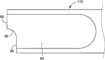
管嘴部56比载台30更沿轴向向前作为插入筒部设置在器具主体14上。如图5至7所示,对于管嘴部56,从载台30侧依次为基端部58、中间部60和前端部62,并且其总体呈现随着从基端侧至前端侧延伸而变得渐缩的外形形状。基端部58和前端部62呈大致恒定的截面形状沿轴向直线延伸。同时,中间部60是锥形逐渐收缩的截面部分,其截面形状随着沿轴向向前延伸而逐渐变小。The
在管嘴部56上,形成有处于与凹槽32连通的状态的、沿轴向的全长延伸的通孔64,并且通孔64的基端侧开口部66的宽度尺寸的大小与凹槽32的槽宽尺寸(透镜安放面34的宽度尺寸)大致相同。此外,通孔64在基端侧开口部66具有半月形或堆叠年糕形的开口截面,但该开口截面随着它接近前端侧开口部68而逐渐变形为大致椭圆形。这样,对于处于未变形的自由状态下的眼内透镜12,难以移动中间部60,并且光学部18在传送至中间部60的阶段弯曲并变形。如图7所示,管嘴部56的通孔64具有水平摊开的扁平截面形状,其中图5中的竖直方向(为载台30的宽度方向)为宽度方向,且图6中的竖直方向为高度方向。此外,其扁平率(扁平度)在基端侧开口部66处大于前端侧开口部68,并且在中间部60处逐渐改变。On the
此外,在通孔64上形成了从透镜安放面34无台阶地连接的底面70和位于底面70上方的顶面72。在底面70上,形成有跨基端部58和中间部60延伸的倾斜面74,该倾斜面74随着其沿轴向向前延伸而逐渐上升。底面70是用于夹持倾斜面74的轴向两侧部分的平坦面。同时,顶面72是沿轴向的全长不存在任何台阶的平坦面。Furthermore, a
在基端部58的底面70的宽度方向中央部分处形成有朝顶面72突出的一对导轨76、76。导轨76、76是沿轴向直线延伸预定尺寸的突出部,并且它们的前端部分(轴向前侧端部)处于倾斜面74的前端(轴向前端)处。应注意,通过随着倾斜面74沿轴向向前延伸而逐渐上升,使导轨76、76的前端部随着它们朝前端部延伸而逐渐进入底面70中并具有与底面70相同的高度位置。同时,导轨76、76的后端部经过基端部58的后端向透镜安放面34伸出。这种导轨76、76彼此大致平行地形成,在包围底面70的宽度方向中心的宽度方向上隔开预定距离。A pair of
在基端部58的顶面72上的宽度方向两端部上,分别形成有朝底面70突出的侧轨78。侧轨78沿轴向直线延伸预定尺寸地突出,并且前端部(轴向前侧前端部)位于与导轨76、76的前端部大致相同的轴向位置。侧轨78的前端部随着其朝前端部(轴向向前方向)延伸而逐渐进入管嘴部56的内表面中,并与管嘴部56的内表面齐平。同时,侧轨78的后端部定位在变成基端部58的后端的基端侧开口部66处。这种侧轨78彼此大致平行地形成。Side rails 78 protruding toward the
从这种器具主体14的轴向的后方,推压部件16插入中心孔26并附接在器具主体14上。如图8和图9所示,推压部件16大致呈棒形,并且配设有处于轴向前侧的作用部80和比作用部80处于轴向更后侧的插入部82。From the axial rear of such a
作用部80具有沿轴向直线延伸的棒形,具有大致椭圆形的固定截面形状,并且如图10和图11中展开地示出,其前端部84具有比基端部小的宽度方向(图11中的竖直方向)尺寸。The
前端部84上形成有作为沿轴向展开特定长度的接合部形成的台阶面86。这样,在前端部84上,在高度方向上侧(凹槽32的开口侧)形成有夹持台阶面86的光学部迫压面88,而且,在高度方向下侧(凹槽32的下侧,具体而言,透镜安放面34侧)形成有支持部迫压面90。光学部迫压面88比支持部迫压面90更处于推压部件16的轴向向前方向。The
只要台阶面86轴向尺寸(深度尺寸)具有可与支持部20b接合的大小,它就未特别受到限制,但它优选大于支持部20b的宽度尺寸的一半。如后文所述,可借助于台阶面86实现支持部20b的稳定固定。The axial dimension (depth dimension) of the stepped
只要支持部迫压面90的高度方向尺寸具有它可与支持部20b接合的大小,它就未受到特别限制,但优选它大于支持部20b的高度尺寸(厚度尺寸)。这使得可以实现支持部20b被支持部迫压面90稳定地固定。The height direction dimension of the support
应注意,在作用部80的宽度方向两侧设有薄板形增强肋92,从而确保作用部80的强度。It should be noted that thin plate-shaped reinforcing
同时,插入部82呈总体具有字母H形截面的直线延伸的棒形,并且在其后端处,一体形成有沿轴线直角方向变宽的迫压板94,该迫压板94增加了在推动推压部件16时的推力。Meanwhile, the
这种推压部件16通过从作用部80侧插入主体筒部28而被附接在器具主体14上。因此,获得了眼内透镜插入器具10。当将推压部件16附接在器具主体14上时,推压部件16相对于器具主体14的初始位置由设置在插入部82上的接合爪96设定,该接合爪96与在主体筒部28上形成的接合孔98接合。通过接合爪96在接合孔98中的接合作用来防止该推压部件16从主体筒部28被拔出,且能够利用沿推动方向的预定阻力来向主体筒部28移位。Such a pressing
此外,眼内透镜12被安置在眼内透镜插入器具10中,如上所述,推压部件16在相对于器具主体14的初始位置处被附接。Further, the
具体而言,如图12所示,对于器具主体14,通过在盖体48打开的状态下将眼内透镜12容纳在打开的载台30的凹槽32中,将眼内透镜12布置在载台30中。尤其是在此实施例中,眼内透镜12在光学部后表面24位于下侧的情况下被容纳在凹槽32中,且其借助于附接在载台30上的支承部件36的作用突出部40a、40a定位和安置。在此状态下,眼内透镜21的光学部后表面24的中央部分在与导轨76、76相接触之后被安放。Specifically, as shown in FIG. 12, for the device
眼内透镜12的支持部20a、20b的基端部被安放在两个作用突出部40a、40a的顶端面上,实质上整个眼内透镜12从凹槽32的底面被向上带动,并且可安置在尽可能地避免了底面上的接触应力对光学部18的影响的状态下。The base end portions of the
此外,由两个作用突出部40a、40a定位的眼内透镜12被保持在光学部18上的作用应力和变形减轻的自由状态下,并且一对支持部20a、20b朝器具主体14的轴向(前后方向)两侧伸出。此外,比光学部18更向轴向向后定位的支持部20b从位于其初始位置的推压部件16的光学部迫压面88沿推压方向稍微向前分离地定位。In addition, the
通过使从上侧设置在推压部件16的前端部84上的台阶面86在支持部20b上重叠,可以在透镜安放面34侧迫压支持部20b,并使支持部20b朝透镜安放面34接近地移位。这种情况下,不需要在盖体48上设置迫压部54。By overlapping the stepped
如上所述,在以此方式将眼内透镜12容纳在载台30的凹槽32内之后,通过关闭盖体48,凹槽32的上侧开口被盖体48覆盖。这样,如图13至15所示,眼内透镜12被容纳在器具主体14内。在盖体48处于关闭状态的情况下,设置在盖体48上的接合片100与设置在载台30上的接合凹口102接合,并且维持了盖体40的关闭状态。As described above, after the
此外,在盖体48关闭的状态下,如图13所示,一个迫压部54比推压部件16在支持部20b上的接触位置更多地与基端侧接触,并且比由作用突出部40a定位的位置更多地与伸出端侧接触,而且另一迫压部54比推压部件16在支持部20b上的接触位置更多地与伸出端侧接触。因此,如图16所示,推压部件16在支持部20b上的接触位置比在推压部件16上形成的台阶面86更处于沿高度方向的下侧。In addition, in the state where the
推压部件16也可在眼内透镜12被容纳在载台30的凹槽32内之前被插入器具主体14中并被安置在初始位置,但也可在眼内透镜12被容纳在凹槽32内之后或者还在盖体48被关闭之后将推压部件16插入器具主体14中。The pushing
此后,提供被容纳并包装在气密外壳等等中运输的眼内透镜插入器具10,眼内透镜12被安置在眼内透镜插入器具10中。此时,通过在包装在密封外壳中之前或之后的工序或通过包装前和包装后的工序,施行合适的消毒等。Thereafter, the intraocular
顺便说一下,当使用以此方式提供的眼内透镜插入器具10将眼内透镜12插入眼内时,首先,在手术现场从包装取出眼内透镜插入器具10,将支承部件36拉至载台30下方,并将其从器具主体14除去。因此,取消了由在支承部件36上形成的多个作用突出部40a、40a定位眼内透镜12,并且可以使眼内透镜12在载台30的透镜安放面34上方移动。By the way, when the
可通过在盖体48上形成的注射孔104将合适的润滑剂注入载台30或管嘴部56内部。这样,在利用推压部件16推压之前,可使眼内透镜12从导轨76、76浮起。结果,如后文将描述的,支持部20b更容易进入已弯曲变形为山状弯折状态的光学部18的内部,或者更容易在光学部18弯曲变形为山状弯折状态之前进入其下方。A suitable lubricant may be injected into the interior of the
当支承部件36从器具主体14被除去时,管嘴部56的前端侧开口部68被插入设置在眼组织中的切口。然后,在维持管嘴部56在切口中的插入状态的同时,将推压部件16推入器具主体14中。When the
同时,推压部件16在支持部20b上的接触位置比在推压部件16上形成的台阶面86更处于透镜安放面34侧,因此当推压部件16被推入器具主体14中时,如图17所示,轴向向后(向后移动方向)定位在眼内透镜12中的支持部20b进入在推压部件16上形成的台阶面86的下侧,并与支持部迫压面90接触。结果,如图18所示,通过支持部20b被支持部迫压面90向光学部18侧迫压,其沿接近光学部18的方向弯曲变形。At the same time, the contact position of the pressing
当支持部20b向光学部18侧弯曲变形为光学部18与外周面相接触的程度时,来自推压部件16的迫压力经由支持部20b传递至光学部18。结果,整个眼内透镜12在被推压部件16迫压的状态下移向管嘴部56。When the supporting
在支持部20b与支持部迫压面90相接触的状态下,当光学部迫压面88比支持部20b更处于向前移动方向上时,通过推压部件16的光学部迫压面88与光学部18的外周面接触,推压部件16的迫压力被直接传递至光学部18。此时,支持部20b可以与光学部18的外周面接触,也可以不接触。In the state where the supporting
在支持部20b被支持部迫压面90迫压一定时间后,迫压部54、54将支持部20b推向透镜安放面34侧。因此,当支持部20b开始被支持部迫压面90迫压时,支持部20b与台阶面86之间形成了间隙。After the
当在被推压部件16迫压的状态下移动的支持部20b从它被迫压部54、54固定的位置被除去时,支持部20b通过其自身的弹性向高度方向上侧(凹槽32的开口侧)移位。此时,台阶面86位于支持部20b上方,因此支持部20b与台阶面86接触。因此,当支持部20b被支持部迫压面90迫压时,通过台阶面86防止沿高度方向向上移位。When the supporting
如图19A所示,对于被传送到基端部58的眼内透镜12,光学部后表面24的中央部分与导轨76、76相接触,并且侧轨78、78在光学部前表面22处与在正交于推压方向的方向上的两侧端部相接触。在朝向顶面72的外力被施加至光学部后表面24的中央部分的同时,朝向底面70的外力在光学部前表面22处被施加至在正交于推压方向的方向上的两侧端部。结果,对于眼内透镜12的光学部18,光学部前表面22变成朝向位于竖直方向上侧的顶面72凸起,并且还使脊线变形为沿眼内透镜12的移动方向延伸的山状弯折。应注意,在图19中,将变形为山状弯折的眼内透镜12的光学部18的状态作为模型示出,并且省略了支持部20a、20b。As shown in FIG. 19A , for the
如图19B所示,当通过基端部58施加了初始山状弯折状态变形的眼内透镜12经中间部60变形为较小时,它被朝管嘴部56的前端侧开口部68传送。此时,光学部18沿通孔64的内表面形状变形,山状弯折状态进一步发展,并且光学部18前表面22在接触顶面72的状态下呈圆形。然后,如图19C所示,光学部18通过通孔64而在管嘴部56的前端部62处变圆而呈小的大致椭圆形,该通孔64随着其向前端部62延伸而逐渐变成大致椭圆形。As shown in FIG. 19B , when the
具体而言,在此实施例中,构造有变形引导部件,该变形引导部件包括一对导轨76、76、一对侧轨78、78、和在管嘴部56上形成的特殊形状的通孔64,并且变形引导部由一对导轨76、76和一对侧轨78、78构成。Specifically, in this embodiment, a deformation guide member including a pair of
此外,如上所述,当光学部18开始变形为山状弯折状态时,在推压部件16的向前推压方向上出现一空间(间隙),该空间(间隙)在变形为山状弯折状态的光学部18的光学部后表面24侧(凹侧)形成。当光学部18的变形体积变大时,如图20中的模型所示,与推压部件16的前端部84接合的支持部20b进入变形为山状弯折状态的光学部18的内侧(凹侧)。结果,支持部20b由于被光学部18包围而受到保护。然后,眼内透镜12在支持部20b以此方式被光学部18包围的状态下在管嘴部56内移动。In addition, as described above, when the
应注意,支持部20b进入光学部18的光学部后表面24侧并不限于在光学部18变形为山状弯折状态时。例如,也可利用光学部18导轨76、76的浮起体积或支持部20b在推压部件16推动支持部20b之前被迫压部54、54的推入体积来使支持部20b在光学部18变形为山状弯折状态之前进入光学部后表面24。It should be noted that entry of the
此外,处于眼内透镜12推压方向前方的支持部20a进入变圆的光学部18的内部,伴随着光学部18对应于通孔64内表面形状而变圆。这样,如图20所示,通孔64内部的眼内透镜12上呈现折卷状态。In addition, the
然后,在支持部20a、20b进入弯曲变形的光学部18的内侧(凹侧)的状态下,眼内透镜12从管嘴部56的前端侧开口部68被推出并插入眼内。Then, the
如上所述,对于眼内透镜插入器具10,在形成在推压部件16上的台阶面86下方滑动的状态下,支持部20b被推向光学部18,因此可以阻止支持部20b沿光学部18凸起的方向(凹槽32开口侧)移位。结果,当光学部18进入山状弯折状态时,支持部20b可进入光学部18凹侧(内侧)。As described above, with the intraocular
尤其是,对于处于关闭状态的盖体48,支持部20b被两个迫压部54、54推向透镜安放面34侧,因此在眼内透镜12开始被推压部件16推压之前,可使支持部20b比台阶面86更接近于透镜安放面34。因此,当眼内透镜12开始被推压部件16推压时,支持部20b可以可靠地在台阶面86下方滑动。结果,可以有效地抑制支持部20b的向上移位。In particular, for the
此外,当眼内透镜12被推压部件16推压时,光学部18弯曲变形为山状弯折状态,因此不需要提前使光学部18弯曲变形为山状弯折状态并且将眼内透镜12安置在载台30中。这样,将眼内透镜12安置在载台30中的作业更容易。In addition, when the
此外,与三件式结构眼内透镜相比,眼内透镜12具有整体结构,其中支持部20a、20b体积较大,但使支持部20b进入在变形为山状弯折状态的光学部18的凹侧(内侧)形成的相对大的间隙。结果,即使对于整体结构眼内透镜12,也可充分确保用于支持部20b脱开的空间。In addition, compared with the intraocular lens of the three-piece structure, the
此外,与三件式结构眼内透镜相比,眼内透镜12具有整体结构,其中支持部20a、20b具有低刚性,但由于受到保护以便使光学部18在支持部20b变形为山状弯折状态的同时包围支持部20b,所以可有效地避免损伤支持部20b。Furthermore, compared with the three-piece structure intraocular lens, the
变形引导部件并不限于此实施例所示的由各对导轨76、76、侧轨78、78和通孔64组成的结构。例如,即使对于未配设导轨76和侧轨78的通孔64,通过适当设定截面形状、推压方向等的变化模式,也可构成使眼内透镜12弯折变形为山形的变形引导部件,并且可通过在通孔64内局部形成凸部和凹部等而构成变形引导部件。The deformation guide member is not limited to the structure consisting of each pair of
此外,变形引导部件不仅可以是光学部18如上所述变形为山状弯折状态的部件,而是可以是光学部18变形为谷状弯折状态的部件,其中使光学部后表面24朝处于高度方向下部的底面70凸起的谷线沿眼内透镜12移动方向12延伸。作为实现谷状弯折状态的变形引导部件,例如,如图21所示,可采用具有其中前述实施例的通孔64竖直地翻转的截面形状的通孔等。In addition, the deformation guide member may be not only a member in which the
当采用该变形引导部件时,如果设有迫压部54,则如图22所示,迫压部54设置成在透镜安放面34上突出。支持部20b被沿高度方向(凹槽32开口侧)向上迫压,并且可以在被推压部件16推压之前使支持部20b向上侧移位。为使支持部20b更容易相对于光学部18向上侧相对移位,也可利用左、右引导板部50、50或中央引导板部52将光学部18推向透镜安放面34侧。作为推压部件,可采用配设有相对于前述实施例的前端部84竖直地翻转的形状的前端部的推压部件。When this deformation guide member is used, if the
如果采用实现光学部18的谷状弯折状态的变形引导部件,则迫压部54也可设置成向支承部件36的基板部38突出。这种情况下,在凹槽32的底壁上形成有插入通孔,迫压部54被插入该插入通孔,并且在支承部件36附接在器具主体14上的状态下,可以采用穿过插入通孔插入的迫压部54在透镜安放面34上突出的方法。If a deformation guide member that realizes the valley-like bending state of the
即使在采用实现了光学部18的谷状弯折状态的变形引导部件的情况下,迫压部54也不是绝对必要的。也可以将支持部20b安放在于推压部件16的前端部部84上形成的台阶面86上,并向上侧提升支持部20b。Even in the case of employing a deformation guide member that realizes the valley-like bent state of the
也可利用与器具主体14的中心轴线平行地延伸的脊线来使光学部18弯曲变形以便在凹槽32水平宽度方向向外(具体而言,图14中向左或向右)凸起。这种情况下,作为变形引导部件,可采用诸如前述实施例的通孔64围绕器具主体14的中心轴线转动90度的具有一定截面形状的通孔等。眼内透镜12在凹槽32被竖直安放的情况下并在光学部前表面22或光学后表面24处于朝向凹槽32的向外水平宽度方向的状态下被安置在载台30中。对于推压部件,可以采用配设有诸如前述实施例的前端部84围绕中心轴线转动90度之类的前端部的推压部件。这样,抑制了支持部20b沿光学部18变成凸起的方向移位,并且与前述实施例一样,可以使支持部20b进入光学部18的凹侧(内侧)。The
接下来将描述本发明的另一实施例的眼内透镜插入器具。以下记载的第二至第五实施例各者示出了用于第一实施例的眼内透镜插入器具中的推压部件的另一模式的示例。对于这些实施例,仅描述与第一实施例不同的部分,并且对于具有与第一实施例相同结构的部件和零件,我们将利用与第一实施例相同的代号来描述它们。Next, an intraocular lens insertion device of another embodiment of the present invention will be described. Each of the second to fifth embodiments described below shows an example of another mode of the urging member used in the intraocular lens insertion device of the first embodiment. For these embodiments, only the parts different from the first embodiment will be described, and for components and parts having the same structure as the first embodiment, we will describe them using the same codes as the first embodiment.
图23示出了构成本发明的第二实施例的推压部件106。该推压部件106具有在台阶面86和光学部迫压面88的相应边界部以及台阶面86和支持部迫压面90的边界部处在表面侧视图(对应于第一实施例的图10的轴向直角方向视图)中呈弧形弯曲的引导面108a、108b。应注意,虽然前引导面108a是向外凸起的1/4周圆弧截面,但后引导面108是外凹的1/4周圆弧截面。FIG. 23 shows a
对于配设有这种推压部件16的眼内透镜插入器具,在眼内透镜12被推压部件16推压之前,即使支持部20b比台阶面86更在上侧,支持部20b也被引导面108a引向接合部。具体而言,推压部件106向前移动,并且如果支持部20b与前引导面108a相接触,则通过支持部20b在引导面108a上滑动,支持部20b移向台阶面86下方。这样,可阻止支持部20b向上移位。With the intraocular lens insertion device equipped with such a pushing
此外,当推压部件106推压眼内透镜12时,支持部20b在台阶面86上滑动之后,通过在后引导表面108b上滑动,支持部20b在从台阶面86向下分离的位置接触支持部迫压面90。这样,可在更接近透镜安放面34的状态下推动支持部20b。结果,支持部20b甚至更容易进入光学部18的光学部后表面24侧。In addition, when the urging
不需要台阶面86的前端和后端都形成引导面108a、108b。例如,如图24所示,也可仅形成前引导面108a。这种情况下,未设置第一实施例的迫压部54,并且即使支持部20b未提前接近透镜安放面34移位,支持部20b也容易进入台阶面86下方。It is not necessary that both the front end and the rear end of the
此外,如图25所示,可以仅形成后引导面108b。这种情况下,可使支持部20b更加接近透镜安放面34,因此即使在光学部18由于从注射孔104注射的润滑剂而未基于浮力从透镜安放面34充分浮起的情况下,或者在支持部20b未被迫压部54充分推动的情况下等等,支持部20b也易于进入光学部18的光学部后表面24侧。In addition, as shown in FIG. 25, only the
此外,只要引导面108a、108b可引导支持部20b,就不需要使其在如图23所示的侧视图中呈圆弧形状弯曲。例如,如图26所示,也可采用随着它沿轴向向后方向在图中逐渐朝下的倾斜表面作为引导面108a、108b。In addition, as long as the
接下来,图27示出了构成本发明的第三实施例的推压部件110。对于该推压部件110,随着其从轴向向前方向向后延伸而在向下朝向高度方向的台阶面86处提供平缓的倾斜。Next, FIG. 27 shows a
对于配设有这种推压部件110的眼内透镜插入器具,当眼内透镜12被推压部件110推压时,通过作用在支持部20b上的一部分推压力,支持部20b在台阶面86上滑动并接近透镜安放面34。因此,支持部20b更可靠地进入光学部18的光学部后表面24侧。With the intraocular lens insertion device equipped with such a pushing
具有如上所述的引导功能的台阶面86并不限于图27所示的台阶面。例如,如图28所示,它也可以是在侧视图中呈圆弧形状弯曲的台阶面86。The stepped
此外,图29示出了构成本发明的第四实施例的推压部件112。该推压部件112具有倾斜,随着其沿轴向向后延伸使得光学部迫压面88逐渐朝向下方。Furthermore, FIG. 29 shows a
对于配设有这种推压部件12的眼内透镜插入器具,即使支持部20b未提前比台阶面86更处于透镜安放面34侧,通过与光学部迫压面88相接触的支持部20b在光学部迫压面88上滑动并基于接触力的部分力作用而向下移位,支持部20b也在台阶面86的底部进入。For the intraocular lens insertion device equipped with such a
具有如上所述的引导功能的光学部迫压面88并不限于图29所示的迫压面。例如,如图30所示,它也可以是在侧视图中呈圆弧形状弯曲的光学部迫压面88。The optical
此外,图31示出了构成本发明的第五实施例的推压部件114。该推压部件114具有在前端部84的前顶端部形成的在侧视图中向外凸起的呈圆弧形状弯曲的引导面116。如图32所示,该引导面116在侧视图中也可以是随着其从前向后延伸而逐渐向上倾斜的斜切形状的倾斜表面。Furthermore, FIG. 31 shows a
利用其中形成有这种引导面116的推压部件114,当进行相对于眼内透镜插入器具推动推压部件114的操作时防止了卡挂,并且可以更平稳地推压眼内透镜。With the urging
此外,在图33中,示出了构成本发明的第六实施例的推压部件118。该推压部件118具有接合突出部120,接合突出部120与在前端部84的高度方向上侧大致一半的区域内沿推压部件118的轴向向前突出的接合部一体形成。Furthermore, in FIG. 33 , a pressing
接合突出部120在侧视图中具有大致直角三角形形状,并且在侧视图构成倾斜侧的光学部迫压面的侧面122是随着其从前向后逐渐向下移动而倾斜的表面。于是,该侧面122在推压部件118的前端部84的高度方向上侧的大致一半区域内构成前端面。大致为推压部件118的前端部84的高度方向下半部的区域与第一实施例中一样是具有沿推压部件118的轴向直角方向变宽的平面形状的支持部迫压面90。The engaging
对于配设有这种推压部件118的眼内透镜插入器具,当利用推压部件118推压眼内透镜12时,与接合突出部120的侧面122相接触的支持部20b借助于部分接触力的作用向下滑动而产生位移。这样,支持部20b移向透镜安放面34侧。结果,支持部20b更容易进入弯曲变形的光学部18的内侧(凹侧)。With the intraocular lens insertion device equipped with such a pushing
具有如上所述的引导功能的接合突出部120的侧面122并不限于图33所示的侧面。例如,如图34所示,它也可以在侧视图中呈现外凹的圆弧形状弯曲。The side face 122 of the
此外,图35示出了构成本发明的第七实施例的推压部件124。该推压部件124是作为前端面126的逐渐朝下的倾斜面,光学部迫压面(其上部)和支持部迫压面(其下部)跨整个前端部84从前向后延伸。此外,接合部由该前端面126构成。Furthermore, FIG. 35 shows a
对于配设有这种推压部件124的眼内透镜插入器具,当利用推压部件124推压眼内透镜12时,与前端面126相接触的支持部20b通过部分接触力的作用而在前端面126上沿向下的方向滑动并移位。支持部20b移向透镜安放面34侧。结果,支持部20b更容易进入弯曲变形的光学部18的内侧(凹侧)。For the intraocular lens insertion device equipped with such a pushing
具有如上所述的引导功能的前端部84的前端面126并不限于图35所示的前端面。例如,如图36所示,前端部84的前端面126也可在侧视图中具有呈圆弧弯曲的形状。The
虽然已详细描述本发明的实施例,但本发明并不限于这些特定记载。Although the embodiments of the present invention have been described in detail, the present invention is not limited to these specific descriptions.
例如,在前述实施例中,支承部件36被可除去地组装在器具主体14的载台30上,并且借助于该支承部件36的作用突出部40a、40a、40b、40b,眼内透镜12被上提并且被安置在尽可能多地避免与光学部18相接触的状态下,但这种支承部件36对本发明而言并不是必需的。具体而言,也可将眼内透镜12直接安放和安置在载台30的透镜安放面34上,而不在器具主体14的载台30上设置通孔44a、44a、44b、44b,且不采用支承部件36。For example, in the foregoing embodiments, the supporting
此外,当不采用这种支承部件36时,代替在提前安置并包装的状态下提供眼内透镜12,优选提供与眼内透镜插入器具10分开包装的眼内透镜12并在进行手术时解开它,并且将它容纳并安置在眼内透镜插入器具10的载台30的透镜安放面34上。这使得可以避免归咎于在透镜安放面34相对于眼内透镜12的光学部18的储存和分配过程中长时间施加直接接触应力的问题。In addition, when such a supporting
即使采用支承部件36,例如,当接触眼内透镜12的光学部18或者支持部20a、20b的推压方向的中间部或前端部等等时,也可在支承这些部位的位置等处形成作用突出部。Even if the
决定眼内透镜光学部的变化模式的器具主体13、载台30或插入筒部(管嘴部56)等的形状和结构是当将眼内透镜插入眼内时根据变形目标形状适当地设定的形状和结构,并且例如包括是否采用导轨76、76或侧轨78、78等,并不限于实施例中记载的形状和结构。具体而言,当插入眼内透镜时使眼内透镜变小的模式并不限于如前文所述的山状弯折状态或谷状弯折状态,并且存在现有技术中公知的诸多变体,并且具体而言,可用于诸如圆形卷起等变型中,并且公知现有技术的各种结构可根据目标变型形状而用于本发明的眼内透镜插入器具。The shape and structure of the device main body 13, the
此外,对于前述实施例,眼内透镜12在自由状态下被平放在透镜安放面34上,但是当将眼内透镜12安置在载台30中时,也可使光学部18处于脊线沿器具主体14的轴向延伸的山状弯折状态或谷线沿器具主体14的轴向延伸的谷状弯折状态。作为提前将光学部18设置成山状弯折状态或谷状弯折状态的方法,例如,可采用使在载台30上形成的凹槽32的槽宽尺寸较小的方法等。In addition, with the foregoing embodiments, the
附图标记说明Explanation of reference signs
10:眼内透镜插入器具;12:眼内透镜;14:器具主体;16:推压部件;18:光学部;20a:支持部;20b:支持部;30:载台;54:迫压部;56:管嘴部(插入筒部);64:通孔(变形引导部件);76:导轨(变形引导部件,变形引导部);78:侧轨(变形引导部件,变形引导部);86:台阶面(接合部)10: Intraocular lens insertion device; 12: Intraocular lens; 14: Device main body; 16: Pushing part; 18: Optical part; 20a: Supporting part; 20b: Supporting part; 30: Carrier; 54: Pressing part ;56: nozzle part (insertion cylinder part); 64: through hole (deformation guide part); 76: guide rail (deformation guide part, deformation guide part); 78: side rail (deformation guide part, deformation guide part); 86 : Step surface (joint part)
Claims (6)
Applications Claiming Priority (1)
| Application Number | Priority Date | Filing Date | Title |
|---|---|---|---|
| PCT/JP2009/006173 WO2011061791A1 (en) | 2009-11-17 | 2009-11-17 | Intraocular lens insertion device |
Publications (2)
| Publication Number | Publication Date |
|---|---|
| CN102647958A true CN102647958A (en) | 2012-08-22 |
| CN102647958B CN102647958B (en) | 2014-11-26 |
Family
ID=44059295
Family Applications (1)
| Application Number | Title | Priority Date | Filing Date |
|---|---|---|---|
| CN200980162482.8A Expired - Fee Related CN102647958B (en) | 2009-11-17 | 2009-11-17 | Intraocular lens insertion device |
Country Status (7)
| Country | Link |
|---|---|
| US (2) | US20120253356A1 (en) |
| EP (1) | EP2502603B1 (en) |
| JP (1) | JP5412526B2 (en) |
| KR (1) | KR101630637B1 (en) |
| CN (1) | CN102647958B (en) |
| ES (1) | ES2617979T3 (en) |
| WO (1) | WO2011061791A1 (en) |
Cited By (1)
| Publication number | Priority date | Publication date | Assignee | Title |
|---|---|---|---|---|
| CN110167487A (en) * | 2017-01-13 | 2019-08-23 | 诺华股份有限公司 | Intraocular lens injector |
Families Citing this family (18)
| Publication number | Priority date | Publication date | Assignee | Title |
|---|---|---|---|---|
| EP2343029B1 (en) * | 2010-01-09 | 2015-05-06 | Nidek Co., Ltd. | Intraocular lens injection instrument |
| JP5666214B2 (en) * | 2010-09-01 | 2015-02-12 | 株式会社ニデック | Intraocular lens insertion device |
| JP5697962B2 (en) * | 2010-12-14 | 2015-04-08 | 興和株式会社 | Intraocular lens insertion device |
| US9427314B2 (en) | 2011-09-15 | 2016-08-30 | Kowa Company, Ltd. | Intraocular lens insertion tool |
| WO2013168410A1 (en) * | 2012-05-07 | 2013-11-14 | 株式会社メニコン | Intraocular lens insertion tool |
| MX349226B (en) | 2012-06-04 | 2017-07-19 | Alcon Pharmaceuticals Ltd | Intraocular lens inserter. |
| NZ702909A (en) | 2012-06-12 | 2017-01-27 | Altaviz Llc | Intraocular gas injector |
| ES2829610T3 (en) * | 2012-06-29 | 2021-06-01 | Kowa Co | Tool for inserting an intraocular lens and positioning element arranged in the insertion tool for an intraocular lens |
| JP6057749B2 (en) * | 2013-02-04 | 2017-01-11 | 興和株式会社 | Intraocular lens insertion device |
| EP3785668A1 (en) * | 2013-03-15 | 2021-03-03 | Alcon Inc. | Intraocular lens storage and loading devices and methods of use |
| WO2015012312A1 (en) * | 2013-07-24 | 2015-01-29 | 興和株式会社 | Intraocular lens-inserting instrument |
| AU2015240545B2 (en) | 2014-04-04 | 2019-07-11 | Alcon Inc. | Intraocular lens inserter |
| JP6500359B2 (en) * | 2014-07-14 | 2019-04-17 | 株式会社ニデック | Intraocular lens insertion device |
| US10588780B2 (en) | 2015-03-04 | 2020-03-17 | Alcon Inc. | Intraocular lens injector |
| US10172706B2 (en) | 2015-10-31 | 2019-01-08 | Novartis Ag | Intraocular lens inserter |
| US11000367B2 (en) | 2017-01-13 | 2021-05-11 | Alcon Inc. | Intraocular lens injector |
| US11224537B2 (en) | 2018-10-19 | 2022-01-18 | Alcon Inc. | Intraocular gas injector |
| JP7327956B2 (en) * | 2019-03-13 | 2023-08-16 | Hoya株式会社 | Intraocular lens insertion device |
Citations (13)
| Publication number | Priority date | Publication date | Assignee | Title |
|---|---|---|---|---|
| US5494484A (en) * | 1992-09-30 | 1996-02-27 | Staar Surgical Company | Deformable intraocular lens injecting device |
| WO1998005280A1 (en) * | 1996-08-02 | 1998-02-12 | Staar Surgical Company, Inc. | Spring biased deformable intraocular lens injecting apparatus |
| JP2003070829A (en) * | 2001-09-07 | 2003-03-11 | Canon Star Kk | Inserting utensil for intraocular lens |
| JP2004351196A (en) * | 2003-05-28 | 2004-12-16 | Alcon Inc | Lens delivery system |
| US20050171555A1 (en) * | 2004-01-30 | 2005-08-04 | Tran Son T. | Intraocular lens injector |
| JP2009018009A (en) * | 2007-07-11 | 2009-01-29 | Hoya Corp | Intraocular lens insertion device and intraocular lens movement control method |
| CN101422400A (en) * | 2007-11-01 | 2009-05-06 | 株式会社尼德克 | Intraocular lens injection instrument |
| EP2074961A1 (en) * | 2007-12-29 | 2009-07-01 | Nidek Co., Ltd. | Intraocular lens injection instrument |
| CN101500510A (en) * | 2006-08-11 | 2009-08-05 | 兴和株式会社 | Intraocular lens inserting instrument |
| EP2085053A1 (en) * | 2008-02-04 | 2009-08-05 | Nidek Co., Ltd. | Intraocular lens injection instrument |
| WO2009095975A1 (en) * | 2008-01-31 | 2009-08-06 | Menicon Co., Ltd. | Method of producing medical instrument |
| CN101511309A (en) * | 2006-09-05 | 2009-08-19 | 兴和株式会社 | Intraocular lens inserting instrument |
| US20090216244A1 (en) * | 2004-11-30 | 2009-08-27 | Joel Pynson | Two Stage Plunger for Intraocular Lens Injector |
Family Cites Families (7)
| Publication number | Priority date | Publication date | Assignee | Title |
|---|---|---|---|---|
| US7037312B2 (en) | 2001-09-07 | 2006-05-02 | Canon-Staar Co., Inc. | Insertion device for deformable intraocular lens |
| ES2305194T3 (en) * | 2002-12-09 | 2008-11-01 | ANTON MEYER & CO. AG | EMBOLO WATER FOR AN INTRAOCULAR LENS INJECTOR. |
| DE10310961B4 (en) * | 2003-03-13 | 2006-12-28 | Aixmed Gmbh | Posterior chamber lens |
| US8435289B2 (en) * | 2005-02-11 | 2013-05-07 | Abbott Medical Optics Inc. | Rapid exchange IOL insertion apparatus and methods of using |
| WO2008149794A1 (en) * | 2007-05-30 | 2008-12-11 | Hoya Corporation | Intraocular lens inserting tool |
| JP2009028223A (en) * | 2007-07-26 | 2009-02-12 | Hoya Corp | Intraocular lens inserting instrument |
| JP5189356B2 (en) * | 2007-12-28 | 2013-04-24 | 興和株式会社 | Intraocular lens insertion device |
-
2009
- 2009-11-17 US US13/509,467 patent/US20120253356A1/en not_active Abandoned
- 2009-11-17 CN CN200980162482.8A patent/CN102647958B/en not_active Expired - Fee Related
- 2009-11-17 KR KR1020127015537A patent/KR101630637B1/en not_active Expired - Fee Related
- 2009-11-17 WO PCT/JP2009/006173 patent/WO2011061791A1/en not_active Ceased
- 2009-11-17 JP JP2011541732A patent/JP5412526B2/en not_active Expired - Fee Related
- 2009-11-17 ES ES09851417.7T patent/ES2617979T3/en active Active
- 2009-11-17 EP EP09851417.7A patent/EP2502603B1/en not_active Not-in-force
-
2016
- 2016-04-27 US US15/140,108 patent/US9713528B2/en not_active Expired - Fee Related
Patent Citations (13)
| Publication number | Priority date | Publication date | Assignee | Title |
|---|---|---|---|---|
| US5494484A (en) * | 1992-09-30 | 1996-02-27 | Staar Surgical Company | Deformable intraocular lens injecting device |
| WO1998005280A1 (en) * | 1996-08-02 | 1998-02-12 | Staar Surgical Company, Inc. | Spring biased deformable intraocular lens injecting apparatus |
| JP2003070829A (en) * | 2001-09-07 | 2003-03-11 | Canon Star Kk | Inserting utensil for intraocular lens |
| JP2004351196A (en) * | 2003-05-28 | 2004-12-16 | Alcon Inc | Lens delivery system |
| US20050171555A1 (en) * | 2004-01-30 | 2005-08-04 | Tran Son T. | Intraocular lens injector |
| US20090216244A1 (en) * | 2004-11-30 | 2009-08-27 | Joel Pynson | Two Stage Plunger for Intraocular Lens Injector |
| CN101500510A (en) * | 2006-08-11 | 2009-08-05 | 兴和株式会社 | Intraocular lens inserting instrument |
| CN101511309A (en) * | 2006-09-05 | 2009-08-19 | 兴和株式会社 | Intraocular lens inserting instrument |
| JP2009018009A (en) * | 2007-07-11 | 2009-01-29 | Hoya Corp | Intraocular lens insertion device and intraocular lens movement control method |
| CN101422400A (en) * | 2007-11-01 | 2009-05-06 | 株式会社尼德克 | Intraocular lens injection instrument |
| EP2074961A1 (en) * | 2007-12-29 | 2009-07-01 | Nidek Co., Ltd. | Intraocular lens injection instrument |
| WO2009095975A1 (en) * | 2008-01-31 | 2009-08-06 | Menicon Co., Ltd. | Method of producing medical instrument |
| EP2085053A1 (en) * | 2008-02-04 | 2009-08-05 | Nidek Co., Ltd. | Intraocular lens injection instrument |
Cited By (2)
| Publication number | Priority date | Publication date | Assignee | Title |
|---|---|---|---|---|
| CN110167487A (en) * | 2017-01-13 | 2019-08-23 | 诺华股份有限公司 | Intraocular lens injector |
| CN110167487B (en) * | 2017-01-13 | 2021-04-20 | 爱尔康公司 | Intraocular lens injector |
Also Published As
| Publication number | Publication date |
|---|---|
| ES2617979T3 (en) | 2017-06-20 |
| HK1174527A1 (en) | 2013-06-14 |
| KR101630637B1 (en) | 2016-06-15 |
| WO2011061791A1 (en) | 2011-05-26 |
| US20120253356A1 (en) | 2012-10-04 |
| JPWO2011061791A1 (en) | 2013-04-04 |
| EP2502603A4 (en) | 2014-07-02 |
| EP2502603A1 (en) | 2012-09-26 |
| KR20120087175A (en) | 2012-08-06 |
| EP2502603B1 (en) | 2016-10-19 |
| CN102647958B (en) | 2014-11-26 |
| US20160278911A1 (en) | 2016-09-29 |
| US9713528B2 (en) | 2017-07-25 |
| JP5412526B2 (en) | 2014-02-12 |
Similar Documents
| Publication | Publication Date | Title |
|---|---|---|
| CN102647958B (en) | Intraocular lens insertion device | |
| US9072601B2 (en) | Intraocular lens insertion device | |
| JP4908977B2 (en) | Intraocular lens insertion device | |
| US9901442B2 (en) | Intraocular lens insertion device | |
| US6858033B2 (en) | Insertion system for intraocular lens | |
| JP5221949B2 (en) | Intraocular lens insertion device | |
| JP3876284B2 (en) | Lens insertion device for intraocular insertion | |
| US8535375B2 (en) | Intraocular lens insertion device | |
| US20030212407A1 (en) | Insertion system for intraocular lens | |
| US20010007942A1 (en) | Insertion system for intraocular lens | |
| US20010014808A1 (en) | Insertion device for a deformable intraocular lens | |
| JP4927473B2 (en) | Intraocular lens insertion device | |
| JP2017109096A (en) | Lens holder and injector for intraocular lens | |
| US20220117725A1 (en) | Intraocular lens implanter and preloaded type intraocular lens implantation device | |
| JP4557938B2 (en) | Intraocular lens insertion device | |
| HK1174527B (en) | Intraocular lens insertion device | |
| JP5096132B2 (en) | Intraocular lens insertion device |
Legal Events
| Date | Code | Title | Description |
|---|---|---|---|
| C06 | Publication | ||
| PB01 | Publication | ||
| ASS | Succession or assignment of patent right |
Owner name: KOWA COMPANY LTD. Free format text: FORMER OWNER: MENICON CO., LTD. Effective date: 20121026 |
|
| C41 | Transfer of patent application or patent right or utility model | ||
| TA01 | Transfer of patent application right |
Effective date of registration: 20121026 Address after: Aichi Prefecture, Japan Applicant after: KOWA Co.,Ltd. Address before: Aichi Prefecture, Japan Applicant before: MENICON Co.,Ltd. |
|
| C10 | Entry into substantive examination | ||
| SE01 | Entry into force of request for substantive examination | ||
| REG | Reference to a national code |
Ref country code: HK Ref legal event code: DE Ref document number: 1174527 Country of ref document: HK |
|
| C14 | Grant of patent or utility model | ||
| GR01 | Patent grant | ||
| REG | Reference to a national code |
Ref country code: HK Ref legal event code: GR Ref document number: 1174527 Country of ref document: HK |
|
| CF01 | Termination of patent right due to non-payment of annual fee |
Granted publication date: 20141126 Termination date: 20211117 |
|
| CF01 | Termination of patent right due to non-payment of annual fee |