JP2009028223A - Intraocular lens inserting instrument - Google Patents
Intraocular lens inserting instrument Download PDFInfo
- Publication number
- JP2009028223A JP2009028223A JP2007194558A JP2007194558A JP2009028223A JP 2009028223 A JP2009028223 A JP 2009028223A JP 2007194558 A JP2007194558 A JP 2007194558A JP 2007194558 A JP2007194558 A JP 2007194558A JP 2009028223 A JP2009028223 A JP 2009028223A
- Authority
- JP
- Japan
- Prior art keywords
- intraocular lens
- plunger
- tip
- insertion device
- eyeball
- Prior art date
- Legal status (The legal status is an assumption and is not a legal conclusion. Google has not performed a legal analysis and makes no representation as to the accuracy of the status listed.)
- Pending
Links
- 210000005252 bulbus oculi Anatomy 0.000 claims abstract description 15
- 238000003780 insertion Methods 0.000 claims description 35
- 230000037431 insertion Effects 0.000 claims description 35
- 238000003825 pressing Methods 0.000 claims description 4
- 238000003860 storage Methods 0.000 claims description 4
- 210000001508 eye Anatomy 0.000 abstract description 10
- 230000002093 peripheral effect Effects 0.000 description 24
- 230000003287 optical effect Effects 0.000 description 7
- 238000001356 surgical procedure Methods 0.000 description 3
- 208000002177 Cataract Diseases 0.000 description 2
- 238000002513 implantation Methods 0.000 description 2
- 229920003229 poly(methyl methacrylate) Polymers 0.000 description 2
- 239000004926 polymethyl methacrylate Substances 0.000 description 2
- 241000894006 Bacteria Species 0.000 description 1
- YKSSRNAGQDAYQH-JAMMHHFISA-N CC[C@H](C)CC(C)CN Chemical compound CC[C@H](C)CC(C)CN YKSSRNAGQDAYQH-JAMMHHFISA-N 0.000 description 1
- NIXOWILDQLNWCW-UHFFFAOYSA-N acrylic acid group Chemical group C(C=C)(=O)O NIXOWILDQLNWCW-UHFFFAOYSA-N 0.000 description 1
- 201000009310 astigmatism Diseases 0.000 description 1
- 238000005452 bending Methods 0.000 description 1
- 238000011109 contamination Methods 0.000 description 1
- 210000004087 cornea Anatomy 0.000 description 1
- 230000000694 effects Effects 0.000 description 1
- 238000004945 emulsification Methods 0.000 description 1
- 208000015181 infectious disease Diseases 0.000 description 1
- 238000004519 manufacturing process Methods 0.000 description 1
- 239000000463 material Substances 0.000 description 1
- 238000000034 method Methods 0.000 description 1
- 239000011347 resin Substances 0.000 description 1
- 229920005989 resin Polymers 0.000 description 1
- 230000000452 restraining effect Effects 0.000 description 1
- 210000003786 sclera Anatomy 0.000 description 1
- 229920002379 silicone rubber Polymers 0.000 description 1
- 239000007779 soft material Substances 0.000 description 1
- 230000009466 transformation Effects 0.000 description 1
Images


Landscapes
- Prostheses (AREA)
Abstract
Description
本発明は、白内障手術により摘出した水晶体の代わりに、眼球内に眼内レンズを移植するための眼内レンズ挿入器具に関するものであり、特に、眼内レンズを押出すためのプランジャーの先端形状に関する。 The present invention relates to an intraocular lens insertion device for implanting an intraocular lens in an eyeball instead of a lens removed by cataract surgery, and in particular, a distal end shape of a plunger for extruding the intraocular lens. About.
白内障手術においては、超音波乳化吸引(PEA)による混濁した水晶体の除去、および水晶体除去後の眼内への眼内レンズの埋植が広く行われている。眼内レンズには、その光学部がポリメチルメタクリレート(PMMA)などの硬質の材料からなる硬質眼内レンズと、シリコーンエラストマーや軟性アクリルなどの柔らかい材料からなる軟性眼内レンズとがある。 In cataract surgery, the removal of a turbid lens by ultrasonic emulsification and aspiration (PEA) and the implantation of an intraocular lens in the eye after removal of the lens are widely performed. The intraocular lens includes a hard intraocular lens whose optical part is made of a hard material such as polymethyl methacrylate (PMMA), and a soft intraocular lens made of a soft material such as silicone elastomer or soft acrylic.
硬質眼内レンズを使用する際には、光学部の径と略同じ幅の切開創を角膜、あるいは強膜に作製してレンズを挿入しなければならないのに対し、軟性眼内レンズを使用する際には、光学部を折り畳むことにより、光学部の径より小さな切開創からレンズを挿入することができる利点がある。さらに、手術後の角膜乱視や感染症を低減するためには、小さな切開創から眼内レンズを挿入することが好ましく、現在では軟性眼内レンズが好まれる傾向にある。 When using a hard intraocular lens, an incision with a width approximately the same as the diameter of the optical part must be made in the cornea or sclera and the lens must be inserted, whereas a soft intraocular lens is used. In this case, there is an advantage that the lens can be inserted from an incision smaller than the diameter of the optical part by folding the optical part. Furthermore, in order to reduce corneal astigmatism and infection after surgery, it is preferable to insert an intraocular lens through a small incision, and at present, a soft intraocular lens tends to be preferred.
また、眼内レンズを眼内に入れるために、細長い筒の中を通して眼内レンズを眼内へ導入する構造を有した専用の眼内レンズ挿入器具が使用されることもある。このような眼内レンズ専用の眼内レンズ挿入器具を使用することにより、3mmより小さな切開創口からレンズを眼内へ挿入することが可能である。 In order to put the intraocular lens into the eye, a dedicated intraocular lens insertion device having a structure for introducing the intraocular lens into the eye through an elongated tube may be used. By using such an intraocular lens insertion device dedicated to an intraocular lens, it is possible to insert the lens into the eye from an incision wound smaller than 3 mm.
更に、眼内レンズの取扱時における細菌による汚染や、眼内レンズの取扱時に起こり得る操作ミスの可能性を排除するために、レンズが予め眼内レンズ挿入器具内にセットされ、梱包、保管が可能なタイプの眼内レンズ挿入器具も開発されている。 Furthermore, in order to eliminate the possibility of contamination by bacteria during the handling of intraocular lenses and the possibility of operational errors that may occur during the handling of intraocular lenses, the lenses are set in advance in the intraocular lens insertion device, and packed and stored. Possible types of intraocular lens insertion devices have also been developed.
眼内レンズ挿入器具を用いて眼内レンズを眼内に挿入する場合には、挿入器具内で眼内レンズを押すためのプランジャー先端部と眼内レンズがしっかりかみ合っている必要がある。かみ合いが不充分であると、プランジャーと眼内レンズの位置関係がずれたり、プランジャーが眼内レンズの上に乗り上げたり、眼内レンズの下に入り込んだりすることで、眼内レンズの光学部や支持部をキズつけたり破損したり、あるいはプランジャーが眼内レンズを通過してしまい、眼内レンズを眼内に挿入できないこともある。 When an intraocular lens is inserted into the eye using an intraocular lens insertion device, it is necessary that the plunger tip for pushing the intraocular lens in the insertion device and the intraocular lens are firmly engaged. If the engagement is insufficient, the positional relationship between the plunger and the intraocular lens is shifted, or the plunger rides on the intraocular lens or enters under the intraocular lens. The part or the support part may be scratched or damaged, or the plunger may pass through the intraocular lens, and the intraocular lens may not be inserted into the eye.
このような問題点に対して、カートリッジ中心軸からオフセットされた丸い先端部を有するプランジャーを常時カートリッジ内壁に押圧することで、プランジャーの眼内レンズへの乗り上げを防止する技術が開示されている(例えば、特許文献1)。また、眼内レンズ挿入器具内での眼内レンズの移動時に、プランジャー先端部と眼内レンズのかみ合いをしっかりさせるため、図11〜図13示すにように筒状の本体と一体又は別体の眼内レンズ収納部3と、前記収納部3に収納された眼内レンズ2を押圧して眼球内に放出するためのプランジャー6とを備え、前記プランジャー6の先端部に突起50を設けた眼内レンズ移植装置が提案されている(例えば、特許文献2参照)。
近年においては小切開化の要望はますます強まり、それに伴い眼内レンズ挿入器具のノズル径も小さなものが要求されてきている。ノズル径が小さくなり、眼内レンズ挿入器具内での眼内レンズの摺動抵抗が大きくなると、上記従来技術によるプランジャーではプランジャーと眼内レンズとのかみ合わせが不充分なことが判ってきた。特に、1回限り使用し、その後は廃棄されるディスポーザブルタイプのインジェクターの場合、製作コストの低減を図るべくプランジャーは樹脂成型品から製作され、プランジャーの曲げ剛性は低い。そのためノズル先端部の口径を小さくすればするほど、プランジャーが弓状に変形し、先端部が眼内レンズの周縁から外れ、眼内レンズの光学部にプランジャーが乗り上げてしまい易くなる。 In recent years, there has been an increasing demand for a small incision, and accordingly, an intraocular lens insertion instrument having a small nozzle diameter has been demanded. When the nozzle diameter is reduced and the sliding resistance of the intraocular lens in the intraocular lens insertion device is increased, it has been found that the plunger according to the above prior art is insufficiently engaged between the plunger and the intraocular lens. . In particular, in the case of a disposable injector that is used only once and then discarded, the plunger is manufactured from a resin molded product in order to reduce the manufacturing cost, and the bending rigidity of the plunger is low. Therefore, the smaller the diameter of the nozzle tip, the more the plunger is deformed in an arcuate shape, the tip is disengaged from the peripheral edge of the intraocular lens, and the plunger is likely to ride on the optical part of the intraocular lens.
本発明は、上記従来技術が有する問題を解決すべくなされたものであり、眼内レンズの周縁部とプランジャーの先端部との係合をより確実にし、ノズル先端部の口径が小さく摺動抵抗が大きい場合であっても、安全確実に眼内レンズを眼内に放出できる眼内レンズ挿入器具を提供することを課題とする。 The present invention has been made in order to solve the above-described problems of the prior art, more reliably engages the peripheral portion of the intraocular lens and the tip of the plunger, and slides the nozzle tip at a small diameter. It is an object of the present invention to provide an intraocular lens insertion device capable of safely and reliably releasing an intraocular lens into the eye even when the resistance is large.
請求項1記載の発明は、変形可能な眼内レンズを眼球組織の切開創口より眼球内に挿入するための眼内レンズ挿入器具であって、筒状の本体と、前記本体と一体または別体の眼内レンズの収納部と、前記収納部に収納された前記眼内レンズを押圧して眼球内に放出するためのプランジャーとを備え、前記プランジャーの先端部に垂直エッジ捕捉部と水平エッジ捕捉部とを設けたことを特徴とするものである。
The invention according to
請求項2記載の発明は、請求項1記載の眼内レンズ挿入器具において、前記垂直エッジ捕捉部に突き当て部を設けたことを特徴とするものである。 According to a second aspect of the present invention, in the intraocular lens insertion device according to the first aspect, an abutting portion is provided in the vertical edge capturing portion.
請求項3記載の発明は、請求項1または2記載の眼内レンズ挿入器具において、前記水平エッジ捕捉部の先端面に傾斜を設けたことを特徴とするものである。 According to a third aspect of the present invention, in the intraocular lens insertion device according to the first or second aspect, the tip surface of the horizontal edge capturing portion is provided with an inclination.
請求項1記載の眼内レンズ挿入器具によれば、眼内レンズの眼内への挿入時に大きな摺動抵抗があったとしても、プランジャーの先端部において眼内レンズを確実に捕捉することができ、眼内レンズの光学部の上にプランジャーが乗り上がるのを防止できる。
According to the intraocular lens insertion device of
請求項2記載の眼内レンズ挿入器具によれば、垂直エッジ捕捉部に突き当て部により眼内レンズの変形量を制限することができるので、眼内レンズの過剰な変形を防止することができる。 According to the intraocular lens insertion device of the second aspect, since the deformation amount of the intraocular lens can be limited by the abutting portion against the vertical edge capturing portion, it is possible to prevent excessive deformation of the intraocular lens. .
請求項3記載の眼内レンズ挿入器具によれば、水平エッジ捕捉部の先端面に設けた傾斜により、プランジャーの先端が眼内レンズの周縁を一層確実に捕捉することができる。 According to the intraocular lens insertion device of the third aspect, the distal end of the plunger can capture the peripheral edge of the intraocular lens more reliably by the inclination provided on the distal end surface of the horizontal edge capturing portion.
以下、図面を参照して本発明の実施の形態について説明する。図1は本発明に係る眼内レンズ挿入器具の外観斜視図であり、図2は同断面図である。また、図3は眼内レンズ挿入器具の部品分解図である。 Embodiments of the present invention will be described below with reference to the drawings. FIG. 1 is an external perspective view of an intraocular lens insertion device according to the present invention, and FIG. 2 is a cross-sectional view thereof. FIG. 3 is an exploded view of components of the intraocular lens insertion device.
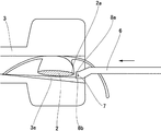
先ず、はじめに本発明が適用される眼内レンズ挿入器具1について説明する。本発明が適用される眼内レンズ挿入器具1の概略構成は、眼内レンズの収納部たるカートリッジ3と、前記カートリッジ3が一端に係止され他端に把持フランジ4が固定された本体たる筒状のハンドピース5と、前記ハンドピース5に挿通され押し棒13と一体化されたプランジャー6からなる。そして、前記プランジャー6の先端部には眼内レンズの周縁を捕捉するための垂直エッジ捕捉部7と水平エッジ捕捉部8が設けられている。
First, an intraocular
カートリッジ3は、その内部に眼内レンズを収納し、眼球組織の切開創口よりその先端部を眼球内に挿入して眼球内にレンズを放出するためのものであり、略中空の筒状をしていて、先細りとなるように形成されている。そして、カートリッジ3の術者側の端部は眼内レンズ挿入口3aに供され、先端側である他端は眼内レンズ放出口3bに供される。挿入口3aは眼内レンズを折り畳んでカートリッジ3内に装填するためのものであり、筒部には挿入溝3cが設けられている。この挿入溝3cがあることにより挿入器具(図示せず)を用いて眼内レンズを折り畳んだ状態でカートリッジ3内に容易に装填することができる。また、カートリッジ3の先端に位置する放出口3bは眼球組織の切開創口への挿入をし易くするため、切り口が斜めに形成されている。さらに、カートリッジ3の側面にはカートリッジ3をハンドピース5に係止するための翼部3dが2箇所に設けられている。
The
なお、本実施例では眼内レンズの収納部たるカートリッジ3と、本体たるハンドピース5を別体として構成しているが、カートリッジ3とハンドピース5を一体として構成することもできる。
In this embodiment, the
ハンドピース5は、その先端側に近い側面にカートリッジ3の翼部3dを案内する案内路を有する断面半円弧状の案内部5aが形成されており、案内部5aの先端側には、カートリッジ3の翼部3dを係止可能とする係止部5bが設けられている。また、ハンドピース5の他端には、押し棒13の外周面とハンドピース5の内周面との間にボールブシュ9が装着されている。さらに、ハンドピース5の他端にはキャップ11が固定され、このキャップ11には術者の把持を容易にするための把持フランジ4が固定されている。
The
プランジャー6には締結具12により押し棒13が一体化され、前述したハンドピース5とボールブッシュ9および把持フランジ4内に挿通されている。そして、押し棒13の術者側には、押し棒13の押し引きを容易にするためのエンドプレート14が固定されている。
A
次に、本発明の特徴的部分であるプランジャー6の先端部の形状について図4〜図7に基づいて説明する。プランジャー6の先端部は、垂直エッジ捕捉部7と水平エッジ捕捉部8a,8bとで構成されている。図4はカートリッジ3内に収納された眼内レンズ2の周縁2aをプランジャー6の先端部で捕捉する直前の状態を示すものである。また、図5はプランジャーの拡大側面図であり、図6はプランジャーの拡大正面図である。さらに、図7はプランジャー6の先端部が眼内レンズの周縁2aを捕捉した状態を示す側面図である。プランジャー6の先端部は、その根元部の軸心に対して若干下方にオフセットした位置に設けられている。このようにすることで、カートリッジ3内で凹状に折り畳まれた眼内レンズ2の光学部の周縁2a位置とプランジャーの先端部位置とを略一致させることができる。なお、カートリッジ3のレンズ収納部の下面には、プランジャー先端部の幅寸法より多少幅広の溝3eが傾斜をもって設けられている。
Next, the shape of the tip of the
ここで、プランジャー6の先端部には上部と下部の2箇所に水平エッジ捕捉部8a,8bが設けられ、これら2箇所の水平エッジ捕捉部8a,8bを連接するように中央部には、垂直エッジ捕捉部7が設けられている。これら2箇所の水平エッジ捕捉部8a,8bの先端面と垂直エッジ捕捉部7の先端面は同一平面をなすように形成されている。したがって、プランジャー6の先端部を正面から見ると、図6に示すように略「I」字状を呈することになる。
Here, the tip of the
図6,図7に示すプランジャー先端部の各部寸法の具体例を示すと、外径6mm,エッジ厚さ0.3mmの眼内レンズを、ノズル内径1.8mmのカートリッジを用いて眼内へ挿入する場合、W1=0.6mm,W2=0.8mm,H=0.2mm,D=0.5mm程度が適正値となる。 Specific examples of dimensions of the plunger tip shown in FIGS. 6 and 7 are as follows. An intraocular lens having an outer diameter of 6 mm and an edge thickness of 0.3 mm is inserted into the eye using a cartridge having a nozzle inner diameter of 1.8 mm. When inserted, W1 = 0.6 mm, W2 = 0.8 mm, H = 0.2 mm, and D = 0.5 mm are appropriate values.
次に、このような先端形状を有するプランジャー6が眼内レンズの周縁2aに当接する場合の作用について説明する。プランジャー6を前方に押し進めると、先ずプランジャーの垂直エッジ捕捉部7が眼内レンズの周縁2aに当接する。この段階では垂直エッジ捕捉部7と眼内レンズの周縁2aとの接触面積は小さく、眼内レンズの周縁2aの当接部は垂直エッジ捕捉部7から受ける圧力によりレンズ中心方向に向かって弾性変形することになる。一方、眼内レンズの周縁2aのうち、垂直エッジ捕捉部7と当接していない部分は外力を受けないことから殆ど弾性変形しない。その結果、プランジャー6の垂直エッジ捕捉部7は眼内レンズの周縁2aとの当接部に喰い込み、眼内レンズの周縁2aを確実に捕捉することが可能となる。いわゆるアンカー効果が発揮されることとなる。ここで、プランジャー6の先端部の上部と下部の2箇所に設けられた水平エッジ捕捉部8a,8bは、眼内レンズの周縁2aに直接喰い込むことはないが、垂直エッジ捕捉部7が眼内レンズの周縁2aを捕捉し始める際に上下方向の案内機能を果たすとともに、垂直エッジ捕捉部7が眼内レンズの周縁2aに喰い込んだ後において眼内レンズ2を上下方向に拘束する機能をも果たすことになる。このようにして本実施例による眼内レンズ挿入器具1によれば、プランジャー6の先端部において眼内レンズの周縁2aを確実に捕捉することができる。
Next, an operation when the
図8は、本発明の第2実施例を示すプランジャー6の先端部の側面図である。この実施例の基本構成は上記第1実施例と共通する。ただし、第1実施例においては2箇所の水平エッジ捕捉部8a,8bと垂直エッジ捕捉部7の先端面は同一平面をなすように形成されているが、第2実施例においては水平エッジ捕捉部8a,8bの先端面に内向きの傾斜が設けられている点が相違する。このように水平エッジ捕捉部8a,8bの先端面に傾斜を設けることにより、眼内レンズの周縁2aの上下方向位置が垂直エッジ捕捉部7の上下方向位置と多少ずれを生じている場合であっても、垂直エッジ捕捉部7が眼内レンズの周縁2aを捕捉し始める際に水平エッジ捕捉部8a,8bの傾斜面が上下方向の案内機能を果たすことになる。したがって、プランジャー6の先端部において眼内レンズの周縁2aをより一層確実に捕捉することができるようになる。
FIG. 8 is a side view of the distal end portion of the
図9は本発明の第3実施例を示すプランジャー先端部の斜視図であり、図10はその平面図である。本実施例によるプランジャー6には、垂直エッジ捕捉部7の両側部に突き当て部19が設けられている。すなわち、垂直エッジ捕捉部7の両側部であって、プランジャーの先端面から幾分後方(術者側)位置に突き当て部19が設けられている。このように突き当て部19を設けることにより、垂直エッジ捕捉部7が眼内レンズの周縁2aに喰い込む量を制限することができる。したがって、眼内レンズ2の過剰な変形を防止することができる。
FIG. 9 is a perspective view of a plunger tip portion showing a third embodiment of the present invention, and FIG. 10 is a plan view thereof. The
以上、本発明を実施例に基づいて説明したが、本発明は上記実施例に限定されるものではなく、種々の変形実施が可能である。例えば、上記実施例においては、上下一対の水平エッジ捕捉部8a,8bとの間に1個の垂直エッジ捕捉部7を設けているが、垂直エッジ捕捉部は複数個設けることとしてもよい。
As mentioned above, although this invention was demonstrated based on the Example, this invention is not limited to the said Example, A various deformation | transformation implementation is possible. For example, in the above embodiment, one vertical
1 眼内レンズ挿入器具
2 眼内レンズ
3 収納部(カートリッジ)
5 本体(ハンドピース)
6 プランジャー
7 垂直エッジ捕捉部
8a,8b 水平エッジ捕捉部
19 突き当て部
1 Intraocular
5 Body (handpiece)
6
8a, 8b Horizontal edge capture unit
19 Butting part
Claims (3)
The intraocular lens insertion device according to claim 1, wherein an inclination is provided on a distal end surface of the horizontal edge capturing unit.
Priority Applications (1)
| Application Number | Priority Date | Filing Date | Title |
|---|---|---|---|
| JP2007194558A JP2009028223A (en) | 2007-07-26 | 2007-07-26 | Intraocular lens inserting instrument |
Applications Claiming Priority (1)
| Application Number | Priority Date | Filing Date | Title |
|---|---|---|---|
| JP2007194558A JP2009028223A (en) | 2007-07-26 | 2007-07-26 | Intraocular lens inserting instrument |
Publications (1)
| Publication Number | Publication Date |
|---|---|
| JP2009028223A true JP2009028223A (en) | 2009-02-12 |
Family
ID=40399432
Family Applications (1)
| Application Number | Title | Priority Date | Filing Date |
|---|---|---|---|
| JP2007194558A Pending JP2009028223A (en) | 2007-07-26 | 2007-07-26 | Intraocular lens inserting instrument |
Country Status (1)
| Country | Link |
|---|---|
| JP (1) | JP2009028223A (en) |
Cited By (17)
| Publication number | Priority date | Publication date | Assignee | Title |
|---|---|---|---|---|
| KR20120087175A (en) * | 2009-11-17 | 2012-08-06 | 가부시끼가이샤 메니콘 | Intraocular lens insertion device |
| JP2013519429A (en) * | 2010-02-11 | 2013-05-30 | プレスバイテック インコーポレイテッド | Lens insertion apparatus and method |
| WO2014084355A1 (en) | 2012-11-29 | 2014-06-05 | 興和株式会社 | Intraocular lens insertion device |
| WO2015012312A1 (en) | 2013-07-24 | 2015-01-29 | 興和株式会社 | Intraocular lens-inserting instrument |
| US9693857B2 (en) | 2010-12-14 | 2017-07-04 | Kowa Company, Ltd. | Intraocular lens insertion apparatus |
| JP2019042127A (en) * | 2017-09-01 | 2019-03-22 | 株式会社ニデック | Intraocular lens insertion device |
| US10568735B2 (en) | 2017-01-13 | 2020-02-25 | Alcon Inc. | Intraocular lens injector |
| US10588780B2 (en) | 2015-03-04 | 2020-03-17 | Alcon Inc. | Intraocular lens injector |
| US10918519B2 (en) | 2010-12-14 | 2021-02-16 | Kowa Company, Ltd. | Intraocular lens insertion apparatus |
| US11000367B2 (en) | 2017-01-13 | 2021-05-11 | Alcon Inc. | Intraocular lens injector |
| JP2022549948A (en) * | 2019-09-30 | 2022-11-29 | アルコン インコーポレイティド | soft tip plunger |
| US11938019B2 (en) | 2007-05-30 | 2024-03-26 | Hoya Corporation | Intraocular lens insertion device |
| US12076231B2 (en) | 2018-05-25 | 2024-09-03 | Hoya Corporation | Intraocular lens injector |
| US12257145B2 (en) | 2018-05-16 | 2025-03-25 | HOYA Medical Singapore Pte. Ltd. | Intraocular lens injector with container |
| US12414852B2 (en) | 2016-06-28 | 2025-09-16 | HOYA Medical Singapore Pte. Ltd. | Intraocular lens injector |
| WO2025206267A1 (en) * | 2024-03-29 | 2025-10-02 | 興和株式会社 | Intraocular lens insertion tool |
| US12478467B2 (en) | 2019-03-13 | 2025-11-25 | HOYA Medical Singapore Pte. Ltd. | Intraocular lens injector |
Citations (4)
| Publication number | Priority date | Publication date | Assignee | Title |
|---|---|---|---|---|
| JPH0819558A (en) * | 1994-07-07 | 1996-01-23 | Canon Star Kk | Inserter for deformable intraocular lens |
| JP2000516487A (en) * | 1996-08-02 | 2000-12-12 | スター・サージカル・カンパニー,インコーポレイテッド | Spring-biased deformable intraocular lens injection device |
| WO2002071982A1 (en) * | 2001-01-26 | 2002-09-19 | Advanced Medical Optics, Inc. | Tepped oil insertion cartridge |
| WO2006070628A1 (en) * | 2004-12-27 | 2006-07-06 | Hoya Corporation | Intraocular lens implanting device |
-
2007
- 2007-07-26 JP JP2007194558A patent/JP2009028223A/en active Pending
Patent Citations (4)
| Publication number | Priority date | Publication date | Assignee | Title |
|---|---|---|---|---|
| JPH0819558A (en) * | 1994-07-07 | 1996-01-23 | Canon Star Kk | Inserter for deformable intraocular lens |
| JP2000516487A (en) * | 1996-08-02 | 2000-12-12 | スター・サージカル・カンパニー,インコーポレイテッド | Spring-biased deformable intraocular lens injection device |
| WO2002071982A1 (en) * | 2001-01-26 | 2002-09-19 | Advanced Medical Optics, Inc. | Tepped oil insertion cartridge |
| WO2006070628A1 (en) * | 2004-12-27 | 2006-07-06 | Hoya Corporation | Intraocular lens implanting device |
Cited By (25)
| Publication number | Priority date | Publication date | Assignee | Title |
|---|---|---|---|---|
| US11938019B2 (en) | 2007-05-30 | 2024-03-26 | Hoya Corporation | Intraocular lens insertion device |
| JP5412526B2 (en) * | 2009-11-17 | 2014-02-12 | 興和株式会社 | Intraocular lens insertion device |
| KR20120087175A (en) * | 2009-11-17 | 2012-08-06 | 가부시끼가이샤 메니콘 | Intraocular lens insertion device |
| KR101630637B1 (en) | 2009-11-17 | 2016-06-15 | 코와 가부시키가이샤 | Intraocular lens insertion device |
| JP2013519429A (en) * | 2010-02-11 | 2013-05-30 | プレスバイテック インコーポレイテッド | Lens insertion apparatus and method |
| US9017401B2 (en) | 2010-02-11 | 2015-04-28 | Presbitech, Inc. | Lens inserter apparatus and method |
| EP3235472A1 (en) | 2010-12-14 | 2017-10-25 | Kowa Company, Ltd. | Intraocular lens insertion apparatus |
| US10918519B2 (en) | 2010-12-14 | 2021-02-16 | Kowa Company, Ltd. | Intraocular lens insertion apparatus |
| US9693857B2 (en) | 2010-12-14 | 2017-07-04 | Kowa Company, Ltd. | Intraocular lens insertion apparatus |
| KR20150090898A (en) | 2012-11-29 | 2015-08-06 | 코와 가부시키가이샤 | Intraocular lens insertion device |
| WO2014084355A1 (en) | 2012-11-29 | 2014-06-05 | 興和株式会社 | Intraocular lens insertion device |
| US9855138B2 (en) | 2012-11-29 | 2018-01-02 | Kowa Company, Ltd. | Intraocular lens insertion device |
| WO2015012312A1 (en) | 2013-07-24 | 2015-01-29 | 興和株式会社 | Intraocular lens-inserting instrument |
| US10588780B2 (en) | 2015-03-04 | 2020-03-17 | Alcon Inc. | Intraocular lens injector |
| US12414852B2 (en) | 2016-06-28 | 2025-09-16 | HOYA Medical Singapore Pte. Ltd. | Intraocular lens injector |
| US10568735B2 (en) | 2017-01-13 | 2020-02-25 | Alcon Inc. | Intraocular lens injector |
| US11000367B2 (en) | 2017-01-13 | 2021-05-11 | Alcon Inc. | Intraocular lens injector |
| JP7035384B2 (en) | 2017-09-01 | 2022-03-15 | 株式会社ニデック | Intraocular lens insertion device |
| JP2019042127A (en) * | 2017-09-01 | 2019-03-22 | 株式会社ニデック | Intraocular lens insertion device |
| US12257145B2 (en) | 2018-05-16 | 2025-03-25 | HOYA Medical Singapore Pte. Ltd. | Intraocular lens injector with container |
| US12076231B2 (en) | 2018-05-25 | 2024-09-03 | Hoya Corporation | Intraocular lens injector |
| US12478467B2 (en) | 2019-03-13 | 2025-11-25 | HOYA Medical Singapore Pte. Ltd. | Intraocular lens injector |
| JP2022549948A (en) * | 2019-09-30 | 2022-11-29 | アルコン インコーポレイティド | soft tip plunger |
| JP7745541B2 (en) | 2019-09-30 | 2025-09-29 | アルコン インコーポレイティド | Soft Tip Plunger |
| WO2025206267A1 (en) * | 2024-03-29 | 2025-10-02 | 興和株式会社 | Intraocular lens insertion tool |
Similar Documents
| Publication | Publication Date | Title |
|---|---|---|
| JP2009028223A (en) | Intraocular lens inserting instrument | |
| US6858033B2 (en) | Insertion system for intraocular lens | |
| JP5470753B2 (en) | Intraocular lens insertion device | |
| JP4685897B2 (en) | Lumen tip for lens injector for Woon Assisted delivery | |
| US9980811B2 (en) | Ocular implant insertion apparatus and methods | |
| US9522061B2 (en) | Lens delivery system | |
| JP3556225B2 (en) | Improved intraocular lens injector | |
| KR101622434B1 (en) | Device for holding, folding and injecting an intraocular lens | |
| KR101764183B1 (en) | Systems and processes for inserting an intraocular lens | |
| JP4707016B2 (en) | Intraocular lens insertion device and cartridge thereof | |
| JP5836282B2 (en) | Intraocular lens insertion device | |
| US20090248031A1 (en) | Instrument for inserting intraocular lens | |
| US20030212407A1 (en) | Insertion system for intraocular lens | |
| JP2008212689A (en) | Lens delivery system | |
| JP2004351196A (en) | Lens delivery system | |
| US8961531B2 (en) | Intraocular lens transfer case | |
| CN105636552A (en) | Insertion Instruments for Intraocular Lens | |
| WO2014065426A1 (en) | Intraocular lens injector | |
| JP5602437B2 (en) | Intraocular lens insertion device | |
| CN113924062B (en) | IOL injector plunger with IOL compression arm | |
| CN108024854A (en) | Ocular implant container | |
| JP2006014963A (en) | Intraocular lens insertion device | |
| JP5570254B2 (en) | Intraocular lens insertion device | |
| JP5469487B2 (en) | Intraocular lens insertion device |
Legal Events
| Date | Code | Title | Description |
|---|---|---|---|
| A621 | Written request for application examination |
Free format text: JAPANESE INTERMEDIATE CODE: A621 Effective date: 20100709 |
|
| A977 | Report on retrieval |
Free format text: JAPANESE INTERMEDIATE CODE: A971007 Effective date: 20120621 |
|
| A131 | Notification of reasons for refusal |
Free format text: JAPANESE INTERMEDIATE CODE: A131 Effective date: 20120625 |
|
| A521 | Written amendment |
Free format text: JAPANESE INTERMEDIATE CODE: A523 Effective date: 20120808 |
|
| A131 | Notification of reasons for refusal |
Free format text: JAPANESE INTERMEDIATE CODE: A131 Effective date: 20121112 |
|
| A521 | Written amendment |
Effective date: 20121227 Free format text: JAPANESE INTERMEDIATE CODE: A523 |
|
| A02 | Decision of refusal |
Free format text: JAPANESE INTERMEDIATE CODE: A02 Effective date: 20130326 |