CN102420472A - Alternating current generator for vehicle - Google Patents
Alternating current generator for vehicle Download PDFInfo
- Publication number
- CN102420472A CN102420472A CN2011104376195A CN201110437619A CN102420472A CN 102420472 A CN102420472 A CN 102420472A CN 2011104376195 A CN2011104376195 A CN 2011104376195A CN 201110437619 A CN201110437619 A CN 201110437619A CN 102420472 A CN102420472 A CN 102420472A
- Authority
- CN
- China
- Prior art keywords
- rotor core
- claw
- core
- ratio
- yoke
- Prior art date
- Legal status (The legal status is an assumption and is not a legal conclusion. Google has not performed a legal analysis and makes no representation as to the accuracy of the status listed.)
- Granted
Links
- 230000002093 peripheral effect Effects 0.000 claims abstract description 3
- 230000004323 axial length Effects 0.000 abstract description 17
- XEEYBQQBJWHFJM-UHFFFAOYSA-N Iron Chemical group [Fe] XEEYBQQBJWHFJM-UHFFFAOYSA-N 0.000 abstract description 7
- 230000005284 excitation Effects 0.000 abstract description 7
- 210000000078 claw Anatomy 0.000 abstract description 5
- 230000004907 flux Effects 0.000 description 33
- 238000010586 diagram Methods 0.000 description 7
- 238000001816 cooling Methods 0.000 description 3
- 238000000034 method Methods 0.000 description 3
- 229920006395 saturated elastomer Polymers 0.000 description 3
- 230000001105 regulatory effect Effects 0.000 description 2
- 230000000694 effects Effects 0.000 description 1
- 238000002474 experimental method Methods 0.000 description 1
- 229910052742 iron Inorganic materials 0.000 description 1
- 238000002844 melting Methods 0.000 description 1
- 238000010248 power generation Methods 0.000 description 1
- 239000011347 resin Substances 0.000 description 1
- 229920005989 resin Polymers 0.000 description 1
- 230000002195 synergetic effect Effects 0.000 description 1
Images


Landscapes
- Synchronous Machinery (AREA)
- Iron Core Of Rotating Electric Machines (AREA)
Abstract
一种车辆用交流发电机,具有:励磁线圈、转子芯和定子铁芯;转子芯,其具有伦德尔型铁芯,该伦德尔型铁芯具有卷装该励磁线圈的轭部,该轭部呈圆筒状,从该轭部的轴方向位置向外周方向扩大的轭铁部,与该轭铁部连接并且形成为包围所述励磁线圈的爪状磁极部;定子铁芯,在转子芯爪状磁极部的外周对向配置,由层压铁芯和衔铁线圈构成;所述转子芯的轭部外半径设为R2,爪状磁极部分的外半径设为R3,R2/R3的比率为0.53~0.51;所述转子芯轭铁部的剖面设为S2,爪状磁极部的根部剖面设为S3,S3/S2的比率为0.90~0.98,所述定子铁芯的轴方向长度设为L1,转子芯轭部的长度设为L2,L1/L2的比率大于1。

An alternator for a vehicle, comprising: an excitation coil, a rotor core, and a stator core; The yoke part which is cylindrical and expands from the axial position of the yoke part to the outer peripheral direction is connected to the yoke part and formed as a claw-shaped magnetic pole part surrounding the excitation coil; the stator core is connected to the rotor core claw The outer circumference of the pole-shaped pole part is arranged oppositely, and it is composed of a laminated iron core and an armature coil; the outer radius of the yoke part of the rotor core is set to R2, the outer radius of the claw-shaped magnetic pole part is set to R3, and the ratio of R2/R3 is 0.53 ~0.51; the section of the yoke portion of the rotor core is set as S2, the root section of the claw-shaped magnetic pole portion is set as S3, the ratio of S3/S2 is 0.90 to 0.98, and the axial length of the stator core is set as L1, The length of the rotor core yoke is set to L2, and the ratio of L1/L2 is greater than 1.
Description
技术领域 technical field
本发明涉及一种搭载在乘用车、卡车上的车辆用交流发电机。 The present invention relates to a vehicle alternator mounted on a passenger car or a truck.
背景技术 Background technique
近年来,对于汽车用交流发电机提出了小型化并且在相同体积规格下改善发电能力的要求。也就是说,要求以合理的价格提供一种体积小并且输出高的车辆用交流发电机。 In recent years, automotive alternators have been required to be miniaturized and to improve power generation capacity in the same volume specification. That is, it is demanded to provide a vehicle alternator that is small in size and high in output at a reasonable price.
一般来说,如图1所示,车辆用交流发电机包括励磁线圈2、定子铁芯3和转子芯2。
In general, as shown in FIG. 1 , an alternator for a vehicle includes a
转子芯具有伦德尔型铁芯构成,如图2所示,该伦德尔型铁芯含有轭部21、轭铁部22和爪状磁极部24。在此转子芯中流动的磁通Φ从轭部流到轭铁部、爪状磁极部,并且磁通从爪状磁极部流入定子铁芯。普通发电机的全长由转子的沿轴向方向的长度(下面称为轴向长度)确定。相应地,为了设计结构紧凑的发电机,希望转子的轴向长度减小。
The rotor core is constituted by a Lundell-type iron core. As shown in FIG. 2 , this Lundell-type iron core includes a
众所周知,由转子芯产生的磁通φ表示为: It is well known that the magnetic flux φ produced by the rotor core is expressed as:
(转子发生的磁通Φ)=(励磁线圈 AT)/(各部(轭、轭铁、爪状磁极、空隙、定子铁芯)磁阻的和)。 (Magnetic flux Φ generated by the rotor) = (excitation coil AT) / (sum of reluctance of each part (yoke, yoke iron, claw pole, gap, stator core)).
其中“A” 表示流过磁场线圈的电流;“T”表示磁场线圈的圈数。 Among them, "A" represents the current flowing through the magnetic field coil; "T" represents the number of turns of the magnetic field coil.
为了通过增大转子产生的磁通量来提高输出,必须减小磁阻或增大励磁线圈的AT。 In order to increase the output by increasing the magnetic flux generated by the rotor, it is necessary to reduce the reluctance or increase the AT of the field coil.
在图2所示的现有结构中,转子芯各部的磁路剖面S1、S2、S3优选为基本相同,转子芯的轭部分的轴向长度L2等于定子铁芯的轴向长度L1。当需要增大发电机的电力输出时,需要增大转子芯产生的磁通量。为了实现增大转子芯的磁通量,需要增大线圈“AT”(即,加大磁场线圈)的值或减小磁阻。在不改变转子尺寸的情况下,如果要增加产生的磁通量,则磁场线圈的横截面面积需增大,以便增强线圈“AT”,同时转子磁路相应部分的横截面面积将减小。但如果要减小磁阻,则磁路横截面面积需要增大,以便减小磁阻,同时磁场线圈的横截面面积将减小,因此现有结构需要在两种需求之间考虑折中选择。 In the existing structure shown in Figure 2, the magnetic circuit sections S1, S2, and S3 of each part of the rotor core are preferably substantially the same, and the axial length L2 of the yoke part of the rotor core is equal to the axial length L1 of the stator core. When it is necessary to increase the electrical output of the generator, it is necessary to increase the magnetic flux generated by the rotor core. In order to achieve an increase in the magnetic flux of the rotor core, it is necessary to increase the value of the coil "AT" (ie, increase the field coil) or decrease the reluctance. In order to increase the generated magnetic flux without changing the size of the rotor, the cross-sectional area of the field coil needs to be increased in order to strengthen the coil "AT", while the cross-sectional area of the corresponding part of the rotor magnetic circuit will be reduced. However, if the reluctance is to be reduced, the cross-sectional area of the magnetic circuit needs to be increased in order to reduce the reluctance, and at the same time the cross-sectional area of the magnetic field coil will be reduced, so the existing structure needs to consider a compromise between the two requirements .
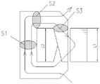
在图3所示的现有结构中,转子芯的各部的磁路剖面S1等于S2、S3远小于S2,转子芯轭部分的轴向长度L2等于定子铁芯的轴向长度L1,由于S3远小于S2,虽可以得到较大的磁场线圈的横截面面积,但爪状磁极部分的基部S3磁饱和,因此磁通量沿轴向泄漏,磁通量的泄漏导致到达定子铁芯的磁通量减少,而定子铁芯中减少的磁通量降低了发电机的电力输出。 In the existing structure shown in Figure 3, the magnetic circuit section S1 of each part of the rotor core is equal to S2, and S3 is much smaller than S2, and the axial length L2 of the yoke part of the rotor core is equal to the axial length L1 of the stator core. Smaller than S2, although a larger cross-sectional area of the magnetic field coil can be obtained, but the base S3 of the claw-shaped magnetic pole part is magnetically saturated, so the magnetic flux leaks along the axial direction, and the leakage of the magnetic flux leads to a decrease in the magnetic flux reaching the stator core, while the stator core The reduced magnetic flux in the generator reduces the electrical output of the generator.
在图4所示的现有结构中,转子芯的各部的磁路剖面S1、S2、S3优选为基本相同,转子芯轭部分的轴向长度L2小于定子铁芯的轴向长度L1,并且轭铁部分和定子铁芯相对,部分磁通量直接由轭铁部分流向定子铁芯,这虽然增加了流向定子铁芯的磁通,但磁路剖面S1、S2、S3基本相等,使得增强线圈“AT”仍然比较困难。 In the existing structure shown in Fig. 4, the magnetic circuit sections S1, S2, S3 of each part of the rotor core are preferably substantially the same, the axial length L2 of the yoke part of the rotor core is smaller than the axial length L1 of the stator core, and the yoke The iron part is opposite to the stator core, and part of the magnetic flux flows directly from the yoke part to the stator core. Although this increases the magnetic flux flowing to the stator core, the magnetic circuit sections S1, S2, and S3 are basically equal, making the enhanced coil "AT" Still relatively difficult.
在图5所示的现有结构中,转子芯各部的磁路剖面S1等于S2、S3远小于S2,转子芯轭部分的轴向长度L2小于定子铁芯的轴向长度L1,由于S3远小于S2,可以得到较大的磁场线圈的横截面面积,但爪状磁极部分的基部磁饱和。因此,尽管部分磁通量可以直接由轭铁部分流向定子铁芯,但是爪状磁极部分的基部的磁阻突然增大,从而使得流向定子铁芯的磁通总量明显受到限制。 In the existing structure shown in Figure 5, the magnetic circuit section S1 of each part of the rotor core is equal to S2, and S3 is much smaller than S2, and the axial length L2 of the yoke part of the rotor core is smaller than the axial length L1 of the stator core. Since S3 is much smaller than S2, a larger cross-sectional area of the magnetic field coil can be obtained, but the base of the claw-shaped magnetic pole part is magnetically saturated. Therefore, although part of the magnetic flux can flow directly from the yoke portion to the stator core, the reluctance at the base of the claw-shaped pole portion suddenly increases, so that the total amount of magnetic flux flowing to the stator core is significantly restricted.
在图6所示的现有结构中,转子芯的各部的磁路剖面S1等于S2、S3等于S2的0.47~0.8(由X1/X2=0.5~0.9换算得出),转子芯轭部分的轴向长度L2小于定子铁芯的轴向长度L1,同样由于S3大大小于S2,虽然可以得到较大的磁场线圈的横截面面积,但爪状磁极部分的基部仍趋于磁饱和。因此,尽管部分磁通量可以直接由轭铁部分流向定子铁芯,但是爪状磁极部分的基部的磁阻仍然很大,导致流向定子铁芯的磁通总量降低。 In the existing structure shown in Figure 6, the magnetic circuit section S1 of each part of the rotor core is equal to S2, and S3 is equal to 0.47~0.8 of S2 (converted from X 1 /X 2 =0.5~0.9), the rotor core yoke part The axial length L2 of the stator core is smaller than the axial length L1 of the stator core. Also because S3 is much smaller than S2, although a larger cross-sectional area of the magnetic field coil can be obtained, the base of the claw-shaped magnetic pole part still tends to be magnetically saturated. Therefore, although part of the magnetic flux can flow directly from the yoke portion to the stator core, the reluctance at the base of the claw pole portion is still large, resulting in a reduction in the total amount of magnetic flux flowing to the stator core.
在现有的磁场线圈空间中,提高磁场线圈“AT”,如磁场电流增大,磁场线圈产生的热量增加,因此造成对其冷却的困难,产生励磁损失增加,降低电力输出效率。为此,有以下方法,即利用自融电线、使用高导热性树脂线圈架等,改善励磁线圈的冷却特性。 In the existing field coil space, if the field coil "AT" is increased, if the field current increases, the heat generated by the field coil will increase, thus causing difficulty in cooling it, resulting in increased excitation loss and reduced power output efficiency. For this purpose, there are methods of improving the cooling characteristics of the field coil by using self-melting wires, using high thermal conductivity resin bobbins, and the like.
另外,还有采用不改变转子芯的尺寸和形状,减小空气间隙或增大定子铁芯的方法,以减小空气间隙和定子铁芯的磁阻为目的,但是,定子铁芯在整个磁阻中所占的比率小于转子芯,此外空气间隙的大小是根据机械方面的限制条件来决定,而不是根据转子和定子的工作精度、最高转速等电磁方面的限制条件,因此难以实现。 In addition, there are methods of reducing the air gap or increasing the stator core without changing the size and shape of the rotor core, in order to reduce the air gap and the reluctance of the stator core. However, the stator core is in the entire magnetic The proportion of resistance in the air gap is smaller than that of the rotor core. In addition, the size of the air gap is determined according to mechanical constraints, not electromagnetic constraints such as the working accuracy of the rotor and stator, the maximum speed, etc., so it is difficult to achieve.
还有,用一种磁铁插入爪状磁极部分之间的区域,以防止磁通量的泄漏,从而增加转子芯中的磁通量的总量。在这种情况中,由于使用磁铁和夹持磁铁的装置而造成成本提高,同时由于有离心力的作用,磁铁有可能在高转速下飞出原来的位置。 Also, a magnet is inserted into the region between the claw-shaped magnetic pole portions to prevent leakage of magnetic flux, thereby increasing the amount of magnetic flux in the rotor core. In this case, the cost increases due to the use of the magnet and the device for holding the magnet, and the magnet may fly out of its original position at high rotational speed due to the centrifugal force.
发明内容 Contents of the invention
鉴于上述存在的问题及转子芯和定子铁芯的磁路具有磁饱和的特性,并且发电机重量与定子铁芯的高度密切相关,与通过增大励磁线圈的空间来增加励磁线圈“AT”相比,本发明通过增大磁路的剖面来减小磁阻更能有效地增加流过定子铁芯的磁通量,采用转子芯轭部分的轴向长度L2小于定子铁芯的轴向长度L1并且适当限制定子铁芯的高度,同时,使用了转子芯各部分尺寸适当确定的设计,这些设计采用了协同效应,目的是为车辆提供一个结构紧凑的大电力发电机,其具有好的输出效能和低的成本。 In view of the above-mentioned problems and the magnetic circuit of the rotor core and the stator core has the characteristics of magnetic saturation, and the weight of the generator is closely related to the height of the stator core, it is comparable to increasing the field coil "AT" by increasing the space of the field coil Compared with that, the present invention reduces the reluctance by increasing the cross-section of the magnetic circuit and can effectively increase the magnetic flux flowing through the stator core, adopting the axial length L2 of the yoke part of the rotor core less than the axial length L1 of the stator core and appropriate The height of the stator core is limited, and at the same time, designs with properly dimensioned parts of the rotor core are used. These designs employ synergistic effects in order to provide vehicles with a compact, high-power generator with good output efficiency and low the cost of.
本发明解决上述技术问题的技术方案为:一种车辆用交流发电机,具有:励磁线圈、转子芯和定子铁芯;转子芯,其具有伦德尔型铁芯,该伦德尔型铁芯具有卷装该励磁线圈的轭部,该轭部呈圆筒状,从该轭部的轴方向位置向外周方向扩大的轭铁部,与该轭铁部连接并且形成为包围所述励磁线圈的爪状磁极部;定子铁芯,在转子芯爪状磁极部的外周对向配置,由层压铁芯和衔铁线圈构成;其特征在于:所述转子芯的轭部外半径设为R2,爪状磁极部分的外半径设为R3,R2/R3的比率为0.53~0.51;所述转子芯轭铁部的剖面设为S2,爪状磁极部的根部剖面设为S3,S3/S2的比率大于0.9,S3/S2的比率为0.90~0.98,所述定子铁芯的轴方向长度设为L1,转子芯轭部的长度设为L2,L1/L2的比率大于1。 The technical solution of the present invention to solve the above-mentioned technical problems is: an alternator for vehicles, which has: an excitation coil, a rotor core and a stator core; The yoke portion on which the field coil is mounted is cylindrical, and the yoke portion expanded from the axial position of the yoke portion to the outer peripheral direction is connected to the yoke portion and formed into a claw shape surrounding the field coil. The magnetic pole portion; the stator core is arranged opposite to the outer circumference of the claw-shaped magnetic pole portion of the rotor core, and is composed of a laminated iron core and an armature coil; it is characterized in that: the outer radius of the yoke of the rotor core is set to R 2 , and the claw-shaped The outer radius of the magnetic pole part is set as R 3 , and the ratio of R 2 /R 3 is 0.53 to 0.51; the section of the yoke part of the rotor core is set as S2, and the root section of the claw-shaped magnetic pole part is set as S3, S3/S2 The ratio is greater than 0.9, the ratio of S3/S2 is 0.90-0.98, the axial length of the stator core is L1, the length of the rotor core yoke is L2, and the ratio of L1/L2 is greater than 1.
上述L1/L2的比率更好为1.10~1.40,最好为1.26。 The above ratio of L1/L2 is more preferably from 1.10 to 1.40, most preferably 1.26.
在本发明中,R2/R3的比率为0.53~0.51,可以提供一个比现有结构更大的励磁线圈的横截面面积,使得在不增大磁场电流的情况下提供一个结构紧凑,高效能的发电机。 In the present invention, the ratio of R 2 /R 3 is 0.53 to 0.51, which can provide a larger cross-sectional area of the excitation coil than the existing structure, so that a compact structure and high efficiency can be provided without increasing the field current. capable generator.
在本发明中, S3/S2的比率为0.90~0.98,如0.93、0.95、0.97,爪状磁极部分的磁通量密度可以在一个最佳的范围内,同时,可以防止因S3过小而导致爪状磁极部分的磁饱和,降低发电机的电力输出。 In the present invention, the ratio of S3/S2 is 0.90~0.98, such as 0.93, 0.95, 0.97, the magnetic flux density of the claw-shaped magnetic pole part can be in an optimal range, and at the same time, it can prevent the claw-shaped magnetic flux density caused by too small S3. Magnetic saturation of the magnetic pole portion reduces the power output of the generator.
在本发明中, L1/L2的比率大于1,最好设为 1.10~1.40,如1.26。磁通量能够直接从轭铁部分流入定子铁芯。 In the present invention, the ratio of L1/L2 is greater than 1, preferably set to 1.10-1.40, such as 1.26. Magnetic flux can flow directly from the yoke portion into the stator core.
附图说明 Description of drawings
图1是按照本发明的车辆用交流发电机的主要部分剖面图。 Fig. 1 is a sectional view of a main part of an alternator for a vehicle according to the present invention.
图2是在现有结构中的定子铁芯和转子芯间流动的磁通量示意图,其中转子铁芯的S1=S2=S3;L1=L2。 Fig. 2 is a schematic diagram of the magnetic flux flowing between the stator core and the rotor core in the existing structure, wherein S1=S2=S3; L1=L2 of the rotor core.
图3是在现有结构中的定子铁芯和转子芯间流动的磁通量示意图,其中转子芯的S1=S2、S3〈S2;L1=L2。 Fig. 3 is a schematic diagram of the magnetic flux flowing between the stator core and the rotor core in the existing structure, wherein S1=S2, S3<S2; L1=L2 of the rotor core.
图4是在现有结构中的定子铁芯和转子芯间流动的磁通量示意图,其中转子芯的S1=S2=S3;L1〉L2。 Fig. 4 is a schematic diagram of the magnetic flux flowing between the stator core and the rotor core in the existing structure, wherein S1=S2=S3 of the rotor core; L1>L2.
图5是在现有结构中的定子铁芯和转子芯间流动的磁通量示意图,其中转子芯的S1=S2、S3〈S2;L1〉L2。 Fig. 5 is a schematic diagram of the magnetic flux flowing between the stator core and the rotor core in the existing structure, wherein S1=S2, S3<S2; L1>L2 of the rotor core.
图6是在现有结构中的定子铁芯和转子芯间流动的磁通量示意图,其中转子芯的S1=S2、S3=0.47S2~0.80S2;L1〉L2。 Fig. 6 is a schematic diagram of the magnetic flux flowing between the stator core and the rotor core in the existing structure, wherein S1=S2, S3=0.47S2-0.80S2 of the rotor core; L1>L2.
图7是按照本发明定子铁芯和转子芯的等效磁路示意图。 Fig. 7 is a schematic diagram of an equivalent magnetic circuit of a stator core and a rotor core according to the present invention.
图8是按照本发明车辆用交流发电机中转子芯的剖面图。 Fig. 8 is a sectional view of a rotor core in an alternator for a vehicle according to the present invention.
图9是图8从转子芯的圆柱部分方向看的视图。 FIG. 9 is a view of FIG. 8 viewed from the direction of the cylindrical portion of the rotor core.
图10是图8从转子芯的圆柱部分方向看的放大视图。 Fig. 10 is an enlarged view of Fig. 8 viewed from the direction of the cylindrical portion of the rotor core.
图11是S3/S2的比率为0.96时,每单位重量的发电机的电力输出和L1/L2比率之间关系的示意图。 Fig. 11 is a graph showing the relationship between the power output of the generator per unit weight and the L1/L2 ratio when the ratio of S3/S2 is 0.96.
图12是L1/L2的比率为1.26时,S3/S2的比率和磁阻大小之间关系的示意图。 FIG. 12 is a schematic diagram of the relationship between the ratio of S3/S2 and the magnitude of the magnetoresistance when the ratio of L1/L2 is 1.26.
图13是L1/L2的比率为1.26时,每单位重量的发电机的电力输出和S3/S2比率之间关系的示意图。 Fig. 13 is a graph showing the relationship between the power output of the generator per unit weight and the S3/S2 ratio when the ratio of L1/L2 is 1.26.
图14是R2/R3的比率为0.53时,每单位重量的发电机的电力输出和L1/L2比率之间关系的示意图。 FIG. 14 is a graph showing the relationship between the power output of the generator per unit weight and the L1/L2 ratio when the ratio of R2/R3 is 0.53.
图15是L1/L2的比率为1.26时,每单位重量的发电机的电力输出和R2/R3比率之间关系的示意图。 FIG. 15 is a graph showing the relationship between the power output of the generator per unit weight and the R2/R3 ratio when the ratio of L1/L2 is 1.26.
具体实施方式 Detailed ways
参见图1,按照本发明的一个实施例的一个车用发电机包括后壳、皮带轮、前轴承、后轴承、电刷、滑环、冷却风扇、整流器、轴、电压调节装置、励磁线圈、转子芯和定子铁芯。定子铁芯用作一个电枢,转子芯用于产生磁场,转子芯包括呈圆柱形的轭部分,轭铁部分以及爪状磁极部分,壳体支撑定子铁芯及转子芯,整流器直接与定子相连,整流器将交流电转换为直流电,电压调节装置调节磁场电流以控制产生的电力,电压调节装置中的晶体管和磁场线圈的高电压侧相连,从而当发电机不工作时,磁场线圈可以不承受电压。转子芯和轴一同转动,轴和一个皮带轮相连,并且向车辆发动机(未示出)提供动力驱动并旋转。 Referring to Fig. 1, according to an embodiment of the present invention, a vehicle generator comprises a rear shell, a pulley, a front bearing, a rear bearing, a brush, a slip ring, a cooling fan, a rectifier, a shaft, a voltage regulator, an exciting coil, and a rotor core and stator core. The stator core is used as an armature, and the rotor core is used to generate a magnetic field. The rotor core includes a cylindrical yoke part, a yoke part and a claw-shaped magnetic pole part. The casing supports the stator core and the rotor core. The rectifier is directly connected to the stator. , the rectifier converts alternating current to direct current, the voltage regulating device adjusts the field current to control the generated power, the transistor in the voltage regulating device is connected to the high voltage side of the field coil, so that when the generator is not working, the field coil can not bear the voltage. The rotor core rotates with the shaft, which is connected to a pulley and provides power to the vehicle engine (not shown) to drive and rotate.
下面参考图,对磁路进行详细的描述。转子芯的轭部外半径设为R2,爪状磁极部分的外半径设为R3;在将所述转子芯轭铁部的剖面设为S2,爪状磁极部的根部剖面设为S3;所述定子铁芯的轴方向长度设为L1,转子芯轭部的长度设为L2。 The magnetic circuit will be described in detail below with reference to the drawings. The outer radius of the yoke portion of the rotor core is set as R 2 , and the outer radius of the claw-shaped magnetic pole portion is set as R 3 ; the section of the yoke portion of the rotor core is set as S2, and the root section of the claw-shaped magnetic pole portion is set as S3; The axial length of the stator core is L1, and the length of the rotor core yoke is L2.
设转子芯磁极对数P为6对,X2=13.5mm,R3=50.15mm,发电机的空隙δ(定子铁芯2和转子芯3之间的空隙)等于通常所使用的值,即0.35mm,爪状磁极的结构为内径侧与外径侧相比出现等距缩小的情况下:
Assuming that the number of pole pairs P of the rotor core is 6 pairs, X 2 =13.5mm, R 3 =50.15mm, the gap δ of the generator (the gap between the
参考轭铁部分的横截面面积S2如下: The cross-sectional area S2 of the reference yoke portion is as follows:
S2=W·X2 S2=W·X 2
W=2Sin150·πR3/(2P) W=2Sin15 0 ·πR 3 /(2P)
其中“P”表示转子芯磁极对数 Where "P" represents the number of pole pairs of the rotor core
爪状磁极部根部的横截面面积S3如下: The cross-sectional area S3 of the root of the claw-shaped magnetic pole is as follows:
S3=π{R3 2 -(R3-X1)2}/(2P) S3=π{R 3 2 -(R 3 -X 1 ) 2 }/(2P)
当X1=0.5X2时,S3/S2=0.47 When X 1 =0.5X 2 , S3/S2=0.47
当X1=0.9X2时,S3/S2=0.80 When X 1 =0.9X 2 , S3/S2=0.80
当X1=X2时,S3/S2=0.90 When X 1 =X 2 , S3/S2=0.90
如前所述,R2/R3的比率小于0.54,如0.53;可以提供一个比现有结构更大的励磁线圈的横截面面积,使得在不增大磁场电流的情况下提供一个结构紧凑且高效能的发电机。 As mentioned above, the ratio of R 2 /R 3 is less than 0.54, such as 0.53; it can provide a larger cross-sectional area of the excitation coil than the existing structure, so that a compact structure and a High performance generator.
在本发明中,如图9所示,例如:转子芯的磁极对数为6时,爪状磁极剖面积的单侧缩小为15度,X1=X2时,S3/S2为0.9以上,定子铁芯外径D0为128mm,爪状磁极部分的R3等于50.15mm。 In the present invention, as shown in FIG. 9, for example: when the number of magnetic pole pairs of the rotor core is 6, one side of the claw-shaped magnetic pole cross-sectional area is reduced to 15 degrees, and when X 1 =X 2 , S3/S2 is 0.9 or more, The outer diameter D 0 of the stator core is 128mm, and the R 3 of the claw-shaped magnetic pole part is equal to 50.15mm.
在本发明中,如图10所示,例如:转子芯的磁极对数为6时,爪状磁极剖面积的单侧小于15度时,S3/S2为0.9以上,定子铁芯外径为128mm,爪状磁极部分的R3等于50.15mm。 In the present invention, as shown in Fig. 10, for example: when the number of magnetic pole pairs of the rotor core is 6, when the cross-sectional area of the claw-shaped magnetic pole is less than 15 degrees on one side, S3/S2 is 0.9 or more, and the outer diameter of the stator core is 128mm , R 3 of the claw pole part is equal to 50.15mm.
在本发明中,S3/S2的比率大于0.9,S3/S2的比率最好设为0.90~0.98,如0.93、0.95、0.97,这样爪状磁极部分的磁通量密度可以在一个最佳的范围内,同时,可以防止因S3过小而导致爪状磁极部分的磁饱和,降低发电机的电力输出。 In the present invention, the ratio of S3/S2 is greater than 0.9, and the ratio of S3/S2 is preferably set to 0.90~0.98, such as 0.93, 0.95, 0.97, so that the magnetic flux density of the claw-shaped magnetic pole part can be in an optimal range, At the same time, it can prevent the magnetic saturation of the claw-shaped magnetic pole part due to too small S3, and reduce the power output of the generator.
在本发明中,L1/L2的比率大于1,最好为 1.10~1.40,如1.26,磁通量能够直接从轭铁部分流入定子铁芯,并且不使定子铁芯过长而加大发电机的重量,影响每单位重量的发电机电力输出。 In the present invention, the ratio of L1/L2 is greater than 1, preferably 1.10-1.40, such as 1.26, the magnetic flux can flow directly from the yoke part into the stator core, and the stator core will not be too long to increase the weight of the generator , affecting the electrical output of the generator per unit weight.
图10是图8从转子芯的圆柱部分方向看的放大视图,所述爪状磁极剖面积的单侧缩小为a,通过a的改变来改变S3。 Fig. 10 is an enlarged view of Fig. 8 viewed from the direction of the cylindrical part of the rotor core. The cross-sectional area of the claw-shaped magnetic pole is reduced to a on one side, and S3 is changed by changing a.
上述爪状磁极剖面积的单侧缩小优先为小于15度,最好为0。 The unilateral reduction of the cross-sectional area of the claw-shaped magnetic poles is preferably less than 15 degrees, preferably 0.
本发明实施例的优点通过实验而得以证明。图12表示S3/S2与合成磁阻R的关系和实验结果,当S3/S2比率和L1/L2比率作为参数变化时,纵坐标表示合成磁阻R,横坐标表示S3/S2比率。可以充分地看出,通过扩大S3,合成磁阻R会大幅减少。特别是,L1/L2为1.26时效果明显。这表示,经过S3流入并且从爪状磁极部经过空隙流入定子的磁通量Φ1的爪状磁极部的磁阻极高,通过增加S3可有效地缓和此处的磁阻。如图所示将S3/S2设为0.9以上,就能够将合成磁阻R减少约 5%以上。再者L1/L2为1.26时即S3/S2为1.0时,磁阻可减少约 10%,因此能够提供磁通量增大并且输出高的交流发电机。 The advantages of the embodiments of the present invention are demonstrated through experiments. Figure 12 shows the relationship between S3/S2 and synthetic reluctance R and the experimental results. When the S3/S2 ratio and L1/L2 ratio are changed as parameters, the ordinate represents the synthetic reluctance R, and the abscissa represents the S3/S2 ratio. It can be seen sufficiently that by enlarging S3, the resultant reluctance R is greatly reduced. In particular, the effect is remarkable when L1/L2 is 1.26. This means that the reluctance of the claw-shaped magnetic pole portion of the magnetic flux Φ1 flowing through S3 and flowing from the claw-shaped magnetic pole portion into the stator through the gap is extremely high, and the reluctance here can be effectively alleviated by increasing S3. Setting S3/S2 to 0.9 or more as shown in the figure can reduce the combined reluctance R by about 5% or more. Furthermore, when L1/L2 is 1.26, that is, when S3/S2 is 1.0, the reluctance can be reduced by about 10%, so it is possible to provide an alternator with increased magnetic flux and high output.
在图11中,纵坐标表示每单位重量的发电机电力输出。实验结果显示,当S3/S2等于0.96时,每单位重量的发电机电力输出和L1/L2比率之间的关系。 In FIG. 11 , the ordinate represents the power output of the generator per unit weight. Experimental results show the relationship between generator power output per unit weight and L1/L2 ratio when S3/S2 is equal to 0.96.
在图13中,纵坐标表示每单位重量的发电机电力输出。实验结果显示,当L1/L2比率为1.26时,每单位重量的发电机电力输出和S3/S2比率之间的关系。 In FIG. 13 , the ordinate represents the power output of the generator per unit weight. The experimental results show the relationship between the generator power output per unit weight and the S3/S2 ratio when the L1/L2 ratio is 1.26.
在图14中,纵坐标表示每单位重量的发电机电力输出。实验结果显示,当R2/R3等于0.53,每单位重量的发电机电力输出和L1/L2比率之间的关系。 In FIG. 14, the ordinate represents the power output of the generator per unit weight. Experimental results show that when R 2 /R 3 is equal to 0.53, the relationship between the generator power output per unit weight and the L1/L2 ratio.
在图15中,纵坐标表示每单位重量的发电机电力输出。实验结果显示,当L1/L2比率为1.26时,每单位重量的发电机电力输出和R2/R3比率之间的关系。 In FIG. 15, the ordinate represents the power output of the generator per unit weight. The experimental results show the relationship between the generator power output per unit weight and the R2 / R3 ratio when the L1/L2 ratio is 1.26.
从图11至图16中充分说明,本发明选择的参数合理,均能保证每单位重量的发电机电力输出在31.5A/Kg以上。 It is fully illustrated from Fig. 11 to Fig. 16 that the selected parameters of the present invention are reasonable and can ensure that the power output of the generator per unit weight is above 31.5A/Kg.
在本发明的实施例中,定子铁芯外径为128mm,爪状磁极部分的R3等于50.15mm。即使当定子外径为139mm、144mm,也可得到同样好的结果。当爪状磁极部分的R3设置在50mm~60mm范围内时,本发明实施例的参数设置范围是有效的。当转子芯的磁极对数等于其它值,例如7或8时,也可得到同样好的结果。 In the embodiment of the present invention, the outer diameter of the stator core is 128 mm, and R 3 of the claw-shaped magnetic pole portion is equal to 50.15 mm. Even when the outer diameter of the stator is 139mm, 144mm, the same good result can be obtained. When R 3 of the claw-shaped magnetic pole part is set within the range of 50 mm to 60 mm, the parameter setting range of the embodiment of the present invention is effective. Equally good results are obtained when the number of pole pairs of the rotor core is equal to other values, such as 7 or 8.
Claims (5)
Priority Applications (1)
| Application Number | Priority Date | Filing Date | Title |
|---|---|---|---|
| CN2011104376195A CN102420472B (en) | 2011-12-23 | 2011-12-23 | Alternating current generator for vehicle |
Applications Claiming Priority (1)
| Application Number | Priority Date | Filing Date | Title |
|---|---|---|---|
| CN2011104376195A CN102420472B (en) | 2011-12-23 | 2011-12-23 | Alternating current generator for vehicle |
Publications (2)
| Publication Number | Publication Date |
|---|---|
| CN102420472A true CN102420472A (en) | 2012-04-18 |
| CN102420472B CN102420472B (en) | 2013-11-13 |
Family
ID=45944750
Family Applications (1)
| Application Number | Title | Priority Date | Filing Date |
|---|---|---|---|
| CN2011104376195A Expired - Fee Related CN102420472B (en) | 2011-12-23 | 2011-12-23 | Alternating current generator for vehicle |
Country Status (1)
| Country | Link |
|---|---|
| CN (1) | CN102420472B (en) |
Cited By (1)
| Publication number | Priority date | Publication date | Assignee | Title |
|---|---|---|---|---|
| CN104919686A (en) * | 2012-12-19 | 2015-09-16 | 罗伯特·博世有限公司 | Electric machine |
Citations (5)
| Publication number | Priority date | Publication date | Assignee | Title |
|---|---|---|---|---|
| JPH04255451A (en) * | 1991-02-06 | 1992-09-10 | Nippondenso Co Ltd | Ac generator for vehicle |
| US5536987A (en) * | 1993-11-29 | 1996-07-16 | Nippondenso Co., Ltd. | Alternating current generator for a motor vehicle |
| CN1152206A (en) * | 1995-08-11 | 1997-06-18 | 日本电装株式会社 | AC generator for vehicle |
| CN1162861A (en) * | 1995-11-02 | 1997-10-22 | 株式会社电装 | alternator for car |
| EP0910155A1 (en) * | 1997-09-26 | 1999-04-21 | Denso Corporation | Alternator for vehicle |
-
2011
- 2011-12-23 CN CN2011104376195A patent/CN102420472B/en not_active Expired - Fee Related
Patent Citations (5)
| Publication number | Priority date | Publication date | Assignee | Title |
|---|---|---|---|---|
| JPH04255451A (en) * | 1991-02-06 | 1992-09-10 | Nippondenso Co Ltd | Ac generator for vehicle |
| US5536987A (en) * | 1993-11-29 | 1996-07-16 | Nippondenso Co., Ltd. | Alternating current generator for a motor vehicle |
| CN1152206A (en) * | 1995-08-11 | 1997-06-18 | 日本电装株式会社 | AC generator for vehicle |
| CN1162861A (en) * | 1995-11-02 | 1997-10-22 | 株式会社电装 | alternator for car |
| EP0910155A1 (en) * | 1997-09-26 | 1999-04-21 | Denso Corporation | Alternator for vehicle |
Cited By (1)
| Publication number | Priority date | Publication date | Assignee | Title |
|---|---|---|---|---|
| CN104919686A (en) * | 2012-12-19 | 2015-09-16 | 罗伯特·博世有限公司 | Electric machine |
Also Published As
| Publication number | Publication date |
|---|---|
| CN102420472B (en) | 2013-11-13 |
Similar Documents
| Publication | Publication Date | Title |
|---|---|---|
| JP4410159B2 (en) | AC rotating electric machine | |
| KR101683494B1 (en) | Rotor structure of wrsm motor | |
| KR101382335B1 (en) | Rotor and synchronous motor having the same and wound rotor synchronous motor | |
| JP3186703B2 (en) | AC generator for vehicles | |
| JP2006516879A (en) | Trapezoidal motor magnetic pole device that increases magnetic flux to improve motor torque density | |
| JP2000156947A (en) | Magnet-type motor and power generator | |
| US7928616B2 (en) | Systems and apparatus involving toothed armatures in superconducting machines | |
| JP2009071924A (en) | Rotary electric machine | |
| JP2014220930A (en) | Magnet type rotary electrical machinery | |
| JP2008022630A (en) | Brushless alternator for vehicles | |
| WO2011067962A1 (en) | Vehicular rotating electric machine | |
| JP4788477B2 (en) | AC generator | |
| US9160218B2 (en) | Synchronous rotary electric machine having hybrid-excitation rotor | |
| JPH07298585A (en) | Alternator for vehicle | |
| JP2548882B2 (en) | Vehicle alternator | |
| JP2010098931A (en) | Motor | |
| CN102420472A (en) | Alternating current generator for vehicle | |
| US20130169095A1 (en) | Synchronous rotary electric machine having a double excitation rotor | |
| JP2007336723A (en) | Rotor for electric rotary machine | |
| CN109639035A (en) | Motor and the double-deck accumulated energy flywheel based on two-level rotor structure | |
| JPH08298736A (en) | Rotor with permanent magnet for magnet synchronous rotating machine | |
| JP2007028790A (en) | Vehicle dynamo-electric machine | |
| US9197118B2 (en) | Synchronous rotary electric machine having a hybrid-excitation rotor | |
| JP2002191157A (en) | Synchronous rotating electric machine with combined use of permanent magnet | |
| CN203166720U (en) | Alternating-current generator used for vehicle |
Legal Events
| Date | Code | Title | Description |
|---|---|---|---|
| C06 | Publication | ||
| PB01 | Publication | ||
| C10 | Entry into substantive examination | ||
| SE01 | Entry into force of request for substantive examination | ||
| ASS | Succession or assignment of patent right |
Owner name: NINGBO YUNSHENG AUTOMOBILE MOTOR SYSTEM CO., LTD. Free format text: FORMER OWNER: NINGBO YUNSHENG AUTO ELECTRIC INC. RIXING (NINGBO) MOTOR CO., LTD. Effective date: 20130711 |
|
| C41 | Transfer of patent application or patent right or utility model | ||
| TA01 | Transfer of patent application right |
Effective date of registration: 20130711 Address after: 315040 Zhejiang province Ningbo City Jiangdong District Road No. 348 Min'an Applicant after: NINGBO YUNSHENG Co.,Ltd. Applicant after: NINGBO YUNSHENG AUTO ELECTRIC Inc. Applicant after: Rixing (Ningbo) Motor Co.,Ltd. Address before: 315040 Zhejiang province Ningbo City Jiangdong District Road No. 348 Min'an Applicant before: NINGBO YUNSHENG Co.,Ltd. Applicant before: Ningbo Yunsheng Motor Co.,Ltd. Applicant before: Rixing (Ningbo) Motor Co.,Ltd. |
|
| C14 | Grant of patent or utility model | ||
| GR01 | Patent grant | ||
| CF01 | Termination of patent right due to non-payment of annual fee |
Granted publication date: 20131113 |
|
| CF01 | Termination of patent right due to non-payment of annual fee |