CN102415880B - Living body information detection circuit and blood-pressure meter - Google Patents
Living body information detection circuit and blood-pressure meter Download PDFInfo
- Publication number
- CN102415880B CN102415880B CN201110274960.3A CN201110274960A CN102415880B CN 102415880 B CN102415880 B CN 102415880B CN 201110274960 A CN201110274960 A CN 201110274960A CN 102415880 B CN102415880 B CN 102415880B
- Authority
- CN
- China
- Prior art keywords
- light
- pressure
- living body
- blood pressure
- body information
- Prior art date
- Legal status (The legal status is an assumption and is not a legal conclusion. Google has not performed a legal analysis and makes no representation as to the accuracy of the status listed.)
- Expired - Lifetime
Links
Images


Classifications
-
- A—HUMAN NECESSITIES
- A61—MEDICAL OR VETERINARY SCIENCE; HYGIENE
- A61B—DIAGNOSIS; SURGERY; IDENTIFICATION
- A61B5/00—Measuring for diagnostic purposes; Identification of persons
- A61B5/02—Detecting, measuring or recording for evaluating the cardiovascular system, e.g. pulse, heart rate, blood pressure or blood flow
-
- A—HUMAN NECESSITIES
- A61—MEDICAL OR VETERINARY SCIENCE; HYGIENE
- A61B—DIAGNOSIS; SURGERY; IDENTIFICATION
- A61B5/00—Measuring for diagnostic purposes; Identification of persons
- A61B5/68—Arrangements of detecting, measuring or recording means, e.g. sensors, in relation to patient
- A61B5/6801—Arrangements of detecting, measuring or recording means, e.g. sensors, in relation to patient specially adapted to be attached to or worn on the body surface
- A61B5/6813—Specially adapted to be attached to a specific body part
- A61B5/6814—Head
- A61B5/6815—Ear
- A61B5/6817—Ear canal
-
- A—HUMAN NECESSITIES
- A61—MEDICAL OR VETERINARY SCIENCE; HYGIENE
- A61B—DIAGNOSIS; SURGERY; IDENTIFICATION
- A61B5/00—Measuring for diagnostic purposes; Identification of persons
- A61B5/02—Detecting, measuring or recording for evaluating the cardiovascular system, e.g. pulse, heart rate, blood pressure or blood flow
- A61B5/021—Measuring pressure in heart or blood vessels
- A61B5/022—Measuring pressure in heart or blood vessels by applying pressure to close blood vessels, e.g. against the skin; Ophthalmodynamometers
- A61B5/02208—Measuring pressure in heart or blood vessels by applying pressure to close blood vessels, e.g. against the skin; Ophthalmodynamometers using the Korotkoff method
-
- A—HUMAN NECESSITIES
- A61—MEDICAL OR VETERINARY SCIENCE; HYGIENE
- A61B—DIAGNOSIS; SURGERY; IDENTIFICATION
- A61B5/00—Measuring for diagnostic purposes; Identification of persons
- A61B5/02—Detecting, measuring or recording for evaluating the cardiovascular system, e.g. pulse, heart rate, blood pressure or blood flow
- A61B5/021—Measuring pressure in heart or blood vessels
- A61B5/022—Measuring pressure in heart or blood vessels by applying pressure to close blood vessels, e.g. against the skin; Ophthalmodynamometers
- A61B5/02225—Measuring pressure in heart or blood vessels by applying pressure to close blood vessels, e.g. against the skin; Ophthalmodynamometers using the oscillometric method
-
- A—HUMAN NECESSITIES
- A61—MEDICAL OR VETERINARY SCIENCE; HYGIENE
- A61B—DIAGNOSIS; SURGERY; IDENTIFICATION
- A61B5/00—Measuring for diagnostic purposes; Identification of persons
- A61B5/68—Arrangements of detecting, measuring or recording means, e.g. sensors, in relation to patient
- A61B5/6801—Arrangements of detecting, measuring or recording means, e.g. sensors, in relation to patient specially adapted to be attached to or worn on the body surface
- A61B5/6813—Specially adapted to be attached to a specific body part
- A61B5/6814—Head
- A61B5/6815—Ear
- A61B5/6816—Ear lobe
-
- A—HUMAN NECESSITIES
- A61—MEDICAL OR VETERINARY SCIENCE; HYGIENE
- A61B—DIAGNOSIS; SURGERY; IDENTIFICATION
- A61B5/00—Measuring for diagnostic purposes; Identification of persons
- A61B5/68—Arrangements of detecting, measuring or recording means, e.g. sensors, in relation to patient
- A61B5/6801—Arrangements of detecting, measuring or recording means, e.g. sensors, in relation to patient specially adapted to be attached to or worn on the body surface
- A61B5/683—Means for maintaining contact with the body
- A61B5/6838—Clamps or clips
-
- A—HUMAN NECESSITIES
- A61—MEDICAL OR VETERINARY SCIENCE; HYGIENE
- A61B—DIAGNOSIS; SURGERY; IDENTIFICATION
- A61B2560/00—Constructional details of operational features of apparatus; Accessories for medical measuring apparatus
- A61B2560/04—Constructional details of apparatus
- A61B2560/0443—Modular apparatus
- A61B2560/045—Modular apparatus with a separable interface unit, e.g. for communication
-
- A—HUMAN NECESSITIES
- A61—MEDICAL OR VETERINARY SCIENCE; HYGIENE
- A61B—DIAGNOSIS; SURGERY; IDENTIFICATION
- A61B2562/00—Details of sensors; Constructional details of sensor housings or probes; Accessories for sensors
- A61B2562/02—Details of sensors specially adapted for in-vivo measurements
- A61B2562/0233—Special features of optical sensors or probes classified in A61B5/00
- A61B2562/0238—Optical sensor arrangements for performing transmission measurements on body tissue
-
- A—HUMAN NECESSITIES
- A61—MEDICAL OR VETERINARY SCIENCE; HYGIENE
- A61B—DIAGNOSIS; SURGERY; IDENTIFICATION
- A61B5/00—Measuring for diagnostic purposes; Identification of persons
- A61B5/0002—Remote monitoring of patients using telemetry, e.g. transmission of vital signals via a communication network
-
- A—HUMAN NECESSITIES
- A61—MEDICAL OR VETERINARY SCIENCE; HYGIENE
- A61B—DIAGNOSIS; SURGERY; IDENTIFICATION
- A61B5/00—Measuring for diagnostic purposes; Identification of persons
- A61B5/74—Details of notification to user or communication with user or patient; User input means
- A61B5/7405—Details of notification to user or communication with user or patient; User input means using sound
Landscapes
- Health & Medical Sciences (AREA)
- Life Sciences & Earth Sciences (AREA)
- Biomedical Technology (AREA)
- Molecular Biology (AREA)
- Veterinary Medicine (AREA)
- Physics & Mathematics (AREA)
- Public Health (AREA)
- Biophysics (AREA)
- Pathology (AREA)
- Engineering & Computer Science (AREA)
- General Health & Medical Sciences (AREA)
- Heart & Thoracic Surgery (AREA)
- Medical Informatics (AREA)
- Animal Behavior & Ethology (AREA)
- Surgery (AREA)
- Otolaryngology (AREA)
- Cardiology (AREA)
- Vascular Medicine (AREA)
- Physiology (AREA)
- Ophthalmology & Optometry (AREA)
- Measuring Pulse, Heart Rate, Blood Pressure Or Blood Flow (AREA)
- Measurement Of The Respiration, Hearing Ability, Form, And Blood Characteristics Of Living Organisms (AREA)
- Measuring And Recording Apparatus For Diagnosis (AREA)
Abstract
本发明提供了一种生物体信息检测电路,其特征在于,该生物体信息检测电路包括:发光元件,其向生物体的一部分照射光;受光元件,其接收所述照射光在生物体的一部分散射后的散射光,以检测脉波;遮光结构,其在所述受光元件的前面限制入射光在所述受光元件上的入射光角度。此外,还提供了一种生物体信息测量装置,其特征在于,该生物体信息测量装置包括:U字型臂,其夹紧耳部的一部分;压脉袋,其在该U字型臂的一个臂的内侧,对所述耳部的所述一部分施加压力;所述生物体信息检测电路,所述生物体信息检测电路内置在该压脉袋内。
The present invention provides a living body information detection circuit, which is characterized in that the living body information detection circuit includes: a light emitting element, which irradiates light to a part of the living body; a light receiving element, which receives the irradiated light on a part of the living body Scattered scattered light to detect the pulse wave; a light shielding structure, which limits the incident light angle of the incident light on the light receiving element in front of the light receiving element. In addition, a biological information measurement device is also provided, which is characterized in that the biological information measurement device includes: a U-shaped arm, which clamps a part of the ear; a cuff, which is placed on the U-shaped arm The inner side of one arm exerts pressure on the part of the ear; the biological information detection circuit is built in the cuff.
Description
本发明是申请号为201010261413.7、申请日为2004年10月6日、发明名称为“生物体信息检测电路和生物体信息测量装置”的中国发明专利申请的分案申请。The present invention is a divisional application of the Chinese invention patent application with the application number 201010261413.7, the application date is October 6, 2004, and the invention title is "biological information detection circuit and biological information measuring device".
分案所针对的申请是申请号为200480025617.3(PCT/JP2004/014759)、申请日为2004年10月6日、发明名称为“生物体信息检测装置和血压计”的中国发明专利申请的分案申请。The application targeted by the divisional case is a divisional case of a Chinese invention patent application with the application number 200480025617.3 (PCT/JP2004/014759), the filing date is October 6, 2004, and the invention title is "biological information detection device and sphygmomanometer" Apply.
技术领域 technical field
本发明涉及一种用于在耳部检测生物体信息的装置。The invention relates to a device for detecting biological information in the ear.
背景技术 Background technique
随着高龄化的推进,应对成人的生活习惯病已成为很大的社会性问题。特别地,在与高血压关联的疾患的情况下,已经认识到长期的血压数据采集非常重要。从这样的观点出发,开发了以血压为首的各种生物体信息的检测装置。With the advancement of aging, it has become a big social problem to deal with lifestyle-related diseases of adults. In particular, in the case of disorders associated with hypertension, long-term blood pressure data acquisition has been recognized to be of great importance. From such viewpoints, detection devices for various biological information including blood pressure have been developed.
在现有的在外耳部测量生物体信息的技术中,具有插入外耳道或外耳中的其它部位进行长时间佩戴的患者监视装置(例如,参照专利文献1)。该装置根据照射到生物体内的红外光或可视光的散射光的受光量,来计算脉搏、脉波、心电、体温、动脉血氧饱和度、以及血压等。但是,该装置没有用于固定在耳朵上的单元、因而不能稳定地测量生物体信息。此外,也没有明示血压的具体测量方法。In the existing technology for measuring biological information in the outer ear, there is a patient monitoring device that is inserted into the external auditory canal or other parts of the outer ear and worn for a long time (for example, refer to Patent Document 1). This device calculates pulse, pulse wave, electrocardiogram, body temperature, arterial blood oxygen saturation, and blood pressure based on the amount of received infrared light or scattered light of visible light irradiated into the living body. However, this device has no unit for fixing to the ear, and thus cannot stably measure biological information. In addition, there is no specific measurement method for blood pressure.
此外,耳朵形成为复杂的形状(例如,参照非专利文献1),但是现有装置佩戴在外耳道或耳垂上。因此,很难固定在耳朵上。Also, the ear is formed in a complicated shape (for example, refer to Non-Patent Document 1), but existing devices are worn on the external auditory canal or the earlobe. Therefore, it is difficult to fix on the ear.
此外,作为戴在外耳道或耳垂上的装置,具有这样的紧急信息装置(例如,参照专利文献2),其包括无线通信单元,并具有动脉血氧饱和浓度传感器、体温传感器、心电传感器、脉波传感器。该装置将传感器部分插入外耳道,数据通信部兼用作在耳上的固定单元,但不能断言其一定能够稳定地佩戴。Also, as a device worn on the external auditory canal or earlobe, there is an emergency information device (for example, refer to Patent Document 2) that includes a wireless communication unit and has an arterial oxygen saturation sensor, body temperature sensor, electrocardiogram sensor, pulse wave sensor. In this device, the sensor part is inserted into the external auditory canal, and the data communication part also serves as a fixing unit on the ear, but it cannot be asserted that it can be worn stably.
另一方面,关于血压的测量,利用血管的脉动波形的血压测量装置(例如,参照非专利文献2),与利用作为其它方式的压脉袋振动法或容积补偿法等的血压测量装置(例如,参照非专利文献3)相比较,已经具有可高精度地测量血压的研究成果。On the other hand, regarding the measurement of blood pressure, a blood pressure measuring device using a pulsation waveform of a blood vessel (for example, refer to Non-Patent Document 2), and a blood pressure measuring device using a cuff vibration method or a volume compensation method as other methods (for example, , compared with non-patent literature 3), there have been research results that can measure blood pressure with high precision.
并且,在本发明中,耳廓的名称主要根据非专利文献1,耳廓软骨的名称根据非专利文献4。此外,作为与测量血压的装置关联的文献的一例,如专利文献3。In addition, in the present invention, the name of the auricle is mainly based on Non-Patent
专利文献1:日本专利特开平9-122083Patent Document 1: Japanese Patent Laid-Open No. 9-122083
专利文献2:日本专利特开平11-128174Patent Document 2: Japanese Patent Laid-Open No. 11-128174
专利文献3:日本专利公报特许第3531386号Patent Document 3: Japanese Patent Publication No. 3531386
非专利文献1:Sobotta图解人体解剖学第一卷(监译者:冈本道雄)、第126-127页,医学书院Non-Patent Document 1: Sobotta Illustrated Human Anatomy Volume 1 (Supervised Translator: Michio Okamoto), Page 126-127, School of Medicine
非专利文献2:Osamu Tochikubo,Yoshiyuki Kawaso,Eiji Miyajima,Masao Ishii:一种使用三角运算的用于精确测量血压的新的振动测量方法(A new poto-oscillometricmethod employing the delta-algorithm for accurate blood pressure measurement),《Hypertension学报》(Journal of Hyper tension)1997,第2卷,第148-151页,图1,图3。Non-Patent Document 2: Osamu Tochikubo, Yoshiyuki Kawaso, Eiji Miyajima, Masao Ishii: A new poto-oscillometric method employing the delta-algorithm for accurate blood pressure measurement ), "Journal of Hypertension" (Journal of Hypertension) 1997,
非专利文献3:山越宪一、户川达男:“生物体传感器与测量装置”日本ME学会编/ME教科书丛书A-1、39页至52页。Non-Patent Document 3: Kenichi Yamagoshi, Tatsuo Togawa: "Biological Sensors and Measuring Devices" Japan ME Society/ME Textbook Series A-1, pages 39 to 52.
非专利文献4:Sobotta图解人体解剖学第一卷(监译者:冈本道雄)、p.127(株)医学书院,1996年10月1日发行。Non-Patent Document 4: Sobotta Illustrated Human Anatomy Volume 1 (Supervised Translator: Michio Okamoto), p.127 (Co., Ltd.) Medical College, published on October 1, 1996.
非专利文献5:L.A.GEDDES,“血压的直接和间接测量”(The DIRECT andINDIRECT MEASURMENT of BLOOD PRESSURE),《中间出版年鉴》(YEAR BOOKMEDIAL PUBLISHERS),INC.第97页、图2-22。Non-patent literature 5: L.A.GEDDES, "The DIRECT and INDIRECT MEASURMENT of BLOOD PRESSURE", "YEAR BOOKMEDIAL PUBLISHERS", INC. Page 97, Figure 2-22.
发明内容 Contents of the invention
在血压测量等需要对生物体组织进行加压的测量中,由于容易混入由振动引起的噪声,因此,难以正确地测量脉波、血压值,如何稳定地测量血压已成为课题。此外,由于日常活动中的测量很难在始终佩戴血压计的状态下按一定间隔或连续地测量血压,因此,用于生物体信息检测的装置的保持方法也成为课题。In blood pressure measurement, which requires pressurization of living tissue, noise caused by vibration is likely to be mixed, so it is difficult to accurately measure pulse wave and blood pressure value, and how to measure blood pressure stably has become a problem. In addition, since it is difficult to measure blood pressure at regular intervals or continuously while wearing a sphygmomanometer all the time during daily activities, how to hold the device for detecting biological information is also a problem.
本申请的发明是为了解决上述课题而提出的,其目的在于提供一种在人体耳部测量生物体信息的装置。The invention of the present application was made to solve the above-mentioned problems, and an object thereof is to provide a device for measuring biological information in the ear of a human body.
所述课题通过这样的血压计加以解决,该血压计具有:压力施加部,其用于对耳部的一部分施加压力;检测部,其用于检测所述耳部的所述一部分处的脉波。The problem is solved by a blood pressure monitor including: a pressure applying unit for applying pressure to a part of an ear; and a detecting unit for detecting a pulse wave at the part of the ear. .
此外,本发明可以作为一种生物体信息采集装置来构成,其是在一部分上包含圆柱、圆锥、棱柱、棱锥、圆锥台或棱锥台构成的形状的生物信息采集装置,其特征在于,具有用于采集生物体信息的传感部。In addition, the present invention can be configured as a living body information collection device, which is a living body information collection device that partially includes a shape composed of a cylinder, a cone, a prism, a pyramid, a truncated cone, or a truncated pyramid, and is characterized in that it has a Sensing unit for collecting biological information.
此外,本发明可以作为一种血压计来构成,其包括:架体部,其具有相互对置的第一臂和第二臂;压力施加部,其配置在下述两个位置中的至少一个位置上,第一臂的与该第二臂对置的一侧、或者该第二臂的与该第一臂对置的一侧;检测部,其用于检测脉波。In addition, the present invention can be configured as a blood pressure monitor including: a frame body having a first arm and a second arm opposed to each other; and a pressure applying unit arranged at at least one of the following two positions On the side of the first arm that is opposite to the second arm, or the side of the second arm that is opposite to the first arm; a detection unit for detecting pulse waves.
此外,本发明也可以作为生物体信息检测装置构成,其是在人体的耳廓检测生物体信息的生物体信息检测装置,具有沿着耳甲艇周围的耳廓软骨的形状。In addition, the present invention can also be configured as a biological information detection device that detects biological information on the auricle of a human body, and has a shape along the auricle cartilage around the concha concha.
另外,本发明也可以作为生物体信息检测装置构成,其包括:一对臂,它们相互对置;支轴,其在所述一对臂的各自的一端连接所述一对臂;距离可变机构,其设置在所述支轴上,用于调整所述一对臂的另一端之间的间隔;检测部,其安装在所述一对臂中的至少一个臂的另一端的、所述一对臂的彼此对置的一侧,用于检测生物体信息。In addition, the present invention can also be constituted as a living body information detection device including: a pair of arms facing each other; a support shaft connecting the pair of arms at respective one ends of the pair of arms; a variable distance a mechanism provided on the fulcrum for adjusting the distance between the other ends of the pair of arms; a detection unit mounted on the other end of at least one of the pair of arms, the The opposite sides of the pair of arms are used to detect biological information.
此外,根据本发明可以提供一种压脉袋,该压脉袋具有:基体,其由非伸缩部件构成;伸缩部件,其设置在该基体的单面上;以及空气供给管,该压脉袋通过从所述空气供给管提供空气来使所述伸缩部件的按压面只向基体的单面侧突出。Furthermore, according to the present invention, it is possible to provide a cuff having: a base composed of a non-stretchable member; a stretchable member provided on one side of the base; and an air supply tube, the cuff The pressing surface of the telescopic member protrudes only to one side of the base by supplying air from the air supply pipe.
另外,根据本发明还可以提供一种生物体信息检测电路,其包括:发光元件,其向生物体的一部分照射光;受光元件,其接收所述照射光在生物体的一部分上散射后的散射光,以检测脉波;以及遮光结构。In addition, according to the present invention, there may be provided a living body information detection circuit including: a light emitting element that irradiates light to a part of the living body; light to detect the pulse wave; and a light-shielding structure.
根据本发明还可以提供一种生物体信息检测电路生物体信息测量装置,该生物体信息测量装置包括:U字形臂,其夹紧耳部的一部分;压脉袋,其在该U字形臂的一个臂的内侧,对所述耳部的所述一部分施加压力;上述生物体信息检测电路,所述生物体信息检测电路内置在该压脉袋内。According to the present invention, there is also provided a living body information detection circuit living body information measuring device, which includes: a U-shaped arm, which clamps a part of the ear; a cuff, which is placed on the U-shaped arm. The inner side of one arm applies pressure to the part of the ear; the biological information detection circuit is built in the cuff.
通过参照附图及阅读以下的详细说明,可进一步明确本申请的发明的其它目的、特征、效果。Other objects, features, and effects of the invention of the present application will become clearer by reading the following detailed description with reference to the attached drawings.
根据本发明,可以提供一种测量适合在人体耳部进行测量的生物体信息的装置。此外,通过构成为包括压力施加部,可以提供特别适合血压测量的装置。According to the present invention, it is possible to provide a device for measuring biological information suitable for measurement in the ear of a human body. Furthermore, by including the pressure applying part, it is possible to provide a device particularly suitable for blood pressure measurement.
附图说明 Description of drawings
图1是表示本发明实施方式1-1的生物体信息采集装置的结构图。FIG. 1 is a configuration diagram showing a living body information collection device according to Embodiment 1-1 of the present invention.
图2是用于说明本发明实施方式1-1的生物体信息采集装置的保持部的制作方法的图。Fig. 2 is a diagram for explaining a method of manufacturing a holding portion of the living body information collection device according to Embodiment 1-1 of the present invention.
图3是用于说明本发明实施方式1-1的生物体信息采集装置佩戴于生物体的示例的图。3 is a diagram for explaining an example in which the living body information collection device according to Embodiment 1-1 of the present invention is worn on a living body.
图4是表示本发明实施方式1的生物体信息采集装置的其它结构的图。4 is a diagram showing another configuration of the living body information collection device according to
图5是表示本发明实施方式1-2的生物体信息采集装置的结构图。Fig. 5 is a configuration diagram showing a living body information collection device according to Embodiment 1-2 of the present invention.
图6是表示本发明实施方式1-3的生物体信息采集装置的结构图。Fig. 6 is a configuration diagram showing a living body information collection device according to Embodiment 1-3 of the present invention.
图7是表示本发明实施方式1-3的生物体信息采集装置的结构图。Fig. 7 is a configuration diagram showing a living body information collection device according to Embodiment 1-3 of the present invention.
图8是用于说明本发明实施方式1-3的生物体信息采集装置佩戴于生物体的示例的图。FIG. 8 is a diagram for explaining an example in which the living body information collection device according to Embodiment 1-3 of the present invention is worn on a living body.
图9是表示本发明实施方式1-4的生物体信息采集装置的结构图。Fig. 9 is a configuration diagram showing a living body information collection device according to Embodiment 1-4 of the present invention.
图10是用于说明本发明实施方式1-4的生物体信息采集装置佩戴于生物体的示例的图。FIG. 10 is a diagram for explaining an example in which the living body information collection device according to Embodiment 1-4 of the present invention is worn on a living body.
图11是表示本发明实施方式1-5的生物体信息采集装置的结构图。Fig. 11 is a configuration diagram showing a living body information collection device according to Embodiment 1-5 of the present invention.
图12是表示本发明实施方式1-6的生物体信息采集装置的结构图。Fig. 12 is a configuration diagram showing a living body information collection device according to Embodiment 1-6 of the present invention.
图13是表示本发明实施方式1-7的生物体信息采集装置的结构图。Fig. 13 is a configuration diagram showing a living body information collection device according to Embodiment 1-7 of the present invention.
图14是用于说明血压测量的原理1的图。FIG. 14 is a diagram for explaining
图15是用于说明血压测量的原理1的图。FIG. 15 is a diagram for explaining
图16是现有血压测量装置的结构图。Fig. 16 is a block diagram of a conventional blood pressure measuring device.
图17是用于说明血压测量的原理2的图。FIG. 17 is a diagram for explaining
图18是表示生物体信息采集的其它示例的图。FIG. 18 is a diagram showing another example of biometric information collection.
图19是表示本发明实施方式1-8的生物体信息采集系统的结构图。Fig. 19 is a configuration diagram showing a living body information collection system according to Embodiment 1-8 of the present invention.
图20是表示本发明实施方式1-9的生物体信息采集系统的结构图。Fig. 20 is a configuration diagram showing a living body information collection system according to Embodiment 1-9 of the present invention.
图21是表示本发明实施方式1-10和实施方式1-11的生物体信息采集系统的结构图。Fig. 21 is a configuration diagram showing the living body information collection system of Embodiment 1-10 and Embodiment 1-11 of the present invention.
图22是表示本发明实施方式1-12的生物体信息采集系统的结构图。Fig. 22 is a configuration diagram showing a living body information collection system according to Embodiment 1-12 of the present invention.
图23是表示本发明实施方式1-13的生物体信息采集系统的结构图。Fig. 23 is a configuration diagram showing a living body information collection system according to Embodiment 1-13 of the present invention.
图24是用于说明本发明实施方式1-13的生物体信息采集系统的安装以及佩戴于生物体的示例的图。Fig. 24 is a diagram for explaining an example in which the living body information collection system according to the first to thirteenth embodiment of the present invention is installed and worn on a living body.
图25是表示本发明实施方式中的生物体信息采集装置的保持部的安装示例的图。Fig. 25 is a diagram showing an example of attachment of the holding unit of the living body information collection device according to the embodiment of the present invention.
图26是表示本发明实施方式2-1中的血压计的结构图。Fig. 26 is a configuration diagram showing the blood pressure meter in Embodiment 2-1 of the present invention.
图27是用于详细说明在本发明实施方式2-1中,利用血压测量的原理1进行血压测量的图。Fig. 27 is a diagram illustrating in detail blood pressure
图28是表示本发明实施方式2-2中的血压计的结构图。Fig. 28 is a configuration diagram showing a blood pressure meter in Embodiment 2-2 of the present invention.
图29是表示本发明实施方式2-3中的血压计的结构图。Fig. 29 is a configuration diagram showing a blood pressure meter in Embodiment 2-3 of the present invention.
图30是表示本发明实施方式2-4中的血压计的结构图。Fig. 30 is a configuration diagram showing a sphygmomanometer in Embodiment 2-4 of the present invention.
图31是表示本发明实施方式2-4中的血压计的结构图。Fig. 31 is a configuration diagram showing a sphygmomanometer in Embodiment 2-4 of the present invention.
图32是表示本发明实施方式2-4中的血压计的结构图。Fig. 32 is a configuration diagram showing a sphygmomanometer in Embodiment 2-4 of the present invention.
图33是表示本发明实施方式2-5中的血压计的结构图。Fig. 33 is a configuration diagram showing a blood pressure meter in Embodiment 2-5 of the present invention.
图34是表示本发明实施方式2-6中的血压计的结构图。Fig. 34 is a configuration diagram showing a sphygmomanometer in Embodiment 2-6 of the present invention.
图35是表示本发明实施方式2-6中的血压计的结构图。Fig. 35 is a configuration diagram showing a sphygmomanometer in Embodiment 2-6 of the present invention.
图36是表示本发明实施方式2-7中的血压计的结构图。Fig. 36 is a configuration diagram showing a sphygmomanometer in Embodiment 2-7 of the present invention.
图37是表示本发明实施方式2-8中的血压计的结构图。Fig. 37 is a configuration diagram showing a sphygmomanometer in Embodiment 2-8 of the present invention.
图38是表示本发明实施方式2-9中的血压计的结构图。Fig. 38 is a configuration diagram showing a sphygmomanometer in Embodiment 2-9 of the present invention.
图39是表示本发明实施方式2-10中的血压计的结构图。Fig. 39 is a configuration diagram showing a blood pressure monitor in Embodiment 2-10 of the present invention.
图40是表示本发明实施方式2-10中的血压计的结构图。Fig. 40 is a configuration diagram showing a blood pressure monitor in Embodiment 2-10 of the present invention.
图41是表示本发明实施方式2-11中的血压计的结构图。Fig. 41 is a configuration diagram showing a sphygmomanometer in Embodiment 2-11 of the present invention.
图42是表示本发明实施方式2-11中的血压计的结构图。Fig. 42 is a configuration diagram showing a blood pressure meter in Embodiment 2-11 of the present invention.
图43是表示本发明实施方式2-12中的血压计的结构图。Fig. 43 is a configuration diagram showing a sphygmomanometer in Embodiment 2-12 of the present invention.
图44是表示本发明实施方式2-12中的血压计的结构图。Fig. 44 is a configuration diagram showing a sphygmomanometer in Embodiment 2-12 of the present invention.
图45是表示本发明实施方式2-13中的血压计的结构图。Fig. 45 is a configuration diagram showing a blood pressure meter in Embodiment 2-13 of the present invention.
图46是表示本发明实施方式2-13中的血压计的结构图。Fig. 46 is a configuration diagram showing a blood pressure meter in Embodiment 2-13 of the present invention.
图47是表示本发明实施方式2-13中的血压计的结构图。Fig. 47 is a configuration diagram showing a blood pressure meter in Embodiment 2-13 of the present invention.
图48是表示在实施方式2-9的血压计中附加固定部4和固定调整部5后的结构图。Fig. 48 is a configuration diagram showing a sphygmomanometer according to Embodiment 2-9 in which a fixing
图49是表示在实施方式2-12的血压计中附加固定部4和固定调整部5后的结构图。Fig. 49 is a configuration diagram showing a sphygmomanometer according to Embodiment 2-12 in which a fixing
图50是表示在实施方式2-12的血压计中附加固定部4和固定调整部5后的结构图。Fig. 50 is a configuration diagram showing a configuration in which the fixing
图51是表示本发明实施方式2-15中的血压计的结构图。Fig. 51 is a configuration diagram showing a blood pressure monitor in Embodiment 2-15 of the present invention.
图52是表示本发明实施方式2-16中的血压计的结构图。Fig. 52 is a configuration diagram showing a blood pressure meter in Embodiment 2-16 of the present invention.
图53是表示实施方式2-16中的血压计佩戴于耳部的状态的图。Fig. 53 is a diagram showing a state in which the sphygmomanometer in Embodiment 2-16 is worn on the ear.
图54是表示本发明实施方式2-17中的血压计的结构图。Fig. 54 is a configuration diagram showing a blood pressure monitor in Embodiment 2-17 of the present invention.
图55是表示将悬架机构61安装到眼镜腿部62的示例的图。FIG. 55 is a diagram showing an example of attaching the
图56是表示将悬架机构61安装到眼镜腿部62的末端部分的示例的图。FIG. 56 is a diagram showing an example of attaching the
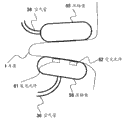
图57是表示耳廓的软骨结构和各部分名称的图。Fig. 57 is a diagram showing the cartilage structure of the auricle and the names of each part.
图58是表示耳廓的结构和各部分名称的图。Fig. 58 is a diagram showing the structure of the auricle and the names of each part.
图59是用于说明外耳的图。Fig. 59 is a diagram for explaining the outer ear.
图60是用于说明外耳周边的图。Fig. 60 is a diagram for explaining the periphery of the auricle.
图61是表示实施方式3的生物体信息检测装置的结构例的图。FIG. 61 is a diagram showing a configuration example of a living body information detection device according to
图62是表示实施方式3的生物体信息检测装置的结构例的图。FIG. 62 is a diagram showing a configuration example of a living body information detection device according to
图63是表示实施方式3的生物体信息检测装置的结构例的图。FIG. 63 is a diagram showing a configuration example of a living body information detection device according to
图64是表示实施方式3的生物体信息检测装置的结构例的图。FIG. 64 is a diagram showing a configuration example of a living body information detection device according to
图65是表示实施方式3的生物体信息检测装置的结构例的图。FIG. 65 is a diagram showing a configuration example of a living body information detection device according to
图66是表示实施方式3的生物体信息检测装置的结构例的图。FIG. 66 is a diagram showing a configuration example of a living body information detection device according to
图67是使用发光元件和受光元件的脉波检测原理的说明图。Fig. 67 is an explanatory diagram of the principle of pulse wave detection using a light-emitting element and a light-receiving element.
图68是表示实施方式3的可测量血压的生物体信息检测装置的结构例的图。FIG. 68 is a diagram showing a configuration example of a living body information detection device capable of measuring blood pressure according to
图69是表示实施方式3的可测量血压的生物体信息检测装置的结构例的图。FIG. 69 is a diagram showing a configuration example of a living body information detection device capable of measuring blood pressure according to
图70是表示实施方式3的可测量血压的生物体信息检测装置的结构例的图。FIG. 70 is a diagram showing a configuration example of a living body information detection device capable of measuring blood pressure according to
图71是表示实施方式3的可测量血压的生物体信息检测装置的结构例的图。71 is a diagram showing a configuration example of a living body information detection device capable of measuring blood pressure according to
图72是表示实施方式3的可测量血压的生物体信息检测装置的结构例的图。FIG. 72 is a diagram showing a configuration example of a living body information detection device capable of measuring blood pressure according to
图73是表示实施方式3的可测量血压的生物体信息检测装置的结构例的图。FIG. 73 is a diagram showing a configuration example of a living body information detection device capable of measuring blood pressure according to
图74是表示实施方式3的可测量血压的生物体信息检测装置的结构例的图。FIG. 74 is a diagram showing a configuration example of a living body information detection device capable of measuring blood pressure according to
图75是表示实施方式3的可测量血压的生物体信息检测装置的结构例的图。FIG. 75 is a diagram showing a configuration example of a living body information detection device capable of measuring blood pressure according to
图76是表示实施方式3的可测量血压的生物体信息检测装置的结构例的图。FIG. 76 is a diagram showing a configuration example of a living body information detection device capable of measuring blood pressure according to
图77是表示实施方式3的可测量血压的生物体信息检测装置的结构例的图。FIG. 77 is a diagram showing a configuration example of a living body information detection device capable of measuring blood pressure according to
图78是表示实施方式3的可测量血压的生物体信息检测装置的结构例的图。FIG. 78 is a diagram showing a configuration example of a living body information detection device capable of measuring blood pressure according to
图79是表示实施方式3的可测量血压的生物体信息检测装置的结构例的图。FIG. 79 is a diagram showing a configuration example of a living body information detection device capable of measuring blood pressure according to
图80是表示实施方式3的可测量血压的生物体信息检测装置的结构例的图。FIG. 80 is a diagram showing a configuration example of a living body information detection device capable of measuring blood pressure according to
图81是表示实施方式3的可测量血压的生物体信息检测装置的结构例的图。FIG. 81 is a diagram showing a configuration example of a living body information detection device capable of measuring blood pressure according to
图82是表示实施方式4的生物体信息检测装置的结构例的说明图。FIG. 82 is an explanatory diagram showing a configuration example of a living body information detection device according to
图83是表示实施方式4的生物体信息检测装置的结构例的说明图。FIG. 83 is an explanatory diagram showing a configuration example of a living body information detection device according to
图84是表示实施方式4的生物体信息检测装置的结构例的说明图。FIG. 84 is an explanatory diagram showing a configuration example of a living body information detection device according to
图85是表示实施方式4的生物体信息检测装置佩戴于耳廓的状态的说明图。Fig. 85 is an explanatory diagram showing a state in which the living body information detection device according to
图86是表示实施方式4的生物体信息检测装置的结构例的说明图。FIG. 86 is an explanatory diagram showing a configuration example of a living body information detection device according to
图87是表示实施方式4的生物体信息检测装置的结构例的说明图。FIG. 87 is an explanatory diagram showing a configuration example of a living body information detection device according to
图88是表示实施方式4的生物体信息检测装置的结构例的说明图。FIG. 88 is an explanatory diagram showing a configuration example of a living body information detection device according to
图89是表示实施方式4的生物体信息检测装置佩戴到耳廓的状态的说明图。FIG. 89 is an explanatory diagram showing a state where the living body information detection device according to
图90是表示实施方式4的生物体信息检测装置的结构例的说明图。FIG. 90 is an explanatory diagram showing a configuration example of a living body information detection device according to
图91是表示实施方式4的生物体信息检测装置的结构例与佩戴于耳廓的状态的说明图。FIG. 91 is an explanatory diagram showing a configuration example of a living body information detection device according to
图92是表示实施方式4的生物体信息检测装置的结构例与佩戴于耳廓的状态的说明图。FIG. 92 is an explanatory diagram showing a configuration example of a living body information detection device according to
图93是表示实施方式4的生物体信息检测装置的结构例与佩戴于耳廓的状态的说明图。FIG. 93 is an explanatory diagram showing a configuration example of a living body information detection device according to
图94是表示实施方式4的生物体信息检测装置的结构例的说明图。FIG. 94 is an explanatory diagram showing a configuration example of a living body information detection device according to
图95是表示实施方式4的生物体信息检测装置的结构例与佩戴于耳廓的状态的说明图。FIG. 95 is an explanatory diagram showing a configuration example of a living body information detection device according to
图96是表示实施方式4的生物体信息检测装置的结构例的说明图。FIG. 96 is an explanatory diagram showing a configuration example of a living body information detection device according to
图97是使用发光元件和受光元件进行脉搏检测的原理的说明图。Fig. 97 is an explanatory diagram of the principle of pulse detection using a light-emitting element and a light-receiving element.
图98是表示实施方式4的生物体信息检测装置的结构例与佩戴于耳廓的状态的说明图。FIG. 98 is an explanatory diagram showing a configuration example of a living body information detection device according to
图99是表示实施方式4的生物体信息检测装置的传感器部分佩戴于耳廓的状态的说明图。99 is an explanatory view showing a state where the sensor portion of the living body information detection device according to
图100是表示实施方式4的生物体信息检测装置的传感器部分佩戴于耳廓的状态的说明图。FIG. 100 is an explanatory diagram showing a state in which the sensor portion of the living body information detection device according to
图101是表示实施方式4的生物体信息检测装置的传感器部分佩戴于耳廓的状态的说明图。101 is an explanatory diagram showing a state where the sensor portion of the living body information detection device according to
图102是表示实施方式4的生物体信息检测装置的传感器部分佩戴于耳廓的状态的说明图。102 is an explanatory diagram showing a state where the sensor portion of the living body information detection device according to
图103是表示实施方式4的生物体信息检测装置的传感器部分佩戴于耳廓的状态的说明图。103 is an explanatory diagram showing a state where the sensor portion of the living body information detection device according to
图104是表示实施方式4的生物体信息检测装置的传感器部分佩戴于耳廓的状态的说明图。104 is an explanatory diagram showing a state where the sensor portion of the living body information detection device according to
图105是表示实施方式4的生物体信息检测装置的传感器部分佩戴于耳廓的状态的说明图。105 is an explanatory diagram showing a state where the sensor portion of the living body information detection device according to
图106是表示实施方式4的生物体信息检测装置的传感器部分佩戴于耳廓的状态的说明图。106 is an explanatory diagram showing a state where the sensor portion of the living body information detection device according to
图107是表示实施方式4的生物体信息检测装置的传感器部分佩戴于耳廓的状态的说明图。107 is an explanatory diagram showing a state where the sensor portion of the living body information detection device according to
图108是表示实施方式4的生物体信息检测装置的传感器部分佩戴于耳廓的状态的说明图。108 is an explanatory diagram showing a state where the sensor portion of the living body information detection device according to
图109是表示实施方式4的生物体信息检测装置的传感器部分佩戴于耳廓的状态的说明图。109 is an explanatory diagram showing a state where the sensor portion of the living body information detection device according to
图110是表示实施方式4的生物体信息检测装置的结构例的图。FIG. 110 is a diagram showing a configuration example of a living body information detection device according to
图111是表示实施方式4的生物体信息检测装置的结构例的图。FIG. 111 is a diagram showing a configuration example of a living body information detection device according to
图112是表示实施方式5的作为实施方式的压脉袋的结构的概略截面图。FIG. 112 is a schematic cross-sectional view showing the configuration of a cuff as an embodiment of
图113是表示实施方式5的压脉袋的结构的概略图,(A)是俯视图、(B)是沿俯视图(A)中的A-A′线的截面图。113 is a schematic diagram showing the structure of a cuff according to
图114是表示实施方式5的压脉袋的结构的概略图,(A)是俯视图、(B)是沿俯视图(A)中的A-A′线的截面图。114 is a schematic diagram showing the structure of a cuff according to
图115是表示实施方式5的压脉袋的结构和压脉袋按压生物体的过程的概略截面图。Fig. 115 is a schematic cross-sectional view showing the structure of the cuff according to
图116是表示实施方式5的压脉袋的结构和压脉袋按压生物体的过程的概略截面图。Fig. 116 is a schematic cross-sectional view showing the structure of the cuff according to
图117是表示实施方式5的压脉袋的结构和压脉袋按压生物体的过程的概略截面图。Fig. 117 is a schematic cross-sectional view showing the structure of the cuff according to
图118是表示实施方式5的压脉袋的结构的概略截面图。118 is a schematic cross-sectional view showing the structure of a cuff according to
图119是表示实施方式5的压脉袋的结构的概略截面图。FIG. 119 is a schematic cross-sectional view showing the structure of a cuff according to
图120是表示实施方式5的压脉袋的结构的概略截面图。FIG. 120 is a schematic cross-sectional view showing the structure of a cuff according to
图121是表示实施方式5的压脉袋的结构的概略截面图。FIG. 121 is a schematic cross-sectional view showing the structure of a cuff according to
图122是表示实施方式5的压脉袋的结构的概略截面图。122 is a schematic cross-sectional view showing the structure of a cuff according to
图123是表示实施方式5的压脉袋的结构的概略截面图。123 is a schematic cross-sectional view showing the structure of a cuff according to
图124是表示实施方式5的压脉袋的结构的概略截面图。124 is a schematic cross-sectional view showing the structure of a cuff according to
图125是表示实施方式5的压脉袋的结构的概略截面图。125 is a schematic cross-sectional view showing the structure of a cuff according to
图126是表示实施方式5的压脉袋的结构的概略截面图。126 is a schematic cross-sectional view showing the structure of a cuff according to
图127是表示实施方式5的压脉袋的结构的概略截面图。127 is a schematic cross-sectional view showing the structure of a cuff according to
图128是表示实施方式5的压脉袋的结构的概略截面图。128 is a schematic cross-sectional view showing the structure of a cuff according to
图129是表示实施方式5的压脉袋的结构的概略截面图。FIG. 129 is a schematic cross-sectional view showing the structure of a cuff according to
图130是表示实施方式5的压脉袋的结构的概略截面图。FIG. 130 is a schematic cross-sectional view showing the structure of a cuff according to
图131是表示实施方式5的压脉袋的结构的概略截面图。FIG. 131 is a schematic cross-sectional view showing the structure of a cuff according to
图132是表示实施方式5的压脉袋的结构的概略截面图。132 is a schematic cross-sectional view showing the structure of a cuff according to
图133是表示实施方式5的压脉袋的结构的概略截面图。FIG. 133 is a schematic cross-sectional view showing the structure of a cuff according to
图134是表示实施方式6的生物体信息检测电路和压脉袋的说明图。FIG. 134 is an explanatory diagram showing a living body information detection circuit and a cuff according to Embodiment 6. FIG.
图135是表示实施方式6的生物体信息检测电路和压脉袋的说明图。FIG. 135 is an explanatory diagram showing a living body information detection circuit and a cuff according to Embodiment 6. FIG.
图136是血压测量的原理的说明图。Fig. 136 is an explanatory diagram of the principle of blood pressure measurement.
图137是表示实施方式6的生物体信息检测电路和现有的生物体信息检测电路的脉动波形的检测例的说明图。137 is an explanatory diagram showing detection examples of pulsation waveforms by the living body information detection circuit according to the sixth embodiment and a conventional living body information detection circuit.
图138是表示实施方式6的生物体信息检测电路和压脉袋的说明图。FIG. 138 is an explanatory diagram showing a living body information detection circuit and a cuff according to Embodiment 6. FIG.
图139是表示实施方式6的生物体信息检测电路和压脉袋的说明图。FIG. 139 is an explanatory diagram showing a living body information detection circuit and a cuff according to Embodiment 6. FIG.
图140是表示实施方式6的生物体信息检测电路和压脉袋的说明图。FIG. 140 is an explanatory diagram showing a living body information detection circuit and a cuff according to Embodiment 6. FIG.
图141是表示实施方式6的生物体信息检测电路和压脉袋的说明图。FIG. 141 is an explanatory diagram showing a living body information detection circuit and a cuff according to Embodiment 6. FIG.
图142是表示实施方式6的生物体信息检测电路和压脉袋的说明图。FIG. 142 is an explanatory diagram showing a living body information detection circuit and a cuff according to Embodiment 6. FIG.
图143是表示实施方式6的生物体信息检测电路和压脉袋的说明图。FIG. 143 is an explanatory diagram showing a living body information detection circuit and a cuff according to Embodiment 6. FIG.
图144是表示实施方式6的生物体信息检测电路和压脉袋的说明图。FIG. 144 is an explanatory diagram showing a living body information detection circuit and a cuff according to Embodiment 6. FIG.
图145是表示实施方式6的生物体信息检测电路和压脉袋的说明图。FIG. 145 is an explanatory diagram showing a living body information detection circuit and a cuff according to Embodiment 6. FIG.
图146是表示实施方式6的生物体信息检测电路和压脉袋的说明图。FIG. 146 is an explanatory diagram showing a living body information detection circuit and a cuff according to Embodiment 6. FIG.
图147是表示实施方式6的生物体信息检测电路和压脉袋的说明图。FIG. 147 is an explanatory diagram showing a living body information detection circuit and a cuff according to Embodiment 6. FIG.
图148是表示实施方式6的生物体信息检测电路和压脉袋的说明图。FIG. 148 is an explanatory diagram showing a living body information detection circuit and a cuff according to Embodiment 6. FIG.
图149是表示实施方式6的生物体信息检测电路和压脉袋的说明图。FIG. 149 is an explanatory diagram showing a living body information detection circuit and a cuff according to Embodiment 6. FIG.
图150是用于说明实施方式6的血压测量的图。FIG. 150 is a diagram for explaining blood pressure measurement in Embodiment 6. FIG.
图151是用于说明实施方式6的血压测量的图。FIG. 151 is a diagram for explaining blood pressure measurement in Embodiment 6. FIG.
图152是用于说明实施方式6的血压测量的图。FIG. 152 is a diagram for explaining blood pressure measurement in Embodiment 6. FIG.
图153是用于说明实施方式6的血压测量的图。FIG. 153 is a diagram for explaining blood pressure measurement in Embodiment 6. FIG.
图154是实施方式7中的生物体信息检测装置的主体部的结构图。FIG. 154 is a configuration diagram of a main body of a living body information detection device in Embodiment 7. FIG.
标号说明Label description
(实施方式1)(Embodiment 1)
1:架体;2:保持部;3:传感部;4:驱动控制部;5:发送部;6:电源部;7:悬架部;8:移动终端;9:终端接收部;10:显示部;11:通信部;12:终端接收部;13:接收部;14:声音部;15:收发部;16:信号线;17:压力供给管;18:声音部悬架部;19:切削部分;20:发光元件;21:受光元件;22:压力产生机构;23:压力检测机构;30:血压传感器;31:体温传感器;32:脉搏传感器;33:体位传感器;34:加速度传感器;35:血氧浓度传感器;36:脑波传感器;37:信号线;40:耳廓;41:外耳;42:外耳道;50:信息处理装置;51:通信网;52:天线。1: frame body; 2: holding part; 3: sensing part; 4: drive control part; 5: sending part; 6: power supply part; 7: suspension part; 8: mobile terminal; 9: terminal receiving part; 10 : display part; 11: communication part; 12: terminal receiving part; 13: receiving part; 14: sound part; 15: sending and receiving part; 16: signal line; 17: pressure supply pipe; 18: sound part suspension part; 19 : cutting part; 20: light emitting element; 21: light receiving element; 22: pressure generating mechanism; 23: pressure detecting mechanism; 30: blood pressure sensor; 31: body temperature sensor; 32: pulse sensor; 33: body position sensor; 34: acceleration sensor 35: blood oxygen concentration sensor; 36: brain wave sensor; 37: signal line; 40: pinna; 41: external ear; 42: external auditory canal; 50: information processing device; 51: communication network; 52: antenna.
(实施方式2)(Embodiment 2)
1:第一臂;2:第二臂;3:保持架部;4:固定部;5:固定调整部;6:控制部;7:显示部;10:发光元件;11:第一发光元件;12:第二发光元件;15:驱动电路;16:第一驱动电路;17:第二驱动电路;20:发光元件;21:第一受光元件;22:第二受光元件;25:信号处理电路;30:压力施加部;31:第一压力施加部;32:第二压力施加部;35:压力控制部;36:第一压力控制部;37:第二压力控制部;40:压力传感器;45:泵;50:耳廓的一部分;60:止动机构;61:悬架机构;62:眼镜腿部;70:血压计;80:耳廓。1: first arm; 2: second arm; 3: cage part; 4: fixed part; 5: fixed adjustment part; 6: control part; 7: display part; 10: light emitting element; 11: first light emitting element ;12: second light-emitting element; 15: drive circuit; 16: first drive circuit; 17: second drive circuit; 20: light-emitting element; 21: first light-receiving element; 22: second light-receiving element; 25: signal processing Circuit; 30: pressure applying unit; 31: first pressure applying unit; 32: second pressure applying unit; 35: pressure control unit; 36: first pressure control unit; 37: second pressure control unit; 40: pressure sensor ;45: pump; 50: a part of pinna; 60: stop mechanism; 61: suspension mechanism; 62: glasses leg; 70: sphygmomanometer; 80: pinna.
(实施方式3)(Embodiment 3)
1:耳屏;2:对耳屏3:耳甲艇;4:对耳轮;5:耳轮;6:对耳轮脚;7:耳轮脚;8:耳甲腔;11:耳屏板;12:外耳道软骨;13:对耳轮;14:耳轮;15:耳轮棘;16:侧头骨鲮部;17:外耳道软骨切痕;18:侧头骨鼓室部;20:生物体组织;30:生物体信息检测装置;31:空洞;32:止动机构;41:发光元件;42:受光元件;43:入射光;44:散射光;45:压脉袋;46:空气管;47:压脉袋;48:压脉袋;61:空气管;62:空气管。1: tragus; 2: antitragus 3: concha boat; 4: antihelix; 5: antihelix; 6: antihelix crus; 7: helix crus; 8: concha cavity; 11: tragus plate; 12: External auditory canal cartilage; 13: antihelix; 14: helix; 15: helix spine; 16: lateral skull part; 17: external auditory canal cartilage cut; 18: lateral skull tympanic part; 20: biological tissue; 30: biological information detection device; 31: cavity; 32: stop mechanism; 41: light-emitting element; 42: light-receiving element; 43: incident light; 44: scattered light; 45: cuff; 46: air tube; 47: cuff; 48 : cuff; 61: air tube; 62: air tube.
(实施方式4)(Embodiment 4)
1:耳屏;2:对耳屏;3:耳甲艇;4:对耳轮;5:耳轮;6:对耳轮脚;7:耳轮脚;8:耳甲腔;11:耳屏板;12:外耳道软骨;13:对耳轮;14:耳轮;15:耳轮棘;16:侧头骨鲮部;17:外耳道软骨切痕;18:侧头骨鼓室部;30:生物体信息检测装置;31:第一臂;32:第二臂;33:传感器;34:传感器;35:支轴;36:空气管;37:信号线;38:夹入部;40:距离可变机构;41:旋转机构;42:位置可变机构;43:长度可变机构;44:长度可变机构;45:垫;46:耳挂机构;47:磁石;48:磁石;49:遮光罩;50:遮光罩;51:遮光罩;52:遮光罩台;53:扬声器;55:压脉袋;56:压脉袋;57:支持体;58:支持体;61:发光元件;62:受光元件;65:入射光;66:散射光。1: tragus; 2: antitragus; 3: concha; 4: antihelix; 5: antihelix; 6: antihelix crus; 7: antihelix crus; 8: concha cavity; 11: tragus plate; 12 : external auditory canal cartilage; 13: antihelix; 14: helix; 15: helix spine; 16: lateral skull part; 17: external auditory canal cartilage cut; 18: lateral skull tympanic part; 30: biological information detection device; 31: part One arm; 32: Second arm; 33: Sensor; 34: Sensor; 35: Support shaft; 36: Air pipe; 37: Signal line; 38: Clamping part; 40: Distance variable mechanism; 41: Rotation mechanism; 42 : variable position mechanism; 43: variable length mechanism; 44: variable length mechanism; 45: pad; 46: ear hook mechanism; 47: magnet; 48: magnet; 49: hood; 50: hood; 51: hood; 52: hood stand; 53: speaker; 55: cuff; 56: cuff; 57: support; 58: support; 61: light-emitting element; 62: light-receiving element; 65: incident light; 66: Scattered light.
(实施方式5)(Embodiment 5)
1:生物体;12:框体;13:伸缩部件;14:按压面;15:侧部;16:空气供给管;17:固定部;18、19:松弛部;21:发光元件;22:照射光;23:受光元件;24:散射光;50-62:压脉袋。1: living body; 12: frame body; 13: telescopic part; 14: pressing surface; 15: side part; 16: air supply tube; 17: fixed part; 18, 19: loose part; 21: light emitting element; 22: Irradiated light; 23: light receiving element; 24: scattered light; 50-62: cuff.
(实施方式6)(Embodiment 6)
1:生物体;2:耳屏;11:生物体信息检测电路;12:框体;13:生物体按压面;14:空气管;15:压脉袋;16:空气管;17:U字形臂;21:发光元件;22:照射光;23:受光元件;24:散射光;31:遮光结构;32:防护罩;33:遮光结构;34:透镜;35:小孔(aperture);41:小孔;42:透镜;43:透镜;51:按压压力;61:动脉内压;62:最高血压;63:平均血压;71:脉动波形;72:平坦部;75:脉动波形;76:脉动波形。1: organism; 2: tragus; 11: organism information detection circuit; 12: frame; 13: organism pressing surface; 14: air tube; 15: cuff; 16: air tube; 17: U-shaped Arm; 21: Light-emitting element; 22: Irradiating light; 23: Light-receiving element; 24: Scattered light; 31: Light-shielding structure; 32: Protective cover; 33: Light-shielding structure; 34: Lens; 35: Aperture; 41 : small hole; 42: lens; 43: lens; 51: compression pressure; 61: arterial pressure; 62: maximum blood pressure; 63: average blood pressure; 71: pulsation waveform; 72: flat part; 75: pulsation waveform; Pulse waveform.
具体实施方式 Detailed ways
以下,对本发明的实施方式1至7进行说明。Hereinafter,
(实施方式1)(Embodiment 1)
首先,对实施方式1进行说明。First,
[实施方式1-1][Embodiment 1-1]
图1表示本发明实施方式1-1中的生物体信息采集装置的结构。如图1所示,本实施方式的生物体信息采集装置包括:中空的架体1;保持部2,其将该中空的架体1保持在外耳道内;传感部3,其安装在该中空的架体1上。图1表示将保持部2佩戴在外耳41上的状态。并且,本说明书的各实施方式中的附图中的参照标号,只要没有特别说明,对每个实施方式独立地进行分配。FIG. 1 shows the configuration of a living body information collection device in Embodiment 1-1 of the present invention. As shown in Figure 1, the biological information collection device of this embodiment includes: a
此处,根据图2,用生物体信息采集装置的截面图来说明制作方法的一例。本实施方式的生物体信息采集装置,首先,起初用例如聚合物性树脂印模材料等模制被测量者的外耳41和外耳道42的形状。当然,也可以作成适合一般人的外耳和外耳道的形状。其次,以该模型为基础,用例如硅树脂等制作保持部2的整体外形,然后,如图2(B)所示,挖出用于确保声音通道的中空部分,形成架体1,接着切削除去图2(B)所示的切削部分19,如图2(C)所示那样设置传感部3。Here, an example of the manufacturing method will be described using a cross-sectional view of the living body information collection device based on FIG. 2 . In the living body information collection device of the present embodiment, first, the shapes of the
如图2(D)所示,在传感部3为圆筒形的情况下,通过切削来除去圆筒状的切削部分19,如图2(E)所示那样设置传感部3。此外,在传感部3需要对外耳道42施加压力进行检测的情况下,通过切削除去如图2(F)所示的切削部分19,以使传感部3有效地接触外耳道42,然后如图2(G)所示那样将传感部3安装到保持部2上。作为保持部2佩戴于耳廓40的状态的一例,与图2(A)所示相同。As shown in FIG. 2(D), when the
并且,本实施方式的生物体信息采集装置,当然并不仅限于按照此处所说明的制作方法制作的装置。In addition, the living body information collection device of this embodiment is not limited to the device produced by the production method described here, of course.
使用图1对本实施方式的生物体信息采集装置的动作进行说明。在图1所示的传感部3上,连接有用于驱动传感部3的驱动电路(未图示),以及用于处理传感部3的测量结果的信号的信号处理电路(未图示)。驱动电路将驱动信号发送到传感部3,传感部3测量生物体信息,并将测量结果发送到所述信号处理电路。如果是这样构成的生物体信息采集装置,可以在不妨碍听觉的情况下采集生物体信息。The operation of the living body information collection device of this embodiment will be described using FIG. 1 . On the
图3表示本实施方式的生物体信息采集装置佩戴于生物体的状态的一例。只要是可以如图3所示那样进行佩戴的生物体信息采集装置,即使一边从事日常生活或工作,或在就寝中,也可以连续地采集生物体信息。FIG. 3 shows an example of a state where the living body information collection device of this embodiment is worn on a living body. As long as it is a biological information collection device that can be worn as shown in FIG. 3 , it is possible to continuously collect biological information even while engaged in daily life or work, or while sleeping.
此外,本实施方式的生物体信息采集装置由于在外耳道42中设置传感部3以测量生物体信息,因此不容易受到外部气体温度的变化等的干扰。另外,例如,当在传感部3中设置与血液有关的传感器时,由于可保持与心脏的位置关系始终恒定,因而具有测量值的再现性好的优点。In addition, since the living body information collection device of this embodiment provides the
并且,生物体信息采集装置也可以这样构成:使其形状在局部包含由圆柱、圆锥、棱柱、棱锥、圆锥台或棱锥台构成的形状,该生物体细细采集装置具有:中空部分,其在该圆柱、圆锥、棱柱、棱锥、圆锥台或棱锥台的轴向形成声音的通道;传感部,其用于采集生物体信息。In addition, the living body information collection device may also be configured in such a way that its shape partially includes a shape composed of a cylinder, a cone, a prism, a pyramid, a truncated cone, or a truncated pyramid. The axis of the cylinder, cone, prism, pyramid, truncated cone or truncated pyramid forms a sound channel; the sensing part is used for collecting biological information.
此处,所谓圆柱、棱柱、圆锥台或棱锥台的轴向,是指连接相互对置的顶面和底面的线的方向。所谓圆锥或棱锥的轴向,是指连接顶点和与顶点对置的底面的线的方向。中空部分并不一定通过顶点。Here, the axial direction of a cylinder, a prism, a truncated cone, or a truncated pyramid means the direction of a line connecting the opposing top and bottom surfaces. The axial direction of a cone or a pyramid refers to the direction of a line connecting an apex and a bottom surface opposite to the apex. The hollow part does not necessarily pass through the apex.
此外,如图4所示,实施方式1的生物体信息采集装置也可以构成为不具有中空部分。In addition, as shown in FIG. 4 , the living body information collection device according to
根据该生物体信息采集装置,由于可以将形状由圆柱、圆锥、棱柱、棱锥、圆锥台或棱锥台构成的部分佩戴到外耳道中,因此,可以在佩戴于外耳道的状态下进行生物体信息的采集,此外,由于设置有中空部分,即使将本发明的生物体信息采集装置佩戴在外耳道中,也可以在不妨碍听觉的情况下连续地采集生物体信息。在具有该形状的生物体信息采集装置的情况下,以下说明的实施方式的结构也可以适用。According to this living body information collection device, since a part whose shape is formed of a cylinder, a cone, a prism, a pyramid, a truncated cone, or a truncated pyramid can be worn in the external auditory canal, biological information can be collected while being worn in the external auditory canal. , In addition, since the hollow portion is provided, even if the living body information collection device of the present invention is worn in the external auditory canal, it is possible to continuously collect living body information without hindering hearing. In the case of a living body information collection device having such a shape, the configurations of the embodiments described below can also be applied.
[实施方式1-2][Embodiment 1-2]
下面,参照图5对实施方式进行说明。图5表示本实施方式的生物体信息采集装置的结构。如图5所示,本实施方式的生物体信息采集装置包括:中空的架体1;保持部2,其将该中空的架体1保持在外耳道中;传感部3,其安装在该中空的架体1上;驱动控制部4,其驱动控制所述传感部3,并且处理来自所述传感部的信号。驱动控制部4通过信号线与传感部3连接。Next, an embodiment will be described with reference to FIG. 5 . FIG. 5 shows the configuration of the living body information collection device of this embodiment. As shown in Figure 5, the living body information collection device of this embodiment includes: a
接下来,对本实施方式的生物体信息采集装置的动作进行说明。中空的架体1、保持部2、传感部3的结构和动作与所述生物体信息采集装置相同。可以将显示测量结果的显示部(未图示)连接到图5所示的驱动控制部4上。通过驱动控制部4将驱动信号发送给传感部3,传感部3测量生物体信息,并将测量结果发送到驱动控制部4。驱动控制部4处理传感部3的测量结果的信号,该结果显示在设置于外部的显示部(未图示)中。此处,在图5中,驱动控制部4表示在保持部2的外部,但这是为了方便对结构和动作进行说明,驱动控制部4可以通过LSI(Large Scale IntegrationTechnology:大规模集成技术)制作成非常小型,从而可以安装在保持部2中。如上所述,本实施方式的生物体信息采集装置可以容易地测量和采集生物体信息。Next, the operation of the living body information collection device of this embodiment will be described. The structures and actions of the
如果是可以如图5所示那样进行佩戴的生物体信息采集装置,由于不需要传感部3与驱动控制部4之间的连接线,因此,即使一边从事日常生活或工作,或者在就寝中,也能够连续地采集生物体信息。此外,在传感部中,在具有多个传感器的情况下,减少传感部3与驱动控制部4之间的连接线的效果就更加显著。If it is a living body information collection device that can be worn as shown in FIG. 5, since no connecting wire between the
[实施方式1-3][Embodiment 1-3]
以下,参照图6对本发明的实施方式1-3进行说明。图6表示本实施方式的生物体信息采集装置的结构。在图6中,本实施方式的生物体信息采集装置包括:中空的架体1;保持部2,其将该中空的架体1保持在外耳道中;传感部3,其安装在该中空的架体1上;驱动控制部4,其驱动控制所述传感部3,并且处理来自所述传感部的信号;发送部5,其发送由所述驱动控制部4处理后的信息。中空的架体1、保持部2、传感部3、驱动控制部4的结构和动作与前述实施方式相同,传感部3与驱动控制部4、驱动控制部4与发送部5,分别通过信号线连接起来。Hereinafter, Embodiments 1-3 of the present invention will be described with reference to FIG. 6 . FIG. 6 shows the configuration of the living body information collection device of this embodiment. In FIG. 6 , the living body information collection device of this embodiment includes: a
对本实施方式的生物体信息采集装置的动作进行说明。连接有电源电路,用于向在图6所示的传感部3、驱动控制部4、发送部5供给电源。然后,在发送部5通过无线信号或光信号或者通过信号线发送由传感部3测量后的生物体信息的情况下,应在外部准备具有接收该发送信号的功能的例如移动终端。通过驱动控制部4将驱动信号发送给传感部3,传感部3测量生物体信息,并将测量结果发送到驱动控制部4。驱动控制部4处理从传感部3发送来的测量结果的信号,并将该处理结果发送到发送部5,发送部5将处理生物体信息的测量结果后的处理结果,通过无线信号或光信号或者通过信号线,传送到移动终端。The operation of the living body information collection device of this embodiment will be described. A power supply circuit is connected to supply power to the
图6表示发送部5和移动终端用无线信号进行传送的情况,图7表示发送部5和移动终端通过信号线进行传送的情况。此处,在图6、图7中,驱动控制部4、发送部5表示在保持部2的外部,但这是为了方便对生物体信息采集装置的结构和动作进行说明,驱动控制部4、发送部5可以通过LSI制作得非常小型,可以安装到保持部2中。通过将生物体信息发送到设置于外部的移动终端,例如还可以显示生物体信息。FIG. 6 shows a case where the
图8表示本实施方式的生物体信息采集装置佩戴于生物体的状态的示例。图8(A)是未将发送部5安装在保持部2内的情况,例如是如同项链那样佩戴在脖子上的情况。图8(B)是将发送部5安装在保持部2内的情况。在图8(B)中,同时示出了移动终端是PDA型的情况和手表型的两种情况,但也可以是任意一方。通过将发送部5佩戴在脖子上,可以减轻保持部的负担,可以使生物体信息采集装置的佩戴感提高。在可以使发送部5小型化的情况下,通过与保持部一体化,还可以减少连接线。FIG. 8 shows an example of a state where the living body information collection device of this embodiment is worn on a living body. FIG. 8(A) shows the case where the transmitting
[实施方式1-4][Embodiment 1-4]
下面,参照图9对本发明实施方式1-4进行说明。在本实施方式中,存在以下三种情况。Next, Embodiments 1-4 of the present invention will be described with reference to FIG. 9 . In this embodiment, the following three cases exist.
第一种情况,是在图1所示实施方式的生物体信息采集装置的传感部3中还具有电源部6的结构。第二种情况,是在图5所示实施方式的生物体信息采集装置的传感部3或者驱动控制部4的任意一方具有电源部6、并且传感部3与驱动控制部4通过信号线和电源线连接起来的情况。第三种情况,是在图6、图7所示实施方式的生物体信息采集装置的传感部3、驱动控制部4、发送部5的任意一个中具有电源部6、传感部3与驱动控制部4、发送部5与电源部6,分别通过信号线和电源线连接起来的情况。由于它们很类似,因此,通过图9对代表这三种情况的第三种情况进行说明。In the first case, the
图9表示本实施方式的生物体信息采集装置的结构。在图9中,生物体信息采集装置包括:中空的架体1;保持部2,其将该中空的架体1保持在外耳道中;传感部3,其安装在该中空的架体1上;驱动控制部4,其驱动控制所述传感部3,并且处理来自所述传感部3的信号;发送部5,其发送由所述驱动控制部4处理后的信息;电源部6,其向所述传感部3、所述驱动控制部4、或所述发送部5中的至少一方提供电力。FIG. 9 shows the configuration of the living body information collection device of this embodiment. In Fig. 9, the biological information collection device includes: a
在图9中,示出了电源部6与传感部3、驱动控制部4、发送部5分别连接的情况,但电源部6也可以与传感部3、驱动控制部4、发送部5中的任意一方连接。此外,虽然传感部3与驱动控制部4、驱动控制部4与电源部6分别通过信号线和电源线连接起来,但图9中为避免烦乱,只示出了信号线。In Fig. 9, the situation that the power supply unit 6 is connected to the
此处,在图9中,将驱动控制部4、发送部5、电源部6表示在保持部2的外部,但驱动控制部4、发送部5、电源部6可通过LSI制作得非常小型,可以安装在保持部2中。Here, in FIG. 9, the
对本实施方式的生物体信息采集装置的动作进行说明。在所述实施方式的生物体信息采集装置的动作中的说明中,是从外部将电源电路分别连接到传感部3、驱动控制部4、发送部5上以进行电源供给,而本实施方式的生物体信息采集装置的动作,则是代替所述这些动作,在传感部3、驱动控制部4、发送部5中的任意一方中具有电源部6,并从该处将电源提供给其它部分,除此以外的动作与所述实施方式的动作相同。The operation of the living body information collection device of this embodiment will be described. In the description of the operation of the living body information collection device of the above-mentioned embodiment, the power supply circuit is respectively connected to the
图10表示佩戴到生物体上的示例。图10(A)是在发送部5中具有电源部6、并且将发送部5与电源部6以项链状佩戴在脖子上的情况,图10(B)是发送部5和电源部6都安装在保持部2中的情况。最好使电源部中包括电池,使其可携带。Fig. 10 shows an example of wearing on a living body. Fig. 10 (A) has the power supply part 6 in the
如以上说明那样,本实施方式的生物体信息采集装置更加便于携带,从而可连续地、或断续地测量和采集生物体信息。As described above, the living body information collection device of this embodiment is more portable, and can measure and collect living body information continuously or intermittently.
[实施方式1-5][Embodiment 1-5]
下面,参照图11对本发明实施方式1-5进行说明。在图11中,表示本实施方式的生物体信息采集装置的结构。图11放大表示传感部3的结构。Next, Embodiments 1-5 of the present invention will be described with reference to FIG. 11 . In FIG. 11, the structure of the living body information collection apparatus of this embodiment is shown. FIG. 11 shows an enlarged structure of the
在图11中,所述传感部3具有:血压传感器30、体温传感器31、脉搏传感器32、体位传感器33、加速度传感器34、血氧浓度传感器35、脑波传感器36中的至少一个传感器。此外,在图11中,在所述传感部3具有的血压传感器30、体温传感器31、脉搏传感器32、体位传感器33、加速度传感器34、血氧浓度传感器35、脑波传感器36中的至少一个传感器上,连接有用于将测量结果取出到传感部3以外的信号线37。在图11中信号线37用1根线表示,但这只是为避免附图复杂,这表示该信号线37有时也会包含用于传感部3所具有的多个传感器的多根信号线。In FIG. 11 , the
对图11中的传感部3所具有的传感器说明具体的示例。血压传感器30例如可以由这样的传感器构成:对外耳道42施加压力,通过发光元件向外耳道42的被施加压力的部分放射激光光线等,通过受光元件接收来自外耳道42的反射光,根据该反射光测量外耳道42内的血管等的脉动波形,从而通过该脉动波形测量血压。体温传感器31例如可以用热敏电阻温度计构成。脉搏传感器32也可以由振动计检测根据外耳道42的脉动来测量脉搏数,或者在血压传感器30根据脉动波形来测量血压的情况下,也可以同时根据脉动波形来测量脉搏。体位传感器33例如可以是这样的传感器:在弹簧材料上安装重锤,根据重锤通过重力而向前后、左右、上下三个轴向的移动量,来测量生物体在前后、左右、上下三个轴向上的倾斜。血氧浓度传感器35可以用这样的传感器构成:将850nm和1200nm两种波长的激光光线照射到外耳道42中,测量各反射光量,然后利用血液中的血红蛋白对两种波长的激光光线的吸收量的差,来检测血氧浓度。脑波传感器36也可以由检测外耳道42的电位变化,或者检测电场的变化的传感器构成。A specific example of the sensor included in the
所述的血压传感器30、体温传感器31、脉搏传感器32、体位传感器33、加速度传感器34、血氧浓度传感器35、脑波传感器36可以通过显微机械加工技术和LSI技术小型化,从而可以设置在传感部3内。传感部3也可以安装所述各种传感器中的至少一种,也可以安装多种传感器。The
本实施方式的生物体信息采集装置的动作与前述的生物体信息采集装置的动作相同。如上所述,本实施方式的生物体信息采集装置可以检测和采集各种生物体信息。The operation of the living body information collection device of this embodiment is the same as that of the aforementioned living body information collection device. As described above, the living body information collection device of this embodiment can detect and collect various kinds of living body information.
[实施方式1-6][Embodiment 1-6]
下面,参照图12对本发明实施方式1-6进行说明。在图12中,表示本实施方式的生物体信息采集装置的结构。本实施方式的生物体信息采集装置,是在实施方式1-1至1-5中所说明的生物体信息采集装置中,还具有悬架部7(suspension part),该悬架部7用于将保持部2挂在耳廓40上。由于对本实施方式的生物体信息采集装置的应用完全相同,因此,通过图12的示例共同加以说明。Next, Embodiments 1-6 of the present invention will be described with reference to FIG. 12 . FIG. 12 shows the configuration of the living body information collection device of this embodiment. The living body information collection device of this embodiment is the living body information collection device described in Embodiments 1-1 to 1-5, and further includes a suspension part 7 for The
在图12中,保持部2通过悬架部7挂在耳廓40上,此外,在图12中,为明确示出悬架部7的形状,透视耳廓40进行描绘。如图12(A)所示,悬架部7的形状既可以是后头部侧包围耳廓40的形状,或者如图12(B)所示,也可以是向脸部侧包围耳廓40的形状,或者也可以是圆形,或者也可以是直线状。In FIG. 12 , the holding
本实施方式的生物体信息采集装置的动作与所述实施方式1-1至1-5中所述的生物体信息采集装置的动作相同。由于本实施方式的生物体信息采集装置可以稳定地固定在耳廓40上,因此,可以减轻对保持部的重量负荷。The operation of the living body information collection device of this embodiment is the same as the operation of the living body information collection device described in Embodiments 1-1 to 1-5. Since the living body information collection device of this embodiment can be stably fixed to the auricle 40, the weight load on the holding part can be reduced.
[实施方式1-7][Embodiments 1-7]
图13是表示实施方式1-7中的传感部3的结构的图。如该图所示,在实施方式1-7中,血压传感器30具有:至少一组发光元件20和受光元件21、压力产生机构22、以及压力检测机构23,血压传感器30通过上述组件来测量血压。在对实施方式1-7的血压计进行说明时,首先对此处所使用的血压测量的原理1、2进行说明。FIG. 13 is a diagram showing the configuration of the
[血压测量原理1][Blood pressure measurement principle 1]
首先,参照图14、图15对血压测量的原理1进行说明。First,
图14是表示血压波形110、对人体的一部分加压时加压部的压力114、以及加压部中的脉动波形120之间的关系的图。FIG. 14 is a diagram showing the relationship among the blood pressure waveform 110 , the pressure 114 of the pressurization part when a part of the human body is pressurized, and the pulsation waveform 120 in the pressurization part.
如血压波形110所示,血压表现为这样的变化:由于心脏的运动而表现出锯齿状波形,同时又整体地表现为平缓地起伏。并且,该血压波形110是为了说明血压测量原理而示出的,其可由插入在血管内的精密的血压测量器来测量,而不是用从人体外部进行测量的现有血压测量装置来测量。As shown in the blood pressure waveform 110 , the blood pressure exhibits a variation that exhibits a sawtooth waveform due to the motion of the heart, and at the same time exhibits a gentle ups and downs as a whole. Moreover, the blood pressure waveform 110 is shown to illustrate the principle of blood pressure measurement, which can be measured by a precision blood pressure measuring instrument inserted into a blood vessel, rather than by an existing blood pressure measuring device that measures from outside the human body.
首先,在对人体的一部分施加充分高的压力、然后从血流停止的状态缓缓地降低加压部的压力的情况下,随时间的经过,压力减小。First, when a sufficiently high pressure is applied to a part of the human body, and then the pressure of the pressurizing part is gradually lowered from the state where the blood flow is stopped, the pressure decreases over time.
图14所示的脉动波形120是在所述减压过程中测量的人体的一部分的血管的脉动波形。当加压部的压力114充分高时,血流停止,几乎不出现血管的脉动波形120,而随着使加压部的压力114降低,会出现很小的三角形的脉动波形。用图14中的A点121来表示该血管的脉动波形120的出现时刻。当进一步使加压部的压力114降低时,脉动波形120的振幅增大,并在B点122达到最大值。当进一步使加压部的压力114降低时,脉动波形120的振幅缓慢减小,之后,脉动波形120的上端部变为恒定值,表现为平坦的状态。当该脉动波形120的上端部变为恒定值之后,脉动波形120的下端部也从减小状态转换到恒定值。用C点123表示该脉动波形120的下端部的值转换成恒定值的时刻。另外,在图14中,还表示出了将在下面说明的最高血压111、平均血压112、最低血压113。在加压部的压力114的减压过程中,加压部的压力114的对应于A点121的值是最高血压111,该A点121是脉动波形120出现的变化点,加压部的压力114的对应于B点122的值是平均血压112,加压部的压力114的对应于C点123的值是最低血压113。A pulsation waveform 120 shown in FIG. 14 is a pulsation waveform of a blood vessel of a part of the human body measured during the decompression process. When the pressure 114 of the pressurizing part is sufficiently high, the blood flow stops, and the pulsation waveform 120 of the blood vessel hardly appears, but as the pressure 114 of the pressurizing part is lowered, a small triangular pulsation waveform appears. The timing at which the pulsation waveform 120 of the blood vessel appears is represented by a point A 121 in FIG. 14 . When the pressure 114 of the pressurizing part is further lowered, the amplitude of the pulsation waveform 120 increases, and reaches a maximum value at a point B 122 . When the pressure 114 of the pressurizing part is further lowered, the amplitude of the pulsation waveform 120 gradually decreases, and thereafter, the upper end of the pulsation waveform 120 becomes a constant value, showing a flat state. After the upper end of the pulsation waveform 120 becomes a constant value, the lower end of the pulsation waveform 120 also changes from a decreasing state to a constant value. The point C 123 indicates the time when the value at the lower end of the pulsation waveform 120 changes to a constant value. In addition, in FIG. 14 , a maximum blood pressure 111 , an average blood pressure 112 , and a minimum blood pressure 113 which will be described below are also shown. During the decompression process of the pressure 114 of the pressurization part, the value of the pressure 114 of the pressurization part corresponding to point A 121 is the maximum blood pressure 111, and this point A 121 is the change point where the pulsation waveform 120 appears, and the pressure of the pressurization part The value of 114 corresponding to the point B 122 is the average blood pressure 112 , and the value of the pressure 114 of the inflator corresponding to the point C 123 is the minimum blood pressure 113 .
为了说明脉动波形120的特征,图15只对图14中的脉动波形120进行再次示出。图15中所示的(a)、(b)、(c)分别是放大A点121、B点122、C点123的脉动波形120的图。更加详细地说,图15中所示的(a)、(b)、(c)分别用实线表示构成对应于图14中的A点121、B点122、C点123的脉动波形的1个周期的脉冲状波形,用虚线表示相邻的脉冲状的波形。In order to illustrate the characteristics of the pulsation waveform 120 , FIG. 15 only shows the pulsation waveform 120 in FIG. 14 again. (a), (b), and (c) shown in FIG. 15 are enlarged views of the pulsation waveform 120 at point A 121 , point B 122 , and point C 123 , respectively. In more detail, (a), (b), and (c) shown in FIG. 15 respectively represent the pulsation waveform corresponding to A point 121, B point 122, and C point 123 in FIG. 14 with a solid line. pulse-shaped waveforms of a cycle, and adjacent pulse-shaped waveforms are indicated by dotted lines.
当逐个观察构成脉动波形120的脉冲状的波形时,在相当于最高血压的A点121的附近,如(a)中所示,平坦部分多的、振幅小的三角形状的脉冲状波形,随着接近对应于平均血压的B点122,三角形的头部变尖,平坦部减少,在B点122,如(b)所示,平坦部与三角形所占部分的时间大致相等,可以说是切掉上下振动的三角波的下半部分后的脉冲状波形。然后,随着接近对应于最低血压的C点123,构成脉动波形120的脉冲状波形接近三角波形,在C点123,如(c)所示,上升沿部分接近垂直,下降沿部分成为平缓的脉冲状波形。这样,构成脉动波形120的各个脉冲状波形在从对应于最高血压的A点121到对应于最低血压的C点123的范围内,表现出具有非常显著的特征的形状。When the pulse-shaped waveforms constituting the pulsation waveform 120 are observed one by one, in the vicinity of point A 121 corresponding to the highest blood pressure, as shown in (a), the triangular pulse-shaped waveform with many flat parts and small amplitude gradually As the point B 122 corresponding to the average blood pressure approaches, the head of the triangle becomes sharper and the flat part decreases. A pulse-like waveform after dropping the lower half of a triangular wave that oscillates up and down. Then, as the C point 123 corresponding to the lowest blood pressure approaches, the pulse-shaped waveform constituting the pulsation waveform 120 approaches a triangular waveform, and at the C point 123, as shown in (c), the rising edge part becomes close to vertical, and the falling edge part becomes gentle. Pulse-like waveform. In this way, each pulse waveform constituting the pulsation waveform 120 exhibits a very distinctive shape in the range from point A 121 corresponding to the highest blood pressure to point C 123 corresponding to the lowest blood pressure.
此外,已知该脉动波形120的形状在血压变化的情况下只有振幅变化,而其形状并不变化。即,在图14中,当血压整体向高血压侧变化、血压波形110整体向高侧移动时,脉动波形120的振幅变大,或者当血压整体向低血压侧变化、血压波形110整体向低侧移动时,脉动波形120的振幅变小,但波形的形状却保持为相似形。从而,如果将构成在任意时刻测量的脉动波形的脉冲状的波形的一个周期的波形,与构成图15所示的脉动波形120的脉冲状的各波形详细进行比较,就可判定该波形相当于最高血压与最低血压之间的哪个等级。In addition, it is known that the shape of the pulsation waveform 120 changes only in amplitude when the blood pressure changes, but does not change its shape. That is, in FIG. 14 , when the overall blood pressure changes to the high blood pressure side and the blood pressure waveform 110 moves to the high side as a whole, the amplitude of the pulsation waveform 120 increases, or when the overall blood pressure changes to the low blood pressure side and the blood pressure waveform 110 moves to the low When moving sideways, the amplitude of the pulse waveform 120 becomes smaller, but the shape of the waveform remains similar. Therefore, if the waveform of one cycle of the pulse-shaped waveform constituting the pulse waveform measured at any time is compared in detail with each pulse-shaped waveform constituting the pulse waveform 120 shown in FIG. 15 , it can be determined that the waveform corresponds to Which grade is between the highest blood pressure and the lowest blood pressure.
以上,根据图14、图15,对使压力缓慢降低时的血压测量进行了说明。并且,脉动波形相对于该压力的变化,在使压力缓慢上升时也可以用同样的原理进行说明,可以同样地测量血压。这一情况可适用于本发明的所有实施方式。The blood pressure measurement when the pressure is gradually lowered has been described above with reference to FIGS. 14 and 15 . Furthermore, the change of the pulsation waveform with respect to the pressure can also be explained using the same principle when the pressure is gradually increased, and the blood pressure can be measured in the same way. This applies to all embodiments of the invention.
并且,作为参考,对图16所示的、使用非专利文献2中所记载的血压测量装置的现有血压测量方法进行说明。该血压测量装置包括:加压部100;加压泵101;脉动测量部102,其用于测量血管的脉动波形;脉动显示部103,其用于显示血管的脉动波形;压力测量部104;压力显示部105。在图16中,佩戴于人体的一部分200上的加压部100根据由加压泵101提供的压力,对人体的一部分200施加压力。压力测量部104测量通过加压部100对于人体的一部分200施加的压力,该压力的值被显示在压力显示部105中。脉动测量部102测量加压状态下的人体的一部分200的血管的脉动波形,并将其显示在脉动显示部103中。Also, as a reference, a conventional blood pressure measurement method using the blood pressure measurement device described in
在现有技术中,利用以下等方法来判断对应于最高血压111的A点121和对应于最低血压113的C点123,即:使用听诊器通过用耳朵听来判断在使加压部的压力从血流停止的充分高的压力逐渐减小的过程中发生变化的脉动波形120的大小,即相当于脉动波形信号振幅的量,或者通过将脉动波形120的脉动波形信号的振幅电气地取出并显示来进行检测,在该时刻,测量施加在人体的一部分上的压力,分别测量出最高血压111和最低血压113。In the prior art, the A point 121 corresponding to the highest blood pressure 111 and the C point 123 corresponding to the lowest blood pressure 113 are judged by using the following method, that is, using a stethoscope to judge whether the pressure of the pressurizing part is changed from The magnitude of the pulsation waveform 120 that changes during the gradual reduction of the sufficiently high pressure at which the blood flow stops, that is, the amount corresponding to the amplitude of the pulsation waveform signal, or by electrically extracting and displaying the amplitude of the pulsation waveform signal of the pulsation waveform 120 At this moment, the pressure exerted on a part of the human body is measured, and the highest blood pressure 111 and the lowest blood pressure 113 are respectively measured.
[血压测量原理2][Blood pressure measurement principle 2]
接下来,参照附图17对血压测量原理2进行说明。Next, blood
图17是表示在人体的某个部分与其它部分分别施加不同压力时的脉动波形的变化的图。在图17中,脉动波形X131是以较高的压力进行加压的部分的波形,脉动波形Y132是以较低的压力进行加压的其它部分的波形。此处,血压如血压波形130那样变化。时刻TX133表示脉动波形X131的波形上升的时刻,时刻TY134表示脉动波形Y132的波形上升的时刻,上升沿时间差135表示时刻TX133与时刻TY134之间的差。FIG. 17 is a diagram showing changes in pulsation waveforms when different pressures are applied to a certain part of the human body and other parts. In FIG. 17 , the pulsation waveform X131 is a waveform of a part pressurized with a relatively high pressure, and the pulsation waveform Y132 is a waveform of another part pressurized with a low pressure. Here, the blood pressure changes like the
如图17所示,示出了:加压部的压力高时的脉动波形为底边短的三角形,加压部的压力低时的脉动波形为底边长的三角形,并且,加压部的压力高时的脉动波形的上升时刻,晚于加压部的压力低时的脉动波形的上升时刻。该上升时刻的差,亦即上升沿时间差135与以下压力差之间存在有对应关系,即,测量到脉动波形X131的时刻的加压部的压力、以及测量到脉动波形Y132的时刻的加压部的压力之间的差。从而,例如,如果测量在测量到脉动波形X131的时刻的加压部的压力与上升沿时间差135的话,就可以测量脉动波形Y132被测量到的时刻的加压部的压力,亦即,可测量该时刻的血压。根据前述原理,通过测量在参照人体的一部分上测量的脉动波形,就可以测量人体的其它部分的血压。As shown in FIG. 17 , it shows that the pulsation waveform of the pressurizing part is a triangle with a short base when the pressure of the pressurizing part is high, and the pulsation waveform of the pressurizing part is a triangle with a long base when the pressure of the pressurizing part is low. The rise timing of the pulsation waveform when the pressure is high is later than the rise timing of the pulsation waveform when the pressure of the pressurizing part is low. There is a correspondence between the rising time difference, that is, the rising time difference 135, and the pressure difference at the time when the pulsation waveform X131 is measured, and the pressure at the time when the pulsation waveform Y132 is measured. The difference between the pressures of the parts. Thus, for example, if the pressure of the pressurizing part at the time when the pulse waveform X131 is measured and the time difference 135 from the rising edge is measured, the pressure of the pressurizing part at the time when the pulse waveform Y132 is measured can be measured, that is, it can be measured blood pressure at that moment. According to the foregoing principles, by measuring the pulse waveform measured on a part of the reference human body, the blood pressure of other parts of the human body can be measured.
亦即,以对人体的一部分施加规定的压力时的该人体的一部分上的脉动波形作为基准,与所述人体的另一部分上施加的压力(或者,将最高血压作为100,最低血压作为0的血压等级)对应地保持在人体的其它一部分上施加各种压力(例如,图14所示的从最高血压的等级到最低血压的等级的多个压力)时的脉动波形中的上升沿时间差。从而,通过测量在参照人体的一部分测量的脉动波形,就可以根据人体的另一部分的脉动波形,测量该人体的另一部分的血压的血压等级。That is, using the pulsation waveform on a part of the human body when a predetermined pressure is applied to a part of the human body as a reference, the pressure applied to another part of the human body (or, taking the highest blood pressure as 100 and the lowest blood pressure as 0) Blood pressure level) correspondingly maintains the rising edge time difference in the pulse waveform when various pressures (eg, multiple pressures from the highest blood pressure level to the lowest blood pressure level shown in FIG. 14 ) are applied to other parts of the human body. Therefore, by measuring the pulsation waveform measured in a part of the reference human body, it is possible to measure the blood pressure level of the blood pressure of another part of the human body based on the pulsation waveform of the other part of the human body.
[实施方式1-7的说明][Description of Embodiments 1-7]
下面,参照图13对本发明的实施方式1-7进行说明。在图13中,本实施方式的生物体信息采集装置,在所述的生物体信息采集装置的传感部3是血压传感器30的情况下,该血压传感器30具有:至少一组发光元件20和受光元件21;压力产生机构22;以及压力检测机构23。Next, Embodiments 1-7 of the present invention will be described with reference to FIG. 13 . In FIG. 13 , in the living body information collection device of this embodiment, when the
图13示出了设置在本实施方式的生物体信息采集装置的传感部3中的血压传感器30、体温传感器31、脉搏传感器32、体位传感器33、加速度传感器34、血氧浓度传感器35、脑波传感器36,但如前所述,这些传感器并不限于总是全部设置。13 shows the
在可能设置于图13所示的生物体信息采集装置的传感部3中的血压传感器30的结构例中,血压传感器30具有对外耳道42施加压力的压力施加功能,在施加压力的部分的外耳道42侧,设置有发光元件20和受光元件21。发光元件20和受光元件21相邻设置,发光元件20的发光面与受光元件21的受光面都朝向外耳道42侧的方向设置,发光元件20照射激光光线等,其设置在这样的位置:当照射光在外耳道42反射时,反射光可由受光元件21接收。In the structural example of the
图13示出了设置一组发光元件20和受光元件21的示例,但是在设置两组或两组以上的发光元件和受光元件的情况下,发光元件20和受光元件21也保持同样的位置关系,并且设置在血压传感器30对外耳道42另行施加压力的部分的外耳道42侧。压力产生机构22以及压力检测机构23设置在压力施加部分的外部,压力产生机构22、压力检测机构23分别用信号线与保持部2的外部连接。压力产生机构22当通过信号线接收指示信号时,产生所指示的压力,并将压力提供给血压传感器30的压力施加部分,压力检测机构23具有这样的功能:测量压力产生机构22产生的压力,并将其结果通过信号线进行发送。Fig. 13 shows an example of setting one set of
图18表示具有血压传感器的生物体信息采集装置的其它结构例。该生物体信息采集装置具有:中空的圆筒形架体8,在其后部具有保持部2;传感部1,其在与耳道抵接的架体部分具有压力施加部14和受光、发光元件9、10。FIG. 18 shows another configuration example of a living body information collection device having a blood pressure sensor. The living body information collection device has: a hollow
在压力施加部14中,形成有:在架体8的周围相对于架体轴呈同心状形成的凹部,和通过配置在该凹部内的伸缩部件形成的空气储蓄器。当通过压力施加用管送气或排气时,伸缩部件朝向架体的直径方向外侧移动,从而均匀地对耳道壁加压。压力施加部可以采用这样的结构,例如通过伸缩部件覆盖形成在架体周边部的凹部开口的结构,或者将环状空气带固定在凹部内的结构。此外,通过将压电致动器、形状记忆合金等微致动器设置在凹部内等,不利用空气系统,也可以实现压力施加部。此外,作为致动器,也可以采用使用油压、水压的机械式致动器。In the
此外,架体8的形状并不限于中空的圆筒形。只要是可插入耳道的形状(例如,圆柱、圆锥、棱锥、棱柱、圆锥台或棱锥台等)均可。此外,压力施加部的膨胀方向也可以不是全周方向的同心圆。只要从中心附近向外侧方向至少向一个方向膨胀即可测量血压。In addition, the shape of the
接着,对在图13所示的本实施方式的生物体信息采集装置中设置有一组发光元件20和受光元件21的情况的动作进行说明。并且,图18所示的结构的动作也是相同的。将发光元件20的驱动电路、用于处理受光元件21的受光信号并显示其波形的信号处理电路、压力产生机构22的控制电路、压力检测机构23的测量结果的显示电路,分别连接到图13中的信号线上。并且,所述驱动电路、信号处理电路、控制电路也可以包含于图5等中所示的驱动控制部4中。Next, the operation in the case where a set of light-emitting
通过控制电路控制压力产生机构22,使其产生任意的压力,使压力施加到血压传感器30的压力施加部分,压力检测机构23测量压力产生机构22所产生的压力,并将结果发送到显示电路,显示电路显示该压力的测量值。通过驱动电路驱动发光元件20,发光元件20向外耳道40照射激光光线等,由外耳道42反射后的反射光被受光元件21接收。The
此处,在外耳道42的表面或内部的血管等反射后的反射光的量或频率,受外耳道42的表面或内部的血管等的脉动的影响而变化,受光元件21将该接收的反射光的变化转换成电信号,并通过信号线发送到信号处理电路,信号处理电路根据受光元件21接收的反射光的变化,测量并显示外耳道42的脉动波形。Here, the amount or frequency of the reflected light reflected on the surface of the external
根据血压测量的原理1,可以判定显示的脉动波形相当于最高血压和最低血压间的哪个等级,在该时刻压力检测机构23检测的、并由显示电路显示的压力就是相当于该等级的血压。此外,信号处理电路存储有作为基准的脉动波形与血压等级之间的关系,通过比较所测量的脉动波形与作为基准的波形,就可以显示血压等级。另外,通过由控制电路使压力产生机构22产生的压力变化,就可以测量最高血压和最低血压间的任意等级的血压。此外,通过使用血压测量的原理2,在设置有两组发光元件和受光元件的情况下,也可以利用各组所测量的脉动波形的上升时刻的差,来进行血压检测。According to the
另外,在设置有多个发光元件和受光元件的情况下,通过对各组所测量的脉动波形进行统计处理,可减轻杂音,可实现测量精度的提高。如上所述,本发明实施方式的生物体信息采集装置可容易地测量和采集生物体信息。Also, when a plurality of light-emitting elements and light-receiving elements are provided, noise can be reduced and measurement accuracy can be improved by performing statistical processing on the pulse waveforms measured in each group. As described above, the living body information collecting device of the embodiment of the present invention can easily measure and collect living body information.
[实施方式1-8][Embodiment 1-8]
以下,参照图19对本发明的实施方式1-8进行说明。图19表示本实施方式的生物体信息采集系统的结构。本实施方式的生物体信息采集系统是由移动终端8以及前述生物体信息采集装置构成的生物体信息采集系统,该移动终端8具有:终端接收部9,其用于接收处理来自所述发送部5的信息;显示部10,其显示来自该终端接收部9的信息。Hereinafter, Embodiments 1-8 of the present invention will be described with reference to FIG. 19 . FIG. 19 shows the configuration of the living body information collection system of this embodiment. The living body information collection system of this embodiment is a living body information collection system composed of a
在图19中,生物体信息采集装置与通过图9说明的生物体信息采集装置相同,示出了电源部6分别与传感部3、驱动控制部4、发送部5连接的情况,但这是为了说明的方便,这意味着电源部6可与传感部3、驱动控制部4、发送部5中的任意一个连接,这与图9所示的生物体信息采集装置相同。并且,作为生物体信息采集装置,也可以使用本说明书中的其它实施方式所说明的测量生物体信息的装置。In FIG. 19, the living body information collection device is the same as the living body information collection device described in FIG. For the convenience of description, this means that the power supply unit 6 can be connected to any one of the
在移动终端8中,终端接收部9和显示部10通过信号线连接起来。生物体信息采集装置的发送部5与移动终端8所具有的终端接收部9,具有通过无线信号或光信号进行通信的单元,或者用信号线连接起来。In the
对本实施方式的生物体信息采集系统的动作进行说明。本实施方式的生物体信息采集系统与所述生物体信息采集装置同样地测量生物体信息,发送部5将测量结果用无线信号或光信号进行发送,或者通过信号线发送到移动终端8,由移动终端8所具有的终端接收部9,接收并处理该信号,并显示在显示部10中。The operation of the living body information collection system of this embodiment will be described. The living body information collection system of this embodiment measures the living body information in the same way as the living body information collection device, and the transmitting
如以上所述,本实施方式的生物体信息采集系统可以用移动终端显示所采集到的生物体信息。As described above, the living body information collection system of this embodiment can display the collected living body information with a mobile terminal.
[实施方式1-9][Embodiments 1-9]
以下,参照图20对本发明的实施方式1-9进行说明。图20表示本实施方式的生物体信息采集系统的结构。本实施方式的生物体信息采集系统,是由移动终端8以及前述生物体信息采集装置构成的生物体信息采集系统,该移动终端8具有:终端接收部9,其用于接收并处理来自所述发送部5的信息;通信部11,其通过通信网51将来自该终端接收部9的信号发送给信息处理装置50。Hereinafter, Embodiments 1-9 of the present invention will be described with reference to FIG. 20 . FIG. 20 shows the configuration of the living body information collection system of this embodiment. The living body information collection system of this embodiment is a living body information collection system composed of a
在图20中,示出了电源部6分别与传感部3、驱动控制部4、发送部5连接的情况,但这是为了说明的方便,这表示电源部6可以与传感部3、驱动控制部4、发送部5中的任意一个连接,这与图9所示的生物体信息采集装置相同。在移动终端8中,终端接收部9和通信部11通过信号线连接起来。生物体信息采集装置的发送部5与移动终端8所具有的终端接收部9、以及移动终端8所具有的通信部11和通信网51,分别具有用无线信号或光信号进行通信的单元,或者通过信号线连接起来。In Fig. 20, the situation that the power supply part 6 is respectively connected with the
信息处理装置50与通信网51连接。此处,通信网51可以是医院内的较小规模的通信网,或者也可以是因特网那样的大规模的通信网。另外,信息处理装置50可以是小规模的个人计算机,或者也可以是大规模的信息处理装置,其具有采集生物体信息的功能。The
对本实施方式的生物体信息采集系统的动作进行说明。本实施方式的生物体信息采集系统与所述生物体信息采集装置同样地测量生物体信息,发送部5将测量结果用无线信号或光信号进行发送,或者通过信号线发送给移动终端8,由移动终端8所具有的终端接收部9接收并处理该信息,然后由通信部11通过通信网51发送给信息处理装置50,信息处理装置50可以采集所接收的生物体信息。如上所述,本实施方式的生物体信息采集系统可以将采集到的生物体信息,发送给远程的信息处理装置。The operation of the living body information collection system of this embodiment will be described. The living body information collection system of this embodiment measures the living body information in the same way as the living body information collection device, and the transmitting
如上所述,通过将生物体信息的测量结果经由通信网发送并采集到远程的信息处理装置,可使移动终端的存储装置小型化,可提高便利性。从而,例如专业人员可以观察过去的测量数据一起采集的健康状态的变化,或可以进行与标准健康者的数据进行比较等分析。As described above, by transmitting and collecting the measurement results of biological information to a remote information processing device via a communication network, the storage device of the mobile terminal can be miniaturized and the convenience can be improved. Thereby, for example, professionals can observe changes in health status collected together with past measurement data, or can perform analysis such as comparison with data of standard healthy individuals.
[实施方式1-10][Embodiments 1-10]
以下,参照图21对本发明的实施方式1-10进行说明。图21表示本实施方式的生物体信息采集系统的结构。本实施方式的生物体信息采集系统,是由移动终端8以及前述生物体信息采集装置构成的生物体信息采集系统,该移动终端8具有:终端接收部9,其用于接收并处理来自所述发送部5的信息;通信部11,其通过通信网51将来自该终端接收部9的信号发送给信息处理装置50;显示部10,其显示来自该终端接收部9的信息。Hereinafter, Embodiments 1-10 of the present invention will be described with reference to FIG. 21 . FIG. 21 shows the configuration of the living body information collection system of this embodiment. The living body information collection system of this embodiment is a living body information collection system composed of a
在图21中,示出了电源部6分别与传感部3、驱动控制部4、发送部5连接的情况,但这是为了说明的方便,这表示电源部6可以与传感部3、驱动控制部4、发送部5中的任意一个连接,这与图9所示的生物体信息采集装置相同。在移动终端8中,终端接收部9与通信部11和显示部10通过信号线连接起来。生物体信息采集装置的发送部5与移动终端8所具有的终端接收部9、以及移动终端8所具有的通信部11和通信网51,分别具有用无线信号或光信号进行通信的装置,或者用信号线连接起来。In Fig. 21, the situation that the power supply part 6 is respectively connected with the
此外,信息处理装置50与通信网51连接。此处,通信网51可以是医院内的小规模的通信网,或者也可以是因特网等那样的大规模的通信网。另外,信息处理装置50可以是小规模的个人计算机,或者也可以是大规模的信息处理装置,其具有采集生物体信息的功能。In addition, the
对本实施方式的生物体信息采集系统的动作进行说明。本实施方式的生物体信息采集系统与前述生物体信息采集装置同样地测量生物体信息,发送部5将测量结果用无线信号或光信号进行发送,或者通过信号线发送到移动终端8,由移动终端8所具有的终端接收部9接收并处理该信息,然后由通信部11通过通信网51发送到信息处理装置50上,同时,将来自终端接收部9的信息显示在显示部10中。The operation of the living body information collection system of this embodiment will be described. The living body information collection system of this embodiment measures the living body information in the same way as the above-mentioned living body information collection device, and the transmitting
如以上说明那样,本实施方式的生物体信息采集系统可以将采集到的生物体信息发送给远程的信息处理装置,并且可以通过移动终端进行显示。As described above, the living body information collection system of this embodiment can send the collected living body information to a remote information processing device, and can display it through a mobile terminal.
如所述那样,通过将生物体信息的测量结果经由通信网发送并采集到远程的信息处理装置,并同时显示在移动终端上,可以即时识别当前生物体信息的测量结果,例如在为异常值的情况下,可以迅速采取对策,便利性进一步提高。As mentioned above, by sending and collecting the measurement results of biological information to a remote information processing device via the communication network, and displaying them on the mobile terminal at the same time, it is possible to instantly identify the current measurement results of biological information, such as abnormal values In such a case, countermeasures can be quickly taken, and the convenience is further improved.
[实施方式1-11][Embodiments 1-11]
以下,参照图21对本发明的实施方式1-11进行说明。本实施方式的生物体信息采集系统,与图21所示的所述生物体信息采集系统具有同样的结构。Hereinafter, Embodiment 1-11 of the present invention will be described with reference to FIG. 21 . The living body information collection system of this embodiment has the same configuration as the living body information collection system shown in FIG. 21 .
对本实施方式的生物体信息采集系统的动作进行说明。本发明的实施方式的生物体信息采集系统与前述生物体信息采集装置同样地测量生物体信息,发送部5将测量结果用无线信号或光信号进行发送,或者通过信号线发送给移动终端8,由移动终端8所具有的终端接收部9接收并处理该信息,然后由通信部11通过通信网51发送给信息处理装置50,同时,将来自终端接收部9的信息显示在显示部10中。另外,移动终端8所具有的通信部11通过通信网51接收并处理从信息处理装置50发送的信息。作为从信息处理装置50发送的信息的示例,例如可以是各种生物体信息的健康状态的范围,或者基于当前测量值的分析结果的、进一步测量其它生物体信息的指示,或者更加精密的检查指示等。The operation of the living body information collection system of this embodiment will be described. The living body information collection system according to the embodiment of the present invention measures the living body information similarly to the above-mentioned living body information collection device, and the transmitting
如以上说明那样,本实施方式的生物体信息采集系统可以进一步通过通信网接收来自信息处理装置的指示。如上所述,生物体信息采集系统通过在移动终端接收并处理来自信息处理装置的信息的功能,可以利用存储在信息处理装置中的高级知识,因此,也就可以进行更高级的生物体信息的测量,便利性进一步提高。As described above, the living body information collection system of this embodiment can further receive instructions from the information processing device via the communication network. As mentioned above, through the function of receiving and processing information from the information processing device at the mobile terminal, the biological information collection system can utilize the high-level knowledge stored in the information processing device, so it can also perform higher-level biological information collection. Measurement, the convenience is further improved.
[实施方式1-12][Embodiments 1-12]
以下,参照图22对本发明的实施方式1-12进行说明。本实施方式的生物体信息采集系统,与图21所示的所述生物体信息采集系统具有同样的结构,所述显示部10具有显示来自所述信息处理装置50的信息的功能。Hereinafter, Embodiments 1-12 of the present invention will be described with reference to FIG. 22 . The living body information collection system of this embodiment has the same configuration as the living body information collection system shown in FIG. 21 , and the
对本实施方式的生物体信息采集系统的动作进行说明。本实施方式的生物体信息采集系统的动作除了所述生物体信息采集装置的动作之外,由移动终端8所具有的显示部10,显示通过通信网51从信息处理装置50发送来的信息。作为显示信息的示例,可以是各种生物体信息的健康状态的范围,或者基于当前的测量值的分析结果的、进一步测量其它生物体信息的指示,或者更加精密的检查指示等。The operation of the living body information collection system of this embodiment will be described. The operation of the living body information collection system according to the present embodiment is to display information transmitted from the
如以上说明那样,本实施方式的生物体信息采集系统可以显示来自所述信息处理装置的信息。如上所述,生物体信息采集系统通过在移动终端上显示来自信息处理装置的信息的功能,可以迅速地识别来自信息处理装置的指示并采取对策,便利性得以进一步提高。As described above, the living body information collection system of this embodiment can display information from the information processing device. As described above, the biological information collection system can quickly recognize instructions from the information processing device and take countermeasures through the function of displaying information from the information processing device on the mobile terminal, and the convenience is further improved.
[实施方式1-13][Embodiments 1-13]
以下,参照图23对本发明的实施方式1-13进行说明。图23表示本实施方式的生物体信息采集系统的结构。本实施方式的生物体信息采集系统是在前述的生物体信息采集系统的基础上,所述移动终端8还具有终端发送部12,该终端发送部12用于将来自所述信息处理装置50的信息发送给所述生物体信息采集装置,所述生物体信息采集装置还具有:接收部13,其用于接收并处理来自该终端发送部12的信息;声音部14,其通过声音传递来自接收部13的信息。在图23中,移动终端8具有:终端接收部9,显示部10;通信部11;终端发送部12。Hereinafter, Embodiments 1-13 of the present invention will be described with reference to FIG. 23 . FIG. 23 shows the configuration of the living body information collection system of this embodiment. The living body information collection system of this embodiment is based on the aforementioned living body information collection system, and the
移动终端8的终端接收部9与生物体信息采集装置的发送部5、移动终端8的终端发送部12与生物体信息采集装置的接收部13、以及移动终端8的通信部11与通信网51,分别具有通过无线信号或光信号,或者通过信号线进行通信的功能。移动终端8所具有的终端接收部9通过信号线与显示部10和通信部11连接,通信部11通过信号线与显示部10、终端发送部12连接。生物体信息采集装置的接收部13与声音部14通过信号线连接起来。The terminal receiving unit 9 of the
对本实施方式的生物体信息采集系统的动作进行说明。本实施方式的生物体信息采集系统与所述生物体信息采集装置同样地测量生物体信息,并将测量后的结果,从发送部5发送给移动终端8。移动终端8通过终端接收部9,接收生物体信息采集装置从发送部5发送的所测量的生物体信息,并显示在显示部10中,并且发送给通信部11,通信部11通过通信网51,发送给信息处理装置50。信息处理装置50处理接收到的测量结果,并且通过通信网51将测量结果的处理结果、或者指示下一次的测量的信息等,发送给移动终端8的通信部11。通信部11接收来自信息处理装置50的信息,并显示在显示部10中,并且,还发送给终端发送部12。终端发送部12将该信息发送给生物体信息采集装置的接收部13,接收部13接收该信息,并发送给声音部14。声音部14接收该信息,并作为声音输出。The operation of the living body information collection system of this embodiment will be described. The living body information collection system of this embodiment measures the living body information similarly to the above-mentioned living body information collection device, and transmits the measured result from the
图24表示构成本实施方式的生物体信息采集系统的生物体信息采集装置的安装和佩戴于生物体上的示例。在图24中,构成本实施方式的生物体信息采集系统的生物体信息采集装置包括:声音部14;收发部15;声音部悬架机构18;信号线16;压力供给管17;保持部2;传感部3。收发部15将图23所示的驱动控制部4、发送部5、接收部13、电源部6安装在内部。另外,也可以将所述实施方式中说明的压力产生机构22安装在其内部。在此情况下,传感部3和收发部15通过信号线16和压力供给管17连接起来。声音部14通过信号线与收发部15连接并且成为一体,两者通过声音部悬架机构18挂在耳廓40上。FIG. 24 shows an example of installation and wearing on a living body of the living body information collection device constituting the living body information collection system of this embodiment. In FIG. 24 , the living body information collection device constituting the living body information collection system of this embodiment includes: a
以上,本实施方式的生物体信息采集系统可以通过声音向人们传递来自信息处理装置的信息。并且,也可以利用本发明的声音部作为现有的音乐用耳机使用。如上所述,生物体信息采集系统由于通过声音传送来自信息处理装置的信息,因此,被测量者可以容易地识别来自信息处理装置的信息。As described above, the living body information collection system of this embodiment can transmit information from the information processing device to people by voice. In addition, the sound part of the present invention can also be used as an existing music earphone. As described above, since the biological information collection system transmits the information from the information processing device by sound, the subject can easily recognize the information from the information processing device.
另外,在图25中示出了本发明的实施方式1-1至1-13的生物体信息采集系统的生物体信息采集装置的保持部2的安装例。在图25中,在保持部2中安装有传感部3、驱动控制部4、发送部5、接收部13、天线52、电源部6、压力产生机构22、压力检测机构23。此外,电源部6向驱动控制部4、接收部13、发送部5、压力产生机构22、以及传感部3供给电源。驱动控制部4通过信号线16与接收部13、发送部5、压力产生机构22、压力检测机构23、以及传感部3连接。天线52例如在接收部13或发送部5与移动终端8之间通过无线信号进行通信时是必需的。In addition, FIG. 25 shows an example of attachment of the
在图25中,在保持部2中安装有传感部3、驱动控制部4、发送部5、接收部13、天线52、电源部6、压力产生机构22、压力检测机构23,但并不意味这些被全部安装,对应于各实施方式的生物体信息采集系统的生物体信息采集装置,可以只安装必要的部分。In FIG. 25, the
通过如以上的安装,保持部2可以制作得非常小型,非常轻,可长时间进行稳定的生物体信息的测量,便利性得以提高。Through the above installation, the holding
如以上说明那样,根据实施方式1,可以在佩戴于外耳道的状态下进行生物体信息的采集,此外,由于设置有中空部分,可以在不妨碍听觉的情况下,连续地采集生物体信息。生物体信息采集装置的形状可以根据人的外耳和外耳道形状的模型形成。As described above, according to
此外,通过使生物体信息采集装置具有驱动控制部和发送部,可提供一种能够简单、迅速地进行生物体信息测量的便于携带的生物体信息采集装置。In addition, by providing the living body information collection device with the drive control unit and the transmission unit, it is possible to provide a portable living body information collection device capable of simple and rapid measurement of living body information.
此外,根据实施方式1,可以连续、或断续地测量血压、脉搏、体温、体位、加速度、血氧浓度、脑波等,并且,可远程采集测量结果,基于高级知识进行分析,进而通过远程指示,可以高精度、多样、并且可靠地进行测量。In addition, according to
(实施方式2)(Embodiment 2)
接下来,对本发明的实施方式2进行说明。Next,
[实施方式2-1][Embodiment 2-1]
图26是本发明的作为实施方式2-1的血压计的结构图。实施方式2-1的血压计包括:保持架体部3,其通过第一臂1和第二臂2的按压力来夹持耳廓的一部分50;压力施加部30,其配置在该第一臂1的内侧,并且压力可变;一组发光元件10和受光元件20,它们用于在该压力施加部30与该第二臂2之间测量光的透射度;控制部6;显示部7;压力传感器40;压力控制部35;泵45;驱动电路15;信号处理电路25。压力施加部30和泵45通过压力供给管48连接。泵45和压力传感器40通过管连接。发光元件10与驱动电路15、受光元件20与信号处理电路25分别通过信号线连接。并且,所述保持架体部3由可弹性变形的金属或塑料等构成,以便扩大第一臂1与第二臂2之间的间隔,使其能够戴在耳廓上。其它实施方式的保持架体部3也相同。Fig. 26 is a configuration diagram of a sphygmomanometer according to Embodiment 2-1 of the present invention. The sphygmomanometer according to Embodiment 2-1 includes: a
控制部6通过信号线分别与压力控制部35、驱动电路15、信号处理电路25、显示部7连接。压力控制部35通过信号线分别与压力传感器40、泵45连接。设置在第一臂1内侧的压力可变的压力施加部30和第二臂2设置成可夹持耳廓的一部分50。一组发光元件10和受光元件20的一方设置在压力施加部30的内侧、另一方设置在第二臂2的内侧。在图26中,将发光元件10设置在压力施加部30上、将受光元件20设置在第二臂2上,但也可以相反地将发光元件10设置在第二臂2、将受光元件20设置在压力施加部30上。发光元件10和受光元件20相互对置并且设置在一条直线上。亦即,设置在发光元件10的照射光可由受光元件20接收的位置上。The control unit 6 is respectively connected to the pressure control unit 35 , the
下面,对实施方式2-1的血压计的动作进行说明。控制部6具有进行血压计的测量开始或结束等血压计整体控制的功能。控制部6向压力控制部35发送信号,指示:驱动泵45,使该泵45向压力施加部30施加压力。压力控制部35将信号发送给泵45,指示通过压力供给管48,向压力施加部30供给控制部6所指示的压力。压力传感器40测量泵45通过压力供给管48向压力施加部30供给的压力,并将测量结果通过信号线传送到压力控制部35。压力控制部35控制泵45,使压力传感器40测量的由泵45供给的压力与控制部6的指示压力一致。Next, the operation of the sphygmomanometer of Embodiment 2-1 will be described. The control unit 6 has a function of performing overall control of the sphygmomanometer, such as starting or ending the measurement of the sphygmomanometer. The control unit 6 sends a signal to the pressure control unit 35 instructing to drive the
另一方面,控制部6向驱动电路15发送信号,指示驱动电路15使发光元件10发光。驱动电路15接收该信号,并驱动发光元件10,发光元件10向耳廓的一部分50照射激光光线等,照射光透过耳廓的一部分50,受光元件20接收该透射光。受光元件20将所接收到的透射光转换成电信号,并通过信号线发送给信号处理电路25。On the other hand, the control unit 6 sends a signal to the
信号处理电路25中存储有在“血压测量原理1”中说明过的脉动波形与血压(的水平)的关系。信号处理电路25处理与受光元件20所接收的透射光的波形对应的电信号,并将其结果发送给控制部6。控制部6将测量结果显示在显示部7中。The
利用本实施方式的血压计,如下所述测量血压。发光元件10向耳廓的一部分照射激光光线等光线,当该照射光在耳廓的一部分50透过时,该照射光接收与耳廓的一部分50的脉动对应的衰减量的变化或者频率的变化,所述耳廓的一部分50由于血管的脉动而重复膨胀和收缩。受光元件20根据该透射光的量的变化、或频率的变化,测量脉动波形,并转换成电信号发送给信号处理电路25。With the sphygmomanometer of this embodiment, blood pressure is measured as follows. The
信号处理电路25对由受光元件20测量到的脉动波形与事先存储的脉动波形进行比较,判定该时刻的血压相当于最高血压与最低血压之间的哪个水平,并将其结果发送给控制部6。The
控制部6根据从信号处理电路25接收到的结果,以及由压力传感器40测量的压力,将该时刻的血压的值以及该血压相当于最高血压与最低血压之间的哪个水平,显示在显示部7中。本实施方式的血压计通过以上的动作来测量血压。然后,操作控制部6,通过压力控制部35使压力施加部30的加压压力变化,由此可测量相当于最高血压与最低血压之间的任意水平的血压。Based on the result received from the
参照图27对本实施方式中的血压测量进行进一步的具体说明。The blood pressure measurement in this embodiment will be further specifically described with reference to FIG. 27 .
在图27中,再次示出了图14中的脉动波形120、以及对应于最高血压的A点121、对应于平均血压的B点122、对应于最低血压的C点123。图27中的表的上段表示波形序号,中段表示基准波形,下段表示血压水平。在该表中,中段的基准波形是将构成脉动波形120的脉冲状的波形按每个周期进行分割,然后从最高血压侧向最低血压侧排列。上段的波形序号是对中段的基准波形从最高血压侧向最低血压侧赋予序号“1、2、3、...”后所得的序号。下段的血压水平是将对应于最高血压的波形即序号1的波形作为100%,将最低血压作为0%,将与从最高血压到最低血压之间的基准波形对应的血压水平,按比例分配后的数字。该波形序号、基准波形、血压水平存储在图26所示的信号处理电路25中。In FIG. 27 , the pulsation waveform 120 in FIG. 14 is shown again, as well as point A 121 corresponding to the highest blood pressure, point B 122 corresponding to the average blood pressure, and point C 123 corresponding to the lowest blood pressure. The upper row of the table in FIG. 27 shows the waveform number, the middle row shows the reference waveform, and the lower row shows the blood pressure level. In this table, the reference waveforms in the middle row are divided into pulse-shaped waveforms constituting the pulsation waveform 120 for each cycle, and arranged from the highest blood pressure side to the lowest blood pressure side. The waveform numbers in the upper row are obtained by assigning numbers "1, 2, 3, . . . " to the reference waveform in the middle row from the highest blood pressure side to the lowest blood pressure side. The blood pressure level in the lower section is the waveform corresponding to the highest blood pressure, that is, the waveform of
此外,加压压力的趋势140表示这样的趋势:表中的波形序号“1”对应于图14所示的加压压力114很高的情况,波形序号越大,对应于图14所示的加压压力114越低的情况。In addition, the trend 140 of the pressurized pressure indicates such a trend: the waveform number "1" in the table corresponds to the case where the pressurized pressure 114 shown in FIG. The lower the pressure 114 is.
信号处理电路25检索由受光元件20测量的脉动波形与图27的表中的基准波形的哪个序号一致。The
可以如下进行用于该检索的运算。在测量数据141中,例如在时间轴上对“测量到的脉动波形”和作为基准的脉动波形进行1000等分,对应于各时刻的振幅的值用数字信号来表示。首先,对“测量到的脉动波形”与序号1的基准波形进行比较,在该情况下,在两个波形的最大值重合后,按照各个时刻对两个波形的振幅进行比较。此处,要在两个波形的最大值重合后,按照各个时刻对两个波形的振幅进行比较的原因在于,由于脉动波形的振幅根据血压而变化,因此,必须使用脉动波形的形状信息进行比较。比较的结果,在得到差值的情况下,将该差存储起来。然后,对“测量到的脉动波形”与序号2的基准波形按同样的步骤进行比较。通过从基准波形的序号1到最后的序号反复进行这样的操作,可检索到具有与“测量到的脉动波形”最接近的波形的基准波形的序号。The calculation for this retrieval can be performed as follows. In the measurement data 141, for example, the "measured pulsation waveform" and the reference pulsation waveform are divided into 1000 equal parts on the time axis, and the values of the amplitudes corresponding to each time point are represented by digital signals. First, the “measured pulsation waveform” is compared with the reference waveform No. 1. In this case, the amplitudes of the two waveforms are compared at each time point after the maximum values of the two waveforms overlap. Here, the reason for comparing the amplitudes of the two waveforms at each time point after the maximum values of the two waveforms overlap is that the amplitude of the pulsation waveform changes according to the blood pressure, so the shape information of the pulsation waveform must be used for comparison. . As a result of the comparison, if a difference is obtained, the difference is stored. Then, compare the "measured pulsation waveform" with the reference waveform of No. 2 in the same steps. By repeating this operation from the
在图27中的测量例中,与“测量到的脉动波形”最接近的波形就是图27所示的表中的波形序号k,可判明对应于该波形的血压水平是从最高血压到最低血压中的75%。此外,在图27中的测量例中,示出了测量数据141中的测量时的加压压力,由图26中的压力传感器40测量为130mmHg的情况。从而,该血压测量的结果,如图27中的测量结果142所示,“75%时的血压”为130mmHg。In the measurement example in Figure 27, the waveform closest to the "measured pulsation waveform" is the waveform number k in the table shown in Figure 27, and it can be seen that the blood pressure level corresponding to this waveform is from the highest blood pressure to the
此外,也可以是在图26所示的血压计中除去了信号处理电路25的结构。在此情况下,例如将示波器等连接到受光元件20上,以观测受光元件20测量到的脉动波形,根据事前与血压计另外准备的、表示脉动波形与血压的关系的数据,由外部装置或人来判定该脉动波形相当于从最高血压到最低血压之间的哪个水平。控制部6根据压力传感器40测量的压力,将该时刻的血压值显示在显示部7中。这样也能够测量血压。另外,操作控制部6,通过压力控制部35使压力施加部30的加压压力变化,由此可以测量相当于最高血压到最低血压之间的任意水平的血压。In addition, a configuration in which the
另外,也可以是在图26的血压计中除去了压力控制部35、压力传感器40、泵45、驱动电路15、信号处理电路25、控制部6、显示部7的结构。In addition, a configuration may be adopted in which the pressure control unit 35 , the pressure sensor 40 , the
在这样的血压计中,通过处于血压计外部的泵等,向压力施加部30施加压力,从外部向发光元件10提供电源和驱动信号。此外,例如将示波器等连接到受光元件20上,以观测受光元件20测量到的脉动波形,并利用事前与血压计另外准备的、表示脉动波形、振幅的值以及血压值之间的关系的数据,由外部装置或人来判定该时刻的血压的值和该血压相当于最高血压与最低血压之间的哪个水平。通过改变由外部的泵等对压力施加部30施加的压力,可测量相当于最高血压到最低血压之间的任意水平的血压。In such a sphygmomanometer, pressure is applied to the
[实施方式2-2][Embodiment 2-2]
接下来,对本发明的实施方式2-2进行说明。图28是本实施方式2-2中的血压计的结构图。Next, Embodiment 2-2 of the present invention will be described. Fig. 28 is a configuration diagram of a blood pressure monitor in Embodiment 2-2.
实施方式2-2中的血压计包括:保持架体部3,其通过第一臂1和第二臂2的按压力来夹持耳廓的一部分50;压力施加部30,其设置在该第一臂1的内侧,并且其压力可变;固定部4,其设置在该第二臂2的内侧,并固定在耳廓的一部分50上;固定调整部5,其在顶端具有该固定部,并且,将该固定部按压在耳廓的一部分上;一组发光元件10和受光元件20,它们用于在该压力施加部30与该固定部4之间测量光的透射度;控制部6;显示部7;压力传感器40;压力控制部35;泵45;驱动电路15;信号处理电路25。压力施加部30和泵45通过压力供给管48连接。泵45和压力传感器40通过管连接。发光元件10与驱动电路15、受光元件20与信号处理电路25分别通过信号线连接。控制部6分别通过信号线与压力控制部35、驱动电路15、信号处理电路25、显示部7连接。压力控制部35分别通过信号线与压力传感器40、泵45连接。设置于第一臂1的内侧的压力可变的压力施加部30和固定部4设置成夹持耳廓的一部分50。固定调整部5具有调整压力施加部30与固定部4之间的间隔的功能。在压力施加部30与固定部4设置成夹持耳廓的一部分50的情况下,通过固定调整部5将固定部4压靠在耳廓的一部分50上,来调整成使压力施加部30和固定部4以适当的间隔夹持耳廓的一部分50。一组发光元件10和受光元件20的一方设置在压力施加部30的内侧,另一方设置在固定部4的内侧。The sphygmomanometer in Embodiment 2-2 includes: a
在图28中,将发光元件10设置在压力施加部30、将受光元件20设置在固定部4上,反之,也可以将发光元件10设置在固定部4、将受光元件20设置在压力施加部30上。发光元件10和受光元件20相互对置并且设置在一条直线上。即,设置在发光元件10的照射光可由受光元件20接收的位置。In FIG. 28, the
接下来,对本实施方式的血压计的动作进行说明。控制部6具有进行血压计的测量开始或结束等血压计整体控制的功能。控制部6向压力控制部35发送信号,指示:驱动泵45使该泵45向压力施加部30施加压力。压力控制部35将信号发送给泵45,指示:通过压力供给管48向压力施加部30提供控制部6所指示的压力。压力传感器40测量泵45通过压力供给管48提供给压力施加部30的压力,并将测量结果通过信号线传送到压力控制部35。压力控制部35控制泵45,使压力传感器40所测量到的由泵45供给的压力与控制部6的指示压力一致。另一方面,控制部6向驱动电路15发送信号,指示驱动电路15使发光元件10发光。驱动电路15接收该信号,然后驱动发光元件10,发光元件10向耳廓的一部分50照射激光光线等,照射光透过耳廓的一部分50,受光元件20接收该透射光。受光元件20将接收到的透射光转换成电信号,并通过信号线发送给信号处理电路25。信号处理电路25存储有实施方式2-1中已说明的脉动波形与血压的关系。信号处理电路25处理与受光元件20接收到的透射光的波形对应的电信号,并将其结果发送给控制部6。控制部6将测量结果显示在显示部7中。Next, the operation of the sphygmomanometer of this embodiment will be described. The control unit 6 has a function of performing overall control of the sphygmomanometer, such as starting or ending the measurement of the sphygmomanometer. The control unit 6 sends a signal to the pressure control unit 35 instructing to drive the
本实施方式的血压计如下所述测量血压。发光元件10向耳廓的一部分50照射激光光线等光线,当该照射光透过耳廓的一部分50时,该照射光接收与耳廓的一部分50的脉动对应的衰减量的变化或者频率的变化,所述耳廓的一部分50由于血管的脉动而重复膨胀和收缩。受光元件20根据该透射光的量的变化、或频率的变化,测量脉动波形,并转换成电信号发送给信号处理电路25。信号处理电路25对由受光元件20测量到的脉动波形与事前存储的脉动波形进行比较,以判定该时刻的血压相当于最高血压与最低血压之间的哪个水平,并将该结果发送给控制部6。控制部6根据从信号处理电路25接收的结果,以及由压力传感器40测量的压力,将该时刻的血压的值与该血压相当于最高血压与最低血压之间的哪个水平,显示在显示部7中。The sphygmomanometer of this embodiment measures blood pressure as follows. The
本实施方式的血压计通过以上的动作测量血压。另外,操作控制部6,通过压力控制部35改变压力施加部30的加压压力,由此能够测量相当于最高血压与最低血压之间的任意水平的血压。The sphygmomanometer of this embodiment measures blood pressure through the above operations. In addition, by operating the control unit 6 and changing the pressurization pressure of the
如上所述,根据本实施方式,由于通过固定调整部5根据耳廓的一部分50的厚度的个人之间的差别,来调整压力施加部30和固定部4之间的间隔,因此,可以省去泵45的浪费动作,因而具有可减小泵45的容量的优点。As mentioned above, according to this embodiment, since the gap between the
也可以是在图28所示的血压计中除去了信号处理电路25的结构。在此情况下,例如将示波器等连接到受光元件20上,以观测受光元件20测量到的脉动波形,根据事前在与血压计另外准备的表示脉动波形与血压的关系的数据,由外部装置或人来判定该脉动波形相当于最高血压与最低血压之间的哪个水平。控制部6根据压力传感器40测量到的压力,将该时刻的血压值显示在显示部7中。这样进行也可测量血压。另外,操作控制部6,通过压力控制部35来改变压力施加部30的加压压力,由此可以测量相当于最高血压与最低血压之间的任意水平的血压。A configuration in which the
另外,也可以是在图28的血压计中除去了压力控制部35、压力传感器40、泵45、驱动电路15、信号处理电路25、控制部6、显示部7的结构。In addition, a configuration may be adopted in which the pressure control unit 35 , the pressure sensor 40 , the
在这样的血压计中,通过处于血压计外部的泵等,向压力施加部30施加压力,并从外部将电源和驱动信号提供给发光元件10。此外,例如将示波器等连接到受光元件20上,以观测受光元件20测量到的脉动波形,使用事前在与血压计另外准备的表示脉动波形、其振幅的值以及血压值之间的关系的数据,由外部装置或人来判定该时刻的血压值以及该血压相当于最高血压与最低血压之间的哪个水平。通过利用外部的泵等改变施加给压力施加部30的压力,能够测量相当于最高血压与最低血压之间的任意水平的血压。在这样的情况下,由于也根据耳廓的一部分50的厚度的个人之间的差别,通过固定调整部5,来调整压力施加部30和固定部4之间的间隔,因此,可以省去泵45的浪费动作,因而具有可减小外部泵45的容量的优点。In such a sphygmomanometer, pressure is applied to the
[实施方式2-3][Embodiment 2-3]
接下来,对本发明的实施方式2-3进行说明。图29是本实施方式2-3中的血压计的结构图。Next, Embodiment 2-3 of this invention is demonstrated. Fig. 29 is a configuration diagram of a blood pressure monitor in Embodiment 2-3.
实施方式2-3中的血压计包括:保持架体部3,其通过第一臂1和第二臂2的按压力,来夹持耳廓的一部分50;第一压力施加部31,其设置于该第一臂1的内侧,并且压力可变;第二压力施加部32,其设置于该第二臂2的内侧,并且压力可变;一组发光元件10和受光元件20,其用于在该第一压力施加部31与该第二压力施加部32之间测量光的透射度;控制部6;显示部7;压力传感器40;压力控制部35;泵45;驱动电路15;信号处理电路25。The sphygmomanometer in Embodiment 2-3 includes: the
第一压力施加部31、第二压力施加部32、以及泵45通过压力供给管48连接在一起。泵45和压力传感器40通过管连接。发光元件10与驱动电路15、受光元件20与信号处理电路25分别通过信号线连接。控制部6分别通过信号线与压力控制部35、驱动电路15、信号处理电路25、显示部7连接。压力控制部35分别通过信号线与压力传感器40、泵45连接。第一压力施加部31与该第二压力施加部32设置成夹持耳廓的一部分50。一组发光元件10和受光元件20的一方设置在第一压力施加部31的内侧,另一方设置在第二压力施加部32的内侧。在图29中,将发光元件10设置在第一压力施加部31、将受光元件20设置在第二压力施加部32上,反之,也可以将发光元件10设置在第二压力施加部32、将受光元件20设置在第一压力施加部31上。发光元件10和受光元件20相互对置并且设置在一条直线上。即,设置在发光元件10的照射光可由受光元件20接收的位置。The first
接下来,对实施方式2-3的血压计的动作进行说明。控制部6具有进行血压计的测量开始或结束等血压计整体控制的功能。控制部6向压力控制部35发送信号,指示:驱动泵45以向第一压力施加部31和第二压力施加部32施加压力。压力控制部35向泵45发送信号,指示:通过压力供给管48,向第一压力施加部31和第二压力施加部32施加控制部6所指示的压力。压力传感器40测量泵45通过压力供给管48向第一压力施加部31和第二压力施加部32施加的压力,并将测量结果通过信号线传送给压力控制部35。压力控制部35控制泵45,使压力传感器40测量到的由泵45供给的压力与控制部6的指示压力一致。Next, the operation of the sphygmomanometer of Embodiment 2-3 will be described. The control unit 6 has a function of performing overall control of the sphygmomanometer, such as starting or ending the measurement of the sphygmomanometer. The control part 6 sends a signal to the pressure control part 35 instructing to drive the
另一方面,控制部6向驱动电路15发送信号,指示驱动电路15使发光元件10发光。驱动电路15接收该信号,驱动发光元件10,发光元件10向耳廓的一部分50照射激光光线等,照射光透过耳廓的一部分50,受光元件20接收该透射光。受光元件20将接收到的透射光转换成电信号,并通过信号线发送给信号处理电路25。信号处理电路25存储有脉动波形与血压的关系。信号处理电路25处理与受光元件20接收到的透射光的波形对应的电信号,并将其结果发送给控制部6。控制部6将测量结果显示在显示器7中。On the other hand, the control unit 6 sends a signal to the
本实施方式的血压计,如下所述测量血压。发光元件10向耳廓的一部分50照射激光光线等光线,当该照射光透过耳廓的一部分50时,该照射光接收与耳廓的一部分50的脉动对应的衰减量的变化或者频率的变化,所述耳廓的一部分50由于血管的脉动而重复膨胀和收缩。受光元件20根据该透射光的量的变化、或频率的变化,测量脉动波形,并转换成电信号发送给信号处理电路25。信号处理电路25对由受光元件20测量到的脉动波形与事前存储的脉动波形进行比较,以判定该时刻的血压相当于最高血压与最低血压之间的哪个水平,并将该结果发送给控制部6。控制部6根据从信号处理电路25接收的结果,以及由压力传感器40测量的压力,将该时刻的血压的值与该血压相当于最高血压与最低血压之间的哪个水平,显示在显示部7中。The sphygmomanometer of this embodiment measures blood pressure as follows. The
通过以上的动作测量血压。另外,操作控制部6,通过压力控制部35改变第一压力施加部31和第二压力施加部32的加压压力,由此能够测量相当于最高血压与最低血压之间的任意水平的血压。Measure blood pressure through the above actions. In addition, by operating the control unit 6 and changing the pressurization pressures of the first
也可以是在图29所示的血压计中除去了信号处理电路25的结构。在此情况下,例如将示波器等连接到受光元件20上,以观测受光元件20测量到的脉动波形,根据事前在与血压计另外准备的表示脉动波形与血压的关系的数据,由外部装置或人来判定该脉动波形相当于最高血压与最低血压之间的哪个水平。控制部6根据压力传感器40所测量到的压力,将该时刻的血压值显示在显示部7中。这样进行也可测量血压。另外,操作控制部6,通过压力控制部35改变第一压力施加部31和第二压力施加部32的加压压力,由此能够测量相当于最高血压与最低血压之间的任意水平的血压。A configuration in which the
另外,也可以是在图29的血压计中除去了压力控制部35、压力传感器40、泵45、驱动电路15、信号处理电路25、控制部6、显示部7的结构。In addition, a configuration may be adopted in which the pressure control unit 35 , the pressure sensor 40 , the
在这样的血压计中,通过处于血压计外部的泵等向第一压力施加部31和第二压力施加部32施加压力,并从外部将电源和驱动信号提供给发光元件10。此外,例如将示波器等连接到受光元件20上,以观测受光元件20测量到的脉动波形,利用事前在与血压计另外准备的表示脉动波形、其振幅的值以及血压值之间的关系的数据,由外部装置或人来测量该时刻的血压的值以及该血压相当于最高血压与最低血压之间的哪个水平。通过利用外部的泵等改变施加给第一压力施加部31和第二压力施加部32的压力,可以测量相当于最高血压与最低血压之间的任意水平的血压。In such a sphygmomanometer, pressure is applied to the first
[实施方式2-4][Embodiment 2-4]
下面,对本发明的实施方式2-4进行说明。图30、图31分别是本实施方式2-4中的血压计的结构图。Next, Embodiments 2-4 of the present invention will be described. 30 and 31 are configuration diagrams of blood pressure monitors in Embodiments 2-4, respectively.
实施方式2-4中的血压计包括:保持架体部3,其通过第一臂1和第二臂2的按压力来夹持耳廓的一部分50;压力施加部30,其设置在该第一臂1的内侧,并且压力可变;一组发光元件10和受光元件20,它们用于在该压力施加部30与该第二臂2之间测量光的反射度;控制部6;显示部7;压力传感器40;压力控制部35;泵45;驱动电路15;信号处理电路25。压力施加部30和泵45通过压力供给管48连接。泵45和压力传感器40通过管连接。发光元件10与驱动电路15、受光元件20与信号处理电路25分别通过信号线连接。控制部6分别通过信号线与压力控制部35、驱动电路15、信号处理电路25、显示部7连接。压力控制部35分别通过信号线与压力传感器40、泵45连接。设置在第一臂1的内侧、并且压力可变的压力施加部30和第二臂2设置成夹持耳廓的一部分50。一组发光元件10和受光元件20设置在压力施加部30的内侧,或者设置在第二臂2的内侧。在图30中,将一组发光元件10和受光元件20设置在压力施加部30上,但也可以如在图31所示那样,将一组发光元件10和受光元件20设置在第二臂2的内侧。发光元件10与受光元件20彼此相邻,发光元件10的发光面与受光元件20的受光面朝向第一臂1或第二臂2的内侧方向设置。亦即,设置在这样的位置:在发光元件10的照射光在外部被反射的情况下,受光元件20能够接收该反射光。The sphygmomanometer in Embodiments 2-4 includes: a
参照图30对本实施方式的血压计的动作进行说明。由于图30与图31只是一组发光元件10和受光元件20的设置位置不同,而动作完全相同,因此,通过图30进行说明。The operation of the sphygmomanometer of this embodiment will be described with reference to FIG. 30 . Since FIG. 30 and FIG. 31 differ only in the installation positions of a set of
控制部6具有进行血压计的测量开始或结束等血压计整体控制的功能。控制部6向压力控制部35发送信号,指示:驱动泵45,以向压力施加部30施加压力。压力控制部35将信号发送给泵45,指示:通过压力供给管48,向压力施加部30施加控制部6所指示的压力。压力传感器40测量泵45通过压力供给管48提供给压力施加部30的压力,并将测量结果通过信号线传送到压力控制部35。压力控制部35控制泵45,使压力传感器40测量到的由泵45供给的压力与控制部6的指示压力一致。另一方面,控制部6向驱动电路15发送信号,指示驱动电路15使发光元件10发光。驱动电路15接收该信号,驱动发光元件10,发光元件10向耳廓的一部分50照射激光光线等,照射光在耳廓的一部分50的表面或内部的血管等发生反射,受光元件20接收该反射光。受光元件20将接收到的反射光转换成电信号,通过信号线发送给信号处理电路25。信号处理电路25存储有脉动波形与血压的关系。信号处理电路25处理与受光元件20接收到的反射光的波形对应的电信号,并将其结果发送给控制部6。控制部6将测量结果显示在显示器7中。The control unit 6 has a function of performing overall control of the sphygmomanometer, such as starting or ending the measurement of the sphygmomanometer. The control unit 6 sends a signal to the pressure control unit 35 instructing to drive the
本实施方式的血压计,如下所述测量血压。发光元件10向耳廓的一部分50照射激光光线等,该照射光在耳廓的一部分50的表面或内部的血管等发生反射,该反射光接收与耳廓的一部分50的脉动对应的反射光的量的变化或者频率的变化,所述耳廓的一部分50由于血管的脉动而重复膨胀和收缩。受光元件20根据该反射光的量的变化、或频率的变化,来测量脉动波形,并转换成电信号发送给信号处理电路25。The sphygmomanometer of this embodiment measures blood pressure as follows. The light-emitting
信号处理电路25对由受光元件20测量到的脉动波形与事前存储的脉动波形进行比较,以判定该时刻的血压相当于最高血压与最低血压之间的哪个水平,并将该结果发送给控制部6。控制部6根据从信号处理电路25接收的结果,以及由压力传感器40测量的压力,将该时刻的血压的值与该血压相当于最高血压与最低血压之间的哪个水平,显示在显示部7中。The
通过以上的动作测量血压。然后,操作控制部6,通过借助于压力控制部35改变压力施加部30的加压压力,由此能够测量相当于最高血压与最低血压之间的任意水平的血压。Measure blood pressure through the above actions. Then, by operating the control unit 6 and changing the pressurization pressure of the
也可以是在图30或图31所示的血压计中除去了信号处理电路25的结构。在此情况下,例如将示波器等连接到受光元件20上,以观测受光元件20测量到的脉动波形,根据事前与血压计另外准备的表示脉动波形与血压的关系的数据,由外部装置或人来判定该脉动波形相当于最高血压与最低血压之间的哪个水平。控制部6根据压力传感器40测量到的压力,将该时刻的血压值显示在显示部7中。这样也能够测量血压。另外,操作控制部6,通过借助于压力控制部35改变压力施加部30的加压压力,由此可以测量相当于最高血压与最低血压之间的任意水平的血压。A configuration in which the
另外,也可以是在图30或图31的血压计中除去了压力控制部35、压力传感器40、泵45、驱动电路15、信号处理电路25、控制部6、显示部7的结构。30 or 31, the pressure control unit 35, pressure sensor 40, pump 45,
在这样的血压计中,通过处于血压计外部的泵等来向压力施加部30施加压力,并从外部将电源和驱动信号提供给发光元件10。此外,例如将示波器等连接到受光元件20上,以观测受光元件20测量到的脉动波形,利用事前与血压计另外准备的表示脉动波形、其振幅的值以及血压值之间的关系的数据,由外部装置或人来判定该时刻的血压的值以及该血压相当于最高血压与最低血压之间的哪个水平。通过利用外部的泵等改变向压力施加部30施加的压力,能够测量相当于最高血压与最低血压之间的任意水平的血压。In such a sphygmomanometer, pressure is applied to the
[实施方式2-5][Embodiment 2-5]
接下来,对本发明的实施方式2-5进行说明。图32、图33是本实施方式2-5中的血压计的结构图。Next, Embodiments 2-5 of the present invention will be described. 32 and 33 are configuration diagrams of the sphygmomanometer in Embodiment 2-5.
实施方式2-5中的血压计包括:保持架体部3,其通过第一臂1和第二臂2的按压力来夹持耳廓的一部分50;压力施加部30,其设置在该第一臂1的内侧,并且压力可变;固定部4,其设置在该第二臂2的内侧,并且固定在耳廓的一部分50上;固定调整部5,其在顶端具有该固定部4,并且,将该固定部4压靠在耳廓的一部分50上;一组发光元件10和受光元件20,它们设置在该压力施加部30或者该固定部4上,用于测量光的反射度;控制部6;显示部7;压力传感器40;压力控制部35;泵45;驱动电路15;信号处理电路25。压力施加部30和泵45通过压力供给管48连接。泵45和压力传感器40通过管连接。发光元件10与驱动电路15、受光元件20与信号处理电路25分别通过信号线连接。控制部6分别通过信号线与压力控制部35、驱动电路15、信号处理电路25、显示部7连接。压力控制部35分别通过信号线与压力传感器40、泵45连接。设置于第一臂1的内侧、并且压力可变的压力施加部30和固定部4设置成夹持耳廓的一部分50。固定调整部5具有调整压力施加部30与固定部4之间的间隔的功能。在压力施加部30与固定部4设置成夹持耳廓的一部分50的情况下,通过利用固定调整部5将固定部4压靠在耳廓的一部分50上,来调整成使压力施加部30和固定部4以适当的间隔夹持耳廓的一部分50。一组发光元件10和受光元件20设置在压力施加部30的内侧,或者设置在固定部4的内侧。The sphygmomanometer in Embodiment 2-5 includes: a
在图32中,将一组发光元件10和受光元件20设置在压力施加部30,也可以如图33那样,将一组发光元件10和受光元件20设置在固定部4的内侧。发光元件10和受光元件20彼此相邻,发光元件10的发光面和受光元件20的受光面朝向第一臂1或者第二臂2的内侧方向设置。亦即,设置在这样的位置上:当发光元件10的照射光在外部发生反射时,该照射光可以由受光元件20接收。In FIG. 32 , a set of light-emitting
下面,参照图32对本实施方式的血压计的动作进行说明。由于图32与图33只是一组发光元件10和受光元件20的设置位置不同,而动作完全相同,因此,通过图32进行说明。Next, the operation of the sphygmomanometer of this embodiment will be described with reference to FIG. 32 . Since FIG. 32 and FIG. 33 differ only in the installation positions of a set of light-emitting
控制部6具有进行血压计的测量开始或结束等血压计整体控制的功能。控制部6向压力控制部35发送信号,指示:驱动泵45以向压力施加部30施加压力。压力控制部35将信号发送给泵45,指示:通过压力供给管48向压力施加部30提供控制部6所指示的压力。压力传感器40测量泵45通过压力供给管48提供给压力施加部30的压力,并将测量到的结果通过信号线传送到压力控制部35。压力控制部35控制泵45,以使压力传感器40测量到的由泵45供给的压力与控制部6的指示压力一致。另一方面,控制部6向驱动电路15发送信号,指示驱动电路使发光元件10发光。驱动电路15接收该信号,驱动发光元件10,发光元件10向耳廓的一部分50照射激光光线等,照射光在耳廓的一部分50的表面或者内部的血管等发生反射,受光元件20接收该反射光。受光元件20将接收到的反射光转换成电信号,并通过信号线发送给信号处理电路25。信号处理电路25存储有脉动波形与血压的关系。信号处理电路25处理与受光元件20接收到的反射光的波形对应的电信号,并将结果发送给控制部6。控制部6将测量结果显示在显示器7中。The control unit 6 has a function of performing overall control of the sphygmomanometer, such as starting or ending the measurement of the sphygmomanometer. The control unit 6 sends a signal to the pressure control unit 35 instructing to drive the
本实施方式的血压计,如下所述测量血压。发光元件10向耳廓的一部分50照射激光光线等,该照射光在耳廓的一部分50的表面或者内部的血管等发生反射,该反射光接收与耳廓的一部分50的脉动对应的反射光的量的变化或者频率的变化,所述耳廓的一部分50由于血管的脉动而重复膨胀和收缩。受光元件20根据该反射光的量的变化、或频率的变化,测量脉动波形,并转换成电信号发送给信号处理电路25。信号处理电路25对由受光元件20测量到的脉动波形与事前存储的脉动波形进行比较,以判定该时刻的血压相当于最高血压与最低血压之间的哪个水平,并将该结果发送给控制部6。控制部6根据从信号处理电路25接收到的结果,以及由压力传感器40测量的压力,将该时刻的血压的值与该血压相当于最高血压与最低血压之间的哪个水平,显示在显示部7中。通过以上的动作来测量血压。另外,操作控制部6,通过压力控制部35改变压力施加部30的加压压力,由此可以测量相当于最高血压与最低血压之间的任意水平的血压。如上所述,在本实施方式的血压计设置在耳廓的一部分50上时,由于通过固定调整部5,根据耳廓的一部分50的厚度的个人的差别,来调整压力施加部30和固定部4之间的间隔,因此,可以省去泵45的浪费动作,因而具有可减小泵45的容量的优点。The sphygmomanometer of this embodiment measures blood pressure as follows. The light-emitting
也可以是在图32、图33所示的血压计中除去了信号处理电路25的结构。在此情况下,例如将示波器等连接到受光元件20上,以观测受光元件20测量到的脉动波形,根据事前与血压计另外准备的表示脉动波形与血压的关系的数据,由外部装置或人来判定该脉动波形相当于最高血压与最低血压之间的哪个水平。控制部6根据压力传感器40测量到的压力,将该时刻的血压的值显示在显示部7中。这样也能够测量血压。另外,操作控制部6,通过压力控制部35改变压力施加部30的加压压力,由此可以测量相当于最高血压与最低血压之间的任意水平的血压。A configuration in which the
另外也可以是在图32、图33的血压计中除去了压力控制部35、压力传感器40、泵45、驱动电路15、信号处理电路25、控制部6、显示部7的结构。Alternatively, the blood pressure monitor shown in FIGS. 32 and 33 may be configured without the pressure control unit 35 , the pressure sensor 40 , the
在这样的血压计中,通过处于血压计外部的泵等向压力施加部30施加压力,并从外部将电源和驱动信号提供给发光元件10。此外,例如将示波器等连接到受光元件20上,以观测受光元件20测量到的脉动波形,利用事前与血压计另外准备的表示脉动波形、振幅的值以及血压的值之间的关系的数据,由外部装置或人来判定该时刻的血压的值以及该血压相当于最高血压与最低血压之间的哪个水平。通过利用外部的泵等来改变向压力施加部30施加的压力,可测量相当于最高血压与最低血压之间的任意水平的血压。在这样的情况下,由于也根据耳廓的一部分50的厚度的个人的差别,通过固定调整部5来调整压力施加部30和固定部4之间的间隔,因此,可以省去泵45的浪费动作,因而具有可减小泵45的容量的优点。In such a sphygmomanometer, pressure is applied to the
[实施方式2-6][Embodiment 2-6]
接下来,对本发明的实施方式2-6进行说明。图34、图35分别是本实施方式2-6中的血压计的结构图。Next, Embodiments 2-6 of the present invention will be described. 34 and 35 are configuration diagrams of blood pressure monitors in Embodiments 2-6, respectively.
实施方式2-6中的血压计包括:保持架体部3,其通过第一臂1和第二臂2的按压力来夹持耳廓的一部分50;第一压力施加部31,其设置于该第一臂1的内侧,并且压力可变;第二压力施加部32,其设置于该第二臂2的内侧,并且压力可变;一组发光元件10和受光元件20,它们设置于该第一臂1的第一压力施加部31或者该第二臂2的第二压力施加部32上,用于测量光的反射度;控制部6;显示部7;压力传感器40;压力控制部35;泵45;驱动电路15;信号处理电路25。第一压力施加部31、第二压力施加部32、以及泵45通过压力供给管48连接。泵45和压力传感器40通过管连接。发光元件10与驱动电路15、受光元件20与信号处理电路25分别通过信号线连接。控制部6分别通过信号线与压力控制部35、驱动电路15、信号处理电路25、显示部7连接。压力控制部35分别通过信号线与压力传感器40、泵45连接。第一压力施加部31与该第二压力施加部32设置成夹持耳廓的一部分50。一组发光元件10和受光元件20设置在第一压力施加部31的内侧,或者设置在第二压力施加部32的内侧。在图34中,将一组发光元件10和受光元件20设置在第一压力施加部31的内侧、但也可以如图35所示那样,将一组发光元件10和受光元件20设置在第二压力施加部32的内侧。发光元件10和受光元件20彼此相邻,发光元件10的发光面和受光元件20的受光面朝向第一臂1或第二臂2的内侧方向设置。亦即,设置在这样的位置:在发光元件10的照射光在外部发生反射时,该照射光可以由受光元件20接收。The sphygmomanometer in Embodiment 2-6 includes: a
接下来,对本实施方式的血压计的动作进行说明。由于图34与图35只是一组发光元件10和受光元件20的设置位置不同,其动作完全相同,因此,通过图34进行说明。Next, the operation of the sphygmomanometer of this embodiment will be described. Since FIG. 34 and FIG. 35 differ only in the installation positions of a set of light-emitting
控制部6具有进行血压计的测量开始或结束等血压计整体控制的功能。控制部6向压力控制部35发送信号,指示:驱动泵45以向压力施加部31、32施加压力。压力控制部35将信号发送到泵45,指示:通过压力供给管48,向压力施加部31、32施加控制部6所指示的压力。压力传感器40测量泵45通过压力供给管48施加给压力施加部31、32的压力,并将测量结果通过信号线传送给压力控制部35。压力控制部35控制泵45,使压力传感器40测量到的由泵45施加的压力与控制部6的指示压力一致。另一方面,控制部6将信号发送给驱动电路15,指示驱动电路15使发光元件10发光。驱动电路15接收该信号,驱动发光元件10,发光元件10向耳廓的一部分50照射激光光线等,照射光在耳廓的一部分50的表面或内部的血管等发生反射,受光元件20接收该反射光。受光元件20将接收到的反射光转换成电信号,并通过信号线发送给信号处理电路25。信号处理电路25存储有脉动波形与血压的关系。信号处理电路25处理与受光元件20接收到的反射光的波形对应的电信号,并将其结果发送给控制部6。控制部6将测量结果显示在显示器7中。The control unit 6 has a function of performing overall control of the sphygmomanometer, such as starting or ending the measurement of the sphygmomanometer. The control unit 6 sends a signal to the pressure control unit 35 , instructing to drive the
血压计如下所述测量血压。发光元件10向耳廓的一部分50照射激光光线等,该照射光在耳廓的一部分50的表面或内部的血管等发生反射,该反射光接收与耳廓的一部分50的脉动对应的反射光的量的变化或者频率的变化,所述耳廓的一部分50由于血管的脉动而重复膨胀和收缩。受光元件20根据该反射光的量的变化、或频率的变化,测量脉动波形,并转换成电信号发送给信号处理电路25。信号处理电路25对由受光元件20测量到的脉动波形与事前存储的脉动波形进行比较,以判定该时刻的血压相当于最高血压与最低血压之间的哪个水平,并将该结果发送给控制部6。控制部6根据从信号处理电路25接收到的结果,以及由压力传感器40测量到的压力,将该时刻的血压的值与该血压相当于最高血压与最低血压之间的哪个水平,显示在显示部7中。本实施方式的血压计通过上述动作测量血压。另外,操作控制部6,通过压力控制部35改变压力施加部31、32的加压压力,由此能够测量相当于最高血压与最低血压之间的任意水平的血压。The sphygmomanometer measures blood pressure as described below. The light-emitting
也可以是在图34、35所示的血压计中除去了信号处理电路25的结构。在此情况下,例如将示波器等连接到受光元件20上,以观测受光元件20测量到的脉动波形,根据事前与血压计另外准备的表示脉动波形与血压的关系的数据,由外部装置或人来判定该脉动波形相当于最高血压与最低血压之间的哪个水平。控制部6根据压力传感器40测量到的压力,将该时刻的血压值显示在显示部7上。这样也能够测量血压。另外,操作控制部6,通过压力控制部35改变第一压力施加部31和第二压力施加部32的加压压力,由此可以测量相当于最高血压与最低血压之间的任意水平的血压。A configuration in which the
另外,也可以是在图34、图35的血压计中除去了压力控制部35、压力传感器40、泵45、驱动电路15、信号处理电路25、控制部6、显示部7的结构。34 and 35 without the pressure control unit 35, the pressure sensor 40, the
在这样的血压计中,通过处于血压计外部的泵等,向第一压力施加部31和第二压力施加部32施加压力,并从外部将电源和驱动信号提供给发光元件10。此外,例如将示波器等连接到受光元件20上,以观测受光元件20测量到的脉动波形,利用事前与血压计另外准备的表示脉动波形、其振幅的值以及血压的值之间的关系的数据,由外部装置或人来判定该时刻的血压的值以及该血压相当于最高血压与最低血压之间的哪个水平。通过利用外部的泵等来改变向第一压力施加部31和第二压力施加部32施加的压力,能够测量相当于最高血压与最低血压之间的任意水平的血压。In such a sphygmomanometer, pressure is applied to the first
[实施方式2-7][Embodiment 2-7]
接下来,使用图36对本发明的实施方式2-7进行说明。Next, Embodiment 2-7 of the present invention will be described using FIG. 36 .
实施方式2-7中的最初的示例的血压计包括:保持架体部3,其通过第一臂1和第二臂2的按压力来夹持耳廓的一部分50;第一压力施加部31,其设置于该第一臂1的内侧,并且压力可变;第二压力施加部32,其设置于该第一臂1的内侧,并且压力可变;第一组发光元件11和受光元件21,其用于在该第一压力施加部31与该第二臂2之间测量光的透射度;第二组发光元件12和受光元件22,其用于在该第二压力施加部32与该第二臂2之间测量光的透射度。设置于第一臂1的内侧的第一压力施加部31、第二压力施加部32与第二臂2设置成夹持耳廓的一部分50。第一组发光元件11和受光元件21的任一方设置在该第一压力施加部31上,而另一方设置在该第二臂2上,此外,也可以将第二组发光元件12和受光元件22的任意一方设置在该第二压力施加部32上,而将另一方设置在该第二臂2上。第一组发光元件11和受光元件21、第二组发光元件12和受光元件22相互对置并且设置在一条直线上。亦即,设置在这样的位置上:第一发光元件11、第二发光元件12的照射光分别可以由第一受光元件21、第二组受光元件22接收。The sphygmomanometer of the first example in Embodiments 2-7 includes: a
对所述血压计的动作进行说明。使用泵等从外部将不同的压力分别施加到第一压力施加部31和第二压力施加部32上。此处,例如,使第二压力施加部32的压力为微小的压力。从外部将电源提供给第一发光元件11、第二发光元件12、第一受光元件21、第二受光元件22。从外部输入用于使第一发光元件11和第二发光元件12分别发光的驱 动信号。在第一压力施加部31上安装有用于测量施加压力的压力传感器。第一发光元件11和第二发光元件12向耳廓的一部分50照射激光光线等,照射光分别透过耳廓的一部分50,并由第一受光元件21和第二受光元件22接收。当该照射光透过该耳廓的一部分50时,该照射光接收与耳廓的一部分50的脉动对应的衰减量的变化或者频率的变化,所述耳廓的一部分50由于血管的脉动而重复膨胀和收缩。第一受光元件21和第二受光元件22分别根据该透射光的量的变化、或频率的变化,测量脉动波形,并转换成电信号。另外,在第一受光元件21和第二受光元件22上分别连接例如示波器等,以测量第一组受光元件21测量到的脉动波形和第二受光元件22测量到的脉动波形的各上升时刻的时间差。此处,由于在第二压力施加部32上施加微小的压力,因此,第二受光元件22测量到的脉动波形对应于最低血压。The operation of the sphygmomanometer will be described. Different pressures are respectively applied to the first
根据血压测量的原理2,根据第一受光元件21测量到的脉动波形和第二受光元件22测量到的脉动波形的各上升时刻的时间差,可以确定第一受光元件21测量到的脉动波形以最低血压为基准相当于最高血压与最低血压之间的哪个水平,此外,同时,通过用压力传感器测量第一压力施加部31施加的压力,可以测量该时刻的血压的值。此处,通过使第一压力施加部31的施加压力变化,可以测量相当于从最高血压到最低血压之间的任意水平的血压。According to the
如图36所示,也可以是在所述血压计中附加控制部6、显示部7、压力传感器40、压力控制部35、泵45、第一驱动电路16、第二驱动电路17而形成的结构。As shown in FIG. 36 , it may also be formed by adding a control unit 6 , a display unit 7 , a pressure sensor 40 , a pressure control unit 35 , a
在此情况下,第一压力施加部31和泵45通过压力供给管48连接。泵45和压力传感器40通过管连接。第一发光元件11和第一驱动电路16、第二发光元件12和第二驱动电路17分别通过信号线连接。控制部6分别通过信号线与压力控制部35、第一驱动电路16、第二驱动电路17、显示部7连接起来。压力控制部35分别通过信号线与泵45、压力传感器40连接。In this case, the first
控制部6具有进行血压计的测量开始或结束等血压计整体控制的功能。控制部6向压力控制部35发送信号,指示:驱动泵45以向第一压力施加部31施加任意的压力。压力控制部35将信号发送给泵45,指示:通过压力供给管48,向第一压力施加部31提供控制部6所指示的压力。压力传感器40测量泵45通过压力供给管48向第一压力施加部31供给的压力,并将测量结果通过信号线传送给压力控制部35。压力控制部35控制泵45,使压力传感器40测量到的由泵45供给的压力与控制部6的指示压力一致。在第二压力施加部32上施加例如微小的压力。另一方面,控制部6将各信号分别发送给第一驱动电路16和第二驱动电路17,指示:使第一组发光元件11和第二组发光元件12发光。第一驱动电路16和第二驱动电路17接收该信号,分别驱动第一发光元件11和第二发光元件12,第一发光元件11和第二发光元件12分别向耳廓的一部分50照射激光光线等,照射光透过耳廓的一部分50,第一受光元件21和第二受光元件22分别接收该透射光。从外部向第一受光元件21和第二受光元件22供给电源。第一受光元件21和第二受光元件22分别将接收到的透射光转换成电信号。The control unit 6 has a function of performing overall control of the sphygmomanometer, such as starting or ending the measurement of the sphygmomanometer. The control unit 6 sends a signal to the pressure control unit 35 instructing to drive the
本血压计如下所述测量血压。第一发光元件11和第二发光元件12分别向耳廓的一部分50照射激光光线等,当该照射光透过耳廓的一部分50时,该照射光接收与耳廓的一部分50的脉动对应的光的衰减量的变化、或者频率的变化,所述耳廓的一部分50由于血管的脉动而重复膨胀和收缩。第一受光元件21和第二受光元件22分别根据该透射光的量的变化、或频率的变化,测量脉动波形,并转换成电信号。例如将示波器等连接到第一受光元件21和第二受光元件22上,以观测第一受光元件21和第二受光元件22分别测量到的脉动波形,从而测量第一受光元件21测量到的脉动波形和第二受光元件22测量到的脉动波形的各上升时刻的时间差。此处,由于对第二压力施加部32施加微小的压力,因此,第二受光元件22测量到的脉动波形对应于最低血压。根据血压测量的原理2,根据第一受光元件21测量到的脉动波形和第二受光元件22测量到的脉动波形的各上升时刻的时间差,可以测量第一受光元件21测量到的脉动波形以最低血压为基准相当于最高血压到最低血压之间的哪个水平,此外,同时,通过用压力传感器测量第一压力施加部31施加的压力,可以测量血压的值。此处,通过使第一压力施加部31的施加压力变化,可以测量相当于从最高血压到最低血压之间的任意水平的血压。由此,在实施方式2-7中,相比于最初说明的血压计,可以更简单地测量血压。This sphygmomanometer measures blood pressure as described below. The first light-emitting
如图36所示,可以是在所述结构中进一步安装信号处理电路25而形成的结构。作为附加信号处理电路25的结果,在图36中,还分别追加连接第一组受光元件21和信号处理电路25、第二受光元件22和信号处理电路25的信号线,以及连接控制部6和信号处理电路25的信号线。As shown in FIG. 36, a structure in which a
通过这样的结构,信号处理电路25存储以某个血压为基准的、时间差与血压水平的关系,测量第一受光元件21测量到的脉动波形和第二受光元件22测量到的脉动波形的各上升时刻的时间差,并根据该时间差来判断血压水平,因此,可以更加简单地测量血压。With such a structure, the
[实施方式2-8][Embodiment 2-8]
下面,使用图37对本发明的实施方式2-8进行说明。Next, Embodiment 2-8 of the present invention will be described using FIG. 37 .
与实施方式2-2一样,实施方式2-8中的血压计,是在图36所示的血压计中,在第二臂2上附加固定部4和固定调整部5。这样,通过附加固定部4和固定调整部5,在设置于耳廓的一部分50的情况下,由于通过固定调整部5根据耳廓的一部分50的厚度的个人的差别,来调整压力施加部30和固定部4之间的间隔,因此,与图36的结构比较,可以省去泵45的浪费动作,具有可减小泵45的容量的优点。As in Embodiment 2-2, the sphygmomanometer in Embodiment 2-8 is a sphygmomanometer shown in FIG. 36 in which a fixing
[实施方式2-9][Embodiment 2-9]
下面,使用图38对本发明的实施方式2-9进行说明。Next, Embodiment 2-9 of the present invention will be described using FIG. 38 .
实施方式2-9中的血压计与图36的结构的不同点在于,其压力施加部31配置在第一臂1和第二臂2两者的内侧。并且,受光元件21和发光元件11均设置在压力施加部31的内侧。压力施加部32、受光元件22、发光元件12也是同样设置。其它结构和血压的测量方法与实施方式2-7的血压计相同。The difference between the sphygmomanometer in Embodiment 2-9 and the structure shown in FIG. 36 is that the
另外,如图48所示,也可以是在图38所示的结构中附加固定部4和固定调整部5的结构。In addition, as shown in FIG. 48 , a structure in which the fixing
[实施方式2-10][Embodiment 2-10]
接下来,使用图39、40对本发明的实施方式2-10进行说明。Next, Embodiment 2-10 of the present invention will be described using FIGS. 39 and 40 .
实施方式2-10中的最初示例的血压计包括:保持架体部3,其通过第一臂1和第二臂2的按压力来夹持耳廓的一部分50;第一压力施加部31,其设置于该第一臂1的内侧,并且压力可变;第二压力施加部32,其设置于该第一臂1的内侧,并且压力可变;第一组发光元件11和受光元件21,它们设置于该第一压力施加部31或者该第二臂2上,用于测量光的反射度;第二组发光元件12和受光元件22,它们设置于该第二压力施加部32或者该第二臂2上,用于测量光的反射度。设置于第一臂1的内侧并且压力可变的第一压力施加部31和第二压力施加部32与第二臂2,设置成夹持耳廓的一部分50。第一组的第一发光元件11和第一受光元件21、以及第二组的第二发光元件12和第二受光元件22分别设置于第一压力施加部31、第二压力施加部32、或第二臂2的内侧。在图39中,将第一组的第一发光元件11和第一受光元件21设置在第一压力施加部31上、将第二组的第二发光元件12和第二受光元件22设置在第二压力施加部32上,但也可以如图40所示,将第一组的第一发光元件11和第一受光元件21、第二组的第二发光元件12和第二受光元件22分别设置在第二臂2的内侧。第一发光元件11和第一受光元件21、第二发光元件12和第二受光元件22彼此相邻,第一发光元件11和第二发光元件12的发光面与第一受光元件21和第二受光元件22的受光面朝向第一臂1或第二臂2的内侧方向设置。亦即,设置在这样的位置上:第一发光元件11和第二发光元件12的照射光在外部发生反射的情况下,该反射光能够分别被第一受光元件21和第二受光元件22接收。The sphygmomanometer of the first example in Embodiments 2-10 includes: a
说明所述血压计的血压测量的方法。使用泵等,从外部对第一压力施加部31和第二压力施加部32分别施加不同的压力。此处,例如,使第二压力施加部32的压力为微小的压力。从外部向第一发光元件11、第二发光元件12、第一受光元件21、第二受光元件22提供电源。从外部输入用于使第一发光元件11和第二发光元件12分别发光的驱动信号。在第二压力施加部32上安装有用于测量第二压力施加部32的施加压力的压力传感器。第一发光元件11和第二发光元件12分别向耳廓的一部分50照射激光光线等,该照射光在耳廓的一部分50的表面或内部的血管等发生反射,该反射光接收与耳廓的一部分50的脉动对应的反射光的量的变化、或者频率的变化,所述耳廓的一部分50由于血管的脉动而重复膨胀和收缩。第一受光元件21和第二受光元件22根据该反射光的量的变化、或频率的变化,测量脉动波形并转换成电信号。在第一受光元件21、第二受光元件22上分别连接例如示波器等,以测量第一受光元件21测量到的脉动波形和第二受光元件22测量到的脉动波形的各上升时刻的时间差。此处,由于对第二压力施加部32施加微小的压力,因此,第二受光元件22测量到的脉动波形对应于最低血压。根据血压测量的原理2,根据第一受光元件21测量到的脉动波形和第二受光元件22测量到的脉动波形的各上升时刻的时间差,可以测量第一受光元件21测量到的脉动波形以最低血压为基准相当于最高血压与最低血压之间的哪个水平,此外,同时,通过用压力传感器测量第一压力施加部31施加的压力,可以测量血压的值。此处,通过使第一压力施加部31的施加压力变化,可以测量相当于最高血压与最低血压之间的任意水平的血压。A method of measuring blood pressure with the sphygmomanometer will be described. Different pressures are applied to the first
在所述血压计的结构中,也可以附加控制部6、显示部7、压力传感器40、压力控制部35、泵45、第一驱动电路16、第二驱动电路17。在这种情况下,第一压力施加部31和泵45通过压力供给管48连接。泵45和压力传感器40通过管连接。第一发光元件11和第一驱动电路16、第二发光元件12和第二驱动电路17分别通过信号线连接。控制部6分别通过信号线与压力控制部35、第一驱动电路16、第二驱动电路17、显示部7连接。压力控制部35分别通过信号线与泵45、压力传感器40连接。控制部6具有进行血压计的测量开始或结束等血压计整体控制的功能。控制部6向压力控制部35发送信号,指示:驱动泵45以向第一压力施加部31施加任意的压力。压力控制部35将信号发送给泵45,指示:通过压力供给管48,向第一压力施加部31供给控制部6所指示的压力。压力传感器40测量泵45通过压力供给管48提供给第一压力施加部31的压力,并将测量结果通过信号线传送给压力控制部35。压力控制部35控制泵45,使压力传感器40测量到的由泵45供给的压力与控制部6的指示压力一致。在第二压力施加部32上施加例如微小的压力。另一方面,控制部6分别将信号发送给各第一驱动电路16和第二驱动电路17,指示:使第一发光元件11和第二发光元件12发光。第一驱动电路16和第二驱动电路17接收该信号,分别驱动第一发光元件11和第二发光元件12,第一发光元件11和第二发光元件12分别向耳廓的一部分50照射激光光线等,该照射光在耳廓的一部分50的表面或内部的血管等发生反射,该反射光接收与耳廓的一部分50的脉动对应的发射光的量的变化、或者频率的变化,所述耳廓的一部分50由于血管的脉动而重复膨胀和收缩。第一受光元件21和第二受光元件22根据该反射光的量的变化、或频率的变化,测量脉动波形,并转换成电信号。在第一受光元件21、第二受光元件22上分别连接例如示波器等,以观测第一受光元件21、第二受光元件22分别测量到的脉动波形,并测量第一受光元件21测量到的脉动波形与第二受光元件22测量到的脉动波形的各上升时刻的时间差。此处,由于对第二压力施加部32施加微小的压力,因此,第二受光元件22测量到的脉动波形对应于最低血压。根据血压测量的原理2,根据第一受光元件21测量到的脉动波形和第二受光元件22测量到的脉动波形的各上升时刻的时间差,可以测定第一受光元件21测量到的脉动波形以最低血压为基准相当于最高血压与最低血压之间的哪个水平,此外,同时,通过用压力传感器测量第一压力施加部31施加的压力,可以测量血压的值。此处,通过使第一压力施加部31的施加压力变化,可以测量相当于最高血压与最低血压之间的任意水平的血压。In the structure of the sphygmomanometer, the control unit 6, the display unit 7, the pressure sensor 40, the pressure control unit 35, the
还可以是在所述血压计中进一步附加信号处理电路25的结构。在此情况下,还追加连接第一受光元件21和信号处理电路25、第二受光元件22和信号处理电路25的信号线,以及连接控制部6和信号处理电路25的信号线。A configuration in which a
通过这样的结构,信号处理电路25存储以某个血压为基准的、时间差和血压的水平的关系,测量第一受光元件21测量到的脉动波形和第二受光元件22测量到的脉动波形的各上升时刻的时间差,并根据该时间差来判断血压水平,因此可以更加简单地测量血压。With such a structure, the
[实施方式2-11][Embodiment 2-11]
接下来,使用图41、42对本发明的实施方式2-11进行说明。Next, Embodiment 2-11 of the present invention will be described using FIGS. 41 and 42 .
实施方式2-11的血压计,是在实施方式2-10的血压计中附加固定部4和固定调整部5而构成的。由于通过固定调整部5根据耳廓的一部分50的厚度的个人的差别,来调整压力施加部31、32和固定部4之间的间隔,因此,与图39、40的结构比较,可以省去泵45的浪费动作,因而具有可减小泵45的容量的优点。The sphygmomanometer of the embodiment 2-11 is configured by adding the fixing
[实施方式2-12][Embodiment 2-12]
接下来,使用图43、44对本发明的实施方式2-12进行说明。Next, Embodiment 2-12 of the present invention will be described using FIGS. 43 and 44 .
实施方式2-12的血压计与图39、40的结构的不同点在于,其压力施加部31设置于第一臂1和第二臂2两者的内侧。并且,受光元件21和发光元件11均配置在压力施加部31的内侧。压力施加部32、受光元件22、发光元件12也同样地配置。其它结构和血压测量方法与实施方式2-10的血压计相同。The difference between the sphygmomanometer of Embodiment 2-12 and the structure of FIGS. 39 and 40 is that the
如图49、50所示,也可以在所述血压计的第二臂2上附加固定部4和固定调整部5。As shown in FIGS. 49 and 50 , a fixing
[实施方式2-13][Embodiment 2-13]
接下来,使用图45、46、47来对本发明的实施方式2-13进行说明。Next, Embodiment 2-13 of the present invention will be described using FIGS. 45 , 46 , and 47 .
图45所示的血压计,是在图29所示的实施方式2-3的血压计中,在第二臂2与第二压力施加部32之间附加加固定部4和固定调整部5而构成的。除了附加固定部4和固定调整部5之外的结构和血压的测量法,与实施方式2-3的血压计相同。The sphygmomanometer shown in FIG. 45 is the sphygmomanometer of Embodiment 2-3 shown in FIG. constituted. The configuration and blood pressure measurement method are the same as those of the sphygmomanometer of Embodiment 2-3 except for the addition of the fixing
图46、图47所示的血压计,是在图34、35说明过的实施方式2-6的血压计中,在第二臂2与第二压力施加部32之间附加固定部4和固定调整部5而构成的。除了附加固定部4和固定调整部5之外的结构和血压的测量法,与实施方式2-6的血压计相同。The sphygmomanometer shown in FIG. 46 and FIG. 47 is the sphygmomanometer of Embodiment 2-6 described in FIG. The
[实施方式2-14,关于固定调整部之一][Embodiment 2-14, about one of the fixed adjustment parts]
例如图28所示,此前说明的实施方式中的血压计的固定调整部5,具有用于将固定部压靠在耳廓的一部分50上的螺纹机构。亦即,在图28中,固定调整部5通过螺纹机构安装在第二臂2上。从而,通过使固定调整部5的第二臂2的外侧部分转动,固定调整部5能够向将固定部4压靠在耳廓的一部分50上的方向移动,或者向使固定部4从耳廓的一部分50上离开的方向移动。通过该螺纹机构,血压计可容易地戴在耳廓的一部分50上或者从耳廓的一部分50上摘下,此外,由于可以调整耳廓的一部分50的厚度的个人的差别,以压力施加部的动作范围限制在最小限度内,因此,可减小对压力施加部提供压力的泵等的容量。For example, as shown in FIG. 28 , the fixing
[实施方式2-15,关于固定调整部之二][Embodiment 2-15, about the second fixed adjustment part]
此外,例如如图51所示,固定调整部5也可以构成为具有用于将固定部压靠在耳廓的一部分50上的弹簧止动机构。这样,通过利用弹簧将固定部4压靠在耳廓的一部分50上,血压计可以容易地戴在耳廓的一部分50上或者从耳廓的一部分50上摘下,此外,由于可以调整耳廓的一部分50的厚度的个人差别,将压力施加部的动作范围限制在最小限度内,因此,具有可减小对压力施加部提供压力的泵等的容量的优点。In addition, for example, as shown in FIG. 51 , the fixing
[实施方式2-16][Embodiment 2-16]
接下来,参照图52、52对本发明的实施方式2-16进行说明。该实施方式中的血压计的保持架体部3悬挂在止动机构60上,该止动机构60呈两端向内侧弯曲的半椭圆形状,以便能够戴在耳廓根部上。由于该机构可完全同样地适用于此前说明的血压计的保持架体部3,因此,以实施方式2-1的血压计为例进行说明。Next, Embodiment 2-16 of the present invention will be described with reference to FIGS. 52 and 52 . The
图52是将上述机构应用于实施方式2-1的血压计的示例,是从侧面观察将止动机构60安装在保持架体部3上的状态的图。图53是表示佩戴在耳朵上的状态等的图。图53中的(a)是血压计70和止动机构60的安装例。此处,作为一例,血压计90具有圆形的外形,但这并不表示血压计的外形必须是圆形。图53中的(b)表示血压计70在耳廓80上的佩戴状态的示例。耳廓80用虚线表示。如图53(b)所示,止动机构60是沿长轴方向将椭圆形切去一半、并使两端向内侧弯曲的形状。该止动机构60的形状只要是沿耳廓的朝向脸部的根部部分的形状即可。所以,并不表示该止动机构60的形状是严格地沿长轴方向将椭圆形切去一半、并使其两端向内侧弯曲的形状。FIG. 52 is an example in which the above-mentioned mechanism is applied to the sphygmomanometer according to Embodiment 2-1, and is a side view of a state in which the
此处,止动机构60有时安装在血压计70的里侧,但为了表示止动机构60的形状,以透视可见的状态描绘位于血压计70里侧的止动机构60。图53(c)是血压计佩戴在耳廓上的一例。如上所述,根据本实施方式,由于保持架体部3具有两端向内侧弯曲以便能够戴在耳廓根部的半椭圆形的止动机构60,因此,很容易将血压计佩戴在耳朵上。Here, the
[实施方式2-17][Embodiment 2-17]
接下来,参照图54至56对本发明的实施方式2-17进行说明。该实施方式中的血压计的保持架体部3具有用于挂在眼镜腿部的悬架机构61。由于该机构可完全同样地适用于此前说明的血压计的保持架体部3,因此,以实施方式2-1的血压计为例进行说明。Next, Embodiment 2-17 of the present invention will be described with reference to FIGS. 54 to 56 . The
图54是将上述悬架机构61安装在保持架体部3上的状态的截面方向的图。图55表示将悬架机构61装在眼镜腿部62上的一例。FIG. 54 is a cross-sectional view of a state in which the
如图55所示,将悬架机构61装在眼镜腿部62上的部分,具有夹住或包围眼镜腿部62的功能,并且悬架机构61由装在该眼镜腿部62上的部分和连接血压计70的部分构成。在图55中,装在眼镜腿部62的部分和连接血压计70的部分表示为直线状,但这只是一例,装在眼镜腿部62的部分和连接血压计70的部分也可以弯曲。此外,图56是将挂在眼镜腿部62上的悬架机构61安装在眼镜腿部62的末端部分的情况。As shown in Figure 55, the part that the
如上所述,通过设置挂在眼镜腿部62上的悬架机构61,血压计可以容易、舒适地佩戴在耳廓上。As described above, by providing the
如以上所说明,根据实施方式2,是在具有夹持耳廓的一部分的第一臂和第二臂的架体部上设置压力施加部、发光元件和受光元件这样简单的结构,并且可以提供能够容易且正确地测量血压的血压计。另外,在本实施方式中说明的用于保持的机构也可以使用在其它实施方式中。As described above, according to
(实施方式3)(Embodiment 3)
下面,对实施方式3进行说明。在说明本实施方式时,使用图57至图60对耳廓软骨的结构和耳廓各部分的结构进行说明。图57和图58在非专利文献1、4中已经公开。根据图57说明耳廓软骨的名称,根据图58说明耳廓的名称。另外,此处说明的耳的名称、结构在本说明书中通用。Next,
在图57所示的耳廓软骨的结构中,11称为耳屏板、12称为外耳道软骨、13称为对耳轮、14称为耳轮、15称为耳轮棘、16称为侧头骨鲮部、17称为外耳道软骨切痕、18称为侧头骨鼓室部。In the structure of the auricle cartilage shown in Figure 57, 11 is called the tragus plate, 12 is called the cartilage of the external auditory canal, 13 is called the antihelix, 14 is called the helix, 15 is called the helix spine, and 16 is called the lateral skull part , 17 is called the external auditory canal cartilage incision, and 18 is called the tympanum of the lateral skull.
在图58所示的耳廓的结构中,1称为耳屏、2称为对耳屏、3称为耳甲艇、4称为对耳轮、5称为耳轮、6称为对耳轮脚、7称为耳轮脚、8称为耳甲腔。此处,所谓耳廓,就是耳朵,是图58中所示的耳部整体的总称。此外,如图59所示,外耳由耳廓和外耳道构成。此外,外耳道部分用截面表示。外耳道是通过中耳直到鼓膜的耳道部分。所述的耳廓向头侧部突出,通常被称为耳朵。In the structure of the auricle shown in Figure 58, 1 is called the tragus, 2 is called the antitragus, 3 is called the conchata, 4 is called the antihelix, 5 is called the antihelix, 6 is called the antihelix crus, 7 is called the crus of the helix, and 8 is called the concha cavity. Here, the so-called auricle is the ear, which is a general term for the whole ear shown in FIG. 58 . In addition, as shown in Fig. 59, the outer ear is composed of the pinna and the external auditory canal. In addition, the portion of the external auditory canal is shown in cross-section. The external auditory canal is the part of the ear canal that passes through the middle ear to the eardrum. Said auricles protrude to the side of the head and are commonly referred to as ears.
此外,在本说明书和权利要求范围中的所谓“外耳的周边”,是指图60所示的耳根周边的侧头部。此外,在本说明书和权利要求范围中的所谓“耳部”,就是包括外耳和外耳周边的部分。In addition, the so-called "periphery of the outer ear" in the scope of this specification and claims refers to the side head around the root of the ear as shown in FIG. 60 . In addition, the so-called "ear" in the scope of this specification and claims includes the outer ear and the surrounding parts of the outer ear.
并且,在耳廓、外耳道的皮下存在支动脉,此外,在耳根周边的侧头部,特别地,在耳屏的周围,存在在皮肤表层出现并直接向上方延伸的浅侧头动脉。这些都是对脉波检测(血压测量)有用的部分。In addition, branch arteries exist under the skin of the auricle and the external auditory canal, and in the lateral head around the base of the ear, especially around the tragus, there is a superficial lateral head artery that appears on the surface of the skin and extends directly upward. These are useful parts for pulse wave detection (blood pressure measurement).
[实施方式3-1][Embodiment 3-1]
图61表示本实施方式的生物体信息检测装置的示例。图61(A)用于说明生物体信息检测装置在图57所示的耳廓软骨结构上的佩戴状态,图61(B)用于说明生物体信息检测装置的结构。由于耳廓以外观形式出现,因此,在图61(A)中,代替图57所示的耳廓软骨,使用图58所示的耳廓的外观,来说明沿着耳廓软骨的形状的生物体信息检测装置的结构。在图61(A)、图61(B)中,11是耳屏板、13是对耳轮、30是生物体信息检测装置、31是设置在生物体信息检测装置中的空洞。FIG. 61 shows an example of a living body information detection device according to this embodiment. FIG. 61(A) is for explaining the wearing state of the living body information detection device on the auricle cartilage structure shown in FIG. 57, and FIG. 61(B) is for explaining the structure of the living body information detection device. Since the auricle appears in the form of appearance, in Fig. 61(A), instead of the auricle cartilage shown in Fig. 57, the appearance of the auricle shown in Fig. 58 is used to illustrate the biological shape along the shape of the auricle cartilage. The structure of the body information detection device. In FIG. 61(A) and FIG. 61(B), 11 is a tragus plate, 13 is an antihelix, 30 is a living body information detection device, and 31 is a cavity provided in the living body information detection device.
图61(A)、图61(B)所示的生物体信息检测装置30的形状是沿耳甲艇(参照图58)周边的耳廓软骨的形状。通过形成沿着耳甲艇周边的耳廓软骨的形状,可以将生物体信息检测装置30容纳在耳甲艇的凹部中,可以通过耳甲艇周边的耳廓软骨来进行保持,因此,可以稳定地佩戴生物体信息检测装置30。The shape of the living body
沿着耳甲艇周边的耳廓软骨的形状,最好是沿着对耳轮13的形状。通过形成为沿对耳轮13的形状,能够将容纳在耳甲艇的凹部中的生物体信息检测装置30以压靠在对耳轮13上的方式进行保持,因此,可以稳定地佩戴生物体信息检测装置30。图61(A)、图61(B)所示的生物体信息检测装置30最好是弯向对耳轮13的内侧的形状。图61(A)的弯向对耳轮13的内侧的部分(图61(A)中的成为对耳轮13的影子的虚线部分)紧密地接触耳廓,从而可以更加稳定地佩戴生物体信息检测装置30。The shape of the cartilage of the pinna along the periphery of the concha concha, preferably along the shape of the
沿着耳甲艇周边的耳廓软骨的形状,最好是沿着对耳轮13和耳屏板11的形状。通过形成为沿着对耳轮13和耳屏板11的形状,能够将容纳在耳甲艇的凹部中的生物体信息检测装置30以压靠在对耳轮13或者耳屏板11上的方式进行保持,因此,可以稳定地佩戴生物体信息检测装置30。图61(A)、图61(B)所示的生物体信息检测装置30最好是弯向对耳轮13或者耳屏板11的内侧的形状。图61(A)的弯向对耳轮13或耳屏板11的内侧的部分(图61(A)中的成为对耳轮13的影子的虚线部分或成为耳屏板11的影子的虚线部分)可以紧密地接触耳廓,从而可以更加稳定地佩戴生物体信息检测装置30。The shape of the cartilage of the pinna along the periphery of the conchae is preferably along the shape of the
在生物体信息检测装置30中,具有用于传送声音的空洞31。通过空洞31,即使在佩戴生物体信息检测装置30的情况下,也可以容易地听到外部的声音。In the living body
[实施方式3-2][Embodiment 3-2]
图62表示本实施方式的生物体信息检测装置。图62(A)用于说明生物体信息检测装置相对于耳廓结构的佩戴状态,图62(B)用于说明生物体信息检测装置的结构。在图62(A)、图62(B)中,1是耳屏、2是对耳屏、4是对耳轮、5是耳轮、6是对耳轮脚、7是耳轮脚、30是生物体信息检测装置、31是设置在生物体信息检测装置中的空洞。FIG. 62 shows a living body information detection device according to this embodiment. FIG. 62(A) is for explaining the wearing state of the living body information detection device with respect to the auricle structure, and FIG. 62(B) is for explaining the structure of the living body information detection device. In Figure 62(A) and Figure 62(B), 1 is the tragus, 2 is the antitragus, 4 is the antihelix, 5 is the helix, 6 is the antihelix crus, 7 is the helix crus, and 30 is the biological information The detection means, 31 is a cavity provided in the living body information detection means.
图62(A)、图62(B)所示的生物体信息检测装置30的形状是沿着耳甲艇(参照图58)周边的耳廓的形状。通过形成为沿着耳甲艇周边的耳廓的形状,可以将生物体信息检测装置30容纳在耳甲艇的凹部中,可以通过耳甲艇周边的耳廓来进行保持,因此,可以稳定地佩戴生物体信息检测装置30。The shape of the living body
沿着耳甲艇周边的耳廓的形状,最好是沿着耳甲艇3(参照图58)和对耳轮4的形状。通过形成为沿着耳甲艇3和对耳轮4的形状,能够将容纳在耳甲艇3的凹部中的生物体信息检测装置30以压靠在对耳轮4上的方式进行保持,因此,可以稳定地佩戴生物体信息检测装置30。图62(A)、图62(B)所示的生物体信息检测装置30最好是弯向对耳轮4的内侧的形状。由于图62(A)的弯向对耳轮4的内侧的部分(图62(A)中的成为耳轮4的影子的虚线部分)紧密地接触耳廓,从而可以更加稳定地佩戴生物体信息检测装置30。The shape of the auricle along the periphery of the concha concha is preferably along the shape of the concha 3 (refer to FIG. 58 ) and the
沿着耳甲艇周边的耳廓的形状,最好是沿着耳甲艇3、耳屏1、对耳屏2、以及对耳轮4的形状。通过形成为沿着耳甲艇3、耳屏1、对耳屏2、以及对耳轮4的形状,能够将容纳在耳甲艇3的凹部中的生物体信息检测装置30以被耳屏1、对耳屏2或对耳轮4按压的方式进行保持,因此,可以稳定地佩戴生物体信息检测装置30。图62(A)、图62(B)所示的生物体信息检测装置30最好是弯向耳屏1、对耳屏2或者对耳轮4的内侧的形状。图62(A)中的弯向耳屏1、对耳屏2或对耳轮4的内侧的部分(图62(A)中的成为耳屏1的影子的虚线部分、成为对耳屏2的影子的虚线部分、或成为对耳轮4的影子的虚线部分)紧密地接触耳廓,从而可以更加稳定地佩戴生物体信息检测装置30。The shape of the auricle along the periphery of the concha concha is preferably along the shape of the
沿着耳甲艇周边的耳廓的形状,最好是沿着耳甲艇3、耳屏1、耳轮脚7、对耳轮脚6、对耳轮4、对耳屏2和耳甲腔8(参照图58)的形状。通过形成为沿着耳甲艇3、耳屏1、耳轮脚7、对耳轮脚6、对耳轮4、对耳屏2和耳甲腔8的形状,能够将容纳在耳甲艇3的凹部中的生物体信息检测装置30以压靠在耳屏1、对耳轮脚6、对耳轮4或对耳屏2上的方式进行保持,因此,可以稳定地佩戴生物体信息检测装置30。图62(A)、图62(B)所示的生物体信息检测装置30最好是弯向耳屏1、对耳轮脚6、对耳轮4或对耳屏2的内侧的形状。图62(A)中的弯向耳屏1、对耳轮脚6、对耳轮4或对耳屏2的内侧的部分(图62(A)中的成为耳屏1的影子的虚线部分、成为对耳轮脚6的影子的虚线部分、成为对耳轮4的影子的虚线部分或成为对耳屏2的影子的虚线部分)紧密地接触耳廓,从而可以更加稳定地佩戴生物体信息检测装置30。The shape of the pinna along the periphery of the concha, preferably along the
在生物体信息检测装置30中,具有用于传送声音的空洞31。通过空洞31,即使在佩戴生物体信息检测装置30的情况下,也能够容易地听到外部的声音。In the living body
[实施方式3-3][Embodiment 3-3]
图63表示本实施方式的生物体信息检测装置。图63(A)用于说明生物体信息检测装置相对于图57所示的耳廓软骨结构的佩戴状态,图63(B)用于说明生物体信息检测装置的结构。图63(B)是沿图63(A)中的A-A′线的截面的结构。由于耳廓以外观形式出现,因此,在图63(A)中,代替图57所示的耳廓软骨,使用图58所示的耳廓的外观,来说明沿着耳廓软骨的形状的生物体信息检测装置的结构。在图63(A)、图63(B)中,3是耳甲艇、11是耳屏板、13是对耳轮、20是外耳道、30是生物体信息检测装置、31是设置在生物体信息检测装置中的空洞。FIG. 63 shows a living body information detection device according to this embodiment. FIG. 63(A) is for explaining the wearing state of the living body information detection device with respect to the auricle cartilage structure shown in FIG. 57, and FIG. 63(B) is for explaining the structure of the living body information detection device. Fig. 63(B) is a cross-sectional structure along line A-A' in Fig. 63(A). Since the auricle appears in the form of appearance, in Fig. 63(A), instead of the auricle cartilage shown in Fig. 57, the appearance of the auricle shown in Fig. 58 is used to illustrate the biological shape along the shape of the auricle cartilage. The structure of the body information detection device. In Fig. 63(A) and Fig. 63(B), 3 is the concha tragus, 11 is the tragus plate, 13 is the antihelix, 20 is the external auditory canal, 30 is the biological information detecting device, and 31 is set in the biological information. Detect voids in devices.
图63(A)、图63(B)所示的生物体信息检测装置30的形状是沿着耳甲艇周边的耳廓软骨的形状。通过形成为沿着耳甲艇周边的耳廓软骨的形状,可以将生物体信息检测装置30容纳在耳甲艇的凹部中,可以通过耳甲艇周边的耳廓软骨进行保持,因此,可以稳定地佩戴生物体信息检测装置30。The shape of the living body
沿着耳甲艇周边的耳廓软骨的形状,可以应用在实施方式1中所说明的那样的形状。另外,本实施方式的生物体信息检测装置30,如图63(B)中的沿A-A′线的截面图所示,生物体信息检测装置30既是沿耳屏板11的外表面的形状,并且还是通过从耳屏板11的内侧与耳屏抵接的内侧部以及从耳屏板11的外侧与耳屏抵接的外侧部来覆盖耳屏的形状。通过这样的形状,能够将容纳在耳甲艇的凹部中的生物体信息检测装置30以压靠在对耳轮13或耳屏板11上方式进行保持,因此,可以稳定地佩戴生物体信息检测装置30。The shape of the cartilage of the pinna along the periphery of the concha concha can be applied to the shape described in
[实施方式3-4][Embodiment 3-4]
图64表示本实施方式的生物体信息检测装置的示例。图64(A)用于说明生物体信息检测装置相对于图58所示的耳廓结构的佩戴状态,图64(B)用于说明生物体信息检测装置的结构。图64(B)是沿图64(A)中的B-B′线的截面的结构。在图64(A)、图64(B)中,1是耳屏、3是耳甲艇、4是对耳轮、20是外耳道、30是生物体信息检测装置、31是设置在生物体信息检测装置中的空洞。FIG. 64 shows an example of a living body information detection device according to this embodiment. FIG. 64(A) is for explaining the wearing state of the living body information detection device with respect to the auricle structure shown in FIG. 58, and FIG. 64(B) is for explaining the structure of the living body information detection device. Fig. 64(B) is a cross-sectional structure along line B-B' in Fig. 64(A). In Fig. 64(A) and Fig. 64(B), 1 is the tragus, 3 is the concha concha, 4 is the antihelix, 20 is the external auditory canal, 30 is the biological information detection device, and 31 is the device installed in the biological information detection device. Voids in the device.
图64(A)、图64(B)所示的生物体信息检测装置30的形状是沿着耳甲艇周边的耳廓的形状。通过形成为沿着耳甲艇周边的耳廓的形状,可以将生物体信息检测装置30容纳在耳甲艇的凹部中,可以通过耳甲艇周边的耳廓来进行保持,因此,可以稳定地佩戴生物体信息检测装置30。The shape of the living body
沿着耳甲艇周边的耳廓的形状,可以应用在实施方式2中所说明的那样的形状。另外,本实施方式的生物体信息检测装置30,如图64(B)的沿B-B′线的截面图表示,生物体信息检测装置30既是沿着耳屏1的外表面的形状,并且还是通过从耳屏1的内侧与耳屏抵接的内侧部以及从耳屏1的外侧与耳屏抵接的外侧部来覆盖耳屏的形状。通过形成这样的形状,能够将容纳在耳甲艇的凹部中的生物体信息检测装置30以压靠在对耳轮4或耳屏1上方式进行保持,因此,可以稳定地佩戴生物体信息检测装置30。As for the shape of the auricle along the periphery of the concha concha, the shape described in
[实施方式3-5][Embodiment 3-5]
图65表示本实施方式的生物体信息检测装置的示例。图65(A)是佩戴在耳廓上的生物体信息检测装置,图65(B)是生物体信息检测装置的结构。在图65(A)、图65(B)中,1是耳屏、2是对耳屏、5是耳轮、30是生物体信息检测装置、31是设置在生物体信息检测装置中的空洞、32是保持机构。FIG. 65 shows an example of a living body information detection device according to this embodiment. Fig. 65(A) is a living body information detection device worn on the auricle, and Fig. 65(B) is a structure of the living body information detection device. In Fig. 65(A) and Fig. 65(B), 1 is the tragus, 2 is the antitragus, 5 is the helix, 30 is the living body information detecting device, 31 is the cavity provided in the living body information detecting device, 32 is a holding mechanism.
图65(A)、图65(B)所示的生物体信息检测装置30,是在实施方式1至4中所说明的任意一个生物体信息检测装置中,附加用于固定在耳廓上的保持机构32而形成的结构。止动机构32从耳廓的前方上部弯向耳廓的耳廓根部即耳轮5等的根部,具有将生物体信息检测装置30的主体部固定在耳廓上的功能。通过该保持机构32,可以可靠地将生物体信息检测装置30保持在耳廓上。The living body
[实施方式3-6][Embodiment 3-6]
图66表示本实施方式的生物体信息检测装置的示例。图66(A)是佩戴在耳廓上的生物体信息检测装置、图66(B)是生物体信息检测装置的结构。在图66(A)、图66(B)中,1是耳屏、2是对耳屏、5是耳轮、30是生物体信息检测装置、31是设置在生物体信息检测装置中的空洞、32是保持机构。FIG. 66 shows an example of a living body information detection device according to this embodiment. Fig. 66(A) is a living body information detection device worn on the auricle, and Fig. 66(B) is a structure of the living body information detection device. In Fig. 66(A) and Fig. 66(B), 1 is the tragus, 2 is the antitragus, 5 is the helix, 30 is the living body information detection device, 31 is the cavity provided in the living body information detection device, 32 is a holding mechanism.
图66(A)、图66(B)所示的生物体信息检测装置30,是在实施方式1至4中所说明的任意一个生物体信息检测装置中,附加用于固定在耳廓上的保持机构32而构成的。保持机构32从耳廓的前方上部弯向耳廓的耳廓根部即耳轮5等的根部,具有将生物体信息检测装置30的主体部固定在耳廓上的功能。通过该保持机构32,可以可靠地将生物体信息检测装置30保持在耳廓上。The living body
如以上所述,根据实施方式1至6中所说明的生物体信息检测装置,由于能够稳定地佩戴在人体的耳廓上,因此,由振动等引起的对测量结果的影响小,可以在耳廓上稳定地检测生物体信息。此外,可构成为小型且重量轻。As described above, according to the living body information detection device described in
在所述实施方式1至6中所说明的生物体信息检测装置内置有发光元件和受光元件,能够使来自所述发光元件的光入射到生物体组织,由所述受光元件接收来自所述生物体组织的散射光,并根据其光电转换信号检测脉波。不仅是检测脉波的功能,另外还可以使所述生物体信息检测装置例如具有:用热敏电阻检测体温、或者检测后述的血压等生物体信息的功能。The living body information detection device described in
作为所述实施方式1至6中所说明的生物体信息检测装置的具体制作方法的示例,有这样的方法:通过树脂或粘土来获得个人耳廓的模型,并以其为基础,按个人定制。此外,以大多数人的耳廓的形状的平均形状为基础来进行制作也很有效,此外,根据体格来制作大、中、小等多种类的制作方法更加有效,这样的制作方法同样应用于以下叙述的生物体信息检测装置。As an example of a specific manufacturing method of the biological information detection device described in
以下说明所述实施方式1至6中说明的生物体信息检测装置的用于检测生物体信息的结构例和功能。A configuration example and functions for detecting living body information of the living body information detecting device described in the first to sixth embodiments will be described below.
[实施方式3-7][Embodiment 3-7]
通过图67来说明利通过于本发明的生物体信息检测装置的发光元件和受光元件来检测脉波的结构和功能。在图67中,20是生物体组织,30是实施方式1至6中说明的任意一个生物体信息检测装置、41是发光元件、42是受光元件、43是入射光、44是散射光。The structure and function of pulse wave detection using the light-emitting element and light-receiving element of the living body information detection device of the present invention will be described with reference to FIG. 67 . In FIG. 67 , 20 is a living body tissue, 30 is any one of the living body information detection devices described in
图67(A)表示这样的状态:在生物体信息检测装置30与作为耳廓的一部分的生物体组织20接触的面上,设置有发光元件41和受光元件42,使来自发光元件41的光入射到生物体组织20,入射光43由于生物体组织20内的血管或血管中的血球而散射,该散射光44由该受光元件42接收。67(A) shows a state in which a
此处,生物体组织20内的血管或者血管中的血球对应于心脏的跳动而产生脉动,散射光44接收对应于该脉动的强度变化,或者由多普勒效应引起的光频率的变化。受光元件42设置在接收散射光44的位置上,所述散射光44是从发光元件41入射到生物体组织20内的入射光43在生物体组织20内发生散射后的散射光44。散射光44由受光元件42接收,并进行光电转换,以检测对应于血管的脉动的脉波。Here, the blood vessels in the
图67(B)表示下述状态:生物体信息检测装置30处于夹持作为耳廓的一部分的生物体组织20的状态,发光元件41和受光元件42夹持生物体组织20、并且与生物体组织20接触地对置设置,从发光元件41入射到生物体组织20的入射光43在生物体组织20内发生散射,该散射光44被受光元件42接收。受光元件42设置在与发光元件41对置的位置上,以便接收从发光元件41入射到生物体组织20内的入射光43在生物体组织20内发生散射后的散射光。在图67(B)的结构中,也与所述图67(A)的结构相同,根据受光元件42接收的散射光44的变化来检测脉波。67(B) shows the following state: the living body
如上所述,生物体信息检测装置30在图67(A)所示的反射型,或图67(B)所示的透射型的任一种情况下,都可以检测脉波,与现有的通过声音检测血液脉动的情况相比,可以高精度地检测脉波。如果是在实施方式3-1或3-2中说明的生物体信息检测装置,则可以使用图67(A)所示的反射型。如果是在实施方式3-3或3-4中说明的生物体信息检测装置,既可以使用图67(A)所示的反射型,也可以使用图67(B)所示的透射型。在上述任意一种情况下,通过佩戴在耳廓上的生物体信息检测装置都能够在耳廓上稳定地检测脉波。As mentioned above, the living body
[实施方式3-8][Embodiment 3-8]
在实施方式3-3或3-4中说明的生物体信息检测装置的、覆盖耳屏的内侧部,配置有对耳屏施加压力的压脉袋,在压脉袋中配置有发光元件和受光元件,使来自发光元件的光入射到生物体组织,并用受光元件接收来自生物体组织的散射光,从而能够检测脉波,并能够根据通过压脉袋加压而形成的对耳屏的压迫压力和当时的脉波测量血压。In the living body information detection device described in Embodiment 3-3 or 3-4, a cuff that applies pressure to the tragus is disposed on the inner side that covers the tragus, and a light emitting element and a light receiving device are disposed in the cuff. The element makes the light from the light-emitting element incident on the living tissue, and receives the scattered light from the living tissue with the light-receiving element, so that the pulse wave can be detected, and the compression pressure on the tragus formed by the pressure of the cuff can be Measure blood pressure with pulse wave at that time.
通过图68说明本实施方式的生物体信息检测装置的结构例和功能。在图68中,1是耳屏、4是对耳轮、30是生物体信息检测装置、31是设置在生物体信息检测装置中的空洞,41是发光元件、42是受光元件、45是压脉袋、46是空气管。图68(A)表示生物体信息检测装置佩戴于耳廓的状态,图68(B)表示沿图68(A)的C-C′线的截面图,斜线部分表示生物体信息检测装置30的截面。A configuration example and functions of the living body information detection device according to this embodiment will be described with reference to FIG. 68 . In Fig. 68, 1 is the tragus, 4 is the anti-helix, 30 is the biological information detection device, 31 is the cavity provided in the biological information detection device, 41 is the light-emitting element, 42 is the light-receiving element, and 45 is the pressure pulse. Bag, 46 is an air tube. Fig. 68(A) shows the state where the living body information detection device is worn on the auricle, and Fig. 68(B) shows a cross-sectional view along line C-C' of Fig. 68(A), and the hatched part shows the cross section of the living body
在图68(B)中,生物体信息检测装置30佩戴成覆盖耳屏1,在生物体信息检测装置30与耳屏1接触的面上设置有压脉袋45,并且,在压脉袋45中,在与耳屏1接触的面上配置有发光元件41和受光元件42,压脉袋45与空气管46连接。In FIG. 68(B), the living body
在图68(B)中,发光元件41和受光元件42配置成保持这样的位置关系:使来自发光元件41的光入射到耳屏1,并用受光元件42接收由所入射的入射光散射后而形成的散射光。通过这样的结构,生物体信息检测装置30可以通过前述原理检测脉波。In FIG. 68(B), the light-emitting
血压测量的原理与参照图14等说明的内容相同。即,在将压脉袋的压力从血管的血流停止的程度的高压力减压的过程中,脉波120发生变化,由于表现出独特的形状,因此,例如,如果存储对应于各时刻的血压的脉波120的形状,则根据任意时刻测量的脉波120,可以测定该时刻的血压值相当于最高血压与最低血压之间的哪个位置。The principle of blood pressure measurement is the same as that described with reference to FIG. 14 and the like. That is, in the process of decompressing the pressure of the cuff from a high pressure to the extent that the blood flow of the blood vessel is stopped, the pulse wave 120 changes and exhibits a unique shape. The shape of the blood pressure pulse wave 120 can be determined according to the pulse wave 120 measured at any time, which position between the maximum blood pressure and the minimum blood pressure corresponds to the blood pressure value at that time.
此外,脉波120在对应于最高血压111的A点121、对应于平均血压112的B点122、对应于最低血压113的C点123上,特别地表现出了显著的波形变化,因此,也可以根据这些波形的特征来测量血压。In addition, the pulse wave 120 particularly exhibits significant waveform changes at point A 121 corresponding to the highest blood pressure 111, point B 122 corresponding to the average blood pressure 112, and point C 123 corresponding to the lowest blood pressure 113. Blood pressure can be measured based on the characteristics of these waveforms.
例如,如果控制压脉袋的压力114,以便在测量B点122对应于脉波120的振幅变为最大时的平均血压112的时刻、使脉波120始终成为最大值,就可以连续测量平均血压112。根据同样的原理,对最高血压和最低血压也可以进行连续的测量。For example, if the pressure 114 of the cuff is controlled so that the pulse wave 120 is always at the maximum value at the time point B 122 corresponding to the average blood pressure 112 when the amplitude of the pulse wave 120 becomes the maximum, the average blood pressure can be continuously measured 112. According to the same principle, the highest blood pressure and the lowest blood pressure can also be continuously measured.
另外,在图67(A)和图67(B)中,对两种类型的检测原理进行了说明,通过其中的任意方法所检测的脉波,根据前述原理,都可测量血压。In addition, in FIG. 67(A) and FIG. 67(B), two types of detection principles are described, and pulse waves detected by any of these methods can measure blood pressure according to the aforementioned principles.
图68所示的本发明的实施方式的生物体信息检测装置30,通过空气管46,向压脉袋45施加空气压力,以压迫耳屏1,通过设置在压脉袋45内的发光元件41和受光元件42来测量脉波,根据所述血压测量原理,可以测量血压。The living body
从而,根据本实施方式的生物体信息检测装置,可在人体的耳屏上简单且稳定地测量血压。Therefore, according to the living body information detection device of this embodiment, blood pressure can be measured easily and stably on the tragus of the human body.
[实施方式3-9][Embodiment 3-9]
在实施方式3-3或3-4中说明的生物体信息检测装置的、覆盖耳屏的外侧部,配置有向耳屏施加压力的压脉袋,在压脉袋中配置有发光元件和受光元件,使来自发光元件的光入射到生物体组织内,并用受光元件接收来自生物体组织的散射光,从而能够检测脉波,并能够根据通过压脉袋的加压而形成的对耳屏的压迫压力以及当时的脉波来测量血压。In the living body information detection device described in Embodiment 3-3 or 3-4, a cuff that applies pressure to the tragus is disposed on the outer side that covers the tragus, and a light-emitting element and a light-receiving element are disposed in the cuff. The element makes the light from the light-emitting element incident into the living tissue, and receives the scattered light from the living tissue with the light-receiving element, so that the pulse wave can be detected, and the pressure on the tragus formed by the pressure of the cuff can be Compression pressure and pulse wave at that time are used to measure blood pressure.
通过图69说明本实施方式的生物体信息检测装置的结构例和功能。在图69中,1是耳屏、4是对耳轮、30是生物体信息检测装置、41是发光元件、42是受光元件、45是压脉袋、46是空气管。在图69表示的生物体信息检测装置中,压脉袋45设置成与耳屏1的外侧接触,在压脉袋45中的与耳屏1接触的面上,配置有发光元件41和受光元件42。此处,在图69以及以下表示的图中,生物体信息检测装置的结构例的图用与沿图68(A)中的C-C′线的截面同样的截面来表示。A configuration example and functions of the living body information detection device according to this embodiment will be described with reference to FIG. 69 . In Fig. 69, 1 is the tragus, 4 is the antihelix, 30 is the biological information detection device, 41 is the light emitting element, 42 is the light receiving element, 45 is the cuff, and 46 is the air tube. In the living body information detection device shown in FIG. 69 , the
所述生物体信息检测装置30根据在实施方式8中说明的同样的原理,通过调整压脉袋45的压力,并用发光元件41和受光元件42检测脉波,能够测量血压。The living body
从而,根据本实施方式的生物体信息检测装置,能够在人体的耳屏上简单且稳定地测量血压。Therefore, according to the living body information detection device of this embodiment, blood pressure can be measured easily and stably on the tragus of the human body.
[实施方式3-10][Embodiment 3-10]
在实施方式3-3或3-4中说明的生物体信息检测装置的、覆盖耳屏的内侧部,配置有向耳屏施加压力的压脉袋,在覆盖耳屏的外侧部,配置有发光元件和受光元件,使来自发光元件的光入射到生物体组织内,并用受光元件接收来自生物体组织的散射光,从而能够检测脉波,并能够根据通过压脉袋的加压而形成对耳屏的压迫压力以及当时的脉波来测量血压。In the living body information detection device described in Embodiment 3-3 or 3-4, a cuff that applies pressure to the tragus is placed on the inner side that covers the tragus, and a light emitting device is placed on the outer side that covers the tragus. The element and the light-receiving element make the light from the light-emitting element incident into the living body tissue, and receive the scattered light from the living body tissue with the light-receiving element, so that the pulse wave can be detected, and the ear canal can be formed according to the pressure of the cuff. The compression pressure of the screen and the pulse wave at that time are used to measure blood pressure.
通过图70说明本实施方式的生物体信息检测装置的结构例和功能。在图70中,1是耳屏、4是对耳轮、30是生物体信息检测装置、41是发光元件、42是受光元件、45是压脉袋、46是空气管。在图70所示的生物体信息检测装置30中,压脉袋45配置成与耳屏1的内侧接触,另一方面,发光元件41和受光元件42设置成与耳屏1的外侧接触。A configuration example and functions of the living body information detection device according to this embodiment will be described with reference to FIG. 70 . In Fig. 70, 1 is the tragus, 4 is the antihelix, 30 is the biological information detection device, 41 is the light emitting element, 42 is the light receiving element, 45 is the cuff, and 46 is the air tube. In the living body
在本实施方式的生物体信息检测装置30中,压脉袋45从耳屏1的内侧压迫耳屏1,并在耳屏1上施加与实施方式8的情况相同的压力,由于能够通过设置在耳屏1的外侧的发光元件41和受光元件42,来检测脉波,因此,能够根据与实施方式8说明的原理同样的原理来测量血压。In the living body
从而,根据本实施方式的生物体信息检测装置,能够在人体的耳屏上简单且稳定地测量血压。Therefore, according to the living body information detection device of this embodiment, blood pressure can be measured easily and stably on the tragus of the human body.
[实施方式3-11][Embodiment 3-11]
在实施方式3-3或3-4中说明的生物体信息检测装置的、覆盖耳屏的外侧部,配置有向耳屏施加压力的压脉袋,在覆盖耳屏的内侧部,配置有发光元件和受光元件,使来自发光元件的光入射到生物体组织内,并用受光元件接收来自生物体组织的散射光,从而能够检测脉波,并能够根据通过压脉袋加压而形成的对耳屏的压迫压力以及当时的脉波,来测量血压。In the living body information detection device described in Embodiment 3-3 or 3-4, the cuff that applies pressure to the tragus is placed on the outer side that covers the tragus, and the light emitting cuff is placed on the inner side that covers the tragus. The element and the light-receiving element make the light from the light-emitting element incident into the living body tissue, and receive the scattered light from the living body tissue with the light-receiving element, so that the pulse wave can be detected, and the ear can be formed according to the pressure of the cuff. The compression pressure of the screen and the pulse wave at that time are used to measure blood pressure.
通过图71说明本实施方式的生物体信息检测装置的结构例和功能。在图71中,1是耳屏、4是对耳轮、30是生物体信息检测装置、41是发光元件、42是受光元件、45是压脉袋、46是空气管。在图71所示的生物体信息检测装置30中,压脉袋45配置成与耳屏1的外侧接触,另一方面,发光元件41和受光元件42设置成与耳屏1的内侧接触。A configuration example and functions of the living body information detection device according to this embodiment will be described with reference to FIG. 71 . In Fig. 71, 1 is the tragus, 4 is the antihelix, 30 is the biological information detection device, 41 is the light emitting element, 42 is the light receiving element, 45 is the cuff, and 46 is the air tube. In the living body
在本实施方式的生物体信息检测装置30中,压脉袋45从外侧压迫耳屏1,并在耳屏1上施加与实施方式8的情况相同的压力,由于能够通过设置在耳屏1的内侧的发光元件41和受光元件42来检测脉波,因此,能够根据与实施方式8说明的原理同样的原理来测量血压。In the living body
从而,根据本实施方式的生物体信息检测装置,能够在人体的耳屏上简单且稳定地测量血压。Therefore, according to the living body information detection device of this embodiment, blood pressure can be measured easily and stably on the tragus of the human body.
[实施方式3-12][Embodiment 3-12]
在实施方式3-3或3-4中说明过的生物体信息检测装置的、覆盖耳屏的内侧部,配置有向耳屏施加压力的压脉袋,在压脉袋中配置有发光元件,在覆盖耳屏的外侧部,配置有受光元件,使来自发光元件的光入射到生物体组织内,并用受光元件接收来自生物体组织的散射光,从而能够检测脉波,并能够根据通过压脉袋加压而形成的对耳屏的压迫压力以及当时的脉波,来测量血压。In the living body information detection device described in Embodiment 3-3 or 3-4, a cuff that applies pressure to the tragus is disposed on the inner side that covers the tragus, and a light emitting element is disposed in the cuff, On the outer part covering the tragus, a light-receiving element is arranged, the light from the light-emitting element is incident into the living tissue, and the scattered light from the living tissue is received by the light-receiving element, so that the pulse wave can be detected, and the pulse wave can be detected according to the pulse pressure. The pressure on the tragus formed by pressurizing the bag and the pulse wave at that time are used to measure blood pressure.
通过图72说明本实施方式的生物体信息检测装置的结构例和功能。在图72中,1是耳屏、4是对耳轮、30是生物体信息检测装置、41是发光元件、42是受光元件、45是压脉袋、46是空气管。在图72所示的生物体信息检测装置30中,压脉袋45设置成与耳屏1的内侧接触,在压脉袋45中的与耳屏1的接触面上,配置有发光元件41,受光元件42配置成与耳屏1的外侧接触。A configuration example and functions of the living body information detection device according to this embodiment will be described with reference to FIG. 72 . In Fig. 72, 1 is the tragus, 4 is the antihelix, 30 is the biological information detection device, 41 is the light emitting element, 42 is the light receiving element, 45 is the cuff, and 46 is the air tube. In the living body
在本实施方式的生物体信息检测装置30中,压脉袋45从内侧压迫耳屏1,并在耳屏1上施加与实施方式8的情况相同的压力,由于能够通过设置在耳屏1内侧的发光元件41和设置在耳屏1外侧的受光元件42来检测脉波,因此,能够根据与在实施方式8中说明的原理相同的原理来测量血压。In the living body
从而,根据本实施方式的生物体信息检测装置,在人体的耳屏上可以简单且稳定地测量血压。Therefore, according to the living body information detection device of this embodiment, blood pressure can be measured easily and stably on the tragus of the human body.
[实施方式3-13][Embodiment 3-13]
在实施方式3-3或3-4中说明的生物体信息检测装置的、覆盖耳屏的内侧部,配置有向耳屏施加压力的压脉袋,在压脉袋中配置有受光元件,在覆盖耳屏的外侧部,配置有发光元件,使来自发光元件的光入射到生物体组织内,并用受光元件接收来自生物体组织的散射光,从而能够检测脉波,并能够根据通过压脉袋加压而形成的对耳屏的压迫压力以及当时的脉波,来测量血压。In the living body information detection device described in Embodiment 3-3 or 3-4, a cuff that applies pressure to the tragus is placed on the inner side that covers the tragus, and a light receiving element is placed in the cuff. The outer part of the tragus is covered, and a light-emitting element is arranged. The light from the light-emitting element is incident into the living tissue, and the scattered light from the living tissue is received by the light-receiving element, so that the pulse wave can be detected, and the pulse wave can be detected according to the light passing through the cuff. The pressure on the tragus formed by pressurization and the pulse wave at that time are used to measure blood pressure.
通过图73说明本实施方式的生物体信息检测装置的结构例和功能。在图73中,1是耳屏、4是对耳轮、30是生物体信息检测装置、41是发光元件、42是受光元件、45是压脉袋、46是空气管。在图73所示的生物体信息检测装置30中,压脉袋45设置成与耳屏1的内侧接触,在压脉袋45中的与耳屏1的接触面上,配置有受光元件42,发光元件41配置成与耳屏1的外侧接触。A configuration example and functions of the living body information detection device according to this embodiment will be described with reference to FIG. 73 . In Fig. 73, 1 is the tragus, 4 is the antihelix, 30 is the biological information detection device, 41 is the light emitting element, 42 is the light receiving element, 45 is the cuff, and 46 is the air tube. In the living body
在本实施方式的生物体信息检测装置30中,压脉袋45从内侧压迫耳屏1,并在耳屏1上施加与实施方式8的情况相同的压力,由于能够通过设置在耳屏1内侧的受光元件42和设置在耳屏1外侧的发光元件41来检测脉波,因此,能够根据与在实施方式8中说明的原理相同的原理来测量血压。In the living body
从而,根据本实施方式的生物体信息检测装置,在人体的耳屏上可以简单且稳定地测量血压。Therefore, according to the living body information detection device of this embodiment, blood pressure can be measured easily and stably on the tragus of the human body.
[实施方式3-14][Embodiment 3-14]
在实施方式3-3或3-4中说明过的生物体信息检测装置的、覆盖耳屏的外侧部,配置有向耳屏施加压力的压脉袋,在压脉袋中配置有发光元件,在覆盖耳屏的内侧部,配置有受光元件,使来自发光元件的光入射到生物体组织内,并用受光元件接收来自生物体组织的散射光,从而能够检测脉波,并能够根据通过压脉袋加压而形成的对耳屏的压迫压力以及当时的脉波,来测量血压。In the living body information detection device described in Embodiment 3-3 or 3-4, a cuff that applies pressure to the tragus is disposed on the outer side that covers the tragus, and a light emitting element is disposed in the cuff, In the inner part covering the tragus, a light-receiving element is arranged, the light from the light-emitting element is incident into the living tissue, and the scattered light from the living tissue is received by the light-receiving element, so that the pulse wave can be detected, and the pulse wave can be detected according to the pulse pressure. The pressure on the tragus formed by pressurizing the bag and the pulse wave at that time are used to measure blood pressure.
通过图74说明本实施方式的生物体信息检测装置的结构例和功能。在图74中,1是耳屏、4是对耳轮、30是生物体信息检测装置、41是发光元件、42是受光元件、45是压脉袋、46是空气管。在图74所示的生物体信息检测装置30中,压脉袋45设置成与耳屏1的外侧接触,在压脉袋45中的与耳屏1接触的面上,配置有发光元件41,受光元件42配置成与耳屏1的内侧接触。A configuration example and functions of the living body information detection device according to this embodiment will be described with reference to FIG. 74 . In Fig. 74, 1 is the tragus, 4 is the antihelix, 30 is the biological information detection device, 41 is the light emitting element, 42 is the light receiving element, 45 is the cuff, and 46 is the air tube. In the living body
在本实施方式的生物体信息检测装置30中,压脉袋45从外侧压迫耳屏1,并在耳屏1上施加与实施方式8的情况相同的压力,由于能够通过设置在耳屏1内侧的受光元件42和设置在耳屏1外侧的发光元件41来检测脉波,因此,能够根据与在实施方式8中说明的原理相同的原理来测量血压。In the living body
从而,根据本实施方式的生物体信息检测装置,在人体的耳屏上可以简单且稳定地测量血压。Therefore, according to the living body information detection device of this embodiment, blood pressure can be measured easily and stably on the tragus of the human body.
[实施方式3-15][Embodiment 3-15]
在实施方式3-3或3-4中说明过的生物体信息检测装置的、覆盖耳屏的外侧部,配置有向耳屏施加压力的压脉袋,在压脉袋中配置有受光元件,在覆盖耳屏的内侧部配置有发光元件,使来自发光元件的光入射到生物体组织内,并用受光元件接收来自生物体组织的散射光,从而能够检测脉波,并能够根据通过压脉袋加压而形成的对耳屏的压迫压力以及当时的脉波,来测量血压。In the living body information detection device described in Embodiment 3-3 or 3-4, a cuff that applies pressure to the tragus is disposed on the outer side that covers the tragus, and a light receiving element is disposed in the cuff, A light-emitting element is arranged on the inner side covering the tragus, the light from the light-emitting element is incident into the living tissue, and the scattered light from the living tissue is received by the light-receiving element, so that the pulse wave can be detected, and the pulse wave can be detected according to the light passing through the cuff. The pressure on the tragus formed by pressurization and the pulse wave at that time are used to measure blood pressure.
通过图75说明本实施方式的生物体信息检测装置的结构例和功能。在图75中,1是耳屏、4是对耳轮、30是生物体信息检测装置、41是发光元件、42是受光元件、45是压脉袋、46是空气管。在图75所示的生物体信息检测装置30中,压脉袋45设置成与耳屏1的外侧接触,在压脉袋45中的与耳屏1接触的面上,配置有受光元件42,发光元件41配置成与耳屏1的内侧接触。A configuration example and functions of the living body information detection device according to this embodiment will be described with reference to FIG. 75 . In Fig. 75, 1 is the tragus, 4 is the antihelix, 30 is the biological information detection device, 41 is the light emitting element, 42 is the light receiving element, 45 is the cuff, and 46 is the air tube. In the living body
在本实施方式的生物体信息检测装置30中,压脉袋45从外侧压迫耳屏1,并在耳屏1上施加与实施方式8的情况相同的压力,由于能够通过设置在耳屏1外侧的受光元件42和设置在耳屏1内侧的发光元件41来检测脉波,因此,能够根据与在实施方式8中说明的原理相同的原理来测量血压。In the living body
从而,根据本实施方式的生物体信息检测装置,在人体的耳屏上可以简单且稳定地测量血压。Therefore, according to the living body information detection device of this embodiment, blood pressure can be measured easily and stably on the tragus of the human body.
[实施方式3-16][Embodiment 3-16]
在实施方式3-3或3-4中说明的生物体信息检测装置的、覆盖耳屏的内侧部和外侧部,配置有向耳屏施加压力的作为第一压脉袋和第二压脉袋的2个压脉袋,在内侧部的第一压脉袋中配置有发光元件和受光元件,使来自发光元件的光入射到生物体组织内,并用受光元件接收来自生物体组织的散射光,从而能够检测脉波,并能够根据通过第一压脉袋或第二压脉袋的加压而形成的对耳屏的压迫压力以及当时的脉波,来测量血压。In the living body information detection device described in Embodiment 3-3 or 3-4, the inner side and the outer side covering the tragus are provided with a first cuff and a second cuff that apply pressure to the tragus. The two cuffs, a light-emitting element and a light-receiving element are arranged in the first cuff on the inner side, the light from the light-emitting element is incident into the living tissue, and the scattered light from the living tissue is received by the light-receiving element, Therefore, the pulse wave can be detected, and the blood pressure can be measured based on the compression pressure on the tragus formed by the pressurization of the first cuff or the second cuff and the pulse wave at that time.
通过图76说明本实施方式的生物体信息检测装置的结构例和功能。在图76中,1是耳屏、4是对耳轮、30是生物体信息检测装置、41是发光元件、42是受光元件、47是作为第一压脉袋的压脉袋、48是作为第二压脉袋的压脉袋、61是空气管、62是空气管。在图76所示的生物体信息检测装置30中,压脉袋47设置成与耳屏1的内侧接触,在压脉袋47中的与耳屏1接触的面上配置有发光元件41和受光元件42,压脉袋48设置成与耳屏1的外侧接触,并且,在压脉袋47上连接有空气管61,在压脉袋48上连接有空气管62。A configuration example and functions of the living body information detection device according to this embodiment will be described with reference to FIG. 76 . In Fig. 76, 1 is the tragus, 4 is the antihelix, 30 is the biological information detection device, 41 is the light-emitting element, 42 is the light-receiving element, 47 is the cuff as the first cuff, and 48 is the cuff as the second cuff. The cuff of two cuffs, 61 is an air tube, and 62 is an air tube. In the living body
在本实施方式的生物体信息检测装置30中,压脉袋47通过空气管61接受空气的供给,压脉袋48通过空气管62接受空气的供给,上述两个压脉袋47、48从两侧压迫耳屏1,由于能够通过发光元件41和受光元件42来检测脉波,因此,与实施方式8一样,能够根据通过压脉袋47和压脉袋48的加压而形成的对耳屏1的压迫压力以及当时的脉波,来测量血压。In the living body
从而,根据本实施方式的生物体信息检测装置,在人体的耳屏上可以简单且稳定地测量血压。Therefore, according to the living body information detection device of this embodiment, blood pressure can be measured easily and stably on the tragus of the human body.
[实施方式3-17][Embodiment 3-17]
在实施方式3-3或3-4中说明的生物体信息检测装置的、覆盖耳屏的内侧部和外侧部,配置有向耳屏施加压力的作为第一压脉袋和第二压脉袋的2个压脉袋,在外侧部的第二压脉袋中配置有发光元件和受光元件,使来自发光元件的光入射到生物体组织内,并用受光元件接收来自生物体组织的散射光,从而能够检测脉波,并能够根据通过第一压脉袋或第二压脉袋的加压而形成的对耳屏的压迫压力以及当时的脉波,来测量血压。In the living body information detection device described in Embodiment 3-3 or 3-4, the inner side and the outer side covering the tragus are provided with a first cuff and a second cuff that apply pressure to the tragus. the two cuffs, the second cuff on the outer side is provided with a light-emitting element and a light-receiving element, the light from the light-emitting element is incident into the living tissue, and the scattered light from the living tissue is received by the light-receiving element, Therefore, the pulse wave can be detected, and the blood pressure can be measured based on the compression pressure on the tragus formed by the pressurization of the first cuff or the second cuff and the pulse wave at that time.
通过图77说明本实施方式的生物体信息检测装置的结构例和功能。在图77中,1是耳屏、4是对耳轮、30是生物体信息检测装置、41是发光元件、42是受光元件、47是作为第一压脉袋的压脉袋、48是作为第二压脉袋的压脉袋、61是空气管、62是空气管。在图77所示的生物体信息检测装置30中,压脉袋47设置成与耳屏1的内侧接触,压脉袋48设置成与耳屏1的外侧接触,在压脉袋48中的与耳屏1接触的面上配置有发光元件41和受光元件42,并且,在压脉袋47上连接有空气管61,在压脉袋48上连接有空气管62。A configuration example and functions of the living body information detection device according to this embodiment will be described with reference to FIG. 77 . In Fig. 77, 1 is the tragus, 4 is the antihelix, 30 is the biological information detection device, 41 is the light-emitting element, 42 is the light-receiving element, 47 is the cuff as the first cuff, and 48 is the cuff as the second cuff. The cuff of two cuffs, 61 is an air tube, and 62 is an air tube. In the living body
在本实施方式的生物体信息检测装置30中,压脉袋47通过空气管61接受空气的供给,压脉袋48通过空气管62接受空气的供给,上述两个压脉袋47、48从两侧压迫耳屏1,由于能够通过压脉袋48中的发光元件41和受光元件42来检测脉波,因此,与实施方式8一样,能够根据通过压脉袋47和压脉袋48的加压而形成的对耳屏1的压迫压力以及当时的脉波,来测量血压。In the living body
从而,根据本实施方式的生物体信息检测装置,在人体的耳屏上可以简单且稳定地测量血压。Therefore, according to the living body information detection device of this embodiment, blood pressure can be measured easily and stably on the tragus of the human body.
[实施方式3-18][Embodiment 3-18]
在实施方式3-3或3-4中说明的生物体信息检测装置的、覆盖耳屏的内侧部和外侧部,配置有向耳屏施加压力的作为第一压脉袋和第二压脉袋2个压脉袋,在内侧部的第一压脉袋中配置有发光元件,在外侧部的第二压脉袋中配置有受光元件,使来自发光元件的光入射到生物体组织内,并用受光元件接收来自生物体组织的散射光,从而能够检测脉波,并能够根据通过第一压脉袋或第二压脉袋的加压而形成的对耳屏的压迫压力以及当时的脉波,来测量血压。In the living body information detection device described in Embodiment 3-3 or 3-4, the inner side and the outer side covering the tragus are provided with a first cuff and a second cuff that apply pressure to the tragus. Two cuffs, the first cuff on the inner side is provided with a light-emitting element, and the second cuff on the outer side is equipped with a light-receiving element, so that the light from the light-emitting element enters the living tissue and is used The light-receiving element receives scattered light from living tissue to detect the pulse wave, and according to the compression pressure on the tragus formed by the pressurization of the first cuff or the second cuff and the pulse wave at that time, to measure blood pressure.
通过图78说明本实施方式的生物体信息检测装置的结构例和功能。在图78中,1是耳屏、4是对耳轮、30是生物体信息检测装置、41是发光元件、42是受光元件、47是作为第一压脉袋的压脉袋、48是作为第二压脉袋的压脉袋、61是空气管、62是空气管。在图78所示的生物体信息检测装置30中,压脉袋47设置成与耳屏1的内侧接触,压脉袋48设置成与耳屏1的外侧接触,在压脉袋47中的与耳屏1接触的面上配置有发光元件41,在压脉袋48中的与耳屏1接触的面上配置有受光元件42,并且,在压脉袋47上连接有空气管61,在压脉袋48上连接有空气管62。A configuration example and functions of the living body information detection device according to this embodiment will be described with reference to FIG. 78 . In Fig. 78, 1 is the tragus, 4 is the antihelix, 30 is the biological information detection device, 41 is the light-emitting element, 42 is the light-receiving element, 47 is the cuff as the first cuff, and 48 is the cuff as the second cuff. The cuff of two cuffs, 61 is an air tube, and 62 is an air tube. In the living body
在本实施方式的生物体信息检测装置30中,压脉袋47通过空气管61接受空气的供给,压脉袋48通过空气管62接受空气的供给,上述两个压脉袋47、48从两侧压迫耳屏1,由于能够通过压脉袋48中的发光元件41和压脉袋48中的受光元件42来检测脉波,因此,与实施方式一样,能够根据通过压脉袋47和压脉袋48的加压而形成的对耳屏1的压迫压力以及当时的脉波,来测量血压。In the living body
从而,根据本实施方式的生物体信息检测装置,在人体的耳屏上可以简单且稳定地测量血压。Therefore, according to the living body information detection device of this embodiment, blood pressure can be measured easily and stably on the tragus of the human body.
[实施方式3-19][Embodiment 3-19]
在实施方式3-3或3-4中说明的生物体信息检测装置的、覆盖耳屏的内侧部和外侧部,配置有向耳屏施加压力的作为第一压脉袋和第二压脉袋2个压脉袋,在内侧部的第一压脉袋中配置有受光元件,在外侧部的第二压脉袋48中配置有发光元件,使来自发光元件的光入射到生物体组织内,并用受光元件接收来自生物体组织的散射光,从而能够检测脉波,并能够根据通过第一压脉袋或第二压脉袋的加压而形成的对耳屏的压迫压力以及当时的脉波,来测量血压。In the living body information detection device described in Embodiment 3-3 or 3-4, the inner side and the outer side covering the tragus are provided with a first cuff and a second cuff that apply pressure to the tragus. For the two cuffs, a light receiving element is arranged in the
通过图79说明本实施方式的生物体信息检测装置的结构例和功能。在图79中,1是耳屏、4是对耳轮、30是生物体信息检测装置、41是发光元件、42是受光元件、47是作为第一压脉袋的压脉袋、48是作为第二压脉袋的压脉袋、61是空气管、62是空气管。在图79所示的生物体信息检测装置30中,压脉袋47设置成与耳屏1的内侧接触,压脉袋48设置成与耳屏1的外侧接触,在压脉袋47中的与耳屏1接触的面上配置有受光元件42,在压脉袋48中的与耳屏1接触的面上配置有发光元件41,并且,在压脉袋47上连接有空气管61,在压脉袋48上连接有空气管62。A configuration example and functions of the living body information detection device according to this embodiment will be described with reference to FIG. 79 . In Fig. 79, 1 is the tragus, 4 is the antihelix, 30 is the biological information detection device, 41 is the light-emitting element, 42 is the light-receiving element, 47 is the cuff as the first cuff, and 48 is the cuff as the second cuff. The cuff of two cuffs, 61 is an air tube, and 62 is an air tube. In the living body
在本实施方式的生物体信息检测装置30中,压脉袋47通过空气管61接受空气的供给,压脉袋48通过空气管62接受空气的供给,上述两个压脉袋47、48从两侧压迫耳屏1,由于能够通过压脉袋47中的受光元件42和压脉袋48中的发光元件41来检测脉波,因此,与实施方式一样,能够根据通过压脉袋47和压脉袋48的加压而形成的对耳屏1的压迫压力以及当时的脉波,来测量血压。In the living body
从而,根据本实施方式的生物体信息检测装置,在人体的耳屏上可以简单且稳定地测量血压。Therefore, according to the living body information detection device of this embodiment, blood pressure can be measured easily and stably on the tragus of the human body.
[实施方式3-20][Embodiment 3-20]
在实施方式3-8、3-9、以及从3-12到3-19中说明的生物体信息检测装置中,理想的是:在设置1个或2个压脉袋、并在至少一个压脉袋中配置发光元件或受光元件的情况下,通过将发光元件或受光元件固定在施加压力的压脉袋上,在加减压力时使发光元件或受光元件与压脉袋一起移动,从而能够根据通过压脉袋的加压而形成的对耳屏的压迫压力以及当时的脉波,来测量血压。In the living body information detection devices described in Embodiments 3-8, 3-9, and 3-12 to 3-19, it is desirable that when one or two cuffs are installed, and at least one When the light-emitting element or the light-receiving element is arranged in the cuff, by fixing the light-emitting element or the light-receiving element on the cuff that applies pressure, and moving the light-emitting element or the light-receiving element together with the cuff when the pressure is increased or decreased, it is possible to Blood pressure is measured based on the compression pressure on the tragus created by the cuff and the pulse wave at that time.
在本实施方式的生物体信息检测装置中,该发光元件或该受光元件配置在压脉袋与耳屏接触的压脉袋的内面或外表面,并且,该发光元件或该受光元件固定在压脉袋上。In the living body information detection device of this embodiment, the light emitting element or the light receiving element is arranged on the inner surface or the outer surface of the cuff where the cuff contacts the tragus, and the light emitting element or the light receiving element is fixed on the pressure cuff. On the pulse bag.
从而,根据本实施方式的生物体信息检测装置,由于发光元件或受光元件固定在压脉袋上,因此,在压脉袋的压力加减时,发光元件或受光元件与压脉袋进行同样的动作,由于可靠地与耳屏接触,因此可以稳定地测量血压。Therefore, according to the living body information detection device of this embodiment, since the light emitting element or the light receiving element is fixed on the cuff, when the pressure of the cuff is increased or decreased, the light emitting element or the light receiving element performs the same operation as the cuff. Action, due to reliable contact with the tragus, blood pressure can be measured stably.
实施方式3-9、3-11、3-14、3-15、3-16、3-17、3-18、3-19、3-20中所述的外侧的压脉袋,也可以是图60所示,配置在外耳周边部或朝外耳周边部扩张。这样情况下的生物体信息检测装置的实施例用图80表示。The external cuffs described in Embodiments 3-9, 3-11, 3-14, 3-15, 3-16, 3-17, 3-18, 3-19, and 3-20 may also be As shown in Fig. 60, it is arranged at the peripheral part of the auricle or expands toward the peripheral part of the auricle. An example of a living body information detection device in such a case is shown in FIG. 80 .
此外,在此情况下,最好将光电元件设置在与压脉袋的中央,或与压脉袋压力被均等施加的部位对置的位置上。也可以分割外侧压脉袋,以具有多个外侧压脉袋,但在这样的情况下,如图81所示,最好将光电元件设置在血流的下流侧(末梢侧)的压脉袋内。In addition, in this case, it is preferable to install the photoelectric element at a position opposite to the center of the cuff or to a portion where the pressure of the cuff is uniformly applied. It is also possible to divide the outer cuff so as to have a plurality of outer cuffs, but in this case, as shown in FIG. Inside.
如上所述,根据本实施方式的生物体信息检测装置,可提供利用人体的耳甲艇周边的凹部,佩戴在耳廓上的生物体信息检测装置。由于通过耳甲艇周边的凹部保持生物体信息检测装置,因此,可以在耳廓上稳定地检测生物体信息。特别地,通过使生物体信息检测装置的形状成为覆盖耳屏的形状,并将生物体信息检测传感器设置在与耳屏的抵接部,能够在耳屏测量脉波和测量血压。从而,可以减小振动等对测量结果的影响,可以简单且稳定地测量血压。As described above, according to the living body information detection device of this embodiment, it is possible to provide a living body information detection device that is worn on the auricle by using the concave portion around the concha of the human body. Since the living body information detection device is held by the concave portion around the conch shell, it is possible to stably detect the living body information on the auricle. In particular, by making the shape of the biological information detection device to cover the tragus and disposing the biological information detection sensor in the contact portion with the tragus, it is possible to measure the pulse wave and blood pressure at the tragus. Therefore, the influence of vibration etc. on the measurement result can be reduced, and the blood pressure can be measured easily and stably.
此外,本实施方式的生物体信息检测装置可以应用在用于检测生物体信息的健康器材中,所述生物体信息用于健康保持或健康诊断。In addition, the biological information detecting device of this embodiment can be applied to health equipment for detecting biological information used for health maintenance or health diagnosis.
(实施方式4)(Embodiment 4)
接下来,对实施方式4的生物体信息检测装置进行说明。耳廓的结构和各部分的名称,与图56至60相同。并且,在本实施方式中,所谓“耳屏的内侧”,是指耳屏1的靠近耳甲腔8的一侧。所谓“耳屏的外侧”,是指耳屏1的靠近耳甲腔8的一侧的相反侧。Next, a living body information detection device according to
以下,对本实施方式的生物体信息检测装置进行说明。本实施方式的生物体信息检测装置具有:一对臂,其相互对置;支轴,其分别在所述一对臂的一端连接所述一对臂;距离可变机构,其设置在所述支轴上,用于调整所述一对臂的另一端的间隔;传感器,其安装在所述一对臂中的至少一个臂的所述另一端的、所述一对臂对置的一侧,用于检测生物体信息。Hereinafter, the living body information detection device of this embodiment will be described. The living body information detection device of this embodiment has: a pair of arms facing each other; a support shaft connected to the pair of arms at one end of the pair of arms; a distance variable mechanism provided on the On the fulcrum, it is used to adjust the distance between the other ends of the pair of arms; the sensor is installed on the other end of at least one of the arms in the pair of arms, on the opposite side of the pair of arms , used to detect biological information.
此外,还可以具有旋转机构,其以所述支轴作为中心轴,使所述一对臂中的至少一个臂旋转。In addition, a rotation mechanism may be provided that rotates at least one of the pair of arms with the support shaft as a central axis.
本实施方式的生物体信息检测装置具有距离可变机构,相互对置的一对臂的一端连接在支轴上,形成所谓的大致コ字形,通过使所述支轴与所述一对臂之间的角度变化,或者通过使所述一对臂中的任意一个向所述支轴的轴向滑动,可改变所述一对臂相互对置的面之间的间隔;进而,还具有旋转机构,其以所述支轴作为中心轴,使所述一对臂中的至少一个臂沿转动方向移动,使从所述支轴的轴向看到的、所述一对臂的各臂的方向所夹角度可以变化;并具有传感器,其设置在所述一对臂中的至少一个臂的相互对置的面上。The living body information detection device according to this embodiment has a variable distance mechanism. One end of a pair of arms facing each other is connected to a support shaft to form a so-called substantially U-shaped. By making the distance between the support shaft and the pair of arms Angle change between the pair of arms, or by sliding any one of the pair of arms to the axial direction of the fulcrum, the interval between the opposing surfaces of the pair of arms can be changed; furthermore, it also has a rotation mechanism , which uses the fulcrum as a central axis to move at least one of the pair of arms in the direction of rotation, so that the direction of each arm of the pair of arms viewed from the axial direction of the fulcrum the included angle may vary; and having sensors disposed on mutually opposing faces of at least one of the pair of arms.
图82表示本实施方式的生物体信息检测装置的结构例。图82(A)和图82(B)是表示生物体信息检测装置30的结构例的图,在以下的说明中,将从图82(A)表示的方向观察到的生物体信息检测装置30的图称为主视图,将从图82(B)表示的方向观察到的生物体信息检测装置30的图称为俯视图。FIG. 82 shows a configuration example of a living body information detection device according to this embodiment. 82(A) and 82(B) are diagrams showing a configuration example of the living body
在图82(A)、图82(B)中,31是第一臂、32是第二臂、33是传感器、34是传感器、35是支轴、36是空气管、37是信号线、40是距离可变机构、41是转动机构。在实施方式4的以下的附图中,同样的标号表示同样的意义。In Fig. 82(A) and Fig. 82(B), 31 is the first arm, 32 is the second arm, 33 is the sensor, 34 is the sensor, 35 is the support shaft, 36 is the air pipe, 37 is the signal line, 40 Is distance variable mechanism, 41 is a rotation mechanism. In the following drawings of
在图82(A)中,生物体信息检测装置30,具有:第一臂31、第二臂32、支轴35;第一臂31、第二臂32的各自的一端连接在支轴35上。In FIG. 82(A), the biological
此外,本实施方式的生物体信息检测装置30具有距离可变机构,其用于例如在第一臂31和第二臂32的各连接在支轴35上的部分,或者在支轴35上,调整第一臂31和第二臂32的相互对置的另一端的间隔。在图82(A)所示的生物体信息检测装置30中,作为可改变第一臂31和第二臂32的相互对置的面之间距离的可变机构,在支轴35和第一臂31的连接部分设置有距离可变机构40。距离可变机构40具有如下功能:通过使支轴35与第一臂31之间的角度变化以使图82(A)所示的角度α变化,由此来调整第一臂31和第二臂32的相互对置的面之间的间隔。In addition, the living body
此处,作为使距离可变机构40的角度可变的机构,可以是通过螺钉来调整支轴35与第一臂31之间的角度的机构、或者也可以是同时使用摩擦和螺钉固定的机构等的任一种。另外,作为调整第一臂31和第二臂32相互对置的另一端之间的间隔的机构,也可以是使支轴35的长度伸缩的机构。Here, the mechanism for changing the angle of the distance variable mechanism 40 may be a mechanism that adjusts the angle between the support shaft 35 and the
此外,图82(A)所示的生物体信息检测装置30具有旋转机构41,其在第一臂31与支轴35的连接部分上,以支轴35作为轴,使第一臂31向旋转方向移动,旋转机构41具有如下功能:使从图82(B)所示的支轴35的轴向看到的、第一臂31的方向与第二臂32的方向之间的夹角β可变。并且,旋转机构41的有无是任意的。In addition, the living body
此外,在第一臂31、第二臂32中的至少一方的相互对置的面上,设置有传感器。图82(A)所示的生物体信息检测装置30的结构例中,在第一臂31、第二臂32上,分别具有传感器33和传感器34。In addition, a sensor is provided on at least one surface of the
图82(A)所示的传感器33和传感器34可以是包含施加压力的压脉袋的血压传感器、温度传感器、脉搏传感器等各种传感器。在图82(A)所示的生物体信息检测装置30的例中,作为传感器33和传感器34,示出了具有包含施加压力的压脉袋的血压传感器的情况,在传感器33和传感器34上,分别连接有空气管36和信号线37,空气管36和信号线37分别在第一臂31和第二臂32中通过,分别在另一端被引出到外部,将分别连接到传感器33和传感器34的空气管36和信号线37分别连接起来,并引出到外侧。The sensors 33 and 34 shown in FIG. 82(A) may be various sensors such as a blood pressure sensor including a cuff that applies pressure, a temperature sensor, and a pulse sensor. In the example of the living body
在图82和以下的图中,与生物体信息检测装置30关联的生物体信息的检测结果的存储部、显示部、电源部、以及其它可由通常技术实现的部分,未予表示。In FIG. 82 and the following figures, the storage unit, display unit, power supply unit, and other parts that can be realized by common technology are not shown in relation to the living body
生物体信息检测装置30具有通过使传感器33和传感器34接触人体耳廓的一部分、例如所述耳廓的耳屏1的两侧,来检测生物体信息的功能。此处,当使传感器33和传感器34接触耳屏1的两侧时,通过由距离可变机构40使第一臂31和第二臂32的相互对置的面之间的间隔变化,来调整到恰当的接触状态,进而,通过用旋转机构41使图82(B)所示角度β变化,传感器33和传感器34的接触位置可调整到恰当位置。The living body
在以下的实施方式中,作为人体耳廓的突起部,以耳廓的耳屏为例进行说明。In the following embodiments, the tragus of the auricle will be described as an example of the protruding portion of the auricle of the human body.
图83表示本实施方式的所述生物体信息检测装置的其它结构例。图83(A)和图83(B)是表示生物体信息检测装置30的结构例的图。在图83(A)和图83(B)中,31是第一臂、32是第二臂、33是传感器、34是传感器、35是支轴、36是空气管、37是信号线、40是距离可变机构、41是旋转机构。FIG. 83 shows another configuration example of the living body information detection device according to this embodiment. 83(A) and 83(B) are diagrams showing configuration examples of the living body
在图83(A)中,生物体信息检测装置30具有:第一臂31、第二臂32、支轴35;第一臂31、第二臂32的各个一端分别连接在支轴35上。In FIG. 83(A), the living body
在图82(A)、图82(B)中说明的生物体信息检测装置的差别在于,支轴35和距离可变机构40。亦即,支轴35被分为2根,并通过距离可变机构40连接起来。距离可变机构40具有通过使图83(A)所示的第一臂31和第二臂32之间的角度α变化,来调整第一臂31和第二臂32相互对置的面之间的间隔的功能。支轴35如图83(A)所示,既可以用摩擦固定,也可以用螺钉固定,也可以两者兼用。并且,旋转机构41的有无是任意的。The difference between the living body information detection devices described in FIG. 82(A) and FIG. 82(B) is the support shaft 35 and the distance variable mechanism 40 . That is, the support shaft 35 is divided into two and connected by the distance variable mechanism 40 . The variable distance mechanism 40 has the function of adjusting the distance between the opposing surfaces of the
图84表示本实施方式的所述生物体信息检测装置的其它结构例。图84(A)和图84(B)是表示生物体信息检测装置30的结构例的图。在图84(A)和图84(B)中,31是第一臂、32是第二臂、33是传感器、34是传感器、35是支轴、36是空气管、37是信号线、40是距离可变机构、41是旋转机构。FIG. 84 shows another configuration example of the living body information detection device according to this embodiment. 84(A) and 84(B) are diagrams showing configuration examples of the living body
在图84(A)中,生物体信息检测装置30具有:第一臂31、第二臂32、支轴35。第一臂31、第二臂32的各方的一端连接在支轴35上。In FIG. 84(A) , the living body
在图82(A)、图82(B)中说明的生物体信息检测装置的差别在于,支轴35和距离可变机构40。亦即,支轴35被分为2根,并通过距离可变机构40连接起来。距离可变机构40通过使支轴35的长度伸缩,即能够调整第一臂31和第二臂32相互对置的另一端之间的间隔。支轴35如图84(A)所示,既可以用螺钉固定,也可以通过摩擦固定,也可以两者兼用。并且,旋转机构41的有无是任意的。The difference between the living body information detection devices described in FIG. 82(A) and FIG. 82(B) is the support shaft 35 and the distance variable mechanism 40 . That is, the support shaft 35 is divided into two and connected by the distance variable mechanism 40 . The variable distance mechanism 40 can adjust the distance between the opposite ends of the
在图85中表示生物体信息检测装置30佩戴到所述耳廓的示例。在图85中,生物体信息检测装置30佩戴后应使其从两侧接触耳屏1,设置于第一臂31的传感器33佩戴在接触耳屏1的外侧,设置于第二臂32的传感器34佩戴在接触耳屏1的内侧。由于第二臂32的一部分和传感器34位于耳屏1的内侧,因此,用虚线表示。FIG. 85 shows an example in which the living body
示出了将图82(A)、图83(A)、图84(A)所示的生物体信息检测装置30的传感器33和传感器34假设为包含施加压力的压脉袋的血压传感器的情况。关于包含施加压力的压脉袋的血压传感器的血压测量法,将在后面叙述。82(A), 83(A), and 84(A) assume that sensors 33 and 34 of the living body
如上所述,本实施方式的生物体信息检测装置30,在佩戴于生物体的一部分、例如耳屏1的两侧来检测生物体信息的情况下,根据耳屏1形状的个人的差别,通过距离可变机构40或旋转机构41,调整传感器33和传感器34的位置,可以在恰当接触的状态下,将传感器33和传感器34佩戴在恰当的位置。并且,旋转机构41的有无是任意的。As described above, when the biological
如以上说明那样,本发明的生物体信息检测装置是小型且重量轻的,并可以稳定地检测生物体信息。As described above, the living body information detection device of the present invention is small and light, and can stably detect living body information.
本发明的生物体信息检测装置,也可以在安装于贯穿臂的另一端的螺孔调整螺钉的末端,安装所述传感器。通过调整螺钉,可以调整与安装所述螺钉的臂对置的臂与所述传感器之间的间隔。并且,还具有用于对与安装所述调整螺钉的臂对置的臂和所述传感器之间的间隔进行调整的所述调整螺钉。In the living body information detection device of the present invention, the sensor may be attached to an end of an adjustment screw attached to a screw hole penetrating the other end of the arm. By adjusting the screw, the distance between the sensor and the arm opposite to the arm on which the screw is mounted can be adjusted. In addition, the adjustment screw for adjusting the distance between the sensor and the arm facing the arm to which the adjustment screw is attached is provided.
本实施方式的生物体信息检测装置是所述生物体信息检测装置中,在第一臂或第二臂的任意一方或两方中,分别设置有所述调整螺钉的情况,在所述调整螺钉上安装有传感器,所述调整螺钉具有这样的功能:通过所述各个调整螺钉,能够调整传感器与第一臂表面之间的间隔、和传感器与第二臂表面之间的间隔中的任意一方,或者调整两方。In the living body information detection device of the present embodiment, in the living body information detection device, the adjusting screw is respectively provided on either one or both of the first arm and the second arm, and the adjusting screw The sensor is installed on the sensor, and the adjustment screw has the function of adjusting either the distance between the sensor and the surface of the first arm or the distance between the sensor and the surface of the second arm through the adjustment screws, Or adjust both sides.
图86(A)是表示本实施方式的生物体信息检测装置30的结构例的主视图,图86(B)是表示本实施方式的生物体信息检测装置30的结构例的俯视图。并且,在图86和以下的图中,为避免附图的繁杂,将省略一部分名称的表示。在图86(A)和图86(B)所示的本实施方式的生物体信息检测装置30的结构例中,示出了这样的情况:生物体信息检测装置30在第一臂上设有调整螺钉42,在调整螺钉42上安装有传感器33,通过调整螺钉42调整传感器33与在第二臂32上设有的传感器34之间的间隔。并且,旋转机构41的有无是任意的。86(A) is a front view showing a configuration example of the living body
作为调整螺钉42的机构,可以是通过使螺钉转动来调整传感器33的位置,从而调整传感器33与传感器34之间的间隔的机构,或者也可以是通过同时使用通过摩擦调整传感器33的位置并用固定螺钉进行固定的机构,来调整传感器33与传感器34之间的间隔的机构。As the mechanism for adjusting the
如上所述,本实施方式的生物体信息检测装置30在例如佩戴在耳廓的耳屏1上的情况下,根据耳屏1形状的个人差别,通过调整螺钉42,精细地调整传感器33与传感器34之间的间隔,可以用适当的接触压力,在耳屏1上佩戴传感器33与传感器34。As described above, when the living body
如以上说明那样,本发明的生物体信息检测装置可以根据个人体形的差别以恰当的接触压力进行佩戴,小型且重量轻,且可以稳定地检测生物体信息。As described above, the living body information detection device of the present invention can be worn with an appropriate contact pressure according to the difference in the body shape of an individual, is small and light, and can stably detect living body information.
本发明的生物体信息检测装置也可以使其所述一对臂中的至少一个臂,从支轴到另一端的长度可变。In the living body information detection device of the present invention, at least one of the pair of arms may have a variable length from the supporting shaft to the other end.
本实施方式的生物体信息检测装置是这样的情况:在所述生物体信息检测装置中,在第一臂或第二臂的任意一方,或者两方中,还设置有使臂长可变的机构。In the case of the living body information detection device of this embodiment, in the living body information detection device, either one of the first arm or the second arm, or both of them are further provided with a mechanism.
图87(A)是表示本实施方式的生物体信息检测装置30的结构例的主视图,图87(B)是表示本实施方式的生物体信息检测装置30的结构例的俯视图。在图87(A)和图87(B)所示的生物体信息检测装置30的结构例的情况下,在第一臂31和第二臂32上,分别具有长度可变机构43和长度可变机构44。87(A) is a front view showing a configuration example of the living body
图87(A)所示的长度可变机构43和长度可变机构44的情况示出了这样的机构的情况:第一臂31和第二臂32是2层结构,通过用螺旋机构等将外形较小的臂可滑动地容纳在外形较大的臂中,从而使臂的长度可变,固定方法也可以由螺钉固定或由摩擦固定。并且,旋转机构41的有无是任意的。在以下的实施方式中,虽然对于旋转机构41没有特别地提及,但是旋转机构41的有无是任意的。The case of the
如上所述,第一臂31和第二臂32分别具有长度可变机构43和长度可变机构44,由于可以改变支轴35与传感器33以及传感器34之间的距离,因此,例如在将传感器33与传感器34佩戴在所述耳廓的耳屏1的情况下,根据耳屏1形状的个人差别,可以将传感器33和传感器34佩戴在恰当的位置。As mentioned above, the
如以上说明那样,本发明的生物体信息检测装置可以根据个人体形的差别,以恰当的接触压力佩戴在适当的位置,小型且重量轻,且可以稳定地检测生物体信息。As described above, the living body information detection device of the present invention can be worn at an appropriate position with an appropriate contact pressure according to differences in the body shape of an individual, is small and light, and can stably detect living body information.
本发明的生物体信息检测装置也可以这样构成,所述一对臂通过配置在人体耳屏内侧的臂和配置在人体耳屏外侧的臂来夹持耳屏。The living body information detection device of the present invention may also be configured such that the pair of arms clamps the tragus by the arm arranged inside the tragus of the human body and the arm arranged outside the tragus of the human body.
本实施方式的生物体信息检测装置可这样构成,在此前说明的生物体信息检测装置中,第一臂和第二臂通过配置在人体耳屏内侧的臂、和配置在人体耳屏外侧的臂来夹持耳屏。The living body information detection device according to this embodiment can be configured in such a way that in the living body information detection device described above, the first arm and the second arm are formed by an arm arranged inside the tragus of the human body and an arm arranged outside the tragus of the human body. to clamp the tragus.
本实施方式的生物体信息检测装置的第一臂或第二臂例如具有图87(A)和图87(B)所示的结构,本实施方式的生物体信息检测装置的第一臂31或第二臂32的每一个,例如与图85所示的情况一样,具有夹持耳屏1的内侧或耳屏1的外侧的适当部分的形状。The first arm or the second arm of the living body information detection device of this embodiment has, for example, the structure shown in FIG. 87(A) and FIG. 87(B). The
如上所述,本实施方式的生物体信息检测装置的第一臂31和第二臂32,具有夹持耳屏1的内侧以及外侧的适当部分的形状。可以将第一臂31和第二臂32分别具有的传感器33和传感器34佩戴成与耳屏1的内侧以及外侧的适当位置相接触。As described above, the
如以上说明那样,本发明的生物体信息检测装置,其在生物体的耳屏上,可以对应个人体形的差别,以恰当的接触压力佩戴在适当的位置,小型且重量轻,且可以稳定地检测生物体信息。As described above, the living body information detection device of the present invention can be worn on the tragus of the living body at an appropriate position with an appropriate contact pressure in accordance with the difference in the body shape of the living body, is small and light, and can be stably Detect biological information.
对本发明的生物体信息检测装置,在所述臂的与另一臂对置侧的相反侧上,还可以设有垫。In the living body information detection device of the present invention, a pad may be further provided on the side of the arm opposite to the other arm.
本实施方式的生物体信息检测装置是如下的情况,在所述的生物体信息检测装置中,在配置于人体耳屏的内侧的臂设置有垫,该垫在与配置于所述人体耳屏外侧的臂对置侧的相反侧,与耳廓接触。In the living body information detection device according to the present embodiment, in the living body information detection device, a pad is provided on an arm arranged inside the tragus of the human body, and the pad is arranged on the tragus of the human body. The side opposite to the opposite side of the outer arm is in contact with the auricle.
图88(A)是表示本实施方式的生物体信息检测装置30的结构例的主视图,图88(B)是表示本实施方式的生物体信息检测装置30的结构例的俯视图。在图88(A)所示的本实施方式的生物体信息检测装置30的结构例中是如下的情况,第二臂32在与第一臂31对置侧的相反侧上、即与具有传感器34的一侧的相反侧上,设有垫45。图88(A)和图88(B)所示的垫45的形状是这样的形状:在将第二臂32具有的传感器34接触耳屏1的内侧进行佩戴的情况下,该垫45几乎填满第二臂32与耳甲艇3之间的空间的形状。88(A) is a front view showing a configuration example of the living body
图89表示本实施方式的生物体信息检测装置30的佩戴于所述耳廓的耳屏1上的状态。在图89中,生物体信息检测装置30的第一臂31位于耳屏1的外侧,第二臂32位于耳屏1的内侧,传感器34接触耳屏1的内侧,垫45接触耳甲艇3的附近,具有舒适地将生物体信息检测装置30佩戴到所述耳廓的功能。在图89中,对于第二臂32的一部分、传感器34、垫45的一部分,它们位于耳屏1内侧的部分,用虚线表示。FIG. 89 shows a state in which the living body
如上所述,在本实施方式的生物体信息检测装置30中,配置在人体耳屏内侧的第二臂32具有垫45,该垫45在与配置于所述人体耳屏外侧的第一臂31对置的一侧的相反侧,与耳廓接触,由于垫45接触耳甲艇3的附近,因此,可以舒适地佩戴在生物体上。As described above, in the living body
如以上说明那样,本发明的生物体信息检测装置,其在生物体的耳屏上,可以根据个人体形的差别,以恰当的接触压力佩戴在适当的位置,小型且重量轻,且可以稳定地检测生物体信息。As described above, the living body information detection device of the present invention can be worn at an appropriate position on the tragus of the living body with an appropriate contact pressure according to the difference in the body shape of the individual, is small and light, and can be stably Detect biological information.
本发明的生物体信息检测装置,其在人体耳屏内侧配置的臂也可以具有沿人体耳甲艇或耳甲腔的形状。In the living body information detection device of the present invention, the arm disposed inside the tragus of the human body may have a shape along the concha or concha cavity of the human body.
本实施方式的生物体信息检测装置是如下情况:在所述生物体信息检测装置中,在人体耳屏内侧配置的臂具有沿着人体耳甲艇或耳甲腔的形状。In the living body information detection device according to the present embodiment, in the living body information detection device, the arm arranged inside the tragus of the human body has a shape along the concha or concha cavity of the human body.
图90(A)是表示本实施方式的生物体信息检测装置30的结构例的主视图,图90(B)是表示本实施方式的生物体信息检测装置30的结构例的俯视图。图90(A)所示的本实施方式的生物体信息检测装置30的结构例是如下情况:第二臂32具有沿耳甲艇3和耳甲腔8的形状,并被垫45覆盖。在图90(A)和图90(B)中,第二臂32具有沿耳甲艇3和耳甲腔8的形状,并被垫45覆盖,但也可以是第二臂32不被垫45覆盖的情况。90(A) is a front view showing a configuration example of the living body
如上所述,本实施方式的生物体信息检测装置30的第二臂32具有沿耳甲艇3和耳甲腔8的形状,并根据情况被垫45覆盖,在将生物体信息检测装置30佩戴在耳屏1上的情况下,生物体信息检测装置30可以更加稳定地接触耳甲艇3和耳甲腔8,从而生物体信息检测装置30可以更加稳定和连续地检测生物体信息。As described above, the
如以上说明那样,本发明的生物体信息检测装置,其在生物体的耳屏上,可以根据个人体形的差别,以恰当的接触压力舒适地佩戴在适当的位置,小型且重量轻,且可以稳定地检测生物体信息。As described above, the living body information detection device of the present invention can be comfortably worn at an appropriate position on the tragus of the living body with an appropriate contact pressure according to the difference in the body shape of the individual, is small and light in weight, and can be Stable detection of living body information.
本发明的生物体信息检测装置,还可以具有用于悬架在人体耳廓上的耳挂。The living body information detection device of the present invention may further have an ear hook for hanging on the auricle of a human body.
本发明的生物体信息检测装置是如下情况,所述生物体信息检测装置还具有用于悬架在人体耳廓上的耳挂。图91(A)中表示本发明的生物体信息检测装置30的结构例,图91(B)中表示本发明的生物体信息检测装置30结构例佩戴在所述耳廓上的状态。在图91(A)中所示的生物体信息检测装置30的结构例的情况下,第一臂31具有耳挂机构46,耳挂机构46如图91(B)所示,具有从所述耳廓的根部弯向耳轮5的背面侧,将生物体信息检测装置30固定在所述耳廓上的机构。The living body information detection device of the present invention is a case in which the living body information detection device further has an ear hook for hanging on the auricle of a human body. FIG. 91(A) shows a configuration example of the living body
作为耳挂的材质,可以是可塑性金属、焊接合金、锌合金、黄铜、铜系合金、铝系合金、不锈钢、镍系合金、锡系合金、或者也可以是形状记忆合金。作为树脂系,可以是塑料、氯乙烯树脂、丙烯树脂、ABS树脂、MC尼龙、氟化乙烯树脂(聚四氟乙烯)(PTFE)、聚碳酸酯、聚丙烯、聚乙烯硅树脂、聚氨酯、或者也可以是天然橡胶。通过选择这些材质,可以吸收被检测者的耳廓大小等的个人之间的差别。The material of the ear hooks may be plastic metal, solder alloy, zinc alloy, brass, copper-based alloy, aluminum-based alloy, stainless steel, nickel-based alloy, tin-based alloy, or shape memory alloy. As the resin system, plastic, vinyl chloride resin, acrylic resin, ABS resin, MC nylon, fluorinated vinyl resin (polytetrafluoroethylene) (PTFE), polycarbonate, polypropylene, polyethylene silicone resin, polyurethane, or It can also be natural rubber. By selecting these materials, individual differences such as the size of the auricles of the subjects can be absorbed.
此外,作为可以将耳挂机构从生物体信息装置主体拆下的结构,也可选择符合被检测者尺寸的耳挂机构。In addition, as a structure in which the ear hook mechanism can be detached from the main body of the biological information device, an ear hook mechanism matching the size of the subject may be selected.
进而,作为耳挂机构46,将空气管36或信号线37如图92(A)、图92(B)所示那样,加工成耳挂机构46的形状,将空气管36或信号线37作为耳挂机构46使用也非常有效。Furthermore, as the
通过将空气管36固定在耳廓上,可以将生物体信息检测装置30稳定地固定在所述耳廓上,可以更加稳定地检测生物体信息,同时,可以减轻空气管伴随被检测者的身体活动而产生的摇晃,可以减轻成为噪声的主要原因。By fixing the
在空气管36的中途,也可以具有将空气管36固定在耳朵上的夹紧部38。通过具有夹紧部38,可以固定空气管36,可以减轻伴随被检测者的身体活动而使空气管产生的摇晃,可以减轻成为噪声的主要原因。In the middle of the
如上所述,本实施方式的生物体信息检测装置30由于还具有用于悬架在耳廓上的耳挂机构46,因此,可以将生物体信息检测装置30稳定地固定在所述耳廓上,可以更加稳定地检测生物体信息。As described above, since the living body
如以上说明那样,本发明的生物体信息检测装置可以在人体的耳屏上,根据个人体形差别,以适当的接触压力,在恰当的位置上舒适地佩戴,既小型、重量轻、又可以更加稳定地检测生物体信息。As described above, the living body information detection device of the present invention can be comfortably worn on the tragus of the human body at an appropriate position with an appropriate contact pressure according to the difference in the body shape of the individual. Stable detection of living body information.
本发明的生物体信息检测装置还可以在耳挂和所述垫上设有通过磁力相互作用的磁铁。In the living body information detection device of the present invention, a magnet that interacts by magnetic force may be provided on the ear hook and the pad.
本实施方式的生物体信息检测装置是这样的情况:在所述生物体信息检测装置中,在垫接触所述耳廓的一侧,以及在耳挂机构接触所述耳廓的一侧,还设有通过磁力相互作用的磁铁。In the living body information detection device of the present embodiment, in the living body information detection device, on the side where the pad contacts the auricle and on the side where the earhook mechanism contacts the auricle, There are magnets that interact by magnetic force.
图93是表示设想将本实施方式的生物体信息检测装置30佩戴在所述耳廓的状态的图,所述耳廓用从生物体的头部上方观察到的耳屏1附近的水平截面表示,用从生物体的头部上方观察到的图来表示生物体信息检测装置30佩戴到生物体的状态,图93是将两者组合起来进行表示的示意图。在图93中,垫45在与所述耳廓接触的位置设有磁铁47,耳挂机构46在所述耳廓背面侧的、与所述耳廓接触的位置,设有磁铁48。FIG. 93 is a diagram showing a state in which the living body
磁铁47、磁铁48位于所述耳廓的两侧,并以磁力相互作用的极性进行配置,磁铁47和磁铁48接触所述耳廓地进行固定。The
如上所述,本实施方式的生物体信息检测装置30,在垫45接触所述耳廓的一侧、以及耳挂机构46接触所述耳廓的一侧,还设有通过磁力相互作用的磁铁,从而可以将生物体信息检测装置30更加舒适地固定在所述耳廓上,可以更加稳定在检测生物体信息。As described above, in the living body
在图93中,利用了磁铁47、磁铁48两个磁铁,但也可以一方是磁铁,另一方为磁性体。此外,也可以将磁铁47或磁铁48分别设置在垫45或耳挂机构46的内部。In FIG. 93, two magnets, the
如以上说明那样,本发明的生物体信息检测装置在人体的耳屏上,可根据个人体形差别,以适当的接触压力,在恰当的位置上舒适地佩戴,既小型且重量轻、又可以更加稳定、连续地检测生物体信息。As described above, the living body information detection device of the present invention can be comfortably worn at an appropriate position on the tragus of the human body with an appropriate contact pressure according to the difference in the body shape of the individual. Stable and continuous detection of biological information.
本发明的生物体信息检测装置还可以具有遮光罩,其用于从外部至少对所述传感器进行遮光、或者从外部至少对所述传感器和人体的耳屏进行遮光。The living body information detection device of the present invention may further include a light shield for shielding at least the sensor from the outside, or shielding at least the sensor and the tragus of the human body from the outside.
本实施方式的生物体信息检测装置是如下的情况,在所述生物体信息检测装置中具有从外部至少对所述各传感器进行遮光的遮光罩,以及至少从外部对所述各传感器和人体的耳屏进行遮光的遮光罩。The living body information detection device according to the present embodiment is a case in which the living body information detection device has a light shield that shields at least the sensors from the outside, and at least the sensors and the human body are shielded from the outside. The tragus is a hood that shades light.
图94表示本实施方式的生物体信息检测装置30的传感器33和传感器34所具有的所述遮光罩的结构例。在图94中,生物体信息检测装置30的传感器33和传感器34分别具有遮光罩49和遮光罩50。FIG. 94 shows an example of the configuration of the light shields included in the sensors 33 and 34 of the living body
遮光罩49和遮光罩50用柔软的材料形成,在传感器33和传感器34接触耳屏1检测生物体信息的情况下,在传感器33和传感器34的周围,遮光罩49和遮光罩50的周边部接触耳屏1的表面,各传感器33和传感器34在与耳屏1的表面接触的面上,遮断从外部照射的光,在传感器33和传感器34包含光学元件的情况下,其具有防止传感器33和传感器34接收从外部照射的光而产生误差的可能性的功能。The light shield 49 and the
下面,在图95(A)、图95(B)中,表示本实施方式的生物体信息检测装置30所具有的从外部对耳屏1进行遮光的遮光罩的结构例。在图95(A)中,遮光罩51具有这样的机构:通过第一臂31所具有的遮光罩台52,可从第一臂31上拆下或安装到第一臂31,遮光罩51用于覆盖第一臂31和耳屏1,以遮断从外部照射到由臂夹持的耳屏1上的光。在传感器33和传感器34包含光学元件的情况下,该遮光罩51具有防止传感器33和传感器34接收从外部照射的光而产生误差的可能性的功能。图95(B)表示遮光罩51覆盖生物体信息检测装置30的第一臂31和耳屏1的状况。Next, FIG. 95(A) and FIG. 95(B) show configuration examples of a light-shielding cover that shields the
并且,在图95(A)中,虽然第一臂31具有遮光罩49和遮光罩51,但在具有遮光罩51的情况下,即使没有遮光罩49,也可以发挥防止传感器33和传感器34接收从外部照射的光而产生误差的可能性的功能。And, in FIG. 95(A), although the
如上所述,本实施方式的生物体信息检测装置30具有遮光罩49和遮光罩50,它们至少对传感器33和传感器34从外部进行遮光。此外,具有遮光罩49和遮光罩50,至少对传感器33和传感器34、以及同时对由臂夹持的耳屏,从外部进行遮光。通过具有对传感器33和传感器34、耳屏从外部进行遮光的遮光罩51,在检测生物体信息的情况下,可以减轻从外部进入的光引起的妨碍,可以高精度地检测生物体信息。As described above, the living body
如以上说明那样,本发明的生物体信息检测装置在生物体的耳屏上,可根据个人体形差别,以适当的接触压力,在恰当的位置上舒适地佩戴,既小型且重量轻、又可以更加稳定、连续地检测生物体信息。As described above, the living body information detection device of the present invention can be comfortably worn at an appropriate position on the tragus of the living body with an appropriate contact pressure according to the difference in the body shape of the living body. More stable and continuous detection of biological information.
本发明的生物体信息检测装置,还可以具有传递声音信息的扬声器。The living body information detection device of the present invention may further include a speaker for transmitting audio information.
本实施方式的生物体信息检测装置是如下情况,在所述生物体信息检测装置中,例如在具有所述内侧部的第二臂上,还设有传递声音信息的扬声器。In the living body information detection device according to the present embodiment, for example, a speaker for transmitting audio information is further provided on the second arm having the inner portion in the living body information detection device.
在图96中,表示本实施方式的生物体信息检测装置30的结构例。在图96中,第二臂32具有传递语音或音乐等声音信号的扬声器53。在图96中,为避免附图的繁乱,没有表示扬声器53的信号线。FIG. 96 shows a configuration example of the living body
图96中所示的扬声器53,例如在生物体信息检测装置30检测生物体信息、所检测出的信息是异常值、并且需要进行紧急处置等情况下,具有向非佩戴者发出产生紧急状态和必须进行紧急处置的声音的功能。此外,也可以根据获得的生物体信息而发出与被检测者的状况对应的音乐、或发出被检测者所选择的音乐。The
如上所述,本实施方式的生物体信息检测装置30具有传递声音信息的扬声器53,扬声器53在生物体信息检测装置30检测出生物体信息的异常状态时,可以通过声音向非佩戴者用声音通知产生紧急状态和需要进行紧急处置,或者发出音乐。As described above, the biological
如以上说明那样,本发明的生物体信息检测装置在生物体的耳屏上,可根据个人体形差别,以适当的接触压力,在恰当的位置上更加舒适地佩戴,既小型且重量轻、又可以更加稳定、方便、高精度、连续地检测生物体信息。As described above, the living body information detection device of the present invention can be worn more comfortably at an appropriate position on the tragus of a living body with an appropriate contact pressure according to differences in individual body shapes. It can detect biological information more stably, conveniently, with high precision and continuously.
本发明的生物体信息检测装置的所述传感器,还可以包含使输出光入射到耳廓的生物体组织的发光元件、以及接收来自该生物体组织的散射光的受光元件。The sensor of the living body information detection device of the present invention may further include a light emitting element for making output light incident on the living tissue of the auricle, and a light receiving element for receiving scattered light from the living tissue.
本实施方式的生物体信息检测装置是如下情况,例如在所述生物体信息检测装置中,传感器包含有使输出光入射到耳廓的生物体组织的发光元件、以及接收来自该生物体组织的散射光的受光元件。The living body information detection device of this embodiment is the case where, for example, in the living body information detection device, the sensor includes a light emitting element that makes the output light incident on the living body tissue of the auricle, and receives light from the living body tissue. A light-receiving element that scatters light.
作为本实施方式的生物体信息检测装置的传感器的一个例子,在耳屏1中,对于检测脉波的情况,通过图97说明其结构和动作。As an example of the sensor of the living body information detection device according to this embodiment, in the case of detecting a pulse wave in the
图97(A)、图97(B)表示传感器33和传感器34的结构,图97(A)是传感器33包含发光元件61和受光元件62的情况,图97(B)是传感器33包含发光元件61、传感器34包含发光元件62的情况。Figure 97 (A), Figure 97 (B) shows the structure of sensor 33 and sensor 34, and Figure 97 (A) is the situation that sensor 33 comprises light-emitting
图97(A)表示下述状态,例如,在传感器33的与所述耳廓的耳屏1接触的面上设置有发光元件61和受光元件62,由发光元件61发出的光入射到耳屏1,入射到耳屏1的入射光65由于耳屏1内的血管或血管中的血球而发生散射,并由受光元件62接收散射光66。此处,受光元件62设置在这样的位置,从发光元件61入射到耳屏1后的入射光65,在耳屏1内发生散射后,能够接收该散射光66。FIG. 97(A) shows a state in which, for example, a light-emitting
在图97和以下的图中,并未图示发光元件61和受光元件62的驱动电路、信号接收电路、显示电路、电源电路等可由通常技术实现的电路和信号线。In FIG. 97 and the following figures, the driving circuit, signal receiving circuit, display circuit, power supply circuit, etc. of the light-emitting
此处,耳屏1内的血管或血管中的血球根据心脏的跳动而产生脉动,散射光66接受与该脉动对应的强度变化或由开普勒效应引起的光频率的变化,并被受光元件62接收。从而,通过对由受光元件62接收到的散射光66进行光电转换,可以检测出与血管或血管中的血球的脉动对应的脉波。在以下的说明中,将图97(A)所示的发光元件61和受光元件62的结构称为反射型脉波检测系统。Here, the blood vessels in the
图97(B)表示下述状态,例如,在传感器33的与所述耳廓的耳屏1接触的面上,设置有发光元件61,在传感器34的与所述耳廓的耳屏1接触的面上,设置有受光元件62,发光元件61发出的光入射到耳屏1后,入射到耳屏1的入射光65在耳屏1内的血管或血管中的血球发生散射,散射光66由受光元件62接收。此处,受光元件62与发光元件61对置设置,以便从发光元件61入射到耳屏1后的入射光65在耳屏1内发生散射后,能够接收该散射光66。Fig. 97(B) shows the following state, for example, on the surface of the sensor 33 that is in contact with the
此处,耳屏1内的血管或血管中的血球根据心脏的跳动而产生脉动,散射光66接受与该脉动对应的强度变化或由开普勒效应引起的光频率的变化,并由受光元件62接收。从而,通过对由受光元件62接收的散射光66进行光电转换,可以检测出与血管或血管中的血球的脉动对应的脉动。在以下说明中,将图97(B)所示的发光元件61和受光元件62的结构称为透射型脉波检测系统。Here, the blood vessels in the
如上所述,本实施方式的生物体信息检测装置30,在图97(A)所示反射型、或者97(B)所示的透射型中任意一种的情况下,都能够检测脉波,与现有的用声音检测血管或血液的情况相比,可以高精度地检测脉波。As described above, the living body
如上所述,本实施方式的生物体信息检测装置30,通过包含传感器33和传感器34的发光元件61和受光元件62,可以高精度地检测脉波。As described above, the living body
如以上说明那样,本发明的生物体信息检测装置,其在生物体的耳屏上,可以根据个人体形的差别,以恰当的接触压力,更加舒适地佩戴在适当的位置,小型且重量轻,并可以更加稳定、方便、高精度、连续地检测生物体信息,例如,可以检测血压。As described above, the living body information detection device of the present invention can be more comfortably worn at an appropriate position on the tragus of the living body with an appropriate contact pressure according to the difference in the body shape of the living body, and is small and light in weight. And it can detect biological information more stably, conveniently, with high precision and continuously, for example, blood pressure can be detected.
本发明的生物体信息检测装置还可以具有:压脉袋,其位于所述内侧部,用于对耳屏施加压力;发光元件,其位于所述压脉袋内,用于使输出光入射到耳廓的生物体组织;受光元件,其位于所述压脉袋内,用于接收来自所述生物体组织的散射光;空气管,其用于向所述压脉袋供给空气或从所述压脉袋排出空气。The living body information detection device of the present invention may further include: a cuff located on the inner side for applying pressure to the tragus; a light emitting element located in the cuff for making the output light incident on the biological tissue of the auricle; a light receiving element, which is located in the cuff, for receiving scattered light from the biological tissue; an air tube, for supplying air to the cuff or from the cuff Air out of the cuff.
本实施方式的生物体信息检测装置是如下情况,在所述生物体信息检测装置中,如图98(A)、图98(B)所示那样,例如,代替图96(A)所示的传感器33设置有支承体57,代替传感器34设置有压脉袋56,在压脉袋56中设置有发光元件61和受光元件62,压脉袋56还具有供给空气的空气管36。此处,图98(B)是在将图98(A)的生物体信息检测装置30佩戴在耳屏1上的状态下,支承体57和压脉袋56的局部放大图,此外,为避免附图的繁杂,在图98(A)所示的压脉袋56中没有表示发光元件61和受光元件62。The living body information detection device of this embodiment is the following case. In the living body information detection device, as shown in FIG. 98(A) and FIG. 98(B), for example, instead of the one shown in FIG. The sensor 33 is provided with a
图98(B)所示的压脉袋56中的发光元件61和受光元件62形成在图97(A)中说明的反射型脉波检测系统,并用于检测脉波。如上所述,在检测脉波的过程中,通过由压脉袋56对耳屏1施加压力,可以通过以下所示的方法测量血压。此外,根据脉波测量血压的方法,可以使用此前说明过的任一种方法。The light-emitting
在以上的说明中,如图98(B)所示,在第一臂31中设有支承体57,但也可以代替支承体57设有压脉袋,从耳屏1的两侧进行加压。In the above description, as shown in FIG. 98(B), the
如上所述,本实施方式的生物体信息检测装置30是还具有下述结构的生物体信息检测装置:压脉袋56,其位于所述内侧部,对耳屏1施加压力;发光元件61,其位于所述压脉袋56内,使输出光入射到耳廓的生物体组织;受光元件62,其位于所述压脉袋56内,接收来自所述生物体组织的散射光;空气管36,其向所述压脉袋56排送空气。该生物体信息检测装置30佩戴在耳屏1上,通过压脉袋56对耳屏1施加压力,通过发光元件61和受光元件62,形成所述反射型脉波检测系统,并检测脉波,进而,根据该检测出的脉波,根据前述原理,可以测量血压。As described above, the living body
如以上说明那样,本发明的生物体信息检测装置可以在生物体的耳屏上,可根据个人体形差别,以适当的接触压力,在恰当的位置上舒适地佩戴,既小型且重量轻、又可以更加稳定、方便、高精度、连续地检测生物体信息,例如,可以检测血压。As described above, the living body information detection device of the present invention can be comfortably worn at an appropriate position on the tragus of a living body with an appropriate contact pressure according to differences in individual body shapes. It can detect biological information more stably, conveniently, with high precision and continuously, for example, blood pressure can be detected.
本发明的生物体信息检测装置也还可以具有:压脉袋,其位于所述外侧部,用于对耳屏施加压力;发光元件,其位于所述压脉袋内,用于使输出光入射到耳廓的生物体组织;受光元件,其位于所述压脉袋内,用于接收来自所述生物体组织的散射光;空气管,其用于向所述压脉袋供给空气或者从所述压脉袋中排出空气。The living body information detection device of the present invention may further include: a cuff located on the outer side for applying pressure to the tragus; a light emitting element located in the cuff for making the output light incident biological tissue to the auricle; a light receiving element, which is located in the cuff, for receiving scattered light from the biological tissue; an air tube, for supplying air to the cuff or from the cuff Remove air from the cuff described above.
本实施方式的生物体信息检测装置是如下情况,在所述生物体信息检测装置中,如图99(A)所示那样,例如,代替图96所示的传感器33设置有压脉袋55,代替传感器34设置支承体58,并且,在压脉袋55中,设置发光元件61和受光元件62,压脉袋55中还具有供给空气的空气管36,图99是压脉袋55和支承体58的局部放大图。In the living body information detection device of this embodiment, as shown in FIG. 99(A), for example, a
如图99所示,压脉袋55对耳屏1施加压力,压脉袋55中的发光元件61和受光元件62,形成所述反射型脉波检测系统,并检测脉波,从而可以根据该检测出的脉波,根据前述原理来测量血压。As shown in Figure 99, the
如上所述,本实施方式的生物体信息检测装置30是还具有下述结构的生物体信息检测装置:压脉袋55,其位于所述内侧部,用于对耳屏1施加压力;发光元件61,其位于所述压脉袋55内,用于使输出光入射到耳廓的生物体组织;受光元件62,其位于所述压脉袋55内,用于接收来自所述生物体组织的散射光;管36,其用于向所述压脉袋55供给空气或者从所述压脉袋55中排出空气。该生物体信息检测装置30佩戴在耳屏1上,并检测脉波,进而,根据该检测出的脉波,根据前述原理,可以测量血压。As described above, the living body
本实施方式的生物体信息检测装置,由于发光元件61和受光元件62与耳屏内侧皮肤的相对位置被固定,因此,可以减小受光元件62测量到的数据的偏差或来自周围的噪声。此外,当将耳屏外侧的支承体58替换为压脉袋时,由于通过该压脉袋,可以高效地检测位于耳屏外侧的细小动脉的压脉波,因此,对同时在耳屏内侧测量光电脉波、在耳屏外侧测量压脉袋的压脉波非常有效。In the biological information detection device of this embodiment, since the relative positions of the light-emitting
如以上说明那样,本发明的生物体信息检测装置在生物体的耳屏上,可根据个人体形差别,以适当的接触压力,在恰当的位置上舒适地佩戴,既小型且重量轻、又可以更加稳定、方便、高精度、连续地检测生物体信息,例如,可以测量血压。As described above, the living body information detection device of the present invention can be comfortably worn at an appropriate position on the tragus of the living body with an appropriate contact pressure according to the difference in the body shape of the living body. More stable, convenient, high-precision, and continuous detection of biological information, for example, blood pressure can be measured.
本发明的生物体信息检测装置还可以具有:压脉袋,其位于所述内侧部,用于对耳屏施加压力;发光元件,其位于所述外侧部,用于使输出光入射到耳廓的生物体组织;受光元件,其位于所述外侧部,用于接收来自所述生物体组织的散射光;空气管,其用于向所述压脉袋供给空气或者从所述压脉袋中排出空气。The living body information detection device of the present invention may further include: a cuff located on the inner side for applying pressure to the tragus; a light emitting element located on the outer side for making the output light incident on the auricle biological tissue; a light receiving element, which is located on the outer side, for receiving scattered light from the biological tissue; an air tube, which is used for supplying air to the cuff or from the cuff Let the air out.
本实施方式的生物体信息检测装置是如下情况,在所述生物体信息检测装置中,例如,如图100所示那样,代替图96所示的传感器33设置有支承体57,代替传感器34设置有压脉袋56,在支承体57的与耳屏1的接触面上设置有发光元件61和受光元件62,压脉袋56还具有供给空气的空气管36。图100是支承体57和压脉袋56的局部放大图。In the living body information detection device of this embodiment, for example, as shown in FIG. 100, a
如图100所示,通过压脉袋56对耳屏1施加压力,支承体57的表面具有的发光元件61和受光元件62形成所述反射型脉波检测系统,并检测脉波,根据该检测出的脉波,根据前述原理,能够测量血压。As shown in Fig. 100, pressure is applied to the
如以上说明那样,本发明的生物体信息检测装置在生物体的耳屏上,可根据个人体形差别,以适当的接触压力,在恰当的位置上舒适地佩戴,既小型且重量轻、又可以更加稳定、方便、高精度、连续地检测生物体信息,例如,可以测量血压。As described above, the living body information detection device of the present invention can be comfortably worn at an appropriate position on the tragus of the living body with an appropriate contact pressure according to the difference in the body shape of the living body. More stable, convenient, high-precision, and continuous detection of biological information, for example, blood pressure can be measured.
本发明的生物体信息检测装置还可以具有:压脉袋,其位于所述外侧部,用于对耳屏施加压力;发光元件,其位于所述内侧部,用于使输出光入射到耳廓的生物体组织;受光元件,其位于所述内侧部,用于接收来自所述生物体组织的散射光;空气管,其用于向所述压脉袋供给空气或者从所述压脉袋中排出空气。The living body information detection device of the present invention may further include: a cuff located on the outer side for applying pressure to the tragus; a light emitting element located on the inner side for making the output light incident on the auricle biological tissue; a light-receiving element, which is located on the inner side, for receiving scattered light from the biological tissue; an air tube, which is used for supplying air to the cuff or from the cuff Let the air out.
本实施方式的生物体信息检测装置是如下情况,在所述生物体信息检测装置中,如图101所示那样,例如,代替图96所示的传感器33设置有压脉袋55,代替传感器34设置有支承体58,在支承体58的与耳屏1的接触面上设置有发光元件61和受光元件62,压脉袋55还具有供给空气的空气管36。图101是支承体58和压脉袋55的局部放大图。The living body information detection device according to this embodiment is the case where, as shown in FIG. 101 , for example, a
如图101所示,通过压脉袋55对耳屏1施加压力,支承体58的表面所具有的发光元件61和受光元件62形成所述反射型脉波检测系统,并检测脉波,根据该检测出的脉波,根据前述原理,可以测量血压。As shown in Fig. 101, pressure is applied to the
如以上说明那样,本发明的生物体信息检测装置在生物体的耳屏上,可根据个人体形差别,以适当的接触压力,在恰当的位置上舒适地佩戴,既小型且重量轻、又可以更加稳定、方便、高精度、连续地检测生物体信息,例如,可以测量血压。As described above, the living body information detection device of the present invention can be comfortably worn at an appropriate position on the tragus of the living body with an appropriate contact pressure according to the difference in the body shape of the living body. More stable, convenient, high-precision, and continuous detection of biological information, for example, blood pressure can be measured.
本发明的生物体信息检测装置还可以具有:压脉袋,其位于所述外侧部,用于对耳屏施加压力;发光元件,其位于所述压脉袋内,用于使输出光入射到耳廓的生物体组织;受光元件,其位于所述外侧部,用于接收来自所述生物体组织的散射光;空气管,其用于向所述压脉袋供给空气或者从所述压脉袋中排出空气。The living body information detection device of the present invention may further include: a cuff located on the outer side for applying pressure to the tragus; a light emitting element located in the cuff for making the output light incident on the biological tissue of the auricle; a light receiving element positioned on the outer side for receiving scattered light from the biological tissue; an air tube for supplying air to the cuff or receiving air from the cuff Air out of the bag.
本实施方式的生物体信息检测装置是如下情况,在所述生物体信息检测装置中,如图102所示那样,例如,代替图96所示的传感器33设置有支承体57,代替传感器34设置有压脉袋56,并且,在压脉袋56内,具有发光元件61,在支承体57的与耳屏1的接触面上,设置有受光元件62,另外,压脉袋56具有供给空气的空气管36。图102是支承体57和压脉袋56的局部放大图。In the living body information detection device of this embodiment, as shown in FIG. 102 , for example, a
如图102所示,通过压脉袋56对耳屏1施加压力,设置于压脉袋56中的发光元件61和设置于支承体57的表面的受光元件62,形成所述透射型脉波检测系统,并检测脉波,根据该检测出的脉波,根据前述原理,可以测量血压。As shown in Figure 102, pressure is applied to the
如以上说明那样,本发明的生物体信息检测装置在生物体的耳屏上,可根据个人体形差别,以适当的接触压力,在恰当的位置上舒适地佩戴,既小型且重量轻、又可以更加稳定、方便、高精度、连续地检测生物体信息,例如,可以测量血压。As described above, the living body information detection device of the present invention can be comfortably worn at an appropriate position on the tragus of the living body with an appropriate contact pressure according to the difference in the body shape of the living body. More stable, convenient, high-precision, and continuous detection of biological information, for example, blood pressure can be measured.
本发明的生物体信息检测装置还可以具有:压脉袋,其位于所述内侧部,用于对耳屏施加压力;发光元件,其位于所述外侧部,用于使输出光入射到耳廓的生物体组织;受光元件,其位于所述压脉袋内,用于接收来自所述生物体组织的散射光;空气管,其用于向所述压脉袋供给空气或者从所述压脉袋中排出空气。The living body information detection device of the present invention may further include: a cuff located on the inner side for applying pressure to the tragus; a light emitting element located on the outer side for making the output light incident on the auricle biological tissue; a light receiving element, which is located in the cuff, for receiving scattered light from the biological tissue; an air tube, which is used for supplying air to the cuff or from the cuff Air out of the bag.
本实施方式的生物体信息检测装置是如下情况,在所述生物体信息检测装置中,如图103所示那样,例如,代替图96所示的所述生物体信息检测装置30的传感器33设置有支承体57,代替传感器34设置有压脉袋56,还具有如下结构的情况,在压脉袋56内设置有受光元件62,在支承体57的与耳屏1的接触面上设置有发光元件61,压脉袋56还具有供给空气的空气管36。图103是支承体57和压脉袋56的局部放大图。The living body information detection device of this embodiment is the case where, as shown in FIG. 103 , for example, the sensor 33 of the living body
如图103所示,通过压脉袋56对耳屏1施加压力,设置于压脉袋56中的发光元件61和设置于支承体57的表面的受光元件62,形成所述透射型脉波检测系统,并检测脉波,根据该检测出的脉波,根据前述原理,可以测量血压。As shown in Figure 103, pressure is applied to the
如以上说明那样,本发明的生物体信息检测装置在生物体的耳屏上,可根据个人体形差别,以适当的接触压力,在恰当的位置上舒适地佩戴,既小型且重量轻、又可以更加稳定、方便、高精度、连续地检测生物体信息,例如,可以测量血压。As described above, the living body information detection device of the present invention can be comfortably worn at an appropriate position on the tragus of the living body with an appropriate contact pressure according to the difference in the body shape of the living body. More stable, convenient, high-precision, and continuous detection of biological information, for example, blood pressure can be measured.
本发明的生物体信息检测装置还可以具有:压脉袋,其位于所述外侧部,用于对耳屏施加压力;发光元件,其位于所述压脉袋内部,用于使输出光入射到耳廓的生物体组织;受光元件,其位于所述内侧部,用于接收来自所述生物体组织的散射光;空气管,其用于向所述压脉袋供给空气或者从所述压脉袋中排出空气。The living body information detection device of the present invention may further include: a cuff located on the outer side for applying pressure to the tragus; a light emitting element located inside the cuff for making the output light incident on the biological tissue of the auricle; a light receiving element positioned at the inner side for receiving scattered light from the biological tissue; an air tube for supplying air to the cuff or receiving air from the cuff; Air out of the bag.
本实施方式的生物体信息检测装置是如下情况,在所述生物体信息检测装置中,如图104所示那样,例如,代替图96所示的传感器33设置有压脉袋55,代替传感器34具有支承体58,在压脉袋55内设置有发光元件61,在支承体58的与耳屏1的接触面上设置有受光元件62,并且,压脉袋55还具有供给空气的空气管36。图104是支承体58和压脉袋55的局部放大图。The living body information detection device according to this embodiment is the case where, as shown in FIG. 104 , for example, a
如图104所示,通过压脉袋55对耳屏1施加压力,设置于压脉袋55中的发光元件61和设置于支承体58的表面的受光元件62,形成所述透射型脉波检测系统,并检测脉波,根据该检测出的脉波,根据前述原理,可以测量血压。As shown in Figure 104, pressure is applied to the
如以上说明那样,本发明的生物体信息检测装置在生物体的耳屏上,可根据个人体形差别,以适当的接触压力,在恰当的位置上舒适地佩戴,既小型且重量轻、又可以更加稳定、方便、高精度、连续地检测生物体信息,例如,可以测量血压。As described above, the living body information detection device of the present invention can be comfortably worn at an appropriate position on the tragus of the living body with an appropriate contact pressure according to the difference in the body shape of the living body. More stable, convenient, high-precision, and continuous detection of biological information, for example, blood pressure can be measured.
本发明的生物体信息检测装置还可以具有:压脉袋,其位于所述外侧部,用于对耳屏施加压力;发光元件,其位于所述内侧部,用于使输出光入射到耳廓的生物体组织;受光元件,其位于所述压脉袋内,用于接收来自所述生物体组织的散射光;空气管,其用于向所述压脉袋供给空气或者从所述压脉袋中排出空气。The living body information detection device of the present invention may further include: a cuff located on the outer side for applying pressure to the tragus; a light emitting element located on the inner side for making the output light incident on the auricle biological tissue; a light receiving element, which is located in the cuff, for receiving scattered light from the biological tissue; an air tube, which is used for supplying air to the cuff or from the cuff Air out of the bag.
本实施方式的生物体信息检测装置是如下情况,在所述生物体信息检测装置中,如图105所示那样,例如,代替图96所示的传感器33设置有压脉袋55,代替传感器34设置有支承体58。并且,在压脉袋55内,设置有受光元件62,在支承体58的与耳屏1的接触面上设置有发光元件61,另外,压脉袋55还设置有供给空气的空气管36。图105是支承体58和压脉袋55的局部放大图。The living body information detection device according to the present embodiment is a case where, for example, a
如图105所示,通过压脉袋55对耳屏1施加压力,设置于压脉袋55中的受光元件62和设置于支承体58的表面的发光元件61,形成所述透射型脉波检测系统,并检测脉波,根据该检测出的脉波,根据前述原理,可以测量血压。As shown in Figure 105, pressure is applied to the
如以上说明那样,本发明的生物体信息检测装置在生物体的耳屏上,可根据个人体形差别,以适当的接触压力,在恰当的位置上舒适地佩戴,既小型且重量轻、又可以更加稳定、方便、高精度、连续地检测生物体信息,例如,可以测量血压。As described above, the living body information detection device of the present invention can be comfortably worn at an appropriate position on the tragus of the living body with an appropriate contact pressure according to the difference in the body shape of the living body. More stable, convenient, high-precision, and continuous detection of biological information, for example, blood pressure can be measured.
本发明的生物体信息检测装置还可以具有:第一压脉袋,其位于所述外侧部,用于对耳屏施加压力;第二压脉袋,其位于所述内侧部,用于对耳屏施加压力;发光元件,其位于所述内侧部的第二压脉袋内部,用于使输出光入射到耳廓的生物体组织;受光元件,其位于所述内侧部的第二压脉袋内部,用于接收来自所述生物体组织的散射光;空气管,其用于向所述第一压脉袋和所述第二压脉袋供给空气或者从所述第一压脉袋和所述第二压脉袋中排出空气。The living body information detection device of the present invention may further include: a first cuff located on the outer side for applying pressure to the tragus; a second cuff located on the inner side for pressing the ear The screen exerts pressure; the light-emitting element, which is located inside the second cuff on the inner side, is used to make the output light incident on the biological tissue of the auricle; the light-receiving element, which is located on the second cuff on the inner side inside, for receiving scattered light from the biological tissue; an air tube, for supplying air to the first cuff and the second cuff or from the first cuff and the cuff Remove air from the second cuff described above.
本实施方式的生物体信息检测装置是如下结构,在所述生物体信息检测装置中,如图106所示那样,例如,代替图96所示的传感器33设置有作为第一压脉袋的压脉袋55,代替传感器34设置有作为第二压脉袋的压脉袋56,在压脉袋56内设置有发光元件61和受光元件62,并且,在压脉袋55和压脉袋56内设置有供给空气的空气管36。图106是压脉袋55和压脉袋56的局部放大图。The living body information detection device according to this embodiment is configured as follows. In the living body information detection device, as shown in FIG. 106, for example, instead of the sensor 33 shown in FIG. The
如图106所示,通过压脉袋55和压脉袋56对耳屏1施加压力,设置于压脉袋56中的发光元件61和受光元件62形成所述反射型脉波检测系统,并检测脉波,根据该检测出的脉波,根据前述原理,可以测量血压。As shown in Figure 106, pressure is applied to the
如以上说明那样,本发明的生物体信息检测装置在生物体的耳屏上,可根据个人体形差别,以适当的接触压力,在恰当的位置上舒适地佩戴,既小型且重量轻、又可以更加稳定、方便、高精度、连续地检测生物体信息,例如,可以测量血压。As described above, the living body information detection device of the present invention can be comfortably worn at an appropriate position on the tragus of the living body with an appropriate contact pressure according to the difference in the body shape of the living body. More stable, convenient, high-precision, and continuous detection of biological information, for example, blood pressure can be measured.
本发明的生物体信息检测装置还可以具有:第一压脉袋,其位于所述外侧部,用于对耳屏施加压力;第二压脉袋,其位于所述内侧部,用于对耳屏施加压力;发光元件,其位于所述外侧部的第一压脉袋内部,用于使输出光入射到耳廓的生物体组织;受光元件,其位于所述外侧部的第一压脉袋内部,用于接收来自所述生物体组织的散射光;空气管,其用于向所述第一压脉袋和所述第二压脉袋供给空气或者从所述第一压脉袋和所述第二压脉袋中排出空气。The living body information detection device of the present invention may further include: a first cuff located on the outer side for applying pressure to the tragus; a second cuff located on the inner side for pressing the ear The screen exerts pressure; the light-emitting element, which is located inside the first cuff on the outer side, is used to make the output light incident on the biological tissue of the auricle; the light-receiving element, which is located on the first cuff on the outer side inside, for receiving scattered light from the biological tissue; an air tube, for supplying air to the first cuff and the second cuff or from the first cuff and the cuff Remove air from the second cuff described above.
本实施方式的生物体信息检测装置是如下情况,在所述生物体信息检测装置中,如图107所示那样,例如,代替图96所示的传感器33设置有作为第一压脉袋的压脉袋55,代替传感器34设置有作为第二压脉袋的压脉袋56,在压脉袋55内设置有发光元件61和受光元件62,并且,在压脉袋55和压脉袋56内设置有供给空气的空气管36。图107是压脉袋55和压脉袋56的局部放大图。The living body information detection device of the present embodiment is the case where, for example, a pressure cuff as a first cuff is provided instead of the sensor 33 shown in FIG. 96 as shown in FIG. 107 . The
如图107所示,通过压脉袋55和压脉袋56对耳屏1施加压力,设置于压脉袋55中的发光元件61和受光元件62形成所述透射型脉波检测系统,并检测脉波,根据该检测出的脉波,根据前述原理,可以测量血压。As shown in Figure 107, pressure is applied to the
如以上说明那样,本发明的生物体信息检测装置在生物体的耳屏上,可根据个人体形差别,以适当的接触压力,在恰当的位置上舒适地佩戴,既小型且重量轻、又可以更加稳定、方便、高精度、连续地检测生物体信息,例如,可以测量血压。As described above, the living body information detection device of the present invention can be comfortably worn at an appropriate position on the tragus of the living body with an appropriate contact pressure according to the difference in the body shape of the living body. More stable, convenient, high-precision, and continuous detection of biological information, for example, blood pressure can be measured.
本发明的生物体信息检测装置还可以具有:第一压脉袋,其位于所述外侧部,用于对耳屏施加压力;第二压脉袋,其位于所述内侧部,用于对耳屏施加压力;发光元件,其位于所述内侧部的第二压脉袋内部,用于使输出光入射到耳廓的生物体组织;受光元件,其位于所述外侧部的第一压脉袋内部,用于接收来自所述生物体组织的散射光;空气管,其用于向所述第一压脉袋和所述第二压脉袋供给空气或者从所述第一压脉袋和所述第二压脉袋中排出空气。The living body information detection device of the present invention may further include: a first cuff located on the outer side for applying pressure to the tragus; a second cuff located on the inner side for pressing the ear The screen exerts pressure; the light-emitting element, which is located inside the second cuff on the inner side, is used to make the output light incident on the biological tissue of the auricle; the light-receiving element, which is located on the first cuff on the outer side inside, for receiving scattered light from the biological tissue; an air tube, for supplying air to the first cuff and the second cuff or from the first cuff and the cuff Remove air from the second cuff described above.
本实施方式的生物体信息检测装置是如下情况,在所述生物体信息检测装置中,如图108所示那样,例如,代替图96所示的传感器33设置有作为第一压脉袋的压脉袋55,代替传感器34设置有作为第二压脉袋的压脉袋56,在压脉袋56内设置有发光元件61,在压脉袋55内设置有受光元件62,并且,在压脉袋55和压脉袋56内设置具有供给空气的空气管36。图108是压脉袋55和压脉袋56的局部放大图。The living body information detection device according to the present embodiment is the case where, for example, as shown in FIG. 108, instead of the sensor 33 shown in FIG. The
如图108所示,通过压脉袋55和压脉袋56对耳屏1施加压力,设置于压脉袋56中的发光元件61和设置于压脉袋55中的受光元件62形成所述透射型脉波检测系统,并检测脉波,根据该检测出的脉波,根据前述原理,可以测量血压。As shown in Figure 108, pressure is applied to the
如以上说明那样,本发明的生物体信息检测装置在生物体的耳屏上,可根据个人体形差别,以适当的接触压力,在恰当的位置上舒适地佩戴,既小型且重量轻、又可以更加稳定、方便、高精度、连续地检测生物体信息,例如,可以测量血压。As described above, the living body information detection device of the present invention can be comfortably worn at an appropriate position on the tragus of the living body with an appropriate contact pressure according to the difference in the body shape of the living body. More stable, convenient, high-precision, and continuous detection of biological information, for example, blood pressure can be measured.
本发明的生物体信息检测装置还可以具有:第一压脉袋,其位于所述外侧部,用于对耳屏施加压力;第二压脉袋,其位于所述内侧部,用于对耳屏施加压力;发光元件,其位于所述外侧部的第一压脉袋内部,用于使输出光入射到耳廓的生物体组织;受光元件,其位于所述内侧部的第二压脉袋内部,用于接收来自所述生物体组织的散射光;空气管,其用于向所述第一压脉袋和所述第二压脉袋供给空气或者从所述第一压脉袋和所述第二压脉袋中排出空气。The living body information detection device of the present invention may further include: a first cuff located on the outer side for applying pressure to the tragus; a second cuff located on the inner side for pressing the ear The screen exerts pressure; the light-emitting element, which is located inside the first cuff on the outer side, is used to make the output light incident on the biological tissue of the auricle; the light-receiving element, which is located on the second cuff on the inner side inside, for receiving scattered light from the biological tissue; an air tube, for supplying air to the first cuff and the second cuff or from the first cuff and the cuff Remove air from the second cuff described above.
本实施方式的生物体信息检测装置是如下情况,在所述生物体信息检测装置中,如图109所示那样,例如,代替图96所示的传感器33设置有作为第一压脉袋的压脉袋55,代替传感器34设置有作为第二压脉袋的压脉袋56,在压脉袋55内设置有发光元件61,在压脉袋56内设置有受光元件62,并且,在压脉袋55和压脉袋56内设置有供给空气的空气管36。图109是压脉袋55和压脉袋56的局部放大图。The living body information detection device of the present embodiment is the case where, for example, a pressure cuff as a first cuff is provided instead of the sensor 33 shown in FIG. 96 as shown in FIG. 109 . The
如图109所示,通过压脉袋55和压脉袋56对耳屏1施加压力,设置于压脉袋55中的发光元件61和设置于压脉袋56中的受光元件62形成所述透射型脉波检测系统,并检测脉波,根据该检测出的脉波,根据前述原理,可以测量血压。As shown in Figure 109, pressure is applied to the
如以上说明那样,本发明的生物体信息检测装置在生物体的耳屏上,可根据个人体形差别,以适当的接触压力,在恰当的位置上舒适地佩戴,既小型且重量轻、又可以更加稳定、方便、高精度、连续地检测生物体信息,例如,可以测量血压。As described above, the living body information detection device of the present invention can be comfortably worn at an appropriate position on the tragus of the living body with an appropriate contact pressure according to the difference in the body shape of the living body. More stable, convenient, high-precision, and continuous detection of biological information, for example, blood pressure can be measured.
本发明的生物体信息检测装置施加压力的所述压脉袋、所述第一压脉袋或所述第二压脉袋在与耳屏的接触方向上的投影形状,最好是圆形或椭圆形,其直径或短径小于等于11mm。The projected shape of the cuff, the first cuff or the second cuff in the direction of contact with the tragus on which pressure is applied by the biological information detection device of the present invention is preferably circular or Ellipse, its diameter or short diameter is less than or equal to 11mm.
本实施方式的生物体信息检测装置,是在所述生物体信息检测装置中,例如如图98(B)所示,压脉袋56的形状为圆形或椭圆形,直径或短径小于等于11mm的情况。另外,本发明的生物体信息检测装置30是以下情况,在所述生物体信息检测装置30中,在如图108和图109所示那样的压脉袋位于耳屏两侧的示例中也是完全相同,使压脉袋55和压脉袋56为圆形或椭圆形,压脉袋55和压脉袋56的直径或短径小于等于11mm。In the living body information detection device of this embodiment, in the living body information detection device, for example, as shown in FIG. 98(B), the shape of the
根据前述非专利文献2,由于耳甲腔的内径平均为8mm,因此,使压脉袋56的直径或短径小于等于11mm,并准备多个,以便根据个人体形,选择最适当的大小。但是,在压脉袋56的直径或短径在小于等于6mm的情况时,压脉袋56的压迫面积变小,由于血压测量中所必要的动脉血管的血流遮断范围变窄,因此,不能充分遮断血流的来自动脉血管的信号,会混入受光元件62所检测到的信号中,有时会使检测精度降低。According to the above-mentioned
如上所述,通过使施加压力的所述压脉袋、所述第一压脉袋或所述第二压脉袋在与耳屏的接触方向上的投影形状是圆形或椭圆形,直径或短径小于等于11mm,就可以适应许多人,并且正确地检测脉波,根据检测出的脉波,可以正确地测量血压。As described above, by making the projected shape of the cuff, the first cuff, or the second cuff to which pressure is applied in the contact direction with the tragus circular or elliptical, the diameter or If the short diameter is less than or equal to 11mm, it can be adapted to many people, and the pulse wave can be detected correctly, and the blood pressure can be measured correctly according to the detected pulse wave.
如以上说明那样,本发明的生物体信息检测装置在生物体的耳屏上,可根据个人体形差别,以适当的接触压力,在恰当的位置上更加舒适地佩戴,既小型且重量轻、又可以更加稳定、方便、高精度、连续地检测生物体信息,例如,可以测量血压。As described above, the living body information detection device of the present invention can be worn more comfortably at an appropriate position on the tragus of a living body with an appropriate contact pressure according to differences in individual body shapes. It can detect biological information more stably, conveniently, with high precision and continuously, for example, blood pressure can be measured.
本发明的生物体信息检测装置中施加压力的所述压脉袋、所述第一压脉袋或所述第二压脉袋具有所述发光元件和所述受光元件,并使发光元件的发光部分和受光元件的受光部分接触与耳屏接触的面的内侧,并且,这些压脉袋用透明材料构成与所述发光元件和所述受光元件接触的部分,而其它部分可以用减光性或遮光性材料构成。In the living body information detection device of the present invention, the cuff, the first cuff, or the second cuff that applies pressure has the light emitting element and the light receiving element, and makes the light emitting element emit light. The light-receiving part of the part and the light-receiving element is in contact with the inside of the surface in contact with the tragus, and these cuffs are made of a transparent material for the part in contact with the light-emitting element and the light-receiving element, while other parts can be made of light-reducing or Made of light-shielding material.
本发明的生物体信息检测装置,是在例如图98(A)、图98(B)所示的生物体信息检测装置30的压脉袋56中,具有下述结构的情况,在压脉袋56的与耳屏1接触的面的内侧设有发光元件61,并且,发光元件61的所述发光部分接触压脉袋56,另外,压脉袋56的与所述发光部分接触的部分由透明材料构成,另一方面,在压脉袋56的与耳屏1接触的面的内侧设有受光元件62,并且,受光元件62的所述受光部分接触压脉袋56,另外,压脉袋56的与所述受光部分接触的部分由透明材料构成,此外,压脉袋56的所述以外的部分,由减光性或遮光性材料构成。The living body information detection device of the present invention is, for example, the case where the
通过所述结构,压脉袋56的与发光元件61的所述发光部分和受光元件62的所述受光部分接触的部分可良好地通过光,由于压脉袋56的其它部分很难通过光,因此,可遮断眩光或杂散光等外部光,另外,发光元件61的照射光由于扩散而照射到血流没有遮断的血管,可以避免受光元件62接收该散射光或透射光,因此,发光元件61和受光元件62根据前述原理,可以更加正确地检测脉波,根据该检测到的脉波,可以更加正确地测量血压。With this structure, the portion of the
如以上说明那样,本发明的生物体信息检测装置,其在生物体的耳屏上,可以根据个人体形的差别,以恰当的接触压力,更加舒适地佩戴在适当的位置,小型且重量轻,并可以更加稳定、方便、高精度、连续地检测生物体信息,例如,可以检测血压。As described above, the living body information detection device of the present invention can be more comfortably worn at an appropriate position on the tragus of the living body with an appropriate contact pressure according to the difference in the body shape of the living body, and is small and light in weight. And it can detect biological information more stably, conveniently, with high precision and continuously, for example, blood pressure can be detected.
本发明的生物体信息检测装置通过将发光元件或受光元件固定在施加压力的压脉袋上,在加减压力时,可以使所述发光元件或所述受光元件与压脉袋一起移动。In the living body information detecting device of the present invention, the light emitting element or the light receiving element can be moved together with the cuff when the pressure is increased or decreased by fixing the light emitting element or the light receiving element to the cuff.
本实施方式的生物体信息检测装置30是在所述生物体信息检测装置30中,例如将图98(B)所示的压脉袋56中所设有的发光元件61和受光元件62固定在压脉袋56的与耳屏1接触的面上的情况。In the living body
如上所述,通过固定发光元件61和受光元件62,在将空气充入压脉袋56内、并对耳屏1施加压力的情况下,以及排出压脉袋56内的空气、并减小施加到耳屏1的压力的情况下,压脉袋56与发光元件61和受光元件62一起移动,由于压脉袋56与发光元件61和受光元件62的位置关系变得稳定,因此,可以更加高精度地检测脉波,根据该检测到的脉波,可以更加高精度地测量血压。As described above, by fixing the light-emitting
进而,本实施方式的生物体信息检测装置是在前述生物体信息检测装置中,例如将图108所示的压脉袋56中设有的发光元件61,与压脉袋55中设有的受光元件62,分别固定在压脉袋55和压脉袋56的与耳屏1接触的面上的情况。Furthermore, in the living body information detection device of the present embodiment, in the living body information detection device described above, for example, the
如上所述,通过将发光元件61和受光元件62固定在压脉袋56和压脉袋55内,在将空气充入压脉袋55和压脉袋56内、并对耳屏1施加压力的情况下,以及排出压脉袋55和压脉袋56内的空气、并减小施加到耳屏1的压力的情况下,压脉袋56与发光元件61、压脉袋56与受光元件62分别一起移动,由于压脉袋56与发光元件61、以及压脉袋55与受光元件62的位置关系变得稳定,因此,可以更加高精度地检测脉波,根据该检测到的脉波,可以更加正确地测量血压。As described above, by fixing the light-emitting
如以上说明那样,本发明的生物体信息检测装置,在生物体的耳屏上,可以根据个人体形的差别,以恰当的接触压力,更加舒适地佩戴在适当的位置,小型且重量轻,并可以更加稳定、方便、高精度、连续地检测生物体信息,例如,可以检测血压。As described above, the living body information detection device of the present invention can be more comfortably worn at an appropriate position on the tragus of the living body with an appropriate contact pressure according to the difference in the body shape of the living body. It can detect biological information more stably, conveniently, with high precision and continuously, for example, blood pressure can be detected.
此前说明的生物体信息检测装置,使用发光元件和受光元件来检测脉波,但也可以通过设置用于对耳屏施加压力的压脉袋、并通过该压脉袋捕捉由生物体表面的脉波引起的脉动作为压力变化,也可以检测脉波。亦即,利用施加压力的压脉袋,将从生物体得到的脉动转换到压脉袋内的压力的变化,并用压力检测装置,检测压脉袋内的压力变化。通过这样的结构,也可以检测生物体的脉波。此外,也可以在压脉袋的与生物体接触的部分设置小型的麦克风,从而检测用压脉袋压迫生物体的一部分时产生的柯氏音,根据规定水平以上的柯氏音的产生或消失来测量血压。此外,在压脉袋上施加压力,当一边检测压脉袋压力的变化,一边使压脉袋的压力降低时,根据前述原理,也可以测量血压。此外,通过设置振动传感器、并利用振动传感器来检测压脉袋的振动,也可以检测脉波。从而,如果将压脉袋作为生物体信息检测装置的传感器来使用,可以得到与此前说明的生物体信息检测装置同样的效果。The living body information detection device described above detects pulse waves using a light-emitting element and a light-receiving element, but it is also possible to provide a cuff for applying pressure to the tragus and capture pulse waves from the surface of the living body through the cuff. Pulse waves can also be detected as pressure changes due to pulsations caused by waves. That is, the pulsation obtained from a living body is converted into a pressure change in the cuff by a cuff that applies pressure, and the pressure change in the cuff is detected by a pressure detection device. With such a configuration, the pulse wave of a living body can also be detected. In addition, it is also possible to install a small-sized microphone on the portion of the cuff that is in contact with the living body to detect the Korotkoff sound generated when the cuff is pressed against a part of the living body, and to detect the occurrence or disappearance of the Korotkoff sound above a predetermined level. to measure blood pressure. In addition, when pressure is applied to the cuff and the pressure of the cuff is lowered while detecting a change in the pressure of the cuff, blood pressure can also be measured according to the above-mentioned principle. In addition, the pulse wave can also be detected by providing a vibration sensor and detecting the vibration of the cuff with the vibration sensor. Therefore, if the cuff is used as a sensor of the living body information detection device, the same effects as those of the living body information detection device described above can be obtained.
生物体信息检测装置,不能为了通过一直佩戴在生物体上来检测生物体信息,而总是压迫生物体。如此前所说明的那样,本发明的生物体信息检测装置由于利用大致成コ字形对置的一对臂固定在生物体上,因此,不会一直压迫生物体。特别地,当将覆盖耳屏的形状的生物体信息检测装置容纳到耳甲腔中时,可以稳定地检测生物体信息。The living body information detection device cannot always press the living body in order to detect the living body information by always wearing it on the living body. As described above, since the living body information detection device of the present invention is fixed to the living body by the pair of arms facing each other substantially in a U-shape, the living body is not constantly pressed. In particular, when a living body information detection device having a shape covering the tragus is housed in the concha cavity, it is possible to stably detect living body information.
本发明的生物体信息检测装置由于可以根据传感器的种类,作为连续测量脉搏、血压、血流等的生物体信息检测装置进行应用,因此,还可以用作在水下作业等危险环境下工作的工作人员的安全管理单元。The living body information detection device of the present invention can be used as a living body information detection device that continuously measures pulse, blood pressure, blood flow, etc. according to the type of sensor, so it can also be used as a device that works in dangerous environments such as underwater operations. Security snap-in for staff.
此外,测量生物体信息的耳部的部位,并不仅限于所述部位,只要是外耳或外耳周边即可。并且,在测量外耳周边时,其结构应使一个臂的长度、形状适合于外耳周边的测量。In addition, the part of the ear where the biological information is measured is not limited to the above-mentioned part, as long as it is the outer ear or the periphery of the outer ear. And, when measuring the periphery of the auricle, its structure should make the length and shape of one arm suitable for the measurement of the periphery of the auricle.
即,如实施方式3的最后所说明那样,在实施方式4中,也可以将生物体信息检测装置的外侧的压脉袋的部分,配置在图60所示的外耳周边部,或者朝外耳周边部扩展。在此情况下的生物体信息检测装置的实施方式的施力用图110表示。That is, as described at the end of
此外,在此情况下,最好将光电元件设置在与压脉袋的中央,或与压脉袋压力被均等施加的部位对置的位置上。此外,如图111所示,也可以分割外侧压脉袋,以具有多个外侧压脉袋,但在这样的情况下,如实施方式3说明的那样,最好将光电元件设置在血流的下流侧(末梢侧)的压脉袋内。In addition, in this case, it is preferable to install the photoelectric element at a position opposite to the center of the cuff or to a portion where the pressure of the cuff is uniformly applied. In addition, as shown in Fig. 111, the outer cuff may be divided to have a plurality of outer cuffs, but in such a case, as described in
并且,在本实施方式中的两侧的各臂中,也可以采用具有这样的结构的血压计:包括压脉袋和发光元件及受光元件。即,在一个臂侧测量血压,在另一臂侧测量另一血压。并且,例如构成为:一个血压计测量在耳屏内侧的血压,另一个血压计测量在耳屏外侧的血压。从而,由于在耳屏内侧存在细血管(细动脉),在耳屏外侧(浅侧头动脉)存在粗血管,因此,可以测量细血管的血压和粗血管的血压。In addition, a sphygmomanometer having a structure including a cuff, a light-emitting element, and a light-receiving element may be employed in each of the arms on both sides in the present embodiment. That is, blood pressure is measured on one arm side and the other blood pressure is measured on the other arm side. Also, for example, one sphygmomanometer measures the blood pressure inside the tragus, and the other sphygmomanometer measures the blood pressure outside the tragus. Therefore, since there are thin blood vessels (arterioles) inside the tragus and thick blood vessels outside the tragus (superficial cephalic artery), the blood pressure of the thin blood vessels and the blood pressure of the thick blood vessels can be measured.
测量粗血管的血压和细血管的血压时,由于可以获得有关动脉硬化的信息(例如,如果两者的差很大,则动脉硬化正在发展),通过采用所述结构,不仅可以单纯地测量血压,还可以达到获得有关动脉硬化的信息这一效果。并且,粗血管的部位和细血管的部位并不仅限于耳屏内侧和外侧。When measuring the blood pressure of the thick blood vessel and the blood pressure of the thin blood vessel, since information about arteriosclerosis can be obtained (for example, if the difference between the two is large, arteriosclerosis is progressing), by adopting the structure, not only blood pressure can be simply measured , can also achieve the effect of obtaining information about arteriosclerosis. Also, the location of the thick blood vessel and the location of the thin blood vessel are not limited to the inside and outside of the tragus.
如以上说明那样,根据实施方式4,可提供这样的生物体信息检测装置,其形成为大致成コ字形的生物体信息检测装置,以便能够将检测生物体信息的传感器佩戴在人体的凸部上,并且还具有这样的机构:其通过使コ字形的顶端的距离可变,并且,使大致成コ字形的二个顶端错开,即使是具有个性的凸部,也可使传感器紧密地接触。从而,可以提供佩戴容易、并且可以稳定地检测生物体信息的生物体信息检测装置。As described above, according to
此外,通过在安装于贯穿臂的另一端的螺孔中的调整螺钉上,在其顶端安装传感器,由于可对臂间的距离进行微调,因此,可以提供佩戴容易、并且可以稳定地检测生物体信息的生物体信息检测装置。In addition, by attaching the sensor to the tip of the adjustment screw installed in the screw hole penetrating the other end of the arm, since the distance between the arms can be finely adjusted, it is possible to provide easy-to-wear and stable detection of living organisms. A biological information detection device for information.
此外,由于可以使一对臂中的至少一个臂的长度可变,因此,即使在处于一对臂之间的生物体的厚度不等的情况下,也可以稳定地检测生物体信息。Furthermore, since the length of at least one of the pair of arms can be made variable, even when the thickness of the living body between the pair of arms is different, it is possible to stably detect living body information.
通过对臂的形状加以设计,或者通过设置垫,可以使传感器稳定,因此,可以提供佩戴容易、并且可以稳定地检测生物体信息的生物体信息检测装置。此外,通过使耳挂和垫利用磁力在插入耳廓的状态下相互吸引,可以提供能稳定地检测生物体信息的生物体信息检测装置。By designing the shape of the arm or by providing a pad, the sensor can be stabilized. Therefore, it is possible to provide a living body information detection device that is easy to wear and can detect living body information stably. In addition, by making the ear hook and the pad attract each other by magnetic force while being inserted into the auricle, it is possible to provide a living body information detection device capable of stably detecting living body information.
此外,通过设置从外部对传感器或人体耳屏进行遮光的遮光罩,可以使由来自外部的光引起的干扰减小,传感器可以稳定地检测在外部检测生物体信息。In addition, by providing a light shield that shields the sensor or the tragus of the human body from the outside, it is possible to reduce interference caused by light from the outside, and the sensor can stably detect biological information detected outside.
此外,通过在臂上设置传递声音信号的扬声器,可以通过扬声器将信息传递给被检测者。In addition, by providing a speaker for transmitting sound signals on the arm, information can be transmitted to the subject through the speaker.
如上所述,由于本实施方式的生物体信息检测装置既小型、重量轻,且容易佩戴在生物体上,因此,可以长时间佩戴,可以稳定地检测生物体信息。特别地,在血压测量中,由于所述传感器还可以通过对所述生物体的较小的面积加压来测量血压,因此,可以在任意时间测量血压。As described above, since the living body information detection device of this embodiment is small and light, and is easy to wear on the living body, it can be worn for a long time and can detect the living body information stably. In particular, in blood pressure measurement, since the sensor can also measure blood pressure by pressurizing a small area of the living body, blood pressure can be measured at any time.
(实施方式5)(Embodiment 5)
另外,在此前说明的用于测量生物体信息的装置(包括血压计)中,在开发用于施加压力的压脉袋时,还考虑了以下问题。In addition, in the devices for measuring living body information (including sphygmomanometers) described above, the following issues were also taken into consideration when developing the cuff for applying pressure.
第一,必须确保不产生空气泄漏的气密性。由于谋求能佩戴在耳朵上的小型化的结果,使压脉袋的容积变得极端微小,因此,稍稍一点空气泄漏,就会使压脉袋压力下降或对减压控制造成恶劣影响。第二,由于在末梢部分布有细动脉,因此,对被测量部位的按压的均匀性非常重要。亦即,至少对于探头光照射的范围中的细动脉,为了使血流的遮断和开通统一,必须使被测量部位的按压力分布均匀。第三,必须使由泵加压的能量通过压脉袋传递到生物体。如果加压能量被压脉袋的膨胀浪费掉,则施加到生物体的压力就会相应降低。这会导致空气供给泵的输出增大。First, airtightness without air leakage must be ensured. As a result of miniaturization that can be worn on the ear, the volume of the cuff becomes extremely small. Therefore, a slight air leakage will cause the pressure drop of the cuff or adversely affect the decompression control. Second, since arterioles are distributed in the peripheral part, the uniformity of pressing on the site to be measured is very important. That is, at least for the arterioles in the probe light-irradiated range, in order to uniformly block and open the blood flow, it is necessary to make the pressure distribution of the measurement site uniform. Third, the energy pressurized by the pump must be delivered to the organism through the cuff. If pressurization energy is wasted by inflation of the cuff, the pressure applied to the organism is correspondingly reduced. This causes the output of the air supply pump to increase.
因此,在以下的实施方式中,为解决上述问题,对适用于在耳廓等生物体末梢部,连续地并且高精度地测量血压的血压测量装置等的压脉袋,进行说明。Therefore, in the following embodiments, in order to solve the above-mentioned problems, a cuff applied to a blood pressure measuring device or the like which continuously and accurately measures blood pressure at a peripheral part of a living body such as the auricle will be described.
参考附图,对本发明的实施方式进行说明。以下说明的实施方式是本发明的结构的示例,本发明并不仅限于以下的实施方式。Embodiments of the present invention will be described with reference to the drawings. The embodiments described below are examples of the configuration of the present invention, and the present invention is not limited to the following embodiments.
图112是表示本实施方式的压脉袋的结构的概略截面图。Fig. 112 is a schematic cross-sectional view showing the structure of the cuff according to this embodiment.
本实施方式的压脉袋50包括:框体12,其一个面敞开;伸缩部件13,其覆盖该敞开的一个面;空气供给管16,其设置在所述框体12内。通过将空气从所述空气供给管16提供给由所述框体12和所述伸缩部件13包围起来的压脉袋50内部,所述伸缩部件13的按压面14就突出。从而,突出的按压面14按压生物体1的一部分。The
在图112中,框体12具有保持伸缩部件13的功能。作为框体12的材料,具有:伸缩率小于伸缩部件13的金属、塑料、玻璃、木材、纸、陶瓷、瓷器、布或它们的复合体等。In FIG. 112 , the
伸缩部件13通过覆盖框体12的敞开的一个面,在一个面侧形成按压生物体1的按压面14。这样,通过用伸缩部件13覆盖框体12的敞开的一个面,可以按点状高效且均匀地按压生物体1的一部分。因此,例如,即使在耳廓或耳屏等比较小的生物体1的部位,也能够高精度地测量血压等。The
作为伸缩部件13的材料,硅树脂、天然橡胶、丁基橡胶等具有弹性的材料,或者聚乙烯、聚丙烯、氯乙烯树脂、聚乙酸乙烯酯等通用塑料材料,或者它们的共聚物、或者用聚合物涂敷无纺布而形成的具有气密性的布或纸等透光的材料。As the material of the
此外,按压面14的形状最好是圆形或椭圆形。此处,在图113和图114中,表示本实施方式的压脉袋的结构的概略图。图113是按压面14的形状为圆形的情况,图114是按压面14的形状为椭圆形的情况,此外,在图113中,(A)是俯视图、(B)是沿俯视图(A)中的A-A′线的截面图。在图114中,(A)是俯视图、(B)是沿俯视图(A)中的B-B′线的截面图。In addition, the shape of the
通过使按压面14的形状形成为如图113所示的圆形,或如图114所示的椭圆形,与四边形等多边形相比,(1)、容易提高压脉袋51或压脉袋52内部的气密性;(2)、按压面14按压生物体的按压力可均匀地施压;(3)、相对于由按压面14按压的生物体的动脉的位置偏差的容许度变大;(4)、在由后述的发光元件通过按压面14将光照射在生物体上、所照射的所述光通过生物体发生散射后的散射光由受光元件接收、以测量脉波的情况下,由于来自发光元件的光的发射图案的截面是圆形或椭圆形,因此,容易使按压面14的等压分布一致,容易提高所述散射光的测量精度;(5)由于没有尖角,因此可以抑制伸缩部件随着重复的膨胀和伸缩而损伤。此外,代替椭圆形,使按压面为圆角四边形,圆角四边形的按压面也可以得到与按压面14为椭圆形的所述(1)至(5)所述的效果同样的效果。By forming the shape of the
图112所示的伸缩部件13的侧部15位于伸缩部件13与框体12之间,其具有支承按压面14、并且保持伸缩部件13和框体12之间的气密性的功能。另外,固定部17具有保持伸缩部件13的侧部15与框体12之间的气密性、并将伸缩部件13的侧部15固定在框体12上的功能。The
空气供给管16具有向压脉袋50内部供给空气的功能,并具有通过向由伸缩部件13和框体12包围的压脉袋50内部供给的空气的压力,来使按压面14突出的功能。并且,突出后的按压面14按压生物体1。此外,空气供给管16也具有排出所供给的空气的功能。并且,除空气供给管16之外,还通过框体12和伸缩部件13维持压脉袋50内部的气密性。The
此处,以将本实施方式的压脉袋50使用在血压测量装置中的情况为例,对本实施方式的压脉袋50的动作进行说明。通过空气供给管16,向压脉袋50的框体12供给空气,使按压面14向生物体1移动,并通过按压面14按压生物体1。用未图示的预定单元,检测所述按压面14按压生物体1的过程中的生物体1内部的动脉脉波。Here, the operation of the
具体地,通过空气供给管16,向压脉袋50内部供给空气,通过使由伸缩部件13和框体12包围的压脉袋50内部的压力增加,使按压面14突出以按压生物体1。进而,通过按压面14对生物体1的按压,生物体1的动脉的血流停止,在脉波消失的状态下,通过空气供给管16,排出压脉袋50内部的空气。在使按压面14按压生物体1的压力减小的过程中,所述动脉脉波重新出现,进而检测变化状态,根据所述动脉脉波的变化与压脉袋50内部的压力,按照规定的方法,测量血压。Specifically, air is supplied into the
此处,通过使按压面14的形状为圆形、或椭圆形,容易使压脉袋50内部的气密性提高,可以均等地施加按压面14的压力。此外,相对于由按压面14压迫的动脉的位置偏差的容许度增大。此外,也容易提高利用散射光的脉波等的测量精度。因此,在本实施方式的压脉袋50中,可以在耳廓等生物体末梢部高精度地测量血压。另外,在按压面14的形状为圆形、或椭圆形的情况下,由于没有尖角,可以抑制伸缩部件13随着重复膨胀和收缩而引起的损伤。因此,本实施方式的压脉袋50可以长寿命地连续多次使用。Here, by making the shape of the
此外,本实施方式的压脉袋,在由图112说明的压脉袋50中,还存在伸缩部件13的按压面14的形状朝向外部为凹形的情况。In addition, in the cuff of this embodiment, in the
对于本实施方式的压脉袋参照附图进行说明。图115(A)是表示实施方式5的压脉袋的结构的概略截面图。在图115(A)中,本实施方式的压脉袋53与图112所示的压脉袋50具有同样的结构,构成本实施方式的压脉袋53的各部分的功能也与图112所示的压脉袋50相同,但按压面14朝向外部为凹形,此点与图112所示的压脉袋50不同。The cuff according to this embodiment will be described with reference to the drawings. FIG. 115(A) is a schematic cross-sectional view showing the structure of the cuff according to
本实施方式的压脉袋53的基本动作与由图112说明的压脉袋50相同。图115(B)、图115(C)、图115(D),顺次表示这样的过程:使本实施方式的压脉袋53的按压面14接触生物体1,通过空气供给管16向压脉袋53内部供给空气,通过按压面14按压生物体1。The basic operation of the
在图115(B)中,表示这样的状态:按压面14膨胀,与生物体1的接触面积增加,但在接触生物体1的按压面14中还留下变形的状态。此外,图115(C)表示这样的状态:压脉袋53内部的空气压力进一步增加,按压面14进一步膨胀,从而与生物体1的接触面积增加,接触生物体1的按压面14的变形变小。此外,图115(D)表示这样的状态:压脉袋53内部的空气压进一步增加,按压面14进一步膨胀,接触生物体1的按压面14的变形完全消失,从而按压生物体1。115(B) shows a state in which the
本实施方式的压脉袋53通过使按压面14朝向压脉袋53的外部成为凹形,在所述按压面14按压生物体1的过程中,就会存在接触生物体1的按压面14的变形,由于不需要克服按压面14的弹性使按压面14扩张的力,因此,本实施方式的压脉袋53可以用较小的力来按压生物体1。因此,例如,即使在耳廓或耳屏等很小的生物体1的部位,也可以测量血压。In the
此外,本实施方式的压脉袋,是在由图112说明的压脉袋50中,伸缩部件13的按压面14的形状朝向外部为凸形的情况。In addition, in the cuff of this embodiment, in the
对于本实施方式的压脉袋参照附图进行说明。图116(A)是表示本实施方式的压脉袋结构的概略截面图。在图116(A)中,本实施方式的压脉袋53与图112所示的压脉袋50具有同样的结构,构成本实施方式的压脉袋54的各部分的功能也与图112所示的压脉袋50相同,但按压面14朝向外部为凸形,此点与图112所示的压脉袋50不同。The cuff according to this embodiment will be described with reference to the drawings. Fig. 116(A) is a schematic cross-sectional view showing the structure of the cuff according to this embodiment. In FIG. 116(A), the
本实施方式的压脉袋54的基本动作与由图112说明的压脉袋50相同。图116(B)、图116(C)、图116(D),顺次表示这样的过程:使本实施方式的压脉袋54的按压面14接触生物体1,通过空气供给管16向压脉袋54内部供给空气,通过按压面14按压生物体1。The basic operation of the
在图116(B)中,表示这样的状态:按压面14膨胀,接触生物体1的面积增加,但在接触生物体1的按压面14中还存在变形。此外,图116(C)表示这样的状态:压脉袋54内部的空气压进一步增加,按压面14进一步膨胀,与生物体1的接触面积增加,接触生物体1的按压面14的变形变小。此外,图116(D)表示这样的状态:压脉袋54内部的空气压力进一步增加,按压面14进一步膨胀,接触生物体1的按压面14的变形完全消失,从而按压生物体1。116(B) shows a state in which the
本实施方式的压脉袋54通过使按压面14朝向压脉袋54的外部成为凸形,在所述按压面14按压生物体1的过程中,接触生物体1的按压面14存在变形,因而不需要克服按压面14的弹性使按压面14扩张的力,因此,本实施方式的压脉袋54可以用更小的力按压生物体1。因此,例如,即使在耳廓或耳屏等很小的生物体1的部位,也可以测量血压。In the
此外,本实施方式的压脉袋,是在由图112说明的压脉袋50中,伸缩部件13的按压面14的形状是平坦形状的情况。In addition, in the cuff of this embodiment, in the
对于本实施方式的压脉袋参考附图进行说明。图117(A)是表示本实施方式的压脉袋结构的概略截面图。在图117(A)中,本实施方式的压脉袋55与图112所示的压脉袋50具有同样的结构,构成本实施方式的压脉袋55的各部分的功能也与图112所示的压脉袋50相同,但特征点在于,按压面14是平坦形状。The cuff according to this embodiment will be described with reference to the drawings. Fig. 117(A) is a schematic cross-sectional view showing the structure of the cuff according to this embodiment. In FIG. 117(A), the
本实施方式的压脉袋55的基本动作与由图112说明的压脉袋50相同。图117(B)、图117(C)、图117(D)顺次表示这样的过程:使本实施方式的压脉袋55的按压面14接触生物体1,通过空气供给管16向压脉袋54内部供给空气,通过按压面14按压生物体1。The basic operation of the
在图117(B)中,表示这样的状态:按压面14膨胀,变成朝向生物体1的方向的凸形形状,并按压生物体1。此外,图117(C)表示这样的状态:压脉袋55内部的空气压进一步增加,按压面14进一步膨胀地进行按压。此外,图117(D)表示这样的状态:压脉袋55内部的空气压进一步增加,按压面14进一步膨胀地进行按压。In FIG. 117(B) , a state is shown in which the
本实施方式的压脉袋55通过使按压面14为平坦形状,在所述按压面14按压生物体1的过程中,如图117(B)、图117(C)所示,由于按压面14中不存在变形,因此,能够在不会因变形的消失而产生噪声的情况下按压生物体1。此外,本实施方式的压脉袋55通过使按压面14为平坦形状,在排出压脉袋55内部的空气进行减压时,在减压过程中,由于在按压面14中并不存在变形,因此,可以在不会因松弛的发生而产生噪声的情况下按压生物体1。因此,例如,即使在耳廓或耳屏等很小的生物体1的部位,也可以高精度地测量血压。In the
此外,本实施方式的压脉袋也可以是这样的压脉袋:在图112所示的所述伸缩部件13的侧部15上,具有朝向按压面14的移动方向即朝向生物体1伸缩、使所述按压面14移动的松弛部。In addition, the cuff of the present embodiment may be a cuff that expands and contracts toward the moving direction of the
本实施方式的压脉袋是根据图112以及从图115到图117说明的压脉袋,在所述伸缩部件13的侧部15上,具有朝向生物体1伸缩、使所述按压面14移动的松弛部的情况。The cuff according to this embodiment is the cuff described with reference to FIG. 112 and FIG. 115 to FIG. 117 , and the
对于本实施方式的压脉袋参考附图进行说明。图118、图119是表示本实施方式的压脉袋的结构的概略截面图。在图118中,本实施方式的压脉袋56在伸缩部件13的侧部15上,除具有松弛部18这一点之外,与图112所示的压脉袋50具有同样的结构。此外,在图119中,本实施方式的压脉袋57在伸缩部件13的侧部15上,除具有松弛部19这一点之外,与图112所示的压脉袋50具有同样的结构。The cuff according to this embodiment will be described with reference to the drawings. 118 and 119 are schematic cross-sectional views showing the structure of the cuff according to this embodiment. In FIG. 118, the
图118所示的松弛部18是具有一个的松弛部形状的情况,图119所示的松弛部19是由多个松弛部构成的蛇腹的情况,作为松弛部19的形状,可以是图118或图119所示的松弛部18、19中的任意一个。The
本实施方式的压脉袋56(图118)的松弛部18具有这样的功能:在通过从空气供给管16向压脉袋56供给空气、使按压面14按压生物体1的情况下,进行伸缩以使按压面14朝向生物体1移动的功能。构成本实施方式的压脉袋56的除松弛部18以外的部分,具有与图112所示的压脉袋50具有同样的功能。The
本实施方式的压脉袋56的动作与由图112说明的压脉袋50相同。本实施方式的压脉袋56,在具有支承按压面14、并将其固定到框体12上的功能的侧部15上,具有通过朝向生物体1伸缩来使按压面14移动的松弛部18,因此可以容易地使按压面14向生物体1的方向移动,因此,通过很小的压力,就可以按压生物体1。因此,例如,即使在耳廓或耳屏等很小的生物体1的部位,也可以测量血压。并且,图119所示的蛇腹状的松弛部19的功能和效果,也与在图118说明过的相同。The operation of the
此外,本实施方式的压脉袋(未图示),也可以是这样的压脉袋:按压面14在图118和图119所示的按压面14的突出方向上的伸缩率,小于松弛部18、19在按压面14的突出方向上的伸缩率。In addition, the cuff (not shown) of the present embodiment may be a cuff whose expansion and contraction rate of the
本实施方式的压脉袋,是在由图118和图119说明的压脉袋56、57中,按压面14在按压面14的突出方向上的伸缩率,小于松弛部18、19在按压面14的突出方向上的伸缩率的情况。本实施方式的压脉袋与由图118和图119说明的压脉袋56、57具有相同的结构,其特征点在于,本实施方式的压脉袋,按压面14在按压面14的突出方向上的伸缩率,小于松弛部18、19在按压面14的突出方向上的伸缩率。In the cuff according to this embodiment, in the
构成本实施方式的压脉袋的各部分的功能,与由图118和图119说明的压脉袋56、57相同。亦即,本实施方式的压脉袋的动作,与由图112说明过的压脉袋50的动作相同。The functions of the parts constituting the cuff of this embodiment are the same as those of the
此处,所谓按压面14在按压面14的突出方向上的伸缩率,是指:在通过从空气供给管16供给空气使得在由伸缩部件13和框体12包围起来的压脉袋内部的压力上升的情况下,根据该压力的大小,按压面14相对于以下压力的突出量,即,按压面14突出时的压脉袋内部的压力。该按压面14的伸缩率随形成按压面14的部分的伸缩部件13的厚度而变化。例如,形成按压面14的部分的伸缩部件13的厚度变成2倍的话,则按压面14的伸缩率大致变为原来的一半。这是由于每单位面积的内部应力减小的缘故。Here, the stretch rate of the
此外,所谓松弛部18、19在按压面14的突出方向上的伸缩率,是指:在通过从空气供给管16供给空气以使得在由伸缩部件13和框体12包围起来的压脉袋内部的压力上升的情况下,根据该压力的大小松弛部18、19相对于以下压力的伸长量,即,按压面14向前突出时的压脉袋内部的压力。该松弛部18、19的伸缩率随形成松弛部18、19的部分的伸缩部件13的厚度而变化。例如,形成松弛部18、19的部分的伸缩部件13的厚度变成2倍的话,则松弛部18、19的伸缩率大致变成原来的一半。这是由于每单位面积的内部应力减小的缘故。In addition, the expansion and contraction ratio of the
本实施方式的压脉袋,通过使图118和图119所示的按压面14在按压面14的突出方向上的伸缩率,小于侧部15的松弛部18、19在按压面14的突出方向上的伸缩率,即使加压,由于按压面14的形状变化很小,因此,很少产生噪声,并且,可以均等地按压接触按压面14的生物体1。因此,例如,可以高精度地测量血压。In the cuff according to this embodiment, the expansion and contraction rate of the
此外,本实施方式的压脉袋可以是这样的压脉袋:图118和图119所示的所述伸缩部件13的形成按压面14的部分的厚度,比形成所述伸缩部件13的侧部15的松弛部18、19的部分厚。In addition, the cuff of this embodiment may be such that the thickness of the portion forming the
本实施方式的压脉袋,是在由图118和图119说明过的压脉袋56、57中,在所述伸缩部件13中,使形成按压面14的部分的厚度,比形成所述伸缩部件13的侧部15的松弛部18、19的部分更厚的情况。In the cuff of this embodiment, in the
对于本实施方式的压脉袋参考附图进行说明。图120是表示本实施方式的压脉袋的结构的概略截面图。在图120中,本实施方式的压脉袋58与图118和图119所示的压脉袋56、57具有同样的结构。其特征点在于,在所述伸缩部件13中,形成按压面14的部分的厚度,比形成侧部15的松弛部18的部分更厚。The cuff according to this embodiment will be described with reference to the drawings. Fig. 120 is a schematic cross-sectional view showing the structure of the cuff according to this embodiment. In FIG. 120 , the
构成本实施方式的压脉袋58的各部分的功能,与图118和图119所示的压脉袋56、57具有同样的功能。亦即,本实施方式的压脉袋58的动作,与由图112说明的压脉袋50的动作相同。The functions of the parts constituting the
本实施方式的压脉袋58,通过使形成按压面14的部分的厚度,比形成侧部15的松弛部18的部分厚,即使加压,由于按压面14的形状变化很小,因此很少产生噪声,并且,可以均等地按压接触按压面14的生物体1。因此,例如,可以高精度地测量血压。In the
此外,本实施方式的压脉袋(未图示),也可以是在图118和图119所示伸缩部件13中,使形成按压面14的部分的材料的伸缩性,比所述伸缩部件13的形成侧部15的松弛部18、19的部分的材料的伸缩性低。In addition, in the cuff (not shown) of this embodiment, in the
本实施方式的压脉袋,是在由图118和图119说明的压脉袋56、57中,在所述伸缩部件13中,使形成按压面14的部分的材料的伸缩性,比形成所述伸缩部件13的侧部15的松弛部18、19的部分的材料的伸缩性低的情况。本实施方式的压脉袋与由图118和图119说明的压脉袋56、57具有同样的结构。其特征点在于,本实施方式的压脉袋,是图118和图119中所示的伸缩部件13中,形成按压面14的部分的材料的伸缩性,比形成伸缩部件13的侧部15的松弛部18、19的部分的材料的伸缩性低。In the cuff of the present embodiment, in the
构成本实施方式的压脉袋58的各部分的功能,与图118和图119所示的压脉袋56、57相同。亦即,本实施方式的压脉袋58的动作,与由图112说明的压脉袋50的动作相同。The functions of the parts constituting the
此处,所谓形成按压面14的部分的材料的伸缩性,是指形成按压面14的部分的材料本身的杨氏模量。例如,如果形成按压面14的部分的材料是具有弹性的某种橡胶的话,则形成按压面14的部分的材料的伸缩性就很高,如果形成按压面14的部分的材料是不会伸展的纸的话,则形成按压面14的部分的材料的伸缩性就很低。Here, the stretchability of the material forming the
此外,所谓形成松弛部18、19的部分的材料的伸缩性,是指形成松弛部18、19的部分的材料本身的杨氏模量。与所述相同,如果形成松弛部18、19的部分的材料是具有弹性的某种橡胶的话,形成松弛部18、19的部分的材料的伸缩性就很高,如果形成松弛部18、19的部分的材料是不会伸展的纸的话,则形成松弛部18、19的部分的材料的伸缩性就很低。In addition, the stretchability of the material forming the
本实施方式的压脉袋,通过使形成图118和图119所示的按压面14的部分的材料的伸缩性,比形成伸缩部件13的侧部15的部分的材料的伸缩性低,即使加压,按压面14的形状变化也很小,因此,很少产生噪声,并且,可以均等地按压接触按压面14的生物体1。因此,例如,可以高精度地测量血压等。In the cuff of this embodiment, the stretchability of the material forming the
此外,本实施方式的压脉袋(未图示),也可以是这样的压脉袋:图112所示的伸缩部件13的侧部15,通过弹性体固定在所述框体12的外壁。In addition, the cuff (not shown) of this embodiment may also be a cuff in which the
本实施方式的压脉袋,是在由图112以及图115至图120说明的压脉袋中,所述伸缩部件13的侧部15,通过弹性体固定在所述框体12的外壁上的情况。本实施方式的压脉袋,与由图112以及图115至图120说明的压脉袋具有同样的结构,构成压脉袋的各部分的功能也与图112所示的压脉袋50相同,本实施方式的压脉袋的特征点在于,图112所示的固定部17是弹性体。本实施方式的压脉袋的动作,与由图112说明的压脉袋50的动作相同。In the cuff described in FIG. 112 and FIG. 115 to FIG. 120 in the cuff of this embodiment, the
本实施方式的压脉袋,其通过用例如O型密封圈等弹性体,将图112所示的侧部15固定在框体12上,例如,通过长期使用,在伸缩部件13的按压面14或侧部15老化的情况下,可继续保持气密性,并可以容易地更换伸缩部件13。因此容易进行维护。In the cuff of this embodiment, the
此外,本实施方式的压脉袋,也可以是这样的压脉袋:图112所示的伸缩部件13的侧部15,通过所述伸缩部件13的侧部15的弹性,固定在所述框体12的外壁上。In addition, the cuff of this embodiment may also be a cuff in which the
本实施方式的压脉袋是这样的情况:在图112以及从图115到图120说明的压脉袋中,所述伸缩部件13的侧部15,通过所述伸缩部件13的侧部15的弹性,固定在所述框体12的外壁上。The cuff of this embodiment is such a case: in the cuff described in FIG. 112 and from FIG. 115 to FIG. elastic, fixed on the outer wall of the
对于本实施方式的压脉袋参照附图进行说明。图121是表示本实施方式的压脉袋的结构的概略截面图。在图121中,压脉袋59包括:框体12;伸缩部件13;空气供给管16。此处,伸缩部件13由按压面14和侧部15构成。The cuff according to this embodiment will be described with reference to the drawings. Fig. 121 is a schematic cross-sectional view showing the structure of the cuff according to this embodiment. In FIG. 121 , the
框体12具有保持伸缩部件13的功能。空气供给管16具有向框体12的内部供给空气的功能,另外,有时也有排出所供给空气的功能。The
伸缩部件13的按压面14具有这样的功能:与生物体1接触、并通过向由伸缩部件13和框体12包围的压脉袋59内部供给的空气的压力,来按压生物体1的功能。伸缩部件13的侧部15具有以下功能,即,支承按压面14、并且通过弹性来保持伸缩部件13与框体12之间的气密性的功能。The
本实施方式的压脉袋59的基本动作与由图112说明的压脉袋50相同。The basic operation of the
本实施方式的压脉袋59,通过伸缩部件13的侧部15的弹性,来保持由伸缩部件13和框体12包围的压脉袋59内部的气密性,由此例如,在因为长期使用而使得伸缩部件13的按压面14或侧部15老化的情况下,不需要多余的部件即可继续保持气密性,并能够容易地更换伸缩部件13。因此,容易进行维护。The
此外,本实施方式的压脉袋(未图示),也可以是这样的压脉袋:图112所示的所述伸缩部件13的侧部15热压接合在所述框体12的外壁上。In addition, the cuff (not shown) of this embodiment may also be a cuff in which the
本实施方式的压脉袋是这样的情况:在图112以及从图115到图120说明的压脉袋中,所述伸缩部件13的侧部15热压接合在所述框体12的外壁上。本实施方式的压脉袋,与由图121说明的压脉袋59具有同样的结构。In the cuff of this embodiment, in the cuff described in FIG. 112 and from FIG. 115 to FIG. 120 , the
本实施方式的框体12、空气供给管16、伸缩部件13的按压面14的功能,与由图121说明过的压脉袋59相同,但在本实施方式的情况下,伸缩部件13的侧部15热压接合在所述框体12的外壁上。The functions of the
本实施方式的压脉袋的动作,与由图112说明的压脉袋50的动作相同。The operation of the cuff according to this embodiment is the same as that of the
本实施方式的压脉袋,通过使伸缩部件13的侧部15热压接合在所述框体12上,因而在不需要多余的部件下即可保持压脉袋内部的气密性。因此相当经济。In the cuff of this embodiment, the
此外,本实施方式的压脉袋是这样的压脉袋:在图112所示的所述框体12的内部,该压脉袋还具有发光元件,该发光元件通过所述按压面14,从所述压脉袋50的内部向外部照射光线,所述伸缩部件13的按压面14相对于该发光元件所照射的光,成为透明或半透明状。In addition, the cuff of this embodiment is a cuff that further has a light-emitting element inside the
本实施方式的压脉袋是这样的压脉袋:在图112以及从图115到图121说明的压脉袋中,还具有发光元件,该发光元件在所述框体12的内部,通过所述按压面14,从所述压脉袋50的内部向外部照射光线,所述伸缩部件13的按压面14,相对于该发光元件所照射的光,成为透明或半透明状。The cuff of this embodiment is a cuff that further includes a light-emitting element in the cuff described in FIG. 112 and from FIG. 115 to FIG. The
对于本实施方式的压脉袋参照附图进行说明。图122是表示本实施方式的压脉袋的结构的概略截面图。在图122中,压脉袋60包括:框体12、伸缩部件13、空气供给管16、固定部17、发光元件21。此处,伸缩部件13由按压面14和侧部15构成。此外,在图122中,发光元件21的驱动电路等可由通常技术实现的部分,未予表示。The cuff according to this embodiment will be described with reference to the drawings. Fig. 122 is a schematic cross-sectional view showing the structure of the cuff according to this embodiment. In FIG. 122 , the
构成压脉袋60的框体12、空气供给管16、固定部17的功能,与由图112说明的压脉袋50的情况相同。发光元件21设置在框体12内,其具有通过按压面14从所述压脉袋60的内部向外部照射光线的功能。亦即,发光元件21朝向按压面14所按压的生物体1,照射照射光22。伸缩部件13的按压面14具有下述功能:与生物体1接触,并通过向由伸缩部件13和框体12包围的压脉袋60内部供给的空气的压力,来按压生物体1。另外,相对于发光元件21所照射的照射光22,伸缩部件13的按压面14成为透明或半透明状。此外,伸缩部件13的侧部15具有支承按压面14、并且保持伸缩部件13与框体12之间的气密性的功能。The functions of the
对于本实施方式的压脉袋60的动作,以将本实施方式的压脉袋60使用于血压测量装置的情况为例进行说明。通过空气供给管16,向压脉袋60的内部供给空气,使按压面14突出而按压生物体1。然后,使被按压的生物体1的动脉的血流停止,在动脉的脉波消失的状态下,通过用空气供给管16排出压脉袋60内部的空气,使按压面14按压生物体1的压力减小。The operation of the
如上所述,使按压面14按压生物体1的压力增加,在其后的减压过程中,发光元件21朝向按压面14所按压的生物体1照射照射光22。照射光22在生物体1的动脉发生散射。通过例如在压脉袋60的与生物体1对置的位置上设置的未图示的受光元件来接收该散射光,从而检测出生物体1的动脉脉波的变化,根据这样检测出的所述动脉脉波的变化与压脉袋60内部的压力,根据规定的方法,来测量血压、血流量、血液的流速。As described above, the
在所述血压的测量中,由于按压面14相对于发光元件21所照射的光,成为透明或半透明状,因此,可以使发光元件21所照射的光高效地照射到生物体1上。因此,本实施方式的压脉袋60例如可以高精度地测量血压等。In the blood pressure measurement, since the
此外,本实施方式的压脉袋,也可以是这样的压脉袋:在图112所示的所述框体12的内部还具有受光元件,其通过按压面14,接收在压脉袋50的外部散射的散射光,所述按压面14相对于受光元件所接收的散射光,成为透明或半透明状。In addition, the cuff of this embodiment may also be a cuff that further has a light receiving element inside the
本实施方式的压脉袋是这样的情况:在图112以及从图115到图121说明的压脉袋中,在所述框体12的内部,还具有受光元件,该受光元件通过按压面14接收在压脉袋外部散射后的散射光,所述按压面14相对于该受光元件所接收的散射光,成为透明或半透明状。The cuff of this embodiment is the case that in the cuff described in FIG. 112 and FIG. 115 to FIG. The
在图123中,表示本实施方式的压脉袋的结构的概略截面图。本实施方式的压脉袋61中,代替图112所示的发光元件21,设置有如图123所示的受光元件23。即,构成本实施方式的压脉袋61的框体12、伸缩部件13、空气供给管16、固定部17的功能与由图122说明的压脉袋60的情况相同。并且,图123所示受光元件23也可以附加在图122所示的压脉袋60的结构中,并与发光元件21一起设置在同一框体12的内部。FIG. 123 is a schematic cross-sectional view showing the structure of the cuff according to this embodiment. In the
图123所示的伸缩部件13的按压面14具有下述功能:其与生物体1接触、并通过向由伸缩部件13和框体12包围的压脉袋61内部供给的空气的压力,来按压生物体1。此外,受光元件23具有通过按压面14来接收在压脉袋61的外部发生散射的散射光24的功能。另外,伸缩部件13相对于在压脉袋61的外部发生散射后的散射光24,成为透明或半透明状。此外,伸缩部件13的侧部15具有支承按压面14、并且保持伸缩部件13的侧部15与框体12之间的气密性的功能。The
对于本实施方式的压脉袋61的动作,以将本实施方式的压脉袋61使用于血压测量装置的情况为例进行说明。通过空气供给管16,向压脉袋61的内部供给空气,使按压面14突出而按压生物体1。进而,使被按压的生物体1的动脉血流停止,在动脉的脉波消失的状态下,通过用空气供给管16排出压脉袋61内部的空气,来使按压面14按压生物体1的压力减小。The operation of the
如上所述,使按压面14按压生物体1的压力增加,在其后的减压过程中,例如通过在压脉袋61的与生物体1对置的位置上设置的未图示的发光元件,来朝向按压生物体1的部分照射照射光。照射光在生物体1的动脉发生散射。通过使受光元件接收该散射光,来检测出生物体1的动脉脉波的变化,根据这样检测出的所述动脉脉波的变化与压脉袋61内部的压力,根据规定的方法,来测量血压、血流量、血液的流速。As described above, the pressure of pressing the
在所述血压的测量中,由于按压面14相对于在生物体1发生散射后的散射光成为透明或半透明状,因此,可以使受光元件23高效地接收散射光24。因此,本实施方式的压脉袋61例如可以高精度地测量血压等。In the blood pressure measurement, since the
此外,本实施方式的压脉袋可以是这样的压脉袋:在图112所示的所述框体12的内部,还具有:发光元件,其通过按压面14从所述压脉袋50的内部向外部发射照射光线;受光元件,其通过按压面14接收在压脉袋50的外部发生散射的散射光,所述按压面14相对于发光元件所照射的光、以及受光元件所接收的散射光,成为透明或半透明状。In addition, the cuff of this embodiment may be such a cuff: inside the
本实施方式的压脉袋是这样的压脉袋:在图112以及从图115到图121说明的压脉袋中,在所述框体12的内部还设置有:发光元件,其通过按压面14从压脉袋的内部向外部照射光线;受光元件,其通过按压面14接收在压脉袋的外部散射的散射光,所述按压面14相对于发光元件所发射的光、以及受光元件所接收的散射光,成为透明或半透明状。The cuff of this embodiment is such a cuff: in the cuff described in FIG. 112 and from FIG. 115 to FIG. 14 irradiates light from the inside of the cuff to the outside; the light receiving element receives the scattered light scattered outside the cuff through the
在图124中,表示本实施方式的压脉袋的结构的概略截面图。本实施方式的压脉袋62结构中,将图122所示的发光元件21、与图123所示受光元件23一起设置在同一框体12的内部。即,构成本实施方式的压脉袋62的框体12、伸缩部件13、空气供给管16、固定部17、发光元件21、受光元件23的功能,与由图122和图123说明的压脉袋60、61的情况相同。FIG. 124 is a schematic cross-sectional view showing the structure of the cuff according to this embodiment. In the structure of the
伸缩部件13的按压面14具有这样的功能:与生物体1接触,并通过向由伸缩部件13和框体12包围的压脉袋59内部供给的空气的压力来按压生物体1。伸缩部件13的侧部15具有这样的功能:即,支承按压面14、并且保持伸缩部件13的侧部15与框体12之间的气密性的功能。另外,伸缩部件13相对于发光元件21发射的照射光22,以及受光元件23所接收的散射光24,成为透明或半透明状。The
并且,图122、123、124,表示了将发光元件21、受光元件23设置在压脉袋的内侧框体上的示例,对于发光元件和受光元件,如图125、126、127所示,也可以粘贴在压脉袋的内面(里面)。或者,如图128、129、130所示,也可以粘贴在压脉袋的外侧表面。对于这两者,存在这样的优点:不会受到因体动而引起生物体1与发光元件21或受光元件23之间的距离变动所造成的体动噪声的影响。另外,对于后者,由于光不会透射到压脉袋中,因此,具有即使压脉袋是吸收光的材料也可使用的这一优点。And, Fig. 122, 123, 124 have shown the example that the light-emitting
对本实施方式的压脉袋62的动作,以将本实施方式的压脉袋62使用于血压测量装置的情况为例进行说明。通过空气供给管16,向压脉袋62的内部供给空气,从而,使按压面14突出而按压生物体1。进而,使被按压的生物体1的动脉血流停止,在动脉的脉波消失的状态下,通过用空气供给管16排出压脉袋62内部的空气,以使按压面14按压生物体1的压力减小。The operation of the
如上所述,使按压面14按压生物体1的压力增加,在其后的减压过程中,发光元件21朝向按压面14所按压的生物体1的一部分,照射照射光22。照射光22在生物体1的动脉发生散射。通过受光元件23接收该散射光24,从而检测出生物体1的动脉脉波的变化,根据这样检测出的所述动脉脉波的变化与压脉袋60内部的压力,根据规定的方法,来测量血压、血流量、血液的流速。As described above, the
在所述血压的测量中,由于按压面14相对于发光元件21所照射的光,以及在生物体1发生散射并由受光元件23所接收的散射光24,成为透明或半透明状,因此,可以使发光元件21将照射光22高效地照射到所按压的生物体1的一部分上,使受光元件23可以高效地接收散射光24。另外,通过将发光元件21和受光元件23设置在同一框体12内,由于通过发光元件21照射的光到由受光元件23接收为止的光路被缩短,因此,光强度的衰减很小。因此,本实施方式的压脉袋62例如可以高精度地测量血压等。In the blood pressure measurement, the
再者,本实施方式的压脉袋的框体构成支承伸缩部件的基体,但只要基体是非伸缩部件,则其形状并不一定是框体状。例如,如图131、图132所示的那样,也可以是平面状。图131的示例是将伸缩部件作为保持其自身气密性的袋子固定在基体上的示例。此外,图132的示例是通过粘结、熔接等将面状部件的端部固定在基体上以保持气密性的示例。此外如图133所示,基体的形状也可以是曲面状。Furthermore, the frame of the cuff according to this embodiment constitutes a base that supports the stretchable member, but the shape of the base does not have to be a frame as long as it is a non-stretchable member. For example, as shown in FIGS. 131 and 132 , it may be planar. The example in FIG. 131 is an example in which the telescopic member is fixed on the base as a bag that maintains its own airtightness. In addition, the example of FIG. 132 is an example in which the end portion of the planar member is fixed to the base by bonding, welding, or the like to maintain airtightness. In addition, as shown in FIG. 133, the shape of the base may be curved.
在这样的压脉袋中,如图131至图131所示,通过由非伸缩部件构成的基体,压脉袋向基体侧的膨胀受到制约,只能向单方向膨胀。其结果,可以向生物体高效地进行加压。该压脉袋的结构虽然很难应用于现有的卷绕在上臂的血压计中,但对耳部等狭小的部位进行加压时是非常有效的。In such a cuff, as shown in FIGS. 131 to 131 , the expansion of the cuff toward the base side is restricted by the base body composed of non-expandable members, and the cuff can only expand in one direction. As a result, the living body can be pressurized efficiently. Although it is difficult to apply this structure of the cuff to the conventional sphygmomanometer wrapped around the upper arm, it is very effective for pressurizing small parts such as the ear.
并且,在实施方式5中说明的压脉袋,可以应用在本发明说明书的所有实施方式中的测量生物体信息的装置(包括血压计)。Furthermore, the cuff described in
如以上说明过的那样,本实施方式的压脉袋在框体的敞开的一个面上配置有可以伸缩的伸缩部件,以便通过将空气供给到压脉袋内部,能够按压生物体的末梢,例如耳屏,因此可以按点状高效且均匀地按压生物体的一部分,因此,例如即使在耳廓或耳屏等比较小的生物体的部位,也可以高精度地测量血压等。As described above, in the cuff of this embodiment, a stretchable member is disposed on one open surface of the frame so that the extremity of the living body can be pressed by supplying air into the cuff, for example Because of the tragus, it is possible to efficiently and uniformly press a part of the living body in a dot-like manner. Therefore, for example, blood pressure can be measured with high precision even in relatively small parts of the living body such as the auricle or the tragus.
此外,通过使压脉袋的与生物体接触并按压生物体的所述按压面的外形形成为圆形或椭圆形,与四边形等多变形相比较,(1)、容易提高所述框体内部的气密性;(2)、所述按压面均等地施加按压力;(3)、相对于由所述按压面压迫的动脉的位置偏差的容许度很大;(4)、由后述的发光元件通过所述按压面将光照射到生物体上时,由于来自发光元件的光的照射图案的截面是圆形或椭圆形,因此,容易使所述按压面的等压分布一致,容易提高测量精度;(5)由于没有尖角,可以抑制伸缩部件随着重复膨胀伸缩而引起的损伤。In addition, by forming the shape of the pressing surface of the cuff that contacts the living body and presses the living body into a circular or elliptical shape, compared with a multi-shaped shape such as a quadrangle, (1) it is easy to improve the shape of the inside of the frame. (2), the pressing surface applies a pressing force equally; (3), the tolerance of position deviation relative to the artery compressed by the pressing surface is very large; (4), by the following When the light-emitting element irradiates light onto the living body through the pressing surface, since the cross-section of the irradiation pattern of light from the light-emitting element is circular or elliptical, it is easy to make the equal-pressure distribution of the pressing surface uniform, and it is easy to improve Measurement accuracy; (5) Since there are no sharp corners, the damage caused by repeated expansion and contraction of the telescopic parts can be suppressed.
此外,通过使伸缩部件的按压面的形状朝向所述压脉袋外部为凹形、并使其具有变形,在由所述按压面按压生物体的过程中,由于使所述按压面膨胀的压力很小即可,因此,通过很小的空气压就可以利用所述按压面按压所述生物体。In addition, by making the shape of the pressing surface of the elastic member concave toward the outside of the cuff and deforming it, during the process of pressing the living body by the pressing surface, due to the pressure that expands the pressing surface, It only needs to be small. Therefore, the pressing surface can be used to press the living body with very small air pressure.
此外,通过使伸缩部件的按压面的形状朝向所述压脉袋外部为凸形、并且使其具有变形,在由所述按压面按压生物体的过程中,由于使所述按压面膨胀的压力很小即可,因此,通过很小的空气压就可以利用所述按压面按压所述生物体。In addition, by making the shape of the pressing surface of the stretchable member convex toward the outside of the cuff and deforming it, during the process of pressing the living body by the pressing surface, due to the pressure that expands the pressing surface, It only needs to be small. Therefore, the pressing surface can be used to press the living body with very small air pressure.
此外,通过使伸缩部件的按压面的形状形成为平坦,在对由所述排出压脉袋55内部进行加压或减压时,由于在所述按压面上不会产生变形,因而不会因变形的产生和消失而产生噪声,因此,例如,可以高精度地测量血压。In addition, by making the pressing surface of the stretchable member flat, no deformation occurs on the pressing surface when the
此外,通过使得在所述伸缩部件(其具有支承压脉袋的所述按压面、并保持所述伸缩部件与所述框体之间的气密性的功能)的侧部上,具有朝向生物体伸缩、使所述按压面移动的松弛部,可以容易地使所述按压面向生物体的方向移动,因此,通过很小的压力即可用所述按压面按压生物体。In addition, on the side of the telescopic member (which has the function of supporting the pressing surface of the cuff and maintaining the airtightness between the telescopic member and the frame), there is a direction toward The slack part that expands and contracts the living body and moves the pressing surface can easily move the pressing surface toward the living body, so the pressing surface can be used to press the living body with a small pressure.
此外,通过使伸缩部件的按压面的伸缩率小于所述按压面的侧部的松弛部的伸缩率,即使对由所述框体和所述伸缩部件包围起来的压脉袋的内部进行加压或减压,由于所述按压面的形状变化很小,因此,很少产生噪声,并且还可以均等地按压与所述按压面接触的生物体,因此,例如,可以高精度地测量血压等。In addition, by making the expansion and contraction ratio of the pressing surface of the elastic member smaller than the expansion and contraction ratio of the slack portion on the side of the pressing surface, even if the inside of the cuff surrounded by the frame and the elastic member is pressurized, Or decompression, since the shape change of the pressing surface is small, there is little noise, and the living body in contact with the pressing surface can be equally pressed, so, for example, blood pressure can be measured with high precision.
此外,通过使形成按压面的部分的厚度,比形成侧部的松弛部部分厚,即使对由所述框体和所述伸缩部件包围起来的压脉袋的内部进行加压或减压,由于所述按压面的形状变化很小,因此,很少产生噪声,并且还可以均等地按压与所述按压面接触的生物体,因此,例如,可以高精度地测量血压等。In addition, by making the portion forming the pressing surface thicker than the slack portion forming the side portion, even if the inside of the cuff surrounded by the frame and the elastic member is pressurized or depressurized, the The shape of the pressing surface changes little, so noise is rarely generated, and the living body in contact with the pressing surface can be equally pressed, so, for example, blood pressure and the like can be measured with high precision.
此外,在伸缩部件中,通过使形成按压面的部分的材料的伸缩率小于形成松弛部的部分的材料的伸缩率,即使对由所述框体和所述伸缩部件包围起来的压脉袋的内部进行加压或减压,由于所述按压面的形状变化很小,因此很少产生噪声,并且还可以均等地按压与所述按压面接触的生物体,因此,例如,可以高精度地测量血压等。In addition, in the stretchable member, by making the stretch rate of the material forming the pressing surface smaller than that of the material forming the slack portion, even the pressure of the cuff surrounded by the frame and the stretchable member Pressurization or decompression is performed inside, and since the shape of the pressing surface changes little, noise is rarely generated, and also the living body in contact with the pressing surface can be equally pressed, so, for example, it is possible to measure with high precision blood pressure etc.
此外,通过用例如O型密封圈等弹性体将所述伸缩部件的侧部固定在所述框体的外壁上,可保持气密性,另一方面,由于能够容易地更换伸缩部件,因此,容易进行维护。In addition, airtightness can be maintained by fixing the side of the telescopic member to the outer wall of the frame with an elastic body such as an O-ring, and since the telescopic member can be easily replaced, Easy to maintain.
此外,通过伸缩部件的侧部利用自身的弹性,固定在所述框体的外壁上,不需要多余的部件即可保持压脉袋内部的气密性,另一方面,由于容易更换伸缩部件。因此,容易进行维护。In addition, the side part of the telescopic part is fixed on the outer wall of the frame by utilizing its own elasticity, so that the airtightness inside the cuff can be maintained without redundant parts, and on the other hand, the telescopic part is easy to replace. Therefore, maintenance is easy.
此外,通过使伸缩部件的侧部热压接合在所述框体的外壁上,不需要多余的部件即可保持压脉袋内部的气密性。因此提供一种经济的压脉袋。In addition, by thermocompression-bonding the side portions of the stretchable member to the outer wall of the frame, the airtightness inside the cuff can be maintained without extra parts. Thus an economical cuff is provided.
此外,所述框体内部还设置有发光元件,该发光元件用于通过按压面从所述压脉袋的内部向外部射出光,亦即,用于向与所述伸缩部件的按压面接触的生物体的一部分照射光,并且使所述伸缩部件的按压面相对于对该发光元件所照射的光为透明或半透明状,由此可以使光高效地照射到所按压的生物体的部分上,因此,在照射到所按压的生物体的部分的所述光中,例如,通过接收在动脉发生散射后的散射光,可以高精度地测量按压生物体时的所述动脉的脉波或血液的流速或者血流量,从而可以高精度地测量血压等。In addition, a light-emitting element is provided inside the frame, and the light-emitting element is used to emit light from the inside of the cuff through the pressing surface to the outside. A part of the living body is irradiated with light, and the pressing surface of the elastic member is made transparent or translucent with respect to the light irradiated to the light emitting element, so that the light can be efficiently irradiated to the pressed part of the living body, Therefore, of the light irradiated to the pressed part of the living body, for example, by receiving scattered light scattered by the artery, it is possible to measure with high precision the pulse wave of the artery or the blood flow when the living body is pressed. Flow velocity or blood flow, so that blood pressure and the like can be measured with high precision.
此外,在所述框体的内部还设置有受光元件,该受光元件用于通过所述按压面接收在所述压脉袋的外部发生散射的散射光,即,用于接收在生物体的一部分发生散射的散射光,并且使所述伸缩部件的所述按压面相对于在所述生物体的一部分发生散射的散射光成为透明或半透明状,由此可以高效地接收在所按压的所述生物体的一部分例如动脉发生散射的散射光,因此,可以高精度地测量按压生物体时的所述动脉的脉波或血液的流速或者血流量,从而可以高精度地测量血压等。In addition, a light receiving element is provided inside the frame body for receiving scattered light scattered outside the cuff through the pressing surface, that is, for receiving light scattered in a part of the living body. Scattered scattered light is generated, and the pressing surface of the elastic member is made transparent or translucent with respect to the scattered light scattered on a part of the living body, thereby being able to efficiently receive the pressed living body. A part of the body, such as an artery, generates scattered light. Therefore, the pulse wave of the artery or the flow velocity or blood flow of the blood when the living body is pressed can be measured with high precision, so that blood pressure and the like can be measured with high precision.
此外,所述框体内部还设置有:发光元件,该发光元件用于通过按压面从所述压脉袋的内部向外部射出光,亦即,用于向与所述伸缩部件的按压面接触的生物体的一部分照射光;受光元件,该受光元件用于通过所述按压面接收在所述压脉袋的外部发生散射的散射光,即,用于接收在生物体的一部分发生散射的散射光,并且使所述伸缩部件的按压面相对于对所述发光元件所照射的光和在所述生物体的一部分发生散射的散射光为透明或半透明状,由此可以使发光元件所发出的光高效地照射到所按压的生物体的一部分上,并且,可以由受光元件高效地接收照射到生物体的一部分的光中的、例如在动脉发生散射的散射光。此外,通过将发光元件与受光元件设置在同一框体内,可以缩短到受光元件接收由发光元件发出的光为止的光路长度,因此,光强度的衰减很小。从而,可以高精度地测量按压生物体时的所述动脉的脉波或血液的流速或者血流量。从而可以高精度地测量血压等。In addition, the inside of the frame body is further provided with a light-emitting element for emitting light from the inside of the cuff through the pressing surface to the outside, that is, for making contact with the pressing surface of the elastic member. A part of the living body is irradiated with light; a light receiving element for receiving scattered light scattered outside the cuff through the pressing surface, that is, for receiving scattered light scattered at a part of the living body light, and make the pressing surface of the elastic member transparent or translucent with respect to the light irradiated on the light-emitting element and the scattered light scattered in a part of the living body, so that the light emitted by the light-emitting element can be made transparent or translucent. The light is efficiently irradiated to the pressed part of the living body, and the light receiving element can efficiently receive scattered light scattered at, for example, arteries among the light irradiated to the part of the living body. In addition, by arranging the light-emitting element and the light-receiving element in the same housing, the length of the optical path until the light-receiving element receives the light emitted by the light-emitting element can be shortened, so the attenuation of light intensity is small. Therefore, it is possible to measure with high precision the pulse wave of the artery or the flow velocity or blood flow of the blood when the living body is pressed. Thus, blood pressure and the like can be measured with high precision.
如上所述,本实施方式的压脉袋既易于维护,又可确保压脉袋内部的气密性,并且可以用很小的压力高效且均匀地按压生物体的一部分。此外,本发明的压脉袋可使压脉袋内部的压力连续变化,因而由压脉袋内部的压力的急剧变化而引起的噪声很少。因此,例如,可以高精度地测量血压等。进而,具有发光元件和受光元件的本发明的压脉袋,可以高效地测量按压生物体时的、例如动脉的脉波或血液的流速或者血流量。As described above, the cuff according to the present embodiment is easy to maintain, ensures airtightness inside the cuff, and can efficiently and uniformly press a part of the living body with a small pressure. In addition, the cuff of the present invention can continuously change the pressure inside the cuff, so there is little noise caused by a sudden change in pressure inside the cuff. Therefore, for example, blood pressure and the like can be measured with high precision. Furthermore, the cuff of the present invention having a light-emitting element and a light-receiving element can efficiently measure, for example, the pulse wave of an artery or the flow velocity or blood flow rate of blood when a living body is pressed.
(实施方式6)(Embodiment 6)
另外,在此前说明的生物体信息检测装置中,在使用发光元件和受光元件的情况下,高精度地接收来自生物体目的部位的散射光,已成为应考虑的课题。以下,对可高精度地接收来自生物体的散射光、并且具有发光元件和受光元件的生物体信息检测电路的实施方式,进行说明。In addition, in the living body information detection device described above, when a light emitting element and a light receiving element are used, it is a problem to be considered to accurately receive scattered light from a target part of a living body. Hereinafter, an embodiment of a living body information detection circuit that can receive scattered light from a living body with high precision and has a light emitting element and a light receiving element will be described.
本实施方式的生物体信息检测电路是这样的一种生物体信息检测电路,其具有:发光元件,用于向生物体的一部分照射光;受光元件,其接收所述照射光在生物体的一部分发生散射的散射光,并检测脉动波形,所述受光元件包括遮光结构,该遮光结构在所述受光元件的前面用于限制入射光在所述受光元件上的入射光角度。并且,所谓“前面”,是指受光元件的相对于包含受光元件的受光面的平面的外部侧。此外,当涉及发光元件的前面时,所谓“前面”,是指发光元件相对于包含发光元件的发光面的平面的外部侧。The living body information detection circuit of this embodiment is a living body information detection circuit including: a light emitting element for irradiating light to a part of the living body; a light receiving element for receiving the irradiated light on a part of the living body Scattered scattered light is generated and a pulsation waveform is detected, and the light receiving element includes a light shielding structure in front of the light receiving element for limiting an incident light angle of incident light on the light receiving element. In addition, the term "front" refers to the outer side of the light-receiving element with respect to a plane including the light-receiving surface of the light-receiving element. In addition, when referring to the front surface of a light emitting element, the term "front" refers to the outer side of the light emitting element with respect to the plane including the light emitting surface of the light emitting element.
对于本实施方式的生物体信息检测电路,以应用于生物体的血压测量的情况为例,参照附图进行说明。The living body information detection circuit according to this embodiment will be described with reference to the drawings by taking a case where it is applied to blood pressure measurement of a living body as an example.
图134是表示本实施方式的生物体信息检测电路的结构的图。在图134中,生物体信息检测电路11由发光元件21、受光元件23、遮光结构31构成,生物体信息检测电路11内置在压脉袋15的内部,该压脉袋15由框体12、生物体按压面13、以及空气管14构成。此处,发光元件21的驱动电路、受光元件23的放大电路、电源等可由通常技术实现的部分,未予表示。FIG. 134 is a diagram showing the configuration of a living body information detection circuit according to this embodiment. In FIG. 134, the biological
如图134所示,在压脉袋15中,框体12保持生物体信息检测电路11和生物体按压面13,生物体按压面13与生物体1接触。发光元件21的发光面朝向这样的方向设置,即朝向生物体1照射照射光22的方向,受光元件23的受光面设置朝向接收照射光22在生物体1发生散射后的散射光24的方向。As shown in FIG. 134 , in the
遮光结构31设置成在受光元件23的两侧的前方夹持受光元件23,或者设置成在受光元件23的周围的前方包围受光元件23,但在图134中,为避免附图的复杂,只表示了这样的情况:遮光结构31设置成在受光元件23的两侧的前方夹持受光元件23。此处,只要遮光结构31位于受光元件23与生物体1之间即可。The light-shielding
本实施方式的生物体信息检测电路也可以具有图135所示的结构。在图135所示的本实施方式的生物体信息检测电路11中,由框体12和生物体按压面13构成的压脉袋15被分割成为两个,在一个压脉袋15内部,设置有生物体信息检测电路11的发光元件21,在另一个压脉袋15内部,设置有生物体信息检测电路11的受光元件23和遮光结构31,各压脉袋15的框体12之间通过空气管16彼此连接,从而可以保持各个框体12内部的空气压力相等。The living body information detection circuit of this embodiment may also have the configuration shown in FIG. 135 . In the living body
图135所示的本实施方式的生物体信息检测电路11和压脉袋15,压脉袋15被分割为两个,在各压脉袋15中设置发光元件21和受光元件23,各压脉袋15通过空气管16彼此连接,除了上述结构之外,由于其它结构、各部分的功能、动作,都与图134所示的本实施方式的生物体信息检测电路11和压脉袋15相同,因此,以下通过图134所示的本实施方式的生物体信息检测电路11和压脉袋15进行说明。另外,对于后述的本实施方式的生物体信息检测电路和压脉袋,可以是如图134所示的具有一个压脉袋15的单一结构,也可以是如图135所示的具有两个压脉袋15的结构,但由于两者的功能相同,因此,通过图134所示的具有一个压脉袋15的单一结构的情况进行说明。In the living body
发光元件21具有向生物体1照射照射光22的功能,受光元件23具有接收所述照射光22由生物体1散射后的散射光24、并检测脉动波形的功能。The
遮光结构31具有限制入射光在所述受光元件23上的入射光角度的功能,对散射光24中的在规定范围角度范围以外入射到受光元件23上的散射光进行遮光,以使受光元件23只接收从生物体1的作为目的位置的方向,此处,即后述的压脉袋15的生物体按压面13的中央附近充分按压生物体1的位置的方向,在规定的角度范围内入射到受光元件23的散射光24。此处,作为遮光结构31,可以是设置在受光元件23两侧的屏风状、或者也可以是包围受光元件23的筒状的形状。The light-shielding
框体12具有这样的功能:保持生物体按压面13,并保持框体12和生物体按压面13之间的气密性,以及内置发光元件21、受光元件23、和遮光结构31。生物体按压面13由柔软的材料制成,其具有这样的功能:与生物体1接触,并通过由空气管14提供给框体12内的空气压力,来按压生物体1。空气管14具有对框体12供给空气的功能,并且,还具有排出框体12内的空气的功能。The
对本实施方式的生物体信息检测电路11和压脉袋15的动作进行说明。压脉袋15的生物体按压面13,利用由空气管14向框体12的内部提供的空气压力,以使生物体1的血流停止的大小的压力,来按压生物体1,然后通过用空气管14慢慢排出框体12内部的空气,来使按压生物体1的压力减小。The operation of the living body
所述生物体按压面13在使按压生物体1的压力减小的过程中,生物体信息检测电路11的发光元件21向生物体1照射照射光22,照射光22变成被生物体1散射后的散射光24,遮光结构31限制散射光24在受光元件23的入射光角度,对散射光24中的从生物体1的非目的位置,亦即,从生物体按压面13的中央附近充分按压生物体1的位置以外的位置的方向,入射到受光元件23的散射光24进行遮光,受光元件23接收从生物体1的目的位置,亦即从生物体按压面13的中央附近充分按压生物体1的位置的方向,在规定的角度范围内入射的散射光24,并检测脉动波形。When the living
在使按压所述生物体1的压力减小的过程中,生物体按压面13按压生物体1的压力与受光元件23检测的脉动波形之间的关系,通过图136(A)、图136(B)进行说明。In the process of reducing the pressure pressing the
在图136(A)中,纵轴是压力、横轴是时间,表示生物体按压面13按压生物体1的按压压力51与生物体1的动脉的内部压力即动脉内压61的关系。In FIG. 136(A), the vertical axis represents pressure and the horizontal axis represents time, showing the relationship between the
在图136(B)中,纵轴是脉动波形的振幅,横轴与图136(A)的横轴是同一时间,表示生物体1的动脉的脉动波形71的变化。In FIG. 136(B), the vertical axis is the amplitude of the pulsation waveform, and the horizontal axis is the same time as the horizontal axis in FIG. 136(A), showing changes in the pulsation waveform 71 of the artery of the living
在图136(A)、图136(B)中,生物体按压面13按压生物体1的按压压力51,从使动脉的血流停止的大小的高压力,随时间经过逐步减小,在按压压力51与由心脏的跳动而进行脉动的动脉内压61的最高值相等的时刻T1,血液开始流动,出现脉动波形71。在时刻T1的按压压力51就是最高血压62。进而,按压压力51进一步减小,在与动脉内压61的最低值相等的时刻T2,此时的按压压力51的值就是平均血压63。在时刻T1与时刻T2之间,在动脉内压61大于按压压力51的期间,动脉膨胀,检测出脉动波形71,在动脉内压61小于按压压力51的期间,由于血管不能膨胀,因此,在脉动波形71的最低值的附近,存在不能检测到脉动波形71的平坦部72。然后,按压压力51进一步减小,当小于等于平均血压63时,由于检测出动脉重复膨胀和收缩的脉动波形71,因此,平坦部72消失。In Fig. 136(A) and Fig. 136(B), the
如上所述,在脉动波形71出现的时刻T1,根据按压压力51的值,可以测量最高血压,在脉动波形71的平坦部72消失的时刻T2,根据按压压力51的值,可以测量平均血压。从而,为了精度地测量血压,高精度地检测脉动波形71是非常重要的。As described above, the maximum blood pressure can be measured based on the value of the
另一方面,当所述测量在耳廓等生物体的末梢部进行时,已有报告认为,脉动波形71的振幅成为最大值的时刻(表示为T2)的压脉袋压力131,可近似于最低血压(例如,参考非专利文献5)。On the other hand, when the measurement is carried out at the peripheral part of the living body such as the auricle, it has been reported that the cuff pressure 131 at the time when the amplitude of the pulsation waveform 71 becomes the maximum value (expressed as T2) can be approximated as Minimum blood pressure (for example, refer to Non-Patent Document 5).
图137(A)表示由设置有遮光结构31的本实施方式的生物体信息检测电路11进行的脉波波形的检测例,图137(B)表示,由没有设置遮光结构31的现有生物体信息检测电路进行的脉波波形的检测例。在图137(A)、图137(B)中,纵轴是脉动波形振幅、横轴是时间,图137(A)所示的脉动波形75和图137(B)所示的脉动波形76都是对应于图136所示的脉动波形71的时刻T1和时刻T2之间的脉动波形。Fig. 137 (A) shows the detection example of the pulse wave waveform by the living body
在图137(B)所示的脉动波形76中,与图136(B)所示的脉动波形71的平坦部72对应的平坦部分并不明显,这是由于没有设置遮光结构31,受光元件23在下述两种光混合的状态下接收光,即:生物体按压面13的中央附近充分按压生物体1的位置处的动脉散射的散射光24、以及在生物体按压面13的端部没有被充分按压的位置的动脉散射的散射光24。亦即,即使在通过生物体按压面13的中央附近充分按压的位置的动脉的脉动停止时,在生物体按压面13的端部,在没有被充分按压的位置的动脉仍有脉动残留下来,由于两者的散射光重叠起来,因此,在相当于动脉的脉动停止时间的脉动波形的平坦部分,在脉动波形76中不能被明显检测出来。In the pulsation waveform 76 shown in FIG. 137(B), the flat part corresponding to the flat part 72 of the pulsation waveform 71 shown in FIG. Light is received in a state where two kinds of light are mixed: the
另一方面,在图137(A)所示的脉动波形75中,存在着相当于图136所示脉动波形71的平坦部72的平坦部分,这是因为设置有遮光结构31,使得受光元件23只接收在生物体按压面13的中央附近被充分按压的位置的动脉散射的散射光24的缘故。On the other hand, in the
如上所述,本实施方式的生物体信息检测电路11在受光元件23的前面设置有遮光结构31,以限制向受光元件23的入射光角度,从而遮断从规定角度范围外的方向入射到受光元件23的散射光24,通过选择性地接收由生物体按压面13可靠地按压生物体1的位置处的动脉产生的散射光24,可以高精度地检测脉动波形71。其结果,由于可以高精度地检测T1和T2,因此,可以高精度地检测最高血压、平均血压、或最低血压。As described above, the living body
以上,对本实施方式的生物体信息检测电路,以应用于生物体的血压测量的情况为例进行了说明,本实施方式的生物体信息检测电路、以及后述实施方式的生物体信息检测电路、以及后述实施方式的生物体信息检测装置,可以应用于除血压测量以外的各种生物体信息的检测和生物体信息的测量。In the above, the living body information detection circuit of this embodiment has been described taking the case where it is applied to blood pressure measurement of a living body as an example. The living body information detection circuit of this embodiment and the living body information detection circuit of the embodiment described later And the living body information detection device of the embodiment described later can be applied to detection of various living body information and measurement of living body information other than blood pressure measurement.
如以上说明那样,根据本发明,可以提供高精度地检测脉动波形的生物体信息检测电路。As described above, according to the present invention, it is possible to provide a living body information detection circuit that detects a pulsation waveform with high precision.
本实施方式的生物体信息检测电路也可以是这样的生物体信息检测电路:所述遮光结构是设置在所述受光元件的前面的遮蔽罩。The living body information detection circuit of this embodiment may also be a living body information detection circuit in which the light shielding structure is a shield provided in front of the light receiving element.
对于本实施方式的生物体信息检测电路,以应用于生物体的血压测量的情况为例,参考附图进行说明。The living body information detection circuit according to this embodiment will be described with reference to the drawings by taking a case where it is applied to blood pressure measurement of a living body as an example.
图138(A)、图138(B)是表示本实施方式的生物体信息检测电路的结构的图。图138(A)表示这样的状态:本实施方式的生物体信息检测电路11内置于压脉袋15内,压脉袋15与生物体1接触,图138(B)是从生物体1的方向观察时,图138(A)所示的本实施方式的生物体信息检测电路11内置于压脉袋15内的状态的图。138(A) and 138(B) are diagrams showing the configuration of the living body information detection circuit according to this embodiment. Fig. 138(A) shows such a state: the living body
图138(A)、图138(B)所示的本实施方式的生物体信息检测电路11结构,是代替由图134说明的实施方式的生物体信息检测电路11的遮光结构31,而设置遮蔽罩32的结构。在图138(A)、图138(B)所示的本实施方式的生物体信息检测电路11和压脉袋15的结构中,除了生物体信息检测电路11的遮蔽罩32的以外的结构,均与由图134说明的实施方式的生物体信息检测电路11和压脉袋15的结构相同。The structure of the living body
在图138(A)、图138(B)中,生物体信息检测电路11的遮蔽罩32是圆筒状,设置成包围受光元件23。此处,示出了遮蔽罩32是圆筒状的情况的示例,但也可以是多边形的筒状。In FIG. 138(A) and FIG. 138(B), the
在本实施方式的生物体信息检测电路11和压脉袋15中,除遮蔽罩32以外的部分的功能,与由图134说明的实施方式的生物体信息检测电路11和压脉袋15相同,本实施方式的生物体信息检测电路11的遮蔽罩32的功能,与由图134说明过的实施方式的生物体信息检测电路11的遮光结构31相同。In the living body
在本实施方式的生物体信息检测电路11和压脉袋15中,除遮蔽罩32以外的部分的动作,与由图134说明的实施方式的生物体信息检测电路11和压脉袋15相同,本实施方式的生物体信息检测电路11的遮蔽罩32的动作,与由图134说明的实施方式的生物体信息检测电路11的遮光结构31相同。In the living body
如上所述,本实施方式的生物体信息检测电路11,将遮蔽罩32设置在受光元件23的前面,以限制向受光元件23的入射光角度,从而遮断从规定角度范围外的方向入射到受光元件23的散射光24,通过选择性地接收由生物体按压面13可靠地按压的位置的动脉产生的散射光24,可以高精度地检测脉动波形71。As described above, in the living body
如以上说明那样,根据本发明,可以提供能够高精度地检测脉动波形的生物体信息检测电路。As described above, according to the present invention, it is possible to provide a living body information detection circuit capable of detecting a pulsation waveform with high precision.
本实施方式的生物体信息检测电路,也可以是这样生物体信息检测电路:所述遮光结构是设置在所述受光元件前面的、具有小孔的遮光结构。The living body information detection circuit of this embodiment may also be such a living body information detection circuit: the light shielding structure is a light shielding structure provided in front of the light receiving element and has a small hole.
对于本实施方式的生物体信息检测电路,以应用于生物体的血压测量的情况为例,参考附图进行说明。The living body information detection circuit according to this embodiment will be described with reference to the drawings by taking a case where it is applied to blood pressure measurement of a living body as an example.
图139(A)、图139(B)是表示本实施方式的生物体信息检测电路的结构的图。图139(A)表示这样的状态:本实施方式的生物体信息检测电路11内置于压脉袋15内、压脉袋15与生物体1接触,图139(B)是从生物体1的方向观察时,图139(A)所示的本实施方式的生物体信息检测电路11内置于压脉袋15内的状态的图。139(A) and 139(B) are diagrams showing the configuration of the living body information detection circuit according to this embodiment. FIG. 139(A) shows a state in which the living body
图139(A)、图139(B)所示的本实施方式的生物体信息检测电路11结构,是代替由图134说明的实施方式的生物体信息检测电路11的遮光结构31,而设置具有小孔35的遮光结构33的结构。在图139(A)、图139(B)所示的本实施方式的生物体信息检测电路11和压脉袋15的结构中,除生物体信息检测电路11的具有小孔35的遮光结构33以外的结构,均与由图134说明的实施方式的生物体信息检测电路11和压脉袋15的结构相同。The structure of the living body
在图139(A)、图139(B)中,生物体信息检测电路11的具有小孔35的遮光结构33是具有圆形小孔35的结构,并且设置在受光元件23的前方。此处,示出了遮光结构33的小孔35是圆形的情况的示例,但小孔35也可以是椭圆形或长方形,或者其它形状。In FIG. 139(A) and FIG. 139(B), the light-shielding structure 33 having the small hole 35 of the living body
在本实施方式的生物体信息检测电路11和压脉袋15中,除具有小孔35的遮光结构33以外的部分的功能,与由图134说明的实施方式的生物体信息检测电路11和压脉袋15相同,本实施方式的生物体信息检测电路11的具有小孔35的遮光结构33的功能,与由图134说明的实施方式的生物体信息检测电路11的遮光结构31相同。In the living body
在本实施方式的生物体信息检测电路11和压脉袋15中,除具有小孔35的遮光结构33以外的部分的动作,与由图134说明的实施方式的生物体信息检测电路11和压脉袋15相同,本实施方式的生物体信息检测电路11的具有小孔35的遮光结构33的动作,与由图134说明的实施方式的生物体信息检测电路11的遮光结构31相同。In the living body
如上所述,本实施方式的生物体信息检测电路11,在受光元件23的前面设置具有小孔35的遮光结构33,以限制向受光元件23的入射光角度,从而遮断从规定角度范围外的方向入射到受光元件23的散射光24,通过选择性地接收由生物体按压面13可靠地按压的位置的动脉产生的散射光24,可以高精度地检测脉动波形71。As described above, in the living body
如以上说明那样,根据本发明,可以提供能够高精度地检测脉动波形的生物体信息检测电路。As described above, according to the present invention, it is possible to provide a living body information detection circuit capable of detecting a pulsation waveform with high precision.
本实施方式的生物体信息检测电路,是具有下述结构的生物体信息检测电路:发光元件,其将光照射到生物体的一部分上;受光元件,其接收所述照射光在生物体的一部分发生散射的散射光,并检测脉动波形,所述受光元件包括透镜,该透镜用于在所述受光元件前面,将所述散射光中的来自所述生物体的特定位置的散射光,会聚到所述受光元件的受光面上。The living body information detection circuit of this embodiment is a living body information detection circuit having the following structure: a light emitting element that irradiates light onto a part of the living body; a light receiving element that receives the irradiated light on a part of the living body Scattered scattered light is generated and a pulsation waveform is detected, and the light receiving element includes a lens for converging scattered light from a specific position of the living body among the scattered light in front of the light receiving element. the light receiving surface of the light receiving element.
对于本实施方式的生物体信息检测电路,以应用于生物体的血压测量的情况为例,参考附图进行说明。The living body information detection circuit according to this embodiment will be described with reference to the drawings by taking a case where it is applied to blood pressure measurement of a living body as an example.
图140是表示本实施方式的生物体信息检测电路的结构的图。图140表示这样的状态:本实施方式的生物体信息检测电路11内置于压脉袋15内、压脉袋15与生物体1接触。FIG. 140 is a diagram showing the configuration of a living body information detection circuit according to this embodiment. FIG. 140 shows a state in which the living body
在图140所示的本实施方式的生物体信息检测电路11和压脉袋15中,除生物体信息检测电路11的透镜34以外的结构,与由图134说明的实施方式的生物体信息检测电路11和压脉袋15的结构相同。透镜34设置在受光元件23的受光面的前面。In the living body
在本实施方式的生物体信息检测电路11和压脉袋15中,除透镜34以外的部分的功能,与由图134说明的实施方式的生物体信息检测电路11和压脉袋15的功能相同,透镜34具有下述功能:将散射光24中的来自所述生物体1的特定位置的散射光24,会聚到所述受光元件23的受光面上。此处,透镜34设定成:使散射光24中的、由生物体按压面13可靠地按压生物体1的位置处的动脉产生的散射光24,会聚到所述受光元件23的受光面上。In the living body
对本实施方式的生物体信息检测电路11的动作进行说明。在本实施方式的生物体信息检测电路11和压脉袋15中,除透镜34以外的部分的动作,与由图134说明的实施方式的生物体信息检测电路11和压脉袋15的动作相同,透镜34仅仅使散射光24中的由生物体按压面13可靠地按压生物体1的位置处的动脉产生的散射光24,会聚到所述受光元件23的受光面上,受光元件23接收生物体按压面13可靠地按压生物体1的位置处的动脉产生的散射光24,并检测脉动波形。The operation of the living body
如上所述,通过本实施方式的生物体信息检测电路11为包括透镜34的生物体信息检测电路11,其中所述透镜34在受光元件23的前面,使散射光24中的由生物体按压面13可靠地按压生物体1的位置处的动脉产生的散射光24,会聚到所述受光元件23的受光面上,从而,可以选择性地接收由生物体按压面13可靠地按压的位置的动脉产生的散射光24,从而可以高精度地检测脉动波形71。As described above, the living body
在图140所说明的生物体信息检测电路11的透镜中,也可以设置具有小孔的遮光结构。图141中表示在透镜上设置具有小孔的遮光结构的生物体信息检测电路。图141(A)是表示本实施方式的生物体信息检测电路的结构的图,图141(B)是表示设置了具有小孔的遮光结构的透镜的截面图。与图140所示的生物体信息检测电路的不同点在于,在透镜34的表面上,设置有具有小孔35的遮光结构33。散射光24只有直进小孔35的光束,才能在受光元件23的受光面上聚光。In the lens of the living body
通过透镜34,将散射光24中的由生物体按压面13可靠地按压生物体1的位置处的动脉产生的散射光24,会聚到所述受光元件23的受光面上,并且,通过遮光结构33,可以防止由生物体1的其它部分散射的散射光的入射。Through the lens 34, among the
如以上说明那样,根据本发明,可以提供能高精度地检测脉动波形的生物体信息检测电路。As described above, according to the present invention, it is possible to provide a living body information detection circuit capable of detecting a pulsation waveform with high precision.
本实施方式的生物体信息检测电路,是具有下述结构的生物体信息检测电路:发光元件,其将光照射到生物体的一部分上;受光元件,其接收所述照射光在生物体的一部分发生散射的散射光,并检测脉动波形,所述发光元件包括遮光结构,该遮光结构在所述发光元件的前面用于限制来自所述发光元件的出射光角度。The living body information detection circuit of this embodiment is a living body information detection circuit having the following structure: a light emitting element that irradiates light onto a part of the living body; a light receiving element that receives the irradiated light on a part of the living body Scattered scattered light is generated and a pulsation waveform is detected, and the light-emitting element includes a light-shielding structure in front of the light-emitting element for limiting the angle of light emitted from the light-emitting element.
对于本实施方式的生物体信息检测电路,以应用于生物体的血压测量的情况为例,参考附图进行说明。图142是表示本实施方式的生物体信息检测电路的结构的图。图142表示这样的状态:本实施方式的生物体信息检测电路11内置于压脉袋15内,压脉袋15与生物体1接触。The living body information detection circuit according to this embodiment will be described with reference to the drawings by taking a case where it is applied to blood pressure measurement of a living body as an example. FIG. 142 is a diagram showing the configuration of a living body information detection circuit according to this embodiment. FIG. 142 shows a state in which the living body
在图142所示的本实施方式的生物体信息检测电路11和压脉袋15的结构,相当于这样的情况:取消由图134说明的实施方式的生物体信息检测电路11的遮光结构31,而将设置遮光结构31设置成在发光元件21的两侧的前方夹持发光元件21,除遮光结构31以外的结构,与由图134说明的实施方式的生物体信息检测电路11和压脉袋15的结构相同。此处,遮光结构31也可以位于发光元件21与生物体1之间。The structure of the living body
在本实施方式的生物体信息检测电路11和压脉袋15中,除遮光结构31以外的部分的功能,与由图134说明的实施方式的生物体信息检测电路11和压脉袋15的功能相同。In the living body
在图142所示的生物体信息检测电路11中,遮光结构31具有限制发光元件21发出的出射光的出射光角度的功能,以遮断在规定角度范围外发射的所述出射光,只让朝规定角度范围内的方向出射的出射光成为照射到生物体1的照射光22。此处,作为遮光结构31,可以是设置在发光元件21两侧的屏风状、或者也可以是包围发光元件21的筒状的形状。In the living body
对本实施方式的生物体信息检测电路11的动作进行说明。在本实施方式的生物体信息检测电路11和压脉袋15中,除遮光结构31以外的部分的功能,与由图134说明的实施方式的生物体信息检测电路11和压脉袋15的功能相同。The operation of the living body
本实施方式的生物体信息检测电路11的遮光结构31,限制发光元件21发出的出射光的出射光角度,以遮断向规定角度范围外的方向(即由生物体按压面13可靠地按压生物体1的位置处的动脉以外的方向)出射的所述出射光,使只有向规定角度范围内的方向,亦即,向生物体按压面13可靠地按压生物体1的位置处的动脉的方向出射的所述出射光,才能成为照射到生物体1的照射光22。The light-shielding
如上所述,本实施方式的生物体信息检测电路11为具有遮光结构31的生物体信息检测电路11,其中,所述遮光结构31在发光元件21的前面,限制发光元件21发出的所述出射光的出射光角度,从而,遮断向由生物体按压面13可靠地按压生物体1的位置处的动脉以外的方向出射的所述出射光,因此,通过由生物体按压面13可靠地按压的位置的动脉产生的散射光24,可以高精度地检测脉动波形。As described above, the living body
如以上说明那样,根据本发明,可以提供高精度地检测脉动波形的生物体信息检测电路。As described above, according to the present invention, it is possible to provide a living body information detection circuit that detects a pulsation waveform with high precision.
本实施方式的生物体信息检测电路,也可以是这样的生物体信息检测电路:所述遮光结构是设置在所述发光元件的前面的遮蔽罩。The living body information detection circuit of this embodiment may also be a living body information detection circuit in which the light shielding structure is a shield provided in front of the light emitting element.
对于本实施方式的生物体信息检测电路,以应用于生物体的血压测量的情况为例,参考附图进行说明。图143(A)、图143(B)是表示本实施方式的生物体信息检测电路的结构的图。图143(A)表示这样的状态:本实施方式的生物体信息检测电路11内置于压脉袋15内,压脉袋15与生物体1接触,图143(B)是从生物体1的方向观察时,图143(A)所示的本实施方式的生物体信息检测电路11内置于压脉袋15内的状态的图。The living body information detection circuit according to this embodiment will be described with reference to the drawings by taking a case where it is applied to blood pressure measurement of a living body as an example. 143(A) and 143(B) are diagrams showing the configuration of the living body information detection circuit according to this embodiment. Fig. 143(A) shows such a state: the living body
图143(A)、图143(B)所示的本实施方式的生物体信息检测电路11结构,是代替由图142说明的实施方式的生物体信息检测电路11的遮光结构31,而设置遮蔽罩32的结构。在图143(A)、图143(B)所示的本实施方式的生物体信息检测电路11和压脉袋15的结构中,除生物体信息检测电路11的遮蔽罩32的以外的结构,与由图142说明的实施方式的生物体信息检测电路11和压脉袋15的结构相同。The structure of the living body
在图143(A)、图143(B)中,生物体信息检测电路11的遮蔽罩32是圆筒状,并设置成包围发光元件21。此处,示出了遮蔽罩32是圆筒状的情况的示例,但也可以是多边形的筒状。In FIG. 143(A) and FIG. 143(B), the
在本实施方式的生物体信息检测电路11和压脉袋15中,除遮蔽罩32以外的部分的功能,与由图142说明的实施方式的生物体信息检测电路11和压脉袋15相同,本实施方式的生物体信息检测电路11的遮蔽罩32的功能,与由图142说明的实施方式的生物体信息检测电路11的遮光结构31相同。In the living body
对本实施方式的生物体信息检测电路11的动作进行说明。在本实施方式的生物体信息检测电路11和压脉袋15中,除遮蔽罩32以外的部分的动作,与由图142说明的实施方式的生物体信息检测电路11和压脉袋15相同,本实施方式的生物体信息检测电路11的遮蔽罩32的动作,与由图142说明的实施方式的生物体信息检测电路11的遮光结构31相同。The operation of the living body
如上所述,本实施方式的生物体信息检测电路11为包含遮蔽罩32的生物体信息检测电路11,其中所述遮蔽罩32在发光元件21的前面,限制发光元件21发出的出射光的出射光角度,从而,遮断向由生物体按压面13可靠地按压生物体1的位置处的动脉以外的方向射出的所述出射光,因此,通过由生物体按压面13可靠地按压的位置的动脉产生的散射光24,可以高精度地检测脉动波形。As described above, the living body
如以上说明那样,根据本发明,可以提供高精度地检测脉动波形的生物体信息检测电路。As described above, according to the present invention, it is possible to provide a living body information detection circuit that detects a pulsation waveform with high precision.
本实施方式的生物体信息检测电路,也可以是这样的生物体信息检测电路:所述遮光结构是在所述发光元件前面设置的、具有小孔的遮光结构。The living body information detection circuit of this embodiment may also be such a living body information detection circuit: the light shielding structure is a light shielding structure provided in front of the light emitting element and has a small hole.
对于本实施方式的生物体信息检测电路,以应用于生物体的血压测量的情况为例,参考附图进行说明。图144(A)、图144(B)是表示本实施方式的生物体信息检测电路的结构的图。图144(A)表示这样的状态:本实施方式的生物体信息检测电路11内置于压脉袋15内,压脉袋15与生物体1接触的状态,图144(B)是从生物体1的方向观察时,图144(A)所示的本实施方式的生物体信息检测电路11内置于压脉袋15内的状态的图。The living body information detection circuit according to this embodiment will be described with reference to the drawings by taking a case where it is applied to blood pressure measurement of a living body as an example. 144(A) and 144(B) are diagrams showing the configuration of the living body information detection circuit according to this embodiment. FIG. 144(A) shows a state in which the living body
图144(A)、图144(B)所示的本实施方式的生物体信息检测电路11结构,是代替由图142说明的实施方式的生物体信息检测电路11的遮光结构31,而设置具有小孔35的遮光结构33的结构。在图144(A)、图144(B)所示的本实施方式的生物体信息检测电路11和压脉袋15的结构中,除生物体信息检测电路11的具有小孔35的遮光结构33以外的结构,与由图142说明的实施方式的生物体信息检测电路11和压脉袋15的结构相同。The structure of the living body
在图144(A)、图144(B)中,生物体信息检测电路11的具有小孔35的遮光结构33,是具有圆形小孔35的结构,并设置在发光元件21的前方。此处,示出了遮光结构33的小孔35是圆形的情况的示例,但小孔35也可以是椭圆形或长方形,或者其它形状。In FIG. 144(A) and FIG. 144(B), the light-shielding structure 33 having the small hole 35 of the living body
在本实施方式的生物体信息检测电路11和压脉袋15中,除具有小孔35的遮光结构33以外的部分的功能,与由图142说明的实施方式的生物体信息检测电路11和压脉袋15相同,本实施方式的生物体信息检测电路11的具有小孔35的遮光结构33的功能,与由图142说明的实施方式的生物体信息检测电路11的遮光结构31相同。In the living body
在本实施方式的生物体信息检测电路11和压脉袋15中,除具有小孔35的遮光结构33以外的部分的动作,与由图142说明的实施方式的生物体信息检测电路11和压脉袋15相同,本实施方式的生物体信息检测电路11的具有小孔35的遮光结构33的动作,与由图142说明的实施方式的生物体信息检测电路11的遮光结构31相同。In the living body
如上所述,本实施方式的生物体信息检测电路11为包括具有小孔35的遮光结构33的生物体信息检测电路11,其中具有小孔35的遮光结构33在发光元件21的前面,限制发光元件21发出的出射光的出射光角度,从而,遮断向由生物体按压面13可靠地按压生物体1的位置处的动脉以外的方向射出的所述出射光,因此,通过由生物体按压面13可靠地按压的位置的动脉产生的散射光24,可以高精度地检测脉动波形。As described above, the living body
此外,也可以使压脉袋15本身成为遮光结构。图145是包括具有小孔的压脉袋的生物体信息检测电路。与图144不同点在于,代替位于发光元件上的上部具有小孔的遮光结构,作为压脉袋15,其具有带小孔的遮光结构33。在压脉袋15中也可以混入遮光剂,也可以在压脉袋15的表面涂敷遮光剂。在从发光元件21射出的照射光22的部分、以及由生物体1散射后的散射光24朝向受光元件23通过的部分上,设置有小孔35。In addition, the
通过这样的结构,即使不附加新的部件,也可以具有遮光结构。在图145中,示出了小孔35是圆形情况的示例,但也可以是椭圆形或长方形,或者其它形状。With such a structure, it is possible to have a light-shielding structure without adding new components. In FIG. 145 , an example in which the small hole 35 is circular is shown, but it may be oval or rectangular, or other shapes.
如以上说明那样,根据本发明,可以提供高精度地检测脉动波形的生物体信息检测电路。As described above, according to the present invention, it is possible to provide a living body information detection circuit that detects a pulsation waveform with high precision.
本实施方式的生物体信息检测电路,是具有下述结构的生物体信息检测电路:发光元件,其将光照射到生物体的一部分上;受光元件,其接收所述照射光由生物体的一部分散射的散射光,并检测脉动波形,所述发光元件包括透镜,该透镜在所述发光元件前面,用于将来自所述发光元件的出射光会聚到所述生物体的特定位置。The living body information detection circuit of this embodiment is a living body information detection circuit having the following configuration: a light emitting element that irradiates light onto a part of the living body; a light receiving element that receives the irradiated light from a part of the living body Scattered scattered light and detecting pulsation waveforms, the light emitting element includes a lens in front of the light emitting element for converging outgoing light from the light emitting element to a specific position of the living body.
对于本实施方式的生物体信息检测电路,以应用于生物体的血压测量的情况为例,参考附图进行说明。图146是表示本实施方式的生物体信息检测电路的结构的图。图146表示这样的状态:本实施方式的生物体信息检测电路11内置于压脉袋15内,压脉袋15与生物体1接触。The living body information detection circuit according to this embodiment will be described with reference to the drawings by taking a case where it is applied to blood pressure measurement of a living body as an example. FIG. 146 is a diagram showing the configuration of a living body information detection circuit according to this embodiment. FIG. 146 shows a state in which the living body
图146所示的本实施方式的生物体信息检测电路11和压脉袋15的结构,是除去由图142说明的实施方式的生物体信息检测电路11的遮光结构31,而在发光元件21的前方设置透镜34而构成的结构,图146所示的本实施方式的生物体信息检测电路11的除透镜34以外的结构,与由图142说明的实施方式的生物体信息检测电路11和压脉袋15的结构相同。图146所示的透镜34设置在发光元件21的前面。The structure of the living body
在本实施方式的生物体信息检测电路11和压脉袋15中,除透镜34以外的部分的功能,与由图142说明的实施方式的生物体信息检测电路11和压脉袋15的功能相同。In the living body
在图146所示的生物体信息检测电路11中,透镜34具有将来自发光元件21的出射光会聚到生物体1的特定位置的功能。此处,透镜34设定成:使来自发光元件21的出射光,会聚到生物体按压面13可靠地按压生物体1的位置处的动脉。In the living body
对本实施方式的生物体信息检测电路11的动作进行说明。在本实施方式的生物体信息检测电路11和压脉袋15中,除透镜34以外的部分的动作,与由图142说明的实施方式的生物体信息检测电路11和压脉袋15的动作相同。The operation of the living body
本实施方式的生物体信息检测电路11的透镜34,使来自发光元件21的出射光,会聚到由生物体按压面13的中央部分可靠地按压生物体1的位置处的动脉,受光元件23接收由生物体按压面13可靠地按压生物体1的位置处的动脉产生的散射光24,并检测脉动波形。The lens 34 of the living body
如上所述,本实施方式的生物体信息检测电路11为包括透镜34的生物体信息检测电路,其中,所述透镜34在发光元件21的前面,使来自发光元件21的出射光,会聚照射到由生物体按压面13的可靠地按压生物体1的位置处的动脉,从而,受光元件23可选择性地接收由生物体按压面13可靠地按压生物体1的位置处的动脉产生的散射光24,可以高精度地检测脉动波形。As described above, the living body
在图146中说明的生物体信息检测电路11的透镜中,也可以设置具有小孔的遮光结构。图147中表示在透镜中设置了具有小孔的遮光结构的生物体信息检测电路。图147(A)是表示本实施方式的生物体信息检测电路的结构的图,图147(B)是表示设置有具有小孔的遮光结构的透镜的截面图。与图146所示的生物体信息检测电路的不同点在于,在透镜34的表面上,设置有具有小孔35的遮光结构33。In the lens of the living body
通过透镜34,使来自发光元件21的照射光22,会聚到由生物体按压面13可靠地按压生物体1的位置处的动脉,并且,通过遮光结构33,可以防止光照射到生物体1的其它部分。Through the lens 34, the
此外,发光元件、受光元件也可以使用公用的透镜。在此情况下,若在发光元件和受光元件的两者中设置具有小孔的遮光结构,则更有效果。图148表示在透镜上设置具有小孔的遮光结构的生物体信息检测电路。图148(A)是表示本实施方式的生物体信息检测电路的结构的图,图148(B)是表示设置了具有小孔的遮光结构的透镜的截面图。与图147所示的生物体信息检测电路的不同点在于,将透镜34作为发光元件和受光元件公用的透镜,针对遮光结构33,在透镜34的表面上具有两个小孔35。In addition, a common lens may be used for the light-emitting element and the light-receiving element. In this case, it is more effective to provide light-shielding structures having small holes in both the light-emitting element and the light-receiving element. Fig. 148 shows a living body information detection circuit in which a light-shielding structure having small holes is provided on the lens. 148(A) is a diagram showing the configuration of a living body information detection circuit according to this embodiment, and FIG. 148(B) is a cross-sectional view showing a lens provided with a light-shielding structure having pinholes. The difference from the living body information detection circuit shown in FIG. 147 is that the lens 34 is used as a common lens for the light-emitting element and the light-receiving element, and two small holes 35 are provided on the surface of the lens 34 for the light-shielding structure 33 .
透镜34可由树脂等构成。遮光结构33可通过涂敷遮光剂等形成。透镜的效果、遮光结构的效果,与所述生物体信息检测电路相同。The lens 34 can be made of resin or the like. The light-shielding structure 33 can be formed by coating a light-shielding agent or the like. The effect of the lens and the effect of the light-shielding structure are the same as those of the living body information detection circuit.
如以上说明那样,根据本发明,可以提供高精度地检测脉动波形的生物体信息检测电路。As described above, according to the present invention, it is possible to provide a living body information detection circuit that detects a pulsation waveform with high precision.
本实施方式的生物体信息检测电路,是具有下述结构的生物体信息检测电路:端面发光式激光器或面发光式激光器,其将光照射到生物体的一部分上;受光元件,其接收将所述照射光在生物体的一部分散射后的散射光,并检测脉动波形。The living body information detection circuit of this embodiment is a living body information detection circuit having the following configuration: an end-emitting laser or a surface-emitting laser that irradiates light onto a part of the living body; Scattered light after the irradiation light is scattered by a part of the living body is detected, and a pulsation waveform is detected.
对本实施方式的生物体信息检测电路,以应用于生物体的血压测量的情况为例,参考附图进行说明。The living body information detection circuit according to this embodiment will be described with reference to the drawings by taking a case where it is applied to blood pressure measurement of a living body as an example.
图149是表示本实施方式的生物体信息检测电路的结构的图。图149表示这样的状态:本实施方式的生物体信息检测电路11内置于压脉袋15内,压脉袋15与生物体1接触。FIG. 149 is a diagram showing the configuration of a living body information detection circuit according to this embodiment. FIG. 149 shows a state in which the living body
图149所示的本实施方式的生物体信息检测电路11和压脉袋15的结构,与除去由图134说明的实施方式的生物体信息检测电路11的遮光结构31后的结构相同,除遮光结构31以外的部分,与由图134说明的实施方式的生物体信息检测电路11和压脉袋15的结构相同。The configurations of the living body
在图149所示的生物体信息检测电路11中,发光元件21是端面发光式激光器或面发光式激光器,端面发光式激光器或面发光式激光器具有小型且可以低耗电高效地照射照射光22的特征。In the living body
图149所示的生物体信息检测电路11和压脉袋15的各部分的功能,都与由图134说明的实施方式的生物体信息检测电路11的除遮光结构31以外的部分的各对应部分的功能相同。The functions of the parts of the living body
图149所示的生物体信息检测电路11和压脉袋15的各部分的动作,与由图134说明过的实施方式的生物体信息检测电路11的除遮光结构31以外的部分的各对应部分的动作相同。此处,在本实施方式的生物体信息检测电路11中,由于发光元件21是端面发光式激光器或面发光式激光器,因此,生物体信息检测电路11制作得很小,且可以低耗电高效地照射照射光22。The operation of each part of the living body
如上所述,本实施方式的生物体信息检测电路11,通过使用端面发光式激光器或面发光式激光器,可以实现小型化且低耗电,可以容易、高精度地检测脉动波形。As described above, the living body
如以上说明那样,根据本发明,可以提供高精度地检测脉动波形的生物体信息检测电路。As described above, according to the present invention, it is possible to provide a living body information detection circuit that detects a pulsation waveform with high precision.
本实施方式的生物体信息测量装置,是具有是具有下述结构的生物体信息测量装置:U字形臂,其用于夹紧人的耳屏;压脉袋,其位于该U字形臂一方的内侧,用于对所述耳屏施加压力;生物体信息检测电路,其为图134、图138至图149中说明的任意一个。该生物体信息测量装置是所述生物体信息检测电路内置于该压脉袋内的生物体信息测量装置。The living body information measuring device of this embodiment is a living body information measuring device having the following structure: a U-shaped arm, which is used to clamp the tragus of a person; a cuff, which is located on one side of the U-shaped arm. The inner side is used to apply pressure to the tragus; the biological information detection circuit is any one illustrated in FIG. 134 , FIG. 138 to FIG. 149 . The living body information measuring device is a living body information measuring device in which the living body information detection circuit is built in the cuff.
对于本实施方式的生物体信息测量装置,以应用于生物体的血压测量的情况为例,参考附图进行说明。本实施方式的生物体信息测量装置具有由图134、图138至图149中说明过的任意一个生物体信息检测电路11,在任意一种情况下,由于生物体信息检测电路的结构、功能、动作,都分别与由图134、图138至图149中说明过的生物体信息检测电路11相同,因此,作为代表例,对具有由图134说明的实施方式的生物体信息检测电路11的情况进行说明。The living body information measuring device according to this embodiment will be described with reference to the drawings by taking a case where it is applied to blood pressure measurement of a living body as an example. The living body information measuring device of this embodiment has any one of the living body
图150是表示本实施方式的生物体信息测量装置的结构的图。在图150中,生物体信息检测电路11和压脉袋15与由图134说明过的实施方式的生物体信息检测电路11和压脉袋15具有相同的结构,U字形臂17以这样的状态在一方臂的内侧安装压脉袋15,即,使生物体按压面13朝向内侧。图150表示U字形臂17佩戴成这样的状态,即,其一方臂的内侧的面和压脉袋15的生物体按压面13夹持人体的耳屏2。此处,所谓臂的内侧,是指U字形臂的对置的一侧。FIG. 150 is a diagram showing the configuration of a living body information measuring device according to this embodiment. In FIG. 150, the living body
在图150表示的生物体信息测量装置中,除U字形臂17以外部分的功能,与由图134说明的生物体信息检测电路11和压脉袋15的功能相同。In the living body information measuring device shown in FIG. 150, functions other than the
U字形臂17具有通过压脉袋15的生物体按压面13以及另一方臂的内侧的面以夹持的方式接触保持耳屏2的功能,该压脉袋15以压脉袋15的生物体按压面13朝向内侧的状态安装在一方臂的内侧。The U-shaped
对本实施方式的生物体信息测量装置的动作进行说明。在图150所示的生物体信息测量装置中,除U字形臂17以外的部分的动作,与由图134说明的生物体信息检测电路11和压脉袋15的动作相同。The operation of the living body information measuring device of this embodiment will be described. In the living body information measuring device shown in FIG. 150, the operations of parts other than the U-shaped
本实施方式的生物体信息测量装置,通过压脉袋15的生物体按压面13和另一方臂的内侧的面以夹持的方式接触保持耳屏2,该压脉袋15安装在U字形臂17一方臂的内侧,并通过与图134说明的生物体信息检测电路11以及压脉袋15相同的动作,来检测脉动波形。In the living body information measuring device of this embodiment, the
在上面的记述中,对本实施方式的生物体信息测量装置具有由图134说明的生物体信息检测电路11的情况进行了说明,但具有由图138至图149中说明的任意一个生物体信息检测电路11的情况下的生物体信息检测电路11的结构、功能和动作,与由图138至图149中说明的任意一个生物体信息检测电路11相同。In the above description, the case where the living body information measuring device according to this embodiment has the living body
如上所述,本实施方式的生物体信息测量装置,其在U字形臂17一方臂的内侧安装了内置有生物体信息检测电路11的压脉袋15,通过用压脉袋15与另一方臂来夹持人体的耳屏2的方式进行佩戴,可以连续地、高精度地检测生物体信息。As mentioned above, in the living body information measuring device of this embodiment, the
如以上说明那样,根据本发明,可以提供能连续、且高精度地检测生物体信息的生物体信息测量装置。As described above, according to the present invention, it is possible to provide a living body information measuring device capable of continuously and accurately detecting living body information.
本实施方式的生物体信息测量装置,是这样的生物体信息测量装置:包括:U字形臂,其夹紧人体的耳屏;压脉袋,其位于该U字形臂两个臂的内侧,分别对所述耳屏施加压力;生物体信息检测电路,其为图134、图138至图149的说明中的任意一个,所述生物体信息检测电路的发光元件内置于所述一个压脉袋内,所述生物体信息检测电路的受光元件内置于所述另一个压脉袋内。The living body information measuring device of this embodiment is a living body information measuring device that includes: a U-shaped arm, which clamps the tragus of the human body; a cuff, which is located inside the two arms of the U-shaped arm, respectively Apply pressure to the tragus; biological information detection circuit, which is any one of the descriptions in Figure 134, Figure 138 to Figure 149, the light-emitting element of the biological information detection circuit is built in the one cuff , the light receiving element of the biological information detection circuit is built in the other cuff.
对于本实施方式的生物体信息测量装置,以应用于生物体的血压测量的情况为例,参考附图进行说明。本实施方式的生物体信息测量装置,具有通过图134、图138至图149已说明的任意一个生物体信息检测电路11,并且如上所述,上述任意一个电路相当于包括两个压脉袋的结构的生物体信息检测电路,但在任意一种情况下,由于生物体信息检测电路的结构、功能、动作,都分别与由图134、图138至图149说明的生物体信息检测电路11相同,因此,作为代表示例,对具有由图135说明的生物体信息检测电路11的情况进行说明,该生物体信息检测电路11相当于具有两个由图134说明的生物体信息检测电路11的压脉袋15的结构。The living body information measuring device according to this embodiment will be described with reference to the drawings by taking a case where it is applied to blood pressure measurement of a living body as an example. The living body information measuring device of this embodiment has any one of the living body
图151是表示本实施方式的生物体信息测量装置的结构的图。在图151中,生物体信息检测电路11和压脉袋15与由图135说明的实施方式的生物体信息检测电路11和压脉袋15具有相同的结构,U字形臂17在其一方臂的内侧,以生物体按压面13朝向内侧的状态,安装了内置有发光元件21的压脉袋15,在另一方臂的内侧,以生物体按压面13朝向内侧的状态,安装了内置有受光元件23和遮光结构31的压脉袋15。图151表示这样的状态:安装在U字形臂17的两个臂的内侧的各压脉袋15的生物体按压面13,以夹持的方式接触佩戴在人体的耳屏2上。此处,所谓臂的内侧,是指U字形臂17的对置的一侧。FIG. 151 is a diagram showing the configuration of a living body information measuring device according to this embodiment. In FIG. 151, the biological
在图151所示的本实施方式的生物体信息测量装置中,除U字形臂17以外的部分的功能,与由图135说明的生物体信息检测电路11和压脉袋15的功能相同。In the living body information measuring device of this embodiment shown in FIG. 151 , the functions of parts other than the
U字形臂17具有下述功能:通过安装在一方臂的内侧的内置有发光元件的压脉袋15的生物体按压面13,以及在另一方臂的内侧安装的内置有受光元件23和遮光结构31的压脉袋15的生物体按压面13,以夹持的方式接触保持耳屏2。The
对本实施方式的生物体信息测量装置的动作进行说明。在图151所示的生物体信息测量装置中,除U字形臂17以外的部分的动作,与由图135说明的实施方式的生物体信息检测电路11和压脉袋15的动作相同。The operation of the living body information measuring device of this embodiment will be described. In the living body information measuring device shown in FIG. 151 , the operations of parts other than the
本实施方式的生物体信息测量装置,通过安装在U字形臂17的两个臂的内侧的各压脉袋15的生物体按压面13以夹持的方式接触佩戴在耳屏2上。通过与图135说明的生物体信息检测电路11和压脉袋15的同样的动作,来检测脉动波形。The living body information measuring device of the present embodiment is worn on the
在上面的记述中,对本实施方式的生物体信息测量装置具有由图135说明的生物体信息检测电路11的情况进行了说明,但在具有由图138至图149说明的任意一个生物体信息检测电路11、并且如前所述上述任意一个生物体信息检测电路相当于具有两个压脉袋的结构的生物体信息检测电路的情况下,生物体信息检测电路的结构、功能、动作,均与由图138至图149说明的任意一个生物体信息检测电路11相同。In the above description, the case where the living body information measuring device according to this embodiment has the living body
如上所述,本实施方式的生物体信息测量装置,在安装于U字形臂17的一方臂的内侧的压脉袋15内,内置有生物体信息检测电路11的发光元件,在安装于U字形臂17的另一方臂的内侧的压脉袋15内,内置有生物体信息检测电路11的受光元件23和遮光结构31,本实施方式的生物体信息测量装置通过用两个压脉袋15夹持耳屏2来进行佩戴,可以连续地、高精度地检测生物体信息。As mentioned above, in the living body information measuring device of this embodiment, the light-emitting element of the living body
如以上说明那样,根据本发明,可以提供能连续、且高精度地检测生物体信息的生物体信息测量装置。As described above, according to the present invention, it is possible to provide a living body information measuring device capable of continuously and accurately detecting living body information.
接下来,对本实施方式的生物体信息测量装置,更加具体地进行说明。Next, the living body information measuring device of this embodiment will be described more specifically.
图152所示的本实施方式的生物体信息测量装置,在图150的示例中,作为发光元件21使用GaAs红外发光二极管,在该发光元件21上,设置可视光滤光器、由环氧树脂形成的直径为1mm的透镜42。该情况下的发光波长为0.9mm的近红外光。In the living body information measuring device of this embodiment shown in FIG. 152, in the example of FIG. The resin-formed
通过该透镜42,来自发光二极管的照射光的模场(Mode field)是在从透镜射出后大约1mm,作为从该处起的指向特性,以指向半值角为±15度的比较狭窄的角度,向生物体射出光。框体12使用圆形形状的框体,作为压脉袋,使用这样形成的压脉袋,即,将相对于近红外域的光、透明的硅树脂制成的物质粘结在框体上而。或者,也可以通过O型密封圈固定在框体12上。此时,产生容易更换如压脉袋这种易耗部件的优点。此处,当假设从透镜表面到耳屏表面的距离为2mm时,耳屏表面上出射光的模场为小于等于1.5mm的程度,相对于压脉袋15的直径10mm非常小。从而,在通过压脉袋15对耳屏施加压力时,能够只向被均匀地施加压力的生物体的部分照射光。Through this
作为受光元件23,利用硅光敏晶体管。另外,与发光元件21一样,将可视光滤光器、环氧树脂制成的直径为1mm的透镜43设置在受光元件23上。硅光敏晶体管的分光感度特性达到0.6mm至0.97mm,但通过滤去该可视光的树脂的效果,分光感度特性的波长依存性是0.76mm至0.97mm的范围,在0.87mm处具有峰值。其结果,对可视光的分光感度很低,可以将外部光等的影响抑制得很低。在分析该受光元件23的指向特性时,按半角值是±30度。尽管朝向生物体的出射光被射出到很窄的区域,但在生物体内部散射后的光可能在很宽的角度被接收。因此,进一步在受光元件23上设置有遮光结构31和小孔41。并且,发光元件21与受光元件23之间的距离,按中心间距离为2mm,为了改善S/N,使透镜的设置位置稍稍靠近内侧,使从发光元件21射出的光朝向受光元件23侧。As the
另一方面,为了进行比较对照试验,制作了从图152中除去透镜、小孔、遮光结构后的装置。其结构表示在图153中。On the other hand, in order to conduct a comparative control test, a device in which the lens, small hole, and light-shielding structure were removed from FIG. 152 was fabricated. Its structure is shown in Fig.153.
首先,使用图153所示的生物体信息检测电路进行血压测量。从空气管14向框体12内供给空气,对耳屏2加压到200mmHg后进行减压,在得到与图136同样的脉动波形时,脉动波形的上升沿T1与脉动波形的最大值T2均得到模糊的脉动波形。此外,在T1与T2之间的区域,可得到如图137(B)那样的波形。根据上述结果,可以认为:由于来自部分C与部分D两方的光信号重叠,结果导致脉动波形变得模糊,其中部分C与压脉袋的中央附近接触、并被施加与压脉袋的内部压力同等程度压力,部分D与压脉袋的周边附近接触,并且被施加比压脉袋的内部压力低的压力。其结果可以认为:作为血压测量的结果,最高血压、平均血压、最低血压的测量精度变差。First, blood pressure measurement is performed using the living body information detection circuit shown in FIG. 153 . Air is supplied from the
另一方面,利用图152所示结构的生物体信息检测电路同样地进行血压测量。其结果如图136(A)那样,在上升沿T1和最大值T2,得到清晰的脉动波形。此外,在T1与T2之间的区域,可得到如图137(A)所示的波形。可以认为,这是因为来自所述D部分的光信号由于小孔41而不被接收,从而只接收来自C部分的光信号的结果。其结果,作为血压测量的结果,可以用高精度的求出最高血压、平均血压或最低血压。On the other hand, blood pressure measurement is similarly performed by the living body information detection circuit configured as shown in FIG. 152 . As a result, as shown in FIG. 136(A), a clear pulsation waveform is obtained at the rising edge T1 and the maximum value T2. In addition, in the region between T1 and T2, a waveform as shown in FIG. 137(A) is obtained. It can be considered that this is because the light signal from the D part is not received due to the
在所述实施例中,表示了近红外域的波长0.9mm附近的示例,但使用的波长区域并不仅限于此。作为半导体激光器,在0.65mm至1.00mm的波长带,可以利用组装在CD拾音元件中的半导体激光元件,具体地,利用0.65mm附近的AlGaInP系、或0.78mm附近的GaAlAs系的半导体激光器。或者作为激光二极管元件,也可以利用波长0.65mm附近的GaAsP系的、0.7mm附近的GaP(Zn,O)系的、0.75mm附近的AlGaAS系的元件。在1.00~1.70mm附近的波长带中,可以使用组装在光通信器中的半导体激光器,具体地讲,可以使用InGaAsP系的半导体激光器等。In the above-mentioned examples, an example of a wavelength around 0.9 mm in the near-infrared region was shown, but the wavelength region used is not limited to this. As a semiconductor laser, a semiconductor laser element assembled in a CD pickup element can be used in a wavelength band of 0.65 mm to 1.00 mm. Specifically, an AlGaInP-based semiconductor laser near 0.65 mm or a GaAlAs-based semiconductor laser near 0.78 mm can be used. Alternatively, as the laser diode element, a GaAsP-based element near a wavelength of 0.65 mm, a GaP(Zn,O)-based element near a wavelength of 0.7 mm, or an AlGaAS-based element near a wavelength of 0.75 mm may be used. In the wavelength band around 1.00 to 1.70 mm, a semiconductor laser incorporated in an optical communication device can be used, specifically, an InGaAsP-based semiconductor laser or the like can be used.
此外,作为受光元件,也可以利用如上所述的硅光敏晶体管,也可以利用光敏晶体管。在利用可见光时,也可以使用蓝色光敏二极管等。In addition, as a light receiving element, a silicon phototransistor as described above may be used, or a phototransistor may be used. When using visible light, a blue photodiode or the like can also be used.
对于其它实施例,也可以列举各个具体示例。例如,如图149那样,作为发光元件21,在使用端面发光式激光器或面发光式激光器时,光射出部中的光的模场直径分别为1mm、10mm,很窄,光的射出角度(远场模式(far field pattern)),作为典型值,两者均为例如为±13度,因此,即使没有透镜,也能形成足够窄的射出角度。其结果可以得到与图152完全相同的效果。For other embodiments, various specific examples can also be cited. For example, as shown in FIG. 149, when an end surface emitting laser or a surface emitting laser is used as the
并且,实施方式6中的生物体信息检测电路,可以应用于本申请说明书中的所有实施方式中的测量生物体信息的装置(包括血压计)。Furthermore, the biological information detection circuit in Embodiment 6 can be applied to devices (including blood pressure monitors) for measuring biological information in all embodiments in the specification of this application.
如以上的说明那样,实施方式6的生物体信息检测电路具有这样的单元:约束照射到生物体的照射光,使其照射到生物体的目标位置,此外,还具有有选择地接收来自生物体的目标位置的散射光的单元,由此所述生物体信息检测电路可以高精度地检测来自散射光的生物体信息。进而,本发明的生物体信息测量装置通过具有所述生物体信息检测电路并佩戴在耳屏上,可以连续地测量生物体信息。As described above, the living body information detection circuit according to the sixth embodiment has means for restricting the irradiation light irradiated on the living body so that it is irradiated to the target position of the living body, and also having means for selectively receiving light from the living body. The unit of the scattered light at the target position, whereby the living body information detection circuit can detect the living body information from the scattered light with high precision. Furthermore, the living body information measuring device of the present invention can continuously measure living body information by having the living body information detection circuit and being worn on the tragus.
此外,实施方式6的生物体信息检测电路通过在受光元件的前面,包括限制向所述受光元件的入射光角度的遮光结构,有选择地接收来自生物体的目标位置的方向的所述散射光,由于不接收来自生物体的非目标位置的方向的散射光,因此可通过散射光高精度地检测脉动波形。Furthermore, the living body information detection circuit according to Embodiment 6 selectively receives the scattered light from the direction of the target position of the living body by including a light shielding structure in front of the light receiving element that limits the angle of light incident on the light receiving element. , since scattered light from directions other than the target position of the living body is not received, the pulsation waveform can be detected with high precision by the scattered light.
此外,作为遮光结构,通过利用设置在受光元件前面的遮蔽罩,来有选择地接收来自生物体的目标位置的方向的所述散射光,由于不接收来自生物体的非目标位置的方向的散射光,因此,可通过散射光高精度地检测脉动波形。In addition, as a light-shielding structure, by using a shield provided in front of the light-receiving element, the scattered light from the direction of the target position of the living body is selectively received, and since the scattered light from the direction of the non-target position of the living body is not received Light, therefore, the pulsation waveform can be detected with high precision by scattered light.
此外,通过形成这样的生物体信息检测电路:在受光元件的前面设置有用于限制向所述受光元件的入射光角度的具有小孔的遮光结构,能够有选择地接收来自生物体的目标位置的方向的所述散射光,由于不接收来自生物体的非目标位置的方向的散射光,因此,可通过散射光高精度地检测脉动波形。Furthermore, by forming a living body information detection circuit in which a light-shielding structure having a small hole for limiting the angle of incident light to the light receiving element is provided in front of the light receiving element, it is possible to selectively receive information from a target position of a living body. Since the scattered light in the directions other than the target position of the living body is not received, the pulsation waveform can be detected with high accuracy by the scattered light.
此外,通过形成这样的生物体信息检测电路:在受光元件的前面,设置用于将散射光中的来自所述生物体的特定位置的散射光会聚到所述受光元件的受光面上的透镜,能够有选择地接收来自生物体的目标位置的方向的所述散射光,由于不接收来自生物体的非目标位置的方向的成为杂音的散射光,因此,可通过散射光高精度地检测脉动波形。Furthermore, by forming a living body information detection circuit in which, in front of the light receiving element, a lens for converging scattered light from a specific position of the living body among the scattered light on the light receiving surface of the light receiving element is provided, The scattered light from the direction of the target position of the living body can be selectively received, and the scattered light that becomes noise from the direction of the non-target position of the living body is not received, so the pulsation waveform can be detected with high precision by the scattered light .
此外,通过形成这样的生物体信息检测电路:在发光元件的前面设置有用于限制来自所述发光元件的出射光角度的遮光结构,遮断了朝向生物体的目标位置以外的方向射出的出射光,使其不会照射生物体的目标位置以外的部分,因此,通过照射光由生物体的目标位置散射后而形成的散射光,可高精度地检测脉动波形。In addition, by forming a living body information detection circuit in which a light-shielding structure for restricting the angle of light emitted from the light-emitting element is provided in front of the light-emitting element, light emitted toward directions other than the target position of the living body is blocked, Since the part other than the target position of the living body is not irradiated, the pulsation waveform can be detected with high precision by irradiating scattered light formed by scattering light from the target position of the living body.
此外,通过形成这样的生物体信息检测电路:在发光元件的前面设置用于限制来自所述发光元件的出射光角度的遮蔽罩,遮断了照射到生物体的目标位置以外的部分的照射光,因此,可防止照射光在生物体的目标位置以外的部分发生散射,只通过生物体的目标位置的散射光,可高精度地检测脉动波形。Furthermore, by forming a living body information detection circuit in which a shield for restricting the angle of emitted light from the light emitting element is provided in front of the light emitting element, the irradiation light irradiated to parts other than the target position of the living body is blocked, Therefore, it is possible to prevent the irradiated light from being scattered at parts other than the target position of the living body, and to pass only the scattered light at the target position of the living body, so that the pulsation waveform can be detected with high precision.
此外,通过形成这样的生物体信息检测电路:在发光元件的前面设置用于限制来自所述发光元件的出射光角度的具有小孔的遮光结构,遮断了照射向生物体的目标位置以外的部分的照射光,因此,可防止照射光在生物体的目标位置以外的部分发生散射,只通过生物体的目标位置的散射光,可高精度地检测脉动波形。In addition, by forming a living body information detection circuit in which a light-shielding structure having a small hole for limiting the angle of emitted light from the light-emitting element is provided in front of the light-emitting element, the irradiation to parts other than the target position of the living body is blocked. Therefore, the irradiation light can be prevented from being scattered at parts other than the target position of the living body, and only the scattered light at the target position of the living body can be passed through, so that the pulsation waveform can be detected with high precision.
此外,通过形成这样的生物体信息检测电路:在发光元件的前面设置用于将来自所述发光元件的出射光会聚到所述生物体的特定位置的透镜,来自所述发光元件的出射光有选择地照射到生物体的目标位置,因此,可防止照射光在生物体的目标位置以外的部分发生散射,只通过生物体的目标位置的散射光,可高精度地检测脉动波形。Furthermore, by forming a living body information detection circuit in which a lens for converging outgoing light from the light emitting element to a specific position of the living body is provided in front of the light emitting element, the outgoing light from the light emitting element has By selectively irradiating the target position of the living body, it is possible to prevent the irradiated light from being scattered at parts other than the target position of the living body, and it is possible to detect the pulsation waveform with high precision by passing only the scattered light at the target position of the living body.
此外,通过端面发光式激光器或面发光式激光器,将光照射到生物体的一部分上,并由所述受光元件接收所述照射光在生物体的一部分发生散射后的散射光,由此可以容易地、低耗电地、高精度地检测脉动波形。In addition, by irradiating light onto a part of the living body with an end-emitting laser or a surface-emitting laser, and receiving scattered light of the irradiated light scattered by a part of the living body by the light receiving element, it is possible to easily Ground, low power consumption, and high-precision detection of pulse waveforms.
此外,通过将生物体信息检测电路,安装在设置于夹持耳屏的U字形臂的一方臂的内侧的压脉袋内,以构成生物体信息测量装置,可以连续地、高精度地测量生物体信息。此处,所谓U字形臂的内侧,是指U字形臂的相互对置的一侧。In addition, by installing the biological information detection circuit in the cuff placed on the inner side of one arm of the U-shaped arm that clamps the tragus to form a biological information measuring device, it is possible to measure biological information continuously and with high precision. body information. Here, the inner sides of the U-shaped arms refer to the sides of the U-shaped arms that face each other.
此外,通过将生物体信息检测电路的发光元件和受光元件,分别安装在设置于夹紧耳屏的U字形臂的两方臂内侧的各压脉袋内,以构成生物体信息测量装置,可以连续地、高精度地测量生物体信息。In addition, by installing the light-emitting element and the light-receiving element of the biological information detection circuit in the respective cuffs arranged inside the two square arms of the U-shaped arm clamping the tragus to form a biological information measuring device, it is possible to Continuous and high-precision measurement of biological information.
如上所述,根据本实施方式,通过由端面发光式激光器或面发光式激光器构成的发光元件,有选择地照射生物体的目标位置,并有选择地接收来自所述生物体的目标位置的散射光,可以提供既小型,又低耗电、可高精度地检测生物体信息的生物体信息测量装置。As described above, according to the present embodiment, the target position of the living body is selectively irradiated by the light-emitting element composed of the end surface emitting laser or the surface emitting laser, and the scattered light from the target position of the living body is selectively received. With light, it is possible to provide a living body information measuring device that is compact, consumes little power, and can detect living body information with high precision.
进而,通过将所述生物体信息检测电路安装在夹持耳屏的压脉袋内,可以提供能连续、简单地检测生物体信息的生物体信息测量装置。Furthermore, by mounting the living body information detection circuit in the cuff holding the tragus, it is possible to provide a living body information measuring device capable of continuously and easily detecting living body information.
(实施方式7)(Embodiment 7)
另外,此前进行了种种说明的、在要实现在耳道部检测生物体信息的装置的情况下,由于耳道被测量部堵塞,因此在测量生物体信息时,存在这样的问题:不能够将测量结果、测量的开始、测量中等信息从生物体信息检测装置通知被测量者的问题。In addition, in the case of implementing a device that detects biological information in the ear canal as described above, since the ear canal is blocked by the measurement unit, there is a problem in that the biological information cannot be measured. Information such as measurement result, start of measurement, and measurement is notified from the biological information detection device to the subject of the measurement.
因此,在本实施方式中,在佩戴于耳道部的耳测量部(例如图1所示的装置)中,例如利用如图24所示的具有声音部(扬声器部)的结构,将测量到的信息通知被测量者。Therefore, in the present embodiment, in the ear measurement unit (for example, the device shown in FIG. 1 ) worn in the ear canal, for example, using a structure having a sound unit (speaker unit) as shown in FIG. 24 , the measured The information is notified to the measured person.
图154表示在将这种耳检测部作为血压计使用的情况下与耳测量部连接的主体部的结构例。图154所示的主体部将下列部件高密度地安装在一个框体内:空气系统,其包括加压部、减压部和压力检测部,所述加压部将空气送入压脉袋内使其膨胀,所述减压部从膨胀后的压脉袋内按恒定比例排出空气以使压脉袋减压,所述压力检测部检测压脉袋内的压力;发光电路,其驱动发光元件;脉波电路,其检测由发光元件对动脉进行照射所得到的脉动信号;声源部,其用于产生本实施方式中的声音信号;以及控制部,其控制所述各部,上述部件形成为能装进上衣口袋的大小。主体部还具有:显示部、存储部、时间管理部、电池等。此外,该主体部也可以与耳测量部作为一体来构成。也可以使从该声源部产生各种声音信号。FIG. 154 shows a configuration example of a main body connected to an ear measurement unit when such an ear detection unit is used as a blood pressure monitor. The main body part shown in Figure 154 installs the following components in a frame with high density: the air system, which includes a pressurizing part, a decompressing part and a pressure detecting part, and the pressurizing part sends air into the cuff for use. When it expands, the decompression part discharges air in a constant proportion from the inflated cuff to decompress the cuff, and the pressure detection part detects the pressure in the cuff; a light-emitting circuit drives a light-emitting element; A pulse wave circuit, which detects a pulse signal obtained by irradiating an artery with a light-emitting element; a sound source unit, which is used to generate the sound signal in this embodiment; and a control unit, which controls each of the units. Fits in jacket pocket size. The main body part also has: a display part, a storage part, a time management part, a battery, and the like. In addition, the main body part may be integrally formed with the ear measurement part. It is also possible to generate various sound signals from the sound source.
例如,当控制部检测到血压的测量结束时,将该结果通知声源部,声源部根据该结果,产生用于使扬声器部发出例如这样的声音的电信号:“最高血压120”、“最低血压80”等,并将该电信号发送给扬声器部。从而,扬声器部通过声音通知被测量者:“最高血压120”、“最低血压80”。For example, when the control part detects that the measurement of blood pressure ends, it notifies the sound source part of the result, and the sound source part generates an electric signal for making the speaker part emit sounds such as: "maximum blood pressure 120", " Minimum blood pressure 80", etc., and send the electrical signal to the speaker department. Accordingly, the speaker unit notifies the subject of "highest blood pressure 120" and "lowest blood pressure 80" by voice.
此外,控制部通过将测量开始或其预告通知音源部,也可以将开始测量这一事件通知被测量者。例如,以“现在开始测量血压”、或如报时信号那样,用“嘀、嘀、嘀——”等声音通知。In addition, the control unit may notify the measurement subject of the start of the measurement by notifying the sound source unit of the start of the measurement or its notice. For example, "begin to measure blood pressure now", or, like a time signal, notify with sounds such as "beep, beep, beep——".
这样,通过预告或通知检测开始,被测量者就可以采取静止、站立、坐下等预先决定的姿势、状态,可以减少因体动等引起的噪声,能够更加可靠地测量血压等。In this way, by forecasting or notifying the start of the detection, the subject can adopt a predetermined posture and state such as standing still, standing, and sitting down, which can reduce noise caused by body movement, etc., and can measure blood pressure more reliably.
另外,也可以将测量过程中的情况通知被测量者,例如用“测量中”或如脉搏那样的“噗、噗、噗、噗、”的声音进行通知。In addition, it is also possible to notify the subject of the situation during the measurement, for example, with "measurement in progress" or a sound such as "poof, poof, poof, poof" such as a pulse.
此外,也可以将能减轻测量所造成的精神负担(使被测量者放松)的那样的音乐预先存储在声源部中,在检测过程中,使被测量者听到它们,从而可减小检测对被测量者所造成的精神负担。并且,在该情况下,代替声源部,也可以设置无线电接收部,使被测量者听到由无线电接收部接收到的音乐。In addition, music that can reduce the mental burden caused by the measurement (relax the subject) can also be stored in the sound source in advance, and the subject can hear them during the detection process, thereby reducing the number of tests. Mental burden on the subject. Furthermore, in this case, instead of the sound source unit, a radio receiving unit may be provided so that the subject can listen to music received by the radio receiving unit.
此外,也可以这样构成:将规定的时间设定在存储部中,时刻管理部参照该信息,在到达设定的时间(例如就寝时间)后通知控制部,控制部进行控制以使即使检测开始也不会发出声音。从而,可以在就寝中等时间内消音。In addition, it may also be configured in such a way that a predetermined time is set in the storage unit, the time management unit refers to the information, and when the set time (such as bedtime) is reached, the control unit is notified, and the control unit controls so that even if the detection starts No sound is produced either. Thereby, it is possible to silence the sound during bedtime and the like.
此外,也可以通过设定音量开关来改变音量。从而,既能在夜间或安静的场所外音很小的情况下减小音量,还能在人声喧嚣或嘈杂的场所等外音很大的情况下增大音量。In addition, the volume can also be changed by setting the volume switch. Therefore, the volume can be reduced when the external sound is low at night or in a quiet place, and the volume can be increased when the external sound is loud, such as in a noisy place or a noisy place.
此外,也可以将麦克风安装在生物体信息检测装置中,可以测量外音的大小,从而根据外音的大小自动调节音量。例如,在外音比预先设定的音量大的情况下,提高音量,在比预先设定的音量小的情况下,降低音量。In addition, a microphone can also be installed in the biological information detection device to measure the magnitude of the external sound, thereby automatically adjusting the volume according to the magnitude of the external sound. For example, when the external sound is louder than the preset volume, the volume is raised, and when the volume is lower than the preset volume, the volume is lowered.
本实施方式的用声音来进行通知的结构,其应用并不仅限于具有佩戴于耳道部的耳测量部的生物体信息检测装置,也可以应用在此前说明过的所有实施方式中的、用于测量生物体信息的装置中。例如,如图96所示,通过在夹持外耳的一部分进行测量的耳检测部具有扬声器,也可以进行本实施方式说明的声音通知。The application of the sound notification structure of this embodiment is not limited to the biological information detection device having the ear measurement unit worn in the ear canal, and can also be applied to all the previously described embodiments for In a device for measuring biological information. For example, as shown in FIG. 96 , by having a speaker in the ear detection unit that clamps a part of the outer ear for measurement, it is also possible to perform the voice notification described in this embodiment.
并且,虽然可使声音从主体部产生,但由于生物体信息这样的有关个人隐私的信息,最好不要让他人听到,因此,最好从靠近耳部的耳测量部发出只能由被测量者听到声音。And, although the sound can be generated from the main body, it is better not to let others hear the information about personal privacy such as biometric information. hear the sound.
并且,对在本说明书的实施方式中说明的、保持用于测量生物体信息的装置的机构、以及其它特征的机构,当然也可以适当地应用在其它实施方式中的用于测量生物体信息的装置。In addition, the mechanism for holding the device for measuring living body information and other characteristic mechanisms described in the embodiment of this specification can also be appropriately applied to the device for measuring living body information in other embodiments. device.
并且,本发明并不仅限于所述实施方式,在权利要求范围内,可以进行种种变更和应用。In addition, the present invention is not limited to the above-described embodiments, and various modifications and applications are possible within the scope of the claims.
Claims (4)
Applications Claiming Priority (10)
| Application Number | Priority Date | Filing Date | Title |
|---|---|---|---|
| JP2003350932 | 2003-10-09 | ||
| JP2003-350932 | 2003-10-09 | ||
| JP2003-350933 | 2003-10-09 | ||
| JP2003350933 | 2003-10-09 | ||
| JP2004000660 | 2004-01-05 | ||
| JP2004-000660 | 2004-01-05 | ||
| JP2004124168 | 2004-04-20 | ||
| JP2004-124168 | 2004-04-20 | ||
| JP2004-218616 | 2004-07-27 | ||
| JP2004218616 | 2004-07-27 |
Related Parent Applications (1)
| Application Number | Title | Priority Date | Filing Date |
|---|---|---|---|
| CNA2004800256173A Division CN1852676A (en) | 2003-10-09 | 2004-10-06 | Biometric information detection device and sphygmomanometer |
Publications (2)
| Publication Number | Publication Date |
|---|---|
| CN102415880A CN102415880A (en) | 2012-04-18 |
| CN102415880B true CN102415880B (en) | 2014-05-07 |
Family
ID=34437777
Family Applications (9)
| Application Number | Title | Priority Date | Filing Date |
|---|---|---|---|
| CN201110274960.3A Expired - Lifetime CN102415880B (en) | 2003-10-09 | 2004-10-06 | Living body information detection circuit and blood-pressure meter |
| CNA2004800256173A Pending CN1852676A (en) | 2003-10-09 | 2004-10-06 | Biometric information detection device and sphygmomanometer |
| CN2010102614300A Expired - Lifetime CN101897582B (en) | 2003-10-09 | 2004-10-06 | Living body information collecting system |
| CN201010261418XA Expired - Lifetime CN101897581B (en) | 2003-10-09 | 2004-10-06 | Living body information detection device |
| CN2010102614137A Expired - Lifetime CN101912257B (en) | 2003-10-09 | 2004-10-06 | Living body information detection circuit and living body information measurement apparatus |
| CN2010102616024A Expired - Lifetime CN101897583B (en) | 2003-10-09 | 2004-10-06 | Living body information detection apparatus |
| CN2009101504122A Expired - Lifetime CN101601583B (en) | 2003-10-09 | 2004-10-06 | Organism information detection device and sphygmomanometer |
| CN2010102615604A Expired - Lifetime CN101904739B (en) | 2003-10-09 | 2004-10-06 | Sphygmomanometer |
| CN2010102614387A Expired - Lifetime CN101912258B (en) | 2003-10-09 | 2004-10-06 | Cuff |
Family Applications After (8)
| Application Number | Title | Priority Date | Filing Date |
|---|---|---|---|
| CNA2004800256173A Pending CN1852676A (en) | 2003-10-09 | 2004-10-06 | Biometric information detection device and sphygmomanometer |
| CN2010102614300A Expired - Lifetime CN101897582B (en) | 2003-10-09 | 2004-10-06 | Living body information collecting system |
| CN201010261418XA Expired - Lifetime CN101897581B (en) | 2003-10-09 | 2004-10-06 | Living body information detection device |
| CN2010102614137A Expired - Lifetime CN101912257B (en) | 2003-10-09 | 2004-10-06 | Living body information detection circuit and living body information measurement apparatus |
| CN2010102616024A Expired - Lifetime CN101897583B (en) | 2003-10-09 | 2004-10-06 | Living body information detection apparatus |
| CN2009101504122A Expired - Lifetime CN101601583B (en) | 2003-10-09 | 2004-10-06 | Organism information detection device and sphygmomanometer |
| CN2010102615604A Expired - Lifetime CN101904739B (en) | 2003-10-09 | 2004-10-06 | Sphygmomanometer |
| CN2010102614387A Expired - Lifetime CN101912258B (en) | 2003-10-09 | 2004-10-06 | Cuff |
Country Status (6)
| Country | Link |
|---|---|
| US (8) | US20070135717A1 (en) |
| EP (1) | EP1671578B1 (en) |
| JP (11) | JP4179326B2 (en) |
| KR (1) | KR100832353B1 (en) |
| CN (9) | CN102415880B (en) |
| WO (1) | WO2005034742A1 (en) |
Families Citing this family (150)
| Publication number | Priority date | Publication date | Assignee | Title |
|---|---|---|---|---|
| CN102415880B (en) * | 2003-10-09 | 2014-05-07 | 日本电信电话株式会社 | Living body information detection circuit and blood-pressure meter |
| JP4460414B2 (en) * | 2004-10-06 | 2010-05-12 | 日本電信電話株式会社 | Sphygmomanometer |
| JP4185036B2 (en) * | 2004-10-06 | 2008-11-19 | 日本電信電話株式会社 | Sphygmomanometer |
| JP4773126B2 (en) * | 2005-04-08 | 2011-09-14 | テルモ株式会社 | Blood pressure measurement device |
| JP4773130B2 (en) * | 2005-04-08 | 2011-09-14 | テルモ株式会社 | Blood pressure measurement device |
| JP4468854B2 (en) * | 2005-04-08 | 2010-05-26 | テルモ株式会社 | Blood pressure measuring device |
| JP4559281B2 (en) * | 2005-04-08 | 2010-10-06 | テルモ株式会社 | Blood pressure measuring device |
| JP4828852B2 (en) * | 2005-04-08 | 2011-11-30 | テルモ株式会社 | Blood pressure measurement device |
| JP4773129B2 (en) * | 2005-04-08 | 2011-09-14 | テルモ株式会社 | Blood pressure measurement device |
| WO2006109520A1 (en) * | 2005-04-08 | 2006-10-19 | Terumo Kabushiki Kaisha | Sphygmomanometry instrument |
| JP4559280B2 (en) * | 2005-04-08 | 2010-10-06 | テルモ株式会社 | Blood pressure measuring device |
| JP4828853B2 (en) * | 2005-04-08 | 2011-11-30 | テルモ株式会社 | Blood pressure measurement device |
| JP4773131B2 (en) * | 2005-04-08 | 2011-09-14 | テルモ株式会社 | Blood pressure measurement device |
| JP5005890B2 (en) * | 2005-04-08 | 2012-08-22 | テルモ株式会社 | Blood pressure measurement device |
| JP2006288642A (en) * | 2005-04-08 | 2006-10-26 | Terumo Corp | Blood pressure measurement device |
| JP4773128B2 (en) * | 2005-04-08 | 2011-09-14 | テルモ株式会社 | Blood pressure measurement device |
| JP4773127B2 (en) * | 2005-04-08 | 2011-09-14 | テルモ株式会社 | Blood pressure measurement device |
| JP4559279B2 (en) * | 2005-04-08 | 2010-10-06 | テルモ株式会社 | Blood pressure measurement device, blood pressure measurement method, and control program |
| JP5021179B2 (en) * | 2005-04-08 | 2012-09-05 | テルモ株式会社 | Blood pressure measurement device |
| JP4806206B2 (en) * | 2005-04-28 | 2011-11-02 | 日本電信電話株式会社 | Ear blood pressure monitor and its storage case |
| JP4806207B2 (en) * | 2005-04-28 | 2011-11-02 | 日本電信電話株式会社 | Ear blood pressure monitor |
| JP4767586B2 (en) * | 2005-05-25 | 2011-09-07 | 日本電信電話株式会社 | Blood pressure measurement device |
| JP2006334228A (en) * | 2005-06-03 | 2006-12-14 | Nippon Telegr & Teleph Corp <Ntt> | Hemadynamometer |
| WO2007004083A1 (en) * | 2005-06-30 | 2007-01-11 | Koninklijke Philips Electronics N.V. | Sizing and positioning technology for an in-the-ear multi-measurement sensor to enable nibp calculation |
| JP2007014571A (en) * | 2005-07-08 | 2007-01-25 | Nippon Telegr & Teleph Corp <Ntt> | Sphygmomanometer and control method of sphygmomanometer |
| JP2007014628A (en) * | 2005-07-08 | 2007-01-25 | Terumo Corp | Blood pressure measurement device |
| JP2007014630A (en) * | 2005-07-08 | 2007-01-25 | Terumo Corp | Blood pressure measurement device |
| JP2007014567A (en) * | 2005-07-08 | 2007-01-25 | Terumo Corp | Blood pressure measurement device and blood pressure management device |
| JP4771761B2 (en) * | 2005-07-08 | 2011-09-14 | テルモ株式会社 | Blood pressure measurement device and blood pressure management device |
| JP2007014626A (en) * | 2005-07-08 | 2007-01-25 | Terumo Corp | Blood pressure measurement device |
| JP2007014572A (en) * | 2005-07-08 | 2007-01-25 | Nippon Telegr & Teleph Corp <Ntt> | Blood pressure measurement device, blood pressure measurement method, and blood pressure measurement program |
| JP2007014566A (en) * | 2005-07-08 | 2007-01-25 | Terumo Corp | Blood pressure measurement device and blood pressure management device |
| JP2007014627A (en) * | 2005-07-08 | 2007-01-25 | Terumo Corp | Blood pressure measurement device |
| JP2007014629A (en) * | 2005-07-08 | 2007-01-25 | Terumo Corp | Blood pressure measurement device |
| JP2007061186A (en) * | 2005-08-29 | 2007-03-15 | Terumo Corp | Blood pressure measurement device |
| JP2007061187A (en) * | 2005-08-29 | 2007-03-15 | Terumo Corp | Blood pressure measurement device |
| JP5000868B2 (en) * | 2005-08-29 | 2012-08-15 | テルモ株式会社 | Blood pressure measurement device |
| JP2007061185A (en) * | 2005-08-29 | 2007-03-15 | Terumo Corp | Blood pressure measurement device |
| JP4468878B2 (en) * | 2005-10-07 | 2010-05-26 | テルモ株式会社 | Blood pressure measurement cuff and blood pressure measurement device |
| JP4773178B2 (en) * | 2005-10-07 | 2011-09-14 | テルモ株式会社 | Blood pressure measurement cuff and blood pressure measurement device |
| JP4773177B2 (en) * | 2005-10-07 | 2011-09-14 | テルモ株式会社 | Blood pressure measurement device |
| JP4837972B2 (en) * | 2005-10-07 | 2011-12-14 | テルモ株式会社 | Blood pressure measurement device |
| US7645220B2 (en) * | 2005-11-08 | 2010-01-12 | Anatasol, Llc | Perineometer with wireless biofeedback |
| JP2007228554A (en) * | 2006-01-26 | 2007-09-06 | Ricoh Co Ltd | Data communication apparatus, data communication system, and data communication method |
| US8308641B2 (en) | 2006-02-28 | 2012-11-13 | Koninklijke Philips Electronics N.V. | Biometric monitor with electronics disposed on or in a neck collar |
| JP2007259957A (en) * | 2006-03-27 | 2007-10-11 | Terumo Corp | Device for measuring blood pressure and method for measuring blood pressure |
| JP4860331B2 (en) * | 2006-04-03 | 2012-01-25 | テルモ株式会社 | Blood pressure measuring device and blood pressure measuring method |
| JP4839179B2 (en) * | 2006-10-18 | 2011-12-21 | 敏明 中島 | Treatment system, treatment apparatus, and control method |
| US8157730B2 (en) | 2006-12-19 | 2012-04-17 | Valencell, Inc. | Physiological and environmental monitoring systems and methods |
| US8652040B2 (en) | 2006-12-19 | 2014-02-18 | Valencell, Inc. | Telemetric apparatus for health and environmental monitoring |
| JP4952244B2 (en) * | 2006-12-28 | 2012-06-13 | ヤマハ株式会社 | Headphone with pulse detection function |
| US8251903B2 (en) | 2007-10-25 | 2012-08-28 | Valencell, Inc. | Noninvasive physiological analysis using excitation-sensor modules and related devices and methods |
| JP2009106376A (en) * | 2007-10-26 | 2009-05-21 | Panasonic Electric Works Co Ltd | Sensing device for biological surface tissue |
| US9895068B2 (en) * | 2008-06-30 | 2018-02-20 | Covidien Lp | Pulse oximeter with wait-time indication |
| JP4393568B2 (en) * | 2008-09-26 | 2010-01-06 | 日本電信電話株式会社 | Pulse wave measuring instrument |
| TWI573600B (en) * | 2008-11-27 | 2017-03-11 | 帝人製藥股份有限公司 | Wearing tool for breathing mask, and breathing mask |
| KR101030442B1 (en) | 2008-12-02 | 2011-04-25 | 한국생산기술연구원 | Earphone-based restraint heart rate device |
| KR101050644B1 (en) | 2008-12-15 | 2011-07-19 | 삼성전자주식회사 | Biometric information measuring device and earphone with same |
| CN102301314B (en) | 2009-02-05 | 2015-07-01 | 株式会社eRCC | Input device, wearable computer and input method |
| JP5789199B2 (en) | 2009-02-25 | 2015-10-07 | ヴァレンセル,インコーポレイテッド | Headset and earbud |
| US8788002B2 (en) * | 2009-02-25 | 2014-07-22 | Valencell, Inc. | Light-guiding devices and monitoring devices incorporating same |
| JP5469888B2 (en) * | 2009-03-13 | 2014-04-16 | テルモ株式会社 | Electronic blood pressure monitor |
| JP2010213786A (en) * | 2009-03-13 | 2010-09-30 | Terumo Corp | Electronic sphygmomanometer |
| US8660247B1 (en) | 2009-04-06 | 2014-02-25 | Wendell Brown | Method and apparatus for content presentation in association with a telephone call |
| TWI439254B (en) * | 2009-04-09 | 2014-06-01 | 私立中原大學 | Heart rate variability measurement headphones |
| WO2011000375A1 (en) * | 2009-07-02 | 2011-01-06 | Widex A/S | An ear plug with surface electrodes |
| EP4248870B1 (en) * | 2010-03-09 | 2024-10-02 | T&W Engineering A/S | Two part eeg monitor with databus and method of communicating between the parts |
| WO2011110218A1 (en) | 2010-03-09 | 2011-09-15 | Widex A/S | Two part hearing aid with databus and method of communicating between the parts |
| US8235897B2 (en) * | 2010-04-27 | 2012-08-07 | A.D. Integrity Applications Ltd. | Device for non-invasively measuring glucose |
| WO2012021617A2 (en) | 2010-08-10 | 2012-02-16 | Lyons Christopher T | System and method of detecting sleep disorders |
| US8888701B2 (en) | 2011-01-27 | 2014-11-18 | Valencell, Inc. | Apparatus and methods for monitoring physiological data during environmental interference |
| US8747328B2 (en) | 2011-04-29 | 2014-06-10 | Raytheon Bbn Technologies Corp. | Continuous blood pressure monitoring |
| EP3222210B1 (en) | 2011-08-02 | 2024-09-25 | Yukka Magic LLC | Systems and methods for variable filter adjustment by heart rate metric feedback |
| TWI486147B (en) * | 2011-10-04 | 2015-06-01 | Univ Nat Taiwan Science Tech | Real-time physiological signal measurement and feedback system |
| WO2013109389A1 (en) | 2012-01-16 | 2013-07-25 | Valencell, Inc. | Physiological metric estimation rise and fall limiting |
| CN107260142B (en) | 2012-01-16 | 2020-10-20 | 瓦伦赛尔公司 | Reduction of physiological index errors using inertial frequency |
| JP5915197B2 (en) * | 2012-01-19 | 2016-05-11 | ソニー株式会社 | Blood flow sensor |
| TWI471120B (en) * | 2012-05-02 | 2015-02-01 | Tzu Chi University | Detecting apparatus for head physiological parameters and method for the same and application equipment for the same |
| JP2013233279A (en) * | 2012-05-09 | 2013-11-21 | Tss Co Ltd | Pulse wave analyzer |
| WO2013170109A1 (en) * | 2012-05-11 | 2013-11-14 | Verto Medical Solutions, LLC | Earphones and earbuds with physiologic sensors |
| JP2014068733A (en) * | 2012-09-28 | 2014-04-21 | Rohm Co Ltd | Pulse wave sensor |
| US9993204B2 (en) | 2013-01-09 | 2018-06-12 | Valencell, Inc. | Cadence detection based on inertial harmonics |
| US10076253B2 (en) * | 2013-01-28 | 2018-09-18 | Valencell, Inc. | Physiological monitoring devices having sensing elements decoupled from body motion |
| EP2972160B1 (en) * | 2013-03-15 | 2018-09-05 | Helen of Troy Limited | Thermometer user interface |
| US11850066B2 (en) | 2013-10-31 | 2023-12-26 | The General Hospital Corporation | System for measuring and monitoring blood pressure |
| CN103549962A (en) * | 2013-11-11 | 2014-02-05 | 王卫东 | Oxyhemoglobin saturation detecting device combined with hanging type earphone |
| EP3105600A4 (en) * | 2014-02-12 | 2017-11-01 | Duke University | A system for accurate measurement of head dynamics and kinematics |
| EP3110313B1 (en) | 2014-02-28 | 2024-06-12 | Valencell, Inc. | Method and apparatus for generating assessments using physical activity and biometric parameters |
| KR102130814B1 (en) * | 2014-03-21 | 2020-07-06 | 삼성전자주식회사 | Method for controlling an wearable device and the wearable device thereof |
| JP6100730B2 (en) * | 2014-04-22 | 2017-03-22 | 京セラ株式会社 | earphone |
| CN104027092A (en) * | 2014-06-04 | 2014-09-10 | 同济大学 | Household measuring and monitoring system based on personal mobile terminal with headphone jack |
| WO2016002981A1 (en) * | 2014-06-30 | 2016-01-07 | (주)피앤에스프로 | Electroencephalogram measurement device and method |
| CN105310662A (en) * | 2014-07-28 | 2016-02-10 | 中国科学院理化技术研究所 | Wearable pulse ripples of duct formula is acquireed and recorder |
| EP3954281A1 (en) * | 2014-07-30 | 2022-02-16 | Valencell, Inc. | Physiological monitoring devices with adjustable stability |
| JP6219889B2 (en) * | 2014-09-08 | 2017-10-25 | 京セラ株式会社 | Audio equipment |
| CN105411555A (en) * | 2014-09-16 | 2016-03-23 | 北京大学深圳研究生院 | Continuous blood pressure monitoring device |
| JP6355503B2 (en) * | 2014-09-30 | 2018-07-11 | Kddi株式会社 | Audio vibration output device |
| JP6411168B2 (en) * | 2014-10-20 | 2018-10-24 | 株式会社ロッテ | Chewing detection device |
| CN105640532B (en) * | 2014-11-11 | 2019-04-16 | 中国科学院上海高等研究院 | Ear-wearing type heart rate monitoring unit and method |
| US10813558B2 (en) | 2015-01-12 | 2020-10-27 | FeverTags, LLC | Livestock health monitoring system and method of use |
| US10687515B2 (en) | 2015-01-12 | 2020-06-23 | Fevertags Llc | Livestock health monitoring system having elongated temperature probe for the ear and method of use |
| US11895988B2 (en) | 2015-01-12 | 2024-02-13 | Fevertags Llc | Livestock health monitoring systems and methods of use |
| JP6502123B2 (en) * | 2015-03-02 | 2019-04-17 | Nsウエスト株式会社 | Biological information measuring device |
| US10057675B2 (en) * | 2015-07-29 | 2018-08-21 | Bose Corporation | Integration of sensors into earphones |
| JP6594135B2 (en) * | 2015-09-16 | 2019-10-23 | オムロンヘルスケア株式会社 | Biological information measuring device, biological information measuring method, and biological information measuring program |
| JP6629873B2 (en) * | 2015-10-14 | 2020-01-15 | 京セラ株式会社 | measuring device |
| US10945618B2 (en) | 2015-10-23 | 2021-03-16 | Valencell, Inc. | Physiological monitoring devices and methods for noise reduction in physiological signals based on subject activity type |
| HK1249839A1 (en) | 2015-10-23 | 2018-11-16 | Valencell, Inc. | Physiological monitoring devices and methods that identify subject activity type |
| CN106606357A (en) * | 2015-10-23 | 2017-05-03 | 上海新微技术研发中心有限公司 | Physical sign parameter measuring mask based on sensing technology |
| CN105708423A (en) * | 2016-01-20 | 2016-06-29 | 京东方科技集团股份有限公司 | Body temperature measurement device and method |
| CN210835473U (en) * | 2016-01-22 | 2020-06-23 | 周常安 | Ear-wearing electrode structure and wearable physiological sensing device |
| CN106997105A (en) * | 2016-01-22 | 2017-08-01 | 周常安 | Glasses combination with physiological signal capturing function, glasses structure and combination module |
| CN105758452B (en) * | 2016-02-04 | 2018-05-15 | 歌尔股份有限公司 | The wearing state detection method and device of a kind of wearable device |
| CN105942994A (en) * | 2016-05-19 | 2016-09-21 | 王丛知 | Measurement handle for human physiological parameters |
| US10966662B2 (en) | 2016-07-08 | 2021-04-06 | Valencell, Inc. | Motion-dependent averaging for physiological metric estimating systems and methods |
| US11490858B2 (en) | 2016-08-31 | 2022-11-08 | Bragi GmbH | Disposable sensor array wearable device sleeve system and method |
| US11826545B2 (en) * | 2016-09-08 | 2023-11-28 | Fresenius Medical Care Holdings, Inc. | Optical blood detection system |
| JP6723132B2 (en) * | 2016-09-29 | 2020-07-15 | ルネサスエレクトロニクス株式会社 | Pulse measuring device, light intensity control method, and program |
| CN110461224B (en) | 2016-12-15 | 2023-04-28 | 薇心健康有限公司 | Wearable pulse waveform measurement system and method |
| JP6933836B2 (en) * | 2017-06-20 | 2021-09-08 | 国立研究開発法人国立がん研究センター | A pinch-type biological tissue information measuring device and a pinch-type biological tissue information measuring method |
| WO2019000372A1 (en) | 2017-06-30 | 2019-01-03 | 深圳市汇顶科技股份有限公司 | Biological feature detection device and electronic terminal |
| EP3437551B1 (en) * | 2017-08-03 | 2019-07-31 | Natus Medical Incorporated | Wideband acoustic immittance measurement apparatus |
| WO2019031527A1 (en) * | 2017-08-08 | 2019-02-14 | 国立大学法人千葉大学 | Crt measurement device |
| JP6891074B2 (en) * | 2017-08-25 | 2021-06-18 | 京セラ株式会社 | Measuring device and measuring method |
| JP2019076692A (en) * | 2017-10-26 | 2019-05-23 | 京セラ株式会社 | Measurement device and measurement system |
| WO2019082605A1 (en) * | 2017-10-26 | 2019-05-02 | 京セラ株式会社 | Measuring device and measuring system |
| CN108814554A (en) * | 2018-04-21 | 2018-11-16 | Oppo广东移动通信有限公司 | User's body condition detection method and Related product |
| JP2020069272A (en) * | 2018-11-01 | 2020-05-07 | 株式会社富士インダストリーズ | Biological data measuring device and manufacturing method thereof |
| US11357412B2 (en) | 2018-11-20 | 2022-06-14 | 42 Health Sensor Holdings Ltd. | Wearable cardiovascular monitoring device |
| KR102188911B1 (en) * | 2018-11-26 | 2020-12-09 | 재단법인 오송첨단의료산업진흥재단 | Core body temperature thermometer having an air pocket |
| KR102188912B1 (en) * | 2018-11-26 | 2020-12-09 | 재단법인 오송첨단의료산업진흥재단 | Core body temperature thermometer having a protruded thermistor |
| JP2020092745A (en) * | 2018-12-10 | 2020-06-18 | 株式会社富士インダストリーズ | Biometric data acquisition device and control system |
| JP7445998B2 (en) | 2019-04-19 | 2024-03-08 | 42 ヘルス センサー ホールディングス リミテッド | Cardiovascular monitoring device and method of operating a system including wearable cardiovascular monitoring device |
| CN114208206A (en) * | 2019-08-04 | 2022-03-18 | 卫保数码有限公司 | Earpiece capable of interacting with the tragus and method of providing continuous physiological detection |
| AU2020327353B2 (en) * | 2019-08-14 | 2025-03-27 | Cardio Ring Technologies, Inc. | Blood pressure measurement systems and methods |
| US12161448B2 (en) * | 2019-09-24 | 2024-12-10 | Casio Computer Co., Ltd. | Biological information detection device with sensor and contact portions to bring sensor into contact with portion of ear |
| JP7024819B2 (en) * | 2019-09-24 | 2022-02-24 | カシオ計算機株式会社 | Biometric information detection device |
| JP7379995B2 (en) * | 2019-09-24 | 2023-11-15 | カシオ計算機株式会社 | Biological information detection device |
| EP4129163B1 (en) * | 2020-04-01 | 2024-09-11 | Sony Group Corporation | Biological information measurement device, biological information measurement system, and biological information measurement method |
| CN111372161B (en) * | 2020-04-09 | 2025-03-14 | 合肥华米微电子有限公司 | Elastomer earplug and earphone |
| JP2022072336A (en) * | 2020-10-29 | 2022-05-17 | フィンガルリンク株式会社 | Medical measuring device |
| US20220240802A1 (en) * | 2021-02-04 | 2022-08-04 | Facebook Technologies, Llc | In-ear device for blood pressure monitoring |
| NL2027818B1 (en) * | 2021-03-23 | 2022-10-07 | Agis Automatisering B V | Wearable sensor device for contacting skin of a person |
| JP7767031B2 (en) * | 2021-06-02 | 2025-11-11 | 浜松ホトニクス株式会社 | Probe Unit |
| JP7615948B2 (en) * | 2021-07-29 | 2025-01-17 | オムロンヘルスケア株式会社 | Electronic blood pressure monitor and blood pressure measuring method |
| CN115444519A (en) * | 2022-09-06 | 2022-12-09 | 首都医科大学附属北京同仁医院 | Artery blood vessel puncture auxiliary device |
| CN115643510B (en) * | 2022-09-30 | 2026-01-06 | 华为终端有限公司 | A type of headphone |
| WO2024089740A1 (en) * | 2022-10-24 | 2024-05-02 | 株式会社テクノスヤシマ | Body temperature measurement sensing device, body temperature data communication system, and fan device monitoring system |
| US11771953B1 (en) * | 2023-03-06 | 2023-10-03 | Craig A. Hoffman | Perineometer and method for use of same |
| KR20250062173A (en) * | 2023-10-30 | 2025-05-08 | (주)파트론 | Stacked Photoplethysmography Sensor Package Formed with Free Form Surfaces |
Citations (1)
| Publication number | Priority date | Publication date | Assignee | Title |
|---|---|---|---|---|
| CN1175892A (en) * | 1995-11-01 | 1998-03-11 | 精工爱普生株式会社 | Devices for Measuring Physiological States |
Family Cites Families (92)
| Publication number | Priority date | Publication date | Assignee | Title |
|---|---|---|---|---|
| US1089122A (en) * | 1910-09-20 | 1914-03-03 | George P Pilling And Son Company | Apparatus for measuring and indicating blood-pressure. |
| US2876767A (en) * | 1955-11-02 | 1959-03-10 | Wasserman Nathan | Ear plug |
| US2790438A (en) * | 1956-01-13 | 1957-04-30 | Taplin Ronald Harold | Earpieces for oximeters |
| US3051165A (en) * | 1959-10-14 | 1962-08-28 | Honeywell Regulator Co | Apparatus for automatically measuring blood pressure and pulse rate |
| US3152587A (en) * | 1960-03-31 | 1964-10-13 | Hellige & Co Gmbh F | Medical photometric apparatus |
| US3227155A (en) * | 1961-07-10 | 1966-01-04 | Honeywell Inc | Sphygmomanometric measuring apparatus |
| US3412729A (en) * | 1965-08-30 | 1968-11-26 | Nasa Usa | Method and apparatus for continuously monitoring blood oxygenation, blood pressure, pulse rate and the pressure pulse curve utilizing an ear oximeter as transducer |
| JPS5334292U (en) * | 1976-08-31 | 1978-03-25 | ||
| US4299237A (en) * | 1978-07-21 | 1981-11-10 | Foti Thomas M | Closed flow caloric test device |
| US4425920A (en) * | 1980-10-24 | 1984-01-17 | Purdue Research Foundation | Apparatus and method for measurement and control of blood pressure |
| EP0073123B1 (en) * | 1981-08-21 | 1987-04-01 | National Research Development Corporation | Blood pressure measurement |
| US4601294A (en) * | 1982-01-25 | 1986-07-22 | Minnesota Mining And Manufacturing Company | Ear canal electrode |
| SE8404375D0 (en) * | 1984-08-31 | 1984-08-31 | Jerzy Antowski | MENIEER DISEASE TREATMENT |
| US4685464A (en) * | 1985-07-05 | 1987-08-11 | Nellcor Incorporated | Durable sensor for detecting optical pulses |
| JPS63111103U (en) | 1987-01-09 | 1988-07-16 | ||
| DE3807672A1 (en) * | 1988-03-09 | 1989-09-21 | Vectron Ges Fuer Technologieen | METHOD FOR CONTINUOUSLY MEASURING BLOOD PRESSURE ON HUMAN AND BLOOD PRESSURE MEASURING DEVICE FOR CARRYING OUT THE METHOD |
| DE3829456A1 (en) * | 1988-08-31 | 1990-03-01 | Nicolay Gmbh | METHOD AND DEVICE FOR NON-INVASIVELY EXAMINING THE BLOOD CIRCUIT OF A LIVING ORGANISM |
| US4946440A (en) * | 1988-10-05 | 1990-08-07 | Hall John E | Evertible membrane catheter and method of use |
| JP2796540B2 (en) * | 1989-09-18 | 1998-09-10 | 冨田 光衛 | Superficial temporal artery ligament and diagnostic device using the same |
| US5239185A (en) * | 1990-06-22 | 1993-08-24 | Hitachi, Ltd. | Method and equipment for measuring absorptance of light scattering materials using plural wavelengths of light |
| JP2524278Y2 (en) * | 1990-09-10 | 1997-01-29 | コーリン電子株式会社 | Pulse wave detector |
| JPH04256727A (en) * | 1991-02-06 | 1992-09-11 | Hikari Giken Kk | Blood pressure detector |
| US5267566A (en) * | 1991-03-07 | 1993-12-07 | Maged Choucair | Apparatus and method for blood pressure monitoring |
| US5469855A (en) * | 1991-03-08 | 1995-11-28 | Exergen Corporation | Continuous temperature monitor |
| US6580086B1 (en) * | 1999-08-26 | 2003-06-17 | Masimo Corporation | Shielded optical probe and method |
| JPH0655602U (en) * | 1993-01-16 | 1994-08-02 | 三菱鉛筆株式会社 | Heart rate measuring device |
| JPH06261867A (en) | 1993-03-15 | 1994-09-20 | Omron Corp | Cuff for sphygmomanometer |
| US5497771A (en) * | 1993-04-02 | 1996-03-12 | Mipm Mammendorfer Institut Fuer Physik Und Medizin Gmbh | Apparatus for measuring the oxygen saturation of fetuses during childbirth |
| GB2284060A (en) * | 1993-11-17 | 1995-05-24 | Nigel Edgar Horton | Portable apparatus for monitoring a body condition |
| JP2605584Y2 (en) * | 1993-12-07 | 2000-07-24 | 日本光電工業株式会社 | Multi sensor |
| JPH07241279A (en) * | 1994-03-07 | 1995-09-19 | Nippon Koden Corp | Pulse wave detection sensor |
| JP3270916B2 (en) * | 1994-04-11 | 2002-04-02 | 日本光電工業株式会社 | Light sensor |
| EP0858288A2 (en) * | 1995-09-11 | 1998-08-19 | James A. Nolan | Method and apparatus for continuous, non-invasive monitoring of blood pressure parameters |
| JPH09122083A (en) * | 1995-10-30 | 1997-05-13 | Noboru Akasaka | Patient monitoring apparatus mountable regularly |
| KR970020056A (en) * | 1995-09-19 | 1997-05-28 | 노보루 아까사까 | Patient monitor device |
| US6253097B1 (en) * | 1996-03-06 | 2001-06-26 | Datex-Ohmeda, Inc. | Noninvasive medical monitoring instrument using surface emitting laser devices |
| US5762610A (en) * | 1996-07-03 | 1998-06-09 | Colin Corporation | Pressure pulse wave detecting apparatus |
| EP0875199B1 (en) * | 1996-09-10 | 2004-03-10 | Seiko Epson Corporation | Organism state measuring device and relaxation state indicator device |
| JPH10108846A (en) * | 1996-10-03 | 1998-04-28 | Nippon Koden Corp | Holder for organic signal detector |
| JPH10211176A (en) * | 1997-01-31 | 1998-08-11 | Seiko Epson Corp | Reflected light detector and pulse wave detector |
| JPH10305016A (en) * | 1997-05-08 | 1998-11-17 | Casio Comput Co Ltd | Behavior information provision system |
| JP3857788B2 (en) * | 1997-09-01 | 2006-12-13 | テルモ株式会社 | Cardiovascular information measurement system |
| AUPP030997A0 (en) * | 1997-11-10 | 1997-12-04 | Clift, Vaughan | Intra aural integrated vital signs monitor |
| JPH11155824A (en) * | 1997-11-28 | 1999-06-15 | Matsushita Electric Works Ltd | Home health management system |
| JP3853053B2 (en) * | 1997-12-17 | 2006-12-06 | 松下電器産業株式会社 | Biological information measuring device |
| WO1999039631A1 (en) * | 1998-02-05 | 1999-08-12 | In-Line Diagnostics Corporation | Method and apparatus for non-invasive blood constituent monitoring |
| US6525386B1 (en) * | 1998-03-10 | 2003-02-25 | Masimo Corporation | Non-protruding optoelectronic lens |
| US6094494A (en) * | 1998-08-13 | 2000-07-25 | Haroldson; Olaf | Hearing aid device and method for providing an improved fit and reduced feedback |
| US6120459A (en) * | 1999-06-09 | 2000-09-19 | Nitzan; Meir | Method and device for arterial blood pressure measurement |
| CN2380182Y (en) * | 1999-07-14 | 2000-05-31 | 孔宪营 | Ear-wearing type blood oxygen sensor |
| IL135077A0 (en) * | 2000-03-15 | 2001-05-20 | Orsense Ltd | A probe for use in non-invasive measurements of blood related parameters |
| CN2474087Y (en) * | 2000-07-13 | 2002-01-30 | 张越苏 | Sounding pick-up probe for ear |
| US6819950B2 (en) * | 2000-10-06 | 2004-11-16 | Alexander K. Mills | Method for noninvasive continuous determination of physiologic characteristics |
| JP3651442B2 (en) * | 2001-02-02 | 2005-05-25 | 日本電信電話株式会社 | Blood flow meter and blood flow sensor |
| JP3578724B2 (en) * | 2001-03-15 | 2004-10-20 | コーリンメディカルテクノロジー株式会社 | Lower limb upper limb blood pressure index measurement device |
| KR100797458B1 (en) * | 2001-04-17 | 2008-01-24 | 엘지전자 주식회사 | System for performing medical examination and portable wireless terminal and method therefor |
| US20040152961A1 (en) * | 2001-05-07 | 2004-08-05 | Sven-Erik Carlson | Device for monitoring a patient |
| JP2003033328A (en) * | 2001-07-19 | 2003-02-04 | Nippon Seimitsu Sokki Kk | Heart rate monitor and heart rate measurement method |
| US6893401B2 (en) * | 2001-07-27 | 2005-05-17 | Vsm Medtech Ltd. | Continuous non-invasive blood pressure monitoring method and apparatus |
| US6503206B1 (en) * | 2001-07-27 | 2003-01-07 | Vsm Medtech Ltd | Apparatus having redundant sensors for continuous monitoring of vital signs and related methods |
| CN1189130C (en) * | 2001-08-08 | 2005-02-16 | 华为技术有限公司 | Patient monitoring system utilizing mobile communication network |
| JP2003052652A (en) * | 2001-08-10 | 2003-02-25 | Tanita Corp | Biological light measurement device |
| US7079645B1 (en) * | 2001-12-18 | 2006-07-18 | Bellsouth Intellectual Property Corp. | Speaker volume control for voice communication device |
| US6748256B2 (en) * | 2002-02-12 | 2004-06-08 | Ge Medical Systems Information Technologies, Inc. | Physiological-signal-analysis device having a plurality of electrode leads |
| JP2003245254A (en) * | 2002-02-27 | 2003-09-02 | Matsushita Electric Ind Co Ltd | Health management support system |
| JP2003250772A (en) * | 2002-03-01 | 2003-09-09 | Nippon Colin Co Ltd | Device for determining normal pulse wave velocity information and device for measuring pulse wave velocity information |
| US7141014B2 (en) * | 2002-03-20 | 2006-11-28 | Siemens Hearing Instruments, Inc. | Cushioning device for use with a hearing aid |
| US6909912B2 (en) * | 2002-06-20 | 2005-06-21 | University Of Florida | Non-invasive perfusion monitor and system, specially configured oximeter probes, methods of using same, and covers for probes |
| KR100493157B1 (en) * | 2002-08-02 | 2005-06-03 | 삼성전자주식회사 | Probe using in measuring organism signal and system for measuring organism signal comprising the same |
| US7341559B2 (en) * | 2002-09-14 | 2008-03-11 | Masimo Corporation | Pulse oximetry ear sensor |
| US6947781B2 (en) * | 2002-12-13 | 2005-09-20 | Massachusetts Institute Of Technology | Vibratory venous and arterial oximetry sensor |
| US6754515B1 (en) * | 2002-12-17 | 2004-06-22 | Kestrel Labs, Inc. | Stabilization of noisy optical sources in photoplethysmography |
| JP3683255B2 (en) * | 2003-02-28 | 2005-08-17 | コーリンメディカルテクノロジー株式会社 | Pulse wave velocity information measuring device |
| US20050038348A1 (en) * | 2003-02-28 | 2005-02-17 | Kenneth Avicola | Flashing jewelry heartbeat monitor with multiple lights |
| US7362875B2 (en) * | 2003-04-03 | 2008-04-22 | Sonic Innovations, Inc. | Balloon-expandable hearing device fitting system and self-expanding hearing device |
| US8071028B2 (en) * | 2003-06-12 | 2011-12-06 | Abbott Diabetes Care Inc. | Method and apparatus for providing power management in data communication systems |
| US7263396B2 (en) * | 2003-08-08 | 2007-08-28 | Cardiodigital Limited | Ear sensor assembly |
| US20050049468A1 (en) * | 2003-09-03 | 2005-03-03 | Sven-Erik Carlson | Increasing the performance of an optical pulsoximeter |
| CN102415880B (en) * | 2003-10-09 | 2014-05-07 | 日本电信电话株式会社 | Living body information detection circuit and blood-pressure meter |
| US7356364B1 (en) * | 2004-01-23 | 2008-04-08 | University Of Hawai'i | Device for optical monitoring of constituent in tissue or body fluid sample using wavelength modulation spectroscopy, such as for blood glucose levels |
| US20050209516A1 (en) * | 2004-03-22 | 2005-09-22 | Jacob Fraden | Vital signs probe |
| US7179228B2 (en) * | 2004-04-07 | 2007-02-20 | Triage Wireless, Inc. | Cuffless system for measuring blood pressure |
| JP4460414B2 (en) * | 2004-10-06 | 2010-05-12 | 日本電信電話株式会社 | Sphygmomanometer |
| US7658716B2 (en) * | 2004-12-07 | 2010-02-09 | Triage Wireless, Inc. | Vital signs monitor using an optical ear-based module |
| US20060206014A1 (en) * | 2005-03-13 | 2006-09-14 | Nexense Ltd. | Ear probe particularly for measuring various physiological conditions particularly blood pressure, temperature and/or respiration |
| WO2006109520A1 (en) * | 2005-04-08 | 2006-10-19 | Terumo Kabushiki Kaisha | Sphygmomanometry instrument |
| WO2007004083A1 (en) * | 2005-06-30 | 2007-01-11 | Koninklijke Philips Electronics N.V. | Sizing and positioning technology for an in-the-ear multi-measurement sensor to enable nibp calculation |
| US7483731B2 (en) * | 2005-09-30 | 2009-01-27 | Nellcor Puritan Bennett Llc | Medical sensor and technique for using the same |
| CN101389268B (en) * | 2006-02-28 | 2011-12-14 | 皇家飞利浦电子股份有限公司 | External device that continuously monitors for osdb and delivers audio stimulation therapy |
| US8073518B2 (en) * | 2006-05-02 | 2011-12-06 | Nellcor Puritan Bennett Llc | Clip-style medical sensor and technique for using the same |
| US8346328B2 (en) * | 2007-12-21 | 2013-01-01 | Covidien Lp | Medical sensor and technique for using the same |
| US8326635B2 (en) * | 2007-12-25 | 2012-12-04 | Personics Holdings Inc. | Method and system for message alert and delivery using an earpiece |
-
2004
- 2004-10-06 CN CN201110274960.3A patent/CN102415880B/en not_active Expired - Lifetime
- 2004-10-06 CN CNA2004800256173A patent/CN1852676A/en active Pending
- 2004-10-06 CN CN2010102614300A patent/CN101897582B/en not_active Expired - Lifetime
- 2004-10-06 KR KR1020067004694A patent/KR100832353B1/en not_active Expired - Lifetime
- 2004-10-06 CN CN201010261418XA patent/CN101897581B/en not_active Expired - Lifetime
- 2004-10-06 EP EP04792115.0A patent/EP1671578B1/en not_active Expired - Lifetime
- 2004-10-06 JP JP2005514585A patent/JP4179326B2/en not_active Expired - Lifetime
- 2004-10-06 WO PCT/JP2004/014759 patent/WO2005034742A1/en not_active Ceased
- 2004-10-06 CN CN2010102614137A patent/CN101912257B/en not_active Expired - Lifetime
- 2004-10-06 CN CN2010102616024A patent/CN101897583B/en not_active Expired - Lifetime
- 2004-10-06 US US10/570,956 patent/US20070135717A1/en not_active Abandoned
- 2004-10-06 CN CN2009101504122A patent/CN101601583B/en not_active Expired - Lifetime
- 2004-10-06 CN CN2010102615604A patent/CN101904739B/en not_active Expired - Lifetime
- 2004-10-06 CN CN2010102614387A patent/CN101912258B/en not_active Expired - Lifetime
-
2008
- 2008-04-07 JP JP2008099716A patent/JP4255981B2/en not_active Expired - Lifetime
- 2008-04-07 JP JP2008099714A patent/JP4171063B2/en not_active Expired - Lifetime
- 2008-04-07 JP JP2008099719A patent/JP4213763B2/en not_active Expired - Lifetime
- 2008-04-07 JP JP2008099715A patent/JP4220572B2/en not_active Expired - Lifetime
- 2008-04-07 JP JP2008099717A patent/JP4185566B2/en not_active Expired - Lifetime
- 2008-04-07 JP JP2008099718A patent/JP4171064B2/en not_active Expired - Lifetime
- 2008-07-07 JP JP2008177369A patent/JP4231096B2/en not_active Expired - Lifetime
- 2008-10-06 JP JP2008260051A patent/JP4260874B2/en not_active Expired - Lifetime
- 2008-10-06 JP JP2008260050A patent/JP4313428B2/en not_active Expired - Lifetime
-
2009
- 2009-04-06 JP JP2009092200A patent/JP4425984B2/en not_active Expired - Lifetime
-
2010
- 2010-07-30 US US12/847,940 patent/US20100298727A1/en not_active Abandoned
- 2010-07-30 US US12/847,849 patent/US20100298665A1/en not_active Abandoned
- 2010-07-30 US US12/847,961 patent/US20100292588A1/en not_active Abandoned
- 2010-07-30 US US12/847,979 patent/US20100298666A1/en not_active Abandoned
- 2010-07-30 US US12/847,985 patent/US20100298667A1/en not_active Abandoned
- 2010-07-30 US US12/847,920 patent/US20100292585A1/en not_active Abandoned
- 2010-07-30 US US12/847,891 patent/US20100298722A1/en not_active Abandoned
Patent Citations (1)
| Publication number | Priority date | Publication date | Assignee | Title |
|---|---|---|---|---|
| CN1175892A (en) * | 1995-11-01 | 1998-03-11 | 精工爱普生株式会社 | Devices for Measuring Physiological States |
Non-Patent Citations (3)
| Title |
|---|
| JP昭63-111103U 1988.07.16 |
| JP特開2003-52652A 2003.02.25 |
| US 6,228,036 B1,2001.05.08, |
Also Published As
Similar Documents
| Publication | Publication Date | Title |
|---|---|---|
| CN102415880B (en) | Living body information detection circuit and blood-pressure meter |
Legal Events
| Date | Code | Title | Description |
|---|---|---|---|
| C06 | Publication | ||
| PB01 | Publication | ||
| C10 | Entry into substantive examination | ||
| SE01 | Entry into force of request for substantive examination | ||
| C14 | Grant of patent or utility model | ||
| GR01 | Patent grant | ||
| CX01 | Expiry of patent term | ||
| CX01 | Expiry of patent term |
Granted publication date: 20140507 |