[go: up one dir, main page]

CN102207282A - Illumination device - Google Patents

Illumination device Download PDF

Info

Publication number
CN102207282A
CN102207282A CN2011100755510A CN201110075551A CN102207282A CN 102207282 A CN102207282 A CN 102207282A CN 2011100755510 A CN2011100755510 A CN 2011100755510A CN 201110075551 A CN201110075551 A CN 201110075551A CN 102207282 A CN102207282 A CN 102207282A
Authority
CN
China
Prior art keywords
lighting device
upper cover
radiating fin
main body
cover part
Prior art date
Legal status (The legal status is an assumption and is not a legal conclusion. Google has not performed a legal analysis and makes no representation as to the accuracy of the status listed.)
Granted
Application number
CN2011100755510A
Other languages
Chinese (zh)
Other versions
CN102207282B (en
Inventor
新井隆史
Current Assignee (The listed assignees may be inaccurate. Google has not performed a legal analysis and makes no representation or warranty as to the accuracy of the list.)
Panasonic Holdings Corp
Original Assignee
Matsushita Electric Works Ltd
Priority date (The priority date is an assumption and is not a legal conclusion. Google has not performed a legal analysis and makes no representation as to the accuracy of the date listed.)
Filing date
Publication date
Application filed by Matsushita Electric Works Ltd filed Critical Matsushita Electric Works Ltd
Publication of CN102207282A publication Critical patent/CN102207282A/en
Application granted granted Critical
Publication of CN102207282B publication Critical patent/CN102207282B/en
Expired - Fee Related legal-status Critical Current
Anticipated expiration legal-status Critical

Links

Images

Classifications

    • FMECHANICAL ENGINEERING; LIGHTING; HEATING; WEAPONS; BLASTING
    • F21LIGHTING
    • F21VFUNCTIONAL FEATURES OR DETAILS OF LIGHTING DEVICES OR SYSTEMS THEREOF; STRUCTURAL COMBINATIONS OF LIGHTING DEVICES WITH OTHER ARTICLES, NOT OTHERWISE PROVIDED FOR
    • F21V29/00Protecting lighting devices from thermal damage; Cooling or heating arrangements specially adapted for lighting devices or systems
    • F21V29/50Cooling arrangements
    • F21V29/70Cooling arrangements characterised by passive heat-dissipating elements, e.g. heat-sinks
    • F21V29/74Cooling arrangements characterised by passive heat-dissipating elements, e.g. heat-sinks with fins or blades
    • F21V29/75Cooling arrangements characterised by passive heat-dissipating elements, e.g. heat-sinks with fins or blades with fins or blades having different shapes, thicknesses or spacing
    • FMECHANICAL ENGINEERING; LIGHTING; HEATING; WEAPONS; BLASTING
    • F21LIGHTING
    • F21SNON-PORTABLE LIGHTING DEVICES; SYSTEMS THEREOF; VEHICLE LIGHTING DEVICES SPECIALLY ADAPTED FOR VEHICLE EXTERIORS
    • F21S8/00Lighting devices intended for fixed installation
    • F21S8/08Lighting devices intended for fixed installation with a standard
    • F21S8/085Lighting devices intended for fixed installation with a standard of high-built type, e.g. street light
    • F21S8/086Lighting devices intended for fixed installation with a standard of high-built type, e.g. street light with lighting device attached sideways of the standard, e.g. for roads and highways
    • FMECHANICAL ENGINEERING; LIGHTING; HEATING; WEAPONS; BLASTING
    • F21LIGHTING
    • F21VFUNCTIONAL FEATURES OR DETAILS OF LIGHTING DEVICES OR SYSTEMS THEREOF; STRUCTURAL COMBINATIONS OF LIGHTING DEVICES WITH OTHER ARTICLES, NOT OTHERWISE PROVIDED FOR
    • F21V21/00Supporting, suspending, or attaching arrangements for lighting devices; Hand grips
    • F21V21/10Pendants, arms, or standards; Fixing lighting devices to pendants, arms, or standards
    • F21V21/116Fixing lighting devices to arms or standards
    • FMECHANICAL ENGINEERING; LIGHTING; HEATING; WEAPONS; BLASTING
    • F21LIGHTING
    • F21VFUNCTIONAL FEATURES OR DETAILS OF LIGHTING DEVICES OR SYSTEMS THEREOF; STRUCTURAL COMBINATIONS OF LIGHTING DEVICES WITH OTHER ARTICLES, NOT OTHERWISE PROVIDED FOR
    • F21V23/00Arrangement of electric circuit elements in or on lighting devices
    • F21V23/02Arrangement of electric circuit elements in or on lighting devices the elements being transformers, impedances or power supply units, e.g. a transformer with a rectifier
    • FMECHANICAL ENGINEERING; LIGHTING; HEATING; WEAPONS; BLASTING
    • F21LIGHTING
    • F21VFUNCTIONAL FEATURES OR DETAILS OF LIGHTING DEVICES OR SYSTEMS THEREOF; STRUCTURAL COMBINATIONS OF LIGHTING DEVICES WITH OTHER ARTICLES, NOT OTHERWISE PROVIDED FOR
    • F21V29/00Protecting lighting devices from thermal damage; Cooling or heating arrangements specially adapted for lighting devices or systems
    • F21V29/50Cooling arrangements
    • F21V29/70Cooling arrangements characterised by passive heat-dissipating elements, e.g. heat-sinks
    • F21V29/74Cooling arrangements characterised by passive heat-dissipating elements, e.g. heat-sinks with fins or blades
    • F21V29/745Cooling arrangements characterised by passive heat-dissipating elements, e.g. heat-sinks with fins or blades the fins or blades being planar and inclined with respect to the joining surface from which the fins or blades extend
    • FMECHANICAL ENGINEERING; LIGHTING; HEATING; WEAPONS; BLASTING
    • F21LIGHTING
    • F21VFUNCTIONAL FEATURES OR DETAILS OF LIGHTING DEVICES OR SYSTEMS THEREOF; STRUCTURAL COMBINATIONS OF LIGHTING DEVICES WITH OTHER ARTICLES, NOT OTHERWISE PROVIDED FOR
    • F21V29/00Protecting lighting devices from thermal damage; Cooling or heating arrangements specially adapted for lighting devices or systems
    • F21V29/50Cooling arrangements
    • F21V29/70Cooling arrangements characterised by passive heat-dissipating elements, e.g. heat-sinks
    • F21V29/74Cooling arrangements characterised by passive heat-dissipating elements, e.g. heat-sinks with fins or blades
    • F21V29/76Cooling arrangements characterised by passive heat-dissipating elements, e.g. heat-sinks with fins or blades with essentially identical parallel planar fins or blades, e.g. with comb-like cross-section

Landscapes

  • Engineering & Computer Science (AREA)
  • General Engineering & Computer Science (AREA)
  • Physics & Mathematics (AREA)
  • Geometry (AREA)
  • Power Engineering (AREA)
  • Non-Portable Lighting Devices Or Systems Thereof (AREA)
  • Arrangement Of Elements, Cooling, Sealing, Or The Like Of Lighting Devices (AREA)

Abstract

An illumination device includes: a main body supported by a support member; an upper cover portion for covering an upper portion of the main body; and an LED light emitting part and a power supply unit, both of which are fixed to a lower side of the upper cover portion. The upper cover portion has a plurality of radiation fins provided on a top portion thereof and a plurality of grooves defined between the adjacent radiation fins, the grooves being inclined downward toward a peripheral edge of the upper cover portion.

Description

Lighting device
Technical field
The present invention relates to a kind of lighting device that is installed in outdoor zone.
Background technology
Out of doors in traditional lighting device (lamp) that use in the zone, usually do not use radiating fin because they drainage is degenerated or the root that becomes dirt accumulation (referring to for example JP2007-242258A, claim 1, Fig. 1,3 and 4, and the 0012nd, 0013 and 0015 section).
Yet the traditional lighting device that does not have radiating fin is a problem in heat radiation, and therefore for example the life-span of the lamp of LED class becomes very short.If use radiating fin to solve these problems, water or other material will accumulate in the groove between the radiating fin.The problem that this has caused described lighting device to be corroded.
Summary of the invention
Consider above-mentioned situation, the invention provides all improved lighting device of a kind of thermal diffusivity and drainage.
According to an aspect of the present invention, provide a kind of lighting device, comprising: by the main body of support member support; The upper cover part that is used for main body covered top; And LED luminous component and power subsystem, the two all is fixed to the downside of described upper cover part described LED luminous component and power subsystem, wherein said upper cover part comprises a plurality of radiating fin and a plurality of grooves that are limited between the adjacent radiating fin at its top, and described groove is downward-sloping towards the periphery of upper cover part.
Described main body preferably is set to towards supporting member downward-sloping, and radiating fin extends towards supporting member.
Described LED luminous component can be configured to away from described supporting member.
Utilize lighting device of the present invention, might improve drainage and thermal diffusivity.
Description of drawings
The following explanation of the embodiment that purpose of the present invention and feature are given in conjunction with the drawings will become obviously, wherein:
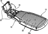
Fig. 1 is the exploded view that shows according to the lighting device of first embodiment of the invention;
Fig. 2 is the assembly drawing that shows this lighting device;
Fig. 3 is the viewgraph of cross-section that shows optical controlling function unit in this lighting device;
Fig. 4 is a view of describing the thickness in the thickness in power module zone in this lighting device and LED luminous component zone;
Fig. 5 is the view of the clipped of LED luminous component in the display illumination device;
Fig. 6 is the view of the release conditions of covering member in the diagram lighting device;
Fig. 7 is the view of the connection form of diagram lighting device;
Fig. 8 A is the view of radiating fin in the display illumination device;
Fig. 8 B is a view of describing drainage direction and heat dissipation direction in the lighting device;
Fig. 8 C is the side view of lighting device shown in Fig. 8 B;
Fig. 9 is a view of describing radiating fin height in the lighting device;
Figure 10 is the view of optical controlling function unit in the display illumination device; And
Figure 11 is the view of optical controlling function unit in the display illumination device.
The specific embodiment
Below with reference to the accompanying drawing that constitutes an embodiment of the invention part lighting device according to the embodiment of the invention is described.
(first embodiment)
Fig. 1 is the exploded view that shows according to the lighting device 1 of first embodiment of the invention.Fig. 2 is its assembled view.
This lighting device 1 comprises the main body 12 that links to each other with arm 11 as supporting member and supported by this arm 11, the upper cover part 13 that is used for main body covered 12 tops, LED luminous component 14 and as the power module 15 of power subsystem, LED luminous component and power module all are located at the downside of described upper cover part 13, the downside that luminous plaque 16 is located at described main body 12 is with the light of transmission from LED luminous component 14, and power module accomodating unit 17 is outstanding downwards to hold power module 15 in wherein from main body 12.
As what hereinafter will be described, the section thickness T1 at place, LED luminous component 14 places of lighting device 1 is arranged to the thickness T 2 little (referring to Fig. 4) according to the cross section at the place, power module 15 places of bright device 1.Having control is located on the outer surface of power module accomodating unit 17 from the optical controlling function unit 21 of the function of the light of luminous plaque 16.Power module 15 is arranged near arm 11.Electric wire connection space 18 is located in the main body 12 near arm 11, and in electric wire connection space 18, the electric wire of Yin Jining is connected to power module 15 from the outside.Electric wire connection space 18 is opened and closed by covering member 19.
A plurality of radiating fins 23 (referring to Fig. 6) are located at the top of upper cover part 13.Radiating fin 23 upper cover part 13 vertically on extend to arm 11.The groove 23a that limits between adjacent radiating fin 23 is downward-sloping towards the periphery of upper cover part 13.Further, main body 12 can be positioned to towards arm 11 downward-sloping.LED luminous component 14 is arranged away from arm 11.
Next, each element with illumination apparatus 1 is described.Electric wire connection space 18 and covering member 19 are located in the main body 12 side opposite with luminous plaque 16.The arm insertion portion 20 that is used to insert arm 11 is located at the downside of electric wire connection space 18.
Power module accomodating unit 17 and the power module 15 that is contained in wherein are located near the arm insertion portion 20.Therefore, power module 15 is arranged near arm 11.Replacedly, power module 15 also can be disposed in a side opposite with arm 11.As shown in Figure 3, optical controlling function unit 21 is used for controlling the light from luminous plaque 16.The example of optical controlling function comprises reflection of light, absorbs and cuts sth. askew.
In the present embodiment, optical controlling function unit 21 is located on the outer surface of end of close luminous plaque 16 of power module accomodating unit 17.Optical controlling function unit 21 is included in downward-sloping inclined surface 21a on the direction away from luminous plaque 16.Luminous energy from luminous plaque 16 comes controlled by shape or the coating on the inclined surface 21a of Change Example such as inclined surface 21a.
In the present embodiment, as shown in Figure 3, inclined surface 21a is constructed to not reflect the light from luminous plaque 16, like this, from the light of luminous plaque 16 not with light interference from inclined surface 21a reflection.In this respect, might come to control light and realize that required light distributes by the angle of inclination or the coating that change inclined surface 21a in the mode of needs.
In addition, as described above with reference to Figure 4, lighting device 1 is constructed such that the section thickness T1 of the lighting device 1 at LED luminous component 14 places places becomes littler than the section thickness T2 of the lighting device 1 at place, power module 15 places.This makes that remove the parts 27 by Fig. 5 dotted line that are arranged in below the luminous plaque 16 becomes possibility, and this has reduced the size and the weight of lighting device 1.
Forward Fig. 6 to, be used to lock and the bolt lock mechanism 22 that discharges covering member 19 is located at covering member 19 and main body 22 places.Electric wire connection space 18 can be opened by covering member 19 with these bolt lock mechanism 22 releases.
Radiating fin 23 is located on the whole top surface of upper cover part 13.The groove that limits between adjacent radiating fin 23 is formed towards the periphery of upper cover part 13 downward-sloping.In the present embodiment, radiating fin 23 is along the longitudinal extension of upper cover part 13 and be arranged to the relation that is parallel to each other.
When arm 11 is inserted in the arm insertion portion 20, as shown in Figure 7, lighting device 1 is with 24 one-tenth special angles with respect to the horizontal plane and be connected to arm 11 with being tilted, thereby the part of installing 1 close arm 11 can be positioned in downside, and the part of installing 1 carrying LED luminous component 14 is positioned at upside.
As a result, the groove 23a that is limited between the adjacent radiating fin 23 has a down dip towards arm 11 1 side direction from LED luminous component 14 1 sides.Therefore, shown in Fig. 8 A to 8C, fall the water of for example rainwater or the like on the upper cover part 13 and in Fig. 8 B, drained on the drainage direction shown in the solid arrow 25 along the groove 23a between the adjacent radiating fin 23.The heat that produces in the lighting device 1 is shed on the heat dissipation direction 26 shown in the single-point line arrow in Fig. 8 B by radiating fin 23.Therefore, can carry out draining and heat radiation in an efficient way.
With reference to Fig. 9, the height of radiating fin 23 is set to satisfy inequality H1<H2, and wherein H1 is illustrated in the height of the radiating fin 23 of arm 11 sides, and H2 is illustrated in the height of the radiating fin 23 of LED luminous component 14 sides.This makes might further increase radiating efficiency.Because LED luminous component 14 is set to away from arm 11, heat radiation further improves.
Employing is according to the lighting device in the first embodiment of the invention 1, and drainage and thermal diffusivity can both be enhanced, because the groove 23a between the adjacent radiating fin 23 is downward-sloping towards the periphery of upper cover part 13.
Because main body 12 be configured to towards arm 11 downward-sloping and radiating fin 23 towards arm 11 extend (that is, and upper cover part 13 vertically on), drainage and thermal diffusivity further improve.
Because LED luminous component 14 is arranged to away from arm 11, thermal diffusivity further improves.
(second embodiment)
Figure 10 has shown according to the optical controlling function unit 30 in the lighting device of second embodiment of the invention.In the following description, with first embodiment in same element will represent and no longer specifically describe with same Reference numeral.
Optical controlling function unit 30 comprises the reflecting surface 30a of cardinal principle perpendicular to luminous plaque 16.Coating with high reflectance is applied on this reflecting surface 30a.Described reflecting surface 30a is at the light of (that is, on the direction opposite with arm 11) reflection from luminous plaque 16 that forwards makes progress.This makes and guides light to become possibility forward.
(the 3rd embodiment)
Figure 11 has shown according to the optical controlling function unit 40 in the lighting device of third embodiment of the invention.Optical controlling function unit 40 comprises the non-reflecting surface 40a of cardinal principle perpendicular to luminous plaque 16.Coating with antiradar reflectivity is applied on this non-reflecting surface 40a.Therefore, this non-reflecting surface 40a is constrained to the light of reflection from luminous plaque 16 that can not make progress forwards.This makes that realizing back cutting the distribution of (back-cut) light becomes possibility.
Though the present invention illustrates and illustrate with regard to the foregoing description, it will be understood by those skilled in the art that and under the scope of the invention that does not break away from appended claim and limited, to carry out multiple change and modification.

Claims (4)

1. lighting device comprises:
Main body by support member support;
The upper cover part that is used for main body covered top; And
LED luminous component and power subsystem, described LED luminous component and power subsystem all are fixed to the downside of described upper cover part,
Wherein upper cover part comprises a plurality of radiating fin and a plurality of grooves that are limited between the adjacent radiating fin that are located at its top, and described groove is downward-sloping towards the periphery of upper cover part.
2. lighting device according to claim 1 is characterized in that, described main body is arranged to towards described supporting member that downward-sloping and described radiating fin extends towards described supporting member.
3. lighting device according to claim 1 is characterized in that, described LED luminous component is arranged to away from described supporting member.
4. lighting device according to claim 2 is characterized in that, described LED luminous component is arranged to away from described supporting member.
CN201110075551.0A 2010-03-29 2011-03-23 Illumination device Expired - Fee Related CN102207282B (en)

Applications Claiming Priority (2)

Application Number Priority Date Filing Date Title
JP075704/2010 2010-03-29
JP2010075704A JP5435799B2 (en) 2010-03-29 2010-03-29 Road lighting

Publications (2)

Publication Number Publication Date
CN102207282A true CN102207282A (en) 2011-10-05
CN102207282B CN102207282B (en) 2014-07-16

Family

ID=44237166

Family Applications (1)

Application Number Title Priority Date Filing Date
CN201110075551.0A Expired - Fee Related CN102207282B (en) 2010-03-29 2011-03-23 Illumination device

Country Status (4)

Country Link
US (1) US8517575B2 (en)
EP (1) EP2372227B1 (en)
JP (1) JP5435799B2 (en)
CN (1) CN102207282B (en)

Cited By (1)

* Cited by examiner, † Cited by third party
Publication number Priority date Publication date Assignee Title
CN105556198A (en) * 2013-08-26 2016-05-04 株式会社Kmw Led streetlamp

Families Citing this family (21)

* Cited by examiner, † Cited by third party
Publication number Priority date Publication date Assignee Title
GB2518528B (en) * 2012-03-15 2020-04-08 Hangzhou Hpwinner Opto Corp LED lighting device
US9121582B2 (en) * 2012-04-06 2015-09-01 Cree, Inc. LED light fixture with inter-fin air-flow interrupters
CA147071S (en) * 2012-08-22 2014-02-14 Led Roadway Lighting Ltd Light fixture having planar optics
US9435519B2 (en) * 2013-01-31 2016-09-06 Cree, Inc. Light-fixture support assembly
USD708775S1 (en) * 2013-08-27 2014-07-08 Zhuhai Leadsun Electronic Technology Co., Ltd. Integrated type of solar multimedia lamp
USD743606S1 (en) * 2013-11-04 2015-11-17 Enel Sole S.R.L. Public lighting fixture
USD743083S1 (en) * 2014-03-26 2015-11-10 Koninklijke Philips N.V. LED road luminaire
USD742574S1 (en) * 2014-03-26 2015-11-03 Koninklijke Philips N.V. LED road luminaire
USD744688S1 (en) * 2014-08-15 2015-12-01 General Electric Company Outdoor luminaire
KR101697471B1 (en) * 2014-12-31 2017-01-19 주식회사 아토텍 Security light device using LED
CN107532792A (en) 2015-04-30 2018-01-02 豪倍公司 Modular Area Lighting Fixtures
USD776859S1 (en) * 2015-04-30 2017-01-17 Hubbell Incorporated Area luminaire
KR101798492B1 (en) * 2016-02-15 2017-11-16 주식회사 루멘에어텍 Street light device using LED
USD831254S1 (en) * 2016-06-13 2018-10-16 Benjamin Pouladian Light fixture
USD831872S1 (en) * 2016-06-13 2018-10-23 Saman Sinai Light fixture
USD822261S1 (en) * 2016-06-24 2018-07-03 Cree, Inc. Light fixture
US10422172B2 (en) * 2016-06-30 2019-09-24 Appleton Grp Llc. Tool-less hinge mechanism
USD863643S1 (en) * 2016-09-29 2019-10-15 RAB Lighting Inc. Tapered LED light fixture
EP3312500B1 (en) * 2016-10-24 2020-06-17 Simon Lighting, S.A. Luminaire and cover for the luminaire
JP7133830B2 (en) * 2018-01-17 2022-09-09 アイリスオーヤマ株式会社 lighting equipment
USD928350S1 (en) * 2019-01-25 2021-08-17 Eaton Intelligent Power Limited Luminaire

Citations (8)

* Cited by examiner, † Cited by third party
Publication number Priority date Publication date Assignee Title
US20040196653A1 (en) * 2001-06-08 2004-10-07 Kevin Clark Exterior luminaire
US20060250803A1 (en) * 2005-05-04 2006-11-09 Chia-Yi Chen Street light with heat dispensing device
CN101101098A (en) * 2007-07-31 2008-01-09 宁波安迪光电科技有限公司 Large power LED road lamp
CN201100565Y (en) * 2008-01-10 2008-08-13 顾鹤彬 LED road lamp
US20090073681A1 (en) * 2007-05-31 2009-03-19 Kuei-Fang Chen Lighting Apparatus
US20090213588A1 (en) * 2008-02-14 2009-08-27 Robert Joel Manes Outdoor luminaire using light emitting diodes
KR20090093492A (en) * 2008-02-29 2009-09-02 주식회사 대진디엠피 Security light with led lamp
US20090237931A1 (en) * 2008-03-19 2009-09-24 Fu Zhun Precision Industry (Shen Zhen) Co., Ltd. Led lamp assembly

Family Cites Families (20)

* Cited by examiner, † Cited by third party
Publication number Priority date Publication date Assignee Title
JP2000222911A (en) * 1999-01-28 2000-08-11 Iwasaki Electric Co Ltd Road lighting fixtures
DE60140161D1 (en) * 2000-08-22 2009-11-26 Koninkl Philips Electronics Nv Luminaire based on LED light emission supported
JP3498290B1 (en) * 2002-12-19 2004-02-16 俊二 岸村 White LED lighting device
JP2004200102A (en) * 2002-12-20 2004-07-15 Kankyo Shomei:Kk Exterior illumination fixture by white light emitting diode
JP4730142B2 (en) * 2006-03-06 2011-07-20 岩崎電気株式会社 Lighting device
US8113687B2 (en) * 2006-06-29 2012-02-14 Cree, Inc. Modular LED lighting fixture
CN201078612Y (en) * 2007-07-20 2008-06-25 东莞勤上光电股份有限公司 LED street light
US7434959B1 (en) * 2007-08-14 2008-10-14 Augux Co., Ltd. LED lamp device
US7744247B2 (en) 2007-12-27 2010-06-29 Fu Zhun Precision Industry (Shen Zhen) Co., Ltd. LED lamp having double-side heat sink
JP4919982B2 (en) * 2008-02-08 2012-04-18 首都高速道路株式会社 LED lighting
JP3142540U (en) * 2008-03-07 2008-06-19 浩然科技股▲ふん▼有限公司 LED street light
US7665864B2 (en) * 2008-03-20 2010-02-23 Fu Zhun Precision Industry (Shen Zhen) Co., Ltd. LED lamp assembly
CN101545594B (en) * 2008-03-26 2010-09-29 富准精密工业(深圳)有限公司 LED Street Light
JP2009245846A (en) * 2008-03-31 2009-10-22 Suzhou Marsleds Optoelectronics Co Ltd Led street light
CN101566320B (en) * 2008-04-25 2011-12-28 富准精密工业(深圳)有限公司 Light-emitting diode lamp
JP2010040247A (en) * 2008-08-01 2010-02-18 Airec Engineering Corp Lighting fixture
JP3154164U (en) * 2009-02-27 2009-10-08 株式會社ケイエムダブリュ Lamp device
JP3150841U (en) * 2009-03-13 2009-06-04 熱速得控股股▲ふん▼有限公司 Combination structure of LED lighting device
US7976179B2 (en) * 2009-06-03 2011-07-12 System Photovoltaic Science Co., Ltd. Solar-lamp assembly
CN102080772A (en) * 2009-11-30 2011-06-01 富准精密工业(深圳)有限公司 Light-emitting diode lamp

Patent Citations (8)

* Cited by examiner, † Cited by third party
Publication number Priority date Publication date Assignee Title
US20040196653A1 (en) * 2001-06-08 2004-10-07 Kevin Clark Exterior luminaire
US20060250803A1 (en) * 2005-05-04 2006-11-09 Chia-Yi Chen Street light with heat dispensing device
US20090073681A1 (en) * 2007-05-31 2009-03-19 Kuei-Fang Chen Lighting Apparatus
CN101101098A (en) * 2007-07-31 2008-01-09 宁波安迪光电科技有限公司 Large power LED road lamp
CN201100565Y (en) * 2008-01-10 2008-08-13 顾鹤彬 LED road lamp
US20090213588A1 (en) * 2008-02-14 2009-08-27 Robert Joel Manes Outdoor luminaire using light emitting diodes
KR20090093492A (en) * 2008-02-29 2009-09-02 주식회사 대진디엠피 Security light with led lamp
US20090237931A1 (en) * 2008-03-19 2009-09-24 Fu Zhun Precision Industry (Shen Zhen) Co., Ltd. Led lamp assembly

Cited By (2)

* Cited by examiner, † Cited by third party
Publication number Priority date Publication date Assignee Title
CN105556198A (en) * 2013-08-26 2016-05-04 株式会社Kmw Led streetlamp
US10174893B2 (en) 2013-08-26 2019-01-08 Gigatera Inc. LED streetlamp

Also Published As

Publication number Publication date
US8517575B2 (en) 2013-08-27
EP2372227A3 (en) 2013-03-13
US20110235343A1 (en) 2011-09-29
JP5435799B2 (en) 2014-03-05
EP2372227B1 (en) 2015-03-11
JP2011210468A (en) 2011-10-20
EP2372227A2 (en) 2011-10-05
CN102207282B (en) 2014-07-16

Similar Documents

Publication Publication Date Title
CN102207282A (en) Illumination device
CN102563408B (en) Lighting device
CN101986004B (en) Lighting device
JP5634757B2 (en) Light source module
CN101725905B (en) Light-emitting diode lamp
JP2012104485A5 (en)
CA2768962A1 (en) Daylighting devices and methods with auxiliary lighting fixtures
JP3166727U (en) Solid state lighting fixture
JP2010056072A (en) Led lighting device and heat-dissipation watertight cover for the same
CN102980089A (en) Illuminating device and goods storage device with the same
RU2013152975A (en) LIGHTED LED DEVICE WITH TOP HEAT DISPERSION STRUCTURE
JP4739157B2 (en) Lighting lamp
JP5435800B2 (en) Road lighting
CN102168814B (en) Lighting device
KR101848801B1 (en) Lighting device
EP2481971A1 (en) Reflective light emitting diode lamp
JP6854863B2 (en) Light source unit
KR101047441B1 (en) Lighting device
KR101054839B1 (en) Lighting device
KR20110113698A (en) Lighting device
KR101652813B1 (en) Lighting device
KR101652816B1 (en) Lighting device
KR101652807B1 (en) Lighting device
KR101652775B1 (en) Lighting device
JP5932937B2 (en) Light source substrate support member and light source module

Legal Events

Date Code Title Description
C06 Publication
PB01 Publication
C10 Entry into substantive examination
SE01 Entry into force of request for substantive examination
ASS Succession or assignment of patent right

Owner name: MATSUSHITA ELECTRIC INDUSTRIAL CO, LTD.

Free format text: FORMER OWNER: MATSUSHITA ELECTRIC WORKS LTD.

Effective date: 20120229

C41 Transfer of patent application or patent right or utility model
TA01 Transfer of patent application right

Effective date of registration: 20120229

Address after: Osaka Japan

Applicant after: Matsushita Electric Industrial Co., Ltd.

Address before: Osaka Japan

Applicant before: Matsushita Electric Works, Ltd.

C14 Grant of patent or utility model
GR01 Patent grant
CF01 Termination of patent right due to non-payment of annual fee

Granted publication date: 20140716

Termination date: 20200323

CF01 Termination of patent right due to non-payment of annual fee