CN102186526B - Detachable tip microcatheter - Google Patents
Detachable tip microcatheter Download PDFInfo
- Publication number
- CN102186526B CN102186526B CN2009801415998A CN200980141599A CN102186526B CN 102186526 B CN102186526 B CN 102186526B CN 2009801415998 A CN2009801415998 A CN 2009801415998A CN 200980141599 A CN200980141599 A CN 200980141599A CN 102186526 B CN102186526 B CN 102186526B
- Authority
- CN
- China
- Prior art keywords
- microcatheter
- tip
- tubular body
- sleeve
- force
- Prior art date
- Legal status (The legal status is an assumption and is not a legal conclusion. Google has not performed a legal analysis and makes no representation as to the accuracy of the status listed.)
- Expired - Fee Related
Links
Images


Classifications
-
- A—HUMAN NECESSITIES
- A61—MEDICAL OR VETERINARY SCIENCE; HYGIENE
- A61M—DEVICES FOR INTRODUCING MEDIA INTO, OR ONTO, THE BODY; DEVICES FOR TRANSDUCING BODY MEDIA OR FOR TAKING MEDIA FROM THE BODY; DEVICES FOR PRODUCING OR ENDING SLEEP OR STUPOR
- A61M25/00—Catheters; Hollow probes
- A61M25/01—Introducing, guiding, advancing, emplacing or holding catheters
-
- A—HUMAN NECESSITIES
- A61—MEDICAL OR VETERINARY SCIENCE; HYGIENE
- A61B—DIAGNOSIS; SURGERY; IDENTIFICATION
- A61B17/00—Surgical instruments, devices or methods
- A61B17/12—Surgical instruments, devices or methods for ligaturing or otherwise compressing tubular parts of the body, e.g. blood vessels or umbilical cord
- A61B17/12022—Occluding by internal devices, e.g. balloons or releasable wires
- A61B17/12131—Occluding by internal devices, e.g. balloons or releasable wires characterised by the type of occluding device
- A61B17/12181—Occluding by internal devices, e.g. balloons or releasable wires characterised by the type of occluding device formed by fluidized, gelatinous or cellular remodelable materials, e.g. embolic liquids, foams or extracellular matrices
- A61B17/12186—Occluding by internal devices, e.g. balloons or releasable wires characterised by the type of occluding device formed by fluidized, gelatinous or cellular remodelable materials, e.g. embolic liquids, foams or extracellular matrices liquid materials adapted to be injected
-
- A—HUMAN NECESSITIES
- A61—MEDICAL OR VETERINARY SCIENCE; HYGIENE
- A61B—DIAGNOSIS; SURGERY; IDENTIFICATION
- A61B17/00—Surgical instruments, devices or methods
- A61B17/12—Surgical instruments, devices or methods for ligaturing or otherwise compressing tubular parts of the body, e.g. blood vessels or umbilical cord
- A61B17/12022—Occluding by internal devices, e.g. balloons or releasable wires
- A61B17/12099—Occluding by internal devices, e.g. balloons or releasable wires characterised by the location of the occluder
- A61B17/12109—Occluding by internal devices, e.g. balloons or releasable wires characterised by the location of the occluder in a blood vessel
- A61B17/12113—Occluding by internal devices, e.g. balloons or releasable wires characterised by the location of the occluder in a blood vessel within an aneurysm
-
- A—HUMAN NECESSITIES
- A61—MEDICAL OR VETERINARY SCIENCE; HYGIENE
- A61L—METHODS OR APPARATUS FOR STERILISING MATERIALS OR OBJECTS IN GENERAL; DISINFECTION, STERILISATION OR DEODORISATION OF AIR; CHEMICAL ASPECTS OF BANDAGES, DRESSINGS, ABSORBENT PADS OR SURGICAL ARTICLES; MATERIALS FOR BANDAGES, DRESSINGS, ABSORBENT PADS OR SURGICAL ARTICLES
- A61L29/00—Materials for catheters, medical tubing, cannulae, or endoscopes or for coating catheters
- A61L29/14—Materials characterised by their function or physical properties, e.g. lubricating compositions
- A61L29/16—Biologically active materials, e.g. therapeutic substances
-
- A—HUMAN NECESSITIES
- A61—MEDICAL OR VETERINARY SCIENCE; HYGIENE
- A61M—DEVICES FOR INTRODUCING MEDIA INTO, OR ONTO, THE BODY; DEVICES FOR TRANSDUCING BODY MEDIA OR FOR TAKING MEDIA FROM THE BODY; DEVICES FOR PRODUCING OR ENDING SLEEP OR STUPOR
- A61M25/00—Catheters; Hollow probes
- A61M25/0021—Catheters; Hollow probes characterised by the form of the tubing
-
- A—HUMAN NECESSITIES
- A61—MEDICAL OR VETERINARY SCIENCE; HYGIENE
- A61M—DEVICES FOR INTRODUCING MEDIA INTO, OR ONTO, THE BODY; DEVICES FOR TRANSDUCING BODY MEDIA OR FOR TAKING MEDIA FROM THE BODY; DEVICES FOR PRODUCING OR ENDING SLEEP OR STUPOR
- A61M25/00—Catheters; Hollow probes
- A61M25/0043—Catheters; Hollow probes characterised by structural features
- A61M25/005—Catheters; Hollow probes characterised by structural features with embedded materials for reinforcement, e.g. wires, coils, braids
-
- A—HUMAN NECESSITIES
- A61—MEDICAL OR VETERINARY SCIENCE; HYGIENE
- A61M—DEVICES FOR INTRODUCING MEDIA INTO, OR ONTO, THE BODY; DEVICES FOR TRANSDUCING BODY MEDIA OR FOR TAKING MEDIA FROM THE BODY; DEVICES FOR PRODUCING OR ENDING SLEEP OR STUPOR
- A61M25/00—Catheters; Hollow probes
- A61M25/0067—Catheters; Hollow probes characterised by the distal end, e.g. tips
- A61M25/0068—Static characteristics of the catheter tip, e.g. shape, atraumatic tip, curved tip or tip structure
- A61M25/0069—Tip not integral with tube
-
- A—HUMAN NECESSITIES
- A61—MEDICAL OR VETERINARY SCIENCE; HYGIENE
- A61M—DEVICES FOR INTRODUCING MEDIA INTO, OR ONTO, THE BODY; DEVICES FOR TRANSDUCING BODY MEDIA OR FOR TAKING MEDIA FROM THE BODY; DEVICES FOR PRODUCING OR ENDING SLEEP OR STUPOR
- A61M25/00—Catheters; Hollow probes
- A61M25/01—Introducing, guiding, advancing, emplacing or holding catheters
- A61M25/0105—Steering means as part of the catheter or advancing means; Markers for positioning
- A61M25/0108—Steering means as part of the catheter or advancing means; Markers for positioning using radio-opaque or ultrasound markers
-
- A—HUMAN NECESSITIES
- A61—MEDICAL OR VETERINARY SCIENCE; HYGIENE
- A61M—DEVICES FOR INTRODUCING MEDIA INTO, OR ONTO, THE BODY; DEVICES FOR TRANSDUCING BODY MEDIA OR FOR TAKING MEDIA FROM THE BODY; DEVICES FOR PRODUCING OR ENDING SLEEP OR STUPOR
- A61M25/00—Catheters; Hollow probes
- A61M25/01—Introducing, guiding, advancing, emplacing or holding catheters
- A61M25/09—Guide wires
-
- A—HUMAN NECESSITIES
- A61—MEDICAL OR VETERINARY SCIENCE; HYGIENE
- A61B—DIAGNOSIS; SURGERY; IDENTIFICATION
- A61B17/00—Surgical instruments, devices or methods
- A61B2017/00831—Material properties
- A61B2017/00955—Material properties thermoplastic
-
- A—HUMAN NECESSITIES
- A61—MEDICAL OR VETERINARY SCIENCE; HYGIENE
- A61B—DIAGNOSIS; SURGERY; IDENTIFICATION
- A61B17/00—Surgical instruments, devices or methods
- A61B17/12—Surgical instruments, devices or methods for ligaturing or otherwise compressing tubular parts of the body, e.g. blood vessels or umbilical cord
- A61B17/12022—Occluding by internal devices, e.g. balloons or releasable wires
- A61B2017/1205—Introduction devices
-
- A—HUMAN NECESSITIES
- A61—MEDICAL OR VETERINARY SCIENCE; HYGIENE
- A61M—DEVICES FOR INTRODUCING MEDIA INTO, OR ONTO, THE BODY; DEVICES FOR TRANSDUCING BODY MEDIA OR FOR TAKING MEDIA FROM THE BODY; DEVICES FOR PRODUCING OR ENDING SLEEP OR STUPOR
- A61M25/00—Catheters; Hollow probes
- A61M25/0021—Catheters; Hollow probes characterised by the form of the tubing
- A61M2025/0042—Microcatheters, cannula or the like having outside diameters around 1 mm or less
Landscapes
- Health & Medical Sciences (AREA)
- Life Sciences & Earth Sciences (AREA)
- Veterinary Medicine (AREA)
- Engineering & Computer Science (AREA)
- Biomedical Technology (AREA)
- Animal Behavior & Ethology (AREA)
- General Health & Medical Sciences (AREA)
- Public Health (AREA)
- Heart & Thoracic Surgery (AREA)
- Anesthesiology (AREA)
- Pulmonology (AREA)
- Hematology (AREA)
- Biophysics (AREA)
- Surgery (AREA)
- Molecular Biology (AREA)
- Reproductive Health (AREA)
- Nuclear Medicine, Radiotherapy & Molecular Imaging (AREA)
- Vascular Medicine (AREA)
- Medical Informatics (AREA)
- Neurosurgery (AREA)
- Chemical & Material Sciences (AREA)
- Medicinal Chemistry (AREA)
- Epidemiology (AREA)
- Surgical Instruments (AREA)
- Media Introduction/Drainage Providing Device (AREA)
- Materials For Medical Uses (AREA)
Abstract
Description
优先权要求priority claim
本申请要求2008年8月19日递交的美国临时专利申请No.61/090,185和2008年8月19日递交的美国临时专利申请No.61/090,188的基于35U.S.C.§119(e)的权益,通过引用将这两个美国临时专利申请中的每一个的全部内容结合于此。This application claims the benefit under 35 U.S.C. § 119(e) of U.S. Provisional Patent Application No. 61/090,185, filed August 19, 2008, and U.S. Provisional Patent Application No. 61/090,188, filed August 19, 2008 , the entire contents of each of these two US Provisional Patent Applications are hereby incorporated by reference.
技术领域technical field
本申请涉及可分离末端的导管,包括具有热塑性套管的可分离的、生物相容末端的微型导管。The present application relates to detachable-tipped catheters, including detachable, biocompatible-tipped microcatheters with thermoplastic sleeves.
背景技术Background technique
微型导管,包括神经微型导管,通常为通过诸如股动脉的血管插入身体中的微型管,并具有多种用途(参见,例如,美国专利No.6,306,124和6,454,738)。微型导管具有远端和近端,其中,典型地,在最远端处或靠近最远端处,采用标记带以允许临床医师观察体内使用期间定位的微型导管。标记带典型地包括金属或金属合金环,例如铂、镍钛合金和/或金环,从而可以通过荧光透视检查观察到。Microcatheters, including neural microcatheters, are typically tiny tubes that are inserted into the body through blood vessels such as the femoral artery and have a variety of uses (see, eg, US Patent Nos. 6,306,124 and 6,454,738). The microcatheter has a distal end and a proximal end, wherein, typically, at or near the most distal end, a marking band is employed to allow a clinician to observe the microcatheter as it is positioned during in vivo use. The marker band typically includes a ring of metal or metal alloy, such as platinum, nitinol, and/or gold, so that it can be seen under fluoroscopy.
微型导管典型地用来以相对非侵入式方式例如在处理动静脉畸形(AVM)、动脉瘤和类似病症中使神经血管系统发生栓塞。例如,参见Jones等人(美国专利No.5,843,050),其披露了用于处理小的弯曲脉管或神经血管系统的微型导管。Microcatheters are typically used to embolize the neurovasculature in a relatively non-invasive manner, eg, in the treatment of arteriovenous malformations (AVMs), aneurysms, and similar conditions. See, eg, Jones et al. (US Patent No. 5,843,050), which discloses microcatheters for treating small tortuous vessels or neurovasculature.
适于许多不同应用的多种微型导管在市场上可购得。神经与血管栓塞装置包括血管内合成物,其在体内固化以永久地堵塞至脑动脉瘤和脑动静脉畸形的血流。适当的血管内合成物包括(仅以举例的方式)在体内聚合以形成硬块的氰基丙烯酸酯以及溶解在诸如二甲亚砜(“DMSO”)的非水溶剂中的生物相容的、不溶于水的聚合物溶液,因而一旦引入脉管系统,DMSO消散,而所述聚合物沉淀在水基血液成分中。这种血管内合成物还包括用于帮助观察所形成的硬块的造影剂。A variety of microcatheters are commercially available for many different applications. Neuro- and vascular-embolic devices include intravascular compositions that solidify in the body to permanently occlude blood flow to cerebral aneurysms and cerebral arteriovenous malformations. Suitable intravascular compositions include (by way of example only) cyanoacrylates that polymerize in vivo to form hard masses and biocompatible, insoluble A solution of the polymer in water, so once introduced into the vasculature, the DMSO dissipates and the polymer precipitates in the water-based blood component. The intravascular composition also includes a contrast agent to aid in visualization of the formed lump.
与特别用在影响神经与血管栓塞中的微型导管相关联的一个问题是称为“逆流”的现象。典型地,在神经与血管栓塞期间,硬块由栓塞剂形成,例如栓塞液体,所述栓塞剂原位输送至栓塞位置。诸如氰基丙烯酸酯预聚物的预聚物或诸如
当逆流或血管痉挛发生时,考虑到脉管撕裂或破裂,临床医师通常不愿意使用过多的力去除神经微型导管。典型地,临床医师或者必须试图通过力撤回神经微型导管(这通常造成微型导管破裂),或者必须切断微型导管。在任一种情况中,神经微型导管的一部分都会残留在患者的脉管系统中。可选地,临床医师会试图通过未充满空腔来最小化逆流,未充满空腔由此带来比期望的治疗效果小的效果,并且也不能完全消除神经微型导管被捕获的风险。When reflux or vasospasm occurs, clinicians are often reluctant to use excessive force to remove the nerve microcatheter due to vessel tearing or rupture. Typically, the clinician must either attempt to withdraw the nerve microcatheter by force (which often causes the microcatheter to rupture), or the microcatheter must be severed. In either case, a portion of the neural microcatheter remains in the patient's vasculature. Alternatively, the clinician may try to minimize reflux by underfilling the cavity, which would result in less than the desired therapeutic effect and would not completely eliminate the risk of nerve microconduit entrapment.
发明内容Contents of the invention
在此描述的实施方式中的至少一个的一个方面包括这种实现,即有利地提供一种微型导管,所述微型导管可以在其由于任何原因被捕获在脉管系统中的情况中安全地从患者体内移除,同时最小化由这种复杂情况引起的潜在有害效应。进一步有利的是提供一种微型导管,所述微型导管可以维持高爆裂强度,以在栓塞剂注入期间抑制微型导管分离或爆裂,以及维持低的撤回力,用于在输送栓塞剂之前和/或之后在逆流情况中移除微型导管。An aspect of at least one of the embodiments described herein includes the realization that it is advantageous to provide a microcatheter that can be safely removed from the removal from the patient's body while minimizing potentially harmful effects arising from this complication. It would be further advantageous to provide a microcatheter that can maintain a high burst strength to inhibit detachment or bursting of the microcatheter during embolic agent injection, as well as maintain a low withdrawal force for use prior to and/or during embolic agent delivery. The microcatheter is then removed in case of reflux.
因此,根据至少一个实施方式,一种采用微型导管的方法可以包括使微型导管前进到患者体内的步骤,该微型导管包括:细长柔性管状本体,所述管状本体具有近端、远端和轴向地延伸通过所述管状本体的至少一个管腔;末端体,所述末端体具有近端、远端和轴向地延伸通过所述末端体的管腔;和热塑性装配的套管,所述套管覆盖管状本体的远端和末端体的近端。该方法还可以包括下述步骤:将末端体放置在脉管部位处;通过管状本体的管腔和末端体的管腔输送栓塞剂;以及通过向管状本体施加撤回力将末端体从管状本体上分离,末端体与栓塞剂保持在一起。Thus, according to at least one embodiment, a method of employing a microcatheter can include the step of advancing a microcatheter into a patient, the microcatheter comprising: an elongated flexible tubular body having a proximal end, a distal end, and a shaft At least one lumen extending through the tubular body; a tip body having a proximal end, a distal end, and a lumen extending axially through the tip body; and a thermoplastically assembled sleeve, the A sleeve covers the distal end of the tubular body and the proximal end of the tip body. The method may also include the steps of: placing the tip body at the vascular site; delivering an embolic agent through the lumen of the tubular body and the lumen of the tip body; and removing the tip body from the tubular body by applying a retraction force to the tubular body Separated, the end body remains with the embolic agent.
根据另一种实施方式,一种用于将栓塞剂输送至患者体内的脉管部位的微型导管可以包括:细长柔性管状本体,所述管状本体具有近端、远端和轴向地延伸通过所述管状本体的至少一个管腔;末端体,所述末端体具有近端、远端和轴向地延伸通过所述末端体的管腔;和热塑性装配的套管,所述套管覆盖管状本体和末端体二者的一部分;其中,套管与管状本体和末端体都摩擦接合,并且通过施加撤回力,末端可与管状本体和末端体中的一个分离。According to another embodiment, a microcatheter for delivering an embolic agent to a vascular site in a patient may include an elongated flexible tubular body having a proximal end, a distal end, and a At least one lumen of the tubular body; a tip body having a proximal end, a distal end, and a lumen extending axially through the tip body; and a thermoplastically assembled sleeve covering the tubular body. A portion of both the body and the tip body; wherein the sleeve is in frictional engagement with both the tubular body and the tip body, and the tip is detachable from one of the tubular body and the tip body by application of a retracting force.
附图说明Description of drawings
当阅读接下来的详细描述并参照这些实施方式的附图,这些实施方式的这些和其它特征和优点将变得更明显,在附图中:These and other features and advantages of these embodiments will become more apparent when reading the ensuing detailed description and when referring to the accompanying drawings of these embodiments, in which:
图1A为根据一种实施方式的微型导管的侧视图;Figure 1A is a side view of a microcatheter according to one embodiment;
图1B为图1A的微型导管的末端分离部的放大视图;FIG. 1B is an enlarged view of a distal separation portion of the microcatheter of FIG. 1A;
图2A为采用图1A的微型导管治疗动脉瘤的定位方法的示意图;2A is a schematic diagram of a positioning method for aneurysm treatment using the microcatheter of FIG. 1A;
图2B为图1A的微型导管的一部分的放大视图,示出了从微型导管管状本体上可分离地释放的微型导管末端体和热塑性套管;2B is an enlarged view of a portion of the microcatheter of FIG. 1A showing a microcatheter tip body and a thermoplastic sleeve detachably releasable from the microcatheter tubular body;
图2C为图1A的微型导管的一部分的放大视图,示出了从微型导管管状本体和热塑性套管上可分离地释放的微型导管末端体;2C is an enlarged view of a portion of the microcatheter of FIG. 1A showing a microcatheter tip body detachably releasable from the microcatheter tubular body and thermoplastic sleeve;
图2D为动静脉畸形的示意图;Figure 2D is a schematic diagram of an arteriovenous malformation;
图2E为采用图1A的微型导管治疗动静脉畸形的定位方法的示意图;2E is a schematic diagram of a positioning method for treating arteriovenous malformations using the microcatheter of FIG. 1A;
图3为图1A的微型导管管状本体、末端体和热塑性套管的示意图;Figure 3 is a schematic diagram of the microcatheter tubular body, tip body and thermoplastic sleeve of Figure 1A;
图4为图1A的可分离地接合至微型导管的管状本体的热塑性套管的示意图;4 is a schematic illustration of the thermoplastic sleeve of FIG. 1A detachably joined to the tubular body of the microcatheter;
图5为图1A的可分离地接合至微型导管的管状本体和末端体的热塑性套管的示意图,图5还示出了末端体中的侧孔;5 is a schematic illustration of the thermoplastic sleeve of FIG. 1A detachably coupled to the tubular body and tip body of the microcatheter, FIG. 5 also showing a side hole in the tip body;
图6为根据另一种实施方式的微型导管的示意性侧视图;Figure 6 is a schematic side view of a microcatheter according to another embodiment;
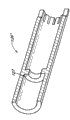
图7A为图6的微型导管的末端分离区的放大横截面图;FIG. 7A is an enlarged cross-sectional view of the distal separation region of the microcatheter of FIG. 6;
图7B为根据另一种实施方式的套管的立体横截面图;7B is a perspective cross-sectional view of a sleeve according to another embodiment;
图7C为根据另一种实施方式的套管的立体横截面图;7C is a perspective cross-sectional view of a cannula according to another embodiment;
图8为图6的微型导管的末端体的放大横截面图;Figure 8 is an enlarged cross-sectional view of the tip body of the microcatheter of Figure 6;
图9为图示图6的微型导管的爆裂强度和拆分力之间的关系的图表;9 is a graph illustrating the relationship between burst strength and disassembly force of the microcatheter of FIG. 6;
图10为根据另一种实施方式的包括薄壁分离部的微型导管的一部分的横截面图;10 is a cross-sectional view of a portion of a microcatheter including a thin-walled separation according to another embodiment;
图11为根据另一种实施方式的包括分离环的微型导管的一部分的横截面图;11 is a cross-sectional view of a portion of a microcatheter including a split ring according to another embodiment;
图12为根据另一种实施方式的具有分开制造的可分离末端的微型导管的一部分的横截面图;12 is a cross-sectional view of a portion of a microcatheter having a separately fabricated detachable tip according to another embodiment;
图13为根据另一种实施方式的微型导管的横截面图,示出了具有侧孔的末端;13 is a cross-sectional view of a microcatheter showing a tip with a side hole, according to another embodiment;
图14为根据另一种实施方式的微型导管的一部分的立体图,示出了包括夹紧结构的导管末端;和14 is a perspective view of a portion of a microcatheter showing a catheter tip including a gripping structure, according to another embodiment; and
图15为根据另一种实施方式的具有可分离末端、侧孔和标记带的微型导管的示意性侧视图。15 is a schematic side view of a microcatheter with a detachable tip, a side hole, and a marker band, according to another embodiment.
具体实施方式Detailed ways
除非另有限定,在此使用的所有技术和科学术语具有由本领域技术人员通常所理解的相同的含义。虽然在此描述的实施方式的实践或测试中可以使用类似于或等同于在此描述的方法和材料的任何方法和材料,但现在说明优选的方法、装置和材料。在此引用的所有公开文献和专利申请的全部内容在此并入本文供参考。Unless defined otherwise, all technical and scientific terms used herein have the same meaning as commonly understood by one of ordinary skill in the art. Although any methods and materials similar or equivalent to those described herein can be used in the practice or testing of the embodiments described herein, the preferred methods, devices, and materials are now described. The entire contents of all publications and patent applications cited herein are hereby incorporated by reference.
必须注意到,如在此和在随附权利要求中使用的那样,单数形式“一个”和“所述”包括复数引用,除非上下文清楚地另外指明了。It must be noted that, as used herein and in the appended claims, the singular forms "a" and "the" include plural referents unless the context clearly dictates otherwise.
具有热塑性套管的可分离末端微型导管Detachable-tipped microcatheter with thermoplastic sleeve
参照图1,微型导管10(例如,神经微型导管)可以用于将栓塞剂输送至患者的脉管部位。典型地,这些脉管部位位于神经脉管系统中且包括AVM和动脉瘤。然而,这种技术可以用在身体中的任何脉管中,并且可以用于栓塞任何体腔。微型导管10可以包括远端12、近端14以及在所述远端与所述近端之间延伸的细长柔性管状本体16。Referring to FIG. 1 , a microcatheter 10 (eg, a neural microcatheter) may be used to deliver an embolic agent to a vascular site in a patient. Typically, these vascular sites are located in the neurovasculature and include AVMs and aneurysms. However, this technique can be used in any vessel in the body and can be used to embolize any body cavity.
微型导管的远端12可以由生物相容的末端体30构成,末端体30通过套管26,例如热塑性套管(例如参见图1B),与管状本体16可分离地接合并同轴。“可分离地接合”的含义是,末端体30与管状本体16接合或连接至管状本体16;然而,这两者可以在施加可以预定的撤回力时脱离或分开。“撤回力”所表达的意思通常是指在近侧方向上(例如,在将从患者撤回微型导管的方向上)沿着微型导管10的纵向轴线(例如,平行于中心腔22)施加的拉力。用来将管状本体16从末端体30上分离的撤回力例如可以不大于约160克力,更优选地,可以在约10克力至约160克力的范围内。在特定的实施方式中,撤回力为约20克力至约40克力。在其它实施方式中,撤回力为约30克力至约50克力。也可以采用除上述范围之外的其它范围。管状本体16和末端体30可以具有相同或不同的外径和内径。微型导管10的近端14可以设置有歧管18。歧管18可以设置有至少一个进入口20,所述进入口通过细长中心腔22与远端进入口24流体连通。中心腔22允许微型导管10沿着导丝(未示出)前进。在去除导丝之后,中心腔22可以用来将栓塞剂输送至期望的脉管部位。The
为了进一步帮助将栓塞剂输送至期望的脉管部位,末端体30可以任选地包含多个侧向孔洞或孔38。孔洞38的形状可以从圆形、椭圆形或其它形状中选择。To further aid in delivering the embolic agent to the desired vascular site,
在图1B中还示出的是中心腔22。虽然未具体地图示,但微型导管可以包含多个管腔。例如,一个管腔可以由导丝专用,而其它的管腔可以专用于栓塞剂的输送。微型导管10可以包含位于管状本体16的远端34上的标记32,例如不透射线的标记。标记32可以为由诸如铂、铂/铱、金、镍钛合金和类似材料的金属或金属合金制成的环或带。Also shown in FIG. 1B is the central lumen 22 . Although not specifically shown, the microcatheter may contain multiple lumens. For example, one lumen may be dedicated to the guidewire while the other lumen may be dedicated to the delivery of embolic agents. The
图2A示出了微型导管10在人体内的使用。具体地,微型导管10插入到患者中便利的位置,例如腹股沟。可以使用多种定位系统,例如导向微型导管,导丝还可以用来帮助定位。微型导管10或在此描述的其它微型导管可以移动通过脉管,直到末端体30到达治疗位置40,例如AVM或动脉瘤。微型导管10的位置可以通过观察不透射线的标记32进行监控。一旦微型导管10在脉管系统中处于其合适的位置,则可以将栓塞剂42输送至治疗位置40。栓塞剂42可以为液态栓塞剂,并且可以包括多种物质。适合的栓塞剂42包括包含生物相容的聚合物和原位聚合的预聚物的栓塞剂。液态栓塞剂还可以包括生物相容的溶剂和造影剂。在一种实施方式中,造影剂是不溶于水的。一种这样的例子是
参照图2A,在输送栓塞剂42之后,末端体30可能会被捕获在栓塞剂42内。在特定的实施方式中,套管26也可能会由栓塞剂42捕获或部分地捕获。为了从患者身上移除微型导管10,主治临床医师可以向管状本体16施加撤回力。当施加撤回力时,热塑性套管26可以1)保持连接至末端体30(图2B);2)保持连接至管状本体16(图2C);或者3)破裂成两个部件,由此保持部分地连接至管状本体16和末端体30(未示出)。Referring to FIG. 2A , after delivery of the
类似地,微型导管10或在此描述的其它微型导管可以用来治疗动静脉畸形(AVM)。图2D图示了AVM的例子,图2E图示了如何可以将微型导管10移动至AVM位置,以将栓塞剂42输送至该位置。类似于图2A-C,可以通过使用套管26和撤回力卸下末端30。Similarly, microcatheter 10 or other microcatheters described herein may be used to treat arteriovenous malformations (AVMs). Figure 2D illustrates an example of an AVM, and Figure 2E illustrates how the
套管26在施加所述力之后的位置会受到套管26如何接合至末端体30和管状本体16的结构的影响(参见图3)。可以以多种方式完成末端体30到套管26的接合和管状本体16到套管26的接合。例如,套管26可以与管状本体16的远端34重合(参见图4),和/或可以与末端体30的近端36重合(参见图5)。重合的量可以为确定用于分离末端体30的撤回力的因素。在一些实施方式中,套管26到末端体30或管状本体16的一种或两种连接可以为对接(端对端)。在一些实施方式中,远端34和近端36可以形成对接。The position of the
在此描述的微型导管的一个优点是在维持高爆裂强度的同时具有低且恒定的拆分力的能力。除了使用套管26将末端体30可分离地接合至管状本体16,这种优点还可以通过为管状本体16和套管26选择的材料、套管26与管状本体16和末端体30的重合长度、和/或将套管26固定至管状本体16和末端体30的构造实现。One advantage of the microcatheters described here is the ability to have low and constant unraveling forces while maintaining high burst strength. In addition to using the
管状本体16可以由本领域熟知的多种材料并以本领域熟知的用于优化爆裂强度的方式构造。在一种实施方式中,管状本体16可以由与二甲亚砜相容的材料构造而成。管状本体16还可以包括具有变化的柔性的区域,这种变化的柔性还可以由所采用的构造方法和材料来控制。理想的是在管状本体34的远端具有更加柔韧的区域。所述区域的构造的描述可以在美国专利5,843,050中找到,通过引用将该专利结合于此,并且该专利构成本说明书的一部分。可以通过层叠多种聚合物,例如聚酰亚胺、聚四氟乙烯、聚醚嵌段酰胺、聚酰胺和类似聚合物,构造管状本体16。管状本体16还可以可选地包括间距变化的编织物以增强爆裂强度。这种编织物的描述例如可以在美国专利公开文献2004-0153049中找到,通过引用将该专利公开文献结合于此,并且该专利构成本说明书的一部分。
末端体30可以由生物相容性材料制成。“生物相容”指的是,以所采用的数量计,当在患者内部使用时,所述材料基本上是无毒的且基本上不产生免疫反应。生物相容性材料可以包括缩管聚合物(shrink-tubing polymer),例如,聚醚嵌段酰胺,包括带有商标
在特定的实施方式中,末端体30还可以是“可生物降解的”。已知许多可生物降解/可生物侵蚀以不可生物降解的材料可用于构造微型导管末端。末端体30可以由原位可生物降解或可生物吸收的材料形成。可以使用可生物降解或可生物吸收材料或它们的一些组合,从而在预定的条件下允许生物降解/生物吸收。In certain embodiments, the
多种生物相容-可生物降解的材料在市场上可购得。用于选择用作生物材料的聚合物的一般标准是使机械性能和降解时间与应用需求相匹配。在美国专利No.4,938,763中提出了可以使用的聚合物质。例如,下述聚合物是生物相容的以及可生物降解的:A variety of biocompatible-biodegradable materials are commercially available. A general criterion for selecting a polymer for use as a biomaterial is to match the mechanical properties and degradation time to the application requirements. Polymeric materials that can be used are set forth in US Patent No. 4,938,763. For example, the following polymers are biocompatible and biodegradable:
DLPLA-聚(dl-丙交酯)DLPLA-poly(dl-lactide)
LPLA-聚(l-丙交酯)LPLA-poly(l-lactide)
PGA-聚乙交酯PGA-Polyglycolide
PDO-聚(二氧环己酮)PDO-Poly(dioxanone)
PGA-TMC-聚(乙交酯-共-三亚甲基碳酸酯)PGA-TMC-poly(glycolide-co-trimethylene carbonate)
PGA-LPLA-聚(l-丙交酯-共-乙交酯)PGA-LPLA-poly(l-lactide-co-glycolide)
PGA-DLPLA-聚(dl-丙交酯-共-乙交酯)PGA-DLPLA-poly(dl-lactide-co-glycolide)
LPLA-DLPLA-聚(l-丙交酯-共-dl-丙交酯)LPLA-DLPLA-poly(l-lactide-co-dl-lactide)
PDO-PGA-TMC-聚(乙交酯-共-三亚甲基碳酸酯-共-二氧环己酮)PDO-PGA-TMC-poly(glycolide-co-trimethylene carbonate-co-dioxanone)
一种这类可以适合的吸收材料为多羟基链烷酸酯类生物聚合物(“PHA”)。例如,一种这种PHA是重组生产的,且商标为TephaFLEX聚合物,目前从美国马萨诸塞州Cambridge市的Tepha公司可买到。One such absorbent material that may be suitable is a polyhydroxyalkanoate biopolymer ("PHA"). For example, one such PHA is produced recombinantly and is currently commercially available from Tepha Corporation of Cambridge, Massachusetts, USA under the trademark TephaFLEX polymer.
套管26可以由热塑性材料或可热缩的材料形成。理想地,所选择的热塑性塑料对管状本体16材料来说是优选的,并且可以被填充或未被填充。套管26可以包括多于一种的热塑性材料。实例包括:热塑性聚烯烃弹性体(TPE);丙烯酸树脂;赛璐珞;醋酸纤维素;乙烯-醋酸乙烯酯(EVA);乙烯乙烯醇(EVAL);氟塑料(PTFE,FEP,PFA,CTFE,ECTFE,ETFE);离聚物;丙烯酸树脂/PVC合金化聚合物;液晶聚合物(LCP);聚缩醛(POM或乙缩醛);聚丙烯腈(PAN或丙烯腈);聚酰胺(PA或尼龙);聚芳醚酮(PAEK或酮);聚丁二烯(PBD);聚丁烯(PB);聚已酸内酯(PCL);聚三氟氯乙烯(PCTFE);聚羟基链烷酸酯(PHA);聚酮(PK);聚酯;低密度聚乙烯(LDPE);线性低密度聚乙烯(LLDPE);聚乙烯(PE);聚醚酰亚胺(PEI);聚醚砜(PES);聚砜;聚乙烯氯化物(PEC);聚乳酸(PLA);聚甲基戊烯(PMP);聚苯醚(PPO);聚苯硫醚(PPS);聚邻苯二甲酰胺(PPA);聚丙烯(PP);聚苯乙烯(PS);聚氯乙烯(PVC);聚偏二氯乙烯(PVDC);及其组合。
套管26可以用诸如硫酸钡的不透射线的材料填充或不用该材料填充。
在一种实施方式中,热塑性塑料为热塑性弹性体。在一种实施方式中,热塑性塑料为可热缩聚烯烃,例如聚乙烯,而在另一种实施方式中,热塑性塑料为低密度聚乙烯和聚烯烃弹性体(DuPont
如上所述,将末端体30与管状本体16分离的能力会受到微型导管10的构造的影响,且具体地,受到将套管26可分离地接合至末端体30和管状本体16的构造的影响。微型导管10的总长度可以大致在从约150cm至约175cm的范围内,虽然其它范围也是可行的。管状本体16可以被选择为具有在从0.5mm至约1.5mm的范围内的外径,虽然其它直径也是可行的。在一些实施方式中,中心腔22的直径可以为约0.002英寸至约0.005英寸,如果使用导丝,则所述直径大于导丝的外径。在近端和远端可以恰当地修改这种直径。根据本文的公开内容,除在此描述的之外的其它尺寸也容易由本领域技术人员采用,以适合微型导管10的特定预期用途。As noted above, the ability to separate
可以如上所述设置管状本体16和末端体30。随后可以设置套管26,并通过在套管26与管状本体16和末端体30的接合处施加受控温度热源指定的时间,将套管26可分离地接合至管状本体16和末端体30。施加热源的时间以及温度可以影响形成在套管26和其它部件之间的粘结。当施加热源时,套管26可以通过机械结合(较小的微型导管和末端体周围的热收缩力)或熔融结合(其中套管、管状本体和/或末端体的材料熔化在一起)连接至管状本体16和末端体26。所述结合可以为较弱的抗拉强度结合,以在施加约10克力至约160克力,优选约20克力至50克力的撤回力时允许末端体30从管状本体16上分离。
在可选的构造方法中,套管26可以通过使用粘合剂和溶剂连接至末端体30和/或管状本体16。In an alternative method of construction,
如上所述,套管26与管状本体16和/或末端体30的重合量可以存在变化。所述重合量可以为将末端体30从管状本体16分离所需要的撤回力中的一个因素。套管26在管状本体16和/或末端体30上的重合越大,将这两个元件分离所需要的撤回力越大。在一些实施方式中,这种重合可以为从约0.5mm至约5mm。在一些实施方式中,所述重合可以为2mm至约4mm。其它重合范围也是可行的。As noted above, there may be variations in the amount of overlap of the
可以提供包括微型导管10或在此描述的其它微型导管和如上所述的液态栓塞剂的成套器具。A kit may be provided that includes
参照图6-8,微型导管110可以类似于上述的微型导管10。因此,微型导管110的类似部件由与微型导管10中的对应部件相同的附图标记表示,但附图标记增加100。6-8,
参照图7A,末端分离区可以包括管状本体116、热塑性装配的套管126和末端体130。类似于上述套管26,热塑性套管126可以套在管状本体116的远端134和末端体130的近端136上。在一些实施方式中,套管126或在此描述的任何套管在分离之前可以与管状本体116和末端体130摩擦接合,并且与管状本体116可以形成比与末端体116更紧的摩擦接合。一旦施加撤回力,则套管126可以因此趋向于留在管状本体116上,因此留下末端体130。Referring to FIG. 7A , the tip separation region may include a tubular body 116 , a thermoplastic fitted
继续参照图7A,管状本体116可以包括标记132。标记132可以被定位为使得所述标记位于套管126的下面,从而在分离末端体130之前确定套管126和末端体130的位置。With continued reference to FIG. 7A , tubular body 116 may include indicia 132 . Marker 132 may be positioned such that it is located underneath
图7B图示了套管126′的可选实施方式。除了套管126′可以包括内部隔离元件127之外,套管126′可以与上述套管126相似。内部隔离元件127可以设计为分别隔开管状本体116和末端体130的远端134和近端136,同时仍允许栓塞剂流过微型导管。上述隔离可以阻止远端134和近端136在热塑性装配的套管126′的加热之后相互接触和/或相互粘结或粘附。如果远端134和近端136相互粘结,则将它们分开所需要的拆分力可以增加。因此,隔离元件127可以有助于降低拆分力。隔离元件127可以与套管126′一体地形成,或者可以被单独地连接或插接。隔离元件127可以包括多种材料,包括但不限于金属或塑料,在一些实施方式中可以为垫圈形状。Figure 7B illustrates an alternative embodiment of a sleeve 126'. The sleeve 126' may be similar to the
图7C图示了套管126″的另一种可选实施方式。除了套管126″可以包括两个分开的隔离部件128a和128b之外,套管126″可以与上述套管126′和126″相似。部件128a和128b可以彼此成镜像,并且可以被连接(例如,粘附在一起或保持在一起)以形成套管126″。如同套管126′一样,套管126″可以包括隔离元件127,所述隔离元件可以用来隔开管状本体116和末端体130的远端134和近端136。FIG. 7C illustrates another alternative embodiment of the
参照图8,末端体130还可以包括标记133。标记133可以为沿着末端体130的一部分定位的不透射线的标记,并且可以用来在末端体130从管状本体116上分离之前和/或之后识别出末端体130的位置。Referring to FIG. 8 , the
参照图9,提供了图示图6-8的微型导管的静态爆裂强度和拆分力之间的关系的图表。如上所述,静态爆裂强度通常描述可以引起微型导管径向爆裂的内部压力(例如,由导管内的栓塞液体施加)。静态爆裂强度是微型导管的管壁爆裂处的压力。通常希望具有高的静态爆裂强度,以限制微型导管在使用期间爆裂的可能性。如果静压力升高的足够高,则这种内部压力可以引起微型导管爆裂或破裂。例如,通过夹紧或以其它方式固定微型导管的两端,将液体注入微型导管中,并允许微型导管内部的静压力径向压在管壁上,可以测试静态爆裂强度。还可以在各种阶段测试静态爆裂强度,例如,在第一次使用装置之前,和/或在装置使用给定时间周期之后(例如,在模拟1小时程序期间推动栓塞剂通过微型导管110之后)。通常,在第一使用之前,对于给定的拆分力可获得较高的爆裂强度。图9呈现在模拟使用微型导管110约1小时之后进行的静态爆裂测试。Referring to FIG. 9, a graph illustrating the relationship between static burst strength and disassembly force of the microcatheters of FIGS. 6-8 is provided. As noted above, static burst strength generally describes the internal pressure (eg, exerted by embolic fluid within the catheter) that can cause the microcatheter to burst radially. Static burst strength is the pressure at which the wall of the microcatheter bursts. A high static burst strength is generally desired to limit the likelihood of the microcatheter bursting during use. This internal pressure can cause the microcatheter to burst or rupture if the static pressure rises high enough. For example, static burst strength can be tested by clamping or otherwise securing the ends of the microcatheter, injecting a liquid into the microcatheter, and allowing the static pressure inside the microcatheter to radially press against the tube wall. Static burst strength can also be tested at various stages, e.g., before the device is used for the first time, and/or after the device has been used for a given period of time (e.g., after pushing embolic agent through the
如上所述,拆分力通常描述用于将末端体130从管状本体116分离需要轴向施加的拉力。拆分力可以由使用者施加,例如通过向近侧拉管状本体116的近端。通常理想的是具有低的拆分力,以限制分离末端体130所需要的力的大小。As noted above, the detachment force generally describes the axially applied pulling force required to separate the
同时处理爆裂和分离时的一个潜在问题是在管状本体116和末端体130之间的相交处出现爆裂的可能性。因此,诸如上述套管中的一种的机构可以用来阻止微型导管110爆裂,同时使末端体130的分离更容易。例如,套管26、126、126′或126″在维持高的爆裂强度的同时可以允许期望的拆分力。One potential problem when dealing with bursting and separation simultaneously is the possibility of bursting at the intersection between tubular body 116 and
如图9中的图表所示,在一种实施方式中,在使用套管126′时,用于维持在约50psi和400psi之间的静态爆裂强度的拆分力可以在约20-40克力的范围内。因此,如果套管126′被热塑性地环绕管状本体116装配到使分离所需的撤回力增加的程度(即,更紧的装配),则微型导管径向爆裂所需要的静压力的大小也将增加。在特定的实施方式中,微型导管10或110可以被设计为具有足够高的爆裂强度,例如在约150psi至450psi的范围内,更优选地至少为250psi,相关的所需拆分力例如在约24克力和54克力之间,并且在特定的实施方式中,不大于约40克力、35克力、30克力或25克力。在特定的实施方式中,在小于30克力的拆分力下,微型导管10或110可以呈现在约150psi至225psi之间的爆裂强度。在某些实施方式中,在约32-33克力之间的拆分力下,微型导管10或110可以呈现约275psi的爆裂强度。As shown in the graph in FIG. 9 , in one embodiment, the split force for maintaining a static burst strength between about 50 psi and 400 psi may be between about 20-40 grams force when using the
上述的微型导管10和110包括热塑性装配的套管26、126、126′和126″,所述套管用于可分离地接合微型导管的管状本体和末端体。热塑性装配的套管相对于用于将末端体可分离地保持到微型导管的管状本体的其它类型的结构或系统可以提供优点。例如,可以使用金属套管(例如,金属环),从而需要粘合剂以将所述环粘结至管状本体的远端和末端体。然而,与这种金属环一起使用的粘合剂可能会不希望地退化,使得金属环从微型导管上分离并变为患者身体中的栓塞物。此外,以这种方式使用粘合剂要求粘合剂在分离之前分解。如果粘合剂由栓塞剂本身分解,则分离过程会变得依赖于时间且花费比期望的时间长的时间,或者在一些情况中,在分离所需要的时间方面会是不可预知的。此外,用于分离末端体所需要的撤回力可以根据所使用的粘合剂的量、所使用的粘合剂的稠度、粘合剂的涂敷等改变。相反,上述微型导管具有利用单次撤回力快速、有效且稳定地将末端体从微型导管的管状本体上分离的优点。The
此外,在一些实施方式中,上述的套管26、126、126′和126″可以具有在抑制微型导管10或110爆裂方面提供进一步的优点的长度(例如,轴向地沿着内管腔)与外径之比。例如,在特定的实施方式中,套管126′在远端可以具有约8∶1的长度与外径之比,在近端具有9∶1的长度与外径之比。其它比率也是可行的。在特定的实施方式中,长度与外径之比至少为6∶1或7∶1。例如大至8∶1或9∶1的比率可以为微型导管提供增加的稳定性,并且通过提供更大的沿着管状本体116和末端体130的覆盖或重合而阻止爆裂。Additionally, in some embodiments, the
此外,在套管126’的近端具有比套管126’的远端上的长度与外径之比大的长度与外径之比可以帮助套管126’围绕管状本体116的装配比围绕末端体130的装配紧。这种装配差异可以使末端体130的分离更容易,同时在分离之后允许套管126’保持连接至管状本体116。In addition, having a length to outer diameter ratio at the proximal end of the sleeve 126' that is greater than the length to outer diameter ratio on the distal end of the sleeve 126' can help the fit of the sleeve 126' around the tubular body 116 more than around the distal end. The assembly of
参照图10-15,其它类型的可分离末端导管可以用来输送栓塞剂。至少在一些实施方式中,在图10-15中图示的并在此描述的导管的部件可以与上述导管10和110一起使用。Referring to Figures 10-15, other types of detachable tip catheters can be used to deliver embolic agents. In at least some embodiments, the components of the catheters illustrated in FIGS. 10-15 and described herein may be used with
如上所述,导管通常根据已知的导管设计原理来构造,并典型地由近端设置的刚性部分、中间半柔性部分和远端柔性部构成,远端柔性部设计为有助于每次特定的医疗应用期间越过预期遇到的小的弯曲脉管。导管的远端可以包含一个或多个不透射线的标记,以在医疗过程期间帮助临床医师观察导管位置。典型地,不透射线的标记定位在离导管的远端固定距离处。例如,一个不透射线的标记可以可选地靠近相邻于末端分离区放置,以帮助临床医师观察导管以及医疗过程的解剖后遗症(例如,栓塞)和末端分离。As noted above, catheters are generally constructed according to known catheter design principles and typically consist of a proximally disposed rigid portion, a central semi-flexible portion, and a distal flexible portion designed to facilitate each specific across the small tortuous vessels expected to be encountered during medical applications. The distal end of the catheter may contain one or more radiopaque markers to aid the clinician in viewing the catheter location during the medical procedure. Typically, radiopaque markers are positioned a fixed distance from the distal end of the catheter. For example, a radiopaque marker may optionally be placed adjacent to the tip detachment region to aid the clinician in viewing the catheter as well as anatomical sequelae of the medical procedure (eg, embolism) and tip detachment.
一些导管包括具有可分离末端的单体式导管。在此使用的术语“单体式”通常是指制造为单个元件的导管或部件的宽泛术语。将会认识到,“单体式导管”不是暗示整个导管装置由单个元件构成。而“单体式导管”是指导管的远端的包括预定分离区和可分离末端区的一部分的单体结构。Some catheters include a one-piece catheter with a detachable tip. As used herein, the term "unibody" generally refers to a broad term for a catheter or component manufactured as a single element. It will be appreciated that "one-piece catheter" does not imply that the entire catheter device is composed of a single element. By "unibody catheter" is meant a unitary structure of the distal end of the catheter comprising a portion of a predetermined detachment region and a detachable tip region.
在本质上,所述预定末端分离区可以为导管本体的脆弱部分或刚性部分。换句话说,所述预定末端分离区在施加力时的弹性比管状本体的弹性弱。除了预定分离点的脆弱/刚性构造控制断裂的位置之外,这种单体结构可以类似于传统的导管末端结构。这种设计对现有的单体式导管末端结构进行了改进,在现有的单体式导管末端结构中,末端基本是均匀的,并且在施加过大的力时,破裂沿着导管末端体随机出现。在实践中,导管在插入患者身体中可能变形,特别是在微脉管系统环境中。导管在预定末端分离区处可以是相对不易弯曲的或柔性的。因此,由于分离区具有比相邻的管道低的抗拉强度,导管末端可以在该预定区处选择性地分离。In essence, the predetermined tip separation zone may be a fragile part or a rigid part of the catheter body. In other words, the predetermined end separation zone is less elastic when a force is applied than the tubular body. Such a monolithic structure may be similar to conventional catheter tip structures, except that the weak/rigid configuration of the predetermined separation point controls the location of the fracture. This design improves upon existing one-piece catheter tip constructions where the tip is substantially uniform and ruptures along the body of the catheter tip when excessive force is applied. appear randomly. In practice, catheters may deform during insertion into the patient's body, especially in the microvasculature environment. The catheter may be relatively inflexible or flexible at the predetermined tip separation region. Thus, the catheter tip can be selectively separated at the predetermined region due to the separation region having a lower tensile strength than the adjacent tubing.
可以主要基于材料的物理化学性质和使用导管的条件,计算在预定管状本体位置处每单位力下预定分离区的弹性特性,例如弹性(可逆变形)或塑性(非可逆变形)。The elastic properties, such as elastic (reversible deformation) or plasticity (non-reversible deformation) of the predetermined separation zone per unit force at the predetermined tubular body location can be calculated mainly based on the physicochemical properties of the material and the conditions under which the catheter is used.
在一种结构中,预定分离区可以由与导管相同的材料制成,但分离区比导管的相邻部分薄,从而提供了在施加适当的(例如,撤回)力时易于破裂的弱化点。可以修改分离区的相对脆弱性和伴随的导管壁的厚度差,以在施加期望大小的力时便于分离(即,断裂)。典型地,分离区将比相邻的导管壁薄至少10%、20%、30%、40%、50%、65%或80%。In one configuration, the intended separation region may be made of the same material as the catheter, but thinner than adjacent portions of the catheter, thereby providing a weak point that is susceptible to rupture upon application of appropriate (eg, withdrawal) force. The relative fragility of the detachment zone and the concomitant difference in conduit wall thickness can be modified to facilitate detachment (ie, fracture) upon application of a desired amount of force. Typically, the separation zone will be at least 10%, 20%, 30%, 40%, 50%, 65% or 80% thinner than the adjacent conduit wall.
可选地,预定分离区可以由与紧邻的导管本体不同的材料构造而成。如上所述,分离区可以比直接靠近该差些区的导管本体脆弱和/或更具有刚性,以便导管优选在分离区处断裂。导管末端体(即,分离区的远侧)可以与导管本体的材料相同,与分离区的材料相同,或为不同的材料。Alternatively, the predetermined separation zone may be constructed of a different material than the immediately adjacent catheter body. As mentioned above, the separation zone may be weaker and/or more rigid than the catheter body directly adjacent to the poor zone, so that the catheter preferably breaks at the separation zone. The catheter tip body (ie, the distal side of the separation region) may be the same material as the catheter body, the same material as the separation region, or a different material.
图10为具有根据上述原理构造的可分离末端的单体式导管210的示意图。导管210形成管状本体,所述管状本体由形成管腔212的基本平行的壁214构成。导管壁214的材料在分离区218处变弱。分离区218的变弱可以为导管壁214材料的减薄,与导管壁214材料不同(更脆弱或更具有刚性)的材料。可分离末端216可以为导管210的在分离区218远侧的部分,并且在向导管210施加预定力时通过导管210在分离区218处的断裂而分离。标记215可以紧靠近分离区218定位,并且优选定位在离分离区218一厘米的范围内。Figure 10 is a schematic illustration of a
图11示出了具有预定分离区的单体式导管220的可选实施方式。在该可选实施方式中,分离环228在预定分离区218处嵌入导管壁214中。分离环228可以用作影响末端216的分离的脆弱点。可选地,分离环228可以在操作人员的控制下连接至导丝(未示出),当受到影响时,操作人员使导管220在分离区218处断裂。典型地,分离环228可以被设计为属于远侧导管壁214,但所述分离环也可以被设计为与末端216分离和属于末端216。再一次,标记215可以紧靠近分离区218定位,并且优选可以定位在离分离区218一厘米的范围内。Figure 11 shows an alternative embodiment of a
在一些实施方式中,可以通过电解分离来拆下末端216。为电阻材料的环可以在分离区218处嵌入导管中。当电流通过环时,电阻材料会变热,使分离区218处的导管熔化并释放末端216。In some embodiments,
一些导管可以具有单独制造并固定至导管的远端的可分离末端。可分离末端可以由与导管本体相同或不同的材料构造。如在此描述的那样,可生物降解/可生物侵蚀的可分离末端是优选的。Some catheters may have a detachable tip that is separately manufactured and secured to the distal end of the catheter. The detachable tip may be constructed of the same or different material as the catheter body. Biodegradable/bioerodible separable tips, as described herein, are preferred.
可选地,导管的远端可以构造为接收可分离末端。导管和末端的该设计可以有助于在施加预定量的力时分离。Optionally, the distal end of the catheter may be configured to receive a detachable tip. This design of the catheter and tip can facilitate separation upon application of a predetermined amount of force.
图12示出了具有单独的可分离末端236的导管230的一种实施方式。导管远端被扩大以形成凸缘238,可分离末端236作为一体的同心连接器(即,以套管状方式)套在凸缘上。可选地,导管远端不包括凸缘或其它专用接收结构(即,具有与远侧导管的相邻部分基本相同的外径)。类似于上述的套管26和126,末端236可以弱结合或压配合或热配合(例如热焊接或用热缩塑料包装)至导管的管状本体且具有允许用于拆除的预定力的预定结合强度。FIG. 12 shows one embodiment of a
末端236可以装配有“锁定”结构,使得防止末端236在经过预定时间之前无意中脱离。当导管末端236达到预期位置时,可以从下面的导管本体“解锁”末端236。可以使用诸如底切式、锁或Luer锁或本领域中可用的其它装置的锁定类型。解锁装置可以是机械的,或者可以是完全或部分电子的,例如用于建立机械解锁的远程装置,如本文中更充分地描述的那样。因此,作为单独的元件,末端216可以具有作为表面特征的能够与导管管状本体形成可锁定组件的突起或向内突入部。The
在另一种实施方式中,导管可以包含在此描述的预定分离区,单独的末端可以在分离区远侧连接至导管。在该实施方式中,在预定分离区处引起结构损坏(断裂)所需要的力可以小于将末端从导管上分离所需要的力。In another embodiment, a catheter may contain a predetermined separation region as described herein, and a separate tip may be connected to the catheter distal to the separation region. In this embodiment, the force required to cause structural damage (fracture) at the intended detachment zone may be less than the force required to detach the tip from the catheter.
对于在此描述的导管(包括导管10和110)的大多数体内使用,末端(即,末端体)可以被设计为在施加约10克力至约160克力的力时分离,虽然所述力会极大地依赖于环境以及导管和末端的特性也是如此。典型地,通过采用足以影响末端分离的力撤回导管可以施加拆分力。可以选择拆分力,使得末端在正常的导管使用(即,与定位导管相关的正常牵引)情况下将不会分离,但采用比将预期损坏其中放置导管的脉管的力小的牵引力将分离。当末端(意外地或故意地)被捕获在栓塞聚合物中或者在血管痉挛情况下时,这是特别重要的考虑因素。For most in vivo uses of the catheters described herein (including
可分离末端可以被设计为特意嵌入栓塞聚合物中。在一种设计中,如图13所示,末端可以包含一个或多个“侧孔”243,以便栓塞剂(例如,栓塞聚合物)或其它注入材料侧向流出导管240。这种末端可以仅具有侧孔243,或者可以同时具有侧孔243和位于导管末端216的远端终点处的标准末端开口245。在实践中,这种末端可以用来首先从侧孔243输送一定量的允许首先硬化的栓塞聚合物,紧跟着通过末端开口245输送其它的栓塞聚合物。理想的是,侧孔243将聚合物输送到AVM或动脉瘤囊中,末端输送的聚合物继续填充末端远处的区域。这种过程设计用于将导管末端俘获在栓塞聚合物中,迫使末端分离。分离所需的力应当小于将预期引起脉管损坏或排出栓塞聚合物的力。The detachable ends can be designed to be deliberately embedded in the embolic polymer. In one design, as shown in FIG. 13 , the tip may contain one or more "side holes" 243 to allow embolic agent (eg, embolic polymer) or other infused material to flow laterally out of
通常,可分离末端可以具有装饰性的或功能性的其它特征。例如,图14图示了具有侧夹紧部257的可分离末端256。侧夹紧部257可以通过成环状环绕可分离末端256的末端的导丝用于机械去除。如在此描述,侧夹紧部257可以为突起或内陷部分,所述突起或内陷部分被设计为在需要分离时进一步将末端256锚定在栓塞聚合物中。侧夹紧部还可以用来在末端已经从导管上分离时帮助机械地取出该末端。可选地,夹紧部的设计可以不增加除装饰之外的功能,以使医疗设备具有在审美上令人满意的设计。Often, the detachable end can have other features, either decorative or functional. For example, FIG. 14 illustrates a detachable tip 256 having a side grip 257 . Side grip 257 may be used for mechanical removal by a guide wire looped around the end of detachable tip 256 . As described herein, the side gripping portion 257 may be a protruding or indented portion designed to further anchor the tip 256 in the embolic polymer should separation be desired. The side grips can also be used to assist in mechanical extraction of the tip once it has been detached from the catheter. Optionally, the design of the clamping portion may not add functionality other than decoration, so that the medical device has an aesthetically pleasing design.
许多可生物降解的材料/可生物侵蚀的材料和不可生物降解的材料是熟知用于构造导管末端的。对于单独制造的末端,可以使用收缩管道聚合物,例如,包括聚醚嵌段酰胺,包括商标为
可选地,末端可以由是原位可生物降解的或可生物吸收的材料形成。可以使用可生物降解的或可生物吸收的材料或它们的一些组合,从而允许在预定条件下生物降解/生物吸收。Alternatively, the tip may be formed from a material that is biodegradable or bioabsorbable in situ. Biodegradable or bioabsorbable materials, or some combination thereof, allowing biodegradation/bioabsorption under predetermined conditions may be used.
多种生物相容-可生物降解的材料在市场上可购得。用于选择用作生物材料的聚合物的一般标准是使机械性能和降解时间与应用需求相匹配。在美国专利No.4,938,763中提出了可以使用的聚合物质。例如,下述聚合物是生物相容的以及可生物降解的:A variety of biocompatible-biodegradable materials are commercially available. A general criterion for selecting a polymer for use as a biomaterial is to match the mechanical properties and degradation time to the application requirements. Polymeric materials that can be used are set forth in US Patent No. 4,938,763. For example, the following polymers are biocompatible and biodegradable:
DLPLA-聚(dl-丙交酯)DLPLA-poly(dl-lactide)
LPLA-聚(l-丙交酯)LPLA-poly(l-lactide)
PGA-聚乙交酯PGA-Polyglycolide
PDO-聚(二氧环己酮)PDO-Poly(dioxanone)
PGA-TMC-聚(乙交酯-共-三亚甲基碳酸酯)PGA-TMC-poly(glycolide-co-trimethylene carbonate)
PGA-LPLA-聚(l-丙交酯-共-乙交酯)PGA-LPLA-poly(l-lactide-co-glycolide)
PGA-DLPLA-聚(dl-丙交酯-共-乙交酯)PGA-DLPLA-poly(dl-lactide-co-glycolide)
LPLA-DLPLA-聚(l-丙交酯-共-dl-丙交酯)LPLA-DLPLA-poly(l-lactide-co-dl-lactide)
PDO-PGA-TMC-聚(乙交酯-共-三亚甲基碳酸酯-共-二氧环己酮)PDO-PGA-TMC-poly(glycolide-co-trimethylene carbonate-co-dioxanone)
一种这类可以适合的吸收材料为多羟基链烷酸酯类生物聚合物(“PHA”)。例如一种这种PHA是重组生产的,且商标为TephaFLEX聚合物,目前从美国马萨诸塞州Cambridge市的Tepha公司可买到。One such absorbent material that may be suitable is a polyhydroxyalkanoate biopolymer ("PHA"). One such PHA, for example, is produced recombinantly under the trademark TephaFLEX polymer and is currently available from Tepha Corporation of Cambridge, Massachusetts, USA.
此外,生物降解区域可以被设计成为许多生物相容聚合物。水解不稳定的键可以被制造到生物相容聚合物中,例如包括包含酯、酐、原酸酯和酰胺的官能团。酶底物部位、水解部位或其它化学(或生物化学)断裂部位可以结合到具有期望的物理-化学特性的生物相容的聚合物主链中。可以使用环境降解部位,如光敏或温度敏感部位。例如,一种可以利用在曝光时降解的化学部分(chemical moiety),光纤光可以用作这种原位降解的光源。Additionally, biodegradable regions can be engineered into many biocompatible polymers. Hydrolytically labile linkages can be fabricated into biocompatible polymers, for example including functional groups comprising esters, anhydrides, orthoesters, and amides. Enzyme substrate sites, hydrolysis sites, or other chemical (or biochemical) cleavage sites can be incorporated into a biocompatible polymer backbone with desired physico-chemical properties. Environmentally degradable sites can be used, such as photosensitive or temperature sensitive sites. For example, one can utilize chemical moieties that degrade upon exposure, and fiber optic light can be used as a source of such in situ degradation.
影响可生物降解聚合物的机械性能的因素是本领域中公知的那些因素,并且包括单体选择、聚合引发剂选择、工艺条件和添加剂的存在。这些因素又影响聚合物的亲水性、结晶度、熔融温度和玻璃化温度、分子量、分子量分布、端基、序列分布(随机与块状)、以及残留单体或添加剂的存在。此外,这些变量中的每一个都会影响生物降解速率。Factors affecting the mechanical properties of biodegradable polymers are those well known in the art and include monomer selection, polymerization initiator selection, process conditions and the presence of additives. These factors in turn affect the polymer's hydrophilicity, crystallinity, melting and glass transition temperatures, molecular weight, molecular weight distribution, end groups, sequence distribution (random vs. blocky), and the presence of residual monomers or additives. Furthermore, each of these variables affects the rate of biodegradation.
可选地,末端可以由是DMSO可溶解的材料形成,允许所述末端在采用Onyx的过程期间降解,从而降低可分离末端的抗拉强度。Alternatively, the tip may be formed from a material that is DMSO soluble, allowing the tip to degrade during the process with Onyx, thereby reducing the tensile strength of the detachable tip.
在此描述的可分离末端还可以任选地由功能成分构成,例如可检测标签或标记/成像成分。可检测标签或成像成分可以结合到末端合成物中,使得可以监测降解或吸收的存在、位置或程度。标签或成像成分应当与可以伴随着导管的使用被输送的任何其它标签或成像成分明显不同,以与导管输送和可分离末端区分开。The separable ends described herein can also optionally be composed of functional components, such as detectable labels or labeling/imaging components. Detectable labels or imaging components can be incorporated into the terminal complexes so that the presence, location or extent of degradation or absorption can be monitored. The label or imaging component should be distinct from any other label or imaging component that may be delivered with use of the catheter to distinguish it from the catheter delivery and detachable tip.
可分离末端还可以包含一种或多种生物活性成分,例如治疗成分。例如,人们可能希望在去除末端的位置处输送抗生素或止痛剂。包括治疗活性成分的生物活性成分结合到可分离末端的成分中在本质上使可分离末端成为药物输送工具。可以为除伴随导管使用的任何治疗剂输送之外的药物代谢动力或持续药物输送期间选择可分离末端的成分。The separable end may also comprise one or more biologically active components, such as therapeutic components. For example, one may wish to deliver antibiotics or pain relievers at the site where the tip is removed. The incorporation of a biologically active ingredient, including a therapeutically active ingredient, into the composition of the detachable end essentially makes the detachable end a drug delivery vehicle. The components of the detachable tip may be selected for pharmacokinetic or sustained drug delivery in addition to any therapeutic agent delivery that is used with the catheter.
生物活性成分可以是或不是治疗有效的。虽然生物活性可以局部发生,但这可以是仅例如用于阻止随后的情况发展或作为预防措施。因此,任何个体患者可以显现或不显现治疗益处,因为这种益处可以例如防止有害的发炎反应。A biologically active ingredient may or may not be therapeutically effective. Although biological activity may occur locally, this may be for example only to prevent subsequent development of the condition or as a preventive measure. Thus, any individual patient may or may not exhibit therapeutic benefit, as such benefit may eg prevent unwanted inflammatory responses.
生物活性成分可以从下述药剂中选择:止痛剂,消炎剂,抗菌剂,抗病毒剂,杀真菌药,抗寄生物的药剂,抗肿瘤或抗癌剂,蛋白质,毒素,酶,激素,神经递质,糖蛋白,免疫球蛋白,免疫调节药,染料,放射性追踪剂,不透射线化合物,荧光化合物,多糖,细胞受体结合分子,抗青光眼药剂,散瞳剂,局部麻醉剂,以及诸如新生血管阻断剂和相关药剂之类的血管生成抑制剂。The biologically active ingredient may be selected from the following agents: analgesics, anti-inflammatory agents, antibacterial agents, antiviral agents, fungicides, antiparasitic agents, antineoplastic or anticancer agents, proteins, toxins, enzymes, hormones, neurological Transmitters, glycoproteins, immunoglobulins, immunomodulators, dyes, radiotracers, radiopaque compounds, fluorescent compounds, polysaccharides, cell receptor binding molecules, antiglaucoma agents, mydriatics, local anesthetics, and agents such as neonatal Angiogenesis inhibitors such as angioblockers and related agents.
生物活性成分可以为细胞因子、模拟肽(peptidomimetic)、肽、蛋白质、类毒素、血浆、抗体、疫苗、核苷、核苷酸、遗传物质的一部分、核酸或其混合物。特别地,当如此去除的导管末端留在脉管系统修复部位处的位置时,可以包括组织修复部分(moiety),如涉及伤口愈合的部分(moiety)。伤口愈合尖锐地涉及生长因子和细胞因子的释放,但还涉及生长因子和组织修复蛋白质、表皮或脉管生长因子(或其类似物,如重组产生的),成血因子,如粒细胞集落刺激因子、干细胞因子或其它因子及其类似物,血小板衍生的生长因子,成纤维细胞生长因子,以及其它自然发生的或合成伤口愈合部分。此外,可以使用血液稀释剂或抗凝血剂,如香豆定(coumadin)或肝素(或及其合成形式)。The biologically active ingredient may be a cytokine, peptidomimetic, peptide, protein, toxoid, plasma, antibody, vaccine, nucleoside, nucleotide, part of genetic material, nucleic acid, or a mixture thereof. In particular, a tissue repair moiety, such as a moiety involved in wound healing, may be included when the catheter tip thus removed is left in place at the vasculature repair site. Wound healing acutely involves the release of growth factors and cytokines, but also growth factors and tissue repair proteins, epidermal or vascular growth factors (or their analogs, if recombinantly produced), hematopoietic factors such as granulocyte colony stimulating factor, stem cell factor or other factors and their analogs, platelet-derived growth factor, fibroblast growth factor, and other naturally occurring or synthetic wound healing moieties. In addition, blood thinners or anticoagulants such as coumadin or heparin (or their synthetic forms) may be used.
其它部分可以包括微管抑制部分(抗微管蛋白部分是其中的一种)。微管对于细胞骨架(cytoskeletal)是必要的,因此对细胞生长或分裂是必要的。通过抑制细胞骨架生长,人们可以抑制发炎或其它不希望的细胞活性。人们可以通过防止抑制细管形成或通过抑制细管解构来抑制微管生长。多种微管抑制剂包括抗癌化合物(例如紫杉烷类(taxanes)和长春生物碱(vincaalkaloid))以及其它合成抗微管蛋白或微管抑制剂。Other moieties may include microtubule inhibitory moieties (anti-tubulin moieties being one of them). Microtubules are essential to the cytoskeletal and thus to cell growth or division. By inhibiting cytoskeletal growth, one can inhibit inflammation or other unwanted cellular activity. One can inhibit microtubule growth by preventing inhibition of tubule formation or by inhibiting tubule deconstruction. Various microtubule inhibitors include anticancer compounds such as taxanes and vincaalkaloids, as well as other synthetic anti-tubulin or microtubule inhibitors.
图15为图示根据一种实施方式的微型导管260的示意性侧视图。微型导管260可以包括管状本体262、可分离末端264和将末端264连接至管状本体262的装置266。装置266可以适于能够将末端264从管状本体262上分离。FIG. 15 is a schematic side view illustrating a
管状本体262可以包括靠近微型导管260的操作人员的近端部268、远端部270和从近端部268延伸到远端部270的管腔(未示出)。管状本体262可以具有形成所述管腔的基本上一致的壁。
分离装置266可以设计为对于微型导管260的大多数体内应用是可断裂的,以将末端264从管状本体262上分离。例如,分离装置266可以在施加约10-160克力的力下断裂。可选地,分离装置可以设计为通过电动方式可断裂。在一些实施方式中,分离装置266可以为管状本体264的延伸部分,并且由与管状本体262相同的材料构造而成。在这种情况中,分离装置266可以包括侧壁,所述侧壁具有小于管状本体64的壁厚的厚度。可选地,分离装置66可以由与制成管状本体62的材料不同的材料构造而成。
在一些实施方式中,分离装置266可以包括上述的套管26或126。在一些实施方式中,分离装置266可以为嵌入管状本体264的侧壁中的分离环(未示出)。分离环可以用作影响末端264分离的脆弱位置。分离环还可以在操作人员的控制下连接至导丝(未示出),从而在受到作用时引起末端264从管状本体262上分离。可选地,分离环可以由电阻材料制成,当电流从中通过时,电阻材料加热末端264,引起末端264从管状本体62上分离。In some embodiments, the
分离装置266的其它实施方式也是可行的。例如,分离装置266可以为接收结构,例如形成在管状本体262的远端处的凸缘,末端264装配到该凸缘上,或者分离装置266可以为热结合或压力结合结构,所述结构在末端264和管状本体262之间提供预定结合强度。在施加预定力时,所述结合可以断裂。Other embodiments of the
末端264可以设置有与管状本体的管腔流体连通的通道(未示出),并具有用于将栓塞剂输送至脉管系统中的部位的至少一个开口。末端264可以具有位于末端侧壁上的用于输送流体剂的多个开口272。末端264还可以具有位于末端远端的用于输送栓塞剂的开口。末端264可以由可生物降解的材料构造而成。可选地,末端264可以由不可生物降解的材料制成。上文已经描述了与可分离末端相关的多种材料、结构、成分和功能,这些等同地适用于该实施方式中的末端264。The
标记或标记带274可以设置在管状本体262的远端部270上。标记带274可以紧靠近分离装置266设置,以帮助操作人员观察可分离末端264和/或分离区266在脉管系统内的位置。标记带274可以由不透射线金属制成,这种不透射线金属例如可以通过X射线成像识别。由于标记带274设置在管状本体262上,因此在末端264从管状本体62上分离之后,所述标记带保留在管状本体272上。结果,在输送流体剂之后,标记带274或不透射线金属可以与管状本体62一起从患者体内移出,因此最小化或消除对患者的伤害。A marker or
第二标记或标记带276可以设置在末端264上。附加的标记带276可以紧靠近末端264的远端设置,因此在末端264从管状本体262上分离之后保留在输送位置处。在微型导管260用于输送用于治疗动脉瘤的栓塞剂的情况中,可以由栓塞剂原位形成硬块。结果,附加的标记带276可以嵌入处于栓塞位置处的硬块中,且不进入被治疗的脉管的体流体,否则这种进入对患者是有害的。A second marker or
连接装置可以包括适于将末端体连接至管状本体的凸缘结构。末端体可以由可生物降解的材料制成。The connection means may comprise a flange structure adapted to connect the tip body to the tubular body. The end body can be made of biodegradable material.
其它实例other examples
下文呈现的是图示用于输送栓塞化合物的方法的其它实例。这些实例仅仅是用于说明目的且不是用于限制。Presented below are other examples illustrating methods for delivering embolic compounds. These examples are for illustration purposes only and not for limitation.
实例1:可分离的可生物降解末端的使用Example 1: Use of detachable biodegradable tips
该实例说明人们如何可以采用导管栓塞血管。术语“栓塞”是指物质被注入血管中的过程,典型地是指堵塞血管以阻止不希望的血流。美国专利No.5,695,480中提出了用于栓塞的材料方法,通过引用将该美国专利的全部内容结合于此,并且该美国专利形成本说明书的一部分。可选地,用于栓塞的材料可以从美国Califomia州Irvine市的ev3Neurovascular公司买到。实例包括以

如上文提到的那样,一种市场上可购得的栓塞剂是及其相关的成套器具,由ev3 Neurovascular公司(美国California州Irvine市的MicroTherapeutics公司)售卖的
该成套器具中的

在一些实施方式中,例如采用微型导管110,优选的是采用


具有如在此公开的预定末端分离区的微型导管可以用来输送
专业人员将认识到,可以根据导管的类型和导管将被投入的用途改变上述距离、直径和其它尺寸。Those skilled in the art will recognize that the above distances, diameters and other dimensions may vary depending on the type of catheter and the application to which the catheter will be put.
实例2:可分离的可生物降解末端的使用Example 2: Use of detachable biodegradable ends
可以使用实例1中的导管,其中所述预定末端分离区是作为套管套在导管的远端上的单独的末端,如图12中所示。所述单独的末端可以由生物相容的、可生物降解的聚合物构成。可生物降解聚合物可以包含酶催降解部位,在存在合适的酶的情况下,该酶催降解部位将末端降解为可生物吸收的成分。The catheter of Example 1 may be used, wherein the predetermined tip separation region is a separate tip that is sleeved over the distal end of the catheter, as shown in FIG. 12 . The separate ends may be constructed of a biocompatible, biodegradable polymer. Biodegradable polymers may contain enzymatic degradation sites which, in the presence of suitable enzymes, degrade the termini into bioabsorbable components.
实例3:具有用于机械取出的夹紧部的可分离末端的使用Example 3: Use of a detachable tip with a grip for mechanical extraction
如图14所示的具有可夹紧元件的末端可以从导管上去除。导丝或其它机械元件可以用来稳定或取出具有可夹紧元件的末端。随后可以阻止该末端移动到体循环中或嵌入脉管系统中。如果末端具有在此所述的或本领域熟知的适当的输送特性,则如此稳定的末端可以保持该末端用于任何其它成分(例如,成像剂或生物活性剂)的局部配置的原位位置。例如,活性剂(例如,生物活性剂)可以非共价地附着到末端,用于在合适的可用条件下在水相环境中释放。The tip with the grippable element as shown in Figure 14 can be removed from the catheter. A guidewire or other mechanical element can be used to stabilize or extract the tip with the grippable element. The tip can then be prevented from migrating into the systemic circulation or embedded in the vasculature. Such a stabilized end can retain the end in situ for localized deployment of any other component (eg, imaging agent or bioactive agent) provided the end has suitable delivery properties as described herein or well known in the art. For example, an active agent (eg, a bioactive agent) can be non-covalently attached to the termini for release in an aqueous environment under suitable applicable conditions.
实例4:包含附加标签或成像剂的可分离末端的使用Example 4: Use of Separable Ends Containing Additional Tags or Imaging Agents
远侧末端(或单独的可分离末端)还可以包括附加的可检测标签或成像试剂。专业人员可以通过适当的标签检测(例如,通过光传感器检测的荧光标签)或成像观察(例如,可以与栓塞剂区分开的造影剂)观察降解或后续的吸收。The distal end (or a separate detachable end) may also include additional detectable labels or imaging reagents. Degradation or subsequent absorption can be visualized by appropriate label detection (eg, fluorescent labels detected by light sensors) or imaging observations (eg, contrast agents that can be distinguished from embolic agents).
实例5:包含附加的生物活性成分的可分离末端的使用Example 5: Use of detachable ends comprising additional bioactive components
导管可以在离远端例如10mm处具有预定的末端分离区。导管本体的末端部分(或单独的末端)可以为可生物降解的,并且可以用作用于生物活性成分的连续释放输送工具。The catheter may have a predetermined tip separation zone at, eg, 10 mm from the distal end. The tip portion of the catheter body (or the tip alone) can be biodegradable and can be used as a continuous release delivery vehicle for the bioactive ingredient.
导管可以用来选择性地将抗癌化疗剂输送至患者体内的肿瘤所处的具体位置。在输送主要抗癌化疗剂之后,末端可以配置在靠近肿瘤的位置。该末端可以包含一定剂量的将在选定期间内释放的第二种抗癌生物活性剂。Catheters can be used to selectively deliver anticancer chemotherapy agents to specific locations in a patient's body where the tumor is located. The tip can be deployed in close proximity to the tumor following delivery of the primary anticancer chemotherapeutic agent. The tip may contain a dose of a second anticancer bioactive agent to be released over a selected period of time.
上述的导管和化合物也可以用在其它栓塞情况中,例如在AVM的栓塞中,在流入恶性和非恶性肿瘤(例如,纤维瘤)的血管的栓塞中,治疗涉及腹部主动脉瘤(AAA)的血管和类似物。The catheters and compounds described above may also be used in other embolization situations, such as in the embolization of AVMs, in the embolization of vessels draining into malignant and non-malignant tumors (e.g., fibroids), in the treatment of patients with abdominal aortic aneurysms (AAA) Blood vessels and the like.
虽然已经在一些优选的实施方式和实例中公开了这些发明,但本领域技术人员将会认识到,本发明将具体公开的实施方式扩展到其它可选实施方式和/或本发明的用途和明显的修改及其等同物。此外,虽然已经详细示出并描述了本发明的一些变形方式,但基于本发明内容,在本发明的保护范围之内的其它修改对本领域技术人员来说是容易明白的。还预期的是,可以对所述实施方式的具体特征和方面进行多种组合或分组合,并且这些组合仍落入本发明的保护范围之内。应当理解,所公开的实施方式的多种特征和方面可以彼此组合或代替,以形成所公开的发明的变化形式。因此,意味着在此公开的本发明中的至少一些的保护范围不应当由上述特定公开的实施方式限制。While these inventions have been disclosed in certain preferred embodiments and examples, those skilled in the art will recognize that the invention extends the specifically disclosed embodiments to other alternative embodiments and/or uses of the invention and obvious modifications and their equivalents. In addition, although some variants of the present invention have been shown and described in detail, other modifications within the protection scope of the present invention will be readily apparent to those skilled in the art based on the content of the present invention. It is also contemplated that various combinations or sub-combinations of specific features and aspects of the described embodiments can be made and still fall within the scope of the invention. It should be understood that various features and aspects of the disclosed embodiments can be combined with or substituted for each other to form variations of the disclosed invention. Therefore, it is intended that the scope of at least some of the inventions disclosed herein should not be limited by the particular disclosed embodiments described above.
Claims (11)
Priority Applications (1)
| Application Number | Priority Date | Filing Date | Title |
|---|---|---|---|
| CN201310173839.0A CN103263718B (en) | 2008-08-19 | 2009-08-19 | The microguide of separable end |
Applications Claiming Priority (5)
| Application Number | Priority Date | Filing Date | Title |
|---|---|---|---|
| US9018508P | 2008-08-19 | 2008-08-19 | |
| US9018808P | 2008-08-19 | 2008-08-19 | |
| US61/090,185 | 2008-08-19 | ||
| US61/090,188 | 2008-08-19 | ||
| PCT/US2009/054353 WO2010022180A1 (en) | 2008-08-19 | 2009-08-19 | Detachable tip microcatheter |
Related Child Applications (1)
| Application Number | Title | Priority Date | Filing Date |
|---|---|---|---|
| CN201310173839.0A Division CN103263718B (en) | 2008-08-19 | 2009-08-19 | The microguide of separable end |
Publications (2)
| Publication Number | Publication Date |
|---|---|
| CN102186526A CN102186526A (en) | 2011-09-14 |
| CN102186526B true CN102186526B (en) | 2013-10-30 |
Family
ID=41394154
Family Applications (2)
| Application Number | Title | Priority Date | Filing Date |
|---|---|---|---|
| CN201310173839.0A Expired - Fee Related CN103263718B (en) | 2008-08-19 | 2009-08-19 | The microguide of separable end |
| CN2009801415998A Expired - Fee Related CN102186526B (en) | 2008-08-19 | 2009-08-19 | Detachable tip microcatheter |
Family Applications Before (1)
| Application Number | Title | Priority Date | Filing Date |
|---|---|---|---|
| CN201310173839.0A Expired - Fee Related CN103263718B (en) | 2008-08-19 | 2009-08-19 | The microguide of separable end |
Country Status (8)
| Country | Link |
|---|---|
| US (4) | US9468739B2 (en) |
| EP (2) | EP2349431B1 (en) |
| JP (2) | JP5424430B2 (en) |
| KR (1) | KR101643371B1 (en) |
| CN (2) | CN103263718B (en) |
| AU (1) | AU2009282868B2 (en) |
| CA (2) | CA2756573A1 (en) |
| WO (1) | WO2010022180A1 (en) |
Families Citing this family (72)
| Publication number | Priority date | Publication date | Assignee | Title |
|---|---|---|---|---|
| US6511468B1 (en) | 1997-10-17 | 2003-01-28 | Micro Therapeutics, Inc. | Device and method for controlling injection of liquid embolic composition |
| US8048104B2 (en) | 2000-10-30 | 2011-11-01 | Dendron Gmbh | Device for the implantation of occlusion spirals |
| DE102004003265A1 (en) * | 2004-01-21 | 2005-08-11 | Dendron Gmbh | Device for the implantation of electrically isolated occlusion coils |
| ATE490736T1 (en) | 2004-05-21 | 2010-12-15 | Micro Therapeutics Inc | METAL COILS COVERED WITH BIOLOGICAL OR BIODEGRADABLE OR SYNTHETIC POLYMERS OR FIBERS FOR EMBOLIZING A BODY CAVITY |
| US8845676B2 (en) * | 2004-09-22 | 2014-09-30 | Micro Therapeutics | Micro-spiral implantation device |
| US7879064B2 (en) | 2004-09-22 | 2011-02-01 | Micro Therapeutics, Inc. | Medical implant |
| DE102005019782A1 (en) * | 2005-04-28 | 2006-11-09 | Dendron Gmbh | Device for implantation of occlusion coils with internal securing means |
| US8777979B2 (en) | 2006-04-17 | 2014-07-15 | Covidien Lp | System and method for mechanically positioning intravascular implants |
| CN102178553B (en) | 2006-04-17 | 2014-08-13 | 泰科保健集团有限合伙公司 | System and method for mechanically positioning intravascular implants |
| JP5227344B2 (en) * | 2007-03-13 | 2013-07-03 | タイコ ヘルスケア グループ リミテッド パートナーシップ | Implant, mandrel, and implant formation method |
| WO2008112435A2 (en) | 2007-03-13 | 2008-09-18 | Micro Therapeutics, Inc. | An implant including a coil and a stretch-resistant member |
| KR101643371B1 (en) | 2008-08-19 | 2016-07-27 | 마이크로 테라퓨틱스 인코포레이티드 | Detachable tip microcatheter |
| RU2013137770A (en) * | 2011-01-13 | 2015-02-20 | Конинклейке Филипс Электроникс Н.В. | DISCONNECTING MEANS FOR DISCONNECTING THE FORM SENSOR FROM THE IMPLANTED DEVICE |
| US9138232B2 (en) * | 2011-05-24 | 2015-09-22 | Aneuclose Llc | Aneurysm occlusion by rotational dispensation of mass |
| US9579104B2 (en) | 2011-11-30 | 2017-02-28 | Covidien Lp | Positioning and detaching implants |
| US9011480B2 (en) | 2012-01-20 | 2015-04-21 | Covidien Lp | Aneurysm treatment coils |
| US9687245B2 (en) | 2012-03-23 | 2017-06-27 | Covidien Lp | Occlusive devices and methods of use |
| EP3984556B8 (en) | 2012-06-14 | 2025-07-09 | Microvention, Inc. | Polymeric treatment compositions |
| US10124087B2 (en) * | 2012-06-19 | 2018-11-13 | Covidien Lp | Detachable coupling for catheter |
| US9326774B2 (en) | 2012-08-03 | 2016-05-03 | Covidien Lp | Device for implantation of medical devices |
| AU2013331439B2 (en) | 2012-10-15 | 2016-05-12 | Microvention, Inc. | Polymeric treatment compositions |
| AU2014250839B2 (en) | 2013-04-12 | 2018-05-10 | The Board Of Trustees Of The University Of Illinois | Inorganic and organic transient electronic devices |
| CN105338878B (en) * | 2013-06-26 | 2018-11-13 | 奥林巴斯株式会社 | Screw lid, cap unit, spiral element and gatherer |
| US10953193B2 (en) * | 2013-07-16 | 2021-03-23 | Covidien Lp | Microcatheter with modified PTFE liner |
| WO2015054532A1 (en) * | 2013-10-09 | 2015-04-16 | Spinal Modulation, Inc. | Sheath support devices, systems and methods |
| US9877729B2 (en) | 2013-12-20 | 2018-01-30 | Microvention, Inc. | Catheter system |
| CN103830825A (en) * | 2014-02-26 | 2014-06-04 | 华南理工大学 | Detachable combined intervention catheter and assembly method thereof |
| US9713475B2 (en) | 2014-04-18 | 2017-07-25 | Covidien Lp | Embolic medical devices |
| US9861752B2 (en) | 2014-04-18 | 2018-01-09 | Covidien Lp | Mixing nozzle |
| EP3131475B1 (en) * | 2014-04-18 | 2024-10-09 | Covidien LP | Mixing syringe |
| US9814466B2 (en) | 2014-08-08 | 2017-11-14 | Covidien Lp | Electrolytic and mechanical detachment for implant delivery systems |
| US9808256B2 (en) | 2014-08-08 | 2017-11-07 | Covidien Lp | Electrolytic detachment elements for implant delivery systems |
| US10780246B2 (en) | 2014-09-12 | 2020-09-22 | Callisyn Biomedical, Inc. | Vascular microcatheter |
| BR112017018851B1 (en) * | 2015-03-02 | 2022-11-29 | Accurate Medical Therapeutics Ltd | CATHETERS WITH LATERAL OPENINGS TO MODIFY AND DISTRIBUTE SUSPENSIONS TO A SUBJECT |
| US10278706B2 (en) | 2015-05-11 | 2019-05-07 | Paul Saphier | Microcatheter system |
| US9844642B2 (en) | 2015-05-11 | 2017-12-19 | Paul Saphier | Microcatheter system |
| US10406317B2 (en) | 2015-05-11 | 2019-09-10 | Paul Saphier | Microcatheter system and method therefor |
| US9717503B2 (en) | 2015-05-11 | 2017-08-01 | Covidien Lp | Electrolytic detachment for implant delivery systems |
| JP6812422B2 (en) | 2015-05-29 | 2021-01-13 | マイクロベンション インコーポレイテッドMicrovention, Inc. | Catheter circuit |
| AU2016280443B2 (en) | 2015-06-15 | 2020-03-05 | Hollister Incorporated | Urinary catheters having limited reusability |
| EP3313467B1 (en) * | 2015-10-06 | 2020-11-25 | Boston Scientific Scimed, Inc. | Catheter comprising a detachable polymer bond |
| US10729447B2 (en) | 2016-02-10 | 2020-08-04 | Microvention, Inc. | Devices for vascular occlusion |
| CN109414266B (en) | 2016-05-04 | 2021-07-23 | 阿克瑞特医学治疗有限公司 | Embolic microcatheter head with slit-like pattern |
| US10828037B2 (en) | 2016-06-27 | 2020-11-10 | Covidien Lp | Electrolytic detachment with fluid electrical connection |
| US10828039B2 (en) | 2016-06-27 | 2020-11-10 | Covidien Lp | Electrolytic detachment for implantable devices |
| US11051822B2 (en) | 2016-06-28 | 2021-07-06 | Covidien Lp | Implant detachment with thermal activation |
| US10368874B2 (en) | 2016-08-26 | 2019-08-06 | Microvention, Inc. | Embolic compositions |
| US10974021B2 (en) * | 2016-10-19 | 2021-04-13 | Daniel Ezra Walzman | Dual lumen microcatheter |
| CN108079366A (en) * | 2017-01-24 | 2018-05-29 | 珠海神平医疗科技有限公司 | A kind of liquid embolic material and preparation method thereof |
| US12029432B2 (en) | 2017-02-13 | 2024-07-09 | Daniel Ezra Walzman | Single lumen microcatheter for executing plugs near distal terminus of lumen and method |
| US12102331B2 (en) * | 2017-02-13 | 2024-10-01 | Daniel Ezra Walzman | Single lumen microcatheter for executing plugs near distal terminus of lumen |
| US12089851B2 (en) * | 2017-02-13 | 2024-09-17 | Daniel Ezra Walzman | Microcatheters for injecting embolic liquid agents into vessels |
| CN107028639A (en) * | 2017-05-19 | 2017-08-11 | 北京泰杰伟业科技有限公司 | The conveyer and blood flow guider of a kind of blood flow guider |
| US11801368B2 (en) * | 2017-05-25 | 2023-10-31 | C.R. Bard, Inc. | Guidewire |
| US10576182B2 (en) | 2017-10-09 | 2020-03-03 | Microvention, Inc. | Radioactive liquid embolic |
| EP3703583B1 (en) | 2017-11-02 | 2025-10-15 | Accurate Medical Therapeutics Ltd. | Embolization catheter with integral filter |
| EP4115937A1 (en) * | 2018-02-13 | 2023-01-11 | Werd, LLC | Tube assembly and dissolvable tip |
| US12285182B2 (en) | 2018-10-10 | 2025-04-29 | Innova Vascular, Inc. | Devices and methods for removing an embolus |
| JP2020062319A (en) * | 2018-10-19 | 2020-04-23 | 朝日インテック株式会社 | catheter |
| EP3917606B1 (en) * | 2019-01-31 | 2025-11-19 | Icahn School of Medicine at Mount Sinai | Detachable-tip balloon microcatheter for embolization of vascular pathology |
| EP3972500B1 (en) | 2019-05-23 | 2025-04-30 | Accurate Medical Therapeutics Ltd. | Embolization catheter for reflux free delivery of microspheres |
| WO2021154378A1 (en) * | 2020-01-31 | 2021-08-05 | Walzman Daniel Ezra | Microcatheers for injecting embolic liquid agents into vessels |
| CN113349713A (en) * | 2020-03-04 | 2021-09-07 | 南微医学科技股份有限公司 | Imaging catheter and imaging device |
| CN112274204B (en) * | 2020-06-12 | 2022-07-19 | 微创神通医疗科技(上海)有限公司 | Medical spring ring |
| US11572224B2 (en) | 2020-11-03 | 2023-02-07 | Liqui-Box Corporation | Piercing cap and piercer |
| US12220540B2 (en) * | 2020-12-04 | 2025-02-11 | Phoenix Children's Hospital, Inc. | Anti-reflux plug forming detachable tip microcatheter |
| WO2022140784A1 (en) * | 2020-12-22 | 2022-06-30 | Nxt Biomedical, Llc | Surgical drain methods and articles |
| CN113332562A (en) * | 2021-05-18 | 2021-09-03 | 常州瑞神安医疗器械有限公司 | Multilayer braided sheath tube |
| US12428543B2 (en) | 2021-05-18 | 2025-09-30 | Ticona Llc | Connected medical device containing a liquid crystalline polymer composition having a low dielectric constant |
| US20250050064A1 (en) * | 2021-12-17 | 2025-02-13 | The University Of Toledo | Bore embolization catheter |
| CN119112274B (en) * | 2023-11-28 | 2025-03-14 | 无锡市第二人民医院 | Embolic microcatheter with releasable head end and method |
| US20250268604A1 (en) * | 2024-02-26 | 2025-08-28 | Balt Innovation Sas | Dual-lumen catheter tip detachment |
Citations (3)
| Publication number | Priority date | Publication date | Assignee | Title |
|---|---|---|---|---|
| US4698056A (en) * | 1986-03-21 | 1987-10-06 | Medi-Tech, Inc. | Enteric feeding device |
| US6322586B1 (en) * | 2000-01-10 | 2001-11-27 | Scimed Life Systems, Inc. | Catheter tip designs and method of manufacture |
| US20020198440A1 (en) * | 2001-06-20 | 2002-12-26 | Todd Snow | Temporary dilating tip for gastro-intestinal tubes |
Family Cites Families (209)
| Publication number | Priority date | Publication date | Assignee | Title |
|---|---|---|---|---|
| US2326159A (en) | 1940-11-01 | 1943-08-10 | Mendel Alfred | Finger stall, catheter, sheath, or the like |
| DE1875646U (en) | 1959-04-21 | 1963-07-18 | Willy Ruesch | CATHETERS, IN PARTICULAR INTRATRACHEAL CATHETERS. |
| US3058473A (en) | 1959-11-27 | 1962-10-16 | Alfred E Whitchead | Remotely directing catheters and tools |
| SE336642B (en) * | 1969-10-28 | 1971-07-12 | Astra Meditec Ab | |
| US3656486A (en) * | 1970-04-08 | 1972-04-18 | Jack R Robertson | Instrument for inserting a suprapubic catheter |
| US3656485A (en) * | 1970-04-27 | 1972-04-18 | Jack R Robertson | Method of and apparatus for viewing the interior of the bladder through a suprapubic incision |
| SE383034B (en) | 1974-04-08 | 1976-02-23 | L I Brendling | HOSE VALVE |
| DE2541919A1 (en) | 1975-09-19 | 1977-03-24 | Hoffmann Klaus | Intestinal probe for enteral admin. of fluids and draining secretions - has soft tube with enlarged head portion and flexible guide element |
| US4346712A (en) | 1979-04-06 | 1982-08-31 | Kuraray Company, Ltd. | Releasable balloon catheter |
| SU889009A1 (en) | 1980-02-04 | 1981-12-15 | Киевский научно-исследовательский институт клинической и экспериментальной хирургии | Tubular tip for guiding vessel shunt in tissues |
| DE3010841A1 (en) * | 1980-03-21 | 1981-10-08 | Ulrich Dr.med. 6936 Haag Uthmann | CATHEDER |
| US4395806A (en) | 1980-05-08 | 1983-08-02 | Sorenson Research Co., Inc. | Method of manufacturing a detachable balloon catheter assembly |
| US4655762A (en) | 1980-06-09 | 1987-04-07 | Rogers Phillip P | Ambulatory dialysis system and connector |
| US4364392A (en) | 1980-12-04 | 1982-12-21 | Wisconsin Alumni Research Foundation | Detachable balloon catheter |
| US4545367A (en) | 1982-07-16 | 1985-10-08 | Cordis Corporation | Detachable balloon catheter and method of use |
| US4631188A (en) | 1983-08-31 | 1986-12-23 | S.K.Y. Polymers, Ltd. (Kingston Technologies) | Injectable physiologically-acceptable polymeric composition |
| JPS60155774U (en) | 1984-03-28 | 1985-10-17 | 株式会社小松製作所 | engine fuel injector |
| JPH0678460B2 (en) * | 1985-05-01 | 1994-10-05 | 株式会社バイオマテリアル・ユニバース | Porous transparent polyvinyl alcohol gel |
| US4808155A (en) * | 1986-02-27 | 1989-02-28 | Mahurkar Sakharam D | Simple double lumen catheter |
| DE8614013U1 (en) | 1986-05-23 | 1986-07-17 | Uromed Kurt Drews, 2000 Oststeinbek | Ureteral stent |
| JPS62278716A (en) | 1986-05-27 | 1987-12-03 | 富士電機株式会社 | Auxiliary contact section for circuit breaker |
| US4739768B2 (en) * | 1986-06-02 | 1995-10-24 | Target Therapeutics Inc | Catheter for guide-wire tracking |
| DE8619671U1 (en) | 1986-07-22 | 1989-03-09 | Sterimed Gesellschaft für medizinischen Bedarf mbH, 6600 Saarbrücken | Coupling for connecting a medical tube, in particular a drain or a catheter, to another device |
| DE3632573C1 (en) | 1986-09-25 | 1988-04-21 | Sterimed Gmbh | Probe with insertion aid |
| WO1988003817A1 (en) | 1986-11-29 | 1988-06-02 | Terumo Kabushiki Kaisha | Catheter equipped with balloon |
| US4863442A (en) | 1987-08-14 | 1989-09-05 | C. R. Bard, Inc. | Soft tip catheter |
| US4819637A (en) * | 1987-09-01 | 1989-04-11 | Interventional Therapeutics Corporation | System for artificial vessel embolization and devices for use therewith |
| CH673432A5 (en) * | 1987-09-23 | 1990-03-15 | Fischer Ag Georg | |
| EP0352325A4 (en) | 1988-01-12 | 1990-05-14 | Ki Nii Nejrokhirurgii | Occluding device. |
| US4884579A (en) | 1988-04-18 | 1989-12-05 | Target Therapeutics | Catheter guide wire |
| US5080655A (en) | 1988-05-26 | 1992-01-14 | Haaga John R | Medical biopsy needle |
| US4936835A (en) * | 1988-05-26 | 1990-06-26 | Haaga John R | Medical needle with bioabsorbable tip |
| US4938763B1 (en) | 1988-10-03 | 1995-07-04 | Atrix Lab Inc | Biodegradable in-situ forming implants and method of producing the same |
| US5092848A (en) * | 1988-10-13 | 1992-03-03 | Deciutiis Vincent L | Intravenous catheter with built-in cutting tip and method for making the same |
| US5162430A (en) * | 1988-11-21 | 1992-11-10 | Collagen Corporation | Collagen-polymer conjugates |
| FR2641692A1 (en) * | 1989-01-17 | 1990-07-20 | Nippon Zeon Co | Plug for closing an opening for a medical application, and device for the closure plug making use thereof |
| DE3901722C1 (en) * | 1989-01-21 | 1989-11-30 | Daimler-Benz Aktiengesellschaft, 7000 Stuttgart, De | Mechanical speed controller, provided with an electronically controlled adjustment device, for a series injection pump of internal combustion engines with air compression and autoignition |
| US4932938A (en) * | 1989-05-05 | 1990-06-12 | Medical Engineering Corporation | Urethral indwelling catheter with incontinence control |
| DE3916648C1 (en) | 1989-05-22 | 1990-09-06 | Fa. Carl Freudenberg, 6940 Weinheim, De | |
| US5084063A (en) | 1989-09-27 | 1992-01-28 | United States Surgical Corporation | Surgical needle-suture attachment |
| JP2809765B2 (en) | 1989-11-28 | 1998-10-15 | 住友ベークライト株式会社 | Intestinal insertion catheter |
| US5092873A (en) | 1990-02-28 | 1992-03-03 | Devices For Vascular Intervention, Inc. | Balloon configuration for atherectomy catheter |
| US6083220A (en) * | 1990-03-13 | 2000-07-04 | The Regents Of The University Of California | Endovascular electrolytically detachable wire and tip for the formation of thrombus in arteries, veins, aneurysms, vascular malformations and arteriovenous fistulas |
| US5122136A (en) * | 1990-03-13 | 1992-06-16 | The Regents Of The University Of California | Endovascular electrolytically detachable guidewire tip for the electroformation of thrombus in arteries, veins, aneurysms, vascular malformations and arteriovenous fistulas |
| DE4008391C1 (en) | 1990-03-16 | 1991-10-17 | Vygon Gmbh & Co Kg, 5100 Aachen, De | |
| US5108407A (en) * | 1990-06-08 | 1992-04-28 | Rush-Presbyterian St. Luke's Medical Center | Method and apparatus for placement of an embolic coil |
| JP2985235B2 (en) | 1990-06-13 | 1999-11-29 | 大同特殊鋼株式会社 | Flow control method of refining gas in smelting furnace |
| US5221267A (en) * | 1990-11-30 | 1993-06-22 | Fresenius Usa, Inc. | Breakable tubing coupling |
| US5207648A (en) * | 1990-12-14 | 1993-05-04 | The Kendall Company | Multilumen catheter |
| US6524274B1 (en) * | 1990-12-28 | 2003-02-25 | Scimed Life Systems, Inc. | Triggered release hydrogel drug delivery system |
| US5215530A (en) * | 1991-07-11 | 1993-06-01 | City Of Hope | Sleeved extension and anchoring system for percutaneous catheters |
| US5258042A (en) | 1991-12-16 | 1993-11-02 | Henry Ford Health System | Intravascular hydrogel implant |
| ES2296320T3 (en) | 1992-01-21 | 2008-04-16 | Regents Of The University Of Minnesota | DEVICE FOR THE OCLUSION OF A DEFECT IN AN ANATOMICAL TABIQUE. |
| US5369225A (en) * | 1993-04-20 | 1994-11-29 | Minnesota Mining And Manufacturing Company | Wire connector |
| BR9305895A (en) | 1992-02-14 | 1997-08-19 | Minnesota Mining & Mfg | Wire connector for mounting an electrical connection between a plurality of wires and forming an insulated connection and process for mounting a wire connector |
| DE9203077U1 (en) | 1992-03-05 | 1992-07-30 | Fuhrmann, Dörte, 14167 Berlin | Flexible metal catheter |
| FR2689388B1 (en) | 1992-04-07 | 1999-07-16 | Celsa Lg | PERFECTIONALLY RESORBABLE BLOOD FILTER. |
| US5263964A (en) | 1992-05-06 | 1993-11-23 | Coil Partners Ltd. | Coaxial traction detachment apparatus and method |
| US5360418A (en) | 1992-07-15 | 1994-11-01 | Sherwood Medical Company | Connector for a thoracic catheter |
| US5360414A (en) | 1992-10-08 | 1994-11-01 | Yarger Richard J | Tube for draining body cavities, viscera and wounds |
| US5690666A (en) | 1992-11-18 | 1997-11-25 | Target Therapeutics, Inc. | Ultrasoft embolism coils and process for using them |
| US5443454A (en) | 1992-12-09 | 1995-08-22 | Terumo Kabushiki Kaisha | Catheter for embolectomy |
| DE9321003U1 (en) * | 1992-12-30 | 1995-08-10 | Schneider (Usa) Inc., Plymouth, Minn. | Device for deploying body-implantable stents |
| WO1994023786A1 (en) * | 1993-04-13 | 1994-10-27 | Boston Scientific Corporation | Prosthesis delivery system |
| US5405339A (en) * | 1993-09-03 | 1995-04-11 | Medtronic, Inc. | Medical connector and method for connecting medical tubing |
| DE4333070C2 (en) | 1993-09-29 | 1995-08-31 | Sterimed Gmbh | Hose connector |
| US5395353A (en) * | 1993-11-02 | 1995-03-07 | Vascular Technologies, Inc. | Guiding catheter with controllable perfusion ports |
| US5795331A (en) | 1994-01-24 | 1998-08-18 | Micro Therapeutics, Inc. | Balloon catheter for occluding aneurysms of branch vessels |
| US5507731A (en) * | 1994-05-17 | 1996-04-16 | Cordis Corporation | Rapid exchange segmented catheter |
| US5569221A (en) | 1994-07-07 | 1996-10-29 | Ep Technologies, Inc. | Catheter component bond and method |
| EP0781114B1 (en) * | 1994-09-16 | 2005-05-25 | Ethicon Endo-Surgery, Inc. | Devices for defining and marking tissue |
| US5570585A (en) | 1994-10-03 | 1996-11-05 | Vaynberg; Mikhail | Universal cooling system automatically configured to operate in compound or single compressor mode |
| US5522883A (en) * | 1995-02-17 | 1996-06-04 | Meadox Medicals, Inc. | Endoprosthesis stent/graft deployment system |
| US5571168A (en) * | 1995-04-05 | 1996-11-05 | Scimed Lifesystems Inc | Pull back stent delivery system |
| US6638291B1 (en) * | 1995-04-20 | 2003-10-28 | Micrus Corporation | Three dimensional, low friction vasoocclusive coil, and method of manufacture |
| US5645558A (en) * | 1995-04-20 | 1997-07-08 | Medical University Of South Carolina | Anatomically shaped vasoocclusive device and method of making the same |
| US6171326B1 (en) * | 1998-08-27 | 2001-01-09 | Micrus Corporation | Three dimensional, low friction vasoocclusive coil, and method of manufacture |
| US5620427A (en) * | 1995-04-27 | 1997-04-15 | David R. Kipp | Luer lock system |
| US5667767A (en) | 1995-07-27 | 1997-09-16 | Micro Therapeutics, Inc. | Compositions for use in embolizing blood vessels |
| US5580568A (en) | 1995-07-27 | 1996-12-03 | Micro Therapeutics, Inc. | Cellulose diacetate compositions for use in embolizing blood vessels |
| US5769882A (en) | 1995-09-08 | 1998-06-23 | Medtronic, Inc. | Methods and apparatus for conformably sealing prostheses within body lumens |
| US5868704A (en) | 1995-09-18 | 1999-02-09 | W. L. Gore & Associates, Inc. | Balloon catheter device |
| US5609164A (en) * | 1995-10-23 | 1997-03-11 | Minnesota Mining And Manufacturing Company | Method of forming an earplug containment device |
| US5843050A (en) | 1995-11-13 | 1998-12-01 | Micro Therapeutics, Inc. | Microcatheter |
| US5749894A (en) * | 1996-01-18 | 1998-05-12 | Target Therapeutics, Inc. | Aneurysm closure method |
| US5702361A (en) | 1996-01-31 | 1997-12-30 | Micro Therapeutics, Inc. | Method for embolizing blood vessels |
| JP2000504594A (en) | 1996-02-02 | 2000-04-18 | トランスバスキュラー インコーポレイテッド | Method and apparatus for blocking flow in a blood vessel |
| DE19610333A1 (en) | 1996-03-17 | 1997-09-18 | M Dr Mausbach | Apparatus and process for introduction and release of implant in vivo |
| US5921954A (en) * | 1996-07-10 | 1999-07-13 | Mohr, Jr.; Lawrence G. | Treating aneurysms by applying hardening/softening agents to hardenable/softenable substances |
| US5833644A (en) | 1996-05-20 | 1998-11-10 | Percusurge, Inc. | Method for emboli containment |
| US6270477B1 (en) | 1996-05-20 | 2001-08-07 | Percusurge, Inc. | Catheter for emboli containment |
| ATE230269T1 (en) | 1996-05-31 | 2003-01-15 | Micro Therapeutics Inc | COMPOSITIONS FOR USE IN EMBOLIZING BLOOD VESSELS |
| US5913848A (en) | 1996-06-06 | 1999-06-22 | Luther Medical Products, Inc. | Hard tip over-the-needle catheter and method of manufacturing the same |
| US5728133A (en) * | 1996-07-09 | 1998-03-17 | Cardiologics, L.L.C. | Anchoring device and method for sealing percutaneous punctures in vessels |
| US5830178A (en) | 1996-10-11 | 1998-11-03 | Micro Therapeutics, Inc. | Methods for embolizing vascular sites with an emboilizing composition comprising dimethylsulfoxide |
| US5695480A (en) | 1996-07-29 | 1997-12-09 | Micro Therapeutics, Inc. | Embolizing compositions |
| US5902310A (en) * | 1996-08-12 | 1999-05-11 | Ethicon Endo-Surgery, Inc. | Apparatus and method for marking tissue |
| US5776097A (en) * | 1996-12-19 | 1998-07-07 | University Of California At Los Angeles | Method and device for treating intracranial vascular aneurysms |
| US5791036A (en) | 1996-12-23 | 1998-08-11 | Schneider (Usa) Inc | Catheter transition system |
| US6258079B1 (en) * | 1997-01-21 | 2001-07-10 | Vasca, Inc. | Method and systems for establishing vascular access |
| US5911737A (en) * | 1997-02-28 | 1999-06-15 | The Regents Of The University Of California | Microfabricated therapeutic actuators |
| US5895378A (en) * | 1997-05-29 | 1999-04-20 | Target Therapeutics, Inc. | Flow-directed catheter having multiple tapers and radio-opaque markers |
| US6139525A (en) | 1997-07-08 | 2000-10-31 | Advanced Cardiovascular Systems, Inc. | Fusion bonding of catheter components |
| US5951599A (en) | 1997-07-09 | 1999-09-14 | Scimed Life Systems, Inc. | Occlusion system for endovascular treatment of an aneurysm |
| US5928260A (en) * | 1997-07-10 | 1999-07-27 | Scimed Life Systems, Inc. | Removable occlusion system for aneurysm neck |
| GB9715241D0 (en) | 1997-07-18 | 1997-09-24 | Jeffree Martin A | Device for treating aneurysms |
| US5984929A (en) | 1997-08-29 | 1999-11-16 | Target Therapeutics, Inc. | Fast detaching electronically isolated implant |
| US5895410A (en) * | 1997-09-12 | 1999-04-20 | B. Braun Medical, Inc. | Introducer for an expandable vascular occlusion device |
| KR100396055B1 (en) | 1997-09-26 | 2003-08-27 | 우길선 | Treatment of afflictions, ailments and diseases |
| US6132388A (en) * | 1997-10-16 | 2000-10-17 | Scimed Life Systems, Inc. | Guide wire tip |
| US6511468B1 (en) * | 1997-10-17 | 2003-01-28 | Micro Therapeutics, Inc. | Device and method for controlling injection of liquid embolic composition |
| US6146373A (en) * | 1997-10-17 | 2000-11-14 | Micro Therapeutics, Inc. | Catheter system and method for injection of a liquid embolic composition and a solidification agent |
| EP0948935B1 (en) | 1997-10-30 | 2007-09-05 | Kaneka Medix Corporation | Medical implement for depositing implantable device |
| US6015541A (en) | 1997-11-03 | 2000-01-18 | Micro Therapeutics, Inc. | Radioactive embolizing compositions |
| US20040260333A1 (en) | 1997-11-12 | 2004-12-23 | Dubrul William R. | Medical device and method |
| US6241691B1 (en) | 1997-12-05 | 2001-06-05 | Micrus Corporation | Coated superelastic stent |
| US6168570B1 (en) * | 1997-12-05 | 2001-01-02 | Micrus Corporation | Micro-strand cable with enhanced radiopacity |
| US6159165A (en) | 1997-12-05 | 2000-12-12 | Micrus Corporation | Three dimensional spherical micro-coils manufactured from radiopaque nickel-titanium microstrand |
| US6136015A (en) | 1998-08-25 | 2000-10-24 | Micrus Corporation | Vasoocclusive coil |
| NL1008178C2 (en) | 1998-02-02 | 1999-08-04 | Cordis Europ | Sealing between catheter body and balloon |
| ATE454098T1 (en) | 1998-02-10 | 2010-01-15 | Artemis Medical Inc | OCCLUSION, ANCHORING, CHIPING OR POWER CONTROL DEVICE |
| US6346091B1 (en) * | 1998-02-13 | 2002-02-12 | Stephen C. Jacobsen | Detachable coil for aneurysm therapy |
| US6022369A (en) * | 1998-02-13 | 2000-02-08 | Precision Vascular Systems, Inc. | Wire device with detachable end |
| US5941888A (en) | 1998-02-18 | 1999-08-24 | Target Therapeutics, Inc. | Vaso-occlusive member assembly with multiple detaching points |
| US6077260A (en) * | 1998-02-19 | 2000-06-20 | Target Therapeutics, Inc. | Assembly containing an electrolytically severable joint for endovascular embolic devices |
| WO1999048548A1 (en) | 1998-03-23 | 1999-09-30 | Medtronic, Inc. | Catheter having extruded radiopaque stripes embedded in soft tip and method of fabrication |
| US5957912A (en) | 1998-04-16 | 1999-09-28 | Camino Neurocare, Inc. | Catheter having distal stylet opening and connector |
| US6015424A (en) * | 1998-04-28 | 2000-01-18 | Microvention, Inc. | Apparatus and method for vascular embolization |
| US6171296B1 (en) | 1998-04-28 | 2001-01-09 | Microtherapeutics, Inc. | Flow directed catheter |
| US6168615B1 (en) * | 1998-05-04 | 2001-01-02 | Micrus Corporation | Method and apparatus for occlusion and reinforcement of aneurysms |
| DE29908453U1 (en) | 1998-05-12 | 1999-09-23 | Novartis Nutrition Ag, Bern | Ostomy tube placement tip |
| US6463317B1 (en) | 1998-05-19 | 2002-10-08 | Regents Of The University Of Minnesota | Device and method for the endovascular treatment of aneurysms |
| US6293960B1 (en) | 1998-05-22 | 2001-09-25 | Micrus Corporation | Catheter with shape memory polymer distal tip for deployment of therapeutic devices |
| US6051607A (en) * | 1998-07-02 | 2000-04-18 | Micro Therapeutics, Inc. | Vascular embolizing compositions comprising ethyl lactate and methods for their use |
| US6165193A (en) | 1998-07-06 | 2000-12-26 | Microvention, Inc. | Vascular embolization with an expansible implant |
| US6102917A (en) | 1998-07-15 | 2000-08-15 | The Regents Of The University Of California | Shape memory polymer (SMP) gripper with a release sensing system |
| US6093199A (en) * | 1998-08-05 | 2000-07-25 | Endovascular Technologies, Inc. | Intra-luminal device for treatment of body cavities and lumens and method of use |
| US6179860B1 (en) * | 1998-08-19 | 2001-01-30 | Artemis Medical, Inc. | Target tissue localization device and method |
| US6296622B1 (en) | 1998-12-21 | 2001-10-02 | Micrus Corporation | Endoluminal device delivery system using axially recovering shape memory material |
| US6224610B1 (en) * | 1998-08-31 | 2001-05-01 | Micrus Corporation | Shape memory polymer intravascular delivery system with heat transfer medium |
| US6478773B1 (en) * | 1998-12-21 | 2002-11-12 | Micrus Corporation | Apparatus for deployment of micro-coil using a catheter |
| US7410482B2 (en) | 1998-09-04 | 2008-08-12 | Boston Scientific-Scimed, Inc. | Detachable aneurysm neck bridge |
| US6059769A (en) * | 1998-10-02 | 2000-05-09 | Medtronic, Inc. | Medical catheter with grooved soft distal segment |
| US6277126B1 (en) * | 1998-10-05 | 2001-08-21 | Cordis Neurovascular Inc. | Heated vascular occlusion coil development system |
| AU6288799A (en) * | 1998-10-09 | 2000-05-01 | Cook Incorporated | Vasoocclusion coil device having a core therein |
| US6152144A (en) | 1998-11-06 | 2000-11-28 | Appriva Medical, Inc. | Method and device for left atrial appendage occlusion |
| US6245053B1 (en) * | 1998-11-09 | 2001-06-12 | Medtronic, Inc. | Soft tip guiding catheter and method of fabrication |
| US6102932A (en) | 1998-12-15 | 2000-08-15 | Micrus Corporation | Intravascular device push wire delivery system |
| US6835185B2 (en) | 1998-12-21 | 2004-12-28 | Micrus Corporation | Intravascular device deployment mechanism incorporating mechanical detachment |
| FR2788216B1 (en) * | 1999-01-08 | 2001-03-30 | Balt Extrusion | DEVICE FOR SEALING AN ANEVRISM OR THE LIKE IN A BLOOD VESSEL LIKE AN ARTERY |
| US6203779B1 (en) * | 1999-03-19 | 2001-03-20 | Charlie Ricci | Methods for treating endoleaks during endovascular repair of abdominal aortic aneurysms |
| US6361528B1 (en) * | 1999-04-05 | 2002-03-26 | Acist Medical Systems, Inc. | Dynamically compliant catheter |
| WO2000071064A1 (en) | 1999-05-21 | 2000-11-30 | Micro Therapeutics, Inc. | Methods for delivering in vivo uniform dispersed embolic compositions of high viscosity |
| WO2000071170A1 (en) | 1999-05-21 | 2000-11-30 | Micro Therapeutics, Inc. | Novel high viscosity embolizing compositions |
| US6663607B2 (en) | 1999-07-12 | 2003-12-16 | Scimed Life Systems, Inc. | Bioactive aneurysm closure device assembly and kit |
| US6238403B1 (en) * | 1999-10-04 | 2001-05-29 | Microvention, Inc. | Filamentous embolic device with expansible elements |
| US6602261B2 (en) | 1999-10-04 | 2003-08-05 | Microvention, Inc. | Filamentous embolic device with expansile elements |
| US6371971B1 (en) | 1999-11-15 | 2002-04-16 | Scimed Life Systems, Inc. | Guidewire filter and methods of use |
| US6368301B1 (en) * | 1999-12-21 | 2002-04-09 | Advanced Cardiovascular Systems, Inc. | Catheter having a soft distal tip |
| US20050043703A1 (en) * | 2003-08-21 | 2005-02-24 | Greg Nordgren | Slit valves for catheter tips and methods |
| DE20009204U1 (en) | 2000-05-22 | 2000-08-17 | Jomed GmbH, 72414 Rangendingen | Stent implantation catheter assembly |
| DE60117796T2 (en) * | 2000-06-16 | 2006-11-30 | Abbott Laboratories, Abbott Park | BALLOONCLUSION DEVICE WITH A PROXIMAL VALVE |
| US20030176857A1 (en) | 2000-07-26 | 2003-09-18 | Lee Kyu Ho | Assembly for embolic treatments |
| US6723108B1 (en) * | 2000-09-18 | 2004-04-20 | Cordis Neurovascular, Inc | Foam matrix embolization device |
| SE517104C2 (en) | 2000-09-25 | 2002-04-16 | Bjoern Flodin | Device for fixing a pipe means |
| US6689141B2 (en) * | 2000-10-18 | 2004-02-10 | Microvention, Inc. | Mechanism for the deployment of endovascular implants |
| US6607538B1 (en) | 2000-10-18 | 2003-08-19 | Microvention, Inc. | Mechanism for the deployment of endovascular implants |
| US6743251B1 (en) * | 2000-11-15 | 2004-06-01 | Scimed Life Systems, Inc. | Implantable devices with polymeric detachment junction |
| US6494884B2 (en) | 2001-02-09 | 2002-12-17 | Concentric Medical, Inc. | Methods and devices for delivering occlusion elements |
| WO2002087416A2 (en) | 2001-04-26 | 2002-11-07 | Porter Christopher H | Method and apparatus for delivering materials to the body |
| EP2319430B1 (en) * | 2001-05-29 | 2013-11-13 | Microvention, Inc. | Vascular embolization device and method of manufacture |
| CA2449137A1 (en) * | 2001-06-01 | 2002-12-05 | Jean Raymond | Detachable tip microcatheter for use of liquid embolic agents |
| US6692461B2 (en) | 2001-08-07 | 2004-02-17 | Advanced Cardiovascular Systems, Inc. | Catheter tip |
| CN1332196A (en) * | 2001-08-09 | 2002-01-23 | 曾向东 | Light degradable material for producing once used medical apparatus |
| US6918920B1 (en) | 2001-11-01 | 2005-07-19 | Advanced Cardiovascular Systems, Inc. | Catheter having an improved distal tip |
| US6716223B2 (en) * | 2001-11-09 | 2004-04-06 | Micrus Corporation | Reloadable sheath for catheter system for deploying vasoocclusive devices |
| US7507230B2 (en) * | 2002-02-19 | 2009-03-24 | Boston Scientific Scimed, Inc. | Medical catheter assembly including multi-piece connector |
| DE10217509A1 (en) | 2002-04-19 | 2003-11-06 | Biotronik Mess & Therapieg | Cardiovascular catheter |
| US7338511B2 (en) * | 2002-05-24 | 2008-03-04 | Boston Scientific-Scimed, Inc. | Solid embolic material with variable expansion |
| US6730095B2 (en) | 2002-06-26 | 2004-05-04 | Scimed Life Systems, Inc. | Retrograde plunger delivery system |
| US6953470B2 (en) * | 2002-09-11 | 2005-10-11 | Boston Scientific Scimed, Inc. | Catheter support |
| ES2338001T3 (en) | 2002-10-10 | 2010-05-03 | Micro Therapeutics, Inc. | REINFORCED MICROCATETER WITH WIRE BRAIDED. |
| US7229454B2 (en) * | 2003-01-07 | 2007-06-12 | Boston Scientific Scimed, Inc. | Occlusive cinching devices and methods of use |
| US20080208160A9 (en) | 2003-01-10 | 2008-08-28 | Mawad Michel E | Microcatheter including swellable tip |
| DE10303744B4 (en) * | 2003-01-30 | 2006-06-14 | Sorin Group Deutschland Gmbh | aortic |
| US8123774B2 (en) | 2003-03-20 | 2012-02-28 | Boston Scientific Scimed, Inc. | Piezoelectric vascular implant release device |
| DE20304533U1 (en) | 2003-03-21 | 2004-08-05 | Impella Cardiosystems Ag | An insertion device for inserting an object into a body vessel |
| US20040236364A1 (en) | 2003-05-22 | 2004-11-25 | Jones Donald K. | Method of treating aneurysms with bioabsorbable polymers |
| US20040254528A1 (en) | 2003-06-12 | 2004-12-16 | Adams Daniel O. | Catheter with removable wire lumen segment |
| US7735493B2 (en) * | 2003-08-15 | 2010-06-15 | Atritech, Inc. | System and method for delivering a left atrial appendage containment device |
| US7462188B2 (en) * | 2003-09-26 | 2008-12-09 | Abbott Laboratories | Device and method for suturing intracardiac defects |
| DE20319306U1 (en) | 2003-12-13 | 2005-05-04 | B. Braun Medicare Gmbh & Co. Kg | Urine drainage catheter with provision for lubrication and antisepsis includes flexible tube running along interior of catheter lumen and connected to outlet on catheter tip |
| US20050159773A1 (en) * | 2004-01-20 | 2005-07-21 | Scimed Life Systems, Inc. | Expandable retrieval device with dilator tip |
| US7674251B2 (en) | 2004-04-08 | 2010-03-09 | Boston Scientific Scimed, Inc. | Medical devices including aerated adhesive bonds and methods of forming the same |
| US7331613B2 (en) * | 2004-05-13 | 2008-02-19 | Medtronic, Inc. | Medical tubing connector assembly incorporating strain relief sleeve |
| JP2006088079A (en) | 2004-09-27 | 2006-04-06 | Bussan Nanotech Research Institute Inc | Pipe end connector |
| US20060079927A1 (en) | 2004-10-08 | 2006-04-13 | Medtronic Vascular, Inc., A Delaware Corporation | Detachable joint catheter and method |
| US20060106421A1 (en) * | 2004-11-16 | 2006-05-18 | Clifford Teoh | Expansible neck bridge |
| US20060116636A1 (en) * | 2004-11-30 | 2006-06-01 | Murphy Kieran P | Self-sealing catheter for deformable tissue |
| BRPI0616933A2 (en) | 2005-10-05 | 2011-07-05 | Balt Extrusion | fluid injection safety catheter |
| FR2896421A1 (en) | 2006-01-20 | 2007-07-27 | Balt Extrusion Sa | Fluid e.g. embolic liquid, injection catheter for e.g. endovascular treatment, has connecting unit comprising ring and arranged such that end piece is separated from body by exerting couple of forces |
| WO2007084642A2 (en) * | 2006-01-20 | 2007-07-26 | Imarx Therapeutics, Inc. | Coated catheters |
| JP2007202846A (en) | 2006-02-02 | 2007-08-16 | Ist Corp | Sliding member and manufacturing method thereof |
| US20080108974A1 (en) * | 2006-10-20 | 2008-05-08 | Vital Signs, Inc. | Reinforced catheter with radiopaque distal tip and process of manufacture |
| US20090044811A1 (en) | 2007-08-16 | 2009-02-19 | Kimberly-Clark Worldwide, Inc. | Vent and strap fastening system for a disposable respirator providing improved donning |
| US8016799B2 (en) | 2008-04-22 | 2011-09-13 | Medtronic Vascular, Inc. | Catheter having a detachable tip |
| KR101643371B1 (en) | 2008-08-19 | 2016-07-27 | 마이크로 테라퓨틱스 인코포레이티드 | Detachable tip microcatheter |
| US20120157854A1 (en) | 2010-12-15 | 2012-06-21 | Cook Incorporated | System and method for gaining percutaneous access to a body lumen |
| US10124087B2 (en) | 2012-06-19 | 2018-11-13 | Covidien Lp | Detachable coupling for catheter |
-
2009
- 2009-08-19 KR KR1020117006300A patent/KR101643371B1/en not_active Expired - Fee Related
- 2009-08-19 EP EP09791682.9A patent/EP2349431B1/en not_active Ceased
- 2009-08-19 CN CN201310173839.0A patent/CN103263718B/en not_active Expired - Fee Related
- 2009-08-19 CA CA2756573A patent/CA2756573A1/en not_active Abandoned
- 2009-08-19 CA CA2730980A patent/CA2730980C/en not_active Expired - Fee Related
- 2009-08-19 CN CN2009801415998A patent/CN102186526B/en not_active Expired - Fee Related
- 2009-08-19 EP EP12151786.6A patent/EP2444116B1/en not_active Not-in-force
- 2009-08-19 JP JP2011523969A patent/JP5424430B2/en not_active Expired - Fee Related
- 2009-08-19 US US12/543,857 patent/US9468739B2/en active Active
- 2009-08-19 WO PCT/US2009/054353 patent/WO2010022180A1/en not_active Ceased
- 2009-08-19 AU AU2009282868A patent/AU2009282868B2/en not_active Ceased
-
2013
- 2013-04-09 US US13/859,321 patent/US9486608B2/en active Active
- 2013-10-04 JP JP2013208985A patent/JP2014028301A/en not_active Withdrawn
-
2016
- 2016-09-28 US US15/278,062 patent/US10512469B2/en active Active
-
2019
- 2019-12-18 US US16/719,351 patent/US11457927B2/en active Active
Patent Citations (3)
| Publication number | Priority date | Publication date | Assignee | Title |
|---|---|---|---|---|
| US4698056A (en) * | 1986-03-21 | 1987-10-06 | Medi-Tech, Inc. | Enteric feeding device |
| US6322586B1 (en) * | 2000-01-10 | 2001-11-27 | Scimed Life Systems, Inc. | Catheter tip designs and method of manufacture |
| US20020198440A1 (en) * | 2001-06-20 | 2002-12-26 | Todd Snow | Temporary dilating tip for gastro-intestinal tubes |
Also Published As
| Publication number | Publication date |
|---|---|
| WO2010022180A1 (en) | 2010-02-25 |
| EP2444116A1 (en) | 2012-04-25 |
| EP2444116B1 (en) | 2016-01-06 |
| US20200121325A1 (en) | 2020-04-23 |
| KR20110046539A (en) | 2011-05-04 |
| CN103263718A (en) | 2013-08-28 |
| JP5424430B2 (en) | 2014-02-26 |
| US9486608B2 (en) | 2016-11-08 |
| JP2012500102A (en) | 2012-01-05 |
| US11457927B2 (en) | 2022-10-04 |
| CA2756573A1 (en) | 2010-02-25 |
| EP2349431B1 (en) | 2015-01-21 |
| CN102186526A (en) | 2011-09-14 |
| US20140135737A1 (en) | 2014-05-15 |
| US20100049165A1 (en) | 2010-02-25 |
| CA2730980C (en) | 2012-05-15 |
| US9468739B2 (en) | 2016-10-18 |
| KR101643371B1 (en) | 2016-07-27 |
| CA2730980A1 (en) | 2010-02-25 |
| US20170079664A1 (en) | 2017-03-23 |
| CN103263718B (en) | 2016-02-24 |
| EP2349431A1 (en) | 2011-08-03 |
| JP2014028301A (en) | 2014-02-13 |
| AU2009282868B2 (en) | 2013-09-05 |
| US10512469B2 (en) | 2019-12-24 |
| AU2009282868A1 (en) | 2010-02-25 |
Similar Documents
| Publication | Publication Date | Title |
|---|---|---|
| CN102186526B (en) | Detachable tip microcatheter | |
| JP2012500102A5 (en) | ||
| US10124087B2 (en) | Detachable coupling for catheter | |
| US6511472B1 (en) | Interface needle and method for creating a blunt interface between delivered liquids | |
| US20190099171A1 (en) | Enhanced ultrasound visualization of intravascular devices | |
| KR20150083441A (en) | Systems and methods for treatment of perforator veins for venous insufficiency | |
| US8043325B2 (en) | Loading device for delivering an embolization coil into a microcatheter | |
| CN107438450A (en) | Medical treatment device with removable bushing | |
| US20080109033A1 (en) | Method and device for prevention of pneumothorax during vascular access | |
| JP2016016122A (en) | Cyanoacrylate embolic substance-containing liquid discharge catheter and cyanoacrylate embolic substance-containing liquid discharge device |
Legal Events
| Date | Code | Title | Description |
|---|---|---|---|
| C06 | Publication | ||
| PB01 | Publication | ||
| C10 | Entry into substantive examination | ||
| SE01 | Entry into force of request for substantive examination | ||
| C14 | Grant of patent or utility model | ||
| GR01 | Patent grant | ||
| CF01 | Termination of patent right due to non-payment of annual fee | ||
| CF01 | Termination of patent right due to non-payment of annual fee |
Granted publication date: 20131030 |