CN102087392A - Fiber optic splitter module - Google Patents
Fiber optic splitter module Download PDFInfo
- Publication number
- CN102087392A CN102087392A CN2011100541687A CN201110054168A CN102087392A CN 102087392 A CN102087392 A CN 102087392A CN 2011100541687 A CN2011100541687 A CN 2011100541687A CN 201110054168 A CN201110054168 A CN 201110054168A CN 102087392 A CN102087392 A CN 102087392A
- Authority
- CN
- China
- Prior art keywords
- module
- fiber optic
- telco
- main casing
- optical cable
- Prior art date
- Legal status (The legal status is an assumption and is not a legal conclusion. Google has not performed a legal analysis and makes no representation as to the accuracy of the status listed.)
- Granted
Links
Images


Classifications
-
- G—PHYSICS
- G02—OPTICS
- G02B—OPTICAL ELEMENTS, SYSTEMS OR APPARATUS
- G02B6/00—Light guides; Structural details of arrangements comprising light guides and other optical elements, e.g. couplings
- G02B6/44—Mechanical structures for providing tensile strength and external protection for fibres, e.g. optical transmission cables
- G02B6/4439—Auxiliary devices
- G02B6/444—Systems or boxes with surplus lengths
- G02B6/4452—Distribution frames
- G02B6/44526—Panels or rackmounts covering a whole width of the frame or rack
-
- G—PHYSICS
- G02—OPTICS
- G02B—OPTICAL ELEMENTS, SYSTEMS OR APPARATUS
- G02B6/00—Light guides; Structural details of arrangements comprising light guides and other optical elements, e.g. couplings
- G02B6/44—Mechanical structures for providing tensile strength and external protection for fibres, e.g. optical transmission cables
- G02B6/4439—Auxiliary devices
- G02B6/444—Systems or boxes with surplus lengths
- G02B6/4453—Cassettes
-
- G—PHYSICS
- G02—OPTICS
- G02B—OPTICAL ELEMENTS, SYSTEMS OR APPARATUS
- G02B6/00—Light guides; Structural details of arrangements comprising light guides and other optical elements, e.g. couplings
- G02B6/24—Coupling light guides
- G02B6/26—Optical coupling means
- G02B6/28—Optical coupling means having data bus means, i.e. plural waveguides interconnected and providing an inherently bidirectional system by mixing and splitting signals
-
- G—PHYSICS
- G02—OPTICS
- G02B—OPTICAL ELEMENTS, SYSTEMS OR APPARATUS
- G02B6/00—Light guides; Structural details of arrangements comprising light guides and other optical elements, e.g. couplings
- G02B6/24—Coupling light guides
- G02B6/36—Mechanical coupling means
- G02B6/38—Mechanical coupling means having fibre to fibre mating means
- G02B6/3807—Dismountable connectors, i.e. comprising plugs
- G02B6/3887—Anchoring optical cables to connector housings, e.g. strain relief features
- G02B6/3888—Protection from over-extension or over-compression
-
- G—PHYSICS
- G02—OPTICS
- G02B—OPTICAL ELEMENTS, SYSTEMS OR APPARATUS
- G02B6/00—Light guides; Structural details of arrangements comprising light guides and other optical elements, e.g. couplings
- G02B6/24—Coupling light guides
- G02B6/36—Mechanical coupling means
- G02B6/38—Mechanical coupling means having fibre to fibre mating means
- G02B6/3807—Dismountable connectors, i.e. comprising plugs
- G02B6/3897—Connectors fixed to housings, casing, frames or circuit boards
-
- G—PHYSICS
- G02—OPTICS
- G02B—OPTICAL ELEMENTS, SYSTEMS OR APPARATUS
- G02B6/00—Light guides; Structural details of arrangements comprising light guides and other optical elements, e.g. couplings
- G02B6/44—Mechanical structures for providing tensile strength and external protection for fibres, e.g. optical transmission cables
- G02B6/4439—Auxiliary devices
- G02B6/444—Systems or boxes with surplus lengths
- G02B6/4441—Boxes
- G02B6/4446—Cable boxes, e.g. splicing boxes with two or more multi fibre cables
-
- G—PHYSICS
- G02—OPTICS
- G02B—OPTICAL ELEMENTS, SYSTEMS OR APPARATUS
- G02B6/00—Light guides; Structural details of arrangements comprising light guides and other optical elements, e.g. couplings
- G02B6/44—Mechanical structures for providing tensile strength and external protection for fibres, e.g. optical transmission cables
- G02B6/4439—Auxiliary devices
- G02B6/444—Systems or boxes with surplus lengths
- G02B6/4452—Distribution frames
-
- G—PHYSICS
- G02—OPTICS
- G02B—OPTICAL ELEMENTS, SYSTEMS OR APPARATUS
- G02B6/00—Light guides; Structural details of arrangements comprising light guides and other optical elements, e.g. couplings
- G02B6/44—Mechanical structures for providing tensile strength and external protection for fibres, e.g. optical transmission cables
- G02B6/4439—Auxiliary devices
- G02B6/444—Systems or boxes with surplus lengths
- G02B6/4453—Cassettes
- G02B6/4455—Cassettes characterised by the way of extraction or insertion of the cassette in the distribution frame, e.g. pivoting, sliding, rotating or gliding
-
- G—PHYSICS
- G02—OPTICS
- G02B—OPTICAL ELEMENTS, SYSTEMS OR APPARATUS
- G02B6/00—Light guides; Structural details of arrangements comprising light guides and other optical elements, e.g. couplings
- G02B6/44—Mechanical structures for providing tensile strength and external protection for fibres, e.g. optical transmission cables
- G02B6/4439—Auxiliary devices
- G02B6/4457—Bobbins; Reels
-
- G—PHYSICS
- G02—OPTICS
- G02B—OPTICAL ELEMENTS, SYSTEMS OR APPARATUS
- G02B6/00—Light guides; Structural details of arrangements comprising light guides and other optical elements, e.g. couplings
- G02B6/44—Mechanical structures for providing tensile strength and external protection for fibres, e.g. optical transmission cables
- G02B6/4439—Auxiliary devices
- G02B6/4471—Terminating devices ; Cable clamps
-
- G—PHYSICS
- G02—OPTICS
- G02B—OPTICAL ELEMENTS, SYSTEMS OR APPARATUS
- G02B6/00—Light guides; Structural details of arrangements comprising light guides and other optical elements, e.g. couplings
- G02B6/46—Processes or apparatus adapted for installing or repairing optical fibres or optical cables
-
- G—PHYSICS
- G02—OPTICS
- G02B—OPTICAL ELEMENTS, SYSTEMS OR APPARATUS
- G02B6/00—Light guides; Structural details of arrangements comprising light guides and other optical elements, e.g. couplings
- G02B6/24—Coupling light guides
- G02B6/36—Mechanical coupling means
- G02B6/38—Mechanical coupling means having fibre to fibre mating means
- G02B6/3807—Dismountable connectors, i.e. comprising plugs
- G02B6/3833—Details of mounting fibres in ferrules; Assembly methods; Manufacture
- G02B6/3847—Details of mounting fibres in ferrules; Assembly methods; Manufacture with means preventing fibre end damage, e.g. recessed fibre surfaces
- G02B6/3849—Details of mounting fibres in ferrules; Assembly methods; Manufacture with means preventing fibre end damage, e.g. recessed fibre surfaces using mechanical protective elements, e.g. caps, hoods, sealing membranes
Landscapes
- Physics & Mathematics (AREA)
- General Physics & Mathematics (AREA)
- Optics & Photonics (AREA)
- Light Guides In General And Applications Therefor (AREA)
- Mechanical Coupling Of Light Guides (AREA)
Abstract
Description
本申请是根据2007年2月6日提交的发明名称为“光纤分路器模块”的专利申请200780005252.1(PCT/US2007/003035)提出的分案申请。This application is a divisional application based on the patent application 200780005252.1 (PCT/US2007/003035) filed on February 6, 2007 with the title of "optical fiber splitter module".
技术领域technical field
本发明总体上涉及光纤电信设备。更具体而言,本发明涉及光纤模块和用于固定光纤模块的机架。The present invention relates generally to fiber optic telecommunications equipment. More specifically, the present invention relates to fiber optic modules and racks for securing fiber optic modules.
背景技术Background technique
在光纤电信系统中,一种普遍的做法是通过对单股光缆传输的信号进行光学拆分或者通过使多股光缆的各条光纤扇出而将传输光缆的光纤拆分成多个股。此外,在安装这样的系统时,已知在安装中提供超额能力,以支持将来的光纤增加和利用。在这些安装中,往往采用包括分路器或扇出端的模块提供传输光纤和客户光纤之间的连接。为了降低造价和初始安装的复杂性,并且仍然能够提供针对未来扩展的选项,可以在这样的安装中采用能够安装多个模块的模块安装机架。In fiber optic telecommunication systems, it is a common practice to split the optical fibers of a transmission cable into strands by optically splitting the signal transmitted by a single strand of fiber optic cable or by fanning out the individual fibers of a multi-strand fiber optic cable. Furthermore, when such systems are installed, it is known to provide excess capacity in the installation to support future fiber additions and utilization. In these installations, modules that include splitters or fan-outs are often used to provide the connection between the delivery fiber and the customer fiber. To reduce the cost and complexity of the initial installation, and still provide options for future expansion, a module mounting rack capable of holding multiple modules can be employed in such an installation.
尽管机架可以容纳几个模块,但是初始安装可以只包括较少的几个安装在机架内的模块,或者足以满足当前需求。这些机架可能被配置为对其一侧或多侧的接触存在限制,或者可能被安装在狭促的位置上。此外,可以将这些机架中的一些预先配置为具有最大的传输光缆容量,以容纳并链接至将来可能安装的模块。由于在新模块的安装过程中,希望能够触及机架内的部件,以对其清洁,因而希望机架的某一设置或特征允许用户触及并清洁这些预先连接器化的并且预先安装的传输光缆的连接器。Although a rack can hold several modules, the initial installation may include as few as a few rack-mounted modules, or be sufficient for current needs. These racks may be configured with limited access to one or more sides, or may be mounted in tight locations. Additionally, some of these racks can be pre-configured with maximum transmission cable capacity to accommodate and link to modules that may be installed in the future. Since it is desirable to be able to access components within the rack for cleaning during the installation of new modules, it is desirable to have a setting or feature of the rack that allows the user to access and clean these pre-connectorized and pre-installed transmission cables connector.
还希望将所述机架配置为确保模块得到正确安装,并且与机架内的其他部件对准,从而与预先连接器化的预先安装传输光缆匹配。It is also desirable to configure the rack to ensure that modules are properly installed and aligned with other components within the rack to mate with pre-connectorized pre-installed transmission cables.
发明内容Contents of the invention
本发明涉及一种包括机架和安装在所述机架内的多个模块的电信组件。所述模块包括一个或多个光纤连接器。将对应的光纤适配器置于所述机架内部的每一安装位置处。在安装位置通过机架的正面开口插入所述模块能够将所述模块的一个或多个连接器置于适当位置,从而插入到所述机架的适配器内并与所述机架的适配器配合。在可拆卸适配器组件内整体形成安装在所述机架内部的适配器。The invention relates to a telecommunications assembly comprising a rack and a plurality of modules mounted in said rack. The modules include one or more fiber optic connectors. A corresponding fiber optic adapter is placed at each mounting location inside the rack. Inserting the module through the front opening of the rack in the installed position places one or more connectors of the module in place for insertion into and mating with adapters of the rack. An adapter mounted inside the rack is integrally formed within a removable adapter assembly.
本发明还涉及在机架内安装电信模块的方法。The invention also relates to a method of mounting a telecommunications module within a rack.
附图说明Description of drawings
说明书所包括的并且构成其组成部分的附图示出了本发明的几个方面,其与具体实施方式一起起着描述本发明的原理的作用。附图说明如下:The accompanying drawings, which are included in and constitute a part of this specification, illustrate several aspects of the invention and, together with the detailed description, serve to describe the principles of the invention. The accompanying drawings are as follows:
图1是带有多个安装在机架内的光纤分路器模块的电信组件的背部透视图,其中,从所述电信组件分解出了所述适配器组件中的一个;1 is a rear perspective view of a telecommunications assembly with a plurality of fiber optic splitter modules mounted in a rack, with one of the adapter assemblies exploded from the telecommunications assembly;
图2是图1的电信组件的顶视图;Figure 2 is a top view of the telecommunications assembly of Figure 1;
图3是图1的电信组件的正视图;Figure 3 is a front view of the telecommunications assembly of Figure 1;
图4是图1的电信组件的后视图;Figure 4 is a rear view of the telecommunications assembly of Figure 1;
图5是图1的电信组件的左侧视图;Figure 5 is a left side view of the telecommunications assembly of Figure 1;
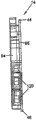
图6是图1的电信组件的右侧视图;Figure 6 is a right side view of the telecommunications assembly of Figure 1;
图7是图1的电信组件的特写图,其示出了从电信组件中分解出来的适配器组件;Figure 7 is a close-up view of the telecommunications assembly of Figure 1 showing the adapter assembly exploded from the telecommunications assembly;
图8是图1的适配器组件之一的正面透视图;Figure 8 is a front perspective view of one of the adapter assemblies of Figure 1;
图9是图8的适配器组件的背面透视图;Figure 9 is a rear perspective view of the adapter assembly of Figure 8;
图10是图8的适配器组件的右侧视图;Figure 10 is a right side view of the adapter assembly of Figure 8;
图11是图8的适配器组件的左侧视图;Figure 11 is a left side view of the adapter assembly of Figure 8;
图12是图8的适配器组件的正视图;Figure 12 is a front view of the adapter assembly of Figure 8;
图13是图8的适配器组件的后视图;Figure 13 is a rear view of the adapter assembly of Figure 8;
图14是图8的适配器组件的顶视图;Figure 14 is a top view of the adapter assembly of Figure 8;
图15是图8的适配器组件的底部视图;Figure 15 is a bottom view of the adapter assembly of Figure 8;
图16是图1的光纤分路器模块中的一个的右侧视图,其被示为带有安装于其上的适配器组件;16 is a right side view of one of the fiber optic splitter modules of FIG. 1 , shown with an adapter assembly installed thereon;
图17是图16的光纤分路器模块和适配器组件的左侧视图;Figure 17 is a left side view of the fiber optic splitter module and adapter assembly of Figure 16;
图18是图16的光纤分路器模块和适配器组件的正视图;Figure 18 is a front view of the fiber optic splitter module and adapter assembly of Figure 16;
图19是图16的光纤分路器模块和适配器组件的后视图;Figure 19 is a rear view of the fiber optic splitter module and adapter assembly of Figure 16;
图20是图16的光纤分路器模块的正面透视图,其中,以隔离的形式将其示为不带有安装于其上的适配器组件;20 is a front perspective view of the fiber optic splitter module of FIG. 16, shown in isolation without the adapter assembly installed thereon;
图21是图20的光纤分路器模块的背面透视图;Figure 21 is a rear perspective view of the fiber optic splitter module of Figure 20;
图22是图16的光纤分路器模块的分解图,其被示为带有从所述光纤分路器模块分解的适配器组件;Figure 22 is an exploded view of the fiber optic splitter module of Figure 16, shown with the adapter assembly exploded from the fiber optic splitter module;
图23是图20的光纤分路器模块的左视图;Fig. 23 is a left side view of the optical fiber splitter module of Fig. 20;
图24是图20的光纤分路器模块的右视图;Fig. 24 is the right side view of the optical fiber splitter module of Fig. 20;
图25是图20的光纤分路器模块的正视图;Figure 25 is a front view of the optical fiber splitter module of Figure 20;
图26是图20的光纤分路器模块的后视图;Figure 26 is a rear view of the fiber optic splitter module of Figure 20;
图27是图20的光纤分路器模块的顶视图;Figure 27 is a top view of the fiber optic splitter module of Figure 20;
图28是图20的光纤分路器模块的底视图;Figure 28 is a bottom view of the fiber optic splitter module of Figure 20;
图29是图20的光纤分路器模块的右视图,其被示为不带有盖,从而暴露了光纤分路器模块的内部特征,其包括光纤分路器模块内的光缆的路由;29 is a right side view of the fiber optic splitter module of FIG. 20, shown without the cover, thereby exposing the internal features of the fiber optic splitter module, including the routing of the fiber optic cables within the fiber optic splitter module;
图30是沿图29的剖面线30-30得到的截面图;Figure 30 is a cross-sectional view taken along section line 30-30 of Figure 29;
图31示出了局部插入到图1的机架内的光纤分路器模块,所述机架包括安装于其上的适配器组件,其中,在所述分路器模块的连接器接触位于所述机架内的遮板之前的位置上示出了所述光纤分路器模块;Figure 31 shows a fiber optic splitter module partially inserted into the rack of Figure 1, the rack including adapter assemblies mounted thereon, wherein the connector contacts of the splitter module are located on the The optical fiber splitter module is shown at the position before the shutter in the rack;
图32示出了图31的光纤分路器模块;其被示为,在机架内的位置上,使光纤分路器模块的连接器与位于机架内的遮板初步接触;FIG. 32 shows the fiber optic splitter module of FIG. 31; it is shown in a position within the rack with the connectors of the fiber optic splitter module in preliminary contact with shutters located within the rack;
图33示出了图31的光纤分路器模块;其被示为处于完全插入到了所述机架内的位置上;Figure 33 shows the fiber optic splitter module of Figure 31; it is shown in a position fully inserted into the rack;
图34是贯穿所述光纤分路器模块的中心得到的处于所述机架内的图32所示的光纤分路器模块的侧视截面图;Figure 34 is a side cross-sectional view of the fiber optic splitter module shown in Figure 32 in the rack taken through the center of the fiber optic splitter module;
图35是贯穿所述光纤分路器模块的中心得到的处于所述机架内的图33所示的光纤分路器模块的侧视截面图;Figure 35 is a side cross-sectional view of the fiber optic splitter module shown in Figure 33 within the rack taken through the center of the fiber optic splitter module;
图36示出了带有安装于其上的光纤分路器模块的图1所示的机架的正面透视图,其是结合从所述机架分解的防尘罩/测试工具示出的,其中,将所述防尘罩/测试工具用作测试工具;Figure 36 shows a front perspective view of the rack shown in Figure 1 with fiber optic splitter modules mounted thereon, shown with the dust cover/test tool disassembled from the rack, Wherein, the dust cover/test tool is used as a test tool;
图37示出了图36的机架的正面透视图,其是结合从所述机架分解的防尘罩/测试工具示出的,其中,将所述防尘罩/测试工具用作防尘罩;Figure 37 shows a front perspective view of the frame of Figure 36 shown with the dust cover/test tool disassembled from the frame, wherein the dust cover/test tool is used as a dust cover cover;
图38示出了图36的防尘罩/测试工具,其是结合了图8的适配器组件的分解图示出的;Figure 38 shows the dust cover/test tool of Figure 36 in conjunction with an exploded view of the adapter assembly of Figure 8;
图39是图36的防尘罩/测试工具的正面透视图,其被示为带有安装于其上的适配器组件,并且被示为带有从防尘罩/测试工具分解出的防尘罩/测试工具的测试连接器之一;Figure 39 is a front perspective view of the dust cover/test tool of Figure 36, shown with the adapter assembly mounted thereon, and with the dust cover exploded from the dust cover/test tool One of the test connectors of the /test tool;
图40是图36的防尘罩/测试工具的背面透视图,其被示为不带有防尘罩/测试工具的测试连接器;Figure 40 is a rear perspective view of the dust cover/test tool of Figure 36, shown without the test connector of the dust cover/test tool;
图41是图40的防尘罩/测试工具的正面透视图;Figure 41 is a front perspective view of the dust cover/test tool of Figure 40;
图42是图40的防尘罩/测试工具的右视图;Figure 42 is a right side view of the dust cover/test tool of Figure 40;
图43是图40的防尘罩/测试工具的左视图;Figure 43 is a left side view of the dust cover/test tool of Figure 40;
图44是图40的防尘罩/测试工具的后视图;Figure 44 is a rear view of the dust cover/test tool of Figure 40;
图45是图40的防尘罩/测试工具的顶视图;Figure 45 is a top view of the dust cover/test tool of Figure 40;
图46是根据本发明的夹紧延伸部的底部正面透视图;Figure 46 is a bottom front perspective view of a clamping extension according to the present invention;
图47是图46的夹紧延伸部的底部背面透视图;Figure 47 is a bottom rear perspective view of the clamping extension of Figure 46;
图48是图46的夹紧延伸部的底视图;Figure 48 is a bottom view of the clamping extension of Figure 46;
图49是图46的夹紧延伸部的顶视图;Figure 49 is a top view of the clamping extension of Figure 46;
图50是图46的夹紧延伸部的右视图;Figure 50 is a right side view of the clamping extension of Figure 46;
图51是图46的夹紧延伸部的左视图;以及Figure 51 is a left side view of the clamping extension of Figure 46; and
图52是图46的夹紧延伸部的后视图。FIG. 52 is a rear view of the clamping extension of FIG. 46. FIG.
具体实施方式Detailed ways
现在将详细参考在附图中示出的本发明的示范性方面。只要可能,将在所有的附图中采用相同的附图标记表示相同或类似的部分。Reference will now be made in detail to the exemplary aspects of the invention illustrated in the accompanying drawings. Wherever possible, the same reference numbers will be used throughout the drawings to refer to the same or like parts.
图1-7示出了电信组件10,其包括电信机架12和适于安装在所述机架12内的多个光纤分路器模块14。将光纤分路器模块14配置为以可滑动的方式插入到机架12内,并且可以被光学耦合至安装在机架12内的适配器组件16。安装在机架12内的适配器组件16形成了在端接至输入光缆的连接器和分路器模块14的连接器之间的连接位置,在下文中将对其给出更为详细的讨论。1-7 illustrate a
仍然参考图1-7,机架12包括在一对相对的横向侧壁22和24之间延伸的顶壁18和底壁20。机架12包括通过机架12的背面28的开口26和通过机架12的正面32的开口30。将光纤分路器模块14通过正面开口30插入到机架12内。将适配器组件16通过机架12的背面开口26插入并邻近所述开口安装。侧壁22和24均包括从所述正面开口30朝向背面28延伸的切口34。通过所述切口34可以看到安装在所述机架12内的分路器模块14。所述机架12的侧壁22和24还限定了处于所述机架12的背面28的插入部分36,其有助于触及适配器组件16。Still referring to FIGS. 1-7 , the
在图1中,机架12被示为具有安装于其上的八个光纤分路器模块14。应当指出,在其他实施例中,可以将机架的尺寸设为容纳更多或更少的分路器模块。In FIG. 1 , a
仍然参考图1-7,机架12包括用于以滑动的方式接收分路器模块14的多个安装位置38。每一安装位置38限定了与机架12的顶壁18相邻的插槽40和与机架12的底壁20相邻的插槽42。在图1中可以看到与底壁20相邻的插槽42。在图36和37中示出了与顶壁18相邻的插槽40。插槽40和42从机架12的正面32延伸至机架12的背面28。将插槽40和42配置为接收如图36和37所示的分路器模块14的安装凸缘44和46,从而使模块14与机架12内的其他部件(例如,适配器组件的适配器)对准,进而与预先连接器化的和/或预先安装的传输光缆配合。Still referring to FIGS. 1-7 , the
在机架12的顶壁18的下面限定的插槽40比在机架12的底壁20上限定的插槽42深。将插槽40和42的深度配置为容纳在分路器模块14的顶壁和底壁上限定的不同尺寸的凸缘44和46。通过这种方式,插槽40和42以及光纤分路器模块14的安装凸缘44和46提供了确保将模块14按照正确的朝向插入到机架12内的锁定机制。The
机架12的顶壁18下面的插槽40限定于多个隔板(bulkhead)48之间(参考图36和37)。隔板48从机架12的正面32延伸至机架12的背面28。在机架12的前端32处,每一隔板48限定了向下延伸的前唇板50(图35),其与分路器模块14的带有回弹力的可形变闭锁件52(例如悬臂)联锁,从而使分路器模块14在机架12内固定就位,这一点将在下文中更为详细地讨论。
参考图1和图7,在机架12的后端28处,每一隔板48限定了背面54,其带有用于接收适配器组件16的紧固件58(例如,指旋螺丝)的紧固件孔56,从而将适配器组件16安装到机架12上。在图示的实施例中,使紧固件孔56带有螺纹,以接收螺丝型紧固件。应当指出,在其他实施例中,可以采用其他类型的紧固结构将适配器组件16安装到机架12的背面28。Referring to FIGS. 1 and 7 , at the
在与后端28相邻的位置,每一隔板48还包括水平插槽60和竖直插槽62,它们与适配器组件16的形状互补,从而滑动接收适配器组件16。Adjacent the
图8-15示出了根据本发明的适配器组件16。适配器组件16在端接至输入光缆的连接器和安装在机架12内的分路器模块14的连接器之间形成了连接位置。8-15 illustrate an
参考图8-15,适配器组件16包括被形成为整体式外壳66的一部分的两个集成适配器64。在其他实施例中,也可能采用其他数量的适配器。适配器组件16的每一适配器64包括前端68和后端70。每一适配器64的前端68接收光纤分路器模块14的连接器,后端70接收端接至输入光缆的连接器。Referring to FIGS. 8-15 , the
适配器组件外壳66包括从外壳66的顶部74延伸的机架安装滑块72,其通过后端28容纳于机架12内。滑块72限定了水平部分76和竖直部分78。将水平部分76配置为以可滑动的方式容纳于隔板48的水平插槽60内,将竖直部分78配置为以可滑动的方式容纳于隔板48的竖直插槽62内。The
机架安装滑块72包括一对凸缘80,其用于支持紧固件58,从而将适配器组件16固定至机架12。如前所述,将紧固件58置于由位于机架12的顶壁18的下面的隔板48的背面54限定的开口56内。紧固件58优选为系留紧固件。在如图所示的适配器组件的实施例中,紧固件58为指旋螺丝,在其他实施例中,可以采用其他类型的紧固件。
使紧固件58发生旋转从而借助螺纹将适配器组件16连接至隔板48。还将紧固件58配置为,一旦将适配器组件16安装到机架12上,其能够为适配器组件16提供相对于机架12的预定量的水平浮动。如图8-14所示,适配器组件16的紧固件58包括凸缘81。紧固件58能够相对于适配器组件外壳66在凸缘80内水平移动。如图35所示,一旦安装到了机架12上,适配器组件外壳66能够在凸缘81和隔板48的背面之间相对于紧固件58水平浮动或移动。例如,在图35中,适配器组件16被示为能够朝向机架12的后端移动或浮动距离A。通过这种方式,当在拆卸过程中将分路器模块14从机架12中以滑动的方式拉出时,随着分路器14的啮合的连接器118拉紧适配器组件16的适配器64,适配器组件16能够朝向分路器模块14浮动距离A。通过这种方式,为适配器组件16提供了在啮合至分路器模块14或从其上拆下时产生的一定量的水平浮动。
如图38中的适配器组件16的分解图所示,通过侧面开口82将每一适配器64的元件置入到形成于适配器组件外壳66内的适配器凹陷84内。每一适配器64的元件包括箍圈对准套筒86和一对内部半壳体88。通过与1993年5月20日颁发的名为“ONE-PIECE SC ADAPTER”的为本申请人所共有美国专利No.5317663所公开的类似的方式将这些元件置入到凹陷84内,在此将其公开内容引入以供参考。面板90关闭开口82,并保护每一适配器64内的元件。所示的适配器64是用于SC样式的连接器的,但是在本公开的范围内也可以采用其他类型、样式和形式的适配器以及与这些备选适配器配合的连接器。As shown in the exploded view of
在图16-19中,将适配器组件16示为在机架12之外安装到光纤分路器模块14上。In FIGS. 16-19 , the
图20-30示出了根据本发明的光纤分路器模块14中的一个。参考图20-30,光纤分路器模块14包括分路器模块外壳92。分路器模块外壳92包括主壳体部分94和可卸盖96。主壳体部分94包括在顶壁100、底壁102、后壁104和前壁106之间延伸的第一横向侧壁98。可卸盖96限定了分路器模块外壳92的第二横向壁108,并且关闭了模块主壳体94的开口侧。20-30 illustrate one of the fiber
通过使紧固件(未示出)穿过限定于主壳体部分94上的紧固件底座110将盖96安装到主壳体部分94上。盖96延伸到第一横向壁98之外,以形成分路器模块14的顶部安装凸缘44和底部安装凸缘46。参考图23、25和26,如上所述,分路器模块外壳92的底部凸缘46和机架12上的对应插槽42在尺寸上小于顶部凸缘44和机架12上的对应插槽40。将底部插槽42的尺寸设置为,可以将底部凸缘46容纳于插槽42内,而较大的顶部凸缘44则不匹配。其确保了将模块14按照特定的预期取向置于正面开口30内。在1994年11月8日颁发的名为“FIBER OPTIC CONNECTOR MODULE”的共有美国专利No.5363465中描述了类似的凸缘,在此将其公开内容引入以供参考,通过这种方式,将光纤模块14按照正确的取向在每一安装位置38连接至邻近机架12的背面28安装的适配器组件16。
主壳体部分94的后壁104包括曲面部分112,其被配置为为内部114之内的光缆提供弯曲半径保护。主壳体92的后壁104还包括插入部分116。置于插入部分116处的一对光纤连接器118从后壁104向后突出,从而与安装在机架12内的适配器组件16的光纤适配器64配合。The
如图5和图6所示,使模块主壳体94的前壁106相对于机架12的正面开口30成一定角度,其有助于光缆处于有利的方向,从而使朝向预期的位置离开模块14。在其他实施例中,在本公开的范围内,可以使前壁106大致平行于机架12的正面32。As shown in FIGS. 5 and 6 , angling the
每一模块14包括两个从模块主壳体94的前壁106延伸的光缆出口120。如图22所示,将光缆出口120可滑动安装到模块14的主壳体94上,并且在将盖96安装到主壳体94上时,使模块14的盖96俘获光缆出口120。光缆出口120限定了突出的后唇板122,其可以滑动插入到围绕前窗孔126限定的用于容纳光缆出口120的插槽124内。盖96还包括狭缝128,其接收光缆出口120的后唇板122,以俘获光缆出口120。光缆出口120允许将模块14内的电信光缆引出到模块14之外。如图25所示,优选将光缆出口120的尺寸设置为足够薄,以匹配到光纤分路器模块14的轮廓内,并由此保持电信组件10的密度。Each
主壳体94包括整体形成的柔性闭锁件52(即,悬臂),其适于啮合机架12的一部分,从而将模块14固定到机架12的正面开口30内。柔性闭锁件52还可以发生偏转,从而允许将模块14从机架12上拆卸下来。The
仍然参考图20-30,模块14的闭锁件52包括指状夹紧突起130、前闭锁突起132和后闭锁突起134。前闭锁突起132和后闭锁突起134在其间限定了凹陷136。后闭锁突起134包括倾斜面138,在将模块14插入到机架12内时,所述倾斜面138使闭锁件52向下发生弹性偏转。后闭锁突起134还包括方形面140,其与前闭锁突起132的方形面142相对。Still referring to FIGS. 20-30 , the
在两个闭锁突起132和134之间的凹陷136内俘获处于机架12的安装位置38上的隔板48的前唇板50,从而使模块14在机架12内固定就位。在插入过程中,随着隔板48的前唇板50越过倾斜的后突起134,并被俘获在两个闭锁突起132和134之间的凹陷136内,闭锁件52将向上回弹。闭锁件52的两个突起132和134之间的凹陷136允许分路器模块14在机架12内发生一定量的水平浮动,在下文中将对其做进一步讨论。The
通过向下按闭锁件52,使后突起134的方形面140脱离唇板50,并使模块14滑出机架12来执行模块14的拆卸。模块14包括固定的夹紧突起144,其与柔性闭锁件52相对并与之相邻,从而有助于将模块14从机架12上拆下。将固定的夹紧突起144形成为模块14的前壁106的一部分。优选将固定的夹紧突起144置于模块14上与闭锁件52相对的位置,从而使用户可以对闭锁件52和固定的夹紧突起144施加相对的力,从而牢固地夹紧模块14,以及将其从机架12上拆除。优选将固定的夹紧突起144置于模块14上的足够接近闭锁件52的位置,从而使用户可以用两个相邻的手指施加力。Removal of the
图22示出了说明模块14的内部部件的光纤分路器模块14的分解图。在图22中将光纤分路器模块14示为带有从模块14上分解出来的适配器组件16。FIG. 22 shows an exploded view of the fiber
在主壳体94的内部114之内,分路器模块14包括与主壳体94的后壁104的曲面部分122相邻的第一半径限制器146。分路器模块14包括与接近光缆出口120的外壳94的前壁106相邻的第二半径限制器148。将分路器模块14的连接器118可滑动插入到形成于后壁104上的窗孔156内的相对插槽154内。连接器118在后壁104的插入部分116处从后壁104突出。连接器118的外壳150包括容纳于相对的插槽154内的横向凸缘152,所述相对的插槽154形成于用于容纳连接器118的窗孔156内。一旦将连接器118可滑动插入,盖96就会将连接器118俘获到外壳92内。Within the interior 114 of the
诸如光纤分路器或扇出端的光学部件158与内部114内的主壳体94的底壁102相邻。通过夹板160(即托架)使光学部件158紧靠底壁102的内部固定。借助紧固件(未示出)将夹板160安装到限定于分路器模块主壳体94上的夹板底座162上。在如图所示的外壳94的实施例中,夹板底座162包括两对安装孔164和166。根据用于将光学部件158固定到底壁102上的夹板的尺寸采用上面的一组孔164或下面的一组孔166。应当注意,不同的光学部件可以具有不同的厚度,并且可能需要采用不同尺寸的夹板将光学部件固定就位。在某些实施例中,可以采用一个叠在另一个上的两个光学部件,在这种情况下,可以采用较小的夹板将所述两个光学部件固定就位。
通过一组光缆管理结构168使光学部件158从第一横向壁98的内部一侧发生偏移。在图示的模块14的实施例中,所述的一组光缆管理结构168是在其间限定了光缆管理狭缝172的细长结构170。在将光学部件158固定就位时,可以使光缆通过光学部件158和第一横向壁98的内侧之间的狭缝172路由(请参考图29和30)。The
分路器模块主壳体94还包括位于第二半径限制器148之下与外壳94的前壁106相邻的作为整体形成的压接(crimp)支架174(例如,插槽)。如图22和29所示,将压接至通过光学部件158拆分的光缆的末端的压接元件176可滑动容纳到压接支架174内。压接元件176限定了方形凸缘175,在方形凸缘175之间限定了凹陷部分177。压接支架174包括与压接元件互补的结构,从而在将压接元件176可滑动插入到压接支架174内之后,在凸缘175的作用下避免压接元件176沿纵向移动。一旦将压接元件176滑动插入之后,就通过安装到分路器模块主壳体94上的盖96将压接元件176固定就位。在图示的实施例中,有九个压接固定插槽174,每一插槽能够容纳多达四个压接元件176。其他数量也是可能的。也可能采用其他压接元件和压接固定插槽之间的互补外形提供滑动匹配,并且在将压接元件插入到压接支架内之后避免压接元件发生轴向移动。The splitter module
图29示出了不带盖96的光纤分路器模块14,其暴露了包括光缆在光纤分路器模块14内的路由的光纤分路器模块14的内部特征。图30是沿图29的剖面线30-30得到的截面图。FIG. 29 shows the fiber
如图29所示,第一光缆178从连接器118朝向安装在模块外壳92内的光学部件158延伸。如前面讨论的,光学部件158可以是分路器、扇出端或者其他类型的光学部件。在图示的实施例中,光学部件158是用于将单股的信号拆分成多个次级信号的光纤分路器。在另一实施例中,第一光缆178可以是带有多股光纤的多股光缆,所述光学部件可以是用于将各个股分离成多个第二光缆中的每一个的扇出端。As shown in FIG. 29 , a first
随着第一光缆178朝向光学部件158延伸,将所述第一光缆178通过光学部件158和模块外壳94的第一横向壁98的内侧之间的狭缝172(参考图22、29和30)插入,并使其环绕第一半径限制器146,之后在被光学部件158接收之前环绕第二半径限制器148。第二光缆180从光学部件158开始延伸,并且在通往压接支架174之前也一直环绕第一半径限制器146。压接至压接元件176的其他末端的光缆(未示出)从压接支架174通过模块出口120离开所述模块。As the first
外部光缆(未示出)可以延伸至适配器组件16的适配器64的后端70,并端接于连接器(图29中未示出),在将模块14插入到机架12内后,所述连接器通过适配器64光学连接至模块14的连接器118。应当指出,如图29和30所示的光纤光缆在模块14内的路由只是一个例子,也可能采用光缆在所述模块内的其他路由方式。An external fiber optic cable (not shown) may extend to the
将如图所示的光纤分路器模块14的实施例配置为使其能够容纳降低的弯曲半径光纤。降低的弯曲半径光纤可以具有大约15mm的弯曲半径,而未降低的弯曲半径光纤可以具有大约30mm的弯曲半径。The embodiment of the fiber
在本申请人共有的美国专利申请No.10980978(2004年11月3日提交,名为“FIBER OPTIC MODULE AND SYSTEM INCLUDING REAR CONNECTORS”);11/138063(2005年5月25日提交,名为“FIBER OPTIC SPLITTER MODULE”);11/138889(2005年5月25日提交,名为“FIBER OPTIC ADAPTER MODULE”);以及11/215837(2005年8月29日提交,名为“FIBER OPTIC SPLITTER MODULE WITH CONNECTOR ACCESS”)中描述了类似的光纤分路器模块,在此将其公开内容引入以供参考。U.S. Patent Application No. 10980978 (filed November 3, 2004, entitled "FIBER OPTIC MODULE AND SYSTEM INCLUDING REAR CONNECTORS"); 11/138063 (filed May 25, 2005, entitled " FIBER OPTIC SPLITTER MODULE"); 11/138889 (filed May 25, 2005, titled "FIBER OPTIC ADAPTER MODULE"); and 11/215837 (filed August 29, 2005, titled "FIBER OPTIC SPLITTER MODULE WITH CONNECTOR ACCESS"), the disclosure of which is incorporated herein by reference.
在图31-35中示出了分路器模块14向机架12内的插入。参考图31-35,光纤模块14向机架12的正面开口30内的插入开始于模块14向机架12以及向适配器组件16的适配器64的配合。随着模块14的插入,顶部凸缘44啮合机架12的顶部插槽40,底部凸缘46啮合机架12的底部插槽42。Insertion of the
仍然参考图31-35,机架12包括处于每一安装位置38上的柔性遮板182。遮板182适于避免意外暴露于光下。将遮板182置于适配器组件16的每一适配器64的前端68。在将分路器模块14放在相关的安装位置38上之前,如果连接至适配器组件16的适配器64的带有连接器的光缆受到了照明并且传输光信号,那么遮板182将避免意外暴露至这些信号之下,因为这些信号可能损害眼睛或其他敏感器官或者损害附近的通信设备。如图31-33所示,分路器模块14的插入将遮板182推开。Still referring to FIGS. 31-35 , the
随着模块14通过正面开口30插入,遮板182在模块14的作用下发生偏转,从而使模块14的连接器118能够与适配器组件16的适配器64配合。遮板182优选由可弹性变形的材料构成,在将模块14从安装位置38退出时,其将返回到所述位置。As the
例如,在图31中,将光纤分路器模块14示为在分路器模块14的连接器118接触机架12的遮板182之前部分插入到机架12内。在图32中,将光纤分路器模块14示为处于机架12内的位置上,其中,光纤分路器模块14的连接器118初始接触机架12的遮板182,从而将遮板182移开(图34中示出了侧视截面图)。在图33中,将光纤分路器模块14示为处于机架12内的完全插入的位置上,这时已经将遮板182移开了(图35中示出了侧视截面图)。For example, in FIG. 31 , the fiber
将遮板182配置为,在连接器118接触遮板182从而将其移开时,遮板182不与分路器模块14的连接器118的箍圈184啮合。相反,外侧的连接器外壳150会将遮板182推开。The
可以通过紧固件将遮板182连接至机架12,或者作为替代,可以将遮板182与机架12作为一体形成,或者通过点焊或其他紧固技术安装遮板182。The
随着遮板182完全偏转,模块14的进一步插入将使连接器118与适配器64接触,并使连接器118容纳于适配器64的前端68内。随着模块14的插入,闭锁件52向内偏转,之后回弹,从而使隔板48的前唇板50被俘获在凹陷136内。现在,模块14已经处于了能够通过模块内部114内的第一光缆178、光学部件158和第二光缆180处理和传输来自光缆的信号的位置。With the
参考图35,如上所述,闭锁件52的两个突起132和134之间的凹陷136为分路器模块14提供了在机架12内的一定量的水平浮动。如图35所示,在隔板48的前唇板50接触后突起134的方形面140之前,允许所述前唇板50移动距离D。将分路器模块14配置为,在将分路器模块14从机架12的前面32拉出时,隔板48的前唇板50在接触后突起134的方形面140之前所经过的距离D小于如上文讨论的为适配器组件16提供的水平浮动(即,距离A)。Referring to FIG. 35 , as described above, the
通过这种方式,分路器模块14提供了一种保护形式,其能够避免模块的连接器118从机架12的背面28上的适配器组件16意外脱落。将模块14的凹陷136的尺寸配置为,在将适配器组件16朝向机架12的正面拉出足够远的距离,从而使其水平运动停止并使模块14的连接器118从适配器64意外脱落之前中断分路器模块14的水平浮动。In this way, the
图36-45示出了被配置为与电信组件10的适配器组件16结合使用的防尘罩/测试工具190。防尘罩/测试工具190包括带有前端194和后端196的主体192。防尘罩/测试工具190包括一对从前端194突出的连接器118。如图39所示,将一对连接器118滑动插入到防尘罩/测试工具190的主体192的连接器支架193内。与在分路器模块14的外壳94中一样,连接器支架193包括用于容纳连接器118的外壳的凸缘的插槽195。防尘罩/测试工具190还包括一对从后端196突出的防尘塞198。防尘罩/测试工具190包括顶壁200和底壁202以及第一横向侧面204和第二横向侧面206。顶壁和底壁200和202分别包括滑动插入到机架12内的顶部和底部凸缘208和210,这与光纤分路器模块14类似。第一横向侧面204包括用于引导端接于防尘罩/测试工具190的连接器118的光缆的半径限制器212。在前端194处存在与主体192作为整体形成的第一夹钳214。在防尘罩/测试工具190的后端196处,存在限定于与主体192作为整体形成的半径限制器212的末端的第二夹钳216。36-45 illustrate a dust cover/
如图36和37所示,将防尘罩/测试工具190可滑动插入到机架12内,并且可以按照两种不同的方式对其加以利用。在图36中,将防尘罩/测试工具190示为被用作测试工具,以测试输入到适配器组件16内的光学信号。由于适配器组件16位于机架的后端28,适配器组件16的适配器64的前端68位于后端28处的机架12的内部,因而变得难以触及所述连接,以实现测试或其他目的。将防尘罩/测试工具190的前端194上的一对连接器118设计为在将防尘罩/测试工具190可滑动插入到机架12内时连接至适配器组件16的适配器64。通过这种方式,可以在不将适配器组件16从机架12上拆下,并且无需进入机架12的情况下测试适配器组件16处的连接。As shown in Figures 36 and 37, the dust cover/
如图37所示,可以使防尘罩/测试工具190翻转180°,并将其用作防尘罩,以密封适配器64的内部,避免污染物的影响。如果不将分路器模块14插入到机架12的安装位置38之一内,防尘罩/测试工具190可以起到占位器的作用,并且可以被滑动插入到机架12内。防尘塞198包括凹陷部分199,其用于容纳处于适配器64内部的半壳体的臂91的突出突起89。凹陷部分199有助于使防尘塞保持在适配器64之内。As shown in Figure 37, the dust cover/
在图38中,示出了防尘罩/测试工具190与分解出的适配器组件16结合。在图39中,防尘罩/测试工具190被示为带有安装于其上的适配器组件16,并且被示为带有从防尘罩/测试工具190中分解出来的防尘罩/测试工具190的测试连接器118之一。In Fig. 38, the dust cover/
图46-52示出了适于与连接至适配器组件16的适配器64的背面70的连接器118结合使用的夹紧延伸部218。将夹紧延伸部218设计为增加连接器118的外壳150的长度,从而有助于在诸如电信组件10的密集环境下触及各个连接器118。优选在使光缆端接于连接器118之前,首先将夹紧延伸部安装到光缆上。一旦使连接器118端接于光缆,就使夹紧延伸部218滑过连接器的保护罩(boot)220,并安装到连接器118的外壳150上,如图7所示。46-52 illustrate a
参考图46-52,夹紧延伸部218包括伸长体222,其带有四个从伸长体222的正面部分224延伸出来的四个悬臂。两个相对的悬臂226和228包括用于与连接器118的外壳150的夹紧表面232啮合的突出翼片230。另外两个相对的悬臂234和236包括用于啮合限定于连接器外壳150上的凸缘240的狭缝238。借助四个悬臂226、228、234和236,将夹紧延伸部218卡扣配合到连接器外壳150上。夹紧延伸部主体222的背面部分242包括顶侧244、开放的底侧246和两个沿从正面224到背面242的方向呈锥形的横向侧248和250。顶侧和底侧244和246包括夹紧结构252,以有助于拉动夹紧延伸部218,以拆除连接器118。Referring to FIGS. 46-52 , the clamping
上述说明、实例和数据提供了对本发明的制造和使用的完整说明。由于在不背离本发明的精神和范围的情况下可以实施很多本发明的实施例,因而本发明涵盖于权利要求的范围内。The above specification, examples and data provide a complete description of the manufacture and use of the invention. Since many embodiments of the invention can be made without departing from the spirit and scope of the invention, the invention lies in the scope of the following claims.
Claims (22)
Applications Claiming Priority (2)
| Application Number | Priority Date | Filing Date | Title |
|---|---|---|---|
| US11/354,297 | 2006-02-13 | ||
| US11/354,297 US7418181B2 (en) | 2006-02-13 | 2006-02-13 | Fiber optic splitter module |
Related Parent Applications (1)
| Application Number | Title | Priority Date | Filing Date |
|---|---|---|---|
| CN2007800052521A Division CN101384938B (en) | 2006-02-13 | 2007-02-06 | Fiber Splitter Module |
Publications (2)
| Publication Number | Publication Date |
|---|---|
| CN102087392A true CN102087392A (en) | 2011-06-08 |
| CN102087392B CN102087392B (en) | 2013-11-06 |
Family
ID=38042757
Family Applications (2)
| Application Number | Title | Priority Date | Filing Date |
|---|---|---|---|
| CN2007800052521A Expired - Fee Related CN101384938B (en) | 2006-02-13 | 2007-02-06 | Fiber Splitter Module |
| CN2011100541687A Expired - Fee Related CN102087392B (en) | 2006-02-13 | 2007-02-06 | Fiber optic splitter module |
Family Applications Before (1)
| Application Number | Title | Priority Date | Filing Date |
|---|---|---|---|
| CN2007800052521A Expired - Fee Related CN101384938B (en) | 2006-02-13 | 2007-02-06 | Fiber Splitter Module |
Country Status (13)
| Country | Link |
|---|---|
| US (11) | US7418181B2 (en) |
| EP (1) | EP1987383B1 (en) |
| JP (1) | JP5209503B2 (en) |
| KR (1) | KR101459158B1 (en) |
| CN (2) | CN101384938B (en) |
| AR (1) | AR059572A1 (en) |
| AU (1) | AU2007215468B2 (en) |
| BR (1) | BRPI0707734A8 (en) |
| DK (1) | DK1987383T3 (en) |
| ES (1) | ES2539428T3 (en) |
| PL (1) | PL1987383T3 (en) |
| TW (1) | TWI429973B (en) |
| WO (1) | WO2007094987A2 (en) |
Cited By (1)
| Publication number | Priority date | Publication date | Assignee | Title |
|---|---|---|---|---|
| CN111164482A (en) * | 2017-06-28 | 2020-05-15 | 康宁研究与开发公司 | Multiports and other devices having connection ports with fixed features |
Families Citing this family (198)
| Publication number | Priority date | Publication date | Assignee | Title |
|---|---|---|---|---|
| US6885798B2 (en) | 2003-09-08 | 2005-04-26 | Adc Telecommunications, Inc. | Fiber optic cable and furcation module |
| GB0402187D0 (en) | 2004-01-31 | 2004-03-03 | Tyco Electronics Raychem Nv | A crimp for an optical cable connector |
| US7400813B2 (en) | 2005-05-25 | 2008-07-15 | Adc Telecommunications, Inc. | Fiber optic splitter module |
| KR101442261B1 (en) | 2005-07-15 | 2014-09-22 | 어번 유니버시티 | Microscope illumination device and adapter for dark and bright-field illumination |
| US7623749B2 (en) | 2005-08-30 | 2009-11-24 | Adc Telecommunications, Inc. | Fiber distribution hub with modular termination blocks |
| JP3987078B2 (en) * | 2005-08-31 | 2007-10-03 | 日本電信電話株式会社 | Optical connector |
| US7245809B1 (en) * | 2005-12-28 | 2007-07-17 | Adc Telecommunications, Inc. | Splitter modules for fiber distribution hubs |
| US7418181B2 (en) | 2006-02-13 | 2008-08-26 | Adc Telecommunications, Inc. | Fiber optic splitter module |
| US7816602B2 (en) | 2006-02-13 | 2010-10-19 | Adc Telecommunications, Inc. | Fiber distribution hub with outside accessible grounding terminals |
| US7711234B2 (en) * | 2006-10-02 | 2010-05-04 | Adc Telecommunications, Inc. | Reskinnable fiber distribution hub |
| US7689089B2 (en) * | 2006-10-11 | 2010-03-30 | Panduit Corp. | Release latch for pre-terminated cassette |
| US7349616B1 (en) | 2007-01-12 | 2008-03-25 | Corning Cable Systems Llc | Fiber optic local convergence points for multiple dwelling units |
| US7493002B2 (en) | 2007-01-19 | 2009-02-17 | Adc Telecommunications, Inc. | Fiber optic adapter cassette and panel |
| US7522805B2 (en) * | 2007-03-09 | 2009-04-21 | Adc Telecommunications, Inc. | Wall mount distribution arrangement |
| JP4343238B2 (en) * | 2007-05-29 | 2009-10-14 | 日本航空電子工業株式会社 | Assembly |
| US7734138B2 (en) * | 2007-05-30 | 2010-06-08 | Corning Cable Systems Llc | Fiber optic connector holders |
| US7590328B2 (en) | 2007-08-02 | 2009-09-15 | Adc Telecommunications, Inc. | Fiber termination block with splitters |
| US7885505B2 (en) | 2007-10-22 | 2011-02-08 | Adc Telecommunications, Inc. | Wavelength division multiplexing module |
| US7536075B2 (en) * | 2007-10-22 | 2009-05-19 | Adc Telecommunications, Inc. | Wavelength division multiplexing module |
| CN101836148B (en) * | 2007-10-22 | 2014-04-16 | Adc电信公司 | Fiber distribution hub |
| US7751672B2 (en) | 2007-10-31 | 2010-07-06 | Adc Telecommunications, Inc. | Low profile fiber distribution hub |
| US8229265B2 (en) | 2007-11-21 | 2012-07-24 | Adc Telecommunications, Inc. | Fiber distribution hub with multiple configurations |
| US8238709B2 (en) | 2007-12-18 | 2012-08-07 | Adc Telecommunications, Inc. | Multi-configuration mounting system for fiber distribution hub |
| US8107816B2 (en) * | 2008-01-29 | 2012-01-31 | Adc Telecommunications, Inc. | Wavelength division multiplexing module |
| US8270796B2 (en) * | 2008-03-04 | 2012-09-18 | Adc Telecommunications, Inc. | Multi-port adapter block |
| US7715682B2 (en) * | 2008-03-04 | 2010-05-11 | Adc Telecommunications, Inc. | Fiber distribution hub having an adjustable plate |
| US20100322583A1 (en) | 2009-06-19 | 2010-12-23 | Cooke Terry L | High Density and Bandwidth Fiber Optic Apparatuses and Related Equipment and Methods |
| AU2015203580A1 (en) * | 2008-08-29 | 2015-07-23 | Corning Optical Communications LLC | Rear-installable fiber optic modules and equipment |
| US8184938B2 (en) | 2008-08-29 | 2012-05-22 | Corning Cable Systems Llc | Rear-installable fiber optic modules and equipment |
| US11294136B2 (en) | 2008-08-29 | 2022-04-05 | Corning Optical Communications LLC | High density and bandwidth fiber optic apparatuses and related equipment and methods |
| US8452148B2 (en) | 2008-08-29 | 2013-05-28 | Corning Cable Systems Llc | Independently translatable modules and fiber optic equipment trays in fiber optic equipment |
| US8573855B2 (en) * | 2008-10-06 | 2013-11-05 | Adc Telecommunications, Inc. | Fanout cable assembly and method |
| WO2010059623A1 (en) * | 2008-11-21 | 2010-05-27 | Adc Telecommunications, Inc. | Fiber optic telecommunications module |
| US8428418B2 (en) * | 2008-12-09 | 2013-04-23 | Adc Telecommunications, Inc. | Fiber optic adapter plate and cassette |
| WO2010083369A1 (en) | 2009-01-15 | 2010-07-22 | Adc Telecommunications, Inc. | Fiber optic module, chassis and adapter |
| EP2221932B1 (en) | 2009-02-24 | 2011-11-16 | CCS Technology Inc. | Holding device for a cable or an assembly for use with a cable |
| EP3399672B1 (en) | 2009-03-05 | 2022-07-27 | CommScope Technologies LLC | Methods, systems and devices for integrating wireless technology into a fiber optic network |
| US8699838B2 (en) | 2009-05-14 | 2014-04-15 | Ccs Technology, Inc. | Fiber optic furcation module |
| TWI471621B (en) * | 2009-05-20 | 2015-02-01 | Sumitomo Electric Industries | Splitter module |
| US9075216B2 (en) | 2009-05-21 | 2015-07-07 | Corning Cable Systems Llc | Fiber optic housings configured to accommodate fiber optic modules/cassettes and fiber optic panels, and related components and methods |
| US8538226B2 (en) | 2009-05-21 | 2013-09-17 | Corning Cable Systems Llc | Fiber optic equipment guides and rails configured with stopping position(s), and related equipment and methods |
| US7899300B2 (en) * | 2009-06-03 | 2011-03-01 | Emerson Network Power, Energy Systems, North America, Inc. | Dust caps for fiber optic connectors |
| US8244089B2 (en) * | 2009-06-03 | 2012-08-14 | Emerson Network Power, Energy Systems, North America, Inc. | Dust caps for fiber optic connectors |
| CN102804014A (en) | 2009-06-19 | 2012-11-28 | 康宁电缆系统有限责任公司 | High fiber optic cable packing density apparatus |
| US8712206B2 (en) | 2009-06-19 | 2014-04-29 | Corning Cable Systems Llc | High-density fiber optic modules and module housings and related equipment |
| CA2765835A1 (en) * | 2009-06-22 | 2011-01-13 | Corning Cable Systems Llc | Fiber optic cable parking device |
| ES2403007A1 (en) * | 2009-07-01 | 2013-05-13 | Adc Telecommunications, Inc | Wall-mounted fiber distribution hub |
| US8346047B2 (en) * | 2009-08-13 | 2013-01-01 | Commscope, Inc. Of North Carolina | Fiber management component |
| US8606067B2 (en) * | 2009-09-04 | 2013-12-10 | Adc Telecommunications, Inc. | Pedestal terminal with swing frame |
| US8714368B2 (en) * | 2009-09-09 | 2014-05-06 | Adc Telecommunications, Inc. | Pass-through trough |
| US8428419B2 (en) * | 2009-09-23 | 2013-04-23 | Adc Telecommunications, Inc. | Fiber distribution hub with internal cable spool |
| US8515234B2 (en) * | 2009-11-25 | 2013-08-20 | Adc Telecommunications, Inc. | Methods, systems and devices for providing fiber-to-the-desktop |
| US20110129185A1 (en) * | 2009-11-30 | 2011-06-02 | Lewallen C Paul | Articulated Strain Relief Boot on a Fiber Optic Module and Associated Methods |
| US8625950B2 (en) | 2009-12-18 | 2014-01-07 | Corning Cable Systems Llc | Rotary locking apparatus for fiber optic equipment trays and related methods |
| US8498510B2 (en) * | 2010-01-18 | 2013-07-30 | Adc Telecommunications, Inc. | Fiber distribution enclosure |
| US8824850B2 (en) * | 2010-01-26 | 2014-09-02 | Adc Telecommunications, Inc. | Insect-infestation prevention device for a telecommunications equipment housing |
| US8593828B2 (en) * | 2010-02-04 | 2013-11-26 | Corning Cable Systems Llc | Communications equipment housings, assemblies, and related alignment features and methods |
| WO2011107180A1 (en) | 2010-03-02 | 2011-09-09 | Adc Gmbh | Fibre-optic telecommunication module |
| US8649649B2 (en) | 2010-03-03 | 2014-02-11 | Adc Telecommunications, Inc. | Fiber distribution hub with connectorized stub cables |
| US20110235986A1 (en) * | 2010-03-24 | 2011-09-29 | Adc Telecommunications, Inc. | Optical fiber drawer with connectorized stub cable |
| US8913866B2 (en) | 2010-03-26 | 2014-12-16 | Corning Cable Systems Llc | Movable adapter panel |
| US8837940B2 (en) | 2010-04-14 | 2014-09-16 | Adc Telecommunications, Inc. | Methods and systems for distributing fiber optic telecommunication services to local areas and for supporting distributed antenna systems |
| US9078287B2 (en) | 2010-04-14 | 2015-07-07 | Adc Telecommunications, Inc. | Fiber to the antenna |
| CN102884469B (en) | 2010-04-16 | 2016-09-28 | Ccs技术股份有限公司 | Sealing and strain relief means for data cable |
| EP2381284B1 (en) | 2010-04-23 | 2014-12-31 | CCS Technology Inc. | Under floor fiber optic distribution device |
| CN102971653B (en) * | 2010-04-27 | 2015-04-22 | 爱德龙通讯系统(上海)有限公司 | Fiber Optic Modules and Enclosures |
| US9632270B2 (en) | 2010-04-30 | 2017-04-25 | Corning Optical Communications LLC | Fiber optic housings configured for tool-less assembly, and related components and methods |
| US8660397B2 (en) | 2010-04-30 | 2014-02-25 | Corning Cable Systems Llc | Multi-layer module |
| US9075217B2 (en) | 2010-04-30 | 2015-07-07 | Corning Cable Systems Llc | Apparatuses and related components and methods for expanding capacity of fiber optic housings |
| US9720195B2 (en) | 2010-04-30 | 2017-08-01 | Corning Optical Communications LLC | Apparatuses and related components and methods for attachment and release of fiber optic housings to and from an equipment rack |
| US8705926B2 (en) | 2010-04-30 | 2014-04-22 | Corning Optical Communications LLC | Fiber optic housings having a removable top, and related components and methods |
| US8879881B2 (en) | 2010-04-30 | 2014-11-04 | Corning Cable Systems Llc | Rotatable routing guide and assembly |
| US9519118B2 (en) | 2010-04-30 | 2016-12-13 | Corning Optical Communications LLC | Removable fiber management sections for fiber optic housings, and related components and methods |
| US8705930B2 (en) | 2010-06-25 | 2014-04-22 | Adc Telecommunications, Inc. | Transition housing and cap for fiber breakout assembly |
| US8718436B2 (en) | 2010-08-30 | 2014-05-06 | Corning Cable Systems Llc | Methods, apparatuses for providing secure fiber optic connections |
| EP2437090A1 (en) * | 2010-10-04 | 2012-04-04 | Tyco Electronics Raychem BVBA | Cable connector tray, tray device, tray holder and method for connecting a connector with a mating connector |
| US9279951B2 (en) | 2010-10-27 | 2016-03-08 | Corning Cable Systems Llc | Fiber optic module for limited space applications having a partially sealed module sub-assembly |
| GB2493857B (en) * | 2010-10-28 | 2013-12-25 | Aj World Co Ltd | Field assembled optical connector |
| KR101105664B1 (en) * | 2010-10-28 | 2012-01-18 | 주식회사 에이제이월드 | Field Assembly Optical Connectors |
| US9116324B2 (en) | 2010-10-29 | 2015-08-25 | Corning Cable Systems Llc | Stacked fiber optic modules and fiber optic equipment configured to support stacked fiber optic modules |
| US8662760B2 (en) | 2010-10-29 | 2014-03-04 | Corning Cable Systems Llc | Fiber optic connector employing optical fiber guide member |
| EP2646867B1 (en) | 2010-11-30 | 2018-02-21 | Corning Optical Communications LLC | Fiber device holder and strain relief device |
| KR101114289B1 (en) * | 2010-12-06 | 2012-03-05 | 주식회사 에이제이월드 | Optical connector for assembling in the field |
| WO2012106518A2 (en) | 2011-02-02 | 2012-08-09 | Corning Cable Systems Llc | Optical backplane extension modules, and related assemblies suitable for establishing optical connections to information processing modules disposed in equipment racks |
| WO2013105998A2 (en) * | 2011-02-16 | 2013-07-18 | Tyco Electronics Corporation | Fiber optic closure |
| US9606303B2 (en) * | 2011-03-01 | 2017-03-28 | Us Conec, Ltd. | Grouping device for high density connector arrangements |
| US9182563B2 (en) | 2011-03-31 | 2015-11-10 | Adc Telecommunications, Inc. | Adapter plate for fiber optic module |
| US20120263479A1 (en) * | 2011-04-18 | 2012-10-18 | Neophotonics Corporation | Optical network communication system with variable optical attenuation and method of operation thereof |
| US9008485B2 (en) * | 2011-05-09 | 2015-04-14 | Corning Cable Systems Llc | Attachment mechanisms employed to attach a rear housing section to a fiber optic housing, and related assemblies and methods |
| US8989547B2 (en) | 2011-06-30 | 2015-03-24 | Corning Cable Systems Llc | Fiber optic equipment assemblies employing non-U-width-sized housings and related methods |
| EP2544035A1 (en) * | 2011-07-07 | 2013-01-09 | 3M Innovative Properties Company | Fibre-optic distribution device |
| US8953924B2 (en) | 2011-09-02 | 2015-02-10 | Corning Cable Systems Llc | Removable strain relief brackets for securing fiber optic cables and/or optical fibers to fiber optic equipment, and related assemblies and methods |
| WO2013033890A1 (en) | 2011-09-06 | 2013-03-14 | Adc Telecommunications, Inc. | Adapter for fiber optic module |
| US9417418B2 (en) | 2011-09-12 | 2016-08-16 | Commscope Technologies Llc | Flexible lensed optical interconnect device for signal distribution |
| WO2013055591A2 (en) | 2011-10-07 | 2013-04-18 | Adc Telecommunications, Inc. | Fiber optic cassette, system, and method |
| US9038832B2 (en) | 2011-11-30 | 2015-05-26 | Corning Cable Systems Llc | Adapter panel support assembly |
| EP2795811B1 (en) | 2011-12-22 | 2018-08-22 | CommScope Technologies LLC | Fiber optic wall plate with redundancy system |
| US20130308916A1 (en) * | 2012-05-16 | 2013-11-21 | Scott Eaker Buff | High-density port tap fiber optic modules, and related systems and methods for monitoring optical networks |
| US9250409B2 (en) | 2012-07-02 | 2016-02-02 | Corning Cable Systems Llc | Fiber-optic-module trays and drawers for fiber-optic equipment |
| US9042702B2 (en) | 2012-09-18 | 2015-05-26 | Corning Cable Systems Llc | Platforms and systems for fiber optic cable attachment |
| AU2013323659B2 (en) | 2012-09-28 | 2017-06-29 | Commscope Asia Holdings B.V. | Fiber optic cassette |
| US9146374B2 (en) | 2012-09-28 | 2015-09-29 | Adc Telecommunications, Inc. | Rapid deployment packaging for optical fiber |
| US9223094B2 (en) | 2012-10-05 | 2015-12-29 | Tyco Electronics Nederland Bv | Flexible optical circuit, cassettes, and methods |
| ES2551077T3 (en) | 2012-10-26 | 2015-11-16 | Ccs Technology, Inc. | Fiber optic management unit and fiber optic distribution device |
| WO2014079478A1 (en) | 2012-11-20 | 2014-05-30 | Light In Light Srl | High speed laser processing of transparent materials |
| CN105324696B (en) | 2012-12-19 | 2019-05-17 | 泰科电子瑞侃有限公司 | Distribution device with progressively increasing splitters |
| EP2754524B1 (en) | 2013-01-15 | 2015-11-25 | Corning Laser Technologies GmbH | Method of and apparatus for laser based processing of flat substrates being wafer or glass element using a laser beam line |
| US8985862B2 (en) | 2013-02-28 | 2015-03-24 | Corning Cable Systems Llc | High-density multi-fiber adapter housings |
| US9728945B2 (en) | 2013-03-13 | 2017-08-08 | Go!Foton Holdings, Inc. | Patch panel assembly |
| US9274300B2 (en) | 2013-04-22 | 2016-03-01 | M2 Optics, Inc. | High density enclosure for optical modules |
| US9435975B2 (en) | 2013-03-15 | 2016-09-06 | Commscope Technologies Llc | Modular high density telecommunications frame and chassis system |
| EP2781296B1 (en) | 2013-03-21 | 2020-10-21 | Corning Laser Technologies GmbH | Device and method for cutting out contours from flat substrates using a laser |
| US9462356B2 (en) * | 2013-05-29 | 2016-10-04 | Go!Foton Holdings, Inc. | Patch panel assembly |
| US9584879B2 (en) | 2013-05-29 | 2017-02-28 | Go!Foton Holdings, Inc. | Patch panel cable retention mechanisms |
| US9581781B2 (en) | 2013-06-24 | 2017-02-28 | Go!Foton Holdings, Inc. | Patch panel pivoting tray cable retention mechanisms |
| WO2015126472A2 (en) * | 2013-11-11 | 2015-08-27 | Adc Telecommunications, Inc. | Telecommunications module |
| US11556039B2 (en) | 2013-12-17 | 2023-01-17 | Corning Incorporated | Electrochromic coated glass articles and methods for laser processing the same |
| US10442719B2 (en) | 2013-12-17 | 2019-10-15 | Corning Incorporated | Edge chamfering methods |
| US9517963B2 (en) | 2013-12-17 | 2016-12-13 | Corning Incorporated | Method for rapid laser drilling of holes in glass and products made therefrom |
| US9815730B2 (en) | 2013-12-17 | 2017-11-14 | Corning Incorporated | Processing 3D shaped transparent brittle substrate |
| US9701563B2 (en) | 2013-12-17 | 2017-07-11 | Corning Incorporated | Laser cut composite glass article and method of cutting |
| US9676167B2 (en) | 2013-12-17 | 2017-06-13 | Corning Incorporated | Laser processing of sapphire substrate and related applications |
| US9850160B2 (en) | 2013-12-17 | 2017-12-26 | Corning Incorporated | Laser cutting of display glass compositions |
| US20150165560A1 (en) | 2013-12-17 | 2015-06-18 | Corning Incorporated | Laser processing of slots and holes |
| CN109725393B (en) | 2014-01-28 | 2021-09-24 | Adc电信公司 | Sliding fiber optic connection module with cable slack management |
| EP3126889B1 (en) * | 2014-04-03 | 2018-11-28 | CommScope Connectivity Belgium BVBA | Splitter module and enclosure for use therein |
| US9494758B2 (en) | 2014-04-03 | 2016-11-15 | Commscope Technologies Llc | Fiber optic distribution system |
| WO2015193384A2 (en) | 2014-06-17 | 2015-12-23 | Tyco Electronics Raychem Bvba | Cable distribution system |
| CN106575024B (en) | 2014-06-23 | 2019-07-09 | Adc电信公司 | Undercarriage system with blades |
| WO2015200321A1 (en) | 2014-06-23 | 2015-12-30 | Adc Telecommunications, Inc. | Fiber cable fan-out assembly and method |
| CN106687419A (en) | 2014-07-08 | 2017-05-17 | 康宁股份有限公司 | Methods and apparatuses for laser processing materials |
| EP3536440A1 (en) | 2014-07-14 | 2019-09-11 | Corning Incorporated | Glass article with a defect pattern |
| US10611667B2 (en) | 2014-07-14 | 2020-04-07 | Corning Incorporated | Method and system for forming perforations |
| JP2017530867A (en) * | 2014-07-14 | 2017-10-19 | コーニング インコーポレイテッド | System and method for processing transparent materials using adjustable length and diameter laser beam focal lines |
| WO2016010991A1 (en) | 2014-07-14 | 2016-01-21 | Corning Incorporated | Interface block; system for and method of cutting a substrate being transparent within a range of wavelengths using such interface block |
| CN106797503A (en) | 2014-07-22 | 2017-05-31 | 康普连通比利时私人有限公司 | Door hinge mechanism for telecommunication panels |
| FR3025613B1 (en) * | 2014-09-04 | 2016-11-25 | Acome Soc Coop Et Participative Soc Anonyme Coop De Production A Capital Variable | OPTICAL INTERNAL TERMINATION DEVICE AND ASSOCIATED ASSEMBLY |
| MX355776B (en) | 2014-09-11 | 2018-04-30 | Adc Telecommunications Inc | Door hinge mechanism for telecommunications panel. |
| EP3205034A4 (en) | 2014-10-06 | 2018-06-27 | ADC Telecommunications Inc. | Facilitating installation of fiber optic networks |
| US10054753B2 (en) | 2014-10-27 | 2018-08-21 | Commscope Technologies Llc | Fiber optic cable with flexible conduit |
| US10047001B2 (en) | 2014-12-04 | 2018-08-14 | Corning Incorporated | Glass cutting systems and methods using non-diffracting laser beams |
| JP2018507154A (en) | 2015-01-12 | 2018-03-15 | コーニング インコーポレイテッド | Laser cutting of thermally enhanced substrates using multi-photon absorption method |
| KR102546692B1 (en) | 2015-03-24 | 2023-06-22 | 코닝 인코포레이티드 | Laser Cutting and Processing of Display Glass Compositions |
| CN107666983B (en) | 2015-03-27 | 2020-10-02 | 康宁股份有限公司 | Breathable window and method of making the same |
| EP3822676A1 (en) | 2015-04-02 | 2021-05-19 | CommScope Technologies LLC | Fiber optic network architecture using high fiber-count fiber optic connectors |
| EP4043938A1 (en) * | 2015-04-22 | 2022-08-17 | CommScope Connectivity Belgium BVBA | Cable storage arrangement |
| KR102499697B1 (en) | 2015-07-10 | 2023-02-14 | 코닝 인코포레이티드 | Method for continuously manufacturing holes in a flexible substrate sheet and articles related thereto |
| CN104977663B (en) * | 2015-07-24 | 2017-05-31 | 浙江盈峰光通信科技有限公司 | The anti-mis-insertion of the joints of optical fibre and adapter, dustproof construction |
| WO2017019910A1 (en) | 2015-07-29 | 2017-02-02 | Commscope Technologies Llc | Bladed chassis systems |
| AU2015207954C1 (en) | 2015-07-31 | 2022-05-05 | Adc Communications (Australia) Pty Limited | Cable breakout assembly |
| EP3338125A4 (en) | 2015-08-21 | 2019-04-17 | Commscope Technologies LLC | TELECOMMUNICATIONS MODULE |
| WO2017046190A2 (en) | 2015-09-14 | 2017-03-23 | CommScope Connectivity Belgium BVBA | Terminal enclosure with modular aspects and modules for interfacing with the terminal enclosure |
| US10606009B2 (en) | 2015-12-01 | 2020-03-31 | CommScope Connectivity Belgium BVBA | Cable distribution system with fan out devices |
| US10637220B2 (en) | 2016-01-28 | 2020-04-28 | CommScope Connectivity Belgium BVBA | Modular hybrid closure |
| EP3403125B1 (en) | 2016-03-18 | 2021-07-14 | Commscope Technologies LLC | Fiber-optic cable fanout conduit arrangement and method for organizing optical fibers |
| US10222571B2 (en) | 2016-04-07 | 2019-03-05 | Commscope Technologies Llc | Telecommunications module and frame |
| WO2017184501A1 (en) | 2016-04-19 | 2017-10-26 | Commscope, Inc. Of North Carolina | Door assembly for a telecommunications chassis with a combination hinge structure |
| WO2017184508A1 (en) | 2016-04-19 | 2017-10-26 | Commscope, Inc. Of North Carolina | Telecommunications chassis with slidable trays |
| US10295771B2 (en) | 2016-05-03 | 2019-05-21 | Corning Optical Communications LLC | Telecommunications terminal with removable modules |
| JP6938543B2 (en) | 2016-05-06 | 2021-09-22 | コーニング インコーポレイテッド | Laser cutting and removal of contoured shapes from transparent substrates |
| US10410883B2 (en) | 2016-06-01 | 2019-09-10 | Corning Incorporated | Articles and methods of forming vias in substrates |
| US10794679B2 (en) | 2016-06-29 | 2020-10-06 | Corning Incorporated | Method and system for measuring geometric parameters of through holes |
| CN105929512A (en) * | 2016-07-11 | 2016-09-07 | 上海博中机电科技有限公司 | Branch module type prefabricated optical cable |
| KR20190035805A (en) | 2016-07-29 | 2019-04-03 | 코닝 인코포레이티드 | Apparatus and method for laser processing |
| EP3507057A1 (en) | 2016-08-30 | 2019-07-10 | Corning Incorporated | Laser processing of transparent materials |
| US10890730B2 (en) | 2016-08-31 | 2021-01-12 | Commscope Technologies Llc | Fiber optic cable clamp and clamp assembly |
| CN113399816B (en) | 2016-09-30 | 2023-05-16 | 康宁股份有限公司 | Apparatus and method for laser machining transparent workpieces using non-axisymmetric beam spots |
| CN109716194B (en) | 2016-10-13 | 2021-07-16 | 康普技术有限责任公司 | Fiber Optic Breakout Transition Assemblies with Epoxy Plugs and Cable Strain Reliefs |
| US11542190B2 (en) | 2016-10-24 | 2023-01-03 | Corning Incorporated | Substrate processing station for laser-based machining of sheet-like glass substrates |
| US10752534B2 (en) | 2016-11-01 | 2020-08-25 | Corning Incorporated | Apparatuses and methods for laser processing laminate workpiece stacks |
| USD825475S1 (en) | 2017-01-16 | 2018-08-14 | Corning Research & Development Corporation | Fiber optic splitter module with surface ornamentation |
| WO2018141844A2 (en) | 2017-02-01 | 2018-08-09 | CommScope Connectivity Belgium BVBA | Sealed connection terminal |
| US10688599B2 (en) | 2017-02-09 | 2020-06-23 | Corning Incorporated | Apparatus and methods for laser processing transparent workpieces using phase shifted focal lines |
| US10291969B2 (en) | 2017-02-14 | 2019-05-14 | Go!Foton Holdings, Inc. | Rear cable management |
| CA3056998C (en) * | 2017-03-21 | 2020-11-10 | Xenoptics Ip Holdings Pty Ltd. | Optical fiber interconnect management |
| WO2018204864A1 (en) | 2017-05-04 | 2018-11-08 | Go!Foton Holding, Inc. | Cable termination assembly |
| US11131822B2 (en) | 2017-05-08 | 2021-09-28 | Commscope Technologies Llc | Fiber-optic breakout transition assembly |
| US10580725B2 (en) | 2017-05-25 | 2020-03-03 | Corning Incorporated | Articles having vias with geometry attributes and methods for fabricating the same |
| US11078112B2 (en) | 2017-05-25 | 2021-08-03 | Corning Incorporated | Silica-containing substrates with vias having an axially variable sidewall taper and methods for forming the same |
| US10626040B2 (en) | 2017-06-15 | 2020-04-21 | Corning Incorporated | Articles capable of individual singulation |
| WO2019070682A2 (en) | 2017-10-02 | 2019-04-11 | Commscope Technologies Llc | Fiber optic circuit and preparation method |
| WO2019072782A1 (en) * | 2017-10-09 | 2019-04-18 | CommScope Connectivity Belgium BVBA | Cable fixation devices and methods |
| US10401586B2 (en) | 2017-10-30 | 2019-09-03 | Corning Research & Development Corporation | Telecommunications modules having multiple body sections and forward facing input and output adapters |
| US12180108B2 (en) | 2017-12-19 | 2024-12-31 | Corning Incorporated | Methods for etching vias in glass-based articles employing positive charge organic molecules |
| US11554984B2 (en) | 2018-02-22 | 2023-01-17 | Corning Incorporated | Alkali-free borosilicate glasses with low post-HF etch roughness |
| US11169344B2 (en) * | 2018-02-27 | 2021-11-09 | Commscope Technologies Llc | Common module storage within a fiber distribution hub |
| US10264701B1 (en) * | 2018-06-28 | 2019-04-16 | Hewlett Packard Enterprise Development Lp | Multi-configuration resource module bay |
| EP3874625A4 (en) | 2018-11-02 | 2022-07-06 | Go!Foton Holdings, Inc. | CABLE TERMINATION ASSEMBLY WITH DECOUPLING PREVENTION DEVICE |
| US11531170B2 (en) | 2018-11-28 | 2022-12-20 | Go!Foton Holdings, Inc. | Intelligent patch panel |
| US10585256B1 (en) | 2019-03-29 | 2020-03-10 | Corning Research & Development Corporation | Terminal of an optical fiber network having a bypass module |
| US11166392B2 (en) * | 2019-10-21 | 2021-11-02 | Ciena Corporation | Spring-type latch for securing a networking module within a slot of a chassis |
| HRP20251143T1 (en) * | 2020-01-22 | 2025-11-21 | CommScope Connectivity Belgium BVBA | CABLE TERMINATION UNITS FOR FIBER OPTIC DISTRIBUTION ELEMENTS |
| US12222562B2 (en) * | 2020-03-05 | 2025-02-11 | Sumitomo Electric Industries, Ltd. | Optical apparatus, light emitting apparatus, optical cable, and method of connecting optical apparatus |
| WO2021202700A1 (en) | 2020-03-31 | 2021-10-07 | Commscope Technologies Llc | Fiber optic cable management systems and methods |
| CN111541117A (en) * | 2020-06-05 | 2020-08-14 | 深圳市铱明特科技有限公司 | A photonic communication interface that supports plugging and unplugging of optical fiber cables |
| EP3971622A1 (en) | 2020-07-02 | 2022-03-23 | Go!Foton Holdings, Inc. | Intelligent optical switch |
| MX2023000615A (en) * | 2020-07-13 | 2023-02-13 | Afl Telecommunications Llc | SPICE CLOSURE DEVICE AND FIBER OPTICAL DISTRIBUTION NETWORK. |
| WO2024137769A1 (en) * | 2022-12-20 | 2024-06-27 | Ppc Broadband, Inc. | Mounting bracket assembly structurally configured to mount optical fiber management components, including different size communication devices, in an enclosure |
Family Cites Families (114)
| Publication number | Priority date | Publication date | Assignee | Title |
|---|---|---|---|---|
| IT1198509B (en) * | 1983-01-21 | 1988-12-21 | Solis Srl | PROCESS AND MACHINE REFERENCES, TO AUTOMATICALLY TRANSFER OR COLLANTS FROM A MACHINE THAT PRODUCES STITCHED COLLANTS TO A SEWING MACHINE |
| US4650933A (en) | 1985-07-15 | 1987-03-17 | At&T Bell Laboratories | Jack and test plug |
| US4820200A (en) | 1987-02-13 | 1989-04-11 | Switchcraft, Inc. | Slab-like jack module |
| US4770639A (en) | 1987-03-02 | 1988-09-13 | Switchcraft, Inc. | Channelized jackfield |
| US4797114A (en) | 1987-03-02 | 1989-01-10 | Switchcraft, Inc. | Jack circuit board assembly |
| US4840568A (en) | 1987-03-31 | 1989-06-20 | Adc Telecommunications, Inc. | Jack assembly |
| US4768961A (en) | 1987-10-09 | 1988-09-06 | Switchcraft, Inc. | Jackfield with front removable jack modules having lamp assemblies |
| US5214673A (en) | 1989-08-04 | 1993-05-25 | Adc Telecommunications, Inc. | Digital cross connect assembly |
| US5189410A (en) | 1989-12-28 | 1993-02-23 | Fujitsu Limited | Digital cross connect system |
| US5199878A (en) | 1990-11-15 | 1993-04-06 | Adc Telecommunications, Inc. | Plug-in jack card for normally closed contacts |
| US5407444A (en) * | 1992-12-18 | 1995-04-18 | Angeion Corporation | Staged energy concentration for a defibrillator |
| JPH0517604U (en) * | 1991-08-12 | 1993-03-05 | 富士通株式会社 | Optical connector with shutter |
| US5146813A (en) * | 1991-08-15 | 1992-09-15 | Stanfill Jr Willis H | Installation and removal tool for fiber optic connectors |
| DE4130706A1 (en) | 1991-09-14 | 1993-03-18 | Standard Elektrik Lorenz Ag | Optical jack-plug incorporating optical coupler - has optical fibre inserted in capillary provided by jack-plug pin and divergent optical paths coupled to rear optical fibres |
| EP0634061B1 (en) | 1992-04-02 | 1997-06-04 | Adc Telecommunications, Inc. | Miniature coax jack module |
| US5432875A (en) | 1993-02-19 | 1995-07-11 | Adc Telecommunications, Inc. | Fiber optic monitor module |
| US5363465A (en) | 1993-02-19 | 1994-11-08 | Adc Telecommunications, Inc. | Fiber optic connector module |
| US5317663A (en) | 1993-05-20 | 1994-05-31 | Adc Telecommunications, Inc. | One-piece SC adapter |
| US5339379A (en) | 1993-06-18 | 1994-08-16 | Telect, Inc. | Telecommunication fiber optic cable distribution apparatus |
| US5393249A (en) | 1993-06-30 | 1995-02-28 | Adc Telecommunications, Inc. | Rear cross connect DSX system |
| TW232757B (en) | 1994-01-21 | 1994-10-21 | Adc Telecommunications Inc | High-density fiber distribution frame |
| US5582525A (en) | 1995-01-12 | 1996-12-10 | Adc Telecommunications, Inc. | Drop and insert card |
| JPH08211250A (en) * | 1995-02-02 | 1996-08-20 | Sumitomo Electric Ind Ltd | Optical connector adapter |
| US5600746A (en) | 1995-02-28 | 1997-02-04 | Lucent Technologies Inc. | Patch panel and collar for optical fiber couplers |
| US5627925A (en) | 1995-04-07 | 1997-05-06 | Lucent Technologies Inc. | Non-blocking optical cross-connect structure for telecommunications network |
| GB2300978A (en) | 1995-04-19 | 1996-11-20 | Smiths Industries Plc | Shutter for connector |
| US5613030A (en) | 1995-05-15 | 1997-03-18 | The Whitaker Corporation | High density fiber optic interconnection enclosure |
| US5701380A (en) * | 1996-06-24 | 1997-12-23 | Telect, Inc. | Fiber optic module for high density supply of patching and splicing |
| US5685741A (en) | 1996-06-27 | 1997-11-11 | Adc Telecommunications, Inc. | On demand plug-in jack card and monitor frame |
| US5694511A (en) | 1996-09-09 | 1997-12-02 | Lucent Technologies Inc. | Optical switching apparatus and method for use in the construction mode testing of a modular fiber administration system |
| US5793909A (en) | 1996-09-09 | 1998-08-11 | Lucent Technologies Inc. | Optical monitoring and test access module |
| ID22055A (en) | 1996-12-06 | 1999-08-26 | Bell Communications Res | CROSS-NETWORKS OF RINGS FOR OPTICAL COMMUNICATION NETWORKS WITH A LOT OF RELIABLE WAVES |
| US5913701A (en) | 1997-02-28 | 1999-06-22 | Adc Telecommunications, Inc. | DSX module with removable switching jack |
| JPH1164647A (en) * | 1997-08-12 | 1999-03-05 | Nec Corp | Optical package and cabinet for electronic device |
| US5946440A (en) | 1997-11-17 | 1999-08-31 | Adc Telecommunications, Inc. | Optical fiber cable management device |
| US6208796B1 (en) | 1998-07-21 | 2001-03-27 | Adc Telecommunications, Inc. | Fiber optic module |
| US6160946A (en) * | 1998-07-27 | 2000-12-12 | Adc Telecommunications, Inc. | Outside plant fiber distribution apparatus and method |
| US6116961A (en) | 1998-11-12 | 2000-09-12 | Adc Telecommunications, Inc. | Jack assembly |
| US6535682B1 (en) | 1999-03-01 | 2003-03-18 | Adc Telecommunications, Inc. | Optical fiber distribution frame with connector modules |
| US6424781B1 (en) | 1999-03-01 | 2002-07-23 | Adc Telecommunications, Inc. | Optical fiber distribution frame with pivoting connector panels |
| US6760531B1 (en) | 1999-03-01 | 2004-07-06 | Adc Telecommunications, Inc. | Optical fiber distribution frame with outside plant enclosure |
| US6556763B1 (en) | 1999-03-01 | 2003-04-29 | Adc Telecommunications, Inc. | Optical fiber distribution frame with connector modules |
| US6370294B1 (en) | 1999-06-25 | 2002-04-09 | Adc Telecommunications, Inc. | Fiber optic circuit and module with switch |
| US6485192B1 (en) | 1999-10-15 | 2002-11-26 | Tyco Electronics Corporation | Optical device having an integral array interface |
| US6263136B1 (en) | 1999-10-29 | 2001-07-17 | Lucent Technologies | Intelligent optical transmitter module |
| DE19956067A1 (en) | 1999-11-22 | 2001-05-23 | Rxs Kabelgarnituren Gmbh & Co | Cassette for accommodating optical fibres, surplus lengths, splices, etc., has differently shaped splice holders for various types of splice protection elements, and add-on elements for adapting to required use |
| US6371657B1 (en) | 1999-12-07 | 2002-04-16 | Molex Incorporated | Alignment system for mating connectors |
| US6419402B1 (en) * | 1999-12-13 | 2002-07-16 | Adc Telecommunications, Inc. | Fiber optic connector and method for assembling |
| US6363183B1 (en) | 2000-01-04 | 2002-03-26 | Seungug Koh | Reconfigurable and scalable intergrated optic waveguide add/drop multiplexing element using micro-opto-electro-mechanical systems and methods of fabricating thereof |
| US6315598B1 (en) * | 2000-02-01 | 2001-11-13 | Adc Telecommunications, Inc. | Outlet box with cable management spool |
| US6418262B1 (en) | 2000-03-13 | 2002-07-09 | Adc Telecommunications, Inc. | Fiber distribution frame with fiber termination blocks |
| US7333606B1 (en) | 2000-04-13 | 2008-02-19 | Adc Telecommunications, Inc. | Splitter architecture for a telecommunications system |
| US6647197B1 (en) | 2000-06-02 | 2003-11-11 | Panduit Corp. | Modular latch and guide rail arrangement for use in fiber optic cable management systems |
| US6668108B1 (en) | 2000-06-02 | 2003-12-23 | Calient Networks, Inc. | Optical cross-connect switch with integrated optical signal tap |
| CA2353140A1 (en) | 2000-08-10 | 2002-02-10 | Fci America's Technology, Inc. | Optical connector adapter |
| US6523916B2 (en) | 2000-12-22 | 2003-02-25 | Aurora Networks, Inc. | Chassis with repositionable plates |
| US6532332B2 (en) | 2001-02-15 | 2003-03-11 | Adc Telecommunications, Inc. | Cable guide for fiber termination block |
| WO2002075998A1 (en) | 2001-03-16 | 2002-09-26 | Photuris, Inc. | Method and apparatus for transferring wdm signals between different wdm communications systems in optically transparent manner |
| US6461055B1 (en) | 2001-04-11 | 2002-10-08 | Adc Telecommunications, Inc. | Fiber optic adapter with attenuator and method |
| US6533616B2 (en) | 2001-04-13 | 2003-03-18 | Adc Telecommunications, Inc. | DSX jack including sliding rear connector |
| US6735361B2 (en) | 2001-06-01 | 2004-05-11 | Stratos Lightwave, Inc. | Modular wavelength division multiplexing (WDM) connector |
| US6824312B2 (en) | 2001-06-04 | 2004-11-30 | Adc Telecommunications, Inc. | Telecommunications chassis and module |
| US6632106B2 (en) | 2001-07-24 | 2003-10-14 | Adc Telecommunications, Inc. | Jack; jack assembly; and methods |
| ATE295549T1 (en) * | 2001-08-10 | 2005-05-15 | 3M Innovative Properties Co | IN-LINE MIXING MODULES WITH THREE-DIMENSIONAL OPTICAL CIRCUITS |
| US6616459B2 (en) | 2001-08-24 | 2003-09-09 | Adc Telecommunications, Inc. | Card edge contact including compliant end |
| US6511330B1 (en) | 2001-08-24 | 2003-01-28 | Adc Telecommunications, Inc. | Interconnect module |
| US6830465B2 (en) | 2001-08-24 | 2004-12-14 | Adc Telecommunications, Inc. | Interconnect chassis and module |
| US6579014B2 (en) | 2001-09-28 | 2003-06-17 | Corning Cable Systems Llc | Fiber optic receptacle |
| US6591051B2 (en) | 2001-11-16 | 2003-07-08 | Adc Telecommunications, Inc. | Fiber termination block with angled slide |
| US20030113086A1 (en) * | 2001-12-01 | 2003-06-19 | Unicom Technologies Co., Ltd. | Optical splitter module |
| DE20201170U1 (en) | 2002-01-15 | 2002-05-29 | Infineon Technologies AG, 81669 München | Device for protecting the plug receptacle of an opto-electronic component |
| US6688780B2 (en) | 2002-02-07 | 2004-02-10 | Amphenol Corporation | Cantilevered shutter for optical adapter |
| US6554652B1 (en) | 2002-02-15 | 2003-04-29 | Adc Telecommunications, Inc. | Jack assembly including baluns interface; and methods |
| US6863446B2 (en) | 2002-03-05 | 2005-03-08 | Fci Americas Technology, Inc. | Optical connector adapter with latch inserts |
| JP2003255186A (en) * | 2002-03-07 | 2003-09-10 | Fitel Usa Corp | Double optical connector |
| US6850685B2 (en) | 2002-03-27 | 2005-02-01 | Adc Telecommunications, Inc. | Termination panel with pivoting bulkhead and cable management |
| US6937807B2 (en) | 2002-04-24 | 2005-08-30 | Adc Telecommunications, Inc. | Cable management panel with sliding drawer |
| DE10219892A1 (en) | 2002-05-03 | 2004-02-05 | Krone Gmbh | Coupling for fiber optic connectors |
| JP4266319B2 (en) | 2002-09-06 | 2009-05-20 | 株式会社精工技研 | Optical connector plug and optical connector |
| US6822874B1 (en) | 2002-11-12 | 2004-11-23 | Wooshcom Corporation | Modular high availability electronic product architecture with flexible I/O |
| JP4105696B2 (en) | 2002-11-29 | 2008-06-25 | 富士通株式会社 | Unit mounted on electronic device and transmission line connection mechanism of electronic device |
| US7029322B2 (en) * | 2003-02-27 | 2006-04-18 | Molex Incorporated | Connector panel mount system |
| US7142764B2 (en) | 2003-03-20 | 2006-11-28 | Tyco Electronics Corporation | Optical fiber interconnect cabinets, termination modules and fiber connectivity management for the same |
| US7035519B2 (en) | 2003-05-02 | 2006-04-25 | Panduit Corp. | Fiber optic connector removal tool |
| US6832035B1 (en) | 2003-05-30 | 2004-12-14 | Lucent Technologies Inc. | Optical fiber connection system |
| US7233731B2 (en) | 2003-07-02 | 2007-06-19 | Adc Telecommunications, Inc. | Telecommunications connection cabinet |
| JP4121915B2 (en) * | 2003-08-15 | 2008-07-23 | 株式会社フジクラ | Optical connector with shutter |
| US6885798B2 (en) | 2003-09-08 | 2005-04-26 | Adc Telecommunications, Inc. | Fiber optic cable and furcation module |
| US7303220B2 (en) | 2003-09-29 | 2007-12-04 | Richco Inc. | Connector coupling/decoupling tool |
| US7453706B2 (en) | 2003-11-13 | 2008-11-18 | Adc Telecommunications, Inc. | Module with interchangeable card |
| US7495931B2 (en) | 2003-11-13 | 2009-02-24 | Adc Telecommunications, Inc. | Patch panel chassis |
| US6983095B2 (en) | 2003-11-17 | 2006-01-03 | Fiber Optic Network Solutions Corporation | Systems and methods for managing optical fibers and components within an enclosure in an optical communications network |
| JP4159977B2 (en) * | 2003-12-18 | 2008-10-01 | 株式会社フジクラ | Optical module |
| US20050232565A1 (en) | 2004-04-16 | 2005-10-20 | Ross Heggestad | Normal through optical panel |
| US20050232551A1 (en) | 2004-04-16 | 2005-10-20 | Cheng-Pei Chang | Devices for preventing lens contamination in optoelectronic modules and connectors |
| US7146090B2 (en) * | 2004-06-17 | 2006-12-05 | Corning Cable Systems Llc | Fiber optic cable and plug assembly |
| US7218827B2 (en) | 2004-06-18 | 2007-05-15 | Adc Telecommunications, Inc. | Multi-position fiber optic connector holder and method |
| US7376322B2 (en) | 2004-11-03 | 2008-05-20 | Adc Telecommunications, Inc. | Fiber optic module and system including rear connectors |
| US7505663B2 (en) * | 2005-02-23 | 2009-03-17 | Adc Telecommunications, Inc. | Fiber optic furcation device including expansion chamber |
| US7194181B2 (en) * | 2005-03-31 | 2007-03-20 | Adc Telecommunications, Inc. | Adapter block including connector storage |
| US7400813B2 (en) * | 2005-05-25 | 2008-07-15 | Adc Telecommunications, Inc. | Fiber optic splitter module |
| US7376323B2 (en) | 2005-05-25 | 2008-05-20 | Adc Telecommunications, Inc. | Fiber optic adapter module |
| US7260301B2 (en) * | 2005-05-25 | 2007-08-21 | Adc Telecommunications, Inc. | Outside plant fiber distribution enclosure with radial arrangement |
| US7636507B2 (en) | 2005-06-17 | 2009-12-22 | Adc Telecommunications, Inc. | Compact blind mateable optical splitter |
| US20070036503A1 (en) * | 2005-08-10 | 2007-02-15 | Solheid James J | Fiber optic adapter modules with identification system |
| US7346254B2 (en) | 2005-08-29 | 2008-03-18 | Adc Telecommunications, Inc. | Fiber optic splitter module with connector access |
| US7190874B1 (en) * | 2005-10-03 | 2007-03-13 | Adc Telecommunications, Inc. | Fiber demarcation box with cable management |
| US7245809B1 (en) | 2005-12-28 | 2007-07-17 | Adc Telecommunications, Inc. | Splitter modules for fiber distribution hubs |
| US7418181B2 (en) * | 2006-02-13 | 2008-08-26 | Adc Telecommunications, Inc. | Fiber optic splitter module |
| WO2008056091A1 (en) * | 2006-11-07 | 2008-05-15 | Prysmian Cables & System Limited | Optical fibre unit blowing installation |
| US7536075B2 (en) * | 2007-10-22 | 2009-05-19 | Adc Telecommunications, Inc. | Wavelength division multiplexing module |
| AU2009249523B2 (en) | 2008-05-23 | 2015-04-30 | Boku, Inc. | Supplier funds reception electronically |
| US9632270B2 (en) * | 2010-04-30 | 2017-04-25 | Corning Optical Communications LLC | Fiber optic housings configured for tool-less assembly, and related components and methods |
| US9182563B2 (en) * | 2011-03-31 | 2015-11-10 | Adc Telecommunications, Inc. | Adapter plate for fiber optic module |
-
2006
- 2006-02-13 US US11/354,297 patent/US7418181B2/en active Active
-
2007
- 2007-02-06 JP JP2008554289A patent/JP5209503B2/en not_active Expired - Fee Related
- 2007-02-06 PL PL07749942T patent/PL1987383T3/en unknown
- 2007-02-06 AU AU2007215468A patent/AU2007215468B2/en not_active Ceased
- 2007-02-06 DK DK07749942.4T patent/DK1987383T3/en active
- 2007-02-06 KR KR1020087019252A patent/KR101459158B1/en not_active Expired - Fee Related
- 2007-02-06 CN CN2007800052521A patent/CN101384938B/en not_active Expired - Fee Related
- 2007-02-06 EP EP07749942.4A patent/EP1987383B1/en not_active Not-in-force
- 2007-02-06 ES ES07749942.4T patent/ES2539428T3/en active Active
- 2007-02-06 CN CN2011100541687A patent/CN102087392B/en not_active Expired - Fee Related
- 2007-02-06 WO PCT/US2007/003035 patent/WO2007094987A2/en not_active Ceased
- 2007-02-06 BR BRPI0707734A patent/BRPI0707734A8/en not_active IP Right Cessation
- 2007-02-13 TW TW96105322A patent/TWI429973B/en not_active IP Right Cessation
- 2007-02-13 AR ARP070100592 patent/AR059572A1/en not_active Application Discontinuation
-
2008
- 2008-08-22 US US12/229,511 patent/US7606459B2/en not_active Expired - Fee Related
-
2009
- 2009-09-11 US US12/557,937 patent/US7853112B2/en not_active Expired - Lifetime
-
2010
- 2010-11-22 US US12/951,495 patent/US8346045B2/en not_active Expired - Fee Related
-
2012
- 2012-12-27 US US13/728,020 patent/US8798428B2/en not_active Expired - Fee Related
-
2014
- 2014-07-18 US US14/335,638 patent/US9563017B2/en not_active Expired - Fee Related
-
2017
- 2017-01-03 US US15/397,239 patent/US10473876B2/en active Active
-
2019
- 2019-11-08 US US16/678,515 patent/US11105994B2/en not_active Expired - Fee Related
-
2021
- 2021-07-30 US US17/390,066 patent/US11579391B2/en not_active Expired - Lifetime
-
2023
- 2023-01-31 US US18/162,056 patent/US12222572B2/en not_active Expired - Lifetime
-
2025
- 2025-01-16 US US19/025,408 patent/US20250224583A1/en active Pending
Cited By (2)
| Publication number | Priority date | Publication date | Assignee | Title |
|---|---|---|---|---|
| CN111164482A (en) * | 2017-06-28 | 2020-05-15 | 康宁研究与开发公司 | Multiports and other devices having connection ports with fixed features |
| CN111164482B (en) * | 2017-06-28 | 2023-09-26 | 康宁研究与开发公司 | Multi-port components and devices having connection ports with fixed features |
Also Published As
Similar Documents
| Publication | Publication Date | Title |
|---|---|---|
| CN102087392B (en) | Fiber optic splitter module | |
| US10649151B2 (en) | Adapter for fiber optic module | |
| CN102971653B (en) | Fiber Optic Modules and Enclosures | |
| US8494329B2 (en) | Fiber optic module and chassis | |
| AU2012265621B2 (en) | Fiber optic splitter module | |
| MX2008009529A (en) | Fiber optic splitter module | |
| BRPI0707734B1 (en) | TELECOMMUNICATION SET AND METHOD OF USE OF A TELECOMMUNICATION CHASSIS |
Legal Events
| Date | Code | Title | Description |
|---|---|---|---|
| C06 | Publication | ||
| PB01 | Publication | ||
| C10 | Entry into substantive examination | ||
| SE01 | Entry into force of request for substantive examination | ||
| C14 | Grant of patent or utility model | ||
| GR01 | Patent grant | ||
| CP01 | Change in the name or title of a patent holder |
Address after: Minnesota,USA Patentee after: CommScope connectivity Ltd. Address before: Minnesota,USA Patentee before: ADC TELECOMMUNICATIONS, Inc. |
|
| CP01 | Change in the name or title of a patent holder | ||
| TR01 | Transfer of patent right |
Effective date of registration: 20220719 Address after: North Carolina Patentee after: COMMSCOPE TECHNOLOGIES LLC Address before: Minnesota,USA Patentee before: CommScope connectivity Ltd. |
|
| TR01 | Transfer of patent right | ||
| CF01 | Termination of patent right due to non-payment of annual fee |
Granted publication date: 20131106 |
|
| CF01 | Termination of patent right due to non-payment of annual fee |