CN102804014A - High fiber optic cable packing density apparatus - Google Patents
High fiber optic cable packing density apparatus Download PDFInfo
- Publication number
- CN102804014A CN102804014A CN2010800348306A CN201080034830A CN102804014A CN 102804014 A CN102804014 A CN 102804014A CN 2010800348306 A CN2010800348306 A CN 2010800348306A CN 201080034830 A CN201080034830 A CN 201080034830A CN 102804014 A CN102804014 A CN 102804014A
- Authority
- CN
- China
- Prior art keywords
- fiber optic
- fiber
- routing area
- module
- tray
- Prior art date
- Legal status (The legal status is an assumption and is not a legal conclusion. Google has not performed a legal analysis and makes no representation as to the accuracy of the status listed.)
- Pending
Links
Images


Classifications
-
- G—PHYSICS
- G02—OPTICS
- G02B—OPTICAL ELEMENTS, SYSTEMS OR APPARATUS
- G02B6/00—Light guides; Structural details of arrangements comprising light guides and other optical elements, e.g. couplings
- G02B6/44—Mechanical structures for providing tensile strength and external protection for fibres, e.g. optical transmission cables
- G02B6/4439—Auxiliary devices
- G02B6/444—Systems or boxes with surplus lengths
- G02B6/4453—Cassettes
-
- G—PHYSICS
- G02—OPTICS
- G02B—OPTICAL ELEMENTS, SYSTEMS OR APPARATUS
- G02B6/00—Light guides; Structural details of arrangements comprising light guides and other optical elements, e.g. couplings
- G02B6/44—Mechanical structures for providing tensile strength and external protection for fibres, e.g. optical transmission cables
- G02B6/4439—Auxiliary devices
- G02B6/444—Systems or boxes with surplus lengths
- G02B6/4452—Distribution frames
- G02B6/44526—Panels or rackmounts covering a whole width of the frame or rack
-
- G—PHYSICS
- G02—OPTICS
- G02B—OPTICAL ELEMENTS, SYSTEMS OR APPARATUS
- G02B6/00—Light guides; Structural details of arrangements comprising light guides and other optical elements, e.g. couplings
- G02B6/44—Mechanical structures for providing tensile strength and external protection for fibres, e.g. optical transmission cables
- G02B6/4439—Auxiliary devices
- G02B6/444—Systems or boxes with surplus lengths
- G02B6/44528—Patch-cords; Connector arrangements in the system or in the box
Landscapes
- Physics & Mathematics (AREA)
- General Physics & Mathematics (AREA)
- Optics & Photonics (AREA)
- Light Guides In General And Applications Therefor (AREA)
Abstract
Description
优先权申请priority application
本申请要求于2009年6月19日提交的序列号为61/218,878的美国临时申请的权益,所述申请的全部内容通过引用方式被整体纳入本文。This application claims the benefit of US Provisional Application Serial No. 61/218,878, filed June 19, 2009, which is hereby incorporated by reference in its entirety.
技术领域 technical field
本公开文本的技术涉及用于管理和连接光纤电缆的光纤装置,包括光纤终端设备,所述光纤终端设备在一个从所述光纤终端设备延伸出的光纤路由区域(routing region)中提供高的光纤电缆组装密度。The technology of the present disclosure relates to fiber optic devices for managing and connecting fiber optic cables, including fiber optic terminal equipment that provides high fiber optic routing regions in a fiber routing region extending from the fiber optic terminal equipment. Cable packing density.
背景技术 Background technique
光导纤维的优点包括能够通过低噪声工作以极快的数据速率长距离传输声音、视频和数据信号。因为这些优点,光导纤维正逐渐被用于各种应用,包括但不限于宽带的声音、视频以及数据传输。使用光导纤维的光纤网络正被开发用于向私人和公共网络的用户传送声音、视频和数据传输。这些光纤网络通常包括联接光导纤维的分立的连接点,以提供从一个连接点到另一个连接点的“活纤维(live fiber)”。在这方面,无源光纤连接设备(下面简称为光纤设备)被布置在数据分布中心或中央局,以支持无源光互连。Advantages of fiber optics include the ability to transmit voice, video, and data signals over long distances at extremely fast data rates with low-noise operation. Because of these advantages, optical fibers are increasingly being used in a variety of applications including, but not limited to, broadband voice, video, and data transmission. Fiber optic networks using optical fibers are being developed to deliver voice, video and data transmissions to users of private and public networks. These fiber optic networks typically include discrete connection points joining optical fibers to provide "live fibers" from one connection point to another. In this regard, passive optical fiber connection equipment (hereinafter simply referred to as optical fiber equipment) is placed in a data distribution center or central office to support passive optical interconnection.
所述光纤设备基于应用需要被定制。光纤设备通常被纳入壳内,壳被安装在设备架中,以便有组织并且优化空间的利用。这样的光纤设备的一个实例是光纤模块。光纤模块被设计用于将一种类型的光连接器转接到不同类型的光连接器,并管理光纤电缆连接的极性。由于不断增加的带宽需要以及在数据中心提供更多数目的连接以增加创造利润的机会的需要,因此在光纤设备之间路由数量不断增加的光纤电缆,以在指定空间支持更多数目的光纤连接。The fiber optic equipment is customized based on application needs. Fiber optic equipment is often incorporated into housings that are mounted in equipment racks for organization and optimal use of space. One example of such fiber optic equipment is a fiber optic module. Fiber optic modules are designed to transition from one type of optical connector to a different type of optical connector and manage the polarity of fiber optic cable connections. Routing an increasing amount of fiber optic cables between fiber optic equipment to support a greater number of fiber optic connections in a given space due to ever-increasing bandwidth needs and the need to provide a greater number of connections in data centers to increase opportunities for profit generation .
发明内容Contents of the invention
在一个实施方案中,提供了一种光纤装置,包括光纤设备以及在所述光纤设备上的路由区域。至少98根光导纤维在所述路由区域的每1-U搁板空间(shelf space)中路由,其中所述光导纤维携带的每个双工光信号保持最大10-12误码率以及最大0.75dB衰减。另外,所述路由区域可被配置使得所述光导纤维在所述路由区域中最多弯曲一次,以及在所述路由区域中总体水平地路由。所述光导纤维的末端可以是单工或双工光纤连接器。In one embodiment, a fiber optic apparatus is provided that includes fiber optic equipment and a routing area on the fiber optic equipment. At least 98 optical fibers are routed in each 1-U shelf space of the routing area, wherein each duplex optical signal carried by the optical fibers maintains a maximum bit error rate of 10 −12 and a maximum of 0.75 dB attenuation. Additionally, the routing area may be configured such that the optical fiber is bent at most once in the routing area and is routed generally horizontally in the routing area. The ends of the optical fibers may be simplex or duplex fiber optic connectors.
另一个实施方案包括一种光纤装置,该光纤装置包括光纤设备以及在所述光纤设备上的路由区域。所述路由区域的每1-U搁板空间中路由至少434根光导纤维,其中所述光导纤维携带的每个双工光信号保持最大10-12误码率以及最大0.75dB衰减。另外,所述路由区域可被配置使得所述光导纤维在所述路由区域中最多弯曲一次,以及在所述路由区域中总体水平地路由。所述光导纤维的末端可以是一个或多个多纤维连接器。所述多纤维连接器可以是(十二)12纤维MPO。Another embodiment includes a fiber optic apparatus that includes fiber optic equipment and a routing area on the fiber optic equipment. At least 434 optical fibers are routed per 1-U shelf space of the routing area, wherein each duplex optical signal carried by the optical fibers maintains a maximum bit error rate of 10 −12 and a maximum attenuation of 0.75 dB. Additionally, the routing area may be configured such that the optical fiber is bent at most once in the routing area and is routed generally horizontally in the routing area. The optical fibers may terminate in one or more multi-fiber connectors. The multi-fiber connector may be a (twelve) 12-fiber MPO.
另一个实施方案包括一种光纤装置,该光纤装置包括光纤设备以及在所述光纤设备上的路由区域。至少866根光导纤维和1152根光导纤维的其中之一在所述路由区域的每1-U搁板空间中路由,其中所述光导纤维携带的每个双工光信号保持最大10-12误码率以及0.75dB衰减。另外,所述路由区域可被配置使得所述光导纤维在所述路由区域中最多弯曲一次,以及在所述路由区域中总体水平地路由。所述光导纤维的末端可以是一个或多个多纤维连接器。所述多纤维连接器可以是(二十四)24纤维MPO。Another embodiment includes a fiber optic apparatus that includes fiber optic equipment and a routing area on the fiber optic equipment. at least one of 866 optical fibers and 1152 optical fibers are routed per 1-U of shelf space in said routing area, wherein each duplex optical signal carried by said optical fibers maintains a maximum of 10 -12 bit errors rate and 0.75dB attenuation. Additionally, the routing area may be configured such that the optical fiber is bent at most once in the routing area and is routed generally horizontally in the routing area. The optical fibers may terminate in one or more multi-fiber connectors. The multi-fiber connector may be a (twenty-four)24-fiber MPO.
在下面的详细说明中将给出附加的特征和优点,在某种程度上,从所述描述或者通过实行本文描述的实施方案(包括随后的详细描述、权利要求以及附图),本领域普通技术人员将容易明了本发明的其他特征和优势。Additional features and advantages will be set forth in the following detailed description, to the extent that would be common knowledge in the art from the description or by practice of the embodiments described herein (including the ensuing detailed description, claims and drawings). Other features and advantages of the present invention will be readily apparent to the skilled artisan.
应理解,上面的总体说明和下面的详细说明都给出了实施方案,且都意在提供一个总的看法或框架以便理解本公开文本的本质和特点。附图被包括以提供进一步的理解,且被纳入并构成本说明书的一部分。附图示出了各种实施方案,与说明一起用于解释此处公开的本发明的原理和操作。It is to be understood that both the foregoing general description and the following detailed description present embodiments, and are intended to provide an overview or framework for understanding the nature and character of the disclosure. The accompanying drawings are included to provide a further understanding, and are incorporated in and constitute a part of this specification. The drawings illustrate various embodiments, and together with the description serve to explain the principles and operations of the inventions disclosed herein.
附图说明 Description of drawings
图1是根据一个实施方案的示例光纤设备架(rack)的正视立体图,所述光纤设备架带有一个安装的示例1-RU尺寸的盘架(chassis),所述盘架支承高密度光纤模块以提供指定的光纤连接密度和带宽容量;Figure 1 is a front perspective view of an example fiber optic equipment rack with an example 1-RU size chassis installed supporting high density fiber optic modules according to one embodiment To provide the specified fiber connection density and bandwidth capacity;
图2是关于图1的盘架的后视立体特写图,其中光纤模块安装在光纤设备托盘(tray)中,所述光纤设备托盘安装在光纤设备中;2 is a rear perspective close-up view of the tray of FIG. 1, wherein the fiber optic modules are installed in fiber optic equipment trays installed in fiber optic equipment;
图3是安装有光纤模块的一个光纤设备托盘的正视立体图,所述光纤设备托盘被配置为安装在图1的盘架中;3 is a front perspective view of a fiber optic equipment tray with fiber optic modules installed, the fiber optic equipment tray configured to be installed in the rack of FIG. 1;
图4是没有安装光纤模块的图3的光纤设备托盘的特写图;Fig. 4 is a close-up view of the fiber optic equipment tray of Fig. 3 without the fiber optic module installed;
图5是安装有光纤模块的图3的光纤设备托盘的特写图;5 is a close-up view of the fiber optic equipment tray of FIG. 3 with fiber optic modules installed;
图6是没有安装光纤模块的图3的光纤设备托盘的正视立体图;Fig. 6 is a front perspective view of the optical fiber equipment tray of Fig. 3 without an optical fiber module installed;
图7是支承有光纤模块的光纤设备托盘的正视立体图,其中一个光纤设备托盘从图1的盘架中延伸出;7 is a front perspective view of a fiber optic equipment tray supporting fiber optic modules, one of which extends from the rack of FIG. 1;
图8是布置在图1的盘架中的示例托盘导向器的左视立体图,所述托盘导向器被配置为接收能够支承一个或多个光纤模块的图6的光纤设备托盘;8 is a left perspective view of an example tray guide disposed in the rack of FIG. 1 configured to receive the fiber optic equipment tray of FIG. 6 capable of supporting one or more fiber optic modules;
图9A和9B分别是布置在图3的光纤设备托盘的每一侧上的一个示例托盘轨道的立体图和俯视图,所述托盘轨道被布置为通过图8的托盘导向器被容纳在图1的盘架中;9A and 9B are perspective and top views, respectively, of one example tray rail disposed on each side of the fiber optic equipment tray of FIG. in the frame;
图10A和10B分别是能够布置在图3的光纤设备托盘中的一个示例光纤模块的正视右立体图和左视立体图;10A and 10B are front right and left perspective views, respectively, of an example fiber optic module capable of being arranged in the fiber optic equipment tray of FIG. 3;
图11是图10A和10B中的光纤模块的立体分解图;Figure 11 is an exploded perspective view of the fiber optic module in Figures 10A and 10B;
图12是图11的光纤模块的立体俯视图,其中去除了盖子,示出了安装在其中的光纤束;Figure 12 is a perspective top view of the fiber optic module of Figure 11, with the cover removed, showing the fiber optic bundle installed therein;
图13是没有安装光纤部件的图11的光纤模块的正视图;Figure 13 is a front view of the fiber optic module of Figure 11 without installed fiber optic components;
图14是另一替代的光纤模块的正视右立体图,所述光纤模块支承十二(12)纤维MPO光纤部件,且可被安装在图3的光纤设备托盘中;Figure 14 is a front right perspective view of another alternative fiber optic module supporting twelve (12) fiber MPO fiber optic components and mountable in the fiber optic equipment tray of Figure 3;
图15是另一替代的光纤模块的正视右立体图,所述光纤模块支承二十四(24)纤维MPO光纤部件,且可被安装在图3的光纤设备托盘中;15 is a front right perspective view of another alternative fiber optic module supporting twenty-four (24) fiber MPO fiber optic components and that may be installed in the fiber optic equipment tray of FIG. 3;
图16是安装在图3的光纤设备托盘中的一个替代光纤模块的正视立体图;16 is a front perspective view of an alternative fiber optic module installed in the fiber optic equipment tray of FIG. 3;
图17是图16的光纤模块的正视右立体图;Figure 17 is a front right perspective view of the fiber optic module of Figure 16;
图18是图16和17的光纤模块的正视图;Figure 18 is a front view of the fiber optic module of Figures 16 and 17;
图19是安装在图3的光纤设备托盘中的另一个替代光纤模块的正视立体图;19 is a front perspective view of another alternative fiber optic module installed in the fiber optic equipment tray of FIG. 3;
图20是图19的光纤模块的正视右立体图;Figure 20 is a front right perspective view of the fiber optic module of Figure 19;
图21是图19和20的光纤模块的正视图;Figure 21 is a front view of the fiber optic module of Figures 19 and 20;
图22是安装在一个替代的光纤设备托盘中的另一个替代光纤模块的正视立体图,所述替代的光纤设备托盘可被安装在图1的盘架中;22 is a front perspective view of another alternative fiber optic module installed in an alternative fiber optic equipment tray that may be installed in the rack of FIG. 1;
图23是图22的光纤模块的正视右立体图;Figure 23 is a front right perspective view of the fiber optic module of Figure 22;
图24是图22和23的光纤模块的正视图;Figure 24 is a front view of the fiber optic module of Figures 22 and 23;
图25是按照所公开的光纤设备托盘和光纤模块,能够支承所述光纤设备托盘和光纤模块的替代的示例4-U尺寸光纤盘架的正视立体图;25 is a front perspective view of an alternative example 4-U size fiber optic reel rack capable of supporting the fiber optic equipment trays and fiber optic modules disclosed, in accordance with the disclosed fiber optic equipment trays and fiber optic modules;
图26是在一个光纤设备架中的示例1-U空间单元的正视立体图,示出了根据一个实施方案的光纤电缆路由区域。26 is a front perspective view of an example 1-U space unit in a fiber optic equipment rack showing the fiber optic cable routing area according to one embodiment.
图27是图26的光纤电缆路由区域的正面立体图,示出了光导纤维横穿过在光纤电缆路由区域中切割的一个增量式截面(incrementalsection)。Fig. 27 is a front perspective view of the fiber optic cable routing area of Fig. 26, showing optical fibers traversing an incremental section cut in the fiber optic cable routing area.
具体实施方式 Detailed ways
现在将详细参照具体实施方案,所述实施方案的实施例示出在附图中,在一些附图中,并非示出了所有特征。实际上,本文公开的实施方案可以以许多不同形式实施,不应理解为限制于本文列出的实施方案;而是,提供这些实施方案使得本公开文本满足适用的法律要求。无论何时,只要可能,将使用相同的参考数字表示相同的部件或部分。Reference will now be made in detail to specific embodiments, examples of which are illustrated in the accompanying drawings, in some of which not all features are shown. Indeed, the embodiments disclosed herein may be embodied in many different forms and should not be construed as limited to the embodiments set forth herein; rather, these embodiments are provided so that this disclosure will satisfy applicable legal requirements. Whenever possible, the same reference numerals will be used to refer to the same parts or parts.
在详细说明中公开的实施方案包括高密度光纤模块和光纤模块壳以及相关的设备。在某些实施方案中,可分别根据与光纤模块和光纤模块壳的主体的前侧的宽度和/或高度的设定关系设定所述光纤模块和/或光纤模块壳的前开口的宽度和/或高度,以支承光纤部件或连接。如此,可将光纤部件安装在光纤模块的前侧的指定比例或区域中,从而为指定光纤部件类型提供高密度的光纤连接。在另一个实施方案中,可设置光纤模块和/或光纤模块壳的前开口,从而为光纤模块和/或光纤模块壳的前开口的指定宽度和/或高度支承光纤部件或连接的设计连接密度。在详细说明中公开的实施方案还包括高连接密度和带宽光纤装置以及相关设备。在某些实施方案中,设有光纤装置,所述光纤装置包括一个盘架,该盘架限定一个或多个U空间(Uspace)光纤设备单元,其中所述一个或多个U空间光纤设备单元中的至少一个被配置为在一个1-U空间中、以及对于指定的光纤部件类型支承指定的光纤连接密度或带宽。Embodiments disclosed in the detailed description include high density fiber optic modules and fiber optic module housings and related equipment. In certain embodiments, the width and height of the front opening of the fiber optic module and/or the fiber optic module housing can be set according to a set relationship with the width and/or height of the front side of the main body of the fiber optic module and the fiber optic module housing, respectively. and/or height to support fiber optic components or connections. In this manner, fiber optic components can be mounted in specified proportions or areas of the front side of a fiber optic module, thereby providing a high density of fiber optic connections for a given fiber optic component type. In another embodiment, the front opening of the fiber optic module and/or fiber optic module housing can be configured to support a design connection density of fiber optic components or connections for a given width and/or height of the front opening of the fiber optic module and/or fiber optic module housing . Embodiments disclosed in the detailed description also include high connection density and bandwidth fiber optic devices and related equipment. In some embodiments, a fiber optic device is provided that includes a tray that defines one or more Uspace fiber optic equipment units, wherein the one or more Uspace fiber optic equipment units At least one of is configured to support a specified fiber optic connection density or bandwidth in a 1-U space and for a specified fiber optic component type.
在详细说明中公开的实施方案还包括包含有光纤设备架的光纤装置。所述光纤设备架限定至少一个1-U空间光纤设备单元。所述1-U空间光纤设备单元被配置为保持住光纤设备,包含一个或多个光导纤维的一个或多个光纤电缆通过至少一个LC双工或单工的、12纤维MPO或24纤维MPO光纤连接器连接至所述光纤设备。从所述至少一个1-U空间光纤设备单元中延伸出一个电缆路由区域,其中光导纤维在所述电缆路由区域的至少一部分中被路由,以及其中所述光导纤维在电缆路由区域中保持如TIA/EIA-568标准中规定的10-12误码率以及0.75dB的衰减极限。所述电缆路由区域被配置为使得所述一个或多个光纤电缆在电缆路由区域中仅弯曲偏离所述光纤连接器一次,并总体水平地路由通过所述电缆路由区域。Embodiments disclosed in the detailed description also include fiber optic installations that include fiber optic equipment racks. The fiber optic equipment rack defines at least one 1-U space fiber optic equipment unit. The 1-U spatial fiber optic equipment unit is configured to hold fiber optic equipment, one or more fiber optic cables comprising one or more optical fibers passing through at least one LC duplex or simplex, 12-fiber MPO or 24-fiber MPO fiber A connector is connected to the fiber optic equipment. A cable routing area extends from said at least one 1-U spatial fiber optic equipment unit, wherein optical fibers are routed in at least a portion of said cable routing area, and wherein said optical fibers remain in the cable routing area as a
此外,如在此所使用的,术语“光纤电缆”和/或“光导纤维”意在包括所有类型的单模或多模光波导,包括一个或多个裸光导纤维、松套管光导纤维、紧密-缓冲光导纤维、带状光导纤维、抗弯光导纤维,或任何其他用于传输光信号的有利介质。Furthermore, as used herein, the terms "fiber optic cable" and/or "optical fiber" are intended to include all types of single-mode or multimode optical waveguides, including one or more bare optical fibers, loose tube optical fibers, Tight-buffered optical fibers, ribbon optical fibers, bend-resistant optical fibers, or any other favorable medium for transmitting optical signals.
在这方面,图1示出了从正视立体图观察的示例的1-U尺寸的光纤设备10。如下面将更详细说明的,所述光纤设备10支承高密度光纤模块,所述高密度光纤模块在一个1-U空间中支承高的光纤连接密度以及带宽。所述光纤设备10可被设置在数据分布中心或中央局,以支承电缆-电缆光纤连接以及管理多个光纤电缆连接。如下面更详细说明的,光纤设备10具有一个或多个光纤设备托盘,所述光纤设备托盘中的每一个支承一个或多个光纤模块。然而,所述光纤设备10还可适于支承一个或多个光纤接线板、或支承那些支承光纤部件和连接性的其他光纤设备。In this regard, FIG. 1 illustrates an example 1-U size
所述光纤设备10包括一个光纤设备盘架12(“盘架12”)。所述盘架12被示为安装在光纤设备架14中。所述光纤设备架14包括两个竖直轨道16A、16B,所述轨道竖向延伸并且包括一系列孔18,以便于将盘架12附接在光纤设备架14内。所述盘架12被光纤设备架14附接和支承,光纤设备架14具有如下的搁架形式,所述搁架在竖直轨道16A、16B内相互堆叠。如示出的,盘架12附接至竖直轨道16A、16B。所述光纤设备架14可支承1-RU尺寸的搁架,“U”等于标准的1.75英寸高以及十九(19)英寸宽。在一些应用中,“U”的宽度可以是二十三(23)英寸。此外,术语光纤设备架14应理解为还包括柜子的结构。在本实施方案中,盘架12的尺寸是1-U;然而,盘架12还可被设置为大于1-U的尺寸。The
如稍后在下文更详细讨论的,光纤设备10包括多个可延伸的光纤设备托盘20,所述光纤设备托盘中的每一个都带有一个或多个光纤模块22。所述盘架12和光纤设备托盘20支承光纤模块22,所述光纤模块在一个指定空间(包括在1-U空间中)中支承高密度光纤模块和光纤连接密度以及带宽连接。图1示出布置在支承光纤连接的光纤模块22中的示例的光纤部件23。例如,光纤部件23可以是光纤适配器或光纤连接器。如稍后在下文更详细讨论的,本实施方案中的光纤模块22可被设置为使得作为一个实施例,光纤部件23可布置通过光纤模块22的前侧或正面的宽度的至少百分之八十五(85%)。这样的光纤模块22配置可提供大约90毫米(mm)或更小的前开口,其中光纤部件可被布置通过该前开口,且可被布置为具有如下光纤连接密度,即,对于单工或双工光纤部件23,光纤模块22的前开口的宽度的每7.0mm具有至少一个光纤连接。在该实施例中,每个光纤模块22中可安装六个(6)双工、或十二个(12)单工光纤部件。在该实施方案中,所述光纤设备托盘20在大约1-U空间的宽度内支承多达四个(4)光纤模块22,在1-U空间的高度内存在三个(3)光纤设备托盘20,从而在1-U空间中获得总共十二个(12)光纤模块22。因此,例如,如果在安装在如图1示出的盘架12的光纤设备托盘20中的十二个(12)光纤模块22的每一个中布置有六个(6)双工光纤部件,则盘架12在1-U空间中将支承总共一百四十四个(144)光纤连接,或者七十二个(72)双工信道(即,发送和接收信道)。如果安装在盘架12的光纤设备托盘20中的十二个(12)光纤模块22的每一个中布置有五个(5)双工光纤适配器,则盘架12在1-U空间中将支承总共一百二十个(120)光纤连接,或者六十个(60)双工信道。在一个1-U空间中,所述盘架12还支承至少九十八个(98)光纤部件,其中所述光纤部件中的至少一个是单工或双工光纤部件。As discussed in more detail later below, the
如果在所述光纤模块22中安装了多纤维的光纤部件,诸如像MPO部件,则在其他的使用类似光纤部件的托架12上有可能实现更高的光纤连接密度和带宽。例如,如果在每个光纤模块22中布置了多达四个(4)十二(12)纤维MPO光纤部件,且在1-U空间中的盘架12中布置了十二个(12)光纤模块22,则盘架12将在1-U空间中支承高达五百七十六个(576)光纤连接。如果在每个光纤模块22中布置了高达四个(4)二十四(24)纤维MPO光纤部件,且在盘架12中布置了十二个(12)光纤模块22,则在1-U空间中存在高达一千一百五十二个(1152)光纤连接。If multi-fiber fiber optic components, such as MPO components, are installed in the
图2是图1的盘架12的后视立体特写图,其中光纤模块22装载有光纤部件23,并安装在光纤设备托盘20中,所述光纤设备托盘20安装在盘架12中。在每一个光纤模块22的每一侧上布置有模块轨道28A、28B。所述模块轨道28A、28B被配置为插入在模块轨道导向器32的托盘槽30内,所述模块轨道导向器布置在光纤设备托盘20中,如在图3-5中更详细示出的。应注意,可设置任意数目的模块轨道导向器32。在该实施方案中,所述光纤模块22既可从光纤设备托盘20的前端34开始安装,也可从光纤设备托盘20的后端36开始安装。如果希望从后端36开始将光纤模块22安装在光纤设备托盘20中,则可从光纤设备托盘20的后端36插入光纤模块22的前端33。更具体而言,光纤模块22的前端33被插入模块轨道导向器32的托盘槽30。然后可在托盘槽30内将光纤模块22向前推,直到光纤模块22到达模块轨道导向器32的前端34。所述光纤模块22可移动朝向前端34,直到光纤模块22到达布置在前端34中的挡块或锁定部件,如本申请中稍后将说明的。图6还示出没有安装光纤模块22的光纤设备托盘20,以显示托盘槽30和光纤设备托盘20的其他特征。FIG. 2 is a rear perspective close-up view of the
通过将光纤模块22推向光纤设备托盘20的前端33,可在所述光纤设备托盘20中将所述光纤模块22锁定就位。如图3和图4的特写图中更详细示出的,一个具有前端挡块38形式的锁定部件被布置在模块轨道导向器32中。如在图5中的安装有光纤模块22的光纤设备托盘20的特写图中示出的,所述前端挡块38防止所述光纤模块22延伸越过前端34。当希望从光纤设备托盘20中移除光纤模块22时,可将一个前端模块接片40向下压以接合所述前端挡块38,所述前端模块接片也布置在模块轨道导向器32中并且联接至所述前端挡块38。结果,所述前端挡块38将向外移动远离光纤模块22,使得光纤模块22不受阻碍地被向前拉动。所述光纤模块22,尤其是其模块轨道28A、28B(图2),可沿着模块轨道导向器32被向前拉动,以将光纤模块22从光纤设备托盘20中移除。The
还可从光纤设备托盘20的后端36移除所述光纤模块22。为了将所述光纤模块22从光纤设备托盘20的后端36移除,通过将一个杆46(参见图2和3;还参见图10A和10B)朝内推向光纤模块22使闩锁44打开,将所述闩锁44从模块轨道导向器32中脱离。为了便于将所述杆46向内推向所述光纤模块22,在所述杆46附近设置一个指状钩48,使得通过拇指和食指可轻易将所述杆46挤进指状钩48。The
继续参照图3-6,光纤设备托盘20还可包括延伸构件50。路由导向器52可便利地布置在延伸构件50上,从而为连接至布置在光纤模块22中的光纤部件23的光导纤维或光纤电缆提供路由(图3)。光纤设备托盘20的端部上的路由导向器52’可相对于模块轨道导向器32成角度,从而以与光纤设备托盘20的侧面成一个角度地路由所述光导纤维或光纤电缆。拉片(pul1 tab)54还可连接至所述延伸构件50,以提供一种允许轻易地从盘架12拉出光纤设备托盘20以及将光纤设备托盘20推入盘架12的方式。With continued reference to FIGS. 3-6 , the fiber
如图3和6中所示,光纤设备托盘20还包含托盘轨道56。如图7中所示,所述托盘轨道56被配置为容纳在托盘导向器58中,所述托盘导向器布置在盘架12中以保持并允许所述光纤设备托盘20移入和移出所述盘架12。关于托盘轨道56和它们联接到盘架12中的托盘导向器58的更多细节在下文关于图8和图9A-9B进行讨论。光纤设备托盘20可通过它们的在托盘导向器58内移动的托盘轨道56移入和移出盘架12。这样,光纤设备托盘20能够关于盘架12中的托盘导向器58独立地可移动。图7示出在布置在盘架12的托盘导向器58内的三个光纤设备托盘20中从盘架12拉出一个光纤设备托盘20的正视立体图。托盘导向器58既可布置在光纤设备托盘20的左侧端60,也可布置在光纤设备托盘20的右侧端62。所述托盘导向器58相对安装,并且在盘架12内朝向彼此,以对于容纳在其中的光纤设备托盘20的托盘轨道56提供互补的托盘导向器58。如果希望获取某一个具体的光纤设备托盘20和/或一个光纤设备托盘20中的一个具体的光纤模块22,可向前拉动想要的光纤设备托盘20的拉片54,以使光纤设备托盘20从盘架12中向前延伸出,如图7中所示。如前所述,光纤模块22能够从光纤设备托盘20中移出。当获取完毕时,光纤设备托盘20能够被推回到盘架12中,其中托盘轨道56在布置于盘架12中的托盘导向器58内移动。As shown in FIGS. 3 and 6 , the fiber
图8是布置在图1的盘架12中的一个示例托盘导向器58的左视立体图。如上所述,所述托盘导向器58被配置为在盘架12中接收光纤设备托盘20,所述光纤设备托盘20支承一个或多个光纤模块22。如图7中所示,托盘导向器58允许光纤设备托盘20被拉出盘架12。本实施方案中的托盘导向器58由导向面板64组成。所述导向面板64可由任意想要的材料构成,包括但不限于聚合物或金属。如图8中所示,所述导向面板64包括一系列孔66,以便于导向面板64附接到盘架12。导向构件68布置在导向面板64中,并被配置为接收光纤设备托盘20的托盘轨道56。在图8的实施方案中,三个(3)导向构件68布置在导向面板64中,以能够在1-U空间中容纳三个(3)光纤设备托盘20中的多达三个(3)托盘轨道56。然而,可在托盘导向器58中设置想要的任意数目的导向构件68,以覆盖小于或大于1-RU空间的尺寸。在本实施方案中,每个导向构件68都包括导向槽70,所述导向槽70配置为接收托盘轨道56并允许托盘轨道56沿着导向槽70移动,以实现光纤设备托盘20关于盘架12的平移。FIG. 8 is a left perspective view of an
在托盘导向器58的每个导向构件68中都布置有板簧72,每个板簧都被配置为在光纤设备托盘20于导向构件68中移动的过程中,为托盘轨道56提供停止位置。每个板簧72都包括止动器(detent)74,所述止动器被配置为容纳布置在托盘轨道56中的突出物76(图9A-9D),以提供停止位置或停靠位置。托盘轨道56包括安装台75,所述安装台75用于将托盘轨道56附接至光纤设备托盘20。可期望在托盘导向器56中提供停止位置,以允许光纤设备托盘20在移入和移出盘架12时具有停止位置。在任意指定时间,托盘轨道56中的两个(2)突出物76都布置在托盘导向器58中的两个(2)止动器74中。当光纤设备托盘20在第一停止位置完全缩回到盘架12中时,托盘轨道56的两个(2)突出物76布置在导向槽70的后端77附近的一个止动器74中、以及布置在导向槽70的后端77和前端78之间的中间止动器74中。当光纤设备托盘20从盘架12中拉出时,托盘轨道56的两个(2)突出物76布置在导向槽70的前端78附近的一个止动器74中、以及布置在导向槽70的后端77和前端78之间的中间止动器74中。Disposed within each guide member 68 of the
如图8中所示,在导向槽70内拉动托盘轨道56时,图9A和9B中示出的、以及布置在托盘轨道56中的突出物80偏移以越过在布置于板簧72之间的转接构件82。如图9A和9B中所示,突出物80设置在布置于托盘轨道56中的一个板簧81中。转接构件82具有倾斜面84,所述倾斜面允许在光纤设备托盘20相对于导向槽70平移时,突出物80越过转接构件82。由于突出物80包括转接构件82,因此传递到突出物80上的力导致板簧81向内弯曲,以允许突出物80越过转接构件82。为了防止托盘轨道56、并从而防止光纤设备托盘20延伸超出导向槽70的前端78和后端77,在导向槽70的前端78和后端77布置有停止构件86。停止构件86不具有倾斜面,从而托盘轨道56中的突出物80邻靠所述停止构件86,从而防止延伸超出停止构件86以及延伸到导向槽70的前端78以外。As shown in FIG. 8, when the
在上面公开的1-U盘架12和光纤设备托盘20以及能够安装于其中的光纤模块22的实施方案的背景下,现在将描述光纤模块22的形状因素(form factor)。光纤模块22的形状因素允许高密度的光纤部件23被布置在光纤模块22的前端的一比例区域内,从而为指定的光纤部件23类型支持特定的光纤连接密度和带宽。当这样的光纤模块22形状因素与(如上面的示例的盘架12实施例所描述的)在1-U空间中支持高达12个(12)光纤模块22的能力相结合时,支持并且可实现更高的光纤连接密度和带宽。In the context of the above-disclosed embodiments of the 1-
在这方面,图10A和10B是示例的光纤模块22的右视立体图和左视立体图。如上所述,光纤模块22能够安装在光纤设备托盘20中,以在盘架12中提供光纤连接。光纤模块22由一个主体90组成,该主体接收一个盖子92。在主体90和盖子92里面布置了一个内腔94(图11),该内腔被配置用于接收或保持光导纤维或光纤电缆线束,如下面更详细描述的。所述主体90被布置在所述主体90的前侧96和后侧98之间。光纤部件23能够被布置通过主体90的前侧96,并且被配置用于接收连接至光纤电缆(未示出)的光纤连接器。在本实施例中,光纤部件23是双工LC光纤适配器,该双工LC光纤适配器被配置用于接收和支持与双工LC光纤连接器的连接。然而,在光纤模块22中可以设置想要的任意光纤连接类型。光纤部件23连接至布置通过主体90的后侧98的光纤部件100。这样,与光纤部件23的连接形成了与光纤部件100的连接。在本实施例中,光纤部件100是多纤维MPO光纤适配器,其被配备以形成与多根光导纤维(例如,十二(12)或二十四(24)根光导纤维)的连接。光纤模块22还可管理光纤部件23、100之间的极性。In this regard, FIGS. 10A and 10B are right and left perspective views of an example
模块轨道28A、28B布置在光纤模块22的每一侧102A、102B。如前所述,模块轨道28A、28B被配置用于插入光纤设备托盘20中的模块轨道导向器32内,如图3中所示。这样,当希望将光纤模块22安装在光纤设备托盘20中时,如前所述,光纤模块22的前侧96可从光纤设备托盘20的前端33插入,或者从光纤设备托盘20的后端36插入。Module rails 28A, 28B are arranged on each
图11示出了光纤模块22的分解图,其中去除了光纤模块22的盖子92,以示出光纤模块22的内腔94和其他内部部件。图12示出已装配好的光纤模块22,但在主体90上没有安装盖子92。所述盖子92包括布置在侧面108、110中的凹口106,所述凹口被配置用于当盖子92附接至主体90以将盖子92固定至主体90时,与布置在光纤模块22的主体90的侧面102A、102B上的突出物112互锁。所述盖子92还包括分别布置在盖子92的前侧118和后侧面120上的凹口114、116。所述凹口114、116被配置用于当盖子92附接至主体90以也将盖子92固定至主体90时,分别与布置在主体90的前端96和后端98中的突出物122、124互锁。图12未示出突出物122、124。11 shows an exploded view of the
继续参照图11,光纤部件23被布置为通过一个在主体90的前侧96中沿纵向轴线L1布置的一个前开口126。在本实施方案中,光纤部件23是双工LC适配器128,该适配器支持单工或双工纤维连接和连接器。本实施方案中的双工LC适配器128包括突出物130,所述突出物被配置为与布置在主体90上的孔口135接合,以将本实施方案中的双工LC适配器128固定在主体90中。电缆束134布置在内腔94中,同时光纤连接器136、138布置在连接至双工LC适配器128的光导纤维139的每一端部上,光纤部件100布置在主体90的后侧98。本实施方案中的光纤部件100是本实施方案中的十二(12)纤维MPO光纤适配器140。如图12中所示,在主体90的内腔94中布置了两个竖直构件142A、142B,以保持电缆束134的光导纤维139的环形。在本实施方案中,竖直构件142A、142B以及二者之间的距离被设计为在光导纤维139中提供一个不超过四十(40)mm的弯曲半径R,优选为二十五(25)mm或更小。With continued reference to FIG. 11 , the
图13示出在前侧96没有安装光纤部件23的光纤模块22的正视图,以进一步示出光纤模块22的形状因素。如前所述,前开口126被布置穿过主体90的前侧96以接收光纤部件23。前开口126的宽度W1越大,可布置在光纤模块22中的光纤部件23的数目就越多。较多数目的光纤部件23对应于较多的光纤连接,这支持了较高的光纤连接和带宽。然而,前端开口126的宽度W1越大,需要在盘架12中设置的用于光纤模块22的面积就越大。因此,在该实施方案中,前开口126的宽度W1被设计为是光纤模块22的主体90的前侧96的宽度W2的至少百分之八十五(85%)。宽度W1与宽度W2的百分比越大,在不增加宽度W2的情况下,设置在前开口126中用于接收光纤部件23的面积就越大。在本实施方案中,宽度W3——光纤模块22的总体宽度——可以是86.6mm或3.5英寸。在该实施方案中,光纤模块22的总体深度D1是113.9mm或4.5英寸(图12)。如上所述,光纤模块22被设计使得,在盘架12的光纤设备托盘20中的1-U宽度空间中可布置四个(4)光纤模块22。在本实施方案中,盘架12的宽度被设计为容纳1-U空间宽度。FIG. 13 shows a front view of
使用布置在盘架12的1-U高度中的三个(3)光纤设备托盘20,可在指定的1-U空间中支承总共十二个(12)光纤模块22。如图1中的盘架12中所示,在盘架12的1-U空间中,每个光纤模块22支承高达十二个(12)光纤连接等于盘架12支承高达一百四十四个(144)光纤连接、或七十二个(72)双工信道(即,十二个(12)光纤连接乘以1-U空间中的十二个(12)光纤模块22)。从而,通过布置在光纤模块22中的十二个(12)单工或六个(6)双工光纤适配器,盘架12能够在1-U空间中支承高达一百四十四个(144)光纤连接。在盘架12的1-U空间中,每个光纤模块22支承高达十个(10)光纤连接等于盘架12支承一百二十个(120)光纤连接、或六十个(60)双工信道(即,十个(10)光纤连接乘以1-U空间中的十二个(12)光纤模块22)。因此,通过布置在光纤模块22中的十个(10)单工或五个(5)双工光纤适配器,盘架12还能够在1-U空间中支承高达一百二十个(120)光纤连接。Using three (3) fiber
此处公开的盘架12和光纤模块22的这个实施方案能够支持在1-U空间中的光纤连接密度,其中1-U空间中的十二个(12)光纤模块22中的光纤部件23所占据的面积代表了1-U空间中的总光纤设备架14(见图1)面积的至少百分之五十(50%)。在盘架12的1-U空间中设置了十二个(12)光纤模块22的情况中,1-U空间由占据光纤模块22的前侧96的面积的至少百分之七十五(75%)的光纤部件23组成。This embodiment of the
两个(2)双工光导纤维提供一个(1)发送/接收对能够在半双工模式中允许每秒十(10)吉比特的数据速率,或者在全双工模式中允许每秒二十(20)吉比特的数据速率。因此,对于上述实施方案,如果使用十(10)吉比特收发机的话,使用至少一个双工或单工光纤部件在1-U空间提供至少七十二个(72)双工发送和接收对,能够在1-U空间中在半双工模式支承每秒至少七百二十(720)吉比特的数据速率,或者能够在1-U空间中在全双工模式支承每秒至少一千四百四十(1440)吉比特的数据速率。如果使用一百(100)吉比特收发机,这样的配置还能够分别在1-U空间在半双工模式支承每秒至少六百(600)吉比特,以及在1-U空间在全双工模式支承每秒至少一千二百(1200)吉比特。如果使用四十(40)吉比特收发机,这样的配置还能够分别在1-U空间在半双工模式支承每秒至少四百八十(480)吉比特,以及在1-U空间在全双工模式支承每秒至少九百六(960)吉比特。在使用十(10)吉比特收发机时,1-U空间中至少六十个(60)双工发送和接收对能够允许在1-U空间在半双工模式中的每秒至少六百(600)吉比特的数据速率,或者允许在1-U空间在全双工模式每秒至少一千二百(1200)吉比特的数据速率。在使用十(10)吉比特收发机时,1-U空间中至少四十九个(49)双工发送和接收对能够允许在1-U空间在半双工模式中的每秒至少四百八十一(481)吉比特的数据速率,或者允许在1-U空间在全双工模式每秒至少九百六十二(962)吉比特的数据速率。Two (2) duplex optical fibers provide one (1) transmit/receive pair capable of allowing data rates of ten (10) gigabits per second in half-duplex mode, or twenty (20) gigabits per second in full-duplex mode (20) Gigabit data rate. Thus, for the above embodiments, at least seventy-two (72) duplex transmit and receive pairs are provided in 1-U space using at least one duplex or simplex fiber optic component if ten (10) gigabit transceivers are used, Capable of supporting a data rate of at least seven hundred and twenty (720) gigabits per second in half-duplex mode in 1-U space, or capable of supporting at least fourteen hundred gigabits per second in full-duplex mode in 1-U space Forty (1440) gigabit data rates. If one hundred (100) gigabit transceivers are used, such a configuration can also support at least six hundred (600) gigabits per second in half-duplex mode in 1-U space, and full-duplex in 1-U space, respectively. The mode supports at least twelve hundred (1200) gigabits per second. If forty (40) gigabit transceivers are used, such a configuration can also support at least four hundred and eighty (480) gigabits per second in half-duplex mode in 1-U space, and full-duplex mode in 1-U space, respectively. The duplex mode supports at least nine hundred six (960) gigabits per second. When using ten (10) gigabit transceivers, at least sixty (60) duplex transmit and receive pairs in 1-U space are capable of allowing at least six hundred ( 600) gigabit data rate, or allow a data rate of at least twelve hundred (1200) gigabits per second in full-duplex mode in 1-U space. When using ten (10) gigabit transceivers, at least forty-nine (49) duplex transmit and receive pairs in 1-U space are capable of allowing at least four hundred A data rate of eighty-one (481) gigabits, or allowing a data rate of at least nine hundred and sixty-two (962) gigabits per second in full-duplex mode in 1-U space.
前开口126的宽度W1可被设计为大于光纤模块22的主体90的前侧96的宽度W2的百分之八十五(85%)。例如,宽度W1可被设计为在宽度W2的百分之九十(90%)和百分之九十九(99%)之间。作为一个实施例,宽度W1可小于九十(90)mm。作为另一个实施例,宽度W1可小于八十五(85)mm或小于八十(80)mm。例如,宽度W1可是八十三(83)mm,宽度W2可是八十五(85)mm,宽度W1与宽度W2的比率为97.6%。在本实施例中,前开口126可在宽度W1中支持十二个(12)光纤连接,以支持前开口126的宽度W1的每7.0mm至少一个光纤连接的光纤连接密度。此外,光纤模块22的前开口126可在宽度W1中支持十二个(12)光纤连接,以支持前开口126的宽度W1的每6.9mm至少一个光纤连接的光纤连接密度。The width W 1 of the
进一步如图13中所示,前开口126的高度H1可被设计为是光纤模块22的主体90的前侧96的高度H2的至少百分之九十(90%)。这样,前开口126具有足够的高度来容纳光纤部件23,使得在1-U空间高度中能够布置三个(3)光纤模块22。作为一个实施例,高度H1可以是十二(12)mm或更小,或是十(10)mm或更小。作为一个实施例,高度H1可是十(10)mm,高度H2可是十一(11)mm(或7/16英寸),高度H1与高度H2的比率为90.9%。As further shown in FIG. 13 , the height H 1 of the
具有其他光纤连接密度的替代光纤模块是可行的。图14是能够安装在图1的光纤设备托盘20中的一个替代的光纤模块22’的正视立体图。光纤模块22’的形状因素与图1-13中所示的光纤模块22的形状因素相同。但是,在图14的光纤模块22’中,两个(2)MPO光纤适配器150布置通过光纤模块22’的前开口126。所述MPO光纤适配器150连接至布置在光纤模块22’的主体90的后侧98中的两个MPO光纤适配器152。因此,如果MPO光纤适配器150每个都支承十二根(12)纤维,则光纤模块22’能够支持高达二十四个(24)光纤连接。因此,在该实施例中,如果在盘架12的光纤设备托盘20中设置了高达十二个(12)光纤模块22’,则盘架12在1-U空间中能够支承高达二百八十八个(288)光纤连接。此外,在这个实施例中,光纤模块22’的前开口126可在宽度W1(图13)中支承二十四个(24)光纤连接,以支承前开口126的宽度W1的每3.4-3.5mm至少一个光纤连接的光纤连接密度。应理解,关于模块的讨论还可应用于面板。为了本公开文本的内容,面板可在一侧具有一个或多个适配器,在相对侧不具有适配器。Alternative fiber optic modules with other fiber optic connection densities are available. FIG. 14 is a front perspective view of an alternative
因此,对于上述实施方案,如果使用十(10)吉比特收发机的话,使用至少一个十二(12)纤维MPO光纤部件在1-U空间提供至少二百八十八个(288)双工发送和接收对,则能够在1-U空间在半双工模式支承每秒至少二千八百八十(2880)吉比特的数据速率,或者在1-U空间在全双工模式支承每秒至少五千七百六十(5760)吉比特的数据速率。如果使用一百(100)吉比特收发机,这样的配置还能够分别在1-U空间在半双工模式支承每秒至少四千八百(4800)吉比特,以及在1-U空间在全双工模式支承每秒至少九千六百(9600)吉比特。如果使用四十(40)吉比特收发机,这样的配置还能够分别在1-U空间在半双工模式支承每秒至少一千九百二十(1920)吉比特,以及在1-U空间在全双工模式支承每秒至少三千八百四十(3840)吉比特。在使用十(10)吉比特收发机、使用至少一个十二(12)纤维MPO光纤部件时,这样的配置还支承在1-U空间在全双工模式中实现每秒至少四千三百二十二(4322)吉比特的数据速率,或者在使用十(10)吉比特收发机、使用至少一个二十四(24)纤维MPO光纤部件时,在1-U空间在全双工模式支承每秒至少两千一百六十一(2161)吉比特的数据速率。Thus, for the above embodiments, at least one twelve (12) fiber MPO fiber optic component is used to provide at least two hundred eighty-eight (288) duplex transmissions in 1-U space if ten (10) gigabit transceivers are used. and receive pairs, are capable of supporting a data rate of at least two thousand eight hundred eighty (2880) gigabits per second in half-duplex mode in 1-U space, or at least Five thousand seven hundred sixty (5760) gigabit data rate. If one hundred (100) gigabit transceivers are used, such a configuration can also support at least four thousand eight hundred (4800) gigabits per second in half-duplex mode in 1-U space, and full The duplex mode supports at least nine thousand six hundred (9600) gigabits per second. If forty (40) gigabit transceivers are used, such a configuration can also support at least nineteen hundred and twenty (1920) gigabits per second in half-duplex mode in 1-U space, and at least Supports at least three thousand eight hundred forty (3840) gigabits per second in full-duplex mode. Such a configuration also supports at least four thousand three hundred two per second in full-duplex mode in 1-U space when using ten (10) gigabit transceivers using at least one twelve (12) fiber MPO fiber optic component. Twelve (4322) gigabit data rates, or when using ten (10) gigabit transceivers, using at least one twenty-four (24) fiber MPO fiber optic component, supporting each in full-duplex mode in 1-U space A data rate of at least two thousand one hundred sixty-one (2161) gigabits per second.
如果光纤模块22’中的MPO光纤适配器150支承二十四根(24)纤维,则光纤模块22’能够支承高达四十八个(48)光纤连接。因此,在本实施例中,如果在盘架12的光纤设备托盘20中设置高达十二个(12)光纤模块22’,则如果光纤模块22’布置在光纤设备托盘20中,盘架12在1-U空间中能够支承高达五百七十六个(576)光纤连接。此外,在这个实施例中,光纤模块22’的前开口126可在宽度W1中支承高达四十八(48)个光纤连接,以支承前开口126的宽度W1的每1.7mm至少一个光纤连接的光纤连接密度。If the MPO
图15是能够安装在图1的光纤设备托盘20中的另一个替代的光纤模块22”的正视立体图。光纤模块22”的形状因素与图1-13中所示的光纤模块22的形状因素相同。但是,在光纤模块22”中,四个(4)MPO光纤适配器154布置通过光纤模块22”的前开口126。所述MPO光纤适配器154连接至布置在光纤模块22”的主体90的后端98中的四个(4)MPO光纤适配器156。因此,如果MPO光纤适配器150支持十二(12)根纤维,则光纤模块22’能够支持高达四十八个(48)光纤连接。因此,在该实施例中,如果在盘架12的光纤设备托盘20中设置了高达十二个(12)光纤模块22”,则盘架12在1-U空间中能够支承高达五百七十六个(756)光纤连接。此外,在这个实施例中,光纤模块22”的前开口126可在宽度W1中支承二十四个(24)光纤连接,以支持前开口126的宽度W1的每1.7mm至少一个光纤连接的光纤连接密度。Figure 15 is a front perspective view of another alternative
如果布置在光纤模块22”中的四个(4)MPO光纤适配器154支承二十四(24)根纤维,则光纤模块22”能够支承高达九十六个(96)光纤连接。因此,在该实施例中,如果在盘架12的光纤设备托盘20中设置了高达十二个(12)光纤模块22”,则盘架12在1-U空间中能够支承高达一千一百五十二个(1152)光纤连接。此外,在这个实施例中,光纤模块22”的前开口126可在宽度W1中支承九十六个(96)光纤连接,以支持前开口126的宽度W1的每0.85mm至少一个光纤连接的光纤连接密度。If four (4) MPO
此外,对于上述实施方案,如果使用十(10)吉比特收发机,则使用至少一个二十四(24)纤维MPO光纤部件在1-U空间提供至少五百七十六个(576)双工发送和接收对,能够在1-U空间在半双工模式支承每秒至少五千七百六十(5760)吉比特的数据速率,或者在1-U空间在全双工模式支承每秒至少一万一千五百二十(11520)吉比特的数据速率。如果使用一百(100)吉比特收发机,这样的配置还能够分别在1-U空间在半双工模式支承每秒至少四千八百(4800)吉比特,以及在1-RU空间在全双工模式支承每秒至少九千六百(9600)吉比特。如果使用四十(40)吉比特收发机,这样的配置还能够分别在1-U空间在半双工模式支承每秒至少三千八百四十(3840)吉比特,以及在1-U空间在全双工模式支承每秒至少七千六百八十(7680)吉比特。在使用十(10)吉比特收发机、使用至少一个二十四(24)纤维MPO光纤部件时,这样的配置还在1-U空间在全双工模式中支承每秒至少八千六百四十二(8642)吉比特的数据速率,或者在使用十(10)吉比特收发机、使用至少一个二十四(24)纤维MPO光纤部件时,在1-U空间在全双工模式支承每秒至少四千三百二十一(4321)吉比特的数据速率。Additionally, for the above embodiments, if ten (10) gigabit transceivers are used, at least one twenty-four (24) fiber MPO fiber optic component is used to provide at least five hundred and seventy-six (576) duplex Transmit and receive pairs capable of supporting a data rate of at least five thousand seven hundred and sixty (5760) gigabits per second in half-duplex mode in 1-U space, or at least Eleven thousand five hundred twenty (11520) gigabit data rate. If one hundred (100) gigabit transceivers are used, such a configuration can also support at least four thousand eight hundred (4800) gigabits per second in half-duplex mode in 1-U space, and full The duplex mode supports at least nine thousand six hundred (9600) gigabits per second. If forty (40) gigabit transceivers are used, such a configuration can also support at least three thousand eight hundred and forty (3840) gigabits per second in half-duplex mode in 1-U space, and Supports at least seven thousand six hundred eighty (7680) gigabits per second in full-duplex mode. Such a configuration also supports at least eight thousand six hundred and four per second in full-duplex mode in 1-U space when using ten (10) gigabit transceivers, using at least one twenty-four (24) fiber MPO fiber optic component Twelve (8642) gigabit data rates, or when using ten (10) gigabit transceivers, using at least one twenty-four (24) fiber MPO fiber optic component, supporting each A data rate of at least four thousand three hundred and twenty-one (4321) gigabits per second.
图16示出可设置在光纤设备托盘20中以支持光纤连接以及连接密度和带宽的一个替代光纤模块160。图17是图16的光纤模块160的正视右立体图。在这个实施方案中,光纤模块160被设计为横置在两组模块轨道导向器32上。槽162布置通过光纤模块160的中心轴线164,以接收在光纤设备托盘20中的模块轨道导向器32。模块轨道165A、165B——类似于图1-13中的光纤模块22的模块轨道28A、28B——被布置在光纤模块160的槽162内侧,并被配置为与光纤设备托盘20中的托盘槽30相接合。模块轨道166A、166B——类似于图1-13中的光纤模块22的模块轨道28A、28B——被布置在光纤模块160的每一侧168、170上,并被配置为与光纤设备托盘20中的托盘槽30相接合。布置在光纤模块160的侧面168、170上的所述模块轨道166A、166B被配置为与模块轨道导向器32中的托盘槽30相接合,且布置在多个模块轨道导向器32之间并与模块轨道导向器32相接合。FIG. 16 shows an alternative
在光纤模块160的前侧172可布置高达二十四个(24)光纤部件23。在这个实施方案中,光纤部件23由高达十二个(12)双工LC光纤适配器组成,所述双工LC光纤适配器连接至布置在光纤模块160后端176中的一个二十四(24)纤维MPO光纤连接器174。从而,使用布置在盘架12的高度中的三个(3)光纤设备托盘20,可以在指定的1-U空间中支承总共六个(6)光纤模块160。在盘架12的1-U空间中,每个光纤模块160支承高达二十四个(24)光纤连接等于盘架12支承高达一百四十四个(144)光纤连接、或者七十二个(72)双工信道(即,二十四个(24)光纤连接乘以1-U空间中的六个(6)光纤模块160)。从而,通过布置在光纤模块160中的二十四个(24)单工或十二个(12)双工光纤适配器,盘架12能够在1-RU空间中支承高达一百四十四个(144)光纤连接。在盘架12的1-U空间中,每个光纤模块160支承高达二十个(20)光纤连接等于盘架12支承一百二十个(120)光纤连接、或六十个(60)双工信道(即,二十个(20)光纤连接乘以1-U空间中的六个(6)光纤模块160)。从而,通过布置在光纤模块160中的二十个(20)单工或十个(10)双工光纤适配器,盘架12还能够在1-U空间中支承高达一百二十个(120)光纤连接。Up to twenty four (24)
图18示出图16-17的光纤模块160的正视图,其中在前侧172没有安装光纤部件23,以进一步示出本实施方案中的光纤模块160的形状因素。设置在槽162的每一侧的前开口178A、178B被布置通过光纤模块160的主体180的前侧172,以接收光纤部件23。宽度W1和W2以及高度H1和H2与图13中所示的光纤模块22中的宽度和高度相同。因此,在本实施方案中,前开口178A、178B的宽度W1被设计为至少是光纤模块160的主体180的前侧172的宽度W2的至少百分之八十五(85%)。宽度W1和宽度W2的百分比越大,在不增加宽度W2的情况下,在前开口178A、178B中设置用于接收光纤部件23的面积就越大。18 shows a front view of the
前开口178A、178B的宽度W1中的每一个都可被设计为大于光纤模块160的主体180的前侧172的宽度W2的百分之八十五(85%)。例如,宽度W1可被设计为在宽度W2的百分之九十(90%)和百分之九十九(99%)之间。作为一个实施例,宽度W1可小于九十(90)mm。作为另一个实施例,宽度W1可小于八十五(85)mm或小于八十(80)mm。例如,宽度W1可以是八十三(83)mm,宽度W2可以是八十五(85)mm,宽度W1与宽度W2的比率为97.6%。在本实施例中,前开口178A、178B可在宽度W1中支承十二个(12)光纤连接,以支承前开口178A、178B的宽度W1的每7.0mm至少一个光纤连接的光纤连接密度。此外,前开口178A、178B中的每一个都可在宽度W1中支承十二个(12)光纤连接,以支承前开口178A、178B的宽度W1的每6.9mm至少一个光纤连接的光纤连接密度。Each of the widths W 1 of the front openings 178A, 178B can be designed to be greater than eighty-five percent (85%) of the width W 2 of the
进一步如图18中所示,前开口178A、178B的高度H1可被设计为是光纤模块160的主体180的前侧172的高度H2的至少百分之九十(90%)。这样,前开口178A、178B具有足够的高度来容纳光纤部件23,同时在1-RU空间的高度中能够布置三个(3)光纤模块160。作为一个实施例,高度H1可以是十二(12)mm或更小,或是十(10)mm或更小。作为一个实施例,高度H1可以是十(10)mm,高度H2可以是十一(11)mm,高度H1与高度H2的比率为90.9%。As further shown in FIG. 18 , the height H 1 of the front openings 178A, 178B can be designed to be at least ninety percent (90%) of the height H 2 of the
图19示出可设置在光纤设备托盘20中以支持光纤连接以及连接密度和带宽的另一个替代光纤模块190。图20是图19的光纤模块190的正视右立体图。在这个实施方案中,光纤模块190被设计为横置在在两组模块轨道导向器32上。纵向贮槽(longitudinal receiver)192布置通过中心轴线194,并被配置为通过贮槽192中的开口193接收光纤设备托盘20中的模块轨道导向器32。模块轨道195A、195B——类似于图1-13中的光纤模块22的模块轨道28A、28B——被布置在光纤模块190的每一侧198、200上,并被配置为与光纤设备托盘20中的托盘槽30相接合。FIG. 19 shows another alternative
在光纤模块190的前侧202中可布置高达二十四个(24)光纤部件23。在这个实施方案中,光纤部件23由高达十二个(12)双工LC光纤适配器组成,所述双工LC光纤适配器连接至布置在光纤模块190后端206中的一个二十四(24)纤维MPO光纤连接器204。从而,使用布置在盘架12的高度中的三个(3)光纤设备托盘20,可以在指定的1-U空间中支承总共六个(6)光纤模块190。在盘架12的1-U空间中,每个光纤模块190支承高达二十四个(24)光纤连接等于盘架12支承高达一百四十四个(144)光纤连接、或者七十二个(72)双工信道(即,二十四个(24)光纤连接乘以1-U空间中的六个(6)光纤模块190)。从而,通过布置在光纤模块190中的二十四个(24)单工或十二个(12)双工光纤适配器,盘架12能够在1-U空间中支承高达一百四十四(144)光纤连接。在盘架12的1-U空间中,每个光纤模块190支承高达二十四个(20)光纤连接等于盘架12支承一百二十个(120)光纤连接、或六十个(60)双工信道(即,二十个(20)光纤连接乘以1-U空间中的六个(6)光纤模块190)。从而,通过布置在光纤模块190中的二十个(20)单工或十个(10)双工光纤适配器,盘架12还能够在1-U空间中支承高达一百二十个(120)光纤连接。Up to twenty four (24)
图21示出图19-20的光纤模块190的正视图,其中在前侧202没有安装光纤部件23,以进一步示出光纤模块190的形状因素。前开口208A、208B被设置在贮槽192的每一侧上并且通过光纤模块190的主体210的前侧202,以接收光纤部件23。宽度W1和W2以及高度H1和H2与图13中所示的光纤模块22中的宽度和高度相同。因此,在本实施方案中,前开口208A、208B的宽度W1被设计为是光纤模块190的主体210的前侧202的宽度W2的至少百分之八十五(85%)。宽度W1和宽度W2的百分比越大,在不增加宽度W2的情况下,在前开口208A、208B中设置用于接收光纤部件23的面积就越大。FIG. 21 shows a front view of the
前开口208A、208B的宽度W1中的每一个都可被设计为大于光纤模块190的主体210的前侧202的宽度W2的百分之八十五(85%)。例如,宽度W1可被设计为在宽度W2的百分之九十(90%)和百分之九十九(99%)之间。作为一个实施例,宽度W1可小于九十(90)mm。作为另一个实施例,宽度W1可小于八十五(85)mm或小于八十(80)mm。例如,宽度W1可以是八十三(83)mm,宽度W2可以是八十五(85)mm,宽度W1与宽度W2的比率为97.6%。在这个实施例中,前开口208A、208B可在宽度W1中支承十二个(12)光纤连接,以支承前开口208A、208B的宽度W1的每7.0mm至少一个光纤连接的光纤连接密度。此外,前开口208A、208B中的每一个都可在宽度W1中支承十二个(12)光纤连接,以支承前开口208A、208B的宽度W1的每6.9mm至少一个光纤连接的光纤连接密度。Each of the widths W 1 of the
进一步如图21中所示,前开口208A、208B的高度H1可被设计为是光纤模块190的主体210的前侧202的高度H2的至少百分之九十(90%)。这样,前开口208A、208B具有足够的高度来容纳光纤部件23,同时在1-RU空间的高度中能够布置三个(3)光纤模块190。作为一个实施例,高度H1可以是十二(12)mm或更小,或是十(10)mm或更小。作为一个实施例,高度H1可以是十(10)mm,高度H2可以是十一(11)mm,高度H1与高度H2的比率为90.9%。As further shown in FIG. 21 , the height H 1 of the
图22示出可设置在光纤设备托盘20’中以支持在1-U空间中的更高数目的光纤连接以及连接密度和带宽的另一个替代光纤模块220。本实施方案中的光纤设备托盘20’类似于先前讨论的光纤设备托盘20;然而,光纤设备托盘20’仅包括三个(3)模块轨道导向器32而非五个(5)模块轨道导向器32。因此,光纤设备托盘20’在1-RU宽度空间中仅支承两个光纤模块220。从而,所述光纤模块220不需要分别将光纤模块160、190的槽162或贮槽192设置在光纤设备托盘20’中。图23是图22的光纤模块220的正视右立体图。光纤模块220被设计为横置在光纤设备托盘20’中的一组模块轨道导向器32上。如图22中所示,模块轨道225A、225B——类似于图1-13中的光纤模块22的模块轨道28A、28B——被布置在光纤模块220的每一侧228、230上,并被配置为与光纤设备托盘20’中的托盘槽30相接合。FIG. 22 illustrates another alternative
在光纤模块220的前侧232中可布置高达二十四个(24)光纤部件23。在这个实施方案中,光纤部件23由高达十二个(12)双工LC光纤适配器组成,所述双工LC光纤适配器连接至布置在光纤模块220后端236中的一个二十四(24)纤维MPO光纤连接器234。从而,使用布置在盘架12的高度中的三个(3)光纤设备托盘20’,可以在指定的1-U空间中支承总共六个(6)光纤模块220。在盘架12的1-U空间中,每个光纤模块220支承高达二十四个(24)光纤连接等于盘架12支承高达一百四十四个(144)光纤连接、或者七十二个(72)双工信道(即,二十四个(24)光纤连接乘以1-U空间中的六个(6)光纤模块220)。从而,通过布置在光纤模块220中的二十四个(24)单工或十二个(12)双工光纤适配器,盘架12能够在1-RU空间中支承高达一百四十四个(144)光纤连接。在盘架12的1-RU空间中,每个光纤模块220支承高达二十个(20)光纤连接等于盘架12支承一百二十个(120)光纤连接、或六十个(60)双工信道(即,二十个(20)光纤连接乘以1-U空间中的六个(6)光纤模块220)。从而,通过布置在光纤模块220中的二十个(20)单工或十个(10)双工光纤适配器,盘架12还能够在1-U空间中支承高达一百二十个(120)光纤连接。Up to twenty four (24)
图24示出图22-23的光纤模块220的正视图,其中在前侧232没有安装光纤部件23,以进一步示出本实施方案中的光纤模块220的形状因素。前开口238通过光纤模块220的主体240的前侧232以接收光纤部件23。前开口238的宽度W4是图13中所示的光纤模块22中的前开口98的宽度W1的两倍。前侧232的宽度W5是大约一百八十八(188)毫米,稍大于图13中所示的光纤模块22中的宽度W3的约两倍。高度H1和高度H2与图13中所示的光纤模块22中的相同。因此,在本实施方案中,前开口238的宽度W4被设计为是光纤模块220的主体240的前侧232的宽度W5的至少百分之八十五(85%)。宽度W4和宽度W5的百分比越大,在不增加宽度W4的情况下,在前开口238中设置用于接收光纤部件23的面积就越大。24 shows a front view of the
前开口238的宽度W4可被设计为大于光纤模块220的主体240的前侧232的宽度W5的百分之八十五(85%)。例如,宽度W4可被设计为在宽度W5的百分之九十(90%)和百分之九十九(99%)之间。作为一个实施例,宽度W4可小于一百八十(180)mm。作为另一个实施例,宽度W4可小于一百七十(170)mm或小于一百六十(160)mm。例如,宽度W4可以是一百六十六(166)mm,宽度W5可以是171mm,宽度W4与宽度W5的比率为166/171=97%。在这个实施例中,前开口238可在宽度W4中支承二十四个(24)光纤连接,以支承前开口238的宽度W4的每7.0mm至少一个光纤连接的光纤连接密度。此外,前开口238可在宽度W4中支承二十四个(24)光纤连接,以支承前开口238的宽度W4的每6.9mm至少一个光纤连接的光纤连接密度。The width W 4 of the
此外,如图24中所示,前开口238的高度H1可被设计为是光纤模块220的主体240的前侧232的高度H2的至少百分之九十(90%)。这样,前开口238具有足够的高度来容纳光纤部件23,同时在1-RU空间的高度中能够布置三个(3)光纤模块220。作为一个实施例,高度H1可以是十二(12)mm或更小,或是十(10)mm或更小。作为一个实施例,高度H1可以是十(10)mm,高度H2可以是十一(11)mm,高度H1与高度H2的比率为90.9%。Additionally, as shown in FIG. 24 , the height H 1 of the
图25示出光纤设备260的另一实施方案,其可包括上文所述的光纤设备托盘并且被示为支承光纤模块。本实施方案中的光纤设备260包括一个4-U尺寸的盘架262,该盘架被配置为支撑住光纤设备托盘,每一个光纤设备托盘支承一个或多个光纤模块。所支承的光纤设备托盘可以是上述的光纤设备托盘20、20’中的任一个,因此这里不再说明。所支承的光纤模块可以是上述的光纤模块22、22’、22”、160、190、220中的任一个,因此这里不再说明。在本实施例中,盘架262被示为支承十二个(12)光纤设备托盘20,每个光纤设备托盘20都能够支承光纤模块22。Figure 25 illustrates another embodiment of
上述的托盘导向器58被用在盘架262中,以支承其中的光纤设备托盘20的托盘轨道56,并且允许每个光纤设备托盘20独立地从盘架262中延伸出以及缩回到盘架262中。前门264附接至盘架262,并且被配置为围住盘架262以保护容纳在盘架262中的光纤设备托盘20。盖子266也附接至盘架262,以保护光纤设备托盘20。但是,在盘架262中,可以设置高达十二个(12)光纤设备托盘20。然而,每1-U空间的光纤连接密度和连接带宽仍然相同。光纤连接密度和连接带宽能力已经在上文进行了描述,并同样适用于图25的盘架262,因此这里不再说明。The
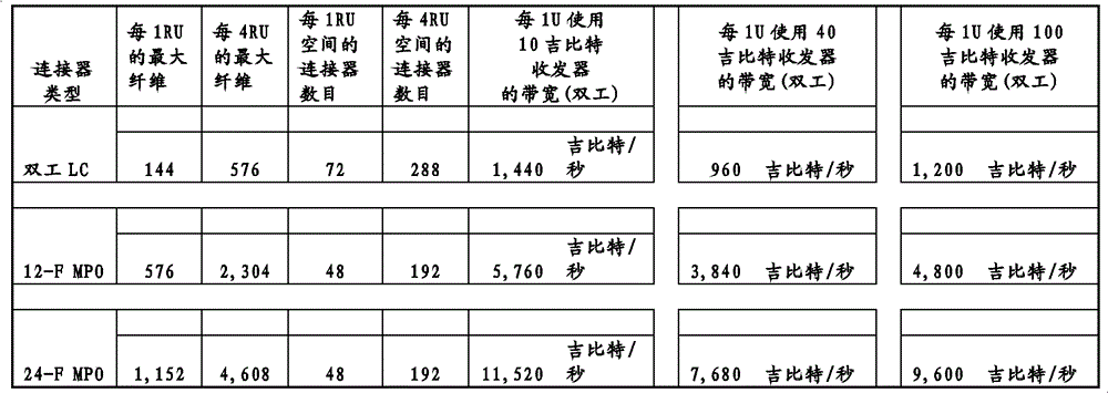
因此,概括而言,下面的表格总结了一些利用上述的各种实施方案的光纤模块、光纤设备托盘和盘架在1-U和4-U空间中能够提供的光纤连接密度和带宽。例如,用于一个(1)发送/接收对的双工的两根(2)光导纤维能够允许在半双工模式每秒十(10)吉比特的数据速率、在全双工模式每秒二十(20)吉比特的数据速率。作为另一个实施例,用于四个(4)发送/接收对的双工的十二(12)纤维MPO光纤连接器中的八根(8)光导纤维能够允许在半双工模式每秒四十(40)吉比特的数据速率、在全双工模式每秒八十(80)吉比特的数据速率。作为另一个实施例,用于十个(10)发送/接收对的双工的二十四(24)纤维MPO光纤连接器中的二十根光导纤维能够允许在半双工模式实现每秒一百(100)吉比特的数据速率、在全双工模式实现每秒二百(200)吉比特的数据速率。注意到,这个表格是示例性的,此处公开的实施方案不限于下面提供的光纤连接密度和带宽。In summary, therefore, the table below summarizes some of the fiber optic connection densities and bandwidths that can be provided in 1-U and 4-U spaces using the fiber optic modules, fiber optic equipment trays, and racks of the various embodiments described above. For example, two (2) optical fibers for duplexing one (1) transmit/receive pair can allow data rates of ten (10) gigabits per second in half-duplex mode, two gigabits per second in full-duplex mode, Ten (20) gigabit data rate. As another example, eight (8) optical fibers in a duplex twelve (12) fiber MPO fiber optic connector for four (4) transmit/receive pairs can allow four (4) per second in half-duplex mode. Ten (40) gigabit data rate, eighty (80) gigabit per second data rate in full duplex mode. As another example, twenty optical fibers in a twenty-four (24) fiber MPO fiber optic connector for duplexing of ten (10) transmit/receive pairs can allow one Data rates of one hundred (100) gigabits, two hundred (200) gigabits per second in full duplex mode. Note that this table is exemplary and the embodiments disclosed herein are not limited to the fiber connection densities and bandwidths provided below.
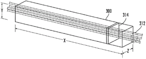
除了提供高光纤连接密度的高密度光纤模块以外,还可实现光纤电缆封装密度。图26示出1-U光纤电缆路由区域300,该区域提供高光纤电缆封装密度。尽管在图26中示出的实施方案中,1-U光纤电缆路由区域300被描述为在1-U盘架的前面,所述1-U盘架具有支承带有LC双工适配器的模块的光纤设备托盘,但应理解,关于1-U光纤电缆路由区域300的讨论适用于具有任意U尺寸、带有任意类型适配器的光纤设备,无论所述光纤设备是否包括在模块中,以及模块的尺寸或类型如何。因此,各种U尺寸的光纤设备将具有与1-U光纤电缆路由区域300相等的数目。In addition to high-density fiber optic modules that provide high fiber optic connection density, fiber optic cable packing density can be achieved. Figure 26 illustrates a 1-U fiber optic
所述1-U光纤电缆路由区域300由宽度、高度、深度尺寸限定。在这一实施方案中,图26中标为“X”的宽度尺寸可以是约16.17英寸。图26中标为“Y”的高度尺寸可以是约1.45英寸。图26中标为“Z”的深度尺寸可以是约3.38英寸。因此,所述1-U光纤电缆路由区域300总体居中位于1-U盘架前面,并且可具有如下计算的体积:The 1-U fiber optic
16.17英寸×1.45英寸×3.38英寸=79.25英寸3 16.17 inches x 1.45 inches x 3.38 inches = 79.25 inches3
位于1-U光纤电缆路由区域300内的光纤电缆310可包括连接至光纤设备上的连接器的一个或多个光纤电缆,所述光纤设备位于该1-U空间中,光纤电缆横穿过该1-U空间用于连接至其他光纤设备。然而,所有这些光纤电缆310都可在1-U光纤电缆路由区域300内以基本水平方向路由。这允许连接至位于该1-U空间中的光纤设备上的连接器的光纤电缆310在路由出1-U光纤电缆路由区域300之前弯曲一次。一旦光纤电缆310离开1-U光纤电缆路由区域300,其将向上或向下竖直弯曲,以路由进入和/或离开光纤设备架14。这样,光纤电缆310在路由出光纤设备架14之前弯曲不超过两次。The
通过使用抗弯曲纤维,可将更多纤维封装进1-U光纤电缆路由区域300,而不超出误码率(BER)和衰减极限。换言之,可允许更紧凑的弯曲,使得连接至连接器的光纤电缆310在1-U空间占据更小的深度或“Z”尺寸。如TIA/EIA-568标准确定的,用于数据传输的可接受的最大BER是10-12,以及可接受的最大衰减是0.75dB。以下在本公开文本中被称为BER极限和衰减极限。By using bend resistant fibers, more fibers can be packed into the 1-U fiber optic
现在参照图27,1-U光纤电缆路由区域300被示为从1-U空间的前部去除。被示意性描述为从光导纤维电缆310中取出的光导纤维312的一个代表示例被示为在1-U光纤电缆路由区域300中路由。所述光导纤维312被示为横穿过一个竖直切割通过1-U光纤电缆路由区域300的增量式截面314。一个或多个光导纤维可被包括在一个或多个光纤电缆310中,所述光纤电缆310连接至在1-U光纤电缆路由区域300的具体的1-U空间中的光纤设备上的连接上。Referring now to FIG. 27, the 1-U fiber optic
在所述连接中的至少一个使用LC单工或双工连接器类型的情况中,至少大约98根光导纤维312可横穿过1-U光纤电缆路由区域300的增量式截面314,而不超过BER极限和/或衰减极限。换言之,每1-U搁板空间可路由至少98根光导纤维312,而不超过BER极限和/或衰减极限。此外,在该情况中,约98根到约144根的光导纤维312可横穿过1-U光纤电缆路由区域300的增量式截面314,而不超过BER极限和/或衰减极限。Where at least one of the connections uses an LC simplex or duplex connector type, at least about 98
在所述连接装置中的至少一个使用12纤维MPO连接器类型的情况中,至少大约434根光导纤维312可横穿过1-U光纤电缆路由区域300的增量式截面314,而不超过BER极限和/或衰减极限。换言之,每1-U搁板空间可路由至少434根光导纤维312,而不超过BER极限和/或衰减极限。此外,在该情况中,约434根到约576根光导纤维312可横穿过1-U光纤电缆路由区域300的增量式截面314,而不超过BER极限和/或衰减极限。Where at least one of the connecting devices uses a 12-fiber MPO connector type, at least about 434
在所述连接装置中的至少一个使用24纤维MPO连接器类型的情况中,至少大约866根光导纤维312可横穿过1-U光纤电缆路由区域300的增量式截面314,而不超过BER极限和/或衰减极限。换言之,每1-U搁板空间可路由至少866根光导纤维312,而不超过BER极限和/或衰减极限。此外,在该情况中,约866根到约1152根光导纤维312可横穿过1-U光纤电缆路由区域300的增量式截面314,而不超过BER极限和/或衰减极限。Where at least one of the connecting devices uses a 24-fiber MPO connector type, at least about 866
此外,不管连接器类型如何,至少约1152根光导纤维312可横穿过1-U光纤电缆路由区域300的增量式截面314,而不超过BER极限和/或衰减极限。换言之,每1-U搁板空间可路由至少1152根光导纤维312,而不超过BER极限和/或衰减极限。Furthermore, regardless of the connector type, at least about 1152
如此处使用的,术语“光纤电缆”和/或“光导纤维”包括所有类型的单模和多模光波导,包括一种或多种可以是无涂层的、有色的、缓冲的、带状的,和/或在电缆中具有其他有组织的或保护性的结构,诸如一种或多种管、强度构件、护套等等。同样地,其他合适类型的光导纤维包括抗弯曲光导纤维、或任何其他有利于传输光信号的介质。抗弯曲光导纤维的一个实施例是可从Corning Incorporated公司商购得到的多模纤维。As used herein, the terms "fiber optic cable" and/or "optical fiber" include all types of single-mode and multimode optical waveguides, including one or more types that may be uncoated, colored, buffered, ribbon and/or have other organizing or protective structures in the cable, such as one or more tubes, strength members, sheathing, etc. Likewise, other suitable types of optical fibers include bend-resistant optical fibers, or any other medium that facilitates the transmission of optical signals. One example of a bend resistant optical fiber is commercially available from Corning Incorporated multimode fiber.
应理解,本公开文本不限于所公开的具体实施方案,修改和其他实施方案意在包括在所附权利要求的范围内。尽管此处使用了具体的术语,但它们仅以总的描述性含义使用,而不意在限制。It is to be understood that the disclosure is not to be limited to the particular embodiments disclosed and that modifications and other embodiments are intended to be included within the scope of the appended claims. Although specific terms are used herein, they are used in a general descriptive sense only and are not intended to be limiting.
Claims (20)
Applications Claiming Priority (3)
| Application Number | Priority Date | Filing Date | Title |
|---|---|---|---|
| US21887809P | 2009-06-19 | 2009-06-19 | |
| US61/218,878 | 2009-06-19 | ||
| PCT/US2010/039210 WO2010148325A1 (en) | 2009-06-19 | 2010-06-18 | High fiber optic cable packing density apparatus |
Publications (1)
| Publication Number | Publication Date |
|---|---|
| CN102804014A true CN102804014A (en) | 2012-11-28 |
Family
ID=42732804
Family Applications (1)
| Application Number | Title | Priority Date | Filing Date |
|---|---|---|---|
| CN2010800348306A Pending CN102804014A (en) | 2009-06-19 | 2010-06-18 | High fiber optic cable packing density apparatus |
Country Status (7)
| Country | Link |
|---|---|
| US (1) | US8433171B2 (en) |
| EP (1) | EP2443498B1 (en) |
| JP (1) | JP2012530943A (en) |
| CN (1) | CN102804014A (en) |
| AU (1) | AU2010263046B2 (en) |
| CA (1) | CA2765830A1 (en) |
| WO (1) | WO2010148325A1 (en) |
Cited By (1)
| Publication number | Priority date | Publication date | Assignee | Title |
|---|---|---|---|---|
| CN117849967A (en) * | 2022-10-07 | 2024-04-09 | 罗森伯格Osi股份有限公司 | Modular assemblies, carrier units and carrier devices for the fiber optic distribution industry |
Families Citing this family (59)
| Publication number | Priority date | Publication date | Assignee | Title |
|---|---|---|---|---|
| US11294136B2 (en) | 2008-08-29 | 2022-04-05 | Corning Optical Communications LLC | High density and bandwidth fiber optic apparatuses and related equipment and methods |
| US8452148B2 (en) | 2008-08-29 | 2013-05-28 | Corning Cable Systems Llc | Independently translatable modules and fiber optic equipment trays in fiber optic equipment |
| US20100322583A1 (en) | 2009-06-19 | 2010-12-23 | Cooke Terry L | High Density and Bandwidth Fiber Optic Apparatuses and Related Equipment and Methods |
| US9075216B2 (en) | 2009-05-21 | 2015-07-07 | Corning Cable Systems Llc | Fiber optic housings configured to accommodate fiber optic modules/cassettes and fiber optic panels, and related components and methods |
| US8593828B2 (en) | 2010-02-04 | 2013-11-26 | Corning Cable Systems Llc | Communications equipment housings, assemblies, and related alignment features and methods |
| US8913866B2 (en) | 2010-03-26 | 2014-12-16 | Corning Cable Systems Llc | Movable adapter panel |
| CN102884469B (en) | 2010-04-16 | 2016-09-28 | Ccs技术股份有限公司 | Sealing and strain relief means for data cable |
| US8879881B2 (en) | 2010-04-30 | 2014-11-04 | Corning Cable Systems Llc | Rotatable routing guide and assembly |
| US9075217B2 (en) | 2010-04-30 | 2015-07-07 | Corning Cable Systems Llc | Apparatuses and related components and methods for expanding capacity of fiber optic housings |
| US9519118B2 (en) | 2010-04-30 | 2016-12-13 | Corning Optical Communications LLC | Removable fiber management sections for fiber optic housings, and related components and methods |
| WO2011143537A1 (en) | 2010-05-14 | 2011-11-17 | Afl Telecommunications Llc | Fiber optic cable management module and panel |
| US9279951B2 (en) | 2010-10-27 | 2016-03-08 | Corning Cable Systems Llc | Fiber optic module for limited space applications having a partially sealed module sub-assembly |
| EP2646867B1 (en) | 2010-11-30 | 2018-02-21 | Corning Optical Communications LLC | Fiber device holder and strain relief device |
| WO2012106518A2 (en) | 2011-02-02 | 2012-08-09 | Corning Cable Systems Llc | Optical backplane extension modules, and related assemblies suitable for establishing optical connections to information processing modules disposed in equipment racks |
| US8556356B2 (en) | 2011-02-21 | 2013-10-15 | Commscope, Inc. Of North Carolina | Communication shelf having supports for pivotable adapter panels and method of mounting adapter panels therein |
| US9008485B2 (en) | 2011-05-09 | 2015-04-14 | Corning Cable Systems Llc | Attachment mechanisms employed to attach a rear housing section to a fiber optic housing, and related assemblies and methods |
| US8989547B2 (en) | 2011-06-30 | 2015-03-24 | Corning Cable Systems Llc | Fiber optic equipment assemblies employing non-U-width-sized housings and related methods |
| US8953924B2 (en) | 2011-09-02 | 2015-02-10 | Corning Cable Systems Llc | Removable strain relief brackets for securing fiber optic cables and/or optical fibers to fiber optic equipment, and related assemblies and methods |
| CN103975264B (en) | 2011-10-07 | 2015-09-16 | Adc电信公司 | Slidable fiber optic connection module with cable slack management |
| US9038832B2 (en) | 2011-11-30 | 2015-05-26 | Corning Cable Systems Llc | Adapter panel support assembly |
| US20130308916A1 (en) * | 2012-05-16 | 2013-11-21 | Scott Eaker Buff | High-density port tap fiber optic modules, and related systems and methods for monitoring optical networks |
| US9420715B2 (en) * | 2012-06-07 | 2016-08-16 | Intal Tech Ltd. | Electrononic equipment building blocks for rack mounting |
| US9250409B2 (en) | 2012-07-02 | 2016-02-02 | Corning Cable Systems Llc | Fiber-optic-module trays and drawers for fiber-optic equipment |
| US20140010510A1 (en) * | 2012-07-03 | 2014-01-09 | Stephen R. Blackard | Optical fiber connectivity management system |
| US9042702B2 (en) | 2012-09-18 | 2015-05-26 | Corning Cable Systems Llc | Platforms and systems for fiber optic cable attachment |
| US10082636B2 (en) | 2012-09-21 | 2018-09-25 | Commscope Technologies Llc | Slidable fiber optic connection module with cable slack management |
| ES2551077T3 (en) | 2012-10-26 | 2015-11-16 | Ccs Technology, Inc. | Fiber optic management unit and fiber optic distribution device |
| US9128262B2 (en) | 2013-02-05 | 2015-09-08 | Adc Telecommunications, Inc. | Slidable telecommunications tray with cable slack management |
| US20140247541A1 (en) * | 2013-02-26 | 2014-09-04 | Realm Communications Group, Inc. | Telecom cabinet dual tray slider |
| US8985862B2 (en) | 2013-02-28 | 2015-03-24 | Corning Cable Systems Llc | High-density multi-fiber adapter housings |
| CN105164560B (en) * | 2013-03-05 | 2017-03-22 | 菲尼萨公司 | Latch mechanism for communication module |
| US9494758B2 (en) | 2014-04-03 | 2016-11-15 | Commscope Technologies Llc | Fiber optic distribution system |
| US9690065B2 (en) | 2014-09-12 | 2017-06-27 | Panduit Corp. | High density fiber enclosure and method |
| US9921383B2 (en) * | 2014-09-24 | 2018-03-20 | Champion Optical Network Engineering, Llc | High-density modular WDM system—high density passive fiber module (PFM), tray and chassis interchangeable solution |
| US9885845B2 (en) * | 2015-01-15 | 2018-02-06 | Commscope, Inc. Of North Carolina | Module and assembly for fiber optic interconnections |
| US9257788B1 (en) * | 2015-01-23 | 2016-02-09 | Oracle International Corporation | Connector retention and alignment assembly for use in computer and data storage mounting racks |
| DE102015118338A1 (en) * | 2015-10-27 | 2017-04-27 | Reichle & De-Massari Ag | Patch panel device and modular system for producing a patch panel device |
| JP6438426B2 (en) * | 2016-03-30 | 2018-12-12 | Seiオプティフロンティア株式会社 | Optical switching unit and optical switching device |
| WO2017184508A1 (en) | 2016-04-19 | 2017-10-26 | Commscope, Inc. Of North Carolina | Telecommunications chassis with slidable trays |
| WO2017184501A1 (en) | 2016-04-19 | 2017-10-26 | Commscope, Inc. Of North Carolina | Door assembly for a telecommunications chassis with a combination hinge structure |
| JP6741929B2 (en) | 2016-06-09 | 2020-08-19 | 住友電工オプティフロンティア株式会社 | Multi-core single-core conversion module and multi-core single-core conversion device |
| US10215944B2 (en) | 2016-06-30 | 2019-02-26 | Panduit Corp. | Modular fiber optic tray |
| USD820234S1 (en) * | 2016-07-11 | 2018-06-12 | Leader Optec Limited | Telecommunications apparatus |
| CN110462478B (en) | 2017-04-04 | 2021-05-07 | 康普技术有限责任公司 | Optical connector and termination module |
| US10670822B2 (en) | 2017-06-28 | 2020-06-02 | Afl Telecommunications Llc | High density patch panel with modular cassettes |
| CA3221718C (en) | 2017-10-03 | 2024-06-18 | Belden Canada Ulc | Modular fiber optic cassette, system and method |
| US11385429B2 (en) | 2017-10-18 | 2022-07-12 | Commscope Technologies Llc | Fiber optic connection cassette |
| EP3759535A4 (en) | 2018-02-28 | 2021-11-10 | CommScope Technologies LLC | HOUSING ARRANGEMENT FOR TELECOMMUNICATION EQUIPMENT |
| WO2019204317A1 (en) | 2018-04-16 | 2019-10-24 | Commscope Technologies Llc | Adapter structure |
| US10969554B2 (en) | 2019-04-01 | 2021-04-06 | Afl Telecommunications Llc | Fiber optic tray systems |
| US11237348B2 (en) | 2019-04-17 | 2022-02-01 | Afl Ig Llc | Patch panel with lifting cassette removal |
| TWM602773U (en) * | 2020-03-03 | 2020-10-11 | 光紅建聖股份有限公司 | Primary-secondary type hub chassis |
| CN113885138A (en) | 2020-07-01 | 2022-01-04 | 罗森伯格高频技术有限及两合公司 | Fiber Optic Modules, Fiber Optic Module Kits, and Optical Distribution Frames |
| DE102020126734B4 (en) | 2020-10-12 | 2024-06-13 | Zellner Gmbh | System insert with swiveling connector coupling piece |
| WO2022178317A1 (en) | 2021-02-18 | 2022-08-25 | Commscope Technologies Llc | Communications panel system |
| US11971598B2 (en) | 2021-02-18 | 2024-04-30 | Commscope Technologies Llc | Tray arrangements for cassettes |
| US12523835B2 (en) * | 2021-04-23 | 2026-01-13 | Fujikura Ltd. | Optical termination box |
| CA3223794A1 (en) * | 2022-12-19 | 2024-06-19 | The Lan Wirewerks Research Laboratories Inc. | Module comprising drop-in adapters |
| EP4498141B1 (en) * | 2023-07-28 | 2025-11-26 | Rosenberger-OSI GmbH & Co. OHG | Rail assembly, beam assembly and fiber optic distribution system |
Citations (2)
| Publication number | Priority date | Publication date | Assignee | Title |
|---|---|---|---|---|
| US20050135768A1 (en) * | 2003-12-23 | 2005-06-23 | Rapp David E. | High density optical fiber distribution frame with modules |
| US20090067800A1 (en) * | 2007-09-07 | 2009-03-12 | Mariano Perez Vazquez | Fiber optic adapter module and tray |
Family Cites Families (639)
| Publication number | Priority date | Publication date | Assignee | Title |
|---|---|---|---|---|
| US620013A (en) * | 1899-02-21 | Medicine-case | ||
| US3175873A (en) * | 1961-06-09 | 1965-03-30 | Fmc Corp | Panel locking mechanism for console type structures |
| US3906592A (en) * | 1974-04-25 | 1975-09-23 | Nissan Motor | Wiring or piping clamp |
| US4059872A (en) * | 1975-11-24 | 1977-11-29 | Domenico Delesandri | Hose clamp assembly |
| JPS5392490A (en) | 1977-01-21 | 1978-08-14 | Bunker Ramo | Connecting terminal module and method of producing same |
| US4285486A (en) * | 1979-07-12 | 1981-08-25 | Jewell Von Osten | Cord holder |
| US4354731A (en) * | 1979-10-02 | 1982-10-19 | E. I. Du Pont De Nemours And Company | Self-aligning optical fiber connector |
| DE3328052A1 (en) * | 1983-08-03 | 1985-02-21 | Siemens AG, 1000 Berlin und 8000 München | MOUNTING DEVICE FOR MULTIPLE CONNECTORS FOR LIGHTWAVE GUIDES |
| US5602954A (en) | 1984-04-11 | 1997-02-11 | Raychem Sv | Electrofit fiber optics butt splice |
| US5157749A (en) * | 1984-06-08 | 1992-10-20 | Amp Incorporated | High precision optical fiber connectors |
| US4597173A (en) * | 1984-06-20 | 1986-07-01 | The United States Of America As Represented By The Secretary Of The Navy | Electronic module insertion and retraction mechanism |
| US4611875A (en) * | 1984-08-23 | 1986-09-16 | At&T Information Systems | Communication system cross-connect field power adapter |
| US4702551A (en) * | 1984-10-11 | 1987-10-27 | Reliance Comm/Tec Corporation | Method and apparatus for handling and storing cabled spliced ends of fiber optics |
| DE3687869T2 (en) * | 1985-07-26 | 1993-06-17 | Matsushita Electric Ind Co Ltd | HOLOGRAPHICAL MULTIPLEX / DEMULTIPLEX DEVICE, AND THEIR PRODUCTION METHOD. |
| DE3532313A1 (en) * | 1985-09-11 | 1987-03-12 | Philips Patentverwaltung | STORAGE CONTAINER FOR A LENGTH SECTION OF A FOCUS |
| US4792203A (en) * | 1985-09-17 | 1988-12-20 | Adc Telecommunications, Inc. | Optical fiber distribution apparatus |
| FR2590371B1 (en) * | 1985-11-18 | 1988-09-16 | Cit Alcatel | OPTICAL CABLES HEAD CHASSIS |
| US4831403A (en) * | 1985-12-27 | 1989-05-16 | Minolta Camera Kabushiki Kaisha | Automatic focus detection system |
| DE3726719A1 (en) | 1986-04-07 | 1989-02-23 | Siemens Ag | DEVICE FOR ATTACHING A MECHANICAL CONNECTION TO THE CABLE SHEATH OF AN OPTICAL CABLE |
| DE3726718A1 (en) | 1986-04-07 | 1989-02-23 | Siemens Ag | DEVICE FOR ATTACHING A MECHANICAL CONNECTION TO THE CABLE SHEATH OF AN OPTICAL CABLE |
| US4747020A (en) * | 1986-05-16 | 1988-05-24 | Adc Telecommunications, Inc. | Wire distribution apparatus |
| EP0250900A3 (en) | 1986-06-25 | 1989-07-19 | Siemens Aktiengesellschaft | Distributor for telecommunication arrangements with light wave guides |
| US4736100A (en) * | 1986-07-31 | 1988-04-05 | Amp Incorporated | Optical loop attenuator simulating an optical system |
| US4824196A (en) * | 1987-05-26 | 1989-04-25 | Minnesota Mining And Manufacturing Company | Optical fiber distribution panel |
| DE8711970U1 (en) | 1987-09-04 | 1987-10-15 | kabelmetal electro GmbH, 3000 Hannover | Cable termination device for optical fibers |
| US5017211A (en) * | 1987-09-23 | 1991-05-21 | Ciba-Geigy Corporation | Heterocyclic compounds |
| US4808774A (en) * | 1987-10-19 | 1989-02-28 | Gte Products Corporation | Strain relief device |
| US4826277A (en) * | 1987-10-30 | 1989-05-02 | Amp Incorporated | Transition of a multiple fiber cable to single fiber cable |
| GB8729952D0 (en) * | 1987-12-23 | 1988-02-03 | British Telecomm | Mounting assembly for optical equipment |
| US4838643A (en) * | 1988-03-23 | 1989-06-13 | Alcatel Na, Inc. | Single mode bend insensitive fiber for use in fiber optic guidance applications |
| US4898448A (en) * | 1988-05-02 | 1990-02-06 | Gte Products Corporation | Fiber distribution panel |
| FR2633061B1 (en) * | 1988-06-20 | 1992-02-14 | Telecommunications Sa | BREWING, DISTRIBUTION AND / OR CONNECTION MODULE FOR OPTICAL FIBERS AND ITS APPLICATIONS |
| US4900123A (en) * | 1988-08-29 | 1990-02-13 | Gte Products Corporation | 1550 nm fiber distribution panel |
| US5028114A (en) * | 1988-09-29 | 1991-07-02 | Siemens Aktiengesellschaft | Plug connector for fiber optic cables |
| DE3838428A1 (en) * | 1988-11-12 | 1990-05-31 | Philips Patentverwaltung | SWITCH DISTRIBUTOR FOR THE PRODUCTION OF FREELY SELECTABLE OPTICAL CONNECTORS |
| US4865280A (en) * | 1988-11-25 | 1989-09-12 | Phillips Plastics Corporation | One-piece wire retainer clip with expandable fastener for securing elongated members to a structure |
| US5001602A (en) * | 1988-11-28 | 1991-03-19 | Reliance Comm/Tec Corporation | Network interface cabinet for large pair count telephone terminations |
| US5071211A (en) * | 1988-12-20 | 1991-12-10 | Northern Telecom Limited | Connector holders and distribution frame and connector holder assemblies for optical cable |
| US4911662A (en) * | 1988-12-20 | 1990-03-27 | Northern Telecom Limited | Distribution frame for telecommunications cable |
| US5152760A (en) * | 1989-03-17 | 1992-10-06 | The General Hospital Corporation | Non-invasive sclerostomy |
| FR2646928B1 (en) * | 1989-05-11 | 1993-12-24 | Etat Francais Cnet | MODULE AND CONNECTION BOX FOR FIBER OPTIC CABLES |
| US4949376A (en) * | 1989-06-15 | 1990-08-14 | Keptel, Inc. | Telephone network interface apparatus |
| GB8915846D0 (en) | 1989-07-11 | 1989-08-31 | Bicc Plc | Termination system for optical fibres |
| US4995688A (en) | 1989-07-31 | 1991-02-26 | Adc Telecommunications, Inc. | Optical fiber distribution frame |
| US5005941A (en) * | 1989-09-05 | 1991-04-09 | Gte Products Corporation | Fiber optic splice assembly |
| WO1991005281A1 (en) | 1989-09-29 | 1991-04-18 | Northern Telecom Limited | Connector holders and distribution frame and connector holder assemblies for optical cable |
| US4971421A (en) * | 1989-09-29 | 1990-11-20 | Reliance Comm/Tec Corporation | Fiber optic splice and patch enclosure |
| JP2771870B2 (en) | 1989-12-01 | 1998-07-02 | 日本電信電話株式会社 | Optical connector |
| US5100221A (en) * | 1990-01-22 | 1992-03-31 | Porta Systems Corp. | Optical fiber cable distribution frame and support |
| US5048918A (en) * | 1990-02-07 | 1991-09-17 | Raychem Corporation | Optical fiber cable termination |
| US4991928A (en) * | 1990-02-20 | 1991-02-12 | Siecor Corporation | Movable clamp for fiber optic enclosures |
| GB2241591A (en) | 1990-02-28 | 1991-09-04 | Optical Data Communications Li | Mounting frames for fibre optic or electrical cable organiser trays |
| US5142607A (en) * | 1990-03-20 | 1992-08-25 | Rittal-Werk Rudolf Loh Gmbh & Co. Kg | Splice box for optical wave guide |
| US5076688A (en) * | 1990-03-23 | 1991-12-31 | Amp Incorporated | Optical simulator with loop-back attenuator having metalized optical fiber |
| JPH03279474A (en) | 1990-03-28 | 1991-12-10 | Achilles Corp | Sheet-like material having leather-type appearance |
| US5150277A (en) * | 1990-05-04 | 1992-09-22 | At&T Bell Laboratories | Cooling of electronic equipment cabinets |
| US5153910A (en) * | 1990-05-15 | 1992-10-06 | Gte Products Corporation | Protected telephone network interface device |
| US5479505A (en) | 1990-05-15 | 1995-12-26 | Siecor Puerto Rico, Inc. | Telephone network enclosure containing protected termination device |
| US5548641A (en) | 1990-05-15 | 1996-08-20 | Siecor Puerto Rico, Inc. | Protected telephone network termination module |
| US5333193A (en) * | 1990-05-15 | 1994-07-26 | Siecor Puerto Rico, Inc. | Telephone network termination module having insulation displacement terminals |
| US5497416A (en) | 1990-05-15 | 1996-03-05 | Siecor Corporation | Telephone interface security lock |
| US5416837A (en) | 1990-05-15 | 1995-05-16 | Siecor Puerto Rico, Inc. | Telephone network interface enclosure |
| JP2532065Y2 (en) | 1990-05-21 | 1997-04-09 | ミネソタ・マイニング・アンド・マニュファクチュアリング・カンパニー | Optical fiber distribution center |
| US5074635A (en) * | 1990-05-21 | 1991-12-24 | Minnesota Mining And Manufacturing Company | Splice tray and method |
| NO912129L (en) * | 1990-06-04 | 1991-12-05 | Bicc Plc | TERMINATION SYSTEM FOR OPTICAL FIBERS |
| US5037175A (en) * | 1990-06-11 | 1991-08-06 | Amp Incorporated | Clip for dressing of fiber optic cable within confined space |
| US5073042A (en) * | 1990-06-21 | 1991-12-17 | Amp Incorporated | Coupling bushing for various types of optical fiber connectors |
| DE69116019T2 (en) | 1990-07-27 | 1996-08-22 | Whitaker Corp | Glass fiber connector for wall penetration |
| DE59108325D1 (en) | 1990-09-03 | 1996-12-12 | Reichle & De Massari Fa | End closure arrangement for signal transmission cables, in particular glass fiber cables |
| US5066149A (en) * | 1990-09-11 | 1991-11-19 | Adc Telecommunications, Inc. | Splice tray with slack take-up |
| DE4030301A1 (en) | 1990-09-25 | 1992-03-26 | Siemens Ag | DISTRIBUTION DEVICE FOR LIGHTWAVE GUIDE |
| US5133039A (en) * | 1990-10-29 | 1992-07-21 | At&T Bell Laboratories | Aerial fiber optic cable case |
| CA2029592C (en) | 1990-11-08 | 1998-03-31 | George Debortoli | Optical connector holder assembly |
| US5138688A (en) * | 1990-11-09 | 1992-08-11 | Northern Telecom Limited | Optical connector holder assembly |
| US5067784A (en) * | 1990-11-19 | 1991-11-26 | George Debortoli | Connector holders |
| US5222168A (en) | 1990-12-13 | 1993-06-22 | The Furukawa Electric Co., Ltd. | Method for stacking ferrules of a stacked-type optical connector and a stacked-type optical connector |
| US5127082A (en) * | 1991-03-22 | 1992-06-30 | The Siemon Company | Fiber optic patch panel |
| US5125060A (en) * | 1991-04-05 | 1992-06-23 | Alcatel Na Cable Systems, Inc. | Fiber optic cable having spliceless fiber branch and method of making |
| JP2538394Y2 (en) * | 1991-05-29 | 1997-06-11 | 住友電気工業株式会社 | Optical connector |
| JPH04350801A (en) | 1991-05-29 | 1992-12-04 | Furukawa Electric Co Ltd:The | Branch part of multi-unit coated optical fiber |
| USD330368S (en) * | 1991-05-30 | 1992-10-20 | Northern Telecom Limited | Tray for housing splices and excess lengths of optical fibers |
| US5129030A (en) * | 1991-05-30 | 1992-07-07 | At&T Bell Laboratories | Movable lightguide connector panel |
| JP3160322B2 (en) | 1991-08-14 | 2001-04-25 | 日本電信電話株式会社 | Optical connector structure |
| US5142598A (en) * | 1991-08-28 | 1992-08-25 | Porta Systems Corp. | Fiber optic connector having snap ring adjustment means |
| CA2050356C (en) | 1991-08-30 | 2003-02-11 | George Debortoli | Optical fiber storage |
| US5167001A (en) * | 1991-09-03 | 1992-11-24 | Northern Telecom Limited | Optical fiber storage and connector tray and shelf and tray assembly |
| US5204929A (en) * | 1991-09-04 | 1993-04-20 | Reliance Comm/Tec Corporation | Fiber patch panel |
| US5231688A (en) * | 1991-10-07 | 1993-07-27 | Siecor Corporation | Furcation kit |
| US5209572A (en) * | 1991-11-08 | 1993-05-11 | Accuride International, Inc. | Thin drawer slide |
| US5233674A (en) * | 1991-11-21 | 1993-08-03 | Methode Electronics, Inc. | Fiber optic connector with sliding tab release |
| JPH05150120A (en) * | 1991-11-29 | 1993-06-18 | Fujitsu Ltd | Lead-in structure for optical fiber cable |
| US5210810A (en) | 1991-12-19 | 1993-05-11 | At&T Bell Laboratories | Hermaphroditic connector for single fiber optical cable |
| FR2685851B1 (en) | 1991-12-30 | 1994-02-04 | Alcatel Cit | DEVICE FOR SUPPORTING AND GUIDING CABLES FOR TRANSMITTING ELECTRIC OR LIGHT SIGNALS. |
| US5243679A (en) * | 1992-02-07 | 1993-09-07 | Gv Medical, Inc. | Optical fiber advancement, retraction and storage system |
| FR2687743B1 (en) * | 1992-02-21 | 1995-06-16 | Mars Actel | SET OF STACKED AND ARTICULATED MODULES. |
| FR2687744B1 (en) * | 1992-02-21 | 1994-04-08 | Mars Actel | SET OF ARTICULATED FLAT MODULES. |
| FR2687800B1 (en) * | 1992-02-21 | 1994-04-08 | Mars Actel | ADAPTABLE CASSETTE FOR LOVING AND SPLICING OPTICAL FIBERS. |
| US5239609A (en) * | 1992-03-03 | 1993-08-24 | Porta Systems Corp. | Means for routing buffer tube type fiber optical cable |
| US5280138A (en) * | 1992-03-31 | 1994-01-18 | Virginia Plastics Company, Inc. | Cable protector |
| US5214735A (en) * | 1992-04-06 | 1993-05-25 | Adc Telecommunications, Inc. | Fiber optic connector retainer |
| GB9212624D0 (en) | 1992-06-15 | 1992-07-29 | Raychem Sa Nv | Cable sealing device |
| US5333221A (en) * | 1992-06-30 | 1994-07-26 | The Whitaker Corporation | Universal adapter for optical connectors |
| US5274729A (en) | 1992-07-30 | 1993-12-28 | At&T Bell Laboratories | Universal optical fiber buildout system |
| DE4231181C1 (en) | 1992-09-17 | 1993-08-26 | Siemens Ag, 8000 Muenchen, De | Cable restraint for fibre=optic cable distribution box - comprises U=shaped fixing shell fastened to rail which mounts screw for fixing cable central strain element |
| CA2081608C (en) * | 1992-10-28 | 1998-05-05 | Joseph Octave Regis Morin | Distribution frame and optical connector holder combination |
| US5260957A (en) * | 1992-10-29 | 1993-11-09 | The Charles Stark Draper Laboratory, Inc. | Quantum dot Laser |
| US5383051A (en) * | 1992-10-30 | 1995-01-17 | Pirelli Cavi S.P.A. | Compact-size optical amplifier |
| US5323480A (en) * | 1992-11-25 | 1994-06-21 | Raychem Corporation | Fiber optic splice closure |
| US5261633A (en) * | 1992-12-17 | 1993-11-16 | Mastro Ronald J | Pipe support system |
| US5274731A (en) * | 1992-12-24 | 1993-12-28 | Adc Telecommunications, Inc. | Optical fiber cabinet |
| DE4302837A1 (en) | 1993-01-28 | 1994-08-18 | Krone Ag | Housing for passive optical components |
| US5401193A (en) | 1993-02-10 | 1995-03-28 | Lo Cicero; Rae-Ann | Patch panel system |
| US5436994A (en) | 1993-02-26 | 1995-07-25 | Ott; Conrad L. | Ferrule holder for fiber optic connector |
| US5399814A (en) | 1993-03-15 | 1995-03-21 | Siecor Corporation | Cable bend control device |
| FR2703160B1 (en) | 1993-03-26 | 1995-06-02 | Corning Inc | Cassette for optical fiber device, fitted with a bundle of flexible fiber protection tubes. |
| GB9306854D0 (en) | 1993-04-01 | 1993-05-26 | Raychem Sa Nv | Optical fibre organizer |
| GB9307488D0 (en) | 1993-04-08 | 1993-06-02 | Amp Holland | Optical fibre connector latching mechanism |
| US5546495A (en) | 1993-04-16 | 1996-08-13 | The Whitaker Corporation | Splice tray rack and cabinet for fiber optic cables |
| US5333222A (en) * | 1993-05-14 | 1994-07-26 | Molex Incorporated | Adapter for interconnecting optical fiber connectors or the like |
| US5317663A (en) * | 1993-05-20 | 1994-05-31 | Adc Telecommunications, Inc. | One-piece SC adapter |
| US5443232A (en) | 1993-05-24 | 1995-08-22 | Kesinger; Donald A. | Apparatus for hanging TV cable and the like |
| US5373421A (en) * | 1993-06-02 | 1994-12-13 | Digital Equipment Corporation | Fiber optic transceiver mounting bracket |
| US5347603A (en) * | 1993-06-14 | 1994-09-13 | Molex Incorporated | Right angle cable strain relief |
| US5339379A (en) * | 1993-06-18 | 1994-08-16 | Telect, Inc. | Telecommunication fiber optic cable distribution apparatus |
| JP2524471B2 (en) | 1993-07-22 | 1996-08-14 | 日本電気株式会社 | EMI gasket |
| US5414765A (en) | 1993-08-23 | 1995-05-09 | Siecor Corporation | Network interface device having switch |
| US5442725A (en) | 1993-08-30 | 1995-08-15 | At&T Corp. | Pivotally mounted tray for organizing optical fibers |
| US5412751A (en) | 1993-08-31 | 1995-05-02 | The Siemon Company | Retrofittable multimedia patch management system |
| US5398295A (en) * | 1993-09-08 | 1995-03-14 | Chang; Peter C. | Duplex clip for optical fiber connector assembly |
| US5367598A (en) * | 1993-10-21 | 1994-11-22 | Nec America, Inc. | Interface chassis for fiber optic transport system |
| US5353367A (en) * | 1993-11-29 | 1994-10-04 | Northern Telecom Limited | Distribution frame and optical connector holder combination |
| DE4341576A1 (en) | 1993-12-07 | 1995-06-08 | Hoechst Ag | Process for the preparation of alkoxylates using ester compounds as a catalyst |
| US5490229A (en) | 1993-12-08 | 1996-02-06 | At&T Ipm Corp. | Slidably mounted optical fiber distribution tray |
| US5481939A (en) | 1993-12-28 | 1996-01-09 | Litton Systems, Inc. | Cable strain relief device |
| TW232757B (en) | 1994-01-21 | 1994-10-21 | Adc Telecommunications Inc | High-density fiber distribution frame |
| US5442726A (en) | 1994-02-22 | 1995-08-15 | Hubbell Incorporated | Optical fiber storage system |
| US5402515A (en) | 1994-03-01 | 1995-03-28 | Minnesota Mining And Manufacturing Company | Fiber distribution frame system, cabinets, trays and fiber optic connector couplings |
| US5359688A (en) * | 1994-03-04 | 1994-10-25 | Siecor Corporation | Metal internal holding clips for fiber optic connector coupling |
| US5408557A (en) | 1994-04-20 | 1995-04-18 | Hsu; Chung-Tang | FC-type optical fiber cable connector's adaptor |
| DE4415218C1 (en) | 1994-04-26 | 1995-10-19 | Krone Ag | Housing for optical components |
| US5458019A (en) | 1994-04-26 | 1995-10-17 | Siecor Corporation | Fiber optic cable retaining guide |
| US5511144A (en) | 1994-06-13 | 1996-04-23 | Siecor Corporation | Optical distribution frame |
| US5608606A (en) | 1994-06-14 | 1997-03-04 | Apple Computer, Inc. | Computer plug-in module and interconnection system for wireless applications |
| JP2762930B2 (en) | 1994-06-14 | 1998-06-11 | 日本電気株式会社 | Thin inner and outer circumference access optical head |
| US5519804A (en) | 1994-06-22 | 1996-05-21 | At&T Corp. | Universal splice tray |
| US5481634A (en) | 1994-06-24 | 1996-01-02 | At&T Corp. | Connector for optical fiber |
| EP0693699B1 (en) | 1994-07-21 | 1999-12-01 | RXS Kabelgarnituren Gesellschaft mit beschränkter Haftung | Anchoring device for optical cables |
| WO1996010203A1 (en) | 1994-09-28 | 1996-04-04 | Telephone Cables Limited | A splice tray |
| US5881200A (en) | 1994-09-29 | 1999-03-09 | British Telecommunications Public Limited Company | Optical fibre with quantum dots |
| US5450518A (en) | 1994-10-13 | 1995-09-12 | At&T Corp. | Optical fiber cable splice closure |
| US5471555A (en) | 1994-11-21 | 1995-11-28 | Sumitomo Electric Lightwave Corp. | Fiber optic ribbon break-out device with enhanced strain relief |
| US6188687B1 (en) | 1994-11-30 | 2001-02-13 | Verizon Laboratories Inc. | Broadband switch that manages traffic and method therefor |
| FR2728079B1 (en) | 1994-12-08 | 1997-01-10 | Alcatel Cable Interface | DEVICE FOR MAINTAINING AT LEAST ONE OPTICAL FIBER CABLE AND SPLICING BOX BY APPLYING IT |
| ES2109148B1 (en) | 1994-12-30 | 1998-07-01 | Alcatel Standard Electrica | OPTICAL COMMUNICATION NETWORK. |
| US5689605A (en) | 1995-02-09 | 1997-11-18 | Lucent Technologies Inc. | Splice holder assembly for an optical fiber cable splice closure |
| US5575680A (en) | 1995-02-14 | 1996-11-19 | Reliance Com/Tec Corporation | Insulation displacement connector and block |
| JP3212063B2 (en) | 1995-03-08 | 2001-09-25 | 日本電信電話株式会社 | Optical receptacle |
| JP3516765B2 (en) | 1995-03-08 | 2004-04-05 | 株式会社フジクラ | Optical distribution frame |
| JP3173962B2 (en) | 1995-03-13 | 2001-06-04 | 株式会社フジクラ | Optical distribution frame |
| JP3487946B2 (en) | 1995-03-15 | 2004-01-19 | 株式会社フジクラ | Optical distribution frame |
| US5825961A (en) | 1995-03-20 | 1998-10-20 | Psi Telecommunications, Inc. | Fiber optic closure with cable adapter spool |
| US5568584A (en) | 1995-03-20 | 1996-10-22 | Psi Telecommunications, Inc. | Fiber optic closure with cable adapter spool |
| TW286371B (en) | 1995-03-31 | 1996-09-21 | Minnesota Mining & Mfg | |
| US5617501A (en) | 1995-03-31 | 1997-04-01 | Minnesota Mining And Manufacturing Company | Shield bond strain connector for fiber optic closure |
| US5590234A (en) | 1995-03-31 | 1996-12-31 | Minnesota Mining And Manufacturing Company | Fiber optic splice organizers |
| NZ303594A (en) | 1995-03-31 | 1999-01-28 | Minnesota Mining & Mfg | Optical fibre splice tray arrangement |
| US5553183A (en) | 1995-04-03 | 1996-09-03 | Antec Corp. | Apparatus for and methods of splitting fiber optic signals |
| US5631993A (en) | 1995-04-20 | 1997-05-20 | Preformed Line Products Company | Optical fiber splice case |
| US5613030A (en) | 1995-05-15 | 1997-03-18 | The Whitaker Corporation | High density fiber optic interconnection enclosure |
| US5595507A (en) | 1995-05-17 | 1997-01-21 | Lucent Technologies Inc. | Mounting bracket and ground bar for a connector block |
| US5640476A (en) | 1995-07-14 | 1997-06-17 | Siecor Corporation | Guide sleeve for fiber optic cable |
| TW358552U (en) | 1995-08-02 | 1999-05-11 | Molex Inc | Adapter for interconnecting optical fiber connectors |
| TR199800184T1 (en) | 1995-08-09 | 1998-05-21 | Kfx, Inc. | Method and device for reducing byproduct content in carbonaceous materials. |
| US5577151A (en) | 1995-08-15 | 1996-11-19 | The Whitaker Corporation | Optical fiber splice tray and cover |
| US5638474A (en) | 1995-08-30 | 1997-06-10 | Lucent Technologies Inc. | Anti-snag latch assembly for a connector |
| US5640482A (en) | 1995-08-31 | 1997-06-17 | The Whitaker Corporation | Fiber optic cable management rack |
| US5650334A (en) | 1995-08-31 | 1997-07-22 | First Medical, Inc. | Fluorescent labelling compositions and methods for their use |
| DE19532052C2 (en) | 1995-08-31 | 1998-11-19 | Clariant Gmbh | Process for the preparation of quinazoline derivatives |
| CN1548993A (en) | 1995-09-29 | 2004-11-24 | �����մ��ݲɿ����칫˾ | Fiber Optic Splice Closure |
| US5724467A (en) | 1995-10-11 | 1998-03-03 | The Whitaker Corporation | Adapter to secure fiber optic connectors within a telecommuniations box |
| US5647043A (en) | 1995-10-12 | 1997-07-08 | Lucent Technologies, Inc. | Unipartite jack receptacle |
| US5710851A (en) | 1995-11-06 | 1998-01-20 | Amphenol Corporation | Strain relief system for a fiber optic connector |
| US5835657A (en) | 1995-12-08 | 1998-11-10 | Psi Telecommunications, Inc. | Fiber optic splice tray |
| US5832162A (en) | 1995-12-15 | 1998-11-03 | Tii Industries, Inc. | Multiple fiber fusion splice protection sleeve |
| US5647045A (en) | 1996-02-23 | 1997-07-08 | Leviton Manufacturing Co., Inc. | Multi-media connection housing |
| US5758003A (en) | 1996-03-15 | 1998-05-26 | Adc Telecommunications, Inc. | High density fiber management |
| JP3403573B2 (en) | 1996-03-21 | 2003-05-06 | 株式会社フジクラ | Optical branch module |
| JP3279474B2 (en) | 1996-03-21 | 2002-04-30 | 株式会社フジクラ | Optical branch module |
| US6343313B1 (en) | 1996-03-26 | 2002-01-29 | Pixion, Inc. | Computer conferencing system with real-time multipoint, multi-speed, multi-stream scalability |
| US5761026A (en) | 1996-04-02 | 1998-06-02 | Square D Company | Snap-on circuit breaker mounting system |
| EP0801317B1 (en) | 1996-04-12 | 2002-06-26 | Telephone Cables Limited | Management of optical fibre |
| US5790548A (en) | 1996-04-18 | 1998-08-04 | Bell Atlantic Network Services, Inc. | Universal access multimedia data network |
| US5708751A (en) | 1996-04-24 | 1998-01-13 | Tii Industries, Inc. | Optical fiber enclosure system |
| US5828807A (en) | 1996-04-30 | 1998-10-27 | Next Level Communications | Optical network unit (ONU) mechanical enclosure |
| US5740300A (en) | 1996-05-01 | 1998-04-14 | Scientific-Atlanta, Inc. | Transceiver module support apparatus with fiber management features |
| US6353183B1 (en) | 1996-05-23 | 2002-03-05 | The Siemon Company | Adapter plate for use with cable adapters |
| US5880864A (en) | 1996-05-30 | 1999-03-09 | Bell Atlantic Network Services, Inc. | Advanced optical fiber communications network |
| US5708742A (en) | 1996-06-18 | 1998-01-13 | Northern Telecom Limited | Combinations of printed circuit boards and face plates |
| US5701380A (en) | 1996-06-24 | 1997-12-23 | Telect, Inc. | Fiber optic module for high density supply of patching and splicing |
| JP3066739B2 (en) | 1996-07-15 | 2000-07-17 | セイコーインスツルメンツ株式会社 | General-purpose optical connector and basic plug |
| US5734776A (en) | 1996-08-28 | 1998-03-31 | Adc Telecommunications, Inc. | Outside plant cross-connect apparatus |
| US5694511A (en) | 1996-09-09 | 1997-12-02 | Lucent Technologies Inc. | Optical switching apparatus and method for use in the construction mode testing of a modular fiber administration system |
| US5796908A (en) | 1996-09-11 | 1998-08-18 | Lucent Technologies Inc. | Optical fiber organizing tray |
| US5751874A (en) | 1996-09-13 | 1998-05-12 | Nuvisions International, Inc. | Coupling device for linking optical fiber connectors |
| US5993071A (en) | 1996-09-30 | 1999-11-30 | The Whitaker Corporation | Apparatus for connecting optical fibre connectors |
| US5742982A (en) | 1996-11-25 | 1998-04-28 | Siecor Corporation | Cable strain relief apparatus |
| TW331989U (en) | 1996-11-27 | 1998-05-11 | Hon Hai Prec Ind Co Ltd | Cable connector |
| US6049709A (en) | 1996-12-06 | 2000-04-11 | Adc Telecommunications, Inc. | RF circuit module |
| US5778122A (en) | 1996-12-24 | 1998-07-07 | Siecor Corporation | Fiber optic cable assembly for interconnecting optical fibers within a receptacle mounted within the wall of an enclosure |
| US5778130A (en) | 1996-12-31 | 1998-07-07 | Siecor Corporation | Optical fiber connector housing |
| US5914976A (en) | 1997-01-08 | 1999-06-22 | W. L. Gore & Associates, Inc. | VCSEL-based multi-wavelength transmitter and receiver modules for serial and parallel optical links |
| US5825955A (en) | 1997-02-05 | 1998-10-20 | Molex Incorporated | Fiber optic diversion connector |
| US5956444A (en) | 1997-02-13 | 1999-09-21 | Amphenol Corporation | Radiation absorbing shield for fiber optic systems |
| JP3448448B2 (en) | 1997-02-14 | 2003-09-22 | 株式会社フジクラ | Optical wiring rack |
| US5901220A (en) | 1997-02-28 | 1999-05-04 | The Whitaker Corporation | Network interface device |
| US5923804A (en) | 1997-03-31 | 1999-07-13 | Siecor Corporation | Fiber optic connector and an associated method of fabrication |
| US6061492A (en) | 1997-04-09 | 2000-05-09 | Siecor Corporation | Apparatus and method for interconnecting fiber cables |
| CH688705A5 (en) | 1997-04-16 | 1998-01-15 | Alsthom Cge Alcatel | Cover for protecting optical fibre cable distributor in slide-in tray from mechanical damage |
| US5862290A (en) | 1997-05-01 | 1999-01-19 | Lucent Technologies Inc. | Optical fiber cable splice closure |
| US5883995A (en) | 1997-05-20 | 1999-03-16 | Adc Telecommunications, Inc. | Fiber connector and adapter |
| US5894540A (en) | 1997-05-22 | 1999-04-13 | Lucent Technologies Inc. | Optical Fiber take-up assembly |
| JPH10339816A (en) * | 1997-06-05 | 1998-12-22 | Furukawa Electric Co Ltd:The | Retrofit wiring tray |
| JP3478944B2 (en) | 1997-06-09 | 2003-12-15 | 関西電力株式会社 | Optical distribution board and its tray unit |
| US5999393A (en) | 1997-06-24 | 1999-12-07 | Siecor Corporation | Surge protector and lead assembly with improved contact area between the protector and lead |
| US5892877A (en) | 1997-06-30 | 1999-04-06 | Tii Industries, Inc. | Optical fiber strain relief system |
| US5915055A (en) | 1997-06-30 | 1999-06-22 | Siecor Corporation | Method and apparatus for connectorizing fiber optic cable |
| JP3763645B2 (en) | 1997-07-08 | 2006-04-05 | 東京電力株式会社 | Optical fiber wiring equipment |
| US5975769A (en) | 1997-07-08 | 1999-11-02 | Telect, Inc. | Universal fiber optic module system |
| US5823646A (en) | 1997-09-02 | 1998-10-20 | Siecor Corporation | Door assembly for optical hardware cabinet |
| US6269212B1 (en) | 1997-09-18 | 2001-07-31 | Pirelli Cavi E Sistemi S.P.A. | Method for performing fixing inside a container for optical connection components |
| US5956439A (en) | 1997-09-22 | 1999-09-21 | Lucent Technologies Inc. | Optical switching apparatus for use in the construction mode testing of fibers in an optical cable |
| US6028928A (en) | 1997-09-26 | 2000-02-22 | Mullaney; Julian Sean | Telephone subscriber line module |
| US6078661A (en) | 1997-09-29 | 2000-06-20 | Lucent Technologies, Inc. | Modular network interface device |
| US5903693A (en) | 1997-09-30 | 1999-05-11 | The United States Of America As Represented By The Secretary Of The Navy | Fiber optic cable furcation unit |
| US6322279B1 (en) | 1997-11-04 | 2001-11-27 | Sports Carriers, Inc. | Adjustable attachment device |
| US6009224A (en) | 1997-11-06 | 1999-12-28 | Allen; Barry Wayne | Fiber optic organizer with lockable trays and method of accessing a tray |
| US5946440A (en) | 1997-11-17 | 1999-08-31 | Adc Telecommunications, Inc. | Optical fiber cable management device |
| US5949946A (en) | 1997-11-21 | 1999-09-07 | Nortel Networks Corporation | Faceplate with optical adapter carrier |
| KR100261762B1 (en) | 1997-12-02 | 2000-07-15 | 이계철 | Optical ribbon fiber splice tray |
| US6227717B1 (en) | 1997-12-16 | 2001-05-08 | The Siemon Company | Dust caps for use with telecommunications adapters and connectors |
| US6027252A (en) | 1997-12-19 | 2000-02-22 | The Whitaker Corporation | Simplified fiber optic receptacle |
| US5966492A (en) | 1997-12-19 | 1999-10-12 | Antec Corporation | Apparatus for storing and splicing optical fibers |
| US5969294A (en) | 1997-12-31 | 1999-10-19 | Siecor Operations, Llc | Fiber optic connector cabinet with rotatably mounted adapter panels |
| US20020012353A1 (en) | 1997-12-31 | 2002-01-31 | Irwin Gerszberg | Isd controlled set-top box |
| US6023458A (en) | 1998-01-26 | 2000-02-08 | Gte Laboratories Incorporated | Method and system for distributing subscriber services using wireless bidirectional broadband loops |
| US5877565A (en) | 1998-02-24 | 1999-03-02 | Lucent Technologies, Inc. | Communication card with telephone line interlock and cellular interconnect |
| US6011831A (en) | 1998-04-02 | 2000-01-04 | Antec Corporation | Network interface device having cavities for housing test circuitry |
| US6079881A (en) | 1998-04-08 | 2000-06-27 | Molex Incorporated | Fiber optic connector receptacle assembly |
| US5930425A (en) | 1998-04-21 | 1999-07-27 | Lucent Technologies Inc. | High density coupling module |
| US5978540A (en) | 1998-04-23 | 1999-11-02 | Antec Corporation | Apparatus for interconnecting optical fibers |
| US6009225A (en) | 1998-05-26 | 1999-12-28 | Ray; Craig D. | Fiber optic drop splice closure and related methods |
| JP3344701B2 (en) | 1998-06-01 | 2002-11-18 | 富士写真フイルム株式会社 | Processing agent feeding device |
| JP2000013460A (en) | 1998-06-23 | 2000-01-14 | Fujitsu Ltd | Line termination equipment |
| US6044193A (en) | 1998-07-10 | 2000-03-28 | Siecor Operations, Llc | Fiber optic interconnection enclosure having a forced air system |
| US6127627A (en) | 1998-07-17 | 2000-10-03 | Lucent Technologies Inc. | Optimized wiring housing |
| US6208796B1 (en) | 1998-07-21 | 2001-03-27 | Adc Telecommunications, Inc. | Fiber optic module |
| US6160946A (en) | 1998-07-27 | 2000-12-12 | Adc Telecommunications, Inc. | Outside plant fiber distribution apparatus and method |
| US6480487B1 (en) | 1998-08-24 | 2002-11-12 | Verizon Services Group | Digital loop carrier remote terminal having integrated digital subscriber plug-in line cards for multiplexing of telephone and broadband signals |
| JP2000075145A (en) | 1998-09-01 | 2000-03-14 | Fujitsu Ltd | Optical fiber holder |
| US6149315A (en) | 1998-09-04 | 2000-11-21 | Lucent Technologies Inc. | Side load resistant buildout |
| US6263141B1 (en) | 1998-09-09 | 2001-07-17 | Adc Telecommunications, Inc. | Optical fiber cable management device including storage tray |
| JP4026244B2 (en) | 1998-09-18 | 2007-12-26 | 住友電気工業株式会社 | Optical termination |
| JP4029494B2 (en) | 1998-09-18 | 2008-01-09 | 住友電気工業株式会社 | Optical termination |
| US6215938B1 (en) | 1998-09-21 | 2001-04-10 | Adc Telecommunications, Inc. | Fiber optic cabinet and tray |
| US6868502B2 (en) | 1998-10-15 | 2005-03-15 | Hewlett-Packard Development Company, L.P. | Combination analog and digital modem |
| US6318824B1 (en) | 1998-10-29 | 2001-11-20 | Lucent Technologies, Inc. | Hinged tracking system |
| US6134370A (en) | 1998-10-30 | 2000-10-17 | Siecor Operations, Llc | Fiber optic cable guide |
| US6397166B1 (en) | 1998-11-06 | 2002-05-28 | International Business Machines Corporation | Method and system for model-based clustering and signal-bearing medium for storing program of same |
| US6347888B1 (en) | 1998-11-23 | 2002-02-19 | Adc Telecommunications, Inc. | Fiber optic adapter, including hybrid connector system |
| US6240229B1 (en) | 1998-12-21 | 2001-05-29 | Molex Incorporated | Connector assembly |
| US6243522B1 (en) | 1998-12-21 | 2001-06-05 | Corning Incorporated | Photonic crystal fiber |
| US6201920B1 (en) | 1998-12-28 | 2001-03-13 | Siecor Operations, Llc | Fiber optic cable wall mount housing |
| US6149313A (en) | 1998-12-31 | 2000-11-21 | Siecor Operations, Llc | Gender selectable fiber optic connector and associated fabrication method |
| CA2294967C (en) | 1999-01-08 | 2007-03-27 | Priority Electronics Inc. | Fiber optic cable assembly |
| US6265680B1 (en) | 1999-02-02 | 2001-07-24 | The Whitaker Corporation | Electrical circuit breaker having an insulation displacement connector assembly |
| JP3786793B2 (en) | 1999-02-19 | 2006-06-14 | 株式会社フジクラ | Optical module and optical distribution board |
| US6424781B1 (en) | 1999-03-01 | 2002-07-23 | Adc Telecommunications, Inc. | Optical fiber distribution frame with pivoting connector panels |
| US6760531B1 (en) | 1999-03-01 | 2004-07-06 | Adc Telecommunications, Inc. | Optical fiber distribution frame with outside plant enclosure |
| US6556763B1 (en) | 1999-03-01 | 2003-04-29 | Adc Telecommunications, Inc. | Optical fiber distribution frame with connector modules |
| CA2302068A1 (en) | 1999-04-01 | 2000-10-01 | Michael De Jong | Fiber optic connector sleeve |
| US6431762B1 (en) | 1999-04-09 | 2002-08-13 | Seiko Instruments Inc. | Optical connector adapter |
| US6188825B1 (en) | 1999-04-15 | 2001-02-13 | Lucent Technologies, Inc. | Dust cover for protecting optical fiber sleeve housing |
| JP3176906B2 (en) | 1999-04-22 | 2001-06-18 | 株式会社フジクラ | Optical distribution frame |
| EP1183800A1 (en) | 1999-04-26 | 2002-03-06 | Ciena Corporation | Dispersion compensation module |
| US6278829B1 (en) | 1999-05-05 | 2001-08-21 | Marconi Communications, Inc. | Optical fiber routing and support apparatus |
| US6234685B1 (en) | 1999-05-13 | 2001-05-22 | Lucent Technologies Inc. | Quick connect fiber optic connector having a deformable barrel |
| GB9911698D0 (en) | 1999-05-20 | 1999-07-21 | Univ Southampton | Developing holey fibers for evanescent field devices |
| US6853637B1 (en) | 1999-05-29 | 2005-02-08 | 3Com Corporation | Converged home gateway |
| US6236795B1 (en) | 1999-06-07 | 2001-05-22 | E. Walter Rodgers | High-density fiber optic cable distribution frame |
| US6634796B2 (en) | 1999-06-30 | 2003-10-21 | Corning Cable Systems Llc | Polarity reversal for fiber optic connections |
| US6464402B1 (en) | 1999-07-28 | 2002-10-15 | Fitel Usa Corp. | Optical fiber connector tuning index tool |
| US6353697B1 (en) | 1999-07-30 | 2002-03-05 | Lucent Technologies, Inc. | Modular layered splice holder |
| US6370309B1 (en) | 1999-07-30 | 2002-04-09 | Lucent Technologies, Inc. | Splice holder with a self-mounting feature |
| US6539147B1 (en) | 1999-08-12 | 2003-03-25 | Bellsouth Intellectual Property Corporation | Connectorized inside fiber optic drop |
| US6496641B1 (en) | 1999-08-12 | 2002-12-17 | Bellsouth Intellectual Property Corporation | Fiber optic interface device |
| US6522804B1 (en) | 1999-08-12 | 2003-02-18 | Bellsouth Intellectual Property Corporation | Connectorized outside fiber optic drop |
| US6307997B1 (en) | 1999-08-20 | 2001-10-23 | Corning Cable Systems Llc | Termination block for optical fiber cables |
| US6292614B1 (en) | 1999-08-24 | 2001-09-18 | Siecor Operations, Llc | Movable bracket for holding internal components of an optical fiber interconnection closure during servicing and associated method |
| US6411767B1 (en) | 1999-08-24 | 2002-06-25 | Corning Cable Systems Llc | Optical fiber interconnection closures |
| US6275641B1 (en) | 1999-08-31 | 2001-08-14 | Lucent Technologies, Inc. | Fiber tray insertion apparatus and method |
| US6839438B1 (en) | 1999-08-31 | 2005-01-04 | Creative Technology, Ltd | Positional audio rendering |
| US6234683B1 (en) | 1999-09-13 | 2001-05-22 | Stratos Lightwave, Inc. | Field repairable hermaphroditic connector |
| US6321017B1 (en) | 1999-09-21 | 2001-11-20 | Lucent Technologies Inc. | Portal bend limiter/strain reliever for fiber optic closure exit portal |
| US6385381B1 (en) | 1999-09-21 | 2002-05-07 | Lucent Technologies Inc. | Fiber optic interconnection combination closure |
| US6533472B1 (en) | 1999-10-19 | 2003-03-18 | Alcoa Fujikura Limited | Optical fiber splice closure assembly |
| US6571048B1 (en) | 1999-10-22 | 2003-05-27 | Antec Corporation | Universal splitter for splitting ribbon fiber and buffer tubes |
| US6245998B1 (en) | 1999-10-27 | 2001-06-12 | Avaya Technology Corp. | Cable management assembly for equipment racks |
| JP3542939B2 (en) | 1999-11-09 | 2004-07-14 | 株式会社フジクラ | Optical module storage unit |
| US6577595B1 (en) | 1999-11-12 | 2003-06-10 | Genuity Inc. | Systems and methods for transporting associated data signals over a network |
| JP3312893B2 (en) | 1999-11-26 | 2002-08-12 | 株式会社フジクラ | Optical wiring unit |
| JP3794540B2 (en) | 1999-12-03 | 2006-07-05 | 古河電気工業株式会社 | Optical fiber extra length accommodation device |
| US6496640B1 (en) | 1999-12-16 | 2002-12-17 | Corning Cable Systems Llc | Splice closure with removable and pivotable splice trays, and associated methods |
| US6504988B1 (en) | 2000-01-24 | 2003-01-07 | Adc Telecommunications, Inc. | Cable management panel with sliding drawer |
| US6438310B1 (en) | 2000-01-24 | 2002-08-20 | Adc Telecommunications, Inc. | Cable management panel with sliding drawer |
| US6359228B1 (en) | 2000-01-31 | 2002-03-19 | Corning Cable Systems Llc | Splice closure |
| JP2001235654A (en) | 2000-02-22 | 2001-08-31 | Auto Network Gijutsu Kenkyusho:Kk | Optical connector |
| US6826174B1 (en) | 2000-03-02 | 2004-11-30 | 3Com Corporation | Voice-over-IP interface for standard household telephone |
| US6427045B1 (en) | 2000-03-08 | 2002-07-30 | Marconi Communications, Inc. | Splice tray for use in splicing fiber optic cables and housing therefor |
| US6418262B1 (en) | 2000-03-13 | 2002-07-09 | Adc Telecommunications, Inc. | Fiber distribution frame with fiber termination blocks |
| JP3355172B2 (en) | 2000-03-30 | 2002-12-09 | 日本圧着端子製造株式会社 | ID connector |
| US6301424B1 (en) | 2000-04-13 | 2001-10-09 | Lucent Technologies Inc. | Distribution frame cable routing apparatus |
| US6687450B1 (en) | 2000-05-15 | 2004-02-03 | Tyco Electronics Raychem Nv | Break-out device |
| US7111990B2 (en) | 2000-05-26 | 2006-09-26 | Corning Cable Systems, Llc | Figure-eight preconnectorized fiber optic drop cables and assemblies |
| US6648520B2 (en) | 2001-09-28 | 2003-11-18 | Corning Cable Systems Llc | Fiber optic plug |
| US7113679B2 (en) | 2000-05-26 | 2006-09-26 | Corning Cable Systems, Llc | Fiber optic drop cables and preconnectorized assemblies having toning portions |
| US7090407B2 (en) | 2000-05-26 | 2006-08-15 | Corning Cable Systems Llc | Preconnectorized fiber optic drop cables and assemblies for efficient deployment |
| US7090406B2 (en) | 2000-05-26 | 2006-08-15 | Corning Cable Systems Llc | Preconnectorized fiber optic drop cables and assemblies |
| US6614978B1 (en) | 2000-06-02 | 2003-09-02 | Panduit Corp. | Slack cable management system |
| US6647197B1 (en) | 2000-06-02 | 2003-11-11 | Panduit Corp. | Modular latch and guide rail arrangement for use in fiber optic cable management systems |
| US6584267B1 (en) | 2000-06-02 | 2003-06-24 | Panduit Corp. | Cable management system |
| JP3847533B2 (en) | 2000-07-05 | 2006-11-22 | 株式会社フジクラ | Optical distribution board and optical module |
| US7292769B2 (en) | 2000-07-13 | 2007-11-06 | Sony Corporation | Recording and reproducing apparatus and method |
| US6904054B1 (en) | 2000-08-10 | 2005-06-07 | Verizon Communications Inc. | Support for quality of service and vertical services in digital subscriber line domain |
| US6968107B2 (en) | 2000-08-18 | 2005-11-22 | University Of Southampton | Holey optical fibres |
| DE10040806A1 (en) | 2000-08-21 | 2002-03-07 | Bremicker Soehne Kg A | bracket |
| US6466724B1 (en) | 2000-08-24 | 2002-10-15 | Nortel Networks Limited | High density fibre optic connector interface |
| US6612515B1 (en) | 2000-08-28 | 2003-09-02 | Adc Telecommunications, Inc. | Telecommunications cable storage spool |
| US6554485B1 (en) | 2000-09-11 | 2003-04-29 | Corning Cable Systems Llc | Translucent dust cap and associated method for testing the continuity of an optical fiber jumper |
| US6920213B2 (en) | 2000-09-15 | 2005-07-19 | Verizon Services Corp. | Methods and apparatus for facilitating the interaction between multiple telephone and computer users |
| US6425694B1 (en) | 2000-09-18 | 2002-07-30 | Molex Incorporated | Fiber optic receptacle with protective shutter |
| GB2367379B (en) | 2000-09-27 | 2004-08-25 | Krone Gmbh | Opitcal fibre connection housing |
| US6377218B1 (en) | 2000-10-04 | 2002-04-23 | 3Com Corporation | Device for providing an antenna, a receptacle, and a physical connector on a type II PCMCIA card |
| US6588938B1 (en) | 2000-10-18 | 2003-07-08 | Fitel Usa Corp. | Optical/electrical plug connector |
| US6542688B1 (en) | 2000-10-27 | 2003-04-01 | Corning Cable Systems Llc | Optical fiber splicing and connecting assembly |
| US6539160B2 (en) | 2000-10-27 | 2003-03-25 | Corning Cable Systems Llc | Optical fiber splicing and connecting assembly with coupler cassette |
| US6434313B1 (en) | 2000-10-31 | 2002-08-13 | Corning Cable Systems Llc | Fiber optic closure with couplers and splice tray |
| US6661961B1 (en) | 2000-11-01 | 2003-12-09 | Tyco Electronics Corporation | Fiber low profile network interface device |
| US7171121B1 (en) | 2000-11-13 | 2007-01-30 | Nortel Networks Limited | Optical network subscriber access architecture |
| US6843606B2 (en) | 2000-11-14 | 2005-01-18 | National Semiconductor Corporation | Multi-format connector module incorporating chip mounted optical sub-assembly |
| AU2002220718A1 (en) | 2000-11-21 | 2002-06-03 | Euromicron Werkzeuge Gmbh | Connector for optical waveguides comprising a connector housing |
| JP3934052B2 (en) | 2000-11-21 | 2007-06-20 | オイロミクロン・ベルクツォイゲ・ゲゼルシャフト・ミット・ベシュレンクテル・ハフツング | Connector for optical waveguide with connector housing |
| US6466725B2 (en) | 2000-11-29 | 2002-10-15 | Corning Cable Systems Llc | Apparatus and method for splitting optical fibers |
| JP4508404B2 (en) | 2000-12-05 | 2010-07-21 | 株式会社ジャパンリーコム | Cable connection storage cabinet |
| US6733341B1 (en) | 2000-12-19 | 2004-05-11 | Bellsouth Intellectual Property Corporation | Network interface adapter |
| US6478472B1 (en) * | 2001-01-10 | 2002-11-12 | Fitel Usa Corp. | High-density optical connecting block |
| USD466087S1 (en) | 2001-01-30 | 2002-11-26 | Nexans | Optical fiber connection cabinet |
| US6845207B2 (en) | 2001-02-12 | 2005-01-18 | Fiber Optic Network Solutions Corp. | Optical fiber enclosure system |
| US6532332B2 (en) | 2001-02-15 | 2003-03-11 | Adc Telecommunications, Inc. | Cable guide for fiber termination block |
| US6631237B2 (en) | 2001-03-06 | 2003-10-07 | Adc Telecommunications, Inc. | Termination and splice panel |
| US6625374B2 (en) | 2001-03-07 | 2003-09-23 | Adc Telecommunications, Inc. | Cable storage spool |
| USD448005S1 (en) | 2001-03-09 | 2001-09-18 | Viewsonics, Inc. | Broadband network head-end module |
| US6600866B2 (en) | 2001-03-13 | 2003-07-29 | 3M Innovative Properties Company | Filament organizer |
| GB2373374B (en) | 2001-03-15 | 2004-03-17 | Agilent Technologies Inc | Novel fiber optic transceiver module |
| US20020141724A1 (en) | 2001-03-29 | 2002-10-03 | Takahiro Ogawa | Optical fiber element branching member and optical fiber element branching method |
| GB0108255D0 (en) | 2001-04-02 | 2001-05-23 | Tyco Electronics Raychem Nv | Optical fibre organiser |
| JP4489318B2 (en) | 2001-04-06 | 2010-06-23 | 富士通株式会社 | Transmission equipment |
| US6483977B2 (en) | 2001-04-12 | 2002-11-19 | Corning Cable Systems Llc | Fiber management frame having movable work platform |
| US6654536B2 (en) | 2001-04-12 | 2003-11-25 | Corning Cable Systems Llc | Fiber management frame having connector platform |
| US6389214B1 (en) | 2001-05-17 | 2002-05-14 | 3M Innovative Properties Company | Furcation apparatus for optical fibers |
| US6535397B2 (en) | 2001-05-31 | 2003-03-18 | Harris Corporation | Interconnect structure for interconnecting electronic modules |
| US6792190B2 (en) | 2001-06-01 | 2004-09-14 | Telect, Inc. | High density fiber optic splitter/connector tray system |
| US6587630B2 (en) | 2001-06-01 | 2003-07-01 | Sycamore Networks, Inc. | Optical backplane cartridge |
| US6824312B2 (en) | 2001-06-04 | 2004-11-30 | Adc Telecommunications, Inc. | Telecommunications chassis and module |
| US20020194596A1 (en) | 2001-06-18 | 2002-12-19 | Srivastava Gopal K. | Control of multiple AV-devices by a single master controller using infrared transmitted commands and bus transmitted commands |
| US6567601B2 (en) | 2001-06-19 | 2003-05-20 | Lucent Technologies Inc. | Fiber-optic cable routing and management system and components |
| US6741784B1 (en) | 2001-06-22 | 2004-05-25 | Avanex Corporation | Optical fiber clamping apparatus to hold fiber cable while providing retractable distance across module unit |
| US6839428B2 (en) | 2001-06-22 | 2005-01-04 | Corning Cable Systems Llc | Sealed terminating device |
| IL144158A (en) | 2001-07-05 | 2011-06-30 | Mosaid Technologies Inc | Outlet for connecting an analog telephone set to a digital data network carrying voice signals in digital form |
| US7079744B2 (en) | 2001-07-06 | 2006-07-18 | Adc Telecommunications, Inc. | Cable management panel with sliding drawer and methods |
| MXPA04000552A (en) | 2001-07-18 | 2004-06-25 | Gen Instrument Corp | Access node for multi-protocol video and data services. |
| JP3778021B2 (en) | 2001-07-18 | 2006-05-24 | 日本電気株式会社 | Optical fiber cord surplus length processing apparatus and optical fiber cable housing apparatus incorporating the same |
| US6866541B2 (en) | 2001-07-26 | 2005-03-15 | Panduit Corp. | Angled patch panel with cable support bar for network cable racks |
| US6868216B1 (en) | 2001-07-27 | 2005-03-15 | Ciena Corporation | Fiber optic cable management system |
| US20030066998A1 (en) | 2001-08-02 | 2003-04-10 | Lee Howard Wing Hoon | Quantum dots of Group IV semiconductor materials |
| US6710366B1 (en) | 2001-08-02 | 2004-03-23 | Ultradots, Inc. | Nanocomposite materials with engineered properties |
| US6469905B1 (en) | 2001-08-22 | 2002-10-22 | Hon Hai Precision Ind. Co., Ltd. | Guide rail device for receiving a GBIC module |
| US7007296B2 (en) | 2001-08-29 | 2006-02-28 | Terayon Communications, Inc. | Active cable modem outside customer premises servicing multiple customer premises |
| JP4358466B2 (en) | 2001-09-04 | 2009-11-04 | アライドテレシスホールディングス株式会社 | Communication equipment storage device |
| US6840815B2 (en) | 2001-09-28 | 2005-01-11 | Adc Telecommunications, Inc. | Front access DSX assembly |
| US6579014B2 (en) | 2001-09-28 | 2003-06-17 | Corning Cable Systems Llc | Fiber optic receptacle |
| US6819857B2 (en) | 2001-10-12 | 2004-11-16 | Adc Telecommunications, Inc. | Rotating vertical fiber tray and methods |
| US6591051B2 (en) | 2001-11-16 | 2003-07-08 | Adc Telecommunications, Inc. | Fiber termination block with angled slide |
| US6484958B1 (en) | 2001-11-20 | 2002-11-26 | Dowslake Microsystems Corporation | Patch cord caddy |
| US6621975B2 (en) | 2001-11-30 | 2003-09-16 | Corning Cable Systems Llc | Distribution terminal for network access point |
| JP3964191B2 (en) | 2001-12-03 | 2007-08-22 | 三菱電機株式会社 | Optical communication package |
| JP3964217B2 (en) | 2002-01-28 | 2007-08-22 | 株式会社フジクラ | Optical module |
| US20030147604A1 (en) | 2002-02-01 | 2003-08-07 | Tapia Alejandro L. | Housing assembly for providing combined electrical grounding and fiber distribution of a fiber optic cable |
| US7134558B1 (en) | 2002-03-14 | 2006-11-14 | Innovation First, Inc. | Universal rack mountable shelf |
| US6909833B2 (en) | 2002-03-15 | 2005-06-21 | Fiber Optic Network Solutions, Inc. | Optical fiber enclosure system using integrated optical connector and coupler assembly |
| JP4025105B2 (en) | 2002-03-27 | 2007-12-19 | 富士フイルム株式会社 | Sheet material fixing device |
| US6850685B2 (en) | 2002-03-27 | 2005-02-01 | Adc Telecommunications, Inc. | Termination panel with pivoting bulkhead and cable management |
| US6748154B2 (en) | 2002-03-28 | 2004-06-08 | Nortel Networks Limited | Optical module access tray |
| US7181142B1 (en) | 2002-04-09 | 2007-02-20 | Time Warner Cable Inc. | Broadband optical network apparatus and method |
| CN100374892C (en) | 2002-04-12 | 2008-03-12 | 泰科电子雷伊化学有限公司 | Optical path enclosure |
| US6829425B2 (en) | 2002-04-19 | 2004-12-07 | Plexus Corporation | Optical fiber management system and method |
| US6741785B2 (en) | 2002-04-19 | 2004-05-25 | Plexus Corporation | Optical fiber management system and method |
| US6848949B2 (en) | 2002-04-22 | 2005-02-01 | Tyco Electronics Corporation | Sealant-filled connector assemblies for use with connector plugs and methods for forming the same |
| US6937807B2 (en) | 2002-04-24 | 2005-08-30 | Adc Telecommunications, Inc. | Cable management panel with sliding drawer |
| US6771861B2 (en) | 2002-05-07 | 2004-08-03 | Corning Cable Systems Llc | High performance, flexible optical fiber furcation |
| JP3896035B2 (en) | 2002-05-22 | 2007-03-22 | 矢崎総業株式会社 | Optical connector |
| US20030223723A1 (en) | 2002-05-28 | 2003-12-04 | Massey Gaines N. | Reconfigurable fiber optic cable management enclosure |
| US6778752B2 (en) | 2002-05-31 | 2004-08-17 | Corning Cable Systems Llc | Below grade closure for local convergence point |
| US6748155B2 (en) | 2002-07-22 | 2004-06-08 | Adc Telecommunications, Inc. | Fiber management drawer and sliding cable slack limiter |
| US6715619B2 (en) | 2002-07-22 | 2004-04-06 | Adc Telecommunications, Inc. | Fiber management drawer and patch panel |
| US6677520B1 (en) | 2002-07-22 | 2004-01-13 | Adc Telecommunications, Inc. | Fanning tray |
| US7118281B2 (en) | 2002-08-09 | 2006-10-10 | Jds Uniphase Corporation | Retention and release mechanisms for fiber optic modules |
| US6920273B2 (en) | 2002-08-20 | 2005-07-19 | Adc Telecommunications, Inc. | High density fiber distribution frame |
| US6758600B2 (en) | 2002-09-27 | 2004-07-06 | Corning Cable Systems Llc | Optical polarity modules and systems |
| BR0315116A (en) | 2002-10-11 | 2005-08-16 | 3M Innovative Properties Co | Fiber Optic Splice Cassette, and Fiber Optic Splice Cassette System |
| CN100420970C (en) | 2002-10-11 | 2008-09-24 | 3M创新有限公司 | Drawer for managing fiber optics |
| US7086539B2 (en) | 2002-10-21 | 2006-08-08 | Adc Telecommunications, Inc. | High density panel with rotating tray |
| JP3841344B2 (en) | 2002-10-22 | 2006-11-01 | 日本通信電材株式会社 | Optical connection box |
| US7120349B2 (en) | 2002-10-29 | 2006-10-10 | Hewlett-Packard Development Company, L.P. | Fiber optic cable device with retractable operation |
| US6729773B1 (en) | 2002-11-01 | 2004-05-04 | Itt Manufacturing Enterprises, Inc. | Fiber optic flat ribbon cable strain relief |
| US6804447B2 (en) | 2002-11-05 | 2004-10-12 | Adc Telecommunications, Inc. | Fiber panel with integrated couplers |
| DE10255561A1 (en) | 2002-11-22 | 2004-06-09 | Krone Gmbh | Method and device for coupling optical fibers |
| JP4105696B2 (en) | 2002-11-29 | 2008-06-25 | 富士通株式会社 | Unit mounted on electronic device and transmission line connection mechanism of electronic device |
| US20050076149A1 (en) | 2002-12-04 | 2005-04-07 | Macphy Technologies, Inc. | Method and apparatus for providing broadband wireless access services using the low voltage power line |
| US6768860B2 (en) | 2002-12-05 | 2004-07-27 | Jds Uniphase Inc. | High density fiber optic module |
| US6985665B2 (en) | 2002-12-16 | 2006-01-10 | Tyco Electronics Corporation | Strain relief unit for fiber shuffling device |
| US6865331B2 (en) | 2003-01-15 | 2005-03-08 | Adc Telecommunications, Inc. | Rotating radius limiter for cable management panel and methods |
| JP4007201B2 (en) | 2003-01-21 | 2007-11-14 | 住友電気工業株式会社 | Optical module |
| US6773294B1 (en) | 2003-01-24 | 2004-08-10 | Bellsouth Intellectual Property Corporation | Electrical connector and network interface module |
| US7474742B2 (en) | 2003-01-31 | 2009-01-06 | Qwest Communications International Inc. | Environmentally-controlled network interface device and methods |
| JP3989853B2 (en) | 2003-02-14 | 2007-10-10 | 株式会社フジクラ | Optical connection unit |
| US6915058B2 (en) | 2003-02-28 | 2005-07-05 | Corning Cable Systems Llc | Retractable optical fiber assembly |
| US6853795B2 (en) | 2003-03-05 | 2005-02-08 | Corning Cable Systems Llc | High density fiber optic distribution frame |
| US6819856B2 (en) | 2003-03-05 | 2004-11-16 | Corning Cable Systems Llc | High density fiber optic distribution frame |
| FR2852448B1 (en) | 2003-03-10 | 2006-01-20 | Itt Mfg Enterprises Inc | CONNECTOR FOR AN INTEGRATED CIRCUIT BOARD (S) HAVING AN INTEGRATED CARD CARRIER |
| US7142764B2 (en) | 2003-03-20 | 2006-11-28 | Tyco Electronics Corporation | Optical fiber interconnect cabinets, termination modules and fiber connectivity management for the same |
| DE10317620B4 (en) | 2003-04-16 | 2006-04-20 | Adc Gmbh | Fiber Coupler |
| JP4321111B2 (en) | 2003-05-16 | 2009-08-26 | 日本電気株式会社 | OPTICAL MODULE, METHOD FOR RELEASE LOCK STATUS OF OPTICAL MODULE AND CAGE |
| US6958908B2 (en) | 2003-05-30 | 2005-10-25 | Hubbell Incorporated | Compact enclosure for interchangeable SONET multiplexer cards and methods for using same |
| US6870734B2 (en) | 2003-05-30 | 2005-03-22 | Adc Telecommunications, Inc. | Fiber containment system |
| JP4112437B2 (en) | 2003-06-04 | 2008-07-02 | 株式会社フジクラ | Optical fiber connection unit and optical module |
| US7054513B2 (en) | 2003-06-09 | 2006-05-30 | Virginia Tech Intellectual Properties, Inc. | Optical fiber with quantum dots |
| JP4093475B2 (en) | 2003-06-09 | 2008-06-04 | 河村電器産業株式会社 | Splice unit |
| US6934451B2 (en) | 2003-06-28 | 2005-08-23 | General Dynamics Advanced Information Systems, Inc. | Mount for use in optical fiber hydrophone array |
| US6879545B2 (en) | 2003-06-28 | 2005-04-12 | General Dynamics Advanced Information Systems, Inc. | Woven fiber protection cable assembly for use in optical fiber hydrophone array |
| US7027695B2 (en) | 2003-06-28 | 2006-04-11 | General Dynamics Advanced Information Systems, Inc. | Fiber transition segment for use in optical fiber hydrophone array |
| US6870997B2 (en) | 2003-06-28 | 2005-03-22 | General Dynamics Advanced Information Systems, Inc. | Fiber splice tray for use in optical fiber hydrophone array |
| US6865334B2 (en) | 2003-06-28 | 2005-03-08 | General Dynamics Advanced Information Systems, Inc. | Termination assembly for use in optical fiber hydrophone array |
| US7198409B2 (en) | 2003-06-30 | 2007-04-03 | Adc Telecommunications, Inc. | Fiber optic connector holder and method |
| US7035510B2 (en) | 2003-07-02 | 2006-04-25 | Adc Telecommunications, Inc. | Fiberoptic furcation device with crimp |
| US7233731B2 (en) | 2003-07-02 | 2007-06-19 | Adc Telecommunications, Inc. | Telecommunications connection cabinet |
| US7171099B2 (en) | 2003-07-31 | 2007-01-30 | Adc Telecommunications, Inc. | Slide arrangement for cable drawer |
| JP3833638B2 (en) | 2003-08-06 | 2006-10-18 | 日本通信電材株式会社 | Optical connection box |
| US7234878B2 (en) | 2003-08-11 | 2007-06-26 | 3M Innovative Properties Company | Optical fiber connecting device |
| US6990279B2 (en) | 2003-08-14 | 2006-01-24 | Commscope Properties, Llc | Buried fiber optic system including a sub-distribution system and related methods |
| JP4419470B2 (en) | 2003-08-15 | 2010-02-24 | 富士通株式会社 | Optical fiber cable wiring accommodation structure, optical connector accommodation method, and optical connector connection method |
| DE10338848A1 (en) | 2003-08-20 | 2005-03-17 | CCS Technology, Inc., Wilmington | Optical cable interceptor, cable sleeve with such interceptor, and method of providing optical cable interceptor using such interceptor |
| JP4065223B2 (en) | 2003-09-05 | 2008-03-19 | 三菱電線工業株式会社 | Optical fiber connection box |
| DE10343270A1 (en) | 2003-09-17 | 2005-04-21 | Ccs Technology Inc | Optical waveguide distribution cabinet |
| US20050074990A1 (en) | 2003-10-06 | 2005-04-07 | Shearman Simon E. | Optics pack |
| US7142852B2 (en) | 2003-11-13 | 2006-11-28 | Motorola, Inc. | Method and gateway for controlling call routing |
| JP4097592B2 (en) | 2003-11-14 | 2008-06-11 | 日東工業株式会社 | Splice unit |
| US7369741B2 (en) | 2003-11-17 | 2008-05-06 | Fiber Optics Network Solutions Corp. | Storage adapter with dust cap posts |
| US6983095B2 (en) | 2003-11-17 | 2006-01-03 | Fiber Optic Network Solutions Corporation | Systems and methods for managing optical fibers and components within an enclosure in an optical communications network |
| US7200316B2 (en) | 2003-11-26 | 2007-04-03 | Corning Cable Systems Llc | Connector housing for a communication network |
| US6993237B2 (en) | 2003-11-26 | 2006-01-31 | Corning Cable Systems Llc | Pulling grip for installing pre-connectorized fiber optic cable |
| US6944389B2 (en) | 2003-11-26 | 2005-09-13 | Corning Cable Systems Llc | Connector housing having a sliding tray with a hingeable portion |
| US7120347B2 (en) | 2004-01-27 | 2006-10-10 | Corning Cable Systems Llc | Multi-port optical connection terminal |
| US7289731B2 (en) | 2004-01-29 | 2007-10-30 | Alcatel Lucent | Optical network termination with automatic determination of geographic location |
| US20050254757A1 (en) | 2004-02-23 | 2005-11-17 | Ferretti Vincent E Iii | Connector port for network interface device |
| US7292763B2 (en) | 2004-03-08 | 2007-11-06 | Adc Telecommunications, Inc. | Fiber access terminal |
| WO2005088427A1 (en) | 2004-03-15 | 2005-09-22 | Powerdsine, Ltd. | High density front access device |
| DE602005013500D1 (en) | 2004-04-09 | 2009-05-07 | Nokia Siemens Networks Gmbh | METHOD AND DEVICE FOR COMMUNICATING BETWEEN A LEGACY PON NETWORK AND AN UPGRADE PON NETWORK |
| US6944383B1 (en) | 2004-04-12 | 2005-09-13 | Adc Telecommunications, Inc. | Cable management panel with sliding drawer and methods |
| US7070459B2 (en) | 2004-04-14 | 2006-07-04 | Tyco Electronics Corporation | Non-orthogonal cable management system |
| US6963690B1 (en) | 2004-04-26 | 2005-11-08 | The United States Of America As Represented By The Secretary Of The Navy | Termination clamp assembly for a hybrid electrical/fiber optic cable |
| US7031588B2 (en) | 2004-04-27 | 2006-04-18 | Commscope Solutions Properties, Llc | Articulated high density fiber optic splice and termination shelf |
| US7200314B2 (en) | 2004-05-06 | 2007-04-03 | Commscope Solutions Properties, Llc | Carrier for multiple splice trays |
| US7128471B2 (en) | 2004-05-06 | 2006-10-31 | Avago Technologies Fiber Ip (Singapore) Pte. Ltd. | Single-use fiber optic cable |
| US7228036B2 (en) | 2004-11-30 | 2007-06-05 | Corning Cable Systems Llc | Adjustable tether assembly for fiber optic distribution cable |
| US20060018448A1 (en) | 2004-07-20 | 2006-01-26 | Qwest Communications International Inc. | Routing telephone calls via a data network |
| WO2006012389A1 (en) | 2004-07-22 | 2006-02-02 | Panduit Corp. | Front access punch down patch panel |
| TWI242940B (en) | 2004-08-06 | 2005-11-01 | Ind Tech Res Inst | Exerted bolting mechanism of plug-and-play optical module |
| US7315681B2 (en) | 2004-08-09 | 2008-01-01 | Anthony Kewitsch | Fiber optic rotary coupling and devices |
| US7376321B2 (en) | 2004-08-09 | 2008-05-20 | Adc Telecommunications, Inc. | Modules including multiple rows of adapters for high density optical fiber distribution frame |
| US7768997B2 (en) | 2004-08-20 | 2010-08-03 | At&T Intellectual Property I, L.P. | Systems and methods for automatic public switched telephone network backup of voice over internet protocol services |
| US7136289B2 (en) | 2004-08-30 | 2006-11-14 | Cisco Technology, Inc. | Dual-stacked 10 Gigabit X2 uplinks in a single rack unit switch |
| US7302149B2 (en) | 2004-09-09 | 2007-11-27 | Adc Telecommunications, Inc. | WDM systems and methods |
| JP3107704U (en) | 2004-09-13 | 2005-02-03 | 株式会社昭電 | cabinet |
| JP4491306B2 (en) | 2004-09-17 | 2010-06-30 | 富士通株式会社 | Shelf structure |
| US7676031B2 (en) | 2004-09-30 | 2010-03-09 | Alcatel-Lucent Usa Inc. | Method and apparatus for selectively terminating current in a digital subscriber line (DSL) modem |
| US20060077968A1 (en) | 2004-09-30 | 2006-04-13 | Westell Technologies, Inc. | In-home Voice-Over-Internet-Protocol telephony distribution |
| JP4184329B2 (en) | 2004-10-28 | 2008-11-19 | 株式会社フジクラ | Alignment element, alignment board, optical distribution board |
| JP4118862B2 (en) | 2004-10-28 | 2008-07-16 | 株式会社フジクラ | Optical distribution board |
| US7489849B2 (en) | 2004-11-03 | 2009-02-10 | Adc Telecommunications, Inc. | Fiber drop terminal |
| US7680388B2 (en) | 2004-11-03 | 2010-03-16 | Adc Telecommunications, Inc. | Methods for configuring and testing fiber drop terminals |
| US7116883B2 (en) | 2004-11-19 | 2006-10-03 | Fiber Optic Protection Systems, Inc. | Fiber optic protective carrier |
| US7236677B2 (en) | 2004-11-24 | 2007-06-26 | Corning Cable Systems Llc | Optical fiber distribution apparatus |
| US7118405B2 (en) | 2004-12-30 | 2006-10-10 | John Peng | Structure and method for connecting conducting lines to terminals |
| JP2006201662A (en) | 2005-01-24 | 2006-08-03 | Sumitomo Electric Ind Ltd | Optical fiber module |
| US7218828B2 (en) | 2005-01-24 | 2007-05-15 | Feustel Clay A | Optical fiber power splitter module apparatus |
| US7094095B1 (en) | 2005-02-25 | 2006-08-22 | Panduit Corp. | Stair-stepped angled patch panel |
| US7570487B2 (en) | 2005-03-02 | 2009-08-04 | Adc Telecommunications, Inc. | Patch panel module and chassis |
| US7266283B2 (en) | 2005-03-16 | 2007-09-04 | Fiber Optic Cable Storage, Inc. | Fiber optic storing and dispensing apparatus |
| US20060215980A1 (en) | 2005-03-24 | 2006-09-28 | Yilmaz Bayazit | Splice tray arrangement |
| US7194181B2 (en) | 2005-03-31 | 2007-03-20 | Adc Telecommunications, Inc. | Adapter block including connector storage |
| US7376323B2 (en) | 2005-05-25 | 2008-05-20 | Adc Telecommunications, Inc. | Fiber optic adapter module |
| US7400813B2 (en) | 2005-05-25 | 2008-07-15 | Adc Telecommunications, Inc. | Fiber optic splitter module |
| CN101180892B (en) | 2005-05-31 | 2010-12-15 | 富士通株式会社 | Communication device, information processing device, and method for connecting external cable |
| US7444056B2 (en) | 2005-05-31 | 2008-10-28 | Tyco Electronics Corporation | Optical network architecture and terminals for use in such networks |
| US7460758B2 (en) | 2005-06-03 | 2008-12-02 | Telect Inc. | Fiber management system |
| US7366391B2 (en) | 2005-06-03 | 2008-04-29 | Telect Inc. | Hybrid wire-fiber management |
| US7609967B2 (en) | 2005-06-06 | 2009-10-27 | Broadlight Ltd. | Method and apparatus for automatically upgrading passive optical networks (PONs) |
| US7247799B2 (en) | 2005-06-07 | 2007-07-24 | Belkin International, Inc. | Cord management device and method of manufacturing same |
| DE202005009182U1 (en) | 2005-06-11 | 2005-08-25 | CCS Technology, Inc., Wilmington | Optical fiber distribution device, has splice cassette and front wall of distribution panel detachably connected with panel, so that wall and cassette or every cassette taken up in wall area is displaced and placed opposite to panel |
| DE202005009932U1 (en) | 2005-06-22 | 2005-11-24 | CCS Technology, Inc., Wilmington | Device for supporting of micro-cables or mini-cables guided in micro-ducts or mini-ducts has micro-cable accommodated in each micro-duct with first and second support element for support of micro-duct and micro-cable respectively |
| US7756382B2 (en) | 2005-06-30 | 2010-07-13 | Corning Cable Systems Llc | Optical fiber splitter module and fiber optic array therefor |
| US20070003204A1 (en) | 2005-06-30 | 2007-01-04 | Elli Makrides-Saravanos | Methods and apparatus for splitter modules and splitter module housings |
| CN2821645Y (en) | 2005-07-29 | 2006-09-27 | 鸿富锦精密工业(深圳)有限公司 | Note-book computer keyboard fixer combination |
| US7397996B2 (en) | 2005-08-02 | 2008-07-08 | Adc Telecommunications, Inc. | Cable management panel with rear entry |
| US7534958B2 (en) | 2005-08-03 | 2009-05-19 | Leviton Manufacturing Co., Inc. | Cable retaining system |
| WO2007021673A2 (en) | 2005-08-12 | 2007-02-22 | Afl Telecommunications Llc | Tapered cable for use in fiber to the premises applications |
| US7272291B2 (en) | 2005-08-25 | 2007-09-18 | Adc Telecommunications, Inc. | Splice chip device |
| US7310471B2 (en) | 2005-08-25 | 2007-12-18 | Adc Telecommunications, Inc. | Stackable splice chip device |
| US7352945B2 (en) | 2005-08-29 | 2008-04-01 | Adc Telecommunications, Inc. | Outside plant enclosure with pivoting fiber trays |
| US7330629B2 (en) | 2005-08-31 | 2008-02-12 | Corning Cable Systems Llc | Fiber optic universal bracket apparatus and methods |
| US7330626B2 (en) | 2005-08-31 | 2008-02-12 | Adc Telecommunications, Inc. | Cabinet including optical bulkhead plate for blown fiber system |
| US7300308B2 (en) | 2005-09-09 | 2007-11-27 | Leviton Manufacturing Co., Inc. | Patch panel |
| US7139462B1 (en) | 2005-10-11 | 2006-11-21 | Tellabs Operations, Inc. | Fiber optic gasket and enclosure |
| CA2626947A1 (en) | 2005-10-24 | 2007-05-03 | Tyco Electronics Corporation | Fiber optic splice storage apparatus and methods for using the same |
| US7302153B2 (en) | 2005-10-26 | 2007-11-27 | Telect Inc. | Fiber management access system |
| DE102005052882B4 (en) | 2005-11-07 | 2011-12-01 | Adc Gmbh | Method and device for coupling optical waveguides |
| US7274852B1 (en) | 2005-12-02 | 2007-09-25 | Adc Telecommunications, Inc. | Splice tray arrangement |
| US7245809B1 (en) | 2005-12-28 | 2007-07-17 | Adc Telecommunications, Inc. | Splitter modules for fiber distribution hubs |
| US8139761B2 (en) | 2005-12-28 | 2012-03-20 | Corning Cable Systems Llc | Network interface device, apparatus, and methods |
| US7418181B2 (en) | 2006-02-13 | 2008-08-26 | Adc Telecommunications, Inc. | Fiber optic splitter module |
| US7359610B2 (en) | 2006-04-03 | 2008-04-15 | Adc Telecommunications, Inc. | Cable manager including nestable radius limiter |
| US7477824B2 (en) | 2006-04-05 | 2009-01-13 | Adc Telecommunications, Inc. | Universal bracket for mounting a drop terminal |
| US7439453B2 (en) | 2006-05-09 | 2008-10-21 | Ortronics, Inc. | Hinge system for low-profile cabinet assemblies |
| US7357667B2 (en) | 2006-06-22 | 2008-04-15 | Adc Telecommunications, Inc. | Telecommunications patch |
| US7769266B2 (en) | 2006-06-23 | 2010-08-03 | Adc Gmbh | Slide and tilt mechanism for a telecommunications panel |
| US7270485B1 (en) | 2006-06-23 | 2007-09-18 | Carlyle, Inc. | Device for furcating fiber optic cables |
| US7343078B2 (en) | 2006-06-29 | 2008-03-11 | Commscope Solutions Properties, Llc | Patch panels with communications connectors that are rotatable about a vertical axis |
| US20080011514A1 (en) | 2006-07-14 | 2008-01-17 | Tenvera, Inc. | Optical Fiber Distribution Apparatus and Method |
| US7454113B2 (en) | 2006-07-20 | 2008-11-18 | Adc Telecommunications, Inc. | Grounding device for fiber storage trays |
| US7509015B2 (en) | 2006-07-26 | 2009-03-24 | Ortronics, Inc. | Secure fiber optic network cassette assembly |
| US7853150B2 (en) | 2007-01-05 | 2010-12-14 | Emcore Corporation | Identification and authorization of optoelectronic modules by host system |
| US7349615B2 (en) | 2006-08-25 | 2008-03-25 | Corning Cable Systems Llc | Fiber optic housing assembly for fiber optic connections comprising pivotable portion |
| US7391952B1 (en) | 2006-08-31 | 2008-06-24 | Corning Cable Systems Llc | Pre-connectorized fiber optic cable network interconnection apparatus |
| US7428363B2 (en) | 2006-10-02 | 2008-09-23 | Emerson Network Power, Energy Systems, North America, Inc. | Distribution module for an optic fiber distribution hub |
| US7474828B2 (en) | 2006-10-02 | 2009-01-06 | Emerson Network Power, Energy Systems, North America, Inc. | Slack limiting fiber management system for an optic fiber distribution hub |
| US7526174B2 (en) | 2006-10-02 | 2009-04-28 | Emerson Network Power, Energy Systems, North America, Inc. | Universal splitter module holder for an optic fiber distribution hub |
| US7409137B2 (en) | 2006-10-04 | 2008-08-05 | Adc Telecommunications, Inc. | Slide arrangement for cable drawer |
| US7418182B2 (en) | 2006-10-10 | 2008-08-26 | Adc Telecommunications, Inc. | Cable management drawer with access panel |
| US7437049B2 (en) | 2006-10-10 | 2008-10-14 | Adc Telecommunications, Inc. | Cable management drawer with access panel |
| US7689089B2 (en) | 2006-10-11 | 2010-03-30 | Panduit Corp. | Release latch for pre-terminated cassette |
| US7941053B2 (en) | 2006-10-19 | 2011-05-10 | Emcore Corporation | Optical transceiver for 40 gigabit/second transmission |
| JP5245240B2 (en) | 2006-10-26 | 2013-07-24 | 住友電気工業株式会社 | Optical fiber coil storage container and optical fiber module |
| US8421626B2 (en) | 2006-10-31 | 2013-04-16 | Corning Cable Systems, Llc | Radio frequency identification transponder for communicating condition of a component |
| EP2095162A2 (en) | 2006-11-23 | 2009-09-02 | Optical Telecommunications Zederik Assembly B.V. | Holder for optical fibres or other conductors |
| US7461981B2 (en) | 2006-12-08 | 2008-12-09 | Corning Cable Systems Llc | Furcation tubing and fanout furcation kit |
| US7496268B2 (en) | 2006-12-13 | 2009-02-24 | Corning Cable Systems Llc | High density fiber optic hardware |
| US7488205B2 (en) | 2006-12-13 | 2009-02-10 | Commscope, Inc. Of North Carolina | Fixed angled patch panel |
| US7787731B2 (en) | 2007-01-08 | 2010-08-31 | Corning Incorporated | Bend resistant multimode optical fiber |
| US7477826B2 (en) | 2007-01-16 | 2009-01-13 | Tyco Electronics Corporation | Cable enclosure assemblies and methods for using the same |
| US7570860B2 (en) | 2007-01-19 | 2009-08-04 | Adc Telecommunications, Inc. | Adapter panel with lateral sliding adapter arrays |
| US7493002B2 (en) | 2007-01-19 | 2009-02-17 | Adc Telecommunications, Inc. | Fiber optic adapter cassette and panel |
| US7570861B2 (en) | 2007-01-19 | 2009-08-04 | Adc Telecommunications, Inc. | Adapter panel with lateral sliding adapter arrays |
| US7744285B2 (en) * | 2007-02-09 | 2010-06-29 | Electro Standards Laboratories | M28876/NGCON/D38999 to MTP adaptor and a kit containing the same |
| US7822310B2 (en) | 2007-02-28 | 2010-10-26 | Corning Cable Systems Llc | Fiber optic splice trays |
| US7499622B2 (en) | 2007-02-28 | 2009-03-03 | Corning Cable Systems Llc | Fiber optic drop terminals for multiple dwelling units |
| US7558458B2 (en) | 2007-03-08 | 2009-07-07 | Adc Telecommunications, Inc. | Universal bracket for mounting a drop terminal |
| US7509016B2 (en) | 2007-03-09 | 2009-03-24 | Adc Telecommunications, Inc. | Telecommunication rack unit tray |
| US7418184B1 (en) | 2007-03-15 | 2008-08-26 | Curtis Paul Gonzales | Fiber optic categorization and management tray |
| US7496269B1 (en) | 2007-04-12 | 2009-02-24 | Adc Gmbh | Fiber optic enclosure |
| US7493003B2 (en) | 2007-05-07 | 2009-02-17 | Adc Telecommunications, Inc. | Modular optical wall box enclosure |
| US7715679B2 (en) | 2007-05-07 | 2010-05-11 | Adc Telecommunications, Inc. | Fiber optic enclosure with external cable spool |
| US7471867B2 (en) | 2007-05-15 | 2008-12-30 | Commscope Inc. Of North Carolina | Fiber optic splice and distribution enclosure |
| US7676135B2 (en) | 2007-05-15 | 2010-03-09 | Verizon Patent And Licensing Inc. | Fiber patch panel |
| US7620287B2 (en) | 2007-05-31 | 2009-11-17 | Corning Cable Systems Llc | Telecommunications housing with optical fiber management |
| US7567744B2 (en) | 2007-06-06 | 2009-07-28 | Adc Telecommunications, Inc. | Rear drawer latch |
| WO2008157386A1 (en) | 2007-06-17 | 2008-12-24 | Telect, Inc. | Expandable fiber management |
| EP2012155A1 (en) | 2007-07-04 | 2009-01-07 | Nexans | Rack for optical distribution frame |
| US7918611B2 (en) | 2007-07-11 | 2011-04-05 | Emcore Corporation | Reconfiguration and protocol adaptation of optoelectronic modules and network components |
| US7590328B2 (en) | 2007-08-02 | 2009-09-15 | Adc Telecommunications, Inc. | Fiber termination block with splitters |
| US7613376B2 (en) | 2007-08-27 | 2009-11-03 | Tyco Electronics Corporation | Optical fiber fanout devices and methods for forming the same |
| US8798427B2 (en) | 2007-09-05 | 2014-08-05 | Corning Cable Systems Llc | Fiber optic terminal assembly |
| US7740409B2 (en) | 2007-09-19 | 2010-06-22 | Corning Cable Systems Llc | Multi-port optical connection terminal |
| US8059932B2 (en) | 2007-10-01 | 2011-11-15 | Clearfield, Inc. | Modular optical fiber cassette |
| EP2198327A4 (en) | 2007-10-01 | 2013-11-06 | Clearfield Inc | Modular optical fiber cassettes and fiber management methods |
| US7945138B2 (en) | 2007-10-01 | 2011-05-17 | Clearfield, Inc. | Modular optical fiber cassette |
| US8463091B2 (en) * | 2007-10-15 | 2013-06-11 | Telescent Inc. | Methods to reconfigure all-fiber optical cross-connects |
| US7536075B2 (en) | 2007-10-22 | 2009-05-19 | Adc Telecommunications, Inc. | Wavelength division multiplexing module |
| JP2009115962A (en) * | 2007-11-05 | 2009-05-28 | Hata Kensaku:Kk | Optical connector splicing kit |
| US20090169163A1 (en) | 2007-12-13 | 2009-07-02 | Abbott Iii John Steele | Bend Resistant Multimode Optical Fiber |
| US7697812B2 (en) | 2008-01-18 | 2010-04-13 | 3M Innovative Properties Company | Enclosure and organizer for telecommunication lines and splices |
| US8666428B2 (en) | 2008-01-29 | 2014-03-04 | Alcatel Lucent | Method to support user location in in-structure coverage systems |
| US20090196563A1 (en) | 2008-02-01 | 2009-08-06 | Mullsteff David M | Multi-Fiber Optical Patch Cord Breakout Assembly |
| US8130502B2 (en) | 2008-02-15 | 2012-03-06 | Panduit Corp. | Modular stackable angled patch panel for enclosure |
| US7970249B2 (en) | 2008-02-15 | 2011-06-28 | Adc Telecommunications, Inc. | Fiber optic splice enclosure |
| US20090208210A1 (en) | 2008-02-18 | 2009-08-20 | Elmar Trojer | Passive optical network remote protocol termination |
| JP5008644B2 (en) | 2008-02-25 | 2012-08-22 | 株式会社フジクラ | Optical ferrule with optical fiber |
| US7756378B2 (en) | 2008-02-28 | 2010-07-13 | Commscope, Inc. Of North Carolina | Splice revolver, splice module and method of organizing fiber strands in the splice module |
| US7542645B1 (en) | 2008-03-20 | 2009-06-02 | Corning Cable Systems Llc | Airline optical fiber with reduced multipath interference and methods of forming same |
| US7889961B2 (en) | 2008-03-27 | 2011-02-15 | Corning Cable Systems Llc | Compact, high-density adapter module, housing assembly and frame assembly for optical fiber telecommunications |
| US8315498B2 (en) | 2008-04-11 | 2012-11-20 | Adc Telecommunications, Inc. | Fiber management panel |
| MX2010011565A (en) | 2008-04-21 | 2010-12-06 | Adc Telecommunications Inc | Fiber optic splice tray. |
| US20090263122A1 (en) | 2008-04-22 | 2009-10-22 | Roger Jonathan Helkey | Method and apparatus for network diagnostics in a passive optical network |
| US8041175B2 (en) | 2008-05-05 | 2011-10-18 | Adc Telecommunications, Inc. | Front-access locking arrangement for sliding drawer |
| US7876993B2 (en) | 2008-05-05 | 2011-01-25 | Adc Telecommunications, Inc. | Drawer arrangement with rack and pinion |
| US7603020B1 (en) | 2008-05-27 | 2009-10-13 | Emerson Network Power, Energy Systems, North America, Inc. | Cable clamp with integrated trace and bond capability |
| DE102008056035A1 (en) | 2008-06-09 | 2009-12-24 | Adc Gmbh | Connection box for fiber optic cable |
| RU2488859C2 (en) | 2008-06-25 | 2013-07-27 | Зм Инновейтив Пропертиз Компани | System allowing subscriber location to access communication lines during horizontal cabling in multi-dwelling unit and method for installing said system |
| US7945135B2 (en) | 2008-08-29 | 2011-05-17 | Corning Cable Systems Llc | Telescoping fiber optic module and related equipment |
| US20100322583A1 (en) * | 2009-06-19 | 2010-12-23 | Cooke Terry L | High Density and Bandwidth Fiber Optic Apparatuses and Related Equipment and Methods |
| US8452148B2 (en) | 2008-08-29 | 2013-05-28 | Corning Cable Systems Llc | Independently translatable modules and fiber optic equipment trays in fiber optic equipment |
| US7856166B2 (en) * | 2008-09-02 | 2010-12-21 | Corning Cable Systems Llc | High-density patch-panel assemblies for optical fiber telecommunications |
| US7697811B2 (en) | 2008-09-08 | 2010-04-13 | Ortronics, Inc. | Horizontal fiber optic patching assembly |
| US8086084B2 (en) | 2008-09-09 | 2011-12-27 | Adc Telecommunications, Inc. | Fiber optic splice tray |
| US8265447B2 (en) | 2008-09-16 | 2012-09-11 | Adc Telecommunications, Inc. | Modular fiber optic enclosure with external cable spool |
| US7672561B1 (en) | 2008-10-02 | 2010-03-02 | Commscope, Inc. Of North Carolina | Telecommunications patching system with patching modules |
| US7729586B2 (en) | 2008-10-07 | 2010-06-01 | Commscope Inc. Of North Carolina | Telecommunications patching systems with vertically-oriented patching modules |
| US7889962B2 (en) | 2008-12-31 | 2011-02-15 | Am Networks | Compact high density central office fiber distribution system |
| US8452151B2 (en) | 2009-01-14 | 2013-05-28 | Adc Telecommunications, Inc. | Cable retainer assembly and method for positioning the same |
| US8014646B2 (en) | 2009-01-26 | 2011-09-06 | Commscope, Inc. Of North Carolina | Telecommunications patching systems with high density patching modules |
| EP2426539B1 (en) | 2009-02-06 | 2014-04-09 | CCS Technology, Inc. | Fiber optic distribution device and fiber optic network including the same |
| US20100220967A1 (en) | 2009-02-27 | 2010-09-02 | Cooke Terry L | Hinged Fiber Optic Module Housing and Module |
| US20100278499A1 (en) | 2009-04-30 | 2010-11-04 | Mures Marcel G | Fiber Optic Panels Configured to Retain Fiber Optic Components in a Depth Space of a Chassis |
| US8538226B2 (en) | 2009-05-21 | 2013-09-17 | Corning Cable Systems Llc | Fiber optic equipment guides and rails configured with stopping position(s), and related equipment and methods |
| US8731361B2 (en) * | 2009-06-08 | 2014-05-20 | Commscope, Inc. Of North Carolina | High density patching system for cable and optical fiber |
| JP2012530939A (en) * | 2009-06-19 | 2012-12-06 | コーニング ケーブル システムズ リミテッド ライアビリティ カンパニー | Large capacity optical fiber connection infrastructure equipment |
| US7945136B2 (en) | 2009-06-19 | 2011-05-17 | Corning Cable Systems Llc | Mounting of fiber optic cable assemblies within fiber optic shelf assemblies |
| US7914332B2 (en) | 2009-08-28 | 2011-03-29 | Ross Video | Live Production Technology | Self-locking electronic circuit card mounting assemblies and methods |
| US8538227B2 (en) | 2010-05-14 | 2013-09-17 | Corning Cable Systems Llc | Furcation management structures |
| US8718436B2 (en) | 2010-08-30 | 2014-05-06 | Corning Cable Systems Llc | Methods, apparatuses for providing secure fiber optic connections |
-
2010
- 2010-06-18 CN CN2010800348306A patent/CN102804014A/en active Pending
- 2010-06-18 JP JP2012516343A patent/JP2012530943A/en active Pending
- 2010-06-18 WO PCT/US2010/039210 patent/WO2010148325A1/en not_active Ceased
- 2010-06-18 CA CA2765830A patent/CA2765830A1/en not_active Abandoned
- 2010-06-18 AU AU2010263046A patent/AU2010263046B2/en active Active
- 2010-06-18 US US12/819,034 patent/US8433171B2/en active Active
- 2010-06-18 EP EP10728523.1A patent/EP2443498B1/en active Active
Patent Citations (2)
| Publication number | Priority date | Publication date | Assignee | Title |
|---|---|---|---|---|
| US20050135768A1 (en) * | 2003-12-23 | 2005-06-23 | Rapp David E. | High density optical fiber distribution frame with modules |
| US20090067800A1 (en) * | 2007-09-07 | 2009-03-12 | Mariano Perez Vazquez | Fiber optic adapter module and tray |
Cited By (1)
| Publication number | Priority date | Publication date | Assignee | Title |
|---|---|---|---|---|
| CN117849967A (en) * | 2022-10-07 | 2024-04-09 | 罗森伯格Osi股份有限公司 | Modular assemblies, carrier units and carrier devices for the fiber optic distribution industry |
Also Published As
| Publication number | Publication date |
|---|---|
| EP2443498B1 (en) | 2020-06-24 |
| WO2010148325A1 (en) | 2010-12-23 |
| US8433171B2 (en) | 2013-04-30 |
| AU2010263046B2 (en) | 2015-07-23 |
| EP2443498A1 (en) | 2012-04-25 |
| US20100322581A1 (en) | 2010-12-23 |
| AU2010263046A1 (en) | 2012-02-02 |
| CA2765830A1 (en) | 2010-12-23 |
| JP2012530943A (en) | 2012-12-06 |
Similar Documents
| Publication | Publication Date | Title |
|---|---|---|
| CN102804014A (en) | High fiber optic cable packing density apparatus | |
| JP5746691B2 (en) | High density optical fiber module, module housing and related equipment | |
| CA2765837C (en) | High density and bandwidth fiber optic apparatuses and related equipment and methods | |
| US20230204890A1 (en) | High density and bandwidth fiber optic apparatuses and related equipment and methods |
Legal Events
| Date | Code | Title | Description |
|---|---|---|---|
| C06 | Publication | ||
| PB01 | Publication | ||
| C10 | Entry into substantive examination | ||
| SE01 | Entry into force of request for substantive examination | ||
| C02 | Deemed withdrawal of patent application after publication (patent law 2001) | ||
| WD01 | Invention patent application deemed withdrawn after publication |
Application publication date: 20121128 |