CN102032481B - Lamp with base and lighting equipment - Google Patents
Lamp with base and lighting equipment Download PDFInfo
- Publication number
- CN102032481B CN102032481B CN201010292771.4A CN201010292771A CN102032481B CN 102032481 B CN102032481 B CN 102032481B CN 201010292771 A CN201010292771 A CN 201010292771A CN 102032481 B CN102032481 B CN 102032481B
- Authority
- CN
- China
- Prior art keywords
- lamp
- substrate
- main body
- lighting
- socket
- Prior art date
- Legal status (The legal status is an assumption and is not a legal conclusion. Google has not performed a legal analysis and makes no representation as to the accuracy of the status listed.)
- Expired - Fee Related
Links
Images


Classifications
-
- F—MECHANICAL ENGINEERING; LIGHTING; HEATING; WEAPONS; BLASTING
- F21—LIGHTING
- F21V—FUNCTIONAL FEATURES OR DETAILS OF LIGHTING DEVICES OR SYSTEMS THEREOF; STRUCTURAL COMBINATIONS OF LIGHTING DEVICES WITH OTHER ARTICLES, NOT OTHERWISE PROVIDED FOR
- F21V19/00—Fastening of light sources or lamp holders
- F21V19/001—Fastening of light sources or lamp holders the light sources being semiconductors devices, e.g. LEDs
- F21V19/003—Fastening of light source holders, e.g. of circuit boards or substrates holding light sources
- F21V19/0055—Fastening of light source holders, e.g. of circuit boards or substrates holding light sources by screwing
-
- F—MECHANICAL ENGINEERING; LIGHTING; HEATING; WEAPONS; BLASTING
- F21—LIGHTING
- F21K—NON-ELECTRIC LIGHT SOURCES USING LUMINESCENCE; LIGHT SOURCES USING ELECTROCHEMILUMINESCENCE; LIGHT SOURCES USING CHARGES OF COMBUSTIBLE MATERIAL; LIGHT SOURCES USING SEMICONDUCTOR DEVICES AS LIGHT-GENERATING ELEMENTS; LIGHT SOURCES NOT OTHERWISE PROVIDED FOR
- F21K9/00—Light sources using semiconductor devices as light-generating elements, e.g. using light-emitting diodes [LED] or lasers
- F21K9/20—Light sources comprising attachment means
- F21K9/23—Retrofit light sources for lighting devices with a single fitting for each light source, e.g. for substitution of incandescent lamps with bayonet or threaded fittings
- F21K9/238—Arrangement or mounting of circuit elements integrated in the light source
-
- F—MECHANICAL ENGINEERING; LIGHTING; HEATING; WEAPONS; BLASTING
- F21—LIGHTING
- F21V—FUNCTIONAL FEATURES OR DETAILS OF LIGHTING DEVICES OR SYSTEMS THEREOF; STRUCTURAL COMBINATIONS OF LIGHTING DEVICES WITH OTHER ARTICLES, NOT OTHERWISE PROVIDED FOR
- F21V19/00—Fastening of light sources or lamp holders
- F21V19/001—Fastening of light sources or lamp holders the light sources being semiconductors devices, e.g. LEDs
- F21V19/003—Fastening of light source holders, e.g. of circuit boards or substrates holding light sources
- F21V19/004—Fastening of light source holders, e.g. of circuit boards or substrates holding light sources by deformation of parts or snap action mountings, e.g. using clips
-
- F—MECHANICAL ENGINEERING; LIGHTING; HEATING; WEAPONS; BLASTING
- F21—LIGHTING
- F21V—FUNCTIONAL FEATURES OR DETAILS OF LIGHTING DEVICES OR SYSTEMS THEREOF; STRUCTURAL COMBINATIONS OF LIGHTING DEVICES WITH OTHER ARTICLES, NOT OTHERWISE PROVIDED FOR
- F21V23/00—Arrangement of electric circuit elements in or on lighting devices
- F21V23/001—Arrangement of electric circuit elements in or on lighting devices the elements being electrical wires or cables
- F21V23/002—Arrangements of cables or conductors inside a lighting device, e.g. means for guiding along parts of the housing or in a pivoting arm
-
- F—MECHANICAL ENGINEERING; LIGHTING; HEATING; WEAPONS; BLASTING
- F21—LIGHTING
- F21V—FUNCTIONAL FEATURES OR DETAILS OF LIGHTING DEVICES OR SYSTEMS THEREOF; STRUCTURAL COMBINATIONS OF LIGHTING DEVICES WITH OTHER ARTICLES, NOT OTHERWISE PROVIDED FOR
- F21V23/00—Arrangement of electric circuit elements in or on lighting devices
- F21V23/003—Arrangement of electric circuit elements in or on lighting devices the elements being electronics drivers or controllers for operating the light source, e.g. for a LED array
- F21V23/004—Arrangement of electric circuit elements in or on lighting devices the elements being electronics drivers or controllers for operating the light source, e.g. for a LED array arranged on a substrate, e.g. a printed circuit board
- F21V23/006—Arrangement of electric circuit elements in or on lighting devices the elements being electronics drivers or controllers for operating the light source, e.g. for a LED array arranged on a substrate, e.g. a printed circuit board the substrate being distinct from the light source holder
-
- F—MECHANICAL ENGINEERING; LIGHTING; HEATING; WEAPONS; BLASTING
- F21—LIGHTING
- F21V—FUNCTIONAL FEATURES OR DETAILS OF LIGHTING DEVICES OR SYSTEMS THEREOF; STRUCTURAL COMBINATIONS OF LIGHTING DEVICES WITH OTHER ARTICLES, NOT OTHERWISE PROVIDED FOR
- F21V3/00—Globes; Bowls; Cover glasses
-
- F—MECHANICAL ENGINEERING; LIGHTING; HEATING; WEAPONS; BLASTING
- F21—LIGHTING
- F21Y—INDEXING SCHEME ASSOCIATED WITH SUBCLASSES F21K, F21L, F21S and F21V, RELATING TO THE FORM OR THE KIND OF THE LIGHT SOURCES OR OF THE COLOUR OF THE LIGHT EMITTED
- F21Y2115/00—Light-generating elements of semiconductor light sources
- F21Y2115/10—Light-emitting diodes [LED]
Landscapes
- Engineering & Computer Science (AREA)
- General Engineering & Computer Science (AREA)
- Microelectronics & Electronic Packaging (AREA)
- Physics & Mathematics (AREA)
- Optics & Photonics (AREA)
- Arrangement Of Elements, Cooling, Sealing, Or The Like Of Lighting Devices (AREA)
- Non-Portable Lighting Devices Or Systems Thereof (AREA)
- Fastening Of Light Sources Or Lamp Holders (AREA)
- Led Device Packages (AREA)
Abstract
一种附带灯口的照明灯及照明器具。其中的附带灯口的照明灯(10)包括:中空状的导热性主体(13),在一端部形成着与内侧的收纳部(13c)连通的开口部(13a),且在所述开口部(13a)的周围设有基板支撑部(13e);基板(14),由导热性金属板及导热性绝缘基板中的任一个构成,在一面侧(14a)安装着半导体发光元件(11),另一面侧(14e)的周边部可导热地安装在主体(13)的基板支撑部(13e),并覆盖主体(13)的开口部(13a);点亮装置(12),收纳在主体(13)内的收纳部(13c),将半导体发光元件(11)点亮;及灯口构件(17),设置在主体(13)另一端部侧,且连接于点亮装置(12)。
A lighting lamp and a lighting appliance with a lamp socket. Among them, the lighting lamp (10) with a lamp socket includes: a hollow thermally conductive body (13), an opening (13a) communicating with an inner storage portion (13c) is formed at one end, and an opening (13a) is formed at the opening The periphery of (13a) is provided with substrate supporting part (13e); The peripheral portion of the other side (14e) can be installed on the substrate support portion (13e) of the main body (13) in a heat-conductive manner, and cover the opening (13a) of the main body (13); the lighting device (12) is housed in the main body ( 13) the storage part (13c) inside is used to light the semiconductor light-emitting element (11); and the socket member (17) is arranged on the other end side of the main body (13) and connected to the lighting device (12).
Description
本申请要求2009年9月25日申请的日本专利申请第2009-220433的优先权的权益,所述先前日本专利申请的全文以引用的方式并入本文。This application claims the benefit of priority from Japanese Patent Application No. 2009-220433 filed on September 25, 2009, the entirety of which is incorporated herein by reference.
技术领域technical field
本发明涉及附带灯口的照明灯及照明器具,特别是涉及一种将发光二极管等发光元件作为光源的附带灯口的照明灯及照明器具(LAMP ANDLIGHTING EQUIPMENT)。The present invention relates to a lighting lamp with a lamp socket and a lighting appliance, in particular to a lighting lamp with a lamp socket and a lighting appliance (LAMP ANDLIGHTING EQUIPMENT) which use a light-emitting element such as a light emitting diode as a light source.
背景技术Background technique
近年来,以寿命长且耗电少的半导体发光元件即发光二极管作为光源的球形发光二极管(light-emitting diode,LED)灯等的带灯口的照明灯,正代替白炽灯(filament lamp)而被采用作为各种照明器具的光源。发光二极管随着其温度上升,光功率下降,且寿命也会变短,因此希望对温度上升加以抑制。例如在日本专利申请公开案第2008-91140号公报中,揭示了一种如下LED灯泡:分别用导热性铝来形成外罩(cover)(主体)及基台,使由于发光二极管的点亮而产生的热分别从配设着发光二极管的电路板传热到基台,再从基台传热到主体,然后从主体散热。In recent years, light-emitting diodes (light-emitting diodes, LEDs), which use long-life and low-power semiconductor light-emitting elements as light sources, are being used instead of incandescent lamps. Used as a light source for various lighting fixtures. As the temperature of light-emitting diodes rises, the optical power decreases and the lifetime becomes shorter. Therefore, it is desirable to suppress temperature rises. For example, in Japanese Patent Application Laid-Open Publication No. 2008-91140, a kind of LED light bulb as follows is disclosed: the cover (cover) (main body) and the base are respectively formed with thermally conductive aluminum, so that the light-emitting diodes are lit to generate The heat is transferred from the circuit board equipped with light emitting diodes to the base, then from the base to the main body, and then dissipated from the main body.
但是,所述公报记载的LED灯泡在配设着发光二极管的电路板和由铝形成的主体之间设有基台,因此热阻(thermal resistance)增加,发光二极管的热不易传热到金属制的主体。特别是基台为了发挥作为散热板的作用而由壁厚的铝构成,进一步增大了热阻,同时也会产生成本上升的问题。However, the LED light bulb described in the publication has a base between the circuit board on which the light-emitting diode is arranged and the main body formed of aluminum, so the thermal resistance (thermal resistance) increases, and the heat of the light-emitting diode is not easily transferred to the metal body. subject. In particular, the base is made of thick aluminum in order to function as a heat sink, which further increases thermal resistance and also raises the problem of cost.
由此可见,上述现有的照明灯及照明器具在结构与使用上,显然仍存在有不便与缺陷,而亟待加以进一步改进。为了解决上述存在的问题,相关厂商莫不费尽心思来谋求解决之道,但长久以来一直未见适用的设计被发展完成,而一般的照明灯及照明器具又没有适切的结构能够解决上述问题,此显然是相关业者急欲解决的问题。因此如何能创设一种新型结构的附带灯口的照明灯及照明器具,实属当前重要研发课题之一,亦成为当前业界极需改进的目标。This shows that the above-mentioned existing lighting lamps and lighting fixtures obviously still have inconvenience and defects in structure and use, and need to be further improved urgently. In order to solve the above-mentioned problems, relevant manufacturers have tried their best to find a solution, but no suitable design has been developed for a long time, and general lighting lamps and lighting fixtures have no suitable structure to solve the above-mentioned problems. , this is obviously a problem that relevant industry players are eager to solve. Therefore, how to create a lighting lamp and lighting fixture with a new structure with a lamp socket is one of the current important research and development topics, and has also become a goal that the current industry needs to improve.
发明内容Contents of the invention
本发明的目的在于,克服现有的照明灯及照明器具存在的缺陷,而提供一种新型结构的附带灯口的照明灯及照明器具,所要解决的技术问题是抑制半导体发光元件和主体之间的热阻,且使半导体发光元件的热容易地传热到主体。The object of the present invention is to overcome the defects of existing lighting lamps and lighting fixtures, and provide a lighting lamp and lighting fixtures with a lamp socket with a new structure. The thermal resistance, and the heat of the semiconductor light-emitting element is easily transferred to the main body.
本发明的目的及解决其技术问题是采用以下技术方案来实现的。为达到上述目的,依据本发明的第一技术方案提供一种附带灯口的照明灯10,包括:The purpose of the present invention and the solution to its technical problems are achieved by adopting the following technical solutions. In order to achieve the above purpose, according to the first technical solution of the present invention, a
中空状的导热性主体13,在一端部形成着与内侧的收纳部13c连通的开口部13a,且在所述开口部13a的周围设有基板支撑部13e;The hollow thermally conductive
基板14,由导热性陶瓷基板构成,在一面侧安装着半导体发光元件11,另一面侧的周边部可导热地安装在所述主体13的基板支撑部13e,并覆盖所述主体13的开口部13a;The
点亮装置12,收纳在所述主体13内的收纳部13c,将所述半导体发光元件11点亮;以及The
灯口构件17,设置在所述主体13的另一端部侧,且连接于所述点亮装置12,The
用来将所述导热性陶瓷基板14固定到所述基板支撑部13e上的螺钉,是安装在所述基板支撑部13e上,且所述螺钉和所述导热性陶瓷基板14之间插入按压用的卡子13g,其中所述卡子在所述螺钉和所述导热性陶瓷基板之间通过弹力以按压。The screws used to fix the thermally conductive
本发明的第二技术方案提供一种如第一技术方案所述的附带灯口的照明灯10,The second technical solution of the present invention provides an
所述基板是由导热性陶瓷基板构成。The substrate is made of thermally conductive ceramic substrate.
本发明的第三技术方案提供一种如第一技术方案所述的附带灯口的照明灯10,The third technical solution of the present invention provides an
所述基板14是构成为在同一面上安装着多个所述半导体发光元件11的板上芯片(chip on board,COB)模块。The
本发明的第四技术方案提供一种如第一技术方案所述的附带灯口的照明灯10,The fourth technical solution of the present invention provides an
所述基板14是构成为在同一面上安装着多个所述半导体发光元件11的表面安装元件(surface mount device,SMD)模块。The
本发明的第五技术方案提供一种如第一技术方案所述的附带灯口的照明灯10,The fifth technical solution of the present invention provides an
所述附带灯口的照明灯10更包括绝缘盒体20,所述绝缘盒体20设为嵌合于所述主体13的所述收纳部13c,且具有开口部20a。The lighting lamp with a
本发明的第六技术方案提供一种如第五技术方案所述的附带灯口的照明灯10,The sixth technical solution of the present invention provides an
所述基板支撑部13e是配置成与所述绝缘盒体20的开口部20a大致处于同一平面。The
本发明的第七技术方案提供一种如第五技术方案所述的附带灯口的照明灯10,The seventh technical solution of the present invention provides an
更包括电路基板12a,收纳在所述绝缘盒体20内,构成所述点亮装置12。It further includes a
本发明的第八技术方案提供一种如第一技术方案所述的附带灯口的照明灯10,The eighth technical solution of the present invention provides an
所述附带灯口的照明灯10相当于小型的迷你氪灯。The
本发明的第九技术方案提供一种如第一技术方案所述的附带灯口的照明灯10,The ninth technical solution of the present invention provides an
所述附带灯口的照明灯10更包括有在所述主体13的一端部侧罩住所述基板14的外罩构件18,与设在所述另一端部侧的所述灯口构件17一起形成接近于白热灯泡(PS形)的形状。The
本发明的第十技术方案提供一种如第九技术方案所述的附带灯口的照明灯10,The tenth technical solution of the present invention provides an
所述灯口构件17包括外壳部17a及眼孔部17c。The
本发明的第十一技术方案提供一种如第一技术方案所述的附带灯口的照明灯10,The eleventh technical solution of the present invention provides an
所述主体13形成为所述一端部比所述另一端部大的中空且大致圆锥台状。The
本发明的第十二技术方案提供一种如第十一技术方案所述的附带灯口的照明灯10,The twelfth technical solution of the present invention provides an
所述附带灯口的照明灯10更包括绝缘盒体20,所述绝缘盒体20设为嵌入所述主体13的收纳部13c且具有开口部20a。The
本发明的第十三技术方案提供一种如第十一技术方案所述的附带灯口的照明灯10,The thirteenth technical solution of the present invention provides an
所述基板14具有多边形的形状,且配设成与所述主体的开口部之间具有缝隙S。The
本发明的第十四技术方案提供一种如第十三技术方案所述的附带灯口的照明灯10,The fourteenth technical solution of the present invention provides an
从所述点亮装置12抽出的输出线通过所述缝隙S而连接于延伸到所述基板14的所述一面侧的所述发光元件11。An output line drawn from the
本发明的第十五技术方案提供一种照明器具30,包括:The fifteenth technical solution of the present invention provides a
器具主体31,设有插座33;及an
如第一、第三、第四及第十一技术方案中任一技术方案所述的附带灯口的照明灯10,安装在所述器具主体31的插座33上。According to any one of the first, third, fourth and eleventh technical solutions, the
本发明与现有技术相比具有明显的优点和有益效果。借由上述技术方案,本发明提供的附带灯口的照明灯及照明器具至少具有下列优点及有益效果:Compared with the prior art, the present invention has obvious advantages and beneficial effects. By means of the above-mentioned technical solution, the lighting lamp and the lighting fixture provided by the present invention have at least the following advantages and beneficial effects:
①不会因由其他零件形成的基台而导致热阻增加,可以对半导体发光元件产生的热进行有效的散热,抑制半导体发光元件的温度上升;①The thermal resistance will not increase due to the base formed by other parts, and the heat generated by the semiconductor light-emitting element can be effectively dissipated, and the temperature rise of the semiconductor light-emitting element can be suppressed;
②降低了照明灯及照明器具的成本;② Reduce the cost of lighting lamps and lighting fixtures;
③可应对为获得更高功率而大型化的点亮装置;③Able to cope with larger lighting devices to obtain higher power;
④可提高器具效率,且外观、设计均变得良好,且提高了商品性。④The efficiency of the appliance can be improved, and the appearance and design can be improved, and the commerciality can be improved.
综上所述,本发明提供的附带灯口的照明灯及照明器具有效抑制了半导体发光元件和主体之间的热阻,且使半导体发光元件的热容易地传热到主体。在技术上有显著的进步,并具有明显的积极效果,诚为一新颖、进步、实用的新设计。To sum up, the lighting lamp and illuminator provided by the present invention effectively suppress the thermal resistance between the semiconductor light-emitting element and the main body, and allow the heat of the semiconductor light-emitting element to be easily transferred to the main body. There is remarkable progress in technology, and has obvious positive effects, and it is a novel, progressive and practical new design.
上述说明仅是本发明技术方案的概述,为了能够更清楚了解本发明的技术手段,而可依照说明书的内容予以实施,并且为了让本发明的上述和其他目的、特征和优点能够更明显易懂,以下特举较佳实施例,并配合附图,详细说明如下。The above description is only an overview of the technical solution of the present invention. In order to better understand the technical means of the present invention, it can be implemented according to the contents of the description, and in order to make the above and other purposes, features and advantages of the present invention more obvious and understandable , the following preferred embodiments are specifically cited below, and are described in detail as follows in conjunction with the accompanying drawings.
附图说明Description of drawings
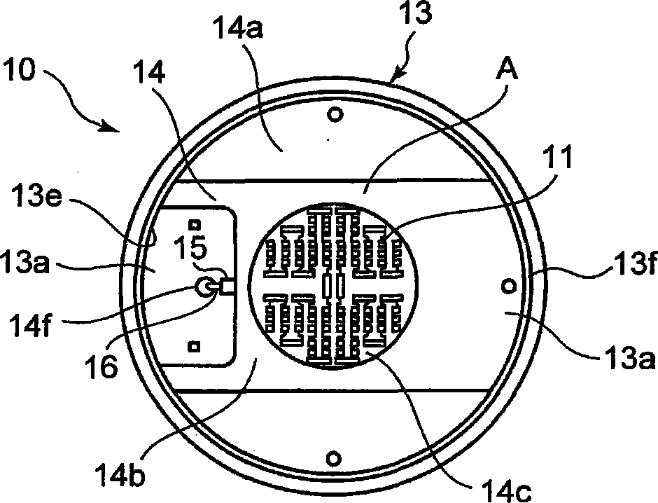
图1A表示本发明第一实施形态的附带灯口的照明灯,它是表示取下外罩构件的状态的俯视图,图1B是纵截面图。Fig. 1A shows a lamp with a cap according to the first embodiment of the present invention, which is a plan view showing a state where a cover member is removed, and Fig. 1B is a longitudinal sectional view.
图2A表示附带灯口的照明灯的基板支撑部,它是将主要部放大表示的截面图,图2B是将基板的一部分切开所表示的透视图。Fig. 2A shows a substrate supporting portion of a lighting lamp with a cap, and is an enlarged cross-sectional view showing a main part, and Fig. 2B is a perspective view showing a part of the substrate cut away.
图3是将附带灯口的照明灯的第二实例的基板支撑部的一部分切开所表示的透视图。Fig. 3 is a partially cutaway perspective view of a substrate support portion of a second example of the lamp with a base.
图4是将附带灯口的照明灯的进而第三实例的基板支撑部的一部分切开所表示的透视图。Fig. 4 is a perspective view showing a part of a board support portion of a third example of the lamp with a base cut away.
图5A是表示将本发明其他实例的附带灯口的照明灯的基板支撑部的外罩构件取下后的状态的俯视图。5A is a plan view showing a state in which a cover member of a substrate support portion of a lamp with a cap according to another example of the present invention is removed.
图5B是表示图5A所示的卡子的安装状态的概略图。Fig. 5B is a schematic view showing the mounted state of the clip shown in Fig. 5A.
图5C是概略性地表示图5A所示的实例的变形例的俯视图及截面图。FIG. 5C is a plan view and a cross-sectional view schematically showing a modified example of the example shown in FIG. 5A .
图6是概略性地表示将安装着附带灯口的照明灯的照明器具设置在天花板的状态的截面图。Fig. 6 is a cross-sectional view schematically showing a state in which a lighting fixture to which a lighting lamp with a socket is attached is installed on a ceiling.
10附带灯口的照明灯 11半导体发光元件10 Lighting lamps with
12点亮装置 12a电路基板12
12b电子零件 13主体12b
13a、13b、20a、20b、31a开口部 13c收纳部13a, 13b, 20a, 20b,
13d散热片 13e基板支撑部
13f凸条部 13g卡子13f
13h稳定夹具 14基板13h stable fixture
14a表面侧 14b绝缘层
14c圆形收纳凹部 14d密封构件14c
14e背面侧 14f插通孔14e back
15连接器 16供电用电线15
17灯口构件 17a外壳部17
17b电气绝缘部 17c眼孔部17b
18外罩构件 20绝缘盒体18
20c卡止部 20d灯口安装部
30照明器具 31器具主体30
32反射体 33插座32
A COB模块 S缝隙A COB module S gap
x-x中心轴 X天花板面x-x central axis X ceiling surface
具体实施方式Detailed ways
为更进一步阐述本发明为达成预定发明目的所采取的技术手段及功效,以下结合附图及较佳实施例,对依据本发明提出的附带灯口的照明灯及照明器具其具体实施方式、结构、特征及其功效,详细说明如后。In order to further explain the technical means and effects of the present invention to achieve the intended purpose of the invention, the specific implementation and structure of the lighting lamp with lamp socket and the lighting fixture proposed according to the present invention will be described below in conjunction with the accompanying drawings and preferred embodiments. , features and their effects are described in detail below.
下文将参考附图,描述本发明的示例性实例所提供的一种附带灯口(ferrule)的照明灯及照明器具。其中,各附图中相同的标号指的相同或对应的部分。A lighting lamp with a ferrule and lighting fixtures provided by exemplary embodiments of the present invention will be described below with reference to the accompanying drawings. Wherein, the same reference numerals in each drawing refer to the same or corresponding parts.
一实例的附带灯口的照明灯包括:中空状的导热性主体,在一端部形成着与内侧的收纳部连通的开口部,且在所述开口部周围设有基板支撑部;基板,由导热性金属板及导热性绝缘基板中的任一个构成,在一面例安装着半导体发光元件,另一面侧的周边部可导热地安装在主体的基板支撑部,并覆盖主体的开口部;点亮装置,收纳在主体内的收纳部,将半导体发光元件点亮;及灯口构件,设置在主体的另一端部侧,且连接于点亮装置。An example of a lighting lamp with a socket includes: a hollow thermally conductive body, an opening communicating with an inner storage portion is formed at one end, and a substrate supporting portion is provided around the opening; Either one of a permanent metal plate and a thermally conductive insulating substrate, a semiconductor light-emitting element is installed on one side, and the peripheral part of the other side is installed on the substrate support part of the main body in a heat-conductive manner, and covers the opening of the main body; lighting device , which is accommodated in the storage part in the main body, and lights the semiconductor light-emitting element; and the socket member, which is arranged on the other end side of the main body, and is connected to the lighting device.
以下,对本发明的附带灯口的照明灯及照明器具的实施形态加以说明。Hereinafter, embodiments of the lighting lamp with a base and the lighting fixture of the present invention will be described.
[实例1][instance 1]
如图1A、图1B及图2A、图2B所示,本实例的附带灯口的照明灯构成相当于迷你氪灯的小型附带灯口的照明灯10,且包括半导体发光元件11、将半导体发光元件11点亮的点亮装置12、一端部具有基板支撑部的主体13、安装着半导体发光元件的基板14、分别设置在主体13的一端部及另一端部侧的灯口构件17及外罩构件18。As shown in Fig. 1A, Fig. 1B and Fig. 2A, Fig. 2B, the illuminating lamp with lamp cap of this example constitutes the small-sized illuminating
半导体发光元件11在本实例中是由发光二极管(以下称为「LED」)构成,包含利用蓝色LED芯片及由所述蓝色LED芯片激发的黄色荧光体而发出白色光的高亮度、高功率的LED,所述LED具有相同性能且准备了复数个,而且主要在一方向、即LED的光轴上辐射光线。此处光轴是相对于安装着LED11的基板14的面而为大致垂直的方向。半导体发光元件11优选构成为发出白色光,但视照明器具的用途而言,可构成为发出红色光、蓝色光、绿色光等,还可以构成为组合各种颜色。此外,半导体发光元件11并不限于发光二极管,还可以使用将半导体激光(laser)、有机电致发光(electroluminescence,EL)等作为发光源的发光元件。In this example, the semiconductor
将LED11点亮的点亮装置12具有平板状电路基板12a,所述平板状电路基板12a上安装着构成所述多个LED的点亮电路的电路零件。点亮电路构成为将100V交流电压转换成24V直流电压,且向各LED11提供恒定电流的直流电流。电路基板12a构成为带状的纵长形状,在单面或两面形成着电路图案,且其安装面安装着小型电解电容器(electrolysiscondenser)等的引线(lead)零件或晶体管(transistor)等的芯片零件等、以及用来构成点亮电路的多个小型电子零件12b,下述主体13的收纳部13c内设置的绝缘盒体(case)20内,纵向收纳着电路基板12a,由此,收纳在主体13内的收纳部13c,从而构成将LED11点亮的点亮装置12。而且,在电路基板12a的输出端子上连接着用来向LED11供电的供电用电线16,在输入端子上连接着输入线(未图示)。另外,点亮装置12还可以具有用来对LED11进行调光的调光电路。The
主体13是由导热性良好的金属、本实例中是由铝构成的横截面形状为大致圆形的中空状圆筒体,且一体形成着包含空洞的收纳部13c,该空洞在一端部具有大直径的大开口部13a,在另一端部具有小直径的开口部13b。而且,一体形成着多个散热片13d,外周面形成为从一端部朝向另一端部而直径依次变小的大致圆锥状的锥(taper)面,外观构成为类似于迷你氪灯泡的颈部轮廓(silhouette)的形状,且从一端部朝向另一端部而呈辐射状突出。具有所述构成的主体13例如通过铸造、锻造或切削加工等而加工,构成为内部具有空洞的中空状圆筒体。The
在主体13的一端部的大直径的大开口部13a,以形成圆形的凹部的方式,在开口部13a的内周边一体形成呈环状的阶状的基板支撑部13e,且在所述凹部周围一体形成呈环状的凸条部13f。所述呈阶状的基板支撑部13e的表面形成为平滑面,且直接密接配置着下述板上芯片(Chip on Board,COB)模块A。In the large-diameter
借此,构成在一端部形成着与内侧的收纳部13c连通的开口部13a、且在所述开口部周围设有基板支撑部13e的中空状导热性主体13。Thereby, the hollow thermally conductive
此外,对于与中空状主体13一体形成的包含空洞的收纳部13c而言,其空洞形成为如下:内部用来配设构成点亮装置12的电路基板12a,横截面是以主体13的中心轴x-x为中心的大致圆形,内周面是与外周面的锥面大致吻合的锥面,即,随着从一端部朝向另一端部,直径依次变小而呈大致圆锥状。在所述收纳部13c内嵌入绝缘盒体20,以便实现点亮装置12与由铝形成的主体13的电气绝缘(electrical insulation)。In addition, for the
为了提高半导体发光元件11的散热性,主体13优选由导热性良好的金属形成,例如由包含铝(Al)、铜(Cu)、铁(Fe)、镍(Ni)中的至少一种的金属而形成,除此之外,也可以由氮化铝(AlN)、碳化硅(SiC)等工业材料而构成。此外,还可以由高导热树脂等合成树脂而构成。外观形状优选的是形成为从一端部朝向另一端部而直径依次变小的类似于普通白热灯泡的颈部分的轮廓的形状,这是为了提高对既存照明器具的适用性,但此处类似于普通白热灯泡并非是限制条件,并不限定于有限的特定外观形状。In order to improve the heat dissipation of the semiconductor light-emitting
绝缘盒体20是由聚对苯二甲酸丁二酯(polybutylene terephthalate,PBT)等具有耐热性及电气绝缘性的合成树脂构成,在一端部具有大直径的开口部20a,在另一端部具有小直径的开口部20b,且成为与收纳部13c的内表面形状大致吻合的从一端部朝向另一端部而直径依次变小的大致圆锥状的锥面的圆筒体,并利用螺钉或硅酮树脂或环氧树脂等粘接剂而固定在收纳部13c内。或者,还可以通过嵌入至收纳部13c内而进行安装。绝缘盒体20一体形成着在其外周面的另一端部侧呈环状凸缘而突出的卡止部20c,在从所述卡止部先突出的部分一体形成外周呈阶状的灯口安装部20d。The insulating
基板14是由呈圆板状且具有导热性的金属制、本实例中是铝制的例如厚度为0.5mm至2mm的较薄平板而构成。在基板14的一面侧、即表面侧14a积层着较薄的电气绝缘层、本实例中为白色的玻璃环氧材。此外,所述玻璃环氧材的表面形成着内周面呈大致圆形、由玻璃环氧材或硅等形成、且具有较浅的圆形收纳凹部14c的绝缘层14b。在所述较浅的圆形收纳凹部14c的底面、即基板14上的较薄电气绝缘层的表面,形成包含铜箔的布线图案。The
所述基板14是使用板上芯片(Chip On Board,COB)技术,将所述多个LED11(蓝色LED芯片)邻接于基板的收纳凹部14c的布线图案,而安装成大致矩阵状。而且,大致矩阵状规则配置的各蓝色LED芯片11与邻接的LED芯片11是通过焊线(bonding wire)而串联连接。此外,在基板14的收纳凹部14c涂布或填充着分散且混合了黄色荧光体的密封构件14d,使从所述蓝色LED芯片11辐射出的蓝色光透过,同时用蓝色光激发黄色荧光体而转换成黄色光,经透过的蓝色光和黄色光混光而辐射出白色光。借此,基板14构成为在同一面上、即表面侧14a上安装了多个LED11的COB模块A。另外,图中14f是贯穿基板14的外周边部侧而形成的用来使供电用电线16通过的插通孔。The
对于具有所述构成的由铝形成的基板14而言,其另一侧、即背面侧14e的外周边部配设成可导热地直接密接于主体13的基板支撑部13e。如图2A所示,基板14的安装着LED11的表面侧14a配置成朝向外侧,将背面侧14e的外周边部直接载置到呈平坦面的阶状基板支撑部13e并使用螺钉等固定机构,彼此密接地安装。In the
借此,构成如下金属制基板14:一面侧安装着LED11,另一面侧的周边部可导热地安装在主体13的基板支撑部13e,且覆盖主体13的开口部13a。Thereby, the
如此一来,基板14的背面侧14e确切地密接于基板支撑部13e,且基板14是由导热性良好的铝构成,两者相互结合,可以使LED11产生的热有效地传导至主体13并散热。根据所述构成,构成如下的光源部:由安装着多个LEDs11的基板14形成的COB模块A的光轴是与主体13的中心轴x-x大致吻合,且整体而言具有俯视为大致圆形的发光面。In this way, the
金属制的基板14是用来安装作为光源的半导体发光元件11的构件,例如由铝、铜、不锈钢等导热性良好的金属构成,优选的是在其表面经由硅酮树脂等电气绝缘层而形成布线图案,在所述布线图案上安装并配设半导体发光元件11,但用于安装的手段并无特别限定。而且,基板14的形状为了构成点或面模块而可以是板状圆形、四边形、六边形等的多边形状、还可以是椭圆形状等,允许能够获得所需配光特性的所有形状。The
图中15是电连接部,本实例中所述电连接部是由小型连接器(connector)构成,连接器15的输出侧端子例如利用焊接而连接在将各LED11串联布线的布线图案的输入侧,同时连接器15自身也由基板14来支撑固定。借此,连接器15配设在与基板14的插通孔14f对向且近接的位置处,同时与安装在基板14的表面侧14a的各LED11电性连接。连接器15的输入侧端子是插入连接于所述点亮装置12的输出端子的供电用电线16而连接。供电用电线16是由可插通该基板14的插通孔14f的经电气绝缘包覆的双芯细电线而构成。15 in the figure is an electrical connection part. In this example, the electrical connection part is composed of a small connector (connector), and the output side terminal of the
如图1B所示,设于主体13另一端部侧的灯口构件17是构成Edisontype的E17形的灯口,且包括具备螺纹的铜板制的筒状外壳(shell)部17a、及经由电气绝缘部17b而设在所述外壳部下端的顶部的导电性眼孔(eyelet)部17c。外壳部17a的开口部从外侧嵌入至绝缘盒体20的灯口安装部20d,通过利用硅酮树脂或环氧树脂等粘接剂的粘接或折缝(crimp)等手段,而与主体13电气绝缘,并固定在主体13的另一端部侧。外壳部17a及眼孔部17c上连接着从点亮装置12的电路基板12a的输入端子导出的输入线(未图示)。As shown in FIG. 1B, the
灯口构件17允许能够安装到安装着普通白热灯泡的插座(socket)的所有灯口,但优选为通常最普及的Edison type的E17形或E26形等的灯口。而且,并不限定于特定的灯口,可以是由金属材质构成灯口全体的灯口,由铜板等金属构成电性连接部分、由合成树脂构成其他部分的树脂制灯口,还可以是具有用于荧光灯的针形端子的灯口,具有用于悬挂式吸顶灯的L字形端子的灯口。The
外罩构件18是由灯罩构成,其具有透光性,例如由厚度小的玻璃或聚碳酸酯等合成树脂而构成,由具有透明或光扩散性的乳白色等半透明、此处为乳白色的聚碳酸酯而形成为在一端部具有开口18a的类似于迷你氪灯泡轮廓的圆滑曲面状。外罩构件18将开口18a的开口端部以覆盖由COB模块A形成的基板14的发光面的方式而嵌入至基板支撑部13e的凸条部13f内,例如利用硅酮树脂或环氧树脂等粘接剂进行固定。借此,变成主体13的倾斜外周面一体地与灯罩18的曲面状外周面大致连续的外观形状,构成为类似迷你氪灯泡轮廓的形状。The
接下来,对具有所述构成的球形的附带灯口的照明灯10的组装步骤进行说明。首先,将绝缘盒体20从主体13的一端部的大开口部13a处嵌入收纳部13c内,在绝缘盒体20的外周面与收纳部13c内周面的接触部分涂布粘接材而加以固定。此时,绝缘盒体20的大开口部20a位于与主体13的基板支撑部13e的阶部同一平面,或者位于开口部20a的少许下方。另外,基板14发挥防止绝缘盒体20微小移动的作用。也可以不在绝缘盒体20的外周面与收纳部13c之间涂布粘接材,而是通过以基板14来按压而安装绝缘盒体20。Next, an assembly procedure of the spherical capped illuminating
接下来,将点亮装置12的电路基板12a纵向放置,且从绝缘盒体20的大开口部20a处插入到绝缘盒体20内,使与绝缘盒体20内表面的引导槽嵌合而进行支撑收纳。此时预先从大开口部20a向外侧抽出预先连接于电路基板12a的输出端子的供电用电线16的前端。Next, place the
接下来,将从开口部20a抽出的供电用电线16从基板14的背面侧14e通过插通孔14f,然后将其前端抽出到基板14的表面侧14a。Next, the
接下来,将基板14的安装着LED11的表面侧14a配置成面向外侧,将背面侧14e的外周边部直接载置到呈平坦面的阶状基板支撑部13e,使基板14覆盖开口部13a的整体,以此方式安装基板14,并使用四根螺钉将其彼此密接固定(图2B)。Next, the
接下来,将已从插通孔14f抽出且绝缘包覆已剥离的供电用电线16的前端插入至连接器15而加以连接。Next, the front end of the power supply
接下来,将从点亮装置12的电路基板12a的输入端子导出的输入线(未图示),连接于灯口构件17的外壳部17a及眼孔部17c,并在连接状态下将外壳部17a的开口部嵌入至绝缘盒体20的灯口安装部20d,且利用粘接剂进行固着。Next, the input line (not shown) derived from the input terminal of the
接下来,准备外罩构件18,以覆盖安装于主体13的基板14的LED11的方式而罩住,将开口18a的开口端部嵌入主体的凸条部13f内,并在与凸条部抵接的部分涂布粘接剂而加以固定。借此,构成在一端部具有外罩构件18即灯罩、在另一端部设有E17形的灯口构件17,且整体外观形状类似于迷你氪灯泡轮廓的小型灯泡形的附带灯口的照明灯10。Next, the
以上,根据本实例,作为附带灯口的照明灯,是在基板14的表面侧14a利用COB将多个LED11大致矩阵状规则地配置而进行安装,所以从各LED11辐射出的光能够朝向外罩构件18的整个内表面而大致均等地辐射,由乳白色的灯罩将光扩散后,进行具有类似迷你氪灯泡的配光特性的照明。As mentioned above, according to the present example, as the lighting lamp with a cap, a plurality of
而且,各LED11产生的热从由铝形成的基板14传导至基板直接密接固定的基板支撑部13e,然后从由铝形成的主体13经由散热片13d而有效地向外部散热。此时,并未如专利文献所述般、在配置着LED的基板与由铝形成的主体之间,设置散热用的由铝形成的基台。因此,不会因由其他零件形成的基台而导致热阻增加,从而可以使LED的热进一步有效地散热。Furthermore, heat generated by each
此外,铝制的基板14是构成为在同一面上安装着多个LED11的COB模块,故可如所述般进行具有类似迷你氪灯泡的配光特性的照明,并且通过抑制所述LED11与主体13之间的热阻而带来的有效散热作用,可以抑制LED11的温度上升。In addition, since the
通过所述有效的散热作用,可以提供一种如下附带灯口的照明灯:可防止各LED11的温度上升及温度不均,可抑制发光效率的下降,且可防止因光束减少带来的照度下降,而且可以充分获得预定的白热灯泡水平的光束。同时,可以实现LED的长寿命化。此外,未使用所述专利文献所示的其他零件的基台便可进行有效的散热,故可提供一种在成本方面也有利的附带灯口的照明灯及照明器具。Through the above-mentioned effective heat dissipation, it is possible to provide a lighting lamp with a lamp socket that can prevent the temperature rise and temperature unevenness of each
而且,在组装附带灯口的照明灯时,绝缘盒体20向主体13的嵌入作业、点亮装置12的电路基板12a向绝缘盒体20的收纳作业、基板14向基板支撑部13e的固定作业、及供电用电线16向连接器15的连接作业,均可在主体13的一端部的大开口部13a侧进行,因此所述多个作业可以实现自动化,从而可进一步降低成本。In addition, when assembling the lighting lamp with a cap, the insertion operation of the insulating
此外,基板14相对于在主体13的大开口部13a的内周边呈环状的阶状的基板支撑部13e而直接密接地配置,因此主体13可以形成为内周面呈与外周面的锥面大致吻合、即,从一端部朝向另一端部而直径依次变小的大致圆锥状的锥面的中空状空洞,可减轻主体13自身重量,同时在空洞内形成用来收纳点亮装置12的宽广空间,从而也可应对为获得更高功率而大型化的点亮装置12。In addition, since the
而且,也可以在基板14的背面侧14e的外周边部与阶状的基板支撑部13e之间,填充由导热性良好的硅酮树脂或环氧树脂等形成的粘接剂,使其密接而进行安装。借此,可以更确切地实现基板14与基板支撑部13e之间的电气绝缘,同时可以防止基板14与基板支撑部13e之间产生缝隙,从而可更密接地安装。Furthermore, between the outer peripheral portion of the
另外,在附带灯口的照明灯的主体13中,也可以将露在外侧的外面部分形成为例如凹凸或缎纹状以增大表面积,或者实施涂白或白色防蚀铝处理以提高外面部分的热辐射率。而且,在实施涂白或白色防蚀铝处理的情况下,将球形的附带灯口的照明灯10安装到照明器具上并将其点亮时,露在外面的铝制的主体13外面的反射率变高,从而可提高器具效率,且外观、设计均变得良好,还可以提高商品性。此外,外罩构件也可以由用来从外部保护LED的充电部等的透明或半透明的保护外罩而构成。In addition, in the
[实例2][Example 2]
以上,在实例1中基板14是由呈圆板状的铝制较薄平板而构成,但如图3所示,也可以构成为将四角切割的大致正方形的形状。根据该构成,将基板14载置到基板支撑部13e以进行固定时,在基板14的经切割的直线部分与环状的基板支撑部13e之间形成缝隙S。利用所述缝隙S而插通供电用电线16的前端,可连接于连接器15,在基板14上形成插通孔14f的步骤成为不需要,对于成本方面也有利。As mentioned above, in Example 1, the board|
[实例3][Example 3]
在实例1中基板是构成为COB模块A,但如图4所示,也可以构成为在由金属形成的基板上表面安装LED的表面安装元件(surface mount device,SMD)封装。这种情况下,基板14例如由铝构成,其表面经由硅酮树脂等电气绝缘层而形成包含铜箔的布线图案,并在所述布线图案上大致等间隔地将四个LED11安装配设成大致同心圆状。另外,各LED11是通过布线图案而串联连接。In Example 1, the substrate is configured as a COB module A, but as shown in FIG. 4, it may also be configured as a surface mount device (SMD) package in which LEDs are surface-mounted on a metal substrate. In this case, the
使具有所述构成且构成为SMD封装的基板14与上述内容同样地直接密接于主体13的呈阶状的基板支撑部13e而进行支撑。此时,如图4所示,通过使用四角经切割的基板,而在基板14的经切割的直线部分与环状的基板支撑部13e之间形成缝隙S,因此供电用电线16利用所述缝隙S而插通其前端,可连接于连接器15。The board|
根据所述构成,虽然基板14与基板支撑部13e在缝隙S的部分不接触而使得接触面积变少,但在SMD封装的情况下,LED的使用个数也少,能够抑制温度上升,且各LED11是配置在靠近外周边部的位置、即,靠近基板支撑部13e的位置处,因此可以使各LED11的热有效地导热至基板支撑部13e,从而可以充分地对LED11的热进行散热。同时,在基板14形成插通孔14f的步骤成为不需要,从而可以提供一种在成本方面也有利的附带灯口的照明灯。另外,在SMD封装的情况下,LED11优选为构成多个,视照明用途而选择必要个数,例如可以构成四个左右的元件组群,也可以将所述组群构成为一个或多个。此外,也可以由一个LED11构成。According to the above configuration, although the
另外,在所述实例中,是使用导热性佳的金属铝作为基板14,但也可以使用陶瓷基板来作为导热性佳的绝缘性基板。但是,当利用螺钉将由陶瓷形成的基板14固定到基板支撑部13e时,若直接用螺钉进行固定,则会因螺钉的紧固扭矩(torque)、及由铝形成的基板支撑部13e与陶瓷基板14的热膨胀系数差,而引起基板14产生龟裂的情况,这样对于品质而言并不佳。为了防止所述龟裂的产生,如图5A、图5B所示,可以利用弹簧的原理结构,在螺钉与基板14之间经由利用弹力按压的卡子13g而将两者固定。In addition, in the above example, metal aluminum with good thermal conductivity is used as the
利用所述卡子13g,吸收因基板14与基板支撑部13e的热膨胀系数的差异引起的应力(stress),从而可以防止陶瓷基板14产生龟裂。然而,在使用所述卡子13g时,也考虑基板14的固定位置逐渐移动而产生光学问题的情况。因此,如图5C所示,可以使用结构类似于在基板14侧面按压的卡子13g的稳定夹具13h。即,为了防止移动的基板14与形成为四边形的凹状的基板支撑部13e的侧壁每当热膨胀时便冲突而损坏基板14,基板14优选为使用所述卡子13g、稳定夹具13h此两者。此处,陶瓷基板14是持有余裕地配置在基板支撑部13e。即,在四边形的基板支撑部13e的两边抵接陶瓷基板14的两边,另外两边则按压防走滑用的稳定夹具13h,借此进行定位及固定。因此,抵抗该稳定夹具13h的弹力,陶瓷基板14虽会变形,但不至于破损。The
接下来,对将以此方式构成的附带灯口的照明灯10用作光源的照明器具的构成进行说明。如图6所示,30是筒灯式既存的照明器具,嵌入设置在店铺等的天花板面X上,以具有E17形灯口的迷你氪灯作为光源,且包括:器具主体31,呈下表面具有开口部31a的金属制箱状;金属制的反射体32,嵌合于开口部31a;及插座33,可以将迷你氪灯的E17形灯口拧入。反射体32例如由不锈钢等金属板构成,且在反射体32的上面板中央部设置着插座33。Next, the configuration of a lighting fixture using the
在具有所述构成的迷你氪灯用的既存的照明器具30中,为实现节能或长寿命化等,而使用所述将LED11作为光源的小型球形的附带灯口的照明灯10来代替迷你氪灯。即,附带灯口的照明灯10是将灯口构件17形成为E17形,因此可以直接插入到所述照明器具30的迷你氪灯用的插座33。此时,附带灯口的照明灯10的外周面呈大致圆锥状的锥面,外观构成为类似迷你氪灯的颈部轮廓的形状,因此可以顺畅地插入而不会产生颈部碰到插座周边的反射体32等的情况,使球形的附带灯口的照明灯10向既存照明器具的适用率提高。借此,可以构成将LED11作为光源的节能形筒灯。In the existing
若将所述构成的筒灯接通电源,则从插座33经由附带灯口的照明灯10的灯口构件17而供给电源,点亮装置12开始动作,输出24V的直流电压。所述直流电压从连接于点亮装置12的输出端子的供电用电线16施加给经由连接器15而串联连接的LED11,以供给恒定电流的直流电流。借此,所有LED11同时点亮而辐射出白色光。When the downlight configured as described above is powered on, power is supplied from the
同时,若球形的附带灯口的照明灯10点亮,则LED11的温度上升并产生热。所述热从导热性良好的由铝形成的基板14传导至直接密接固定有基板14的基板支撑部13e,并从由铝形成的主体13经由散热片13d而有效地向外部散热。At the same time, when the
特别是成为光源的附带灯口的照明灯10的配光是接近于迷你氪灯的配光,借此使朝向照相照明器具30内配置的插座33附近的反射体32的光的照射量增大,从而可以构成照射量达到构成为迷你氪灯用的反射体32的光学设计程度,且可抑制光输出的下降、寿命也长的照明器具。In particular, the light distribution of the illuminating
在本发明中,照明器具允许是天花板嵌入形、直接安装形、悬挂形、及壁面安装形等,可以在器具主体上安装灯罩、遮光物(shade)、反射体等作为制光体,也可以将作为光源的附带灯口的照明灯露出。此外,并不限于在器具主体上安装一个附带灯口的照明灯,也可以配设多个。而且,也可以构成办公室等设施、业务用的大型照明器具等。In the present invention, the lighting fixtures are allowed to be ceiling-embedded, directly installed, suspended, and wall-mounted, etc., and lampshades, shades, reflectors, etc. can be installed on the main body of the fixture as light control bodies, or Expose the lamp with the socket as the light source. In addition, it is not limited to attaching one lighting lamp with a socket to the apparatus main body, and it is also possible to arrange a plurality of them. Furthermore, facilities such as offices and large-scale lighting fixtures for business use may also be configured.
在本发明中,附带灯口的照明灯可以构成为类似普通白热灯泡的形状的灯泡形的附带灯口的照明灯(A形或PS形)、球形的附带灯口的照明灯(G形)、圆筒形的附带灯口的照明灯(T形)、反射形的附带灯口的照明灯(R形)等。此外,还可以构成为无灯罩的附带灯口的照明灯。而且,本发明并不限于类似普通白热灯泡的形状的附带灯口的照明灯,也可以适用于其他各种外观形状、用途的附带灯口的照明灯。In the present invention, the lighting lamp with the lamp socket can be constituted as a bulb-shaped lighting lamp with the lamp socket (A shape or PS shape), a spherical lighting lamp with the socket (G shape) similar to the shape of an ordinary incandescent light bulb. ), cylindrical lighting lamps with lamp sockets (T shape), reflective lamps with lamp sockets (R shape), etc. In addition, it can also be configured as an illuminating lamp with a socket without a lampshade. Moreover, the present invention is not limited to the lighting lamp with a cap having a shape similar to an ordinary incandescent light bulb, and can also be applied to lighting lamps with a cap with various appearance shapes and uses.
虽然已描述了某些实例,但这些实例仅以实例方式呈现,且并非旨在限制本发明的范围。实际上,可在不脱离本发明精神的情况下修改所述结构元件。可通过适当地组合所述实例中所揭示的结构元件而制作各种实例。例如,可从所述实例中揭示的所有结构元件中省去一些结构元件。此外,可适当地组合不同实例中的结构元件。所附权利要求书及其等同物旨在涵盖此类将属于本发明范围和精神的形式或修改。While certain examples have been described, these examples have been presented by way of example only, and are not intended to limit the scope of the inventions. In fact, the structural elements may be modified without departing from the spirit of the invention. Various examples can be produced by appropriately combining structural elements disclosed in the examples. For example, some structural elements may be omitted from all structural elements disclosed in the examples. Also, structural elements in different examples may be combined as appropriate. The appended claims and their equivalents are intended to cover such forms or modifications as would fall within the scope and spirit of the invention.
Claims (14)
Applications Claiming Priority (2)
| Application Number | Priority Date | Filing Date | Title |
|---|---|---|---|
| JP2009-220433 | 2009-09-25 | ||
| JP2009220433 | 2009-09-25 |
Publications (2)
| Publication Number | Publication Date |
|---|---|
| CN102032481A CN102032481A (en) | 2011-04-27 |
| CN102032481B true CN102032481B (en) | 2014-01-08 |
Family
ID=43302880
Family Applications (1)
| Application Number | Title | Priority Date | Filing Date |
|---|---|---|---|
| CN201010292771.4A Expired - Fee Related CN102032481B (en) | 2009-09-25 | 2010-09-20 | Lamp with base and lighting equipment |
Country Status (4)
| Country | Link |
|---|---|
| US (1) | US8395304B2 (en) |
| EP (1) | EP2302286A3 (en) |
| JP (1) | JP5578361B2 (en) |
| CN (1) | CN102032481B (en) |
Families Citing this family (67)
| Publication number | Priority date | Publication date | Assignee | Title |
|---|---|---|---|---|
| US7758223B2 (en) | 2005-04-08 | 2010-07-20 | Toshiba Lighting & Technology Corporation | Lamp having outer shell to radiate heat of light source |
| US9412926B2 (en) * | 2005-06-10 | 2016-08-09 | Cree, Inc. | High power solid-state lamp |
| US8294356B2 (en) | 2008-06-27 | 2012-10-23 | Toshiba Lighting & Technology Corporation | Light-emitting element lamp and lighting equipment |
| JP5333758B2 (en) | 2009-02-27 | 2013-11-06 | 東芝ライテック株式会社 | Lighting device and lighting fixture |
| JP2011049527A (en) * | 2009-07-29 | 2011-03-10 | Toshiba Lighting & Technology Corp | Led lighting equipment |
| JP5601512B2 (en) | 2009-09-14 | 2014-10-08 | 東芝ライテック株式会社 | Light emitting device and lighting device |
| JP2011091033A (en) | 2009-09-25 | 2011-05-06 | Toshiba Lighting & Technology Corp | Light-emitting module, bulb-shaped lamp and lighting equipment |
| US8324789B2 (en) | 2009-09-25 | 2012-12-04 | Toshiba Lighting & Technology Corporation | Self-ballasted lamp and lighting equipment |
| CN102032480B (en) | 2009-09-25 | 2013-07-31 | 东芝照明技术株式会社 | Self-ballasted lamp and lighting equipment |
| JP5257622B2 (en) * | 2010-02-26 | 2013-08-07 | 東芝ライテック株式会社 | Light bulb shaped lamp and lighting equipment |
| US9310030B2 (en) | 2010-03-03 | 2016-04-12 | Cree, Inc. | Non-uniform diffuser to scatter light into uniform emission pattern |
| US9625105B2 (en) * | 2010-03-03 | 2017-04-18 | Cree, Inc. | LED lamp with active cooling element |
| US9316361B2 (en) | 2010-03-03 | 2016-04-19 | Cree, Inc. | LED lamp with remote phosphor and diffuser configuration |
| US9062830B2 (en) * | 2010-03-03 | 2015-06-23 | Cree, Inc. | High efficiency solid state lamp and bulb |
| US8562161B2 (en) | 2010-03-03 | 2013-10-22 | Cree, Inc. | LED based pedestal-type lighting structure |
| US9024517B2 (en) * | 2010-03-03 | 2015-05-05 | Cree, Inc. | LED lamp with remote phosphor and diffuser configuration utilizing red emitters |
| US8931933B2 (en) * | 2010-03-03 | 2015-01-13 | Cree, Inc. | LED lamp with active cooling element |
| US9275979B2 (en) | 2010-03-03 | 2016-03-01 | Cree, Inc. | Enhanced color rendering index emitter through phosphor separation |
| US10359151B2 (en) | 2010-03-03 | 2019-07-23 | Ideal Industries Lighting Llc | Solid state lamp with thermal spreading elements and light directing optics |
| US9057511B2 (en) | 2010-03-03 | 2015-06-16 | Cree, Inc. | High efficiency solid state lamp and bulb |
| US9500325B2 (en) | 2010-03-03 | 2016-11-22 | Cree, Inc. | LED lamp incorporating remote phosphor with heat dissipation features |
| US8058782B2 (en) * | 2010-03-10 | 2011-11-15 | Chicony Power Technology Co., Ltd. | Bulb-type LED lamp |
| JP4914511B2 (en) * | 2010-04-20 | 2012-04-11 | シャープ株式会社 | Lighting device |
| US10451251B2 (en) | 2010-08-02 | 2019-10-22 | Ideal Industries Lighting, LLC | Solid state lamp with light directing optics and diffuser |
| KR101441261B1 (en) * | 2010-09-27 | 2014-09-17 | 도시바 라이텍쿠 가부시키가이샤 | Lightbulb-formed lamp and illumination apparatus |
| JP5677806B2 (en) * | 2010-11-02 | 2015-02-25 | ローム株式会社 | LED bulb |
| US8564000B2 (en) | 2010-11-22 | 2013-10-22 | Cree, Inc. | Light emitting devices for light emitting diodes (LEDs) |
| US9490235B2 (en) | 2010-11-22 | 2016-11-08 | Cree, Inc. | Light emitting devices, systems, and methods |
| US9300062B2 (en) | 2010-11-22 | 2016-03-29 | Cree, Inc. | Attachment devices and methods for light emitting devices |
| US8624271B2 (en) | 2010-11-22 | 2014-01-07 | Cree, Inc. | Light emitting devices |
| US9234655B2 (en) | 2011-02-07 | 2016-01-12 | Cree, Inc. | Lamp with remote LED light source and heat dissipating elements |
| US9068701B2 (en) * | 2012-01-26 | 2015-06-30 | Cree, Inc. | Lamp structure with remote LED light source |
| US11251164B2 (en) | 2011-02-16 | 2022-02-15 | Creeled, Inc. | Multi-layer conversion material for down conversion in solid state lighting |
| KR20120110284A (en) * | 2011-03-29 | 2012-10-10 | 삼성디스플레이 주식회사 | Light emitting module and backlight assembly having the same |
| WO2012136578A1 (en) * | 2011-04-04 | 2012-10-11 | Ceramtec Gmbh | Led lamp comprising an led as the luminaire and a glass or plastic lampshade |
| JP2012248687A (en) * | 2011-05-27 | 2012-12-13 | Toshiba Lighting & Technology Corp | Light-emitting module and illumination apparatus |
| TWM419877U (en) * | 2011-06-03 | 2012-01-01 | Chen-Lung Huang | Heat-dissipation structure of LED light bulb |
| JP2013026206A (en) * | 2011-07-22 | 2013-02-04 | Du Pont Kk | Structure of led lighting fixture |
| DE102011084365A1 (en) * | 2011-10-12 | 2013-04-18 | Osram Gmbh | LED module with a heat sink |
| CN104081112B (en) | 2011-11-07 | 2016-03-16 | 克利公司 | High voltage array light emitting diode (LED) device, apparatus and method |
| TW201331503A (en) * | 2012-01-20 | 2013-08-01 | Taiwan Fu Hsing Ind Co Ltd | Lighting structure and a fixing base thereof |
| CN204127690U (en) * | 2012-02-17 | 2015-01-28 | 松下电器产业株式会社 | Light source device for lighting |
| US9488359B2 (en) | 2012-03-26 | 2016-11-08 | Cree, Inc. | Passive phase change radiators for LED lamps and fixtures |
| US10134961B2 (en) | 2012-03-30 | 2018-11-20 | Cree, Inc. | Submount based surface mount device (SMD) light emitter components and methods |
| US9735198B2 (en) | 2012-03-30 | 2017-08-15 | Cree, Inc. | Substrate based light emitter devices, components, and related methods |
| JP6137439B2 (en) * | 2012-04-09 | 2017-05-31 | Nok株式会社 | Insulated heat radiation rubber molding |
| JP2013251139A (en) * | 2012-05-31 | 2013-12-12 | Funai Electric Co Ltd | Lighting device |
| US20140016317A1 (en) * | 2012-07-16 | 2014-01-16 | Jst Performance, Inc. Dba Rigid Industries | Landing light |
| JPWO2014104155A1 (en) * | 2012-12-28 | 2017-01-12 | 信越化学工業株式会社 | Light emitting device |
| JP6075542B2 (en) * | 2013-02-20 | 2017-02-08 | 東芝ライテック株式会社 | Light emitting device and lighting device |
| US9506612B1 (en) * | 2013-03-15 | 2016-11-29 | Cooper Technologies Company | Emergency lighting for light emitting diode fixtures |
| JP6191907B2 (en) * | 2013-04-19 | 2017-09-06 | パナソニックIpマネジメント株式会社 | LIGHTING DEVICE AND BASE DESIGN METHOD |
| US9360188B2 (en) | 2014-02-20 | 2016-06-07 | Cree, Inc. | Remote phosphor element filled with transparent material and method for forming multisection optical elements |
| JP6402481B2 (en) * | 2014-04-30 | 2018-10-10 | 株式会社Ihi | Combustion heater |
| TWI506227B (en) * | 2014-08-05 | 2015-11-01 | Lite On Technology Corp | Light-emitting device |
| WO2016156057A1 (en) * | 2015-03-30 | 2016-10-06 | Philips Lighting Holding B.V. | Lighting device with improved thermal performancespec |
| DE102015206802A1 (en) * | 2015-04-15 | 2016-10-20 | Osram Gmbh | Lamp with LEDs |
| DE102015206797A1 (en) * | 2015-04-15 | 2016-10-20 | Osram Gmbh | Lamp with LEDs |
| US20170175990A1 (en) * | 2015-12-16 | 2017-06-22 | Jitendra Patel | Led array apparatus |
| US20170307178A1 (en) * | 2016-04-25 | 2017-10-26 | Auroralight, Inc. | Outdoor Light and related methods |
| FR3050802B1 (en) * | 2016-04-29 | 2020-03-06 | Valeo Vision | LIGHT DEVICE WITH HEAT DISSIPATION DEVICE |
| USD823492S1 (en) | 2016-10-04 | 2018-07-17 | Cree, Inc. | Light emitting device |
| CN206918825U (en) * | 2017-04-25 | 2018-01-23 | 漳州立达信光电子科技有限公司 | A split downlight |
| CN108426209B (en) * | 2018-03-07 | 2023-07-28 | 欧普照明股份有限公司 | Light emitting module, lighting device and ceiling lamp |
| EP3754254B1 (en) * | 2019-06-19 | 2021-10-13 | Leedarson Lighting Co., Ltd. | Lighting apparatus |
| US11168879B2 (en) * | 2020-02-28 | 2021-11-09 | Omachron Intellectual Property Inc. | Light source |
| CN211694514U (en) * | 2020-02-28 | 2020-10-16 | 漳州立达信光电子科技有限公司 | lighting fixtures |
Citations (1)
| Publication number | Priority date | Publication date | Assignee | Title |
|---|---|---|---|---|
| WO2006118457A1 (en) * | 2005-04-01 | 2006-11-09 | Lemnis Lighting Ip Gmbh | Heat sink, lamp and method for manufacturing a heat sink |
Family Cites Families (160)
| Publication number | Priority date | Publication date | Assignee | Title |
|---|---|---|---|---|
| US534665A (en) * | 1895-02-26 | Method of casting projectiles | ||
| US534038A (en) * | 1895-02-12 | Dynamo-electric machine | ||
| US356107A (en) * | 1887-01-18 | Ella b | ||
| US1972790A (en) * | 1932-07-15 | 1934-09-04 | Crouse Hinds Co | Electric hand lamp |
| GB1601461A (en) * | 1977-05-21 | 1981-10-28 | Amp Inc | Electrical junction box |
| US4503360A (en) * | 1982-07-26 | 1985-03-05 | North American Philips Lighting Corporation | Compact fluorescent lamp unit having segregated air-cooling means |
| JPH071374B2 (en) | 1984-03-06 | 1995-01-11 | 株式会社ニコン | Light source |
| US4939420A (en) * | 1987-04-06 | 1990-07-03 | Lim Kenneth S | Fluorescent reflector lamp assembly |
| USD356107S (en) | 1992-05-15 | 1995-03-07 | Fujitsu Limited | Developing cartridge for copier |
| JP2662488B2 (en) * | 1992-12-04 | 1997-10-15 | 株式会社小糸製作所 | Seal structure between front lens leg and seal groove in automotive lighting |
| US5327332A (en) * | 1993-04-29 | 1994-07-05 | Hafemeister Beverly J | Decorative light socket extension |
| US5632551A (en) * | 1994-07-18 | 1997-05-27 | Grote Industries, Inc. | LED vehicle lamp assembly |
| US5537301A (en) * | 1994-09-01 | 1996-07-16 | Pacific Scientific Company | Fluorescent lamp heat-dissipating apparatus |
| US5585697A (en) | 1994-11-17 | 1996-12-17 | General Electric Company | PAR lamp having an integral photoelectric circuit arrangement |
| US6465743B1 (en) | 1994-12-05 | 2002-10-15 | Motorola, Inc. | Multi-strand substrate for ball-grid array assemblies and method |
| DE69614693T2 (en) * | 1995-06-29 | 2002-06-20 | Siemens Microelectronics Inc | TARGETED LIGHTING USING TIR TECHNOLOGY |
| US6095668A (en) * | 1996-06-19 | 2000-08-01 | Radiant Imaging, Inc. | Incandescent visual display system having a shaped reflector |
| US5785418A (en) * | 1996-06-27 | 1998-07-28 | Hochstein; Peter A. | Thermally protected LED array |
| US5857767A (en) * | 1996-09-23 | 1999-01-12 | Relume Corporation | Thermal management system for L.E.D. arrays |
| JPH1125919A (en) * | 1997-07-04 | 1999-01-29 | Moriyama Sangyo Kk | Bulb and lighting equipment |
| US5947588A (en) * | 1997-10-06 | 1999-09-07 | Grand General Accessories Manufacturing Inc. | Light fixture with an LED light bulb having a conventional connection post |
| JP2000083343A (en) | 1998-09-03 | 2000-03-21 | Mitsubishi Electric Corp | Motor frame and method of manufacturing motor frame |
| DE69936375T2 (en) | 1998-09-17 | 2008-02-28 | Koninklijke Philips Electronics N.V. | LED LIGHT |
| JP3753291B2 (en) | 1998-09-30 | 2006-03-08 | 東芝ライテック株式会社 | Light bulb shaped fluorescent lamp |
| US6502968B1 (en) * | 1998-12-22 | 2003-01-07 | Mannesmann Vdo Ag | Printed circuit board having a light source |
| US6186646B1 (en) * | 1999-03-24 | 2001-02-13 | Hinkley Lighting Incorporated | Lighting fixture having three sockets electrically connected and mounted to bowl and cover plate |
| JP2000294434A (en) * | 1999-04-02 | 2000-10-20 | Hanshin Electric Co Ltd | Internal combustion engine ignition coil |
| US6227679B1 (en) * | 1999-09-16 | 2001-05-08 | Mule Lighting Inc | Led light bulb |
| US6525455B1 (en) | 1999-09-22 | 2003-02-25 | Matsushita Electric Industrial Co., Ltd. | Bulb-form lamp and its manufacturing method |
| US6161910A (en) | 1999-12-14 | 2000-12-19 | Aerospace Lighting Corporation | LED reading light |
| JP2001243809A (en) | 2000-02-28 | 2001-09-07 | Mitsubishi Electric Lighting Corp | Led electric bulb |
| US6814470B2 (en) * | 2000-05-08 | 2004-11-09 | Farlight Llc | Highly efficient LED lamp |
| US6626554B2 (en) * | 2000-05-18 | 2003-09-30 | Aaron Nathan Rincover | Light apparatus |
| US7122900B2 (en) * | 2000-06-26 | 2006-10-17 | Renesas Technology Corp. | Semiconductor device and method manufacturing the same |
| JP2002075011A (en) * | 2000-08-30 | 2002-03-15 | Matsushita Electric Ind Co Ltd | Tube ball |
| US6517217B1 (en) * | 2000-09-18 | 2003-02-11 | Hwa Hsia Glass Co., Ltd. | Ornamental solar lamp assembly |
| JP2002280617A (en) | 2001-03-19 | 2002-09-27 | Matsushita Electric Ind Co Ltd | Lighting equipment |
| US6598996B1 (en) * | 2001-04-27 | 2003-07-29 | Pervaiz Lodhie | LED light bulb |
| CN2489462Y (en) * | 2001-06-17 | 2002-05-01 | 广东伟雄集团有限公司 | Energy-saving lamp with insert strip |
| JP4674418B2 (en) | 2001-06-29 | 2011-04-20 | パナソニック株式会社 | Lighting equipment |
| JP4076329B2 (en) | 2001-08-13 | 2008-04-16 | エイテックス株式会社 | LED bulb |
| US6866401B2 (en) * | 2001-12-21 | 2005-03-15 | General Electric Company | Zoomable spot module |
| US6682211B2 (en) * | 2001-09-28 | 2004-01-27 | Osram Sylvania Inc. | Replaceable LED lamp capsule |
| JP2003115203A (en) * | 2001-10-03 | 2003-04-18 | Matsushita Electric Ind Co Ltd | Low pressure mercury vapor discharge lamp and method of manufacturing the same |
| US6525668B1 (en) * | 2001-10-10 | 2003-02-25 | Twr Lighting, Inc. | LED array warning light system |
| US6942365B2 (en) * | 2002-12-10 | 2005-09-13 | Robert Galli | LED lighting assembly |
| EP1467414A4 (en) | 2001-12-29 | 2007-07-11 | Hangzhou Fuyang Xinying Dianzi | A led and led lamp |
| US6936855B1 (en) * | 2002-01-16 | 2005-08-30 | Shane Harrah | Bendable high flux LED array |
| US6685339B2 (en) * | 2002-02-14 | 2004-02-03 | Polaris Pool Systems, Inc. | Sparkle light bulb with controllable memory function |
| US6641283B1 (en) | 2002-04-12 | 2003-11-04 | Gelcore, Llc | LED puck light with detachable base |
| US6824296B2 (en) * | 2002-07-02 | 2004-11-30 | Leviton Manufacturing Co., Inc. | Night light assembly |
| US20040012955A1 (en) * | 2002-07-17 | 2004-01-22 | Wen-Chang Hsieh | Flashlight |
| US20040023815A1 (en) * | 2002-08-01 | 2004-02-05 | Burts Boyce Donald | Lost circulation additive, lost circulation treatment fluid made therefrom, and method of minimizing lost circulation in a subterranean formation |
| JP4123886B2 (en) | 2002-09-24 | 2008-07-23 | 東芝ライテック株式会社 | LED lighting device |
| US6787999B2 (en) * | 2002-10-03 | 2004-09-07 | Gelcore, Llc | LED-based modular lamp |
| US7111961B2 (en) * | 2002-11-19 | 2006-09-26 | Automatic Power, Inc. | High flux LED lighting device |
| US7188980B2 (en) * | 2002-12-02 | 2007-03-13 | Honda Motor Co., Ltd. | Head light system |
| US7153004B2 (en) * | 2002-12-10 | 2006-12-26 | Galli Robert D | Flashlight housing |
| JP2004193053A (en) | 2002-12-13 | 2004-07-08 | Toshiba Lighting & Technology Corp | Compact fluorescent lamps and lighting equipment |
| US6964501B2 (en) * | 2002-12-24 | 2005-11-15 | Altman Stage Lighting Co., Ltd. | Peltier-cooled LED lighting assembly |
| JP4038136B2 (en) | 2003-01-13 | 2008-01-23 | シーシーエス株式会社 | Spot lighting device using power LED |
| EP1447619A1 (en) * | 2003-02-12 | 2004-08-18 | Exterieur Vert S.A. | Lighting device, in particular projector-like sealed luminaire recessed in the ground, cooled by air circulation |
| CN2637885Y (en) * | 2003-02-20 | 2004-09-01 | 高勇 | LED lamp bulb with luminous curved surface |
| JP3885032B2 (en) | 2003-02-28 | 2007-02-21 | 松下電器産業株式会社 | Fluorescent lamp |
| AU2003902031A0 (en) * | 2003-04-29 | 2003-05-15 | Eveready Battery Company, Inc | Lighting device |
| US6921181B2 (en) * | 2003-07-07 | 2005-07-26 | Mei-Feng Yen | Flashlight with heat-dissipation device |
| US7679096B1 (en) * | 2003-08-21 | 2010-03-16 | Opto Technology, Inc. | Integrated LED heat sink |
| US7300173B2 (en) | 2004-04-08 | 2007-11-27 | Technology Assessment Group, Inc. | Replacement illumination device for a miniature flashlight bulb |
| US7329024B2 (en) * | 2003-09-22 | 2008-02-12 | Permlight Products, Inc. | Lighting apparatus |
| US6942360B2 (en) * | 2003-10-01 | 2005-09-13 | Enertron, Inc. | Methods and apparatus for an LED light engine |
| US6982518B2 (en) * | 2003-10-01 | 2006-01-03 | Enertron, Inc. | Methods and apparatus for an LED light |
| US7144135B2 (en) * | 2003-11-26 | 2006-12-05 | Philips Lumileds Lighting Company, Llc | LED lamp heat sink |
| JP2005166578A (en) | 2003-12-05 | 2005-06-23 | Hamai Denkyu Kogyo Kk | Light bulb shaped LED lamp |
| US7281818B2 (en) * | 2003-12-11 | 2007-10-16 | Dialight Corporation | Light reflector device for light emitting diode (LED) array |
| US7198387B1 (en) * | 2003-12-18 | 2007-04-03 | B/E Aerospace, Inc. | Light fixture for an LED-based aircraft lighting system |
| USD497439S1 (en) * | 2003-12-24 | 2004-10-19 | Elumina Technolgy Incorporation | Lamp with high power LED |
| US6948829B2 (en) * | 2004-01-28 | 2005-09-27 | Dialight Corporation | Light emitting diode (LED) light bulbs |
| JP2005286267A (en) | 2004-03-31 | 2005-10-13 | Hitachi Lighting Ltd | Light emitting diode lamp |
| US7059748B2 (en) * | 2004-05-03 | 2006-06-13 | Osram Sylvania Inc. | LED bulb |
| US7367692B2 (en) | 2004-04-30 | 2008-05-06 | Lighting Science Group Corporation | Light bulb having surfaces for reflecting light produced by electronic light generating sources |
| TWI257991B (en) | 2004-05-12 | 2006-07-11 | Kun-Lieh Huang | Lighting device with auxiliary heat dissipation functions |
| US7125146B2 (en) * | 2004-06-30 | 2006-10-24 | H-Tech, Inc. | Underwater LED light |
| JP2006040727A (en) | 2004-07-27 | 2006-02-09 | Matsushita Electric Works Ltd | Light-emitting diode lighting device and illumination device |
| WO2006013493A2 (en) | 2004-07-27 | 2006-02-09 | Koninklijke Philips Electronics N.V. | Integrated reflector lamp |
| DE102004042186B4 (en) | 2004-08-31 | 2010-07-01 | Osram Opto Semiconductors Gmbh | Optoelectronic component |
| US7165866B2 (en) * | 2004-11-01 | 2007-01-23 | Chia Mao Li | Light enhanced and heat dissipating bulb |
| JP2005123200A (en) | 2004-11-04 | 2005-05-12 | Toshiba Lighting & Technology Corp | Light bulb shaped fluorescent lamp |
| JP2006156187A (en) | 2004-11-30 | 2006-06-15 | Mitsubishi Electric Corp | LED light source device and LED bulb |
| JP3787148B1 (en) | 2005-09-06 | 2006-06-21 | 株式会社未来 | Lighting unit and lighting device |
| US7144140B2 (en) * | 2005-02-25 | 2006-12-05 | Tsung-Ting Sun | Heat dissipating apparatus for lighting utility |
| JP2006244725A (en) * | 2005-02-28 | 2006-09-14 | Atex Co Ltd | Led lighting system |
| CN1322365C (en) * | 2005-03-08 | 2007-06-20 | 友达光电股份有限公司 | Backlight module |
| US7255460B2 (en) | 2005-03-23 | 2007-08-14 | Nuriplan Co., Ltd. | LED illumination lamp |
| JP2006278774A (en) * | 2005-03-29 | 2006-10-12 | Hitachi Cable Ltd | Method for manufacturing double-sided wiring board, double-sided wiring board, and base board thereof |
| JP4725231B2 (en) | 2005-04-08 | 2011-07-13 | 東芝ライテック株式会社 | Light bulb lamp |
| US7758223B2 (en) | 2005-04-08 | 2010-07-20 | Toshiba Lighting & Technology Corporation | Lamp having outer shell to radiate heat of light source |
| CN101660741B (en) | 2005-04-08 | 2013-11-06 | 东芝照明技术株式会社 | Lamp |
| JP4482706B2 (en) | 2005-04-08 | 2010-06-16 | 東芝ライテック株式会社 | Light bulb lamp |
| US7226189B2 (en) * | 2005-04-15 | 2007-06-05 | Taiwan Oasis Technology Co., Ltd. | Light emitting diode illumination apparatus |
| USD534665S1 (en) | 2005-04-15 | 2007-01-02 | Toshiba Lighting & Technology Corporation | Light emitting diode lamp |
| USD535038S1 (en) | 2005-04-15 | 2007-01-09 | Toshiba Lighting & Technology Corporation | Light emitting diode lamp |
| JP2006310057A (en) | 2005-04-27 | 2006-11-09 | Arumo Technos Kk | Led illumination lamp and led lighting control circuit |
| ES2376350T3 (en) * | 2005-07-20 | 2012-03-13 | Tbt Asset Management International Limited | LIGHTING UNIT WITH FLUORESCENT LAMP OF EVERY COLD OF SERPENTINE. |
| EP1922227A4 (en) * | 2005-09-06 | 2011-03-02 | Lsi Industries Inc | Linear lighting system |
| JP4715422B2 (en) * | 2005-09-27 | 2011-07-06 | 日亜化学工業株式会社 | Light emitting device |
| US20070103904A1 (en) * | 2005-11-09 | 2007-05-10 | Ching-Chao Chen | Light emitting diode lamp |
| JP2007188832A (en) | 2006-01-16 | 2007-07-26 | Toshiba Lighting & Technology Corp | lamp |
| JP2007207576A (en) | 2006-02-01 | 2007-08-16 | Jefcom Kk | LED lamp |
| JP3121916U (en) | 2006-03-08 | 2006-06-01 | 超▲家▼科技股▲扮▼有限公司 | LED lamp and heat dissipation structure thereof |
| BRPI0712439B1 (en) | 2006-05-31 | 2019-11-05 | Cree, Inc. | lighting device and lighting method |
| US7824075B2 (en) | 2006-06-08 | 2010-11-02 | Lighting Science Group Corporation | Method and apparatus for cooling a lightbulb |
| TWM309051U (en) * | 2006-06-12 | 2007-04-01 | Grand Halo Technology Co Ltd | Light-emitting device |
| JP4300223B2 (en) * | 2006-06-30 | 2009-07-22 | 株式会社 日立ディスプレイズ | LIGHTING DEVICE AND DISPLAY DEVICE USING LIGHTING DEVICE |
| JP4367457B2 (en) * | 2006-07-06 | 2009-11-18 | パナソニック電工株式会社 | Silver film, silver film manufacturing method, LED mounting substrate, and LED mounting substrate manufacturing method |
| US7922359B2 (en) | 2006-07-17 | 2011-04-12 | Liquidleds Lighting Corp. | Liquid-filled LED lamp with heat dissipation means |
| US7396146B2 (en) * | 2006-08-09 | 2008-07-08 | Augux Co., Ltd. | Heat dissipating LED signal lamp source structure |
| CN101128041B (en) | 2006-08-15 | 2010-05-12 | 华为技术有限公司 | Method and system for processing failure of downlink data tunnel between access network and core network |
| US8827507B2 (en) * | 2006-09-21 | 2014-09-09 | Cree, Inc. | Lighting assemblies, methods of installing same, and methods of replacing lights |
| JP2008091140A (en) | 2006-09-29 | 2008-04-17 | Toshiba Lighting & Technology Corp | LED bulb and lighting fixture |
| US8439531B2 (en) * | 2006-11-14 | 2013-05-14 | Cree, Inc. | Lighting assemblies and components for lighting assemblies |
| WO2008067447A1 (en) * | 2006-11-30 | 2008-06-05 | Cree Led Lighting Solutions, Inc. | Self-ballasted solid state lighting devices |
| US20110128742A9 (en) * | 2007-01-07 | 2011-06-02 | Pui Hang Yuen | High efficiency low cost safety light emitting diode illumination device |
| US7968900B2 (en) * | 2007-01-19 | 2011-06-28 | Cree, Inc. | High performance LED package |
| JP2008251512A (en) * | 2007-03-05 | 2008-10-16 | Toshiba Lighting & Technology Corp | Light bulb shaped lamp and lighting fixture |
| KR200437242Y1 (en) * | 2007-03-06 | 2007-11-16 | 광성전기산업(주) | LED lamp for AC power |
| JP4753904B2 (en) | 2007-03-15 | 2011-08-24 | シャープ株式会社 | Light emitting device |
| JP2008277561A (en) | 2007-04-27 | 2008-11-13 | Toshiba Lighting & Technology Corp | Lighting device |
| CN101307887A (en) | 2007-05-14 | 2008-11-19 | 穆学利 | LED lighting bulb |
| WO2008146694A1 (en) | 2007-05-23 | 2008-12-04 | Sharp Kabushiki Kaisha | Lighting device |
| DE102007033471B4 (en) | 2007-07-18 | 2011-09-22 | Austriamicrosystems Ag | Circuit arrangement and method for driving segmented LED backlighting |
| JP5029822B2 (en) * | 2007-07-31 | 2012-09-19 | 東芝ライテック株式会社 | Light source and lighting device |
| CA2697253C (en) * | 2007-08-22 | 2017-07-04 | Quantum Leap Research Inc. | Lighting assembly featuring a plurality of light sources with a windage and elevation control mechanism therefor |
| EP3051586B1 (en) * | 2007-10-09 | 2018-02-21 | Philips Lighting North America Corporation | Integrated led-based luminaire for general lighting |
| WO2009049019A1 (en) * | 2007-10-10 | 2009-04-16 | Cree Led Lighting Solutions, Inc. | Lighting device and method of making |
| JP4569683B2 (en) | 2007-10-16 | 2010-10-27 | 東芝ライテック株式会社 | Light emitting element lamp and lighting apparatus |
| JP2009135026A (en) | 2007-11-30 | 2009-06-18 | Toshiba Lighting & Technology Corp | LED lighting fixtures |
| US20090184646A1 (en) * | 2007-12-21 | 2009-07-23 | John Devaney | Light emitting diode cap lamp |
| JP5353216B2 (en) | 2008-01-07 | 2013-11-27 | 東芝ライテック株式会社 | LED bulb and lighting fixture |
| TWM336390U (en) | 2008-01-28 | 2008-07-11 | Neng Tyi Prec Ind Co Ltd | LED lamp |
| US8461613B2 (en) | 2008-05-27 | 2013-06-11 | Interlight Optotech Corporation | Light emitting device |
| US8294356B2 (en) | 2008-06-27 | 2012-10-23 | Toshiba Lighting & Technology Corporation | Light-emitting element lamp and lighting equipment |
| CN102175000B (en) * | 2008-07-30 | 2013-11-06 | 东芝照明技术株式会社 | Lamp and lighting equipment |
| US7919339B2 (en) * | 2008-09-08 | 2011-04-05 | Iledm Photoelectronics, Inc. | Packaging method for light emitting diode module that includes fabricating frame around substrate |
| US8143769B2 (en) * | 2008-09-08 | 2012-03-27 | Intematix Corporation | Light emitting diode (LED) lighting device |
| US8188486B2 (en) * | 2008-09-16 | 2012-05-29 | Osram Sylvania Inc. | Optical disk for lighting module |
| DE202008016231U1 (en) | 2008-12-08 | 2009-03-05 | Huang, Tsung-Hsien, Yuan Shan | Heat sink module |
| JP5333758B2 (en) | 2009-02-27 | 2013-11-06 | 東芝ライテック株式会社 | Lighting device and lighting fixture |
| US8926139B2 (en) | 2009-05-01 | 2015-01-06 | Express Imaging Systems, Llc | Gas-discharge lamp replacement with passive cooling |
| JP5354191B2 (en) | 2009-06-30 | 2013-11-27 | 東芝ライテック株式会社 | Light bulb shaped lamp and lighting equipment |
| JP5348410B2 (en) | 2009-06-30 | 2013-11-20 | 東芝ライテック株式会社 | Lamp with lamp and lighting equipment |
| US7963686B2 (en) * | 2009-07-15 | 2011-06-21 | Wen-Sung Hu | Thermal dispersing structure for LED or SMD LED lights |
| JP2011049527A (en) | 2009-07-29 | 2011-03-10 | Toshiba Lighting & Technology Corp | Led lighting equipment |
| US8066417B2 (en) * | 2009-08-28 | 2011-11-29 | General Electric Company | Light emitting diode-light guide coupling apparatus |
| JP5601512B2 (en) | 2009-09-14 | 2014-10-08 | 東芝ライテック株式会社 | Light emitting device and lighting device |
| JP2011071242A (en) | 2009-09-24 | 2011-04-07 | Toshiba Lighting & Technology Corp | Light emitting device and illuminating device |
| CN102032480B (en) | 2009-09-25 | 2013-07-31 | 东芝照明技术株式会社 | Self-ballasted lamp and lighting equipment |
| US8324789B2 (en) | 2009-09-25 | 2012-12-04 | Toshiba Lighting & Technology Corporation | Self-ballasted lamp and lighting equipment |
| JP2011091033A (en) | 2009-09-25 | 2011-05-06 | Toshiba Lighting & Technology Corp | Light-emitting module, bulb-shaped lamp and lighting equipment |
| US20110079814A1 (en) * | 2009-10-01 | 2011-04-07 | Yi-Chang Chen | Light emitted diode substrate and method for producing the same |
| TWI396844B (en) * | 2009-12-15 | 2013-05-21 | Biosensors Electrode Technology Co Ltd | Electrode for biosensor, manufacturing method thereof and biosensor thereof |
-
2010
- 2010-09-20 CN CN201010292771.4A patent/CN102032481B/en not_active Expired - Fee Related
- 2010-09-23 US US12/888,921 patent/US8395304B2/en not_active Expired - Fee Related
- 2010-09-24 EP EP10179580A patent/EP2302286A3/en not_active Ceased
- 2010-09-24 JP JP2010214093A patent/JP5578361B2/en active Active
Patent Citations (1)
| Publication number | Priority date | Publication date | Assignee | Title |
|---|---|---|---|---|
| WO2006118457A1 (en) * | 2005-04-01 | 2006-11-09 | Lemnis Lighting Ip Gmbh | Heat sink, lamp and method for manufacturing a heat sink |
Also Published As
| Publication number | Publication date |
|---|---|
| EP2302286A3 (en) | 2012-06-27 |
| US20110074271A1 (en) | 2011-03-31 |
| CN102032481A (en) | 2011-04-27 |
| EP2302286A2 (en) | 2011-03-30 |
| JP2011091037A (en) | 2011-05-06 |
| JP5578361B2 (en) | 2014-08-27 |
| US8395304B2 (en) | 2013-03-12 |
Similar Documents
| Publication | Publication Date | Title |
|---|---|---|
| CN102032481B (en) | Lamp with base and lighting equipment | |
| CN101936471B (en) | Lamp and lighting equipment | |
| JP5333758B2 (en) | Lighting device and lighting fixture | |
| CN101639170B (en) | Light fixtures and lighting fixtures | |
| US8414160B2 (en) | LED lamp and method of making the same | |
| CN102175000B (en) | Lamp and lighting equipment | |
| JP5163896B2 (en) | Lighting device and lighting fixture | |
| CN102575819B (en) | Lamp with base, and illumination device | |
| CN202852494U (en) | Lamp device and lighting appliance | |
| JP2009117346A (en) | Illuminating device | |
| CN102308143A (en) | Lamp and illumination apparatus | |
| CN101936472A (en) | Bulb-shaped lamps and lighting fixtures | |
| CN102003666B (en) | Lighting device and lighting tool | |
| CN202561471U (en) | A lighting device and a lighting apparatus | |
| JP5320627B2 (en) | Lamp with lamp and lighting equipment | |
| JP5664964B2 (en) | Lamp with lamp and lighting equipment | |
| JP2011181252A (en) | Lighting fixture | |
| JP5574204B2 (en) | Lighting device and lighting fixture | |
| JP2013242986A (en) | Lamp with cap and lighting fixture | |
| JP2014002897A (en) | Lamp with ferrule and lighting fixture | |
| CN203703839U (en) | Light source for lighting and lighting device | |
| JP2014146574A (en) | Lamp and lighting device | |
| JP2014146573A (en) | Lamp and illuminating device | |
| JP2012182086A (en) | Lighting device and lighting fixture |
Legal Events
| Date | Code | Title | Description |
|---|---|---|---|
| C06 | Publication | ||
| PB01 | Publication | ||
| C10 | Entry into substantive examination | ||
| SE01 | Entry into force of request for substantive examination | ||
| C14 | Grant of patent or utility model | ||
| GR01 | Patent grant | ||
| CF01 | Termination of patent right due to non-payment of annual fee |
Granted publication date: 20140108 Termination date: 20190920 |
|
| CF01 | Termination of patent right due to non-payment of annual fee |