CN101876427A - LED lamp cooling device - Google Patents
LED lamp cooling device Download PDFInfo
- Publication number
- CN101876427A CN101876427A CN2009103019564A CN200910301956A CN101876427A CN 101876427 A CN101876427 A CN 101876427A CN 2009103019564 A CN2009103019564 A CN 2009103019564A CN 200910301956 A CN200910301956 A CN 200910301956A CN 101876427 A CN101876427 A CN 101876427A
- Authority
- CN
- China
- Prior art keywords
- heat dissipation
- led lamps
- central cylinder
- dissipation device
- axis
- Prior art date
- Legal status (The legal status is an assumption and is not a legal conclusion. Google has not performed a legal analysis and makes no representation as to the accuracy of the status listed.)
- Pending
Links
Images


Classifications
-
- F—MECHANICAL ENGINEERING; LIGHTING; HEATING; WEAPONS; BLASTING
- F21—LIGHTING
- F21V—FUNCTIONAL FEATURES OR DETAILS OF LIGHTING DEVICES OR SYSTEMS THEREOF; STRUCTURAL COMBINATIONS OF LIGHTING DEVICES WITH OTHER ARTICLES, NOT OTHERWISE PROVIDED FOR
- F21V29/00—Protecting lighting devices from thermal damage; Cooling or heating arrangements specially adapted for lighting devices or systems
- F21V29/50—Cooling arrangements
- F21V29/70—Cooling arrangements characterised by passive heat-dissipating elements, e.g. heat-sinks
- F21V29/74—Cooling arrangements characterised by passive heat-dissipating elements, e.g. heat-sinks with fins or blades
- F21V29/77—Cooling arrangements characterised by passive heat-dissipating elements, e.g. heat-sinks with fins or blades with essentially identical diverging planar fins or blades, e.g. with fan-like or star-like cross-section
- F21V29/773—Cooling arrangements characterised by passive heat-dissipating elements, e.g. heat-sinks with fins or blades with essentially identical diverging planar fins or blades, e.g. with fan-like or star-like cross-section the planes containing the fins or blades having the direction of the light emitting axis
-
- F—MECHANICAL ENGINEERING; LIGHTING; HEATING; WEAPONS; BLASTING
- F21—LIGHTING
- F21V—FUNCTIONAL FEATURES OR DETAILS OF LIGHTING DEVICES OR SYSTEMS THEREOF; STRUCTURAL COMBINATIONS OF LIGHTING DEVICES WITH OTHER ARTICLES, NOT OTHERWISE PROVIDED FOR
- F21V29/00—Protecting lighting devices from thermal damage; Cooling or heating arrangements specially adapted for lighting devices or systems
- F21V29/50—Cooling arrangements
- F21V29/70—Cooling arrangements characterised by passive heat-dissipating elements, e.g. heat-sinks
- F21V29/71—Cooling arrangements characterised by passive heat-dissipating elements, e.g. heat-sinks using a combination of separate elements interconnected by heat-conducting means, e.g. with heat pipes or thermally conductive bars between separate heat-sink elements
- F21V29/713—Cooling arrangements characterised by passive heat-dissipating elements, e.g. heat-sinks using a combination of separate elements interconnected by heat-conducting means, e.g. with heat pipes or thermally conductive bars between separate heat-sink elements in direct thermal and mechanical contact of each other to form a single system
-
- F—MECHANICAL ENGINEERING; LIGHTING; HEATING; WEAPONS; BLASTING
- F21—LIGHTING
- F21Y—INDEXING SCHEME ASSOCIATED WITH SUBCLASSES F21K, F21L, F21S and F21V, RELATING TO THE FORM OR THE KIND OF THE LIGHT SOURCES OR OF THE COLOUR OF THE LIGHT EMITTED
- F21Y2115/00—Light-generating elements of semiconductor light sources
- F21Y2115/10—Light-emitting diodes [LED]
Landscapes
- Engineering & Computer Science (AREA)
- General Engineering & Computer Science (AREA)
- Arrangement Of Elements, Cooling, Sealing, Or The Like Of Lighting Devices (AREA)
- Non-Portable Lighting Devices Or Systems Thereof (AREA)
- Cooling Or The Like Of Electrical Apparatus (AREA)
- Cooling Or The Like Of Semiconductors Or Solid State Devices (AREA)
Abstract
一种LED灯具散热装置,其包括一个中心筒以及多个散热鳍片,所述多个散热鳍片以所述中心筒的轴线为中心呈放射状且间隔均匀地设置在所述中心筒的外侧。所述每一散热鳍片包括一个第一端、一个与第一端相对的第二端以及一个位于所述第一端及第二端之间的中间部。所述每一散热鳍片沿垂直于所述中心筒的轴线的方向的宽度由其第一端及第二端向中间部处逐渐减小。本发明LED灯具散热装置将散热鳍片设计成由两端至中间部逐渐减小的形状,从而增加了散热鳍片周围的空气流通空间,减小了对在所述散热鳍片间流通的空气的阻力,从而提高LED灯具散热装置的散热效率。
A heat dissipation device for an LED lamp, which includes a central cylinder and a plurality of heat dissipation fins, the plurality of heat dissipation fins are arranged radially around the axis of the central cylinder and evenly spaced outside the central cylinder. Each heat dissipation fin includes a first end, a second end opposite to the first end, and a middle portion between the first end and the second end. The width of each heat dissipation fin along the direction perpendicular to the axis of the central tube gradually decreases from the first end and the second end to the middle part. The heat dissipation device of the LED lamp of the present invention designs the heat dissipation fins into a shape that gradually decreases from both ends to the middle, thereby increasing the air circulation space around the heat dissipation fins and reducing the impact on the air circulating between the heat dissipation fins. resistance, thereby improving the heat dissipation efficiency of the LED lamp heat sink.
Description
技术领域technical field
本发明涉及一种散热装置,尤其涉及一种LED灯具散热装置。The invention relates to a heat dissipation device, in particular to a heat dissipation device for an LED lamp.
背景技术Background technique
LED(Light-emitting diode)作为一种节能、高效的光源被广泛的应用于各种领域,然而LED自身在工作时所产生的热量是影响LED使用寿命的重要因素,因此,一般的LED灯具均会借助一个设置在所述LED背部的散热板进行散热,然而散热板的散热面积有限,散热效果不理想,不能有效的降低LED的工作温度。LED (Light-emitting diode) is widely used in various fields as an energy-saving and high-efficiency light source. However, the heat generated by the LED itself is an important factor affecting the service life of the LED. Therefore, the general LED lamps are A heat dissipation plate arranged on the back of the LED is used to dissipate heat. However, the heat dissipation area of the heat dissipation plate is limited, the heat dissipation effect is not ideal, and the working temperature of the LED cannot be effectively reduced.
发明内容Contents of the invention
有鉴于此,有必要提供一种散热效率高的LED灯具散热装置。In view of this, it is necessary to provide a heat dissipation device for LED lamps with high heat dissipation efficiency.
一种LED灯具散热装置其包括一个中心筒以及多个散热鳍片,所述多个散热鳍片以所述中心筒的轴线为中心呈放射状且间隔均匀地设置在所述中心筒的外侧。每一散热鳍片包括一个第一端、一个与第一端相对的第二端以及一个位于所述第一端及第二端之间的中间部。所述每一散热鳍片沿垂直于所述中心筒的轴线的方向的宽度由其第一端及第二端向中间部处逐渐减小。A heat dissipation device for an LED lamp includes a central cylinder and a plurality of heat dissipation fins, and the plurality of heat dissipation fins are arranged radially around the axis of the central cylinder and evenly spaced outside the central cylinder. Each cooling fin includes a first end, a second end opposite to the first end, and a middle portion between the first end and the second end. The width of each heat dissipation fin along the direction perpendicular to the axis of the central cylinder gradually decreases from the first end and the second end to the middle part.
相较现有技术,本发明LED灯具散热装置将散热鳍片设计成为由两端至中心部逐渐减小的形状,从而增加了散热鳍片周围的空气流通空间,减小了散热鳍片对在散热鳍片之间流通空气的阻力,从而提高了LED灯具散热装置的散热效率。Compared with the prior art, the heat dissipation device for LED lamps of the present invention designs the heat dissipation fins into a shape that gradually decreases from both ends to the center, thereby increasing the air circulation space around the heat dissipation fins and reducing the heat dissipation of the heat dissipation fins. The resistance of the air flowing between the heat dissipation fins improves the heat dissipation efficiency of the heat dissipation device of the LED lamp.
附图说明Description of drawings
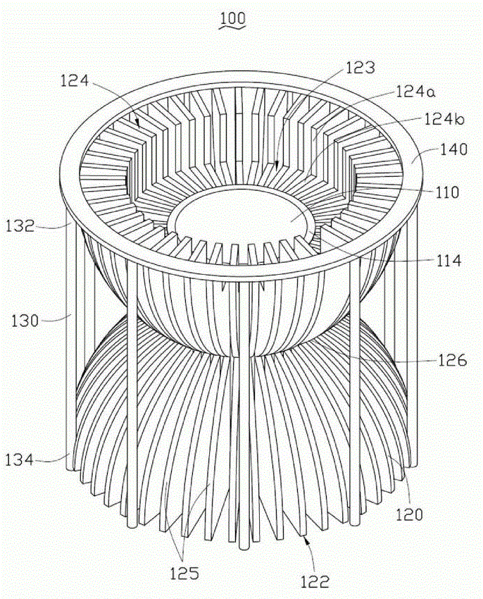
图1是本发明LED灯具散热装置的立体示意图;Fig. 1 is a three-dimensional schematic diagram of a heat dissipation device for an LED lamp of the present invention;
图2是图1中LED灯具散热装置另一角度的立体示意图。FIG. 2 is a schematic perspective view of another angle of the heat sink of the LED lamp in FIG. 1 .
具体实施方式Detailed ways
请参阅图1,本发明较佳实施方式提供的一种LED灯具散热装置100。该LED灯具散热装置100包括一个中心筒110,多个散热鳍片120以及多个热管130。所述多个散热鳍片120以所述中心筒110的轴线为中心呈放射状且间隔均匀的设置在所述中心筒110的外侧。所述多个热管130设置在所述散热鳍片120上。Please refer to FIG. 1 , which shows a
所述中心筒110为一个中空的柱体,其罩设在一个LED光源(图未示)外部。该中心筒110采用耐热且导热材料制成,用以支撑所述LED光源以及将LED光源产生的热量传导至所述散热鳍片120上。所述中心筒110包括一个顶端112以及一个与该顶端112相对的底端114。The
所述多个散热鳍片120由高导热材料如铝、铜、铁等金属制成。其中每一散热鳍片120包括一个第一端122、一个与第一端122相对的第二端124以及一个位于所述第一端122及第二端124之间的中间部126。所述散热鳍片120的第一端122与所述中心筒110的顶端112相互平齐。所述散热鳍片120的第二端124靠近所述中心筒110的轴线的一侧开设有一个缺口124a,该缺口124a的底面124b与所述中心筒110的底端114相平齐,且所述多个散热鳍片120的缺口124a及底面124b一同构成一个容置LED灯具的容置空间123。所述多个散热鳍片120沿垂直于所述中心筒110的轴线的方向的宽度由其第一端122及第二端124向中间部126处逐渐减小,从而使所述多个散热鳍片120形成一个直径由第一端122及第二端124向中间部126逐渐减小的沙漏状散热鳍片组。The plurality of
所述散热鳍片120沿垂直于所述中心筒110的轴线的方向的宽度可以是由其第一端122及第二端124向中间部126线性递减,也可以是由其第一端122及第二端124向中间部126处非线性递减。当所述散热鳍片120沿垂直于所述中心筒110的轴线的方向的宽度由其第一端122及第二端124向中间部126线性递减时,所述第一端122与中间部126及第二端124与中间部126连接的外端面125为倾斜的斜面,该种方式可以方便所述散热鳍片120的制造,同时可增加散热鳍片120上的空气流通空间。当所述散热鳍片120沿垂直于所述中心筒110的轴线的方向的宽度由其第一端122及第二端124向中间部126非线性递减时,例如所述第一端122与中间部126及第二端124与中间部126的外端面125为光滑的曲面,该种方式可保证在散热鳍片120上形成足够的流通空间的同时增加散热鳍片120自身与空气的接触面积,从而加速该散热鳍片120的散热。可以理解地,所述散热鳍片120的第一端122及第二端124向中间部126递减方式也可采用交叉递减的方式,即由第一端122向所述中间部126线性递减或者非线性递减,对应的由所述第二端124向中间部126非线性递减或者线性递减。The width of the heat dissipation fins 120 along the direction perpendicular to the axis of the
所述热管130为一种高效导热装置,其包括一个蒸发端132以及一个冷凝端134。所述蒸发端132固接在所述散热鳍片120的第二端124上,冷凝端134固设在所述散热鳍片120的第一端122。The
使用时,由于所述散热鳍片120采用两端宽中间窄的设计方式,可以使散热鳍片120间空气流动的阻力极大的减小,从而使得散热鳍片120之间的空气流动顺畅,使冷空气快速流经所述散热鳍片120将散热鳍片120上的热量带走。同时,由于散热鳍片120的第二端124与第一端122之间在中间部126的连接区域减少,从而可在第二端124与第一端122之间形成温度差从而形成局部区域的空气对流,使第二端124周围产生的热空气加速上升至第一端122的位置处,在第一端122周围经过冷却的空气又加速流回第二端124,从而加快了散热鳍片120散热效果。此外,由于所述散热鳍片120的第二端124接近LED光源,因此,所述第二端124为热集中区域,因此,设置所述第二端124上的热管130的蒸发端132内部的冷却液(图未示0会在第二端124的热作用下蒸发从而带走第二端124上热量并通过对流将热量带至冷凝端134,由于所述第一端122的温度低于第二端124上的温度,因此,所述蒸发的冷却液在冷凝端134凝结并放出热量,该热量传导至所述散热鳍片120的第一端122并由其将热量散发至空气中,从而可以提高所述LED灯具散热装置100的散热效率。相较现有技术,本发明LED灯具散热装置100通过沙漏状的散热鳍片120来加速散热,并可通过热管130辅助散热,从而极大提高了散热效率,提高LED光源的使用寿命。When in use, since the heat dissipation fins 120 adopt a design with wide ends and a narrow middle, the resistance to air flow between the
为了方便安装所述热管130,可在所述散热鳍片120的第二端124的端面上设置一个固定环140,所述热管130的冷凝端134的端部固定在所述固定环140上。In order to install the
应该指出,上述实施方式仅为本发明的较佳实施方式,本领域技术人员还可在本发明精神内做其它变化。这些依据本发明精神所做的变化,都应包含在本发明所要求保护的范围之内。It should be pointed out that the above embodiments are only preferred embodiments of the present invention, and those skilled in the art can also make other changes within the spirit of the present invention. These changes made according to the spirit of the present invention should be included in the scope of protection of the present invention.
Claims (10)
Priority Applications (2)
| Application Number | Priority Date | Filing Date | Title |
|---|---|---|---|
| CN2009103019564A CN101876427A (en) | 2009-04-29 | 2009-04-29 | LED lamp cooling device |
| US12/635,833 US20100276118A1 (en) | 2009-04-29 | 2009-12-11 | Cooling device for illumination source |
Applications Claiming Priority (1)
| Application Number | Priority Date | Filing Date | Title |
|---|---|---|---|
| CN2009103019564A CN101876427A (en) | 2009-04-29 | 2009-04-29 | LED lamp cooling device |
Publications (1)
| Publication Number | Publication Date |
|---|---|
| CN101876427A true CN101876427A (en) | 2010-11-03 |
Family
ID=43019049
Family Applications (1)
| Application Number | Title | Priority Date | Filing Date |
|---|---|---|---|
| CN2009103019564A Pending CN101876427A (en) | 2009-04-29 | 2009-04-29 | LED lamp cooling device |
Country Status (2)
| Country | Link |
|---|---|
| US (1) | US20100276118A1 (en) |
| CN (1) | CN101876427A (en) |
Cited By (2)
| Publication number | Priority date | Publication date | Assignee | Title |
|---|---|---|---|---|
| CN104654246A (en) * | 2013-11-25 | 2015-05-27 | 苏州承源光电科技有限公司 | LED (light emitting diode) lamp heat dissipater |
| US10088252B2 (en) | 2012-01-20 | 2018-10-02 | Philips Ligting Holding B.V. | Heat transferring arrangement |
Families Citing this family (10)
| Publication number | Priority date | Publication date | Assignee | Title |
|---|---|---|---|---|
| US8567987B2 (en) * | 2009-07-21 | 2013-10-29 | Cooper Technologies Company | Interfacing a light emitting diode (LED) module to a heat sink assembly, a light reflector and electrical circuits |
| US8596837B1 (en) | 2009-07-21 | 2013-12-03 | Cooper Technologies Company | Systems, methods, and devices providing a quick-release mechanism for a modular LED light engine |
| USD662898S1 (en) * | 2011-03-24 | 2012-07-03 | Graftech International Holdings Inc. | Heat sink for LED light bulb |
| TWM497230U (en) * | 2014-10-31 | 2015-03-11 | Kenner Material & System Co Ltd | Solid-state illuminating apparatus having heat dissipating structure with large surface area |
| USD800676S1 (en) * | 2016-08-30 | 2017-10-24 | Abl Ip Holding Llc | Heat sink |
| USD822624S1 (en) * | 2016-08-30 | 2018-07-10 | Abl Ip Holding Llc | Heat sink |
| USD800677S1 (en) * | 2016-08-30 | 2017-10-24 | Abl Ip Holding Llc | Heat sink |
| USD822626S1 (en) | 2016-11-21 | 2018-07-10 | Abl Ip Holding Llc | Heatsink |
| US10415895B2 (en) | 2016-11-21 | 2019-09-17 | Abl Ip Holding Llc | Heatsink |
| CN108637552B (en) * | 2018-07-30 | 2024-07-19 | 中南大学 | Welding heat dissipation device for reinforcing steel bar stress meter |
Family Cites Families (11)
| Publication number | Priority date | Publication date | Assignee | Title |
|---|---|---|---|---|
| US6748656B2 (en) * | 2000-07-21 | 2004-06-15 | Ats Automation Tooling Systems Inc. | Folded-fin heatsink manufacturing method and apparatus |
| US20070253202A1 (en) * | 2006-04-28 | 2007-11-01 | Chaun-Choung Technology Corp. | LED lamp and heat-dissipating structure thereof |
| US7862214B2 (en) * | 2006-10-23 | 2011-01-04 | Cree, Inc. | Lighting devices and methods of installing light engine housings and/or trim elements in lighting device housings |
| TW200934362A (en) * | 2008-01-16 | 2009-08-01 | Neng Tyi Prec Ind Co Ltd | Method of manufacturing heat dissipaters having heat sinks and structure thereof |
| TW200934361A (en) * | 2008-01-16 | 2009-08-01 | Neng Tyi Prec Ind Co Ltd | Method of manufacturing heat dissipater and structure thereof |
| USD591894S1 (en) * | 2008-06-23 | 2009-05-05 | Oleg Lidberg | Housing for LED retrofit fixture |
| CN101614383A (en) * | 2008-06-27 | 2009-12-30 | 富准精密工业(深圳)有限公司 | LED lamp |
| TWM358257U (en) * | 2008-08-03 | 2009-06-01 | Ya-Li Wu | The thermal dissipation structure of steam surface LED lamp |
| CN201336791Y (en) * | 2008-12-17 | 2009-10-28 | 鸿富锦精密工业(深圳)有限公司 | Radiator |
| US20100294462A1 (en) * | 2009-05-19 | 2010-11-25 | Kuo-Len Lin | Heat sink and heat-dissipating fins of the same |
| USD626094S1 (en) * | 2010-03-24 | 2010-10-26 | Journée Lighting, Inc. | Heat sink unit for use with a removable LED light module |
-
2009
- 2009-04-29 CN CN2009103019564A patent/CN101876427A/en active Pending
- 2009-12-11 US US12/635,833 patent/US20100276118A1/en not_active Abandoned
Cited By (3)
| Publication number | Priority date | Publication date | Assignee | Title |
|---|---|---|---|---|
| US10088252B2 (en) | 2012-01-20 | 2018-10-02 | Philips Ligting Holding B.V. | Heat transferring arrangement |
| US10578378B2 (en) | 2012-01-20 | 2020-03-03 | Signify Holding B.V. | Heat transferring arrangement |
| CN104654246A (en) * | 2013-11-25 | 2015-05-27 | 苏州承源光电科技有限公司 | LED (light emitting diode) lamp heat dissipater |
Also Published As
| Publication number | Publication date |
|---|---|
| US20100276118A1 (en) | 2010-11-04 |
Similar Documents
| Publication | Publication Date | Title |
|---|---|---|
| CN101876427A (en) | LED lamp cooling device | |
| CN102130080B (en) | Heat radiation device | |
| CN104132568A (en) | Heat pipe sink for high power density | |
| US20020195230A1 (en) | Heat exchange structure of loop type heat pipe | |
| CN102034773A (en) | Configurational tree-shaped heat pipe radiator | |
| CN101242729A (en) | Capillary microgroove group and thermoelectric combination heat control method and system | |
| TW201038897A (en) | Heat dissipation module and projection apparatus using the same | |
| CN105960147A (en) | Spiral fractal based integrated micro flat plate heat pipe | |
| CN101566748A (en) | Radiating module and backlight module adopting same | |
| CN111664733A (en) | Heat radiator combining micro-channel heat exchanger with heat pipe | |
| CN101281902B (en) | High-power light-emitting diode lighting lamp and heat dissipation module thereof | |
| CN102454969B (en) | LED replaceable universal platform with super heat pipe | |
| WO2019169938A1 (en) | Vehicle lamp and vehicle | |
| TW200835886A (en) | High power LED lighting device and heat dissipation module thereof | |
| CN2763975Y (en) | Heat-pipe radiator | |
| CN102692002A (en) | Heat radiating device of high-power LED (light-emitting diode) | |
| CN101296600A (en) | Heat radiation assembly and electronic device using same | |
| CN107747718A (en) | Automobile lamp radiator structure | |
| CN203615798U (en) | Heat pipe radiator | |
| CN104089505B (en) | Heat pipe radiator | |
| CN205425917U (en) | Superconducting temperature uniform heat sink without structural thermal resistance | |
| CN106402686A (en) | Cooling device of LED array device | |
| CN204014389U (en) | heat pipe radiator | |
| RU123904U1 (en) | LIGHTING DEVICE | |
| CN203202695U (en) | light emitting device |
Legal Events
| Date | Code | Title | Description |
|---|---|---|---|
| C06 | Publication | ||
| PB01 | Publication | ||
| C02 | Deemed withdrawal of patent application after publication (patent law 2001) | ||
| WD01 | Invention patent application deemed withdrawn after publication |
Application publication date: 20101103 |