CN101848805A - Wedge drive with slide receiving device - Google Patents
Wedge drive with slide receiving device Download PDFInfo
- Publication number
- CN101848805A CN101848805A CN200880114991A CN200880114991A CN101848805A CN 101848805 A CN101848805 A CN 101848805A CN 200880114991 A CN200880114991 A CN 200880114991A CN 200880114991 A CN200880114991 A CN 200880114991A CN 101848805 A CN101848805 A CN 101848805A
- Authority
- CN
- China
- Prior art keywords
- slide
- sliding
- wedge
- sliding part
- guide
- Prior art date
- Legal status (The legal status is an assumption and is not a legal conclusion. Google has not performed a legal analysis and makes no representation as to the accuracy of the status listed.)
- Granted
Links
Images


Classifications
-
- B—PERFORMING OPERATIONS; TRANSPORTING
- B30—PRESSES
- B30B—PRESSES IN GENERAL
- B30B1/00—Presses, using a press ram, characterised by the features of the drive therefor, pressure being transmitted directly, or through simple thrust or tension members only, to the press ram or platen
- B30B1/40—Presses, using a press ram, characterised by the features of the drive therefor, pressure being transmitted directly, or through simple thrust or tension members only, to the press ram or platen by wedge means
-
- B—PERFORMING OPERATIONS; TRANSPORTING
- B21—MECHANICAL METAL-WORKING WITHOUT ESSENTIALLY REMOVING MATERIAL; PUNCHING METAL
- B21D—WORKING OR PROCESSING OF SHEET METAL OR METAL TUBES, RODS OR PROFILES WITHOUT ESSENTIALLY REMOVING MATERIAL; PUNCHING METAL
- B21D19/00—Flanging or other edge treatment, e.g. of tubes
- B21D19/08—Flanging or other edge treatment, e.g. of tubes by single or successive action of pressing tools, e.g. vice jaws
- B21D19/082—Flanging or other edge treatment, e.g. of tubes by single or successive action of pressing tools, e.g. vice jaws for making negative angles
- B21D19/084—Flanging or other edge treatment, e.g. of tubes by single or successive action of pressing tools, e.g. vice jaws for making negative angles with linear cams, e.g. aerial cams
Landscapes
- Engineering & Computer Science (AREA)
- Mechanical Engineering (AREA)
- Machine Tool Units (AREA)
- Mounting, Exchange, And Manufacturing Of Dies (AREA)
- Clamps And Clips (AREA)
- Bearings For Parts Moving Linearly (AREA)
- Connection Of Plates (AREA)
- Processing Of Stones Or Stones Resemblance Materials (AREA)
Abstract
Description
技术领域technical field
本发明涉及一种楔驱动器或者销键,该楔驱动器或者销键包括滑动件接收装置、可运动的滑动件和驱动件,其中滑动表面被设置在滑动件和驱动件之间。The invention relates to a wedge driver or key comprising a slide receiver, a movable slide and a drive, wherein a slide surface is arranged between the slide and the drive.
背景技术Background technique
也被称为滑动件的楔驱动器主要用来把挤压力转移到冲压或者成形工具,从而在机体部分的特殊区域内可以进行切割、穿孔或者成形,这些机体部分具有倾斜的或者底切结构。在该布置中,楔驱动器包括至少一个滑动件接收装置、可运动的滑动件和驱动件。具有例如刚性的滑动件接收装置通常被连接到挤压或者压力工具的一部分上,在该压力或者挤压工具中,楔驱动器用来执行冲压或者成形操作。如果其滑动件接收装置被固定在挤压工具的上部中,那么楔驱动器称为上部滑动器,该挤压工具被连接到运动的挤压压头上。如果其滑动件接收装置被连接到固定在刚性挤压工作台上的下部挤压工具上,那么被称为下部滑动器。与楔驱动器的滑动件接收装置连接到其上的部分无关,它通常具有线性导向装置,在该线性导向装置中,可运动的滑动件可以进行往复运动,但是同样地,它被牢固地连接到滑动件接收装置上。驱动件通常呈刚性件的形式,该刚性件牢固地连接到挤压工具的该部分上,而滑动件接收装置没有固定到该部分上。驱动件通常具有倾斜的楔部分并且于是用作可运动的滑动件的驱动件。Wedge drives, also known as slides, are mainly used to transfer the pressing force to punching or forming tools so that cutting, perforating or forming can be carried out in specific areas of body parts with inclined or undercut structures. In this arrangement, the wedge drive comprises at least one slide receiver, a movable slide and a drive. A slide receiver, eg rigid, is usually attached to a part of a pressing or pressing tool in which a wedge driver is used to perform a punching or forming operation. The wedge drive is referred to as an upper slide if its slide receiver is fixed in the upper part of the pressing tool, which is connected to the moving pressing ram. If its slide receiver is attached to a lower extrusion tool fixed on a rigid extrusion table, it is called a lower slide. Regardless of the part of the wedge drive to which the slide receiver is attached, it usually has a linear guide in which the movable slide can reciprocate, but again it is firmly attached to the on the slider receiver. The driver is usually in the form of a rigid member which is firmly connected to the part of the extrusion tool to which the slide receiver is not fixed. The drive usually has an inclined wedge section and thus serves as a drive for the movable slide.
在包括挤压工具进行实质上垂直向前运动(这称为工作冲程)的情况下,处于它后部位置上的滑动件支靠着刚性直立的驱动件并且被支撑,因此借助面向工作方向的其倾斜定位(楔形)来使之前进。在该情况下,滑动件接收装置的线性导向装置的倾斜度与驱动件的倾斜定位相匹配,因此相对于实际挤压速度,所涉及的可运动的滑动件没有加速。因此,借助挤压工具只驱动可运动的滑动件,并且可控制地向前或者向外推动该滑动件,从而可以执行冲压或者成形工作。在挤压工具运动到它的下死点位置之外并且两个部分彼此又移离的向后冲程运动中,可运动的滑动件借助合适设计的弹性件而通常被推回到它的原始位置上,因此该过程可以重新开始。滑动件的返回运动所需要的返回力通常为实际工作力和滑动件的重量的2%到10%。在该方面,挤压力大小的决定方面是用来传递该压力的表面的尺寸、滑动件接收装置中的线性导向装置的各个倾斜度和驱动件的倾斜定位及这些表面和倾斜度的配合和滑动件本身的结构,这些表面称为滑动表面。要被传递的压力通常为几个100KN到许多10,000KN。In the case of a substantially vertical forward movement involving the extrusion tool (this is called the working stroke), the slide in its rear position rests against the rigid upright drive and is supported so that it is It is positioned obliquely (wedge-shaped) to advance the front. In this case, the inclination of the linear guide of the slide receiver is adapted to the inclined positioning of the drive, so that the movable slide involved is not accelerated relative to the actual extrusion speed. Thus, only the movable slide is driven by means of the pressing tool and is pushed forward or outward in a controlled manner so that punching or forming work can be carried out. During the backward stroke movement in which the pressing tool moves beyond its bottom dead center position and the two parts move away from each other again, the movable slide is usually pushed back to its original position by means of a suitably designed elastic on, so the process can start over. The return force required for the return movement of the slider is typically 2% to 10% of the actual working force and the weight of the slider. In this respect, the determining aspects of the magnitude of the pressing force are the dimensions of the surfaces used to transmit this pressure, the respective inclinations of the linear guides in the slide receiver and the oblique positioning of the drive and the fit and fit of these surfaces and inclinations. The structure of the sliding part itself, these surfaces are called sliding surfaces. The pressure to be delivered is typically a few 100KN to many 10,000KN.
滑动件接收装置中的线性导向装置用来尽可能没有间隙地引导可运动的滑动件并且在这样做时承受较大的挤压力,以及提供了较长的使用寿命。为了使工件可以进行没有毛口的切割或者穿孔,因此需要最大为0.02mm的可运动的滑动件的运动精确度的公差。如果该公差得不到满足,那么以一些其它方式被切割、穿孔或者成形的工件不再可以以精确对准的关系一个放置在另一个上,因此产生了基本机体结构中的错误和/或工件彼此靠着摩擦意味着产生了更快的侵蚀,所构造的机体的强度减小了,并且由于金属片零件变松而可能产生了增大的噪声量。为了避免所有这些缺点,尤其在汽车工业中的要求是,楔驱动器具有极其高的运动精确度并且永久地承受所需要的挤压压力或者相对于冲压或者成形工具使它们有用。The linear guide in the slide receiver serves to guide the movable slide with as little play as possible and in doing so absorbs high pressing forces and provides a long service life. In order for workpieces to be cut or perforated without burrs, a tolerance of the movement accuracy of the movable slide of a maximum of 0.02 mm is therefore required. If this tolerance is not met, workpieces that are cut, perforated, or shaped in some other way can no longer be placed one on top of the other in precisely aligned relationship, thus creating errors in the basic body structure and/or workpieces Rubbing against each other means faster erosion, less strength in the constructed body and possibly increased noise levels due to loosening of the sheet metal parts. In order to avoid all these disadvantages, it is required, especially in the automotive industry, that the wedge drives have extremely high movement precision and permanently withstand the required pressing pressure or make them useful in relation to stamping or forming tools.
为了提供所需要的运动精确度,因此产生了各种各样的构思,其中一些在下文中将提出。作为例子,已知具有侧滑动板的滑动件导向装置和以直角布置的驱动件以及用来保持滑动件的螺旋罩板。那种滑动件导向装置诚然可以承受非常高的挤压力和横向推力,但是它们非常复杂并且制造费用很高,因为需要高程度的手动协调复杂性和费用来匹配位于这些元件之间的导向间隙。已发现的其它问题是不足够地防止滑动件导向装置下降分开,在这种情况下,滑动件重量加上向后的连接力之和作用在罩板的固定螺钉上并且可以非常快速地使它们超载。此外,这种滑动件导向装置的结构尺寸相对较大,并且因此该导向装置不适合于构造小型的滑动件。In order to provide the required motion precision, various concepts have therefore been developed, some of which are presented below. As an example, slide guides with side slide plates and drives arranged at right angles as well as screw caps for holding the slide are known. Slider guides of that kind can certainly withstand very high crushing and lateral thrusts, but they are very complex and expensive to manufacture due to the high degree of manual coordination complexity and expense required to match the guide gaps located between these elements . Other problems that have been found are insufficient prevention of the slide guides from falling apart, in which case the sum of the slide weight plus the rearward coupling force acts on the set screws of the fascia and can dislodge them very quickly. overload. Furthermore, such a slide guide has relatively large structural dimensions and is therefore not suitable for the construction of small slides.
滑动件导向装置还公知为,具有横向角铁,和以直角来布置的驱动板。与上述滑动件导向装置不同,横向滑动板和罩板的结合导致所需要的结构空间的大小减小,因此尤其地,作为结果而构造更小的滑动器尺寸也是可能的。但是将注意到,较大的力作用在角铁的固定螺钉上,并且结果是提供了,具有相对较高的事故危险。此外,协调配合元件以匹配该导向间隙的复杂性和费用较高,因此在这里也导致了额外的费用。Slide guides are also known with transverse angle irons and drive plates arranged at right angles. In contrast to the above-described slide guides, the combination of the transverse slide plate and the cover plate leads to a reduction in the size of the required installation space, so that in particular smaller slider dimensions are also possible as a result. It will be noted, however, that relatively high forces act on the fixing screws of the angle iron and that, as a result, there is a relatively high risk of accidents. Furthermore, the complexity and complexity of adjusting the mating element to this guide gap is high, so additional costs are also incurred here.
所使用的其它种类的滑动件导向器包括横向滑动和罩板,该板以45°的角度倾斜。因此它们大致布置在屋顶形结构中。这使得下面是可能的,即减小了结构宽度,因为罩棒和滑动板一个布置在另一个上,而不是一个位于另一个的旁边。但是,注意到,所需要的结构空间仍然非常大,因此几乎不可能形成较小的滑动件。此外,所产生的牵引力对罩板的固定螺钉具有有害的影响,并且导致了高程度的处理不确定性。Other types of slide guides used include lateral slides and cover plates which are inclined at an angle of 45°. They are therefore arranged approximately in a roof-shaped structure. This makes it possible to reduce the structural width, since the cover bar and the sliding plate are arranged one above the other instead of one next to the other. Note, however, that the required construction space is still very large, so that it is almost impossible to form smaller slides. Furthermore, the generated traction forces have a detrimental effect on the fixing screws of the fascia and lead to a high degree of handling uncertainty.
其它已知的结构包括具有驱动板的滑动件导向装置和具有衬套的一个或者两个柱导向装置,从而横向地保持住滑动件并且防止它掉出。具有驱动板的导向柱的使用意味着,无可否认地只需要仍然相对较小的结构空间,并且在现有技术中使用上述技术方案时,实现明显较少费用的制造是可能的。但是,将注意到,柱导向装置由于所包括的结构的类型而不能补偿较高的横向压力。此外,它不能承载任何特别重的滑动件,因此这些滑动件产生了较小的挤压力并且更加容易受挤压过程中的麻烦的影响。Other known structures include a slider guide with a drive plate and one or two post guides with bushings to hold the slider laterally and prevent it from falling out. The use of the guide column with the drive plate means that, of course, only a still relatively small installation space is required, and a considerably less expensive production is possible in the prior art with the above-mentioned solution. It will be noted, however, that the column guide cannot compensate for higher lateral pressures due to the type of structure involved. Also, it can't carry any particularly heavy slides, so those slides create less crushing force and are more susceptible to troubles in the crushing process.
例如EP 1 035 965 61公开了另一种滑动件导向布置。该布置提供了关于滑动件导向装置的夹紧包围关系,其中驱动件提供了棱柱导向件,及滑动板被插入到驱动件和滑动件之间。所包括的屋顶形意味着,非常高的滑动件作用力是可能的,同时产生了较小的结构空间,及同样地产生了非常精确的导向间隙,因此楔驱动器或者滑动件导向装置是稳定的,并且具有较长的工作寿命。但是,将注意到,夹紧导向装置的制造由于需要昂贵的切割机械工作来获得精确的安装形状而实际上被复杂化且作为结果是费用高的。For
例如EP 1259371B1、DE 198 60 178 C1和EP 1 197 319 B1也公开了其它的楔驱动器。For example EP 1259371B1, DE 198 60 178 C1 and
楔驱动器的滑动件导向装置的所有上述设计原理具有一个或者多个滑动板来传递总体上较大的挤压力,并且同样地,合适地设计的保持件用于把滑动件保持在为上述的所设置的导向件中。该滑动板用来永久地把由挤压工具所施加的工作压力从滑动件接收装置和驱动件传递到可运动的滑动件并且因此保证实际前进的驱动效果。保持件用来线性地把滑动件保持在滑动件接收装置的滑动板上,在这种情况下,它们永久地确保所需要的运动精确度,并且旨在可能补偿横向推力,而该横向推力产生于成形操作或者切割或者冲压过程中。All the above-mentioned design principles of the slide guides of the wedge drive have one or more slide plates to transmit the generally large pressing force, and likewise a suitably designed retainer for holding the slide in the above-mentioned position. in the set guides. The slide plate serves to permanently transmit the working pressure exerted by the pressing tool from the slide receiver and the drive part to the movable slide and thus ensures the actual forward drive effect. The holders are used to linearly hold the slide on the slide plate of the slide receiver, in which case they permanently ensure the required precision of movement and are intended to possibly compensate for lateral thrusts which generate During forming operations or during cutting or punching.
发明内容Contents of the invention
现在,本发明的目的是以这样的方式进一步研发一种如权利要求1的分类部分中所提出的楔驱动器,以致提供了一种可运动的滑动件的导向件,与现有技术中的技术方案相比,该导向件允许具有更好的运动精确度,它可以最佳地转化挤压力,该挤压力作用到冲压或者成形运动中,与现有技术相比,这更好地补偿了横向推力,并且与现有技术的技术方案的可能性相比,为楔驱动器提供了更长的使用寿命。本发明还寻求提供,在协调楔驱动器和更经济的制造变成可能时,需要使复杂程度和费用降低。Now, the object of the present invention is to further develop a wedge drive as proposed in the classification part of
对于权利要求1的分类部分中所提出的楔驱动器,达到了这个目的,由于楔形榫状(dovetail-like)或者棱柱导向装置被设置在滑动件和滑动件接收装置之间。对于这种楔驱动器的滑动件,达到了本发明的目的,由于滑动件具有楔形榫状或者棱柱形侧部。本发明的其他改进在从属权利要求中被限定出。For a wedge drive as set forth in the classification part of
因此提供了一种楔驱动器或者销键,在该驱动器或者销键中,可运动的滑动件具有楔形榫状或者棱柱侧部,其中滑动件接收装置处于对应相配部分的形式,因此具有楔形榫状或者棱柱侧部的滑动件可以接合到滑动件接收装置内并且可以被导向及被保持于其中。分别由楔形榫形状和棱柱形状来提供的滑动件和/或滑动件接收装置上的表面彼此支靠,在这种情况下,依靠楔形榫或者棱柱形状中的该表面没有任何问题地可以承载指向不同方向的力,而该表面相对于彼此成一角度。楔形榫形状意味着,在被插入到滑动件接收装置的、对应成形的接收结构内之后,在没有其他措施的情况下,可防止可运动的滑动件掉出或者横向移动。There is thus provided a wedge drive or pin in which the movable slide has a dovetail or prismatic side, wherein the slide receiver is in the form of a corresponding counterpart and thus has a dovetail Or the slides of the sides of the prism can engage into the slide receptacle and can be guided and held therein. The surfaces on the slide and/or the slide receiver provided by the dovetail shape and the prism shape respectively bear against each other, in which case the surfaces in the dovetail or prism shape can bear the load pointing without any problem. Forces in different directions while the surfaces are at an angle relative to each other. The dovetail shape means that, after being inserted into a correspondingly shaped receiving structure of the slide receptacle, the movable slide is prevented from falling out or moving laterally without further measures.
有利的是,滑动表面被设置在滑动件和/或滑动件接收装置上。在特别优选的特征中,楔形榫状或者棱柱导向装置包括至少两个滑动板,而这两个滑动板被布置成相对于彼此成一角度。有利的是,楔形榫状或者棱柱导向装置的滑动板的横截面可以是L形横截面。如果滑动板被设置在滑动件和滑动件接收装置的所有表面上,那么被进一步发现是有利的,该表面彼此靠着滑动,因此在每种情况下,相对于彼此以一角度布置的至少两个滑动板被设置在滑动件和滑动件接收装置上。横截面是屋顶形或者L形的滑动板可以被有利地布置成,它们的内部窄的侧部由于滑动板向外倾斜的倾斜定位而提供了处于上述楔形榫导向结构形式的底切结构。Advantageously, the sliding surface is provided on the slide and/or on the slide receiver. In a particularly preferred feature, the dovetail or prismatic guide comprises at least two sliding plates arranged at an angle relative to each other. Advantageously, the cross-section of the sliding plate of the dovetail-like or prismatic guide can be an L-shaped cross-section. It was further found to be advantageous if sliding plates are arranged on all surfaces of the slider and of the slider receiving means, which surfaces slide against each other, so that in each case at least two parts arranged at an angle relative to each other A slide plate is provided on the slide and the slide receiver. Sliding plates that are roof-shaped or L-shaped in cross-section can advantageously be arranged such that their inner narrow sides provide an undercut in the form of the dovetail guides described above due to the outwardly slanted positioning of the sliding plates.
由于在滑动件和滑动件接收装置的两侧部上分别同时提供了滑动板,其中它们被对称地布置并且处于L形或者处于屋顶形,因此可以获得楔形榫导向装置的形状,因此无需其它的、费用高的线性保持件是特别有利、可能的。此外,与现有技术的技术方案相比,可以明显地减少制造费用,因为与现有技术相比,在没有以任何方式不利地影响楔驱动器的工作模式的情况下,所设置的部件较少,但是在没有提供保持件的情况下允许更加可靠地和更加安全地工作,而具有极高的运动精确度。Due to the simultaneous provision of sliding plates on both sides of the slider and the slider receiver respectively, wherein they are arranged symmetrically and in an L-shape or in a roof-shape, the shape of the dovetail guide can be obtained so that no other A cost-intensive linear holder is particularly advantageous and possible. Furthermore, the production costs can be significantly reduced compared to prior art solutions, since fewer components are provided than in the prior art without in any way adversely affecting the mode of operation of the wedge drive , but allows a more reliable and safer work without providing a holder, with a very high degree of movement accuracy.
有利的是,楔形榫状或者棱柱导向装置包括位于滑动件和滑动件接收装置之间的有效锁紧(positively locking)连接部。这种有效锁紧连接部的设置提供了紧凑的单元,借助该单元,甚至可以没有任何问题地传递较高的挤压力。此外,由于在楔形榫或者棱柱导向装置的区域中和在要被接合的滑动件和滑动件接收装置的两个部分之间的机械接触部内的有效锁紧关系提供了要被传递的力事实上借助彼此接触的表面来传递,它可以防止滑动件和滑动件接收装置不希望地彼此滑出来,该表面相对于彼此成一角度,及在该方面中,依靠它们的角度定位有助于把部件保持在一起。Advantageously, the dovetail or prismatic guide comprises a positively locking connection between the slider and the slider receiver. The provision of such an active locking connection provides a compact unit by means of which even high pressing forces can be transmitted without any problems. Furthermore, due to the effective locking relationship in the area of the dovetail or prismatic guide and in the mechanical contact between the two parts of the slider to be engaged and the slider receiver, the force to be transmitted is virtually It prevents the slide and the slide-receiving means from sliding out of each other undesirably by means of surfaces in contact with each other, which surfaces are at an angle relative to each other, and in this respect, by virtue of their angular positioning helps to hold the parts together.
如果滑动件接收装置在滑动板的滑动表面和/或滑动板的接收装置的区域中具有突出结构,那么进一步被证明是有利的。相对于滑动件接收装置,这为滑动件的滑动提供了更大的表面,因此借助这些扩大的接收表面,可以使挤压力得到非常好的传递。It has furthermore proven to be advantageous if the slider receptacle has a protruding structure in the region of the sliding surface of the slide plate and/or of the receptacle of the slide plate. This provides a larger surface for the slide to slide relative to the slide receiver, so that the pressing force can be transmitted very well by means of these enlarged receiving surfaces.
有利的是,滑动板可以被可松开地固定到滑动件接收装置和/或滑动件上,尤其是借助固定螺钉来被固定到滑动件接收装置和/或滑动件上。滑动板分别从滑动件接收装置和滑动件松开意味着,在产生了磨损时可以更换它们。应该知道,以这样的方式来配置滑动件接收装置和滑动件的相应滑动表面原则上也是可能的,即在没有插入滑动板的情况下,它们可以彼此靠着滑动。但是,在如果发生磨损的情况下,需要更换滑动件接收装置和滑动件它们本身,因此这被证明费用便宜并且就处理而言操作简单,如果该布置具有可松开的滑动板,那么其更换可以是快速的并且没有任何困难。Advantageously, the slide plate can be fastened releasably to the slide receptacle and/or the slide, in particular by means of fixing screws to the slide receptacle and/or the slide. The release of the slide plate from the slide receiver and the slide, respectively, means that they can be replaced when wear occurs. It should be appreciated that it is also possible in principle to configure the slider receiving means and the corresponding sliding surfaces of the slider in such a way that they can slide against each other without an interposed sliding plate. However, this proves to be inexpensive and simple in terms of handling, in the event of wear, the slide receiver and the slides themselves needing to be replaced, and if the arrangement has releasable slide plates, then its replacement Can be fast and without any difficulty.
有利的是,具有楔形榫状或者棱柱形状的滑动件的侧部具有支撑表面作为滑动表面,尤其用于滑动板的连接。在每种情况下设置两个滑动板,被证明是尤其有利的,而这两个滑动板被布置成相对于彼此成一角度,因为在这里可以避免费劲地调整四个单独的滑动板,而该滑动板被布置成相对于彼此成一角度。对于各个滑动板只需要在各自一个支撑表面上进行调整,从而可以快速地改变滑动板。It is advantageous if the sides of the slide with dovetail or prismatic shape have support surfaces as sliding surfaces, in particular for the connection of slide plates. It has proven to be particularly advantageous to provide two slide plates in each case, which are arranged at an angle relative to each other, since here it is possible to avoid laborious adjustment of four separate slide plates, which The sliding plates are arranged at an angle relative to each other. Only adjustments need to be made on the respective support surface for each sliding plate, so that the sliding plate can be changed quickly.
有利的是,楔导向装置被设置在滑动件和驱动件之间。这种布置提供了,可以承载非常大的力,然而具有相对较小的结构空间,同时在运动时可以为驱动件上的滑动件进行精确、稳定的引导。Advantageously, the wedge guide is arranged between the slide and the drive. This arrangement makes it possible to accommodate very high forces while having a relatively small installation space and at the same time to provide a precise and stable guidance of the sliding part on the drive part during the movement.
有利的是,楔导向装置包括两个滑动板,这两个滑动板被布置成相对于彼此成一角度。有利的是,这些滑动板包括这样的材料,即该材料有助于滑动,尤其是具有固态润滑剂的青铜。尤其可更换地被固定到驱动器和/或滑动件上的滑动板的设置是以一种简单的方式来提供的,即在磨损的情况下该板可以被更换,同时在工作时提供了驱动件和滑动件表面的最佳滑动,而该表面彼此接合。Advantageously, the wedge guide comprises two sliding plates arranged at an angle relative to each other. Advantageously, these sliding plates comprise a material that facilitates sliding, especially bronze with a solid lubricant. The arrangement of the sliding plate, which is especially exchangeably fixed to the drive and/or the slide, is provided in a simple manner that the plate can be replaced in the event of wear, while providing the drive during operation. and optimal sliding of the slide surfaces that engage each other.
还证明有利的是,如果楔形榫状或者棱柱导向装置和楔导向装置被设置成在滑动件上相对于彼此成一角度。相对于彼此有多个角度的这种布置意味着,尤其可以减小楔驱动器的结构尺寸大小,因此提供了紧凑的单元,甚至可以在挤压工具内的受限空间条件下来使用该单元。It has also proven to be advantageous if the dovetail or prismatic guide and the wedge guide are arranged on the slide at an angle relative to each other. Such an arrangement at multiple angles relative to each other means that, in particular, the structural dimensions of the wedge drive can be reduced, thus providing a compact unit which can be used even in confined space conditions within the pressing tool.
还发现有利的是,如果楔形榫状或者棱柱导向装置和楔导向装置被设置在滑动件的两个彼此邻近侧处。这使得可以提高运动精确度,但同时主要地,与现有技术的技术方案相比,可以减小结构尺寸大小,而该现有技术的技术方案通常包括在驱动件上的可操作的接合和在滑动件接收装置上的可操作的接合,其位于滑动件的两个彼此相对地布置的侧部处。It has also been found to be advantageous if the dovetail-like or prismatic guide and the wedge guide are provided at two mutually adjacent sides of the slide. This makes it possible to increase the precision of movement, but at the same time, mainly, to reduce the size of the structure compared with the technical solutions of the prior art, which usually consist of operative joints and joints on the drive. An operable engagement on the slider receiver at two sides of the slider which are arranged opposite to each other.
滑动件可以具有邻近其他两侧的第三侧,该第三侧具有用于接收加工工具的接收装置。在该情况下,有利的是,第三侧具有至少两个底切结构和/或凹槽,该底切结构和/或凹槽用来插入用于接收加工工具的接收装置的突出件。设置用来接收加工工具如穿孔冲压机的这种单独的接收装置可以使得,没有任何困难地、简单地更换该工具,因为只需要从滑动件的第三侧中拆下该接收装置,并且用例如装载不同工具的另一个接收装置来更换。可以通过在滑动件中钻出其他孔,这完全消除了拧上和拧下加工工具本身的令人烦恼过程。在滑动件的第三侧处设置底切结构和/或凹槽意味着,接收装置可以被插入到那里,例如,被推入到合适位置上,在该情况下,甚至不需要其他固定,因为力的最佳传递已经得到保证,尤其是利用底切结构,因为提供了有效锁紧连接。The slide may have a third side adjacent the other two sides, the third side having receiving means for receiving a working tool. In this case, it is advantageous if the third side has at least two undercuts and/or grooves for inserting protrusions of a receiving device for receiving a processing tool. This separate receiving device which is provided for receiving a processing tool such as a piercing punch makes it possible to simply replace the tool without any difficulty, because only the receiving device needs to be removed from the third side of the slide and used For example another receiving device loaded with a different tool is exchanged. Additional holes can be drilled in the slide, which completely eliminates the annoying process of screwing on and off the machining tool itself. The provision of undercuts and/or grooves at the third side of the slide means that the receiving device can be inserted there, for example, pushed into place, in which case no further fixing is even required, because An optimal transmission of forces is already guaranteed, especially with the undercut construction, since an effective locking connection is provided.
滑动件的第三侧也可以设置有至少一个楔表面,在该情况下,接收装置于是优选地具有相应楔表面,以在滑动件和加工工具的接收装置之间提供有效锁紧连接。因此可以承载横向推力,并且可以使力的传递最佳化。The third side of the slide can also be provided with at least one wedge surface, in which case the receiving means then preferably has a corresponding wedge surface in order to provide an effective locking connection between the slide and the receiving means of the processing tool. Lateral thrusts can thus be accommodated and the transmission of forces can be optimized.
楔驱动器的工作模式通常包括工作冲程和返回运动。在工作冲程期间,滑动件在驱动件和滑动件接收装置的滑动表面之间被向外移动,该滑动表面被布置成楔形形式,在该情况下,滑动件接收装置和驱动件可以向着彼此垂直地运动,由挤压冲程来驱动。在该方面,由挤压工具所施加的挤压力与反作用力相对应,楔驱动器施加该反作用力来通过其做工作如切割、穿孔或者后成形机体部分,其中根据单个滑动表面相对于彼此的各个角度位置,其被分配到滑动表面上。由于设置了滑动表面,而该滑动表面被布置成相对于彼此成一角度并且该滑动表面被布置相对于彼此处于屋顶形状或者棱柱形状,因此可运动的滑动件在滑动件接收装置和驱动件之间或者在其滑动表面上自动地被对中。这可以为滑动件提供非常高的运动精确度和横向导向,同时由制造所产生的制造公差或者其它错误可以得到补偿,并且因此不再具有不利的影响。The working mode of wedge drive usually includes working stroke and return movement. During the working stroke, the slide is moved outwards between the sliding surfaces of the driver and the slide receiver, which slide surfaces are arranged in a wedge-shaped form, in which case the slide receiver and the drive can be perpendicular to each other Earth movement, driven by extrusion stroke. In this respect, the pressing force exerted by the pressing tool corresponds to the reaction force exerted by the wedge drive to do work therethrough such as cutting, piercing or post-forming body parts, wherein according to the relative position of the individual sliding surfaces relative to each other Each angular position, which is assigned to the sliding surface. Due to the provision of sliding surfaces which are arranged at an angle relative to each other and which are arranged in a roof shape or prism shape relative to each other, the movable slider is between the slider receiving means and the drive Or be centered automatically on its sliding surface. This makes it possible to provide the slide with very high movement precision and lateral guidance, while manufacturing tolerances or other errors resulting from manufacturing can be compensated for and thus no longer have adverse effects.
在滑动件的返回运动、称为向后冲程中,其中挤压工具彼此移离,并且因此滑动件接收装置被移离驱动件,滑动件被缩回到位于滑动件接收装置和驱动件之间的区域内。位于滑动件接收装置和滑动件之间的导向装置的楔形榫形状又允许滑动件的自对中线性导向。当挤压工具移开时,只借助滑动件的重量和作用在滑动件接收装置、滑动件和驱动件上的缩回力来限制在向后冲程中或者在返回运动中作用在滑动件上的该力。During the return movement of the slide, called the backward stroke, in which the pressing tools are moved away from each other and thus the slide receiver is moved away from the drive, the slide is retracted to be located between the slide receiver and the drive within the area. The dovetail shape of the guide between the slide receiver and the slide in turn allows a self-centering linear guidance of the slide. When the pressing tool is moved away, only the weight of the slide and the retraction force acting on the slide receiver, slide and driver are limited to the force acting on the slide in the backward stroke or in the return movement. force.
相对于在工作冲程中彼此靠着行进的滑动表面,在该情况下彼此靠着行进的、滑动件和滑动导向件的滑动表面的尺寸可以被减小,因此在该方面发现上述L形状对于楔形榫导向装置上的滑动表面来说是非常适合的。The size of the sliding surfaces of the slide and slide guide running against each other in this case can be reduced relative to the sliding surfaces running against each other during the working stroke, so in this respect it is found that the above-mentioned L-shape is more important than the wedge-shaped Ideal for sliding surfaces on tenon guides.
在上部分滑动件或者楔驱动器被悬挂的情况下,滑动件的重量作用在滑动件接收装置的表面上,而该表面以有效锁紧关系支靠着楔形榫导向布置的滑动件滑动表面,并且把向下指向的分散力(spreading force)施加在滑动件接收装置的那些表面上。但是,由于滑动件相对于滑动件接收装置的有效锁紧台肩支撑,那些横向推力被补偿,因此可以把滑动件永久地并且稳定地固定到滑动件接收装置上和位于滑动件和滑动件接收装置上的滑动板上。因此滑动板的固定螺钉不承受例如损坏它的任何力,尤其是不承受张力。在没有提供处于线性导向装置形状的其它部件的情况下,借助楔形榫导向装置可以实现滑动件沿着滑动件接收装置的导向,以及高度的精确度和对横向推力不敏感并且制造费用便宜,其结果是,具有非常高水平的运动精确度的紧凑的楔驱动器,该楔驱动器也对制造公差不敏感。由于不再需要夹紧导向件或者其它元件,与现有技术的技术方案相比,不仅可以减少费用,而且该过程的可靠性也得到提高并且降低了可能的事故危险。由于滑动件只需要被推动到滑动件接收装置内,与现有技术的技术方案相比,楔驱动器的组件被简化。省去导向件中的费用贵的研磨操作是可能的,因为滑动件接收装置、滑动件和驱动件的棱柱导向件或者楔形榫导向件对制造公差不敏感。由棱柱导向件所达到的自对中效果关于承载横向推力也产生了非常高的运动精确度。由于楔驱动器的结构紧凑,因此它不仅适合于在挤压工具内所得到的小型结构空间,而且如会知道的那样,它也适合于包括较大尺寸在内的用途。设置在滑动件和滑动件接收装置之间的棱柱导向装置或者楔形榫状导向装置因此可以被用来装备小型、中型和大型的楔驱动器,因此提供了较大的使用范围。在下文中参照附图来更加详细地描述示例性的实施例,以更加完全地描述本发明。With the upper part slide or wedge drive suspended, the weight of the slide acts on the surface of the slide receiver which bears in effective locking relation against the slide slide surface of the dovetail guide arrangement, and A downwardly directed spreading force is applied to those surfaces of the slider receiver. However, due to the effective locking shoulder support of the slide relative to the slide receiver, those lateral thrusts are compensated, thereby permanently and stably fixing the slide to the slide receiver and between the slide and the slide receiver. slide plate on the unit. The fastening screw of the sliding plate is therefore not subjected to any forces, in particular not tension, which would damage it, for example. With the aid of dovetail guides, the guidance of the slide along the slide receiver can be achieved without providing additional components in the shape of a linear guide, with a high degree of precision and insensitivity to lateral thrusts and cheap manufacturing, which The result is a compact wedge drive with a very high level of motion precision, which is also insensitive to manufacturing tolerances. Since clamping guides or other elements are no longer required, not only can the costs be reduced compared to prior art solutions, but the reliability of the process is also increased and the possible risk of accidents is reduced. The assembly of the wedge drive is simplified compared to prior art solutions, since the slider only has to be pushed into the slider receiver. It is possible to dispense with an expensive grinding operation in the guide, since the slide receiver, the prismatic guide or the dovetail guide of the slide and drive are not sensitive to manufacturing tolerances. The self-centering effect achieved by the prismatic guides also produces a very high precision of movement with regard to carrying lateral thrusts. Due to the compact design of the wedge drive, it is not only suitable for the small installation space obtained in the extrusion tool, but also, as will be known, for applications including larger dimensions. Prismatic guides or dovetail guides arranged between slide and slide receptacle can thus be used to equip small, medium and large wedge drives, thus providing a greater range of use. Exemplary embodiments are described in more detail hereinafter with reference to the accompanying drawings in order to more fully describe the present invention.
附图说明Description of drawings
图1示出了通过具有楔形榫状导向装置的、根据本发明的楔驱动器的第一实施例的竖直横剖视图;1 shows a vertical cross-sectional view through a first embodiment of a wedge drive according to the invention with a dovetail-like guide;
图2示出了图1的楔驱动器的滑动件接收装置和滑动件的透视图;Figure 2 shows a perspective view of the slider receiver and the slider of the wedge drive of Figure 1;
图3示出了图2的滑动件接收装置和滑动件的透视分解图;Figure 3 shows a perspective exploded view of the slider receiver and slider of Figure 2;
图4示出了楔形榫状导向装置位于滑动件和滑动件接收装置之间的、根据本发明的楔驱动器的第二实施例的透视图;Figure 4 shows a perspective view of a second embodiment of a wedge drive according to the invention with a dovetail-like guide located between the slide and the slide receiver;
图5示出了没有驱动件的图4的楔驱动器的透视图;Figure 5 shows a perspective view of the wedge driver of Figure 4 without the drive;
图6示出了图4的楔驱动器的透视侧视图;Figure 6 shows a perspective side view of the wedge driver of Figure 4;
图7示出了图4的楔驱动器的横向平面视图;Figure 7 shows a transverse plan view of the wedge driver of Figure 4;
图8示出了图4的楔驱动器的剖面侧视图;Figure 8 shows a cutaway side view of the wedge driver of Figure 4;
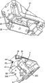
图9示出了从图4所示的、具有安装的加工工具的接收装置的楔驱动器的上方倾斜地看去的透视图;FIG. 9 shows a perspective view obliquely from above of the wedge drive shown in FIG. 4 with the receiving device of the processing tool installed;
图10示出了在驱动件被拆下的情况下设置有图9所示的加工工具的接收装置的楔驱动器的透视图;及Figure 10 shows a perspective view of the wedge driver provided with the receiving means for the processing tool shown in Figure 9 with the driver removed; and
图11示出了在加工工具的接收装置被拆下和驱动件被拆下的情况下图10的楔驱动器的透视图。FIG. 11 shows a perspective view of the wedge drive of FIG. 10 with the receptacle of the processing tool removed and the driver removed.
具体实施方式Detailed ways
图1示出了楔驱动器1或者销键(cotter key)的剖视图,该楔驱动器或者销键包括滑动件接收装置2、滑动件3和接收加工工具的接收装置4。连接到滑动件3上的驱动件在图1中不能看到,但是在图4的透视图中可以发现。Figure 1 shows a cross-sectional view of a
滑动件和滑动件接收装置借助楔形榫状或者棱柱导向装置6来连接在一起。在这种情况下,滑动件3具有楔形榫状结构的一部分30。它包括两个滑动表面31、32、33、34,这两个表面相互以一定角度分别设置在两侧上。在该布置中,两个滑动表面31和33小于两个滑动表面32和34。其原因在于,在工作冲程中,挤压工具所施加的挤压力借助滑动表面32、34从滑动器接收装置传递到滑动件,在该挤压工具中,布置了楔驱动器。在挤压工具的返回运动或者向后冲程(strake)运动中,滑动件借助两个滑动表面31、33缩回,在这种情况下,在滑动件上施加一个小得多的力,因此对于该滑动表面的这些较小的尺寸大小就足够了。The slide and slide receiver are connected together by means of dovetail or
滑动件接收装置2具有部分20,该部分20具有相应相对的和相同的结构,并且包括相应的滑动表面21至24,这些表面中的每一个以有效锁紧的关系靠着滑动表面31至34。此外,在滑动件接收装置2中,楔形榫状结构的该部分30以有效锁紧关系通过突出部35接合到相应凹进部25中。突出部35可以仅分别在滑动件的纵向延伸部的一部分上和滑动件接收装置上延伸。The
原则上,不设置这样的突出部也是可以的,但是,在这种情况下,借助这样的突出部35,明显地改善了滑动件和滑动件接收装置相互的保持,该突出部35以有效锁紧关系接合到滑动件接收装置的相应凹进部25内。In principle, it is also possible not to provide such a protrusion, but in this case, the mutual holding of the slider and the slider receiving device is significantly improved by means of such a
如从图1中可以进一步看到的那样,滑动板被设置在滑动件接收装置和滑动件上,以分别形成相应的滑动表面21至24和31至34。滑动件接收装置2上的滑动板26、27的横截面是L形横截面,而单独的平坦的滑动板36、37、38、39被连接到滑动件的相应表面上,如从图3中可以更好地看到的那样。L形滑动板26、27借助固定螺钉28、29被固定到滑动件接收装置上。滑动板36至39借助相应的固定螺钉也被固定到滑动件上,但是这些没有在图1中示出。As can further be seen from FIG. 1 , slide plates are arranged on the slide receiver and the slide to form respective slide surfaces 21 to 24 and 31 to 34 . The cross-section of the
这种可松开地把滑动板分别固定到滑动件接收装置和滑动件上的设置,在有磨损时可以没有任何问题地更换滑动板。固定螺钉以沉入的关系被布置在滑动板中,因此固定螺钉的设置没有阻止滑动表面靠着彼此的滑动。This releasable fastening of the slide plate to the slide receiver and to the slide, respectively, allows the slide plate to be replaced without any problems in the event of wear. The fixing screws are arranged in sunken relationship in the sliding plate, so that the arrangement of the fixing screws does not prevent sliding of the sliding surfaces against each other.
如尤其从图1的横剖视图中可以清楚地看到的那样,滑动件接收装置在楔形榫状导向装置的区域中向外伸出,从而提供了足够大的滑动表面22、24以供支撑以及在滑动件3上的滑动。As can be clearly seen in particular from the cross-sectional view of FIG. 1 , the slider receiving device protrudes outwards in the region of the dovetail guide, thereby providing a sufficiently large sliding
如从图1中可以进一步所看到的那样,用来接收加工工具的接收装置4设置有T形突出部40,并且滑动件3设置有相应的T形凹槽41。借助该布置,加工工具的接收装置可以被容易地推动到T形凹槽41中,因此简单地固定和可靠地保持在滑动件上是可能的。不用T形凹槽和T形突出部,而是在那个区域中设置具有相应凹槽和突出部的楔形也是可能的,因此还可以提供对中作用及在那个区域中承载横向推力。但是,没有提供滑动件相对于接收装置的运动,在大多数的情况下,提供T形凹槽和T形突出部就足够了。As can further be seen from FIG. 1 , the receiving
图2示出了滑动件接收装置和滑动件的细节的、从下面倾斜地看去的透视图。这两个元件被分开地示出,因此可以看到滑动件接收装置2的滑动板26、27和滑动件接收装置的楔形榫形状部分20。此外,还可以清楚地看到滑动件的部分30,该部分30是楔形榫状结构并且滑动板固定到其上,通过螺钉的其固定也被表示出来。如从图3的透视分解图中甚至更好地看到的那样,各个滑动板借助三个固定螺钉分别被固定到滑动件接收装置和滑动件上。滑动板具有用来接收固定螺钉的相应的孔。FIG. 2 shows a perspective view obliquely from below in a detail of the slider receiver and the slider. These two elements are shown separately so that the
图2和3还示出了用于连接到驱动件5上的楔形接收表面300,该驱动件在图4中可以被看到。楔形接收表面300被分成两个并且具有两个滑动表面301、302,各个滑动板被连接到这两个滑动表面上,但是滑动板在图2和3中不能被看到。楔形接收表面300相对于楔形榫形状部分30和具有T形凹槽41的侧部成一角度,该T形凹槽41用来接收加工工具的接收装置,因此为滑动件提供了极其紧凑的结构形状,实质上没有不使用的侧表面。这也可以从图4所示的装配好的楔驱动器1的透视图中被具体地看到,在该图4中,滑动件接收装置、滑动件、驱动件和用于加工工具的接收装置被装配起来。在该方面还可以看到,借助有效作用返回夹子7使驱动件和滑动件连接在一起。在挤压工具的向后冲程运动中,它们用来更好地夹带滑动件。有效作用返回夹子7在滑动件和驱动件上接合在设置在那里的开口、凹进部或者凹槽中。FIGS. 2 and 3 also show a wedge-shaped
从图5中可以清楚地看到,出于该目的,有效作用返回夹子7具有突出部分70,该突出部分70可以接合在驱动件的相应凹槽中。从图5中还可以看到,滑动板303、304借助固定螺钉305而被固定在滑动表面301、302上。As can be clearly seen from FIG. 5 , for this purpose the
图6(图6相对于图4的视图转了90°)的楔驱动器1的透视图示出了用来接收加工工具的接收装置4的视图。在该方面将看到,接收装置4设置有相应的楔表面,该相应的楔表面包括两个滑动表面43、44,该滑动表面在驱动件5的相应楔部分50上可以滑动。The perspective view of the
从图7所示的楔驱动器1的侧视图中甚至可以更好地看到,楔形榫状结构的部分30、楔形接收表面300和具有T形凹槽41的第三侧部分别被布置成相对于彼此成一角度,该T形凹槽41用来接收用于滑动件3的加工工具的该接收装置4。滑动件的侧部中的每一个分别相对于垂直线或者水平线也成一角度,该垂直线或者水平线用图7中的虚线8、9来表示。在这里又一次可以清楚地看到,楔驱动器具有极其紧凑的结构形状。It can be seen even better from the side view of the
图8所示的楔驱动器1的剖面中的相应侧视图还示出了呈气体压力弹簧形状的弹簧件10。在加工工具的向后冲程运动中,它用来使滑动件缩回到它的开始位置上。这有利于在向后冲程运动时滑动件的缩回运动,因此又可以更加快速地执行工作冲程。但是,根据楔驱动器的各自结构,省去这种弹簧件甚至也是可能的,尤其在设置了处于有效作用返回夹子7形式的特殊设计的有效作用返回设备时,例如处于具有滚动摩擦件的有效作用返回设备的形式,可以省去这种弹簧件。The corresponding side view in section of the
从图9的楔驱动器1的透视图中还可以清楚地看到,由于合适地布置了它的三个侧部(楔形榫状结构的一部分接合到滑动件接收装置内)、用于接收加工工具的接收装置4的T形凹槽、以及用于与驱动件5配合的楔形接收表面,因此滑动件具有极其紧凑的结构。It can also be clearly seen from the perspective view of the
如图10所示那样,从下面看去的楔驱动器1(驱动件5被去除)的透视图示出了,滑动板303、304可以具有这样的长度,即它们也接合在加工工具的接收装置4的楔表面42的滑动表面43、44的下面,这就是说,除了只有滑动板303、304之外,在这里没有设置更多的滑动板,因此该布置提供了与驱动件5的相应楔部分50相配合的整体表面。As shown in Figure 10, the perspective view of the wedge driver 1 (
从上面从楔驱动器1的透视图中又可以看到加工工具的接收装置被去除之后的滑动板303、304,如图11所示那样。在这方面还明显的是,借助设置滑动板303、304中的孔305和相应的固定螺钉(然而该螺钉没有示出在图11中),提供了至加工工具的接收装置的合适的固定。利用该方法,还可以进一步改善加工工具的接收装置4至滑动件的固定,并且提供了甚至更加稳定的单元。From above, the
滑动件和驱动件上的上述滑动板及滑动件接收装置优选地包括具有固态润滑剂的青铜,从而使得相应对的滑动部件靠着彼此可以特别好地滑动。应该知道的是,原则上,使用用于滑动板的其它材料也是可能的,其中彼此靠着滑动的表面中的较低程度的摩擦意味着,在布置了该楔驱动器的挤压工具的工作冲程和向后冲程中,滑动件在楔驱动器内的特别最佳的运动是可能的。The above-mentioned slide plates and slide receivers on the slide and drive preferably consist of bronze with a solid lubricant, so that the respective pairs of slide parts slide against each other particularly well. It should be appreciated that, in principle, it is also possible to use other materials for the sliding plate, wherein a lower degree of friction in the surfaces sliding against each other means that, during the working stroke of the pressing tool on which the wedge drive is arranged, And in the backward stroke, a particularly optimal movement of the slide within the wedge drive is possible.
除了前面所描述的和图中所示出的、具有楔形榫状或者棱柱导向装置的楔驱动器的实施例之外,形成许多其它实施例也是可能的,在这些其他实施例中,楔形榫形状滑动表面设置在滑动件接收装置和滑动件之间,或者棱柱导向件被设置在滑动件和驱动件以及滑动件接收装置和滑动件之间。与现有技术相比,这明显地提高了滑动件在滑动件接收装置和驱动件之间的运动的各精确度,横向推力被吸收并且滑动件接收装置、滑动件和导向件的制造误差得到补偿。在滑动件接收装置和滑动件之间只设置一个楔形榫状或者棱柱导向装置,使得可以节省有助于导向作用的更多部件,并且因此与现有技术相比,使得楔驱动器的制造费用明显减少。In addition to the previously described and shown embodiments of wedge drives with dovetail-like or prismatic guides, many other embodiments are possible in which the dovetail-shaped sliding A surface is provided between the slider receiver and the slider, or a prismatic guide is provided between the slider and the driver and the slider receiver and the slider. Compared with the prior art, this significantly increases the respective precision of the movement of the slide between the slide receiver and the drive, lateral thrusts are absorbed and manufacturing tolerances of the slide receiver, slide and guide are reduced compensate. Only one dovetail-shaped or prismatic guide is provided between the slide receiver and the slide, so that more components contributing to the guiding action can be saved and thus the production costs of the wedge drive are significantly higher than those of the prior art reduce.
附图标记说明Explanation of reference signs
1 楔驱动器1 wedge drive
2 滑动件接收装置2 slider receiving device
3 滑动件3 sliding parts
4 加工工具的接收装置4 Receiving device for processing tools
5 驱动件5 drive parts
6 楔形榫状或者棱柱导向装置6 dovetail or prismatic guides
7 有效作用返回夹子7 effective function return clip
8 垂直线8 vertical lines
9 水平线9 horizontal lines
10 弹簧件(气体压力弹簧)10 spring parts (gas pressure spring)
20 部分20 parts
21 滑动表面21 sliding surface
22 滑动表面22 sliding surface
23 滑动表面23 sliding surface
24 滑动表面24 sliding surface
25 凹进部25 recessed part
26 L形滑动板26 L-shaped sliding plate
27 L形滑动板27 L-shaped sliding plate
28 固定螺钉28 set screws
29 固定螺钉29 set screw
30 楔形榫状结构的部分30 Sections of dovetail
31 滑动表面31 sliding surface
32 滑动表面32 sliding surface
33 滑动表面33 sliding surface
34 滑动表面34 sliding surface
35 突出部35 protrusion
36 滑动板36 slide plate
37 滑动板37 slide plate
38 滑动板38 slide plate
39 滑动板39 slide plate
40 T形突出部40 T-shaped protrusion
41 T形凹槽41 T-groove
42 楔表面42 wedge surface
43 滑动表面43 sliding surface
44 滑动表面44 sliding surface
50 楔部分50 wedge parts
70 突出部分70 Protrusions
300 楔形接收表面300 wedge receiving surface
301 滑动表面301 sliding surface
302 滑动表面302 sliding surface
303 滑动表面303 sliding surface
304 滑动板304 slide plate
305 孔305 holes
Claims (20)
Applications Claiming Priority (3)
| Application Number | Priority Date | Filing Date | Title |
|---|---|---|---|
| DE102007045703A DE102007045703A1 (en) | 2007-09-24 | 2007-09-24 | Wedge drive with slide holder |
| DE102007045703.2 | 2007-09-24 | ||
| PCT/EP2008/000742 WO2009039895A1 (en) | 2007-09-24 | 2008-01-31 | Wedge drive with slide receptacle |
Publications (2)
| Publication Number | Publication Date |
|---|---|
| CN101848805A true CN101848805A (en) | 2010-09-29 |
| CN101848805B CN101848805B (en) | 2014-11-12 |
Family
ID=39544288
Family Applications (1)
| Application Number | Title | Priority Date | Filing Date |
|---|---|---|---|
| CN200880114991.9A Active CN101848805B (en) | 2007-09-24 | 2008-01-31 | Wedge drive with slide receiving device |
Country Status (13)
| Country | Link |
|---|---|
| EP (1) | EP2197660B1 (en) |
| JP (1) | JP5230743B2 (en) |
| KR (1) | KR101230185B1 (en) |
| CN (1) | CN101848805B (en) |
| BR (1) | BRPI0817324B1 (en) |
| CA (1) | CA2700576C (en) |
| DE (1) | DE102007045703A1 (en) |
| ES (1) | ES2553582T3 (en) |
| MX (1) | MX2010003031A (en) |
| PL (1) | PL2197660T3 (en) |
| RU (1) | RU2461463C2 (en) |
| UA (1) | UA97863C2 (en) |
| WO (1) | WO2009039895A1 (en) |
Cited By (3)
| Publication number | Priority date | Publication date | Assignee | Title |
|---|---|---|---|---|
| CN106103069A (en) * | 2014-03-06 | 2016-11-09 | 奥钢联铸造林茨有限责任公司 | Tool slide mechanism |
| CN108290201A (en) * | 2015-07-07 | 2018-07-17 | 奥钢联林茨铸造有限公司 | Chock transmission device and slider component for chock transmission device |
| CN108430664A (en) * | 2015-12-21 | 2018-08-21 | 哈拉尔德·魏格尔特 | wedge drive |
Families Citing this family (20)
| Publication number | Priority date | Publication date | Assignee | Title |
|---|---|---|---|---|
| ES2517390T3 (en) * | 2011-05-26 | 2014-11-03 | Werkzeugmaschinen Gmbh + Co. Kg | Machine tool in the form of a press for the treatment of work pieces, especially metal sheets |
| EP2551097A1 (en) * | 2011-07-28 | 2013-01-30 | Osterwalder AG | Powder press |
| DE102012014546A1 (en) | 2012-07-21 | 2014-01-23 | Strack Norma Gmbh & Co. Kg | cotter |
| CN106414046A (en) | 2014-03-06 | 2017-02-15 | 奥钢联铸造林茨有限责任公司 | Tool slide mechanism |
| DE102015103112B4 (en) | 2014-03-06 | 2019-10-10 | voestalpine Gießerei Linz GmbH | tool pusher |
| DE102014102993B4 (en) | 2014-03-06 | 2016-05-12 | Voestalpine Giesserei Linz Gmbh | tool pusher |
| DE102015100659B4 (en) * | 2015-01-19 | 2023-01-05 | Fft Produktionssysteme Gmbh & Co. Kg | Flanging system, flanging unit and flanging process for self-sufficient flanging |
| CN106140993B (en) * | 2016-08-23 | 2018-01-05 | 优德精密工业(昆山)股份有限公司 | A kind of device for improving wedge service life |
| JP6843444B2 (en) * | 2016-10-19 | 2021-03-17 | 三協オイルレス工業株式会社 | Cam device |
| DE202017100989U1 (en) | 2017-02-22 | 2017-04-21 | Fibro Gmbh | Wedge drive with optimized guidance |
| JP6321313B1 (en) * | 2018-01-05 | 2018-05-09 | 三協オイルレス工業株式会社 | Cam device |
| FR3076475B1 (en) * | 2018-01-09 | 2019-11-29 | Psa Automobiles Sa | SLIDING ASSEMBLY ON A CRUSHING PRESS STACK |
| DE102018111366B4 (en) * | 2018-05-14 | 2024-03-07 | F I B R O Gmbh | Wedge drive with adjustable guide device |
| DE102019100687B4 (en) | 2019-01-11 | 2021-05-20 | Fraunhofer-Gesellschaft zur Förderung der angewandten Forschung e.V. | Wedge drive tool |
| JP7431434B2 (en) * | 2019-10-10 | 2024-02-15 | 株式会社キーレックス | Metal plate processing equipment |
| JP1707599S (en) * | 2021-07-29 | 2022-02-16 | Cam unit | |
| DE102022108067B3 (en) | 2022-04-05 | 2023-04-27 | Dr. Ing. H.C. F. Porsche Aktiengesellschaft | Tool slide and method of assembly and/or disassembly |
| DE102022117325B3 (en) * | 2022-07-12 | 2023-11-09 | F I B R O Gmbh | Slide arrangement |
| DE202022104415U1 (en) | 2022-07-12 | 2022-11-02 | F I B R O Gmbh | slider assembly |
| CN117282844B (en) * | 2023-11-23 | 2024-03-08 | 江苏常丰精密科技有限公司 | Stretching and trimming die for square shell of power battery |
Family Cites Families (18)
| Publication number | Priority date | Publication date | Assignee | Title |
|---|---|---|---|---|
| DE2439217A1 (en) | 1974-08-16 | 1976-03-04 | Langenstein & Schemann Ag | Wedge press with guide for wedge acting on ram - avoiding laterally mounted wedge guides subject to high load |
| SU816781A1 (en) * | 1978-03-27 | 1981-03-30 | Воронежский лесотехнический институт | Crank-wedge press |
| NZ189905A (en) | 1978-03-29 | 1982-12-07 | H Rowe | Pressure assembly pressure supplied by screw acting on wedge |
| JPH0692011B2 (en) * | 1990-09-29 | 1994-11-16 | ユミックス株式会社 | Mold with slide cam |
| US5487296A (en) * | 1992-01-09 | 1996-01-30 | Connell Limited Partnership | Univers cam unit |
| KR960020727U (en) * | 1994-12-22 | 1996-07-18 | Cam guide block structure of press mold | |
| DE19753549C2 (en) | 1997-12-03 | 2000-02-17 | Harald Weigelt | Wedge drive |
| DE19861171B4 (en) | 1998-04-22 | 2005-09-22 | Uniflex-Hydraulik Gmbh | radial press |
| US5884521A (en) | 1998-07-10 | 1999-03-23 | Lamina, Inc. | High performance aerial and die mount cams |
| DE19860178C1 (en) | 1998-12-24 | 2000-05-11 | Harald Weigelt | Wedge drives for finishing bodywork parts in car production lines includes slider returnable by gas compression spring and guided in slide faces arranged in prism formation to allow for manufacturing tolerances |
| NL1011547C2 (en) | 1999-03-12 | 2000-09-14 | Ooms Otto Bv | Stairlift. |
| JP3072095B1 (en) * | 1999-06-25 | 2000-07-31 | ユミックス株式会社 | Press equipment |
| ATE337165T1 (en) | 2000-10-13 | 2006-09-15 | Harald Weigelt | WEDGE DRIVE |
| KR200265751Y1 (en) * | 2001-11-26 | 2002-02-25 | 주식회사 루-보 | Cam unit for Press die |
| RU2282517C2 (en) * | 2004-05-31 | 2006-08-27 | Открытое акционерное общество "Чепецкий механический завод" (ОАО ЧМЗ) | Blank radial forging method and four-striker forging apparatus for performing the same |
| US7431502B2 (en) * | 2004-09-15 | 2008-10-07 | Anchor Lamina America, Inc. | Universal cam slide |
| DE102005029140B4 (en) * | 2005-06-23 | 2008-04-03 | Elke Weigelt | Tool fastening device for a wedge drive |
| UA21986U (en) * | 2006-11-06 | 2007-04-10 | Southern Biotechnological Ct I | Method of clonal micropropagating of arnica chamissonis less.ssp. foliosa (nutt.) maguire |
-
2007
- 2007-09-24 DE DE102007045703A patent/DE102007045703A1/en active Pending
-
2008
- 2008-01-31 KR KR1020107006463A patent/KR101230185B1/en active IP Right Grant
- 2008-01-31 BR BRPI0817324-9A patent/BRPI0817324B1/en active IP Right Grant
- 2008-01-31 CA CA2700576A patent/CA2700576C/en not_active Expired - Fee Related
- 2008-01-31 CN CN200880114991.9A patent/CN101848805B/en active Active
- 2008-01-31 RU RU2010114863/02A patent/RU2461463C2/en not_active IP Right Cessation
- 2008-01-31 PL PL08715674T patent/PL2197660T3/en unknown
- 2008-01-31 ES ES08715674.1T patent/ES2553582T3/en active Active
- 2008-01-31 JP JP2010525212A patent/JP5230743B2/en active Active
- 2008-01-31 WO PCT/EP2008/000742 patent/WO2009039895A1/en active Application Filing
- 2008-01-31 UA UAA201004864A patent/UA97863C2/en unknown
- 2008-01-31 EP EP08715674.1A patent/EP2197660B1/en active Active
- 2008-01-31 MX MX2010003031A patent/MX2010003031A/en active IP Right Grant
Cited By (4)
| Publication number | Priority date | Publication date | Assignee | Title |
|---|---|---|---|---|
| CN106103069A (en) * | 2014-03-06 | 2016-11-09 | 奥钢联铸造林茨有限责任公司 | Tool slide mechanism |
| CN108290201A (en) * | 2015-07-07 | 2018-07-17 | 奥钢联林茨铸造有限公司 | Chock transmission device and slider component for chock transmission device |
| CN108430664A (en) * | 2015-12-21 | 2018-08-21 | 哈拉尔德·魏格尔特 | wedge drive |
| CN108430664B (en) * | 2015-12-21 | 2020-12-29 | 哈拉尔德·魏格尔特 | Wedge type driving device |
Also Published As
| Publication number | Publication date |
|---|---|
| KR20100046062A (en) | 2010-05-04 |
| JP5230743B2 (en) | 2013-07-10 |
| RU2010114863A (en) | 2011-11-10 |
| KR101230185B1 (en) | 2013-02-06 |
| BRPI0817324A2 (en) | 2015-03-24 |
| BRPI0817324B1 (en) | 2019-11-12 |
| RU2461463C2 (en) | 2012-09-20 |
| CA2700576A1 (en) | 2009-04-02 |
| WO2009039895A1 (en) | 2009-04-02 |
| CA2700576C (en) | 2012-11-20 |
| JP2010540249A (en) | 2010-12-24 |
| EP2197660A1 (en) | 2010-06-23 |
| ES2553582T3 (en) | 2015-12-10 |
| CN101848805B (en) | 2014-11-12 |
| PL2197660T3 (en) | 2016-04-29 |
| UA97863C2 (en) | 2012-03-26 |
| DE102007045703A1 (en) | 2009-04-09 |
| EP2197660B1 (en) | 2015-09-09 |
| MX2010003031A (en) | 2012-01-20 |
Similar Documents
| Publication | Publication Date | Title |
|---|---|---|
| CN101848805A (en) | Wedge drive with slide receiving device | |
| US8430385B2 (en) | Wedge drive with slider receiving means | |
| US8863566B2 (en) | Tool fastening device for a wedge drive | |
| US8689600B2 (en) | Wedge drive with a force returning device | |
| KR102142201B1 (en) | Wedge drive | |
| US7431502B2 (en) | Universal cam slide | |
| JP2012511433A (en) | Wedge drive unit | |
| US6990844B1 (en) | Narrow aerial and die-mount cams | |
| KR20160129901A (en) | Tool slide | |
| CN1997466A (en) | Roller cam | |
| US20170014889A1 (en) | Tool slide | |
| EP3311931A1 (en) | Tool locking device for a machine tool, particularly for a folding press | |
| JP2008307546A (en) | Push-up cam device | |
| JP4314437B2 (en) | Base with lifting prevention mechanism | |
| KR100509688B1 (en) | Bump cam | |
| JP2008302412A (en) | Thrust cam device | |
| US5374041A (en) | Vise | |
| US11541510B2 (en) | Pallet clamp | |
| KR20190035134A (en) | Gib supporter for machine tool table | |
| EP4433236B1 (en) | Bending machine | |
| CN110121411B (en) | Wedge drive and method for producing an optimally guided wedge drive |
Legal Events
| Date | Code | Title | Description |
|---|---|---|---|
| C06 | Publication | ||
| PB01 | Publication | ||
| C10 | Entry into substantive examination | ||
| SE01 | Entry into force of request for substantive examination | ||
| C14 | Grant of patent or utility model | ||
| GR01 | Patent grant |