CN101795005B - Storage battery energy storage conditioning device - Google Patents
Storage battery energy storage conditioning device Download PDFInfo
- Publication number
- CN101795005B CN101795005B CN2010101422784A CN201010142278A CN101795005B CN 101795005 B CN101795005 B CN 101795005B CN 2010101422784 A CN2010101422784 A CN 2010101422784A CN 201010142278 A CN201010142278 A CN 201010142278A CN 101795005 B CN101795005 B CN 101795005B
- Authority
- CN
- China
- Prior art keywords
- voltage
- frequency
- pcc point
- preset
- value
- Prior art date
- Legal status (The legal status is an assumption and is not a legal conclusion. Google has not performed a legal analysis and makes no representation as to the accuracy of the status listed.)
- Active
Links
Images

Landscapes
- Supply And Distribution Of Alternating Current (AREA)
- Charge And Discharge Circuits For Batteries Or The Like (AREA)
Abstract
本发明涉及一种蓄电池储能调节装置,其特征在于,它包括:至少两个充放电管理系统,其的交流侧均并联接入一公共母线上后,再通过一变压器接入高压主母线;每一所述充放电管理系统的直流端连接一蓄电池组,控制所述蓄电池组在上、下限电压值范围内与所述高压主母线和公共母线形成的PCC点进行有功功率、无功功率的双向调节,使所述PCC点的电压和频率稳定;一系统主监控器,其通过若干CAN接口与各所述充放电管理系统进行信息交互,并按照所述充放电管理系统的指令,控制外部备用电源为所述高压主母线供电或者控制卸载电荷消耗掉所述高压主母线输出的电能,使所述PCC点的电压和频率稳定。本发明易于实现,节约了成本,且适用与兆瓦级风电机组组成独立电源系统,适用于海上油田平台和偏远地区的供电。
The invention relates to a battery energy storage regulating device, which is characterized in that it comprises: at least two charging and discharging management systems, the AC sides of which are all connected in parallel to a common bus, and then connected to the high-voltage main bus through a transformer; The DC terminal of each charge and discharge management system is connected to a battery pack, and the battery pack is controlled to perform active power and reactive power at the PCC point formed with the high-voltage main busbar and the common busbar within the range of upper and lower limit voltage values. Two-way adjustment to stabilize the voltage and frequency of the PCC point; a system main monitor, which exchanges information with each of the charge and discharge management systems through several CAN interfaces, and controls the external The standby power supplies power to the high-voltage main bus or controls unloading charges to consume the electric energy output by the high-voltage main bus, so as to stabilize the voltage and frequency of the PCC point. The invention is easy to realize, saves cost, is suitable for forming an independent power supply system with a megawatt-level wind turbine, and is suitable for power supply of offshore oil field platforms and remote areas.
Description
技术领域 technical field
本发明涉及一种电能调节装置,特别是关于一种蓄电池储能调节装置(PowerConditioning System,PCS)。The invention relates to a power conditioning device, in particular to a battery energy storage regulating device (Power Conditioning System, PCS).
背景技术 Background technique
我国电网尚无法覆盖全国各个区域,比如偏远地区、海上油田平台等,这是由于远距离输电,不仅会造成很多电能损耗,大大提高成本,而且实现难度也很大。众所周知,海上和有些偏远地区风资源丰富,如果能够有效地利用风资源,建立一个独立电源系统,则可以很好地解决“孤岛电网”供电难的问题。但是,由于风能的间歇性、波动性和不可控性等特点,因此需要一个蓄电池储能调节装置来平衡风机风力的波动,以稳定独立电源系统的输出电压和频率,提高电能质量。就目前已有的技术而言,适合与千瓦级风电机组组成独立电源系统的蓄电池储能调节装置已有应用,而适合与兆瓦级风电机组组成独立电源系统的蓄电池储能调节装置现在还没有,而且从千瓦级到兆瓦级的风电独立系统的电压和频率波动增大,系统的电压和频率稳定控制面临更大的挑战,需要更加优越的控制方法和合理的系统结构来保证系统的稳定性。my country's power grid is still unable to cover all regions of the country, such as remote areas, offshore oil field platforms, etc. This is because long-distance power transmission will not only cause a lot of power loss, greatly increase costs, but also be very difficult to achieve. As we all know, offshore and some remote areas are rich in wind resources. If wind resources can be effectively utilized and an independent power supply system can be established, the difficult problem of "island power grid" power supply can be well solved. However, due to the intermittent, fluctuating and uncontrollable characteristics of wind energy, a battery energy storage regulating device is needed to balance the fluctuation of the wind power of the fan, so as to stabilize the output voltage and frequency of the independent power supply system and improve the power quality. As far as the existing technologies are concerned, the battery energy storage regulating device suitable for forming an independent power supply system with kilowatt-level wind turbines has been applied, but the battery energy storage regulating device suitable for forming an independent power supply system with megawatt-level wind turbines has not yet , and the voltage and frequency fluctuations of independent wind power systems ranging from kilowatts to megawatts are increasing, and the voltage and frequency stability control of the system is facing greater challenges. More superior control methods and reasonable system structures are needed to ensure system stability. sex.
发明内容 Contents of the invention
针对上述问题,本发明的目的是提供一种易于实现,节约成本,且适用与兆瓦级风电机组组成独立电源系统的蓄电池储能调节装置。In view of the above problems, the object of the present invention is to provide a battery energy storage regulating device that is easy to implement, saves cost, and is suitable for forming an independent power supply system with a megawatt wind turbine.
为实现上述目的,本发明采取以下技术方案:一种蓄电池储能调节装置,其特征在于,它包括:至少两个充放电管理系统,其的交流侧均并联接入一公共母线上后,再通过一变压器接入高压主母线;每一所述充放电管理系统的直流端连接一蓄电池组,控制所述蓄电池组在上、下限电压值范围内与所述高压主母线和公共母线形成的PCC点进行有功功率、无功功率的双向调节,使所述PCC点的电压和频率稳定;一系统主监控器,其通过若干CAN接口与各所述充放电管理系统进行信息交互,并按照所述充放电管理系统的指令,控制外部备用电源为所述高压主母线供电或者控制卸载电荷消耗掉所述高压主母线输出的电能,使所述PCC点的电压和频率稳定。In order to achieve the above object, the present invention adopts the following technical solutions: a battery energy storage regulating device, which is characterized in that it includes: at least two charge and discharge management systems, the AC sides of which are all connected in parallel to a common bus, and then Connected to the high-voltage main bus through a transformer; the DC terminal of each charging and discharging management system is connected to a battery pack, and controls the PCC formed between the battery pack and the high-voltage main bus and the common bus within the upper and lower limit voltage ranges two-way adjustment of active power and reactive power, so that the voltage and frequency of the PCC point are stable; a system main monitor, which performs information interaction with each of the charging and discharging management systems through several CAN interfaces, and according to the described The instructions of the charging and discharging management system control the external backup power supply to supply power to the high-voltage main bus or control the unloading charge to consume the electric energy output by the high-voltage main bus, so as to stabilize the voltage and frequency of the PCC point.
每一所述充放电管理系统包括:一电压源逆变器,其与所述PCC点之间进行有功功率、无功功率双向调节,使所述PCC点的电压和频率稳定;若干电能要素采样器,采集所述高压主母线的实际电能要素,所述电压源逆变器与变压器之间的公共母线上的电能要素,以及所述蓄电池组两端的电压;模数转换模块,将所述电能要素采样器采集到的各种电能要素转换成数字信号;一DSP核心控制器,其中预设置有所述PCC点电压和频率值,以及所述蓄电池组两端的上、下限电压值;所述DSP核心控制器根据所述模数转换模块输入的电能要素,控制所述PCC点电压和频率为预设值,同时判断所述蓄电池组两端的电压值是否超出了所述预设的上、下限电压值,以控制所述电压源逆变器和/或所述系统主监控器的工作。Each of the charging and discharging management systems includes: a voltage source inverter, which performs bidirectional adjustment of active power and reactive power between it and the PCC point, so as to stabilize the voltage and frequency of the PCC point; several electric energy element sampling The device collects the actual electric energy elements of the high-voltage main bus, the electric energy elements on the common bus between the voltage source inverter and the transformer, and the voltage at both ends of the battery pack; the analog-to-digital conversion module converts the electric energy The various electric energy elements collected by the element sampler are converted into digital signals; a DSP core controller, which is preset with the PCC point voltage and frequency value, and the upper and lower limit voltage values at both ends of the battery pack; the DSP The core controller controls the voltage and frequency of the PCC point to a preset value according to the electric energy element input by the analog-to-digital conversion module, and simultaneously judges whether the voltage value at both ends of the battery pack exceeds the preset upper and lower limit voltages value to control the operation of the voltage source inverter and/or the system master monitor.
所述电能要素采样器采集的电能要素包括电压、频率和电流。The electric energy elements collected by the electric energy element sampler include voltage, frequency and current.
当所述DSP核心控制器判断出所述PCC点的实际电压、频率值均大于所述预设的电压、频率值,且所述蓄电池组两端的电压值位于所述预设的上、下限电压范围内时,所述电压源逆变器吸收有功功率,使所述PCC点电压、频率稳定为预设值。When the DSP core controller judges that the actual voltage and frequency values of the PCC point are greater than the preset voltage and frequency values, and the voltage values at both ends of the battery pack are within the preset upper and lower limit voltages When within the range, the voltage source inverter absorbs active power to stabilize the voltage and frequency of the PCC point to a preset value.
当所述DSP核心控制器判断出所述PCC点的实际电压、频率值均大于所述预设的电压、频率值,且所述蓄电池组两端的电压值与所述预设上限电压值相等时,所述DSP核心控制器通过所述系统主监控器控制卸载负荷消耗掉所述高压主母线输出的电能,使所述PCC点电压、频率稳定为预设值。When the DSP core controller judges that the actual voltage and frequency value of the PCC point are greater than the preset voltage and frequency value, and the voltage value at both ends of the battery pack is equal to the preset upper limit voltage value The DSP core controller controls the unloading load through the system main monitor to consume the electric energy output by the high-voltage main bus, so that the voltage and frequency of the PCC point are stabilized to preset values.
当所述DSP核心控制器判断出实际有功功率值小于预设的额定有功功率值,且所述蓄电池组两端的电压值位于所述预设的上、下限电压范围内时,所述电压源逆变器发出有功功率,使PCC点的电压和频率稳定为预设值。When the DSP core controller judges that the actual active power value is less than the preset rated active power value, and the voltage value at both ends of the battery pack is within the preset upper and lower limit voltage range, the voltage source reverses The active power generated by the transformer stabilizes the voltage and frequency of the PCC point to the preset value.
当所述DSP核心控制器判断出实际有功功率值小于预设的额定有功功率值,且所述蓄电池组两端的电压值位于所述预设的上、下限电压范围内时,所述电压源逆变器发出有功功率,同时所述DSP核心控制器通过所述系统主监控器启动所述外部备用电源给所述高压主母线供电,使PCC点的电压和频率稳定为预设值。When the DSP core controller judges that the actual active power value is less than the preset rated active power value, and the voltage value at both ends of the battery pack is within the preset upper and lower limit voltage range, the voltage source reverses The converter sends active power, and at the same time, the DSP core controller starts the external backup power supply through the system main monitor to supply power to the high-voltage main bus, so that the voltage and frequency of the PCC point are stabilized to preset values.
当所述DSP核心控制器判断出实际有功功率值小于所述预设的额定有功功率值,且所述蓄电池组两端的电压值与所述预设的下限电压值相等时,所述DSP核心控制器通过所述系统主监控器启动外部备用电源给所述高压主母线供电,使PCC点的电压和频率稳定为预设值。When the DSP core controller judges that the actual active power value is less than the preset rated active power value, and the voltage value at both ends of the battery pack is equal to the preset lower limit voltage value, the DSP core control The controller starts an external backup power supply through the system main monitor to supply power to the high-voltage main bus, so that the voltage and frequency of the PCC point are stabilized at preset values.
还包括一上位机,其通过RS485接口与所述系统主监控器进行信息交互,以对所述充放电管理系统进行远程监测与控制;所述上位机包括一人机界面,其通过所述CAN接口与所述系统主监控器进行信息交互,以对所述充放电管理系统进行人机对话、远程控制。It also includes a host computer, which interacts with the main monitor of the system through the RS485 interface, so as to remotely monitor and control the charging and discharging management system; Perform information interaction with the system main monitor to perform man-machine dialogue and remote control on the charge and discharge management system.
本发明由于采取以上技术方案,其具有以下优点:1、由于本发明包括至少两个与蓄电池组相对应的充放电管理系统,且每一充放电管理系统采用了DSP核心控制器,其中预设置有一额定有功功率值和无功功率值,以及蓄电池组两端的电压的上、下限值,DSP核心控制器根据模数转换模块输入的电能要素,计算出高压主母线的实际有功功率值和无功功率值,并将实际有功功率值和无功功率值分别与预设的额定有功功率值和无功功率值进行比较,同时判断蓄电池组两端的电压值是否超出了预设的电压上、下限,以通过电压源逆变器控制蓄电池组与PCC点之间进行有功功率、无功功率双向交换,因此可以很容易地控制了PCC点的频率和电压保持稳定,从而提高了电能的输出质量,而且还适用于与兆瓦级风电机组组成独立电源系统。2、由于本发明的每一蓄电池组可以直接插入对应的充放电管理系统的直流端,且每一充放电管理系统并联接入一公共母线上,并分别通过一变压器接入高压主母线,因此可以降低每个充放电管理系统的额定容量,便于实现。本发明易于实现,节约了成本,且适用与兆瓦级风电机组组成独立电源系统,适用于海上油田平台和偏远地区的供电。The present invention has the following advantages due to the adoption of the above technical scheme: 1. Since the present invention includes at least two charging and discharging management systems corresponding to the battery pack, and each charging and discharging management system adopts a DSP core controller, wherein the preset There is a rated active power value and reactive power value, as well as the upper and lower limit values of the voltage at both ends of the battery pack. The DSP core controller calculates the actual active power value and reactive power value of the high-voltage main bus according to the electric energy elements input by the analog-to-digital conversion module. Compare the actual active power value and reactive power value with the preset rated active power value and reactive power value, and at the same time judge whether the voltage value at both ends of the battery pack exceeds the preset voltage upper and lower limits , to control the two-way exchange of active power and reactive power between the battery pack and the PCC point through the voltage source inverter, so the frequency and voltage of the PCC point can be easily controlled to maintain stability, thereby improving the output quality of electric energy. Moreover, it is also suitable for forming an independent power supply system with megawatt wind turbines. 2. Since each battery pack of the present invention can be directly inserted into the DC terminal of the corresponding charging and discharging management system, and each charging and discharging management system is connected in parallel to a common bus, and connected to the high-voltage main bus through a transformer respectively, therefore The rated capacity of each charging and discharging management system can be reduced for easy implementation. The invention is easy to realize, saves cost, is suitable for forming an independent power supply system with a megawatt-level wind turbine, and is suitable for power supply of offshore oil field platforms and remote areas.
附图说明 Description of drawings
图1是本发明的结构示意图Fig. 1 is a structural representation of the present invention
具体实施方式 Detailed ways
下面结合附图和实施例对本发明进行详细的描述。The present invention will be described in detail below in conjunction with the accompanying drawings and embodiments.
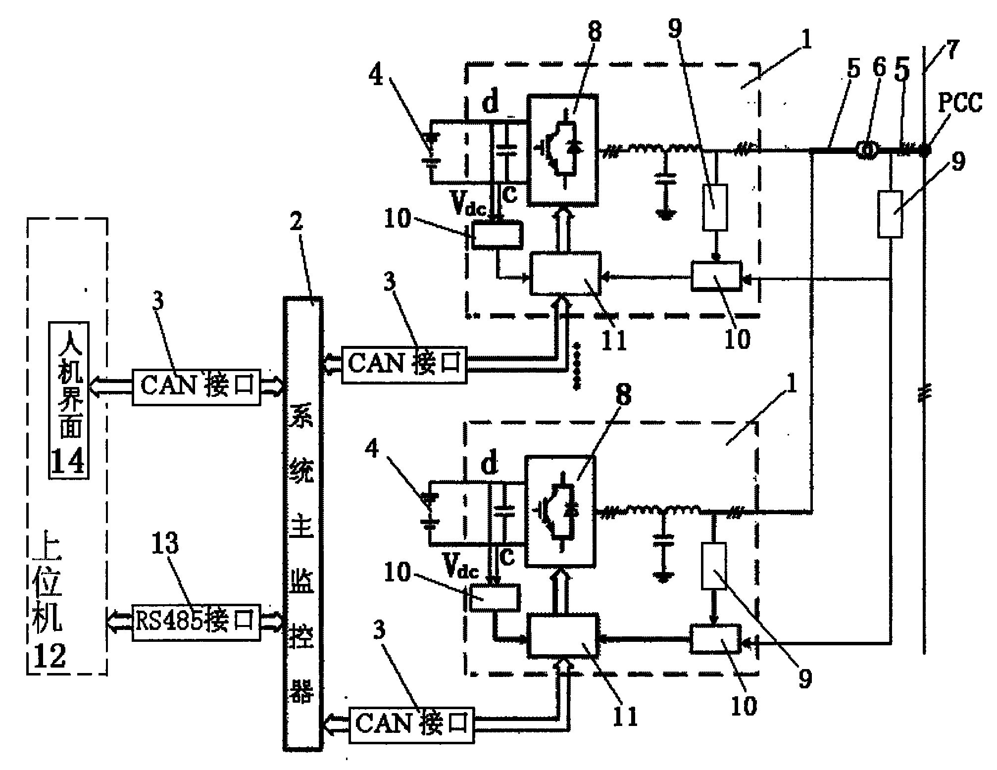
如图1所示,本发明包括至少两个充放电管理系统1、一系统主监控器2和若干CAN接口3。其中,充放电管理系统1与蓄电池组4一一对应,每一充放电管理系统1的直流端连接对应的蓄电池组4,并控制相应蓄电池组4进行充放电。各充放电系统1分别通过一CAN接口3与系统主监控器2进行信息交互,每一充放电管理系统1的交流侧并联接入一公共母线5上,再通过一变压器6接入高压主母线7(相当于电网),公共母线5与高压主母线7之间的接点形成一PCC点(Point of common coupling,公共耦合点),PCC点的电压和频率值的稳定,保证负荷11用电的稳定。本实施例中,蓄电池组4可以采用现有的钛酸锂电池、钠硫电池、液流电池、锂电池和铅酸电池中的任一种或多种。As shown in FIG. 1 , the present invention includes at least two charging and discharging management systems 1 , a system
本发明的每一充放电管理系统1包括一电压源逆变器8、若干电能要素采样器9、模数转换模块10和一DSP核心控制器11。其中,电压源逆变器8按照DSP核心控制器11的指令,与PCC点之间进行有功功率、无功功率双向调节,电压源逆变器8吸收有功功率时,即将高压主母线7上剩余的电量存储在蓄电池组4中;电压源逆变器8发出有功功率时,即蓄电池组4通过公共母线5给高压主母线7供电。电能要素采样器9用于采集高压主母线7的实际电能要素,电压源逆变器8与变压器6之间的公共母线5上的电能要素,以及蓄电池组4两端的电压Vdc。电能要素通常包括电压、频率和电流,本实施例中,电能要素采样器9可以是电压霍尔传感器和电流霍尔传感器。模数转换模块10将电能要素采样器9采集到的各种电能要素转换成数字信号。DSP核心控制器11中预设置有PCC点电压和频率值,以及蓄电池组4两端的上、下限电压值。DSP核心控制器11根据模数转换模块10输入的电能要素,控制PCC点电压和频率为预设值,同时判断蓄电池组4两端的电压值是否超出了预设的上、下限电压值,以控制电压源逆变器8和/或系统主监控器2的工作。Each charging and discharging management system 1 of the present invention includes a
DSP核心控制器11对系统主监控器2的控制情况是:一旦判断出蓄电池组4两端的电压值大于预设的上限电压值,DSP核心控制器11通过系统主监控器2,控制卸载负荷消耗掉高压主母线7输出的电能,使PCC点的电压和频率稳定为预设值。若判断出蓄电池组4两端的电压值小于预设的下限电压值,DSP核心控制器11通过系统主监控器2,控制外部备用电源启动,向高压主母线7供电,使PCC点的电压和频率稳定为预设值。The control situation of the
上述实施例中,本发明还包括一上位机12,其通过RS485接口13与系统主监控器2进行信息交互,以对本发明进行远程监测与控制。上位机12还包括一人机界面14,其通过CAN接口3与系统主监控器2进行信息交互,以对充放电管理系统1进行人机对话、远程控制等。In the above-mentioned embodiment, the present invention also includes a
本发明对电能进行调节的工作如下:The present invention regulates the work of electric energy as follows:
1)当DSP核心控制器11判断出PCC点的实际电压、频率值均大于预设的PCC点电压、频率值,且蓄电池组4两端的电压值位于预设的上、下限电压范围内时,电压源逆变器8吸收有功功率,即电压源逆变器8将高压主母线7中剩余的电能存储在蓄电池组4中,使PCC点电压、频率稳定为预设值。1) When the
2)当DSP核心控制器11判断出PCC点的实际电压、频率值均大于预设的PCC点电压、频率值,且蓄电池组4两端的电压值与预设上限电压值相等时,DSP核心控制器11通过系统主监控器2控制卸载负荷消耗掉高压主母线7输出的电能,使PCC点电压、频率稳定为预设值。2) When the
3)当DSP核心控制器11判断出PCC点的实际电压频率值小于预设的PCC点电压、频率值,且蓄电池组4两端的电压值位于预设的上、下限电压范围内时,电压源逆变器8发出有功功率,即电压源逆变器8将蓄电池组4中存储的电能通过公共母线5给高压主母线7供电,使PCC点电压、频率稳定为预设值。3) When the
4)当DSP核心控制器11判断出PCC点的实际电压频率值小于预设的PCC点电压、频率值,且蓄电池组4两端的电压值与预设的下限电压值相等时,DSP核心控制器11通过系统主监控器2启动外部备用电源给高压主母线7供电,使PCC点电压、频率稳定为预设值。4) When the
本发明通过与PCC点之间的有功功率、无功功率的双向调节,即四象限运行。在本发明与兆瓦级风电机组组成独立电源系统出现扰动时,本发明可以在额定范围内动态平衡独立电源系统的有功功率和无功功率,以控制PCC点的频率和电压稳定为预设值。The invention realizes two-way regulation of active power and reactive power between PCC points, that is, four-quadrant operation. When the independent power supply system composed of the present invention and the megawatt-level wind turbine is disturbed, the present invention can dynamically balance the active power and reactive power of the independent power supply system within the rated range, and control the frequency and voltage stability of the PCC point as the preset value .
上述各实施例仅用于说明本发明,其中各部件的结构、连接方式都是可以有所变化的,凡是在本发明技术方案的基础上进行的等同变换和改进,均不应排除在本发明的保护范围之外。Above-mentioned each embodiment is only for illustrating the present invention, and wherein the structure of each part, connection mode all can be changed to some extent, and all equivalent transformations and improvements carried out on the basis of the technical solution of the present invention should not be excluded from the scope of the present invention. outside the scope of protection.
Claims (8)
Priority Applications (1)
| Application Number | Priority Date | Filing Date | Title |
|---|---|---|---|
| CN2010101422784A CN101795005B (en) | 2010-04-02 | 2010-04-02 | Storage battery energy storage conditioning device |
Applications Claiming Priority (1)
| Application Number | Priority Date | Filing Date | Title |
|---|---|---|---|
| CN2010101422784A CN101795005B (en) | 2010-04-02 | 2010-04-02 | Storage battery energy storage conditioning device |
Publications (2)
| Publication Number | Publication Date |
|---|---|
| CN101795005A CN101795005A (en) | 2010-08-04 |
| CN101795005B true CN101795005B (en) | 2012-05-30 |
Family
ID=42587484
Family Applications (1)
| Application Number | Title | Priority Date | Filing Date |
|---|---|---|---|
| CN2010101422784A Active CN101795005B (en) | 2010-04-02 | 2010-04-02 | Storage battery energy storage conditioning device |
Country Status (1)
| Country | Link |
|---|---|
| CN (1) | CN101795005B (en) |
Families Citing this family (3)
| Publication number | Priority date | Publication date | Assignee | Title |
|---|---|---|---|---|
| CN102983585A (en) * | 2012-12-30 | 2013-03-20 | 东莞德世特电能科技有限公司 | Control method of intelligent energy storage system |
| US9075086B2 (en) * | 2013-05-24 | 2015-07-07 | Sierra Wireless, Inc. | Method and apparatus for determining time-varying limitations of a power source |
| CN107437816A (en) * | 2017-06-13 | 2017-12-05 | 沃太能源南通有限公司 | A kind of system and method for family energy-storage system dynamic regulation partial electric grid quality |
Citations (3)
| Publication number | Priority date | Publication date | Assignee | Title |
|---|---|---|---|---|
| CN101373896A (en) * | 2007-08-23 | 2009-02-25 | 上海星之辰电气传动技术有限公司 | Balance energy-saving device and operation method for power feeding system |
| CN101534013A (en) * | 2008-03-13 | 2009-09-16 | 通用电气公司 | Wind turbine energy storage and frequency control |
| CN201750159U (en) * | 2010-04-02 | 2011-02-16 | 中国海洋石油总公司 | A battery energy storage regulator |
Family Cites Families (2)
| Publication number | Priority date | Publication date | Assignee | Title |
|---|---|---|---|---|
| JPH03215130A (en) * | 1990-01-19 | 1991-09-20 | Toshiba Corp | Power storage system |
| JP5123673B2 (en) * | 2008-01-11 | 2013-01-23 | 東芝三菱電機産業システム株式会社 | Power converter |
-
2010
- 2010-04-02 CN CN2010101422784A patent/CN101795005B/en active Active
Patent Citations (3)
| Publication number | Priority date | Publication date | Assignee | Title |
|---|---|---|---|---|
| CN101373896A (en) * | 2007-08-23 | 2009-02-25 | 上海星之辰电气传动技术有限公司 | Balance energy-saving device and operation method for power feeding system |
| CN101534013A (en) * | 2008-03-13 | 2009-09-16 | 通用电气公司 | Wind turbine energy storage and frequency control |
| CN201750159U (en) * | 2010-04-02 | 2011-02-16 | 中国海洋石油总公司 | A battery energy storage regulator |
Non-Patent Citations (2)
| Title |
|---|
| JP平3-215130A 1991.09.20 |
| JP特开2009-171652A 2009.07.30 |
Also Published As
| Publication number | Publication date |
|---|---|
| CN101795005A (en) | 2010-08-04 |
Similar Documents
| Publication | Publication Date | Title |
|---|---|---|
| CN103427430B (en) | A kind of energy management method of mixed energy storage system in microgrid | |
| CN102522763B (en) | Control method for stabilizing fluctuation of wind power by energy storage system | |
| TWI527336B (en) | Energy storage module and energy storage apparatus | |
| CN201312133Y (en) | Charging device, energy-storing device and charging station | |
| CN101794997B (en) | Megawatt wind power storage battery combined independent power supply system | |
| CN102738836A (en) | Alternating current and direct current hybrid micro power grid system and control method thereof | |
| CN106961150B (en) | Control method and system of composite energy storage battery | |
| EP3627648A1 (en) | Hybrid energy storage system | |
| CN204681125U (en) | A kind of charging system for electric automobile based on solar energy | |
| WO2022198635A1 (en) | Energy storage system and control method therefor | |
| CN104682412A (en) | Energy control method of energy storage system of permanent magnet synchronous wind power system | |
| CN106356975A (en) | Microsatellite energy system | |
| CN101728835A (en) | Battery power energy storing device for smoothing output power of wind power generation | |
| CN102931688B (en) | Combined regenerative energy power supply device | |
| CN108173286A (en) | A kind of intelligent battery energy-storage system | |
| CN101795005B (en) | Storage battery energy storage conditioning device | |
| Xu et al. | Energy management and control strategy for DC micro-grid in data center | |
| CN201518421U (en) | Microgrid solar photovoltaic power supply device | |
| EP4354690A1 (en) | Electricity storage system | |
| CN201699416U (en) | A megawatt-level wind power battery combined independent power system | |
| CN201750159U (en) | A battery energy storage regulator | |
| CN218678462U (en) | Energy storage converter, energy storage system and new energy power generation system | |
| Mao et al. | Research on hybrid energy storage system with high power density and high energy density | |
| CN116247711A (en) | An energy storage system based on load priority control | |
| CN202772602U (en) | Wind power generation system possessing off-grid mode and grid-connected mode |
Legal Events
| Date | Code | Title | Description |
|---|---|---|---|
| C06 | Publication | ||
| PB01 | Publication | ||
| C10 | Entry into substantive examination | ||
| SE01 | Entry into force of request for substantive examination | ||
| C14 | Grant of patent or utility model | ||
| GR01 | Patent grant |