CN1017226B - The mixer of preparation fibre concrete mixture - Google Patents
The mixer of preparation fibre concrete mixtureInfo
- Publication number
- CN1017226B CN1017226B CN 87100188 CN87100188A CN1017226B CN 1017226 B CN1017226 B CN 1017226B CN 87100188 CN87100188 CN 87100188 CN 87100188 A CN87100188 A CN 87100188A CN 1017226 B CN1017226 B CN 1017226B
- Authority
- CN
- China
- Prior art keywords
- spiral
- diameter
- mixer
- mixing cylinder
- vertical axis
- Prior art date
- Legal status (The legal status is an assumption and is not a legal conclusion. Google has not performed a legal analysis and makes no representation as to the accuracy of the status listed.)
- Expired
Links
Images

Landscapes
- Preparation Of Clay, And Manufacture Of Mixtures Containing Clay Or Cement (AREA)
- Mixers Of The Rotary Stirring Type (AREA)
Abstract
The equipment of being advised is predefined in industry and the various fields of municipal works are used to prepare fibre concrete mixture.
Mixer has a rotatable mix tube (5), and it can hold a working component that is made of many spirals (8), and spiral (8) can be around its axle rotation.Each spiral shell is so (8) have equal diameter (d) and pitch (t), and equidistantly the highland is placed to such an extent that approach the diameter (D) of mixing cylinder (5).Adjacent spiral (8) rotates in the opposite direction, and the distance between its vertical axis is less than its diameter (d), and diameter (d) is determined by following formula:
D is the diameter of mixing cylinder in the formula; With
N is natural number 〉=3.
Description
The present invention relates to prepare the mixer of fibre concrete mixture.
One of up-to-date construction material is a glass reinforced concrete glass, and it allows to use to reduce the consumption of concrete and steel under some occasion, allows to save fully reinforcing bar in some cases.
Fiber concrete can be stacked concrete permanent framework, the safeguard structure that overhangs, ventilation component road deck, windowsill, crossbanding or the like with manufacturing plate lining, balcony fence, pipe element, job site.
A large amount of articles from fibrous concrete is arranged now, and the physical and mechanical property of articles from fibrous concrete is very important.For improving these performances, need come pressing with low slump or universe compound, keep simultaneously containing glass fibre compound uniformity and avoid conglomeration when slightly mixing material so that all fibres is wrapped up by laitance.
The known mixer that is used to prepare high viscosity material and compound be a garden cylindrical container it an elastic housing is arranged, make to form an inflatable chamber in it, also have an agitator that links to each other with drive member, make it to rotate around its vertical axis.Agitator is made one group of spiral of imaging, and arranges to such an extent that be eccentric in the symmetry axis of container; Drive member has a mechanism that makes rotatable spiral do cycloid motion (consulting for example Soviet Union's certificate of invention № .893560, IPC B28C5/16).
A shortcoming of this kind mixer is, owing to produce high shear stress between rotating spoon and elastic housing, fiber certainly will be by mechanical failure, and compound can not make that fibre bundle is loose to be opened simultaneously, can not guarantee that fiber evenly distributes in compound.In addition, fiber can have enough dispersions to strengthen so can not guarantee compound on spiral; Owing to the rubbing action of the filler in compound, elastic housing is easily ground away simultaneously.
The objective of the invention is to be to provide a kind of mixer for preparing fibre concrete mixture, its working component should build to such an extent that make fiber uniformly dispersing in compound, avoid its damage simultaneously and guarantee that whole compound is even.
Target of the present invention is achieved like this, and promptly in the mixer of preparation fibre concrete mixture a mixing cylinder is arranged, and it holds a working component that is made of a plurality of spirals, and each spiral can both be around its vertical axis rotation; According to the present invention, mixing cylinder and working component each spiral that can relatively move has equal pitch and diameter, and places to such an extent that approach the diameter of mixing cylinder equidistantly; Adjacent spiral rotates in the opposite direction, and the distance between its vertical axis is less than its diameter, and screw diameter is determined by following formula:
d= (1·2·D)/(2n+1) ,
D is the diameter of mixing cylinder in the formula; With
N is natural number 〉=3.
The structure of mixer working component of the present invention makes in mixing cylinder can evenly mix material, and the distance between the vertical axis of each spiral predetermined is guaranteed that they stretch into each other, thereby fiber harness is by loose and be evenly distributed in the compound, and avoids conglomeration.Make and produce uniform compound.
Best, the inclination angle on the plane that each spiral winding is perpendicular with respect to perpendicular axle is between 10 ° to 30 °.
When inclination angle during less than 10 °, fiber enters compound with slow rate, and the result is caused that by screw extrusion fiber may be damaged.
On the contrary, when inclination angle during greater than 30 °, acutely increase the perpendicular flow of compound, thereby must reduce the rotating speed of spiral, fiber may be around to spiral as a result.
According to an alternative embodiment of the invention, the lower end of each spiral is taper, and the vertex of a cone is in the face of the tube end.
It is around to spiral for fear of fiber that spiral lower end is made this shape.
In another embodiment of the present invention, the length of the tapered lower end of each spiral is (0.1~0.2) t, and t is the pitch of spiral here.
Such layout is favourable, because significantly reduced the frictional force between mixing cylinder bottom and the compound, this has been avoided fiber around the trend to spiral.
The tapered lower end of each spiral has a distance from its vertical axis, and it equals screw diameter partly.
This arrangement of spiral end also is that intention prevents that fiber is around the trend to spiral.
With reference now to various preferred embodiments, also come to describe in more detail the present invention in conjunction with the accompanying drawings, these accompanying drawings are:
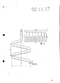
Fig. 1 is the total figure of mixer of the present invention under in working order;
Fig. 2 represents the situation of mixer of the present invention when unloading compound from mixing cylinder;
Fig. 3 is the schematic diagram of the working component of mixer of the present invention;
Figure 4 and 5 represent to have the working component of different spiral numbers,
Fig. 6 is an example of the spiral of mixer working component of the present invention.
Mixer has a framework 1(Fig. 1 and 2), its underpart is provided with a whirligig 2, and it is contained in the plain bearing and a lever 3 and a locking piece 4 is arranged.Mixing cylinder 5 is installed on the device 2, and this tube has one for making tube 5 around vertical axis N-N(Fig. 3) drive unit 6 of rotation.Fibre concrete mixture is stirred in tube 5 by working component 7, and member 7 has helical member 8, and it can be around its vertical axis 0-0 rotation (Fig. 6), and each spiral is equidistant to be placed to such an extent that approach diameter D(Fig. 3 to 5 of tube 5).Spiral 8 is by drive unit 9 rotations (Fig. 1 and 2), and adjacent spiral 8 is rotated in the opposite direction.Each spiral 8 has equal pitch t(Fig. 6) and diameter d, the latter is determined by following formula:
d= (1.2·D)/(2n+1) ,
D is the diameter of mixing cylinder in the formula; With
N is natural number 〉=3.
Distance between the vertical axis 0-0 of each spiral 8 is preferably less than its diameter d.The inclination angle on the plane that each spiral winding is perpendicular with respect to perpendicular axle 0-0 is preferably 10~30 °.The lower end of each spiral 8 is taper (Fig. 6), and the vertex of a cone is in the face of the end of tube 5.
The length l of the tapered lower end of each spiral 8 is (0.1~0.2) t, and the tapering point of each spiral 8 has a distance from its vertical axis 0-0, equals screw diameter d partly.
The top of framework 1 is provided with a lifting device 10(Fig. 1,2), it has the working component of hanging on steel hinge line 11 7, manually operates by chain device 13 by a handwheel 12, or operates by a transmission gear for electric motor (not shown).
Mixer of the invention process moves in following mode.
Before bringing into operation, working component 7 is raised by chain device 13 and steel hinge line 11 by rotation hand wheel 12.Make tube 5 be locked in the operating position with locking piece 4, after this, binding material, filler and water are packed in the tube 5.Then working component 7 by lifting device 10 landing go in the tube 5 presenting duty, and give drive unit 9 power supplies of working component 7.The drive unit 6 of operation tube 5 is so that tube 5 rotations then.Mix in advance the material 46 seconds after, add fiber.1.5 after 2 minutes, working component 7 raises up (drive unit 6 and 9 of tube 5 and working component 7 has cut off the power supply, and locking piece 4 has been thrown off) from tube 5.By using whirligig 2, tube 5 is reversed to unload final compound (Fig. 2) then.After this, tube 5 is turned to initial position.For preventing that compound from sticking on tube 5 the wall (Figure 4 and 5), the spiral number of working component 7 is preferably odd number (2n+l) and the direction of rotation of spiral 8 outermost or the edge is opposite with the direction of rotation of mixing cylinder 5.Natural number n 〉=3 are more desirable, and this is in order to increase the purpose that the compound horizontal direction flows, and in order to make compound stir effectivelyer and to improve the efficient of mixer.For example, when the diameter of mixing cylinder 5 was 800 millimeters (D=800 millimeters) and n=4, the number of spiral 8 was (2n+1)=9.
D=(1.2 * 800)/9=106 millimeter,
During identical and n=5, the number of spiral 8 will be (2n+1)=11 as the diameter D of mixing cylinder.
D=(1.2 * 800)/11=87 millimeter,
Select the optimum diameter d of spiral 8 according to the parameter of used fiber.
The rotary speed of spiral 8 is considerable.The most desirable rotary speed of spiral 8 is in the scope of 450 to 1000 cycle per minutes, and this diameter with the enhancing rate of fiber and spiral 8 is relevant.Lower speed can not cause fiber harness loose fully, and the result influences the quality of compound, thereby makes final products reduce intensity, and this is to utilize the reason of disperseing enhancing fully.
In pressing another modification of the present invention, mixing cylinder 5 is fixed, and working component 7 can be around the axle N-N of tube 5 rotation.
Claims (5)
1, a kind of mixer for preparing fibre concrete mixture, it has a mixing cylinder (5), this mixing cylinder is provided with a working component (7) by many spirals (8) formation, and spiral (8) can be around its vertical axis (0-0) rotation, and mixing cylinder (5) and working component (7) can relatively move; It is characterized in that being that each spiral (8) has equal pitch (t) and diameter (d), and place to such an extent that approach the diameter (D) of mixing cylinder (5) equidistantly, adjacent spiral (8) rotates in the opposite direction, and the distance between its vertical axis (0-0) is less than its diameter (d), and diameter (d) is determined by following formula:
d= (1.2·D)/(2n+1) ,
D is the diameter of mixing cylinder in the formula; With
N is the natural number more than or equal to 3.
2, according to the desired mixer of claim 1, its characteristics are that the inclination angle on the plane that the spiral winding of each spiral (8) is perpendicular with respect to perpendicular axis (0-0) is between 10 °~30 °.
3, according to the desired mixer of claim 1, its characteristics are that the lower end of each spiral (8) is tapered, and the vertex of a cone is towards the end of tube (5).
4, according to the desired mixer of claim 3, its characteristics are that the length (l) of the tapered lower end of each spiral (8) is (0.1~0.2) t, and t is the pitch of spiral (8) here.
5, according to claim 3 or 4 desired mixers, its characteristics are that the tapered lower end of each spiral (8) has a distance from its vertical axis (0-0), and it equals half of screw diameter (d).
Priority Applications (1)
| Application Number | Priority Date | Filing Date | Title |
|---|---|---|---|
| CN 87100188 CN1017226B (en) | 1987-01-12 | 1987-01-12 | The mixer of preparation fibre concrete mixture |
Applications Claiming Priority (1)
| Application Number | Priority Date | Filing Date | Title |
|---|---|---|---|
| CN 87100188 CN1017226B (en) | 1987-01-12 | 1987-01-12 | The mixer of preparation fibre concrete mixture |
Publications (2)
| Publication Number | Publication Date |
|---|---|
| CN87100188A CN87100188A (en) | 1988-07-27 |
| CN1017226B true CN1017226B (en) | 1992-07-01 |
Family
ID=4812745
Family Applications (1)
| Application Number | Title | Priority Date | Filing Date |
|---|---|---|---|
| CN 87100188 Expired CN1017226B (en) | 1987-01-12 | 1987-01-12 | The mixer of preparation fibre concrete mixture |
Country Status (1)
| Country | Link |
|---|---|
| CN (1) | CN1017226B (en) |
Families Citing this family (3)
| Publication number | Priority date | Publication date | Assignee | Title |
|---|---|---|---|---|
| CN100417504C (en) * | 2005-03-09 | 2008-09-10 | 湖南科技大学 | A mixer for carbon fiber mixtures |
| TR201910115T4 (en) * | 2012-12-05 | 2019-07-22 | Yoshino Gypsum Co | Mixing and agitating device, mixing and shaking method and method of producing low weight gypsum board. |
| CN105034171B (en) * | 2015-08-26 | 2018-06-26 | 山东大学 | Superhigh tenacity cement-base composite material blender and its application method |
-
1987
- 1987-01-12 CN CN 87100188 patent/CN1017226B/en not_active Expired
Also Published As
| Publication number | Publication date |
|---|---|
| CN87100188A (en) | 1988-07-27 |
Similar Documents
| Publication | Publication Date | Title |
|---|---|---|
| CN107877698A (en) | A kind of stirring integrated machine of dry and wet powder for building | |
| CN209649131U (en) | A kind of concrete central mix plant | |
| CN209036734U (en) | A kind of blender rabbling mechanism | |
| CN1017226B (en) | The mixer of preparation fibre concrete mixture | |
| CN110576516A (en) | Building mixer that stirring is more even | |
| CN201067678Y (en) | Horizontal stirring machine with improved stirring device | |
| CN2197116Y (en) | Movable cement mixing device | |
| CN113004717A (en) | Preparation process of superfine modified heavy calcium carbonate | |
| CN212528201U (en) | Mortar stirring device | |
| CN207736506U (en) | One kind is laid bricks mortar stirring device | |
| CN213946946U (en) | Horizontal shaft type 60-liter concrete test mixer for concrete production | |
| CN213226903U (en) | Concrete mixing device for building | |
| CN113829501A (en) | Mixing arrangement is used in building material processing | |
| CN115229984A (en) | Recycled concrete homogeneous mixing agitated vessel | |
| CN114770738A (en) | Processing device for preparing cement grouting material and preparation method of grouting material | |
| CN206613430U (en) | Mixer | |
| CN219748481U (en) | Watering device is used in concrete production | |
| CN220517165U (en) | Water conservancy construction concrete mixer | |
| CN208097876U (en) | A kind of Chemical Manufacture blender | |
| CN221021711U (en) | Concrete reinforcing fiber preparation device | |
| CN215511630U (en) | Concrete mixing device for construction | |
| CN219466541U (en) | High-performance mortar stirring device | |
| CN222178225U (en) | A concrete mixing equipment with uniform mixing | |
| CN221314662U (en) | Mortar stirring device for mortar production | |
| JP3529879B2 (en) | Concrete injection machine and concrete kneading method |
Legal Events
| Date | Code | Title | Description |
|---|---|---|---|
| C06 | Publication | ||
| PB01 | Publication | ||
| C10 | Entry into substantive examination | ||
| SE01 | Entry into force of request for substantive examination | ||
| C13 | Decision | ||
| GR02 | Examined patent application | ||
| AD01 | Patent right deemed abandoned | ||
| C20 | Patent right or utility model deemed to be abandoned or is abandoned |