CN101460659B - Gas flow control by differential pressure measurements - Google Patents
Gas flow control by differential pressure measurements Download PDFInfo
- Publication number
- CN101460659B CN101460659B CN2007800203964A CN200780020396A CN101460659B CN 101460659 B CN101460659 B CN 101460659B CN 2007800203964 A CN2007800203964 A CN 2007800203964A CN 200780020396 A CN200780020396 A CN 200780020396A CN 101460659 B CN101460659 B CN 101460659B
- Authority
- CN
- China
- Prior art keywords
- gas
- flow
- those
- nozzle
- nozzles
- Prior art date
- Legal status (The legal status is an assumption and is not a legal conclusion. Google has not performed a legal analysis and makes no representation as to the accuracy of the status listed.)
- Expired - Fee Related
Links
Images


Classifications
-
- C—CHEMISTRY; METALLURGY
- C23—COATING METALLIC MATERIAL; COATING MATERIAL WITH METALLIC MATERIAL; CHEMICAL SURFACE TREATMENT; DIFFUSION TREATMENT OF METALLIC MATERIAL; COATING BY VACUUM EVAPORATION, BY SPUTTERING, BY ION IMPLANTATION OR BY CHEMICAL VAPOUR DEPOSITION, IN GENERAL; INHIBITING CORROSION OF METALLIC MATERIAL OR INCRUSTATION IN GENERAL
- C23C—COATING METALLIC MATERIAL; COATING MATERIAL WITH METALLIC MATERIAL; SURFACE TREATMENT OF METALLIC MATERIAL BY DIFFUSION INTO THE SURFACE, BY CHEMICAL CONVERSION OR SUBSTITUTION; COATING BY VACUUM EVAPORATION, BY SPUTTERING, BY ION IMPLANTATION OR BY CHEMICAL VAPOUR DEPOSITION, IN GENERAL
- C23C16/00—Chemical coating by decomposition of gaseous compounds, without leaving reaction products of surface material in the coating, i.e. chemical vapour deposition [CVD] processes
- C23C16/44—Chemical coating by decomposition of gaseous compounds, without leaving reaction products of surface material in the coating, i.e. chemical vapour deposition [CVD] processes characterised by the method of coating
- C23C16/52—Controlling or regulating the coating process
-
- C—CHEMISTRY; METALLURGY
- C23—COATING METALLIC MATERIAL; COATING MATERIAL WITH METALLIC MATERIAL; CHEMICAL SURFACE TREATMENT; DIFFUSION TREATMENT OF METALLIC MATERIAL; COATING BY VACUUM EVAPORATION, BY SPUTTERING, BY ION IMPLANTATION OR BY CHEMICAL VAPOUR DEPOSITION, IN GENERAL; INHIBITING CORROSION OF METALLIC MATERIAL OR INCRUSTATION IN GENERAL
- C23C—COATING METALLIC MATERIAL; COATING MATERIAL WITH METALLIC MATERIAL; SURFACE TREATMENT OF METALLIC MATERIAL BY DIFFUSION INTO THE SURFACE, BY CHEMICAL CONVERSION OR SUBSTITUTION; COATING BY VACUUM EVAPORATION, BY SPUTTERING, BY ION IMPLANTATION OR BY CHEMICAL VAPOUR DEPOSITION, IN GENERAL
- C23C16/00—Chemical coating by decomposition of gaseous compounds, without leaving reaction products of surface material in the coating, i.e. chemical vapour deposition [CVD] processes
- C23C16/44—Chemical coating by decomposition of gaseous compounds, without leaving reaction products of surface material in the coating, i.e. chemical vapour deposition [CVD] processes characterised by the method of coating
- C23C16/455—Chemical coating by decomposition of gaseous compounds, without leaving reaction products of surface material in the coating, i.e. chemical vapour deposition [CVD] processes characterised by the method of coating characterised by the method used for introducing gases into reaction chamber or for modifying gas flows in reaction chamber
- C23C16/45557—Pulsed pressure or control pressure
-
- Y—GENERAL TAGGING OF NEW TECHNOLOGICAL DEVELOPMENTS; GENERAL TAGGING OF CROSS-SECTIONAL TECHNOLOGIES SPANNING OVER SEVERAL SECTIONS OF THE IPC; TECHNICAL SUBJECTS COVERED BY FORMER USPC CROSS-REFERENCE ART COLLECTIONS [XRACs] AND DIGESTS
- Y10—TECHNICAL SUBJECTS COVERED BY FORMER USPC
- Y10T—TECHNICAL SUBJECTS COVERED BY FORMER US CLASSIFICATION
- Y10T137/00—Fluid handling
- Y10T137/7722—Line condition change responsive valves
- Y10T137/7758—Pilot or servo controlled
- Y10T137/7761—Electrically actuated valve
Landscapes
- Chemical & Material Sciences (AREA)
- General Chemical & Material Sciences (AREA)
- Chemical Kinetics & Catalysis (AREA)
- Engineering & Computer Science (AREA)
- Materials Engineering (AREA)
- Mechanical Engineering (AREA)
- Metallurgy (AREA)
- Organic Chemistry (AREA)
- Measuring Volume Flow (AREA)
- Sampling And Sample Adjustment (AREA)
Abstract
本发明揭露一种气体流比较器,其包含一安装于一气体管上以设定通过气体管的气体的气体流量或压力的气体控制单元。一主要分流器包含一连接至气体管的入口端口。第一及第二限流器为连接至主要分流器。一对辅助分流器为各自连接至一限流器的限流器出口。一压差计是连接至辅助分流器。一对喷嘴托架连接至第二分流器,且可连接至第一及第二喷嘴。在操作中,压差计呈现与通过第一与第二喷嘴的气体流速的差异成比例的压差。
This invention discloses a gas flow comparator comprising a gas control unit mounted on a gas tube to set the gas flow rate or pressure of gas passing through the gas tube. A main distributor includes an inlet port connected to the gas tube. First and second flow restrictors are connected to the main distributor. A pair of auxiliary distributors are each connected to the flow restrictor outlet of a flow restrictor. A differential pressure gauge is connected to the auxiliary distributors. A pair of nozzle holders are connected to a second distributor and can be connected to the first and second nozzles. In operation, the differential pressure gauge presents a pressure differential proportional to the difference in gas flow rate through the first and second nozzles.
Description
技术领域 technical field
本发明有关应用压差测量的气体流调控。The present invention relates to gas flow regulation using differential pressure measurement.
背景技术 Background technique
在电子电路及显示器制造中,例如半导体、介电材料及导体材料的材料是沉积及图样化于一基材上。部分的此些材料由化学气相沉积(CVD)或物理气相沉积(PVD)工艺来进行沉积,而其它材料则由基材材料的氧化作用或氮化作用而形成。例如,在化学气相沉积工艺中,工艺气体导入反应室中,并通过加热或RF能激发的而沉积一膜于基材上。在物理气相沉积中,一靶材是以工艺气体溅镀而沉积一层靶材材料于基材上。在蚀刻工艺中,一含有光阻或硬式光罩的图样化光罩通过微影术形成于基材表面上,且暴露于光罩特征结构间的基材表面部分是由激发态的工艺气体蚀刻的。此工艺气体可为单一气体或一气体混合物。沉积及蚀刻工艺,及额外的平坦化工艺依序进行以处理基材而制造电子装置及显示器。In the manufacture of electronic circuits and displays, materials such as semiconductors, dielectric materials and conductive materials are deposited and patterned on a substrate. Some of these materials are deposited by chemical vapor deposition (CVD) or physical vapor deposition (PVD) processes, while others are formed by oxidation or nitridation of the substrate material. For example, in a chemical vapor deposition process, process gases are introduced into a reaction chamber and excited by heat or RF energy to deposit a film on a substrate. In physical vapor deposition, a target is sputtered with a process gas to deposit a layer of target material on a substrate. In the etch process, a patterned mask containing a photoresist or hard mask is formed on the substrate surface by lithography, and the portion of the substrate surface exposed between the mask features is etched by an excited state process gas of. The process gas can be a single gas or a mixture of gases. Deposition and etching processes, and additional planarization processes are performed sequentially to prepare the substrate for the fabrication of electronic devices and displays.
基材处理反应室包含有气体分配器,其包括多个气体喷嘴以导入工艺气体至反应室中。在一态样中,气体分配器为一包含具有多个气体喷嘴的板或包围室的喷气头。另一态样中,气体分配器包含独立气体喷嘴,其通过反应室侧壁以由围绕基材周边的侧向注入至反应室。在另一态样中,多个独立气体喷嘴由围绕基材周边垂直注入气体至反应室。在再一态样中,气体分配器包含具有面对基材的气体出口数组的喷气头。The substrate processing reaction chamber includes a gas distributor, which includes a plurality of gas nozzles for introducing process gas into the reaction chamber. In one aspect, the gas distributor is a gas shower head comprising a plate or enclosure with a plurality of gas nozzles. In another aspect, the gas distributor includes individual gas nozzles that inject into the reaction chamber from the side around the periphery of the substrate through the reaction chamber sidewall. In another aspect, a plurality of independent gas nozzles inject gas into the reaction chamber vertically around the substrate perimeter. In yet another aspect, the gas distributor includes a gas showerhead having an array of gas outlets facing the substrate.
然而,传统气体分配器通常不能提供跨越基材表面的均一分布的气体流。例如,一含有不同气体喷嘴的气体分配器通常由不同喷嘴通过不同的气体流速,当例如气体喷嘴的大小在喷嘴间彼此不同时。如另一例子,一喷气头通常具有稍微不同直径的出口孔,其将导致每一出口孔的不同流速。再者,在某些设计中,含有具不同直径出口数组的气体喷气头可提供在一特定出口数组中的不同出口的不同气体流速。However, conventional gas distributors often cannot provide a uniformly distributed gas flow across the substrate surface. For example, a gas distributor having different gas nozzles typically passes different gas flow rates from the different nozzles when, for example, the size of the gas nozzles differs from nozzle to nozzle. As another example, an air sparger typically has outlet holes of slightly different diameters, which will result in different flow rates for each outlet hole. Furthermore, in some designs, gas injection heads having arrays of outlets with different diameters can provide different gas flow rates at different outlets in a particular array of outlets.
更进一步的问题发生在当尝试平衡多反应室处理设备的二分离反应室的气体流以获得在每一反应室为实质相似处理速率时。在一方法中,使用微计量阀调整通过一供应至反应室的一管的工艺气体流,例如在共同受让的美国专利第6,843,882号描述者,将其全文并入以做为本案的参考。可调整独立的微计量阀以平衡或蓄意不平衡二不同反应室的气体流。然而,微计量计的人工调整为耗费人工且可造成操作人员的不精确。操作人员的物理调整微计量计一定次数,且此调整可因操作者不经意的作动而改变。再者,对每一反应室的平衡气体流的精确等级亦通常难以决定。A further problem arises when attempting to balance the gas flow in two separate chambers of a multi-chamber processing apparatus to obtain substantially similar processing rates in each chamber. In one approach, micrometering valves are used to regulate the flow of process gas through a tube supplying the reaction chamber, such as described in commonly assigned US Patent No. 6,843,882, which is incorporated by reference in its entirety. Independent micrometering valves can be adjusted to balance or deliberately unbalance the gas flow of the two different reaction chambers. However, manual adjustment of micrometers is labor intensive and can introduce operator inaccuracies. The operator physically adjusts the micrometer a certain number of times, and this adjustment can be changed by inadvertent operator actions. Furthermore, the precise level of equilibrium gas flow to each reaction chamber is often difficult to determine.
亦可使用可分离输入气体流成为二独立流的流量比装置(flow ratiodevice)来控制气体流至双反应室。例如,美国麻州威明顿MKSInstruments公司的DELTATM流量比控制器可将输入流分成二独立流。另一流体控制装置,美国加州密耳比它斯Celerity公司的流量比分流器(RatioFlow Splitter;RFS)模块是基于传送至反应室的多个区域或独立反应室的一特定设定点的比例而利用一阀将输入气体流转向至二分支气体流。在此些装置中,流至每一反应室的流体是以流量计量测。虽然此装置为有效的,但比例的精确性受流量计的精确性强力影响,其通常为流量比例的±1%。可使用较精确的流量计以得较佳精确性,然而,此流量计为昂贵的且增加基材处理成本。Flow ratio devices can also be used to control the flow of gas to the dual reaction chambers by separating the input gas stream into two separate streams. For example, the DELTA (TM) Flow Ratio Controller from MKS Instruments, Inc., Wilmington, MA, USA splits the incoming stream into two independent streams. Another fluid control device, the Flow Ratio Splitter (RatioFlow Splitter; RFS) module of Celerity Company of Mil Beetles, California, USA, is based on the ratio of a specific set point delivered to multiple regions of the reaction chamber or independent reaction chambers. A valve is used to divert the input gas flow to the two branched gas flows. In these devices, fluid flow to each reaction chamber is measured in flow meters. While this device is effective, the accuracy of the ratio is strongly affected by the accuracy of the flow meter, which is typically ±1% of the flow ratio. More accurate flow meters can be used for better accuracy, however, such flow meters are expensive and add to substrate processing costs.
因此,需要具有一气体分配器,其经由不同的喷嘴提供已知及可再现的流速,以提供跨越基材表面的均匀或预设的处理流速。亦需要一精确量测通过气体分配器的不同喷嘴的气体流速。又需要一可调整流至双反应室的气体流量以获得在每一反应室中的均匀流速。Therefore, it is desirable to have a gas distributor that provides known and reproducible flow rates through different nozzles to provide a uniform or preset process flow rate across the substrate surface. There is also a need for an accurate measurement of the gas flow rate through the various nozzles of the gas distributor. There is also a need for an adjustable gas flow to the dual reaction chambers to obtain a uniform flow rate in each reaction chamber.
发明内容 Contents of the invention
本发明是揭露一种气体流比较器,该比较器包含:(a)一气体控制单元,是安装于一气体管上,气体控制单元包含一气体控制回馈环路以控制通过气体管的一气体的一流速或压力;(b)一主要分流器,其包含一入口端口及一对输出端口,入口端口是用以由气体管接受气体;(c)一对限流器,各个限流器是连接至主要分流器的一输出端口,且各个限流器具有一限流器出口;(d)一对辅助分流器,各个辅助分流器是连接至一限流器的一限流器出口,且各个辅助分流器包含一对的第一及第二输出端口;(e)一压差计,是连接至辅助分流器的第一输出端口二者;以及(f)一对喷嘴托架,各个喷嘴托架是连接至一辅助分流器的一第二输出端口,喷嘴托架可连接至第一及第二喷嘴,藉此,通过限流器及第一与第二喷嘴的气体会造成压差计呈现一与气体通过第一与第二喷嘴的流速的差异成比例的压差。The present invention discloses a gas flow comparator, which includes: (a) a gas control unit installed on a gas pipe, the gas control unit includes a gas control feedback loop to control a gas passing through the gas pipe (b) a main flow divider, which includes an inlet port and a pair of output ports, the inlet port is used to receive gas from the gas tube; (c) a pair of flow restrictors, each of which is connected to an output port of the primary flow divider, and each flow restrictor has a flow limiter outlet; (d) a pair of auxiliary flow dividers, each auxiliary flow divider is connected to a flow limiter outlet of a flow limiter, and each The auxiliary flow splitter includes a pair of first and second output ports; (e) a differential pressure gauge connected to both of the first output ports of the auxiliary flow splitter; and (f) a pair of nozzle holders, each nozzle holder The bracket is connected to a second output port of an auxiliary flow divider. The nozzle bracket can be connected to the first and second nozzles, whereby the gas passing through the restrictor and the first and second nozzles will cause the differential pressure gauge to show A differential pressure proportional to the difference in flow rates of gas through the first and second nozzles.
本发明又揭露一种气体流控制器,其包含如上述的气体流比较器,且其中第一及第二喷嘴各自包含流量调节阀,该些流量调节阀的一端是连接至一辅助分流器的一第二输出端口,且另一端则连接至一基材处理反应室的一气体入口管,气体入口管是供给在反应室中的一气体分配器;且其中气体流控制器是相应于由压差计所接收的一讯号来调节流量调节阀,以控制流经流量调节阀的气体流量。The present invention also discloses a gas flow controller, which includes the above-mentioned gas flow comparator, and wherein each of the first and second nozzles includes a flow regulating valve, and one end of the flow regulating valve is connected to an auxiliary flow divider A second output port, and the other end is connected to a gas inlet pipe of a substrate processing reaction chamber, the gas inlet pipe is supplied to a gas distributor in the reaction chamber; and wherein the gas flow controller is corresponding to the pressure A signal received by the differential meter is used to adjust the flow regulating valve, so as to control the flow of gas flowing through the flow regulating valve.
本发明更揭露一种基材处理设备,其包含如上述的气体流控制器,且其中该设备包含一第一处理反应室及一第二处理反应室,而各个反应室包含一供应一气体分配器的气体入口管、一面向气体分配器的基材支撑座,以及一排出端口,气体是通过排出端口而排出。The present invention further discloses a substrate processing equipment, which comprises the above-mentioned gas flow controller, and wherein the equipment comprises a first processing reaction chamber and a second processing reaction chamber, and each reaction chamber comprises a supply and a gas distribution A gas inlet pipe of the device, a substrate support seat facing the gas distributor, and a discharge port through which the gas is discharged.
本发明更揭露一种用于具有双反应室的一基材处理设备的气体分配器,该气体分配器包含:(a)一面板,具有一输入气体歧管以及一背侧孔,该背侧孔是能够被连接至一压差计;以及(b)一阻挡板,是面向该面板,该阻挡板包括数个喷嘴。The present invention further discloses a gas distributor for a substrate processing apparatus with dual reaction chambers, the gas distributor comprising: (a) a panel with an input gas manifold and a backside port, the backside The holes are capable of being connected to a differential pressure gauge; and (b) a baffle plate is facing the panel, the baffle plate includes nozzles.
本发明又揭露一种基材处理设备,其包含如上述的该气体分配器,且其中该设备包含一第一处理反应室及一第二处理反应室,而各个反应室包含一气体分配器、一面向该气体分配器的基材支撑座,以及一排出端口,气体是通过排出端口而排出。The present invention also discloses a substrate processing equipment, which includes the above-mentioned gas distributor, and wherein the equipment includes a first processing reaction chamber and a second processing reaction chamber, and each reaction chamber includes a gas distributor, A substrate supporting base facing the gas distributor, and an exhaust port through which the gas is discharged.
本发明更揭露一种用于具有第一及第二反应室的一基材处理设备的气体流控制系统,该系统包括:(a)一第一气体分配器,包括一第一输入气体歧管、一第一背侧孔以及一第一喷嘴数组,以将气体导入该第一反应室中;(b)一第二气体分配器,包括一第二输入气体歧管、一第二背侧孔以及一第二喷嘴数组,以将气体导入该第二反应室中;以及(c)一压差计,是连接至该第一背侧孔及该第二背侧孔,以量测该第一气体分配器的该第一喷嘴数组及该第二气体分配器的该第二喷嘴数组之间的一气体压差。The present invention further discloses a gas flow control system for a substrate processing apparatus having first and second reaction chambers, the system comprising: (a) a first gas distributor including a first input gas manifold , a first backside hole and a first nozzle array, to introduce gas in the first reaction chamber; (b) a second gas distributor, including a second input gas manifold, a second backside hole and a second nozzle array to introduce gas into the second reaction chamber; and (c) a differential pressure gauge connected to the first backside hole and the second backside hole to measure the first A gas pressure difference between the first nozzle array of the gas distributor and the second nozzle array of the second gas distributor.
本发明又揭露一种基材处理设备,其包含如上述的该气体流控制系统,且其中该设备包含一第一处理反应室及一第二处理反应室,而各个该些反应室包含一气体分配器、一面向该气体分配器的基材支撑座,以及一排出端口,气体是通过该排出端口而排出。The present invention also discloses a substrate processing equipment, which includes the gas flow control system as described above, and wherein the equipment includes a first processing reaction chamber and a second processing reaction chamber, and each of the reaction chambers contains a gas Distributor, a substrate support seat facing the gas distributor, and a discharge port through which the gas is discharged.
本发明更揭露一种控制流向一第一反应室的一第一气体分配器以及一第二反应室的一第二气体分配器的一工艺气体的方法,该方法包括:(a)将一工艺气体流入该第一气体分配器;(b)将一工艺气体流入该第二气体分配器;(c)量测在该第一气体分配器及该第二气体分配器内的该些工艺气体的一压差;以及(d)相应于所量测的该压差而调整流入该第一气体分配器及该第二气体分配器内的该些工艺气体的流速。The present invention further discloses a method of controlling a process gas flowing to a first gas distributor of a first reaction chamber and a second gas distributor of a second reaction chamber, the method comprising: (a) distributing a process gas gas flows into the first gas distributor; (b) flows a process gas into the second gas distributor; (c) measures the temperature of the process gases in the first gas distributor and the second gas distributor a pressure differential; and (d) adjusting flow rates of the process gases flowing into the first gas distributor and the second gas distributor corresponding to the measured differential pressure.
本发明的此些特征、态样及优点可由后文的描述、后附的申请专利范围、及说明本发明实施例的图式而更佳了解。然而,需了解每一特征可广泛用于本发明,而非仅在于特定图式的内容,且本发明包含此些特征的任何组合。These features, aspects and advantages of the present invention can be better understood from the following description, the appended claims, and the drawings illustrating the embodiments of the present invention. However, it is to be understood that each feature can be used in the present invention broadly, not just in the context of a particular drawing, and that the present invention includes any combination of such features.
附图说明 Description of drawings
为让本发明的上述特征更明显易懂,可配合参考实施例说明,其部分乃绘示如附图式。须注意的是,虽然所附图式揭露本发明特定实施例,但其并非用以限定本发明的精神与范围,任何熟习此技艺者,当可作各种的更动与润饰而得等效实施例。In order to make the above-mentioned features of the present invention more comprehensible, reference may be made to the description of the embodiments, some of which are shown in the accompanying drawings. It should be noted that although the accompanying drawings disclose specific embodiments of the present invention, they are not intended to limit the spirit and scope of the present invention. Anyone skilled in the art can make various changes and modifications to obtain equivalents Example.
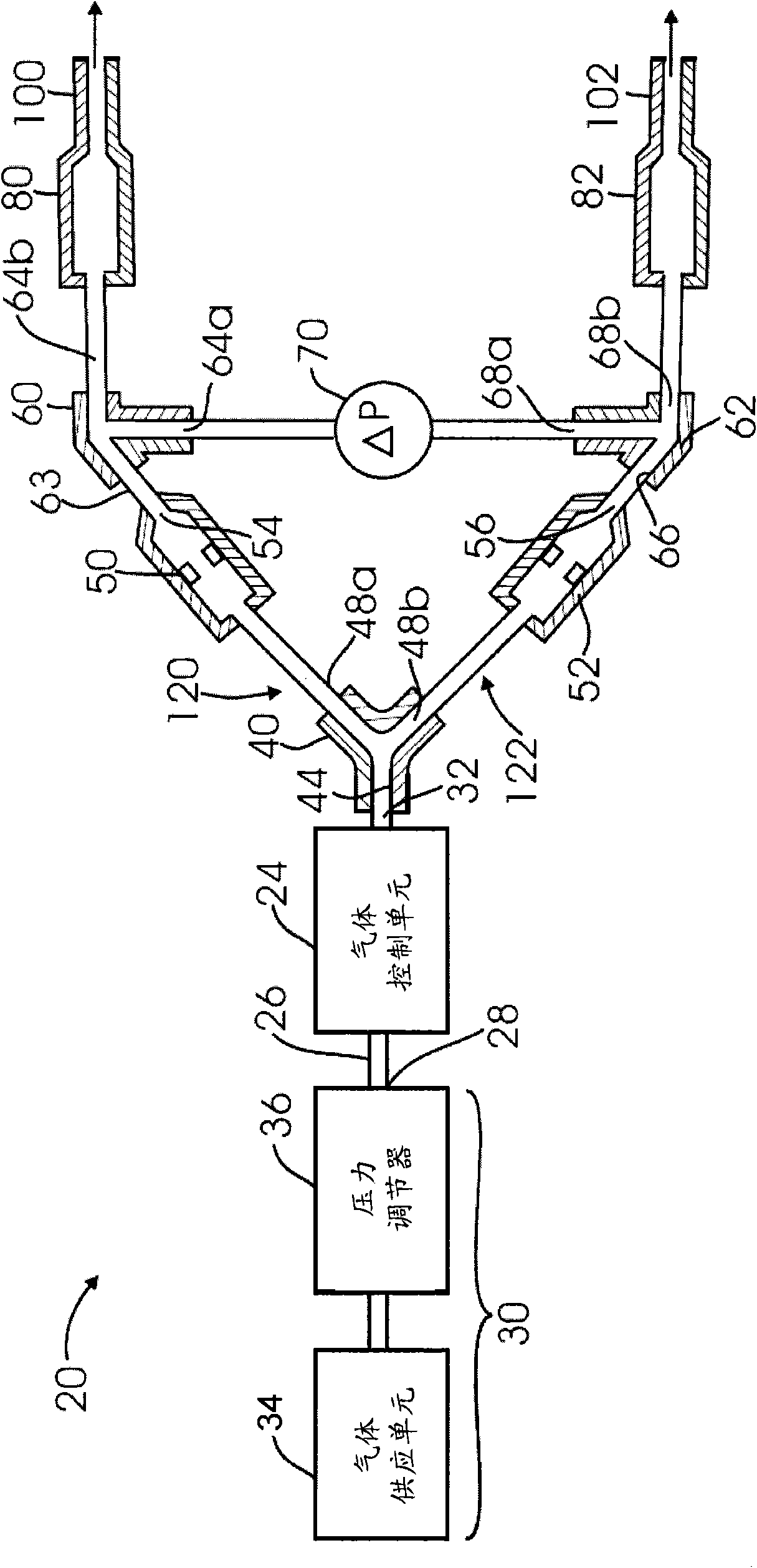
图1A为气体流比较器的实施例的示意剖面图;Figure 1A is a schematic cross-sectional view of an embodiment of a gas flow comparator;
图1B为包含T型气体联结器的分流器的实施例的示意剖面图;1B is a schematic cross-sectional view of an embodiment of a flow splitter comprising a T-shaped gas coupling;
图1C为限流器的实施例的示意剖面图;Figure 1C is a schematic cross-sectional view of an embodiment of a flow restrictor;
图1D为惠斯敦电桥电路的图式;FIG. 1D is a diagram of a Wheatstone bridge circuit;
图2为气体流比较器实施例的透视图;Figure 2 is a perspective view of an embodiment of a gas flow comparator;
图3A为气体流比较器的喷嘴托架的实施例的分解视图;3A is an exploded view of an embodiment of a nozzle holder for a gas flow comparator;
图3B为图3A的组合喷嘴托架的透视图;Figure 3B is a perspective view of the combination nozzle holder of Figure 3A;
图4为气体分配器的实施例的概要底视图;Figure 4 is a schematic bottom view of an embodiment of a gas distributor;
图5为显示用以测试气体分配器的独立喷嘴的相对流速的具有一取样探针及一可调式针阀喷嘴的气体流比较器组态的示意图;5 is a schematic diagram showing the configuration of a gas flow comparator with a sampling probe and an adjustable needle valve nozzle for testing the relative flow rates of individual nozzles of a gas distributor;
图6为显示用以测试装设在一包围室(真空反应室)中的气体分配器的喷嘴数组的比较流速的气体流比较器组态的示意图;6 is a schematic diagram showing the configuration of a gas flow comparator for testing the comparative flow rate of a nozzle array of a gas distributor installed in an enclosed chamber (vacuum reaction chamber);
图7为显示用以测试包含一面板及一阻挡板的气体分配器的喷嘴流速的气体流比较器组态的示意图;7 is a schematic diagram showing a gas flow comparator configuration for testing nozzle flow rates of a gas distributor comprising a panel and a baffle;
图8为使用绝对量测流量计而获得通过二气体分配器的特定喷嘴的流动传导性的二柱状图;Figure 8 is a two histogram of the flow conductance through a particular nozzle of a two gas distributor obtained using an absolute measurement flow meter;
图9为显示藉压力计于电压量测的相对差异的数值图,其是对应于通过气体分配器的不同喷嘴所量测的流速;Figure 9 is a numerical graph showing the relative difference in voltage measurements by manometers, corresponding to flow rates measured through different nozzles of the gas distributor;
图10为一沉积在基材上的氧化硅薄膜的膜厚度变化的等高图;Fig. 10 is a contour map of film thickness variation of a silicon oxide film deposited on a substrate;
图11为流经用于图10的沉积工艺的气体分配器的不同喷嘴的气体流的等高图;以及11 is a contour diagram of gas flow through different nozzles of the gas distributor used in the deposition process of FIG. 10; and
图12为一具有二反应室及一用于控制通过各反应室的气体分配器的工艺气体流速的气体流比较器组态的基材处理设备的示意图。12 is a schematic diagram of a substrate processing apparatus configured with two reaction chambers and a gas flow comparator for controlling the flow rate of process gas through the gas distributor of each reaction chamber.
主要组件符号说明Explanation of main component symbols
20气体流比较器 24气体控制单元20
26(气体)管 28入口26 (gas)
30气体源 31气体联结器30
32出口 33气体阀32
34气体供应器 35气体过滤器34
36压力调节器 37压力显示器36
38流量计 40分流器38
41气体联结器 42中空管41 gas coupling 42 hollow tube
43a-c脚部 44入口端口43a-
46a-c联结端 48a第一输出端口46a-
48b第二输出端口 50(第一)限流器48b second output port 50 (first) current limiter
51a、b端部 52(第二)限流器51a, b end 52 (second) current limiter
53中空管 54、56出口53
55入口 58档板55
59孔洞 60、62第二分流器59
63入口端口 64a、b(第一)输出端口63
66入口端口 68a、b(第二)输出端口66
70压差计 80托架70
82托架 93电压源82
94惠斯敦电桥 95接脚94
96接脚 97、98中点96
99电流计 100、102喷嘴99
101、103源电压端 104容设部101, 103
105a、b孔 106插入件105a,
107肩部 108垫圈107
109内表面 109a、b面板109
110后端部 112环形螺帽110
111凹部 116联结器111
120、122信道 126气体分配器/板120, 122
126a、b气体分配器/板 128a、b数组126a, b gas distributor/
129(第一)管 130探针129 (first)
131(第二)管 132针阀131 (second)
134密封件 135a、b阻挡板134
138包围室 138a、b反应室138
140(基材处理)设备 141气体流控制器140 (substrate processing) equipment 141 gas flow controller
142压力计 144真空泵142
148控制器 150a、b气体管线148
154a、b歧管 158a、b流量调节阀154a,
160a、b基材 162a、b基材支撑座160a,
163a、b间隔控制单元 164a、b温度控制单元163a, b
165a、b排放端口 166a、b排放管线165a,
168共同排放管线 170真空泵168
180a、b气体激发器180a, b gas exciter
具体实施方式 Detailed ways
一气体流比较器20的实施例,如显示于图1A及图2,是经由一压差量测以量测通过多个喷嘴的气体的气体参数差异。所量测的气体参数差异可为例如气体的流速或压力。气体流比较器20包含一安装于气体管26上的气体控制单元24,以设定气体通过气体管26的气体流速率或气体压力。气体管26具有一入口28及一出口32,该入口28连接至一气体源30,且气体是通过该出口32而自气体管26流出。气体源30包括一气体供应单元34(例如一气体加压容器)及一用以控制气体离开气体供应单元的压力的压力调节器36。在一态样中,气体源30设定为在由约50至约150psia的压力提供一气体,例如氮。An embodiment of a
气体控制单元24提供在一选定气体流速或压力的气体至一设备。参考图2,来自气体源(未显示)的气体流经由一气体联结器31进入气体管26。以人工操作在气体管26上的一气体阀33,以设定通过管26的气体流。气体流接着通过气体过滤器35,而气体过滤器35可为传统气体过滤器,如美国乔治亚州亚特兰市McMaster Carr公司可购得者。气体控制单元24可为例如一气体流控制单元或一气体压力调节器。在一态样中,气体控制单元24为一流量计38,例如质流控制器(MFC)或体积流量控制器。气体控制单元24可包含一气体流控制回馈环路,以控制气体通过气体管26的气体流速,其一般已知为一流体控制是质量流量计。在流量计38设定的流速为气体流出管出口32的流速,且质量流量计38监测气体流速,并响应量测的流速以调整一内部或外部阀而获得一气体的实质恒定流速。实质恒定意指流速变化低于5%。气体控制单元24提供一实质恒定气体流速,例如与标称流速差异低于5%的流速。一适当的流量计38为一质流控制器(MFC),为日本京都STE公司MFC型号4400的300sccm氮。气体控制单元24的另一态样为压力控制MFC,如美国麻州威明顿MKS Instruments公司的速率为3000sccm的MFC。另一适当的气体控制单元24可包括美国加州犹耳巴林达的UNIT的MFC。另一气体控制单元24为一压力调节器36,如美国俄亥俄州克里夫兰Parker Hannifin公司的Veriflo分公司的VARIFLOTM压力调节器,或一得自美国俄亥俄州索隆Swagelok公司的压力调节器。一压力显示器37在流量计38后设置以读取供应至气体流比较器20的气体。The
将处于恒定流速及/或压力的气体供应至一主要分流器40,其具有一连接至气体管26的出口32的入口端口44以接收气体。此分流器40将接收到的气体流分流至第一及第二输出端口48a、b。分流器40可将气体流分流为二独立且相等的气体流或依预定比例而分流气体流。在一例示中,分流器40于第一及第二输出端口48a、b间平均将所接收到的气体流进行分流。此可通过将输出端口48a、b定位而对称于入口端口44来达成。在一态样中,主要分流器40包含一T型气体联结器41,如显示于图1B。T型气体联结器41包含一T型中空管42,中空管42的每一脚部43a-c具有一联结端46a-c,其可与一气体管形成气密。一适当的T型联结器为一或
第一及第二限流器50、52为各自连接至第一及第二输出端口48a、b。每一限流器50、52提供一跨越限流器的压降(pressure drop)。由各个限流器50,52所提供的压降基本上相同,但其亦可为不同。在一态样中,第一限流器50具有一限流器出口54,及第二限流器52具有一限流器出口56。限流器50的实施例的横切面如图1C所示,包含一具有限流器入口55及限流器出口54的中空管53,且出口54与入口55是分别位于端部51a、b中。端部51a、b是经成形而与上方气体管53提供一气密封。限流器50更包含一具有孔洞59的档板58,而孔洞59具有一预定大小且位于中空管53之中央部分。中空管53亦可在一收缩段由较大直径缩减至一较小直径(未显示)以提供所欲的限流作用,以替代档板58。另一态样中,限流器50可包含一喷嘴。适合的限流器50、52包括由美国麻州沃桑BIRDPrecision公司取得的Ruby Precision Orifices。The first and second
一对辅助分流器60、62连接至限流器50、52的限流器出口54、56。第一辅助分流器60包含一入口端口63及一对第一输出端口64a、b,而第二辅助分流器62亦具有一入口端口66及一对第二输出端口68a、b。第二分流器60、62亦可包含前述的T型气体联结器41。A pair of
一压差计70是连接跨过辅助分流器60、62的输出端口64a、68a。在一态样中,压差计70适于量测至少1托耳(Torr),或甚至至少5托耳,或甚至50托耳的压力。压差计70的精确度依通过气体流比较器20的气体的压力或流速而定。例如,一具有压力范围量测能力为50托耳的压差计70所具有的精确度为至少约±0.15托耳;反的,能量测一压力范围为1托耳的压差计70具有的精确度为0.005托耳。一适当的压差计70为购自MKS Instruments公司的MKS 223B压差传感器。压差计70通过在前向或反向的膜片位移而操作,膜片位移会对应于所量测的压差而产生正或负电压。A
第一及第二喷嘴托架80、82是连接至辅助分流器60、62的一对输出端口64b、68b上。可连接喷嘴托架80、82以供给气体至喷嘴106、102,而用于量测经由喷嘴的比较性流速。例如,喷嘴托架80、82可连接至第一参考喷嘴100及一用以测试相对于参考喷嘴的流速的第二测试喷嘴102;或可互相比较经由二喷嘴106、102的相对流速。The first and
为比较经由二喷嘴106、102的流速,喷嘴106、102是附接至喷嘴托架80、82。在喷嘴托架82中安装喷嘴102的分解视图是显示于图3A。喷嘴102滑入一聚合物插入件121的凹陷容设部104中,以致喷嘴102的呈角度的肩部107接触聚合物插入件121的呈角度的内表面109。一铁氟龙垫圈108安装于喷嘴102之后端部110以形成一密封垫片。插入件106与喷嘴102的组件接着插入环形螺帽112的配合凹部111中。此组件然后螺锁至基部联结器116,并以手压合以形成一良好密合。喷嘴托架82与往外延伸的喷嘴102的组合,如显示于图3B,是扣合装配至气体流比较器20的气体联结器或气体管。当以另一测试喷嘴替换喷嘴102时,喷嘴托架82的配件需以异丙醇擦拭干净。To compare the flow rates through the two
在操作中,气体供应器34及气体控制单元24为用以提供恒定流速或恒定压力的气体至气体流比较器20的气体管26的入口28。在一态样中,设定压力调节器36以提供在例如约10~约150psig或甚至40psig的恒定压力的气体至具有16密耳(mils)直径的喷嘴,且设定流量计38以提供约100~3000sccm的流速,及在一态样中为300sccm。然而,当量测大量喷嘴102时,则设定的气体流速或气体压力较大,例如具有数千个喷嘴的气体分配器的扇形喷嘴102,则流速可设定至约80slm~约140slm,或甚至约100slm~约120slm。In operation, the
压差计70在每一测试阶段开始时归零。提供恒定流速或恒定压力的气体至主要分流器40,而分流器40将气体导引通过具有第一及第二限流器50、52的独立的第一及第二流体信道120、122。气体在离开限流器50、52的出口54、56之后,则流经第一及第二喷嘴106、102,且第一及第二喷嘴106、102的至少其中之一者会经过测试。通过喷嘴106、102的任何气体流速的差异,或是跨越喷嘴106、102的压降会造成压差计70呈现压差,且该压差是与气体通过喷嘴106、102的流速的变化成比例。量测喷嘴性能的传统方法为直接使用一质量流量计量测通过喷嘴的流量,且此流量量测准确度受通过喷嘴的总流量的量测精确度的限制。相反的,气体流比较器20允许经由喷嘴106、102的标称流速的约±1.5%内的流量变化的量测。喷嘴流速是量测为通过在二喷嘴106、102及上游压力间的压差的喷嘴阻力的改变百分比。通过量测在阻力的差异,气体流比较器20可产生一流量量测的精确度,其至少为一优于传统流量测试装置的大小等级。The
气体流比较器20的操作可以参照图1D所示的惠斯敦电桥(Wheatstone Bridge)94电路来解释。一惠斯敦电桥94是用于量测一未知电阻器的未知电阻值,其是通过平衡桥电路的二接脚,其中一接脚包括一未知电阻器,并由电压源93供电。在惠斯敦电桥94中,Rx表示未知的电阻器;及R1、R2与R3表示具有已知电阻值的电阻器,而R2的电阻为可调整的。若在第一接脚95的二己知电阻器比例(R2/R1)相等于在第二接脚96的二未知电阻器比例(Rx/R3),则在二中点97、98间的电压为零且没有电流流过中点97、98。变化R2直至达到此一状况。电流方向说明R2为过高或过低。可完成侦测零电流至非常高的精确性。因此,若R1、R2及R3为已知至一高精准的值,则随着在RX的小改变而中断平衡,Rx可量测至一相同精准值,且易于被侦测。当惠斯敦电桥94平衡时,其意指通过电流计99的电流(Rg)等于零,在源电压端101、103间的电路的等效电阻(RE)是将R1+R2与R3+R4做对比来决定的,如下:The operation of the
RE={(R1+R2)·(R3+Rx)}/{R1+R2+R3+R4}R E ={(R 1 +R 2 )·(R 3 +R x )}/{R 1 +R 2 +R 3 +R 4 }
亦可替换的,若R1、R2、及R3为己知,但R2为不可调整,则可利用Kirchhoff电路定律(亦称为Kirchhoff法则)并使用流经电流计99的电压或电流来计算Rx值,。Alternatively, if R 1 , R 2 , and R 3 are known, but R 2 is not adjustable, one can use Kirchhoff's circuit laws (also known as Kirchhoff's law) and use the voltage or current flowing through the ammeter 99 to calculate the R x value, .
在显示于图1A及图2的气体流比较器20中,限流器50、52及喷嘴106、102为表示或相当于图1D惠斯敦电桥94的固定电阻器、可调式电阻器,及未知电阻器。针对气体流比较器20,限流器50、52分别表示固定流阻R1及R2,其值相等,故R1=R2=Ru。再者,喷嘴106、102分别表示流阻R3及R4,其在值上亦应相等,故R3=R4=Rd=k Ru,其中k>1。然而,若R4相对于R3而改变ΔR,则压差为:In the
ΔP=Q{ΔR/[2(1+k)+ΔR/Ru]}ΔP=Q{ΔR/[2(1+k)+ΔR/R u ]}
当此等式为线性,ΔPαΔR,且因此由气体流比较器20量测的压差与二喷嘴106、102的流阻为成比例的。When this equation is linear, ΔPαΔR, and thus the differential pressure measured by the
在一态样中,亦可使用校正喷嘴的套件,以辨识气体流比较器20处于适当的操作状态。此套件可具有不同型式喷嘴106、102,或是相同型式的多重喷嘴(意即具有相同孔径大小)。例如,喷嘴套件可含有具有开口大小为约0.013~至约0.0210英寸的喷嘴,是以0.0005英寸增量。校正喷嘴套件亦可为日本Kyocera公司的陶瓷喷嘴,其具有一受控制的孔径大小。套件可助于校正测试用的喷嘴以决定测试喷嘴的实际流速。In one aspect, a calibration nozzle kit may also be used to identify that the
在另一态样中,气体流比较器20适于连接至气体分配器126的喷嘴102,其中气体分配器126是用于分布工艺气体至基材处理反应室。气体分配器126,一态样为显示于图4,包含多个间隔设置的喷嘴102,例如喷嘴102可共计约100至约10,000个,或甚至约1000至约6000个。图5显示一适用于测试气体分配器126的独立喷嘴102流速的组态。在此组态中,喷嘴托架80包含一用于取样气体分配器126的每一独立喷嘴102流速的取样探针130。在一型式的取样操作中,取样探针130为置于一特定喷嘴102的上方以量测一独立喷嘴相对于参考喷嘴100的相对流速。喷嘴托架82为连接至参考喷嘴100,其可为一固定大小喷嘴,或是可调式喷嘴(其开口大小可利用可调式针阀132做调整),如显示于图5。在后者的例子中,针阀132是设定以配合在气体分配器126上单一选定喷嘴102所量测的传导率,且然后探针130于喷嘴之间移动以检查流经每一喷嘴的流速。此方法允许确认通过气体分配器126的喷嘴102的气体流速均一性。在此组态中,气体控制单元24包含一流量计38,其包括一设定以提供流速为1000sccm的氮气的质量流量控制器。在气体流通道120、122的限流器50、52分别为具有孔径为约0.35mm(0.014in)的喷嘴。压差计70具有1托耳的压差量测范围。In another aspect, the
在一态样中,取样探针130包含具有第一直径的第一管129,第一管129是连接至具有第二直径的第二管131,其中第二直径小于第一直径。例如,第一管129可具有约6.4mm(0.25英寸)的第一直径,且容设一具有第二较小直径3.2mm(0.125英寸)的第二管131。管129、131可为塑料管。一O型环密封件134装设于取样探针130的第二管131的开口周围以形成密封,且O型环密封件134可为例如具有直径为约3.2mm(0.125英寸)的内孔及外部尺寸为约6.4mm(0.125英寸)或更大的的硅胶环。在一态样中,硅胶环具有约20的硬度量测值(Durometer hardnessmeasurement)。硅胶环例如为购自美国乔治亚州亚特兰大McMaster-Carr公司的20硬度超软硅胶。在另一态样中,取样探针130包含一VCO配件,其适于与平坦表面形成一气密封,并具有一含沟槽的平坦端,且一O型环垫圈是容设于沟槽内。一适当的O型环可具有约3.2mm(0.125英寸)直径。供应至气体流比较器20的气体可为氮。In one aspect, the
在另一量测方法中,使用气体流比较器20以量测安装在包围室138中的单一气体分配器126的喷嘴102的二或多个数组128a、b的相对气体流传导性,如显示于图6,该包围室138可为基材处理设备140的真空反应室或工艺反应室。在此组态中,一喷嘴托架80是适于使气体通过单一喷嘴102,或通过气体分配器126(例如显示于图4)的喷嘴102的一选定数组128a、b并同时密封住气体分配器126的其它剩余孔。包围室138具有一压力计142以量测反应室中的压力,其为例如购自前述的MKSInstruments公司的BARATRON压力计,其具有一膜片且可量测高达100托耳的压力。包围室138亦具有一真空泵144,如一机械位移真空泵,例如购自英国Edwards BOC公司的QDP-80。喷嘴托架80、82是通过在二扇形周围形成气密以适于量测二数组128a、b的相对传导性,其中二数组128a、b包含一气体分配器126的一扇形喷嘴102。亦可使用一夹具(未显示)以封合其它不会经过量测的气体分配器126的喷嘴102,以允许仅量测通过开启喷嘴102的气体流速。夹具为一简单的密封装置以覆盖喷嘴102。通过量测通过在气体分配器126的喷嘴102的独立数组128a、b的平均流速,可比较通过不同扇形或区域的流速。此可用于做为一定性测试以除去具有不均匀的喷嘴102的数组128a、b的气体分配器126,而此不均匀数组128a、b是归因于不良机器制成或其它制造的喷嘴。In another measurement method, a
可与气体流比较器20使用的另一量测方法包含量测二气体分配器126a、b的喷嘴的气体流传导率,各个气体分配器126a、b包含一面板109a、b,且各面板109a、b包括一输入气体歧管154a、b,各面板109a、b分别面向具有大量喷嘴106、102的阻挡板135a、b,且将气体排放至一无尘室环境,如显示于图7。通过各自安装的板126a、b的喷嘴106、102(或如图6所示的单一板126的喷嘴102)的流体的总流量及均一性应相同,不然的话,在使用该些气体分配器的基材处理期间会产生不均匀的操作。一适于比较通过二板126a、b的总流速的组态包含安装气体流比较器20,以使每一喷嘴托架80、82与喷嘴102(图5)、或气体分配器126a、b的喷嘴102的数组128a、b(图6)连接。气体流比较器20通过量测气体分配器126a、b的二面板109a、b的背侧孔105a、b与气体源30的上游或输入气体压力之间的压差以量测流动阻力或流动传导性的差异百分比。通过量测流动阻力的差异,此气体流比较器20可用以获得精确的流速以及流量资料的一致,其可用于改进双反应室138a、b的气体分配器126a、b的配合。Another measurement method that can be used with the
一适于比较通过二板126a、b的总流速的组态包含安装气体流比较器20,以使每一喷嘴托架80、82与每一反应室138a、b的输入气体歧管154a、b连接,而歧管154a、b是供应各自的气体分配器126a、b。在此组态中,气体流比较器20通过量测二歧管154a、b及气体源30的上游或输入气体压力之间的压差以量测流动阻力或流动传导性的差异百分比。通过量测流动阻力的差异,此气体流比较器20可用以获得精确的流速,以及流量资料的一致,其可用于改进双反应室138a、b的气体分配器126a、b的配合。One configuration suitable for comparing the total flow rates through the two
气体分配器126的不同喷嘴102之间,或是不同气体分配器126a、b之间会发生的绝对流速变化,如使用传统流量量测设备量测者为显示于图8。通过二不同气体分配器126a、b的特定喷嘴102所获得的流体气导率为提供于图上。第一板126a具有大小为0.6mm(0.024英寸)的喷嘴102及第二板126b具有大小为0.7mm(0.028英寸)的喷嘴。虽然通过喷嘴的流速在各个板是相当不同,在第一板126a是由120至125sccm间变化,而第二板126b为在156至167sccm间变化,当关闭在二板126a、b中特定的喷嘴102的少于1%,板126a、b提供平衡的流速。比较包含板126a、b的扇形喷嘴的二对等数组128亦导致在扇形间的流速比1%更接近的一致性。然而,通过不同喷嘴102的不同流速可在基材上产生显著不同的沉积或蚀刻速率。因此,此说明气体分配器板126的独立喷嘴102的流量测量对量测为重要且可实质地改变。在此实施例中,流量量测装置为美国亚历桑纳州坦帕市DH Instruments公司的MOLBLOC。The absolute flow rate variation that occurs between
一经由气体分配器板126的独立喷嘴102取样的流速的相对差异变化图,藉压差计70量测而以伏特表示的,为显示于图9。在此图中,是显示气体分配器126的不同喷嘴,+0.43V相当于通过喷嘴的261sccm流速,而-0.80V相当于267sccm。对特定喷嘴102量测的差异流速的范围以制成一流量等高图(flow contour map),其与在基材160上处理的材料的厚度或其它表面特性的均质性图表相关。通过使用流量计以进行相对于绝对流量量测的压差量测,可在流速量测上获得较高的精确度。在一实施例中,当压差计70的分辨率为1mV时,流经具有阻挡器(blocker)的气体分配器126的140slm N2会造成每一阻挡孔8mV的变化。即使因流量变化,此可提供在板126中由多于一千个喷嘴覆盖的单一孔的侦测能力。因而在一传统质量流量计提供精确度仅至约0.5%的绝对流量量测;本发明方法可轻易的获得相较于参考喷嘴102的优于0.1%的流量精确度。A graph of the relative difference in flow rates sampled through the
在一工艺反应室中使用硅烷气体而沉积于基材160上的氧化硅薄膜的厚度可量测及显示于图10的等高图。薄膜厚度全面差异在约


在另一量测组态中,可使用自动流量均量制图装置以量测气体分配器126的不同喷嘴102的流量均一性。例如,此装置包括一气体流比较器及X-Y-Z作动台,以移动取样探针130横跨板126至不同喷嘴以测试每一喷嘴102。此测试装置允许针对各个新的气体分配器126的完全流量等高图的量测。In another measurement configuration, an automatic flow uniformity mapping device may be used to measure the flow uniformity of
一基材处理设备140亦可包含一气体流控制器141以控制通过喷嘴102的多个气体流速以导入工艺气体至多个基材处理反应室138a、b中。在一态样中,气体流控制器141包含一气体流比较器20,且用以自动调整工艺气体至反应室138a、b的流速。工艺气体可由一远程等离子源激发,如由美国加州尔湾市Astron公司制造的RPS源。每一反应室138a、b包含一输入气体管线150a、b以供给工艺气体至气体歧管154a、b,其接着将气体供应至一气体分配器126a、b。在操作中,工艺气体通过气体流比较器20的第一及第二限流器50、52及喷嘴托架80、82,且喷嘴托架80、82连接至供应反应室138a、b中的气体分配器126a、b的输入气体管线150a、b,此造成气体流比较器20的压差计70指示一与流经喷嘴102的气体流速中的变化呈比例的压差。A
在操作中,一压差讯号由压差计70送至一控制器148,其相应于讯号而调整连接至基材工艺反应室138a、b的输入气体管线150a、b的流量调节阀158a、b,以形成一密闭回路控制系统。流量调节阀158a、b的一端各自分别连接至辅助分流器60、62的输出端口64b、68b,而另一端则连接至反应室138a、b的输入气体管线150a、b,并供应反应室138a、b中的气体分配器126a、b。流量调节阀158a、b响应由控制器148接收的流量控制讯号以控制通过输入气体管线150a、b的工艺气体流量。在另一显示的态样中,压差计70置于流量调节阀158a、b之前。因为压差计70具有一高流量阻抗,故压差计70在工艺气体通过流量调节阀158a、b及气体管线150a、b的流速上具有最小的影响。因此,压差计亦可置于沿着气体供应信道的其它位置。In operation, a differential pressure signal is sent from the
反应室138a、b亦可用于做为真空测试设备以测试经板126a、b的流量差的包围室138。压差计测量施用至输入管的气体压差,而输入管是供应工艺气体至每一反应室138a、b。The
在一态样中,流量调节阀158a、b是经机械化以允许相应于压差计70的压差讯号而进行流量调整自动化。例如,流量调节阀158a、b可电力驱动或人工驱动。在一实施例中,二流量调节阀158a、b是经调整直至达到所欲设定点为止,而此设定点为对应于得自压差计70的0托耳的量测压差的讯号。相似地,例如当需要不对等的流速至各气体分配器126a、b时,则所欲的设定点为-2托耳,阀158a、b可依此调节。此容许在不同工艺配方(process recipe)中设定压差,且在设备140操作期间自动执行此压差。事实上,零压差不能提供最好的结果,但可造成在二气体管线150a、b间的平均分流。小至0.1毫托耳的背压差(differential backpressure)的差异可有利地用于解析低至总流速的0.1%的流量差,或甚至流速的0.01%的流量差,其与传统流量控制计相反,传统流量控制计只能提供总流速的约1%的流量差的解析能力,此代表10倍佳的流量解析能力。In one aspect, the
设备140可为例如得自美国加州APPlied Materials公司的具有双反应室138a、b的ProducerTM。此双处理反应室138a、b彼此上下设置,且每一反应室提供处理一或多个基材160的能力。反应室138a、b的多个可能应用中的一者为,用于以硅烷气体沉积氧化硅薄膜于基材160(包括硅晶片)上,晶片尺寸为300mm。在一实施例中,反应室138a、b包括一致的组件以进行相同的半导体工艺操作,或是相同的工艺操作组。相同的组态可使反应室138a、b同时进行相同的化学气相沉积操作,其中绝缘或传导材料是沉积于放置在各反应室138a、b的晶片上。在另一实施例中,相同的半导体工艺反应室138a、b为用以蚀刻基材160,如硅晶片,一般是经由在晶片表面上的光阻或其它型式屏蔽层的开口。当然,在反应室138a、b中可进行任何合宜的半导体操作,如等离子气相沉积、外延层沉积,或甚至蚀刻工艺如PAS蚀刻、回蚀(etch back)、或间隙壁蚀刻工艺。如下文将描述,此操作的选择在本文描述的系统背景中为可随意的。
基材160a、b例如硅晶片或其它型式的半导体晶片,是运送至各反应室138a、b以放置于一基材支撑座162a、b上。每一基材支撑座162a、b可包括一温度控制单元164a、b,其含有一加热器以加热基材160a、b。若仅要使通过反应室138a、b的气体流均等,则不需要使薄膜沉积速率均等或是在反应室138a、b中产生相同工艺结果。例如,仍会因为其它因素而使薄膜厚度具有变化,例如温度差异及在气体分配器126a、b与基材160a、b间的间隔。晶片温度是通过使用温度控制单元164a、b来改变基材支撑座162a、b的温度而调整的。并利用连接至基材支撑座162a、b之间隔控制单元163a、b来调整上述间隔。
每一反应室138a、b具有一排放端口165a、b,其连接至各自的排放管线166a、b,而排放管线166a、b是接合以形成一共同排放管线168,其导引至一真空泵170。在操作中,反应室138a、b可使用一泵以抽吸至低压力,如真空泵,且例如一粗抽泵、涡轮分子泵及其它泵的组合,以在反应室138a、b中提供所欲的压力。在排放管线166a、b中设置有下游节流阀以控制反应室138a、b中的气体压力。Each
当用于等离子辅助工艺时,反应室138a、b亦可具有气体激发器180a、b。气体激发器180a、b可为在反应室138a、b内的电极、反应室外侧的感应线圈、或远程等离子源(如一微波或RF源)。气体激发器180a、b可用以设定施用以产生及维持在反应室138a、b内的等离子或激发气体物种的能量。When used in a plasma-assisted process, the
前文已提供本发明的不同实施例的描述以用于了解本发明。说明部分并非用以彻底详尽说明或限制本发明至描述的较佳态样。例如,本发明的实施例可用于配合至少三反应室。再者,在多个反应室系统的至少一反应室可建构为同时处理至少一晶片。据此,在前述示中的多种润饰及变化为可行的。The foregoing descriptions of various embodiments of the present invention have been provided for understanding of the present invention. The descriptive section is not intended to be exhaustive or to limit the invention to the preferred aspects described. For example, embodiments of the present invention may be used to accommodate at least three reaction chambers. Furthermore, at least one chamber in a multiple chamber system can be configured to process at least one wafer simultaneously. Accordingly, various modifications and variations of the foregoing illustrations are possible.
Claims (14)
Applications Claiming Priority (3)
| Application Number | Priority Date | Filing Date | Title |
|---|---|---|---|
| US81044606P | 2006-06-02 | 2006-06-02 | |
| US60/810,446 | 2006-06-02 | ||
| PCT/US2007/012348 WO2007142850A2 (en) | 2006-06-02 | 2007-05-22 | Gas flow control by differential pressure measurements |
Publications (2)
| Publication Number | Publication Date |
|---|---|
| CN101460659A CN101460659A (en) | 2009-06-17 |
| CN101460659B true CN101460659B (en) | 2011-12-07 |
Family
ID=38670684
Family Applications (1)
| Application Number | Title | Priority Date | Filing Date |
|---|---|---|---|
| CN2007800203964A Expired - Fee Related CN101460659B (en) | 2006-06-02 | 2007-05-22 | Gas flow control by differential pressure measurements |
Country Status (5)
| Country | Link |
|---|---|
| US (1) | US20080000530A1 (en) |
| KR (1) | KR101501426B1 (en) |
| CN (1) | CN101460659B (en) |
| TW (1) | TWI418963B (en) |
| WO (1) | WO2007142850A2 (en) |
Families Citing this family (27)
| Publication number | Priority date | Publication date | Assignee | Title |
|---|---|---|---|---|
| JP4550507B2 (en) * | 2004-07-26 | 2010-09-22 | 株式会社日立ハイテクノロジーズ | Plasma processing equipment |
| US8216374B2 (en) * | 2005-12-22 | 2012-07-10 | Applied Materials, Inc. | Gas coupler for substrate processing chamber |
| US7743670B2 (en) * | 2006-08-14 | 2010-06-29 | Applied Materials, Inc. | Method and apparatus for gas flow measurement |
| JP5243089B2 (en) * | 2008-04-09 | 2013-07-24 | 東京エレクトロン株式会社 | Seal structure of plasma processing apparatus, sealing method, and plasma processing apparatus |
| EP2335126A1 (en) * | 2008-10-14 | 2011-06-22 | Circor Instrumentation Technologies, Inc. | Method and apparatus for low powered and/or high pressure flow control |
| US8043434B2 (en) * | 2008-10-23 | 2011-10-25 | Lam Research Corporation | Method and apparatus for removing photoresist |
| US8588733B2 (en) | 2009-11-11 | 2013-11-19 | Lifestream Corporation | Wireless device emergency services connection and panic button, with crime and safety information system |
| US9127361B2 (en) * | 2009-12-07 | 2015-09-08 | Mks Instruments, Inc. | Methods of and apparatus for controlling pressure in multiple zones of a process tool |
| US20130255784A1 (en) * | 2012-03-30 | 2013-10-03 | Applied Materials, Inc. | Gas delivery systems and methods of use thereof |
| CN103928284B (en) * | 2013-01-15 | 2016-04-06 | 中微半导体设备(上海)有限公司 | The method of testing of charge delivery mechanism and gas diverter thereof |
| CN103966573B (en) * | 2013-01-29 | 2016-12-28 | 无锡华润上华科技有限公司 | Gas reaction device and method for PECVD thin film deposition |
| CN104167345B (en) * | 2013-05-17 | 2016-08-24 | 中微半导体设备(上海)有限公司 | Plasma treatment appts and air transporting arrangement, gas switching method |
| EP2833231B1 (en) * | 2013-07-29 | 2017-10-04 | Honeywell Technologies Sarl | Gas burner having a servo gas system with a hydraulic Wheatstone-bridge controlling an electric fuel supply valve, and method of operating such a gas burner |
| EP3686565A1 (en) * | 2015-02-05 | 2020-07-29 | CiDRA Corporate Services, Inc. | Techniques to determine a fluid flow characteristic in a channelizing process flowstream, by bifurcating the flowstream or inducing a standing wave therein |
| JP6910652B2 (en) * | 2016-04-28 | 2021-07-28 | 株式会社フジキン | Control method of fluid control system and fluid control device |
| US20180046206A1 (en) * | 2016-08-13 | 2018-02-15 | Applied Materials, Inc. | Method and apparatus for controlling gas flow to a process chamber |
| JP6626800B2 (en) * | 2016-08-19 | 2019-12-25 | 東京エレクトロン株式会社 | Method for inspecting shower plate of plasma processing apparatus |
| JP6913498B2 (en) * | 2017-04-18 | 2021-08-04 | 東京エレクトロン株式会社 | Method of obtaining the output flow rate of the flow rate controller and method of processing the object to be processed |
| US10967084B2 (en) * | 2017-12-15 | 2021-04-06 | Asp Global Manufacturing Gmbh | Flow restrictor |
| US10845263B2 (en) | 2018-04-17 | 2020-11-24 | Mks Instruments, Inc. | Thermal conductivity gauge |
| CN111430213B (en) * | 2020-05-07 | 2025-05-30 | 上海邦芯半导体科技有限公司 | Air intake structure and plasma etching equipment |
| US12266550B2 (en) * | 2020-07-19 | 2025-04-01 | Applied Materials, Inc. | Multiple process semiconductor processing system |
| US11555730B2 (en) | 2020-10-09 | 2023-01-17 | Applied Materials, Inc. | In-situ method and apparatus for measuring fluid resistivity |
| CN112879812B (en) * | 2021-01-13 | 2024-04-12 | 山东智化普新材料有限公司 | Liquid separating and adjusting device capable of automatically adjusting flow speed according to water flow |
| CN115386859A (en) * | 2022-08-16 | 2022-11-25 | 拓荆科技(上海)有限公司 | Current limiting assembly and process cavity |
| US12123794B2 (en) | 2022-10-11 | 2024-10-22 | Mks Instruments, Inc. | Pirani gauge with model of power dissipation |
| CN115537780B (en) * | 2022-10-20 | 2024-07-16 | 季华实验室 | A gas flotation drive device, system and method for a reaction chamber |
Citations (3)
| Publication number | Priority date | Publication date | Assignee | Title |
|---|---|---|---|---|
| US4550592A (en) * | 1984-05-07 | 1985-11-05 | Dechape Michel L | Pneumatic gauging circuit |
| US4953388A (en) * | 1989-01-25 | 1990-09-04 | The Perkin-Elmer Corporation | Air gauge sensor |
| US6843882B2 (en) * | 2002-07-15 | 2005-01-18 | Applied Materials, Inc. | Gas flow control in a wafer processing system having multiple chambers for performing same process |
Family Cites Families (90)
| Publication number | Priority date | Publication date | Assignee | Title |
|---|---|---|---|---|
| NL73735C (en) * | 1949-06-30 | |||
| US4282267A (en) * | 1979-09-20 | 1981-08-04 | Western Electric Co., Inc. | Methods and apparatus for generating plasmas |
| JPS5782955A (en) * | 1980-11-12 | 1982-05-24 | Hitachi Ltd | Microwave plasma generating apparatus |
| US4538449A (en) * | 1982-11-22 | 1985-09-03 | Meseltron S.A. | Pneumatic measuring device for measuring workpiece dimension |
| AU544534B2 (en) * | 1983-06-14 | 1985-06-06 | Toyota Jidosha Kabushiki Kaisha | Plasma coating |
| JPS6074626A (en) * | 1983-09-30 | 1985-04-26 | Fujitsu Ltd | Device for plasma treatment |
| GB8516537D0 (en) * | 1985-06-29 | 1985-07-31 | Standard Telephones Cables Ltd | Pulsed plasma apparatus |
| US4692343A (en) * | 1985-08-05 | 1987-09-08 | Spectrum Cvd, Inc. | Plasma enhanced CVD |
| JPH0740566B2 (en) * | 1986-02-04 | 1995-05-01 | 株式会社日立製作所 | Plasma processing method and apparatus |
| US4863561A (en) * | 1986-12-09 | 1989-09-05 | Texas Instruments Incorporated | Method and apparatus for cleaning integrated circuit wafers |
| US5158644A (en) * | 1986-12-19 | 1992-10-27 | Applied Materials, Inc. | Reactor chamber self-cleaning process |
| US4867841A (en) * | 1987-07-16 | 1989-09-19 | Texas Instruments Incorporated | Method for etch of polysilicon film |
| US4818326A (en) * | 1987-07-16 | 1989-04-04 | Texas Instruments Incorporated | Processing apparatus |
| KR920002864B1 (en) * | 1987-07-20 | 1992-04-06 | 가부시기가이샤 히다찌세이사꾸쇼 | Apparatus for treating matrial by using plasma |
| US5062386A (en) * | 1987-07-27 | 1991-11-05 | Epitaxy Systems, Inc. | Induction heated pancake epitaxial reactor |
| JPH0225577A (en) * | 1988-07-15 | 1990-01-29 | Mitsubishi Electric Corp | Thin film forming device |
| JPH02150040A (en) * | 1988-11-30 | 1990-06-08 | Fujitsu Ltd | Vapor growth apparatus |
| US5084126A (en) * | 1988-12-29 | 1992-01-28 | Texas Instruments Incorporated | Method and apparatus for uniform flow distribution in plasma reactors |
| US5002632A (en) * | 1989-11-22 | 1991-03-26 | Texas Instruments Incorporated | Method and apparatus for etching semiconductor materials |
| US5163232A (en) * | 1990-02-16 | 1992-11-17 | Texas Instruments Incorporated | Semiconductor lead planarity checker |
| US5269847A (en) * | 1990-08-23 | 1993-12-14 | Applied Materials, Inc. | Variable rate distribution gas flow reaction chamber |
| US5220515A (en) * | 1991-04-22 | 1993-06-15 | Applied Materials, Inc. | Flow verification for process gas in a wafer processing system apparatus and method |
| FR2678367B1 (en) * | 1991-06-26 | 1993-10-22 | Normandie Ateliers | PNEUMATIC DIMENSIONAL MEASURING DEVICE. |
| JP3253675B2 (en) * | 1991-07-04 | 2002-02-04 | 株式会社東芝 | Charged beam irradiation apparatus and method |
| JP3252330B2 (en) * | 1991-09-20 | 2002-02-04 | 東芝セラミックス株式会社 | Electrode plate for plasma etching |
| JPH05206069A (en) * | 1992-01-29 | 1993-08-13 | Fujitsu Ltd | Plasma etching method and plasma etching device |
| US5282899A (en) * | 1992-06-10 | 1994-02-01 | Ruxam, Inc. | Apparatus for the production of a dissociated atomic particle flow |
| EP0647163B1 (en) * | 1992-06-22 | 1998-09-09 | Lam Research Corporation | A plasma cleaning method for removing residues in a plasma treatment chamber |
| JP3227522B2 (en) * | 1992-10-20 | 2001-11-12 | 株式会社日立製作所 | Microwave plasma processing method and apparatus |
| US5413954A (en) * | 1992-11-10 | 1995-05-09 | At&T Bell Laboratories | Method of making a silicon-based device comprising surface plasma cleaning |
| US5997950A (en) * | 1992-12-22 | 1999-12-07 | Applied Materials, Inc. | Substrate having uniform tungsten silicide film and method of manufacture |
| US5444217A (en) * | 1993-01-21 | 1995-08-22 | Moore Epitaxial Inc. | Rapid thermal processing apparatus for processing semiconductor wafers |
| KR200146659Y1 (en) * | 1993-02-22 | 1999-06-15 | 구본준 | Vent apparatus of chamber of vacuum system for semiconductor fabrication |
| US5487785A (en) * | 1993-03-26 | 1996-01-30 | Tokyo Electron Kabushiki Kaisha | Plasma treatment apparatus |
| US5614055A (en) * | 1993-08-27 | 1997-03-25 | Applied Materials, Inc. | High density plasma CVD and etching reactor |
| US5382316A (en) * | 1993-10-29 | 1995-01-17 | Applied Materials, Inc. | Process for simultaneous removal of photoresist and polysilicon/polycide etch residues from an integrated circuit structure |
| US5798016A (en) * | 1994-03-08 | 1998-08-25 | International Business Machines Corporation | Apparatus for hot wall reactive ion etching using a dielectric or metallic liner with temperature control to achieve process stability |
| US5522934A (en) * | 1994-04-26 | 1996-06-04 | Tokyo Electron Limited | Plasma processing apparatus using vertical gas inlets one on top of another |
| GB9410567D0 (en) * | 1994-05-26 | 1994-07-13 | Philips Electronics Uk Ltd | Plasma treatment and apparatus in electronic device manufacture |
| US5665640A (en) * | 1994-06-03 | 1997-09-09 | Sony Corporation | Method for producing titanium-containing thin films by low temperature plasma-enhanced chemical vapor deposition using a rotating susceptor reactor |
| US5558717A (en) * | 1994-11-30 | 1996-09-24 | Applied Materials | CVD Processing chamber |
| JPH08255795A (en) * | 1995-03-15 | 1996-10-01 | Sony Corp | Semiconductor manufacturing method and device |
| US5556521A (en) * | 1995-03-24 | 1996-09-17 | Sony Corporation | Sputter etching apparatus with plasma source having a dielectric pocket and contoured plasma source |
| US5683517A (en) * | 1995-06-07 | 1997-11-04 | Applied Materials, Inc. | Plasma reactor with programmable reactant gas distribution |
| US6045618A (en) * | 1995-09-25 | 2000-04-04 | Applied Materials, Inc. | Microwave apparatus for in-situ vacuum line cleaning for substrate processing equipment |
| US5772771A (en) * | 1995-12-13 | 1998-06-30 | Applied Materials, Inc. | Deposition chamber for improved deposition thickness uniformity |
| US5767628A (en) * | 1995-12-20 | 1998-06-16 | International Business Machines Corporation | Helicon plasma processing tool utilizing a ferromagnetic induction coil with an internal cooling channel |
| US5683548A (en) * | 1996-02-22 | 1997-11-04 | Motorola, Inc. | Inductively coupled plasma reactor and process |
| JP2867946B2 (en) * | 1996-03-13 | 1999-03-10 | 日本電気株式会社 | Vapor phase growth equipment |
| US5976993A (en) * | 1996-03-28 | 1999-11-02 | Applied Materials, Inc. | Method for reducing the intrinsic stress of high density plasma films |
| US6170428B1 (en) * | 1996-07-15 | 2001-01-09 | Applied Materials, Inc. | Symmetric tunable inductively coupled HDP-CVD reactor |
| US5653808A (en) * | 1996-08-07 | 1997-08-05 | Macleish; Joseph H. | Gas injection system for CVD reactors |
| US5777245A (en) * | 1996-09-13 | 1998-07-07 | Applied Materials, Inc. | Particle dispersing system and method for testing semiconductor manufacturing equipment |
| KR100242982B1 (en) * | 1996-10-17 | 2000-02-01 | 김영환 | Gas supply apparatus of semiconductor device |
| US5939831A (en) * | 1996-11-13 | 1999-08-17 | Applied Materials, Inc. | Methods and apparatus for pre-stabilized plasma generation for microwave clean applications |
| US6125859A (en) * | 1997-03-05 | 2000-10-03 | Applied Materials, Inc. | Method for improved cleaning of substrate processing systems |
| US6039834A (en) * | 1997-03-05 | 2000-03-21 | Applied Materials, Inc. | Apparatus and methods for upgraded substrate processing system with microwave plasma source |
| US5865205A (en) * | 1997-04-17 | 1999-02-02 | Applied Materials, Inc. | Dynamic gas flow controller |
| US6029602A (en) * | 1997-04-22 | 2000-02-29 | Applied Materials, Inc. | Apparatus and method for efficient and compact remote microwave plasma generation |
| US6026762A (en) * | 1997-04-23 | 2000-02-22 | Applied Materials, Inc. | Apparatus for improved remote microwave plasma source for use with substrate processing systems |
| US6079426A (en) * | 1997-07-02 | 2000-06-27 | Applied Materials, Inc. | Method and apparatus for determining the endpoint in a plasma cleaning process |
| US6098964A (en) * | 1997-09-12 | 2000-08-08 | Applied Materials, Inc. | Method and apparatus for monitoring the condition of a vaporizer for generating liquid chemical vapor |
| US6185839B1 (en) * | 1998-05-28 | 2001-02-13 | Applied Materials, Inc. | Semiconductor process chamber having improved gas distributor |
| US6279402B1 (en) * | 1998-08-10 | 2001-08-28 | Applied Materials, Inc. | Device for measuring pressure in a chamber |
| US5948958A (en) * | 1998-09-01 | 1999-09-07 | Applied Materials, Inc. | Method and apparatus for verifying the calibration of semiconductor processing equipment |
| KR20000010221U (en) * | 1998-11-17 | 2000-06-15 | 김영환 | Gas flow meter |
| US6119710A (en) * | 1999-05-26 | 2000-09-19 | Cyber Instrument Technologies Llc | Method for wide range gas flow system with real time flow measurement and correction |
| US6495233B1 (en) * | 1999-07-09 | 2002-12-17 | Applied Materials, Inc. | Apparatus for distributing gases in a chemical vapor deposition system |
| US20020134507A1 (en) * | 1999-12-22 | 2002-09-26 | Silicon Valley Group, Thermal Systems Llc | Gas delivery metering tube |
| DE19962303A1 (en) * | 1999-12-23 | 2001-07-12 | Gebele Thomas | Method for determining the barrier property of a container for all gases |
| JP2004510221A (en) * | 2000-06-14 | 2004-04-02 | アプライド マテリアルズ インコーポレイテッド | Apparatus and method for maintaining pressure in a controlled environment chamber |
| US7205023B2 (en) * | 2000-06-26 | 2007-04-17 | Applied Materials, Inc. | Method and apparatus for chemical mixing in a single wafer process |
| DE10059386A1 (en) * | 2000-11-30 | 2002-06-13 | Aixtron Ag | Method and device for the metered delivery of small liquid volume flows |
| US6591850B2 (en) * | 2001-06-29 | 2003-07-15 | Applied Materials, Inc. | Method and apparatus for fluid flow control |
| US6962644B2 (en) * | 2002-03-18 | 2005-11-08 | Applied Materials, Inc. | Tandem etch chamber plasma processing system |
| US6913652B2 (en) * | 2002-06-17 | 2005-07-05 | Applied Materials, Inc. | Gas flow division in a wafer processing system having multiple chambers |
| US7010958B2 (en) * | 2002-12-19 | 2006-03-14 | Asml Holding N.V. | High-resolution gas gauge proximity sensor |
| US7089134B2 (en) * | 2003-01-17 | 2006-08-08 | Applied Materials, Inc. | Method and apparatus for analyzing gas flow in a gas panel |
| JP4734231B2 (en) * | 2003-03-14 | 2011-07-27 | アイクストロン・インコーポレーテッド | Method and apparatus for improving cycle time of atomic layer deposition |
| US20050095859A1 (en) * | 2003-11-03 | 2005-05-05 | Applied Materials, Inc. | Precursor delivery system with rate control |
| US20050120805A1 (en) * | 2003-12-04 | 2005-06-09 | John Lane | Method and apparatus for substrate temperature control |
| US7437944B2 (en) * | 2003-12-04 | 2008-10-21 | Applied Materials, Inc. | Method and apparatus for pressure and mix ratio control |
| US20050205210A1 (en) * | 2004-01-06 | 2005-09-22 | Devine Daniel J | Advanced multi-pressure workpiece processing |
| US20050220984A1 (en) * | 2004-04-02 | 2005-10-06 | Applied Materials Inc., A Delaware Corporation | Method and system for control of processing conditions in plasma processing systems |
| US20060075968A1 (en) * | 2004-10-12 | 2006-04-13 | Applied Materials, Inc. | Leak detector and process gas monitor |
| US20060093730A1 (en) * | 2004-11-03 | 2006-05-04 | Applied Materials, Inc. | Monitoring a flow distribution of an energized gas |
| US7624003B2 (en) * | 2005-01-10 | 2009-11-24 | Applied Materials, Inc. | Split-phase chamber modeling for chamber matching and fault detection |
| US7976631B2 (en) * | 2007-10-16 | 2011-07-12 | Applied Materials, Inc. | Multi-gas straight channel showerhead |
| US20090149996A1 (en) * | 2007-12-05 | 2009-06-11 | Applied Materials, Inc. | Multiple inlet abatement system |
| US8205629B2 (en) * | 2008-04-25 | 2012-06-26 | Applied Materials, Inc. | Real time lead-line characterization for MFC flow verification |
-
2007
- 2007-05-22 CN CN2007800203964A patent/CN101460659B/en not_active Expired - Fee Related
- 2007-05-22 KR KR1020087031949A patent/KR101501426B1/en not_active Expired - Fee Related
- 2007-05-22 WO PCT/US2007/012348 patent/WO2007142850A2/en not_active Ceased
- 2007-05-25 US US11/754,244 patent/US20080000530A1/en not_active Abandoned
- 2007-05-29 TW TW96119172A patent/TWI418963B/en not_active IP Right Cessation
Patent Citations (3)
| Publication number | Priority date | Publication date | Assignee | Title |
|---|---|---|---|---|
| US4550592A (en) * | 1984-05-07 | 1985-11-05 | Dechape Michel L | Pneumatic gauging circuit |
| US4953388A (en) * | 1989-01-25 | 1990-09-04 | The Perkin-Elmer Corporation | Air gauge sensor |
| US6843882B2 (en) * | 2002-07-15 | 2005-01-18 | Applied Materials, Inc. | Gas flow control in a wafer processing system having multiple chambers for performing same process |
Also Published As
| Publication number | Publication date |
|---|---|
| CN101460659A (en) | 2009-06-17 |
| TW200813682A (en) | 2008-03-16 |
| KR20090027687A (en) | 2009-03-17 |
| KR101501426B1 (en) | 2015-03-11 |
| US20080000530A1 (en) | 2008-01-03 |
| TWI418963B (en) | 2013-12-11 |
| WO2007142850A3 (en) | 2008-02-21 |
| WO2007142850A2 (en) | 2007-12-13 |
Similar Documents
| Publication | Publication Date | Title |
|---|---|---|
| CN101460659B (en) | Gas flow control by differential pressure measurements | |
| TWI398546B (en) | Methods for verifying gas flow rates from a gas supply system into a plasma processing chamber | |
| KR101113776B1 (en) | Semiconductor manufacturing gas flow divider system and method | |
| CN112543992B (en) | Mixed flow metering for improved chamber matching | |
| CN100475327C (en) | Substrate processing device | |
| US20020083984A1 (en) | System for and method of monitoring the flow of semiconductor process gases from a gas delivery system | |
| KR20040008129A (en) | System and method for dividing flow | |
| US11150120B2 (en) | Low temperature thermal flow ratio controller | |
| US12241772B2 (en) | Flow metrology calibration for improved processing chamber matching in substrate processing systems | |
| US12444570B2 (en) | Electrostatic chuck heater resistance measurement to approximate temperature | |
| KR102888874B1 (en) | Electrostatic chuck device, pressure calculation method and program | |
| US20100071210A1 (en) | Methods for fabricating faceplate of semiconductor apparatus | |
| WO2022176338A1 (en) | Gas supply system for electrostatic chuck device, gas supply method, and program for gas supply system | |
| KR102808075B1 (en) | Apparatus for processing substrate, gas shower head, and method for processing substrate | |
| CN118795944B (en) | Compact full-range high-precision flow controller and flow measurement and control method | |
| TWI912340B (en) | Electrostatic chuck device, pressure calculation method, and program recording medium | |
| CN114813023B (en) | Equipment and method for detecting flow resistance of shower plate | |
| CN119292354A (en) | Integrated full-range high-precision flow controller and flow measurement and control method |
Legal Events
| Date | Code | Title | Description |
|---|---|---|---|
| C06 | Publication | ||
| PB01 | Publication | ||
| C10 | Entry into substantive examination | ||
| SE01 | Entry into force of request for substantive examination | ||
| C14 | Grant of patent or utility model | ||
| GR01 | Patent grant | ||
| C56 | Change in the name or address of the patentee | ||
| CP01 | Change in the name or title of a patent holder |
Address after: American California Patentee after: Applied Materials Inc. Address before: American California Patentee before: Applied Materials Inc. |
|
| CF01 | Termination of patent right due to non-payment of annual fee |
Granted publication date: 20111207 Termination date: 20150522 |
|
| EXPY | Termination of patent right or utility model |