CN101420004A - Light-emitting device and illuminator using same - Google Patents
Light-emitting device and illuminator using same Download PDFInfo
- Publication number
- CN101420004A CN101420004A CNA2008101687701A CN200810168770A CN101420004A CN 101420004 A CN101420004 A CN 101420004A CN A2008101687701 A CNA2008101687701 A CN A2008101687701A CN 200810168770 A CN200810168770 A CN 200810168770A CN 101420004 A CN101420004 A CN 101420004A
- Authority
- CN
- China
- Prior art keywords
- light
- phosphor
- light emitter
- luminous intensity
- light emitting
- Prior art date
- Legal status (The legal status is an assumption and is not a legal conclusion. Google has not performed a legal analysis and makes no representation as to the accuracy of the status listed.)
- Granted
Links
Images


Classifications
-
- C—CHEMISTRY; METALLURGY
- C09—DYES; PAINTS; POLISHES; NATURAL RESINS; ADHESIVES; COMPOSITIONS NOT OTHERWISE PROVIDED FOR; APPLICATIONS OF MATERIALS NOT OTHERWISE PROVIDED FOR
- C09K—MATERIALS FOR MISCELLANEOUS APPLICATIONS, NOT PROVIDED FOR ELSEWHERE
- C09K11/00—Luminescent, e.g. electroluminescent, chemiluminescent materials
- C09K11/08—Luminescent, e.g. electroluminescent, chemiluminescent materials containing inorganic luminescent materials
- C09K11/77—Luminescent, e.g. electroluminescent, chemiluminescent materials containing inorganic luminescent materials containing rare earth metals
- C09K11/7728—Luminescent, e.g. electroluminescent, chemiluminescent materials containing inorganic luminescent materials containing rare earth metals containing europium
- C09K11/7734—Aluminates
-
- C—CHEMISTRY; METALLURGY
- C09—DYES; PAINTS; POLISHES; NATURAL RESINS; ADHESIVES; COMPOSITIONS NOT OTHERWISE PROVIDED FOR; APPLICATIONS OF MATERIALS NOT OTHERWISE PROVIDED FOR
- C09K—MATERIALS FOR MISCELLANEOUS APPLICATIONS, NOT PROVIDED FOR ELSEWHERE
- C09K11/00—Luminescent, e.g. electroluminescent, chemiluminescent materials
- C09K11/08—Luminescent, e.g. electroluminescent, chemiluminescent materials containing inorganic luminescent materials
- C09K11/77—Luminescent, e.g. electroluminescent, chemiluminescent materials containing inorganic luminescent materials containing rare earth metals
- C09K11/7728—Luminescent, e.g. electroluminescent, chemiluminescent materials containing inorganic luminescent materials containing rare earth metals containing europium
- C09K11/77342—Silicates
-
- C—CHEMISTRY; METALLURGY
- C09—DYES; PAINTS; POLISHES; NATURAL RESINS; ADHESIVES; COMPOSITIONS NOT OTHERWISE PROVIDED FOR; APPLICATIONS OF MATERIALS NOT OTHERWISE PROVIDED FOR
- C09K—MATERIALS FOR MISCELLANEOUS APPLICATIONS, NOT PROVIDED FOR ELSEWHERE
- C09K11/00—Luminescent, e.g. electroluminescent, chemiluminescent materials
- C09K11/08—Luminescent, e.g. electroluminescent, chemiluminescent materials containing inorganic luminescent materials
- C09K11/77—Luminescent, e.g. electroluminescent, chemiluminescent materials containing inorganic luminescent materials containing rare earth metals
- C09K11/7728—Luminescent, e.g. electroluminescent, chemiluminescent materials containing inorganic luminescent materials containing rare earth metals containing europium
- C09K11/7737—Phosphates
- C09K11/7738—Phosphates with alkaline earth metals
- C09K11/7739—Phosphates with alkaline earth metals with halogens
-
- H—ELECTRICITY
- H10—SEMICONDUCTOR DEVICES; ELECTRIC SOLID-STATE DEVICES NOT OTHERWISE PROVIDED FOR
- H10H—INORGANIC LIGHT-EMITTING SEMICONDUCTOR DEVICES HAVING POTENTIAL BARRIERS
- H10H20/00—Individual inorganic light-emitting semiconductor devices having potential barriers, e.g. light-emitting diodes [LED]
- H10H20/80—Constructional details
- H10H20/85—Packages
- H10H20/851—Wavelength conversion means
- H10H20/8511—Wavelength conversion means characterised by their material, e.g. binder
- H10H20/8512—Wavelength conversion materials
-
- H10W74/00—
-
- H10W90/756—
Landscapes
- Chemical & Material Sciences (AREA)
- Inorganic Chemistry (AREA)
- Engineering & Computer Science (AREA)
- Materials Engineering (AREA)
- Organic Chemistry (AREA)
- Luminescent Compositions (AREA)
- Led Device Packages (AREA)
Abstract
Description
本申请是发明名称为“光发射器件及使用其的照明器”的分案申请,其申请日为2003年2月13日,申请号为03808323.X。This application is a divisional application titled "Light Emitting Device and Illuminator Using It", its filing date is February 13, 2003, and its application number is 03808323.X.
发明领域field of invention
本发明涉及光发射器件,更特别地,涉及到光发射器件,其在任何使用环境下具有高的色彩保留性能和能够高强度地发光,该器件通过与以下结合使用而获得:在紫外到可见光区域发光的第一光发射体,其通过电源驱动,并作为波长转换材料;发射长波可见光的第二光发射体,其吸收紫外到可见光区域的光并具有荧光体(phosphor),该荧光体的基质化合物含有发射中心离子。The present invention relates to a light-emitting device, and more particularly, to a light-emitting device having high color retention and capable of emitting light with high intensity under any environment of use, which is obtained by using in combination with: ultraviolet to visible light The first light emitter that emits light in the area, which is driven by a power supply, and serves as a wavelength conversion material; the second light emitter that emits long-wave visible light, which absorbs light in the ultraviolet to visible light region and has a phosphor, the phosphor The matrix compound contains an emission center ion.
背景技术 Background technique
为了通过混合蓝色、红色和绿色,而均匀地产生具有良好色彩保留性能的包括白色的各种色彩,提出了光发射器件,其从第一光发射体如LED或LD向作为第二光发射体的荧光体辐射有色光,以导致色彩转换。例如,日本专利公开Sho49-1221号,提出了形成显示器的方法,其通过暴露荧光体(Y3-x-yCexGdyM5-zGazO12(其中Y表示Y、Lu或La,M表示Al,Al-In或Al-Sc)于激光束下(第一光发射体),辐射的光束波长为300到530nm,从而导致其光发射。In order to uniformly generate various colors including white with good color retention by mixing blue, red, and green, a light-emitting device has been proposed that emits light from a first light emitter such as an LED or LD to a second light emitter as a second light. The fluorescent body of the body radiates colored light to cause a color conversion. For example, Japanese Patent Publication No. Sho49-1221 proposes a method of forming a display by exposing a phosphor (Y 3-xy C x Gd y M 5-z Ga z O 12 (wherein Y represents Y, Lu or La, M means Al, Al-In or Al-Sc) under a laser beam (first light emitter), irradiating a beam with a wavelength of 300 to 530 nm, thereby causing its light emission.
近来,通过利用其低能量消耗和长寿命的特征,提出了作为用于成像显示器件的照射源或照明器的白光发射器件,其具有作为第一光发射体的氮化镓(GaN)LED或LD,其作为蓝光发射半导体光发射元件而引起注意,并且具有高的发光效率,以及作为第二光发射体的各种荧光体。Recently, by utilizing its characteristics of low energy consumption and long lifetime, a white light-emitting device has been proposed as an illumination source or illuminator for imaging a display device, which has a gallium nitride (GaN) LED as a first light emitter or LD, which attracts attention as a blue light-emitting semiconductor light-emitting element, and has high luminous efficiency, and various phosphors as a second light emitter.
例如,在日本专利申请公开Hei 10-242513号中描述的光发射器件具有:作为第一光发射体的氮化物半导体LED或LD芯片,和作为第二光发射体的钇·铝·石榴石荧光体。美国专利第6,294,800号中,结合有含Ca8Mg(SiO4)4Cl2:Eu2+,Mn2+的绿-光发射体,红光发射荧光体和蓝光发射荧光体的物质被公开为,当暴露于330-420nm的光(即,LED发出的光的代表)下时,能够产生白光的物质。作为蓝光发射荧光体的实例,所提及的有(Sr,Ba,Ca)5(PO4)3Cl:Eu2+。美国专利第6,278,135号中,描述了光发射器件,当荧光体暴露于来自LED的紫外光下时,其发射可见光。BaMg2Al16O27:Eu2+作为荧光体给出。For example, a light-emitting device described in Japanese Patent Application Laid-Open No. Hei 10-242513 has a nitride semiconductor LED or LD chip as a first light emitter, and a yttrium aluminum garnet fluorescent chip as a second light emitter. body. In U.S. Patent No. 6,294,800, a material combining a green-light emitter containing Ca 8 Mg(SiO 4 ) 4 Cl 2 :Eu 2+ , Mn 2+ , a red-light-emitting phosphor and a blue-light-emitting phosphor is disclosed as , a substance capable of producing white light when exposed to 330-420 nm light (ie, representative of the light emitted by an LED). As examples of blue light-emitting phosphors, (Sr, Ba, Ca) 5 (PO 4 ) 3 Cl:Eu 2+ are mentioned. In US Patent No. 6,278,135, a light emitting device is described that emits visible light when the phosphor is exposed to ultraviolet light from an LED. BaMg 2 Al 16 O 27 :Eu 2+ is given as phosphor.
以上描述的光发射器件使用的荧光体没有足够的发光强度以用作显示器的光发射源,背光源或交通信号。因此具有进一步改进的需要。The phosphors used in the above-described light-emitting devices do not have sufficient luminous intensity to be used as light-emitting sources for displays, backlights or traffic signals. Therefore there is a need for further improvement.
当结合使用第一光发射体和第二发射体的光发射器件被用作显示器,背光源和交通信号的光发射源时,需要具有高的发光强度,同时,具有优异的色彩保留性能,其作为显示物体暴露于来自光发射器件的白光下的外观与其暴露于阳光下的外观的相似程度。When the light-emitting device using the first light emitter and the second emitter in combination is used as a light-emitting source for a display, a backlight source, and a traffic signal, it needs to have high luminous intensity, and at the same time, have excellent color retention performance, which As an indication of how similar an object's appearance when exposed to white light from a light-emitting device is to its appearance when exposed to sunlight.
例如,如日本专利申请公开Hei 10-242513号中所述,当作为第一光发射体的蓝LED或蓝激光,与作为第二光发射体的铈-活化的钇铝石榴石荧光体结合使用时,通过混合产生自第一光发射体的蓝光和第二光发射体产生的黄色产生白色。当通过该结合产生的发光光谱与阳光光谱比较时,在蓝光发射峰顶部(450nm附近)和黄光发射峰顶部(550nm附近)之间的中间区域(470nm-540nm),以及在长波长区域(580-700nm)的黄色峰的发光强度相当地低。蓝·黄混合的色彩系统光发射器件,在其发光光谱,具有低的不同于阳光光谱的发光强度部分,使得其色彩保留性能非常低。For example, as described in Japanese Patent Application Laid-Open No. Hei 10-242513, when a blue LED or blue laser as the first light emitter is used in combination with a cerium-activated yttrium aluminum garnet phosphor as the second light emitter , white is produced by mixing blue light generated from the first light emitter and yellow light generated from the second light emitter. When the luminescence spectrum generated by this combination is compared with the sunlight spectrum, in the middle region (470nm-540nm) between the top of the blue emission peak (near 450nm) and the top of the yellow emission peak (near 550nm), and in the long wavelength region ( 580-700nm) the emission intensity of the yellow peak is relatively low. The blue-yellow mixed color system light-emitting device has a low luminous intensity portion different from the sunlight spectrum in its luminous spectrum, so that its color retention performance is very low.
另一方面,利用蓝、绿和红荧光体混合物作为第二光发射体的白光发射器件,被期望具有改善的色彩保留性能,因为其三个峰相互重叠而不同于通常其中两个峰重叠的蓝·黄混合体系,并且在峰之间的低的发光强度部分被窄化了。然而,当每个发射峰的半值宽度小的时侯,即使该蓝·绿·红混合系统也具有低的发光强度部分,使得低色彩保留性能的问题仍然没有解决。On the other hand, a white light-emitting device utilizing a mixture of blue, green, and red phosphors as a second light emitter is expected to have improved color retention because its three peaks overlap each other, unlike the usual two peaks where two peaks overlap. Blue-yellow mixed system, and the low luminous intensity between the peaks is partially narrowed. However, even this blue-green-red hybrid system has a low luminous intensity portion when the half-value width of each emission peak is small, so that the problem of low color retention performance remains unsolved.
[专利文件1][Patent Document 1]
日本专利公开昭49-1221号Japanese Patent Publication No. Sho 49-1221
[专利文件2][Patent Document 2]
日本专利申请公开平10-242513号Japanese Patent Application Publication No. Hei 10-242513
[专利文件3][Patent Document 3]
U.S.专利第6,294,800号U.S. Patent No. 6,294,800
[专利文件4][Patent Document 4]
U.S.专利第6,278,135号U.S. Patent No. 6,278,135
着眼于上述背景技术,本发明用于开发光发射器件,其具有相当高的发光强度和良好的色彩保留性能。因而本发明的目的是提供双光发射体型光发射器件,其可以容易地制造,具有高的发光强度和改善的色彩保留性能。With the above background art in mind, the present invention is used to develop a light-emitting device having relatively high luminous intensity and good color retention. It is therefore an object of the present invention to provide a dual-emitter type light-emitting device, which can be easily manufactured, has high luminous intensity and improved color retention.
发明内容 Contents of the invention
为了克服上述问题和完成本发明,本发明的发明人进了大量的研究。具体而言,在传统的荧光体的情形下,用波长为254nm的光(汞发射线)激发,活化剂(activator)浓度的增大导致称为浓度猝灭的现象,其引起能量损失和发光强度的降低。当活化剂浓度增加时,发光强度趋向于变小。In order to overcome the above-mentioned problems and complete the present invention, the inventors of the present invention have conducted extensive studies. Specifically, in the case of a conventional phosphor, excited with light (mercury emission line) having a wavelength of 254 nm, an increase in the concentration of an activator leads to a phenomenon called concentration quenching, which causes energy loss and luminescence reduction in strength. As the concentration of the activator increases, the luminescence intensity tends to become smaller.
然而,发现在荧光体被波长为350-415nm,特别地390-410nm,进一步地,400nm的光激发的情形下,即使活化剂(Eu)的浓度大于导致浓度猝灭的浓度,在被254nm光激发时,发光强度不会降低而是显示出显著的增加。还发现当暴露于波长为约350-415nm的光时,具有大的量子吸收效率的光发射体或荧光体,其具有在特定范围内的量子吸收效率与内量子效率的乘积,高强度地发射可见光,从而完成本发明。However, it was found that when the phosphor is excited by light with a wavelength of 350-415nm, particularly 390-410nm, and further, 400nm, even if the concentration of the activator (Eu) is greater than the concentration that causes concentration quenching, the phosphor is excited by 254nm light. Upon excitation, the luminescence intensity does not decrease but shows a significant increase. It has also been found that a light emitter or phosphor having a large quantum absorption efficiency, which has a product of the quantum absorption efficiency and the internal quantum efficiency within a specific range, emits with high intensity when exposed to light having a wavelength of about 350-415 nm. Visible light, thereby completing the present invention.
本发明的目的在于光发射器件,其包含:产生350-415nm光的第一光发射体,和通过暴露于来自第一光发射体的光而产生可见光的第二光发射体,其中该第二光发射体包含能够满足以下(i)-(iv)中任一条件的荧光体:The object of the present invention is a light emitting device comprising: a first light emitter generating light from 350-415 nm, and a second light emitter generating visible light by exposure to light from the first light emitter, wherein the second The light emitter includes a phosphor capable of satisfying any of the following conditions (i)-(iv):
(i)该荧光体包含:(i) the phosphor contains:
(a)结晶相,其在350-415nm的任一激发波长提供最大发光强度的Eu浓度大于在激发波长254nm提供最大发光强度的Eu浓度;和(a) a crystalline phase whose Eu concentration provides maximum luminous intensity at any excitation wavelength of 350-415 nm is greater than the Eu concentration which provides maximum luminous intensity at an excitation wavelength of 254 nm; and
(b)被Eu活化的结晶相,其具有至少1.1倍在激发波长254nm下提供最大发光强度的浓度,和0.5-9倍在激发频率为400nm下提供最大发光强度的浓度;(b) a crystalline phase activated by Eu having at least 1.1 times the concentration providing the maximum luminescence intensity at an excitation wavelength of 254 nm, and 0.5-9 times the concentration providing the maximum luminescence intensity at an excitation frequency of 400 nm;
(ii)该荧光体包含结晶相,该结晶相具有的Eu-Eu平均距离,由结晶基体(crystal matrix)的Eu浓度计算,为4
(iii)该荧光体具有的量子吸收效率αq为0.8或更大;(iii) the phosphor has a quantum absorption efficiency α q of 0.8 or greater;
(iv)该荧光体具有的量子吸收效率αq与内量子效率ηi的αq·ηi乘积为0.55或更大。(iv) The phosphor has a α q·η i product of the quantum absorption efficiency α q and the internal quantum efficiency η i of 0.55 or more.
在本发明优选的方面,提供光发射器件,其特征于荧光体含有结晶相,该结晶相具有以下列式[1]-[4]中任一式为代表的化学组合物:In a preferred aspect of the present invention, there is provided a light-emitting device characterized in that the phosphor contains a crystalline phase having a chemical composition represented by any of the following formulas [1]-[4]:
EuaSrbM1 5-a-b(PO4)cXd [1]Eu a Sr b M 1 5-ab (PO 4 ) c X d [1]
(其中,M1表示除Eu和Sr之外的金属元素,X表示除PO4之外的一价阴离子基团,a和b代表数字,其满足a>0,b≥0,a+b≤5并且至少一个a≥0.1和b≥3,c代表满足2.7≤c≤3.3的数字,以及d代表满足0.9≤d≤1.1的数字);(Wherein, M1 represents a metal element other than Eu and Sr, X represents a monovalent anion group other than PO4 , a and b represent numbers, which satisfy a>0, b≥0, a+b≤ 5 and at least one of a≥0.1 and b≥3, c represents a number satisfying 2.7≤c≤3.3, and d represents a number satisfying 0.9≤d≤1.1);
M2 (e-ex)M2’exEufM3 (g-gy)M3’gyM4 (h-hz)M4’hzOi [2]M 2 (e-ex) M 2 ' ex Eu f M 3 (g-gy) M 3 ' gy M 4 (h-hz) M 4 ' hz O i [2]
(其中,M2表示至少一个选自Ba、Sr和Ca的元素,M2’表示一价元素,或二价金属元素(除Ba,Sr,Ca和Eu),当其络合数为6时在二价形式中具有的半径为0.92
M5 jEukM6 lM7 mOn [3]M 5 j Eu k M 6 l M 7 m O n [3]
(其中,M5表示金属元素,其包含至少一个选自Ba,Sr和Ca的总量为90mol%或更多的元素;M6表示金属元素,其包含至少一个选自Mg和Zn的总量为90mol%或更多的元素;M7表示金属元素,其包含至少一个选自Si和Ge的总量为90mol%或更多的元素,j代表满足2.5≤j≤3.3的数字,k代表满足0.0001≤k≤1.0的数字,l代表满足0.9≤l≤1.1的数字,m代表满足1.8≤m≤2.2的数字和n代表满足7.2≤n≤8.8的数字);(Wherein, M 5 represents a metal element, which contains at least one element selected from Ba, Sr and Ca in a total amount of 90 mol% or more; M 6 represents a metal element, which contains at least one selected from Mg and Zn in a total amount is 90mol% or more elements; M 7 represents a metal element, which contains at least one element selected from Si and Ge with a total amount of 90mol% or more, j represents a number satisfying 2.5≤j≤3.3, and k represents satisfying 0.0001≤k≤1.0, l stands for numbers satisfying 0.9≤l≤1.1, m stands for numbers satisfying 1.8≤m≤2.2 and n stands for numbers satisfying 7.2≤n≤8.8);
EuoM8 p(PO4)q(BO3)2-qZr [4]Eu o M 8 p (PO 4 ) q (BO 3 ) 2-q Z r [4]
(其中,M8表示金属元素,其含有Ca并且80mol%或更多由至少一个选自Ca和Mg的元素构成;Z表示除PO4 3-和BO3 3-之外的阴离子基团;o代表满足0.003≤o≤2.1的数字,p代表满足2.7≤(o+p)≤3.3的数字,q代表满足1.2≤q≤2的数字和r代表满足0≤r≤0.1的数字)。(wherein, M 8 represents a metal element, which contains Ca and 80 mol% or more is composed of at least one element selected from Ca and Mg; Z represents an anionic group other than PO 4 3- and BO 3 3- ; o represent numbers satisfying 0.003≤o≤2.1, p represent numbers satisfying 2.7≤(o+p)≤3.3, q represent numbers satisfying 1.2≤q≤2 and r represent numbers satisfying 0≤r≤0.1).
本发明的发明人还发现上述目的可以通过在光发射器件中使用荧光体而达到,该光发射器件具有发光为350-415nm的第一光发射体和通过暴露于来自第一光发射体的光而发射可见光的第二光发射体,该荧光体作为第二光发射体,包含具有特定化学组成的结晶相。The inventors of the present invention have also found that the above objects can be achieved by using a phosphor in a light-emitting device having a first light emitter emitting light at 350-415 nm and by exposing light to light from the first light emitter. Whereas the second light emitter that emits visible light, the phosphor, as the second light emitter, contains a crystalline phase with a specific chemical composition.
更特别地,发现上述目的,具体地,高的发光强度,可以通过使用如下作为第二光发射体而达到:主要由(Sr,Ba,Ca)5(PO4)3Cl:Eu2+构成的,并且具有较高Sr含量和/或较高Eu含量的结晶相,从而完成本发明。 More particularly , it was found that the above-mentioned objects, in particular, a high luminous intensity , can be achieved by using as the second light emitter: and have a crystalline phase with a higher Sr content and/or a higher Eu content, thereby completing the present invention.
因此,在本发明另外的方面,提供光发射器件,其包含:发光为350-415nm的第一光发射体,和通过暴露于来自第一光发射体的光而发射可见光的第二光发射体,所述第二光发射体包含荧光体,其包含具有式[1]化学组成的结晶相:Therefore, in a further aspect of the present invention, there is provided a light emitting device comprising: a first light emitter emitting light at 350-415 nm, and a second light emitter emitting visible light by exposure to light from the first light emitter , the second light emitter comprises a phosphor comprising a crystalline phase having a chemical composition of formula [1]:
EuaSrbM1 5-a-b(PO4)cXd [1]Eu a Sr b M 1 5-ab (PO 4 ) c X d [1]
(其中,M1表示除Eu和Sr之外的金属元素,X表示除PO4之外的一价阴离子基团,a和b代表满足a>0,b≥0,a+b≤5并且至少一个a≥0.1和b≥3的数字,c代表满足2.7≤c≤3.3的数字,和d代表满足0.9≤d≤1.1的数字)。(Wherein, M 1 represents a metal element other than Eu and Sr, X represents a monovalent anion group other than PO 4 , a and b represent a>0, b≥0, a+b≤5 and at least A number a≥0.1 and b≥3, c represents a number satisfying 2.7≤c≤3.3, and d represents a number satisfying 0.9≤d≤1.1).
还发现上述目的,具体地,高的发光强度,可以通过使用如下作为第二光发射体而达到:主要由(Ba,Sr,Ca)(Mg,Zn)Al10O17:Eu2+构成的,并且具有较高Eu含量的结晶相,从而完成本发明。It has also been found that the above-mentioned objects, in particular high luminous intensity, can be achieved by using as the second light emitter the following: , and have a crystalline phase with a higher Eu content, thereby completing the present invention.
因此,在本发明另外的方面,提供光发射器件,其包含发光为350-415nm的第一光发射体,和通过暴露于来自第一光发射体的光而发射可见光的第二光发射体,所述第二光发射体包含荧光体,其包含具有式[2]化学组成的结晶相:Accordingly, in a further aspect of the present invention there is provided a light emitting device comprising a first light emitter emitting at 350-415 nm, and a second light emitter emitting visible light by exposure to light from the first light emitter, The second light emitter comprises a phosphor comprising a crystalline phase having a chemical composition of formula [2]:
M2 (e-ex)M2’ exEufM3 (g-gy)M3’ gyM4 (h-hz)M4’ hzOi [2]M 2 (e-ex) M 2' ex Eu f M 3 (g-gy) M 3' gy M 4 (h-hz) M 4' hz O i [2]
(其中,M2表示至少一个选自Ba,Sr和Ca的元素,M2’表示一价元素或二价金属元素(除Ba,Sr,Ca和Eu),当络合数为6时,其在二价形式中具有的半径为0.92
还发现上述目的,具体地,高的发光强度,可以通过使用主要由(Ba,Sr,Ca)3MgSi2O8:Eu构成的结晶相作为第二光发射体达到,从而完成本发明。It was also found that the above objects, in particular, high luminous intensity, can be achieved by using a crystalline phase mainly composed of (Ba, Sr, Ca) 3 MgSi 2 O 8 :Eu as the second light emitter, thereby completing the present invention.
因此,在本发明的又一个方面,提供光发射器件,其包含发光为350-415nm的第一光发射体,和通过暴露于来自第一光发射体的光而发射可见光的第二光发射体,所述第二光发射体包含荧光体,其包含具有式[3]化学组成的结晶相:Therefore, in yet another aspect of the present invention, there is provided a light emitting device comprising a first light emitter emitting light at 350-415 nm, and a second light emitter emitting visible light by exposure to light from the first light emitter , the second light emitter comprises a phosphor comprising a crystalline phase having a chemical composition of formula [3]:
M5 jEukM6 lM7 mOn [3]M 5 j Eu k M 6 l M 7 m O n [3]
(其中,M5表示金属元素,其包含至少一个选自Ba,Sr和Ca的总量为90mol%或更多的元素;M6表示金属元素,其包含至少一个选自Mg和Zn的总量为90mol%或更多的元素;M7表示金属元素,其包含至少一个选自Si和Ge的总量为90mol%或更多的元素,j代表满足2.5≤j≤3.3的数字,k代表满足0.0001≤k≤1.0的数字,l代表满足0.9≤l≤1.1的数字,m代表满足1.8≤m≤2.2的数字和n代表满足7.2≤n≤8.8的数字)。(Wherein, M 5 represents a metal element, which contains at least one element selected from Ba, Sr and Ca in a total amount of 90 mol% or more; M 6 represents a metal element, which contains at least one selected from Mg and Zn in a total amount is 90mol% or more elements; M 7 represents a metal element, which contains at least one element selected from Si and Ge with a total amount of 90mol% or more, j represents a number satisfying 2.5≤j≤3.3, and k represents satisfying 0.0001≤k≤1.0, l represents the number satisfying 0.9≤l≤1.1, m represents the number satisfying 1.8≤m≤2.2 and n represents the number satisfying 7.2≤n≤8.8).
还发现通过使用Ca或Ca-Mg的正磷酸盐作为第二光发射体,发光光谱上在蓝和绿色之间的中间区域(470-500nm),发光强度较低的部分可以被窄化,从而本发明为了增强色彩保留性能的目的可以达到,引起本发明的完成。Also find that by using the orthophosphate of Ca or Ca-Mg as the second light emitter, in the middle region (470-500nm) between blue and green on the luminescence spectrum, the lower part of luminescence intensity can be narrowed, thereby The object of the present invention for enhancing the color retention performance can be attained, leading to the completion of the present invention.
因此,本发明的又一方面是提供光发射器件,其包含发光为350-415nm的第一光发射体,和通过暴露于来自第一光发射体的光而发射可见光的第二光发射体,所述第二光发射体包含荧光体,其包含具有式[4]化学组成的结晶相:Accordingly, a further aspect of the present invention is to provide a light emitting device comprising a first light emitter emitting light at 350-415 nm, and a second light emitter emitting visible light by exposure to light from the first light emitter, The second light emitter comprises a phosphor comprising a crystalline phase having a chemical composition of formula [4]:
EuoM8 p(PO4)q(BO3)2-qZr [4]Eu o M 8 p (PO 4 ) q (BO 3 ) 2-q Z r [4]
(其中,M8表示金属元素,其含有Ca并且80mol%或更多由至少一个选自Ca和Mg的元素构成;Z表示除PO4 3-和BO3 3-之外的阴离子基团;o代表满足0.003≤o≤2.1的数字,p代表满足2.7≤(o+p)≤3.3的数字,q代表满足1.2≤q≤2的数字和r代表满足0≤r≤0.1的数字)。(wherein, M 8 represents a metal element, which contains Ca and 80 mol% or more is composed of at least one element selected from Ca and Mg; Z represents an anionic group other than PO 4 3- and BO 3 3- ; o represent numbers satisfying 0.003≤o≤2.1, p represent numbers satisfying 2.7≤(o+p)≤3.3, q represent numbers satisfying 1.2≤q≤2 and r represent numbers satisfying 0≤r≤0.1).
附图说明 Description of drawings
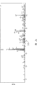
图1是Sr5(PO4)3Cl的X-射线衍射图(根据Cu Kα X-射线源)。Figure 1 is an X-ray diffraction pattern of Sr 5 (PO 4 ) 3 Cl (according to Cu Kα X-ray source).
图2显示光发射器件一个实施例的示意性的透视图,其中膜形式的荧光体与面发光型(vertical cavity surface emiting)GaN二极管接触。Figure 2 shows a schematic perspective view of one embodiment of a light emitting device in which a phosphor in the form of a film is in contact with a vertical cavity surface emitting GaN diode.
图3为显示光发射器件一个实施例的示意性的截面图。Fig. 3 is a schematic cross-sectional view showing an embodiment of a light emitting device.
图4本发明实施例1的荧光体的X-射线衍射图(X-射线源:Cu Kα)。Fig. 4 is an X-ray diffraction pattern (X-ray source: Cu Kα) of the phosphor of Example 1 of the present invention.
图5在一个图中,显示本发明实施例1的荧光体发光光谱,每个对比实施例1和对比实施例2暴露于具有发光波长为400nm的GaN发光二极管下。FIG. 5 shows, in one graph, the emission spectrum of the phosphor of Example 1 of the present invention, each of Comparative Example 1 and Comparative Example 2 exposed to a GaN light-emitting diode having an emission wavelength of 400 nm.
图6为本发明实施例2的荧光体的X-射线衍射图(X-射线源:Cu Kα)。Fig. 6 is the X-ray diffraction diagram of the phosphor of Example 2 of the present invention (X-ray source: Cu Kα).
图7为本发明实施例3的荧光体的X-射线衍射图(X-射线源:Cu Kα)。Fig. 7 is the X-ray diffraction diagram of the phosphor of Example 3 of the present invention (X-ray source: Cu Kα).
图8为本发明实施例4的荧光体的X-射线衍射图(X-射线源:Cu Kα)。Fig. 8 is an X-ray diffraction pattern (X-ray source: Cu Kα) of the phosphor of Example 4 of the present invention.
图9为显示本发明一个实施例中面发光型照明器的示意性截面图。Fig. 9 is a schematic cross-sectional view showing a surface-emitting illuminator in one embodiment of the present invention.
图10为本发明实施例5的荧光体的X-射线衍射图(X-射线源:Cu Kα)。Fig. 10 is an X-ray diffraction pattern of the phosphor of Example 5 of the present invention (X-ray source: Cu Kα).
图11为本发明实施例6的荧光体的X-射线衍射图(X-射线源:Cu Kα)。Fig. 11 is an X-ray diffraction pattern (X-ray source: Cu Kα) of the phosphor of Example 6 of the present invention.
图12为本发明实施例7的荧光体的X-射线衍射图(X-射线源:Cu Kα)。Fig. 12 is an X-ray diffraction pattern (X-ray source: Cu Kα) of the phosphor of Example 7 of the present invention.
图13为本发明实施例8的荧光体的X-射线衍射图(X-射线源:Cu Kα)。Fig. 13 is an X-ray diffraction pattern (X-ray source: Cu Kα) of the phosphor of Example 8 of the present invention.
图14为本发明实施例9的荧光体的X-射线衍射图(X-射线源:Cu Kα)。Fig. 14 is an X-ray diffraction pattern (X-ray source: Cu Kα) of the phosphor of Example 9 of the present invention.
图15为本发明实施例10的荧光体的X-射线衍射图(X-射线源:Cu Kα)。Fig. 15 is an X-ray diffraction pattern (X-ray source: Cu Kα) of the phosphor of Example 10 of the present invention.
图16为反射镜安装于分光光度计后测量的光谱Iref(λ)。Fig. 16 is the spectrum I ref (λ) measured after the reflector is installed in the spectrophotometer.
图17为当要测量量子吸收效率αq和内部量子效率ηi的样品安装于分光光度计后测量的光谱I(λ)。Fig. 17 is the spectrum I(λ) measured after the sample to be measured quantum absorption efficiency α q and internal quantum efficiency η i is installed in a spectrophotometer.
图18显示当各自在254nm和400nm激发时,Sr(5-x)Eux(PO4)3Cl的x和发光强度之间的关系。FIG. 18 shows the relationship between x and luminescence intensity of Sr (5-x) Eux (PO 4 ) 3 Cl when excited at 254 nm and 400 nm, respectively.
图19显示当各自在254nm和400nm激发时,Ca(5-x)Eux(PO4)3Cl的x和发光强度之间的关系。Fig. 19 shows the relationship between x and luminescence intensity of Ca (5-x) Eux ( PO4 ) 3Cl when excited at 254nm and 400nm respectively.
图20为BaMgAl10O17的X-射线衍射图(根据Cu Kα X-射线源)。Figure 20 is an X-ray diffraction pattern of BaMgAl 10 O 17 (according to Cu Kα X-ray source).
图21为本发明实施例20获得的荧光体的X-射线衍射图(X-射线源:CuKα)。Fig. 21 is an X-ray diffraction pattern of the phosphor obtained in Example 20 of the present invention (X-ray source: CuKα).
图22显示当各自在254nm和400nm激发时,Ba(1-x)EuxMgAl10O17的x与发光强度之间的关系。Fig. 22 shows the relationship between x and luminescence intensity of Ba (1-x) Eu x MgAl 10 O 17 when excited at 254 nm and 400 nm, respectively.
图23显示当各自在254nm和400nm激发时,Ba(1-x)EuxMgAl10O17的Eu-Eu平均距离与发光强度之间关系。Figure 23 shows the Eu-Eu average distance versus luminescence intensity for Ba (1-x) EuxMgAl10O17 when excited at 254nm and 400nm, respectively.
图24为Ba3MgSi2O8的X-射线衍射图(根据Cu Kα X-射线源)。Figure 24 is an X-ray diffraction pattern of Ba3MgSi2O8 ( according to Cu Kα X-ray source).
图25为Sr3MgSi2O8的X-射线衍射图(根据Cu Kα X-射线源)。Figure 25 is an X-ray diffraction pattern of Sr 3 MgSi 2 O 8 (according to Cu Kα X-ray source).
图26显示Ca3MgSi2O8的X-射线衍射图(根据Cu Kα X-射线源)。Figure 26 shows the X-ray diffraction pattern of Ca3MgSi2O8 (according to Cu Kα X-ray source) .
图27为实施例25获得的荧光体的X-射线衍射图(X-射线源:Cu Kα)。Fig. 27 is the X-ray diffraction pattern (X-ray source: Cu Kα) of the phosphor obtained in Example 25.
图28显示当发光波长为400nm的GaN发光二极管与本发明实施例2的荧光体或对比实施例4的荧光体结合使用时的发光光谱。FIG. 28 shows the emission spectrum when a GaN light-emitting diode with an emission wavelength of 400 nm is used in combination with the phosphor of Example 2 of the present invention or the phosphor of Comparative Example 4. FIG.
图29为实施例26获得的荧光体的X-射线衍射图(X-射线源:Cu Kα)。Figure 29 is an X-ray diffraction pattern (X-ray source: Cu Kα) of the phosphor obtained in Example 26.
图30显示当分别在254nm和400nm激发时,Ba(1-x)EuxMgSi2O8的x与发光强度之间的关系。Fig. 30 shows the relationship between x and luminescence intensity of Ba (1-x) Eu x MgSi 2 O 8 when excited at 254 nm and 400 nm, respectively.
图31为Ca3Mg3(PO4)4的X-射线衍射图(根据Cu Kα X-射线源)。Figure 31 is an X-ray diffraction pattern of Ca 3 Mg 3 (PO 4 ) 4 (according to Cu Kα X-ray source).
图32为实施例37获得的荧光体的X-射线衍射图(X-射线源:Cu Kα)。Fig. 32 is the X-ray diffraction pattern (X-ray source: Cu Kα) of the phosphor obtained in Example 37.
图33在一个图中显示,实施例37的荧光体和对比实施例6的发光光谱,分别暴露于发光波长为400nm GaN发光二极管下。FIG. 33 shows in one graph the emission spectra of the phosphor of Example 37 and Comparative Example 6, respectively exposed to a GaN light-emitting diode with an emission wavelength of 400 nm.
图34为实施例38中获得的荧光体的X-射线衍射图(X-射线源:Cu Kα);Figure 34 is the X-ray diffraction pattern (X-ray source: Cu K α) of the phosphor obtained in Example 38;
图35显示了实施例40中获得的荧光体的X-射线衍射图(X-射线源:CuKα)。Fig. 35 shows the X-ray diffraction pattern of the phosphor obtained in Example 40 (X-ray source: CuKα).
图36显示当各自在254nm和400nm激发时,EuxCa(1.5-0.5x)Mg(1.5-0.5x)(PO4)2的x与发光强度之间的关系。Fig. 36 shows the relationship between x and luminescence intensity of Eu x Ca (1.5-0.5x) Mg (1.5-0.5x) (PO 4 ) 2 when excited at 254 nm and 400 nm, respectively.
在这些图中,数字1指的是第二荧光体,2为面发光型GaN系LED,3为基底,4为光发射器件,5为安装引线(mount lead),6为内引线,7为第一光发射体(350-415nm的光发射体),8为树脂部分,其具有合并入其中的本发明的荧光体,9为导体配线,和10为模制组件(molding member)。In these figures, numeral 1 refers to a second phosphor, 2 to a surface-emitting GaN-based LED, 3 to a substrate, 4 to a light-emitting device, 5 to a mount lead, 6 to an inner lead, and 7 to a A first light emitter (light emitter of 350-415nm), 8 is a resin part having the phosphor of the present invention incorporated therein, 9 is a conductor wiring, and 10 is a molding member.
本发明最佳实施方式BEST MODE FOR CARRYING OUT THE INVENTION
本发明提供光发射器件,其包含发光为350-415nm的第一光发射体和含有荧光体的第二光发射体,其中第二光发射体中含有的该荧光体满足以下(i)到(iv)的任一条件:The present invention provides a light-emitting device comprising a first light emitter that emits light at 350-415 nm and a second light emitter containing a phosphor, wherein the phosphor contained in the second light emitter satisfies the following (i) to ( Any condition of iv):
(i)该荧光体包含:(i) the phosphor contains:
(a)结晶相,其在350-415nm的任一激发波长提供最大发光强度的Eu浓度大于在激发波长254nm提供最大发光强度的Eu浓度;和(a) a crystalline phase whose Eu concentration provides maximum luminous intensity at any excitation wavelength of 350-415 nm is greater than the Eu concentration which provides maximum luminous intensity at an excitation wavelength of 254 nm; and
(b)被Eu活化的结晶相,该Eu具有至少1.1倍在激发波长254nm下提供最大发光强度的浓度,和0.5到9倍在激发频率为400nm下提供最大发光强度的浓度;(b) a crystalline phase activated by Eu having at least 1.1 times the concentration providing maximum luminescence intensity at an excitation wavelength of 254 nm, and 0.5 to 9 times the concentration providing maximum luminescence intensity at an excitation frequency of 400 nm;
(ii)该荧光体包含结晶相,该结晶相具有的Eu-Eu平均距离,由结晶基体(crystal matrix)中Eu浓度计算,为4
(iii)该荧光体具有的量子吸收效率αq为0.8或更大;(iii) the phosphor has a quantum absorption efficiency α q of 0.8 or greater;
(iv)该荧光体具有的量子吸收效率αq与内量子效率ηi的αq·ηi乘积为0.55或更大。(iv) The phosphor has a α q·η i product of the quantum absorption efficiency α q and the internal quantum efficiency η i of 0.55 or more.
本发明中用作第二光发射体的荧光体优选具有Eu-活化的结晶相。The phosphor used as the second light emitter in the present invention preferably has a Eu-activated crystalline phase.
在上述条件(i)下,条件(a)和(b)二者必须同时满足。Under the above condition (i), both conditions (a) and (b) must be satisfied at the same time.
(a)结晶相为以下结晶相,其中在350-415nm的任何激发波长,特别地390-410nm,而且400nm提供最大发光强度的Eu浓度高于在激发波长254nm下提供最大发光强度的Eu浓度。(a) The crystalline phase is a crystalline phase in which the concentration of Eu at any excitation wavelength of 350-415 nm, particularly 390-410 nm, and 400 nm provides maximum luminous intensity is higher than the concentration of Eu that provides maximum luminous intensity at an excitation wavelength of 254 nm.
该条件必须满足因为:由于在波长254nm激发意味着被相对短波长的光激发,通过结晶基体的激发和将得到的能量传递给Eu而发生光发射,然而由于350-415nm的光被认为穿过结晶基体和直接激发Eu,Eu的浓度必须增加以获得足够的吸收效率,从而,在350-415nm的激发波长下获得高的发光强度。This condition must be satisfied because: since excitation at a wavelength of 254nm means excitation by relatively short-wavelength light, light emission occurs through excitation of the crystalline matrix and transfer of the resulting energy to Eu, whereas light at 350-415nm is considered to pass through The crystalline matrix and direct excitation of Eu, the concentration of Eu must be increased to obtain sufficient absorption efficiency and thus, high luminescence intensity at the excitation wavelength of 350-415 nm.
(b)该结晶相Eu的浓度是在254nm的激发波长下提供最大发光强度的Eu浓度的至少1.1倍,且被Eu活化,该Eu具有的浓度为0.5到9倍在400nm下提供最大发光强度的Eu浓度。(b) the crystalline phase Eu has a concentration of Eu that is at least 1.1 times greater than that of Eu that provides maximum luminous intensity at an excitation wavelength of 254 nm, and is activated by Eu that has a concentration of 0.5 to 9 times that that provides maximum luminous intensity at 400 nm. Eu concentration.
当该Eu浓度低于1.1倍在254nm激发波长下提供最大强度的Eu浓度时,因为低的吸收效率得不到足够的发光强度。考虑到发光强度等,该结晶相中Eu浓度的下限优选至少0.7倍在400nm提供最大发光强度Eu浓度,虽然上限优选6倍或更少,更加优选2.5倍或更少,特别优选2倍或更少于在400nm提供最大发光强度Eu浓度。When the Eu concentration is lower than 1.1 times the Eu concentration that provides the maximum intensity at an excitation wavelength of 254 nm, sufficient luminous intensity cannot be obtained because of low absorption efficiency. The lower limit of the Eu concentration in the crystalline phase is preferably at least 0.7 times the Eu concentration at 400 nm that provides the maximum luminous intensity in consideration of luminescence intensity, etc., while the upper limit is preferably 6 times or less, more preferably 2.5 times or less, particularly preferably 2 times or more Less Eu concentration provides maximum luminous intensity at 400nm.
提供最大发光强度的Eu浓度可以由以下比率确定:该比率为结晶基体中实际上被Eu取代的位点的数目对所有能够被Eu取代的位点的数目。该比率按照下列方式确定。The Eu concentration providing maximum luminescence intensity can be determined by the ratio of the number of sites actually substituted by Eu to the number of all sites capable of being substituted by Eu in the crystalline matrix. This ratio is determined in the following manner.
首先,假定全部位点的数目为1,测量Eu浓度在0.1-1之间按0.1变化的荧光体样品的发光强度,并且确定提供最大发光强度的Eu的比率A。然后,测量Eu浓度在A±0.09范围内按0.01变化的荧光体样品的发光强度,并且确定提供最大发光强度的比率B。当B落入0.01-0.1的范围内时,测量在Eu浓度为B±0.09范围内按0.001变化的荧光体样品的发光强度,并且确定提供最大发光强度的Eu的比率C。这些操作的最终阶段所确定的提供最大发光强度的Eu比率,被认为是本发明的提供最大发光强度的Eu比率,由该值确定提供最大发光强度的Eu浓度。更特别地,当结晶基体中可取代的Eu摩尔数为3时,提供最大发光强度的Eu浓度通过提供最大发光强度的Eu比率乘以3而获得。不大于0.1的Eu比率被分为更窄的间隔,因为当在附近存在提供最大发光强度的Eu浓度峰时,发光强度相对于Eu浓度的变化比率倾向于变大。First, assuming that the number of all sites is 1, the luminescence intensity of a phosphor sample whose Eu concentration is varied by 0.1 between 0.1-1 is measured, and the ratio A of Eu providing the maximum luminescence intensity is determined. Then, the luminescence intensity of the phosphor sample whose Eu concentration was changed by 0.01 in the range of A±0.09 was measured, and the ratio B providing the maximum luminescence intensity was determined. When B falls within the range of 0.01-0.1, the luminescence intensity of the phosphor sample varying by 0.001 within the Eu concentration range of B±0.09 is measured, and the ratio C of Eu providing the maximum luminescence intensity is determined. The Eu ratio providing the maximum luminous intensity determined at the final stage of these operations is regarded as the Eu ratio providing the maximum luminous intensity in the present invention, and the Eu concentration providing the maximum luminous intensity is determined from this value. More specifically, when the substitutable Eu mole number in the crystalline matrix is 3, the Eu concentration providing the maximum luminescence intensity is obtained by multiplying the Eu ratio providing the maximum luminescence intensity by 3. The Eu ratio of not more than 0.1 is divided into narrower intervals because the change ratio of the luminous intensity with respect to the Eu concentration tends to become larger when there is an Eu concentration peak providing the maximum luminous intensity nearby.
上述条件(ii)中,由本发明将要使用的结晶相的结晶基体中的Eu浓度所计算的Eu-Eu平均距离为4
当Eu-Eu平均距离太短时,发生称为浓度猝灭的现象,导致发光强度降低的趋势。假如Eu-Eu平均距离太长,在另一方面,也存在发光强度降低的趋势,因为荧光体对来自第一光发射体的激发光吸收效率变差。When the Eu-Eu average distance is too short, a phenomenon called concentration quenching occurs, resulting in a tendency for the luminous intensity to decrease. If the Eu-Eu average distance is too long, on the other hand, there is also a tendency for the luminous intensity to decrease because the phosphor absorbs the excitation light from the first light emitter poorly.
在上述条件(iii)下,本发明将要使用的荧光体的量子吸收效率αq为0.8或更大。考虑到发光强度,该效率优选0.9或更大,更加优选0.95或更大。可能的量子吸收效率αq的上限实质上为1。Under the above condition (iii), the phosphor to be used in the present invention has a quantum absorption efficiency α q of 0.8 or more. The efficiency is preferably 0.9 or more, more preferably 0.95 or more in consideration of luminous intensity. The upper limit of the possible quantum absorption efficiency α q is substantially unity.
当荧光体满足上述条件(iii)时,从第一光发射体释放的、能够导致荧光体的初级激发的光子数目增加,导致单位时间内由荧光体释放的光子数目增加。简而言之,可以获得具有高发光强度的光发射器件。此处所用的术语“初级激发”是指,由于Eu自旋状态变化的能量激发(其通常称为“发光中心激发”),由于在每个离子附近具有存在几率的电子平均数目变化导致的能量激发(通常称为“CT激发”),和由于电子的键-键转移的能量激发(通常称为“键激发”)。When the phosphor satisfies the above condition (iii), the number of photons released from the first light emitter that can cause primary excitation of the phosphor increases, resulting in an increase in the number of photons released by the phosphor per unit time. In short, a light-emitting device with high luminous intensity can be obtained. The term "primary excitation" as used herein refers to energy excitation due to Eu spin state change (which is often referred to as "luminescence center excitation"), the energy due to the change in the average number of electrons that have a probability of being in the vicinity of each ion excitation (often referred to as "CT excitation"), and energy excitation due to bond-to-bond transfer of electrons (often referred to as "bond excitation").
在上述条件(iv)下,本发明将要使用的荧光体的量子吸收效率αq和内量子效率ηi的乘积αq·ηi,为0.55或更大,优选0.6或更大,更加优选0.65或更大。Under the above condition (iv), the product α q ·η i of the quantum absorption efficiency α q and the internal quantum efficiency η i of the phosphor to be used in the present invention is 0.55 or greater, preferably 0.6 or greater, more preferably 0.65 or larger.
基本上,αq可能的上限为1,同时ηi可能的上限为0.99。当荧光体满足上述条件(iv)时,αq和ηi通常分别落入0.55≤αq≤1和0.55≤ηi≤0.99内。当荧光体满足上述条件(iv)时,由第一光发射体释放的光子导致的初级激发中,导致光子形成的初级激发的比例将会增加,其结果是每单位时间荧光体释放光子数目增加。简而言之,可以获得具有高的发光强度的光发射器件。Basically, the upper limit possible for α q is 1, while the upper limit possible for η i is 0.99. When the phosphor satisfies the above condition (iv), α q and η i usually fall within 0.55≤α q ≤1 and 0.55≤η i ≤0.99, respectively. When the phosphor satisfies the above condition (iv), among the primary excitations caused by the photons released by the first light emitter, the proportion of the primary excitations that lead to the formation of photons will increase, resulting in an increase in the number of photons released by the phosphor per unit time . In short, a light-emitting device with high luminous intensity can be obtained.
期望量子吸收效率αq自身的增大以提高亮度,因为它通常导致被引入样品的来自激发光源的光子数目增加。然而,在实际中,试着通过升高作为发光中心的Eu等的浓度增大αq并没有导致足够的发光强度,因为在光子到达最终的光致激发步骤之前,样品晶体中能量变为光子激发的几率增大。An increase in the quantum absorption efficiency αq itself is expected to increase brightness, since it generally leads to an increase in the number of photons introduced into the sample from the excitation light source. However, in practice, trying to increase αq by increasing the concentration of Eu, etc. as the luminescence center did not result in sufficient luminescence intensity, because before the photons reach the final photoexcitation step, the energy in the sample crystal becomes photon Increased chance of triggering.
然而,已经发现,具体地,当350-415nm被选作为激发光源的波长,和具有高的量子吸收效率αq的荧光体被用作光发射器件的第二光发射体时,上述非光致激发步骤被抑制,具有高的发光强度的光发射器件可以被实现。However, it has been found that, in particular, when 350-415 nm is selected as the wavelength of the excitation light source, and a phosphor having a high quantum absorption efficiency α q is used as the second light emitter of the light-emitting device, the above-mentioned non-photoinduced The excitation step is suppressed, and a light-emitting device with high luminous intensity can be realized.
还发现含有αq和αq·ηi都高的荧光体的第二光发射体与具有波长为350-415nm的第一光发射体的结合使用,使得提供具有更加优选性能的光发射器件成为可能。It has also been found that the combination of a second light emitter containing a phosphor having high α q and α q η i with a first light emitter having a wavelength of 350-415 nm makes it possible to provide a light emitting device with more preferable properties possible.
接下来将描述用于确定量子吸收效率αq和内量子效率ηi的方法。Next, a method for determining the quantum absorption efficiency α q and the internal quantum efficiency η i will be described.
将要测量的粉末状等的荧光体样品填充入单元中,同时平面化样品表面以保持测量具有足够的精度,该单元安装在装备有积分球等的分光光度计上。此处可以使用的分光光度计为,例如,“MCPD2000”,Otsuka Electronics产品。此处使用的积分球的目的是计算所有被样品反射的光子和那些由样品经光致发光释放的光子,换言之,目的是防止光子散射出测量体系和偏离测量数据。接着,分光光度计安装用于激发荧光体的光源。A phosphor sample in powder form or the like to be measured is filled into a cell while planarizing the sample surface to keep measurement with sufficient accuracy, and the cell is mounted on a spectrophotometer equipped with an integrating sphere or the like. A spectrophotometer usable here is, for example, "MCPD2000", a product of Otsuka Electronics. The purpose of the integrating sphere used here is to count all photons reflected by the sample and those released by the sample via photoluminescence, in other words, the purpose is to prevent photons from scattering out of the measurement system and deviating from the measurement data. Next, the spectrophotometer is equipped with a light source for exciting the phosphor.
作为光源,例如,可以应用Xe灯,它的发射峰波长通过使用滤镜等调节成400nm。要测量的样品暴露于来自光源的峰波长调节成400nm的光,测量样品的发光光谱。这样测量的光谱还包括,由样品用来自激发光源的光(其在下文中将简称为“激发光”)经光致激发而释放的光子,起源于经样品对激发光反射的光子。吸收效率αq为样品吸收的激发光的光子数目Nabs除以激发光的总光子数目N而得到的商。后者总的激发光光子数目N按以下方式确定。首先,对激发光基本上具有100%反射率R的物质,例如,反射镜,如“Spectralon”(Labsphere产品,对400nm激发光具有98%的反射率)被作为待测量的物体安装于分光光度计上,测量其反射光谱Iref(λ)。根据(式1)由反射光谱Iref(λ)测定的数字与N成比例。As a light source, for example, an Xe lamp whose emission peak wavelength is adjusted to 400 nm by using a filter or the like can be used. The sample to be measured is exposed to light from a light source whose peak wavelength is adjusted to 400 nm, and the light emission spectrum of the sample is measured. The spectrum thus measured also includes photons released by photoexcitation of the sample with light from an excitation light source (which will hereinafter be simply referred to as "excitation light") originating from photons reflected by the sample against the excitation light. The absorption efficiency α q is the quotient obtained by dividing the photon number N abs of the excitation light absorbed by the sample by the total photon number N of the excitation light. The latter total photon number N of excitation light is determined in the following manner. First, a substance having substantially 100% reflectance R to excitation light, for example, a mirror, such as "Spectralon" (Labsphere product, having 98% reflectance to 400nm excitation light) is installed on the spectrophotometer as an object to be measured. On the meter, measure its reflection spectrum I ref (λ). The number determined from the reflection spectrum I ref (λ) according to (Equation 1) is proportional to N.
上述式中,积分区间可以是Iref(λ)基本上具有有效值的区间。Iref(λ)的一个实施例显示于图16中,该情况下,380nm-420nm足够用作区间。前者Nabs与根据(式2)确定的量成比例。In the above formula, the integration interval may be an interval in which I ref (λ) basically has a valid value. An example of I ref (λ) is shown in Figure 16, in which case 380nm-420nm is sufficient as an interval. The former Na abs is proportional to the quantity determined according to (Equation 2).
在上述式中,I(λ)为当安装样品测量其αq时的反射光谱。(式2)的积分范围与对(式1)的定义相同。通过如此确定的积分范围,(式2)的第二项对应于样品对激发光反射产生的光子数目,即,从样品产生的总光子数目,减去激发光经由光致发光产生的光子所得到的光子数目。在实际中,光谱作为数字的数据获得,其被一些相应于λ的有限带宽相除,使得(式1)和(式2)的积分通过基于带宽的有限和确定。这导致下列等式:In the above formula, I(λ) is the reflectance spectrum when the sample is mounted and its α q is measured. The integral range of (Formula 2) is the same as the definition of (Formula 1). With the integration range thus determined, the second term of (Equation 2) corresponds to the number of photons generated by the sample on reflection of the excitation light, that is, obtained by subtracting the photons generated by the excitation light via photoluminescence from the total number of photons generated by the sample number of photons. In practice, the spectrum is obtained as digital data that is divided by some finite bandwidth corresponding to λ such that the integrals of (Equation 1) and (Equation 2) are determined by a bandwidth-based finite sum. This leads to the following equation:
αq=Nabs/N=(式2)/(式1)α q =N abs /N=(Formula 2)/(Formula 1)
确定内量子效率ηi的方法将在以下描述。内量子效率ηi是通过把光致激发产生的光子数目NPL除以样品吸收的光子数目Nabs获得的商。A method of determining the internal quantum efficiency η i will be described below. The internal quantum efficiency η i is the quotient obtained by dividing the number of photons N PL produced by photoexcitation by the number of photons absorbed by the sample Na abs .
NPL与(式3)确定的量成比例:N PL is proportional to the quantity determined by (Equation 3):
∫λ·I(λ)dλ (式3)∫λ·I(λ)dλ (Formula 3)
该式中,积分区间被限定于由样品光致发光所产生的光子的波长区域,由此样品反射贡献的光子从I(λ)中被除去。更特别地,对于(式3)积分的下限,(式1)积分的上端被略去,适合于包括产自光致激发的光谱的区域被用作上端。图17为I(λ)的实例。该情形下,(式3)的积分区域可以是420nm-520nm。该方式中,ηi可以由下列等式ηi=(式3)/(式2)确定。In this equation, the integration interval is limited to the wavelength region of photons generated by sample photoluminescence, whereby photons contributed by sample reflection are removed from I(λ). More specifically, for the lower limit of the integration of (Equation 3), the upper end of the integration of (Equation 1) is omitted, and the region suitable for including the spectrum resulting from photoexcitation is used as the upper end. Fig. 17 is an example of I(λ). In this case, the integration region of (Formula 3) may be 420nm-520nm. In this manner, η i can be determined by the following equation η i =(Formula 3)/(Formula 2).
可以进行类似于应用在确定αq的方式,获得作为数字数据的光谱积分。Spectral integrals obtained as digital data can be performed in a manner similar to that applied in the determination of αq .
本发明中,二价Eu或三价Eu都可以用作Eu活化剂,但它们在光发射传递过程中不同。二价Eu趋向于被具有较长波长的紫外光激发使得优选二价Eu。在本发明中,术语“Eu浓度”意思为由二价Eu数目确定的Eu浓度。In the present invention, either divalent Eu or trivalent Eu can be used as the Eu activator, but they are different in the light emission transfer process. Divalent Eu tends to be excited by ultraviolet light having a longer wavelength so that divalent Eu is preferred. In the present invention, the term "Eu concentration" means the Eu concentration determined by the number of divalent Eu.
当荧光体同时含有二价Eu和三价Eu时,Eu浓度由二价Eu数目确定。When the phosphor contains both divalent Eu and trivalent Eu, the Eu concentration is determined by the number of divalent Eu.
在本发明光发射器件中,第二光发射体需要含有能够满足上述条件(i)到(iv)的任何一个的荧光体。然而,具体地优选合并入能够满足条件1和3的荧光体,因为它能够制作具有较高发光强度的光发射器件。In the light-emitting device of the present invention, the second light-emitting body needs to contain a phosphor capable of satisfying any one of the above-mentioned conditions (i) to (iv). However, incorporation of a phosphor capable of satisfying
虽然对于构成满足任一上述条件的荧光体的材料没有特定的限制,优选具有结晶相的材料。更加优选选自那些具有下述式[1]-[4]的化学组合物结晶相(其可以简称为“式[1]-[4]的结晶相”)的材料。理想的荧光体倾向于通过从那些式[1]-[4]的优选结晶相中选择而得到。荧光体可以在不损害其性能的范围内包含光散射物质等,作为除结晶相之外的组分。Although there is no specific limitation on the material constituting the phosphor satisfying any of the above conditions, a material having a crystalline phase is preferable. More preferably, materials selected from those having a crystalline phase of a chemical composition of the following formulas [1] to [4] (which may be simply referred to as "a crystalline phase of formulas [1] to [4]"). Ideal phosphors tend to be obtained by selecting from among those preferred crystal phases of formulas [1] to [4]. The phosphor may contain a light-scattering substance or the like as a component other than the crystal phase within a range that does not impair its performance.
荧光体通常含有结晶相的量为10重量%或更大,优选50重量%或更大,更加优选80重量%或更大。Phosphors usually contain a crystalline phase in an amount of 10% by weight or more, preferably 50% by weight or more, more preferably 80% by weight or more.
在光发射器件中,其具有发光为350-415nm的第一光发射体和通过暴露于来自第一光发射体的光发射可见光的第二光发射体,本发明的光发射器件,其具备含有任何一个式[1]-[4]结晶相的荧光体的第二光发射体,是新颖的并且具有优于通常光发射器件的发光强度。In a light-emitting device, which has a first light emitter that emits light at 350-415 nm and a second light emitter that emits visible light by being exposed to light from the first light emitter, the light-emitting device of the present invention is equipped with The second light emitter of any one of the phosphors in the crystalline phase of formulas [1]-[4] is novel and has a luminous intensity superior to that of conventional light emitting devices.
下面将描述以式[1]-[4]为代表的结晶相:Crystal phases represented by formulas [1]-[4] will be described below:
<模式1><
EuaSrbM1 5-a-b(PO4)cXd [1]Eu a Sr b M 1 5-ab (PO 4 ) c X d [1]
每个M1表示除Eu和Sr之外的金属元素。考虑到发光强度等,优选调节M1中Ba,Mg,Ca,Zn和Mn的总量至70mol%或更多。更加优选调节M1中Ba,Mg和Ca的总量至70mol%或更多。还更加优选调节M1中Ba,Mg和Ca的总量至90mol%或更多。还更加优选M1全部由至少一个选自Ba,Mg,Ca,Zn和Mn的元素组成,和最优选M1全部由至少一个选自Ba,Mg,和Ca的元素组成。Each M 1 represents a metal element other than Eu and Sr. In consideration of luminous intensity and the like, it is preferable to adjust the total amount of Ba, Mg, Ca, Zn and Mn in M1 to 70 mol% or more. It is more preferable to adjust the total amount of Ba, Mg and Ca in M1 to 70 mol% or more. It is still more preferable to adjust the total amount of Ba, Mg and Ca in M1 to 90 mol% or more. Still more preferably M1 consists entirely of at least one element selected from Ba, Mg, Ca, Zn, and Mn, and most preferably M1 consists entirely of at least one element selected from Ba, Mg, and Ca.
当上述之外的金属元素被引入作为M1时,理想的加入具有与Sr或这5种金属元素(Ba,Mg,Ca,Zn和Mn)等价数目的金属元素,即,有助于保持晶体结构的二价金属元素。少量的一价,三价,四价,五价或六价金属元素可以为了加速复合氧化物结晶的目的引入,结晶由烧结时固体中二价金属元素和发光中心Eu2+的扩散导致。在一个实施例中,Sr5(PO4)3Cl:Eu荧光体中部分Sr2+可以被等摩尔量的Li+和Ga3+取代,同时保持电荷补偿效应。也可能用作为敏化剂的金属元素取代。When a metal element other than the above is introduced as M1 , it is desirable to add a metal element having an equivalent number to Sr or these 5 metal elements (Ba, Mg, Ca, Zn, and Mn), that is, to help maintain Crystal structure of divalent metal elements. A small amount of monovalent, trivalent, tetravalent, pentavalent or hexavalent metal elements can be introduced for the purpose of accelerating the crystallization of composite oxides, which is caused by the diffusion of divalent metal elements and luminescent centers Eu 2+ in the solid during sintering. In one embodiment, part of Sr 2+ in the Sr 5 (PO 4 ) 3 Cl:Eu phosphor can be replaced by Li + and Ga 3+ in equimolar amounts, while maintaining the charge compensation effect. It is also possible to substitute metal elements as sensitizers.
X表示除PO4之外的一价阴离子基团。该阴离子基团的实例包括卤素离子和氢氧根离子(OH-)。卤素离子包括Cl-,F-和Br-,其中优选Cl-。考虑到发光强度等,优选50mol%或更多,更加优选70mol%或更多,特别地优选90mol%或更多的X由卤素离子构成。X represents a monovalent anionic group other than PO4 . Examples of the anionic group include halide ions and hydroxide ions (OH − ). Halogen ions include Cl - , F - and Br - , among which Cl - is preferred. In consideration of luminescence intensity and the like, preferably 50 mol% or more, more preferably 70 mol% or more, particularly preferably 90 mol% or more of X is composed of halide ions.
当50mol%或更多的X由卤素离子构成时,剩余的阴离子基团可能含有氢氧基离子等。在最优选的模式中,50mol%或更多,特别地70mol%或更多,还更加优选90mol%或更多的X由Cl-构成。该情形下,其他的卤素离子和氢氧根离子可以用作剩余的基团。When 50 mol% or more of X is composed of halide ions, the remaining anion groups may contain hydroxide ions or the like. In the most preferred mode, 50 mol% or more, especially 70 mol% or more, still more preferably 90 mol% or more of X is composed of Cl- . In this case, other halide ions and hydroxide ions can be used as the remaining groups.
式[1]中,Eu的摩尔比率是大于0和满足a+b≤5的数字。当a+b=5时,式[1]的结晶相不含有M1。更特别地,通常满足0<a<5,通常a≥0.0001,优选a≥0.001,更加优选a≥0.005。考虑到发光强度等,通常满足a≥0.1,优选a≥0.2,更加优选a>0.2,还更加优选a≥0.3,特别地优选a≥0.4,还更加优选a≥0.45。In formula [1], the molar ratio of Eu is a number greater than 0 and satisfying a+b≦5. When a+b=5, the crystal phase of formula [1] does not contain M 1 . More specifically, 0<a<5 is usually satisfied, usually a≥0.0001, preferably a≥0.001, more preferably a≥0.005. In consideration of luminous intensity and the like, a≥0.1 is usually satisfied, preferably a≥0.2, more preferably a>0.2, still more preferably a≥0.3, particularly preferably a≥0.4, still more preferably a≥0.45.
当作为发射中心离子的Eu2+摩尔比率太小时,发光强度趋向于变低。当其太大时,在另一方面,发光强度由于称为浓度猝灭的现象也趋向于降低。因此,通常满足a≤4.8,优选a≤3,更加优选a≤2.5,特别地优选a≤2,最优选a≤1.5。When the molar ratio of Eu 2+ as an emission center ion is too small, the luminous intensity tends to become low. When it is too large, on the other hand, the luminous intensity also tends to decrease due to a phenomenon called concentration quenching. Therefore, a≤4.8 is usually satisfied, preferably a≤3, more preferably a≤2.5, especially preferably a≤2, most preferably a≤1.5.
此外,使用满足a>0.2,而且a≥0.3特别地优选,以便获得光发射器件,其由具有满足上述条件3和/或4的荧光体的第二光发射体构成。Furthermore, the use satisfying a>0.2, but also a≥0.3 is particularly preferred in order to obtain a light-emitting device consisting of a second light-emitting body having a phosphor
式[1]中,Sr的摩尔比率b为0或更大,优选大于0和满足a+b≤5。更特别地,b满足0≤b<5,优选0<b<5。通常b调节成落入下列范围:b≥0.01,优选b≥0.1,更加优选b≥0.2。考虑到发光强度等,最优选调节b落入下列范围:b≥3,特别地b≥4。在主要由(Sr,Ba,Ca)5(PO4)3Cl:Eu2+构成的结晶相中,Sr的摩尔比率没有被窄限定。在本发明中,采用具有b<5作为上限的相对大的数字使得获得显著高的发光强度成为可能。当Sr的摩尔比率更小时,换言之,b代表较小的数字,特别地0,原料成本可以减小。因而优选较小的Sr摩尔比率。具体而言,优选调节Ca的摩尔比率至50mol%或更多同时减小(b)。该情形下,相对高的发光强度也可以获得。In formula [1], the molar ratio b of Sr is 0 or more, preferably more than 0 and satisfies a+b≦5. More particularly, b satisfies 0≦b<5, preferably 0<b<5. Usually b is adjusted to fall within the following range: b≥0.01, preferably b≥0.1, more preferably b≥0.2. In consideration of luminous intensity and the like, it is most preferable to adjust b to fall within the following range: b≧3, particularly b≧4. In the crystalline phase mainly composed of (Sr, Ba, Ca) 5 (PO 4 ) 3 Cl:Eu 2+ , the molar ratio of Sr is not narrowly defined. In the present invention, the use of relatively large numbers with b<5 as an upper limit makes it possible to obtain remarkably high luminous intensities. When the molar ratio of Sr is smaller, in other words, b represents a smaller number, especially 0, the raw material cost can be reduced. A smaller Sr molar ratio is thus preferred. Specifically, it is preferable to adjust the molar ratio of Ca to 50 mol% or more while reducing (b). In this case, relatively high luminous intensity can also be obtained.
式[1]中,除了上述a和b的条件外,足够的发光强度可以通过满足a≥0.1和b≥3中之一达到。因此,不是经常必要同时都满足这些条件,如果a和b之一满足上述等式。In formula [1], in addition to the above-mentioned conditions of a and b, sufficient luminous intensity can be achieved by satisfying one of a≥0.1 and b≥3. Therefore, it is not always necessary to satisfy both of these conditions if one of a and b satisfies the above equation.
优选a和b结合的实例包括:(1)a≥0.1和b≥0.01,(2)a≥0.1和b≥0.1,(3)a≥0.1和b≥0.2,(4)a≥0.2和b>0.01,(5)a≥0.2和b≥0.1,(6)0.0001≤a和b≥3,(7)0.001≤a和b≥3,(8)0.005≤a和b≥3,(9)0.0001≤a和b≥4,(10)0.001≤a和b≥4,和(11)0.005≤a和b≥4。Examples of preferred combinations of a and b include: (1) a≥0.1 and b≥0.01, (2) a≥0.1 and b≥0.1, (3) a≥0.1 and b≥0.2, (4) a≥0.2 and b >0.01, (5) a≥0.2 and b≥0.1, (6) 0.0001≤a and b≥3, (7) 0.001≤a and b≥3, (8) 0.005≤a and b≥3, (9) 0.0001≤a and b≥4, (10) 0.001≤a and b≥4, and (11) 0.005≤a and b≥4.
本发明中,特别地优选满足a≥0.1和b≥3二者,其目的是获得较高的发光强度。由此观点,a和b结合的实例优选包括:(1)a≥0.1和b≥3,(2)a≥0.1和b≥4,(3)a≥0.2和b≥3,(4)a≥0.2和b≥4。发光强度可以通过满足a>0.2和b≥3二者增大。In the present invention, it is particularly preferable to satisfy both a≧0.1 and b≧3 for the purpose of obtaining higher luminous intensity. From this point of view, examples of the combination of a and b preferably include: (1) a≥0.1 and b≥3, (2) a≥0.1 and b≥4, (3) a≥0.2 and b≥3, (4) a ≥0.2 and b≥4. The luminous intensity can be increased by satisfying both a>0.2 and b≥3.
由此观点,a和b结合的实例优选包括:(1)a>0.2和b≥3,(2)a>0.2和b≥4,(3)a≥0.3和b≥3,(4)a≥0.3和b≥4,(5)a≥0.4和b≥3,(6)a≥0.4和b≥4,(7)a≥0.45和b≥3,和(8)a≥0.45和b≥4。From this point of view, examples of the combination of a and b preferably include: (1) a>0.2 and b≥3, (2) a>0.2 and b≥4, (3) a≥0.3 and b≥3, (4) a ≥0.3 and b≥4, (5) a≥0.4 and b≥3, (6) a≥0.4 and b≥4, (7) a≥0.45 and b≥3, and (8) a≥0.45 and b≥ 4.
c为满足以下的数字:c≥2.7,优选c≥2.8,更加优选c≥2.9和c≤3.3,优选c≤3.2,更加优选c≤3.1。当这些上限和下限结合时,c优选为2.7≤c≤3.3,更加优选2.8≤c≤3.2,更加优选2.9≤c≤3.1。c is a number satisfying the following: c≥2.7, preferably c≥2.8, more preferably c≥2.9 and c≤3.3, preferably c≤3.2, more preferably c≤3.1. When these upper and lower limits are combined, c is preferably 2.7≤c≤3.3, more preferably 2.8≤c≤3.2, still more preferably 2.9≤c≤3.1.
d代表满足以下的数字:d≥0.9,优选d≥0.93,更加优选d≥0.95和d≤1.1,优选d≤1.07,更加优选d≤1.05。当这些上限和下限结合时,d为0.9≤d≤1.1,优选0.93≤d≤1.07,更加优选0.95≤d≤1.05。d represents a number satisfying the following: d≥0.9, preferably d≥0.93, more preferably d≥0.95 and d≤1.1, preferably d≤1.07, more preferably d≤1.05. When these upper and lower limits are combined, d is 0.9≤d≤1.1, preferably 0.93≤d≤1.07, more preferably 0.95≤d≤1.05.
在式[1]的基本晶体EuaSrbM1 5-a-b(PO4)cXd中,一些晶体缺陷的产生对本发明所要的荧光性能具有小的影响,使得其可以在不同于a,b,c和d的上述范围内使用。In the basic crystal Eu a Sr b M 1 5-ab (PO 4 ) c X d of formula [1], the generation of some crystal defects has a small impact on the desired fluorescence properties of the present invention, so that it can be different from a, b, c and d are used within the above ranges.
一般地,A5(PO4)3Cl(A表示碱土金属)具有六方晶体结构及其空间群为P63/m。Generally, A 5 (PO 4 ) 3 Cl (A represents an alkaline earth metal) has a hexagonal crystal structure and its space group is P6 3 /m.
式[1]的结晶相具有上述的A5(PO4)3Cl晶体结构。Sr5(PO4)3Cl典型的X-射线衍射图(由粉末X-射线衍射数据基)在图1中示出。Sr5(PO4)3Cl的Sr位点可以在宽的组合物范围内,用二价金属如Ba,Mg,Ca,Zn或Mn取代。如果其量小,也可以用具有不同价的金属如Na或La取代。它的Cl位点可以用不改变结构的阴离子种如F,Br或OH取代。本发明中的结晶相对应于以下结晶相:其具有用Sr作为阳离子种的取代产物的基体(matrix),和阳离子位点被作为活化剂的Eu2+取代。The crystal phase of the formula [1] has the above-mentioned A 5 (PO 4 ) 3 Cl crystal structure. A typical X-ray diffraction pattern (from powder X-ray diffraction data base) of Sr 5 (PO 4 ) 3 Cl is shown in FIG. 1 . The Sr sites of Sr 5 (PO 4 ) 3 Cl can be substituted with divalent metals such as Ba, Mg, Ca, Zn or Mn within a wide composition range. If its amount is small, it can also be substituted with a metal having a different valence such as Na or La. Its Cl sites can be substituted with anionic species such as F, Br or OH that do not change the structure. The crystals in the present invention correspond to a crystal phase having a matrix of substitution products with Sr as a cationic species, and cationic sites are substituted with Eu 2+ as an activator.
含有式[1]结晶相的荧光体被来自第一光发射体的350-415nm光激发,并且产生具有很高发光强度的可见光。The phosphor containing the crystalline phase of formula [1] is excited by 350-415 nm light from the first light emitter, and generates visible light with very high luminous intensity.
具体而言,该含有满足上述条件(iii)和/或(iv)的荧光体的第二光发射体,趋向于通过从式[1]的荧光体中选择优选的荧光体(其被合并入第二光发射体中)得到。Specifically, the second light emitter containing phosphors satisfying the above conditions (iii) and/or (iv) tends to be obtained by selecting a preferred phosphor from the phosphors of formula [1] (which is incorporated into in the second light emitter).
<模式2><
M2 (e-ex)M2’ exEufM3 (g-gy)M3’ gyM4 (h-hz)M4’ hzOi [2]M 2 (e-ex) M 2' ex Eu f M 3 (g-gy) M 3' gy M 4 (h-hz) M 4' hz O i [2]
M2表示至少一个选自Ba,Sr和Ca的元素。 M2 represents at least one element selected from Ba, Sr and Ca.
在位点M2取代的阳离子M2’是一价金属元素或具有相对大的离子半径的二价金属元素。它表示一价金属元素或二价金属元素(除Ba,Sr,Ca和Eu),当络合数为6时在其二价形式具有半径为0.92
考虑到发光强度等,在M2和M2’之和中的Ba,Sr和Ca总量的比率优选调节至80mol%或更多。更加优选在M2和M2’之和中的Ba的比率为30mol%或更多,同时,M2和M2’之和中的Sr或Ca的比率为20mol%或更多。The ratio of the total amount of Ba, Sr and Ca in the sum of M2 and M2 ' is preferably adjusted to 80 mol% or more in consideration of luminous intensity and the like. More preferably, the ratio of Ba in the sum of M2 and M2 ' is 30 mol% or more, while the ratio of Sr or Ca in the sum of M2 and M2' is 20 mol% or more.
M3表示至少一个选自Mg和Zn的元素。M 3 represents at least one element selected from Mg and Zn.
在位点M3取代的阳离子M3’是相对小的二价阳离子。它表示当络合数为6时在二价形式具有的半径小于0.92
考虑到发光强度等,在M3和M3’之和中的Mg和Zn总量的比率优选调节成80mol%或更多。The ratio of the total amount of Mg and Zn in the sum of M 3 and M 3' is preferably adjusted to 80 mol% or more in consideration of luminous intensity and the like.
M4表示至少一个选自Al,Ga和Sc的元素,优选Al。M 4 represents at least one element selected from Al, Ga and Sc, preferably Al.
M4’表示三价金属元素(除Al,Ga和Sc),它的特定实例包括Y,In和Lu。M 4 ′ represents a trivalent metal element (except Al, Ga, and Sc), and specific examples thereof include Y, In, and Lu.
考虑到发光强度等,元素M4和M4’之和中的Al比率优选调节成80mol%或更多。The ratio of Al in the sum of elements M 4 and M 4' is preferably adjusted to 80 mol% or more in consideration of luminous intensity and the like.
为了加速复合氧化物结晶的目的,该结晶由烧结时固体中二价或三价金属元素和发光中心Eu2+的扩散导致,可以在不损害本发明优点的范围内引入少量的一价,三价,四价,五价或六价金属元素作为M2’和M3’,以及一价,二价,四价,五价或六价金属元素作为M4’。For the purpose of accelerating the crystallization of composite oxides, which are caused by the diffusion of divalent or trivalent metal elements and luminescent centers Eu 2+ in the solid during sintering, a small amount of monovalent, trivalent valent, tetravalent, pentavalent or hexavalent metal elements as M 2' and M 3' , and monovalent, divalent, tetravalent, pentavalent or hexavalent metal elements as M 4' .
在一个实施例中,在BaMgAl10O17:Eu荧光体中部分Ba2+可以用等摩尔量的Li+和Ga3+取代同时保持电荷补偿效应。为了控制发光波长或发光强度,它可以用金属元素如Mn取代其将用作敏化剂。In one embodiment, part of Ba 2+ in the BaMgAl 10 O 17 :Eu phosphor can be replaced with equimolar amounts of Li + and Ga 3+ while maintaining the charge compensation effect. In order to control the emission wavelength or emission intensity, it can be replaced with metal elements such as Mn which will be used as a sensitizer.
式[2]中Eu的摩尔比率f为满足f≥0.11,优选f≥0.15和f≤0.99,优选f≤0.65的数字。当发射中心离子Eu2+的摩尔比率f太小时,发光强度趋向于变小。当f太大时,在另一方面,由于称为浓度猝灭的现象,发光强度也趋向于降低。The molar ratio f of Eu in formula [2] is a number satisfying f≥0.11, preferably f≥0.15 and f≤0.99, preferably f≤0.65. When the molar ratio f of the emission center ion Eu 2+ is too small, the luminescence intensity tends to become small. When f is too large, on the other hand, the luminous intensity also tends to decrease due to a phenomenon called concentration quenching.
e代表满足以下的的数字:(e+f)≥0.9,优选(e+f)≥0.95,更加优选(e+f)≥0.98和(e+f)≤1.1,优选(e+f)≤1.05,更加优选(e+f)≤1.02。e represents the number satisfying the following: (e+f)≥0.9, preferably (e+f)≥0.95, more preferably (e+f)≥0.98 and (e+f)≤1.1, preferably (e+f)≤ 1.05, more preferably (e+f)≤1.02.
g代表满足以下的数字:g≥0.9和g≤1.1。g represents a number satisfying the following: g≥0.9 and g≤1.1.
h代表满足以下的数字:h≥9和h≤11。h represents a number satisfying the following: h≥9 and h≤11.
i代表满足以下的数字:i≥15.3和i≤18.7。i represents a number satisfying the following: i≥15.3 and i≤18.7.
x代表满足以下的数字:x≥0和x<0.2,优选x≤0.1,更加优选x≤0.05,其中特别地优选x=0。x represents a number satisfying the following: x≧0 and x<0.2, preferably x≦0.1, more preferably x≦0.05, wherein x=0 is particularly preferred.
y代表满足以下的数字:y≥0和y<0.2,优选y≤0.1,更加优选y≤0.05,其中y=0特别地优选。最优选x和y各自代表0。y represents a number satisfying the following: y≧0 and y<0.2, preferably y≦0.1, more preferably y≦0.05, where y=0 is particularly preferred. Most preferably x and y each represent 0.
z代表满足以下的数字:z≥0和z<0.2,优选z≤0.1,更加优选z≤0.05,其中z=0特别地优选。z represents a number satisfying the following: z≥0 and z<0.2, preferably z≤0.1, more preferably z≤0.05, where z=0 is particularly preferred.
在上述式[2]的基本晶体M2 eEufM3 gM4 hOi中,存在一些阳离子缺乏或氧缺乏对本发明所要的荧光性能具有小的影响,使得其可以在与(e+f),g,h和i不同的上述范围内使用。In the basic crystal M 2 e Eu f M 3 g M 4 h O i of the above formula [2], there are some cation deficiencies or oxygen deficiencies that have a small impact on the desired fluorescent properties of the present invention, so that it can be compared with (e+ f), g, h and i are used within the above ranges different.
一般地,BaMgAl10O17晶体具有六方体系并且其空间群为P63/mmc。Generally, BaMgAl 10 O 17 crystal has a hexagonal system and its space group is P6 3 /mmc.
以式[2]为代表的晶体结构通常是上述BaMgAl10O17结构。图20中,BaMgAl10O17典型的X-射线衍射图(由粉末X-射线衍射数据基)。在(Ba,Sr,Ca)(Mg,Zn)Al10O17中,Ba2+,Sr2+,或Ca2+位于中间层中,该层夹在Al3+和O2-制成的spinnel块之间,同时Mg2+或Zn2+位于Al3+的取代位置。围绕Ba2+位点和Mg2+位点的氧的络合数为六。二价金属元素如Ba,Sr和Ca可以在宽的组合物范围内,形成具有Ba2+位点的固体溶液。如果其量小,该Ba2+位点可以用不同于B,Sr或Ca的二价金属元素取代,因为它不会不利地影响到发光强度。The crystal structure represented by the formula [2] is usually the above-mentioned BaMgAl 10 O 17 structure. In Figure 20, a typical X-ray diffraction pattern of BaMgAl 10 O 17 (from powder X-ray diffraction database). In (Ba, Sr, Ca)(Mg, Zn)Al 10 O 17 , Ba 2+ , Sr 2+ , or Ca 2+ is located in the middle layer, which is sandwiched between Al 3+ and O 2- Between the spinnel blocks, Mg 2+ or Zn 2+ is located at the substitution position of Al 3+ . The complexation number of oxygen surrounding Ba 2+ sites and Mg 2+ sites is six. Divalent metal elements such as Ba, Sr, and Ca can form solid solutions with Ba 2+ sites in a wide composition range. If its amount is small, the Ba 2+ site can be substituted with a divalent metal element other than B, Sr or Ca because it does not adversely affect the luminous intensity.
三价金属如Ga和B可以在特定的组合物范围内形成具有Al3+位点的固体溶液。如果其量小,该Al3+位点可以用三价金属如Ga或B取代,因为它不会不利地影响到发光强度。Trivalent metals such as Ga and B can form solid solutions with Al 3+ sites within a specific composition range. If its amount is small, the Al 3+ site can be replaced with a trivalent metal such as Ga or B since it does not adversely affect the luminous intensity.
本发明中,结晶相对应于物质,其具有作为基质(matrix)的取代产物和作为活化剂的Eu2+,而且,具有显著增加的Eu2+量。In the present invention, a crystal corresponds to a substance having a substitution product as a matrix and Eu 2+ as an activator, moreover, having a significantly increased amount of Eu 2+ .
含有式[2]结晶相的荧光体被来自第一光发射体的350-415nm的光激发,并产生具有显著高的发光强度的可见光。The phosphor containing the crystalline phase of formula [2] is excited by light of 350-415 nm from the first light emitter, and generates visible light with remarkably high luminous intensity.
含有具有满足上述条件(i)和/或(ii)的结晶相的荧光体的第二光发射体,趋向于通过从式[2]的结晶相中选择结晶相(其作为结晶相被合并入第二光发射体中)得到。The second light emitter containing a phosphor having a crystalline phase satisfying the above-mentioned conditions (i) and/or (ii) tends to select the crystalline phase (which is incorporated into in the second light emitter).
特定地描述,已知BaMgAl10O17的结晶相,也已知其Ba位点可以用其他的二价金属元素如Ca,Sr或Eu2+取代,其Mg位点可以用其他的二价金属元素如Zn取代。也已知用Eu2+取代和具有作为化学组合物的BaMg2Al16O27物质。具有Ba1-xEuxMgAl10O17结晶相的荧光体,例如,前者和具有Ba1-xEuxMg2Al16O27结晶相的荧光体,例如,后者,可以利用其光发射用作荧光灯的蓝光发射荧光体,其被短紫外线(Hg的254nm共振线)激发。当Eu对Mg的摩尔比率为0.1或更少时,这些结晶相的发光强度很高{例如,关于Ba1-xEuxMg2Al16O27的描述可以在Phosphor Handbook的418页中发现(S.Shionoya和W.M.Yen编,CRC Press,1999),而关于Ba1-xEuxMgAl10O17的建议可以在以下论文的55页发现,题为“Development of phosphor by usingaluminates of an alkaline earth metal”(Takayuki Hisamune著,2000)}。对于可通过简单方法制造的Ba1-xEuxMgAl10O17单相体系,甚至是商购的Ba0.9Eu0.1MgAl10O17体系暴露于GaN LED的350-415nm光下,不能获得很强的蓝光发射。Specifically, the crystal phase of BaMgAl 10 O 17 is known, and its Ba sites can be replaced by other divalent metal elements such as Ca, Sr or Eu 2+ , and its Mg sites can be replaced by other divalent metals Elements such as Zn are substituted. Substances substituted with Eu 2+ and having BaMg 2 Al 16 O 27 as chemical composition are also known. A phosphor having a Ba 1-x Eu x MgAl 10 O 17 crystal phase, for example, the former and a phosphor having a Ba 1-x Eu x Mg 2 Al 16 O 27 crystal phase, for example, the latter, can utilize their light emission Blue light-emitting phosphor used as a fluorescent lamp, which is excited by short ultraviolet rays (254nm resonance line of Hg). When the molar ratio of Eu to Mg is 0.1 or less, the luminescence intensity of these crystalline phases is high {for example, a description of Ba 1-x Eu x Mg 2 Al 16 O 27 can be found in page 418 of the Phosphor Handbook (S .Shionoya and WMYen, CRC Press, 1999), while suggestions for Ba 1-x Eu x MgAl 10 O 17 can be found on
发现当Ba1-xEuxMgAl10O17的Eu浓度调节成超过0.1,不同于Eu摩尔比率=0.05-0.1,其为荧光灯采用的Eu浓度时,在350-415nm光激发得到很强的蓝光发射,本发明人完成了本发明。本发明基于如下发现:与具有Eu摩尔比率为0.05-0.1的蓝光发射BaMgAl10O17:Eu,或黄光发射的Y3Al5O12:Ce比较,上述荧光体通过400nm左右的光激发,显示出特别高的发光强度。It is found that when the Eu concentration of Ba 1-x Eu x MgAl 10 O 17 is adjusted to exceed 0.1, which is different from the Eu molar ratio = 0.05-0.1, which is the Eu concentration used in fluorescent lamps, a strong blue light is obtained when excited by light at 350-415 nm Launched, the present inventors have completed the present invention. The present invention is based on the discovery that, compared to blue-emitting BaMgAl 10 O 17 :Eu with an Eu molar ratio of 0.05-0.1, or yellow-emitting Y 3 Al 5 O 12 :Ce, the above phosphors are excited by light around 400 nm, Shows a particularly high luminous intensity.
<模式3><
M5 jEukM6 lM7 mOn [3]M 5 j Eu k M 6 l M 7 m O n [3]
M5表示包含至少一个选自Ba,Sr和Ca元素的金属元素,其总量为90mol%或更多,优选95mol%或更多。优选所有的M5为至少一个选自Ba,Sr和Ca的元素。作为结果,可以达到较高的发光强度。M 5 means containing at least one metal element selected from Ba, Sr and Ca elements in a total amount of 90 mol% or more, preferably 95 mol% or more. Preferably all M 5 are at least one element selected from Ba, Sr and Ca. As a result, higher luminous intensities can be achieved.
结晶相优选包含Ba和/或Sr作为M5,特别地优选Ba。当合并入Ba时,Ba对Sr的摩尔比率优选0.05或更大,因为它协助控制发光波长和带来较高的发光强度。该情形下,Sr的摩尔比率可以是0(其意味着无限的Ba摩尔比率),但是不省略Sr时Ba摩尔比率优选调节成不大于100。The crystalline phase preferably contains Ba and/or Sr as M 5 , particularly preferably Ba. When Ba is incorporated, the molar ratio of Ba to Sr is preferably 0.05 or more because it assists in controlling the emission wavelength and brings higher emission intensity. In this case, the molar ratio of Sr may be 0 (which means an infinite molar ratio of Ba), but the Ba molar ratio is preferably adjusted to not more than 100 when Sr is not omitted.
M6表示包含至少一个选自Mg和Zn元素的金属元素,其总量为90mol%或更多,优选95mol%或更多。优选全部的M6元素为至少一个选自Mg和Zn的元素。作为结果,可以达到较高的发光强度。结晶相优选含有Mg作为M6。M 6 means containing at least one metal element selected from Mg and Zn elements in a total amount of 90 mol% or more, preferably 95 mol% or more. Preferably, all of the M6 elements are at least one element selected from Mg and Zn. As a result, higher luminous intensities can be achieved. The crystalline phase preferably contains Mg as M 6 .
M7表示包含至少一个选自Si和Ge元素的金属元素,其总量为90mol%或更多,优选95mol%或更多,更加优选97mol%或更多。优选全部的M7元素为至少一个选自Si和Ge的元素。作为结果,可以达到较高的发光强度。结晶相优选包含Si作为M7。M 7 means containing at least one metal element selected from Si and Ge elements in a total amount of 90 mol% or more, preferably 95 mol% or more, more preferably 97 mol% or more. It is preferable that all M7 elements are at least one element selected from Si and Ge. As a result, higher luminous intensities can be achieved. The crystalline phase preferably contains Si as M 7 .
作为M5,M6和M7中的金属元素,除上述之外的金属元素可以用10mol%,优选5mol%,更加优选3mol%作为上限合并入晶体中。虽然对该金属元素没有具体的限制,优选合并入二价,二价和四价金属元素,即,具有分别等于Ba,Mg和Si价数目的元素,因为其协助保持晶体结构。少量一价,三价,五价或六价金属元素可以被引入晶体中以加速复合氧化物的结晶,其由烧结时固体中二价和四价金属元素和发光中心Eu2+的扩散导致。例如,在Ba3MgSi2O8:Eu荧光体中可能用等摩尔量的Li+和Ga2+取代部分Ba2+或Mg2+,同时保持电荷补偿效应。As metal elements in M 5 , M 6 and M 7 , metal elements other than the above can be incorporated into the crystal with 10 mol%, preferably 5 mol%, more preferably 3 mol% as the upper limit. Although there is no specific limitation on the metal element, it is preferable to incorporate divalent, divalent and tetravalent metal elements, ie, elements having valence numbers equal to Ba, Mg and Si, respectively, because it assists in maintaining the crystal structure. A small amount of monovalent, trivalent, pentavalent or hexavalent metal elements can be introduced into the crystal to accelerate the crystallization of composite oxides, which is caused by the diffusion of divalent and tetravalent metal elements and luminescent centers Eu2 + in the solid during sintering. For example, it is possible to replace part of Ba 2+ or Mg 2+ with equimolar amounts of Li + and Ga 2+ in Ba 3 MgSi 2 O 8 :Eu phosphor while maintaining the charge compensation effect.
j代表满足以下的数字:j≥2.5,优选j≥2.7,更加优选j≥2.8,还更加优选j≥2.9和j≤3.3,优选j≤3.2,更加优选j≤3.1。j represents a number satisfying the following: j≥2.5, preferably j≥2.7, more preferably j≥2.8, still more preferably j≥2.9 and j≤3.3, preferably j≤3.2, more preferably j≤3.1.
式[3]中Eu的摩尔比率k代表满足以下的数字:k≥0.0001,优选k≥0.001,更加优选k≥0.003和k≤1.0,优选k≤0.5,更加优选k≤0.3,还更加优选k≤0.15,特别地优选k≤0.1。当发射中心离子Eu2+摩尔比率k太小时,发光强度趋向于降低。The molar ratio k of Eu in formula [3] represents a number satisfying the following: k≥0.0001, preferably k≥0.001, more preferably k≥0.003 and k≤1.0, preferably k≤0.5, more preferably k≤0.3, still more preferably k ≤0.15, particularly preferably k≤0.1. When the emission center ion Eu 2+ molar ratio k is too small, the luminescence intensity tends to decrease.
当摩尔比率k太大时,在另一方面,存在由于称为浓度猝灭的现象而发光强度减小的趋势。j和k优选满足2.7≤j+k≤3.3,其目的是获得结晶相具有较少的晶体缺陷和较高的发光强度。When the molar ratio k is too large, on the other hand, there is a tendency for the luminous intensity to decrease due to a phenomenon called concentration quenching. j and k preferably satisfy 2.7≤j+k≤3.3, the purpose of which is to obtain a crystalline phase with fewer crystal defects and higher luminous intensity.
l代表满足以下的数字:l≥0.9,优选l≥0.93,更加优选l≥0.95和l≤1.1,优选l≤1.07,更加优选l≤1.05。l represents a number satisfying the following: l≥0.9, preferably l≥0.93, more preferably l≥0.95 and l≤1.1, preferably l≤1.07, more preferably l≤1.05.
m代表满足以下的数字:m≥1.8,优选m≥1.85,更加优选m≥1.9和m≤2.2,优选m≤2.15,更加优选m≤2.1。m represents a number satisfying the following: m≥1.8, preferably m≥1.85, more preferably m≥1.9 and m≤2.2, preferably m≤2.15, more preferably m≤2.1.
n代表满足以下的数字:n≥7.2,优选n≥7.4,更加优选n≥7.6,最优选n≥7.8和n≤8.8,优选n≤8.6,更加优选n≤8.4,最优选n≤8.2。n represents a number satisfying the following: n≥7.2, preferably n≥7.4, more preferably n≥7.6, most preferably n≥7.8 and n≤8.8, preferably n≤8.6, more preferably n≤8.4, most preferably n≤8.2.
j+k,l,m和n通常分别为3,1,2和8。然而,它们落入包含这些值的允许的范围内,因为出现一些阳离子缺乏,氧缺乏或孔隙原子对荧光性能具有小的影响。j+k, l, m and n are usually 3, 1, 2 and 8 respectively. However, they fall within the allowable range including these values, since the occurrence of some cation deficiencies, oxygen deficiencies or pore atoms has a small effect on the fluorescence properties.
以式[3]为代表的荧光体的典型晶体结构为Ba3MgSi2O8,Sr3MgSi2O8或Ca3MgSi2O8结构。Ca3MgSi2O8结构通常称为镁硅钙石。Ba3MgSi2O8和Sr3MgSi2O8结构不是严格的镁硅钙石但被认为是其类似物。Ba3MgSi2O8和Sr3MgSi2O8结构具有正斜方(orthorhombic)体系,而且它们的晶格常数约为: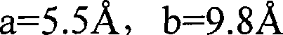
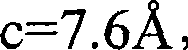


图24,25和26中,示出了Ba3MgSi2O8,Sr3MgSi2O8和Ca3MgSi2O8的X-射线衍射图(由粉末X-射线衍射数据基)。从这些晶体结构判断,允许形成固体溶液的包括Ba,Sr和Ca二价金属的组合物的范围较宽,它们具有相似的结构。以式[3]为代表的荧光体的结晶相,相应于通过用作为活化剂的Eu2+取代具有Ba3MgSi2O8,Sr3MgSi2O8或Ca3MgSi2O8结构的物质获得。In Figures 24, 25 and 26, the X-ray diffraction patterns of Ba 3 MgSi 2 O 8 , Sr 3 MgSi 2 O 8 and Ca 3 MgSi 2 O 8 (from powder X-ray diffraction data base) are shown. Judging from these crystal structures, there is a wide range of compositions including Ba, Sr and Ca divalent metals that allow the formation of solid solutions, which have similar structures. A crystal phase of a phosphor represented by formula [3], corresponding to a substance having a Ba 3 MgSi 2 O 8 , Sr 3 MgSi 2 O 8 , or Ca 3 MgSi 2 O 8 structure by substituting Eu 2+ as an activator get.
已知如Ba3MgSi2O8或Sr3MgSi2O8的结晶相,也已知Ba或Sr可以用其他的二价金属元素如Eu2+取代。本发明基于以下发现:当含有具有式[3]化学组合物(包括化学组合物如Ba3-xEuxMgSi2O8或Sr3-xEuxMgSi2O8)结晶相的荧光体暴露于来自第一光发射体的350-415nm光时,其发射具有比其他的荧光体显著较高的强度光。该上述荧光体产生的光具有比蓝光发射BaMgAl10O17:Eu或黄光发射Y3Al5O12:Ce压倒性的高强度。Crystal phases such as Ba 3 MgSi 2 O 8 or Sr 3 MgSi 2 O 8 are known, and it is also known that Ba or Sr can be replaced by other divalent metal elements such as Eu 2+ . The present invention is based on the discovery that when a phosphor containing a crystalline phase having a chemical composition of formula [3] (including chemical compositions such as Ba 3-x Eu x MgSi 2 O 8 or Sr 3-x Eu x MgSi 2 O 8 ) is exposed For 350-415 nm light from the first light emitter, it emits light with significantly higher intensity than the other phosphors. The light generated by the above phosphor has an overwhelmingly higher intensity than that of blue-emitting BaMgAl 10 O 17 :Eu or yellow-emitting Y 3 Al 5 O 12 :Ce.
含有式[3]结晶相的荧光体被来自第一光发射体的350-415nm光激发并产生具有显著高发光强度的可见光。The phosphor containing the crystalline phase of formula [3] is excited by 350-415 nm light from the first light emitter and generates visible light with remarkably high luminous intensity.
<模式4><
EuoM8 p(PO4)q(BO3)2-qZr [4]Eu o M 8 p (PO 4 ) q (BO 3 ) 2-q Z r [4]
M8表示具有至少一个价但除Eu,P和B之外的金属元素。考虑到色彩保留性能,发光强度等,它表示含有Ca,同时含有Ca和Mg总量为80mol%或更多的金属元素。含在M8中的Ca和Mg总量中Ca的比例优选为40mol%或更多。更加优选M8为至少一个选自Ca和Mg的元素,和含有至少40mol%的Ca。M 8 represents metal elements with at least one valence but other than Eu, P and B. In consideration of color retention performance, luminous intensity, etc., it means that Ca is contained, and a metal element containing Ca and Mg in a total amount of 80 mol% or more is contained. The ratio of Ca to the total amount of Ca and Mg contained in M8 is preferably 40 mol% or more. More preferably M8 is at least one element selected from Ca and Mg, and contains at least 40 mol% Ca.
当除Ca和Mg之外的金属元素被作为M8加入到晶体中时,没有对金属元素种类的具体限制。然而理想地,加入具有与Ca和Mg相同价的金属元素,即,二价金属元素如Sr,Zn,Ba,Pb或Sn,优选Sr,Zn或Ba,因为其协助保持晶体结构。少量的一价,三价,四价,五价或六价金属元素可以作为M中的金属元素引入,其目的是加速复合氧化物的结晶,其为烧结时二价金属元素和发光中心Eu2+在固体中的扩散导致。When a metal element other than Ca and Mg is added to the crystal as M 8 , there is no specific limitation on the kind of metal element. Ideally, however, a metal element having the same valence as Ca and Mg, ie, a divalent metal element such as Sr, Zn, Ba, Pb or Sn, preferably Sr, Zn or Ba is added because it assists in maintaining the crystal structure. A small amount of monovalent, trivalent, tetravalent, pentavalent or hexavalent metal elements can be introduced as metal elements in M, the purpose of which is to accelerate the crystallization of composite oxides, which are divalent metal elements and luminescent centers Eu2 during sintering + Diffusion leads in solids.
在一个实例中,Eu0.15Ca2.85(PO4)2荧光体中部分Ca2+可以用等摩尔量的Li+和Ga3+取代,同时保持电荷补偿效应。它也可能是用作为敏化剂的金属元素取代,目的是控制发光波长或发光强度。In one example, part of Ca 2+ in the Eu 0.15 Ca 2.85 (PO 4 ) 2 phosphor can be replaced with equimolar amounts of Li + and Ga 3+ while maintaining the charge compensation effect. It may also be substituted with a metal element as a sensitizer in order to control the emission wavelength or intensity.
Z表示除PO4 3-和BO3 3-之外的阴离子基团,特定的实例包括氢氧根离子(OH-),金属氧化物阴离子和卤素离子。金属氧化物阴离子包括SiO4 4-,SiO3 2-,TiO3 2-和ZrO3 2-,而卤素离子包括F-,Cl-,Br-和I-。然而实例不限于此。Z represents an anion group other than PO 4 3- and BO 3 3- , and specific examples include hydroxide ions (OH − ), metal oxide anions, and halide ions. Metal oxide anions include SiO 4 4- , SiO 3 2- , TiO 3 2- and ZrO 3 2- , while halide ions include F − , Cl − , Br − and I − . However, examples are not limited thereto.
考虑到色彩保留性能和发光强度,式[4]中Eu摩尔比率o为0.003或更大,优选0.015或更大。其上限为2.1或更少,优选1或更少。当用作发射中心离子的Eu2+摩尔比率o太小时,发光强度趋向于降低。The Eu molar ratio o in formula [4] is 0.003 or more, preferably 0.015 or more, in consideration of color retention performance and luminous intensity. The upper limit thereof is 2.1 or less, preferably 1 or less. When the molar ratio o of Eu 2+ serving as an emission center ion is too small, the luminous intensity tends to decrease.
当其太大时,在另一方面,由于称为浓度猝灭的现象发光强度也趋向于降低。When it is too large, on the other hand, the luminous intensity also tends to decrease due to a phenomenon called concentration quenching.
p为满足2.7≤(o+p)≤3.3的数字。在式[4]的基本晶体EuoM8 p(PO4)q(BO3)2-qZr中,当Z作为杂质忽略时,基础的化学计量的摩尔比率(o+p)为3。出现一些阳离子缺乏或阴离子缺乏,对本发明所要的荧光性能具有小的影响,使得(o+p)可以在上述范围内使用。p is a number satisfying 2.7≤(o+p)≤3.3. In the basic crystal Eu o M 8 p (PO 4 ) q (BO 3 ) 2-q Z r of formula [4], when Z is ignored as an impurity, the basic stoichiometric molar ratio (o+p) is 3 . Occurrence of some cation deficiencies or anion deficiencies has little effect on the desired fluorescence properties of the present invention, so that (o+p) can be used within the above range.
PO4基团的摩尔比率q代表满足1.2≤q≤2的数字。考虑到色彩保留性能,发光强度等,q优选1.6或更大。在上述式[4]中,用作主要阴离子的PO4和BO3基团总的摩尔比率为2。BO3基团的存在不会对色彩保留性能,发光强度等具有严重的不利影响。The molar ratio q of PO groups represents a number satisfying 1.2≤q≤2. In consideration of color retention performance, luminous intensity, etc., q is preferably 1.6 or greater. In the above formula [4], the total molar ratio of PO 4 and BO 3 groups serving as the main anion is 2. The presence of BO3 groups does not have serious adverse effects on color retention properties, luminous intensity, etc.
除PO4和BO3基团之外的阴离子Z的摩尔比率r数字满足0≤r≤0.1。如果其量不是足够的大到对本发明所要的荧光性能有不利地影响,阴离子Z可以合并入晶体中。它的量越小越好。r优选0.05或更少。The molar ratio r numbers of anions Z other than PO4 and BO3 groups satisfy 0≤r≤0.1. The anion Z can be incorporated into the crystal if the amount is not large enough to adversely affect the desired fluorescence properties of the present invention. The smaller the amount, the better. r is preferably 0.05 or less.
具有作为结晶基体和用Eu2+活化的正磷酸盐A3(PO4)2(其中A表示碱土金属)的物质已知为在254nm激发的普通荧光体。然而本发明基于以下发现:依赖于A3(PO4)2的碱土金属A的种类,由400nm左右光激发导致的发光强度和其发射峰半值宽度有巨大的差别;含有Ca或Ca-Mg复合阳离子作为A的A3(PO4)2:Eu2+物质,暴露于350-415nm激发光下发射具有高的发光强度的蓝光;相应于色彩保留性能巨大改善的发光波长-发光强度分布较宽,换言之,半值宽度大使得荧光体能够提供高的色彩保留性能。Substances with orthophosphate A 3 (PO 4 ) 2 (where A represents an alkaline earth metal) as a crystalline matrix and activated with Eu 2+ are known as common phosphors excited at 254 nm. However, the present invention is based on the following findings: depending on the type of alkaline earth metal A of A 3 (PO 4 ) 2 , there is a huge difference in the luminous intensity caused by photoexcitation around 400 nm and the half-value width of its emission peak; containing Ca or Ca-Mg As A 3 (PO 4 ) 2 :Eu 2+ species of A, the composite cation emits blue light with high luminous intensity when exposed to 350-415nm excitation light; the luminous wavelength-luminous intensity distribution corresponding to the greatly improved color retention performance is relatively Wide, in other words, a large half-value width enables the phosphor to provide high color retention properties.
将要在本发明中使用的荧光体可以通过干法制备粉碎的混合物获得,更特别地,通过在干粉碎机中如锤式粉碎机,辊式粉碎机,球磨机或喷射研磨机粉碎以下化合物获得:当荧光体含有式[1]的结晶相时,作为M1源,X源,PO4源和Sr源的化合物和作为发射中心离子(Eu)元素源的化合物;当荧光体含有式[2]的结晶相时,作为M2源,M2’源,M3源,M3’源,M4源和M4’源的化合物和作为发射中心离子(Eu2+)元素源的化合物;当荧光体含有式[3]结晶相时,作为M5源,M6源和M7源化合物和作为发射中心离子(Eu2+)元素源的化合物;或当荧光体含有式[4]结晶相时,作为M8源,PO4源,BO3源和Z源的化合物以及作为发射中心离子(Eu2+)元素源的化合物;然后在混合机中混合粉碎的产物,如带式共混机,双筒混合机或Henschel混合机,或混合和粉碎的次序相反;或湿法制备粉碎的混合物,更特别地,通过把相应的化合物加入介质(如水)中,在湿粉碎机如介质-搅拌型粉碎机中粉碎或混合所得混合物,或在干粉碎机中粉碎相应化合物,用介质如水混合粉碎产物以制备相应的浆然后通过喷雾干燥等干燥该浆;和接着通过加热烧结该因此制得的粉碎的混合物。The phosphor to be used in the present invention can be obtained by dry preparation of a pulverized mixture, more particularly, by pulverizing the following compounds in a dry pulverizer such as a hammer mill, a roll mill, a ball mill or a jet mill: When phosphor contains the crystalline phase of formula [1], as M 1 source, X source, the compound of PO 4 source and Sr source and as the compound of emission center ion (Eu) element source; When phosphor contains formula [2] When the crystalline phase is used as M 2 source, M 2' source, M 3 source, M 3' source, M 4 source and M 4' source compound and the compound as emission center ion (Eu 2+ ) element source; when When the phosphor contains the crystalline phase of formula [3], as M 5 source, M 6 source and M 7 source compound and as the compound of the emission center ion (Eu 2+ ) element source; or when the phosphor contains the formula [4] crystalline phase When, as the compound of M 8 source, PO 4 source, BO 3 source and Z source and as the source of emission center ion (Eu 2+ ) element; then mix the pulverized product in a mixer, such as a ribbon blender , a twin-drum mixer or a Henschel mixer, or the reverse order of mixing and pulverization; or wet preparation of pulverized mixtures, more particularly, by adding the corresponding compound to a medium (such as water) in a wet pulverizer such as medium-stirring Pulverize or mix the resulting mixture in a type pulverizer, or pulverize the corresponding compound in a dry pulverizer, mix the pulverized product with a medium such as water to prepare a corresponding slurry and then dry the slurry by spray drying or the like; and then sinter the thus prepared by heating Crush the mixture.
这些粉碎和混合方法中,因为将要加入的少量化合物,如作为发光中心离子元素源的化合物必须均匀混合和分散,优选使用液体介质。对于作为其他元素源的化合物也优选后者湿方法,因为它能够制备它们的均匀混合物。Of these pulverizing and mixing methods, since a small amount of compound to be added, such as a compound serving as a source of an ion element for a luminescence center, must be uniformly mixed and dispersed, a liquid medium is preferably used. The latter wet method is also preferred for compounds that are sources of other elements, since it enables the preparation of homogeneous mixtures of them.
在耐热的容器如氧化铝或石英坩锅或碟子中进行加热,通常在700-1700℃,优选900-1500℃在单独气体的气氛中如空气,氧,一氧化碳,二氧化碳,氮气,氢气或氩气,或其混合物中加热10分钟到24小时。加热之后按需要紧接着洗涤,干燥和分类。Heating is carried out in a heat-resistant container such as an alumina or quartz crucible or dish, usually at 700-1700°C, preferably 900-1500°C in an atmosphere of a single gas such as air, oxygen, carbon monoxide, carbon dioxide, nitrogen, hydrogen or argon gas, or a mixture thereof, for 10 minutes to 24 hours. The heating is followed by washing, drying and sorting as required.
当加热时,为获得足够的贡献光发射的发射中心离子元素离子状态(价数),选择必要的气氛。当作为本发明中Eu元素是二价时,优选中性的或还原的大气如一氧化碳,氮气,氢气或氩气,但在适当选择的条件下,氧化性气氛如空气或氧气也可以采用。When heated, the necessary atmosphere is chosen to obtain sufficient emission center ion element ion states (valences) to contribute to light emission. When the element Eu is divalent in the present invention, a neutral or reducing atmosphere such as carbon monoxide, nitrogen, hydrogen or argon is preferred, but an oxidizing atmosphere such as air or oxygen may also be used under suitably selected conditions.
作为M1到M8源,M2’到M4’源,Sr源和Eu源化合物的实例包括M1-M8,M2’-M4’,Sr和Eu的氧化物,氢氧化物,碳酸盐,硝酸盐,硫酸盐,草酸盐,羧酸盐,卤化物,磷酸氢盐和磷酸盐。As M 1 to M 8 source, M 2' to M 4' source, Sr source and Eu source compound examples include M 1 -M 8 , M 2' -M 4' , oxides, hydroxides of Sr and Eu , carbonates, nitrates, sulfates, oxalates, carboxylates, halides, hydrogenphosphates and phosphates.
作为Sr源的化合物的特定实例包括:SrO,Sr(OH)2·8H2O,SrCO3,Sr(NO3)2,Sr(OCO)2·H2O,Sr(OCOCH3)2·0.5H2O和SrCl2。Specific examples of the compound as the Sr source include: SrO, Sr(OH) 2 .8H 2 O, SrCO 3 , Sr(NO 3 ) 2 , Sr(OCO) 2 .H 2 O, Sr(OCOCH 3 ) 2 .0.5 H 2 O and SrCl 2 .
作为Ba源的化合物的特定实例包括:BaO,Ba(OH)2·8H2O,BaCO3,Ba(NO3)2,BaSO4,Ba(OCO)2·2H2O,Ba(OCOCH3)2和BaCl2。Specific examples of the compound as the Ba source include: BaO, Ba(OH) 2 .8H 2 O, BaCO 3 , Ba(NO 3 ) 2 , BaSO 4 , Ba(OCO) 2 .2H 2 O, Ba(OCOCH 3 ) 2 and BaCl 2 .
作为Mg源的化合物的特定实例包括:MgO,Mg(OH)2,MgCO3,Mg(OH)2,3MgCO3·3H2O,Mg(NO3)2·6H2O,Mg(OCO)2·2H2O,Mg(OCOCH3)2·4H2O,和MgCl2。Specific examples of compounds that are sources of Mg include: MgO, Mg(OH) 2 , MgCO 3 , Mg(OH) 2 , 3MgCO 3 3H 2 O, Mg(NO 3 ) 2 6H 2 O, Mg(OCO) 2 • 2H 2 O, Mg(OCOCH 3 ) 2 • 4H 2 O, and MgCl 2 .
作为Ca源的化合物的特定实例包括:CaO,Ca(OH)2,CaCO3,Ca(NO3)2·4H2O,Ca(OCO)2·H2O,Ca(OCOCH3)2·H2O,和CaCl2。Specific examples of compounds as Ca sources include: CaO, Ca(OH) 2 , CaCO 3 , Ca(NO 3 ) 2 .4H 2 O, Ca(OCO) 2 .H 2 O, Ca(OCOCH 3 ) 2 .H 2 O, and CaCl 2 .
作为Zn源的化合物的特定实例包括:ZnO,Zn(OH)2,ZnCO3,Zn(NO3)2·6H2O,Zn(OCO)2,Zn(OCOCH3)2和ZnCl2。Specific examples of the compound as the Zn source include: ZnO, Zn(OH) 2 , ZnCO 3 , Zn(NO 3 ) 2 ·6H 2 O, Zn(OCO) 2 , Zn(OCOCH 3 ) 2 and ZnCl 2 .
作为Mn源的化合物的特定实例包括:MnO2,Mn2O3,Mn3O4,MnOOH,MnCO3,Mn(NO3)2,Mn(OCOCH3)2·2H2O,Mn(OCOCH3)3·nH2O,和MnCl2·4H2O。Specific examples of compounds that are sources of Mn include: MnO 2 , Mn 2 O 3 , Mn 3 O 4 , MnOOH, MnCO 3 , Mn(NO 3 ) 2 , Mn(OCOCH 3 ) 2 .2H 2 O, Mn(OCOCH 3 ) 3 ·nH 2 O, and MnCl 2 ·4H 2 O.
作为Eu2+元素源的化合物的特定实例包括:Eu2O3,Eu(OCOCH3)3·4H2O,EuCl3·6H2O和Eu2(OCO)3·6H2O。Specific examples of the compound as the source of the Eu 2+ element include: Eu 2 O 3 , Eu(OCOCH 3 ) 3 .4H 2 O, EuCl 3 .6H 2 O, and Eu 2 (OCO) 3 .6H 2 O.
作为PO4源的化合物实例包括:M1,M8,Eu和NH4的磷酸氢盐,磷酸盐,偏磷酸盐,焦磷酸盐,P2O5,PX3,PX5,M2PO4X,磷酸,偏磷酸和焦磷酸。Examples of compounds that are sources of PO include: hydrogen phosphate, phosphate, metaphosphate, pyrophosphate, P 2 O 5 , PX 3 , PX 5 , M 2 PO 4 of M 1 , M 8 , Eu and NH 4 X, phosphoric acid, metaphosphoric acid and pyrophosphoric acid.
作为BO3源的化合物实例包括:M8,Eu和NH4的硼酸盐,硼酸氢盐,四硼酸盐,八硼酸盐(octaborate),二硼酸盐,和五硼酸盐,硼酸和氧化硼。其中,优选M8,Eu和NH4的硼酸盐和氢硼酸盐,硼酸和氧化硼。Examples of compounds that are sources of BO include: borates , hydrogen borates, tetraborates, octaborates, diborates, and pentaborates of M8, Eu, and NH4 , boric acid and boron oxide. Among them, borates and hydroborates of M 8 , Eu and NH 4 , boric acid and boron oxide are preferred.
作为X源的化合物实例包括M1X,NH4X,HX和M1 2PO4X。Examples of the compound as the source of X include M 1 X, NH 4 X, HX and M 1 2 PO 4 X.
作为Z源的化合物实例包括M8 2SiO4,M8SiO3,M8TiO3,M8ZnO3,M8F2,M8Cl2,M8Br2,NH4F,NH4Cl,NH4Br,HF,HCl和HBr。Examples of compounds as Z sources include M 8 2 SiO 4 , M 8 SiO 3 , M 8 TiO 3 , M 8 ZnO 3 , M 8 F 2 , M 8 Cl 2 , M 8 Br 2 , NH 4 F, NH 4 Cl , NH4Br , HF, HCl and HBr.
这些化合物中,考虑到化学组成,反应活性和烧结时不放出气体如NOx和SOx而选择合适的化合物。Among these compounds, suitable compounds are selected in consideration of chemical composition, reactivity and non-emission of gases such as NOx and SOx upon sintering.
本发明中,对荧光体发射光的第一光发射体具有发射波长为350-415nm的光。优选在波长范围350-415nm内产生峰波长的光发射体。考虑到发光效率,更加优选在波长范围390-410nm内产生峰波长的光发射体。第一光发射体特定的实例包括发光二极管(LED)和激光二极管(LD)。更加优选激光二极管,因为其消耗较少能量。In the present invention, the first light emitter that emits light to the phosphor has light with an emission wavelength of 350-415 nm. Light emitters producing peak wavelengths in the wavelength range 350-415 nm are preferred. In consideration of luminous efficiency, a light emitter that produces a peak wavelength within the wavelength range of 390-410 nm is more preferred. Specific examples of first light emitters include light emitting diodes (LEDs) and laser diodes (LDs). Laser diodes are more preferred because they consume less power.
其中,基于GaN的LED和使用GaN系化合物半导体的LD特别地优选,因为它们的发光输出或外量子效率大于目前在该区域发光的基于SiC的LED,使得通过与上述荧光体结合使用,在相当低的电流下得到很明亮的光发射。例如,当施加20mA电流时,基于GaN的二极管具有至少100倍基于SiC的二极管的发光强度。基于GaN的LED或LD优选作为AlXGaYN发光层,GaN发光层或InXGaYN发光层。具有InXGaYN发光层的基于GaN的LED特别地优选,因为其具有显著高的发光强度,同时具有多个InXGaYN层和GaN层量子阱结构的基于GaN的LD特别地优选,因为其显著高的发光强度。Among them, GaN-based LEDs and LDs using GaN-based compound semiconductors are particularly preferable because their luminous output or external quantum efficiency is greater than that of SiC-based LEDs currently emitting light in this region, so that by using in combination with the above-mentioned phosphors, they can be used in a comparable Very bright light emission is obtained at low currents. For example, a GaN-based diode has at least 100 times the luminous intensity of a SiC-based diode when a current of 20 mA is applied. GaN-based LEDs or LDs are preferred as AlXGaYN light-emitting layers, GaN light-emitting layers or InXGaYN light - emitting layers. A GaN -based LED with an InXGaYN light-emitting layer is particularly preferred because it has a remarkably high luminous intensity, while a GaN-based LD with multiple InXGaYN layers and a GaN layer quantum well structure is particularly preferred , because of its remarkably high luminous intensity.
在上述化合物中,X+Y通常值在范围0.8-1.2内。作为基于GaN的LED,优选其中发光层中掺杂有Zn或Si或没有掺杂剂,因为它协助控制发光性能。该基于GaN的LED具有如下发光层:p层,n层,电极和基底作为基本构成,其具有异质结构,其中因为具有高度发光效率,优选发光层被夹在n型和p型AlXGaYN层,GaN层或InXGaYN层之间;更加优选其作为异质结构具有量子阱结构,因为具有更高的发光效率。In the above compounds, X+Y typically has a value in the range 0.8-1.2. As a GaN-based LED, one in which the light-emitting layer is doped with Zn or Si or no dopant is preferred because it assists in controlling light-emitting properties. This GaN-based LED has the following light emitting layers: p layer, n layer, electrode and substrate as basic constituents, which have a heterostructure in which it is preferable that the light emitting layer is sandwiched between n-type and p-type Al X Ga Y N layers, between GaN layers or In X Ga Y N layers; it is more preferable that it has a quantum well structure as a heterostructure because it has higher luminous efficiency.
本发明中,使用面发光型光发射器(vertival cavity surface emitingemitter),特别地优选垂直腔表面光发射型GaN系激光二极管作为第一光发射体,其目的是提高整个光发射设备的发光效率。该面发光型器在膜平面方向产生强的光。在垂直腔表面型基于GaN的激光二极管中,通过成功地控制发光层的晶体生长同时利用反射层,在平面方向的光发射可以比在发光层的边缘方向更强。当使用面发光型二极管时,光发射截面积每单位发光量可以大于从发光层边缘发光的二极管。In the present invention, a vertical cavity surface emitting emitter (vertival cavity surface emitting emitter), especially a vertical cavity surface emitting GaN laser diode is preferably used as the first light emitter, the purpose of which is to improve the luminous efficiency of the entire light emitting device. This surface emitting device generates intense light in the film plane direction. In vertical-cavity surface-type GaN-based laser diodes, by successfully controlling the crystal growth of the light-emitting layer while utilizing the reflective layer, light emission in the planar direction can be stronger than in the edge direction of the light-emitting layer. When a surface emitting type diode is used, the amount of light emitted per unit of the light emitting cross-sectional area may be larger than that of a diode that emits light from the edge of the light emitting layer.
作为结果,当构成第二光发射体的荧光体暴露于光时,在相同光强度下暴露的面积可以显著地增大,意味着辐射效率的改善。作为结果,得到来自荧光体的更强的光。As a result, when the phosphor constituting the second light emitter is exposed to light, the exposed area at the same light intensity can be significantly increased, meaning improvement in radiation efficiency. As a result, stronger light from the phosphor is obtained.
当面发光型型被用作第一光发射体时,第二光发射体优选为膜形式。面发光型型光发射体具有大的光发射截面积,使得在截面方向膜形式的第二光发射体的形成可能提高来自荧光体的发光强度,因为每单位荧光体量的从第一光发射体到荧光体的辐射截面积变大的。When a surface emission type is used as the first light emitter, the second light emitter is preferably in the form of a film. The surface-emitting type light emitter has a large light emission cross-sectional area, so that the formation of the second light emitter in the form of a film in the cross-sectional direction may increase the luminous intensity from the phosphor, because the amount of light emitted from the first light per unit phosphor amount The radiation cross-sectional area from the body to the phosphor becomes larger.
当面发光型型被用作第一光发射体和使用膜形式的第二光发射体时,优选使膜形式的第二光发射体与第一光发射体的光发射表面直接接触。此处所用的术语“使得直接接触”意思是“使第一光发射体与第二光发射体紧密接触而没有空气或其他的气体嵌入到它们之间”。When the surface emission type is used as the first light emitter and the second light emitter in the form of a film is used, it is preferable to bring the second light emitter in the form of a film into direct contact with the light emitting surface of the first light emitter. The term "bringing direct contact" used herein means "bringing the first light emitter and the second light emitter into close contact without air or other gas intercalated therebetween".
作为结果,它可能避免光能的损失,否则会由于被第二光发射体的膜表面反射来自第一光发射体的光和泄漏到外面而发生,从而改善整个器件的发光效率。As a result, it is possible to avoid loss of light energy, which would otherwise occur due to reflection of light from the first light emitter by the film surface of the second light emitter and leakage to the outside, thereby improving luminous efficiency of the entire device.
图2为示意性示出本发明光发射器件的一个实施例中的第一光发射体和第二光发射体之间位置关系的透视图,其中数字1指示的是具有荧光体的膜形式的第二光发射体,2为作为第一光发射体的面发光型的基于GaN的LD,和3为基底。这三个组件可以通过使LD 2和第二光发射体1的表面接触而相互接触,LD 2和第二光发射体1在先单独制备,通过各种方式包括粘合剂使它们的表面接触;或者在LD 2的发光表面形成(作为膜)或模制第二光发射体。作为结果,LD 2可以与第二光发射体1接触。Figure 2 is a perspective view schematically showing the positional relationship between the first light emitter and the second light emitter in one embodiment of the light emitting device of the present invention, wherein numeral 1 indicates a film form with a phosphor The second light emitter, 2 is a surface emission type GaN-based LD as the first light emitter, and 3 is a substrate. These three components can be brought into contact with each other by bringing the surfaces of the
来自第一光发射体或第二光发射体的光通常在所有的方向散射。当要用作第二光发射体的荧光体粉末分散入树脂时,部分光当其来到树脂外时被反射,使得光可以一定程度上调节成一个方向。因此光一定程度上能被引入到有效的方向,使得优选使用树脂中的荧光体粉末分散物作为第二光发射体。作为荧光体粉末,通常应用具有平均颗粒尺寸为0.5-15μm的粉末。为了有效地利用来自第一光发射体的光,平均直径优选为0.8-5μm,更加优选0.8-2μm。Light from either the first light emitter or the second light emitter is generally scattered in all directions. When the phosphor powder to be used as the second light emitter is dispersed into the resin, part of the light is reflected when it comes out of the resin, so that the light can be tuned in one direction to some extent. Light can thus be guided to an effective direction to a certain extent, so that it is preferable to use a dispersion of phosphor powder in a resin as the second light emitter. As the phosphor powder, a powder having an average particle size of 0.5-15 μm is generally used. In order to effectively utilize light from the first light emitter, the average diameter is preferably 0.8-5 μm, more preferably 0.8-2 μm.
使用树脂中的荧光体分散物具有其他的优势在于其提高来自第二光发射体的光强度,因为被来自第一光发射体的光照射的第二光发射体总面积变大。用于该目的的树脂的实例包括:环氧树脂,聚乙烯基树脂,聚乙烯树脂,聚丙烯树脂和聚酯树脂。优选环氧树脂,因为荧光体粉末可以更好地在其中分散。当荧光体粉末在树脂中分散时,荧光体粉末对整个树脂的重量比通常为10-95%,优选20-90%,更加优选30-80%。当荧光体的量太大时,发生粉末团聚而降低发光效率,但是太少量由于在树脂中的光吸收或散射而弱化发光效率。Using a phosphor dispersion in a resin has the further advantage that it increases the light intensity from the second light emitter, since the total area of the second light emitter illuminated by the light from the first light emitter becomes larger. Examples of resins used for this purpose include epoxy resins, polyvinyl resins, polyethylene resins, polypropylene resins and polyester resins. Epoxy resins are preferred because the phosphor powder can be better dispersed therein. When the phosphor powder is dispersed in the resin, the weight ratio of the phosphor powder to the entire resin is usually 10-95%, preferably 20-90%, more preferably 30-80%. When the amount of the phosphor is too large, powder agglomeration occurs to lower luminous efficiency, but too small amount weakens luminous efficiency due to light absorption or scattering in the resin.
通过混合来自第一光发射体的光和来自第二光发射体的光,本发明的光发射器件能够发射白光。当发光时,可以按需要使用色彩滤镜。通过使得来自器件的光变白,目标是暴露于该光发射器件的光具有高的色彩保留性能。当应用该光发射器件作为照明使用时,这一点很重要。The light emitting device of the present invention can emit white light by mixing light from the first light emitter and light from the second light emitter. When glowing, color filters can be used as desired. By whitening the light from the device, the goal is for light exposed to the light emitting device to have high color retention properties. This is important when applying the light emitting device for use as lighting.
本发明的光发射器件由作为波长转换材料的上述荧光体和产生350-415nm光的光发射体构成。在该器件中,荧光体吸收光发射体产生的350-415nm光,由此可以在任何使用环境下,发射具有良好色彩保留性能和高强度的可见光。它适合作为作为背光源,交通信号光源,和成像显示器器件,如有色液晶显示器或面发光型照明器,的光源。The light-emitting device of the present invention is composed of the above-mentioned phosphor as a wavelength conversion material and a light emitter that generates light of 350-415 nm. In the device, the phosphor absorbs the 350-415nm light generated by the light emitter, so that visible light with good color retention and high intensity can be emitted in any use environment. It is suitable as a light source for backlight sources, traffic signal light sources, and imaging display devices such as colored liquid crystal displays or surface emitting illuminators.
本发明的光发射器件将参照图表在以下描述。图3为示意性的截面图,其示出具有第一光发射体(发射350-415nm的光)和第二光发射体的光发射器件的一个实施例,其中数字4指示的是光发射器件,5为装配引线(mountlead),6为内引线,7为第一光发射体(其发射350-415nm的光),8为作为第二光发射体的含有荧光体的树脂部分,9为导体配线和10模制构件。The light-emitting device of the present invention will be described below with reference to the diagrams. Figure 3 is a schematic cross-sectional view showing an embodiment of a light-emitting device with a first light emitter (emitting light at 350-415nm) and a second light emitter, where numeral 4 indicates a light-emitting device , 5 is the assembly lead (mountlead), 6 is the inner lead, 7 is the first light emitter (it emits light of 350-415nm), 8 is the resin part containing the phosphor as the second light emitter, and 9 is the conductor wiring and 10 molded components.
图3中示出的本发明一个实施例的光发射器件具有类似子弹的形状。在装配引线5的上部盖子中,第一光发射体(350-415nm光的发射器)7通过含有荧光体的树脂部分8而固定,该含荧光体的树脂部分8作为第二光发射体形成,其通过在粘合剂如环氧树脂或丙烯酸酯树脂中混合和分散荧光体,接着在杯中涂覆该分散物而形成。第一光发射体7和装配引线5,和第一光发射体7和内引线6通过导体配线9相互电连接。它们都被由环氧树脂等制成的模制构件10覆盖和保护。The light emitting device of one embodiment of the present invention shown in FIG. 3 has a bullet-like shape. In the upper cover of the
在具有合并入其中的光发射器件1的面发光型照明器98中,许多的光发射器件91被置于四方形支持容器910的底表面上,四方形支持容器910具有不透明的内表面,例如,白色平坦的内表面,同时在该容器外布置有驱动该光发射器件91的电源和电路(未示出)。在相应于支持容器910盖子的位置上,固定有扩散板99如乳白色的丙烯酰板以得到均匀的光发射。In the surface-emitting illuminator 98 having the light-emitting
面发光型照明器98被接通,电压被施加到光发射器件91的第一光发射体上,由此发射350-415nm的光。作为第二光发射体的含有荧光体的树脂部分中的荧光体吸收部分光并发射可见光。可见光与蓝光等不被该荧光体吸收的光混合。所得到的具有高的色彩保留性能的光穿透扩散板99,在该图的上部方向输出,由此在支持容器910的扩散板99的平面中,得到具有均匀亮度的光。The surface emitting illuminator 98 is turned on, and voltage is applied to the first light emitter of the
实施例Example
下文中将更详细地描述本发明。然而,应当明白在不偏离本发明范围内,本发明并不被下述实施例限制。Hereinafter, the present invention will be described in more detail. However, it should be understood that the present invention is not limited by the following examples without departing from the scope of the present invention.
在实施例1-10,12-17和对比实施例1和2中,相对发光强度(i)是假定对比实施例1中获得的荧光体的发光强度为100时的值。在实施例19-23和对比实施例3中,相对发光强度(i)是假定各自在400nm和254nm激发对比实施例3所获得的荧光体发光强度为100时的值。在实施例25-35和对比实施例4和5中,相对发光强度(i)是假定对比实施例4中获得的荧光体的发光强度为100时的值。在实施例37-44和对比实施例6中,相对积分强度是假定对比实施例6中获得的荧光体的积分强度为1时的值。在实施例37-41,和45-47中,相对发光强度(i)是假定各自在400nm和254nm激发实施例40所获得的荧光体发光强度为100时的值。In Examples 1-10, 12-17 and Comparative Examples 1 and 2, the relative luminous intensity (i) is a value assuming that the luminous intensity of the phosphor obtained in Comparative Example 1 is 100. In Examples 19-23 and Comparative Example 3, the relative luminous intensity (i) is a value assuming that the luminous intensity of the phosphor obtained in Comparative Example 3 excited at 400 nm and 254 nm is 100, respectively. In Examples 25 to 35 and Comparative Examples 4 and 5, the relative luminous intensity (i) is a value assuming that the luminous intensity of the phosphor obtained in Comparative Example 4 is 100. In Examples 37-44 and Comparative Example 6, the relative integrated intensity is a value assuming that the integrated intensity of the phosphor obtained in Comparative Example 6 is 1. In Examples 37-41, and 45-47, the relative luminescence intensity (i) is a value assuming that the luminescence intensity of the phosphor obtained in Example 40 excited at 400 nm and 254 nm is 100, respectively.
实施例1Example 1
在由氧化铝制成和含有珠子的湿-型球磨机中,用纯水粉碎和混合0.1055摩尔SrHPO4,0.0352摩尔SrCO3,0.0176摩尔SrCl2和0.0088摩尔Eu2O3。干燥后,所得的混合物穿过尼龙网,在含有4%氢的氮气流下,该粉碎的混合物通过加热到1200℃在氧化铝坩锅中烧结2小时。该烧结的混合物接着用水洗涤,干燥和分级(classified),由此制得荧光体Sr4.5Eu0.5(PO4)3Cl。In a wet-type ball mill made of alumina and containing beads, 0.1055 mol of SrHPO 4 , 0.0352 mol of SrCO 3 , 0.0176 mol of SrCl 2 and 0.0088 mol of Eu 2 O 3 were pulverized and mixed with pure water. After drying, the resulting mixture was passed through a nylon mesh, and the pulverized mixture was sintered in an alumina crucible by heating to 1200° C. for 2 hours under a nitrogen flow containing 4% hydrogen. The sintered mixture was then washed with water, dried and classified, whereby phosphor Sr 4.5 Eu 0.5 (PO 4 ) 3 Cl was produced.
该荧光体所得到的X-射线衍射图显示于图4中。从图中,发现图4的峰的式样在晶体学上等同于图1的Sr5(PO4)3Cl。The obtained X-ray diffraction pattern of the phosphor is shown in FIG. 4 . From the figure, it was found that the pattern of the peaks of FIG. 4 was crystallographically equivalent to that of Sr 5 (PO 4 ) 3 Cl of FIG. 1 .
图5显示了所得到的荧光体在400nm激发的发光光谱,该波长为GaN发光二极管在紫外区域主要的波长。Fig. 5 shows the emission spectrum of the obtained phosphor excited at 400nm, which is the main wavelength of GaN light-emitting diodes in the ultraviolet region.
在表1中,示出了当所得到的荧光体在400nm激发时的发射峰波长和相对发光强度(i),即,400nm为GaN发光二极管在紫外区域主要的波长;和利用反射率为98%的反射镜测量的该荧光体量子吸收效率αq以及荧光体量子吸收效率αq和内量子效率ηi的乘积αq·ηi。In Table 1, the emission peak wavelength and relative luminous intensity (i) when the obtained phosphor is excited at 400nm are shown, that is, 400nm is the main wavelength of GaN light-emitting diodes in the ultraviolet region; and using a reflectance of 98% The phosphor quantum absorption efficiency α q and the product α q ·η i of the phosphor quantum absorption efficiency α q and internal quantum efficiency η i measured by the mirror.
关于Sr(5-x)Eux(PO4)3Cl,由x和基于六方体系的晶格常数计算的晶胞体积,该六方体系的晶格常数为:
实施例2Example 2
除了使用0.1055摩尔SrHPO4,0.0176摩尔SrCO3,0.0176摩尔SrCl2和0.0176摩尔Eu2O3作为原材料,按与实施例1类似的方式制得荧光体Sr4Eu1(PO4)3Cl。Phosphor Sr 4 Eu 1 (PO 4 ) 3 Cl was prepared in a similar manner to Example 1 except that 0.1055 moles of SrHPO 4 , 0.0176 moles of SrCO 3 , 0.0176 moles of SrCl 2 and 0.0176 moles of Eu 2 O 3 were used as raw materials.
所得到的荧光体的X-射线衍射图显示于图6中。从图中,发现图6的峰的式样在晶体学上等同于图1的Sr5(PO4)3Cl。The X-ray diffraction pattern of the obtained phosphor is shown in FIG. 6 . From the figure, it was found that the pattern of the peaks of FIG. 6 was crystallographically equivalent to that of Sr 5 (PO 4 ) 3 Cl of FIG. 1 .
所得到的荧光体在400nm下激发,400nm为GaN光发射二极管在紫外区域主要的波长。示出了它的发射峰波长,相对发光强度(i),利用反射率为98%的反射镜测量的该荧光体量子吸收效率αq以及荧光体量子吸收效率αq和内量子效率ηi的乘积αq·ηi。The obtained phosphor is excited at 400nm, which is the main wavelength of GaN light-emitting diodes in the ultraviolet region. Shown its emission peak wavelength, relative luminous intensity (i), utilize this phosphor quantum absorption efficiency α q that reflectivity 98% mirror measures and phosphor quantum absorption efficiency α q and internal quantum efficiency η i Product α q ·η i .
Eu-Eu平均距离为
实施例3Example 3
除了使用0.1055摩尔SrHPO4,0.0176摩尔SrCl2和0.0264摩尔Eu2O3作为原材料,按与实施例1类似的方式制得荧光体Sr3.5Eu1.5(PO4)3Cl。Phosphor Sr 3.5 Eu 1.5 (PO 4 ) 3 Cl was prepared in a similar manner to Example 1 except that 0.1055 moles of SrHPO 4 , 0.0176 moles of SrCl 2 and 0.0264 moles of Eu 2 O 3 were used as raw materials.
所得到的荧光体X-射线衍射图显示于图7中。从该图中,发现图7的峰的式样在晶体学上等同于图1的Sr5(PO4)3Cl。The obtained phosphor X-ray diffraction pattern is shown in FIG. 7 . From this figure, it was found that the pattern of the peaks of FIG. 7 was crystallographically equivalent to that of Sr 5 (PO 4 ) 3 Cl of FIG. 1 .
所得到的荧光体在400nm下激发,400nm为GaN光发射二极管在紫外区域主要的波长。示出了它的发射峰波长,相对发光强度(i),利用反射率为98%的反射镜测量的该荧光体量子吸收效率αq以及荧光体量子吸收效率αq和内量子效率ηi的乘积αq·ηi。The obtained phosphor is excited at 400nm, which is the main wavelength of GaN light-emitting diodes in the ultraviolet region. Shown its emission peak wavelength, relative luminous intensity (i), utilize this phosphor quantum absorption efficiency α q that reflectivity 98% mirror measures and phosphor quantum absorption efficiency α q and internal quantum efficiency η i Product α q ·η i .
Eu-Eu平均距离为
实施例4Example 4
除了0.0879摩尔SrHPO4,0.0176摩尔SrCl2,0.0352摩尔Eu2O3和0.0176摩尔(NH4)2HPO4作为原材料,按与实施例1类似的方式制得荧光体Sr3Eu2(PO4)3Cl。Except 0.0879 moles of SrHPO 4 , 0.0176 moles of SrCl 2 , 0.0352 moles of Eu 2 O 3 and 0.0176 moles of (NH 4 ) 2 HPO 4 as raw materials, the phosphor Sr 3 Eu 2 (PO 4 ) was prepared in a similar manner to Example 1. 3 Cl.
所得到的荧光体的X-射线衍射图显示于图8中。从图中,发现图8的峰的式样在晶体学上等同于图1的Sr5(PO4)3Cl。The X-ray diffraction pattern of the obtained phosphor is shown in FIG. 8 . From the figure, it was found that the pattern of the peaks of FIG. 8 was crystallographically equivalent to that of Sr 5 (PO 4 ) 3 Cl of FIG. 1 .
所得到的荧光体在400nm下激发,400nm为GaN光发射二极管在紫外区域主要的波长。在表1中示出了它的发射峰波长和相对发光强度(i)。The obtained phosphor is excited at 400nm, which is the main wavelength of GaN light-emitting diodes in the ultraviolet region. Its emission peak wavelength and relative luminous intensity (i) are shown in Table 1.
Eu-Eu平均距离为
实施例5Example 5
除了使用0.1055摩尔SrHPO4,0.0484摩尔SrCO3,0.0176摩尔SrCl2和0.00176摩尔CaCO3,碱式碳酸镁(0.00088摩尔按Mg)和0.00088摩尔Eu2O3作为原材料,按与实施例1类似的方式制得Sr4.875Ca0.05Mg0.025Eu0.05(PO4)3Cl。Except using 0.1055 moles of SrHPO 4 , 0.0484 moles of SrCO 3 , 0.0176 moles of SrCl 2 and 0.00176 moles of CaCO 3 , basic magnesium carbonate (0.00088 moles as Mg) and 0.00088 moles of Eu 2 O 3 were used as raw materials, in a manner similar to Example 1 Sr 4.875 Ca 0.05 Mg 0.025 Eu 0.05 (PO 4 ) 3 Cl is obtained.
所得到的荧光体的X-射线衍射图显示于图10中。从图中,发现图10的峰的式样在晶体学上等同于图1的Sr5(PO4)3Cl。所得到的荧光体在400nm下激发,400nm为GaN光发射二极管在紫外区域主要的波长,并测量它的发光光谱。在表1中,示出了它的发射峰波长,相对发光强度(i),利用反射率为98%的反射镜测量的该荧光体量子吸收效率αq以及荧光体量子吸收效率αq和内量子效率ηi的乘积αq·ηi。The X-ray diffraction pattern of the obtained phosphor is shown in FIG. 10 . From the figure, it was found that the pattern of the peaks of FIG. 10 was crystallographically equivalent to Sr 5 (PO 4 ) 3 Cl of FIG. 1 . The obtained phosphor was excited at 400nm, which is the main wavelength of the GaN light-emitting diode in the ultraviolet region, and its emission spectrum was measured. In Table 1, its emission peak wavelength, relative luminous intensity (i), the phosphor quantum absorption efficiency α q and the phosphor quantum absorption efficiency α q measured by a mirror with a reflectivity of 98% and internal The product α q ·η i of the quantum efficiency η i .
Eu-Eu平均距离为 Eu-Eu average distance is
实施例6Example 6
除了使用0.1055摩尔SrHPO4,0.0396摩尔SrCO3,0.00879摩尔BaCO3,碱式碳酸镁(0.00264摩尔按Mg),0.0176摩尔BaCl2,和0.00088摩尔Eu2O3作为原材料,按与实施例1类似的方式制得荧光体Sr4.125Ba0.75Mg0.075Eu0.05(PO4)3Cl。Except using 0.1055 moles of SrHPO 4 , 0.0396 moles of SrCO 3 , 0.00879 moles of BaCO 3 , basic magnesium carbonate (0.00264 moles by Mg), 0.0176 moles of BaCl 2 , and 0.00088 moles of Eu 2 O 3 were used as raw materials, and were similar to Example 1. Phosphor Sr 4.125 Ba 0.75 Mg 0.075 Eu 0.05 (PO 4 ) 3 Cl was prepared by this method.
所得到的荧光体的X-射线衍射图显示于图11中。从图中,发现图11的峰的式样在晶体学上等同于图1的Sr5(PO4)3Cl。所得到的荧光体在400nm下激发,400nm为GaN光发射二极管在紫外区域主要的波长,并测量它的发光光谱。在表1中示出了它的发射峰波长和相对发光强度(i)。The X-ray diffraction pattern of the obtained phosphor is shown in FIG. 11 . From the figure, it was found that the pattern of the peaks of FIG. 11 was crystallographically equivalent to Sr 5 (PO 4 ) 3 Cl of FIG. 1 . The obtained phosphor was excited at 400nm, which is the main wavelength of the GaN light-emitting diode in the ultraviolet region, and its emission spectrum was measured. Its emission peak wavelength and relative luminous intensity (i) are shown in Table 1.
Eu-Eu平均距离为
实施例7Example 7
除了使用0.0527摩尔SrHPO4,0.0176摩尔SrCl2,0.0527摩尔Eu2O3和0.0527摩尔(NH4)2HPO4作为原材料,按与实施例1类似的方式制得荧光体Sr2Eu3(PO4)3Cl。 Phosphor Sr 2 Eu 3 ( PO 4 _ _ ) 3 Cl.
所得到的荧光体的X-射线衍射图显示于图12中。从图中,发现图12的峰的式样在晶体学上等同于图1的Sr5(PO4)3Cl。The X-ray diffraction pattern of the obtained phosphor is shown in FIG. 12 . From the figure, it was found that the pattern of the peaks of FIG. 12 was crystallographically equivalent to that of Sr 5 (PO 4 ) 3 Cl of FIG. 1 .
所得到的荧光体在400nm下激发,400nm为GaN光发射二极管在紫外区域主要的波长。在表1中,示出了它的发射峰波长,相对发光强度(i),和利用反射率为98%的反射镜测量的该荧光体量子吸收效率αq以及荧光体量子吸收效率αq和内量子效率ηi的乘积αq·ηi。The obtained phosphor is excited at 400nm, which is the main wavelength of GaN light-emitting diodes in the ultraviolet region. In Table 1, it shows its emission peak wavelength, relative luminous intensity (i), and the phosphor quantum absorption efficiency α q and the phosphor quantum absorption efficiency α q and The product α q ·η i of the internal quantum efficiency η i .
Eu-Eu平均距离为
实施例8Example 8
除了使用0.0176摩尔SrCl2,0.0791摩尔Eu2O3和0.1055摩尔(NH4)2HPO4作为原材料,按与实施例1类似的方式制得荧光体Sr0.5Eu4.5(PO4)3Cl。Phosphor Sr 0.5 Eu 4.5 (PO 4 ) 3 Cl was prepared in a similar manner to Example 1 except that 0.0176 mol of SrCl 2 , 0.0791 mol of Eu 2 O 3 and 0.1055 mol of (NH 4 ) 2 HPO 4 were used as raw materials.
所得到的荧光体的X-射线衍射图显示于图13中。从图中,发现图13的峰的式样在晶体学上等同于图1的Sr5(PO4)3Cl。The X-ray diffraction pattern of the obtained phosphor is shown in FIG. 13 . From the figure, it was found that the pattern of the peaks of FIG. 13 was crystallographically equivalent to Sr 5 (PO 4 ) 3 Cl of FIG. 1 .
所得到的荧光体在400nm下激发,400nm为GaN光发射二极管在紫外区域主要的波长。在表1中,示出了它的发射峰波长,相对发光强度(i),和利用反射率为98%的反射镜测量的该荧光体量子吸收效率αq以及荧光体量子吸收效率αq和内量子效率ηi的乘积αq·ηi。The obtained phosphor is excited at 400nm, which is the main wavelength of GaN light-emitting diodes in the ultraviolet region. In Table 1, it shows its emission peak wavelength, relative luminous intensity (i), and the phosphor quantum absorption efficiency α q and the phosphor quantum absorption efficiency α q and The product α q ·η i of the internal quantum efficiency η i .
Eu-Eu平均距离为
实施例9Example 9
除了使用0.1055摩尔SrHPO4,0.0302摩尔SrCO3,0.0199摩尔CaCO3,碱式碳酸镁(0.00088摩尔,按Mg),0.0176摩尔BaCl2,和0.00088摩尔Eu2O3作为原材料,按与实施例1类似的方式制得荧光体Sr3.86Ba0.5Ca0.565Mg0.025Eu0.05(PO4)3Cl。Except using 0.1055 moles of SrHPO 4 , 0.0302 moles of SrCO 3 , 0.0199 moles of CaCO 3 , basic magnesium carbonate (0.00088 moles, by Mg), 0.0176 moles of BaCl 2 , and 0.00088 moles of Eu 2 O 3 as raw materials, as in Example 1 Phosphor Sr 3.86 Ba 0.5 Ca 0.565 Mg 0.025 Eu 0.05 (PO 4 ) 3 Cl was prepared by the method.
所得到的荧光体的X-射线衍射图显示于图14中。从图中,发现图14的峰的式样在晶体学上等同于图1的Sr5(PO4)3Cl。The X-ray diffraction pattern of the obtained phosphor is shown in FIG. 14 . From the figure, it was found that the pattern of the peaks of FIG. 14 was crystallographically equivalent to Sr 5 (PO 4 ) 3 Cl of FIG. 1 .
所得到的荧光体在400nm下激发,400nm为GaN光发射二极管在紫外区域主要的波长。它的发射峰的波长和相对发光强度(i)在表1中示出。The obtained phosphor is excited at 400nm, which is the main wavelength of GaN light-emitting diodes in the ultraviolet region. The wavelength and relative luminescence intensity (i) of its emission peak are shown in Table 1.
Eu-Eu平均距离为
实施例10Example 10
除了使用0.1055摩尔SrHPO4,0.0121摩尔SrCO3,0.0204摩尔BaCO3,0.0176摩尔CaCO3,碱式碳酸镁(0.00088摩尔,按Mg),0.0176摩尔BaCl2,和0.00088摩尔Eu2O3作为原材料,按与实施例1类似的方式制得荧光体Sr3.345Ba1.08Ca0.5Mg0.025Eu0.05(PO4)3Cl。In addition to using 0.1055 moles of SrHPO 4 , 0.0121 moles of SrCO 3 , 0.0204 moles of BaCO 3 , 0.0176 moles of CaCO 3 , basic magnesium carbonate (0.00088 moles as Mg), 0.0176 moles of BaCl 2 , and 0.00088 moles of Eu 2 O 3 as raw materials, according to The phosphor Sr 3.345 Ba 1.08 Ca 0.5 Mg 0.025 Eu 0.05 (PO 4 ) 3 Cl was prepared in a similar manner to Example 1.
所得到的荧光体的X-射线衍射图显示于图15中。从图中,发现图15的峰的式样在晶体学上等同于图1的Sr5(PO4)3Cl。The X-ray diffraction pattern of the obtained phosphor is shown in FIG. 15 . From the figure, it was found that the pattern of the peaks of FIG. 15 was crystallographically equivalent to that of Sr 5 (PO 4 ) 3 Cl of FIG. 1 .
所得到的荧光体在400nm下激发,400nm为GaN光发射二极管在紫外区域主要的波长。它的波长发射峰和相对发光强度(i)在表1中示出。The obtained phosphor is excited at 400nm, which is the main wavelength of GaN light-emitting diodes in the ultraviolet region. Its wavelength emission peak and relative luminescence intensity (i) are shown in Table 1.
Eu-Eu平均距离为
对比实施例1Comparative Example 1
在由氧化铝制成和含有珠子的湿-型球磨机中,用纯水粉碎和混合0.0103摩尔BaCO3,碱式碳酸镁(0.0103摩尔,按Mg)和0.0570摩尔γ-Al2O3和作为发射中心离子元素源的化合物,0.00057摩尔的Eu2O3。干燥后,所得的混合物穿过尼龙网,在含有4%氢的氮气流下,该粉碎的混合物通过加热到1500℃在氧化铝坩锅中烧结2小时。该烧结体接着用水洗涤,干燥和分类,由此制得蓝光发射荧光体Ba0.9Eu0.1MgAl10O17。In a wet-type ball mill made of alumina and containing beads, 0.0103 mol of BaCO 3 , basic magnesium carbonate (0.0103 mol in terms of Mg) and 0.0570 mol of γ-Al 2 O 3 were pulverized and mixed with pure water and as emission The compound of the central ion element source, 0.00057 moles of Eu 2 O 3 . After drying, the resulting mixture was passed through a nylon mesh, and the pulverized mixture was sintered in an alumina crucible by heating to 1500° C. for 2 hours under a nitrogen flow containing 4% hydrogen. The sintered body was then washed with water, dried and classified, thereby producing a blue light-emitting phosphor Ba 0.9 Eu 0.1 MgAl 10 O 17 .
所得到的荧光体在400nm下激发的发光光谱显示于图5中,400nm为GaN发光二极管在紫外区域主要的波长。比较了对比实施例1获得的蓝光发射荧光体和实施例1获得荧光体的性能。The luminescence spectrum of the obtained phosphor excited at 400 nm is shown in FIG. 5 , and 400 nm is the main wavelength of GaN light-emitting diodes in the ultraviolet region. The properties of the blue light-emitting phosphor obtained in Comparative Example 1 and the phosphor obtained in Example 1 were compared.
在表1中,示出了当所得到的荧光体在400nm激发时的发射峰波长和相对发光强度(i),400nm为GaN发光二极管在紫外区域主要的波长;从该表中发现,当在400nm激发时,实施例1的荧光体的发光强度5.1倍于对比实施例1获得的荧光体。In Table 1, the emission peak wavelength and relative luminous intensity (i) when the obtained phosphor is excited at 400nm are shown, and 400nm is the main wavelength of GaN light-emitting diodes in the ultraviolet region; When excited, the luminescence intensity of the phosphor in Example 1 is 5.1 times that of the phosphor obtained in Comparative Example 1.
对比实施例2Comparative Example 2
除了使用0.0897摩尔SrHPO4,0.0325摩尔BaCO3,0.0176摩尔CaCO3,碱式碳酸镁(0.00088摩尔,按Mg),0.0176摩尔BaCl2,0.0158摩尔BaHPO4,和0.00088摩尔Eu2O3作为原材料,按与实施例1类似的方式制得荧光体Sr2.55Ba1.875Ca0.5Mg0.025Eu0.05(PO4)3Cl。In addition to using 0.0897 moles of SrHPO 4 , 0.0325 moles of BaCO 3 , 0.0176 moles of CaCO 3 , basic magnesium carbonate (0.00088 moles as Mg), 0.0176 moles of BaCl 2 , 0.0158 moles of BaHPO 4 , and 0.00088 moles of Eu 2 O 3 as raw materials, according to The phosphor Sr 2.55 Ba 1.875 Ca 0.5 Mg 0.025 Eu 0.05 (PO 4 ) 3 Cl was prepared in a similar manner to Example 1.
所得到的荧光体在400nm下激发的发光光谱显示于图5中,400nm为GaN发光二极管在紫外区域主要的波长。比较了对比实施例2获得的蓝光发射荧光体和实施例1获得荧光体的性能。The luminescence spectrum of the obtained phosphor excited at 400 nm is shown in FIG. 5 , and 400 nm is the main wavelength of GaN light-emitting diodes in the ultraviolet region. The properties of the blue light-emitting phosphor obtained in Comparative Example 2 and the phosphor obtained in Example 1 were compared.
在表1中,示出了当所得到的荧光体在400nm激发时的发射峰波长和相对发光强度(i),400nm为GaN发光二极管在紫外区域主要的波长;从该表中发现,当在400nm激发时,实施例1的荧光体的发光强度5.1倍于对比实施例2获得的荧光体。In Table 1, the emission peak wavelength and relative luminous intensity (i) when the obtained phosphor is excited at 400nm are shown, and 400nm is the main wavelength of GaN light-emitting diodes in the ultraviolet region; When excited, the luminescence intensity of the phosphor in Example 1 is 5.1 times that of the phosphor obtained in Comparative Example 2.
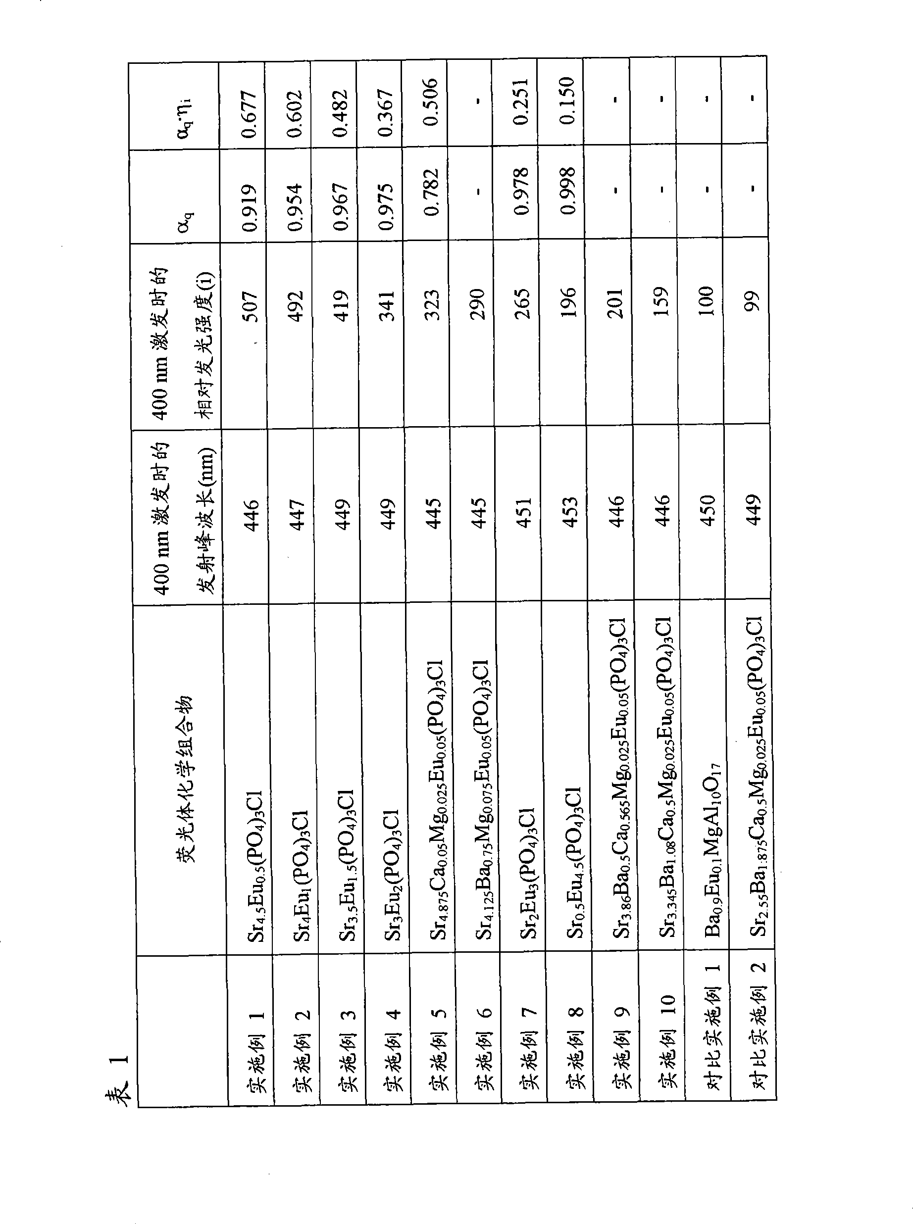
实施例11Example 11
除了改变SrHPO4,SrCl2,Eu2O3和(NH4)2HPO4的量,按照类似于实施例1的方式制得荧光体Sr(5-x)Eux(PO4)3Cl,其x落入范围0.05-5内。因此获得的荧光体暴露于254nm和400nm光下,测量各自的发光光谱。In addition to changing the amount of SrHPO 4 , SrCl 2 , Eu 2 O 3 and (NH 4 ) 2 HPO 4 , the phosphor Sr (5-x) Eu x (PO 4 ) 3 Cl was prepared in a manner similar to Example 1, Its x falls within the range 0.05-5. The phosphor thus obtained was exposed to light of 254 nm and 400 nm, and the respective emission spectra were measured.
图18中,示出了当各自在254nm和400nm激发时x和发光强度之间的关系。In Fig. 18, the relationship between x and luminous intensity when excited at 254 nm and 400 nm, respectively, is shown.
这里使用的相对发光强度(ii)意思是浓度x的发光强度,假定各自在254nm和400nm的最大发光强度为1。The relative luminous intensity (ii) used here means the luminous intensity of the concentration x, assuming that the maximum luminous intensities at 254 nm and 400 nm are 1, respectively.
由图18,发现在400nm和254nm激发的最大发光强度下,Eu浓度(摩尔数)x分别为0.5和≤0.05,前者大于后者。也发现在实施例1-4,7和8中,每个Eu浓度至少1.1倍于254nm激发时在最大发光强度的Eu浓度(≤0.05),并且落入0.5-9倍当400nm激发时在最大发光强度的Eu浓度(0.5)范围内。From Fig. 18, it is found that under the maximum luminous intensity excited at 400nm and 254nm, the Eu concentration (number of moles) x is 0.5 and ≤0.05 respectively, the former being greater than the latter. It was also found that in Examples 1-4, 7 and 8, each Eu concentration was at least 1.1 times the Eu concentration (≤0.05) at the maximum luminous intensity when excited at 254 nm, and fell within 0.5-9 times at the maximum when excited at 400 nm. The Eu concentration (0.5) range of the luminous intensity.
实施例12Example 12
称出二水合氯化钙(0.01382摩尔)和0.00028摩尔六水合氯化铕并溶解于20ml水中。向所得到的水溶液中根据磷酸的量为0.00846摩尔加入85%的磷酸。所得的混合物转移到磁性碟中得到30-40ml的总量。该溶液在搅拌下加热和干燥。收集干燥后的固体剩余物并在玛瑙研钵磨碎。部分粉碎产物转移到氧化铝坩锅,并在含有4%氢的氮气流下在1000℃烧结2小时,由此制得荧光体Ca4.9Eu0.1(PO4)3Cl。Calcium chloride dihydrate (0.01382 moles) and 0.00028 moles europium chloride hexahydrate were weighed out and dissolved in 20 ml of water. To the resulting aqueous solution was added 85% phosphoric acid based on the amount of phosphoric acid being 0.00846 moles. The resulting mixture was transferred to a magnetic dish to give a total volume of 30-40ml. The solution was heated and dried with stirring. The dried solid residue was collected and ground in an agate mortar. Part of the pulverized product was transferred to an alumina crucible, and sintered at 1000° C. for 2 hours under a nitrogen flow containing 4% hydrogen, thereby preparing phosphor Ca 4.9 Eu 0.1 (PO 4 ) 3 Cl.
在表2中,示出了当荧光体在400nm激发时的发射峰波长和相对发光强度(i),400nm为GaN发光二极管在紫外区域的主要波长。In Table 2, the emission peak wavelength and relative luminous intensity (i) are shown when the phosphor is excited at 400nm, which is the main wavelength of GaN light-emitting diodes in the ultraviolet region.
关于Ca(5-x)Eux(PO4)3Cl,由x和基于六方体系的晶格常数计算的晶胞体积,该六方体系的晶格常数为:

实施例13Example 13
称出二水合氯化钙(0.01325摩尔)和0.00055摩尔六水合氯化铕并溶解于20ml水中。向所得到的水溶液中根据磷酸的量为0.00828摩尔加入85%的磷酸。所得的混合物转移到磁性碟中得到30-40ml的总量。该溶液在搅拌下加热和干燥。干燥后的固体剩余物按类似于实施例12的方式处理,由此制得荧光体Ca4.8Eu0.2(PO4)3Cl。Calcium chloride dihydrate (0.01325 mol) and 0.00055 mol europium chloride hexahydrate were weighed out and dissolved in 20 ml of water. To the resulting aqueous solution was added 85% phosphoric acid based on the amount of phosphoric acid being 0.00828 moles. The resulting mixture was transferred to a magnetic dish to give a total volume of 30-40ml. The solution was heated and dried with stirring. The dried solid residue was treated in a manner similar to Example 12, thereby preparing phosphor Ca 4.8 Eu 0.2 (PO 4 ) 3 Cl.
在表2中,示出了当荧光体在400nm激发时的发射峰波长和相对发光强度(i),400nm为GaN发光二极管在紫外区域的主要波长。In Table 2, the emission peak wavelength and relative luminous intensity (i) are shown when the phosphor is excited at 400nm, which is the main wavelength of GaN light-emitting diodes in the ultraviolet region.
Eu-Eu平均距离为
实施例14Example 14
称出二水合氯化钙(0.0122摩尔)和0.00106摩尔六水合氯化铕并溶解于20ml水中。向所得到的水溶液中根据磷酸的量为0.00796摩尔加入85%的磷酸。所得的混合物转移到磁性碟中得到30-40ml的总量。滴加35%盐酸水溶液(50mL),接着在搅拌下加热和干燥。干燥后的固体剩余物按类似于实施例12的方式处理,由此制得荧光体Ca4.6Eu0.4(PO4)3Cl。Calcium chloride dihydrate (0.0122 mol) and 0.00106 mol europium chloride hexahydrate were weighed out and dissolved in 20 ml of water. To the resulting aqueous solution was added 85% phosphoric acid based on the amount of phosphoric acid being 0.00796 moles. The resulting mixture was transferred to a magnetic dish to give a total volume of 30-40ml. A 35% aqueous hydrochloric acid solution (50 mL) was added dropwise, followed by heating and drying with stirring. The dried solid residue was treated in a manner similar to that of Example 12, thereby preparing phosphor Ca 4.6 Eu 0.4 (PO 4 ) 3 Cl.
在表2中,示出了当荧光体在400nm激发时的发射峰波长和相对发光强度(i),400nm为GaN发光二极管在紫外区域的主要波长。In Table 2, the emission peak wavelength and relative luminous intensity (i) are shown when the phosphor is excited at 400nm, which is the main wavelength of GaN light-emitting diodes in the ultraviolet region.
Eu-Eu平均距离为
实施例15Example 15
称出二水合氯化钙(0.0117摩尔)和0.0013摩尔六水合氯化铕并溶解于20ml水中。向所得到的水溶液中根据磷酸的量为0.0078摩尔加入85%的磷酸。所得的混合物转移到磁性碟中得到30-40ml的总量。滴加35%盐酸水溶液(50mL),接着在搅拌下加热和干燥。干燥后的固体剩余物按类似于实施例12的方式处理,由此制得荧光体Ca4.5Eu0.5(PO4)3Cl。Calcium chloride dihydrate (0.0117 mol) and 0.0013 mol europium chloride hexahydrate were weighed out and dissolved in 20 ml of water. To the resulting aqueous solution was added 85% phosphoric acid based on the amount of phosphoric acid being 0.0078 mol. The resulting mixture was transferred to a magnetic dish to give a total volume of 30-40ml. A 35% aqueous hydrochloric acid solution (50 mL) was added dropwise, followed by heating and drying with stirring. The dried solid residue was treated in a manner similar to that of Example 12, thereby preparing phosphor Ca 4.5 Eu 0.5 (PO 4 ) 3 Cl.
在表2中,示出了当荧光体在400nm激发时的发射峰波长和相对发光强度(i),400nm为GaN发光二极管在紫外区域的主要波长。In Table 2, the emission peak wavelength and relative luminous intensity (i) are shown when the phosphor is excited at 400nm, which is the main wavelength of GaN light-emitting diodes in the ultraviolet region.
Eu-Eu平均距离为
实施例16Example 16
称出二水合氯化钙(0.01054摩尔)和0.00186摩尔六水合硝酸铕,并溶解于20ml水中。向所得到的水溶液中根据磷酸的量为0.00744摩尔加入85%的磷酸。所得的混合物转移到磁性碟中得到30-40ml的总量。滴加35%盐酸水溶液(100mL),接着在搅拌下加热和干燥。干燥后的固体剩余物按类似于实施例12的方式处理,由此制得荧光体Ca4.25Eu0.75(PO4)3Cl。发现所得到的荧光体的X-射线衍射图在晶体学上等同于Ca5(PO4)3Cl。Calcium chloride dihydrate (0.01054 moles) and 0.00186 moles of europium nitrate hexahydrate were weighed out and dissolved in 20 ml of water. To the resulting aqueous solution was added 85% phosphoric acid based on the amount of phosphoric acid being 0.00744 moles. The resulting mixture was transferred to a magnetic dish to give a total volume of 30-40ml. A 35% aqueous hydrochloric acid solution (100 mL) was added dropwise, followed by heating and drying with stirring. The dried solid residue was treated in a manner similar to that of Example 12, thereby preparing phosphor Ca 4.25 Eu 0.75 (PO 4 ) 3 Cl. The X-ray diffraction pattern of the resulting phosphor was found to be crystallographically identical to Ca 5 (PO 4 ) 3 Cl.
在表2中,示出了当荧光体在400nm激发时的发射峰波长和相对发光强度(i),400nm为GaN发光二极管在紫外区域的主要波长。In Table 2, the emission peak wavelength and relative luminous intensity (i) are shown when the phosphor is excited at 400nm, which is the main wavelength of GaN light-emitting diodes in the ultraviolet region.
Eu-Eu平均距离为
实施例17Example 17
称出二水合氯化钙(0.00948摩尔)和0.00237摩尔六水合硝酸铕,并溶解于20ml水中。向所得到的水溶液中根据磷酸的量为0.00711摩尔加入85%的磷酸。所得的混合物转移到磁性碟中得到30-40ml的总量。滴加35%盐酸水溶液(150mL),接着在搅拌下加热和干燥。干燥后的固体剩余物按类似于实施例12的方式处理,由此制得荧光体Ca4Eu1(PO4)3Cl。Calcium chloride dihydrate (0.00948 moles) and 0.00237 moles of europium nitrate hexahydrate were weighed out and dissolved in 20 ml of water. To the resulting aqueous solution was added 85% phosphoric acid based on the amount of phosphoric acid being 0.00711 mol. The resulting mixture was transferred to a magnetic dish to give a total volume of 30-40ml. A 35% aqueous hydrochloric acid solution (150 mL) was added dropwise, followed by heating and drying with stirring. The dried solid residue was treated in a manner similar to Example 12, thereby preparing phosphor Ca 4 Eu 1 (PO 4 ) 3 Cl.
在表2中,示出了当荧光体在400nm激发时的发射峰波长和相对发光强度(i),400nm为GaN发光二极管在紫外区域的主要波长。In Table 2, the emission peak wavelength and relative luminous intensity (i) are shown when the phosphor is excited at 400nm, which is the main wavelength of GaN light-emitting diodes in the ultraviolet region.
Eu-Eu平均距离为
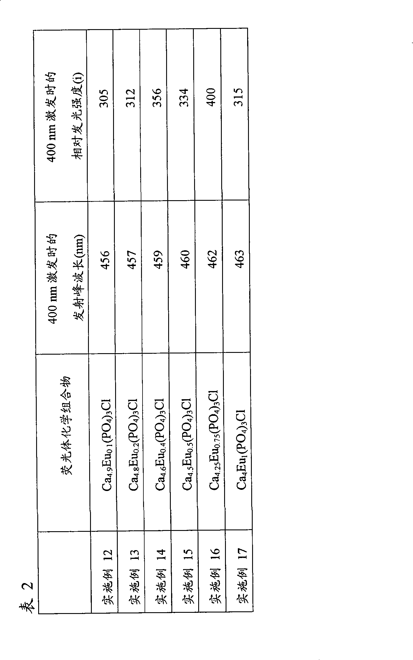
实施例18Example 18
称出二水合氯化钙(0.00948摩尔)和0.00237摩尔六水合硝酸铕并溶解于20ml水中。向所得到的水溶液中加入85%磷酸作为磷酸。除了改变氯化钙,硝酸铕,氯化铕,磷酸和盐酸的量,按类似于实施例12的方式,制得荧光体Ca(5-x)Eux(PO4)3Cl,其x落入范围0.01-1.25内。所得到的荧光体暴露于各自254nm和400nm光下测量其发光光谱。Calcium chloride dihydrate (0.00948 moles) and 0.00237 moles europium nitrate hexahydrate were weighed out and dissolved in 20 ml of water. To the resulting aqueous solution was added 85% phosphoric acid as phosphoric acid. Except changing the amounts of calcium chloride, europium nitrate, europium chloride, phosphoric acid and hydrochloric acid, phosphor Ca (5-x) Eu x (PO 4 ) 3 Cl was prepared in a manner similar to that of Example 12, where x fell Into the range of 0.01-1.25. The resulting phosphors were exposed to light of 254 nm and 400 nm respectively to measure their emission spectra.
当该荧光体在254nm和400nm各自激发时,x和发光强度之间的关系显示于中图19.When this phosphor is excited at 254 nm and 400 nm respectively, the relationship between x and luminous intensity is shown in Figure 19.
这里使用的相对发光强度(ii)意思是浓度x的发光强度,假定各自在254nm和400nm的最大发光强度为1。The relative luminous intensity (ii) used here means the luminous intensity of the concentration x, assuming that the maximum luminous intensities at 254 nm and 400 nm are 1, respectively.
由图19,发现在400nm和254nm激发的最大发光强度下,Eu浓度(摩尔数)x分别为0.75和0.05,前者大于后者。也发现在实施例14-17中,每个Eu浓度至少1.1倍于254nm激发时在最大发光强度的Eu浓度(≤0.05),并且落入0.5-9倍当400nm激发时在最大发光强度的Eu浓度(0.5)范围内。From Fig. 19, it is found that under the maximum luminous intensity excited by 400nm and 254nm, the Eu concentration (number of moles) x is 0.75 and 0.05 respectively, the former is greater than the latter. It was also found that in Examples 14-17, each Eu concentration was at least 1.1 times the Eu concentration (≤0.05) at the maximum luminescence intensity when excited at 254 nm, and fell within 0.5-9 times the Eu concentration at the maximum luminescence intensity when excited at 400 nm. Concentration (0.5) range.
实施例19Example 19
在由氧化铝制成和含有珠子的湿-型球磨机中,用纯水粉碎和混合0.00798摩尔BaCO3,碱式碳酸镁(0.0114摩尔,按Mg),0.0570摩尔γ-Al2O3,和0.00171摩尔Eu2O3。干燥后,所得的混合物穿过尼龙网,在含有4%氢的氮气流下,该粉碎的混合物通过加热到1600℃在氧化铝坩锅中烧结2小时。该烧结体接着用水洗涤,干燥和分类,由此制得蓝光发射荧光体Ba0.7Eu0.3MgAl10O17。In a wet-type ball mill made of alumina and containing beads, 0.00798 moles of BaCO 3 , basic magnesium carbonate (0.0114 moles as Mg), 0.0570 moles of γ-Al 2 O 3 , and 0.00171 moles of Eu 2 O 3 . After drying, the resulting mixture was passed through a nylon mesh, and the pulverized mixture was sintered in an alumina crucible by heating to 1600° C. for 2 hours under a nitrogen flow containing 4% hydrogen. The sintered body was then washed with water, dried and classified, thereby producing a blue light-emitting phosphor Ba 0.7 Eu 0.3 MgAl 10 O 17 .
所得到的荧光体在400nm和254nm激发,400nm为GaN光发射二极管在紫外区域的主要波长,254nm为用作普通荧光灯的低压汞灯的主要波长,由此测量发光光谱。在表3中,示出了当荧光体在400nm激发时的发射峰波长,和当荧光体各自在400nm和254nm激发时的相对发光强度(i)。The obtained phosphor was excited at 400nm, which is the main wavelength of GaN light-emitting diodes in the ultraviolet region, and 254nm, which is the main wavelength of a low-pressure mercury lamp used as a general fluorescent lamp, and 254nm, whereby the emission spectrum was measured. In Table 3, the emission peak wavelengths when the phosphors were excited at 400 nm, and the relative luminescence intensities (i) when the phosphors were respectively excited at 400 nm and 254 nm are shown.
关于Ba(1-x)EuxMgAl10O17,由x和基于六方体系的晶格常数计算的晶胞体积,确定每结晶基体(crystalline matrix)体积的Eu数目,该六方体系的晶格常数为:和

实施例20Example 20
除了使用0.00570摩尔BaCO3,碱式碳酸镁(0.0114摩尔,按Mg),0.0570摩尔γ-Al2O3,和0.00285摩尔Eu2O3作为原材料,按类似于实施例19的方式,制得荧光体Ba0.5Eu0.5MgAl10O17。 In a similar manner to Example 19 , a fluorescent Bulk Ba 0.5 Eu 0.5 MgAl 10 O 17 .
所得到的荧光体的X-射线衍射图显示于图21中。由该图,发现图21的峰的式样在晶体学上等同于图20的BaMgAl10O17。The X-ray diffraction pattern of the obtained phosphor is shown in FIG. 21 . From this figure, it was found that the pattern of the peaks in FIG. 21 is crystallographically equivalent to BaMgAl 10 O 17 in FIG. 20 .
所得到的荧光体在400nm和254nm激发,400nm为GaN光发射二极管在紫外区域的主要波长,254nm为用作普通荧光灯的低压汞灯的主要波长,由此测量发光光谱。在表3中,示出了当荧光体在400nm激发时的发射峰波长,和当荧光体各自在400nm和254nm激发时的相对发光强度(i)。The obtained phosphor was excited at 400nm, which is the main wavelength of GaN light-emitting diodes in the ultraviolet region, and 254nm, which is the main wavelength of a low-pressure mercury lamp used as a general fluorescent lamp, and 254nm, whereby the emission spectrum was measured. In Table 3, the emission peak wavelengths when the phosphors were excited at 400 nm, and the relative luminescence intensities (i) when the phosphors were respectively excited at 400 nm and 254 nm are shown.
Eu-Eu平均距离为
实施例21Example 21
除了使用0.00912摩尔BaCO3,碱式碳酸镁(0.0114摩尔,按Mg),0.0570摩尔γ-Al2O3,和0.00114摩尔Eu2O3作为原材料,按类似于实施例19的方式,制得荧光体Ba0.8Eu0.2MgAl10O17。 In a similar manner to Example 19 , a fluorescent Bulk Ba 0.8 Eu 0.2 MgAl 10 O 17 .
所得到的荧光体在400nm和254nm激发,400nm为GaN光发射二极管在紫外区域的主要波长,254nm为用作普通荧光灯的低压汞灯的主要波长,由此测量发光光谱。在表3中,示出了当荧光体在400nm激发时的发射峰波长,和当荧光体各自在400nm和254nm激发时的相对发光强度(i)。The obtained phosphor was excited at 400nm, which is the main wavelength of GaN light-emitting diodes in the ultraviolet region, and 254nm, which is the main wavelength of a low-pressure mercury lamp used as a general fluorescent lamp, and 254nm, whereby the emission spectrum was measured. In Table 3, the emission peak wavelengths when the phosphors were excited at 400 nm, and the relative luminescence intensities (i) when the phosphors were respectively excited at 400 nm and 254 nm are shown.
Eu-Eu平均距离为
实施例22Example 22
除了使用0.00502摩尔BaCO3,0.00410摩尔CaCO3,碱式碳酸镁(0.0114摩尔,按Mg),0.0570摩尔γ-Al2O3,和0.00114摩尔Eu2O3作为原材料,按类似于实施例19的方式,制得荧光体Ba0.44Ca0.36Eu0.2MgAl10O17。Except using 0.00502 moles of BaCO 3 , 0.00410 moles of CaCO 3 , basic magnesium carbonate (0.0114 moles as Mg), 0.0570 moles of γ-Al 2 O 3 , and 0.00114 moles of Eu 2 O 3 as raw materials, similar to Example 19 way, the phosphor Ba 0.44 Ca 0.36 Eu 0.2 MgAl 10 O 17 was prepared.
所得到的荧光体在400nm激发,400nm为GaN光发射二极管在紫外区域的主要波长,由此测量发光光谱。在表3中,示出了当荧光体在400nm激发时的发射峰波长和相对发光强度(i)。The obtained phosphor was excited at 400nm, which is the main wavelength of the GaN light-emitting diode in the ultraviolet region, thereby measuring the emission spectrum. In Table 3, the emission peak wavelength and relative luminescence intensity (i) when the phosphor is excited at 400 nm are shown.
Eu-Eu平均距离为
实施例23Example 23
除了使用0.00502摩尔BaCO3,0.00410摩尔SrCO3,碱式碳酸镁(0.0114摩尔,按Mg),0.0570摩尔γ-Al2O3,0.00114摩尔Eu2O3作为原材料,按类似于实施例19的方式,制得荧光体Ba0.44Sr0.36Eu0.2MgAl10O17。Except using 0.00502 moles of BaCO 3 , 0.00410 moles of SrCO 3 , basic magnesium carbonate (0.0114 moles as Mg), 0.0570 moles of γ-Al 2 O 3 , 0.00114 moles of Eu 2 O 3 as raw materials, in a manner similar to Example 19 , to prepare phosphor Ba 0.44 Sr 0.36 Eu 0.2 MgAl 10 O 17 .
所得到的荧光体在400nm激发,400nm为GaN光发射二极管在紫外区域的主要波长,由此测量发光光谱。在表3中,示出了当荧光体在400nm激发时的发射峰波长和相对发光强度(i)。The obtained phosphor was excited at 400nm, which is the main wavelength of the GaN light-emitting diode in the ultraviolet region, thereby measuring the emission spectrum. In Table 3, the emission peak wavelength and relative luminescence intensity (i) when the phosphor is excited at 400 nm are shown.
Eu-Eu平均距离为
对比实施例3Comparative Example 3
除了使用0.0103摩尔BaCO3,碱式碳酸镁(0.0114摩尔,按Mg),0.0570摩尔γ-Al2O3,和0.00057摩尔Eu2O3作为原材料,按类似于实施例19的方式,制得荧光体Ba0.9Eu0.1MgAl10O17,其具有类似于商购的蓝光发射荧光体的组合物。 In a similar manner to Example 19 , a fluorescent body Ba 0.9 Eu 0.1 MgAl 10 O 17 , which has a composition similar to commercially available blue light-emitting phosphors.
所得到的荧光体在400nm和254nm激发,400nm为GaN光发射二极管在紫外区域的主要波长,254nm为用作普通荧光灯的低压汞灯的主要波长,由此测量发光光谱。在表3中,示出了当荧光体在400nm激发时的发射峰波长,和当荧光体各自在400nm和254nm激发时的相对发光强度(i)。由表中发现当它们在400nm激发时,实施例19的荧光体的发光强度1.9倍于对比实施例获得的荧光体。The obtained phosphor was excited at 400nm, which is the main wavelength of GaN light-emitting diodes in the ultraviolet region, and 254nm, which is the main wavelength of a low-pressure mercury lamp used as a general fluorescent lamp, and 254nm, whereby the emission spectrum was measured. In Table 3, the emission peak wavelengths when the phosphors were excited at 400 nm, and the relative luminescence intensities (i) when the phosphors were respectively excited at 400 nm and 254 nm are shown. It is found from the table that the luminescent intensity of the phosphors of Example 19 is 1.9 times that of the phosphors obtained in Comparative Example when they are excited at 400 nm.
Eu-Eu平均距离为
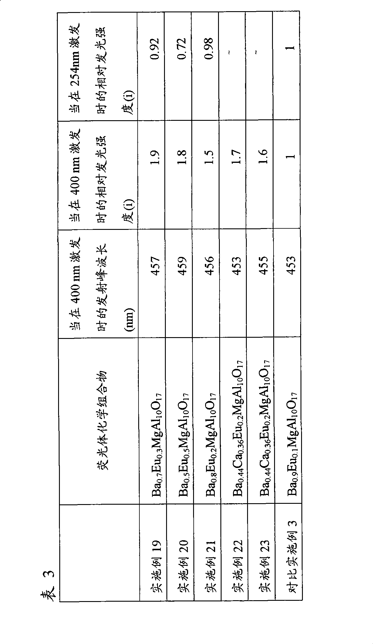
实施例24Example 24
除了改变BaCO3,碱式碳酸镁,γ-Al2O3和Eu2O3的量,按类似于实施例19的方式制得荧光体Ba(1-x)EuxMgAl10O17,其x落入0-1内。所得到的荧光体暴露于254nm和400nm光下测量发光光谱。Except changing the amounts of BaCO 3 , basic magnesium carbonate, γ-Al 2 O 3 and Eu 2 O 3 , phosphor Ba (1-x) Eu x MgAl 10 O 17 was prepared in a manner similar to Example 19, which x falls within 0-1. The obtained phosphor was exposed to light of 254 nm and 400 nm to measure the emission spectrum.
图22中,示出了当荧光体各自在254nm和400nm激发时的x和发光强度之间的关系。In FIG. 22 , the relationship between x and luminous intensity when the phosphors are each excited at 254 nm and 400 nm is shown.
在该体系中,Eu可以被Ba位点取代使得实际Eu取代数目对所有Eu被取代位点的比率为x。这里相对发光强度(ii)的意思是假定在254nm和400nm的最大发光强度各自为1时,在浓度x的发光强度。In this system, Eu can be substituted by Ba sites such that the ratio of the actual number of Eu substitutions to all Eu substituted sites is x. The relative luminous intensity (ii) here means the luminous intensity at the concentration x assuming that the maximum luminous intensities at 254 nm and 400 nm are each 1.
由图22发现发现在400nm和254nm激发的最大发光强度下,Eu浓度(摩尔数)x分别为0.3和0.1,前者大于后者。也发现在实施例19-23中,每个Eu浓度至少1.1倍于254nm激发时在最大发光强度的Eu浓度(0.1),并且落入0.5-9倍当400nm激发时在最大发光强度的Eu浓度(0.3)范围内。It is found from FIG. 22 that under the maximum luminous intensity excited by 400nm and 254nm, the Eu concentration (number of moles) x is 0.3 and 0.1 respectively, the former being greater than the latter. It was also found that in Examples 19-23, each Eu concentration was at least 1.1 times the Eu concentration (0.1) at the maximum luminescence intensity when excited at 254 nm, and fell within 0.5-9 times the Eu concentration at the maximum luminescence intensity when excited at 400 nm (0.3) range.
当它们各自在254nm和400nm激发时,每个荧光体的Eu-Eu平均距离和发光强度之间的关系显示于图23中。此处相对发光强度(ii)的意思是指假定在254nm和400nm激发的最大发光强度分别为1时,在Eu-Eu平均距离的发光强度。当在400nm激发的发光强度达到最大时,Eu-Eu平均距离为当在254nm激发的发光强度达到最大时,Eu-Eu平均距离为暗示了长于当在400nm激发的发光强度达到最大时的Eu-Eu平均距离。The relationship between the Eu-Eu average distance and the luminescence intensity of each phosphor is shown in FIG. 23 when they were respectively excited at 254 nm and 400 nm. The relative luminous intensity (ii) here means the luminous intensity at the Eu-Eu average distance assuming that the maximum luminous intensities excited at 254 nm and 400 nm are 1, respectively. When the luminous intensity excited at 400nm reaches the maximum, the Eu-Eu average distance is When the luminous intensity excited at 254nm reaches the maximum, the Eu-Eu average distance is Longer than the Eu-Eu average distance when the luminescence intensity excited at 400 nm reaches a maximum is implied.
实施例25Example 25
在由氧化铝制成和含有珠子的湿-型球磨机中,用纯水粉碎和混合0.0553摩尔BaCO3,0.0186摩尔(按Mg)碱式碳酸镁,0.0372摩尔SiO2,和0.00018摩尔Eu2O3。干燥后,所得的混合物穿过尼龙网,在含有4%氢的氮气流下,该粉碎的混合物通过加热到1200℃在氧化铝坩锅中烧结2小时。该烧结体接着用水洗涤,干燥和分类,由此制得蓝光发射荧光体。In a wet-type ball mill made of alumina and containing beads, pulverize and mix 0.0553 moles of BaCO 3 , 0.0186 moles (as Mg) of basic magnesium carbonate, 0.0372 moles of SiO 2 , and 0.00018 moles of Eu 2 O 3 . After drying, the resulting mixture was passed through a nylon mesh, and the pulverized mixture was sintered in an alumina crucible by heating to 1200° C. for 2 hours under a nitrogen flow containing 4% hydrogen. The sintered body was then washed with water, dried and classified, whereby a blue light-emitting phosphor was produced.
所得到的荧光体的X-射线衍射图Ba2.98Eu0.02MgSi2O8显示于图27中。表明图27的峰的式样在晶体学上等同于图24的Ba3MgSi2O8。The X-ray diffraction pattern Ba 2.98 Eu 0.02 MgSi 2 O 8 of the obtained phosphor is shown in FIG. 27 . It is shown that the pattern of the peaks of FIG. 27 is crystallographically equivalent to Ba 3 MgSi 2 O 8 of FIG. 24 .
在400nm激发所得荧光体的发光光谱显示于图28中,400nm为GaN发光二极管在紫外区域主要波长。发射峰波长和相对发光强度(i)显示于表4中。The luminescent spectrum of the obtained phosphor excited at 400nm is shown in FIG. 28, and 400nm is the main wavelength of the GaN light-emitting diode in the ultraviolet region. The emission peak wavelengths and relative luminescence intensities (i) are shown in Table 4.
实施例26Example 26
除了使用0.0553摩尔SrCO3代替BaCO3,按类似于实施例25的方式制得荧光体。A phosphor was prepared in a manner similar to Example 25, except that 0.0553 mol of SrCO 3 was used instead of BaCO 3 .
所得到的荧光体的X-射线衍射图Sr2.98Eu0.02MgSi2O8显示于图29中。发现图29的峰的式样在晶体学上等同于图25的Sr3MgSi2O8。当所得荧光体在400nm激发时的发射峰波长和相对发光强度(i)显示于表4中,400nm为GaN发光二极管在紫外区域主要波长。The X-ray diffraction pattern Sr 2.98 Eu 0.02 MgSi 2 O 8 of the obtained phosphor is shown in FIG. 29 . The pattern of the peaks of FIG. 29 was found to be crystallographically equivalent to Sr 3 MgSi 2 O 8 of FIG. 25 . The emission peak wavelength and relative luminous intensity (i) when the obtained phosphor is excited at 400nm are shown in Table 4, and 400nm is the main wavelength of the GaN light-emitting diode in the ultraviolet region.
实施例27Example 27
除了使用0.0442摩尔BaCO3,0.0084摩尔CaCO3和0.0028摩尔MnCO3代替BaCO3,按类似于实施例25的方式制得荧光体Ba2.38Eu0.02Ca0.45Mn0.15MgSi2O8。Phosphor Ba 2.38 Eu 0.02 Ca 0.45 Mn 0.15 MgSi 2 O 8 was prepared in a manner similar to Example 25 except that 0.0442 mol of BaCO 3 , 0.0084 mol of CaCO 3 and 0.0028 mol of MnCO 3 were used instead of BaCO 3 .
当荧光体在400nm激发时的发射峰波长和相对发光强度(i)显示于表4中,400nm为GaN发光二极管在紫外区域主要波长。The emission peak wavelength and relative luminous intensity (i) when the phosphor is excited at 400nm are shown in Table 4, and 400nm is the main wavelength of the GaN light-emitting diode in the ultraviolet region.
实施例28Example 28
除了使用0.0186摩尔(按Zn)碱式碳酸锌替代碱式碳酸镁,按类似于实施例25的方式制得荧光体Ba2.98Eu0.02ZnSi2O8。Phosphor Ba 2.98 Eu 0.02 ZnSi 2 O 8 was prepared in a similar manner to Example 25, except that 0.0186 mol (as Zn) of basic zinc carbonate was used instead of basic magnesium carbonate.
当荧光体在400nm激发时的发射峰波长和相对发光强度(i)显示于表4中,400nm为GaN发光二极管在紫外区域主要波长。The emission peak wavelength and relative luminous intensity (i) when the phosphor is excited at 400nm are shown in Table 4, and 400nm is the main wavelength of the GaN light-emitting diode in the ultraviolet region.
实施例29Example 29
除了分别改变BaCO3和Eu2O3量为0.0556摩尔和0.000074摩尔,按类似于实施例25的方式制得荧光体Ba2.992Eu0.008MgSi2O8。Phosphor Ba 2.992 Eu 0.008 MgSi 2 O 8 was prepared in a manner similar to Example 25, except that the amounts of BaCO 3 and Eu 2 O 3 were changed to 0.0556 mol and 0.000074 mol, respectively.
当荧光体在400nm激发时的发射峰波长和相对发光强度(i)显示于表4中,400nm为GaN发光二极管在紫外区域主要波长。The emission peak wavelength and relative luminous intensity (i) when the phosphor is excited at 400nm are shown in Table 4, and 400nm is the main wavelength of the GaN light-emitting diode in the ultraviolet region.
实施例30Example 30
除了改变烧结温度为1300℃,按类似于实施例25的方式制得荧光体Ba2.98Eu0.02MgSi2O8。Phosphor Ba 2.98 Eu 0.02 MgSi 2 O 8 was prepared in a manner similar to Example 25 except that the sintering temperature was changed to 1300°C.
当荧光体在400nm激发时的发射峰波长和相对发光强度(i)显示于表4中,400nm为GaN发光二极管在紫外区域主要波长。The emission peak wavelength and relative luminous intensity (i) when the phosphor is excited at 400nm are shown in Table 4, and 400nm is the main wavelength of the GaN light-emitting diode in the ultraviolet region.
实施例31Example 31
除了分别改变BaCO3和Eu2O3量为0.0549摩尔和0.00047摩尔,按类似于实施例25的方式制得荧光体Ba2.95Eu0.05MgSi2O8。Phosphor Ba 2.95 Eu 0.05 MgSi 2 O 8 was prepared in a manner similar to Example 25, except that the amounts of BaCO 3 and Eu 2 O 3 were changed to 0.0549 moles and 0.00047 moles, respectively.
当荧光体在400nm激发时的发射峰波长和相对发光强度(i)显示于表4中,400nm为GaN发光二极管在紫外区域主要波长。The emission peak wavelength and relative luminous intensity (i) when the phosphor is excited at 400nm are shown in Table 4, and 400nm is the main wavelength of the GaN light-emitting diode in the ultraviolet region.
实施例32Example 32
除了分别改变BaCO3和Eu2O3量为0.0539摩尔和0.00093摩尔,按类似于实施例25的方式制得荧光体Ba2.9Eu0.1MgSi2O8。Phosphor Ba 2.9 Eu 0.1 MgSi 2 O 8 was prepared in a similar manner to Example 25, except that the amounts of BaCO 3 and Eu 2 O 3 were changed to 0.0539 mol and 0.00093 mol, respectively.
当荧光体在400nm激发时的发射峰波长和相对发光强度(i)显示于表4中,400nm为GaN发光二极管在紫外区域主要波长。The emission peak wavelength and relative luminous intensity (i) when the phosphor is excited at 400nm are shown in Table 4, and 400nm is the main wavelength of the GaN light-emitting diode in the ultraviolet region.
实施例33Example 33
除了分别改变BaCO3和Eu2O3量为0.0530摩尔和0.00140摩尔,按类似于实施例25的方式制得荧光体Ba2.85Eu0.15MgSi2O8。Phosphor Ba 2.85 Eu 0.15 MgSi 2 O 8 was prepared in a manner similar to Example 25, except that the amounts of BaCO 3 and Eu 2 O 3 were changed to 0.0530 mol and 0.00140 mol, respectively.
当荧光体在400nm激发时的发射峰波长和相对发光强度(i)显示于表4中,400nm为GaN发光二极管在紫外区域主要波长。The emission peak wavelength and relative luminous intensity (i) when the phosphor is excited at 400nm are shown in Table 4, and 400nm is the main wavelength of the GaN light-emitting diode in the ultraviolet region.
实施例34Example 34
除了分别改变BaCO3和Eu2O3量为0.0521摩尔和0.00186摩尔,按类似于实施例25的方式制得荧光体Ba2.8Eu0.2MgSi2O8。Phosphor Ba 2.8 Eu 0.2 MgSi 2 O 8 was prepared in a manner similar to Example 25, except that the amounts of BaCO 3 and Eu 2 O 3 were changed to 0.0521 mol and 0.00186 mol, respectively.
当荧光体在400nm激发时的发射峰波长和相对发光强度(i)显示于表4中,400nm为GaN发光二极管在紫外区域主要波长。The emission peak wavelength and relative luminous intensity (i) when the phosphor is excited at 400nm are shown in Table 4, and 400nm is the main wavelength of the GaN light-emitting diode in the ultraviolet region.
实施例35Example 35
除了分别改变BaCO3和Eu2O3量为0.0502摩尔和0.00279摩尔,按类似于实施例25的方式制得荧光体Ba2.7Eu0.3MgSi2O8。Phosphor Ba 2.7 Eu 0.3 MgSi 2 O 8 was prepared in a manner similar to Example 25, except that the amounts of BaCO 3 and Eu 2 O 3 were changed to 0.0502 mol and 0.00279 mol, respectively.
当荧光体在400nm激发时的发射峰波长和相对发光强度(i)显示于表4中,400nm为GaN发光二极管在紫外区域主要波长。The emission peak wavelength and relative luminous intensity (i) when the phosphor is excited at 400nm are shown in Table 4, and 400nm is the main wavelength of the GaN light-emitting diode in the ultraviolet region.
对比实施例4Comparative Example 4
在由氧化铝制成和含有珠子的湿-型球磨机中,用纯水粉碎和混合0.0103摩尔BaCO3,0.0103摩尔(按Mg)的碱式碳酸镁,0.0570摩尔γ-Al2O3,和0.00057摩尔Eu2O3。干燥后,所得的混合物穿过尼龙网,在含有4%氢的氮气流下,该粉碎的混合物通过加热到1500℃在氧化铝坩锅中烧结2小时。该烧结体接着用水洗涤,干燥和分类,由此制得蓝光发射荧光体(Ba0.9Eu0.1MgAl10O17)。In a wet-type ball mill made of alumina and containing beads, 0.0103 moles of BaCO 3 , 0.0103 moles of basic magnesium carbonate (by Mg), 0.0570 moles of γ-Al 2 O 3 , and 0.00057 moles of Eu 2 O 3 . After drying, the resulting mixture was passed through a nylon mesh, and the pulverized mixture was sintered in an alumina crucible by heating to 1500° C. for 2 hours under a nitrogen flow containing 4% hydrogen. The sintered body was then washed with water, dried and classified, whereby a blue light-emitting phosphor (Ba 0.9 Eu 0.1 MgAl 10 O 17 ) was produced.
所得到的荧光体在400nm激发的发光光谱显示于图28中,400nm为GaN光发射二极管在紫外区域的主要波长,并比较了实施例25和对比实施例4获得的蓝光发射荧光体的性能。发射峰波长和相对发光强度(i)显示于表4中。发现当每个荧光体在400nm激发时,实施例25获得的荧光体的发光强度2.8倍于对比实施例4获得的荧光体。The luminescent spectrum of the obtained phosphor excited at 400nm is shown in FIG. 28, 400nm is the main wavelength of the GaN light-emitting diode in the ultraviolet region, and the performance of the blue light-emitting phosphor obtained in Example 25 and Comparative Example 4 was compared. The emission peak wavelengths and relative luminescence intensities (i) are shown in Table 4. It was found that the luminescent intensity of the phosphor obtained in Example 25 was 2.8 times that of the phosphor obtained in Comparative Example 4 when each phosphor was excited at 400 nm.
对比实施例5Comparative Example 5
在由氧化铝制成和含有珠子的湿-型球磨机中,用纯水粉碎和混合0.0238摩尔Y2O3,0.0400摩尔γ-Al2O3,和0.00048摩尔CeO2。干燥后,所得的混合物穿过尼龙网,在含有4%氢的氮气流下,该粉碎的混合物通过加热到1500℃在氧化铝坩锅中烧结2小时。该烧结体接着用水洗涤,干燥和分类,由此制得黄光发射荧光体(Y2.98Ce0.03Al5O12)。In a wet-type ball mill made of alumina and containing beads, 0.0238 mol of Y 2 O 3 , 0.0400 mol of γ-Al 2 O 3 , and 0.00048 mol of CeO 2 were pulverized and mixed with pure water. After drying, the resulting mixture was passed through a nylon mesh, and the pulverized mixture was sintered in an alumina crucible by heating to 1500° C. for 2 hours under a nitrogen flow containing 4% hydrogen. The sintered body was then washed with water, dried and classified, whereby a yellow light-emitting phosphor (Y 2.98 Ce 0.03 Al 5 O 12 ) was produced.
荧光体的发射峰波长和相对发光强度(i)显示于表4中。发现当每个荧光体在400nm激发时,实施例25获得的荧光体的发光强度250倍于对比实施例5获得的荧光体。The emission peak wavelengths and relative luminescence intensities (i) of the phosphors are shown in Table 4. It was found that the luminescent intensity of the phosphor obtained in Example 25 was 250 times that of the phosphor obtained in Comparative Example 5 when each phosphor was excited at 400 nm.
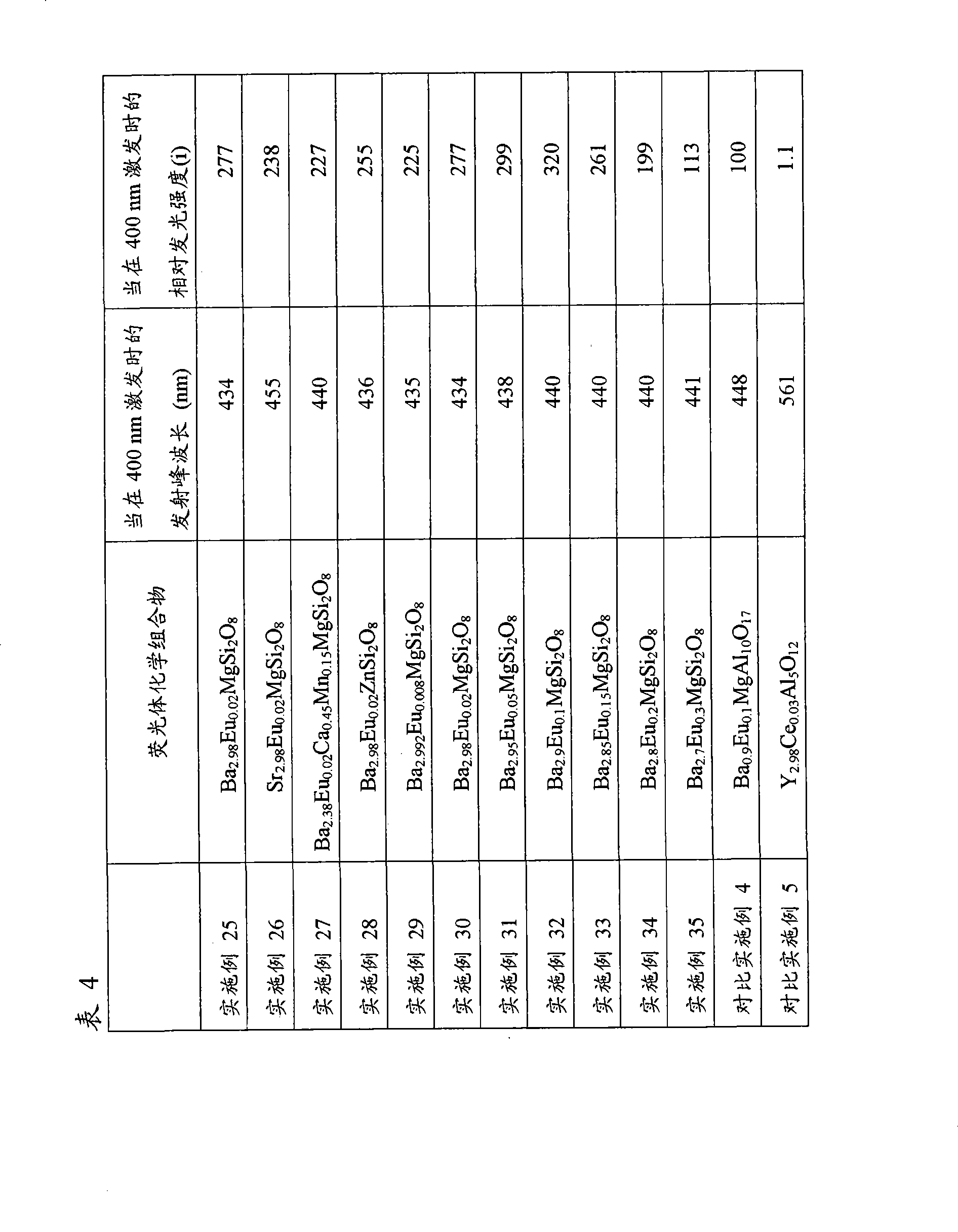
实施例36Example 36
除了改变BaCO3和Eu2O3的量,按类似于实施例25的方式制得荧光体Ba(1-x)EuxMgSi2O8,其x落入0.003-2内。所得到的荧光体暴露于254nm和400nm光下测量发光光谱。Except changing the amounts of BaCO 3 and Eu 2 O 3 , a phosphor Ba (1-x) Eu x MgSi 2 O 8 was prepared in a similar manner to Example 25, where x fell within 0.003-2. The obtained phosphor was exposed to light of 254 nm and 400 nm to measure the emission spectrum.
图30中,示出了当荧光体各自在254nm和400nm激发时的x和发光强度之间的关系。In FIG. 30 , the relationship between x and luminous intensity when the phosphors are each excited at 254 nm and 400 nm is shown.
此处相对发光强度(ii)的意思是假定在254nm和400nm的最大发光强度各自为1时,在浓度x的发光强度。The relative luminous intensity (ii) here means the luminous intensity at the concentration x assuming that the maximum luminous intensities at 254 nm and 400 nm are each 1.
由图30发现发现在400nm和254nm激发的最大发光强度下,Eu浓度(摩尔数)x分别为0.1和0.02,前者大于后者。也发现在实施例19-23中,每个Eu浓度至少1.1倍于254nm激发时在最大发光强度的Eu浓度(0.02),并且落入0.5-9倍当400nm激发时在最大发光强度的Eu浓度(0.5)范围内。It is found from Fig. 30 that under the maximum luminous intensity excited by 400nm and 254nm, the Eu concentration (mole number) x is 0.1 and 0.02 respectively, and the former is greater than the latter. It was also found that in Examples 19-23, each Eu concentration was at least 1.1 times the Eu concentration (0.02) at the maximum luminescence intensity when excited at 254 nm, and fell within 0.5-9 times the Eu concentration at the maximum luminescence intensity when excited at 400 nm (0.5) range.
实施例37Example 37
在由氧化铝制成和含有珠子的湿-型球磨机中,用纯水粉碎和混合0.06摩尔CaHPO4,0.0255摩尔CaCO3,0.06摩尔MgHPO4,0.0255摩尔MgCO3和0.0045摩尔Eu2O3。干燥后,所得的混合物穿过尼龙网,在含有4%氢的氮气流下,该粉碎的混合物通过加热到1100℃在氧化铝坩锅中烧结2小时。该烧结体接着用水洗涤,干燥和分类,由此制得蓝光发射荧光体Eu0.15Ca1.425Mg1.425(PO4)2。In a wet-type ball mill made of alumina and containing beads, 0.06 mol of CaHPO 4 , 0.0255 mol of CaCO 3 , 0.06 mol of MgHPO 4 , 0.0255 mol of MgCO 3 and 0.0045 mol of Eu 2 O 3 were pulverized and mixed with pure water. After drying, the resulting mixture was passed through a nylon mesh, and the pulverized mixture was sintered in an alumina crucible by heating to 1100° C. for 2 hours under a nitrogen flow containing 4% hydrogen. The sintered body was then washed with water, dried and classified, thereby producing a blue light-emitting phosphor Eu 0.15 Ca 1.425 Mg 1.425 (PO 4 ) 2 .
所得到的荧光体的X-射线衍射图显示于图32中。表明图32的峰的式样在晶体学上等同于图31的Ca3Mg3(PO4)4。The X-ray diffraction pattern of the obtained phosphor is shown in FIG. 32 . It is shown that the pattern of the peaks of FIG. 32 is crystallographically equivalent to Ca 3 Mg 3 (PO 4 ) 4 of FIG. 31 .
所得到的荧光体在400nm激发的发光光谱显示于图33中,400nm为GaN发光二极管在紫外区域主要波长。在表5中,示出了波长,相对积分强度,半值宽度,和发射峰相对发光强度(i),以及当254nm激发时相对发光强度(i)。The luminescence spectrum of the obtained phosphor excited at 400nm is shown in FIG. 33, and 400nm is the main wavelength of GaN light-emitting diodes in the ultraviolet region. In Table 5, wavelength, relative integrated intensity, half-value width, and emission peak relative luminous intensity (i), and relative luminous intensity (i) when excited at 254 nm are shown.
关于EuxCa(1.5-0.5x)Mg(1.5-0.5x)(PO4)2,由x和基于六方体系的晶格常数计算的晶胞体积,该六方体系的晶格常数为:

实施例38Example 38
除了使用0.06摩尔CaHPO4,0.0282摩尔CaCO3,0.06摩尔MgHPO4,0.0282摩尔MgCO3和0.0018摩尔Eu2O3代替作为原材料,按类似于实施例37的方式制得荧光体Eu0.06Ca1.47Mg1.47(PO4)2。Phosphor Eu 0.06 Ca 1.47 Mg 1.47 was prepared in a manner similar to Example 37, except that 0.06 mol CaHPO 4 , 0.0282 mol CaCO 3 , 0.06 mol MgHPO 4 , 0.0282 mol MgCO 3 and 0.0018 mol Eu 2 O 3 were used instead as raw materials. (PO 4 ) 2 .
所得到的荧光体的X-射线衍射图显示于图34中。表明图34的峰的式样在晶体学上等同于图31的Ca3Mg3(PO4)4。The X-ray diffraction pattern of the obtained phosphor is shown in FIG. 34 . It is shown that the pattern of the peaks of FIG. 34 is crystallographically equivalent to Ca 3 Mg 3 (PO 4 ) 4 of FIG. 31 .
所得到的荧光体在400nm激发,即,GaN发光二极管在紫外区域的主要波长以测量其发光光谱。在表5中,示出了波长,相对积分强度,半值宽度,和其发射峰的相对发光强度(i),和当254nm激发时的相对发光强度(i)。The resulting phosphor was excited at 400 nm, ie, the main wavelength of the GaN light-emitting diode in the ultraviolet region, to measure its emission spectrum. In Table 5, wavelength, relative integrated intensity, half-value width, and relative luminous intensity (i) of its emission peak, and relative luminous intensity (i) when excited at 254 nm are shown.
Eu-Eu平均距离为
实施例39Example 39
除了使用0.06摩尔CaHPO4,0.0291摩尔CaCO3,0.06摩尔MgHPO4,0.0291摩尔MgCO3和0.0009摩尔Eu2O3代替作为原材料,按类似于实施例37的方式制得荧光体Eu0.03Ca1.485Mg1.485(PO4)2。 Phosphor Eu 0.03 Ca 1.485 Mg 1.485 _ _ (PO 4 ) 2 .
所得到的荧光体在400nm激发,即,GaN发光二极管在紫外区域的主要波长以测量其发光光谱。在表5中,示出了波长,相对积分强度,半值宽度,和其发射峰的相对发光强度(i),和当254nm激发时的相对发光强度(i)。The resulting phosphor was excited at 400 nm, ie, the main wavelength of the GaN light-emitting diode in the ultraviolet region, to measure its emission spectrum. In Table 5, wavelength, relative integrated intensity, half-value width, and relative luminous intensity (i) of its emission peak, and relative luminous intensity (i) when excited at 254 nm are shown.
Eu-Eu平均距离为
实施例40Example 40
除了使用0.06摩尔CaHPO4,0.02955摩尔CaCO3,0.06摩尔MgHPO4,0.02955摩尔MgCO3和0.00045摩尔Eu2O3代替作为原材料,按类似于实施例37的方式制得荧光体Eu0.015Ca1.4925Mg1.4925(PO4)2。Phosphor Eu 0.015 Ca 1.4925 Mg 1.4925 was prepared in a similar manner to Example 37, except that 0.06 moles of CaHPO 4 , 0.02955 moles of CaCO 3 , 0.06 moles of MgHPO 4 , 0.02955 moles of MgCO 3 and 0.00045 moles of Eu 2 O 3 were used instead as raw materials. (PO 4 ) 2 .
所得到的荧光体的X-射线衍射图显示于图35中。表明图35的峰的式样在晶体学上等同于图31的Ca3Mg3(PO4)4。The X-ray diffraction pattern of the obtained phosphor is shown in FIG. 35 . It is shown that the pattern of the peaks of FIG. 35 is crystallographically equivalent to Ca 3 Mg 3 (PO 4 ) 4 of FIG. 31 .
所得到的荧光体在400nm激发,即,GaN发光二极管在紫外区域的主要波长以测量其发光光谱。在表5中,示出了波长,相对积分强度,半值宽度,和其发射峰的相对发光强度(i),和当254nm激发时的相对发光强度(i)。The resulting phosphor was excited at 400 nm, ie, the main wavelength of the GaN light-emitting diode in the ultraviolet region, to measure its emission spectrum. In Table 5, wavelength, relative integrated intensity, half-value width, and relative luminous intensity (i) of its emission peak, and relative luminous intensity (i) when excited at 254 nm are shown.
Eu-Eu平均距离为
实施例41Example 41
除了使用0.06摩尔CaHPO4,0.02991摩尔CaCO3,0.06摩尔MgHPO4,0.02991摩尔MgCO3和0.00009摩尔Eu2O3代替作为原材料,按类似于实施例37的方式制得荧光体Eu0.003Ca1.4985Mg1.4985(PO4)2。Phosphor Eu 0.003 Ca 1.4985 Mg 1.4985 was prepared in a similar manner to Example 37, except that 0.06 mol CaHPO 4 , 0.02991 mol CaCO 3 , 0.06 mol MgHPO 4 , 0.02991 mol MgCO 3 and 0.00009 mol Eu 2 O 3 were used instead as raw materials. (PO 4 ) 2 .
所得到的荧光体在400nm激发,即,GaN发光二极管在紫外区域的主要波长以测量其发光光谱。在表5中,示出了波长,相对积分强度,半值宽度,和其发射峰的相对发光强度(i),和当254nm激发时的相对发光强度(i)。The resulting phosphor was excited at 400 nm, ie, the main wavelength of the GaN light-emitting diode in the ultraviolet region, to measure its emission spectrum. In Table 5, wavelength, relative integrated intensity, half-value width, and relative luminous intensity (i) of its emission peak, and relative luminous intensity (i) when excited at 254 nm are shown.
Eu-Eu平均距离为
实施例42Example 42
除了使用0.0802摩尔CaHPO4,0.0389摩尔CaCO3,0.0398摩尔MgHPO4,0.0193摩尔MgCO3和0.0009摩尔Eu2O3代替作为原材料,按类似于实施例37的方式制得荧光体Eu0.03Ca1.985Mg0.985(PO4)2。 Phosphor Eu 0.03 Ca 1.985 Mg 0.985 _ _ (PO 4 ) 2 .
所得到的荧光体在400nm激发,即,GaN发光二极管在紫外区域的主要波长以测量其发光光谱。在表5中,示出了波长,相对积分强度,及其发射峰的半值宽度。The resulting phosphor was excited at 400 nm, ie, the main wavelength of the GaN light-emitting diode in the ultraviolet region, to measure its emission spectrum. In Table 5, wavelengths, relative integrated intensities, and half-value widths of their emission peaks are shown.
Eu-Eu平均距离为
实施例43Example 43
除了使用0.12摩尔CaHPO4,0.0582摩尔CaCO3和0.0009摩尔Eu2O3代替作为原材料,按类似于实施例37的方式制得荧光体Eu0.03Ca2.97(PO4)2。Phosphor Eu 0.03 Ca 2.97 (PO 4 ) 2 was prepared in a manner similar to Example 37, except that 0.12 mol of CaHPO 4 , 0.0582 mol of CaCO 3 and 0.0009 mol of Eu 2 O 3 were used instead as raw materials.
所得到的荧光体在400nm激发,即,GaN发光二极管在紫外区域的主要波长以测量其发光光谱。在表5中,示出了波长,相对积分强度,及其发射峰的半值宽度。The resulting phosphor was excited at 400 nm, ie, the main wavelength of the GaN light-emitting diode in the ultraviolet region, to measure its emission spectrum. In Table 5, wavelengths, relative integrated intensities, and half-value widths of their emission peaks are shown.
Eu-Eu平均距离为
实施例44Example 44
除了使用0.0398摩尔CaHPO4,0.0193摩尔CaCO3,0.0802摩尔MgHPO4,0.0389摩尔MgCO3和0.0009摩尔Eu2O3代替作为原材料,按类似于实施例37的方式制得荧光体Eu0.03Ca0.985Mg1.985(PO4)2。 Phosphor Eu 0.03 Ca 0.985 Mg 1.985 _ _ (PO 4 ) 2 .
所得到的荧光体在400nm激发,即,GaN发光二极管在紫外区域的主要波长以测量其发光光谱。在表5中,示出了波长,相对积分强度,及其发射峰的半值宽度。The resulting phosphor was excited at 400 nm, ie, the main wavelength of the GaN light-emitting diode in the ultraviolet region, to measure its emission spectrum. In Table 5, wavelengths, relative integrated intensities, and half-value widths of their emission peaks are shown.
Eu-Eu平均距离为 Eu-Eu average distance is
实施例45Example 45
除了使用0.05摩尔CaHPO4,0.01875摩尔CaCO3,0.05摩尔MgHPO4,0.01875摩尔MgCO3和0.00625摩尔Eu2O3代替作为原材料,按类似于实施例37的方式制得荧光体Eu0.25Ca1.375Mg1.375(PO4)2。所得到的荧光体在400nm激发,即,GaN发光二极管在紫外区域的主要波长以测量其发光光谱。在表5中,示出了波长,半值宽度,和其发射峰的相对发光强度(i),以及当254nm激发时的相对发光强度(i)。Phosphor Eu 0.25 Ca 1.375 Mg 1.375 was prepared in a manner similar to Example 37, except that 0.05 moles of CaHPO 4 , 0.01875 moles of CaCO 3 , 0.05 moles of MgHPO 4 , 0.01875 moles of MgCO 3 and 0.00625 moles of Eu 2 O 3 were used instead as raw materials. (PO 4 ) 2 . The resulting phosphor was excited at 400 nm, ie, the main wavelength of the GaN light-emitting diode in the ultraviolet region, to measure its emission spectrum. In Table 5, the wavelength, half-value width, and relative luminous intensity (i) of its emission peak, and the relative luminous intensity (i) when excited at 254 nm are shown.
Eu-Eu平均距离为 Eu-Eu average distance is
实施例46Example 46
除了使用0.05摩尔CaHPO4,0.0175摩尔CaCO3,0.05摩尔MgHPO4,0.0175摩尔MgCO3和0.0075摩尔Eu2O3代替作为原材料,按类似于实施例37的方式制得荧光体Eu0.3Ca1.35Mg1.35(PO4)2。所得到的荧光体在400nm激发,即,GaN发光二极管在紫外区域的主要波长以测量其发光光谱。在表5中,示出了波长,半值宽度,和其发光光谱的相对发光强度(i),以及当254nm激发时的相对发光强度(i)。 Phosphor Eu 0.3 Ca 1.35 Mg 1.35 _ _ (PO 4 ) 2 . The resulting phosphor was excited at 400 nm, ie, the main wavelength of the GaN light-emitting diode in the ultraviolet region, to measure its emission spectrum. In Table 5, the wavelength, the half value width, and the relative luminous intensity (i) of the luminescent spectrum thereof, and the relative luminous intensity (i) when excited at 254 nm are shown.
Eu-Eu平均距离为
实施例47Example 47
除了使用0.05摩尔CaHPO4,0.015摩尔CaCO3,0.05摩尔MgHPO4,0.015摩尔MgCO3和0.01摩尔Eu2O3代替作为原材料,按类似于实施例37的方式制得荧光体Eu0.4Ca1.3Mg1.3(PO4)2。所得到的荧光体在400nm激发,即,GaN发光二极管在紫外区域的主要波长以测量其发光光谱。在表5中,示出了波长,半值宽度,和其发射峰的相对发光强度(i),以及当254nm激发时的相对发光强度(i)。 Phosphor Eu 0.4 Ca 1.3 Mg 1.3 _ _ (PO 4 ) 2 . The resulting phosphor was excited at 400 nm, ie, the main wavelength of the GaN light-emitting diode in the ultraviolet region, to measure its emission spectrum. In Table 5, the wavelength, half-value width, and relative luminous intensity (i) of its emission peak, and the relative luminous intensity (i) when excited at 254 nm are shown.
Eu-Eu平均距离为
对比实施例6Comparative Example 6
除了使用0.12摩尔MgHPO4,0.0594摩尔MgCO3和0.0003摩尔Eu2O3代替作为原材料,按类似于实施例37的方式制得荧光体Eu0.01Mg2.99(PO4)2。Phosphor Eu 0.01 Mg 2.99 (PO 4 ) 2 was prepared in a similar manner to Example 37, except that 0.12 mol of MgHPO 4 , 0.0594 mol of MgCO 3 and 0.0003 mol of Eu 2 O 3 were used instead as raw materials.
所得到的荧光体在400nm激发,即,GaN发光二极管在紫外区域的主要波长以测量其发光光谱。在表5中,示出了波长,相对积分强度和其发射峰的半值宽度。与具有含Ca成分的荧光体比较,具备无Ca成分的荧光体具有较低的发光强度和较小的发射峰半值宽度,使得其色彩保留性能减弱。The resulting phosphor was excited at 400 nm, ie, the main wavelength of the GaN light-emitting diode in the ultraviolet region, to measure its emission spectrum. In Table 5, wavelengths, relative integrated intensities and half-value widths of their emission peaks are shown. Compared with phosphors with Ca-containing components, phosphors with Ca-free components have lower luminous intensity and smaller emission peak half-value width, which weakens their color retention performance.
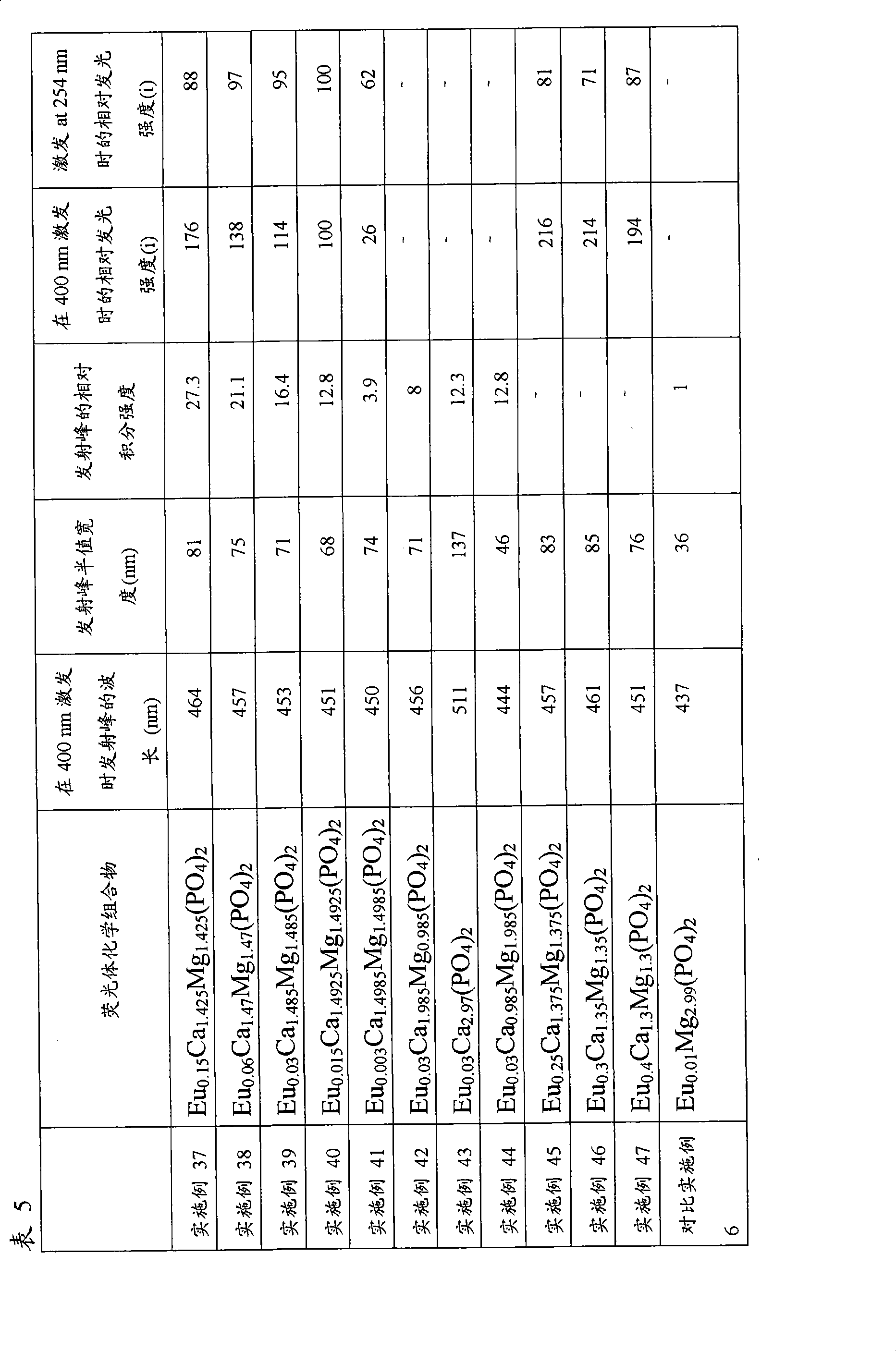
实施例48Example 48
除了改变CaHPO4,CaCO3,MgHPO4,MgCO3和Eu2O3的量,按类似于实施例37的方式制得荧光体EuxCa(1.5-0.5x)Mg(1.5-0.5x)(PO4)2,其x落入0.003-1.5内。所得到的荧光体暴露于254nm和400nm光下测量发光光谱。Except changing the amount of CaHPO 4 , CaCO 3 , MgHPO 4 , MgCO 3 and Eu 2 O 3 , the phosphor Eu x Ca (1.5-0.5x) Mg (1.5-0.5x) ( PO 4 ) 2 , where x falls within 0.003-1.5. The obtained phosphor was exposed to light of 254 nm and 400 nm to measure the emission spectrum.
图36中,示出了当荧光体各自在254nm和400nm激发时的x和发光强度之间的关系。In FIG. 36 , the relationship between x and luminous intensity when the phosphors are each excited at 254 nm and 400 nm is shown.
此处相对发光强度(ii)的意思是假定在254nm和400nm的最大发光强度各自为1时,在浓度x的发光强度。The relative luminous intensity (ii) here means the luminous intensity at the concentration x assuming that the maximum luminous intensities at 254 nm and 400 nm are each 1.
由图36发现发现在400nm和254nm激发的最大发光强度下,Eu浓度(摩尔数)x分别为0.25和0.015,前者大于后者。也发现在实施例37,和45-47中,每个获得的荧光体的Eu浓度至少1.1倍于254nm激发时在最大发光强度的Eu浓度(0.015),并且落入0.5-9倍当400nm激发时在最大发光强度的Eu浓度(0.25)范围内。It is found from Fig. 36 that under the maximum luminous intensity excited by 400nm and 254nm, the Eu concentration (mole number) x is 0.25 and 0.015 respectively, and the former is greater than the latter. It was also found that in Examples 37, and 45-47, the Eu concentration of each obtained phosphor was at least 1.1 times the Eu concentration (0.015) at the maximum luminous intensity when excited at 254 nm, and fell within 0.5-9 times when excited at 400 nm. It is within the range of the Eu concentration (0.25) of the maximum luminous intensity.
虽然详细地描述本发明或参照特定的具体实施方式描述本发明,对本领域普通技术人员而言,在不偏离本发明精神和范围内,可以有各种变化和更改。Although the present invention has been described in detail or with reference to specific embodiments, various changes and modifications can be made by those skilled in the art without departing from the spirit and scope of the present invention.
本申请基于申请于2002年2月15日的日本专利申请(专利申请第2002-038705号),申请于2002年2月27日的日本专利申请(专利申请第2002-050938号),申请于2002年4月30日的日本专利申请(专利申请第2002-129143号),申请于2002年7月24日的日本专利申请(专利申请第2002-214992号),申请于2002年11月29日的日本专利申请(专利申请第2002-348200号),和申请于2003年1月10日的日本专利申请(专利申请第2003-004521号),其在此引为参考。This application is based on the Japanese patent application (patent application No. 2002-038705) filed on February 15, 2002, and the Japanese patent application (patent application No. 2002-050938) filed on February 27, 2002, filed in 2002 Japanese patent application (patent application No. 2002-129143) on April 30, 2002, Japanese patent application (patent application No. 2002-214992) on July 24, 2002, and application on November 29, 2002 Japanese Patent Application (Patent Application No. 2002-348200), and Japanese Patent Application (Patent Application No. 2003-004521 ) filed on January 10, 2003, which are incorporated herein by reference.
工业实用性Industrial Applicability
本发明使得提供具有高的发光强度的光发射器件和具有高的发光强度和良好色彩保留性能的光发射器件成为可能。The present invention makes it possible to provide a light-emitting device with high luminous intensity and a light-emitting device with high luminous intensity and good color retention.
Claims (18)
Applications Claiming Priority (12)
| Application Number | Priority Date | Filing Date | Title |
|---|---|---|---|
| JP2002038705 | 2002-02-15 | ||
| JP038705/02 | 2002-02-15 | ||
| JP050938/02 | 2002-02-27 | ||
| JP2002050938 | 2002-02-27 | ||
| JP129143/02 | 2002-04-30 | ||
| JP2002129143 | 2002-04-30 | ||
| JP214992/02 | 2002-07-24 | ||
| JP2002214992A JP4380118B2 (en) | 2002-07-24 | 2002-07-24 | LIGHT EMITTING DEVICE AND LIGHTING DEVICE USING THE SAME |
| JP348200/02 | 2002-11-29 | ||
| JP2002348200 | 2002-11-29 | ||
| JP004521/03 | 2003-01-10 | ||
| JP2003004521 | 2003-01-10 |
Related Parent Applications (1)
| Application Number | Title | Priority Date | Filing Date |
|---|---|---|---|
| CNB03808323XA Division CN100468789C (en) | 2002-02-15 | 2003-02-13 | Light emitting device and illuminator using the same |
Publications (2)
| Publication Number | Publication Date |
|---|---|
| CN101420004A true CN101420004A (en) | 2009-04-29 |
| CN101420004B CN101420004B (en) | 2012-07-04 |
Family
ID=27739483
Family Applications (2)
| Application Number | Title | Priority Date | Filing Date |
|---|---|---|---|
| CNB03808323XA Expired - Fee Related CN100468789C (en) | 2002-02-15 | 2003-02-13 | Light emitting device and illuminator using the same |
| CN2008101687701A Expired - Fee Related CN101420004B (en) | 2002-02-15 | 2003-02-13 | Light emitting device and illuminator using the same |
Family Applications Before (1)
| Application Number | Title | Priority Date | Filing Date |
|---|---|---|---|
| CNB03808323XA Expired - Fee Related CN100468789C (en) | 2002-02-15 | 2003-02-13 | Light emitting device and illuminator using the same |
Country Status (6)
| Country | Link |
|---|---|
| US (1) | US7357882B2 (en) |
| EP (4) | EP1942531B1 (en) |
| CN (2) | CN100468789C (en) |
| AU (1) | AU2003211509A1 (en) |
| DE (2) | DE60332676D1 (en) |
| WO (1) | WO2003069686A1 (en) |
Families Citing this family (29)
| Publication number | Priority date | Publication date | Assignee | Title |
|---|---|---|---|---|
| EP1715023B1 (en) * | 2004-01-16 | 2012-10-24 | Mitsubishi Chemical Corporation | Phosphor and including the same, light emitting apparatus, illuminating apparatus and image display |
| CN100558850C (en) * | 2004-06-18 | 2009-11-11 | 大电株式会社 | Phosphor and light-emitting element using the same |
| JP3754701B2 (en) * | 2004-06-18 | 2006-03-15 | 大電株式会社 | Phosphor and light emitting device using the same |
| JP5226929B2 (en) | 2004-06-30 | 2013-07-03 | 三菱化学株式会社 | LIGHT EMITTING ELEMENT, LIGHTING DEVICE USING SAME, AND IMAGE DISPLAY DEVICE |
| EP1780592A4 (en) * | 2004-06-30 | 2014-07-09 | Mitsubishi Chem Corp | LIGHT EMITTING DEVICE, BACKLIGHT UNIT FOR LIGHTING DISPLAY UNIT, AND DISPLAY UNIT |
| JP2006019409A (en) | 2004-06-30 | 2006-01-19 | Mitsubishi Chemicals Corp | LIGHT EMITTING DEVICE, LIGHTING USING SAME, DISPLAY BACKLIGHT AND DISPLAY |
| WO2006008935A1 (en) | 2004-06-30 | 2006-01-26 | Mitsubishi Chemical Corporation | Phosphor, light-emitting device using same, image display and illuminating device |
| JP4890017B2 (en) * | 2005-01-26 | 2012-03-07 | 株式会社小糸製作所 | Blue light emitting phosphor and light emitting module using the same |
| JP4653671B2 (en) | 2005-03-14 | 2011-03-16 | 株式会社東芝 | Light emitting device |
| EP1860172A4 (en) * | 2005-03-17 | 2009-01-28 | Hitachi Hppl | DISPLAY DEVICE AND GREEN FLUORESCENT SUBSTANCE |
| JP2006312654A (en) * | 2005-04-07 | 2006-11-16 | Sumitomo Chemical Co Ltd | Phosphor |
| US20090315448A1 (en) * | 2005-04-07 | 2009-12-24 | Sumitomo Chemical Company, Limited | Phosphor, phosphor paste and light emitting device |
| JP2006339605A (en) * | 2005-06-06 | 2006-12-14 | Sumitomo Electric Ind Ltd | Damage evaluation method for compound semiconductor member, method for producing compound semiconductor member, gallium nitride compound semiconductor member, and gallium nitride compound semiconductor film |
| CN101379164B (en) * | 2006-02-10 | 2012-11-21 | 三菱化学株式会社 | Phosphor, production method thereof, phosphor-containing composition, light-emitting device, image display device, and lighting device |
| JP4188404B2 (en) * | 2006-05-19 | 2008-11-26 | 三井金属鉱業株式会社 | White phosphor and white light emitting element or device |
| DE102007018837A1 (en) * | 2007-03-26 | 2008-10-02 | Osram Opto Semiconductors Gmbh | Method for producing a luminescence diode chip and luminescence diode chip |
| WO2009005035A1 (en) * | 2007-06-29 | 2009-01-08 | Mitsubishi Chemical Corporation | Phosphor, method for producing phosphor, phosphor-containing composition, and light-emitting device |
| DE102007060199A1 (en) * | 2007-12-14 | 2009-06-18 | Osram Gesellschaft mit beschränkter Haftung | Fluorescent and illumination system with such phosphor |
| US8471283B2 (en) * | 2008-02-25 | 2013-06-25 | Kabushiki Kaisha Toshiba | White LED lamp, backlight, light emitting device, display device and illumination device |
| JP5284006B2 (en) * | 2008-08-25 | 2013-09-11 | シチズン電子株式会社 | Light emitting device |
| TWI361215B (en) * | 2009-10-12 | 2012-04-01 | Ind Tech Res Inst | Phosphors, fabricating method thereof, and light emitting device employing the same |
| CN102134486B (en) * | 2010-01-26 | 2014-01-29 | 海洋王照明科技股份有限公司 | Vacuum ultraviolet induced green emitting phosphor and preparation method thereof |
| MY163118A (en) * | 2010-04-09 | 2017-08-15 | Hitachi Chemical Co Ltd | Spherical phosphor, wavelength conversion-type photovoltaic cell sealing material, photovoltaic cell module, and production methods therefor |
| JP5870256B2 (en) * | 2013-04-09 | 2016-02-24 | パナソニックIpマネジメント株式会社 | Phosphor and light emitting device |
| CN103382390B (en) * | 2013-07-11 | 2017-07-18 | 中国科学院福建物质结构研究所 | A kind of white light LEDs phosphate phosphor and its preparation |
| CN107209419B (en) * | 2015-02-04 | 2022-08-12 | 默克专利股份有限公司 | Electro-optical switching elements and display devices |
| WO2018049050A1 (en) * | 2016-09-07 | 2018-03-15 | The Regents Of The University Of California | MONOLITHIC TRANSLUCENT BaMgAl10O17:Eu2+ PHOSPHORS FOR LASER-DRIVEN SOLID STATE LIGHTING |
| EP3889239B1 (en) | 2016-10-11 | 2023-08-30 | Seoul Semiconductor Co., Ltd. | Phosphor and production method therefor |
| CN111925683B (en) * | 2020-08-27 | 2022-12-06 | 兰州大学 | Fluorescent whitening automotive paint based on BAM EM and preparation method thereof |
Family Cites Families (41)
| Publication number | Priority date | Publication date | Assignee | Title |
|---|---|---|---|---|
| NL6808847A (en) * | 1968-06-22 | 1969-12-24 | ||
| US3651363A (en) * | 1968-12-23 | 1972-03-21 | Sylvania Electric Prod | Divalent europium-activated barium-magnesium pyrosilicate |
| SE364160B (en) | 1969-05-26 | 1974-02-11 | Western Electric Co | |
| US3699478A (en) | 1969-05-26 | 1972-10-17 | Bell Telephone Labor Inc | Display system |
| US3691482A (en) | 1970-01-19 | 1972-09-12 | Bell Telephone Labor Inc | Display system |
| JPS491221A (en) | 1972-04-17 | 1974-01-08 | ||
| US4075532A (en) * | 1976-06-14 | 1978-02-21 | General Electric Company | Cool-white fluorescent lamp with phosphor having modified spectral energy distribution to improve luminosity thereof |
| JPS60141782A (en) * | 1983-12-29 | 1985-07-26 | Fuji Photo Film Co Ltd | Conversion of radiation image |
| US4786841A (en) * | 1987-06-22 | 1988-11-22 | Gte Products Corporation | Low-pressure arc discharge lamp having increased surface brightness |
| CN1128785A (en) * | 1995-02-06 | 1996-08-14 | 苏勉曾 | Blue fluorescent powder for fluorescent lamp with three primary colors |
| JP3181218B2 (en) * | 1995-09-29 | 2001-07-03 | 松下電器産業株式会社 | Aluminate phosphor, method for producing the same, and device using this phosphor |
| TW383508B (en) | 1996-07-29 | 2000-03-01 | Nichia Kagaku Kogyo Kk | Light emitting device and display |
| US6608332B2 (en) | 1996-07-29 | 2003-08-19 | Nichia Kagaku Kogyo Kabushiki Kaisha | Light emitting device and display |
| JP2927279B2 (en) | 1996-07-29 | 1999-07-28 | 日亜化学工業株式会社 | Light emitting diode |
| CN1137956C (en) * | 1997-02-05 | 2004-02-11 | 中国科学院长春物理研究所 | Preparation of blue fluorescent powder |
| JP2000509912A (en) * | 1997-03-03 | 2000-08-02 | コーニンクレッカ フィリップス エレクトロニクス エヌ ヴィ | White light emitting diode |
| US6051925A (en) | 1997-03-03 | 2000-04-18 | U.S. Philips Corporation | Diode-addressed color display with molecular phosphor |
| JPH10321943A (en) * | 1997-05-15 | 1998-12-04 | Tokyo Inst Of Technol | Thin color display device using vertical cavity surface emitting laser device having single color emission spectrum |
| US6294800B1 (en) * | 1998-02-06 | 2001-09-25 | General Electric Company | Phosphors for white light generation from UV emitting diodes |
| US6255670B1 (en) * | 1998-02-06 | 2001-07-03 | General Electric Company | Phosphors for light generation from light emitting semiconductors |
| US6252254B1 (en) * | 1998-02-06 | 2001-06-26 | General Electric Company | Light emitting device with phosphor composition |
| US6278135B1 (en) * | 1998-02-06 | 2001-08-21 | General Electric Company | Green-light emitting phosphors and light sources using the same |
| JP4350183B2 (en) * | 1998-12-16 | 2009-10-21 | 東芝電子エンジニアリング株式会社 | Semiconductor light emitting device |
| US6273589B1 (en) * | 1999-01-29 | 2001-08-14 | Agilent Technologies, Inc. | Solid state illumination source utilizing dichroic reflectors |
| US6621211B1 (en) * | 2000-05-15 | 2003-09-16 | General Electric Company | White light emitting phosphor blends for LED devices |
| US6501100B1 (en) * | 2000-05-15 | 2002-12-31 | General Electric Company | White light emitting phosphor blend for LED devices |
| CA2380444A1 (en) * | 2000-05-29 | 2001-12-06 | Patent-Treuhand-Gesellschaft Fuer Elektrische Gluehlampen Mbh | Led-based white-emitting illumination unit |
| JP2002042525A (en) * | 2000-07-26 | 2002-02-08 | Toyoda Gosei Co Ltd | Planar light source |
| JP2002038705A (en) | 2000-07-27 | 2002-02-06 | Matsushita Electric Works Ltd | Decorative floor board |
| DE10036940A1 (en) * | 2000-07-28 | 2002-02-07 | Patent Treuhand Ges Fuer Elektrische Gluehlampen Mbh | Luminescence conversion LED |
| JP4585663B2 (en) | 2000-08-04 | 2010-11-24 | 東芝ライテック株式会社 | Filter circuit, filter device and discharge lamp lighting device |
| JP4077170B2 (en) * | 2000-09-21 | 2008-04-16 | シャープ株式会社 | Semiconductor light emitting device |
| JP2002129143A (en) | 2000-10-19 | 2002-05-09 | Nippon Valqua Ind Ltd | Composition for friction surface, sheety molding, and brake lining material |
| JP2002214992A (en) | 2001-01-16 | 2002-07-31 | Konica Corp | Cleaning device, image forming method and image forming device |
| WO2002086978A1 (en) * | 2001-04-20 | 2002-10-31 | Nichia Corporation | Light emitting device |
| US7091656B2 (en) * | 2001-04-20 | 2006-08-15 | Nichia Corporation | Light emitting device |
| JP4480298B2 (en) | 2001-05-24 | 2010-06-16 | 独立行政法人物質・材料研究機構 | Boride crystal, substrate for forming semiconductor layer using the same, and method for producing the same |
| JP2003004521A (en) | 2001-06-27 | 2003-01-08 | Kenwood Corp | Identification device for sound outside vehicle |
| JP2003124526A (en) * | 2001-10-11 | 2003-04-25 | Taiwan Lite On Electronics Inc | White light source manufacturing method |
| US7148520B2 (en) * | 2001-10-26 | 2006-12-12 | Lg Electronics Inc. | Diode having vertical structure and method of manufacturing the same |
| US6717353B1 (en) * | 2002-10-14 | 2004-04-06 | Lumileds Lighting U.S., Llc | Phosphor converted light emitting device |
-
2003
- 2003-02-13 AU AU2003211509A patent/AU2003211509A1/en not_active Abandoned
- 2003-02-13 DE DE60332676T patent/DE60332676D1/en not_active Expired - Lifetime
- 2003-02-13 EP EP08002195A patent/EP1942531B1/en not_active Expired - Lifetime
- 2003-02-13 CN CNB03808323XA patent/CN100468789C/en not_active Expired - Fee Related
- 2003-02-13 DE DE60327926T patent/DE60327926D1/en not_active Expired - Lifetime
- 2003-02-13 EP EP03706938A patent/EP1484803B1/en not_active Expired - Lifetime
- 2003-02-13 CN CN2008101687701A patent/CN101420004B/en not_active Expired - Fee Related
- 2003-02-13 EP EP10003292A patent/EP2204858A3/en not_active Withdrawn
- 2003-02-13 WO PCT/JP2003/001506 patent/WO2003069686A1/en not_active Ceased
- 2003-02-13 EP EP10003293A patent/EP2204859A3/en not_active Withdrawn
-
2004
- 2004-08-16 US US10/918,339 patent/US7357882B2/en not_active Expired - Fee Related
Also Published As
| Publication number | Publication date |
|---|---|
| CN1647286A (en) | 2005-07-27 |
| EP1484803A4 (en) | 2007-05-09 |
| EP1942531B1 (en) | 2010-05-19 |
| WO2003069686A1 (en) | 2003-08-21 |
| DE60327926D1 (en) | 2009-07-23 |
| EP1484803A1 (en) | 2004-12-08 |
| DE60332676D1 (en) | 2010-07-01 |
| EP2204859A3 (en) | 2010-10-27 |
| AU2003211509A1 (en) | 2003-09-04 |
| EP2204858A2 (en) | 2010-07-07 |
| EP1484803B1 (en) | 2009-06-10 |
| US7357882B2 (en) | 2008-04-15 |
| CN101420004B (en) | 2012-07-04 |
| EP1942531A3 (en) | 2008-08-20 |
| EP2204859A2 (en) | 2010-07-07 |
| US20050145854A1 (en) | 2005-07-07 |
| EP1942531A2 (en) | 2008-07-09 |
| CN100468789C (en) | 2009-03-11 |
| EP2204858A3 (en) | 2010-10-27 |
Similar Documents
| Publication | Publication Date | Title |
|---|---|---|
| CN100468789C (en) | Light emitting device and illuminator using the same | |
| US8308982B2 (en) | Alkaline and alkaline earth metal phosphate halides and phosphors | |
| TW200811273A (en) | Illumination system comprising a radiation source and a luminescent material | |
| JP4916651B2 (en) | Light emitting device and phosphor | |
| JP5402008B2 (en) | Phosphor production method, phosphor, and light emitting device using the same | |
| JP4168776B2 (en) | LIGHT EMITTING DEVICE AND LIGHTING DEVICE USING THE SAME | |
| JP4165255B2 (en) | LIGHT EMITTING DEVICE AND LIGHTING DEVICE USING THE SAME | |
| JP2004253747A (en) | Light emitting device and lighting device using the same | |
| JP4389513B2 (en) | Light emitting device, lighting device, and image display device | |
| JP4411841B2 (en) | LIGHT EMITTING DEVICE, LIGHTING DEVICE USING SAME, AND DISPLAY | |
| JP5326986B2 (en) | Phosphor used in light emitting device | |
| JP2010196049A (en) | Phosphor and method for producing the same, phosphor-containing composition, and light-emitting device, image display device and lighting device using the phosphor | |
| JP2016176017A5 (en) | ||
| JP2009173706A (en) | Fluorescent substance, fluorescent substance-containing composition, light emitting apparatus, image display device, and illumination apparatus | |
| JP4706358B2 (en) | Blue light emitting phosphor and method for manufacturing the same, light emitting device, illumination device, backlight for display and display | |
| JP2004235546A (en) | Light emitting device, lighting device and display using the same | |
| JP4972904B2 (en) | Phosphor, method for manufacturing the phosphor, light-emitting device using the phosphor, image display device, and illumination device | |
| JP4561064B2 (en) | Light emitting device, lighting device, and image display device | |
| CN101420005A (en) | Light emitting device and illuminator using the same | |
| JP2010059429A (en) | Phosphor, luminescent device using the same, image display and illuminating device | |
| JP4337465B2 (en) | Light emitting device, lighting device, and image display device | |
| JP4433847B2 (en) | Phosphor, light emitting device using the same, image display device, and illumination device | |
| JP4380118B2 (en) | LIGHT EMITTING DEVICE AND LIGHTING DEVICE USING THE SAME | |
| JP4513287B2 (en) | Light emitting device, lighting device, and image display device |
Legal Events
| Date | Code | Title | Description |
|---|---|---|---|
| C06 | Publication | ||
| PB01 | Publication | ||
| C10 | Entry into substantive examination | ||
| SE01 | Entry into force of request for substantive examination | ||
| C14 | Grant of patent or utility model | ||
| GR01 | Patent grant | ||
| CP01 | Change in the name or title of a patent holder |
Address after: Tokyo, Japan Patentee after: MITSUBISHI CHEMICAL Corp. Address before: Tokyo, Japan Patentee before: MITSUBISHI RAYON Co.,Ltd. |
|
| CP01 | Change in the name or title of a patent holder | ||
| TR01 | Transfer of patent right |
Effective date of registration: 20170911 Address after: Tokyo, Japan Patentee after: MITSUBISHI RAYON Co.,Ltd. Address before: Tokyo, Japan Patentee before: MITSUBISHI CHEMICAL Corp. |
|
| TR01 | Transfer of patent right | ||
| CF01 | Termination of patent right due to non-payment of annual fee |
Granted publication date: 20120704 Termination date: 20190213 |
|
| CF01 | Termination of patent right due to non-payment of annual fee |