CN101379386B - Portable sample analyzer system - Google Patents
Portable sample analyzer system Download PDFInfo
- Publication number
- CN101379386B CN101379386B CN200680053149XA CN200680053149A CN101379386B CN 101379386 B CN101379386 B CN 101379386B CN 200680053149X A CN200680053149X A CN 200680053149XA CN 200680053149 A CN200680053149 A CN 200680053149A CN 101379386 B CN101379386 B CN 101379386B
- Authority
- CN
- China
- Prior art keywords
- sample
- fluid
- flow
- analyser
- pressure
- Prior art date
- Legal status (The legal status is an assumption and is not a legal conclusion. Google has not performed a legal analysis and makes no representation as to the accuracy of the status listed.)
- Expired - Fee Related
Links
Images


Classifications
-
- G—PHYSICS
- G01—MEASURING; TESTING
- G01N—INVESTIGATING OR ANALYSING MATERIALS BY DETERMINING THEIR CHEMICAL OR PHYSICAL PROPERTIES
- G01N35/00—Automatic analysis not limited to methods or materials provided for in any single one of groups G01N1/00 - G01N33/00; Handling materials therefor
- G01N35/08—Automatic analysis not limited to methods or materials provided for in any single one of groups G01N1/00 - G01N33/00; Handling materials therefor using a stream of discrete samples flowing along a tube system, e.g. flow injection analysis
-
- G—PHYSICS
- G01—MEASURING; TESTING
- G01N—INVESTIGATING OR ANALYSING MATERIALS BY DETERMINING THEIR CHEMICAL OR PHYSICAL PROPERTIES
- G01N15/00—Investigating characteristics of particles; Investigating permeability, pore-volume or surface-area of porous materials
- G01N15/10—Investigating individual particles
- G01N15/14—Optical investigation techniques, e.g. flow cytometry
-
- G—PHYSICS
- G01—MEASURING; TESTING
- G01N—INVESTIGATING OR ANALYSING MATERIALS BY DETERMINING THEIR CHEMICAL OR PHYSICAL PROPERTIES
- G01N33/00—Investigating or analysing materials by specific methods not covered by groups G01N1/00 - G01N31/00
- G01N33/48—Biological material, e.g. blood, urine; Haemocytometers
- G01N33/483—Physical analysis of biological material
- G01N33/487—Physical analysis of biological material of liquid biological material
- G01N33/49—Blood
Landscapes
- Health & Medical Sciences (AREA)
- Life Sciences & Earth Sciences (AREA)
- Chemical & Material Sciences (AREA)
- Physics & Mathematics (AREA)
- Engineering & Computer Science (AREA)
- General Health & Medical Sciences (AREA)
- Biomedical Technology (AREA)
- General Physics & Mathematics (AREA)
- Immunology (AREA)
- Pathology (AREA)
- Biochemistry (AREA)
- Analytical Chemistry (AREA)
- Hematology (AREA)
- Ecology (AREA)
- Biophysics (AREA)
- Molecular Biology (AREA)
- Urology & Nephrology (AREA)
- Food Science & Technology (AREA)
- Medicinal Chemistry (AREA)
- Dispersion Chemistry (AREA)
- Investigating Or Analysing Biological Materials (AREA)
Abstract
一种涉及样品分析仪、更具体来讲涉及操作简单且减少向使用者提供错误结果的危险的样品分析仪的系统。在一些情况下,样品分析仪可以是包含一次性流体盒的便携式样品分析仪。分析仪的操作者不需要经过培训。

A system relating to a sample analyzer, and more specifically, to a sample analyzer that is easy to operate and reduces the risk of providing erroneous results to the user. In some cases, the sample analyzer may be a portable sample analyzer containing a disposable fluid cartridge. The operator of the analyzer does not require training.
Description
本申请要求2005年12月22日提交的美国临时专利申请60/753,293的权益。This application claims the benefit of US Provisional Patent Application 60/753,293, filed December 22,2005.
本申请要求2005年12月29日提交的美国临时专利申请60/755,014的权益。This application claims the benefit of US Provisional Patent Application 60/755,014, filed December 29,2005.
本申请是2005年5月12日提交的美国专利申请号10/908,460的部分继续申请,其要求2004年5月14日提交的美国临时申请60/571,235的权益。This application is a continuation-in-part of US Patent Application No. 10/908,460, filed May 12, 2005, which claims the benefit of US Provisional Application 60/571,235, filed May 14, 2004.
本申请是2005年5月12日提交的美国专利申请号10/908,461的部分继续申请,其要求2004年5月14日提交的美国临时申请60/571,235的权益。This application is a continuation-in-part of US Patent Application Serial No. 10/908,461, filed May 12, 2005, which claims the benefit of US Provisional Application 60/571,235, filed May 14, 2004.
本申请是2005年12月30日提交的美国专利申请号11/306,508的部分继续申请,所述申请是2004年9月27日提交的美国专利申请号10/950,898的部分继续申请案。This application is a continuation-in-part of US Patent Application Serial No. 11/306,508, filed December 30, 2005, which is a continuation-in-part of US Patent Application Serial No. 10/950,898, filed September 27, 2004.
本申请是2004年9月9日提交的美国专利申请号10/938,265的部分继续申请。This application is a continuation-in-part of US Patent Application Serial No. 10/938,265, filed September 9,2004.
背景background
本申请总体涉及样品分析仪,更具体来讲涉及操作简单且减少提供错误结果的危险的样品分析仪。The present application relates generally to sample analyzers, and more particularly to sample analyzers that are simple to operate and reduce the risk of providing erroneous results.
化学和/或生物学分析对于生命科学研究、临床诊断及多种环境和过程监测方面都很重要。在一些情况下,用样品分析仪进行和/或辅助进行样品流体的化学和/或生物学分析。根据用途,样品流体可以是液体或气体。Chemical and/or biological analysis is important in life science research, clinical diagnostics, and monitoring of many environments and processes. In some cases, chemical and/or biological analysis of the sample fluid is performed and/or assisted by the sample analyzer. Depending on the application, the sample fluid can be a liquid or a gas.
许多样品分析仪是由专业人员在实验室环境使用的相当大的设备。为了使用许多样品分析仪,在将制备样品用于样品分析仪之前,必须首先处理收集的样品,如将样品稀释至所需水平、加入合适试剂、使样品离心完成所需分离等。为了得到准确结果,通常必须由专业人员进行此类样品处理,这可能增加进行样品分析需要的费用和时间。Many sample analyzers are fairly large devices used by professionals in laboratory settings. In order to use many sample analyzers, the collected sample must first be processed, such as diluting the sample to the desired level, adding appropriate reagents, centrifuging the sample to complete the desired separation, etc., before the prepared sample can be used in the sample analyzer. To obtain accurate results, such sample handling typically must be performed by professionals, which can add to the expense and time required to perform sample analysis.
许多样品分析仪在分析期还需要操作员干预,如需要输入附加信息或另外处理样品。这还可增加进行所需样品分析需要的费用和时间。而且,许多样品分析仪只提供原始的分析数据输出,通常必须由专业人员再进行计算和/或解释才得出合适的临床或其它判断。Many sample analyzers also require operator intervention during the analysis period, such as the need to enter additional information or otherwise process samples. This can also increase the cost and time required to perform the required sample analysis. Furthermore, many sample analyzers provide only raw analytical data output, which often must be recalculated and/or interpreted by a professional to arrive at appropriate clinical or other judgments.
2005年12月22日提交的美国临时专利申请60/753,293通过引用结合到本文中。2005年12月29日提交的美国临时专利申请60/755,014通过引用结合到本文中。2005年5月12日提交的美国专利申请号10/908,460通过引用结合到本文中。2005年5月12日提交的美国专利申请号10/908,461通过引用结合到本文中。2005年12月30日提交的美国专利申请号11/306,508通过引用结合到本文中。2004年9月27日提交的美国专利申请号10/950,898的部分继续申请通过引用结合到本文中。2004年9月9日提交的美国专利申请号10/938,265通过引用结合到本文中。US Provisional Patent Application 60/753,293, filed December 22, 2005, is incorporated herein by reference. US Provisional Patent Application 60/755,014, filed December 29, 2005, is incorporated herein by reference. US Patent Application No. 10/908,460, filed May 12, 2005, is incorporated herein by reference. US Patent Application No. 10/908,461, filed May 12, 2005, is incorporated herein by reference. US Patent Application No. 11/306,508, filed December 30, 2005, is incorporated herein by reference. Continuation-in-Part of US Patent Application Serial No. 10/950,898, filed September 27, 2004, is hereby incorporated by reference. US Patent Application No. 10/938,265, filed September 9, 2004, is incorporated herein by reference.
概述overview
本发明总体涉及样品分析仪,更具体来讲涉及操作简单且减少给使用者提供错误结果的危险的样品分析仪。在一些情况下,样品分析仪可以是包含一次性流体盒的便携式样品分析仪。The present invention relates generally to sample analyzers, and more particularly to sample analyzers that are simple to operate and reduce the risk of providing erroneous results to the user. In some cases, the sample analyzer may be a portable sample analyzer that includes a disposable fluid cartridge.
附图简述Brief description of the drawings
图1是示例性样品分析仪和盒(cartridge)的透视图;Figure 1 is a perspective view of an exemplary sample analyzer and cartridge;
图2是图1示例性样品分析仪和盒的示意图;Figure 2 is a schematic diagram of the exemplary sample analyzer and cartridge of Figure 1;
图3是显示图2样品分析仪和盒的流量控制的更详细示意图;Figure 3 is a more detailed schematic diagram showing the flow control of the sample analyzer and cartridge of Figure 2;
图4是示例性盒某些特征的示意图;Figure 4 is a schematic illustration of certain features of an exemplary cartridge;
图5是可包含在盒内的多个示例性贮存池的示意图;Figure 5 is a schematic diagram of a plurality of exemplary reservoirs that can be contained within a cartridge;
图6是显示分析血样的示例性方法的示意流程图;Figure 6 is a schematic flow diagram showing an exemplary method of analyzing a blood sample;
图7是显示获得多种红细胞参数的示例性方法的流程图;Figure 7 is a flowchart showing an exemplary method of obtaining various red blood cell parameters;
图8是显示分析血样的另一种示例性方法的示意流程图;Figure 8 is a schematic flow diagram showing another exemplary method of analyzing a blood sample;
图9a、9b、9c、9d、9e和9f分别显示针-隔界面(needle-septuminterface)、轴-膜(shaft-membrane)界面和膜-膜界面。Figures 9a, 9b, 9c, 9d, 9e and 9f show the needle-septum interface, shaft-membrane interface and membrane-membrane interface, respectively.
图9g显示推动流(pusher fluid)、溶解溶液(lysing solution)、球化溶液(sphering solution)和鞘流(sheath fluid)空腔直径的表;Figure 9g shows a table of cavity diameters for pusher fluid, lysing solution, sphering solution and sheath fluid;
图10是显示建立和操作样品分析仪的示例性方法的示意流程图;Figure 10 is a schematic flow diagram showing an exemplary method of setting up and operating a sample analyzer;
图11a是显示操作样品分析仪的示例性方法的流程图;Figure 11a is a flowchart showing an exemplary method of operating a sample analyzer;
图11b是显示操作样品分析仪的另一种示例性方法的流程图;FIG. 11 b is a flow chart showing another exemplary method of operating a sample analyzer;
图12是显示操作样品分析仪的另一种示例性方法的流程图;Figure 12 is a flowchart showing another exemplary method of operating a sample analyzer;
图13是示例性光学测量示意图,可用于帮助鉴定流体回路流动通道中何时存在不正确或不需要的流体;13 is a schematic diagram of exemplary optical measurements that can be used to aid in identifying when incorrect or unwanted fluid is present in a fluid circuit flow path;
图14是另一种示例性光学测量的示意图,可用于帮助鉴定流体回路流动通道中何时存在不正确或不需要的流体;14 is a schematic illustration of another exemplary optical measurement that can be used to aid in identifying when incorrect or unwanted fluid is present in a fluid circuit flow path;
图15是电测量示意图,可用于帮助鉴定流体回路流动通道中何时存在不正确或不需要的流体;Figure 15 is a schematic diagram of electrical measurements that can be used to aid in identifying when incorrect or unwanted fluid is present in the flow path of a fluid circuit;
图16是另一种测量示意图,可用于帮助鉴定流体回路流动通道中何时存在不正确或不需要的流体;Figure 16 is another schematic diagram of measurements that can be used to aid in identifying when incorrect or unwanted fluid is present in the flow path of a fluid circuit;
图17是示例性实例的示意图,可用于鉴定流动通道内样品流体何时出现一个或多个气泡或其它不需要的颗粒;17 is a schematic diagram of an illustrative example that can be used to identify when one or more air bubbles or other unwanted particles are present in a sample fluid within a flow channel;
图18是另一种示例性实例示意图,可用于鉴定流动通道内样品流体何时出现一个或多个气泡或其它不需要的颗粒;FIG. 18 is another exemplary schematic diagram that can be used to identify when one or more air bubbles or other unwanted particles are present in a sample fluid within a flow channel;
图19是示例性实例示意图,可用于鉴定流动通道内样品流体何时出现一个或多个气泡或其它不需要的特征;Figure 19 is a schematic diagram of an illustrative example that can be used to identify when one or more air bubbles or other unwanted characteristics are present in a sample fluid within a flow channel;
图20显示压力源可将示例性压力脉冲900提供给图19流动通道中的样品流体;FIG. 20 shows that a pressure source can provide an
图21是示例性实例示意图,可有助于确定或估计流体回路流动通道中样品流体末端或远端的位置;FIG. 21 is a schematic diagram of an illustrative example that may be useful in determining or estimating the position of a sample fluid end or distal end in a flow path of a fluid circuit;
图22-23是示例性实例示意图,可用于确定两种或多种流体何时在流体回路下游汇集;22-23 are schematic diagrams of illustrative examples that may be used to determine when two or more fluids combine downstream of a fluid circuit;
图24是示例性仪器和盒的示意图,其中盒和仪器是匹配的(keyed),只允许盒以正确的方向插入仪器内;Figure 24 is a schematic diagram of an exemplary instrument and cartridge, where the cartridge and instrument are keyed, only allowing the cartridge to be inserted into the instrument in the correct orientation;
图25是示例性盒示意图;Figure 25 is a schematic diagram of an exemplary cartridge;
图26是包含弹簧推动式刺血针(spring activated lancet)的示例性盒示意图;26 is a schematic diagram of an exemplary cartridge containing a spring activated lancet;
图27是具有清除流动通道中气泡的膜的示例性盒示意图;和Figure 27 is a schematic diagram of an exemplary cartridge with a membrane that clears air bubbles in the flow channel; and
图28是流动通道气泡捕获器的示例性实例示意图。28 is a schematic illustration of an illustrative example of a flow channel bubble trap.
详述detail
本发明涉及样品分析仪,更具体来讲涉及操作简单且减少提供错误结果的危险的样品分析仪,在一些情况下,根据需要,样品分析仪可以是例如血液分析仪如流式细胞仪、血液学分析仪、临床化学分析仪(如葡萄糖分析仪、离子分析仪、电解质分析仪、溶解气体分析仪等)、尿液分析仪或任何其它合适的分析仪。The present invention relates to sample analyzers, and more particularly to sample analyzers that are simple to operate and reduce the risk of providing erroneous results. In some cases, sample analyzers may be, for example, blood analyzers such as flow cytometers, blood Chemical analyzers, clinical chemistry analyzers (such as glucose analyzers, ion analyzers, electrolyte analyzers, dissolved gas analyzers, etc.), urine analyzers, or any other suitable analyzers.
如果本发明符合某些要求,则其自身或用其进行的测试可免受法规监管。可实施本发明以提供和/或进行可以是实验室检验和规程的测试,所述测试简单且准确,以致提供错误结果的可能性可忽略不计,或者在不正确进行测试时不会产生可推知的伤害患者的风险。一种豁免类型可来自1988年的临床实验室改进修正案(CLIA)。If the invention meets certain requirements, it may be exempt from regulation, either by itself or by tests performed with it. The invention may be practiced to provide and/or perform tests, which may be laboratory tests and procedures, which are simple and accurate so as to provide negligible chance of erroneous results, or produce no inferable results when performed incorrectly. risk of harming the patient. One type of waiver is available from the Clinical Laboratory Improvement Amendments (CLIA) of 1988.
图1是流式细胞仪透视图。描述流式细胞分析仪只用于举例说明的目的,预期必要时可适用于其它类型样品分析仪。示例性样品分析仪通常如10显示,包括外壳12和活动式或一次性盒14。示例性外壳12包括基板16、盖18和将基板16与盖18连接的铰链20,但这不一定需要。在示例性实例中,基板16包括第一光源22a、第二光源22b和第三光源22c、以及关联的光学器件和操作样品分析仪需要的电子设备。每个光源可以是单光源或多光源,取决于用途。在一些情况下,外壳的整体尺寸小于1立方英尺、小于1/2立方英尺、小于1/4立方英尺或必要时更小。同样,外壳的整体重量可小于10磅、小于5磅、小于1磅或必要时更小。Figure 1 is a perspective view of a flow cytometer. The flow cytometer is described for illustrative purposes only, and it is contemplated that other types of sample analyzers can be adapted as necessary. An exemplary sample analyzer is shown generally at 10 including a housing 12 and a removable or
示例性盖12包括压力源(如具有控制微阀的压力室)、第一光检测器24a、第二光检测器22b和第三光检测器22c,各自具有关联光学器件和电子设备。每个光检测器也可以是单光检测器或多光检测器,取决于用途。如果需要,可根据用途提供偏振器和/或滤片。The exemplary cover 12 includes a pressure source (eg, a pressure chamber with a controlled microvalve), a first light detector 24a, a second light detector 22b, and a third light detector 22c, each with associated optics and electronics. Each photodetector can also be a single photodetector or a multiple photodetector, depending on the application. Polarizers and/or filters are available depending on the application, if required.
示例性活动式盒14适合通过样品收集口接收样品流体,在示例性实例中收集口包括刺血针32。在一些情况下,刺血针32是可缩回的和/或装有弹簧的。当活动式盒14不使用时,帽38可用于保护样品收集口和/或刺血针32。Exemplary
在示例性实例中,活动式盒14对全血样品进行血液分析。刺血针32可用于刺穿使用者手指得到血液样品,将其通过毛细管作用吸入活动式盒14中的有抗凝剂涂层的毛细管内。活动式盒14可由流体回路构成,其中一些流体回路用具有蚀刻通道的层状结构形成。然而,如果需要,预期可通过任何合适方式包括注塑或任何其它合适的制备过程或方法构成活动式盒14。In the illustrative example,
使用时,在已将血样吸入活动式盒14后,可将活动式盒14插入外壳内。在一些情况下,可在盖18处于开放位置时将活动式盒14插入外壳内。然而,在其它情况下,可通过任何合适的方式将活动式盒14插入外壳内。例如,外壳可具有槽缝,可将活动式盒14插入外壳的槽缝内。In use, the
回顾图1的示例性实例,活动式盒14可包括接收基板16中定位插销28a和28b的孔眼26a和26b,可帮助对准和联接仪器的不同部分。活动式盒14还可包括第一透明流动窗30a、第二透明流动窗30b和第三透明窗30c,分别对准第一、第二和第三光源22a、22b和22c以及第一、第二和第三光检测器24a、24b和24c。Referring back to the illustrative example of FIG. 1 ,
当盖移动成关闭位置且系统加压时,盖18可分别通过压力供给口36a、36b、36c和36d将控制压力提供至示例性活动式盒14中的压力接收口34a、34b、34c和34d。根据用途,预期可使用更多或更少压力供给和压力接收口。或者或另外,预期可将一个或多个微泵如静电致动微量泵(meso pump)提供在活动式盒14上或其中,为活动式盒14提供操作流体回路的必需压力。一些示例性静电致动微量泵描述于例如美国专利号5,836,750、6,106,245、6179,586、6,729,856和6,767,190,这些专利全部转让给本发明受让人,全部通过引用结合到本文中。When the lid is moved into the closed position and the system is pressurized, the
一旦加压,示例性仪器即可对收集的血样进行血液分析。在一些情况下,血液分析可包括全血细胞计数(CBC)分析,但可根据用途进行其它类型分析。Once pressurized, the exemplary instrument can perform blood analysis on the collected blood sample. In some cases, blood analysis may include a complete blood count (CBC) analysis, although other types of analysis may be performed depending on the application.
为了对红细胞计数和分类,可将部分全血样品分出并提供至活动式盒14的红细胞测量通道。然后如果需要,可稀释血样,红细胞实时(on the fly)形成球形,所得样品可呈流体动力学集中,形成核心,最终提供至第一细胞计量通道。第一细胞计量通道可沿活动式盒14的第一透明流动窗30a定位,以便流体细胞可被第一光源22a和第一光检测器24a光学询探。在一些情况下,可将第一流量传感器提供于活动式盒14上,测量通过第一细胞计量通道的流速。To count and classify red blood cells, a portion of the whole blood sample may be split and provided to the red blood cell measurement channel of the
在一些情况下,测量参数可包括例如样品流速(FR)、测量时间(T)持续时间、样品稀释系数(DF)、红细胞计数(NRB)、血小板计数(NPlt)、各细胞直径(drbc)和各细胞血红蛋白浓度(CHC)。从这些参数,可计算许多红细胞分析参数,包括如红细胞计数(RBC=NRB/(DF×FR×T))、血小板计数(Plt=Nplt(DF×FR×T))、平均细胞血红蛋白浓度(MCHC=<CHC>)、平均细胞体积(MCV=(π/6)×<drbc3>)、平均细胞血红蛋白含量(MCH=(π/6)×<drbc3×CHC>)、相对分布宽度(RDW=[(π/6)×drbc3]/MCV的标准差)、红细胞压积参数(Hct=RBC×MCV)和/或血红蛋白浓度(Hb=MCHC×Hct)。In some cases, measurement parameters may include, for example, sample flow rate (FR), measurement time (T) duration, sample dilution factor (DF), red blood cell count (N RB ), platelet count (N Plt ), individual cell diameters (drbc ) and each cell hemoglobin concentration (CHC). From these parameters, a number of red blood cell analysis parameters can be calculated including, for example, red blood cell count (RBC = N RB /(DF x FR x T)), platelet count (Plt = N plt (DF x FR x T)), mean cell hemoglobin concentration (MCHC=<CHC>), mean cell volume (MCV=(π/6)×<drbc 3 >), mean cell hemoglobin content (MCH=(π/6)×<drbc 3 ×CHC>), relative distribution width (RDW=[(π/6)×drbc 3 ]/standard deviation of MCV), hematocrit parameters (Hct=RBC×MCV) and/or hemoglobin concentration (Hb=MCHC×Hct).
在一些实例中,还将一些血样导向吸收测量通道。吸收测量通道可沿活动式盒14的第三透明窗30c定位,以便血样可被第三光源22c和第三光检测器24c光学询探。可将流量传感器提供在活动式盒14上,测量进入或通过吸收测量通道的流速。吸收测量通道可测量由第三光源22c提供的入射光的吸收。可将测量的吸收水平提供为血样中总体或平均细胞血红蛋白浓度读数。In some instances, some blood samples are also directed to the absorption measurement channel. An absorption measurement channel can be positioned along the third transparent window 30c of the
为了对白细胞计数和分类,可将部分全血样品分出并提供至活动式盒14的白细胞测量通道。然后如果需要,可稀释血样,红细胞可实时溶解,所得样品可呈流体动力学集中,形成核心,最终提供至第二细胞计量通道。第二细胞计量通道可沿活动式盒14的第二透明流动窗30b定位,以便流体细胞可被第二光源22b和第二光检测器24b光学询探。可将流量传感器提供在活动式盒14上以测量通过第二细胞计量通道的流速。在一些情况下,测量的白细胞参数可包括例如三(3)或(5)部份白细胞区分、总白细胞计数和/或正轴(on-axis)白细胞体积。根据用途还可测量或计算其它参数。To count and classify white blood cells, a portion of the whole blood sample may be split and provided to the white blood cell measurement channel of the
图1显示一种示例性样品分析仪和盒组装体。然而,预期可使用其它样品分析仪配置。例如,样品分析仪10和活动式盒可类似于授予Schwichtenberg等的美国专利申请2004/0211077的描述,其通过引用结合到本文中。Figure 1 shows an exemplary sample analyzer and cartridge assembly. However, it is contemplated that other sample analyzer configurations may be used. For example, the sample analyzer 10 and removable cartridge may be similar to that described in US Patent Application 2004/0211077 to Schwichtenberg et al., which is incorporated herein by reference.
在一些情况下,样品分析仪10适合在患者护理点如医师诊所、家居或现场其它地方使用。样品分析仪10只需要很少或不需要专业培训即可在实验室环境外可靠地使用,有了这种样品分析仪10可帮助样品分析过程流线化,减少费用和医务人员负担,增加分析许多患者样品的方便性,包括需要相对频繁监测/分析血液的患者。In some cases, sample analyzer 10 is suitable for use at the point of patient care, such as a physician's office, at home, or elsewhere in the field. With the sample analyzer 10 requiring little or no specialized training for reliable use outside of a laboratory environment, the sample analyzer 10 can help streamline the sample analysis process, reduce costs and burden on medical staff, and increase analysis Convenience for many patient samples, including those requiring relatively frequent monitoring/analysis of blood.
操作时,样品分析仪10可接收收集的样品,如收集的全血,一旦启动分析仪,样品分析仪10可自动处理样品,为使用者提供作出临床判断的信息。在一些实例中,样品分析仪10可显示或打印出定量结果(如在预定范围之内和/或之外),以便使用者不需要再计算或解释。In operation, sample analyzer 10 may receive a collected sample, such as collected whole blood, and upon activation of the analyzer, sample analyzer 10 may automatically process the sample to provide the user with information for making a clinical decision. In some examples, sample analyzer 10 may display or print out quantitative results (eg, within and/or outside predetermined ranges) so that no further calculations or interpretations are required by the user.
图2是图1示例性样品分析仪和盒的示意图。如上文详述,在示例性实例中,基板16可包括多个光源22、关联的光学器件和操作分析仪必需的控制和处理用电子设备40。基板16还可包括电池42、变压器或其它电源。所示盖12具有压力源/流量控制块44和具有关联光学器件的多个光检测器24。Figure 2 is a schematic diagram of the exemplary sample analyzer and cartridge of Figure 1 . As detailed above, in the illustrative example,
活动式盒14可通过样品收集口或刺血针32接收样品流体。当压力源/流量控制块44加压时,活动式盒14可对接收血样进行血液分析。在一些实例中,如上文描述,活动式盒14可包括多种试剂49,和使试剂与血样混合制备分析血样的流体回路。而且,在一些情况下,活动式盒14可包括帮助控制和/或检验流体回路是否正确运行的多个流量传感器。The
在一些情况下,制备(如溶解、球化、染色、稀释和/或其它处理)血样,然后在一个或多个随带的(on-board)细胞计量通道如细胞计量通道50中流体动力学集中,形成核心。在示例性实例中,细胞计量通道50经过活动式盒14的透明流动窗如第一透明流动窗30a。基板16中一系列光源22和关联光学器件可经由流动窗30a使光通过核心流体。一系列光检测器24和关联光学器件也可经由流动窗30a接收核心的散射和非散射光。控制器或处理器40可接收来自检测器24阵列的输出信号,可对核心流体中存在的所选细胞进行区分和/或计数。In some cases, blood samples are prepared (e.g., lysed, spheroidized, stained, diluted, and/or otherwise processed) and then hydrodynamically concentrated in one or more on-board cytometry channels, such as
预期活动式盒14可包括流体控制块48,帮助控制活动式盒14中至少一些流体的速度。在示例性实例中,流体控制块48包括可测知各种流体的速度并将速度报告至控制器或处理器40的流量传感器。然后控制器或处理器40可调节一种或多种控制信号,将其提供给压力源/流量控制块44,达到所需压力,从而获得正确操作分析仪的所需流体速度。It is contemplated that the
因为血液及其它生物学废液可传播疾病,所以活动式盒14可包括废液池52,位于示例性细胞计量通道50下游。废液池52可接收和贮存活动式盒14中的流体。当测试完成时,可取出分析仪的活动式盒14,例如丢弃在与生物学废液相容的容器内。Because blood and other biological waste fluids can transmit disease, the
图3是更详细的示意图,显示图2样品分析仪和盒的流量控制。在示例性实例中,盖18的压力源/流量控制器44提供5种控制压力,包括样品推动(P)压力36a、溶解(L)压力36b、球化(SP)压力36c、鞘流(SH)压力36d和稀释(D)压力36e。这些只用于举例说明,根据用途,预期压力源/流量控制器44可提供更多、更少或不同的压力(如对染色池的染色压力)。而且,预期盖18可根本不包括压力源/流量控制器44。取而代之的是,根据需要,活动式盒14可包括随带的压力源如压缩空气池、一个或多个微泵如上述静电致动微量泵或者任何其它合适的压力源。光源和检测器阵列不在图3显示。Figure 3 is a more detailed schematic showing the flow control of the Figure 2 sample analyzer and cartridge. In the illustrative example, pressure source/flow controller 44 of
在示例性实例中,压力源36a经过推动流65将压力提供至血样池62,压力源36b提供压力至溶解池64,压力源36c提供压力至球化池66,压力源36d提供压力至鞘流池68,压力源36e提供压力至稀释池70。In the illustrative example, pressure source 36a provides pressure to blood sample reservoir 62 via
在一个示例性实例中,每个压力源可包括接收输入压力的第一压力室,和提供控制压力至活动式盒的第二压力室。第一阀门可位于第一压力室与第二压力室之间,用于将第一压力室的压力可控地释放至第二压力室内。与第二压力室流体相通的第二阀门可将第二压力室的压力可控地释放至大气中。这可允许压力源/流量控制器44将控制压力提供至活动式盒14上每个压力接收口。各阀门可以是可个别操作和控制的静电致动微阀阵列,如描述于如美国专利号6,240,944,其通过引用结合到本文中。或者,各阀门可以是静电致动微阀阵列,所述微阀由控制的工作周期脉冲性调节,实现控制“有效”的流速或漏速(leak rate)。如果需要,也可使用其它阀门。In one illustrative example, each pressure source may include a first pressure chamber that receives an input pressure, and a second pressure chamber that provides a control pressure to the removable cartridge. A first valve may be located between the first pressure chamber and the second pressure chamber for controllably releasing pressure from the first pressure chamber into the second pressure chamber. A second valve in fluid communication with the second pressure chamber can controllably release the pressure of the second pressure chamber to atmosphere. This may allow the pressure source/flow controller 44 to provide control pressure to each pressure receiving port on the
示例性活动式盒14包括5个压力接收口34a、34b、34c、34d和34e,各自接收来自压力源/流量控制器44的相应的控制压力。在示例性实例中,压力接收口34a、34b、34c、34d和34e分别将控制压力传递至贮血池62、溶解池64、球化池66、鞘流池68和稀释池70。在活动式盒14装配好供使用之前,可填充溶解池64、球化池66、鞘流池68和稀释池70,而通过样品收集口或刺血针32现场填充贮血池62。The exemplary
如图所示,流量传感器可提供在每种或所选流体线路内。各流量传感器80a-80e可测量相应流体的速度。流量传感器80a-80e可以是热气流速型(thermal anemometer type)流量传感器和微桥型流量传感器。微桥流量传感器描述于如美国专利号4,478,076、美国专利号4,478,077、美国专利号4,501,144、美国专利号4,651,564、美国专利号4,683,159和美国专利号5,050429,通过引用全部结合到本文中。As shown, flow sensors may be provided within each or selected fluid lines. Each flow sensor 80a-80e may measure the velocity of a corresponding fluid. The flow sensors 80a-80e may be thermal anemometer type flow sensors and microbridge type flow sensors. Microbridge flow sensors are described, for example, in US Patent No. 4,478,076, US Patent No. 4,478,077, US Patent No. 4,501,144, US Patent No. 4,651,564, US Patent No. 4,683,159, and US Patent No. 5,050429, all of which are incorporated herein by reference.
或者或另外,传感器80a-80e可用于检测流体的一种或多种特征,如导热率、比热、流体密度、电阻率和/或其它流体特征,如帮助鉴定或验证正在穿过流动通道的流体是预期流体或预期流体类型。这可帮助验证具体分析或操作时用于流动通道的确实是预期流体。可用控制器按程序检测预期流体是否确实用于流动通道,在一些情况下,发出警告和/或切断样品分析仪。Alternatively or in addition, sensors 80a-80e may be used to detect one or more characteristics of the fluid, such as thermal conductivity, specific heat, fluid density, resistivity, and/or other fluid characteristics, such as to help identify or verify the fluid being passed through the flow channel. Fluid is the expected fluid or expected fluid type. This can help verify that the intended fluid is indeed being used for the flow channel for a particular analysis or operation. The controller can be programmed to detect whether the intended fluid is actually used in the flow path, and in some cases, issue a warning and/or shut down the sample analyzer.
可将各流量传感器80a-80e的输出信号提供至控制器或处理器40。如图所示,控制器或处理器40可将控制信号提供至压力源/控制器44。例如,为了控制向血样施加的压力,当血样速度下降至低于第一预定值时,控制器或处理器40可打开压力源/控制器44中第一压力室与第二压力室之间的第一阀门,将第一压力室的压力可控地释放至第二压力室。同样,当血样速度增加至高于第二预定值时,控制器或处理器40可打开第二阀门,放出第二压力室的压力。控制器或处理器40可通过类似方式控制溶解剂、球化剂、鞘流和稀释剂的速度。The output signal of each flow sensor 80a - 80e may be provided to a controller or
在一些情况下,控制器或处理器40可检测穿过流动通道流速的一种或多种改变。流速改变可归因于例如,流动通道中一个或多个气泡、如血样凝固引起的流动通道闭塞或部分闭塞、流动通道中不需要或外来的物体和/或流动通道的其它不良特征。在一些情况下,可使用上升时间、下降时间或流速的一些其它特征。可使控制器或处理器40按程序检测流速的此类特征,在一些情况下,发出警告和/或切断样品分析仪。In some cases, controller or
热气流速型流量传感器通常包括加热元件(当供能时可在流体中产生一个或多个热脉冲),还包括一个或多个热传感器(位于加热元件上游和/或下游以检测一个或多个热脉冲)。流体穿过流动通道的速度可能与热脉冲从加热元件到达一个间隔热传感器需要的时间相关。Hot gas velocity flow sensors typically include a heating element (which when energized generates one or more heat pulses in the fluid) and one or more thermal sensors (located upstream and/or downstream of the heating element to detect one or more heat pulse). The velocity of the fluid through the flow channel may be related to the time required for a heat pulse to travel from the heating element to a spaced thermal sensor.
在一些情况下,热气流速型流量传感器可用于检测流体导热性和/或比热。流体导热性和/或比热的改变可对应于流体特征的改变,如流体状态的改变(血样凝固)、流体气泡、流体中不需要或外来物体等。或者或另外,热气流速型流量传感器可用于检测一种或多种流体特征如导热性、比热等,以便例如帮助鉴定或验证穿过流动通道的流体是预期流体或预期流体类型。这可帮助验证具体分析或操作时用于流动通道的确实是预期流体。在一些实例中,预期控制器或处理器40可通过监测经过热气流速型流量传感器的流体的导热性和/或比热检测流体特征。可使控制器或处理器40按程序检测例如流体的不良特征(如气泡),和/或预期流体是否确实用于流动通道,在一些情况下,发出警告和/或切断样品分析仪。In some cases, hot gas velocity type flow sensors may be used to detect fluid thermal conductivity and/or specific heat. Changes in the thermal conductivity and/or specific heat of the fluid may correspond to changes in the characteristics of the fluid, such as changes in the state of the fluid (clotting of the blood sample), air bubbles in the fluid, unwanted or foreign objects in the fluid, and the like. Alternatively or additionally, a hot gas velocity type flow sensor may be used to detect one or more fluid characteristics such as thermal conductivity, specific heat, etc., for example, to help identify or verify that the fluid passing through the flow channel is the intended fluid or type of fluid. This can help verify that the intended fluid is indeed being used for the flow channel for a particular analysis or operation. In some examples, it is contemplated that the controller or
在一些情况下,可提供阻抗传感器与流动通道流体相通。可使控制器或处理器40与阻抗传感器联接。流体阻抗的改变可提示流体特征的改变,如流体状态改变(血样凝固)、流体气泡、流体中不需要或外来的物体、正确的流体类型等。因此,在一些实例中,预期控制器或处理器40可通过监测经过阻抗传感器的流体阻抗检测流体特征。In some cases, an impedance sensor may be provided in fluid communication with the flow channel. A controller or
还可提供大体在110显示的下游阀。控制器或处理器40可根据需要开放/关闭下游阀110。例如,下游阀110可保持关闭直至系统完全加压。这可帮助防止血液、溶解剂、球化剂、鞘流和稀释剂在系统完全加压之前流入流体回路86中。而且,可控制下游阀110帮助进行某些测试,如零流量测试等。在另一个实例中,例如当盖关闭时,可通过机械作用开放下游阀110。A downstream valve, shown generally at 110, may also be provided. The controller or
图4是示例性活动式盒某些特征的示意图。示例性活动式盒总体如100显示,可类似于图1-3显示和描述的活动式盒14。应理解活动式盒100只用于举例说明,本实例可适用于许多微流体盒,不管其形式、功能或配置如何。例如,本实例可适用于适合流式细胞术、血液学、临床化学、血液化学分析、尿液分析、血气分析、病毒分析、细菌分析、电解质测量等的活动式盒。还预期可用任何合适材料或材料系统(例如玻璃、硅、一种或多种聚合物或任何其它合适材料或材料系统)或者材料或材料系统组合制备本系统的活动式盒如活动式盒100。Figure 4 is a schematic illustration of certain features of an exemplary removable cartridge. An exemplary mobile cassette, shown generally at 100, may be similar to
示例性活动式盒100包括第一测量通道102和第二测量通道104,但根据需要可使用更多或更少测量通道。在示例性实例中,第一测量通道102是红细胞测量通道,第二测量通道104是白细胞测量通道。活动式盒100通过血液接收口106接收全血样品,通过毛细管作用,将已知量血液吸入有抗凝剂涂层的血样贮存毛细管108内。将样品推动(P)压力,如图3的样品推动(P)压力36a,提供至样品推动流体池,如图3的样品推动流体池65。当施加压力时,迫使样品推动流从样品推动流体池进入血样推动通道110内The exemplary
在一些示例性实例中,可将阀门112和流量传感器114提供在血样推动通道110线路内。在需要推动血样穿过流体回路时可控制阀门112开放。流量传感器114可测量血样推动流的流速,从而测量穿过有抗凝剂涂层的毛细管108的血样流速。流量传感器114提供的流速可用于帮助控制提供至活动式盒100的样品推动(P)压力。In some illustrative examples, valve 112 and flow sensor 114 may be provided within the blood sample push channel 110 circuit. Valve 112 can be controlled to open when it is desired to push a blood sample through the fluid circuit. The flow sensor 114 may measure the flow rate of the push flow of the blood sample, thereby measuring the flow rate of the blood sample through the anticoagulant-coated capillary 108 . The flow rate provided by the flow sensor 114 can be used to help control the sample push (P) pressure provided to the
在示例性实例中,将全血样品分配,通过分支116提供至红细胞测量通道102和白细胞测量通道104。在示例性实例中,在分支线路内提供阀门118,以控制流入红细胞测量通道102的血样,提供阀门120以控制流入白细胞测量通道104的血样。In the illustrative example, a whole blood sample is dispensed and provided via branch 116 to red blood cell measurement channel 102 and white blood cell measurement channel 104 . In the illustrative example, valve 118 is provided in the branch line to control flow of blood sample into red blood cell measurement channel 102 and
具体到红细胞测量通道102,将红细胞球化剂压力(SP),如图3的球化压力(SP)36c,提供至球化池,如图3的球化池66。当施加压力时,迫使球化池66的球化剂进入球化剂通道124内。Specifically, the erythrocyte measurement channel 102 provides the erythrocyte spheroidizing agent pressure (SP), such as the spheroidizing pressure (SP) 36 c of FIG. 3 , to the spheroidizing pool, such as the
在一些示例性实例中,还可将阀门126和流量传感器128提供在球化剂通道124线路内。当需要将球化剂推入流体回路时,可控制阀门126开放。流量传感器128可测量球化剂的流速,测量穿过球化剂通道124的球化剂流速。流量传感器128提供的流速可用于帮助控制由压力源/控制器44提供至活动式盒100的球化压力(SP)。In some illustrative examples, valve 126 and flow sensor 128 may also be provided within line of nodulizer passage 124 . Valve 126 can be controlled to open when it is desired to push the spherulizer into the fluid circuit. The flow sensor 128 can measure the flow rate of the nodulizer, measuring the nodulizer flow rate through the nodulizer channel 124 . The flow rate provided by the flow sensor 128 may be used to help control the spheroidizing pressure (SP) provided by the pressure source/controller 44 to the
在正常功能性操作示例性活动式盒100时,将球化剂以球化剂流速推入相交区130内,将血样以血样流速推入相交区130内。可通过图3的压力源/控制器44控制血样流速和球化剂流速。During normal functional operation of the exemplary
可配置相交区130以便两种流体流动通过相交区130时球化剂围绕血样环绕流动。在一些情况下,球化剂流速可高于血样流速,这可帮助改善下游的实时球化(sphering-on-the-fly)通道132的流动特征,在一些情况下,帮助形成血液细带(thin ribbon),由球化剂完全和均匀地包绕在内。此类带流可帮助球化剂均匀地球化红细胞(当红细胞穿过实时球化通道132时)。而且,可结合球化剂和血样流速设定实时球化通道132的长度,以便使血样暴露于球化剂一段合适的时间。The intersection region 130 can be configured so that the nodulizer flows around the blood sample as the two fluids flow through the intersection region 130 . In some cases, the spheroidizing agent flow rate may be higher than the blood sample flow rate, which may help improve the flow characteristics of the downstream real-time sphering-on-the-fly channel 132 and, in some cases, help form blood ribbons ( thin ribbon), completely and evenly surrounded by nodulizers. Such band flow may help the spheroidizing agent to evenly spheroidize the red blood cells as they pass through the real-time spheroidizing channel 132 . Furthermore, the length of the real-time spheroidizing channel 132 can be set in conjunction with the spheroidizing agent and blood sample flow rate so that the blood sample is exposed to the spheroidizing agent for an appropriate period of time.
可将鞘流(SH)压力,如图3的鞘流(SH)压力36d,提供至鞘流池如图3的鞘流池68。当施加压力时,迫使鞘流从鞘流池68进入鞘流通道134内。在一些示例性实例中,可将阀门136和流量传感器138提供在鞘流通道134线路内。当需要将鞘流推入流体回路中时,可控制阀门136开放。流量传感器138可测量鞘流的流速,可测量穿过鞘流通道134的鞘流流速。流量传感器138提供的流速可用于帮助控制向活动式盒100提供的鞘流压力(SH)。Sheath flow (SH) pressure, such as sheath flow (SH) pressure 36d of FIG. 3 , may be provided to a sheath flow cell, such as
在示例性实例中,将鞘流以鞘流流速提供至相交区140,将球化血样(sphered blood sample)以球化血样流速提供至相交区140。可用压力源/控制器,如图3的压力源/控制器44,控制球化血样流速和鞘流流速。In an illustrative example, the sheath flow is provided to the intersection region 140 at the sheath flow rate, and a sphered blood sample is provided to the intersection region 140 at the spherized blood sample flow rate. A pressure source/controller, such as pressure source/controller 44 of FIG. 3, can be used to control the flow rate of the spheroidized blood sample and the flow rate of the sheath flow.
可配置相交区140,以便当两种流体流动通过相交区140时,鞘流围绕球化血样环绕流动。在一些情况下,鞘流流速明显高于球化血样流速,这可帮助改善下游流式细胞计量通道142中的核心形成。例如,在一些流式细胞术应用中,可配置相交区140,使球化血细胞呈流体动力学集中和排列在单行核心内,以便当每个红细胞经过活动式盒100的光学窗区144时,都可用分析仪逐个光学询探。在一些情况下,穿过细胞计量通道142的流体流向随带的废液池。The intersection region 140 may be configured such that when the two fluids flow through the intersection region 140, the sheath fluid flows around the spheroidized blood sample. In some cases, the sheath flow rate is significantly higher than the spheroidized blood sample flow rate, which can help improve core formation in the downstream flow cytometry channel 142 . For example, in some flow cytometry applications, the intersection region 140 may be configured to hydrodynamically concentrate and align the spheroidized blood cells within a single row of cores so that as each red blood cell passes through the optical window region 144 of the
具体到白细胞测量通道104,将白细胞溶解剂压力(L),如图3的溶解压力(L)36b,提供至溶解剂池,如图3的溶解池64。当施加压力时,迫使溶解池64的溶解剂进入溶解剂通道154内Specifically to the leukocyte measurement channel 104, the leukocyte lysing agent pressure (L), such as the lysing pressure (L) 36b of FIG. 3 , is provided to the lysing agent pool, such as the lysing
在一些示例性实例中,可将阀门156和流量传感器158提供在溶解剂通道154线路内。当需要将溶解剂推入流体回路时,可控制阀门156开放。流量传感器158可测量溶解剂的流速,测量穿过溶解剂通道154的溶解剂流速。流量传感器158提供的流速可用于帮助控制由压力源/控制器44提供至活动式盒100的溶解压力(L)。In some illustrative examples, valve 156 and flow sensor 158 may be provided within the line of solvent channel 154 . Valve 156 can be controlled to open when it is desired to push solvent into the fluid circuit. The flow sensor 158 may measure the flow rate of the lysate, measuring the flow rate of the lysate through the lysate channel 154 . The flow rate provided by flow sensor 158 may be used to help control the dissolution pressure (L) provided by pressure source/controller 44 to
在正常功能性操作示例性活动式盒100时,将溶解剂以溶解剂流速提供至相交区160,将血样以血样流速提供至相交区160。可用压力源/控制器,如图3的压力源/控制器44,控制血样流速和溶解剂流速。During normal functional operation of the exemplary
可配置相交区160,以便当两种流体流动通过相交区160时,溶解剂围绕血样环绕流动。在一些情况下,溶解剂流速可高于血样流速,这可帮助改善实时溶解(lysing-on-the-fly)通道162的流动特征,在一些情况下,帮助形成血液细带,由溶解剂完全和均匀地包绕在内。此类细带流可帮助溶解剂均匀地溶解红细胞(当红细胞穿过实时溶解通道162时)。而且,可结合溶解剂和血样流速设定实时溶解通道162的长度,以便使血样暴露于溶解剂一段合适的时间。The intersection region 160 can be configured so that when the two fluids flow through the intersection region 160, the lysing agent flows around the blood sample. In some cases, the flow rate of the lysing agent can be higher than the flow rate of the blood sample, which can help improve the flow characteristics of the real-time lysing (lysing-on-the-fly) channel 162, and in some cases, help to form blood thin bands, completely formed by the lysing agent. and wrap it evenly. Such ribbon flow can help the lysing agent to lyse the red blood cells evenly (as the red blood cells pass through the real-time lysis channel 162). Furthermore, the length of the real-time lysis channel 162 can be set in conjunction with the lysing agent and blood sample flow rate so that the blood sample is exposed to the lysing agent for an appropriate amount of time.
可将鞘流(SH)压力,如图3的鞘流(SH)压力36d,提供至鞘流池,如图3的鞘流池68。当施加压力时,迫使鞘流从鞘流池68进入鞘流通道164内。在一些示例性实例中,可将阀门166和流量传感器168提供在鞘流通道164线路内。当需要将鞘流推入流体回路时,可控制阀门166开放。流量传感器168可测量鞘流的流速,可测量穿过鞘流通道164的鞘流流速。流量传感器168提供的流速可用于帮助控制提供至活动式盒100的鞘流压力(SH)。在一些情况下,穿过鞘流通道164的鞘流流速与穿过鞘流通道134的流速相同。然而,在其它情况下,穿过鞘流通道164的鞘流流速与穿过鞘流通道134的流速不同。Sheath flow (SH) pressure, such as sheath flow (SH) pressure 36d of FIG. 3 , may be provided to a sheath flow cell, such as
在示例性实例中,将鞘流以鞘流流速提供至相交区170,将溶解血样以溶解血样流速提供至相交区170。可用压力源/控制器,如图3的压力源/控制器44,控制溶解血样流速和鞘流流速。In the illustrative example, the sheath flow is provided to the intersection region 170 at the sheath flow rate and the lysed sample is provided to the intersection region 170 at the lysed sample flow rate. A pressure source/controller, such as pressure source/controller 44 of FIG. 3, can be used to control the flow rate of the lysed blood sample and the flow rate of the sheath flow.
可配置相交区170,以便当两种流体流动穿过相交区170时,鞘流围绕溶解血样环绕流动。在一些情况下,鞘流流速明显高于溶解血样流速,这可帮助改善下游流式细胞计量通道172中核心形成。例如,在一些流式细胞术应用中,可配置相交区170使溶解血样中的白细胞呈流体动力学集中和排列在单行核心内,以便当每个白细胞经过活动式盒100中的光学窗区174时,分析仪可逐个进行光学询探。在一些情况下,穿过细胞计量通道172的流体流向随带的废液池。The intersection region 170 can be configured so that when the two fluids flow through the intersection region 170, the sheath fluid flows around the lysed blood sample. In some cases, the sheath flow rate is significantly higher than the lysed blood sample flow rate, which can help improve core formation in the downstream flow cytometry channel 172 . For example, in some flow cytometry applications, intersecting region 170 may be configured to hydrodynamically concentrate and align leukocytes in a lysed blood sample within a single row of cores so that when each leukocyte passes through optical window 174 in
在一些情况下,还可提供吸收测量通道。在示例性实例中,将部分溶解血样提供至吸收通道180内。可提供阀门182以便选择性允许部分溶解血样穿过吸收通道或区184。分析仪可包括照亮吸收通道或区184的光源,以及检测未被吸收通道或区184中的溶解血样吸收的光的检测器。然后分析仪可测定吸收水平,从中得到以总体吸收(bulkabsorption)为基础的血红蛋白测量值,在一些情况下如果需要,如图8显示,吸收通道184可位于细胞计量通道172下游。在其它情况下,可将全血样品直接(如从分支116)提供至吸收通道内。在这种情况下,吸收通道可包括在进行吸收测量前溶解红细胞的机械装置。虽然示例性活动式盒100适合对全血样品进行全血细胞计数(CBC)分析,但预期可根据需要使用其它活动式盒配置和分析类型。In some cases, absorption measurement channels may also be provided. In the illustrative example, a partially lysed blood sample is provided into absorption channel 180 . A valve 182 may be provided to selectively allow a portion of the lysed blood sample to pass through an absorbent channel or region 184 . The analyzer may include a light source to illuminate the absorbing channel or region 184 and a detector to detect light not absorbed by the lysed blood sample in the absorbing channel or region 184 . The analyzer can then determine the level of absorption from which a hemoglobin measurement based on bulk absorption can be derived, and in some cases if desired, absorption channel 184 can be located downstream of cytometry channel 172 as shown in FIG. 8 . In other cases, a whole blood sample may be provided directly (eg, from branch 116) into the absorption channel. In this case, the absorption channel may include a mechanism to lyse red blood cells prior to taking the absorption measurement. While the
图5是可包含在活动式盒内的多个示例性贮存池示意图。在示例性实例中,活动式盒如图4的活动式盒100可包括例如溶解剂池64、推动流池65、球化剂池66、鞘流池68、稀释流池70、染色池190和废液池52。这些只用于举例说明,预期可将更多、更少或不同贮存池提供在活动式盒上或其中。Figure 5 is a schematic diagram of a plurality of exemplary reservoirs that may be contained within the removable cartridge. In an illustrative example, a removable cassette such as the
各贮存池可具有不同规格,容纳支持活动式盒所需操作的合适量流体和/或试剂。稀释池70可容纳用于稀释新来样品如全血样品的稀释流体。在图4的示例性实例中,球化剂和/或溶解剂可发挥稀释剂功能,因此可能不必须或甚至不需要单独的稀释池70。同样,在一些实例中,可需要用染色池如染色池190将染料加入白细胞通道内以支持白细胞分类。根据用途,预期贮存池内的试剂和/或流体最初可采用液体或冻干形式。Each reservoir can be of a different size to hold the appropriate amount of fluid and/or reagents to support the desired operation of the removable cartridge. Dilution reservoir 70 may contain a dilution fluid used to dilute an incoming sample, such as a whole blood sample. In the illustrative example of FIG. 4 , the nodulizer and/or solubilizer may function as a diluent, so a separate dilution tank 70 may not be necessary or even required. Also, in some instances it may be desirable to add dye to the leukocyte channel using a staining well such as staining well 190 to support leukocyte sorting. Depending on the application, the reagents and/or fluids within the contemplated reservoir may initially be in liquid or lyophilized form.
图6是显示用活动式盒分析血样的示例性方法示意流程图。在示例性方法中,首先在步骤200采集血样。接着,将血样提供至活动式盒的抗凝剂涂层毛细管内。然后分配血样,提供至红细胞和血小板(RBC/P)测量通道204和白细胞(WBC)测量通道206中。Figure 6 is a schematic flow diagram showing an exemplary method of analyzing a blood sample using a removable cartridge. In the exemplary method, a blood sample is first collected at
在RBC/P测量通道204中,首先如212显示使红细胞球化,然后呈流体动力学集中,并沿活动式盒的RBC/P细胞计量通道214以单行提供。当细胞穿过RBC/P细胞计量通道214的分析区时,光源216,如垂直腔面发射激光器(VCSEL),将光线照在个体细胞上。在一些情况下,提供VCSEL设备阵列,只有对准穿过RBC/P细胞计量通道214分析区的个体细胞的VCSEL被激活。VCSEL提供的一些入射光被散射,检测器218检测散射光。在一些情况下,检测器218可检测前角散射光(FALS)、小角散射光(SALS)和大角散射光(LALS)。In the RBC/
在一些情况下,激光(或其它)源聚焦于RBC/P细胞计量通道214,作为延伸的线源或作为两个单独的点源。RBC/P细胞计量通道214中的RBC和血小板通过聚焦光。高质量的收集光学器件可用于形成细胞的清晰图像,将光照集中在含有一个、两个或多个平行裂缝的不透明屏(screen)上,所述裂缝的纵轴与RBC/P细胞计量通道214内流动方向呈直角正交。裂缝间距离可以是例如RBC/P细胞计量通道214内预期的平均细胞间隔。可将含裂缝的不透明屏置于一个或多个检测器218前方。当细胞图像通过裂缝时,入射在裂缝上的光线模糊不清,减弱到达检测器218的信号,产生宽度与细胞直径成比例的脉冲波形。当提供两个间隔裂缝时,两种波形可允许计算细胞流动速度,从而计算细胞大小。可用该技术获得高信噪比,从而容易计数事件和鉴定多种细胞事件。脉冲宽度和振幅还可区分一些细胞类型。In some cases, a laser (or other) source is focused on the RBC/
在一些情况下,使细胞和光源图像都成像在检测器218前的双缝孔上。双缝孔提供轮廓分明的几何孔和高信噪比以计数细胞。如上讨论,来自裂缝的信号可允许准确测量细胞流速,继而可允许计算细胞直径。In some cases, both the cell and light source images are imaged on a double slit in front of detector 218 . Dual slit wells provide well-defined well geometry and high signal-to-noise ratio for counting cells. As discussed above, the signal from the slit can allow accurate measurement of cell flow velocity, which in turn can allow calculation of cell diameter.
在一些情况下,如220显示,可在该分析时测量多种参数,包括如样品流速(FR)、测量时间(T)持续时间和样品稀释系数(DF)。通过监测检测器输出和/或相应的散射信号,可测量红细胞数(NRB)、血小板数(Nplt)、各细胞直径(drbc)和各细胞血红蛋白浓度。In some cases, as shown at 220, various parameters may be measured at the time of the analysis including, for example, sample flow rate (FR), measurement time (T) duration, and sample dilution factor (DF). By monitoring the detector output and/or the corresponding scatter signal, red blood cell number (N RB ), platelet number (N plt ), individual cell diameter (drbc) and individual cell hemoglobin concentration can be measured.
从这些参数中,如282显示,可计算多种红细胞分析参数,包括如红细胞计数(RBC=NRB/(DF×FR×T))、血小板计数(Plt=NPlt/(DF×FR×T))、平均细胞血红蛋白浓度(MCHC=<CHC>)、平均细胞体积(MCV=(π/6)×<drbc3>)、平均细胞血红蛋白含量(MCH=(π/6)×<drbc3×CHC>)、相对分布宽度(RDW=[(π/6)×drbc3]/MCV的标准差)、红细胞压积参数(Hct=RBC×MCV)和/或血红蛋白浓度(Hb=MCHC×Hct)。From these parameters, as shown in 282, various red blood cell analysis parameters can be calculated, including red blood cell count (RBC=N RB /(DF×FR×T)), platelet count (Plt=N Plt /(DF×FR×T) )), mean cell hemoglobin concentration (MCHC=<CHC>), mean cell volume (MCV=(π/6)×<drbc 3 >), mean cell hemoglobin content (MCH=(π/6)×<drbc 3 × CHC>), relative distribution width (RDW=[(π/6)×drbc 3 ]/standard deviation of MCV), hematocrit parameter (Hct=RBC×MCV) and/or hemoglobin concentration (Hb=MCHC×Hct) .
在示例性WBC测量通道206中,首先如232显示将红细胞溶解,然后呈流体动力学集中,并沿活动式盒内WBC细胞计量通道234以单行提供。光源236,如垂直腔面发射激光器(VCSEL),将光照在穿过WBC细胞计量通道234分析区的个体细胞上。在一些情况下,提供VCSEL设备阵列,只有对准穿过WBC细胞计量通道234分析区的个体细胞的VCSEL才被激活。由VCSEL提供的一些入射光被散射,检测器238检测散射光。在一些情况下,检测器238检测前角散射光(FALS)、小角散射光(SALS)和大角散射光(LALS)。在一些情况下,如240显示,可在分析时测量多种参数,包括例如正轴细胞体积、总WBC计数和WBC五(5)部份分类。In the exemplary
图7是显示获得多种红细胞参数的示例性方法流程图。在示例性方法中,在步骤260获取血样。接着,将血样稀释至所需稀释系数(DF),如264显示球化。然后使稀释和球化的血细胞呈流体动力学集中,沿活动式盒的RBC/P细胞计量通道以单行提供。光源216如垂直腔面发射激光器(VCSEL)将光照在穿过RBC/P细胞计量通道分析区的个体细胞上。由VCSEL提供的一些入射光被散射,可用检测器检测散射光。在一些情况下,检测器检测每个细胞的前角散射光(FALS)和小角散射光(SALS)。然后处理器等可将各细胞的两种独立散射参数即SALS和FALS对细胞直径参数和细胞血红蛋白浓度参数作图,如下:FIG. 7 is a flowchart showing an exemplary method of obtaining various red blood cell parameters. In the exemplary method, at step 260 a blood sample is taken. Next, the blood sample was diluted to the desired dilution factor (DF), as 264 indicated spheroidization. The diluted and spheroidized blood cells are then hydrodynamically concentrated and delivered in a single line along the RBC/P cytometry channel of the removable cartridge. A
{SSALSi,SFALSi}->(drbci,CHCi){S SALSi , S FALSi } -> (drbc i , CHC i )
如270显示,如果散射SSALSi+SFALSi强度不大于预定检测阈值,则控制到达步骤268。然而,如果散射SSALSi+SFALSi强度大于预定检测阈值,则控制到达步骤272。步骤272确定SSALSi+SFALSi总数是否大于预定的血小板阈值。如果SSALSi+SFALSi总数不大于预定的血小板阈值,则颗粒“i”是血小板,控制到达步骤274。步骤274使血小板计数(NPlt)增加1,控制返回步骤268。As shown at 270 , if the scattered S SALSi + S FALSi intensity is not greater than the predetermined detection threshold, then control passes to step 268 . However, if the scattered S SALSi + S FALSi intensity is greater than the predetermined detection threshold, then control passes to step 272 . Step 272 determines if the total S SALSi + S FALSi is greater than a predetermined platelet threshold. If the S SALSi + S FALSi total is not greater than the predetermined platelet threshold, particle "i" is a platelet and control passes to step 274 . Step 274 increments the platelet count (N Plt ) by one and control returns to step 268 .
如果SSALSi+SFALSi总数大于预定的血小板阈值,则细胞是红细胞,控制到达步骤276。步骤276使红细胞计数(NRBC)增加1,控制到达步骤278。步骤278确定是否已经达到预定测量时间。如果没有,则控制返回步骤268。If the S SALSi + S FALSi total is greater than the predetermined platelet threshold, the cells are red blood cells and control passes to step 276 . Step 276 increments the red blood cell count ( NRBC ) by one and control passes to step 278 . Step 278 determines whether a predetermined measurement time has been reached. If not, then control returns to step 268.
一旦在步骤278达到测量时间,则控制到达步骤280。步骤280显示多种测量参数,包括如样品流速(FR)、测量时间(T)持续时间、样品稀释系数(DF)、红细胞计数(NRBC)、血小板计数(NPlt)、各细胞直径(drbci)和各细胞血红蛋白浓度(CHCi)。从这些参数中,如步骤282显示,可计算多种血细胞分析参数,包括如红细胞计数(RBC=NRBC/(DF×FR×T))、血小板计数(Plt=NPlt/(DF×FR×T))、平均细胞血红蛋白浓度(MCHC=<CHCi>、平均细胞体积(MCV=(π/6)×<drbci 3>)、平均细胞血红蛋白含量(MCH=(π/6)×<drbci 3×CHCi>)、相对分布宽度(RDW=[(π/6)×drbci 3]/MCV的标准差)、红细胞压积参数(Hct=RBC×MCV)和/或血红蛋白浓度(Hb=MCHC×Hct),其中符号<Xi>指全部细胞Xi的平均细胞参数。Once the measured time is reached at
图8是显示分析血样的另一种示例性方法示意流程图。在这种示例性方法中,获取血样,提供至血样池中,如步骤300显示。接着,将血样提供至活动式盒的抗凝剂涂层毛细管内,稀释。然后将血样分配,提供至红细胞和血小板(RBC/P)测量通道304和白细胞(WBC)测量通道340内。Fig. 8 is a schematic flow diagram showing another exemplary method of analyzing a blood sample. In this exemplary method, a blood sample is obtained and provided into a blood sample pool, as shown in
在RBC/P测量通道304中,将红细胞首先如306所示球化,然后使其呈流体动力学集中,沿活动式盒的RBC/P细胞计量通道308以单行提供。第一光源310如垂直腔面发射激光器(VCSEL)和关联光学器件将聚焦光束提供于穿过RBC/P细胞计量通道308分析区的个体细胞上。在一些情况下,提供VCSEL设备阵列,只有对准穿过RBC/P细胞计量通道308分析区的个体细胞的VCSEL被激活。In the RBC/P measurement channel 304, red blood cells are first spheroidized as shown at 306 and then hydrodynamically concentrated and provided in a single row along the RBC/
当个体细胞/颗粒经过聚焦的入射光束时,一些光被阻断、散射或阻挡,这可用检测器(未显示)检测。当两个或多个光源聚焦在RBC/P细胞计量通道308上不同间隔的点时,可检测各细胞的前缘和/或后源。通过测量细胞经过从一个聚焦点至下一个聚焦点之间距离所用的时间,可测定流速从而测定细胞速度。测定细胞速度之后,可将细胞阻断、散射或阻挡光束的时间长度与细胞大小和/或细胞体积关联。As individual cells/particles pass through the focused incident beam, some light is blocked, scattered or blocked, which can be detected with a detector (not shown). When two or more light sources are focused at differently spaced points on the RBC/
在一些实例中,分析仪可提供另一光源314和关联光学器件。光源314的关联光学器件可准直光,测量离轴散射如SALS和FALS散射。如上指出,可用SALS和FALS散射测量例如红细胞计数(NRBC)316、血小板计数(NPlt)322、各细胞直径(drbci)、细胞体积318和各细胞血红蛋白浓度320(CHCi)。从这些参数中,如上讨论,可计算多种血细胞分析参数,包括例如红细胞计数(RBC=NRBC/DF×FR×T))、血小板计数(Plt=NPlt/(DF×FR×T))、平均细胞血红蛋白浓度(MCHC=<CHCi>、平均细胞体积(MCV=(π/6)×<drbci 3>)、平均细胞血红蛋白含量(MCH=(π/6)×<drbci 3×CHCi>)、相对分布宽度(RDW=[(π/6)×drbci 3]/MCV的标准差)、红细胞压积参数(Hct=RBC×MCV)和/或血红蛋白浓度(Hb=MCHC×Hct),其中符号<Xi>指全部细胞Xi的平均细胞参数。In some examples, the analyzer may provide another light source 314 and associated optics. The associated optics of the light source 314 can collimate the light and measure off-axis scatter such as SALS and FALS scatter. As noted above, SALS and FALS scattering measurements such as red blood cell count ( NRBC ) 316 , platelet count ( NPlt ) 322 , individual cell diameter (drbc i ), cell volume 318 and individual cell hemoglobin concentration 320 (CHC i ) can be measured with SALS and FALS. From these parameters, as discussed above, various blood cell analysis parameters can be calculated including, for example, red blood cell count (RBC= NRBC /DF×FR×T)), platelet count (Plt=N Plt /(DF×FR×T)) , mean cell hemoglobin concentration (MCHC=<CHC i >, mean cell volume (MCV=(π/6)×<drbc i 3 >), mean cell hemoglobin content (MCH=(π/6)×<drbc i 3 × CHC i >), relative distribution width (RDW=[(π/6)×drbc i 3 ]/standard deviation of MCV), hematocrit parameter (Hct=RBC×MCV) and/or hemoglobin concentration (Hb=MCHC× Hct), where the symbol <X i > refers to the average cell parameter of all cells X i .
在示例性WBC测量通道340中,溶解红细胞,适当注射染料,如342显示。然后使细胞呈流体动力学集中,沿活动式盒的WBC细胞计量通道344以单行提供。光源346如垂直腔面发射激光器(VCSEL)将光照在穿过WBC细胞计量通道344分析区的个体细胞上。在一些情况下,提供VCSEL设备阵列,只有对准穿过WBC细胞计量通道344分析区的个体细胞的VCSEL被激活。In an exemplary
当个体细胞/颗粒经过聚焦的入射光束时,一些光被阻断、散射或阻挡,这可用检测器(未显示)检测。当两个或多个光源聚焦在WBC细胞计量通道344上不同间隔的点时,可检测各细胞的前缘和/或后源。通过测量细胞经过从一个聚焦点至下一个聚焦点之间距离所用的时间,可测定流速从而测定细胞速度。测定细胞速度后,可将细胞阻断、散射或阻挡光束的时间长度与细胞大小和/或细胞体积关联。As individual cells/particles pass through the focused incident beam, some light is blocked, scattered or blocked, which can be detected with a detector (not shown). When two or more light sources are focused on differently spaced points on the WBC cytometry channel 344, the leading and/or trailing sources of individual cells can be detected. By measuring the time it takes the cells to traverse the distance from one focal point to the next, the flow rate and thus the cell velocity can be determined. Once the cell velocity is determined, the length of time the cell blocks, scatters or blocks the light beam can be correlated to cell size and/or cell volume.
在一些实例中,可提供光源350和关联光学器件和/或偏振器。光源350的关联光学器件可准直光,测量离轴散射如SALS、FALS和LALS散射,如354显示。如上指出,可用SALS、FALS和LALS散射测量例如白细胞计数(NWBC)352,并帮助区分白细胞,如356显示。在一些情况下,提供一个或多个偏振器使光源提供的光偏振,检测器检测的偏振消光/旋光水平可用于帮助区分白细胞,但并非所有实例都需要这样。In some examples, a light source 350 and associated optics and/or polarizers may be provided. Optics associated with light source 350 can collimate the light and measure off-axis scatter such as SALS, FALS and LALS scatter, as shown at 354 . As noted above, SALS, FALS, and LALS can be used to scatter measurements such as white blood cell count (N WBC ) 352 and help differentiate white blood cells, as shown at 356 . In some cases, one or more polarizers are provided to polarize the light provided by the light source, and the level of polarization extinction/rotation detected by the detector can be used to help distinguish leukocytes, although this is not required in all instances.
在示例性实例中,可将离开WBC细胞计量通道344的细胞提供至总吸收通道360。光源362可将光照在吸收通道360中出现的细胞上,检测器364可检测未被固有细胞(resident cell)吸收的光。因此吸收通道360可用于测量固有细胞的总吸收水平。吸收水平可以例如测量血样的总体或平均细胞血红蛋白浓度。血红蛋白通道可具有再调整零点的光学器件,自动聚焦和/或校准。光源362可以是具有接近吸收峰中心的输出信号的LED,因此可以不需要滤片。可用curvette接收和容纳样品,以评估血红蛋白。湿度和温度传感器可位于卡(card)上,以表明测定这些参数当时和历史的卡条件。卡加热或冷却的时间可表明操作初始化之前的温度。监测此类条件可与卡上的材料和溶液有关。掌握这些条件可作为安全措施消除或明显减少卡或盒结构脱层的机会。In an illustrative example, cells exiting WBC cytometry channel 344 may be provided to
通过图9a-9f显示的界面可实现无污染地转移和移动流体。一旦将试剂贮存在仪器的试剂盒中,就存在从试剂池到流体界面的各供应线内流体的压缩性问题。为了达到高保真度流体流量控制,应使该问题降到最小。压缩性可能归因于气泡,气泡来自温度改变时溶液产生的溶解气体或来自通过供应线的气体可渗透壁扩散的空气。解决该问题的一种方法可以是将起泡溶液如试剂从仪器流体界面抽至可进入试剂盒废液罐的阀门中,例如用新鲜流体代替。一旦气泡已被再吸收或冲至废液,则可再调转阀门,使流体/空气液面恢复至流体界面。在液面恢复接近流体界面后,另一个亟待解决的问题可能是仪器被血样污染的潜在可能。可提供几种溶液用于控制血样和试剂的流量,同时不需要接触控制的接触。Contamination-free transfer and movement of fluids can be achieved through the interfaces shown in Figures 9a-9f. Once the reagents are stored in the reagent cartridge of the instrument, there is a problem of compressibility of the fluid in the supply lines from the reagent reservoir to the fluid interface. In order to achieve high fidelity fluid flow control, this problem should be minimized. The compressibility may be due to gas bubbles, either from dissolved gas arising from the solution as the temperature changes or from air diffusing through the gas-permeable walls of the supply line. One way to solve this problem could be to pump the bubbling solution, such as a reagent, from the instrument fluid interface into a valve that can go to the kit waste tank, eg replacing it with fresh fluid. Once the air bubbles have been reabsorbed or flushed to waste, the valve can be turned again to bring the fluid/air level back to the fluid interface. Another immediate concern may be the potential for contamination of the instrument by blood samples after the liquid level is restored to near the fluid interface. Several solutions are available for controlling the flow of blood samples and reagents while not requiring exposure for contact control.
在图9a和9b显示的针-隔界面中,针1201可刺穿隔膜1202,将贮存在仪器上的液体递送至通道1203卡1204。流量传感器和控制器可位于仪器上。在测定结束取出针1201时,隔膜1202自行封闭,卡是不漏的,容易处理。虽然该方法可以很好地将仪器贮存的试剂引至卡1204,但样品血液已存在于卡上,一旦针刺穿隔膜1202,就会接触血液。尖端弯曲的针1201可特别设计用于不需取心(coring)即可刺穿隔膜。In the needle-septum interface shown in Figures 9a and 9b, the
操作时,可使针1201的污染降至最小,有几种方法克服。测定时,推动流冲洗针内部。测定结束时,取出针的时候可用隔膜1202擦拭针1201外部。针1201的小尺寸可限制保留在其尖端表面积上的血量。仪器对针尖的热力灭菌过程可以是非常快速的加热/冷却循环,这是因为小尺寸和针与热传递插销的几何相似性。灭菌过程可用实验证明。而且,断电时正常断开的阀门可防止任何流体返流入仪器内。During operation, contamination of the
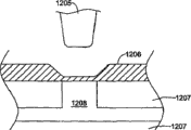
可提到图9c和9d的轴-膜界面。在该方法中,可用一端用弹性膜1206密封的圆筒形样品贮存室代替长和细的样品环。膜1206可位于塑壳(molded case)1207上,在样品贮存池1208上方。为了调配样品,用由微步电机旋转的丝杠推靠所述膜。这实质上可以是注射泵,使轴1205推靠膜1206而不是推进注射器筒内的活塞。该方法的优点是物理屏障膜1206可消除污染问题。Mention may be made of the axis-membrane interface of Figures 9c and 9d. In this method, the long and thin sample loop can be replaced by a cylindrical sample reservoir sealed at one end with an
方法可包括在卡安装在仪器中后找到轴1205的零位移(即只接触膜1206)。样品贮存室的体积改变反应可能与轴位移呈非线性关系,需要校准。轴1205尖端可针对位移效率设计。实际情况可以是,轴完全运作(at full stroke)可递送贮存室中80%样品。膜1206需要足够凹陷以便手指不会意外压到/驱动膜和调配样品。The method may include finding zero displacement of the shaft 1205 (ie only contacting the membrane 1206) after the card is installed in the instrument. The volume change response of the sample reservoir may be non-linear with axis displacement and requires calibration. The
膜-膜界面可如图9e和9f显示。在该方法中,可将样品仍贮存在一端用弹性膜密封的圆筒形贮存池内。可用具有膜1212封闭其尖端的驱动器1211引起膜1206位移。如果两膜1206和1212已经接触,将驱动液1213泵至驱动器1211尖端可使膜1212和1206都变形,移动样品池1208中的等体积流体。The membrane-membrane interface can be shown in Figures 9e and 9f. In this method, the sample can still be stored in a cylindrical reservoir sealed at one end with an elastic membrane. Displacement of the
该方法的一些优点可显而易见。流量传感器技术可用于控制驱动液1213的流速,最终控制样品流速。因为驱动是流体驱动的,所以膜1206和1212自然容易变形以提供高位移效率。该方法还可通过隔离血样于物理膜后消除污染问题。Some advantages of this approach may be apparent. Flow sensor technology can be used to control the flow rate of the
方法可包括在仪器中安装卡后找到零位移,以便使膜1212和1206恰好接触而不移动任何血样。样品贮存室1208的体积改变反应可能与驱动器膜1212的体积改变稍微偏离线性关系,需要校准。卡上的膜1206必须足够凹陷以便手指不会意外压到/驱动膜1206和调配样品。The method may include finding zero displacement after installing the card in the instrument so that the
图9e和9f的样品环不是狭长通道,而是浅的圆筒形腔室。膜1212与1206初始接触很好(即其间无空气截留),驱动液1213展开的体积可使膜偏斜可重复的量(可校准)。The sample loops of Figures 9e and 9f are not elongated channels but shallow cylindrical chambers.
在膜界面中可能有力度变化。弹性膜引入的顺应性应小,因为典型弹性体如硅酮橡胶和Neoprene的泊松比通常在0.45-0.50范围,几乎不可压缩。基本上,弹性体都可变形,但不可压缩;它们的形状容易改变但其体积不容易改变。因此,其中塑壳和驱动器的硬材料限制弹性体形状改变的膜-膜界面不应出现显著的来自弹性体低顺应性的动力学结果。There may be force variations in the membrane interface. The compliance introduced by the elastic membrane should be small, since typical elastomers such as silicone rubber and Neoprene usually have a Poisson's ratio in the range of 0.45-0.50 and are almost incompressible. Basically, elastomers are deformable but not compressible; they change shape easily but not their volume. Therefore, the membrane-membrane interface, where the hard materials of the plastic housing and the actuator limit the shape change of the elastomer, should not exhibit significant kinetic consequences from the low compliance of the elastomer.
膜1206的偏斜不能调配贮存室内容纳的所有样品或试剂。调配比例可用位移效率表征。ε=80%的效率应视为合理的。如果还假定膜偏斜与腔室直径的比率(例如,δ=1/3),则位移体积可以约为The deflection of the
Vdisp=εδ(π/4)d3 V disp =εδ(π/4)d 3
可如下估计贮存室的直径The diameter of the reservoir can be estimated as follows
d=((4Vdisp/(εδπ))1/3。d=((4V disp /(εδπ)) 1/3 .
图9g的表列出足够贮存样品推动流和每种试剂的贮存室直径,假定测定将进行4分钟,一半时间测量RBC,一半时间测量WBC。用于球化溶液和鞘溶液的卡上试剂贮存室的大小可基于足够大小的卡考虑。The table in Figure 9g lists the reservoir diameters sufficient to store the sample push flow and each reagent, assuming that the assay will be run for 4 minutes, half the time measuring RBC and half the time measuring WBC. The size of the on-card reagent reservoirs for the spheroidizing and sheathing solutions can be based on an adequately sized card.
用包含在仪器内的试剂贮存盒的针-隔界面供应试剂有显著优点。如果在仪器上提供小型的灭菌机械装置,则可通过膜-型界面或针-隔界面控制血样。There are significant advantages to supplying reagents from the needle-septum interface of a reagent storage cartridge contained within the instrument. Blood samples can be controlled through a membrane-type interface or a needle-septum interface if a small sterile mechanism is provided on the instrument.
图10是显示组装和操作样品分析仪的示例性方法示意流程图。在示例性实例中,可如351显示使用和分析血液分析盒,可如370所示使用和分析用控制盒以帮助验证分析仪的性能,和/或可如380所示使用和分析校准盒以帮助校准分析仪。每次都可安装血液分析盒进行血液分析。可如372所示将控制盒安装在分析仪,如374所示周期性运行如每天1次,以验证分析仪得到的是准确结果。如376所示,仪器可显示测量是否在范围内的标记。该标记可取决于测量是否在正常、低或高范围内。如380所示,可如382所示在校准盒上安装校准器并如384所示运行。仪器可如386所示调节符合校准的校准系数。可将校准卡安装在分析仪中,以低于控制卡的频率,如每3个月1次,以再校准分析仪。校准可包括操作前或操作后使精密珠流(precisionbead flow)通过流动通道,从而例如定标脉冲宽度,提供穿过通道的颗粒大小信息。Figure 10 is a schematic flow diagram showing an exemplary method of assembling and operating a sample analyzer. In an illustrative example, a blood analysis cartridge may be used and analyzed as shown at 351, a control cartridge may be used and analyzed as shown at 370 to help verify the performance of the analyzer, and/or a calibration cartridge may be used and analyzed as shown at 380 to Helps calibrate the analyzer. The blood analysis cartridge can be installed every time for blood analysis. A control box may be mounted on the analyzer as shown at 372 and run periodically as shown at 374 eg once a day to verify that the analyzer is getting accurate results. As indicated at 376, the instrument may display a flag indicating whether the measurement is within range. This flag can depend on whether the measurement is in the normal, low or high range. As shown at 380 , the calibrator may be mounted on the calibration box as shown at 382 and operated as shown at 384 . The instrument may adjust the calibration coefficients as indicated at 386 to match the calibration. A calibration card can be installed in the analyzer to recalibrate the analyzer at a lower frequency than the control card, eg, every 3 months. Calibration may include passing a precision bead flow through the flow channel before or after operation, eg, to calibrate the pulse width, to provide particle size information passing through the channel.
每个盒可容纳所有必需流体和/或成分以发挥相应功能。这样,不需要多少培训就可操作和/或维护分析仪,而且仍然获得准确结果。提供的具有活动式和/或一次性盒的样品分析仪可以由未经过专业培训的人员在实验室环境之外可靠地使用,可帮助使样品分析过程流线化,减少费用和医务人员负担,增加许多患者样品分析的方便性,包括需要相当频繁的血液监测/分析的患者。系统可指出试剂和/或样品流体是否腐坏、不新鲜、受污染、不正确或者不适当或不可接收。系统的最终活动可包括不进行分析、不提供结果、提供错误标记等。Each cartridge can hold all necessary fluids and/or components to function accordingly. This way, little training is required to operate and/or maintain the analyzer and still obtain accurate results. Offers sample analyzers with removable and/or disposable cartridges that can be reliably used by untrained personnel outside of a laboratory setting, helping to streamline the sample analysis process, reducing cost and medical staff burden, Increased ease of analysis of many patient samples, including those requiring fairly frequent blood monitoring/analysis. The system can indicate if reagents and/or sample fluids are spoiled, stale, contaminated, incorrect or inappropriate or unacceptable. The final activity of the system may include not performing an analysis, not providing a result, providing an error flag, etc.
当如351所示使用血液分析盒时,可将血样收集和放在血液分析盒内,如353和355显示。可根据需要通过毛细管作用或人工泵将血样吸入血液分析盒内。然后可将血液分析盒装在分析仪仪器中。在示例性实例中,然后分析仪可自行对准血液分析盒和分析仪的相应部分(如光源/光检测器等),如357显示。接着,可按压一个或多个按钮开始血液分析过程。在一些情况下,不按压按钮等,而是仅将盒装至分析仪中即可导致分析仪开始对准和血液分析过程。When a blood analysis cartridge is used as shown at 351, a blood sample may be collected and placed in the blood analysis cartridge, as shown at 353 and 355. The blood sample can be sucked into the blood analysis box by capillary action or manual pump as needed. The blood analysis cartridge can then be loaded into the analyzer instrument. In an illustrative example, the analyzer can then self-align the blood analysis cartridge and corresponding parts of the analyzer (eg, light source/light detector, etc.), as shown at 357 . Next, one or more buttons can be pressed to initiate the blood analysis process. In some cases, simply loading the cartridge into the analyzer without pressing a button or the like can cause the analyzer to begin the alignment and blood analysis process.
卡可如358运行。一旦驱动分析仪,分析仪就可进行多种测试。例如,分析仪可关闭血液分析卡上所有阀门,对卡上各种流体入口施加压力。然后分析仪可测量流过卡上一个或多个流量传感器的流速。流量应当为零,因为所有阀门都关闭。然而,如果流量传感器提示非零点流速,则分析仪可将流量传感器再校准回零点流量。这可帮助增加流量传感器测量的准确性。分析仪可检查和根据需要开始清除气泡。或者或另外,分析仪可检查活动式盒中血液的凝固,例如通过测量所施加压力之下的血样流速(如用流量传感器),如果流速相对于施加的压力而言太低,可判定血样已经凝固。如果发现血液凝固,分析仪可显示表明测量失败的消息。Cards can run as 358. Once the analyzer is driven, the analyzer can perform various tests. For example, the analyzer can close all valves on a blood analysis card and apply pressure to various fluid inlets on the card. The analyzer can then measure the flow rate through one or more flow sensors on the card. Flow should be zero since all valves are closed. However, if the flow sensor indicates a non-zero flow rate, the analyzer can recalibrate the flow sensor back to zero flow. This can help increase the accuracy of flow sensor measurements. The analyzer checks for and begins purging air bubbles as needed. Alternatively or additionally, the analyzer can check for coagulation of the blood in the removable cartridge, for example by measuring the flow rate of the blood sample under the applied pressure (e.g. with a flow sensor), and if the flow rate is too low relative to the applied pressure, it can be determined that the blood sample has solidification. If blood clotting is found, the analyzer can display a message indicating that the measurement failed.
然后分析仪可实施血液分析盒定时方案。血液分析盒定时方案可类似于2004年9月2日提交的美国专利申请序列号10/932,662显示和描述的方案,其转让给本发明受让人,通过引用结合到本文中。具体的血液分析盒定时方案可取决于血液分析盒的具体设计。分析仪还可验证血液分析盒上任何细胞计量通道中是否有稳定的核心流体,如果存在则鉴定核心流体的位置。The analyzer can then implement the blood analysis cartridge timing scheme. The blood analysis cartridge timing scheme may be similar to that shown and described in US Patent Application Serial No. 10/932,662, filed September 2, 2004, assigned to the assignee of the present invention, and incorporated herein by reference. The specific timing scheme of the blood analysis cartridge may depend on the specific design of the blood analysis cartridge. The analyzer also verifies the presence of stable core fluid in any cytometry channel on the blood analysis cartridge and, if present, identifies the location of the core fluid.
然后血液分析盒可以例如溶解将用于测量白细胞的血样部分的红细胞,使将用于测量红细胞的血样部分的红细胞球化,在血液分析盒上任何细胞计量通道内形成核心流体,和/或发挥任何其它所需功能。分析仪可将光提供至血液分析盒的所选区域如任何细胞计量通道,检测穿过所选区域的光。The blood analysis cartridge can then, for example, lyse the red blood cells in the portion of the blood sample that will be used to measure white blood cells, spheroidize the erythrocytes in the portion of the blood sample that will be used to measure red blood cells, form a core fluid within any cytometry channel on the blood analysis cartridge, and/or exert Any other desired functionality. The analyzer can provide light to selected areas of the blood analysis cartridge, such as any cytometry channel, and detect light passing through the selected areas.
这样,分析仪可对样品中的颗粒如白细胞、红细胞、血小板等进行计数和分类,然后显示、打印、发出声音或者为使用者标记血液分析结果。在一些实例中,分析仪显示或打印出定量结果(如在预定范围之内和/或之外),以便使用者不需要再计算或解释。可视为完成测量,如361所示,显示结果。最终,可取出分析仪的血液分析盒,如363所示弃置。In this way, the analyzer can count and classify the particles in the sample, such as white blood cells, red blood cells, platelets, etc., and then display, print, sound or mark the blood analysis results for the user. In some instances, the analyzer displays or prints quantitative results (eg, within and/or outside predetermined ranges) so that no further calculations or interpretations are required by the user. The measurement can be considered complete, as shown at 361, and the result is displayed. Finally, the analyzer's blood analysis cartridge can be removed and disposed of as shown at 363 .
当将如370显示进行控制运行时,可使用控制盒。在一些情况下,可定期进行控制运行,如每天1次或每周1次。控制盒可包括具有已知特征的控制样品。因此,当用分析仪对控制样品进行分析时,应获得已知结果。在示例性方法中,将控制盒装在分析仪内,如372显示。接着,启动分析仪,如374显示,分析仪进行分析和显示结果,如376显示。在一些实例中,分析仪显示或打印出定量结果(如在预定范围之内和/或之外),以便使用者不需要再计算或解释。最终,可取出分析仪的控制盒并弃置。如果控制运行的结果在预定范围之外,可优选进行校准运行,如校准运行380。When the control operation is to be performed as shown in 370, a control box can be used. In some cases, control runs may be performed on a regular basis, such as once a day or once a week. A control box may contain a control sample with known characteristics. Therefore, when the control samples are analyzed by the analyzer, known results should be obtained. In an exemplary method, a control box is housed within the analyzer, as shown at 372 . Next, the analyzer is started, as shown in 374 , and the analyzer performs analysis and displays the results, as shown in 376 . In some instances, the analyzer displays or prints quantitative results (eg, within and/or outside predetermined ranges) so that no further calculations or interpretations are required by the user. Finally, the analyzer's control box can be removed and disposed of. If the results of the control run are outside a predetermined range, a calibration run, such as calibration run 380, may preferably be performed.
当将进行380显示的校准运行时,可使用校准盒。在一些情况下,可定期进行校准运行,如每月1次,或者根据需要。校准盒可包括具有已知特征的校准样品。因此,当用分析仪对校准样品进行分析时,应得到已知结果。在示例性方法中,将校准盒装在分析仪内,如382显示。接着,启动分析仪,如384显示,得到多个结果。通过比较预期结果与校准运行时得到的结果,分析仪可自动调节存储器中的一个或多个校准因子以再校准分析仪,以便在下一次运行时,分析仪将产生预期或所需结果,如386显示。The calibration box may be used when a calibration run of the 380 display is to be performed. In some cases, calibration runs may be performed periodically, such as once a month, or as needed. Calibration cartridges may include calibration samples with known characteristics. Therefore, when the calibration samples are analyzed by the analyzer, known results should be obtained. In an exemplary method, a calibration cartridge is loaded into the analyzer, as shown at 382 . Next, the analyzer is started, as shown at 384, and multiple results are obtained. By comparing the expected results with those obtained during the calibration run, the analyzer can automatically adjust one or more calibration factors in memory to recalibrate the analyzer so that on the next run, the analyzer will produce the expected or desired results, e.g. 386 show.
图11a是显示操作样品分析仪示例性方法的流程图。示例性方法总体如400显示,在步骤402进入。控制到达步骤404,其中将血样提供至一次性流体盒内。然后控制到达步骤406,其中将一次性流体盒插入血样分析仪内。然后控制到达步骤408。步骤408启动血样分析仪,步骤410从血样分析仪得到血液分析结果,而不再需要血样分析仪使用者的任何相互作用。然后控制到达步骤412,退出步骤。Figure 11a is a flowchart showing an exemplary method of operating a sample analyzer. The exemplary method is generally shown at 400 and entered at
图11b是显示另一种操作样品分析仪的示例性方法流程图。示例性方法总体如500显示,在步骤502开始。控制到达步骤504,其中将血样提供至一次性流体盒。然后控制到达步骤506,其中将一次性流体盒插入血样分析仪内。然后控制到达步骤508。步骤508启动血样分析仪,步骤510从血样分析仪得到血液分析结果,而不再需要血样分析仪使用者的任何相互作用。然后控制到达步骤512。步骤512确定血液分析结果是否在预定范围内。如上所述,在一些实例中,分析仪可显示或打印出定量结果(如在预定范围之内和/或之外),以便使用者不需要再计算或解释。然后控制到达步骤514,退出步骤。11b is a flowchart showing another exemplary method of operating a sample analyzer. The exemplary method is shown generally at 500 and begins at
图12是显示操作样品分析仪的另一种示例性方法流程图。方法总体如600显示,在步骤602进入。在示例性方法中,可如604所示使用和分析血液分析盒,可如620所示使用并分析控制盒以帮助验证分析仪的性能,和/或可如640所示使用并分析校准盒以帮助校准分析仪。可在每次进行血液分析时安装血液分析盒。可将控制盒定期如每天1次装在分析仪中,以验证分析仪可产生准确结果。可以更低频率如每3个月1次将校准盒装在分析仪中,以再校准分析仪,或者根据需要校准。Figure 12 is a flowchart showing another exemplary method of operating a sample analyzer. The method is generally shown at 600 and entered at
每种盒类型都可包含所有必需的流体和/或发挥相应功能的成分。这样,可以不需要很多培训就可操作和/或维护分析仪,获得准确结果。提供的具有活动式和/或一次性盒的样品分析仪可以经过很少或不经过专业培训就可在实验室环境之外可靠地使用,可帮助使样品分析过程流线化,减少费用和医务人员负担,增加许多患者样品分析的方便性,包括需要相当频繁的血液监测/分析的患者。Each cartridge type can contain all necessary fluids and/or components to function accordingly. This way, the analyzer can be operated and/or maintained without extensive training to obtain accurate results. Offers sample analyzers with removable and/or disposable cartridges that can be used reliably outside of a laboratory setting with little or no specialized training, helping to streamline the sample analysis process, reducing cost and medical Staff burden, increasing convenience for sample analysis of many patients, including patients requiring fairly frequent blood monitoring/analysis.
在图12的示例性方法中,当使用血液分析盒时,控制到达步骤604。在步骤606中,将血样提供至一次性流体盒。然后控制到达步骤608,其中将一次性流体盒插入血样分析仪内。然后控制到达步骤610。步骤610启动血样分析仪,步骤612从血样分析仪得到分析结果。In the exemplary method of FIG. 12 , control passes to step 604 when a blood analysis cartridge is used. In
当使用控制盒时,控制到达步骤620。步骤620使控制到达步骤622,其中将控制盒插入血样分析仪内。然后控制到达步骤624。步骤624启动血样分析仪,步骤626用控制流体盒得到控制分析结果。然后控制到达步骤628。步骤628确定控制分析结果是否在预期控制范围内。如果控制分析结果不在预期范围内,不应相信血液分析盒得到的结果。在一些情况下,可用校准盒再校准样品分析仪,然后用另一个控制盒验证样品分析仪的操作/校准。Control passes to step 620 when a control box is used. Step 620 passes control to step 622, where the control cartridge is inserted into the blood sample analyzer. Control then passes to step 624 . Step 624 starts the blood sample analyzer, and step 626 uses the control fluid cartridge to obtain control analysis results. Control then passes to step 628. Step 628 determines whether the control analysis results are within expected control limits. If the control assay results are not within the expected range, the results obtained by the blood analysis cartridge should not be trusted. In some cases, the sample analyzer can be recalibrated with a calibration cartridge, and then another control cartridge can be used to verify the operation/calibration of the sample analyzer.
当使用校准盒时,控制到达步骤640。步骤640使控制到达步骤642。步骤642将校准盒插入血样分析仪内。然后控制到达步骤644。步骤644启动血样分析仪,步骤646用校准流体盒得到校准分析结果。然后控制到达步骤648。根据校准分析结果,步骤648根据需要调节分析仪。Control passes to step 640 when a calibration cartridge is used. Step 640 passes control to step 642 . Step 642 inserts the calibration cartridge into the blood sample analyzer. Control then passes to step 644 . Step 644 starts the blood sample analyzer, and step 646 uses the calibration fluid cartridge to obtain calibration analysis results. Control then passes to step 648. Based on the results of the calibration analysis,
在一些情况下,样品分析仪可以是完全自动化的仪器、一体式和/或自持的测试仪器。样品分析仪可接收和分析直接未处理的样本如毛细血管血(刺手指)、静脉全血、鼻拭子或尿液等。或者或另外,样品分析仪可只需要基本的非技术依赖性样本操作,包括任何去污染操作。同样,样品分析仪可只需要基本的非技术依赖性试剂操作,如“混合试剂A和试剂B”,在分析步骤时可不需要操作者干预。在一些情况下,样品分析仪可包括或提供说明书(在一些情况下,当确认测试在临床上适当时,样品分析仪可包括或提供获得和运输用于确认测试的样本所用的材料)。In some cases, the sample analyzer can be a fully automated instrument, an all-in-one and/or self-contained test instrument. The sample analyzer accepts and analyzes directly unprocessed samples such as capillary blood (finger prick), venous whole blood, nasal swabs or urine. Alternatively or additionally, the sample analyzer may require only basic non-technology dependent sample operations, including any decontamination operations. Likewise, the sample analyzer may only require basic non-technology-dependent reagent operations, such as "mixing reagent A and reagent B", and may not require operator intervention during the analysis step. In some cases, the sample analyzer may include or provide instructions (and in some cases, when the confirmatory test is clinically appropriate, the sample analyzer may include or provide materials for obtaining and shipping a sample for the confirmatory test).
样品分析仪可配备快速参考说明书指南。快速参考指南可提供操作样品分析仪的快速参考。使用时,使用者在对如何操作样品分析仪有任何问题时可参考快速参考指南。Sample analyzers can be supplied with a Quick Reference Instructions Guide. The Quick Reference Guide provides a quick reference for operating the sample analyzer. In use, the user can refer to the Quick Reference Guide if they have any questions about how to operate the sample analyzer.
在一些情况下,快速参考指南可包括自解图像或图表,图解举例说明各种操作步骤,有时由样品收集开始直至分析进行说明。在一个示例性实例中,快速参考指南只包括图像或图表,不包括词语或包括最小量词语。这可帮助不精通具体语言(如英语)的使用者有效地操作样品分析仪。在一个示例性实例中,快速参考指南可显示和/或描述步骤:从包装内取出一次性盒;取下盒刺血针的充血帽和/或取下标记物的盖(如带),该标记物在暴露于空气一段预定时间后变色;抽取患者血液;将抽取的血液提供至盒;将盒装在仪器中;运行仪器和接收结果;从仪器取出盒,弃置盒。这只是一个实例。In some cases, quick reference guides may include self-explanatory images or diagrams that illustrate various steps, sometimes from sample collection through analysis. In one illustrative example, the quick reference guide includes only images or diagrams and no words or a minimal number of words. This helps users who are not fluent in a specific language, such as English, to operate the sample analyzer effectively. In one illustrative example, the quick reference guide may show and/or describe the steps of: removing the disposable cartridge from the package; The marker changes color after being exposed to air for a predetermined period of time; blood is drawn from the patient; the drawn blood is provided to the cartridge; the cartridge is installed in the instrument; the instrument is run and results are received; the cartridge is removed from the instrument and the cartridge is discarded. This is just an example.
预期仪器外壳可包括放置快速参考指南的口袋等。使用时,使用者可翻开口袋的快速参考指南进行参考。或者,可用螺旋状夹子等将快速参考指南固定在样品分析仪外壳,这可允许使用者在使用时翻动快速参考指南各页。在另一个示例性实例中,可将快速参考指南固定在活动式盒上,或者可打印在装活动式盒的包装上。在还有另一个示例性实例中,可将快速参考指南打印在传单上,可将传单贴在靠近样品分析仪的墙壁等上。It is contemplated that the instrument housing may include pockets for quick reference guides and the like. When in use, the user can flip open the quick reference guide in the pocket for reference. Alternatively, the quick reference guide may be secured to the sample analyzer housing with a screw-type clip or the like, which may allow the user to flip through the pages of the quick reference guide during use. In another illustrative example, the quick reference guide may be affixed to the removable cartridge, or may be printed on the packaging containing the removable cartridge. In yet another illustrative example, the quick reference guide can be printed on a leaflet that can be affixed to a wall or the like near the sample analyzer.
在一些情况下,为了进一步减少产生错误结果的危险,可提供一种或多种故障报警和/或故障安全机械装置。例如,在一个示例性实例中,样品分析仪可帮助检测使用者是否提供错误的样本类型。例如,如果设定样品分析仪进行全血样品的白细胞计数,则样品分析仪可帮助检测使用者提供的样本是否不是血液。In some cases, to further reduce the risk of erroneous results, one or more fail-alarm and/or fail-safe mechanisms may be provided. For example, in one illustrative example, a sample analyzer can help detect if a user is providing the wrong sample type. For example, if the sample analyzer is set to perform a white blood cell count on a whole blood sample, the sample analyzer can help detect whether the sample provided by the user is not blood.
在一个示例性实例中,样品分析仪可进行分析,如果一种或多种输出参数在预定范围外,则样品分析仪可能不提供结果和/或发出错误消息或错码。例如,如果样品分析仪是用于对全血样品进行白细胞计数的流式细胞仪,样品分析仪未对任何白细胞(或小量白细胞)计数,则样品分析仪可能不提供结果,在一些情况下,提供错误消息或错码。In one illustrative example, the sample analyzer may perform an analysis, and if one or more output parameters are outside a predetermined range, the sample analyzer may not provide a result and/or issue an error message or error code. For example, if the sample analyzer is a flow cytometer used to count white blood cells on a whole blood sample, and the sample analyzer does not count any white blood cells (or a small number of white blood cells), the sample analyzer may not provide results, in some cases , providing an error message or error code.
在一些实例中,一种或多种光学测量可用于帮助鉴定流动通道中是否存在不正确的流体,如当使用者提供不正确的样本时,或者当没有将试剂提供至流体盒的正确流动通道时。图13显示一种此类光学测量。在图13中,样品流体700存在于由例如流体盒的通道壁704限定的通道702内。在示例性实例中,通道壁704具有折射率“nw”,样品流体具有折射率“ns”。光源706提供与通道壁704之一成角的入射光束(有时是准直光束)。放置的检测器708用于检测从通道壁/样品界面反射的光710。从通道/样品界面反射至检测器708的光的量将取决于通道壁“nw”和样品流体“ns”的相对折射率。当所需样品流体700存在于通道702中时,可确定所需反射量或反射信号。当将不正确的样本类型或不正确的试剂或其它不正确的样品流体提供至流动通道700时,不正确样品流体的“nic”折射率可导致检测器708测量到光710的不同反射信号。此类改变可表明流动通道702中存在不正确的样品流体。或者或另外,此类改变可表明存在气泡、血块或其它不需要的颗粒或样品流体的其它特征。当如此检测时,样品分析仪可能不提供结果,在一些情况下,可能向使用者发出错误消息或错码。In some instances, one or more optical measurements can be used to help identify the presence of incorrect fluid in a flow channel, such as when a user provides an incorrect sample, or when reagents are not provided to the correct flow channel of a fluid cartridge hour. Figure 13 shows one such optical measurement. In Fig. 13, a
图14显示另一种可用于帮助鉴定流动通道中何时存在不正确或不需要的流体的光学测量。在图14中,样品流体720存在于例如流体盒的通道壁724限定的流动通道722内。在示例性实例中,通道壁724具有折射率“nw”,样品流体具有折射率“ns”。光源726提供与通道壁724之一成角的入射光束(有时是准直光束)。放置的检测器728用于检测穿过通道722和样品流体720的光730。Figure 14 shows another optical measurement that can be used to help identify when incorrect or unwanted fluid is present in a flow channel. In Figure 14, a
在该示例性实例中,使通道722足够细,以便当样品流体折射率“ns”在所需范围内时允许光学隧穿(optical tunneling)穿过通道722和样品流体720。如果样品流体折射率“ns”低于所需范围,则光将不穿过通道722,而是被反射。如果样品流体折射率“ns”高于所需范围,则光将倾向于穿过通道722和样品流体720,因此该实例可能最适合用于检测折射率“ns”小于所需样品(如血液)的折射率的不正确样品流体。或者或另外,该示例性实例可根据需要用于检测气泡、血块或其它不需要的颗粒或者样品流体其它特征的存在。当这样检测时,样品分析仪可能不提供结果,在一些情况下,可能提供错误消息或错码。In this illustrative example,
图15是另一种可用于鉴定例如流体盒的流动通道中何时存在不正确或不需要的流体的示例性实例。在该示例性实例中,将样品流体750提供在由通道壁754限定的流动通道752中。在示例性实例中,将两个或多个电极760提供在一个或多个通道壁754上,在一些实例中,可在一个或多个塑料片上形成两个或多个电极760,其呈层叠状或者固定一起形成流体盒的流体回路。可将两个或多个电极组装延伸入流体盒上的流动通道752内或沿着流体盒上的流动通道752延伸,与所需驱动电路连接。FIG. 15 is another illustrative example that may be used to identify when incorrect or unwanted fluid is present, for example, in a flow channel of a fluid cartridge. In this illustrative example,
电源758可在电极760之间提供信号,可测量通过样品流体750的电极之间的电阻。这可测量通道752中样品流体750的电阻率。当不正确的样品流体出现在流动通道752时,不正确样品流体的电阻率可在预期范围之外。电阻率超出预期范围可还提示存在气泡、血块或其它不需要的颗粒或者样品流体的其它特征。当这样检测时,样品分析仪可不提供结果,在一些情况下,可能提供错误消息或错码。The
在一些情况下,电源758可提供低电位AC信号(如小于10V峰-峰、小于5V峰-峰、小于3V峰-峰、小于1V峰-峰、小于0.5V峰-峰或小于0.1V峰-峰),以限制电极760导致样品流体750的电化学反应。电化学反应可以例如将气泡等引入样品流体750中,在一些情况下这可能不希望出现。In some cases,
除了使用上文描述的电阻率测量之外或取而代之的是,预期可使用电容测量。在该示例性实例中,可通过样品750测量两个或多个电极之间的电容。当将不正确的样品流体提供至流动通道752时,不正确样品流体的电容结果可能超出预期范围。电容超出预期范围还可提示存在气泡、血块或其它不需要的颗粒或者样品流体的其它特征。当这样检测时,样品分析仪可能不提供结果,在一些情况下,可能提供错误消息或错码。In addition to or instead of using resistivity measurements described above, it is contemplated that capacitance measurements may be used. In this illustrative example, capacitance between two or more electrodes may be measured through
图16是另一种可用于鉴定例如流体盒的流动通道中何时存在不正确或不需要的流体的示例性实例。在该示例性实例中,将样品流体770提供在由通道壁774限定的流动通道772中。在示例性实例中,提供PH传感器776与样品流体770流体相通。PH传感器776可检测样品流体770的PH,将信号报告至控制器780。当将不正确的样品流体提供至流动通道772时,不正确样品流体的PH可超出预期范围。PH水平超出预期范围还可提示存在气泡、血块或其它不需要的颗粒或者样品770的其它特征。当这样检测时,样品分析仪可不提供结果,在一些情况下,可能提供错误消息或错码。FIG. 16 is another illustrative example that may be used to identify when incorrect or unwanted fluid is present in, for example, a flow channel of a fluid cartridge. In this illustrative example,
图17是可用于鉴定流动通道中样品流体何时出现一个或多个气泡或者其它不需要的颗粒的示例性实例。在该示例性实例中,样品流体800存在于由例如流体盒的通道壁804限定的流动通道802中。光源806提供与通道壁804之一成角的入射光束(有时为准直光束)。放置的检测器808用于检测被流动通道802中样品流体800内存在的气泡或其它不需要的颗粒散射的光730。如果,例如样品流体800没有任何气泡,则光将无散射地穿过样品流体,检测器808将检测不到信号(或低信号)。当检测器808发现高于某一阈值的光散射信号时,表明流动通道802中的样品流体800具有一个或多个气泡或其它不需要的颗粒,样品分析仪可能不提供结果,在一些情况下,可能提供错误消息或错码。17 is an illustrative example that can be used to identify when one or more air bubbles or other unwanted particles are present in a sample fluid in a flow channel. In this illustrative example,
图18是可用于鉴定流动通道中的样品流体何时出现一个或多个气泡或者其它不需要的颗粒的示例性实例。在该示例性实例中,样品流体820存在于由例如流体盒的通道壁824限定的流动通道822中。提供超声换能器826和超声接收器828邻近流动通道822。在一些情况下,提供的超声换能器826位于流动通道822一侧,提供的超声接收器828位于对侧。在其它情况下,提供的超声换能器826和超声接收器828位于流动通道822同侧。在任何一种情况下,超声接收器828都可用于检测由流体样品820中的气泡或其它不需要的颗粒引起超声换能器826发出的超声信号的散射。当这样检测时,样品分析仪可能不提供结果,在一些情况下,可能提供错误消息或错码。FIG. 18 is an illustrative example that may be used to identify when one or more air bubbles or other unwanted particles are present in a sample fluid in a flow channel. In this illustrative example,
图19是另一种可用于鉴定流动通道中的样品流体何时出现一个或多个气泡或者其它不需要的特征的示例性实例。在该示例性实例中,样品流体850位于由例如流体盒的通道壁854限定的流动通道852内。提供的流量传感器856与流动通道852流体相通,用于检测样品流体850的流速。流量传感器可以是例如热气流速型流量传感器和/或微桥型流量传感器。微桥流量传感器描述于例如,美国专利号4,478,076、美国专利号4,478,077、美国专利号4,501,144、美国专利号4,651,564、美国专利号4,683,159和美国专利号5,050,429,全部通过引用结合到本文中。FIG. 19 is another illustrative example that may be used to identify when one or more air bubbles or other unwanted characteristics are present in a sample fluid in a flow channel. In this illustrative example, sample fluid 850 is located within flow channel 852 defined, for example, by channel wall 854 of the fluid cartridge. A flow sensor 856 is provided in fluid communication with the flow channel 852 for sensing the flow rate of the sample fluid 850 . The flow sensor may be, for example, a flow sensor of the hot gas velocity type and/or a flow sensor of the microbridge type. Microbridge flow sensors are described, for example, in US Patent No. 4,478,076, US Patent No. 4,478,077, US Patent No. 4,501,144, US Patent No. 4,651,564, US Patent No. 4,683,159, and US Patent No. 5,050,429, all of which are incorporated herein by reference.
压力源860可将可变压力提供给流动通道852中的样品流体850。控制器862可接收来自流量传感器856的流速信号,在一些情况下,可控制压力源860。在一个示例性实例中,为了检测样品流体的气泡,控制器862可导致压力源860突然改变施加在样品流体850的压力。然后可用流量传感器856监测样品流体850所产生的流速改变。Pressure source 860 may provide variable pressure to sample fluid 850 in flow channel 852 . Controller 862 may receive a flow rate signal from flow sensor 856 and, in some cases, may control pressure source 860 . In one illustrative example, to detect air bubbles in the sample fluid, controller 862 may cause pressure source 860 to suddenly change the pressure applied to sample fluid 850 . The resulting change in flow rate of sample fluid 850 can then be monitored with flow sensor 856 .
图20是显示可由压力源860提供至图19流动通道852内样品流体850的示例性压力脉冲900的图。样品流体850中很少或没有气泡时,可得到902显示的流速。当压力脉冲900突然增加时,流速902更迅速地从较低流速值904增加至较高流速值906,当压力脉冲900突然降低时,则迅速从较高流速值906降低至较低流速值904。然而,当样品流体850出现气泡时,当压力脉冲900突然增加,所得流速908(虚线显示)可能更缓和地从较低流速值904增加至较高流速值906,当压力脉冲900突然降低,所得流速908可能更缓和地从较高流速值906降低至较低流速值904。气泡内的空气可以例如增加样品流体850的压缩性,所以导致流速更缓和地增加和降低。通过监测施加压力改变时流速的改变,可发现样品流体850中存在气泡。如果发现流速改变充分减少,样品分析仪可能不提供结果,在一些情况下,可能提供错误消息或错码。FIG. 20 is a graph showing
预期压力源860可以是合适的压力源,包括常规泵、压缩空气源或需要的任何其它合适压力源。在一些情况下,压力源860可以是高频压力源如压电振动器、超声换能器或任何其它类型高频压力源。在一些情况下,高频压力源可与常规泵或其它压力源联合使用,可以并行操作。也就是说,在分析样品流体时,常规泵或其它压力源860可用于使样品流体实际移动通过流体盒的流动通道852。高频压力源不可以用于使样品流体沿流动通道明显移动,但可用于对样品流体产生高频压力脉冲以检测样品流体的某些参数,包括例如气泡的存在、样品流体的压缩性等。样品流体的压缩性可用于帮助确定流动通道852中的样品流体850是否是预期样品流体类型,如果不是,则样品分析仪可能不提供结果,在一些情况下,可能提供错误消息或错码。The desired pressure source 860 may be a suitable pressure source, including a conventional pump, a compressed air source, or any other suitable pressure source as desired. In some cases, pressure source 860 may be a high frequency pressure source such as a piezoelectric vibrator, an ultrasonic transducer, or any other type of high frequency pressure source. In some cases, high frequency pressure sources can be used in conjunction with conventional pumps or other pressure sources, allowing parallel operation. That is, when analyzing a sample fluid, a conventional pump or other pressure source 860 may be used to actually move the sample fluid through the flow channel 852 of the fluid cartridge. A high frequency pressure source may not be used to move the sample fluid appreciably along the flow channel, but may be used to generate high frequency pressure pulses on the sample fluid to detect certain parameters of the sample fluid including, for example, the presence of air bubbles, the compressibility of the sample fluid, and the like. The compressibility of the sample fluid can be used to help determine if the sample fluid 850 in the flow channel 852 is the expected sample fluid type, if not the sample analyzer may not provide a result, and in some cases, may provide an error message or code.
在任何事件中,在一些情况下,当高频压力源与常规泵或其它压力源同时或并行运行时,可在流体回路处理样品时原位监测样品流体。In any event, in some cases, when the high frequency pressure source is run simultaneously or in parallel with a conventional pump or other pressure source, the sample fluid can be monitored in situ while the fluid circuit is processing the sample.
在一些情况下,压力脉冲可用于确定或估计流体回路的流动通道中样品流体末端或远端的位置。图21显示一种此类示例性实例。在图21中,显示两个流动通道1000和1002。样品流体1004存在于流动通道1000中,样品流体1006存在于流动通道1002中。显示压力换能器(如压力源)1008和压力接收器(如压力传感器)1010在相对于流动通道1000的已知位置与样品流体1004流动连接。压力换能器1008可在样品流体1004中产生压力脉冲。压力脉冲沿样品流体1004传播至末端1012。压力脉冲的一些能量将被样品流体1004的末端1012反射回压力接收器1010。末端1012当前的位置与压力换能器1008和/或压力接收器1010的距离与压力脉冲沿样品流体1004传播至末端1012并返回压力接收器1010需要的时间相关。因此,通过测量压力脉冲传播至末端1012并返回压力接收器1010需要的时间,可测定末端1012沿流动通道1000的位置。In some cases, the pressure pulses can be used to determine or estimate the position of the sample fluid end or distal end in the flow channel of the fluid circuit. Figure 21 shows one such illustrative example. In Fig. 21, two
流动通道1002类似于流动通道1000,但末端位于沿流动通道更远的距离。因此,假定样品流体1006与样品流体1004相同,压力脉冲传播至末端1014并返回压力接收器1018需要的时间将大于流动通道1000需要的时间。而且,压力接收器1018接收的反射压力脉冲的振幅可能比压力接收器1010接收的压力脉冲的振幅弱。因此,监测振幅可提供另一种分别估计或确定末端1012和1014沿着流动通道1000和1002的位置。
图22-23显示确定两种流体何时在流体回路汇集的示例性方法。在许多样品分析仪中,最初是将不同流体提供在不同的流动通道。然而,在流体回路中,各种流体通常混合。例如,虽然最初可以将血样和球化剂提供在单独的流动通道中,但接着在流体回路下游某处混合一起。各种流体何时和如何集中可能对样品分析仪的整体功能很重要,如美国专利申请序列号10/932,662所公开,其转让给本发明受让人,通过引用结合到本文中。22-23 illustrate exemplary methods of determining when two fluids have joined in a fluid circuit. In many sample analyzers, different fluids are initially provided in different flow channels. However, in a fluid circuit, the various fluids are often mixed. For example, although the blood sample and spheroidizing agent may initially be provided in separate flow channels, they are then mixed together somewhere downstream in the fluid circuit. When and how the various fluids are concentrated can be important to the overall function of the sample analyzer as disclosed in US Patent Application Serial No. 10/932,662, assigned to the assignee of the present invention and incorporated herein by reference.
为了帮助确定两种或多种流体何时在流体回路下游汇集,可用压力换能器在至少一种流体样品中产生压力脉冲。例如,参考图22,压力换能器1030(如泵、压电振动器、超声换能器或任何其它类型压力换能器)可在第一流动通道1034中的样品流体1032中产生压力脉冲。压力接收器1036(如压力传感器、超声接收器等)可与第二流动通道1042的样品流体1040流体相通。第一流动通道1034和第二流动通道1042可集中在流动通道1044,最好如图23显示。To help determine when two or more fluids have converged downstream of the fluid circuit, a pressure transducer may be used to generate a pressure pulse in at least one of the fluid samples. For example, referring to FIG. 22 , a
再参考图22,由压力换能器1030在第一种样品流体1032中产生的压力脉冲可沿第一种样品流体1032传播,但可能不明显延伸至第一种样品流体1032的末端或远端1046。在示例性实例中,最初用空气或其它气体填充图22显示的流动通道1044,然后当样品流体1032和1040被沿其各自的流动通道1034和1042推动时被样品流体1032和1040代替。在样品流体1032和1040集中之前,压力接收器1036不可能接收来自压力换能器1030的显著的压力脉冲或者明显衰减的压力脉冲。Referring again to FIG. 22 , the pressure pulse generated in the
可启动一个或多个压力源(未显示)如泵等,使样品流体1032和1040沿其各自的流动通道1034和1042移动,直至样品流体1032和1040汇集,如图23更好的显示。当出现这种情况时,压力换能器1030产生的压力脉冲现在可以更自由地传播至压力接收器1036。因此,通过监测压力接收器1036何时开始接收或者接收到来自压力换能器1030的较少衰减的压力脉冲,可确定样品流体1032和1040何时汇集。One or more pressure sources (not shown), such as pumps, etc., can be activated to move the
在一些情况下,压力换能器1030可在样品流体中产生压力脉冲序列(有时相当高频率),可与实际使样品流体1032和1040沿流体回路的流动通道1034、1042和1044移动的泵或其它压力源同时或并行操作。因此,压力换能器1030可用于原位监测流体回路的样品流体,更具体来讲监测样品流体1032和1040何时在下游汇集。In some cases,
在一些情况下,当分析时样品分析仪未处于水平面,可影响样品分析仪的运行。为了检测这种情况,预期样品分析仪可包括水平传感器。在一个示例性实例中,水平传感器可以是购自Omron Corporation的Micro Tilt传感器(D6B)。其它水平传感器可包括具有电输出的球传感器。使用水平传感器,样品分析仪可确定样品分析仪是否足够水平以进行分析。如果样品分析仪不够水平,则样品分析仪可能不进行分析和/或不提供结果,在一些情况下,可能提供错误消息或错码。In some cases, the sample analyzer is not on a horizontal plane when analyzing, which can affect the operation of the sample analyzer. To detect this condition, it is contemplated that the sample analyzer may include a level sensor. In an illustrative example, the level sensor can be a Micro Tilt sensor (D6B) available from Omron Corporation. Other level sensors may include ball sensors with electrical outputs. Using the level sensor, the sample analyzer can determine if the sample analyzer is level enough for analysis. If the sample analyzer is not level enough, the sample analyzer may not perform the analysis and/or provide no results, and in some cases, may provide an error message or wrong code.
另一种检查样品分析仪是否足够水平的方法包括使容纳流体的一条或多条流动通道降压,测量流体在一条或多条流动通道中的流速。如果样品分析仪不够水平,重力可导致一条或多条流动通道的流速超出预期范围。如果流速超出预期范围,可将样品分析仪视为不够水平,样品分析仪可能不进行分析和/或不提供结果,在一些情况下,可能提供错误消息或错码。Another method of checking the adequacy of the sample analyzer involves depressurizing one or more flow channels containing the fluid and measuring the flow rate of the fluid in the one or more flow channels. If the sample analyzer is not level enough, gravity can cause the flow rate in one or more flow channels to exceed the expected range. If the flow rate is outside the expected range, the sample analyzer may be considered insufficient and the sample analyzer may not analyze and/or provide no results, and in some cases, error messages or codes.
在一些情况下,分析时碰撞或移动样品分析仪可能影响样品分析仪运行。为了发现这种情况,预期样品分析仪可包括震动和/或摆动传感器。在一个示例性实例中,震动和/或摆动传感器可以是购自OmronCorporation的Shock/Vibration传感器(D7E-2)。使用震动和/或摆动传感器,样品分析仪可确定样品分析仪是否被碰撞或移动。如果样品分析仪已被充分碰撞,则样品分析仪可能需要使用者在开始之前运行控制卡或校准卡,以验证样品分析仪正确运行。在一些情况下,样品分析仪可确定分析时样品分析仪是否被碰撞或移动。如果在分析时样品分析仪已被充分碰撞,则样品分析仪可能不提供结果,在一些情况下,可能提供错误消息或错码。In some cases, bumping or moving the sample analyzer during analysis may affect sample analyzer operation. To detect this, it is contemplated that the sample analyzer may include shock and/or vibration sensors. In one illustrative example, the shock and/or vibration sensor may be a Shock/Vibration sensor (D7E-2) available from Omron Corporation. Using shock and/or vibration sensors, the sample analyzer can determine if the sample analyzer has been bumped or moved. If the sample analyzer has been jolted sufficiently, the sample analyzer may require the user to run a control or calibration card before starting to verify that the sample analyzer is functioning correctly. In some cases, the sample analyzer may determine if the sample analyzer was bumped or moved during analysis. If the sample analyzer has been sufficiently bumped while analyzing, the sample analyzer may not provide a result and, in some cases, may provide an error message or wrong code.
在一些情况下,样品分析仪可包括仪器和活动式和/或一次性盒。因为使用者的行为有时不可预期,所以可能需要在开始分析之前确认将盒正确插入仪器内。一种实施方法是将盒和仪器设计成只有方向正确才可将盒插入仪器内。例如,图24显示由仪器1102的槽缝接收(箭头1104)的盒1100。示例性盒1100包括位于盒1100上表面的凹槽1106。仪器包括相应的凸件1108,当以相对于仪器1102方向正确地插入盒1100时,该凸件适合延伸入凹槽1106中。如果上下颠倒插入盒1100,则凹槽1106和凸件1108将不对口,将防止盒1100完全插入仪器1102的槽缝内。同样,如果盒1100的一端1112插入仪器1102的槽缝内,则凹槽1106和凸件1108将不对口,将防止盒1100完全插入仪器1102的槽缝内。这只是将盒1100锁定仪器1102以便盒1100只能以正确的方向插入仪器1102内的一种实例。In some cases, a sample analyzer can include an instrument and removable and/or disposable cartridges. Because user behavior is sometimes unpredictable, it may be necessary to confirm that the cartridge is correctly inserted into the instrument before starting an analysis. One method of implementation is to design the cartridge and instrument so that the cartridge can only be inserted into the instrument in the correct orientation. For example, FIG. 24
可通过任何方法确认盒相对于仪器的方向,特别是如果盒没有锁定相关仪器时。例如,在一些实例中,当盒正确地插入仪器时,一个或多个压力口可在仪器与盒之间延伸。仪器可对一个或多个压力口施加压力,检查是否发现所需流体。如果仪器压力口与盒压力口不对接,则不可发现所需流体。如果没发现所需流速,则样品分析仪可能不进行分析和/或不提供结果,在一些情况下,可能提供错误消息或错码。The orientation of the cartridge relative to the instrument can be confirmed by any means, especially if the cartridge is not locked to the associated instrument. For example, in some instances, one or more pressure ports may extend between the instrument and the cartridge when the cartridge is properly inserted into the instrument. The instrument applies pressure to one or more pressure ports and checks to see if the desired fluid is found. If the instrument pressure port does not interface with the cartridge pressure port, the desired fluid may not be found. If the desired flow rate is not found, the sample analyzer may not perform an analysis and/or provide no results, and in some cases, an error message or error code.
在另一个实例中,盒可包括一个或多个光学窗口或其它光学结构。如果将盒正确地装入仪器中,仪器可以光学询探包括一个或多个光学窗口或其它光学结构的位置。如果检测不到预期光学反应,则可能没有方向正确地安装盒,样品分析仪可能不进行分析和/或不提供结果,在一些情况下,可能提供错误消息或错码。In another example, a cartridge may include one or more optical windows or other optical structures. If the cartridge is properly loaded into the instrument, the instrument can optically interrogate the location of one or more optical windows or other optical structures. If the expected optical response is not detected, the cartridge may not be properly oriented and the sample analyzer may not perform the analysis and/or provide no results, and in some cases, an error message or wrong code.
在一些情况下,样品分析仪可能需要一种或多种试剂进行所需样品分析。可能需要确定是否存在正确试剂和试剂是否性能良好。在一个示例性实例中,可将试剂在容器中递送,该容器可包括鉴别试剂各种参数的条码或其它代码。各种参数可以例如,鉴定试剂类型、生产日期、试剂有效期及其它参数。样品分析仪可包括条码读码器或其它读码器,可读取各种参数。然后样品分析仪可确定例如试剂是否是所需样品分析的正确试剂、试剂是否超过指定有效期等。如果试剂不是所需分析的正确试剂或者性能不好,则样品分析仪可能不进行分析和/或不提供结果,在一些情况下,可能提供错误消息或错码。In some cases, a sample analyzer may require one or more reagents for the desired sample analysis. It may be necessary to determine whether the correct reagents are present and are performing well. In one illustrative example, the reagents can be delivered in containers, which can include barcodes or other codes that identify various parameters of the reagents. Various parameters may, for example, identify reagent type, date of manufacture, reagent expiration date, and other parameters. The sample analyzer may include a barcode reader or other code reader to read various parameters. The sample analyzer can then determine, for example, whether the reagents are the correct reagents for the desired sample analysis, whether the reagents are past a specified expiration date, or the like. If the reagents are not the correct reagents for the desired analysis or perform poorly, the sample analyzer may not perform the analysis and/or provide no results, and in some cases, may provide error messages or codes.
在一些情况下,可将试剂贮存在活动式和/或一次性盒上。图25显示的一次性盒1120包括三个室1122a、1122b和1122c,每个室用于贮存将用盒1120进行的分析所需的特定试剂。显示使条形码1124附着于盒1120。一旦将盒正确地插入相应仪器内,仪器即可读取条形码,确定试剂是否是所需样品分析的正确试剂、试剂是否超过其指定有效期等。In some cases, reagents may be stored on removable and/or disposable cartridges.
条形码1124还可鉴定与盒1120有关的多种参数。例如,条形码1124可鉴定盒、盒支持的分析类型、盒特异性校准参数(如果有的话)、分析的定时参数、分析的输入压力和/或流速等。在一些情况下,条形码1124还可提供用盒进行分析时仪器使用的软件。不提供条形码1124或者除了提供条形码1124之外,还可提供RFID标签,仪器可包括读取RFID标签的机械装置。RFID标签可包括上述关于条形码1124的类似信息。
温度也可影响一些试剂的性能,在一些情况下,可提供最高温度指示剂1126和/或最低温度指示剂1128。最低温度指示剂1128可类似于购自JP Labs的冷冻指示剂。由JP labs提供的冷冻指示剂采用可以很容易附着盒或其它容器的签条形式。当冷冻指示剂的温度低于水的冰点以下时,其产生不可逆的颜色改变,如蓝色变红色。仪器可包括检测冷冻指示剂1128颜色的光学询探器,如果试剂已暴露于低于最低温度的温度,则样品分析仪可能不进行分析和/或不提供结果,在一些情况下,可能提供错误消息或错码。Temperature may also affect the performance of some reagents, and in some cases a
同样,最高温度指示剂1126可类似于购自JP Labs的温度指示剂。当达到某个预定温度(或温度范围、通常高于室温)时,这些指示剂出现颜色改变。当加热时,它们从无色变成红色、从无色变成绿色、从蓝色变成红色等。可以很容易将这些指示剂加入市售获得的油墨工具如凸版(flexo)和凹版(gravure)中。仪器可包括检测温度指示剂1126颜色的光学询探器,如果试剂已暴露于高于最高温度的温度,则样品分析仪可能不进行分析和/或不提供结果,在一些情况下,可能提供错误消息或错码。Also, the
还可提供湿度和/或湿气指示器。湿度和/或湿气指示器可类似于购自JP Labs的那些。全部暴露于湿气之后湿度和/或湿气指示器可发生颜色改变。在正常环境湿度下,颜色改变需要的时间可从几分钟到几周不等。Humidity and/or moisture indicators may also be provided. Humidity and/or moisture indicators can be similar to those available from JP Labs. The humidity and/or moisture indicator may change color after total exposure to moisture. Under normal ambient humidity, the color change can take anywhere from a few minutes to several weeks.
示例性盒1120还可包括时间指示器1130。在一些实例中,可将盒1120在密封包装中运输给使用者。密封包装可在盒1120周围提供控制的环境。使用前,使用者必须从包装中取出盒1120,从而使盒1120暴露于环境。当打开包装时可启动时间指示器1130,在到达预定时间段后可变色或提供可检测的条件。时间指示器1130可类似于购自JP Labs的时间指示器。The
仪器可包括检测时间指示器1130颜色的光学询探器,如果时间段到期后,样品分析仪可能不进行分析和/或不提供结果,在一些情况下,可能提供错误消息或错码。这可为使用者指定打开盒包装、将血液或其它样品装在盒1120和用仪器进行分析的预定时间。这可帮助减少使用者将样品装在盒1120、然后在进行分析前等待太久从而让样品凝固、变干或改变特征的机会。The instrument may include an optical interrogator that detects the color of the
从包装取出盒1120时,可以不启动时间指示器,而是将一条带1132或其它材料提供在盒1120的样品输入口1134之上。可用一条带1132或其它材料盖在时间指示器1136之上。将样品装入盒之前,使用者必须移去条带1132或其它材料,然后使时间指示器暴露于环境并启动时间指示器。经过预定时间段后,时间指示器1136可变色或提供可检测的条件。When the
仪器可包括检测时间指示器1136颜色的光学询探器,如果时间已到,样品分析仪可能不进行分析和/或不提供结果,在一些情况下,可能提供错误消息或错码。这可为使用者指定从样品输入口移去条带1132或其它材料、将血液或其它样品装在盒1120和用仪器进行分析的预定时间。这可帮助减少使用者将样品装在盒1120、然后在进行分析前等待太久从而让样品凝固、变干或改变特征的机会。The instrument may include an optical interrogator that detects the color of the time indicator 1136, and if the time is up, the sample analyzer may not perform the analysis and/or provide no results, and in some cases, may provide an error message or wrong code. This allows the user to specify a predetermined time when the
在一些情况下,盒可包括帮助将血样收集在盒内的弹簧推动式刺血针。例如,图26显示包括弹簧推动式刺血针1152的示例性盒1150。弹簧推动式刺血针1152可包括使刺血针偏向延伸位1154的弹簧或其它偏压元件1153。可使释放机械装置1156与弹簧推动式刺血针1152连接以将刺血针锁在收缩位1158。当使用者启动释放按钮或手柄1160时,释放机械装置1156可释放弹簧推动式刺血针1152,刺血针可突然从收缩位1158移动至延伸位1154。如果启动释放按钮或手柄1160时使用者手指顶住盒1150,则弹簧推动式刺血针1152可刺穿使用者皮肤,吸出适当量血液。弹簧推动式刺血针1152可与盒1150中的样品收集毛细管(未显示)流体相通,因此在一些实例中,可将血样直接递送至盒1150的样品收集毛细管内。弹簧推动式刺血针1152、释放机械装置1156和释放按钮或手柄1160可类似于购自Becton,Dickinson and Company的BDTM Lancet Device。In some cases, the cartridge may include a spring-push lancet to help collect the blood sample within the cartridge. For example, FIG. 26 shows an
或者,可将样品从例如刺穿的手指经过移液管(可能用抗凝剂涂层)递送至盒的样品输入或毛细管内。可用注射器将样品转移和引入盒中。在刺、割或切手指之前可用酒精棉片擦拭手指准备。可使用刻有设定深度的刺血针,如图26中盒1150的刺血针1152。Alternatively, the sample may be delivered from, for example, a pierced finger through a pipette (possibly coated with an anticoagulant) into the sample input or capillary of the cartridge. Samples can be transferred and introduced into the cartridge with a syringe. Use an alcohol swab to prepare your finger before pricking, cutting, or cutting it. A lancet engraved with a set depth can be used, such as
在一些情况下,参考图27,活动式和/或一次性盒1200可包括除去流体中气泡的机械装置。在一些情况下,当气泡从形成部分流动通道壁的多孔膜下经过时,可除去流动通道中液流中的气泡。在图27中,显示有气泡的液体正沿流动通道1170流动。膜1172使流动通道1170与通风室1174分开。通风室1174的压力保持低于流动通道1170的压力。在一些情况下,膜是疏水膜,如购自Millipore Corporation,Billerica,Mass的FluoroporeTM、MitexTM或DuraporeTM膜。MitexTM膜用PTFE制备,孔径为5或10微米。FluoroporeTM膜用具有HDPE载体的PTFE制备,孔径为1或3微米。DuraporeTM膜用聚偏氟乙烯制备,孔径为0.1、0.22和0.45微米。疏水膜通常可以维持较高压力差而不使流体通过输水膜泄漏。In some cases, referring to FIG. 27, the removable and/or
流动通道1170与通风室1174之间的压力差迫使气泡1180的气体穿过膜1172和外排气口1182,导致膜1172下游液体中的气泡明显减少(优选无气泡)。然后无气泡的液体可向下流,如1184显示,由活动式和/或一次性盒上的流体回路进一步处理。The pressure differential between
虽然为了获得相同的来自捕获的气泡1180的气体流速,较大孔径比较小孔径需要更小压力差,但较大孔径不能够既维持大的压力差而又不允许液体通过。估计具有1微米孔的膜应当能够维持1 PSI的压力差,取决于液体和膜的表面能和孔几何特征。Although a larger pore size requires a smaller pressure differential than a smaller pore size to achieve the same gas flow rate from trapped gas bubbles 1180, the larger pore size cannot maintain a large pressure differential without allowing liquid to pass through. It is estimated that a membrane with 1 micron pores should be able to sustain a pressure difference of 1 PSI, depending on the surface energy of the liquid and the membrane and the pore geometry.
图28是在流动通道1185侧壁上气泡捕获器1191的示例性实例示意图。气泡1187可沿着流体1193移动入一个或多个捕获器1191内,与已经在捕获器中的气泡1189聚集和融合;或者气泡1191可变成捕获器中的起始气泡1189。捕获器可以在流动通道壁中变形如三角钩形,当气泡通过时可被截留且不能够从捕获器流回流体内。除了显示的三角形之外,捕获器形状还可以是矩形、半球形等。FIG. 28 is a schematic illustration of an illustrative example of a
在一些实例中,样品分析仪可具有控制样品分析仪各部件的电子设备和/或软件。在一些情况下,虽然样品分析仪可由线路电压供电,但在断电情况下可具有后备电池。电子设备还可包括时钟芯片(有时具有后备电池),以维持准确的时间和日期。准确的时间和日期可用于例如比较可从试剂包装或盒上的条形码等读取的试剂有效期,以确定试剂是否仍然可以使用。In some examples, a sample analyzer may have electronics and/or software that control various components of the sample analyzer. In some cases, although the sample analyzer may be powered by line voltage, it may have a battery backup in the event of a power outage. Electronic devices may also include clock chips (sometimes with battery backup) to maintain accurate time and date. The exact time and date can be used, for example, to compare reagent expiration dates, which can be read from, for example, a barcode on the reagent packaging or cartridge, to determine if the reagent is still usable.
如果分析时断电,而且没有提供后备电池,则电子设备和/或软件可终止分析,不发出结果,在一些情况下,向使用者发出错误消息或错码。If power is lost during analysis and no battery backup is provided, the electronics and/or software may terminate the analysis without issuing results and, in some cases, issue an error message or error code to the user.
可将电子设备和/或软件与样品分析仪的各种光源和检测器连接。在一些实例中,电子设备和/或软件可在样品分析之前、之后和/或定期或全程检查光源和光检测器的运行。例如,电子设备和/或软件可在样品分析之前、之后和/或定期或全程验证一个或多个检测器是否正在检测相应光源提供的光。Electronics and/or software can be interfaced with the various light sources and detectors of the sample analyzer. In some examples, the electronics and/or software can check the operation of the light source and light detector before, after, and/or periodically or throughout sample analysis. For example, electronics and/or software may verify that one or more detectors are detecting light provided by a corresponding light source before, after, and/or periodically or throughout sample analysis.
或者或另外,可以在盒插入仪器之后但在分析程序开始之前鉴定盒的不规则性(irregularities),如光学窗口的裂缝或者光学窗口的灰尘或碎屑。这可以通过例如启动一个或多个光源使光穿过光学窗口并用一个或多个检测器检测光学特征(反射、散射、FALS、SALS、LALS等)完成。如果光学窗口包含裂缝、灰尘或碎屑在光学窗口上或有其它不规则特征,则这些不规则特征可在检测器上产生预期之外的光学特征。如果电子设备和/或软件发现此类不规则特征,则样品分析仪可能不进行分析和/或不提供结果,在一些情况下,可能提供错误消息或错码。可用棉片清洁不干净的光学器件。Alternatively or additionally, cartridge irregularities, such as cracks in the optical window or dust or debris in the optical window, can be identified after the cartridge is inserted into the instrument but before the analytical procedure begins. This can be done, for example, by activating one or more light sources to pass light through the optical window and using one or more detectors to detect optical features (reflection, scattering, FALS, SALS, LALS, etc.). If the optical window contains cracks, dust or debris on the optical window, or has other irregularities, these irregularities can produce unexpected optical features on the detector. If the electronics and/or software detect such irregularities, the sample analyzer may not perform the analysis and/or provide no results, and in some cases, error messages or codes. Dirty optics can be cleaned with a cotton pad.
如果样品分析仪中存在流量传感器,则某一电子设备和/或软件可在分析之前、之后或分析时监测流量传感器输出,以证明提示的流速在所需范围内或符合所需分布图。如果电子设备和/或软件发现提示的流速不在所需范围内或不符合所需分布图,则样品分析仪可能不进行分析和/或不提供结果,在一些情况下,可能提供错误消息或错码。If a flow sensor is present in the sample analyzer, some electronics and/or software can monitor the flow sensor output before, after, or during analysis to demonstrate that the indicated flow rate is within the desired range or conforms to the desired profile. If the electronics and/or software find that the indicated flow rate is not within the desired range or conforms to the desired profile, the sample analyzer may not perform the analysis and/or provide no results, and in some cases, may provide an error message or error message. code.
在一些情况下,样品分析仪可包括一定内建自测(BIST)水平。例如,在测试模式下,可将电子设备中的一些或全部贮存元件(如寄存器)一起选择性连接在系列扫描链中,其中可将测试向量连续扫描在链式寄存器内。在一些情况下,电子设备的输入和输出可包括只在测试模式中逻辑插入的测试寄存器。可开始功能性时钟周期,其中将测试向量比特(bits)释放通过寄存器之间的逻辑电路(logic),由寄存器获取结果。然后结果可被连续扫描出寄存器,与预期结果比较。这可全面测试样品分析仪的电子设备。In some cases, the sample analyzer may include certain built-in self-test (BIST) levels. For example, in the test mode, some or all storage elements (such as registers) in the electronic device can be selectively connected together in a series of scan chains, wherein the test vectors can be continuously scanned in the chained registers. In some cases, the inputs and outputs of the electronic device may include test registers that are only logically inserted in test mode. A functional clock cycle may begin in which the test vector bits are released through the logic between the registers from which the results are fetched. The result can then be continuously scanned out of the register and compared with the expected result. This fully tests the electronics of the sample analyzer.
可实施许多此类测试向量以实现所需故障覆盖率。在一些情况下,故障覆盖率可根据需要大于50%逻辑电路、大于60%逻辑电路、大于80%逻辑电路、大于90%逻辑电路、大于95%逻辑电路或大于99%逻辑电路。一旦测试后,可将电子设备转回功能模式,可重新开始样品分析仪的正常功能性运行。样品分析仪可以定期间隔如每小时1次、每天1次、每周1次、每月1次或根据需要以任何其它所需间隔自动进入测试模式。Many such test vectors can be implemented to achieve the desired fault coverage. In some cases, fault coverage may be greater than 50% logic, greater than 60% logic, greater than 80% logic, greater than 90% logic, greater than 95% logic, or greater than 99% logic, as desired. Once tested, the electronics can be returned to the functional mode and normal functional operation of the sample analyzer can be resumed. The sample analyzer may automatically enter test mode at regular intervals such as hourly, daily, weekly, monthly, or at any other desired interval as desired.
在一些情况下,根据用途,将电子设备和/或软件设计和/或测试,提供平均故障间隔时间(MTBF)为大于5,000小时、大于8,000小时、大于10,000小时、大于50,000小时、大于100,000小时或以上。In some cases, depending on the application, the electronic equipment and/or software are designed and/or tested to provide a mean time between failures (MTBF) of greater than 5,000 hours, greater than 8,000 hours, greater than 10,000 hours, greater than 50,000 hours, greater than 100,000 hours, or above.
在一些实例中,可将样品分析仪通过互联网连接至远距离一处或多处。当这样提供时,可将测试结果递送至远地用于长期贮存和/或进一步分析(如果需要)。此外,预期远地可包括能够进行样品分析仪的远程诊断和/或维护的诊断软件。在一些情况下,远地可自动升级样品分析仪的硬件或软件。In some examples, the sample analyzer can be connected to a remote location or locations via the Internet. When so provided, the test results can be delivered remotely for long-term storage and/or further analysis, if desired. Additionally, it is contemplated that the remote location may include diagnostic software that enables remote diagnostics and/or maintenance of the sample analyzer. In some cases, the hardware or software of the sample analyzer can be automatically upgraded remotely.
可将卡拒绝及其它错误发送至远地。远地可确定具体样品分析仪是否出现异常高错误。异常高错误可提示样品分析仪存在失效或边缘性(marginal)硬件部件,远地可派出维修人员在使用者发现问题之前维修/更换该部件。在具体位置的异常高错误还可提示在该位置的使用者可能需要更多培训。此类培训可以是从远地派送至实验室人员。可将盒和仪器设计成未受培训的人员也可操作。Card declines and other errors can be sent remotely. Remotely, it can be determined whether a particular sample analyzer is experiencing abnormally high errors. An abnormally high error can indicate a failed or marginal hardware component of the sample analyzer, which can be dispatched remotely to repair/replace the component before the user notices the problem. An unusually high error at a particular location may also indicate that the user at that location may need more training. Such training may be dispatched to laboratory personnel from remote locations. Cassettes and instruments can be designed to be operated by untrained personnel.
远地还可统计分析来自多个样品分析仪的错误和/或BIST结果,鉴定在样品分析仪后续版本中可增强的样品分析仪部件、软件或其它区域。The remote can also statistically analyze errors and/or BIST results from multiple sample analyzers, identifying sample analyzer components, software or other areas that can be enhanced in subsequent releases of the sample analyzer.
根据需要,可将样品分析仪中或周围的温度、湿度及其它环境参数,以及冲击、倾斜及其它传感器数据定期检测和发送至远地。Temperature, humidity, and other environmental parameters in or around the sample analyzer, as well as shock, tilt, and other sensor data, can be periodically detected and sent to remote locations as needed.
在本说明书中,一些情况可以是假定或预言性质的,但以另一种方式或时态声明。In this specification, some circumstances may be hypothetical or prophetic in nature, but stated in another manner or tense.
虽然已经关于至少一个示例性实例描述本发明,但本领域技术人员在阅读本说明书后将清楚许多变更和修饰。因此尽可能广泛地用现有技术解释的附属权利要求意欲包括所有此类变更和修饰。While the invention has been described with respect to at least one illustrative example, many alterations and modifications will become apparent to those skilled in the art upon reading this specification. It is therefore intended that the appended claims be interpreted as broadly as possible from the prior art to cover all such changes and modifications.
Claims (17)
Applications Claiming Priority (7)
| Application Number | Priority Date | Filing Date | Title |
|---|---|---|---|
| US75329305P | 2005-12-22 | 2005-12-22 | |
| US60/753,293 | 2005-12-22 | ||
| US75501405P | 2005-12-29 | 2005-12-29 | |
| US60/755,014 | 2005-12-29 | ||
| US11/615,874 US8323564B2 (en) | 2004-05-14 | 2006-12-22 | Portable sample analyzer system |
| US11/615,874 | 2006-12-22 | ||
| PCT/US2006/048846 WO2007075919A2 (en) | 2005-12-22 | 2006-12-22 | Portable sample analyzer system |
Publications (2)
| Publication Number | Publication Date |
|---|---|
| CN101379386A CN101379386A (en) | 2009-03-04 |
| CN101379386B true CN101379386B (en) | 2013-09-25 |
Family
ID=40422007
Family Applications (4)
| Application Number | Title | Priority Date | Filing Date |
|---|---|---|---|
| CN200680053149XA Expired - Fee Related CN101379386B (en) | 2005-12-22 | 2006-12-22 | Portable sample analyzer system |
| CN201711011147.0A Pending CN107894512A (en) | 2005-12-22 | 2006-12-22 | Portable sample analyzer cartridge |
| CNA2006800531108A Pending CN101379404A (en) | 2005-12-22 | 2006-12-22 | Haematology analyzer system with mobile case |
| CNA2006800530923A Pending CN101379385A (en) | 2005-12-22 | 2006-12-22 | Portable Sample Analysis Box |
Family Applications After (3)
| Application Number | Title | Priority Date | Filing Date |
|---|---|---|---|
| CN201711011147.0A Pending CN107894512A (en) | 2005-12-22 | 2006-12-22 | Portable sample analyzer cartridge |
| CNA2006800531108A Pending CN101379404A (en) | 2005-12-22 | 2006-12-22 | Haematology analyzer system with mobile case |
| CNA2006800530923A Pending CN101379385A (en) | 2005-12-22 | 2006-12-22 | Portable Sample Analysis Box |
Country Status (1)
| Country | Link |
|---|---|
| CN (4) | CN101379386B (en) |
Families Citing this family (50)
| Publication number | Priority date | Publication date | Assignee | Title |
|---|---|---|---|---|
| ES2447875T3 (en) | 2007-10-02 | 2014-03-13 | Theranos, Inc. | Modular devices for care points and their uses |
| JP2010230570A (en) * | 2009-03-27 | 2010-10-14 | Sysmex Corp | Reagent preparing apparatus and sample analyzer |
| KR101044556B1 (en) * | 2009-09-03 | 2011-06-28 | 주식회사 인포피아 | Sample quantitative measuring device, method and system using camera |
| JP2011196790A (en) * | 2010-03-18 | 2011-10-06 | Sysmex Corp | Apparatus for analyzing biological component and calibration cartridge |
| CA3016653C (en) * | 2010-04-16 | 2024-01-02 | Opko Diagnostics, Llc | Feedback control in microfluidic systems |
| EP2643679A4 (en) * | 2010-11-23 | 2017-10-11 | Biomerieux, Inc | Improved sample test cards |
| MX349288B (en) | 2011-01-21 | 2017-07-21 | Theranos Inc | Systems and methods for sample use maximization. |
| GB2494653A (en) * | 2011-09-13 | 2013-03-20 | Orreco Ltd | Apparatus for blood analysis |
| US8741235B2 (en) * | 2011-12-27 | 2014-06-03 | Honeywell International Inc. | Two step sample loading of a fluid analysis cartridge |
| US8741233B2 (en) * | 2011-12-27 | 2014-06-03 | Honeywell International Inc. | Disposable cartridge for fluid analysis |
| US8663583B2 (en) * | 2011-12-27 | 2014-03-04 | Honeywell International Inc. | Disposable cartridge for fluid analysis |
| CN102600918B (en) * | 2012-03-09 | 2014-06-18 | 深圳联合医学科技有限公司 | Microfluidic chip for blood analysis and method for using microfluidic chip |
| BR112015010454A2 (en) * | 2012-11-07 | 2017-07-11 | Life Technologies Corp | systems and methods for biological analysis |
| CN103543280B (en) * | 2012-12-06 | 2015-10-14 | 理邦(美国)诊断有限公司 | A kind of external medical diagnosis device and system |
| WO2014099420A1 (en) | 2012-12-17 | 2014-06-26 | Abbott Point Of Care Inc | A portable clinical analysis system for immunometric measurement |
| WO2014099421A1 (en) * | 2012-12-17 | 2014-06-26 | Abbott Point Of Care Inc | Operation and verification of a portable clinical analysis system |
| US9904761B2 (en) | 2012-12-17 | 2018-02-27 | Abbot Point Of Care Inc. | Self correction for spatial orientation and motion of portable clinical analyzers |
| US9949674B2 (en) | 2012-12-17 | 2018-04-24 | Abbott Point Of Care Inc. | Portable clinical analysis system for hematocrit measurement |
| WO2014099417A1 (en) | 2012-12-17 | 2014-06-26 | Abbott Point Of Care Inc | Spatial orientation determination in portable clinical analysis systems |
| KR102102123B1 (en) * | 2012-12-21 | 2020-04-20 | 퍼킨엘머 헬스 사이언시즈, 아이엔씨. | Fluidic circuits and related manufacturing methods |
| WO2014120998A1 (en) * | 2013-01-31 | 2014-08-07 | Luminex Corporation | Fluid retention plates and analysis cartridges |
| CN103399161B (en) * | 2013-07-17 | 2014-11-05 | 深圳市新产业生物医学工程股份有限公司 | Portable full-automatic chemiluminescence immune assay system and assay method thereof |
| CN103792344B (en) * | 2014-01-24 | 2016-08-17 | 深圳市理邦精密仪器股份有限公司 | The identification bearing calibration of a kind of vim and vigour biochemical analysis system and device |
| CN103785491B (en) * | 2014-01-28 | 2015-08-12 | 桂林优利特医疗电子有限公司 | Disposable specimen cup, blood analyser and using method |
| WO2015146238A1 (en) * | 2014-03-27 | 2015-10-01 | テルモ株式会社 | Component measuring apparatus |
| JP6367649B2 (en) * | 2014-08-21 | 2018-08-01 | ヤマシンフィルタ株式会社 | measuring device |
| EP3438645B1 (en) * | 2016-03-30 | 2022-12-21 | Osang Healthcare Co., Ltd. | Check cassette, measurement device, system for compensating for light intensity of light source for measurement device, method for compensating for light intensity of light source for measurement device, and recording medium |
| WO2017214760A1 (en) * | 2016-06-12 | 2017-12-21 | 彭鹏 | Reagent kit with timer function and remote management |
| CN106236108A (en) * | 2016-08-30 | 2016-12-21 | 张胜国 | Intelligence Wicresoft blood glucose continuous monitor system |
| EP3523038B1 (en) * | 2016-10-07 | 2021-03-03 | Boehringer Ingelheim Vetmedica GmbH | Method for controlling an analysis device and analysis system |
| CN107884563A (en) * | 2017-11-26 | 2018-04-06 | 张延艳 | A kind of medical treatment device and its application method for blood analysis |
| CN108279304A (en) * | 2017-12-30 | 2018-07-13 | 华南农业大学 | A kind of viral diagnosis device and its application method |
| WO2019193004A1 (en) * | 2018-04-06 | 2019-10-10 | Boehringer Ingelheim Vetmedica Gmbh | Analysis device, cartridge, analysis system and method for testing a sample |
| WO2020033509A1 (en) * | 2018-08-10 | 2020-02-13 | Beckman Coulter, Inc. | Automatic quality check for laboratory instruments |
| CN109116034B (en) * | 2018-08-30 | 2021-06-22 | 南京澳林生物科技有限公司 | Homocysteine detection kit with strong anti-interference performance |
| JP2020051800A (en) * | 2018-09-25 | 2020-04-02 | 株式会社日立ハイテクノロジーズ | Autoanalyzer |
| CN109307758B (en) * | 2018-11-20 | 2024-08-27 | 广州菲康生物技术有限公司 | A white blood cell detection kit |
| CN109799181A (en) * | 2019-01-29 | 2019-05-24 | 桂林优利特医疗电子有限公司 | A kind of blood count device and method based on load quantity |
| WO2020174273A1 (en) * | 2019-02-27 | 2020-09-03 | Diasys Diagnostics India Pvt. Ltd. | A modular all in one cartridge for testing electrolytes in a sample of body fluid |
| TWI872181B (en) * | 2019-12-24 | 2025-02-11 | 恆利醫學科技股份有限公司 | Analyte sensing system and cartridge thereof |
| CN113495087B (en) * | 2020-04-03 | 2023-04-07 | 深圳市帝迈生物技术有限公司 | POCT blood cell analyzer and detection method thereof |
| CN111647498B (en) * | 2020-05-25 | 2022-03-22 | 杭州梓晶生物有限公司 | Integrated self-service nucleic acid detection device and use method thereof |
| CN111562237A (en) * | 2020-05-26 | 2020-08-21 | 中国科学院合肥物质科学研究院 | CO based on double-beam cavity enhanced spectroscopy technology2、N2O stable isotope simultaneous detection device and method |
| CN115248180A (en) * | 2021-04-26 | 2022-10-28 | 帝迈(苏州)生物技术有限公司 | POCT blood cell analyzer and method of using the same |
| CN115248320A (en) * | 2021-04-26 | 2022-10-28 | 深圳市帝迈生物技术有限公司 | POCT blood cell analyzer and method of using the same |
| CN115248327A (en) * | 2021-04-26 | 2022-10-28 | 深圳市帝迈生物技术有限公司 | POCT blood cell analyzer, kit |
| CN116124712A (en) * | 2021-11-15 | 2023-05-16 | 瑞爱生医股份有限公司 | Device capable of measuring urine sugar concentration |
| CN114334120B (en) * | 2021-12-30 | 2024-01-30 | 河南省生殖健康科学技术研究院(河南省出生缺陷干预工程技术研究中心) | Medical science inspection quality control system |
| CN116500132A (en) * | 2022-01-18 | 2023-07-28 | 辽宁通用航空研究院 | A percussion detection device for bonding of wet-formed composite materials |
| CN116930541A (en) * | 2023-09-14 | 2023-10-24 | 深圳希克生物医疗科技有限公司 | Method for detecting biological fluid sample, control device, detection instrument and medium |
Family Cites Families (4)
| Publication number | Priority date | Publication date | Assignee | Title |
|---|---|---|---|---|
| DE3334804A1 (en) * | 1983-09-26 | 1985-04-11 | Siemens AG, 1000 Berlin und 8000 München | Method and device for detecting bubbles in a flowing liquid |
| JP2000266712A (en) * | 1999-03-16 | 2000-09-29 | Honda Motor Co Ltd | Clogging detector for cooling pipeline |
| JP2000296614A (en) * | 1999-04-16 | 2000-10-24 | Fuji Xerox Co Ltd | Ink jet recording head and ink jet recording method and apparatus |
| US8071051B2 (en) * | 2004-05-14 | 2011-12-06 | Honeywell International Inc. | Portable sample analyzer cartridge |
-
2006
- 2006-12-22 CN CN200680053149XA patent/CN101379386B/en not_active Expired - Fee Related
- 2006-12-22 CN CN201711011147.0A patent/CN107894512A/en active Pending
- 2006-12-22 CN CNA2006800531108A patent/CN101379404A/en active Pending
- 2006-12-22 CN CNA2006800530923A patent/CN101379385A/en active Pending
Also Published As
| Publication number | Publication date |
|---|---|
| CN101379385A (en) | 2009-03-04 |
| CN107894512A (en) | 2018-04-10 |
| CN101379404A (en) | 2009-03-04 |
| CN101379386A (en) | 2009-03-04 |
Similar Documents
| Publication | Publication Date | Title |
|---|---|---|
| CN101379386B (en) | Portable sample analyzer system | |
| JP5175213B2 (en) | Portable sample analysis system | |
| EP1963866B1 (en) | Hematological analyzer system with removable cartridge | |
| US8828320B2 (en) | Portable sample analyzer cartridge | |
| EP1745275B1 (en) | Portable sample analyzer cartridge | |
| US7641856B2 (en) | Portable sample analyzer with removable cartridge | |
| EP1901847B1 (en) | Microfluidic hematology analyzer | |
| CN1985168B (en) | Portable sample analyzer with removable cartridge | |
| US20230264193A1 (en) | System for analysis | |
| WO2025210522A1 (en) | Automated sample preparation system implemented within a disposable cartridge |
Legal Events
| Date | Code | Title | Description |
|---|---|---|---|
| C06 | Publication | ||
| PB01 | Publication | ||
| C10 | Entry into substantive examination | ||
| SE01 | Entry into force of request for substantive examination | ||
| C14 | Grant of patent or utility model | ||
| GR01 | Patent grant | ||
| CF01 | Termination of patent right due to non-payment of annual fee | ||
| CF01 | Termination of patent right due to non-payment of annual fee |
Granted publication date: 20130925 |