CN101312532B - Camera device, camera circuit, and camera method - Google Patents
Camera device, camera circuit, and camera method Download PDFInfo
- Publication number
- CN101312532B CN101312532B CN2008100983290A CN200810098329A CN101312532B CN 101312532 B CN101312532 B CN 101312532B CN 2008100983290 A CN2008100983290 A CN 2008100983290A CN 200810098329 A CN200810098329 A CN 200810098329A CN 101312532 B CN101312532 B CN 101312532B
- Authority
- CN
- China
- Prior art keywords
- data
- subject area
- quantification
- block type
- dynamic range
- Prior art date
- Legal status (The legal status is an assumption and is not a legal conclusion. Google has not performed a legal analysis and makes no representation as to the accuracy of the status listed.)
- Expired - Fee Related
Links
Images


Classifications
-
- H—ELECTRICITY
- H04—ELECTRIC COMMUNICATION TECHNIQUE
- H04N—PICTORIAL COMMUNICATION, e.g. TELEVISION
- H04N19/00—Methods or arrangements for coding, decoding, compressing or decompressing digital video signals
- H04N19/90—Methods or arrangements for coding, decoding, compressing or decompressing digital video signals using coding techniques not provided for in groups H04N19/10-H04N19/85, e.g. fractals
-
- H—ELECTRICITY
- H04—ELECTRIC COMMUNICATION TECHNIQUE
- H04N—PICTORIAL COMMUNICATION, e.g. TELEVISION
- H04N19/00—Methods or arrangements for coding, decoding, compressing or decompressing digital video signals
- H04N19/10—Methods or arrangements for coding, decoding, compressing or decompressing digital video signals using adaptive coding
- H04N19/102—Methods or arrangements for coding, decoding, compressing or decompressing digital video signals using adaptive coding characterised by the element, parameter or selection affected or controlled by the adaptive coding
- H04N19/124—Quantisation
-
- H—ELECTRICITY
- H04—ELECTRIC COMMUNICATION TECHNIQUE
- H04N—PICTORIAL COMMUNICATION, e.g. TELEVISION
- H04N19/00—Methods or arrangements for coding, decoding, compressing or decompressing digital video signals
- H04N19/10—Methods or arrangements for coding, decoding, compressing or decompressing digital video signals using adaptive coding
- H04N19/134—Methods or arrangements for coding, decoding, compressing or decompressing digital video signals using adaptive coding characterised by the element, parameter or criterion affecting or controlling the adaptive coding
- H04N19/136—Incoming video signal characteristics or properties
-
- H—ELECTRICITY
- H04—ELECTRIC COMMUNICATION TECHNIQUE
- H04N—PICTORIAL COMMUNICATION, e.g. TELEVISION
- H04N19/00—Methods or arrangements for coding, decoding, compressing or decompressing digital video signals
- H04N19/10—Methods or arrangements for coding, decoding, compressing or decompressing digital video signals using adaptive coding
- H04N19/169—Methods or arrangements for coding, decoding, compressing or decompressing digital video signals using adaptive coding characterised by the coding unit, i.e. the structural portion or semantic portion of the video signal being the object or the subject of the adaptive coding
- H04N19/17—Methods or arrangements for coding, decoding, compressing or decompressing digital video signals using adaptive coding characterised by the coding unit, i.e. the structural portion or semantic portion of the video signal being the object or the subject of the adaptive coding the unit being an image region, e.g. an object
-
- H—ELECTRICITY
- H04—ELECTRIC COMMUNICATION TECHNIQUE
- H04N—PICTORIAL COMMUNICATION, e.g. TELEVISION
- H04N19/00—Methods or arrangements for coding, decoding, compressing or decompressing digital video signals
- H04N19/42—Methods or arrangements for coding, decoding, compressing or decompressing digital video signals characterised by implementation details or hardware specially adapted for video compression or decompression, e.g. dedicated software implementation
Landscapes
- Engineering & Computer Science (AREA)
- Multimedia (AREA)
- Signal Processing (AREA)
- Studio Devices (AREA)
- Compression Or Coding Systems Of Tv Signals (AREA)
- Color Television Image Signal Generators (AREA)
Abstract
本发明提供了可以缩短内部存储器中的图像数据的读写所需的时间,并可以高速地拍摄高图像质量的图像的摄像装置、摄像电路以及摄像方法。以由邻接的一定数量的同色成分像素构成的块为单位,将拍摄图像数据进行压缩并存储在存储器中后,对该压缩图像数据进行解压缩,然后进行图像质量校正处理。在压缩时,定义分别具有不同的两个量化对象区域的多个块类型,比较各块类型内的区域中的动态范围的加法值,选择加法值最小的块类型,相对于该块类型中的每个区域,根据动态范围量化数据。因此,可以根据块内的图像状态,选择可将由量化引起的图像质量劣化抑制为最小限度这样的优选的块类型,从而执行量化处理。
The present invention provides an imaging device, an imaging circuit, and an imaging method capable of shortening the time required for reading and writing image data in an internal memory and capturing high-quality images at high speed. After the captured image data is compressed and stored in a memory in units of a block composed of a certain number of adjacent same-color component pixels, the compressed image data is decompressed, and then image quality correction processing is performed. At the time of compression, define a plurality of block types respectively having two different quantization target areas, compare the additive values of the dynamic ranges in the areas within each of the block types, and select the block type with the smallest additive value. For each region, quantify the data in terms of dynamic range. Therefore, it is possible to perform quantization processing by selecting a preferred block type that minimizes image quality degradation due to quantization in accordance with the image state in the block.
Description
技术领域technical field
本发明涉及利用固体摄像元件拍摄图像的摄像装置、摄像电路、以及摄像方法,尤其涉及构成为将通过拍摄获得的图像信号暂时存储于存储器并处理的摄像装置、适于这样的结构的摄像电路、以及摄像方法。The present invention relates to an imaging device, an imaging circuit, and an imaging method for capturing images using a solid-state imaging element, and more particularly, to an imaging device configured to temporarily store and process image signals obtained by imaging in a memory, an imaging circuit suitable for such a configuration, and camera methods.
背景技术Background technique
近年来,可以利用数字相机或数字摄像机等固体摄像元件进行拍摄并将拍摄图像作为数字数据加以保存的摄像装置得以广泛普及。在这样的摄像装置中,摄像元件的高像素化、装置的高功能化/高性能化被不断推进。尤其随着摄像元件的高像素化的推进,摄像信号的处理负荷增大,对这样的摄像装置也要求可以以对操作不产生压力的方式高速地处理。In recent years, imaging devices capable of capturing images with solid-state imaging elements such as digital cameras and video cameras and storing captured images as digital data have been widely used. In such imaging devices, higher pixel count of imaging elements and higher functionality and higher performance of the device are being promoted. In particular, as the pixel count of imaging elements increases, the processing load of imaging signals increases, and such imaging devices are required to be able to process at high speed without stressing operations.
图12是表示现有的摄像装置的结构的框图。FIG. 12 is a block diagram showing the configuration of a conventional imaging device.
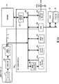
图12中所示的现有的摄像装置包括摄像元件81、模拟前端(AFE)电路82、数字图像处理电路83、SDRAM(SynchronousDynamic Random Access Memory,同步信号动态随机存取存储器)84、ROM(Read Only Memory,只读存储器)85、及存储装置86。此外,数字图像处理电路83构成为包括照相机信号前处理部91、照相机信号处理部92、分辨率转换部93、JPEG(Joint PhotographicExperts Group,联合图像专家组)引擎94、CPU(Central ProcessingUnit,中央处理器)95、视频输出编码器96、及SDRAM控制器97,并通过内部总线98相互连接这些部件。The existing imaging device shown in Fig. 12 comprises imaging element 81, analog front end (AFE)
在这样的摄像装置中,由摄像元件81产生的摄像信号依次被提供给AFE电路82,在被进行CDS(Correlated Double Sampling,相关双采样)处理、和AGC(Auto Gain Control,自动增益控制)处理之后,被转换为数字信号,并被提供给数字图像处理电路83。照相机信号前处理部91对输入的图像信号进行缺陷像素校正及遮光校正等,将其作为RAW(原始)数据,经由SDRAM控制器97写入SDRAM 84。In such an imaging device, the imaging signal generated by the imaging element 81 is sequentially provided to the
照相机信号处理部92通过SDRAM控制器97将该RAW数据从SDRAM 84读出,并执行各种检波及图像质量校正处理等(照相机信号处理),然后将其转换成亮度信号(Y)和色差信号(R-Y,B-Y)并输出。分辨率转换部93根据需要对来自照相机信号处理部92的输出图像数据进行分辨率转换处理。The camera
视频输出编码器96将通过分辨率转换部93被转换成适于显示的分辨率的图像数据转换为监视器显示用的图像信号,并输出给未图示的监视器或者视频输出端子96a。由此,可以显示出通过照相机的图像(camera through image)。JPEG引擎94根据JPEG格式将来自照相机信号处理部92或者分辨率转换部93的图像数据进行压缩编码,并暂时存储在SDRAM 84中。CPU 95将被存储于SDRAM84中的JPEG编码数据记录在存储装置86中。The
此外,CPU 95集中控制该摄像装置整体的处理,在ROM 85中记录有CPU 95执行的程序及处理所需的数据等。In addition, the
此外,虽然在上述例子中,采用的是将摄像图像作为JPEG数据加以记录的结构,但除此之外,还可以实现具备将未进行照相机信号处理等的RAW数据直接记录在记录介质中的功能的摄像装置。例如,存在如下装置(例如,参照专利文献1):其包括通过利用霍夫曼表(Huffman table)的可逆压缩方法对RAW数据进行压缩并记录的功能,且相对于每个色彩通道(color channel)进行最优化该霍夫曼表的处理。此外,也存在如下装置(例如,参照专利文献2):在设定成对RAW数据进行压缩并记录的RAW压缩模式时,绕过在通常压缩模式下使用的RAW数据的内插处理部。In addition, in the above example, the captured image is recorded as JPEG data, but in addition, it is also possible to realize the function of directly recording RAW data without camera signal processing, etc., on the recording medium. camera device. For example, there is a device (for example, refer to Patent Document 1) that includes a function of compressing and recording RAW data by a reversible compression method using a Huffman table, and with respect to each color channel (color channel) ) to optimize the Huffman table. In addition, there is also a device (for example, refer to Patent Document 2) that bypasses the interpolation processing unit for RAW data used in normal compression mode when the RAW compression mode is set to compress and record RAW data.
而且,作为相关的摄像装置,还存在如下装置(例如,参照专利文献3):对从摄像元件取入的图像数据进行可逆压缩并暂时存储于存储器之后,对该压缩数据进行解压缩并进行信号处理,进行不可逆压缩并存储于存储器。Moreover, as a related imaging device, there is also a device (for example, refer to Patent Document 3) that performs reversible compression on image data taken in from an imaging element and temporarily stores it in a memory, and then decompresses the compressed data and performs signal processing. processed, irreversibly compressed and stored in memory.
专利文献1:日本专利特开2004-40300号公报(段号〔0019〕~〔0028〕,图2)Patent Document 1: Japanese Patent Application Laid-Open No. 2004-40300 (paragraph [0019]-[0028], Figure 2)
专利文献2:日本专利特开2003-125209号公报(段号〔0027〕~〔0037〕,图1)Patent Document 2: Japanese Patent Laid-Open No. 2003-125209 (paragraph numbers [0027] to [0037], Fig. 1)
专利文献3:日本专利特开平5-191770号公报(段号〔0017〕~〔0020〕,图1)Patent Document 3: Japanese Patent Application Laid-Open No. 5-191770 (paragraph numbers [0017] to [0020], Fig. 1)
然而,如上述图12所示,在一般的摄像装置中构成为:将从摄像元件获得的RAW数据暂时存储于SDRAM等图像存储器中,然后从其中加以读出并进行照相机信号处理等。例如,当使用交错读出方式的摄像元件时等,在多个区域中一帧捕获结束类型的装置中,在将各个区域(field)的数据存储于存储器中之后,需要生成帧的数据。此外,为了抑制照相机信号处理部的行存储器(linememory)的规模,需要即使持有仅使用1H(水平同步期间)的长度的几分之一程度的延迟线来部分地(例如,以纵向的几个长方形状地)处理整个画面的处理系统时,也需要至少在该处理之前将整个画面的数据存储在存储器中。However, as shown in FIG. 12 above, a general imaging device is configured to temporarily store RAW data obtained from an imaging element in an image memory such as SDRAM, and then read it out to perform camera signal processing and the like. For example, when using an image sensor of an interleaved readout method, in a device of the type where one frame is captured in multiple fields, it is necessary to generate frame data after storing data in each field in a memory. In addition, in order to suppress the scale of the line memory (linememory) of the camera signal processing unit, it is necessary to use even a delay line that is only a fraction of the length of 1H (horizontal synchronization period) In the case of a processing system that processes the entire screen in a rectangular shape), it is also necessary to store the data of the entire screen in memory at least before the processing.
在此,在将RAW数据写入存储器及从存储器读出时,由于整个画面的数据在内部总线上流动,所以此传送需要的总线区域占用摄像时的整体总线区域的大部分。尤其摄像元件的像素数越增加且RAW数据的容量越大,则数据传送的负荷越高,存储器的写入/读出所需时间越长。因此,存在以下问题:当缩短记录处理所需时间时,需要提高传送频率等并扩大总线区域,从而装置成本增大。此外,还存在像素数越多,存储RAW数据的存储器的容量也越大的问题。Here, when RAW data is written into and read from the memory, since the data of the entire screen flows on the internal bus, the bus area required for this transfer occupies most of the entire bus area during imaging. In particular, as the number of pixels of the imaging device increases and the capacity of RAW data increases, the load on data transfer increases, and the time required for writing/reading from the memory increases. Therefore, there is a problem that, when shortening the time required for the recording process, it is necessary to increase the transmission frequency and the like and expand the bus area, thereby increasing the device cost. In addition, there is a problem that the larger the number of pixels, the larger the capacity of the memory for storing RAW data.
对此,虽然可以考虑在内部总线的传送时对RAW数据进行压缩并传送,但如果使用可变长度编码方式作为该压缩方式,则会产生传送所需要的总线区域无法固定、处理变得复杂、经常无法得到总线区域的削减效果等问题。In this regard, it is conceivable to compress and transmit RAW data during internal bus transmission, but if a variable length coding method is used as the compression method, the bus area required for transmission cannot be fixed, and the processing becomes complicated. There are often problems such as the reduction effect of the bus area not being obtained.
此外,作为RAW数据的压缩方法,也可以考虑将由一定数量的邻接的像素数据构成的块为单位进行量化,从而生成固定长度的压缩数据的方法。但是,在该方法中,如果经常以一定数量的像素为单位进行量化,则产生如下问题:量化位数越低,导致噪声越增加,尤其是在亮度的变动比较剧烈的边缘部分等上,存在产生可视觉确认程度的噪声的可能性。In addition, as a method of compressing RAW data, a method of quantizing a block consisting of a certain number of adjacent pixel data as a unit to generate compressed data of a fixed length is also conceivable. However, in this method, if quantization is often performed in units of a certain number of pixels, the following problems will arise: the lower the number of quantization bits, the more noise will increase, especially in edge parts where the brightness changes sharply, etc., there will be Possibility of producing noise of a visually recognizable level.
此外,在上述专利文献1中,是以可变长度编码化方式对RAW数据压缩,并且,在专利文献1及2两者中,都不是为了削减内部总线的区域而压缩RAW数据。此外,在专利文献3中,对于将图像数据暂时存储在存储器中时的可逆压缩方法,仅记载有取邻接像素间的差分进行霍夫曼编码的方法,而且在这种方法中,采用固定长度编码方式也很困难。In addition, in the above-mentioned
发明内容Contents of the invention
本发明鉴于上述问题,其目的在于提供可以缩短内部存储器中的图像数据的读写所需时间,并可以高速拍摄高图像质量的图像的摄像装置、摄像电路及摄像方法。In view of the above problems, an object of the present invention is to provide an imaging device, an imaging circuit, and an imaging method capable of shortening the time required for reading and writing image data in an internal memory and capable of capturing high-quality images at high speed.
为了解决上述问题,本发明提供了使用固体摄像元件拍摄图像的摄像装置,其包括:压缩部,以由邻接的一定数量的同色成分像素构成的块为单位,对通过上述固体摄像元件中的拍摄而得到的图像数据进行压缩;存储器,暂时保存被上述压缩部压缩的压缩图像数据;解压缩部,对从上述存储器读出的上述压缩图像数据进行解压缩;以及信号处理部,对通过上述解压缩部解压缩的图像数据进行图像质量校正处理,上述压缩部包括:动态范围计算部,根据由相互邻接的1个以上的像素构成的两个量化对象区域来分割上述块内的像素,并以两个上述量化对象区域的界限位置相互不同的方式预先定义多个块类型,计算全部上述块类型的上述量化对象区域中的像素数据的动态范围;块类型选择部,根据由上述动态范围计算部产生的计算结果,相对于上述块类型,计算对上述各块类型内的上述量化对象区域中的动态范围进行加法运算后的加法值,并选择上述加法值最小的上述块类型;以及量化部,相对于由上述块类型选择部选择的上述块类型的上述量化对象区域中的每个上述量化对象区域,根据通过上述动态范围计算部计算出的对应的动态范围,对从上述量化对象区域所包括的像素数据中减去上述量化对象区域中的像素数据的最小值后的值进行量化。In order to solve the above-mentioned problems, the present invention provides an imaging device that uses a solid-state imaging element to capture an image, which includes: a compression unit that, in units of a block composed of a certain number of adjacent pixels of the same color component, compresses the image captured by the solid-state imaging element The obtained image data is compressed; the memory temporarily stores the compressed image data compressed by the compression unit; the decompression unit decompresses the compressed image data read from the memory; Image quality correction processing is performed on the image data decompressed by the compression unit, and the compression unit includes a dynamic range calculation unit that divides the pixels in the block based on two quantization target regions composed of one or more pixels adjacent to each other, and uses A plurality of block types are defined in advance so that the boundary positions of the two quantization target areas are different from each other, and dynamic ranges of pixel data in the quantization target areas of all the block types are calculated; As a result of the calculation, with respect to the block type, an added value obtained by adding dynamic ranges in the quantization target area in each of the block types is calculated, and the block type with the smallest added value is selected; and a quantization section, For each of the quantization target regions of the block type selected by the block type selection unit, based on the corresponding dynamic range calculated by the dynamic range calculation unit, the Quantization is performed by subtracting the minimum value of the pixel data in the above-mentioned quantization target area from the pixel data.
在这样的摄像装置中,通过拍摄获得的图像数据通过压缩部被压缩,该压缩图像数据被暂时存储于存储器中,然后通过解压缩部对从存储器读出的压缩图像数据进行解压缩,由信号处理部对被解压缩的图像数据进行图像质量校正处理。在压缩部中,以由邻接的一定数量的同色成分像素构成的块为单位生成压缩图像数据,在该量化时,会从预先定义的多个块类型中选择适合的块类型。以以下方式分别定义多个块类型:根据由相互邻接的1个以上的像素构成的两个量化对象区域分割块内像素,并且两个量化对象区域的界限位置互不相同。在压缩部中,比较各个块类型内的量化对象区域中的动态范围的加法值,并选择加法值最小的块类型。然后,相对于选择的块类型中的每个量化对象区域,将从这些量化对象区域中包括的像素数据中减去该量化对象区域中的像素数据的最小值后的值根据与该量化对象区域相对应的动态范围进行量化。In such an imaging device, image data obtained by shooting is compressed by a compression section, the compressed image data is temporarily stored in a memory, and then the compressed image data read from the memory is decompressed by a decompression section, and the compressed image data read from the memory is decompressed by a signal The processing unit performs image quality correction processing on the decompressed image data. In the compression unit, compressed image data is generated in units of blocks composed of a certain number of adjacent same-color component pixels, and when quantizing, an appropriate block type is selected from a plurality of predefined block types. Each of the plurality of block types is defined in such a manner that the pixels in the block are divided based on two quantization target areas composed of one or more adjacent pixels, and the boundary positions of the two quantization target areas are different from each other. In the compression unit, the added value of the dynamic range in the quantization target area in each block type is compared, and the block type with the smallest added value is selected. Then, with respect to each quantization target area in the selected block type, the value obtained by subtracting the minimum value of the pixel data in the quantization target area from the pixel data included in the quantization target area The corresponding dynamic range is quantified.
在本发明的摄像装置中,在直至通过信号处理部对拍摄图像数据进行图像质量校正处理为止的步骤中,因为通过存储器读写的图像数据被压缩,所以可以缩短存储器中的图像数据的读写所需时间。此外,通过压缩,以由邻接的一定数量的同色成分像素构成的块为单位来生成压缩图像数据,在该压缩时,分别定义具有不同的两个量化对象区域的多个块类型,并将各块类型内的量化对象区域中的动态范围的加法值进行比较,选择加法值最小的块类型,相对于该块类型中的每个量化对象区域,根据动态范围量化数据,所以可以根据块内的图像状态选择可以将由量化产生的图像质量劣化抑制在最小限度的优选的块类型,并执行量化处理。因此,可以通过高速的处理获得高图像质量的拍摄图像。In the imaging device of the present invention, in the steps until the image quality correction processing is performed on the captured image data by the signal processing unit, since the image data read and written by the memory is compressed, the reading and writing of the image data in the memory can be shortened. time required. In addition, by compression, compressed image data is generated in units of blocks composed of a certain number of adjacent same-color component pixels. In this compression, a plurality of block types having two different quantization target areas are respectively defined, and each The additive value of the dynamic range in the quantization target area in the block type is compared, and the block type with the smallest additive value is selected. With respect to each quantization target area in the block type, the data is quantized according to the dynamic range, so it can be based on the dynamic range in the block type. The image state selects a preferred block type that can minimize image quality degradation due to quantization, and executes quantization processing. Therefore, a captured image of high image quality can be obtained through high-speed processing.
附图说明Description of drawings
图1是表示本发明的第一实施例涉及的摄像装置的结构的框图;FIG. 1 is a block diagram showing the configuration of an imaging device according to a first embodiment of the present invention;
图2是用于说明作为压缩单位的块的图;FIG. 2 is a diagram for explaining a block as a compression unit;
图3是用于说明确定块类型的确定方法的图;FIG. 3 is a diagram for explaining a determination method of determining a block type;
图4是表示RAW压缩部的内部构成的框图;FIG. 4 is a block diagram showing an internal configuration of a RAW compression unit;
图5是表示折线压缩部所使用的折线的示例的图;FIG. 5 is a diagram showing an example of polygons used by a polygon compression unit;
图6是表示通过打包(packing)生成的1个块的压缩数据的构成的图;Fig. 6 is a diagram showing the configuration of compressed data of one block generated by packing;
图7是表示块类型确定部的内部构成的图;FIG. 7 is a diagram showing an internal configuration of a block type specifying unit;
图8是表示RAW解压缩部的内部构成的框图;8 is a block diagram showing the internal configuration of a RAW decompression unit;
图9是表示在逆折线转换部中使用的折线的示例的图;FIG. 9 is a diagram showing an example of polylines used in an inverse polyline conversion unit;
图10是概略地表示本发明的第二实施例涉及的摄像装置的构成的框图;10 is a block diagram schematically showing the configuration of an imaging device according to a second embodiment of the present invention;
图11是概略地表示本发明的第三实施例涉及的摄像装置的构成的框图;以及11 is a block diagram schematically showing the configuration of an imaging device according to a third embodiment of the present invention; and
图12是表示现有技术的摄像装置的构成例的框图。FIG. 12 is a block diagram showing a configuration example of a conventional imaging device.
具体实施方式Detailed ways
下面参照附图,对本发明的实施例进行详细说明。Embodiments of the present invention will be described in detail below with reference to the accompanying drawings.
〔第一实施例〕[First embodiment]
图1是表示本发明的第一实施例涉及的摄像装置的构成的框图。FIG. 1 is a block diagram showing the configuration of an imaging device according to a first embodiment of the present invention.
图1所示的摄像装置包括摄像元件11、AFE电路12、数字图像处理电路13、SDRAM 14、ROM 15及存储装置16。此外,数字图像处理电路13构成为包括照相机信号前处理部21、照相机信号处理部22、分辨率转换部23、JPEG引擎24、CPU 25、视频输出编码器26、及SDRAM控制器27,并通过内部总线28相互连接这些部件。而且,在这些现有技术的结构的基础上,本实施例的数字图像处理电路13还具有RAW压缩部31及RAW解压缩部32。The imaging device shown in FIG. 1 includes an
摄像元件11是例如CCD(Charge Coupled Devices,电荷耦合器件)、CMOS(Complementary Metal Oxide Semiconductor,互补型金属氧化物半导体)型图像传感器等的固体摄像元件,其通过未图示的镜头部件(lens block)将从被拍摄对象入射的光转换成电信号。The
AFE电路12通过CDS处理对从摄像元件11输出的图像信号进行采样保持(sample hold),以良好地确保S/N(Signal/Noise,信噪比)比,进而通过AGC处理控制增益(gain),进行A/D(Analog/Digital,模拟/数字)转换,从而输出数字图像信号。The
数字图像处理电路13形成为例如SoC(System On a Chip,系统芯片)电路等。在该数字图像处理电路13中,照相机信号前处理部21对从AFE电路12提供的图像信号进行摄像元件11中的缺陷像素的信号校正处理、对镜头(lens)的周围光量降低进行校正的遮光(shading)处理等,并将处理后的信号作为RAW数据加以输出。The digital image processing circuit 13 is formed as, for example, a SoC (System On a Chip) circuit or the like. In this digital image processing circuit 13, the camera signal pre-processing section 21 performs signal correction processing for defective pixels in the
RAW压缩部31将来自照相机信号前处理部21的RAW数据通过后述压缩方法进行压缩,并经由SDRAM控制器27提供给SDRAM 14。The
RAW解压缩部32将从SDRAM 14经由SDRAM控制器27读出的被压缩的RAW数据通过后述的方法进行解压缩并输出给照相机信号处理部22。The
照相机信号处理部22对来自RAW解压缩部32的RAW数据进行去马赛克(de-mosaic)处理之后,执行用于AF(Auto focus,自动调焦)、AE(Auto Exposure,自动曝光)及白平衡控制等的信号检波处理、以及白平衡调整所代表的图像质量校正处理等所谓的照相机信号处理或者该处理的一部分。而且,将图像质量校正后的图像数据转换成例如4:2:2等规定格式的亮度信号(Y)和色差信号(R-Y,B-Y)。The camera signal processing unit 22 performs demosaic (de-mosaic) processing on the RAW data from the
分辨率转换部23接受被照相机信号处理部22处理的图像数据、或者被JPEG引擎24解压缩解码的图像数据的输入,并将其转换成规定的分辨率。The
JPEG引擎24将被分辨率转换部23处理的图像数据进行压缩编码,并生成JPEG方式的编码数据。此外,将从存储装置16中读出的JPEG图像数据进行解压缩解码。此外,也可以在数字图像处理电路13中设置该JPEG引擎24以外的其他的静止图像压缩方式或者运动图像压缩方式的编码/解码引擎(engine)。The
CPU 25通过执行存储于ROM 15的程序来集中控制该数字图像处理电路13及整个摄像装置,此外,CPU 25还执行用于该控制的各种运算。The
视频输出编码器26被构成作为例如NTSC(National TelevisionStandards Committee,美国国家电视标准委员会)编码器等,视频输出编码器26根据从分辨率转换部23等输出的图像数据,生成监视器显示用的图像信号,并输出给未图示的监视器或者视频输出端子26a。The
SDRAM控制器27是与SDRAM 14相对的接口块,其具有地址解码器等,SDRAM控制器27根据来自CPU 25的控制信号来控制在SDRAM 14中的数据的写入动作及读出动作。The
SDRAM 14是被准备作为用于数字图像处理电路13中的数据处理的工作区域的易失性存储器。该SDRAM 14的内部区域被利用作为捕获数据区域14a、JPEG编码区域14b、以及CPU工作区域14c等,其中,捕获数据区域14a用于暂时存储从摄像元件11捕获的数据、即被RAW压缩部31压缩的RAW数据,JPEG编码区域14b用于暂时存储通过JPEG引擎24编码的图像数据及在该编码、解码处理中被利用的数据等,CPU工作区域14c用于暂时存储在CPU 25的处理中被利用的数据。The
ROM 15保存CPU 25执行的程序及各种数据。也可以使用例如EEPROM(Electronically Erasable and Programmable ROM,电擦写可编程只读存储器)、闪存等非易失性存储器作为该ROM 15。The
存储装置16是用于记录被编码的图像数据的文件的装置,其构成为包括例如闪存、光盘、磁带等记录介质、及它们的记录/再生驱动器等。The
在这种摄像装置中,由摄像元件11产生的摄像信号依次被提供给AFE电路12,且在被进行CDS处理和AGC处理等之后,被转换成数字信号,从而提供给数字图像处理电路13的照相机信号前处理部21。在照相机信号前处理部21中,对被输入的图像信号进行缺陷像素校正和遮光校正等后生成RAW数据,该RAW数据通过RAW压缩部31进行压缩之后,被暂时写入SDRAM 14。In such an imaging device, the imaging signal generated by the
该RAW数据当从SDRAM 14中被读出时,通过RAW解压缩部(raw-data decompression section)32解压缩,然后通过照相机信号处理部22进行各种图像质量校正处理。处理后的图像数据被暂时存储于例如SDRAM 14,然后通过分辨率转换部23被转换为具有适于显示的分辨率的数据,被进一步存储于例如SDRAM 14后,被提供给视频输出编码器26。由此,通过照相机的图像被显示在监视器上。This RAW data, when read from the
此外,当通过未图示的输入部等要求记录图像时,分辨率转换部23根据需要将被照相机信号处理部22处理的图像数据转换成具有被设定用于记录的分辨率的数据,并暂时存储在例如SDRAM 14中,JPEG引擎24将该图像数据进行压缩编码并生成编码数据。编码数据被暂时记录于例如SDRAM 14,然后被记录在存储装置16中。In addition, when recording an image is requested through an input unit not shown, etc., the
此外,被记录在存储装置16中的图像数据(编码数据)可以在JPEG引擎24中被解压缩解码,并被分辨率转换部23进行分辨率转换之后,被输出给视频输出编码器26,从而显示在监视器上。In addition, the image data (encoded data) recorded in the
在这样的数字图像处理电路13中,通过在从照相机信号前处理部21对内部总线28输入图像数据的输入位置上设置用于对RAW数据进行压缩的RAW压缩部31,从而可以减少通过内部总线28传送到SDRAM 14的RAW数据的数据量。此外,通过在从内部总线28对照相机信号处理部22输入图像数据的输入位置上设置用于对RAW数据进行解压缩的RAW解压缩部32,同样可以减少从SDRAM 14向照相机信号处理部22传送的RAW数据的数据量。In such a digital image processing circuit 13, by providing the
由此,可以减少拍摄动作中的内部总线28的传送负荷,并可缩短SDRAM 14中的写入/读出处理所需的时间。尤其是,通过尽可能地简化压缩/解压缩的处理,从而可以提高处理时间的缩短效果。此外,也可降低总线上的传送频率,并可以抑制功耗。As a result, the transfer load on the
此外,可以减小SDRAM 14的容量。或者,也可以赋予将SDRAM 14的区域利用于其他处理的、存储多帧RAW数据来增加可连拍张数或者提高连拍速度等高图像质量化、高功能化。因此,可以实现缩短拍摄及数据记录所需时间的、高性能并且小型、低成本的摄像装置。Furthermore, the capacity of
但是,在基于RAW压缩部31的RAW数据的压缩处理中,虽然通过使用可逆压缩方法(reversible compression technique),可以完全地保持RAW数据的品质,但即使是不可逆压缩,如果压缩失真(conpression distortion)的发生量在被转换成亮度/色差信号时为肉眼所不能感知的程度,则作为图像质量也是可以容许的。一般而言,如果被转换成亮度/色差信号时的PSNR(Peak Signal to NoiseRatio,峰值信噪比)为50dB~40dB程度,则压缩失真为可容许的水平(level)。However, in the compression process of the RAW data by the
而且,在压缩RAW数据时,如果可以固定长度进行编码,则可以将对SDRAM 14进行读写的RAW数据的区域保持为一定,于是可以稳定地减少在内部总线28中的传送负荷。此外,也可以简化照相机信号处理部22中的RAW数据的处理(例如从SDRAM 14进行读出的控制处理)、及通过内部总线28的RAW数据的传送控制处理等。Furthermore, if the RAW data can be encoded at a fixed length when compressing the RAW data, the area of the RAW data to be read and written to the
例如,在以可变长度进行编码的情况下,当在从SDRAM14读出被压缩的RAW数据时,大多必须突发地进行存取(burst access)。此外,当作为照相机信号处理部22的功能,存在以持有1H的几分之一程度的延迟线(delay line)的方式部分式地(例如以纵向短条状)处理整体画面的功能的情况下,通过以固定长度进行编码,可以简单地计算任意位置的RAW数据在SDRAM14上的地址并进行读取。也可以通过数字图像处理电路13内的DMA(Direct MemoryAccess,直接存储器存取)控制器进行存取。For example, in the case of variable-length encoding, when reading compressed RAW data from the
因此,在本实施例中,如下所述,可以采用不可逆压缩/解压缩方法,其可进行固定长度的编码,并可良好地保持图像品质,还可实现比较简单的处理。尤其是,在该方法中,可通过将由一定数量的邻接像素构成的块根据其图像状态进一步分割,并相对于每个分割区域进行压缩处理,从而可以进一步抑制由压缩引起的图像质量劣化。Therefore, in this embodiment, as described below, an irreversible compression/decompression method can be employed, which can perform fixed-length encoding, can maintain image quality well, and can also achieve relatively simple processing. In particular, in this method, image quality degradation caused by compression can be further suppressed by further dividing a block composed of a certain number of adjacent pixels according to its image state and performing compression processing for each divided area.
下面,对在本实施例中所采用的图像压缩方法的概要进行说明。首先,图2是用于说明作为压缩单位的块的图。Next, an outline of the image compression method employed in this embodiment will be described. First, FIG. 2 is a diagram for explaining a block as a compression unit.
在本实施例所采用的图像压缩方法中,以由邻接的一定数量的同色成分像素构成的块(block)为单位,以固定的压缩率进行数据压缩。构成该块的像素可以是仅沿水平方向或者垂直方向邻接的像素,也可以是跨越多列或多行地邻接的像素。在下面的例子中,如图2所示,将6像素×2行合计12像素作为1个块进行压缩。此外,在图2中,虽然仅示出了在以采用拜尔阵列(Bayer array)的摄像元件11为例的情况下,将r成分的像素排列作为1个块的状态,但是当然gr成分、gb成分、b成分也同样被排列作为6像素×2行的块。In the image compression method adopted in this embodiment, data compression is performed at a fixed compression rate in units of a block composed of a certain number of adjacent pixels of the same color component. The pixels constituting the block may be adjacent only in the horizontal or vertical direction, or may be adjacent across a plurality of columns or rows. In the following example, as shown in FIG. 2 , 6 pixels x 2 rows totaling 12 pixels are compressed as one block. In addition, in FIG. 2, although the
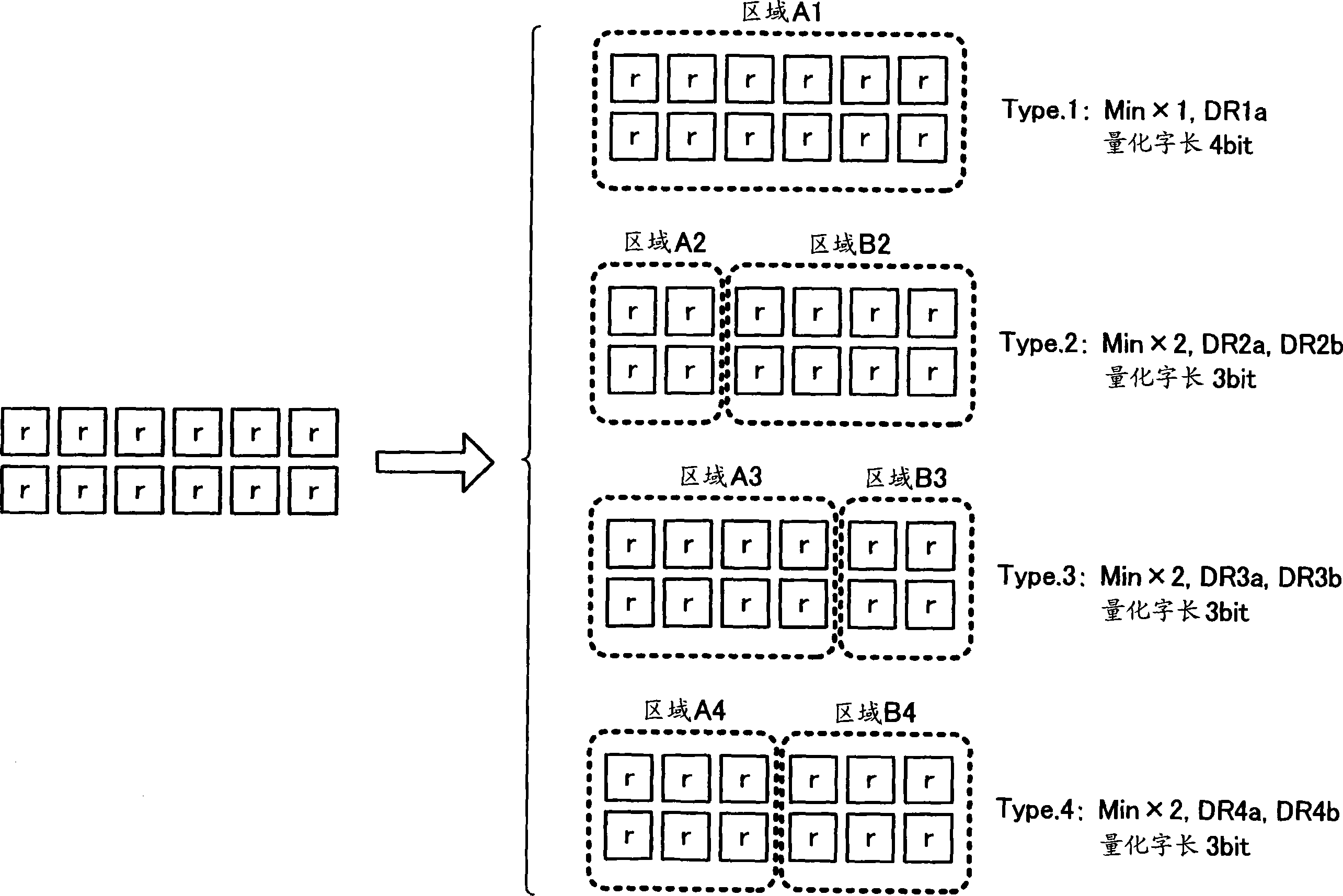
图3是用于说明确定块类型(block type)的确定方法的图。FIG. 3 is a diagram for explaining a method of determining a block type.
在本实施例中,可以将由如上所述邻接的12像素构成的块根据该块中的数据的状态,通过如图3所示的四种分割模式中的任一种模式进行分割,并生成压缩数据。In this embodiment, a block composed of adjacent 12 pixels as described above can be divided according to the state of the data in the block by any one of the four division modes shown in Figure 3, and a compressed data.
在块类型1中,不对块进行分割而将其作为1个区域A1。在块类型2中,将块分割成由2像素×2行的4像素构成的区域A2和由残留的4像素×2行的8像素构成的区域B2。在块类型3中,将块分割成由4像素×2行的8像素构成的区域A3和由残留的2像素×2行的4像素构成的区域B3。在块4中,将块分割成由3像素×2行的6像素构成的区域A4及区域B4。In the
通过本实施例的数据压缩方法生成的每个块的压缩数据基本上构成为包括:由指定区域内的最小值(DC偏移(offset)成分);与该区域内的数据的动态范围(最大值与最小值的差分值)相对应的值;以及通过动态范围而标准化的各像素的量化数据。而且,这些压缩数据相对于每个块为相同的数据量。因此,当将像素数据的量化字长(quantized-word length)设定为相同时,区域内的动态范围越宽,量化的精度越低。The compressed data of each block generated by the data compression method of this embodiment is basically constituted to include: the minimum value (DC offset (offset) component) in the specified area; value corresponding to the difference between the value and the minimum value); and the quantized data of each pixel normalized by the dynamic range. Furthermore, these compressed data are the same amount of data per block. Therefore, when the quantized-word length of the pixel data is set to be the same, the wider the dynamic range in the region, the lower the precision of the quantization.
因此,在本实施例中,相对于上述4个块类型中的每个分割区域计算块内的动态范围,并根据该计算结果,从上述块类型中选择适合的块类型,以使各分割区域中的动态范围尽可能地狭窄。例如,在块内,当在从左侧第二像素与第三像素之间的区域存在明暗边缘(edge)时,选择块类型2,在区域A2和区域B2分别计算动态范围,根据这些计算结果量化图像数据。由此,区域A2和区域B2的各自的动态范围变窄,各区域的量化精度得到提高。此外,也可缩短量化字长。相反当块整体的像素电平差小时,选择块类型1,即使根据区域A1(即块整体)的动态范围来量化图像数据,也可以抑制量化的精度劣化。Therefore, in this embodiment, the dynamic range within a block is calculated for each of the above-mentioned four block types, and based on the calculation result, an appropriate block type is selected from the above-mentioned block types so that each of the divided areas The dynamic range in is as narrow as possible. For example, in a block, when there is a light and dark edge (edge) in the area between the second pixel and the third pixel from the left,
此外,如图3所示,在该数据压缩方法中,当选择块类型1时,在压缩数据中包括区域A1的动态范围DR1a及最小值。此外,当选择块类型2时,在压缩数据中包括区域A2的动态范围DR2a及最小值、区域B2的动态范围DR2b及最小值。同样,当选择块类型3时,在压缩数据中包括区域A3的动态范围DR3a及最小值、区域B3的动态范围DR3b及最小值。此外,当选择块类型4时,在压缩数据中包括区域A4的动态范围DR4a及最小值、区域B4的动态范围DR4b及最小值。Furthermore, as shown in FIG. 3, in this data compression method, when the
下面,对使用这样的块类型的压缩/解压缩处理进行更为具体的说明。此外,在此,以在每个像素中,将从照相机信号前处理部21输出的RAW数据设定为14位(bit)的数据的情况为例。而且,将邻接的同色成分的12像素作为1个块,以块为单位固定的压缩率的方式进行数据压缩。具体而言,将每个块168位的RAW数据压缩成64位的数据。此外,如图3所示,仅将块类型1的像素数据的量化字长设定为4位,将其他的块类型中各分割区域设定为3位。Next, the compression/decompression processing using such a block type will be described more specifically. In addition, here, the case where the RAW data output from the camera signal pre-processing part 21 is set as 14-bit data for every pixel is taken as an example. Then, 12 adjacent pixels of the same color components are regarded as one block, and data compression is performed so that the compression ratio is fixed in block units. Specifically, 168-bit RAW data per block is compressed into 64-bit data. In addition, as shown in FIG. 3 , only the quantization word length of the pixel data of
图4是表示RAW压缩部内部构成的框图。Fig. 4 is a block diagram showing the internal configuration of a RAW compression unit.
如图4所示,RAW压缩部31包括折线压缩部(polygonal-lineconversion/compression block)101、延迟线102、块化部(data blockingblock)103、最大/最小检测部104、块类型确定部105、选择器106、缓冲器107、减法器108、量化部(quantization block)109、移位量计算部110、量化数据缓冲器111、及打包部(packing block)112。As shown in FIG. 4 , the
折线压缩部101通过利用折线的近似,将输入的14位的RAW数据以非线形的方式压缩成10位的数据。该折线压缩部101的设置目的是为了在此后的压缩步骤之前,通过尽可能地降低灰度,从而提高整体的压缩效率。因此,根据作为目的的压缩率,也可以省略折线压缩部101。此外,在这种情况下,也需要省略被设置在后面的图8中所说明的在RAW解压缩部32的输出级上的逆折线转换部。The polygonal
此处,图5是表示折线压缩部所使用折线的例子。Here, FIG. 5 shows an example of the broken lines used by the broken line compression unit.
在图5中通过以四点分割的具有5种倾斜度的直线来表示转换输入数据的灰度的例子。在此例中,配合人的视觉特性,输入数据越小、即越暗(或者颜色越浅),分配越高的灰度。这种折线也可以相对于例如颜色成分而准备,并相当于输入像素的颜色成分进行切换加以利用。In FIG. 5 , an example of the gradation of the conversion input data is represented by straight lines having five types of inclinations divided by four points. In this example, in accordance with human visual characteristics, the smaller the input data, that is, the darker (or the lighter the color), the higher the grayscale assigned. Such polylines may be prepared for, for example, color components, and may be used by switching corresponding to color components of input pixels.
在折线压缩部101中,例如,使用这样折线,将输入数据的灰度进行转换之后,将转换后的数据除以16(即向下移位4位),并压缩成10位的数据。此时,对剩下的下位位进行例如四舍五入。或者,也可以在折线压缩部101中,对应输入数据和基于上述运算的压缩后的输出数据而准备存储的ROM表,并根据该ROM表进行输入输出数据的转换。In the polygonal
下面返回到图4进行说明。Return to FIG. 4 below for description.
延迟线102使从折线压缩部101输出的数据仅延迟1H。块化部103根据从折线压缩部101输出的数据、和通过延迟线102延迟的前一行的数据,输出被分离成由上述的6像素×2行的12像素构成的每个块的数据。此外,此处以输入RAW压缩部31的RAW数据是按颜色成分被分离的数据的情况为例。The
最大/最小检测部104接受被分离成每个块的同色像素的数据的输入,并相对于上述所有块类型的分割区域检测出最大值及最小值。各分割区域的最大值及最小值被输出给块类型确定部105,其中的最小值还被输出给选择器106。The maximum/
块类型确定部105根据来自最大/最小检测部104的每个分割区域的最大值及最小值而确定适当的块类型,以便使分割区域的动态范围变为最小。并且,将表示所确定的块类型的标识码对打包部112进行输出,同时,将与确定的块类型相对应的分割区域的动态范围对移位量计算部110进行输出。而且,将与确定的块类型相对应的选择信号对选择器106进行输出。The block
选择器106在从最大/最小检测部104输出的各分割区域的最小值中,选择与来自块类型确定部105的选择信号相对应的值,输出给打包部112及减法器108。由此,从选择器106输出与由块类型确定部105确定的块类型相对应的分割区域的最小值。The
缓冲器107使来自块化部103的数据仅延迟相当于与在最大/最小检测部104及选择器106中的处理时间相对应的时间,并使对减法器108输出数据的输出时刻与从选择器106向减法器108输出数据的输出时刻相一致。The
减法器108计算从块化部103经由缓冲器107输入的1个块的像素数据中减去来自选择器106的最小值。在此,来自选择器106的最小值被分别输出给通过块类型确定部105确定的块类型所包含的分割区域,在减法器108中,从来自缓冲器107的像素数据中减去与该像素所属的分割区域相对应的最小值。其结果是,通过减法器108,可从被作为减算对象的像素数据中除去该像素所属的分割区域中的DC偏移成分的数据,并可将在量化部109中的量化字长设定得更短。The
在此,以从块化部103对减法器108并列输入两行的像素数据,并执行减算的情况为例。在这种情况下,例如,当由块类型确定部105确定块类型2时,首先,在从缓冲器107向减法器108输入直至块内第一个及第二个为止的像素的数据的期间,从选择器106向减法器108输入区域A2的最小值,并执行减算。然后,在将直至块内的第三个到第六个为止的像素的数据输入给减法器108的期间,从选择器106向减法器108输入区域B2的最小值,并执行减算。Here, a case where two rows of pixel data are input in parallel from the blocking
量化部109对通过减法器108去除DC偏移成分的像素数据进行量化。作为该量化部109,可以适用例如如下结构:利用整数型的除法器,将减法器108的输出数据除以来自选择器106的动态范围。但是,在此,将量化步骤(quantization step)作为2的幂乘,并将量化部109作为根据从移位量计算部110指定的移位量而使输入数据向下位侧移位的右移位器而实现,由此,可以减少量化数据的位数,还可抑制电路规模。The
此外,在本实施例中,由于每个块的压缩数据被设定为64位的固定长度,所以在块类型1情况下,将量化部109中的量化字长设定为4位,在块类型2~4的情况下,将量化部109中的量化字长设定为3位。但是,在量化部109中,通常输出4位数据,在打包部112中将量化数据打包成压缩数据时,将不要的位的数据舍弃即可。In addition, in this embodiment, since the compressed data of each block is set to a fixed length of 64 bits, in the case of
移位量计算部110从块类型确定部105接受各分割区域的动态范围,将这些动态范围的值换算成在量化部109中的移位量。在此,根据通过块类型确定部105确定的块类型,执行两种动作。The shift
首先,在块类型1的情况下,在量化部109中将10位的数据量化成4位的数据。在这种情况下,当将来自块类型确定部105的动态范围的值设为DR时,移位量计算部110按以下条件计算移位量。First, in the case of
[0≤DR≤15时]直接对输入数据进行输出。[0≤DR≤15] directly output the input data.
[16≤DR≤31时]将输入数据向下位移位1位。[When 16≤DR≤31] Shift the input data down by 1 bit.
[32≤DR≤63时]将输入数据向下位移位2位。[When 32≤DR≤63] Shift the input data down by 2 bits.
[64≤DR≤127时]将输入数据向下位移位3位。[When 64≤DR≤127] Shift the input data down by 3 bits.
[128≤DR≤255时]将输入数据向下位移位4位。[When 128≤DR≤255] Shift the input data down by 4 bits.
[256≤DR≤511时]将输入数据向下位移位5位。[When 256≤DR≤511] Shift the input data down by 5 bits.
[512≤DR≤1023时]将输入数据向下位移位6位。[When 512≤DR≤1023] Shift the input data down by 6 bits.
另一方面,当块类型2~4的情况下,在量化部109中将10位的数据量化成3位的数据,移位量计算部110按以下条件计算移位量。On the other hand, in the case of
[0≤DR≤7时]直接对输入数据进行输出。[0≤DR≤7] directly output the input data.
[8≤DR≤15时]将输入数据向下位移位1位。[When 8≤DR≤15] Shift the input data down by 1 bit.
[16≤DR≤31时]将输入数据向下位移位2位。[When 16≤DR≤31] Shift the input data down by 2 bits.
[32≤DR≤63时]将输入数据向下位移位3位。[When 32≤DR≤63] Shift the input data down by 3 bits.
[64≤DR≤127时]将输入数据向下位移位4位。[When 64≤DR≤127] Shift the input data down by 4 bits.
[128≤DR≤255时]将输入数据向下位移位5位。[When 128≤DR≤255] Shift the input data down by 5 bits.
[256≤DR≤511时]将输入数据向下位移位6位。[When 256≤DR≤511] Shift the input data down by 6 bits.
[512≤DR≤1023时]将输入数据向下位移位7位。[When 512≤DR≤1023] Shift the input data down by 7 bits.
根据以上条件而计算出的移位量表示对应的分割区域中的动态范围。因此,通过将这样的移位量及根据该移位量而生成的量化数据存储在压缩数据中,从而可以在解压缩部侧根据移位量而对量化数据进行解压缩。The shift amount calculated based on the above conditions indicates the dynamic range in the corresponding divided area. Therefore, by storing such a shift amount and quantized data generated based on the shift amount in the compressed data, the quantized data can be decompressed in accordance with the shift amount on the decompression unit side.
量化数据缓冲器111暂时保存从量化部109输出的1个块(12像素)的量化数据。The quantized
打包部112利用来自量化数据缓冲器111的各个像素的量化数据、来自选择器106的每个分割区域的最小值、来自移位量计算部110的每个分割区域的移位量、以及用于识别来自块类型确定部105的块类型的标识码,将其打包成每1个块64位的压缩数据。
图6是表示通过打包生成的1个块的压缩数据的构成的图。FIG. 6 is a diagram showing the structure of compressed data of one block generated by packing.
如图6所示,在RAW压缩部31中,生成相对于块类型而不同的4种的压缩数据。将这些压缩数据全部被压缩成每个块64位,此外,被配置在开头用于识别块类型的2位的标识码是共通的。As shown in FIG. 6 , in the
在块类型1的情况下,接着标识码,配置有与区域A1相对应的最小值(10位)、量化处理时的移位量(3位)、区域A1内的12像素的量化数据(各4位),最后设置有用于合计为64位的1位空白区域。In the case of
在块类型2~4的情况下,接着标识码,首先配置有与区域A(区域A2~A4中的任一个)相对应的最小值(10位)及移位量(3位),然后配置有与区域B(区域B2~B4中的任一个)相对应的最小值(10位)及移位量(3位)。其后,配置有区域A内的各像素的量化数据(3位),然后配置有区域B内各像素的量化数据(3位)。即在块类型2~4中,虽然最小值和移位量的配置区域是共通的,但是因为分割区域的像素数不同,所以在解压缩部侧需要根据标识码来对每个分割区域的量化数据的存储位置进行判断。In the case of
另外,在不对像素数据的量化使用位移位器(bit shifter)的情况下,也可以例如,取代上述移位量而将量化时使用的动态范围的数值本身打包在压缩数据中。In addition, when a bit shifter is not used for quantization of pixel data, for example, instead of the shift amount described above, the numerical value itself of the dynamic range used for quantization may be packed in the compressed data.
此外,虽然在上述例子中是对将各分割区域的最小值从像素数据中减去后的值进行量化,但作为其他例子,也可以仅对从除了分割区域中的最小值和最大值以外的像素数据中分别减去最小值后的值进行量化。在这种情况下,将在压缩数据中,在分割区域中不需要采用最小值及最大值的像素的量化数据取而代之,而是在压缩数据中包括各分割区域的最大值、最小值及最大值在分割区域中的位置信息。也可以根据确定位置信息的位数的块内或者分割区域内的像素数、图像数据的位数、量化字长、每个块的压缩数据的数据量等来适当确定选择此例和图6的例子中哪一个。In addition, although in the above-mentioned example, the value obtained by subtracting the minimum value of each divided area from the pixel data is quantized, as another example, only the values other than the minimum value and maximum value in the divided area may be quantized. Quantization is performed by subtracting the minimum value from the pixel data. In this case, in the compressed data, instead of the quantized data of pixels that do not need to use the minimum value and maximum value in the divided area, the compressed data includes the maximum value, minimum value, and maximum value of each divided area. Position information in the segmented area. It is also possible to appropriately determine and select this example and the one in FIG. which one of the examples.
接下来,图7是表示块类型确定部的内部构成的图。Next, FIG. 7 is a diagram showing the internal configuration of the block type specifying unit.
块类型确定部105包括动态范围运算部131、动态范围加法部132、动态范围比较部133、选择器134、地址计数器135及选择信号生成部136。The block
动态范围运算部131相对于所有块类型的分割区域(区域A1~A4、B2~B4)中的每个分割区域计算出动态范围DR1a、DR2a、DR2b、DR3a、DR3b、DR4a、DR4b。在此,通过从最大/最小检测部104按每个分割区域输出的最大值中减去最小值,从而对各分割区域中的动态范围进行运算。这些运算结果被输出给动态范围加法部132及选择器134。The dynamic
动态范围加法部132根据来自动态范围运算部131的各分割区域的动态范围,计算出各块类型的动态范围加法值。在此,通过下式(1)~(4),对块类型1~4中的各个块类型的动态范围加法值DR1~DR4进行运算。The dynamic
DR1=DR1a ……(1)DR1=DR1a ... (1)
DR2=DR2a+DR2b ……(2)DR2=DR2a+DR2b ...(2)
DR3=DR3a+DR3b ……(3)DR3=DR3a+DR3b ...(3)
DR4=DR4a+DR4b ……(4)DR4=DR4a+DR4b ...(4)
动态范围比较部133将来自动态范围加法部132的动态范围加法值进行比较,确定与最小值相对应的块类型,并将表示该块类型的2位的标识码输出给选择信号生成部136、移位量计算部110及打包部112。The dynamic
选择器134根据来自选择信号生成部136的选择信号,输出在从动态范围运算部131输出的动态范围中的、与1个块类型相对应的动态范围。The
地址计数器135将最大/最小检测部104中的1块的最大值及最小值的检测完毕定时作为触发(trigger),并与来自最大/最小检测部104的数据输出定时同步地对地址进行计数。The
选择信号生成部136根据来自动态范围比较部133的标识码,在基于地址计数器135的规定的计数值的输出定时,对选择器134及106输出选择信号。通过该选择信号控制在选择器134及106中,按预先确定的顺序输出与通过标识码指定的块类型相对应的值。The selection
例如,当标识码表示块类型1时,向选择器134输出区域A1的动态范围DR1a,向选择器106输出区域A1中的最小值。此外,当标识码表示块类型2时,首先,向选择器134输出区域A2的动态范围DR2a,向选择器106输出区域A2中的最小值。然后,向选择器134输出区域B2的动态范围DR2b,向选择器106输出区域B2中的最小值。For example, when the identification code indicates
同样,当标识码表示块类型3时,首先,向选择器134及106分别输出区域A3的动态范围DR3a及最小值之后,分别输出区域B3的动态范围DR3b及最小值。此外,当标识码表示块类型4时,首先,向选择器134及106分别输出区域A4的动态范围DR4a及最小值,然后分别输出区域B4的动态范围DR4b及最小值。Similarly, when the identification code indicates
在上面的块类型确定部105中,可以根据式(1)~(4),通过选择动态范围加法值最小的块类型,从而根据块内图像的状态,对量化对象区域进行合适化处理,以使图像质量劣化减少。但是,在公式(2)~(4)中,由于对两个分割区域中的动态范围进行加法处理,所以为了与这些加法值进行正确的比较,也可以将式(1)设定为:DR1=DR1a×2(或者,也可以将式(2)~(4)的加法值分别再乘以1/2)。In the above block
但是,在块类型1中,将最小值和移位量仅以1个区域的方式存储在压缩数据中即可,为此,可以将量化字长设定得比其他的块类型大(4位)。因此,在块类型1中,由于可以认为与其他块类型相比可以容许的动态范围的范围更大,所以在本实施例中,如式(1)所示,设定DR1=DR1a,易于相对地选择块类型1。通过这样的加权处理,还存在以下优点:可以防止例如对噪声等产生反应而选择具有不适当的分割区域的块类型这样的错误动作的发生。However, in
而且,也可以通过基于用户的输入操作,将基于与块类型1相对应的动态范围加法值的运算式中的乘数任意设定在1~2的范围内。Furthermore, the multiplier in the calculation formula based on the dynamic range addition value corresponding to the
其次,图8是表示RAW解压缩部的内部构成的框图。Next, FIG. 8 is a block diagram showing the internal configuration of the RAW decompression unit.
如图8所示,RAW解压缩部包括数据锁存部201、选择器202~204、地址计数器205、逆量化部206、加法器207及逆折线转换部208。As shown in FIG. 8 , the RAW decompression unit includes a
数据锁存部201锁存从SDRAM 14中读出的64位的压缩数据。该数据锁存部201根据开头2位的标识码来判定块类型,然后根据该判定结果,辨别各分割区域的最小值及移位量、各分割区域内的像素的量化数据的存储位置,并进行锁存(闩锁)。The data latch
选择器202根据来自地址计数器205的选择信号,相对于每个像素按序地(sequential)选择被数据锁存部201锁存的量化数据,并输出给逆量化部206。The
选择器203根据来自地址计数器205的选择信号,选择被数据锁存部201锁存的各分割区域的移位量中的任一个,并输出给逆量化部206。The
选择器204根据来自地址计数器205的选择信号,选择被数据锁存部201锁存的各分割区域的最小值中的任一个,并输出给加法器207。The
地址计数器205在每次数据锁存部201中的1个块的数据锁存完成时进行地址计数,当达到预先设定的计数值时,对选择器202、选择器203及204分别输出选择信号。The
该地址计数器205对应基于来自数据锁存部201的标识码的块类型而输出选择信号。当标识码表示块类型1时,地址计数器205向选择器203及204分别输出区域A1的移位量及最小值,在此状态下,向选择器202依次输出12像素的量化数据。The
当标识码表示块类型2~4时,地址计数器205首先向选择器203及204分别输出区域A(区域A2~A4中的任一个)的移位量及最小值,在此状态下,向选择器202依次输出与区域A内的像素相对应的量化数据。然后向选择器203及204分别输出区域B(区域B2~B4中的任一个)的移位量及最小值,在此状态下,向选择器202依次输出与区域B内的像素相对应的量化数据。因此,在块类型2~4的情况下,选择器203及204的选择切换定时以及选择器202中的数据选择也由于块类型而不同。When the identification code indicates
逆量化部206根据来自选择器203的移位量,对来自选择器202的量化数据进行逆量化。在此,逆量化部206构成为仅将量化数据向上位侧移位相当于来自选择器203的移位量的左移位器。因此,通过该逆量化部206,可以再现各像素的动态范围的值。The
此外,当在量化处理中不用位移位器,取代移位量而将动态范围的值打包在压缩数据中时,作为该逆量化部206,可以适用例如通过整数型的乘法器将量化数据与动态范围进行乘算的结构。In addition, when the value of the dynamic range is packed in the compressed data instead of the shift amount in the quantization process without using a bit shifter, as the
加法器207在来自逆量化部206的动态范围的值上加上来自选择器204的最小值。在此,通过在指定像素的动态范围的值上加上该像素所属的分割区域的最小值(DC偏移成分),从而可以再现10位的像素数据。The
逆折线转换部208根据与RAW压缩部31的折线压缩部101相反的输入输出特性,将来自加法器207的数据从10位解压缩成14位的数据。The inverse polygonal
在此,图9是在逆折线转换部中使用折线的例子的示意图。Here, FIG. 9 is a schematic diagram of an example in which a broken line is used in the reverse broken line conversion unit.
该图9的折线通过与图5所示的折线压缩部101中的折线相反的特性来转换灰度。逆折线转换部208首先对输入数据乘以16(即向上位移位4位)且变为14位之后,使用图9的折线转换灰度,对14位的像素进行解压缩。The broken line in FIG. 9 converts gradation by the opposite characteristic to the broken line in the broken
此外,在该逆折线转换部208中,也可以准备将输入数据和解压缩后的输出数据对应地存储的ROM表,并根据该ROM表进行输入输出数据的转换。此外,压缩时如果未适用由折线压缩部101进行的压缩,则在解压缩时,也可绕过该逆折线转换部208中的数据转换。In addition, in the inverse
根据上述结构的RAW压缩部31及RAW解压缩部32,准备以不同模式(pattern)分割块内的区域的多个块类型,相对于各块类型将各分割区域中的动态范围加法值进行比较,选择该值最小的块类型,相对于每个分割区域进行量化处理,由此,可以适当地选择量化处理范围(即,根据相同的动态范围的值进行量化的范围),以便可以根据图像的状态尽可能地抑制量化噪声。因此,可以在可逆压缩的同时实现图像质量劣化少的高压缩率的压缩/解压缩处理。尤其当在块内存在明暗差大的边缘(edge)部分的情况下,沿着该边缘对量化处理范围进行分割,与将块整体作为量化处理范围的情况相比,可以减少由量化引起的图像质量劣化。According to the
例如,在上述实施例所示的各种条件下,通过根据块类型以量化字长4位或者3位对12像素的RAW数据进行量化处理,从而可以将压缩率设定为约38%,而且,如果是通常的自然图像,则可以在压缩/解压缩后将转换成亮度/色差信号(各8位)时刻的PSNR维持在44.6dB程度。因此,可以将压缩失真抑制在以肉眼不能检测的程度,并可大体上消除图像质量劣化。For example, under the various conditions shown in the above-mentioned embodiments, by performing quantization processing on RAW data of 12 pixels with a quantization word length of 4 bits or 3 bits according to the block type, the compression rate can be set to about 38%, and , if it is a normal natural image, the PSNR at the time of conversion into luminance/color difference signals (each 8 bits) can be maintained at about 44.6dB after compression/decompression. Therefore, compression distortion can be suppressed to such an extent that it cannot be detected with the naked eye, and image quality degradation can be substantially eliminated.
此外,因为通过上述数据压缩方法,可以将RAW数据作为固定长度的编码数据进行压缩,所以可以将经由内部总线28被SDRAM 14读写的数据的频带降低在固定的电平,也可简单地进行对SDRAM 14的地址管理。因此,可以实现可在抑制控制电路规模及制造成本的同时可高速动作的摄像装置。In addition, since the RAW data can be compressed as fixed-length coded data by the above-mentioned data compression method, the frequency band of data read and written by the
而且,因为通过由压缩的1个块的像素数与各分割区域的量化字长的组合来确定压缩率,所以可以根据需要的图像质量(即,可容许的压缩失真量)、传送总线上的传送频带的分配、SDRAM 14的读写性能等进行灵活对应。因此,可以控制不同规格的摄像装置的开发成本。Furthermore, since the compression rate is determined by a combination of the number of pixels of one block to be compressed and the quantization word length of each divisional area, it can be determined according to the required image quality (i.e., the allowable amount of compression distortion), the number of connections on the transmission bus The distribution of the transmission frequency band and the read and write performance of
此外,虽然在上述实施例中,由横跨两行的邻接像素构成块,但并不仅限于此,例如,也可以由横跨仅一行、或者三行以上的邻接像素构成块。此外,虽然将分割区域定义为将块内的像素以垂直的分割线作为界限,但是也可以通过水平的分割线或者斜向分割线来定义分割区域。In addition, although in the above-mentioned embodiment, a block is constituted by adjacent pixels spanning two rows, the present invention is not limited thereto. For example, a block may be constituted by adjacent pixels spanning only one row, or three or more rows. In addition, although the divided area is defined as the pixels in the block are bounded by a vertical dividing line, the divided area may be defined by a horizontal dividing line or an oblique dividing line.
但是,通过将分割线设成垂直,从而在并行接受构成块的行数的像素数据时,可以从行开头方向依次对这些像素数据加以处理来进行压缩处理,从而可以简化电路结构及处理控制,并可实现提高处理效率。作为这样的结构,可以考虑例如利用可将多行的同色成分的像素信号同时输出的多通道(multi channel)规格的摄像元件的情况。However, by making the division line vertical, when pixel data of the number of lines constituting a block are received in parallel, these pixel data can be processed sequentially from the beginning of the line to perform compression processing, thereby simplifying the circuit structure and processing control. And it can improve the processing efficiency. As such a configuration, for example, it is conceivable to use a multi-channel standard imaging element capable of simultaneously outputting pixel signals of a plurality of lines of the same color components.
此外,如上所示例,在相对于每个矩形区域进行块化的情况下,尤其可以构成为将RAW压缩部31和照相机信号前处理部21设置为一体化。例如,对于照相机信号前处理部21所具有的缺陷像素校正功能,当对象像素为缺陷的情况下,利用周围的像素的数据对该像素数据进行内插处理。此外,还存在以下情况:在照相机信号前处理部21中还包括对与来自周围像素的推测值相比较存在电平明显不同的像素的信号进行校正的孤立点(isolated-pixel)去除处理功能。这样的缺陷像素校正功能和孤立点去除处理功能与为了利用周围像素数据而使用行存储器,所以与在RAW压缩部31中以多行的像素为单位进行压缩处理的功能有较高的亲和性。因此,通过将行存储器共通等,可以在照相机信号前处理部21内形成RAW压缩部31的功能或者该功能的一部分。In addition, as exemplified above, in the case of performing blocking for each rectangular area, the
此外,虽然在上述实施例中,在对具有两个分割区域的块类型进行的量化处理中,将各分割区域的量化字长设为相同的情况进行了说明,但是也可以例如在各分割区域的像素数不同的情况下,将具有更多像素数的分割区域的量化字长设定得长于其它分割区域的量化字长。In addition, in the above-mentioned embodiment, the case where the quantization word length of each divided area is set to be the same in the quantization process performed on a block type having two divided areas has been described. In the case where the number of pixels differs, the quantization word length of the divided area having a larger number of pixels is set to be longer than the quantization word length of the other divided areas.
此外,在上述结构的RAW压缩部31及RAW解压缩部32中,也可以通过改变量化字长的设定来进行可变长度的编码。例如,在压缩时,通过根据动态范围适当地改变量化字长,从而可以进行可变长度的编码,并可以进一步提高压缩效率。此外,通过同样的方法进行可逆压缩,也可以完全防止图像质量劣化。但是,在这种情况下,不进行基于折线的压缩/解压缩。In addition, in the
此外,也可以通过CPU 25对RAW压缩部31及RAW解压缩部32的设定进行适当地控制。例如,通过改变量化字长、1个块的像素数及该块类型、开/关(on/off)折线压缩/解压缩功能等的控制,从而可以改变压缩率。此外,也可以开/关RAW压缩部31及RAW解压缩部32的功能。例如,可以适用例如仅在连拍时打开压缩/解压缩功能、在将RAW数据直接记录于存储装置16的模式下关闭压缩/解压缩功能等的控制。In addition, the settings of the
此外,即使在将RAW压缩部31及RAW解压缩部32的功能不设置在上述位置,而设置在例如SDRAM控制器27与内部总线28之间的情况下,也可缩短对SDRAM 14的RAW数据的写入/读出所需时间,从而可以取得减小SDRAM 14的容量的效果。In addition, even if the functions of the
〔第二实施例〕[Second Embodiment]
图10是概略地表示本发明的第二实施例涉及的摄像装置的结构的框图。此外,在图10中,对与图1对应的功能部件标注了相同标记,并省略对其的说明。FIG. 10 is a block diagram schematically showing the configuration of an imaging device according to a second embodiment of the present invention. In addition, in FIG. 10, the same code|symbol is attached|subjected to the functional part corresponding to FIG. 1, and the description is abbreviate|omitted.
在图10所示的装置中,将摄像元件11、以及包括采用保存(sample hold)功能和A/D转换功能的AFE电路12形成于1个传感器LSI(Large Scale Integration,大规模集成电路)301中。而且,在此传感器LSI 301上还一体地形成有RAW压缩部31。此外,该图10的照相机信号处理部22a既具有图1的照相机信号处理部22的功能,还具有照相机信号前处理部21的功能。In the device shown in FIG. 10 , an
通过这种结构,除了有如上所述的、减轻对SDRAM 14写入/读出RAW数据的处理负荷,并降低数字图像处理电路13a的内部总线28中的RAW数据的传送频带的效果之外,还可获得降低从传感器LSI 301对数字图像处理电路13a传送数据的数据传送频率,并可抑制功耗的效果。此外,还可减少从传感器LSI 301对数字图像处理电路13a的来自总线的辐射,并可抑制对传感器LSI 301内部的信号等赋予的影响。此外,可以将用于防辐射的片状(sheet)部件等做得较薄或者省略,从而获得装置薄型化、小型化的效果。With this structure, in addition to reducing the processing load of writing/reading RAW data to the
而且,在该图10的示例中,可以从数字图像处理电路13a内的CPU 25控制传感器LSI 301内的RAW压缩部31的功能的开/关。在这种情况下,RAW解压缩部32的开/关从CPU 25通过内部总线28进行控制即可。通过这样的结构,例如,可以实现仅当连拍时打开压缩/解压缩功能、在将RAW数据记录在存储装置16中的模式下关闭压缩/解压缩功能等的、与设定相对应的动作。Furthermore, in the example of FIG. 10, the ON/OFF of the function of the
此外,从CPU 25不仅可以适当控制开/关,而且还可以适当控制RAW压缩部31的设定。In addition, not only on/off but also the setting of the
〔第三实施例〕[Third Embodiment]
图11是概略地表示本发明的第三实施例涉及的摄像装置的结构的框图。此外,在图11中,对与图1对应的功能部件标注了相同的符号,并省略对其的说明。FIG. 11 is a block diagram schematically showing the configuration of an imaging device according to a third embodiment of the present invention. In addition, in FIG. 11, the same code|symbol is attached|subjected to the functional part corresponding to FIG. 1, and the description is abbreviate|omitted.
在图11中所示的摄像装置中,在AFE电路12a的内部,RAW压缩部31也与基于CDS的采样保持部12b和A/D转换部12c一起一体形成为1个芯片。此外,该图11的照相机信号处理部(未图示)也和图10的情况相同,具有图1的照相机信号处理部22的功能和照相机信号前处理部21的功能。In the imaging device shown in FIG. 11 , the
通过这样的结构,与上述图10的情况相同,除了减轻对SDRAM 14写入/读出RAW数据的写入/读出的处理负荷,降低在数字图像处理电路13a的内部总线28中的RAW数据的传送频带的效果之外,还可获得降低从AFE电路12a对数字图像处理电路13a传送数据的数据传送频率的效果,并抑制功耗的效果、以及防止辐射效果。With such a structure, as in the above-mentioned case of FIG. 10, in addition to reducing the processing load of writing/reading RAW data to/from the
此外,在本实施例中,与图10相同,也可以从数字图像处理电路13a内的CPU(未图示)对RAW压缩部31的功能的开/关进行控制。此外,也可以从CPU对RAW压缩部31的设定进行适当的控制。In addition, in this embodiment, as in FIG. 10 , the ON/OFF of the function of the
附图标记reference sign
11 摄像元件 12 模拟前端(AFE)电路11
13 数字图像处理电路 14 SDRAM13 Digital
14a 捕获数据区域 14b JPEG编码区域14a capture data area 14b JPEG encoding area
14c CPU工作区域 15 ROM14c
16 存储装置 21 照相机信号前处理部16 Storage device 21 Camera signal pre-processing department
22 照相机信号处理部 23 分辨率转换部22 Camera
24 JPEG引擎 25 CPU24
26 视频输出编码器 26a 视频输出端子26
27 SDRAM控制器 28 内部总线27
31 RAW压缩部 32 RAW解压缩部31
Claims (16)
Applications Claiming Priority (3)
| Application Number | Priority Date | Filing Date | Title |
|---|---|---|---|
| JP2007-137387 | 2007-05-24 | ||
| JP2007137387 | 2007-05-24 | ||
| JP2007137387A JP4337911B2 (en) | 2007-05-24 | 2007-05-24 | Imaging device, imaging circuit, and imaging method |
Publications (2)
| Publication Number | Publication Date |
|---|---|
| CN101312532A CN101312532A (en) | 2008-11-26 |
| CN101312532B true CN101312532B (en) | 2010-12-22 |
Family
ID=40072016
Family Applications (1)
| Application Number | Title | Priority Date | Filing Date |
|---|---|---|---|
| CN2008100983290A Expired - Fee Related CN101312532B (en) | 2007-05-24 | 2008-05-23 | Camera device, camera circuit, and camera method |
Country Status (3)
| Country | Link |
|---|---|
| US (1) | US8013910B2 (en) |
| JP (1) | JP4337911B2 (en) |
| CN (1) | CN101312532B (en) |
Families Citing this family (90)
| Publication number | Priority date | Publication date | Assignee | Title |
|---|---|---|---|---|
| JP4869149B2 (en) * | 2007-05-16 | 2012-02-08 | オリンパスイメージング株式会社 | Image data compression apparatus, image data compression method and program |
| US8902321B2 (en) | 2008-05-20 | 2014-12-02 | Pelican Imaging Corporation | Capturing and processing of images using monolithic camera array with heterogeneous imagers |
| US11792538B2 (en) | 2008-05-20 | 2023-10-17 | Adeia Imaging Llc | Capturing and processing of images including occlusions focused on an image sensor by a lens stack array |
| US8866920B2 (en) | 2008-05-20 | 2014-10-21 | Pelican Imaging Corporation | Capturing and processing of images using monolithic camera array with heterogeneous imagers |
| KR101556931B1 (en) * | 2009-02-24 | 2015-10-02 | 삼성전자주식회사 | Apparatus and method for processing video data |
| US8872910B1 (en) | 2009-06-04 | 2014-10-28 | Masoud Vaziri | Method and apparatus for a compact and high resolution eye-view recorder |
| US11450113B1 (en) | 2009-06-04 | 2022-09-20 | Masoud Vaziri | Method and apparatus for a wearable computer |
| US10064552B1 (en) | 2009-06-04 | 2018-09-04 | Masoud Vaziri | Method and apparatus for a compact and high resolution mind-view communicator |
| KR101597785B1 (en) | 2009-07-14 | 2016-02-25 | 삼성전자주식회사 | Image sensor and image processing method |
| WO2011063347A2 (en) | 2009-11-20 | 2011-05-26 | Pelican Imaging Corporation | Capturing and processing of images using monolithic camera array with heterogeneous imagers |
| KR101824672B1 (en) | 2010-05-12 | 2018-02-05 | 포토네이션 케이맨 리미티드 | Architectures for imager arrays and array cameras |
| US8878950B2 (en) | 2010-12-14 | 2014-11-04 | Pelican Imaging Corporation | Systems and methods for synthesizing high resolution images using super-resolution processes |
| JP2012222453A (en) * | 2011-04-05 | 2012-11-12 | Sony Corp | Data processing device, data processing method, program, and camera system |
| CN103765864B (en) | 2011-05-11 | 2017-07-04 | 派力肯影像公司 | Systems and methods for transmitting and receiving array camera image data |
| WO2013043751A1 (en) | 2011-09-19 | 2013-03-28 | Pelican Imaging Corporation | Systems and methods for controlling aliasing in images captured by an array camera for use in super resolution processing using pixel apertures |
| US8542933B2 (en) | 2011-09-28 | 2013-09-24 | Pelican Imaging Corporation | Systems and methods for decoding light field image files |
| WO2013126578A1 (en) | 2012-02-21 | 2013-08-29 | Pelican Imaging Corporation | Systems and methods for the manipulation of captured light field image data |
| GB2501115B (en) * | 2012-04-13 | 2015-02-18 | Canon Kk | Methods for segmenting and encoding an image, and corresponding devices |
| CN104247401B (en) * | 2012-03-30 | 2019-07-02 | 株式会社尼康 | Shooting element and shooting device |
| US9210392B2 (en) | 2012-05-01 | 2015-12-08 | Pelican Imaging Coporation | Camera modules patterned with pi filter groups |
| US9117263B2 (en) * | 2012-05-03 | 2015-08-25 | Qualcomm Incorporated | Noise removal from images containing text |
| CN103517068B (en) * | 2012-06-21 | 2016-12-07 | 富士通株式会社 | Method for compressing image and device |
| JP2015534734A (en) | 2012-06-28 | 2015-12-03 | ペリカン イメージング コーポレイション | System and method for detecting defective camera arrays, optical arrays, and sensors |
| US20140002674A1 (en) | 2012-06-30 | 2014-01-02 | Pelican Imaging Corporation | Systems and Methods for Manufacturing Camera Modules Using Active Alignment of Lens Stack Arrays and Sensors |
| WO2014031795A1 (en) | 2012-08-21 | 2014-02-27 | Pelican Imaging Corporation | Systems and methods for parallax detection and correction in images captured using array cameras |
| CN104685513B (en) | 2012-08-23 | 2018-04-27 | 派力肯影像公司 | According to the high-resolution estimation of the feature based of the low-resolution image caught using array source |
| CN104685860A (en) | 2012-09-28 | 2015-06-03 | 派力肯影像公司 | Generating images from light fields utilizing virtual viewpoints |
| US9143711B2 (en) | 2012-11-13 | 2015-09-22 | Pelican Imaging Corporation | Systems and methods for array camera focal plane control |
| US9030572B2 (en) * | 2012-12-04 | 2015-05-12 | Samsung Techwin Co., Ltd. | Apparatus, method, and program for processing image |
| US9462164B2 (en) | 2013-02-21 | 2016-10-04 | Pelican Imaging Corporation | Systems and methods for generating compressed light field representation data using captured light fields, array geometry, and parallax information |
| US9253380B2 (en) | 2013-02-24 | 2016-02-02 | Pelican Imaging Corporation | Thin form factor computational array cameras and modular array cameras |
| US9774789B2 (en) | 2013-03-08 | 2017-09-26 | Fotonation Cayman Limited | Systems and methods for high dynamic range imaging using array cameras |
| US8866912B2 (en) | 2013-03-10 | 2014-10-21 | Pelican Imaging Corporation | System and methods for calibration of an array camera using a single captured image |
| US9521416B1 (en) * | 2013-03-11 | 2016-12-13 | Kip Peli P1 Lp | Systems and methods for image data compression |
| US9106784B2 (en) | 2013-03-13 | 2015-08-11 | Pelican Imaging Corporation | Systems and methods for controlling aliasing in images captured by an array camera for use in super-resolution processing |
| US9519972B2 (en) | 2013-03-13 | 2016-12-13 | Kip Peli P1 Lp | Systems and methods for synthesizing images from image data captured by an array camera using restricted depth of field depth maps in which depth estimation precision varies |
| WO2014164550A2 (en) | 2013-03-13 | 2014-10-09 | Pelican Imaging Corporation | System and methods for calibration of an array camera |
| WO2014164909A1 (en) | 2013-03-13 | 2014-10-09 | Pelican Imaging Corporation | Array camera architecture implementing quantum film sensors |
| WO2014153098A1 (en) | 2013-03-14 | 2014-09-25 | Pelican Imaging Corporation | Photmetric normalization in array cameras |
| WO2014159779A1 (en) | 2013-03-14 | 2014-10-02 | Pelican Imaging Corporation | Systems and methods for reducing motion blur in images or video in ultra low light with array cameras |
| EP2973476B1 (en) | 2013-03-15 | 2025-02-26 | Adeia Imaging LLC | Systems and methods for stereo imaging with camera arrays |
| US9445003B1 (en) | 2013-03-15 | 2016-09-13 | Pelican Imaging Corporation | Systems and methods for synthesizing high resolution images using image deconvolution based on motion and depth information |
| US10122993B2 (en) | 2013-03-15 | 2018-11-06 | Fotonation Limited | Autofocus system for a conventional camera that uses depth information from an array camera |
| US9497429B2 (en) | 2013-03-15 | 2016-11-15 | Pelican Imaging Corporation | Extended color processing on pelican array cameras |
| US9497370B2 (en) | 2013-03-15 | 2016-11-15 | Pelican Imaging Corporation | Array camera architecture implementing quantum dot color filters |
| WO2015048694A2 (en) | 2013-09-27 | 2015-04-02 | Pelican Imaging Corporation | Systems and methods for depth-assisted perspective distortion correction |
| WO2015064402A1 (en) * | 2013-11-01 | 2015-05-07 | ソニー株式会社 | Image processing device and method |
| WO2015064403A1 (en) * | 2013-11-01 | 2015-05-07 | ソニー株式会社 | Image processing device and method |
| WO2015070105A1 (en) | 2013-11-07 | 2015-05-14 | Pelican Imaging Corporation | Methods of manufacturing array camera modules incorporating independently aligned lens stacks |
| US10119808B2 (en) | 2013-11-18 | 2018-11-06 | Fotonation Limited | Systems and methods for estimating depth from projected texture using camera arrays |
| WO2015081279A1 (en) | 2013-11-26 | 2015-06-04 | Pelican Imaging Corporation | Array camera configurations incorporating multiple constituent array cameras |
| WO2015134996A1 (en) | 2014-03-07 | 2015-09-11 | Pelican Imaging Corporation | System and methods for depth regularization and semiautomatic interactive matting using rgb-d images |
| EP2958329B1 (en) * | 2014-06-16 | 2018-12-05 | Thomson Licensing | Method for encoding and decoding an image block based on dynamic range extension, encoder and decoder |
| WO2016054089A1 (en) | 2014-09-29 | 2016-04-07 | Pelican Imaging Corporation | Systems and methods for dynamic calibration of array cameras |
| US9942474B2 (en) | 2015-04-17 | 2018-04-10 | Fotonation Cayman Limited | Systems and methods for performing high speed video capture and depth estimation using array cameras |
| JP6355595B2 (en) * | 2015-06-02 | 2018-07-11 | キヤノン株式会社 | IMAGING ELEMENT, IMAGING DEVICE, IMAGING ELEMENT CONTROL METHOD, PROGRAM, AND STORAGE MEDIUM |
| WO2017126899A2 (en) | 2016-01-19 | 2017-07-27 | Samsung Electronics Co., Ltd. | Methods and systems for reconstructing a high frame rate high resolution video |
| JP6461029B2 (en) * | 2016-03-10 | 2019-01-30 | 株式会社東芝 | Time series data compression device |
| CN107846589B (en) * | 2016-09-19 | 2020-07-07 | 上海臻瞳电子科技有限公司 | Image compression method based on local dynamic quantization |
| US11676547B2 (en) | 2017-07-07 | 2023-06-13 | Semiconductor Energy Laboratory Co., Ltd. | Display system and operation method of the display system |
| KR102471978B1 (en) | 2017-07-20 | 2022-11-29 | 삼성전자주식회사 | Apparatus for supporting image data compression by correcting error data and method thereof |
| US10482618B2 (en) | 2017-08-21 | 2019-11-19 | Fotonation Limited | Systems and methods for hybrid depth regularization |
| US10185718B1 (en) * | 2017-08-23 | 2019-01-22 | The Nielsen Company (Us), Llc | Index compression and decompression |
| WO2019215907A1 (en) * | 2018-05-11 | 2019-11-14 | オリンパス株式会社 | Arithmetic processing device |
| US11308591B1 (en) | 2018-07-11 | 2022-04-19 | Masoud Vaziri | Method and apparatus for a software enabled high resolution ultrasound imaging device |
| JP2020088425A (en) * | 2018-11-16 | 2020-06-04 | ソニーセミコンダクタソリューションズ株式会社 | Solid-state imaging device, imaging device, and method for controlling solid-state imaging device |
| USRE50624E1 (en) | 2018-11-19 | 2025-10-07 | Optics Innovation Llc | Method and apparatus for super resolution imaging and eye tracking devices |
| JP2020136813A (en) | 2019-02-15 | 2020-08-31 | ソニーセミコンダクタソリューションズ株式会社 | Imaging device |
| BR112022004811A2 (en) | 2019-09-17 | 2022-06-21 | Boston Polarimetrics Inc | Systems and methods for surface modeling using polarization indications |
| CN114746717A (en) | 2019-10-07 | 2022-07-12 | 波士顿偏振测定公司 | System and method for surface normal sensing using polarization |
| KR20230116068A (en) | 2019-11-30 | 2023-08-03 | 보스턴 폴라리메트릭스, 인크. | System and method for segmenting transparent objects using polarization signals |
| FR3104886B1 (en) * | 2019-12-13 | 2022-08-12 | Valeo Vision | Image data management method and automobile lighting device |
| WO2021154386A1 (en) | 2020-01-29 | 2021-08-05 | Boston Polarimetrics, Inc. | Systems and methods for characterizing object pose detection and measurement systems |
| KR20220133973A (en) | 2020-01-30 | 2022-10-05 | 인트린식 이노베이션 엘엘씨 | Systems and methods for synthesizing data to train statistical models for different imaging modalities, including polarized images |
| GB2593523B (en) * | 2020-03-26 | 2023-06-14 | Imagination Tech Ltd | Image data compression |
| US11953700B2 (en) | 2020-05-27 | 2024-04-09 | Intrinsic Innovation Llc | Multi-aperture polarization optical systems using beam splitters |
| JP7625432B2 (en) | 2021-02-04 | 2025-02-03 | キヤノン株式会社 | Image processing device, image processing method, imaging device, and control method thereof |
| US12069227B2 (en) | 2021-03-10 | 2024-08-20 | Intrinsic Innovation Llc | Multi-modal and multi-spectral stereo camera arrays |
| US12020455B2 (en) | 2021-03-10 | 2024-06-25 | Intrinsic Innovation Llc | Systems and methods for high dynamic range image reconstruction |
| US11954886B2 (en) | 2021-04-15 | 2024-04-09 | Intrinsic Innovation Llc | Systems and methods for six-degree of freedom pose estimation of deformable objects |
| US11290658B1 (en) | 2021-04-15 | 2022-03-29 | Boston Polarimetrics, Inc. | Systems and methods for camera exposure control |
| US12067746B2 (en) | 2021-05-07 | 2024-08-20 | Intrinsic Innovation Llc | Systems and methods for using computer vision to pick up small objects |
| US12175741B2 (en) | 2021-06-22 | 2024-12-24 | Intrinsic Innovation Llc | Systems and methods for a vision guided end effector |
| US12340538B2 (en) | 2021-06-25 | 2025-06-24 | Intrinsic Innovation Llc | Systems and methods for generating and using visual datasets for training computer vision models |
| US12172310B2 (en) | 2021-06-29 | 2024-12-24 | Intrinsic Innovation Llc | Systems and methods for picking objects using 3-D geometry and segmentation |
| US11689813B2 (en) | 2021-07-01 | 2023-06-27 | Intrinsic Innovation Llc | Systems and methods for high dynamic range imaging using crossed polarizers |
| US12293535B2 (en) | 2021-08-03 | 2025-05-06 | Intrinsic Innovation Llc | Systems and methods for training pose estimators in computer vision |
| US11800244B1 (en) * | 2022-08-13 | 2023-10-24 | Mojtaba Vaziri | Method and apparatus for an imaging device |
| US12462436B2 (en) * | 2022-12-26 | 2025-11-04 | Varjo Technologies Oy | Image encoding based on cross-analysis of multiple channels |
| US12532005B2 (en) * | 2022-12-26 | 2026-01-20 | Varjo Technologies Oy | Image encoding based on alpha channel |
Citations (7)
| Publication number | Priority date | Publication date | Assignee | Title |
|---|---|---|---|---|
| CN1150740A (en) * | 1995-08-28 | 1997-05-28 | 三星电子株式会社 | Image signal coding device and method therefor |
| CN1218352A (en) * | 1997-11-21 | 1999-06-02 | 松下电器产业株式会社 | Video signal encoding device |
| CN1231100A (en) * | 1997-07-11 | 1999-10-06 | 索尼公司 | Image encoder, image decoder, and image processor and method thereof |
| EP1187455A2 (en) * | 2000-09-06 | 2002-03-13 | Nikon Corporation | Image data processing apparatus and electronic camera |
| CN1497940A (en) * | 2002-09-30 | 2004-05-19 | ������������ʽ���� | Imaging equipment, image processing method and recording medium |
| CN1615019A (en) * | 2003-11-05 | 2005-05-11 | 华为技术有限公司 | Visual macro-modular encoding method |
| CN1774935A (en) * | 2003-02-21 | 2006-05-17 | 索尼株式会社 | Solid-state image pickup device and drive method thereof |
Family Cites Families (10)
| Publication number | Priority date | Publication date | Assignee | Title |
|---|---|---|---|---|
| JP3095507B2 (en) * | 1992-01-08 | 2000-10-03 | キヤノン株式会社 | Data compression and recording method |
| US5440344A (en) * | 1992-04-28 | 1995-08-08 | Mitsubishi Denki Kabushiki Kaisha | Video encoder using adjacent pixel difference for quantizer control |
| JP3291786B2 (en) * | 1992-09-02 | 2002-06-10 | ソニー株式会社 | Transmission device for block transform coded data |
| JP3225667B2 (en) * | 1993-01-12 | 2001-11-05 | ソニー株式会社 | Digital signal quantizer |
| US6600833B1 (en) * | 1999-07-23 | 2003-07-29 | Intel Corporation | Methodology for color correction with noise regulation |
| JP3864748B2 (en) * | 2001-10-10 | 2007-01-10 | 株式会社ニコン | Image processing apparatus, electronic camera, and image processing program |
| JP4039076B2 (en) * | 2002-02-19 | 2008-01-30 | ソニー株式会社 | Encoding processing device, decoding processing device and method, and computer program |
| JP2004040300A (en) * | 2002-07-01 | 2004-02-05 | Fuji Photo Film Co Ltd | Image processing apparatus |
| US7092965B2 (en) * | 2002-07-09 | 2006-08-15 | Lightsurf Technologies, Inc. | System and method for improved compression of DCT compressed images |
| KR100601967B1 (en) * | 2004-10-08 | 2006-07-18 | 삼성전자주식회사 | Dynamic Range Compression Device and Method of Image |
-
2007
- 2007-05-24 JP JP2007137387A patent/JP4337911B2/en not_active Expired - Fee Related
-
2008
- 2008-05-19 US US12/123,340 patent/US8013910B2/en not_active Expired - Fee Related
- 2008-05-23 CN CN2008100983290A patent/CN101312532B/en not_active Expired - Fee Related
Patent Citations (7)
| Publication number | Priority date | Publication date | Assignee | Title |
|---|---|---|---|---|
| CN1150740A (en) * | 1995-08-28 | 1997-05-28 | 三星电子株式会社 | Image signal coding device and method therefor |
| CN1231100A (en) * | 1997-07-11 | 1999-10-06 | 索尼公司 | Image encoder, image decoder, and image processor and method thereof |
| CN1218352A (en) * | 1997-11-21 | 1999-06-02 | 松下电器产业株式会社 | Video signal encoding device |
| EP1187455A2 (en) * | 2000-09-06 | 2002-03-13 | Nikon Corporation | Image data processing apparatus and electronic camera |
| CN1497940A (en) * | 2002-09-30 | 2004-05-19 | ������������ʽ���� | Imaging equipment, image processing method and recording medium |
| CN1774935A (en) * | 2003-02-21 | 2006-05-17 | 索尼株式会社 | Solid-state image pickup device and drive method thereof |
| CN1615019A (en) * | 2003-11-05 | 2005-05-11 | 华为技术有限公司 | Visual macro-modular encoding method |
Also Published As
| Publication number | Publication date |
|---|---|
| JP2008294689A (en) | 2008-12-04 |
| US20080291295A1 (en) | 2008-11-27 |
| US8013910B2 (en) | 2011-09-06 |
| JP4337911B2 (en) | 2009-09-30 |
| CN101312532A (en) | 2008-11-26 |
Similar Documents
| Publication | Publication Date | Title |
|---|---|---|
| CN101312532B (en) | Camera device, camera circuit, and camera method | |
| US8023748B2 (en) | Image capturing apparatus, imaging circuit, and image capturing method | |
| CN103248901B (en) | Image processing apparatus and use the electronic equipment of this image processing apparatus | |
| JP5231529B2 (en) | Video camera | |
| US9560256B2 (en) | Image capture apparatus and image capture method in which an image is processed by a plurality of image processing devices | |
| CN100539636C (en) | Image data processing apparatus and image data processing method | |
| JP2007036566A (en) | Digital signal encoding and decoding apparatus and method | |
| US11336896B2 (en) | Image encoding apparatus and image decoding apparatus, methods of controlling the same, and non-transitory computer-readable storage medium | |
| JP2016508700A (en) | Video camera | |
| US8538174B2 (en) | Image processing device | |
| US8823832B2 (en) | Imaging apparatus | |
| US10497093B2 (en) | Image processing apparatus for minimizing deterioration of image quality of a raw image | |
| JP2008113070A (en) | Imaging apparatus and imaging method | |
| JP2021078008A (en) | Image processing apparatus, image processing method and imaging apparatus | |
| JP2010074597A (en) | Image processing device, image processing method, program and imaging device | |
| JP2009290556A (en) | Image information processing apparatus and image information processing method | |
| AU2016213747B2 (en) | Video camera | |
| JP2007228514A (en) | Imaging apparatus and method | |
| CN102959956A (en) | Image processing device and image processing program |
Legal Events
| Date | Code | Title | Description |
|---|---|---|---|
| C06 | Publication | ||
| PB01 | Publication | ||
| C10 | Entry into substantive examination | ||
| SE01 | Entry into force of request for substantive examination | ||
| C14 | Grant of patent or utility model | ||
| GR01 | Patent grant | ||
| C17 | Cessation of patent right | ||
| CF01 | Termination of patent right due to non-payment of annual fee |
Granted publication date: 20101222 Termination date: 20120523 |