CN101236150B - Stream type cell technique instrument opto-electronic sensor and its irradiation unit - Google Patents
Stream type cell technique instrument opto-electronic sensor and its irradiation unit Download PDFInfo
- Publication number
- CN101236150B CN101236150B CN200710073186A CN200710073186A CN101236150B CN 101236150 B CN101236150 B CN 101236150B CN 200710073186 A CN200710073186 A CN 200710073186A CN 200710073186 A CN200710073186 A CN 200710073186A CN 101236150 B CN101236150 B CN 101236150B
- Authority
- CN
- China
- Prior art keywords
- light
- irradiation
- flow chamber
- flow
- light source
- Prior art date
- Legal status (The legal status is an assumption and is not a legal conclusion. Google has not performed a legal analysis and makes no representation as to the accuracy of the status listed.)
- Active
Links
Images


Classifications
-
- G—PHYSICS
- G01—MEASURING; TESTING
- G01N—INVESTIGATING OR ANALYSING MATERIALS BY DETERMINING THEIR CHEMICAL OR PHYSICAL PROPERTIES
- G01N15/00—Investigating characteristics of particles; Investigating permeability, pore-volume or surface-area of porous materials
- G01N15/10—Investigating individual particles
- G01N15/14—Optical investigation techniques, e.g. flow cytometry
- G01N15/1434—Optical arrangements
-
- G—PHYSICS
- G01—MEASURING; TESTING
- G01N—INVESTIGATING OR ANALYSING MATERIALS BY DETERMINING THEIR CHEMICAL OR PHYSICAL PROPERTIES
- G01N15/00—Investigating characteristics of particles; Investigating permeability, pore-volume or surface-area of porous materials
- G01N15/10—Investigating individual particles
- G01N15/14—Optical investigation techniques, e.g. flow cytometry
- G01N15/1456—Optical investigation techniques, e.g. flow cytometry without spatial resolution of the texture or inner structure of the particle, e.g. processing of pulse signals
- G01N15/1459—Optical investigation techniques, e.g. flow cytometry without spatial resolution of the texture or inner structure of the particle, e.g. processing of pulse signals the analysis being performed on a sample stream
-
- G—PHYSICS
- G01—MEASURING; TESTING
- G01N—INVESTIGATING OR ANALYSING MATERIALS BY DETERMINING THEIR CHEMICAL OR PHYSICAL PROPERTIES
- G01N15/00—Investigating characteristics of particles; Investigating permeability, pore-volume or surface-area of porous materials
- G01N15/10—Investigating individual particles
- G01N15/14—Optical investigation techniques, e.g. flow cytometry
- G01N2015/1477—Multiparameters
Landscapes
- Chemical & Material Sciences (AREA)
- Dispersion Chemistry (AREA)
- Physics & Mathematics (AREA)
- Health & Medical Sciences (AREA)
- Life Sciences & Earth Sciences (AREA)
- Analytical Chemistry (AREA)
- Biochemistry (AREA)
- General Health & Medical Sciences (AREA)
- General Physics & Mathematics (AREA)
- Immunology (AREA)
- Pathology (AREA)
- Investigating Or Analysing Materials By Optical Means (AREA)
- Optical Measuring Cells (AREA)
Abstract
本发明公开一种用于基于流式细胞术的仪器的光电传感器及其照射单元,其中光电传感器包括照射单元、流动室和光电探测单元;所述照射单元包括用于发出照射光束的光源和用于将照射光束在流动室内形成光照射区的光束聚焦模块;所述流动室用于使细胞流在鞘液的包裹之下逐个地通过光照射区;所述光电探测单元用于收集细胞在通过流动室时经光照射之后发出的光信息并将光信息转换成电信号;所述光源和光束聚焦模块之间还至少设有用于对X方向的光进行平坦化的光束整形器。本发明能够使照射光束在流动室形成在X方向上的强度分布为均匀分布的光照射区,避免将从不同位置进入光照射区的粒子判断成为不同的粒子,提高稳定性。

The invention discloses a photoelectric sensor and its irradiation unit for an instrument based on flow cytometry, wherein the photoelectric sensor includes an irradiation unit, a flow chamber and a photoelectric detection unit; the irradiation unit includes a light source for emitting an irradiation beam and a The beam focusing module is used to form the light irradiation area with the irradiation beam in the flow chamber; the flow chamber is used to make the cell flow pass through the light irradiation area one by one under the sheath fluid; the photodetection unit is used to collect the cells passing through The flow chamber emits light information after being irradiated by light and converts the light information into electrical signals; at least a beam shaper for flattening the light in the X direction is provided between the light source and the beam focusing module. The invention can make the intensity distribution of the irradiation beam in the X direction in the flow chamber into a uniformly distributed light irradiation area, avoid judging particles entering the light irradiation area from different positions as different particles, and improve stability.
Description
技术领域 technical field
本发明涉及基于流式细胞术的仪器,特别涉及一种用于基于流式细胞术的仪器的光电传感器及其照射单元。The invention relates to an instrument based on flow cytometry, in particular to a photoelectric sensor and an irradiation unit thereof for the instrument based on flow cytometry.
背景技术 Background technique
基于流式细胞术的仪器包括流式细胞仪、血液分析仪、尿液分析仪以及粒子分析仪等。这些基于流式细胞术的仪器都是通过一个光电传感器收集和分析粒子的二维或多维光信号数据的方法来识别液体中的不同粒子以将它们分成不同的类别。如图1a、1b所示,现有的用于基于流式细胞术的仪器的光电传感器通常包括照明单元1、流动室2和光电探测单元(图中未示出)。其中照明单元1一般包括一个光源11和光束聚焦模块13,照明单元1提供一个照射光束,所述照射光束经过光束聚焦模块13整形照射到流动室2的通孔21中形成一个供检测用的光照射区,当细胞流过该光照射区的时候,照射光束就会照射到细胞上发生散射或激发荧光发射等。本专利申请中,将细胞流动的方向定义为Y方向,将光传播方向定义为Z方向,将同时垂直于细胞流动的方向和光传播方向的方向定义为X方向。所述光束聚焦模块能将光源11出射的高斯光束聚焦成一个在Y方向上与细胞尺寸相当、在X方向上与流动室2通孔21的内壁尺寸大小相当的光照射区,在这个区域中光的能量高度集中,这样当细胞通过该区域时容易形成强度较大的散射信号以及荧光信号便于光电探测单元接收。Flow cytometry-based instruments include flow cytometers, hematology analyzers, urine analyzers, and particle analyzers, among others. These flow cytometry-based instruments use a photoelectric sensor to collect and analyze the two-dimensional or multi-dimensional optical signal data of the particles to identify different particles in the liquid to classify them into different categories. As shown in Figs. 1a and 1b, an existing photosensor for a flow cytometry-based instrument generally includes an
流动室2提供一个细胞流过的通孔21,在这个通孔21中运用流体聚焦原理将细胞包裹在鞘流中,使细胞逐个地通过光照射区,在光照射区中粒子受到激光的照射而产生不同的光信号,如前向散射信号(FSC)、侧向散射信号(SSC)以及多路的荧光信号(FL)等。The
光电探测单元对流动室2中产生的各种光信号进行收集并转换成电信号,并将这些电信号送至后续的分析系统进行处理和分析就可以得到流体中存在的各种细胞的参数,进行计数和分类等处理。The photoelectric detection unit collects and converts various optical signals generated in the
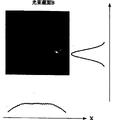
现有技术中都是用两个互相垂直的柱面透镜将出射光束聚焦成一个椭圆形光斑照射到细胞上,照射高斯光束通过一个柱面透镜在X方向上汇聚在流动室2的通孔21处、通过另一个柱面透镜在Y方向上汇聚在流动室2附近。如图2所示,在流动室处的光斑形状是椭圆形,其在Y方向上大约为细胞直径大小,在X方向上大约为流动室2的通孔21内壁尺寸,在X和Y两个方向上的光场分布基本上为高斯分布。In the prior art, two mutually perpendicular cylindrical lenses are used to focus the outgoing beam into an elliptical spot to irradiate the cells, and the irradiated Gaussian beam converges on the through
现有技术采用一组柱面透镜对高斯光束进行聚焦仅仅考虑到照射光斑的尺寸要求,并没有考虑在不同方向上的光强度分布的要求。因为用柱面透镜并不能实现“平顶”(flat-top)分布,所以在X和Y方向上,光强仍然呈高斯分布,那么同类的粒子在从不同的位置通过这个光照射区时就会由于照射到其上的光强度不同而形成不同强度的光散射信号或荧光信号,导致对这个粒子的判断出现错误。上述错误可以用图3和图4来解释,图3给出了照射光斑的形状以及在X方向上光强度分布,同类的粒子A和B从不同的位置进入到光照射区域3中,由于光强分布的不均匀性导致照射到处于光斑中心的粒子A和偏离光斑中心的粒子B上的光能量不相同。如图4所示,这将导致处于光斑中心的粒子A和偏离光斑中心的粒子B各自形成的光散射信号就会不同,分别形成光散射信号A和光散射信号B。后续的分析模块就有可能根据光散射信号将粒子B判断成为不同于粒子A的一类粒子,造成误差。In the prior art, a group of cylindrical lenses is used to focus the Gaussian beam only considering the requirement of the size of the irradiation spot, and does not consider the requirement of the light intensity distribution in different directions. Because the "flat-top" distribution cannot be achieved with a cylindrical lens, the light intensity is still Gaussian in the X and Y directions, and the particles of the same kind pass through the light irradiation area from different positions. Light scattering signals or fluorescence signals of different intensities will be formed due to the different intensities of light irradiated on it, resulting in errors in the judgment of this particle. The above errors can be explained by Figure 3 and Figure 4. Figure 3 shows the shape of the irradiation spot and the light intensity distribution in the X direction. The same kind of particles A and B enter the light irradiation area 3 from different positions. The inhomogeneity of the strong distribution leads to different light energies irradiated on the particle A at the center of the spot and the particle B away from the center of the spot. As shown in FIG. 4 , this will result in different light scattering signals formed by particle A at the center of the light spot and particle B deviated from the center of the light spot, forming light scattering signal A and light scattering signal B respectively. Subsequent analysis modules may judge particle B to be a type of particle different from particle A according to the light scattering signal, causing errors.
发明内容 Contents of the invention
本发明所要解决的技术问题是克服现有技术的不足,提供一种用于基于流式细胞术的仪器的光电传感器,能使照射到细胞上的光束在X方向上实现均匀分布,以消除由于细胞从光照区的不同位置进入而产生的误差。The technical problem to be solved by the present invention is to overcome the deficiencies of the prior art, and to provide a photoelectric sensor for flow cytometry-based instruments, which can make the light beams irradiated on the cells uniformly distributed in the X direction, to eliminate the The error caused by cells entering from different positions in the illuminated area.
本发明所要解决的另一个技术问题是克服现有技术的不足,提供一种用于基于流式细胞术的仪器的光电传感器的照射单元,能使照射到细胞上的光束在X方向上实现均匀分布,以消除由于细胞从光照区的不同位置进入而产生的误差。Another technical problem to be solved by the present invention is to overcome the deficiencies of the prior art and provide an irradiation unit for a photoelectric sensor of an instrument based on flow cytometry, which can make the light beam irradiated on the cells uniform in the X direction. distribution to eliminate errors due to cells entering from different positions in the illuminated area.
本发明的第一个技术问题通过以下的技术方案予以解决:First technical problem of the present invention is solved by following technical scheme:
一种用于基于流式细胞术的仪器的光电传感器,包括照射单元、流动室和光电探测单元;所述照射单元包括用于发出照射光束的光源和用于将照射光束在流动室内形成光照射区的光束聚焦模块;所述流动室用于使细胞流在鞘液的包裹之下逐个地通过光照射区;所述光电探测单元用于收集细胞在通过流动室时经光照射之后发出的光信息并将光信息转换成电信号;所述光源和光束聚焦模块之间还至少设有用于对X方向的光强分布进行平坦化的光束整形器。A photoelectric sensor for an instrument based on flow cytometry, comprising an irradiation unit, a flow chamber and a photoelectric detection unit; The beam focusing module of the area; the flow chamber is used to make the cell flow pass through the light irradiation area one by one under the sheath fluid; the photodetection unit is used to collect the light emitted by the cells after being irradiated by the light when passing through the flow chamber information and convert the optical information into electrical signals; at least a beam shaper for flattening the light intensity distribution in the X direction is provided between the light source and the beam focusing module.
优选地,所述光源为激光光源,包括至少两个发出不同特性的高斯光束的激光器,所述光束整形器是衍射光学元件。Preferably, the light source is a laser light source, including at least two lasers emitting Gaussian beams with different characteristics, and the beam shaper is a diffractive optical element.
所述衍射光学元件为用于对X方向的光强分布进行平坦化的一维衍射光学元件。The diffractive optical element is a one-dimensional diffractive optical element for flattening the light intensity distribution in the X direction.
所述光束整形器的β>=40,所述
所述光束聚焦模块包括在Y方向对光束进行聚焦的聚焦透镜,以及至少两个在X方向进行光束缩放的柱面透镜,所述聚焦透镜的聚焦点在流动室中心。The beam focusing module includes a focusing lens for focusing the beam in the Y direction, and at least two cylindrical lenses for zooming the beam in the X direction, and the focusing point of the focusing lens is at the center of the flow chamber.
所述光束聚焦模块在流动室内形成的光照区域的尺寸在Y方向上和细胞直径相当、在X方向上与流动室通孔的内壁的尺寸相当。The size of the illuminated area formed by the beam focusing module in the flow chamber is equivalent to the diameter of the cell in the Y direction, and is equivalent to the size of the inner wall of the through hole of the flow chamber in the X direction.
本发明的另一个技术问题通过以下的技术方案予以解决:Another technical problem of the present invention is solved by following technical scheme:
一种用于基于流式细胞术的仪器的光电传感器的照射单元,包括用于发出照射光束的光源和用于将照射光束在流动室内形成光照射区的光束聚焦模块,所述光源和光束聚焦模块之间还至少设有用于对X方向的光强分布进行平坦化的光束整形器。An irradiation unit for a photoelectric sensor of an instrument based on flow cytometry, comprising a light source for emitting an irradiation beam and a beam focusing module for forming the irradiation beam into a light irradiation area in a flow chamber, the light source and the beam are focused At least a beam shaper for flattening the light intensity distribution in the X direction is provided between the modules.
优选地,所述光源为激光光源,包括至少两个发出不同特性的高斯光束的激光器,所述光束整形器是衍射光学元件。Preferably, the light source is a laser light source, including at least two lasers emitting Gaussian beams with different characteristics, and the beam shaper is a diffractive optical element.
所述衍射光学元件为用于对X方向的光强分布进行平坦化的一维衍射光学元件。The diffractive optical element is a one-dimensional diffractive optical element for flattening the light intensity distribution in the X direction.
所述光束整形器的β>=40,所述
本发明与现有技术对比的有益效果是:The beneficial effect that the present invention compares with prior art is:
本发明的用于基于流式细胞术的仪器的光电传感器的照射单元,在激光光源和光束聚焦模块之间还设有光束整形器,能够使照射光束在流动室形成在X方向上的强度分布为均匀分布的光照射区,当同一类细胞或粒子从不同位置进入光照射区时会获得强度基本相同的光信号,从而避免后续的分析模块将从不同位置进入光照射区的同一类粒子误判断成为不同类的粒子,避免了误差,提高系统对粒子识别的分辨能力,提高稳定性。本发明的光电传感器大大提高了基于流式细胞术的仪器的稳定性,从而可以大大降低对流体稳定性的要求,降低了基于流式细胞术的仪器的实现难度。The irradiation unit of the photoelectric sensor used in the instrument based on flow cytometry of the present invention is also equipped with a beam shaper between the laser light source and the beam focusing module, which can make the irradiation beam form an intensity distribution in the X direction in the flow chamber It is a uniformly distributed light irradiation area. When the same type of cells or particles enter the light irradiation area from different positions, they will obtain light signals with basically the same intensity, so as to avoid subsequent analysis modules from mistaking the same type of particles entering the light irradiation area from different positions. It is judged to be different types of particles, which avoids errors, improves the system's ability to distinguish particles, and improves stability. The photoelectric sensor of the present invention greatly improves the stability of the instrument based on flow cytometry, thereby greatly reducing the requirement on fluid stability and reducing the difficulty of implementing the instrument based on flow cytometry.
附图说明 Description of drawings
图1a、1b是现有的用于基于流式细胞术的仪器的光电传感器的结构示意图;Figures 1a and 1b are structural schematic diagrams of existing photosensors for flow cytometry-based instruments;
图2是现有的光电传感器形成的照射光斑的形状和光场分布示意图;2 is a schematic diagram of the shape and light field distribution of the irradiation spot formed by the existing photoelectric sensor;
图3是照射光斑的形状以及在X方向上光强度分布示意图;Fig. 3 is a schematic diagram of the shape of the irradiation spot and the light intensity distribution in the X direction;
图4是同样粒子从光照区域的不同位置进入时所形成的光信号示意图;Fig. 4 is a schematic diagram of the optical signal formed when the same particle enters from different positions in the illuminated area;
图5a、5b是本发明一种具体实施方式的结构示意图;5a and 5b are schematic structural views of a specific embodiment of the present invention;
图6a是本发明的光电传感器在整形之前的光束截面的形状和光场分布示意图;Figure 6a is a schematic diagram of the shape and light field distribution of the beam section of the photoelectric sensor of the present invention before shaping;
图6b是本发明的光电传感器在整形之后的光束截面的形状和光场分布示意图;Fig. 6b is a schematic diagram of the shape and light field distribution of the beam section of the photoelectric sensor of the present invention after shaping;
图7是本发明的光电传感器照射到细胞上的光照区域的光强度分布示意图;Fig. 7 is a schematic diagram of the light intensity distribution of the photoelectric sensor of the present invention irradiating the illuminated area on the cell;
图8是使用本发明的光电传感器时同样粒子从光照区域的不同位置进入时所形成的光信号示意图。Fig. 8 is a schematic diagram of light signals formed when the same particle enters from different positions in the illuminated area when the photoelectric sensor of the present invention is used.
具体实施方式 Detailed ways
如图5a、5b所示的用于基于流式细胞术的仪器的光电传感器,包括照射单元1、流动室2和光电探测单元(图中未示出)。所述照射单元1包括依次排列的光源11、光束整形器12和光束聚焦模块13。所述流动室2包括一个细胞流过的通孔21,在这个通孔21中运用流体聚焦原理将细胞包裹在鞘流中。The photoelectric sensor used in the instrument based on flow cytometry as shown in Fig. 5a, 5b includes an
光源11可以是一个发出一种特性高斯光束的激光器,也可以包括至少两个发出不同特性高斯光束的激光器,优选后者。光源11发出的光束为基模高斯光束,在横切面上的强度分布为高斯形圆对称分布,沿z轴传播的高斯光束解析表达式为:The
其中:z轴坐标原点设在光束的腰处,ω0为高斯光束的腰斑半径,f为产生高斯光束的共焦腔参数,也称高斯光束的焦参数。ω0与f存在以下关系:Wherein: the z-axis coordinate origin is set at the waist of the beam, ω 0 is the waist spot radius of the Gaussian beam, and f is the parameter of the confocal cavity that generates the Gaussian beam, also called the focal parameter of the Gaussian beam. ω 0 has the following relationship with f:
其中R(z)、ω(z)分别表示z坐标处高斯光束的等相面曲率半径及等相面上的光斑半径。Among them, R(z) and ω(z) represent the radius of curvature of the isophase surface of the Gaussian beam at the z coordinate and the radius of the spot on the isophase surface, respectively.
所述光束整形器12用于将光源11出射的光束进行整形,使其在X方向上的强度分布为均匀分布。由于整形只针对X方向,所以光束在Y方向上依然是高斯分布。所述光束整形器12可以为非球面镜组或渐变折射率透镜(GRIN)或衍射光学元件。其中衍射光学元件可以同时对多种不同特性的高斯光束同时整形而不影响整形的效果。The
其中衍射光学元件为一维衍射光学元件,只用于对X方向的光场分布进行平坦化,以简化一维衍射光学元件的结构。The diffractive optical element is a one-dimensional diffractive optical element, which is only used to flatten the light field distribution in the X direction, so as to simplify the structure of the one-dimensional diffractive optical element.
图6a给出了光束整形器12对光束整形之前的光束截面A形状和光场分布,如图6a所示,在进入光束整形器12之前,光束的光场在X方向和Y方向上都是高斯分布。图6b给出了光束整形器12对光束整形之后的光束截面B的形状和光场分布。如图6b所示,经过整形后光束在Y方向上的光场仍然是高斯分布,而在X方向上的光场基本上变成了平场。Figure 6a shows the shape of the beam section A and the light field distribution before the
光束聚焦模块13用于在互相垂直的X和Y两个方向上对整形后的光束分别进行压缩,使照射光束在达到流动室2时形成具有特定尺寸的光照射区。所述特定尺寸为:在Y方向上和细胞直径相当、在X方向上与流动室通孔21的内壁的尺寸相当。所述光束聚焦模块13优选为透镜组,所述透镜组的入瞳位置与平场平面一致,出瞳位置即为流动室,也就是真正照射到细胞上的位置。The
所述透镜组包括在X方向进行光束缩放的第一柱面透镜131、第二柱面透镜132,以及在Y方向对光束进行聚焦的一维聚焦透镜133,所述一维聚焦透镜133优选柱面透镜。所述一维聚焦透镜133的聚焦点在流动室中心,以保持X和Y两方向的共焦性。The lens group includes a first
光束整形器的设计受到β因子的约束,
根据测不准原理β应大于0.69,β值越大整形后的分布在边缘的位置越陡峭,但是边缘抖动也越厉害;β值越小,整形后的平场分布效果越差,但是边缘附近的分布较平缓。β值的具体选择范围需要根据系统对平顶范围的大小以及边缘抖动的可接受程度来进行。在流式细胞仪中为了获得较大范围的平场分布,应使β值尽量大,一个效果较好的选择是β>=40。According to the uncertainty principle, β should be greater than 0.69. The larger the value of β, the steeper the distribution at the edge after shaping, but the more severe the edge jitter; the smaller the value of β, the worse the effect of flat field distribution after shaping, but near the edge The distribution is flatter. The specific selection range of the β value needs to be carried out according to the acceptability of the system to the size of the flat-top range and the edge jitter. In order to obtain a wider range of flat field distribution in the flow cytometer, the β value should be as large as possible, and a better choice is β>=40.
在β因子的定义中,ω0与λ为入射光束的特性,是固定值。由于系统结构的约束,d不能够非常小,因此如果要得到较大的β值,必须适当增加整形后的光斑半宽度y0。而根据流式细胞仪的特点,在X方向上的照射光斑的宽度应和流动室的内壁宽度相当,通常情况下流式细胞仪的流动室内壁大约在200~400um之间。使用两个在X方向进行光束缩放的柱面透镜可以使得当光束整形器12的β值较大时,使经过光束整形器整形后的光束在X方向上的照射光斑的尺寸满足流动室内壁尺寸要求。In the definition of the β factor, ω 0 and λ are characteristics of the incident beam and are fixed values. Due to the constraints of the system structure, d cannot be very small, so if a larger β value is to be obtained, the half-width y 0 of the shaped spot must be appropriately increased. According to the characteristics of the flow cytometer, the width of the irradiation spot in the X direction should be equivalent to the width of the inner wall of the flow chamber. Usually, the inner wall of the flow cytometer is about 200-400um. Using two cylindrical lenses for zooming the beam in the X direction can make the size of the irradiation spot of the beam shaped by the beam shaper in the X direction meet the size of the inner wall of the flow chamber when the β value of the
经过光束整形器12整形后的光束在Y方向上的尺寸并没有变化,所述一维聚焦透镜133在Y方向上的光斑尺寸进行压缩,使照射光束在达到流动室中心时,在Y方向上和细胞直径相当。通常情况下细胞直径的大小约为10um左右。由于在Y方向上的光强度分布并不需要均一性,因此在Y方向上光场分布始终是高斯形。The size of the beam in the Y direction after being shaped by the
整形之后的光束在经过上述光束聚焦模块13之后汇聚在流动室中心,其分布如图7所示:在X方向上形成了200um左右的平场分布,在Y方向上形成了10um左右的高斯分布。如图8所示,当同样粒子A和B从X方向上的不同位置进入照射区时域都会得到相同的信号强度,即得到相同幅度的散射信号或者荧光信号。The shaped beam converges at the center of the flow chamber after passing through the above-mentioned
细胞流在鞘液的包裹之下逐个地通过所述流动室2的光照射区,在照射之后形成各种光信息;所述流动室2为光透明材料做成,一般是石英,其通孔21的内壁都是方形或矩形。The cell flow passes through the light irradiation area of the
所述光电探测单元用于收集细胞上发出的光信息并将光信息转换成电信号,可采用现有技术中的各种方式予以实现。所述光电探测单元还可对电信号进行放大,所述光电探测单元通常包括光电二极管、光电倍增管。The photoelectric detection unit is used to collect the light information emitted by the cells and convert the light information into electrical signals, which can be realized in various ways in the prior art. The photodetection unit can also amplify the electrical signal, and the photodetection unit generally includes a photodiode and a photomultiplier tube.
以上内容是结合具体的优选实施方式对本发明所作的进一步详细说明,不能认定本发明的具体实施只局限于这些说明。对于本发明所属技术领域的普通技术人员来说,在不脱离本发明构思的前提下,还可以做出若干简单推演或替换,都应当视为属于本发明的保护范围。The above content is a further detailed description of the present invention in conjunction with specific preferred embodiments, and it cannot be assumed that the specific implementation of the present invention is limited to these descriptions. For those of ordinary skill in the technical field of the present invention, without departing from the concept of the present invention, some simple deduction or replacement can be made, which should be regarded as belonging to the protection scope of the present invention.
Claims (10)


Priority Applications (2)
| Application Number | Priority Date | Filing Date | Title |
|---|---|---|---|
| CN200710073186A CN101236150B (en) | 2007-02-02 | 2007-02-02 | Stream type cell technique instrument opto-electronic sensor and its irradiation unit |
| US11/932,847 US7876436B2 (en) | 2007-02-02 | 2007-10-31 | Irradiation unit for a flow-cytometry-based analytical instrument and analytical instrument including the same |
Applications Claiming Priority (1)
| Application Number | Priority Date | Filing Date | Title |
|---|---|---|---|
| CN200710073186A CN101236150B (en) | 2007-02-02 | 2007-02-02 | Stream type cell technique instrument opto-electronic sensor and its irradiation unit |
Publications (2)
| Publication Number | Publication Date |
|---|---|
| CN101236150A CN101236150A (en) | 2008-08-06 |
| CN101236150B true CN101236150B (en) | 2012-09-05 |
Family
ID=39675864
Family Applications (1)
| Application Number | Title | Priority Date | Filing Date |
|---|---|---|---|
| CN200710073186A Active CN101236150B (en) | 2007-02-02 | 2007-02-02 | Stream type cell technique instrument opto-electronic sensor and its irradiation unit |
Country Status (2)
| Country | Link |
|---|---|
| US (1) | US7876436B2 (en) |
| CN (1) | CN101236150B (en) |
Families Citing this family (25)
| Publication number | Priority date | Publication date | Assignee | Title |
|---|---|---|---|---|
| US8334976B2 (en) | 2008-03-18 | 2012-12-18 | The Board Of Trustees Of The University Of Illinois | Second-order nonlinear susceptibility of a nanoparticle using coherent confocal microscopy |
| US8045161B2 (en) * | 2008-03-18 | 2011-10-25 | The Board Of Trustees Of The University Of Illinois | Robust determination of the anisotropic polarizability of nanoparticles using coherent confocal microscopy |
| JP5534214B2 (en) * | 2009-10-05 | 2014-06-25 | ベイバイオサイエンス株式会社 | Flow cytometer and flow cytometry method |
| JP5537347B2 (en) * | 2009-11-30 | 2014-07-02 | シスメックス株式会社 | Particle analyzer |
| KR20120036230A (en) * | 2010-10-07 | 2012-04-17 | 삼성전자주식회사 | Fluorescence detecting optical system and multi-channel fluorescence detection apparatus having the same |
| PT2699264T (en) | 2011-04-20 | 2018-05-23 | Medimmune Llc | ANTIBODIES AND OTHER MOLECULES CONNECTING B7-H1 AND PD-1 |
| EP2786117B1 (en) * | 2011-12-01 | 2022-12-21 | Particle Measuring Systems, Inc. | Detection scheme for particle size and concentration measurement |
| WO2013101675A2 (en) | 2011-12-29 | 2013-07-04 | Abbott Laboratories | Flow cytometry systems and methods for blocking diffraction patterns |
| US9746412B2 (en) | 2012-05-30 | 2017-08-29 | Iris International, Inc. | Flow cytometer |
| JP2015525343A (en) * | 2012-05-30 | 2015-09-03 | アイリス インターナショナル インコーポレイテッド | Flow cytometer |
| EP3869181A1 (en) * | 2013-03-14 | 2021-08-25 | Abbott Laboratories | Beam shaping optics of flow cytometer systems and methods related thereto |
| CN103293089A (en) * | 2013-06-13 | 2013-09-11 | 长春迪瑞医疗科技股份有限公司 | Reticulocyte analyzer |
| DE102013216362A1 (en) * | 2013-08-19 | 2015-02-19 | Siemens Healthcare Diagnostics Products Gmbh | Analysis method for classification support |
| CN104502255B (en) * | 2014-12-29 | 2017-04-05 | 中国科学院长春光学精密机械与物理研究所 | Three-dimensional imaging flow cytometry device |
| CN105181561B (en) * | 2015-09-02 | 2018-04-24 | 江苏大学 | A kind of blood cell analysis sensor |
| CN109374511B (en) * | 2015-10-14 | 2021-07-23 | 北京信息科技大学 | An optical path adjustment device for flow cytometer without liquid path |
| GB201609017D0 (en) * | 2016-05-23 | 2016-07-06 | Isis Innovation | Characterisation of particles |
| WO2019191419A2 (en) * | 2018-03-30 | 2019-10-03 | Idexx Laboratories, Inc. | Flow cytometer, laser optics assembly thereof, and methods of assembling the same |
| CN109357992B (en) * | 2018-11-09 | 2021-11-02 | 赛默飞世尔(上海)仪器有限公司 | Optical system and flow cytometer for beam shaping |
| CN111258076A (en) * | 2018-11-30 | 2020-06-09 | 福州高意光学有限公司 | Optical system capable of realizing laser beam homogenization function |
| EP4062153B1 (en) * | 2019-11-22 | 2023-08-23 | ams AG | Optical based particulate matter sensing |
| JP7420551B2 (en) * | 2019-12-27 | 2024-01-23 | リオン株式会社 | particle measuring device |
| EP4168773B1 (en) | 2020-06-17 | 2024-07-17 | Idexx Laboratories, Inc. | Flow cytometer and laser optics assembly thereof |
| CN116106524B (en) * | 2023-04-11 | 2023-08-25 | 深圳市帝迈生物技术有限公司 | blood analysis device |
| CN119290716A (en) * | 2024-11-01 | 2025-01-10 | 中国科学院空天信息创新研究院 | Single-cell protein quantitative detection system and method based on diffractive optical elements |
Citations (3)
| Publication number | Priority date | Publication date | Assignee | Title |
|---|---|---|---|---|
| US4327972A (en) * | 1979-10-22 | 1982-05-04 | Coulter Electronics, Inc. | Redirecting surface for desired intensity profile |
| US5331468A (en) * | 1992-11-27 | 1994-07-19 | Eastman Kodak Company | Intensity redistribution for exposure correction in an overfilled symmetrical laser printer |
| US5999256A (en) * | 1992-02-12 | 1999-12-07 | Cambridge Consultants Limited | Particle measurement system |
Family Cites Families (13)
| Publication number | Priority date | Publication date | Assignee | Title |
|---|---|---|---|---|
| US3476463A (en) * | 1965-05-11 | 1969-11-04 | Perkin Elmer Corp | Coherent light optical system yielding an output beam of desired intensity distribution at a desired equiphase surface |
| US4850707A (en) * | 1986-06-06 | 1989-07-25 | Massachusetts Institute Of Technology | Optical pulse particle size analyzer |
| JPH0240535A (en) * | 1988-07-30 | 1990-02-09 | Horiba Ltd | Partial measuring type fine particle counter |
| NL8903013A (en) | 1989-11-02 | 1991-06-03 | Philips Nv | GRID OBJECTIVE AND GRID BUNDLE CONVERTER AND OPTICAL SCANNER EQUIPPED WITH AT LEAST ONE OF THESE ELEMENTS. |
| US6741344B1 (en) * | 1994-02-10 | 2004-05-25 | Affymetrix, Inc. | Method and apparatus for detection of fluorescently labeled materials |
| US5891734A (en) * | 1994-08-01 | 1999-04-06 | Abbott Laboratories | Method for performing automated analysis |
| JP3375203B2 (en) | 1994-08-08 | 2003-02-10 | シスメックス株式会社 | Cell analyzer |
| CA2227771A1 (en) | 1995-08-21 | 1997-02-27 | Imperial Chemical Industries Plc | Polyisocyanate particles of controlled particle size and particle size distribution |
| JP4323571B2 (en) * | 1997-01-31 | 2009-09-02 | エックスワイ, インコーポレイテッド | Optical device |
| CN1088924C (en) | 1998-01-24 | 2002-08-07 | 鸿海精密工业股份有限公司 | Electronic card connector |
| US6961200B2 (en) * | 1999-07-27 | 2005-11-01 | Quantum Corporation | Optical servo track identification on tape storage media |
| CA2451325A1 (en) | 2001-07-16 | 2003-02-06 | Jari Turunen | Diffractive shaping of the intensity distribution of a spatially partially coherent light beam |
| US20060192940A1 (en) * | 2005-01-20 | 2006-08-31 | Phi-Wilson Janette T | Modular flow cytometry system |
-
2007
- 2007-02-02 CN CN200710073186A patent/CN101236150B/en active Active
- 2007-10-31 US US11/932,847 patent/US7876436B2/en active Active
Patent Citations (3)
| Publication number | Priority date | Publication date | Assignee | Title |
|---|---|---|---|---|
| US4327972A (en) * | 1979-10-22 | 1982-05-04 | Coulter Electronics, Inc. | Redirecting surface for desired intensity profile |
| US5999256A (en) * | 1992-02-12 | 1999-12-07 | Cambridge Consultants Limited | Particle measurement system |
| US5331468A (en) * | 1992-11-27 | 1994-07-19 | Eastman Kodak Company | Intensity redistribution for exposure correction in an overfilled symmetrical laser printer |
Also Published As
| Publication number | Publication date |
|---|---|
| US7876436B2 (en) | 2011-01-25 |
| CN101236150A (en) | 2008-08-06 |
| US20080186490A1 (en) | 2008-08-07 |
Similar Documents
| Publication | Publication Date | Title |
|---|---|---|
| CN101236150B (en) | Stream type cell technique instrument opto-electronic sensor and its irradiation unit | |
| US7075647B2 (en) | Back-scatter detection in flow cytometers | |
| CN101153868B (en) | Stream type cell analyzer | |
| US6713019B2 (en) | Flow cytometer | |
| EP2977744B1 (en) | Flow cytometer, particle analyzer, and flow cytometric method | |
| CN106019608B (en) | One type Gauss flat top beam laser system | |
| CN208206768U (en) | Optical system | |
| US20250277732A1 (en) | Light collection from objects within a fluid column | |
| JP2021503608A (en) | Optical flow cytometer for epifluorescence measurement | |
| CN109357992B (en) | Optical system and flow cytometer for beam shaping | |
| CN113008768B (en) | Reflective fluorescence collection device for flow cytometry | |
| CN111024592A (en) | Flow cytometer optical device | |
| CN112596250A (en) | Illumination system of flow cytometry sorter and flow cytometry sorter | |
| CN103245643A (en) | Optical system for fluorescence detection and fine particle analyzing apparatus | |
| CN211856293U (en) | Flow cytometer optical device | |
| JP4763159B2 (en) | Flow cytometer | |
| CN206178259U (en) | Class gauss flat top beam laser system | |
| CN216117256U (en) | Linear light spot light path structure based on motion optical test | |
| CN117740654A (en) | Optical collection system for flow cytometry | |
| JPS61182549A (en) | Flow cell | |
| CN116067864A (en) | Optical system of flow cytometer and flow cytometer |
Legal Events
| Date | Code | Title | Description |
|---|---|---|---|
| C06 | Publication | ||
| PB01 | Publication | ||
| C10 | Entry into substantive examination | ||
| SE01 | Entry into force of request for substantive examination | ||
| ASS | Succession or assignment of patent right |
Owner name: BEIJING SHEN MINDRAY MEDICAL ELECTRONICS TECHNOLOG Effective date: 20110830 |
|
| C41 | Transfer of patent application or patent right or utility model | ||
| COR | Change of bibliographic data |
Free format text: CORRECT: ADDRESS; FROM: 518057 SHENZHEN, GUANGDONG PROVINCE TO: 100085 HAIDIAN, BEIJING |
|
| TA01 | Transfer of patent application right |
Effective date of registration: 20110830 Address after: No. 8 Beijing Haidian District Qunying Science Park 100085 information industry base on the entrepreneurial road No. 5 building three layer Applicant after: Beijing Shenmairui Medical Electronic Technology Research Institute Co., Ltd. Address before: 518057 Nanshan District science and Technology Industrial Park, Guangdong, Zhejiang Province, road, MINDRAY Applicant before: Shenzhen Mairui Biotherapeutic Electronic Co., Ltd. |
|
| ASS | Succession or assignment of patent right |
Owner name: SHENZHEN MAIRUI BIOTHERAPEUTIC ELECTRONIC CO. LTD. Free format text: FORMER OWNER: BEIJING SHENMAIRUI MEDICAL AND ELECTRONIC TECHNOLOGY RESEARCH INSTITUTE CO., LTD. Effective date: 20120614 Owner name: BEIJING SHENMAIRUI MEDICAL AND ELECTRONIC TECHNOLO Effective date: 20120614 |
|
| C41 | Transfer of patent application or patent right or utility model | ||
| COR | Change of bibliographic data |
Free format text: CORRECT: ADDRESS; FROM: 100085 HAIDIAN, BEIJING TO: 518057 SHENZHEN, GUANGDONG PROVINCE |
|
| TA01 | Transfer of patent application right |
Effective date of registration: 20120614 Address after: 518057 MINDRAY building, twelve South tech Road, Nanshan District hi tech Industrial Park, Shenzhen, Shenzhen, Guangdong Applicant after: Shenzhen Mairui Biotherapeutic Electronic Co., Ltd. Co-applicant after: Beijing Shenmairui Medical Electronic Technology Research Institute Co., Ltd. Address before: No. 8 Beijing Haidian District Qunying Science Park 100085 information industry base on the entrepreneurial road No. 5 building three layer Applicant before: Beijing Shenmairui Medical Electronic Technology Research Institute Co., Ltd. |
|
| C14 | Grant of patent or utility model | ||
| GR01 | Patent grant |