CN101094588B - Detection fixture - Google Patents
Detection fixture Download PDFInfo
- Publication number
- CN101094588B CN101094588B CN2006100612446A CN200610061244A CN101094588B CN 101094588 B CN101094588 B CN 101094588B CN 2006100612446 A CN2006100612446 A CN 2006100612446A CN 200610061244 A CN200610061244 A CN 200610061244A CN 101094588 B CN101094588 B CN 101094588B
- Authority
- CN
- China
- Prior art keywords
- pin
- hole
- detection tool
- plate
- workpiece
- Prior art date
- Legal status (The legal status is an assumption and is not a legal conclusion. Google has not performed a legal analysis and makes no representation as to the accuracy of the status listed.)
- Expired - Fee Related
Links
Images


Classifications
-
- G—PHYSICS
- G01—MEASURING; TESTING
- G01B—MEASURING LENGTH, THICKNESS OR SIMILAR LINEAR DIMENSIONS; MEASURING ANGLES; MEASURING AREAS; MEASURING IRREGULARITIES OF SURFACES OR CONTOURS
- G01B11/00—Measuring arrangements characterised by the use of optical techniques
- G01B11/02—Measuring arrangements characterised by the use of optical techniques for measuring length, width or thickness
- G01B11/06—Measuring arrangements characterised by the use of optical techniques for measuring length, width or thickness for measuring thickness ; e.g. of sheet material
- G01B11/0691—Measuring arrangements characterised by the use of optical techniques for measuring length, width or thickness for measuring thickness ; e.g. of sheet material of objects while moving
Landscapes
- Physics & Mathematics (AREA)
- General Physics & Mathematics (AREA)
- Testing Electric Properties And Detecting Electric Faults (AREA)
- Tests Of Electronic Circuits (AREA)
- Length Measuring Devices With Unspecified Measuring Means (AREA)
Abstract
一种检测治具,用于检测工件的孔位,该检测治具包括一定位基座、一测量销板及一驱动装置;其中,该定位基座用于定位待检测工件,该测量销板上设有探测销及容置所述探测销的销孔,所述探测销包括一销柱及一设于该销柱一端的探针,该销柱的一端固接有一螺栓,另一端具有一挡止部,所述销柱的一部分可滑动地容置于销孔中,其具有该螺栓及该挡止部的两端伸出该销孔,所述探测销用于探测待检测工件的孔位;该驱动装置用于驱动测量销板移动以探测该定位基座上的待检测工件的孔位。
A testing fixture for detecting the hole positions of a workpiece includes a positioning base, a measuring pin plate, and a driving device. The positioning base positions the workpiece to be tested. The measuring pin plate has a probe pin and a pin hole for accommodating the probe pin. The probe pin includes a pin post and a probe at one end of the pin post. A bolt is fixed to one end of the pin post, and a stop portion is provided at the other end. A portion of the pin post is slidably accommodated in the pin hole, with both ends having the bolt and the stop portion extending out of the pin hole. The probe pin is used to detect the hole positions of the workpiece to be tested. The driving device drives the measuring pin plate to move to detect the hole positions of the workpiece on the positioning base.
Description
技术领域technical field
本发明是关于一种检测治具,尤其关于一种检测工件的孔位的检测治具。The invention relates to a detection jig, in particular to a detection jig for detecting the hole position of a workpiece.
背景技术Background technique
便携式电子装置外壳由于组装上的需要,通常具有许多螺丝孔。例如,笔记本电脑的上下壳体上具有10~40个螺丝孔。所述上下壳体的螺丝孔的孔位精度要求较高,即上下壳体的螺丝孔的位置需要相互精确的匹配,或与其他零组件精确对位。因此,在壳体组装前,需要专门的设备检测壳体上的螺丝孔的位置是否精准。The casing of the portable electronic device usually has many screw holes due to assembly requirements. For example, there are 10-40 screw holes on the upper and lower casings of the notebook computer. The hole position accuracy of the screw holes of the upper and lower shells is required to be high, that is, the positions of the screw holes of the upper and lower shells need to be precisely matched with each other, or precisely aligned with other components. Therefore, before the housing is assembled, special equipment is required to detect whether the positions of the screw holes on the housing are accurate.
所述壳体上的螺丝孔的孔径较小,一般为2mm或小于2mm,现有技术中检测上述螺丝孔的位置的精确度,常使用的设备为三次元影像检测设备,但三次元影像检测设备不能满足小尺寸的螺丝孔的检测精度,且三次元影像检测设备的检测速度受限于其影像扫描速度,使得壳体上的螺丝孔的孔位的量测不能满足工业上快速制造的要求。The hole diameter of the screw hole on the housing is small, generally 2 mm or less. In the prior art, to detect the accuracy of the position of the screw hole, the commonly used equipment is a three-dimensional image detection device, but the three-dimensional image detection The equipment cannot meet the detection accuracy of small-sized screw holes, and the detection speed of the three-dimensional image detection equipment is limited by its image scanning speed, so that the measurement of the hole positions of the screw holes on the shell cannot meet the requirements of rapid industrial manufacturing .
发明内容Contents of the invention
鉴于上述状况,有必要提供一种结构简单,可快速量测工件孔位的检测治具。In view of the above situation, it is necessary to provide a detection fixture with a simple structure that can quickly measure the hole position of the workpiece.
一种检测治具,用于检测工件的孔位,该检测治具包括一定位基座、一测量销板及一驱动装置;其中,该定位基座用于定位待检测工件,该测量销板上设有探测销及容置所述探测销的销孔,所述探测销包括一销柱及一设于该销柱一端的探针,该销柱的一端固接有一螺栓,另一端具有一挡止部,所述销柱的一部分可滑动地容置于销孔中,其具有该螺栓及该挡止部的两端伸出该销孔,所述探测销用于探测待检测工件的孔位;该驱动装置用于驱动测量销板移动以探测该定位基座上的待检测工件的孔位。A detection jig is used to detect the hole position of a workpiece. The detection jig includes a positioning base, a measuring pin plate and a driving device; wherein, the positioning base is used to position the workpiece to be detected, and the measuring pin plate A detection pin and a pin hole for accommodating the detection pin are provided on it, and the detection pin includes a pin and a probe provided at one end of the pin, one end of the pin is fixedly connected with a bolt, and the other end has a A stop part, a part of the pin is slidably accommodated in the pin hole, which has the bolt and two ends of the stop part protruding from the pin hole, and the detection pin is used to detect the hole of the workpiece to be detected position; the driving device is used to drive the measuring pin plate to move to detect the hole position of the workpiece to be detected on the positioning base.
相较现有的技术,本发明所述的检测治具采用探测销检测工件的孔位,具有快速检测工件孔位的优点。Compared with the existing technology, the detection jig of the present invention uses the detection pin to detect the hole position of the workpiece, and has the advantage of quickly detecting the hole position of the workpiece.
附图说明Description of drawings
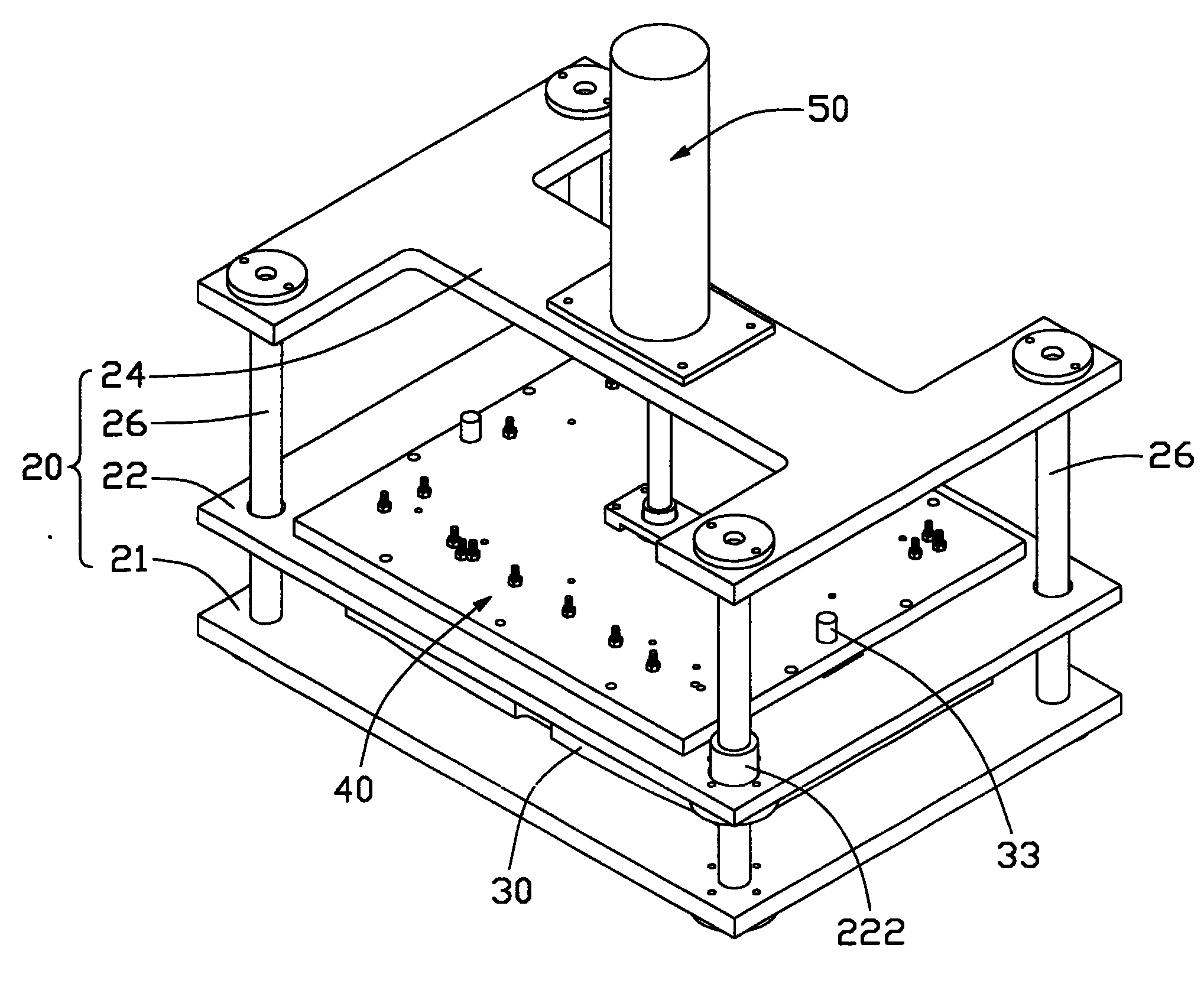
图1是本发明较佳实施方式所述的检测治具立体示意图;Fig. 1 is a three-dimensional schematic diagram of a detection fixture described in a preferred embodiment of the present invention;
图2是本发明较佳实施方式所述的检测治具的分解示意图;Fig. 2 is an exploded schematic view of the detection fixture described in a preferred embodiment of the present invention;
图3是本发明较佳实施方式所述的检测治具的测量销板的另一角度的示意图;Fig. 3 is a schematic diagram of another angle of the measuring pin plate of the testing fixture described in a preferred embodiment of the present invention;
图4是图3中IV处的放大示意图;Fig. 4 is the enlarged schematic diagram of place IV in Fig. 3;
图5是本发明较佳实施方式所述的检测治具的工作状态示意图;Fig. 5 is a schematic diagram of the working state of the detection fixture described in the preferred embodiment of the present invention;
图6是图5中VI处的放大示意图;Fig. 6 is the enlarged schematic diagram of VI place in Fig. 5;
图7是本发明另一实施方式所述的检测治具的示意图;Fig. 7 is a schematic diagram of a detection fixture according to another embodiment of the present invention;
图8是图7中VIII处的放大示意图。FIG. 8 is an enlarged schematic view of VIII in FIG. 7 .
具体实施方式Detailed ways
请同时参照图1及图2所示,本发明较佳实施方式所述的检测治具包括一悬架20、一定位基座30、一测量销板40及一驱动系统50。Please refer to FIG. 1 and FIG. 2 at the same time. The testing fixture according to the preferred embodiment of the present invention includes a
悬架20包括一底板21、一滑动板22及一顶板24。底板21的一表面垂直地固接有四个导柱26。滑动板22上开设有一贯通其上下表面的容置腔220,用于容置测量销板40。滑动板22相对于所述导柱26开设有四个导孔221,所述导柱26穿过所述导孔221,使得滑动板22可沿所述导柱26滑动。为使滑动板22的滑动更为顺畅、平稳,滑动板22的导孔221上还可以分别固接有导滑套222,本实施方式中,选择所述导孔221中的两个固接有导滑套222,导滑套222可滑动的套设于所述导柱26上。顶板24用于承载驱动系统50,其固接于所述导柱26远离底板21的一端。由此,底板21、滑动板22及顶板24沿所述导柱26构成相间隔的层叠式结构。The
定位基座30具有与标准工件(图未示)相匹配的型面31,型面31上设有定位销32,其与所述标准工件的基准孔位相对应,用于定位及固持待检测工件。此外,型面31两端还分别设有一导正销33,用于校正定位基座30与测量销板40的相对位置。定位基座30固定于底板21上。The
请同时参照图3及图4所示,测量销板40包括一基板42、多个探测销44及多个平衡压头46。基板42上开设有多个销孔424及多个螺纹孔426,所述销孔424用于容置所述探测销44,所述螺纹孔426用于固持平衡压头46。所述销孔424依照所述标准工件的螺丝孔的孔位排布,使所述销孔424与所述标准工件的螺丝孔一一对应。此外,基板42上对应于定位基座30上的校正销33的位置上开设有校位孔428,校位孔428与校正销33相配合,以此校正基板42与定位基座30的相对位置。Please refer to FIG. 3 and FIG. 4 at the same time, the
每一探测销44包括一销柱440、一第一弹簧442及一探针444。销柱440的形状、大小与销孔424相匹配,其一端固接有一螺栓446,另一端具有一挡止部448。挡止部448沿销柱440的外周缘突出,使得销柱440具有挡止部448的一端呈台阶状。销柱440的一部分可滑动的容置于销孔424中,其具有螺栓446及挡止部448的两端伸出于销孔424。第一弹簧442套设于销柱440上,其一端抵持于基板42,另一端抵持于挡止部448。探针444与所述标准工件的螺丝孔的尺寸相对应,其设于销柱440具有挡止部448的一端。Each
每一平衡压头46包括一悬持柱460、一压头462、一第二弹簧464及一挡止块466。悬持柱460一端具有与螺纹孔426相匹配的螺纹,其另一端与挡止块466固定连接,其中,挡止块466的外径大于悬持柱460的外径。压头462为筒形体,其沿轴向具有一第一空腔4621及一第二空腔4622,第一空腔4621与第二空腔4622相通,第二空腔4622的外径大于第一空腔4621的外径。悬持柱460的一端从第一空腔4621穿设而出后,固接于螺纹孔426中,另一端固接有挡止块466而容置于第二空腔4622中。第二弹簧464套设于悬持柱460上,其一端抵持于基板42,另一端抵持于压头462。Each
所述探测销44及平衡压头46穿过滑动板22的容置腔220而伸向底板21。基板42两端搭接于滑动板22上,且与滑动板22固定连接。The
请参照图5所示,驱动系统51为气压驱动装置,其包括一气压缸51及一传动轴52。气压缸51固持于顶板24上,传动轴52一端连接于气压缸51,另一端连接于基板42,以驱动基板42及与基板42固接的滑动板22沿一既定路径移动。其中,气压缸51也可由其他类型的驱动装置替代,如液压缸、电动马达等。Please refer to FIG. 5 , the
请同时参照图5及图6所示,所述检测治具工作时,待检测工件90定位于定位基座30上。启动驱动系统50,以驱动测量销板40及滑动板22沿导柱26向下滑动至一预定位置。平衡压头46的压头462抵持工件90,使工件90受力均匀,防止工件变形,也可使工件90变形的部分得以展平。Please refer to FIG. 5 and FIG. 6 at the same time. When the detection jig works, the
当待检测工件90上的螺丝孔92的孔位与所述标准工件的相对应的螺丝孔的孔位一致时,探针444进入螺丝孔92中。当待检测工件90上的螺丝孔92的孔位与所述标准工件的螺丝孔的孔位不一致时,探针444不能进入螺丝孔92中,探测销44则被顶出。因此,所述检测治具工作时,可通过探测销44是否被顶出而判断螺丝孔92的孔位是否满足精度要求。When the position of the
请同时参照图7及图8所示,可以理解的,所述检测治具还可包括一感测装置60。感测装置60安装于销板22上,其可为红外线感测器,包括一发射头61及一接收头62,发射头61、接收头62及探测销44具有螺栓446的一端沿直线设置于销板22。当探测销44未被顶出时,探测销44不影响发射头61及接收头62之间的红外线传播路径,接收头62正常接收发射头61发射的红外线信号;当探测销44被顶出时,其被顶出的部分切断发射头61及接收头62之间的红外线传播路径,接收头62不能接收发射头61发射的红外线信号。感测装置60电连接至一控制系统70,所述控制系统70依接收头62接收的红外线信号判断探测销44是否被顶出,进而判断螺丝孔92的孔位是否满足精度要求。此外,控制系统70也可电连接驱动系统50,以控制驱动系统50的操作。Please refer to FIG. 7 and FIG. 8 at the same time. It can be understood that the detection fixture may further include a
Claims (11)
Priority Applications (2)
| Application Number | Priority Date | Filing Date | Title |
|---|---|---|---|
| CN2006100612446A CN101094588B (en) | 2006-06-21 | 2006-06-21 | Detection fixture |
| US11/682,764 US7663359B2 (en) | 2006-06-21 | 2007-03-06 | Testing mechanism for casings |
Applications Claiming Priority (1)
| Application Number | Priority Date | Filing Date | Title |
|---|---|---|---|
| CN2006100612446A CN101094588B (en) | 2006-06-21 | 2006-06-21 | Detection fixture |
Publications (2)
| Publication Number | Publication Date |
|---|---|
| CN101094588A CN101094588A (en) | 2007-12-26 |
| CN101094588B true CN101094588B (en) | 2010-09-29 |
Family
ID=38872257
Family Applications (1)
| Application Number | Title | Priority Date | Filing Date |
|---|---|---|---|
| CN2006100612446A Expired - Fee Related CN101094588B (en) | 2006-06-21 | 2006-06-21 | Detection fixture |
Country Status (2)
| Country | Link |
|---|---|
| US (1) | US7663359B2 (en) |
| CN (1) | CN101094588B (en) |
Families Citing this family (18)
| Publication number | Priority date | Publication date | Assignee | Title |
|---|---|---|---|---|
| CN101634683B (en) * | 2008-07-25 | 2012-11-21 | 深圳富泰宏精密工业有限公司 | Testing module |
| CN101900522A (en) * | 2009-05-25 | 2010-12-01 | 鸿富锦精密工业(深圳)有限公司 | Detection device for distance between centers of two holes |
| CN101907434A (en) * | 2009-06-02 | 2010-12-08 | 鸿富锦精密工业(深圳)有限公司 | Device for detecting distance between edge and hole |
| US8451120B2 (en) * | 2009-08-14 | 2013-05-28 | Accenture Global Services Limited | System for relative positioning of access points in a real time locating system |
| US8330605B2 (en) | 2009-08-14 | 2012-12-11 | Accenture Global Services Limited | System for providing real time locating and gas exposure monitoring |
| CN102236197B (en) * | 2010-04-23 | 2013-01-30 | 旺宏电子股份有限公司 | a calibration tool |
| CN102445128B (en) * | 2011-10-12 | 2014-01-22 | 奇瑞汽车股份有限公司 | Mechanism for quickly withdrawing detection pin |
| CN102506642A (en) * | 2011-11-21 | 2012-06-20 | 吴江市双精轴承有限公司 | Anti-swivel detecting gauge |
| CN102692168B (en) * | 2012-06-06 | 2014-12-17 | 芜湖永裕汽车工业有限公司 | Device and method for detecting position degree of valve guide pipe holes of cylinder cover of engine |
| CN104048586B (en) * | 2013-03-13 | 2017-05-17 | 赛恩倍吉科技顾问(深圳)有限公司 | Coaxiality detection apparatus |
| CN106197191A (en) * | 2016-06-29 | 2016-12-07 | 中信戴卡股份有限公司 | A kind of knuckle comprehensive check tool |
| CN106441009B (en) * | 2016-11-30 | 2019-08-23 | 江苏南瑞帕威尔电气有限公司 | A kind of multiple function opens component test tooling |
| CN106482610A (en) * | 2016-12-06 | 2017-03-08 | 无锡市创恒机械有限公司 | A kind of concentric press fit device |
| CN107097175B (en) * | 2017-06-21 | 2020-05-19 | 宇龙计算机通信科技(深圳)有限公司 | Disassembling jig and using method thereof |
| CN108106513A (en) * | 2017-12-27 | 2018-06-01 | 苏州塔比诺机电有限公司 | A kind of gauge of corner brace punching detection |
| CN114113965B (en) * | 2021-11-25 | 2024-05-24 | 扬州扬杰电子科技股份有限公司 | High-efficiency testing device for multi-specification electronic packaging products |
| CN114345733B (en) * | 2022-03-15 | 2022-05-13 | 常州德匠数控科技有限公司 | Three-dimensional action detection device and detection method based on artificial intelligence |
| CN115235311A (en) * | 2022-07-28 | 2022-10-25 | 重庆长安汽车股份有限公司 | A power output terminal space size detection tool |
Citations (5)
| Publication number | Priority date | Publication date | Assignee | Title |
|---|---|---|---|---|
| CN85105122B (en) * | 1985-07-05 | 1988-02-17 | Rca公司 | Apparatus and methods for motion tracking |
| CN2092099U (en) * | 1991-04-28 | 1992-01-01 | 朝阳市建筑工程质量监督检测中心 | Pile hole detector |
| CN2201655Y (en) * | 1994-06-22 | 1995-06-21 | 潘金珠 | Orifice plate calibrating device |
| CN2716800Y (en) * | 2004-07-19 | 2005-08-10 | 上海皮尔博格有色零部件有限公司 | An apparatus for detecting hole set position degree common difference |
| CN2718583Y (en) * | 2004-07-15 | 2005-08-17 | 李小智 | Detecting constructional element |
Family Cites Families (2)
| Publication number | Priority date | Publication date | Assignee | Title |
|---|---|---|---|---|
| US5500605A (en) * | 1993-09-17 | 1996-03-19 | At&T Corp. | Electrical test apparatus and method |
| US6359452B1 (en) * | 1998-07-22 | 2002-03-19 | Nortel Networks Limited | Method and apparatus for testing an electronic assembly |
-
2006
- 2006-06-21 CN CN2006100612446A patent/CN101094588B/en not_active Expired - Fee Related
-
2007
- 2007-03-06 US US11/682,764 patent/US7663359B2/en not_active Expired - Fee Related
Patent Citations (5)
| Publication number | Priority date | Publication date | Assignee | Title |
|---|---|---|---|---|
| CN85105122B (en) * | 1985-07-05 | 1988-02-17 | Rca公司 | Apparatus and methods for motion tracking |
| CN2092099U (en) * | 1991-04-28 | 1992-01-01 | 朝阳市建筑工程质量监督检测中心 | Pile hole detector |
| CN2201655Y (en) * | 1994-06-22 | 1995-06-21 | 潘金珠 | Orifice plate calibrating device |
| CN2718583Y (en) * | 2004-07-15 | 2005-08-17 | 李小智 | Detecting constructional element |
| CN2716800Y (en) * | 2004-07-19 | 2005-08-10 | 上海皮尔博格有色零部件有限公司 | An apparatus for detecting hole set position degree common difference |
Non-Patent Citations (2)
| Title |
|---|
| CN 2092099 U,全文. |
| JP特开2004-244814A 2004.09.02 |
Also Published As
| Publication number | Publication date |
|---|---|
| US20070294899A1 (en) | 2007-12-27 |
| CN101094588A (en) | 2007-12-26 |
| US7663359B2 (en) | 2010-02-16 |
Similar Documents
| Publication | Publication Date | Title |
|---|---|---|
| CN101094588B (en) | Detection fixture | |
| US10132733B2 (en) | Universal mechanical tester for measuring friction and wear characteristics of materials | |
| US9581533B2 (en) | Modular hardness testing machine | |
| US7343764B2 (en) | Placing tool with means for controlling placing processes | |
| CN101551233B (en) | Workpiece size detecting device | |
| US4862598A (en) | Quick connect/disconnect repeatable sensor mounting apparatus | |
| TW201445108A (en) | Wall thickness measurer | |
| JP7353831B2 (en) | Inner diameter measuring device and inner diameter measuring method using the inner diameter measuring device | |
| CN104316408A (en) | Comprehensive carton paperboard tester | |
| EP2009388B1 (en) | Device for checking countersink dimensions | |
| US11353312B2 (en) | Roughness tester | |
| CN1829896A (en) | Roughness measuring device with measurement standard | |
| CN114020555B (en) | A robot end detection device with vision for internal inspection of chassis | |
| CN113933160A (en) | Biaxial tension test machine | |
| US20170148351A1 (en) | Smart drill guide device for muscle training of hand drilling operations | |
| JP2024152529A (en) | Automatic measurement system and method for controlling the automatic measurement system | |
| KR101727504B1 (en) | Apparatus for Portable Verifying Tester of Measuring Instrument having Radiation Shield | |
| CN210180310U (en) | Fine adjustment go-no go gauge device | |
| KR100722225B1 (en) | Inspection device | |
| CN219694423U (en) | Calibration test board for steering engine sensor | |
| EP3736527B1 (en) | Surface shape measurement device | |
| CN118009867A (en) | Stepped sleeve inner diameter detection device | |
| CN210533229U (en) | Motor shaft extension size detection device | |
| CN212931291U (en) | Roundness detection device | |
| CN215985083U (en) | Spring top post of fan detection jig and fan detection jig |
Legal Events
| Date | Code | Title | Description |
|---|---|---|---|
| C06 | Publication | ||
| PB01 | Publication | ||
| C10 | Entry into substantive examination | ||
| SE01 | Entry into force of request for substantive examination | ||
| C14 | Grant of patent or utility model | ||
| GR01 | Patent grant | ||
| CF01 | Termination of patent right due to non-payment of annual fee |
Granted publication date: 20100929 Termination date: 20150621 |
|
| EXPY | Termination of patent right or utility model |