CN101011252B - Focus/detector system of an X-ray apparatus for generating phase contrast recordings - Google Patents
Focus/detector system of an X-ray apparatus for generating phase contrast recordings Download PDFInfo
- Publication number
- CN101011252B CN101011252B CN2007100079530A CN200710007953A CN101011252B CN 101011252 B CN101011252 B CN 101011252B CN 2007100079530 A CN2007100079530 A CN 2007100079530A CN 200710007953 A CN200710007953 A CN 200710007953A CN 101011252 B CN101011252 B CN 101011252B
- Authority
- CN
- China
- Prior art keywords
- grating
- ray
- detector
- phase
- focus
- Prior art date
- Legal status (The legal status is an assumption and is not a legal conclusion. Google has not performed a legal analysis and makes no representation as to the accuracy of the status listed.)
- Expired - Fee Related
Links
- 238000001514 detection method Methods 0.000 claims abstract description 67
- 230000005855 radiation Effects 0.000 claims abstract description 25
- 238000000034 method Methods 0.000 claims abstract description 21
- 230000010363 phase shift Effects 0.000 claims description 47
- 239000008186 active pharmaceutical agent Substances 0.000 claims description 32
- 238000004458 analytical method Methods 0.000 claims description 31
- 238000005259 measurement Methods 0.000 claims description 31
- 238000007689 inspection Methods 0.000 claims description 10
- 238000003325 tomography Methods 0.000 claims description 9
- 239000000463 material Substances 0.000 claims description 8
- 230000005540 biological transmission Effects 0.000 claims description 4
- 238000006243 chemical reaction Methods 0.000 claims 1
- 230000001427 coherent effect Effects 0.000 abstract description 4
- 238000002591 computed tomography Methods 0.000 description 22
- 238000010521 absorption reaction Methods 0.000 description 9
- 238000006073 displacement reaction Methods 0.000 description 6
- 241000216843 Ursus arctos horribilis Species 0.000 description 5
- 230000000694 effects Effects 0.000 description 5
- 230000008859 change Effects 0.000 description 4
- 230000000149 penetrating effect Effects 0.000 description 4
- 230000015572 biosynthetic process Effects 0.000 description 3
- 238000010276 construction Methods 0.000 description 2
- 230000008878 coupling Effects 0.000 description 2
- 238000010168 coupling process Methods 0.000 description 2
- 238000005859 coupling reaction Methods 0.000 description 2
- 238000005305 interferometry Methods 0.000 description 2
- 150000002500 ions Chemical class 0.000 description 2
- 230000003287 optical effect Effects 0.000 description 2
- 210000004872 soft tissue Anatomy 0.000 description 2
- 239000010405 anode material Substances 0.000 description 1
- 230000008901 benefit Effects 0.000 description 1
- 239000000470 constituent Substances 0.000 description 1
- 230000007423 decrease Effects 0.000 description 1
- 238000005516 engineering process Methods 0.000 description 1
- 238000005530 etching Methods 0.000 description 1
- PCHJSUWPFVWCPO-UHFFFAOYSA-N gold Chemical compound [Au] PCHJSUWPFVWCPO-UHFFFAOYSA-N 0.000 description 1
- 239000010931 gold Substances 0.000 description 1
- 229910052737 gold Inorganic materials 0.000 description 1
- 230000003760 hair shine Effects 0.000 description 1
- 238000003384 imaging method Methods 0.000 description 1
- 230000006872 improvement Effects 0.000 description 1
- 238000009434 installation Methods 0.000 description 1
- LFEUVBZXUFMACD-UHFFFAOYSA-H lead(2+);trioxido(oxo)-$l^{5}-arsane Chemical compound [Pb+2].[Pb+2].[Pb+2].[O-][As]([O-])([O-])=O.[O-][As]([O-])([O-])=O LFEUVBZXUFMACD-UHFFFAOYSA-H 0.000 description 1
- 238000013508 migration Methods 0.000 description 1
- 230000002285 radioactive effect Effects 0.000 description 1
- 238000002601 radiography Methods 0.000 description 1
- 230000000630 rising effect Effects 0.000 description 1
- 238000001228 spectrum Methods 0.000 description 1
- 239000000126 substance Substances 0.000 description 1
- 239000013589 supplement Substances 0.000 description 1
- 210000001519 tissue Anatomy 0.000 description 1
- 230000007704 transition Effects 0.000 description 1
- WFKWXMTUELFFGS-UHFFFAOYSA-N tungsten Chemical compound [W] WFKWXMTUELFFGS-UHFFFAOYSA-N 0.000 description 1
- 229910052721 tungsten Inorganic materials 0.000 description 1
- 239000010937 tungsten Substances 0.000 description 1
- 230000003442 weekly effect Effects 0.000 description 1
Images


Classifications
-
- A—HUMAN NECESSITIES
- A61—MEDICAL OR VETERINARY SCIENCE; HYGIENE
- A61B—DIAGNOSIS; SURGERY; IDENTIFICATION
- A61B6/00—Apparatus or devices for radiation diagnosis; Apparatus or devices for radiation diagnosis combined with radiation therapy equipment
- A61B6/48—Diagnostic techniques
- A61B6/482—Diagnostic techniques involving multiple energy imaging
-
- A—HUMAN NECESSITIES
- A61—MEDICAL OR VETERINARY SCIENCE; HYGIENE
- A61B—DIAGNOSIS; SURGERY; IDENTIFICATION
- A61B6/00—Apparatus or devices for radiation diagnosis; Apparatus or devices for radiation diagnosis combined with radiation therapy equipment
- A61B6/02—Arrangements for diagnosis sequentially in different planes; Stereoscopic radiation diagnosis
- A61B6/03—Computed tomography [CT]
- A61B6/032—Transmission computed tomography [CT]
-
- A—HUMAN NECESSITIES
- A61—MEDICAL OR VETERINARY SCIENCE; HYGIENE
- A61B—DIAGNOSIS; SURGERY; IDENTIFICATION
- A61B6/00—Apparatus or devices for radiation diagnosis; Apparatus or devices for radiation diagnosis combined with radiation therapy equipment
- A61B6/06—Diaphragms
-
- A—HUMAN NECESSITIES
- A61—MEDICAL OR VETERINARY SCIENCE; HYGIENE
- A61B—DIAGNOSIS; SURGERY; IDENTIFICATION
- A61B6/00—Apparatus or devices for radiation diagnosis; Apparatus or devices for radiation diagnosis combined with radiation therapy equipment
- A61B6/40—Arrangements for generating radiation specially adapted for radiation diagnosis
- A61B6/4035—Arrangements for generating radiation specially adapted for radiation diagnosis the source being combined with a filter or grating
- A61B6/4042—K-edge filters
-
- A—HUMAN NECESSITIES
- A61—MEDICAL OR VETERINARY SCIENCE; HYGIENE
- A61B—DIAGNOSIS; SURGERY; IDENTIFICATION
- A61B6/00—Apparatus or devices for radiation diagnosis; Apparatus or devices for radiation diagnosis combined with radiation therapy equipment
- A61B6/42—Arrangements for detecting radiation specially adapted for radiation diagnosis
- A61B6/4208—Arrangements for detecting radiation specially adapted for radiation diagnosis characterised by using a particular type of detector
- A61B6/4233—Arrangements for detecting radiation specially adapted for radiation diagnosis characterised by using a particular type of detector using matrix detectors
-
- A—HUMAN NECESSITIES
- A61—MEDICAL OR VETERINARY SCIENCE; HYGIENE
- A61B—DIAGNOSIS; SURGERY; IDENTIFICATION
- A61B6/00—Apparatus or devices for radiation diagnosis; Apparatus or devices for radiation diagnosis combined with radiation therapy equipment
- A61B6/42—Arrangements for detecting radiation specially adapted for radiation diagnosis
- A61B6/4291—Arrangements for detecting radiation specially adapted for radiation diagnosis the detector being combined with a grid or grating
-
- A—HUMAN NECESSITIES
- A61—MEDICAL OR VETERINARY SCIENCE; HYGIENE
- A61B—DIAGNOSIS; SURGERY; IDENTIFICATION
- A61B6/00—Apparatus or devices for radiation diagnosis; Apparatus or devices for radiation diagnosis combined with radiation therapy equipment
- A61B6/46—Arrangements for interfacing with the operator or the patient
- A61B6/461—Displaying means of special interest
- A61B6/463—Displaying means of special interest characterised by displaying multiple images or images and diagnostic data on one display
-
- A—HUMAN NECESSITIES
- A61—MEDICAL OR VETERINARY SCIENCE; HYGIENE
- A61B—DIAGNOSIS; SURGERY; IDENTIFICATION
- A61B6/00—Apparatus or devices for radiation diagnosis; Apparatus or devices for radiation diagnosis combined with radiation therapy equipment
- A61B6/48—Diagnostic techniques
- A61B6/484—Diagnostic techniques involving phase contrast X-ray imaging
-
- A—HUMAN NECESSITIES
- A61—MEDICAL OR VETERINARY SCIENCE; HYGIENE
- A61B—DIAGNOSIS; SURGERY; IDENTIFICATION
- A61B6/00—Apparatus or devices for radiation diagnosis; Apparatus or devices for radiation diagnosis combined with radiation therapy equipment
- A61B6/40—Arrangements for generating radiation specially adapted for radiation diagnosis
- A61B6/4007—Arrangements for generating radiation specially adapted for radiation diagnosis characterised by using a plurality of source units
- A61B6/4014—Arrangements for generating radiation specially adapted for radiation diagnosis characterised by using a plurality of source units arranged in multiple source-detector units
-
- A—HUMAN NECESSITIES
- A61—MEDICAL OR VETERINARY SCIENCE; HYGIENE
- A61B—DIAGNOSIS; SURGERY; IDENTIFICATION
- A61B6/00—Apparatus or devices for radiation diagnosis; Apparatus or devices for radiation diagnosis combined with radiation therapy equipment
- A61B6/42—Arrangements for detecting radiation specially adapted for radiation diagnosis
- A61B6/4266—Arrangements for detecting radiation specially adapted for radiation diagnosis characterised by using a plurality of detector units
-
- A—HUMAN NECESSITIES
- A61—MEDICAL OR VETERINARY SCIENCE; HYGIENE
- A61B—DIAGNOSIS; SURGERY; IDENTIFICATION
- A61B6/00—Apparatus or devices for radiation diagnosis; Apparatus or devices for radiation diagnosis combined with radiation therapy equipment
- A61B6/44—Constructional features of apparatus for radiation diagnosis
- A61B6/4429—Constructional features of apparatus for radiation diagnosis related to the mounting of source units and detector units
- A61B6/4435—Constructional features of apparatus for radiation diagnosis related to the mounting of source units and detector units the source unit and the detector unit being coupled by a rigid structure
- A61B6/4441—Constructional features of apparatus for radiation diagnosis related to the mounting of source units and detector units the source unit and the detector unit being coupled by a rigid structure the rigid structure being a C-arm or U-arm
-
- G—PHYSICS
- G21—NUCLEAR PHYSICS; NUCLEAR ENGINEERING
- G21K—TECHNIQUES FOR HANDLING PARTICLES OR IONISING RADIATION NOT OTHERWISE PROVIDED FOR; IRRADIATION DEVICES; GAMMA RAY OR X-RAY MICROSCOPES
- G21K2207/00—Particular details of imaging devices or methods using ionizing electromagnetic radiation such as X-rays or gamma rays
- G21K2207/005—Methods and devices obtaining contrast from non-absorbing interaction of the radiation with matter, e.g. phase contrast
Landscapes
- Health & Medical Sciences (AREA)
- Life Sciences & Earth Sciences (AREA)
- Engineering & Computer Science (AREA)
- Medical Informatics (AREA)
- Physics & Mathematics (AREA)
- Heart & Thoracic Surgery (AREA)
- Surgery (AREA)
- Nuclear Medicine, Radiotherapy & Molecular Imaging (AREA)
- Optics & Photonics (AREA)
- Pathology (AREA)
- Radiology & Medical Imaging (AREA)
- Biomedical Technology (AREA)
- Biophysics (AREA)
- Molecular Biology (AREA)
- High Energy & Nuclear Physics (AREA)
- Animal Behavior & Ethology (AREA)
- General Health & Medical Sciences (AREA)
- Public Health (AREA)
- Veterinary Medicine (AREA)
- Mathematical Physics (AREA)
- Human Computer Interaction (AREA)
- Pulmonology (AREA)
- Theoretical Computer Science (AREA)
- Apparatus For Radiation Diagnosis (AREA)
- Analysing Materials By The Use Of Radiation (AREA)
Abstract
A focus/detector system of an X-ray apparatus is disclosed for generating projective or tomographic phase contrast recordings. In at least one embodiment, the system includes a beam source, including a focus and a focus-side source grating, arranged in the beam path to generate a field of ray-wise coherent X-rays; and a grating/detector arrangement having a phase grating with grating lines arranged parallel to the source grating for generating an interference pattern and a detector having a multiplicity of detector elements arranged flat for measuring the radiation intensity behind the phase grating. Further, the detector elements are formed by a multiplicity of elongate detection strips, which are aligned parallel to the grating lines of the phase grating. Furthermore, at least one embodiment also relates to the use of this focus/detector system in an X-ray system for generating projective recordings or in C-arc equipment or a CT system, and/or to a method for generating projective and tomographic X-ray recordings of a subject.
Description
Technical field
The present invention relates to a kind of focus/detector system that is used to produce the X-ray equipment of projection and phase-contrast photo tomography, its by the radioactive source that has focus, the detector means and the optical grating group of X ray that are used to detect X-radiation form, and determines phase shift when checking object so that penetrate at X-radiation.
Background technology
In CT (computer tomography), detected object, especially patient's general tomography photo is realized by means of the absorptiometry to the X ray that penetrates described detected object, wherein, common described radiation source circumferential or spiral type ground are around described inspection object motion, and detector (in most cases being the multi-row detector that has a plurality of detector element) is in a side relative with described radiation source positions, and the radiation that described detector element is measured when penetrating described inspection object absorbs.In order to carry out fault radiography imaging, reproduce tomography tomographic image or spatial data according to the measured absorption data of all tested space ray.Utilize these CT (computer tomography) photos can very well be presented at absorption difference in the object, but, similarly the tissue (it also has similar absorption characteristic naturally) of chemical constituent is only at length shown by insufficient.
It is also known that the phase shift effect that penetrates under the situation of checking object at ray is obviously stronger than the absorption effect of the material that radiation penetrated.This phase shift is measured by the grating that uses two interferometries according to known way.The measuring method of relevant this interferometry is referring to for example " X-ray phaseimaging with a grating interferometer, T.Weitkamp at all, 8.August 2005/Vol.12, No.16/OPTICS EXPRESS ".In this method, check that object is penetrated by relevant X-radiation, then X ray is guided through grating pair, and after two gratings measuring radiation intensity directly.First grating produces conoscope image, and described conoscope image is imaged as moire pattern (Moir é-Muster) by means of second grating on the detector that is arranged at thereafter.If the second grating generation micro displacement so just equally by its displacement that produces moire pattern, just is arranged in the change of the local strength of detector thereafter, described displacement can be determined with respect to the displacement of described second grating.If the displacement path according to described second grating is each detector element of these gratings, also be each beam and describe the intensity change, so just can determine the phase shift of each beam.Problem is, and disabledly for putting into practice of the CT (computer tomography) of big object at this is, this method requires that very little radiation source is arranged, and relates to figure relevant radiation must be arranged because will form.
Method above or require radiation source to have very little focus makes to have enough spatial coherences in employed radiation.Yet, when using this little focus, no longer provide and enough be used for dosage ability that bigger object is checked.Yet there is the probability that monochromatic coherent radiation, for example synchrotron light are used as radiation source, yet causes the installation of described CT system very expensive thus, so can not realize using widely.
Can overcome this problem in this wise, that is, in focus/detector combination, directly with in the ray path that described focus links to each other first absorption grating is being set.Described grating line be oriented in the grating line that this is parallel to the interference grating after described inspection object.
The slit of described first grating produces field of indivedual coherent emission beams of particular energy, and this is enough to by means of itself the known conoscope image of phase grating generation that is arranged on directions of rays after the described object.
In this manner, can use the radiation source that has corresponding to the extension of the common X-ray tube in CT system or the Transmission X ray system, the feasible soft tissue photo that for example in the general curative diagnostic field, also can realize good discrimination by means of X-ray equipment.
The problem of this focus/detector combination is, in order can to determine in of the phase shift of each bar by the X-radiation on the course of the beam of checking object, for each the beam utilization in the space respectively the analysis grating of less displacement take multiple measurements.
Summary of the invention
Therefore, technical problem to be solved by this invention is, finds out a kind of focus/detector system, this system can reduce the number of required measurement at least, perhaps, for can producing phase-contrast photo projection or tomography of checking object, even only must carry out one-shot measurement to each beam.
The inventor has realized that, may use detector element to substitute the present analysis grating that adopts with a plurality of detection bands, be divided into one detector element on the direction of the grating line of the phase grating that these detection band pro-connect, wherein, one described detection band is linked together in groups, and read one group at the dosage that occurs at this place.Possiblely at this be, detect with used different cycles according to the different numbers of institute's formation group and according to being provided with, just differentiate one single X ray beam like this according to the different fine degree of single detection band, make or can reduce strongly to be used for measurement number of times that specific X-radiation is scanned, perhaps utilize the intermediate phase of unique one-shot measurement of the detection band that links together in groups directly being determined observed respectively X ray under the situation about can distribute at height corresponding to the detector band.
This another advantage according to focus/detector system of the present invention is, utilize it that whole amounts of checking the actual used dosage that object, especially patient are shone all are used for measuring, and be unlike in part absorption in described analysis grating of the dosage that will be used for shining the patient under the situation of operational analysis grating like that with being disabled.
Therefore, according to basic thought of the present invention, carry out measurement to the phase shift of the X-radiation that penetrates the ray of checking object by itself known phase grating is set in the detector side, this phase grating produces the conoscope image that has wherein reflected this phase shift according to the phase in-migration of X-radiation when penetrating described inspection object.(the analysis grating is installed subsequently on the contrary with known solutions according to this scheme, so that take place simultaneously at described analysis grating under the situation of minimum phase shift, change by intensity and to measure to determine described phase shift) observed detector element or corresponding observed X ray, this moment, the actual detection device was arranged on the position of described analysis grating, and each detector element is made of a plurality of detection bands, the order of magnitude in the cycle of the analysis grating that uses before described detection band is positioned at.Possible thus is, described detection grating alternately is summarized in two steps, and in one-shot measurement, obtain two dosage information by this way corresponding to the analysis grating that preceding connects, wherein, the virtual phase shift of the half period of described analysis grating appears between twice measurement.
If distribution with described detection band, the width of just described detection band further dwindles, each detector element can be divided into three groups, four groups or more groups so, so that directly realizing reading in groups the dosage that arrives on the described detector set in the phase shift of the described X ray that incides corresponding detector element.
In according to the embodiment of the present invention, show a kind of focus/detector system, make obviously in by its space extension and the corresponding ray of detector element, perhaps be installed on described focus/detector system in the computed tomograph and scanning rotationally under the situation of described inspection object, corresponding to the Space Angle of the covering of described detector element, nature can only be measured the average phase-shift that is demonstrated by this observed X ray of described X-radiation.
According to basic thought of the present invention, advise a kind of focus/detector system that is used to produce the X-ray equipment of phase-contrast photo projection or tomography, it is made up of following part at least:
-radiation source, this radiation source have the source grating of a focus and a focus side, and this source grating is arranged in the ray path, and produce the field of the relevant X ray of a ray,
-grating/detector means, this grating/detector means has phase grating and detector, and this phase grating has and is parallel to the grating line that the source grating is provided with, to produce conoscope image; This detector has the detector element of a plurality of horizontal layout, measuring the radiant intensity after the described phase grating,
-wherein, described detector element is made of the detection band of a plurality of elongations, and these detect the described grating line ground orientation that band is parallel to described phase grating.
In addition, also advise configured and disposed so described grating/detector means, make it satisfy following geometrical condition:
p
2=k×p
DS,
Wherein have,
p
0=described source grating G
0The grating cycle,
p
1=described phase grating G
1The grating cycle,
p
2=detect and be with D
sLarge period, the spacing of the interference line after described analysis grating,
p
DS=detect and be with D
sMinor cycle, the spacing between the centrage of adjacent detection band,
D=in the fan beam geometry, phase grating G
1To analyzing grating G
2Or to detecting band DS
xSpacing,
d
≡=under parallel geometry, phase grating G
1To analyzing grating G
2Or to detecting band DS
xSpacing,
k=2,3,4,5,...,
L=source grating G
0To phase grating G
1Spacing,
λ=selected radiating wavelength
h
1=phase grating G
1Grizzly bar height on radiation direction (
 )
)
The refractive index of the grating material of the described phase grating of n=
Especially advantageously, can bring enforcement by means of the detection that constitutes as so-called direct transition detection band according to device of the present invention.The characteristic of this detection band is that incident X-radiation or photon produce by the electromotive force that applies in advance and measured and detected electric charge.Therefore, described electric charge is directly proportional with incident x-ray photon number.This checkout gear can be gone up with corresponding high-resolution at waver (Wavem) by means of etching method in known manner and realize, wherein, connect after the respective number and circuit that be connected with the described detection band that is provided with in groups is significant, described circuit measure in groups subsequently incide described detection with on radiation.Utilization is scanned apart from interior this measurement to radiant intensity described detection band, can directly determine the existing phase shift of described each X ray, exactly is existing average phase-shift.
Also advise according to the present invention, the described n bar of detector element detected being connected of band and m circuit, so as according to m step replace and in groups utilization read electronic equipment and read radiant intensity, wherein, 2≤m<<n.
In the preferred distortion of the distribution of described detection band, make and to be provided with two or three or four circuit just, wherein it is to be noted, when using two circuit to measure the phase shift of each X ray, small moving must take place in the position of described X ray in detector element, make by means of each two measurement of described two circuit, promptly always have four measurements, utilize described measurement can determine phase shift.If use more than two, just three and multicircuit more exist the additional offset of determining described phase shift and described detector and the probability of additional measurement so.
The inventor also advises, above-mentioned focus/detector system or be arranged in the x-ray system of the photo (also is the phase-contrast photo at this) that produces projection.On the other hand, also has such probability: in X ray C shape shelf system, use a kind of such focus/detector system to produce phase-contrast photo projection and tomography, perhaps as the third selection, a kind of such X ray CT system can be set in the X ray CT system, wherein set up tomographic phase contrast contrast photo basically at this.
It should be appreciated that,, also, can be provided for controlling and calculating the computing unit of described phase shift for C shape shelf system or CT system for this x-ray system.Common this calculating is carried out by means of corresponding program code, and described program code is implemented corresponding method when operation.The storage medium of correspondence a kind of x-ray system or that be used for a kind of x-ray system all within the scope of the invention, this storage medium is implemented a kind of such program coding, to carry out a kind of such method that will illustrate below.
The inventor advises that also a kind of method of utilizing focus/detector system to produce the X-ray photographs of the projection of checking object (being preferably the patient) as mentioned above, is wherein carried out following method step at least:
-described inspection object wherein, defines every ray by the connecting line of focus-detector element and the extension of described detector element with respect to direction and extension by the beam transmission in the space,
-by for every ray by means of the detection band of fine structureization measure described radiation link to each other in groups and mutually skew be provided with or mutually offset orientation detection with on intensity, measure the average phase-shift of these rays,
-set up the phase-contrast photo according to measured ray average phase-shift, the pixel value of described phase-contrast photo is represented the average phase-shift of each ray.
This method according to this invention can be expanded as follows, promptly, the described detection tape alternation ground of a detector element is connected with two measuring circuits and detects to be with at described two groups and carry out at least twice ionization meter in described two measuring circuits by detector element under the situation of the detector offset that does not have blanking time, carry out at least once the spatial deviation of described detection band group subsequently, and carry out other twice measurement for described the same space ray.
Relevant described at least twice measurement that utilizes spatial deviation, the probability that this spatial deviation that perhaps has a described detection band group realizes with circuit engineering, the probability that perhaps exists the spatial deviation of described detection band group physically to realize.This can for example realize that by means of piezoelectric element described piezoelectric element is perpendicular to described grating line ground moving detector element setting waver thereon.
The inventor is also suggestion in another form of implementation of the present invention, the described detection band of detector element alternately is connected with at least three measuring circuits, and is that a ray is carried out at least three ionization meters on described at least three group detector bands in described at least three measuring circuits by detector element under the situation of the detector offset that does not have blanking time.
Description of drawings
Describe the present invention below in conjunction with preferred embodiment in detail by means of accompanying drawing, wherein, only show and understand feature essential to the invention.At this, used following Reference numeral: the 1:CT system; 2: the first X-ray tubes; 3: the first detectors; 4: the second X-ray tubes; 5: the second detectors; 6: holster shell; 7: the patient; 8: patient's bed; 9: system's axle; 10: control and computing unit; 11: memorizer; A, B, C, D: the measuring circuit of detection band in groups; D: phase grating G in the fan ray geometry
1To analyzing grating G
2Or to detecting band DS
xDistance; d
≡: phase grating G in parallel geometry
1To analyzing grating G
2Or to detecting band DS
xDistance; D
1: detector; DS
x: detect band; E
i: i detector element; F
1: focus; G
0: the source grating; G
1: phase grating; G
2: analyze grating; h
0, h
1, h
2: the height of grizzly bar (Gitterstege); I (E
i(x
G)): at off-centre x
GDown at detector element E
iOn the intensity that records; I
Ph: the intensity of the photon stream that records; L: source grating G
0To phase grating G
1Distance; N: the refractive index of the grating material of phase grating; P: patient; p
0: source grating G
0The grating cycle; p
1: phase grating G
1The grating cycle; p
2: detect band D
sLarge period, analyze the spacing of the interference line behind the grating; p
DS: detect band D
sMinor cycle, the distance between the centrage of adjacent detection band; Prg
n: program; S: system's axle; S
1, S
2: X ray; W: the extension of focus (Ausdehnung); x
G: analyze grating or detect the skew of being with; X, y, z: rectangular coordinate system; V: the extension of voxel;
 : phase shift;
 : at detector element E
xOn phase shift; Φ
Ph: photon stream; Φ
Ph(x): photon stream at x place, the position of detector element; λ: the wavelength of observed X-radiation; γ: X-radiation.
: at detector element E
xOn phase shift; Φ
Ph: photon stream; Φ
Ph(x): photon stream at x place, the position of detector element; λ: the wavelength of observed X-radiation; γ: X-radiation.
Particularly, in the accompanying drawings:
Fig. 1 is the longitudinal section of passing focus/detector system, shows source grating, phase grating and analysis grating and their optical grating construction;
Fig. 2 is the longitudinal section of passing the focus/detector system of CT, and this CT has phase grating, analyzes grating and detector, to show interference;
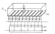
Fig. 3 is a schematic three dimensional view of not analyzing the focus/detector system of grating according to of the present invention;
Fig. 4 is the three-dimensional table diagrammatic sketch that is connected to the detector element of phase grating before;
Fig. 5 utilizes described analysis grating to detect the sketch map of phase shift;
Fig. 6 is not analyzing grating but the sketch maps that detect described phase shift under two groups of situations that have a structured detector element that detects band is being arranged;
Fig. 7 is the sketch map that utilizes the detector elements phase shift that has the detection band that is divided into four groups;
Fig. 8 is the three-dimensional table diagrammatic sketch that has the detector element of the detection band that is divided into two groups;
Fig. 9 shows the X ray CT system that has according to focus/detector system of the present invention with 3-D view.
The specific embodiment
Have grating group G for understanding described phase-contrast measurement better, in Fig. 1, schematically showing
0To G
2Focus/detector system.Focal point F
1Be positioned at the first grating G
0Before, its maximum extension is represented with w.The described first grating G
0Period p with grating line
0Height h with grizzly bar
0Accordingly, described grating G
1And G
2Also has height h
1And h
2And period p
1And p
2For playing the effect of phase measurement, must make described grating G
0And G
1Between spacing l and grating G
1And G
2Between spacing d meet specific relation mutually.Have at this:
The detector element E that has it
1To E
nDetector D
1To last grating G
2Distance unimportant.At this, the height h of the grizzly bar of described phase grating
1Should select like this, make corresponding to observed wavelength, just observed X-radiation energy and have following formula to set up at each grating material:
At this, n represents the refractive index of described grating material, and λ indicates to utilize it to measure the wavelength of the X ray of described phase shift.Advantageously, this grating can be adjusted on the energy, should in this energy range, provide enough number of photons at least corresponding to the characteristic curve of employed anodic X ray frequency spectrum.In current common tungsten anode, can use for example K
αLine.But, also there is the adjacent K in use location
βThe probability of line.Under the situation of having selected other anode material, must there be corresponding other energy that other configuration of phase grating also must be arranged thus.
The height h of described analysis grating
2Must be enough, so that be created in the grizzly bar that penetrates by X-radiation of described grating and the effective absorption difference between the idle as far as possible position, thereby form corresponding moire pattern at dorsal part.
Described grating G
0To G
2Line orientation be typically designed to, the described grating line of whole three gratings extends parallel to each other.In addition, advantageously, although and unnecessary be that described grating line is parallel to or is orientated perpendicular to system axle S ground, wherein, makes described grating G
0To G
2Major part is flatly constructed, and is orientated perpendicular to the centrage ground between focus and the detector centre.Yet, also might make the such ray path that cooperates described ray cone in surface of described grating in principle, make described grating vertically be cut apart by the ray between described focus and each detector element contact in each position, this causes forming the curvature of the correspondence of described grating.
In Fig. 2, illustrate once more from grating G
0And indivedual coherent radiations of patient P are crossed in the transmission that comes, and wherein, to after the penetrating of described patient the phase shift phenomenon are taking place.Thus, penetrating grating G
1The time, producing the conoscope image that shows by gray shade, it is by means of grating G
2At detector D subsequently
1And cause the different radiant intensity of each detector element on the detector element, thereby constitute so-called moire pattern at this place.Depend on analysis grating G if for example observe
2Skew x
GDetector element E
iAnd with intensity I (E
i(x
G)) be depicted as the skew x on the intensity I
GFunction, then obtain at described detector element E
iOn the sine-shaped rising and the decline of intensity I.If be each detector element E
iOr E
jAccording to described skew x
GDescribe this radiant intensity I that records, the different detector element that so just allow for the space X ray between the described focus of final formation and each detector element are similar to out function I (E
i(x
G)) or I (E
j(x
G)).According to described function, can be the definite phase shift each other of each detector element

Following formula is set up:
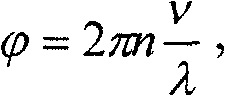
Wherein, v is corresponding to the voxel in the inspection object or the size of pixel, and n is its refractive index, and λ represents the wavelength of X-radiation.
Can be that the phase shift of determining every rays is measured at least three times of the analysis grating of every ray by utilizing skew respectively in the space by this way, thereby or under the situation of the X-ray photographs of projection, can directly calculate the pixel value of projection print, perhaps under the situation of CT examination, set up of the projection of its pixel value corresponding to described phase shift, make and to calculate by means of known reproducting method own thus, check which the space element in the object belongs to which part of measured phase shift.Thus, calculate tomographic image or stereo data in view of the above, described tomographic image or stereo data have reflected the local effect of the inspection object of relevant X-radiation phase shift once more.Because the minute differences in the composition has applied intensive effect to phase shift, so shown the very detailed of proximate relatively material, especially soft tissue itself and the intensive stereo data of contrast thus.
Such scheme for the detection that penetrates the described X ray phase shift of checking object, by means of on the analysis grating of repeatedly skew and the detector element after described analysis grating to the measurement of described X ray intensity, its shortcoming is, must be that every X ray is carried out at least three measurements under the situation of the analysis grating that is offset respectively.Thus, relatively slow to the scanning of checking object, and increased dose commitment simultaneously.Another problem is, owing to employed analysis grating has lost a part of radiation that is used to detect, because these radiation have been absorbed by described grating.
Therefore, the suggestion according to the present invention, save this analysis grating and replace such structure and detector element that described phase grating conjointly is provided with, make dose losses does not take place when measuring at least, preferably select a kind of like this distribution, make and to utilize unique one-shot measurement to determine the phase shift of observed ray.
A kind of such device in Fig. 3 shown in schematically illustrated in the three-dimensional table diagrammatic sketch of focus/detector system of CT (computer tomography).Focal point F shown in the figure
1, its ray path is provided with source grating G
0, and the phase grating G that produces the above-mentioned interference phenomenon is arranged in the detector side
1, described interference makes each one detector element can measure the radiating phase shift on the described detector element by subsequently detectors measure, speaking by the book is average phase-shift.Shown in the presentation graphs, the detector D that is configured to multi-row detector is shown in the detector side
1, wherein every row includes a plurality of detector element, and is connected to phase grating G before each detector element
1Optical grating construction.
Being combined among Fig. 4 between this grating and the detector element illustrates enlargedly.At this, structuredly show described detector element, wherein said detector element is by a plurality of detection band DS
1To DS
18Form, these detect band and be parallel to described phase grating G with regard to its orientations
1Grating line ground directed.It is to be noted that at this distribution that illustrates only is schematic distribution here, and different on the equipping rules in the practice with it.
In practice, a kind of size of such detector element is in the scope of 100 to 1000 μ m.Its order of magnitude must be in the period p in the extension of described detection band
2Be generally about 2 μ m, make described single detection band under its situation about being divided into two parts, be about one micron.
Fig. 5 has illustrated once more by means of analyzing grating G
2Basic principle of measurement is carried out in phase shift.This figure schematically illustrates x-ray photon stream Φ
PhOn the x axle after described phase grating the distance of Talbot distance (Talbotdistanz), wherein on the x axle, write down described photon stream Φ
Ph(x) variation.At this, the x axle extends perpendicular to described grating line.Then show and analyze grating G
2, this analysis grating has period p
2, and on its grizzly bar, absorb photon, only make that the clear position at described photon could penetrate downwards, and finally incide the detector element E that is positioned at thereafter
i, measure its intensity at this detector element place.If grating G
2At the x direction of principal axis small skew taking place, so just forms measured radiant intensity I on the detector element that is positioned at thereafter
PhStrong strength fluctuation, this can be by the skew x of described grating
GThe path describe.According to described radiant intensity and described analysis grating G
2Skew x
GBetween curve, can determine phase place for each detector element
 ,
,
According to the present invention, can substitute described analysis grating like this, make to detector element provides the structure that is similar to grating the intensity that wherein can record the intensity of passing described grating by comprehensive multi-ribbon (corresponding to the free space in described grating line or the described grating) respectively or be offset corresponding to half period of grating.Figure 6 illustrates a kind of such situation.At this, the top is at first again to illustrate on the x axle because the photon stream of the interference that phase grating causes.This photon stream incides on the detector element with different intensity, wherein, and with described detector element E
iBe divided into many and detect band DS
1To DS
6Described detection band alternately makes up with two different circuit A and B, makes to detect band DS
1, DS
3, DS
5... supply circuit B, and detect band DS
2, DS
4, DS
6... supply circuit A.By this way, can be respectively by analyzing the intensity change that grating (corresponding to Fig. 5) skew produced during the half period to measuring in the observation of measured dosage on circuit A or the circuit B.
If detecting the described same measurement of execution under the situation about being with half width slight shift detector or the slight shift that detects band, as other shown in broken lines, so just can carry out same measurement, thereby record corresponding intensity at this with described two circuit.If on X-axis, describe circuit A and B or have the measured intensity of the detector A ' and the B ' of slight shift, can as among the figure that illustrates below, carry out the coupling of sinusoidal line so, and determine the phase place of detected X-radiation thus

In the scheme of embodiment shown in Figure 6, also must carry out at least twice measurement, wherein when measuring, produce two measured values at every turn by described circuit A and B at this with the detection band of skew respectively; And as shown in Figure 7 according to the improvement embodiment of detection system of the present invention in can directly determine the phase place of the detected X-radiation of detector element with single measurement once.Fig. 7 illustrates and is similar to detector means shown in Figure 6, but designs in this wise for the division that detects detector element in the band, makes unique detection band only have four/one-period of pairing analysis grating.By this way, may connect described detection band like this, make per the 4th band be guided on the same circuit and the corresponding detection band group of formation.Carry out measurement on the ad-hoc location if utilize a kind of such detector means, just for the measurement of a specific X ray, so just can read respectively and the corresponding intensity of described phase place, and can measure directly definite phase place that arrives the X-radiation of described detector element according to these four times according to the intensity that on described circuit A, B, C, D, records.The analysis of this four measuring value A, B, C, D is shown in more below in the figure, also be noted that at this, these measure be not roughly with single detection band scope in the phase place of described X-radiation determine corresponding, but corresponding to the meansigma methods on the total surface of described detector element.At this especially advantageously, in measurement, introduced the total used dosage that shines described inspection object, especially patient,, and do not produced any dose losses thus so that make analysis.
That is to say that core of the present invention is, a detector element is divided into many detects band, described detection band is read out in groups at measured X ray intensity, wherein, described division must be carried out like this, makes it on the one hand in the period p of the analysis grating of correspondence
2In coupling, yet simultaneously each cycle have at least two, be preferably at least three and detect band, make each cycle once represent described detection with on each group.Promptly, may in one-period, settle two, three, four, five or more detection bands by this dividing mode, and on the direction perpendicular to described detection band orientation, should divide multichannel and form a line abreast, make the number of described measurement group corresponding to phase p weekly
2The number of detection band.
A kind of so exemplary embodiment of detector element is shown in Figure 8 once more, and wherein, described detection band becomes two groups Di to be connected with B with passage A at this.
A kind of complete computer CT system that is used to carry out the method according to this invention is shown in Figure 9.The figure shows CT system 1, it has first focus/detector system that has X-ray tube 2 detector relative with the position 3, and described X-ray tube and detector are arranged on the frame that is not shown specifically in the holster shell 6.In the ray path of described first focus/detector system 2,3, be provided with optical-mechanical system as shown in Figures 1 to 3, make the patient 7 be arranged on patient's bed 8 that can move along system's axle 9 to move in the ray path of described first focus/detector system and to be scanned at this place.The control of described CT system is by calculating and control unit 10 is carried out, and Prg has program stored therein in memorizer 11 in this calculating and control unit
1To Prg
n, described program is carried out above-mentioned the method according to this invention, and reproduces corresponding computed tomography images according to the measured phase shift of depending on ray.
Optional is that second focus/detector system rather than unique focus/detector system can be set in described holster shell.This represents by X-ray tube shown in broken lines among Fig. 94 and detector 5 shown in broken lines.
As a supplement be also will point out, utilize shown focus/detector system not only can measure the phase shift of described X-radiation, and this focus/detector system also is applicable to traditional measurement that radiation is absorbed and for the reproduction of the absorption photo of correspondence.Also can produce the absorption and the phase-contrast photo of combination in case of necessity.
It should be appreciated that in the embodiment of reality, the space that can fill between the described grating line with the material of high-absorbility contrasts to improve under the situation of the source of use grating.For example, can use gold for this reason.Basically, should design described source grating like this, make it reach the coefficient of correlation that is at least e-1.
Should be appreciated that above-mentioned feature of the present invention not only can use according to the various combinations that provide, and can be according to other combination or use individually, and do not exceed scope of the present invention.
Claims (17)
1. focus/detector system (2,3) that is used to produce the X-ray equipment of phase-contrast photo projection or tomography, it is made up of following part at least:
1.1 radiation source, this radiation source has focus (F
1) and the source grating (G of focus side
0), this source grating is arranged in the ray path, and produces the relevant X ray (S of a ray
i) the field,
1.2 grating/detector means, this grating/detector means has phase grating (G
1) and detector (D
1), this phase grating has and is parallel to source grating (G
0) grating line that is provided with, to produce conoscope image; This detector has the detector element (E that a plurality of planes are provided with
i), to measure at described phase grating (G
1) afterwards radiant intensity,
1.3 wherein, described detector element (E
i) by the detection band (DS of a plurality of elongations
x) constitute, these detect band and are parallel to described phase grating (G
1) described grating line ground orientation.
2. require 1 described focus/detector system according to aforesaid right, it is characterized in that, described grating/detector means is configured and disposed like this, makes it satisfy following geometrical condition:
p
2=k×p
DS,
Wherein have,
p
0=described source grating G
0The grating cycle,
p
1=described phase grating G
1The grating cycle,
p
2=detect and be with D
sLarge period, the spacing of the interference line after described analysis grating,
p
DS=detect and be with D
sMinor cycle, the spacing between the centrage of adjacent detection band,
D=in the fan ray geometry, described phase grating G
1To described analysis grating G
2Or to described detection band DS
XSpacing,
d
≡=under parallel geometry, described phase grating G
1To described analysis grating G
2Or to described detection band DS
XSpacing,
k =2,3,4,5,...,
The described source of l=grating G
0To described phase grating G
1Distance,
λ=selected radiation wavelength,
h
1=described phase grating G
1Grizzly bar height on directions of rays,
The refractive index of the grating material of the described phase grating of n=.
3. require any one described focus/detector system in 1 to 2 according to aforesaid right, it is characterized in that described detection band (DS
X) constitute as the detection band of directly conversion.
4. require 1 or 2 described focus/detector systems according to aforesaid right, it is characterized in that at least one detector element (E
i) the n bar detect band (DS
X) with being connected of m circuit read electronic equipment and read radiant intensity so that alternately and in groups utilize according to m step, wherein, 2≤m<<n.
5. require 4 described focus/detector systems according to aforesaid right, it is characterized in that, be provided with lucky two circuit (A, B).
6. require 4 described focus/detector systems according to aforesaid right, it is characterized in that, be provided with lucky three circuit (A, B, C) or four circuit (A, B, C, D).
7. x-ray system that is used to produce the phase-contrast photo of projection, it has at least one according to any one described focus/detector system (2,3) in the aforesaid right requirement 1 to 6.
8. x-ray system according to claim 7 is characterized in that, is provided with computing unit (10), and this computing unit is used to control the skew of described detection band and according to the detection band of differently skew the repeatedly ionization meter of same ray being calculated phase shift.
9. X ray C shape shelf system that is used to produce phase-contrast photo projection or tomography, it has according to any one described focus/detector system in the aforesaid right requirement 1 to 6, and this system is arranged at can be around checking on the C shape shelf that object rotates.
10. X ray C shape shelf according to claim 9 system, it is characterized in that, be provided with computing unit (10), this computing unit is used to control the skew of described detection band and according to the detection band of differently skew the repeatedly ionization meter of same ray being calculated phase shift.
11. X ray CT system (1) that is used to produce the phase-contrast photo of tomography, it has at least one according to any one described focus/detector system (2 in the aforesaid right requirement 1 to 6,3), be arranged at can be around checking on the frame that object rotates in this system.
12. X ray CT system according to claim 11 (1), it is characterized in that, be provided with computing unit (10), this computing unit is used to control the skew of described detection band and according to the detection band of differently skew the repeatedly ionization meter of same ray being calculated phase shift.
13. a utilization produces the method for the X-ray photographs of the projection of checking object according to any one described focus/detector system (2,3) in the claim 1 to 6, wherein carries out following method step at least:
13.1, wherein, in the space, pass through the connecting line and the detector element (E of focus-detector element by the described inspection object of beam transmission (7)
i) extension with respect to direction with extend and to define every ray, 13.2 by being the detection band (DS of every ray by means of fine structureization
X) measure described radiation in continuous and the skew setting or the detection band (DS of offset orientation mutually mutually in groups
X) on intensity (I (E
i(x
G))), measure the average phase-shift of these rays

13.3 average phase-shift according to the described ray that records
 Set up the phase-contrast photo, the pixel value of described phase-contrast photo is represented the average phase-shift of every ray
14. require 13 described methods, it is characterized in that detector element (E according to aforesaid right
i) described detection band (DS
X) alternately (A B) is connected, and passes through detector element (E under the situation of the detector offset that does not have blanking time with two measuring circuits
i) described two measuring circuits (A B) detects band (DS at described two groups
X) go up and carry out at least twice ionization meter, then, carry out once described detection band (DS at least
X) spatial deviation of group, and carry out other twice measurement to the same space ray.
15. require 13 described methods according to aforesaid right, it is characterized in that, detect band (DS
X) group spatial deviation (x
G) realize with circuit engineering.
16. require 13 described methods according to aforesaid right, it is characterized in that, detect band (DS
X) group spatial deviation (x
G) physically realize.
17. require 13 described methods, it is characterized in that described detector element (E according to aforesaid right
i) detection band (DS
X) and at least three measuring circuit (A, B C) alternately is connected, and passes through described three measuring circuit (A of detector element under the situation of the detector offset that does not have blanking time, B, C) being with three groups of detections is that a ray is carried out ionization meter at least three times.
Applications Claiming Priority (4)
| Application Number | Priority Date | Filing Date | Title |
|---|---|---|---|
| DE102006004976.4 | 2006-02-01 | ||
| DE102006004976 | 2006-02-01 | ||
| DE102006017290.6 | 2006-04-12 | ||
| DE102006017290.6A DE102006017290B4 (en) | 2006-02-01 | 2006-04-12 | Focus / detector system of an X-ray apparatus, X-ray system and method for producing phase-contrast images |
Publications (2)
| Publication Number | Publication Date |
|---|---|
| CN101011252A CN101011252A (en) | 2007-08-08 |
| CN101011252B true CN101011252B (en) | 2010-12-22 |
Family
ID=38164636
Family Applications (4)
| Application Number | Title | Priority Date | Filing Date |
|---|---|---|---|
| CN2007101035154A Active CN101036582B (en) | 2006-02-01 | 2007-02-01 | Method for creating phase contrast image by projection or tomography imaging |
| CN2007100079583A Expired - Fee Related CN101011254B (en) | 2006-02-01 | 2007-02-01 | Focal point and detector system of an X-ray apparatus for producing phase-contrast images |
| CN2007100079507A Active CN101011251B (en) | 2006-02-01 | 2007-02-01 | Focus/detector system of an X-ray apparatus for generating phase contrast recordings |
| CN2007100079530A Expired - Fee Related CN101011252B (en) | 2006-02-01 | 2007-02-01 | Focus/detector system of an X-ray apparatus for generating phase contrast recordings |
Family Applications Before (3)
| Application Number | Title | Priority Date | Filing Date |
|---|---|---|---|
| CN2007101035154A Active CN101036582B (en) | 2006-02-01 | 2007-02-01 | Method for creating phase contrast image by projection or tomography imaging |
| CN2007100079583A Expired - Fee Related CN101011254B (en) | 2006-02-01 | 2007-02-01 | Focal point and detector system of an X-ray apparatus for producing phase-contrast images |
| CN2007100079507A Active CN101011251B (en) | 2006-02-01 | 2007-02-01 | Focus/detector system of an X-ray apparatus for generating phase contrast recordings |
Country Status (5)
| Country | Link |
|---|---|
| US (1) | US7945018B2 (en) |
| JP (1) | JP2009525084A (en) |
| CN (4) | CN101036582B (en) |
| DE (2) | DE102006063048B3 (en) |
| WO (1) | WO2007087789A1 (en) |
Cited By (1)
| Publication number | Priority date | Publication date | Assignee | Title |
|---|---|---|---|---|
| US8972191B2 (en) | 2009-02-05 | 2015-03-03 | Paul Scherrer Institut | Low dose single step grating based X-ray phase contrast imaging |
Families Citing this family (107)
| Publication number | Priority date | Publication date | Assignee | Title |
|---|---|---|---|---|
| DE102007022519A1 (en) * | 2007-05-14 | 2008-11-20 | Siemens Ag | Method for determining individual quantum absorption events in a radiation converter for converting individual quanta of an incident ionizing radiation thereon. Program code means for carrying out the method, device for electronic data processing, radiation converter and imaging tomography device |
| CN101576515B (en) * | 2007-11-23 | 2012-07-04 | 同方威视技术股份有限公司 | System and method for X-ray optical grating contrast imaging |
| JP5438022B2 (en) * | 2007-11-26 | 2014-03-12 | コーニンクレッカ フィリップス エヌ ヴェ | X-ray phase contrast imaging detection setup |
| CN101467889B (en) * | 2007-12-26 | 2010-08-25 | 中国科学院高能物理研究所 | Grating shearing phase contrast CT image-forming data acquisition and reconstruction method |
| JP5339975B2 (en) * | 2008-03-13 | 2013-11-13 | キヤノン株式会社 | Phase grating used for X-ray phase imaging, X-ray phase contrast image imaging apparatus using the phase grating, X-ray computed tomography system |
| US8565371B2 (en) | 2008-03-19 | 2013-10-22 | Koninklijke Philips N.V. | Rotational X ray device for phase contrast imaging |
| CN101726503B (en) * | 2008-10-17 | 2012-08-29 | 清华大学 | X ray phase contrast tomography |
| JP4847568B2 (en) * | 2008-10-24 | 2011-12-28 | キヤノン株式会社 | X-ray imaging apparatus and X-ray imaging method |
| WO2010050483A1 (en) * | 2008-10-29 | 2010-05-06 | キヤノン株式会社 | X-ray imaging device and x-ray imaging method |
| DE102009004702B4 (en) * | 2009-01-15 | 2019-01-31 | Paul Scherer Institut | Arrangement and method for projective and / or tomographic phase-contrast imaging with X-radiation |
| US7949095B2 (en) * | 2009-03-02 | 2011-05-24 | University Of Rochester | Methods and apparatus for differential phase-contrast fan beam CT, cone-beam CT and hybrid cone-beam CT |
| JP5631967B2 (en) | 2009-03-27 | 2014-11-26 | コーニンクレッカ フィリップス エヌ ヴェ | Achromatic phase contrast imaging |
| WO2010109368A1 (en) * | 2009-03-27 | 2010-09-30 | Koninklijke Philips Electronics N.V. | Differential phase-contrast imaging with circular gratings |
| DE102009035286A1 (en) * | 2009-07-30 | 2011-02-10 | Siemens Aktiengesellschaft | Method and device for displaying computed tomographic examination data of an examination object |
| JP2013513418A (en) * | 2009-12-10 | 2013-04-22 | コーニンクレッカ フィリップス エレクトロニクス エヌ ヴィ | Differential phase contrast imaging system |
| JP5213923B2 (en) | 2010-01-29 | 2013-06-19 | キヤノン株式会社 | X-ray imaging apparatus and X-ray imaging method |
| CN102221565B (en) * | 2010-04-19 | 2013-06-12 | 清华大学 | X-ray source grating stepping imaging system and imaging method |
| CN102906783B (en) * | 2010-05-21 | 2015-12-02 | 皇家飞利浦电子股份有限公司 | For the treatment of the image processing apparatus of image |
| JP5646906B2 (en) * | 2010-08-06 | 2014-12-24 | キヤノン株式会社 | X-ray apparatus and X-ray measuring method |
| US9105369B2 (en) * | 2010-09-03 | 2015-08-11 | Koninklijke Philips N.V. | Differential phase-contrast imaging with improved sampling |
| WO2012052900A1 (en) * | 2010-10-19 | 2012-04-26 | Koninklijke Philips Electronics N.V. | Differential phase-contrast imaging |
| US10028716B2 (en) * | 2010-10-19 | 2018-07-24 | Koniklijke Philips N.V. | Differential phase-contrast imaging |
| EP2865336A1 (en) * | 2010-10-27 | 2015-04-29 | Fujifilm Corporation | Radiography system and radiograph generation method |
| WO2012056724A1 (en) | 2010-10-29 | 2012-05-03 | 富士フイルム株式会社 | Phase contrast radiation imaging device |
| JP2012095865A (en) * | 2010-11-02 | 2012-05-24 | Fujifilm Corp | Radiographic apparatus and radiographic system |
| US20130223595A1 (en) * | 2010-11-08 | 2013-08-29 | Koninklijke Philips Electronics N.V. | Grating for phase contrast imaging |
| JP5150711B2 (en) * | 2010-12-07 | 2013-02-27 | 富士フイルム株式会社 | Radiography apparatus and radiation imaging system |
| DE102011076346B4 (en) | 2011-05-24 | 2016-07-14 | Siemens Healthcare Gmbh | Method and computer tomography system for generating tomographic image data sets |
| EP2713884B1 (en) | 2011-06-01 | 2019-07-31 | Total SA | An x-ray tomography device |
| BR112013030647A2 (en) * | 2011-06-01 | 2016-11-29 | Total Sa | x-ray tomography device |
| WO2013027138A1 (en) | 2011-08-19 | 2013-02-28 | Koninklijke Philips Electronics N.V. | Frequency dependent combination of x-ray images of different modalities |
| DE102011082878A1 (en) * | 2011-09-16 | 2013-03-21 | Siemens Aktiengesellschaft | X-ray detector of a grid-based phase-contrast X-ray device and method for operating a grid-based phase-contrast X-ray device |
| US20150117599A1 (en) | 2013-10-31 | 2015-04-30 | Sigray, Inc. | X-ray interferometric imaging system |
| US9538970B2 (en) * | 2012-01-12 | 2017-01-10 | Koninklijke Philips N.V. | Generating attenuation image data and phase image data in an X-ray system |
| RU2624513C2 (en) * | 2012-01-24 | 2017-07-04 | Конинклейке Филипс Н.В. | Multidirectional phase-contrast x-ray visualization |
| WO2014137318A1 (en) * | 2012-03-05 | 2014-09-12 | University Of Rochester | Methods and apparatus for differential phase-contrast cone-beam ct and hybrid cone-beam ct |
| DE102012005767A1 (en) * | 2012-03-25 | 2013-09-26 | DüRR DENTAL AG | Phase contrast X-ray tomography apparatus |
| JP2013208189A (en) * | 2012-03-30 | 2013-10-10 | Canon Inc | X-ray imaging apparatus and x-ray imaging method |
| WO2013187150A1 (en) | 2012-06-11 | 2013-12-19 | コニカミノルタ株式会社 | Medical image system and medical image processing device |
| KR101378757B1 (en) * | 2012-08-30 | 2014-03-27 | 한국원자력연구원 | Radiation imaging equipment and method available to obtain element date of material and select dimensions of image |
| TWI625071B (en) | 2012-09-26 | 2018-05-21 | Nikon Corporation | X-ray device and manufacturing method of structure |
| JP6116222B2 (en) | 2012-12-13 | 2017-04-19 | キヤノン株式会社 | Arithmetic device, program, and imaging system |
| US8989347B2 (en) | 2012-12-19 | 2015-03-24 | General Electric Company | Image reconstruction method for differential phase contrast X-ray imaging |
| US9724063B2 (en) | 2012-12-21 | 2017-08-08 | Carestream Health, Inc. | Surrogate phantom for differential phase contrast imaging |
| US9700267B2 (en) | 2012-12-21 | 2017-07-11 | Carestream Health, Inc. | Method and apparatus for fabrication and tuning of grating-based differential phase contrast imaging system |
| CN104869905B (en) * | 2012-12-21 | 2019-08-06 | 卡尔斯特里姆保健公司 | Medical radiation photograph grating based on differential contrast imaging |
| US10096098B2 (en) | 2013-12-30 | 2018-10-09 | Carestream Health, Inc. | Phase retrieval from differential phase contrast imaging |
| US9494534B2 (en) * | 2012-12-21 | 2016-11-15 | Carestream Health, Inc. | Material differentiation with phase contrast imaging |
| US9907524B2 (en) | 2012-12-21 | 2018-03-06 | Carestream Health, Inc. | Material decomposition technique using x-ray phase contrast imaging system |
| US9357975B2 (en) | 2013-12-30 | 2016-06-07 | Carestream Health, Inc. | Large FOV phase contrast imaging based on detuned configuration including acquisition and reconstruction techniques |
| US10578563B2 (en) | 2012-12-21 | 2020-03-03 | Carestream Health, Inc. | Phase contrast imaging computed tomography scanner |
| JP2014140632A (en) | 2012-12-27 | 2014-08-07 | Canon Inc | Computation apparatus, image acquisition method, program, and x-ray imaging system |
| DE102013205406A1 (en) * | 2013-03-27 | 2014-10-16 | Siemens Aktiengesellschaft | X-ray imaging system for X-ray imaging at high image frequencies of an examination subject by direct measurement of the interference pattern |
| EP2827339A1 (en) * | 2013-07-16 | 2015-01-21 | Canon Kabushiki Kaisha | Source grating, interferometer, and object information acquisition system |
| US10297359B2 (en) | 2013-09-19 | 2019-05-21 | Sigray, Inc. | X-ray illumination system with multiple target microstructures |
| US10295485B2 (en) | 2013-12-05 | 2019-05-21 | Sigray, Inc. | X-ray transmission spectrometer system |
| US10269528B2 (en) | 2013-09-19 | 2019-04-23 | Sigray, Inc. | Diverging X-ray sources using linear accumulation |
| US10304580B2 (en) | 2013-10-31 | 2019-05-28 | Sigray, Inc. | Talbot X-ray microscope |
| USRE48612E1 (en) | 2013-10-31 | 2021-06-29 | Sigray, Inc. | X-ray interferometric imaging system |
| JP2015166676A (en) * | 2014-03-03 | 2015-09-24 | キヤノン株式会社 | X-ray imaging system |
| US10401309B2 (en) | 2014-05-15 | 2019-09-03 | Sigray, Inc. | X-ray techniques using structured illumination |
| CN106999125B (en) | 2014-11-11 | 2021-02-02 | 皇家飞利浦有限公司 | Source-detector arrangement |
| JP6451400B2 (en) * | 2015-02-26 | 2019-01-16 | コニカミノルタ株式会社 | Image processing system and image processing apparatus |
| WO2016170685A1 (en) | 2015-04-24 | 2016-10-27 | 株式会社ニコン | X-ray inspection device, x-ray inspection method, and method for manufacturing structure |
| US10352880B2 (en) | 2015-04-29 | 2019-07-16 | Sigray, Inc. | Method and apparatus for x-ray microscopy |
| CN107743379B (en) * | 2015-06-15 | 2021-10-22 | 皇家飞利浦有限公司 | Tiled detector arrangement for differential phase contrast CT |
| WO2016207423A1 (en) * | 2015-06-26 | 2016-12-29 | Koninklijke Philips N.V. | Robust reconstruction for dark-field and phase contrast ct |
| US10295486B2 (en) | 2015-08-18 | 2019-05-21 | Sigray, Inc. | Detector for X-rays with high spatial and high spectral resolution |
| EP3452982B1 (en) * | 2016-05-04 | 2019-10-02 | Koninklijke Philips N.V. | Feature suppression in dark field or phase contrast x-ray imaging |
| DE102016217509A1 (en) | 2016-09-14 | 2018-03-15 | Siemens Healthcare Gmbh | Method and X-ray device for generating a projective X-ray representation of an examination object |
| CN109964118A (en) * | 2016-11-10 | 2019-07-02 | 皇家飞利浦有限公司 | Grating-Based Phase Contrast Imaging |
| US10247683B2 (en) | 2016-12-03 | 2019-04-02 | Sigray, Inc. | Material measurement techniques using multiple X-ray micro-beams |
| WO2018104132A1 (en) * | 2016-12-06 | 2018-06-14 | Koninklijke Philips N.V. | Interferometer grating support for grating-based x-ray imaging and/or a support bracket therefor |
| JP6753342B2 (en) * | 2017-03-15 | 2020-09-09 | 株式会社島津製作所 | Radiation grid detector and X-ray inspection equipment |
| WO2018175570A1 (en) | 2017-03-22 | 2018-09-27 | Sigray, Inc. | Method of performing x-ray spectroscopy and x-ray absorption spectrometer system |
| JP6798408B2 (en) * | 2017-04-21 | 2020-12-09 | 株式会社島津製作所 | X-ray phase imaging device |
| EP3446630A1 (en) * | 2017-08-23 | 2019-02-27 | Koninklijke Philips N.V. | Device and method for phase stepping in phase contrast image acquisition |
| CN108460753A (en) * | 2018-01-03 | 2018-08-28 | 沈阳东软医疗系统有限公司 | Dual energy CT image processing method, device and equipment |
| JP7020169B2 (en) * | 2018-02-23 | 2022-02-16 | コニカミノルタ株式会社 | X-ray system |
| US10578566B2 (en) | 2018-04-03 | 2020-03-03 | Sigray, Inc. | X-ray emission spectrometer system |
| US10989822B2 (en) | 2018-06-04 | 2021-04-27 | Sigray, Inc. | Wavelength dispersive x-ray spectrometer |
| US10658145B2 (en) | 2018-07-26 | 2020-05-19 | Sigray, Inc. | High brightness x-ray reflection source |
| US10656105B2 (en) | 2018-08-06 | 2020-05-19 | Sigray, Inc. | Talbot-lau x-ray source and interferometric system |
| JP7144805B2 (en) * | 2018-08-21 | 2022-09-30 | キヤノン株式会社 | Image processing device, image processing method, program |
| US10962491B2 (en) | 2018-09-04 | 2021-03-30 | Sigray, Inc. | System and method for x-ray fluorescence with filtering |
| DE112019004478T5 (en) | 2018-09-07 | 2021-07-08 | Sigray, Inc. | SYSTEM AND PROCEDURE FOR X-RAY ANALYSIS WITH SELECTABLE DEPTH |
| CN113271860A (en) * | 2018-10-23 | 2021-08-17 | 兰斯芙丽有限公司 | System and method for X-ray imaging |
| CN114729907B (en) | 2019-09-03 | 2023-05-23 | 斯格瑞公司 | Systems and methods for computed tomography fluorescence imaging |
| US11175243B1 (en) | 2020-02-06 | 2021-11-16 | Sigray, Inc. | X-ray dark-field in-line inspection for semiconductor samples |
| JP7395775B2 (en) | 2020-05-18 | 2023-12-11 | シグレイ、インコーポレイテッド | Systems and methods for X-ray absorption spectroscopy using a crystal analyzer and multiple detector elements |
| DE102020209703A1 (en) * | 2020-07-31 | 2022-02-03 | Siemens Healthcare Gmbh | Providing a 3D image data set of an examination object |
| CN112184794B (en) * | 2020-09-16 | 2023-02-10 | 西安邮电大学 | Phase shifting method for extracting main value phase of grating stripe |
| WO2022061347A1 (en) | 2020-09-17 | 2022-03-24 | Sigray, Inc. | System and method using x-rays for depth-resolving metrology and analysis |
| DE112021006348T5 (en) | 2020-12-07 | 2023-09-21 | Sigray, Inc. | HIGH-THROUGHPUT 3D X-RAY IMAGING SYSTEM USING A TRANSMISSION X-RAY SOURCE |
| US12480892B2 (en) | 2020-12-07 | 2025-11-25 | Sigray, Inc. | High throughput 3D x-ray imaging system using a transmission x-ray source |
| CN113096724B (en) * | 2021-04-09 | 2022-08-02 | 中国科学院近代物理研究所 | Four-dimensional dose calculation system and storage medium |
| WO2023168204A1 (en) | 2022-03-02 | 2023-09-07 | Sigray, Inc. | X-ray fluorescence system and x-ray source with electrically insulative target material |
| DE112023001408T5 (en) | 2022-03-15 | 2025-02-13 | Sigray, Inc. | SYSTEM AND METHOD FOR COMPACT LAMINOGRAPHY USING A MICROFOCUS TRANSMISSION X-RAY SOURCE AND A VARIABLE MAGNIFICATION X-RAY DETECTOR |
| JP2025515085A (en) | 2022-05-02 | 2025-05-13 | シグレイ、インコーポレイテッド | X-ray sequential array wavelength dispersive spectrometer |
| WO2024173256A1 (en) | 2023-02-16 | 2024-08-22 | Sigray, Inc. | X-ray detector system with at least two stacked flat bragg diffractors |
| CN116849690B (en) * | 2023-08-09 | 2024-11-19 | 佛山瑞迪奥医疗系统有限公司 | SPECT imaging device, SPECT imaging system and diagnosis combination |
| US12181423B1 (en) | 2023-09-07 | 2024-12-31 | Sigray, Inc. | Secondary image removal using high resolution x-ray transmission sources |
| US12429437B2 (en) | 2023-11-07 | 2025-09-30 | Sigray, Inc. | System and method for x-ray absorption spectroscopy using spectral information from two orthogonal planes |
| CN120189138A (en) * | 2023-12-21 | 2025-06-24 | 同方威视技术股份有限公司 | Static CT equipment and CT examination methods |
| WO2025151383A1 (en) | 2024-01-08 | 2025-07-17 | Sigray, Inc. | X-ray analysis system with focused x-ray beam and non-x-ray microscope |
| WO2025155719A1 (en) | 2024-01-18 | 2025-07-24 | Sigray, Inc. | Sequential array of x-ray imaging detectors |
| US12431256B2 (en) | 2024-02-15 | 2025-09-30 | Sigray, Inc. | System and method for generating a focused x-ray beam |
Citations (3)
| Publication number | Priority date | Publication date | Assignee | Title |
|---|---|---|---|---|
| US4057745A (en) * | 1974-06-24 | 1977-11-08 | Albert Richard D | Scanning X-ray source |
| US5745546A (en) * | 1995-03-20 | 1998-04-28 | Siemens Aktiengesellschaft | Anode for an x-ray tube |
| US5812629A (en) * | 1997-04-30 | 1998-09-22 | Clauser; John F. | Ultrahigh resolution interferometric x-ray imaging |
Family Cites Families (12)
| Publication number | Priority date | Publication date | Assignee | Title |
|---|---|---|---|---|
| AUPN201295A0 (en) * | 1995-03-28 | 1995-04-27 | Commonwealth Scientific And Industrial Research Organisation | Simplified conditions and configurations for phase-contrast imaging with hard x-rays |
| JP4118535B2 (en) * | 2001-07-03 | 2008-07-16 | 株式会社日立メディコ | X-ray inspection equipment |
| JP4352644B2 (en) * | 2001-09-26 | 2009-10-28 | コニカミノルタホールディングス株式会社 | X-ray imaging system |
| JP2003325501A (en) * | 2002-05-16 | 2003-11-18 | Fuji Photo Film Co Ltd | Apparatus, method and program for radiation image pickup |
| JP2004089445A (en) * | 2002-08-30 | 2004-03-25 | Konica Minolta Holdings Inc | X ray generating apparatus and x-ray image photographing system |
| WO2004058070A1 (en) * | 2002-12-26 | 2004-07-15 | Atsushi Momose | X-ray imaging system and imaging method |
| EP1447046A1 (en) | 2003-02-14 | 2004-08-18 | Paul Scherrer Institut | Apparatus and method to obtain phase contrast x-ray images |
| DE102004004630B4 (en) * | 2004-01-29 | 2009-12-31 | Siemens Ag | X-ray equipment |
| EP1731099A1 (en) | 2005-06-06 | 2006-12-13 | Paul Scherrer Institut | Interferometer for quantitative phase contrast imaging and tomography with an incoherent polychromatic x-ray source |
| DE102006015358B4 (en) * | 2006-02-01 | 2019-08-22 | Paul Scherer Institut | Focus / detector system of an X-ray apparatus for producing phase-contrast images, associated X-ray system and storage medium and method for producing tomographic images |
| DE102006037256B4 (en) * | 2006-02-01 | 2017-03-30 | Paul Scherer Institut | Focus-detector arrangement of an X-ray apparatus for producing projective or tomographic phase contrast recordings and X-ray system, X-ray C-arm system and X-ray CT system |
| DE102006037282B4 (en) * | 2006-02-01 | 2017-08-17 | Siemens Healthcare Gmbh | Focus-detector arrangement with X-ray optical grating for phase contrast measurement |
-
2006
- 2006-04-12 DE DE102006063048.3A patent/DE102006063048B3/en not_active Expired - Fee Related
-
2007
- 2007-01-30 JP JP2008552673A patent/JP2009525084A/en active Pending
- 2007-01-30 WO PCT/DE2007/000160 patent/WO2007087789A1/en not_active Ceased
- 2007-01-30 DE DE112007000806T patent/DE112007000806A5/en not_active Withdrawn
- 2007-01-30 US US12/223,061 patent/US7945018B2/en active Active
- 2007-02-01 CN CN2007101035154A patent/CN101036582B/en active Active
- 2007-02-01 CN CN2007100079583A patent/CN101011254B/en not_active Expired - Fee Related
- 2007-02-01 CN CN2007100079507A patent/CN101011251B/en active Active
- 2007-02-01 CN CN2007100079530A patent/CN101011252B/en not_active Expired - Fee Related
Patent Citations (3)
| Publication number | Priority date | Publication date | Assignee | Title |
|---|---|---|---|---|
| US4057745A (en) * | 1974-06-24 | 1977-11-08 | Albert Richard D | Scanning X-ray source |
| US5745546A (en) * | 1995-03-20 | 1998-04-28 | Siemens Aktiengesellschaft | Anode for an x-ray tube |
| US5812629A (en) * | 1997-04-30 | 1998-09-22 | Clauser; John F. | Ultrahigh resolution interferometric x-ray imaging |
Cited By (1)
| Publication number | Priority date | Publication date | Assignee | Title |
|---|---|---|---|---|
| US8972191B2 (en) | 2009-02-05 | 2015-03-03 | Paul Scherrer Institut | Low dose single step grating based X-ray phase contrast imaging |
Also Published As
| Publication number | Publication date |
|---|---|
| JP2009525084A (en) | 2009-07-09 |
| CN101011251B (en) | 2012-11-14 |
| CN101011252A (en) | 2007-08-08 |
| CN101011254B (en) | 2011-10-05 |
| CN101011251A (en) | 2007-08-08 |
| WO2007087789A1 (en) | 2007-08-09 |
| DE112007000806A5 (en) | 2009-01-02 |
| CN101036582B (en) | 2012-12-05 |
| CN101011254A (en) | 2007-08-08 |
| DE102006063048B3 (en) | 2018-03-29 |
| US7945018B2 (en) | 2011-05-17 |
| US20100220834A1 (en) | 2010-09-02 |
| CN101036582A (en) | 2007-09-19 |
Similar Documents
| Publication | Publication Date | Title |
|---|---|---|
| CN101011252B (en) | Focus/detector system of an X-ray apparatus for generating phase contrast recordings | |
| JP5142540B2 (en) | X-ray device focus-detector system | |
| US7646843B2 (en) | Method for producing projective and tomographic phase contrast images with the aid of an X-ray system | |
| US7492871B2 (en) | Focus/detector system of an x-ray apparatus for generating phase contrast recordings | |
| CN101013613B (en) | X-ray optical transmission grating of a focus-detector arrangement of an X-ray apparatus | |
| JP5961614B2 (en) | Grating apparatus for phase contrast imaging, apparatus for phase contrast imaging, X-ray system having the apparatus, and method of using the apparatus | |
| US7535986B2 (en) | Method and CT system for detecting and differentiating plaque in vessel structures of a patient | |
| US9084528B2 (en) | Phase contrast imaging | |
| EP2586373B1 (en) | X-ray interferometer | |
| CN101952900A (en) | X-ray detector for phase contrast imaging | |
| US9575015B2 (en) | Systems and methods for x-ray phase contrast imaging using arrays of x-ray focusing elements | |
| Fu et al. | Helical differential X-ray phase-contrast computed tomography | |
| CN104427938A (en) | Method and x-ray system for generating a phase contrast image | |
| EP3102109B1 (en) | Computed tomography (ct) hybrid data acquisition | |
| Chen et al. | Image reconstruction for fan-beam differential phase contrast computed tomography | |
| Wang | Recent advances in X-ray grating-based dark-field imaging | |
| US12248108B2 (en) | High-resolution detector having a reduced number of pixels | |
| US20210173103A1 (en) | Computerized tomography system | |
| Krejci et al. | Low dose X-ray phase contrast imaging sensitive to phase effects in 2-D |
Legal Events
| Date | Code | Title | Description |
|---|---|---|---|
| C06 | Publication | ||
| PB01 | Publication | ||
| C10 | Entry into substantive examination | ||
| SE01 | Entry into force of request for substantive examination | ||
| C14 | Grant of patent or utility model | ||
| GR01 | Patent grant | ||
| CF01 | Termination of patent right due to non-payment of annual fee |
Granted publication date: 20101222 Termination date: 20190201 |
|
| CF01 | Termination of patent right due to non-payment of annual fee |