CN101001752B - Inkjet recording head and inkjet recording device - Google Patents
Inkjet recording head and inkjet recording device Download PDFInfo
- Publication number
- CN101001752B CN101001752B CN2005800248097A CN200580024809A CN101001752B CN 101001752 B CN101001752 B CN 101001752B CN 2005800248097 A CN2005800248097 A CN 2005800248097A CN 200580024809 A CN200580024809 A CN 200580024809A CN 101001752 B CN101001752 B CN 101001752B
- Authority
- CN
- China
- Prior art keywords
- recording head
- liquid discharge
- liquid
- support
- discharge substrate
- Prior art date
- Legal status (The legal status is an assumption and is not a legal conclusion. Google has not performed a legal analysis and makes no representation as to the accuracy of the status listed.)
- Expired - Fee Related
Links
Images


Classifications
-
- B—PERFORMING OPERATIONS; TRANSPORTING
- B41—PRINTING; LINING MACHINES; TYPEWRITERS; STAMPS
- B41J—TYPEWRITERS; SELECTIVE PRINTING MECHANISMS, i.e. MECHANISMS PRINTING OTHERWISE THAN FROM A FORME; CORRECTION OF TYPOGRAPHICAL ERRORS
- B41J2/00—Typewriters or selective printing mechanisms characterised by the printing or marking process for which they are designed
- B41J2/005—Typewriters or selective printing mechanisms characterised by the printing or marking process for which they are designed characterised by bringing liquid or particles selectively into contact with a printing material
- B41J2/01—Ink jet
- B41J2/135—Nozzles
- B41J2/14—Structure thereof only for on-demand ink jet heads
- B41J2/14016—Structure of bubble jet print heads
- B41J2/14072—Electrical connections, e.g. details on electrodes, connecting the chip to the outside...
-
- B—PERFORMING OPERATIONS; TRANSPORTING
- B41—PRINTING; LINING MACHINES; TYPEWRITERS; STAMPS
- B41J—TYPEWRITERS; SELECTIVE PRINTING MECHANISMS, i.e. MECHANISMS PRINTING OTHERWISE THAN FROM A FORME; CORRECTION OF TYPOGRAPHICAL ERRORS
- B41J2202/00—Embodiments of or processes related to ink-jet or thermal heads
- B41J2202/01—Embodiments of or processes related to ink-jet heads
- B41J2202/20—Modules
Landscapes
- Particle Formation And Scattering Control In Inkjet Printers (AREA)
- Ink Jet (AREA)
Abstract
In order to dissipate to a high degree of efficiency the heat of a liquid discharge substrate of an ink jet recording head and effectively suppress increases in the substrate temperature, this invention provides an ink jet recording head in which a liquid discharge substrate (2) is mounted on a supporting member (1) through a foil-shaped heat dissipation member (31), in which the area of the heat dissipation member (31) is greater than the projected area of the liquid discharge substrate with respect to the supporting member (1).
Description
Technical Field
The present invention relates to a recording head that discharges liquid such as ink (hereinafter collectively referred to as "ink") in accordance with an input electric signal.
Background
As one type of ink jet recording head, a recording head is known that discharges ink droplets using energy generated by an electrothermal conversion element. In such a recording head, as shown in fig. 13, a silicon liquid discharge substrate 204 including discharge ports 200 that discharge ink droplets, a liquid chamber 201 that temporarily accumulates ink discharged from the discharge ports 200, liquid supply ports 202 that communicate with the liquid chamber 201, and electrothermal conversion elements 203 that give discharge energy to ink in the liquid chamber 201 is mounted on an alumina support 205 in an integrated manner. More specifically, the bottom surface of the liquid discharge substrate 204 and the top surface of the support member 205 are directly bonded by an epoxy bonding agent (epoxy bonding agent)206, and the liquid supply port 202 of the liquid discharge substrate 204 communicates with a liquid supply hole 208 provided in the support member 205 through an ink passage formed by the opposite side interfaces 207 of the bonding agent 206 (described in more detail, for example, with reference to the inkjet recording head described in japanese patent application No. h 10-44420).
The electrothermal conversion element 203 causes a phase change in the ink inside the liquid chamber 201 by giving thermal energy to the ink, thereby causing minute ink droplets to be discharged from the discharge port 200 by the pressure of bubbles generated in the ink at this time. The waste heat is transferred to the support 205 through the drain substrate 204 and dissipated.
In this type of ink jet recording head, since ink droplets are discharged by the pressure of bubbles generated when the ink develops into foam (foam), when the temperature of the liquid discharge substrate becomes high, discharge control becomes difficult, resulting in a drawback of erroneous discharge of ink droplets, or the like. Therefore, the conventional inkjet recording apparatus is equipped with a mechanism that suspends the discharge operation when the temperature of the liquid discharge substrate becomes high. Meanwhile, there is an increasing trend toward densification of electrothermal conversion elements in response to the demand for high-speed recording with higher resolution, and the power consumption of electrothermal conversion elements is also continuously increasing. As a result, the temperature of the liquid discharge substrate tends to rise during operation, and if this tendency continues, it can be predicted that the recording head will frequently fall into a suspended state during operation.
Disclosure of Invention
An object of the present invention takes the above situation into consideration, and is directed to effectively releasing heat of a liquid discharge substrate to effectively suppress an increase in the substrate temperature.
Another object of the present invention is to provide an ink jet recording head having: a support including a liquid supply hole; and a liquid discharge substrate including: a 1 st heat sink formed on one surface of the liquid discharge substrate and composed of a metal film; a liquid supply port communicating with the liquid supply hole; a discharge port formed on the other surface of the liquid discharge substrate, which is the back surface of the one surface, and configured to discharge the liquid supplied from the liquid supply port; and an electrothermal conversion element that generates energy for discharging the liquid from the discharge port; wherein the 1 st heat sink is disposed around the periphery of the liquid supply port, one surface of the foil-shaped 2 nd heat sink is coupled to the support, the 1 st heat sink formed on the one surface of the liquid discharge substrate is coupled to a back surface of the one surface of the 2 nd heat sink coupled to the support through a plurality of protrusions, the 2 nd heat sink has an opening portion communicating with the liquid supply port, and an area of the 2 nd heat sink is larger than a projected area of the liquid discharge substrate with respect to the support. Another object of the present invention is to provide an ink jet recording apparatus employing the ink jet recording head, the apparatus including a recording head holder which holds the ink jet recording head at a position facing a recording medium.
Drawings
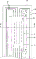
Fig. 1 is a schematic plan view showing one example of an embodiment of a recording head of the present invention.
FIG. 2 is a schematic cross-sectional view of the recording head of FIG. 1 taken along line 2-2 in FIG. 1.
Fig. 3 is a schematic oblique perspective view of the copper foil shown in fig. 1.
Fig. 4 is a schematic plan view showing another example of the embodiment of the recording head of the present invention.
FIG. 5 is a schematic cross-sectional view of the recording head of FIG. 4 taken along line 5-5 in FIG. 4.
Fig. 6 is a schematic plan view showing one example of a flexible printed circuit.
Fig. 7 is a schematic plan view showing another example of the embodiment of the recording head of the present invention.
FIG. 8 is a schematic cross-sectional view of the recording head of FIG. 7 taken along line 8-8 in FIG. 7.
Fig. 9 is a schematic plan view showing another example of the flexible printed circuit.
Fig. 10 is a schematic plan view showing another example of the embodiment of the recording head of the present invention.
FIG. 11 is a schematic cross-sectional view of the recording head of FIG. 10 taken along line 11-11 in FIG. 10.
Fig. 12 is a schematic plan view showing one example of the embodiment of the recording apparatus of the present invention.
Fig. 13 is a schematic sectional view showing a conventional recording head.
Detailed Description
Embodiments of the present invention described below are devices that efficiently dissipate heat generated by a liquid discharge substrate by disposing a foil-shaped heat sink between a support and the liquid discharge substrate, the heat sink having a larger area than a projected area of the liquid discharge substrate with respect to the support. More specifically, a side of the drain substrate mounted on the top of the support faces the outer surface of the support. Therefore, the present invention is directed to improving the heat dissipation efficiency of the device by dissipating heat generated by the liquid discharge substrate over a large area, by disposing a heat dissipation member having a larger area than an outer surface (opposing surface) of the support and an outer surface of the liquid discharge substrate with respect to the outer surface of the support between the opposing surface. In this regard, when the above-described foil-like heat dissipating member having a larger area than the opposing surface is disposed between the support member and the drain substrate, generally, the entire periphery of the heat dissipating member extends to the outside of the drain substrate. However, depending on the relative position or aspect ratio (aspect ratio) of the heat sink with respect to the liquid discharge substrate, there is also a case where a part of the periphery of the heat sink is hidden under the liquid discharge substrate. Of course, as long as the area of the heat sink satisfies the above condition, the object of the present invention can be achieved even if a part of the periphery of the heat sink is hidden under the liquid discharge substrate. Also, as long as the area of the heat sink satisfies the above condition, even in the case where the notch or cut is formed in a part of the heat sink, the object of the present invention can be achieved. Further, the object of the present invention can be achieved even when two or more heat radiating members are provided or one heat radiating member is divided into two or more parts and heat conduction between the two or more heat radiating members is possible as long as the device is a device in which the total area of the heat radiating members satisfies the above-described conditions. Further, although a copper foil is exemplified as the heat sink in each of the following embodiments, the heat sink is not limited to a foil-like member, but may be a sheet-like member having a thickness larger than that of a member generally called a foil. In addition, the material of the heat sink may be a material having at least better thermal conductivity than the adhesive and the support member employed herein. Also, the material of the heat sink may be a material having better thermal conductivity than the liquid discharge substrate.
The liquid discharge substrate is brought into contact with the heat sink by the projections (bump), so that the heat transfer efficiency from the liquid discharge substrate to the heat sink can be improved, and the heat dissipation characteristic can be improved. In addition, the metal film is arranged on the liquid discharge substrate and is contacted with the heat dissipation part through the protrusion, so that the heat conduction efficiency can be improved to a greater extent.
Example 1
Hereinafter, an example of one embodiment of the recording head of the present invention is described with reference to fig. 1 to 3. Fig. 1 is a schematic plan view showing a part of a recording head of the present example, and fig. 2 is a schematic sectional view taken along line 2-2 shown in fig. 1.
As shown in fig. 1 and 2, the recording head of the present example is composed of a support 1 and a liquid discharge substrate 2 mounted on top of the support 1. On the liquid discharge substrate 2, a liquid supply port 12 is formed on the bottom surface 11 of the silicon substrate body 10, a discharge port 14 is formed on the top surface 13 side, a liquid chamber 15 is formed between the liquid supply port 12 and the discharge port 14, and an electrothermal conversion element 16 is formed in the liquid chamber 15. More specifically, the liquid supply port 12 is formed in an elongated form in the longitudinal direction of the substrate main body 10 at the center in the width direction of the bottom surface 11 of the substrate main body 10. Further, on the top surface 13 side of the substrate main body 10, two discharge port rows 14A and 14B are formed, the discharge port rows 14A and 14B respectively including a plurality of discharge ports 14 arranged in a row in the longitudinal direction of the substrate main body 10. As will be understood from fig. 1, each discharge port 14 constituting the discharge port row 14A is shifted by a half pitch (pitch) from each discharge port 14 constituting the other discharge port row 14B. Further, as will be understood from fig. 1, the two discharge port rows 14A and 14B are arranged on both outer sides in the width direction of the liquid supply port 12.
The support member 1 is made of alumina, and as shown in fig. 2, liquid supply holes 22 are formed through from the bottom surface 20 to the top surface 21. The drain substrate 2 is mounted on the top surface 21 of the support 1 by a copper foil 31 functioning as a foil-like heat sink. More specifically, the bottom surface 11 of the liquid discharge substrate 2 is bonded to the top surface 32 of the copper foil 31, and the bottom surface 30 of the copper foil 31 is bonded to the top surface 21 of the support 1. Here, the copper foil 31 has a frame-like planar form, and a substantially rectangular opening 33 (fig. 3) is formed in the center thereof. The inner edge of the opening 33 is sealed by a bonding agent 40 that bonds the top surface 21 of the support 1 to the bottom surface 30 of the copper foil 31 and a bonding agent 41 that bonds the top surface 32 of the copper foil 31 to the bottom surface 11 of the drainage substrate 2. An ink passage 42 is formed between the liquid supply hole 22 and the liquid supply port 12 by a boundary surface of the binders 40 and 41.
The area of the copper foil 31 is larger than the projected area of the liquid discharge substrate 2 with respect to the top surface 21 of the support 1, and as best shown in fig. 1, the peripheral portion of the copper foil 31 extends to the outside of the liquid discharge substrate 2.
According to the recording head of the present example having the above configuration, the heat of the liquid discharge substrate 2 is conducted to the copper foil 31 and diffused through the entire copper foil 31 to be dissipated, and the heat of the liquid discharge substrate 2 is also conducted to the support 1 to be dissipated. More specifically, since the heat of the liquid discharge substrate 2 is diffused through the copper foil 31 having a larger area than the bottom surface 11 of the substrate 2, a heat dissipation characteristic superior to the configuration in which the bottom surface 11 of the liquid discharge substrate 2 is directly bonded to the top surface 21 of the support 1 is realized. Further, in terms of working effect, it will be understood that the material of the heat sink is not limited to copper, but any material may be employed as long as the material is a material having at least better thermal conductivity than the bonding agents 40, 41 and the support member 1. Also, it is preferable that the heat sink is a material having better thermal conductivity than the liquid discharge substrate 2. In addition, similarly, the material of the support 1 is not limited to alumina, and the material of the liquid discharge substrate 2 is not limited to silicon. This also applies to the embodiments described below.
The bonding agent 41 that bonds the bottom surface 11 of the liquid discharge substrate 2 to the top surface 32 of the copper foil 31 has thermal resistance that hinders conduction of heat from the liquid discharge substrate 2 to the copper foil 31. In addition, the bonding agent 40 bonding the bottom surface 30 of the copper foil 31 with the top surface 21 of the support 1 has a thermal resistance that hinders heat conduction from the copper foil 31 to the support 1. Therefore, from the viewpoint of improving the heat dissipation characteristics, it is preferable to reduce the above-mentioned thermal resistance as much as possible by reducing the thickness of the binders 40 and 41 or using a binder having favorable heat dissipation characteristics. For example, the thickness of the binder 40 is preferably 10 μm or less.
Example 2
Hereinafter, another example of the embodiment of the recording head of the present invention is described with reference to fig. 4 and 5. Fig. 4 is a schematic plan view of the recording head of the present example, and fig. 5 is a schematic sectional view taken along line 5-5 in fig. 4. The basic configuration of the recording head of this example is the same as that of embodiment 1. Therefore, components in fig. 4 and 5 which are common to the recording head of embodiment 1 in configuration are denoted by the same reference numerals as embodiment 1, and description of these components is omitted here.
The difference between the recording head of this example and the recording head of embodiment 1 is the bonding configuration between the liquid discharge substrate 2 and the copper foil 31. More specifically, the metal film 50 is formed on the bottom surface 11 of the liquid discharge substrate 2, and the film 50 and the top surface 32 of the copper foil 31 are bonded by a plurality of heat dissipation protrusions 51. As best shown in fig. 4, the film 50 is formed around the periphery of the liquid supply port 12, and the heat dissipation protrusions 51 are formed on the film 50 at substantially uniform intervals.
According to the recording head of the present example having the above configuration, the heat conduction efficiency from the liquid discharge substrate 2 to the copper foil 31 is improved, and more favorable heat dissipation characteristics are obtained. In this regard, in terms of the above-described working effects of the film 50 and the heat dissipation protrusions 51, the materials of the film 50 and the heat dissipation protrusions 51 are not limited to specific materials, and it will be appreciated that any materials may be employed as long as they are materials having better thermal conductivity than the bonding agents 40 and 41. For example, although the material of the thin film 50 is aluminum in this example, the thin film 50 may be formed of gold. Further, although the heat dissipation bumps 51 are solder bumps (solder bumps) in the present example, they may be replaced with gold bumps. Moreover, although the thin film 50 is formed only on a part of the bottom surface 11 of the liquid discharge substrate 2 (the periphery of the liquid supply port 12) according to the present example, the heat dissipation characteristic can be further improved by enlarging the area of the thin film 50 or increasing the number of the heat dissipation protrusions 51.
Example 3
Hereinafter, another example of the recording head embodiment of the present invention is described. The basic configuration of the recording head of this example is the same as that of embodiment 1. The difference between the recording head of the present embodiment and the recording head of embodiment 1 is that a copper foil as a heat sink is formed on a film-like circuit board (hereinafter referred to as "flexible printed circuit") on which wiring patterns for supplying driving signals and the like to the electrothermal conversion elements are formed. Therefore, after a general description of the configuration of the flexible printed circuit constituting the recording head of the present example is given with reference to fig. 6, the configuration of the recording head of the present example will be described with reference to fig. 7 and 8. The support and the liquid discharge substrate constituting the recording head of this example were the same as those in the recording head of embodiment 1. Therefore, the support and the drain substrate are denoted by the same reference numerals as those of embodiment 1 in fig. 7 and 8, and a description thereof is omitted here.
The flexible printed circuit 62 shown in fig. 6 includes a base film (base film)63, a wiring pattern 61 and an electrode terminal 64 formed on the base film 63, and a copper foil 60 formed on the bottom surface of the base film 63. An elongated rectangular hole 65 is formed in the center of the base film 63 in the width direction in the longitudinal direction, and the wiring pattern 61 is formed so as to surround the rectangular hole 65. Electrode terminals 64, each of which is electrically conducted with a corresponding wiring pattern 61, are arranged on both outer sides in the longitudinal direction of the rectangular hole 65 in the width direction of the base film 63 to form electrode rows. Further, an opening 66 communicating with the rectangular hole 65 of the base film 63 is formed in the copper foil 60. In addition, the area of the copper foil 60 is larger than that of the liquid discharge substrate 2 as shown in fig. 7 and 8, so that the heat of the liquid discharge substrate 2 can be dispersed and transferred to the support 1 to dissipate the heat.
Next, the configuration of the recording head of the present example will be described with reference to fig. 7 and 8. Fig. 7 is a schematic plan view showing the recording head of the present example, and fig. 8 is a schematic sectional view taken along line 8-8 in fig. 7. As shown in these figures, in the recording head of the present example, the liquid discharge substrate 2 is mounted on the support 1 via the flexible printed circuit 62 having the above-described configuration. More specifically, the bottom surface of the base film 63 of the flexible printed circuit 62 and the bottom surface 67 of the copper foil 60 are bonded to the top surface 21 of the support 1 by the bonding agent 40, and the bottom surface 11 of the liquid discharge substrate 2 is bonded to the top surface 68 of the copper foil 60 exposed from the rectangular hole 65 by the bonding agent 41. In this regard, each electrode terminal 64 of the flexible printed circuit 62 is connected to a surface electrode 69 formed on the top surface 13 of the liquid discharge substrate 2 by a wire bonding 70.
It is also possible to form a metal film on the bottom surface 11 of the liquid discharge substrate 2 and bond the film to the copper foil 60 by heat dissipating projections. That is, the bonding structure described in embodiment 2 can also be used for the recording head of this example. Further, when an electrode (bottom surface electrode) is provided on the bottom surface of the liquid discharge substrate 2 and the bottom surface electrode is made conductive with the surface electrode 69 by an electrode (penetrating electrode) penetrating the substrate 2, the above-described metal thin film can be used as the bottom surface electrode. For example, the metal film may be used as the bottom surface electrode by connecting the metal film and the through electrode with a bump. At this time, the above-described heat dissipating protrusion may be used as a protrusion for making the metal thin film and the through electrode electrically conductive, or a protrusion for electrical connection may be employed, the protrusion being provided separately from the heat dissipating protrusion.
Further, as shown in fig. 8, when a cover film (cover film) or the like thicker than the copper foil 60 is provided on the bottom surface (the side where the copper foil 60 is formed) of the base film 63 of the flexible printed circuit 62, the bonding agent 41 provided between the bottom surface 67 of the copper foil 60 and the top surface 21 of the support 1 becomes thicker. It will be readily appreciated that the thicker the bonding agent 41 becomes, the greater the resistance to heat conduction from the copper foil 60 to the support 1. Therefore, it is preferable not to provide a cover film on the bottom surface of the base film 63, or even if a cover film is provided, it is preferable that its thickness is a thickness not protruding further to the top surface 21 side of the support 1 than the bottom surface 67 of the copper foil 60.
Example 4
Hereinafter, another embodiment of the recording head of the present invention will be described. The recording head of this example is the same as that of embodiment 3 in that the liquid discharge substrate is mounted on the support via a flexible printed circuit on which a copper foil is formed as a heat sink. The difference between the recording head of this example and the recording head of embodiment 3 is that a plurality of liquid discharge substrates are mounted on a single flexible printed circuit. Therefore, after giving an overall description of the configuration of the flexible printed circuit constituting the recording head of the present example with reference to fig. 9, the configuration of the recording head of the present example will be described with reference to fig. 10 and 11. The configuration of each liquid discharge substrate is the same as that of the liquid discharge substrate 2 constituting the recording head of embodiment 1. Therefore, the liquid discharge substrate is denoted by the same reference numerals as in embodiment 1 in fig. 10 and 11, and a description thereof is omitted here.
The flexible printed circuit 80 shown in fig. 9 includes a base film 81, wiring patterns (not shown in the drawing) formed on both the top and bottom sides of the base film 81 or formed on one side thereof, electrode terminals 82 electrically communicated with the wiring patterns, and copper foils 83a and 83b formed on both the top and bottom sides of the base film 81. In the base film 81, a plurality of elongated rectangular holes 84 are provided in a longitudinal direction in a juxtaposed manner in the width direction, and a plurality of electrode terminals 82 are formed in the longitudinal direction on both outer sides of each rectangular hole 84. These electrode terminals 82 are arranged along the width direction of the base film 81 to form an electrode row, and each electrode terminal 82 is electrically conducted to a wiring pattern not shown in the figure. Openings 85 communicating with each rectangular hole 84 are formed in copper foils 83a and 83b provided on both the top side and the bottom side of the base film 81. The copper foils 83a and 83b penetrate the base film 81 to be connected at two or more positions, and can conduct heat from one side to the other side. Further, as shown in fig. 11, the area of the copper foil 83b is larger than that of the liquid discharge substrate 2, so that the heat of the liquid discharge substrate 2 can be dispersed and transferred to the support 1 to dissipate the heat.
Next, the configuration of the recording head of the present example will be described with reference to fig. 10 and 11. Fig. 10 is a schematic plan view showing a recording head of the present example, and fig. 11 is a schematic cross-sectional view taken along line 11-11 in fig. 10. As shown in these figures, in the recording head of the present example, a plurality of liquid discharge substrates 2 are mounted on a support 1 via a flexible printed circuit 80 having the above-described configuration, and the liquid supply port 12 of each liquid discharge substrate 2 communicates with the liquid supply hole 22 of the support 1 via an ink channel 89. More specifically, the copper foil 83b disposed on the bottom surface of the base film 81 is bonded to the top surface 21 of the support 1 by the bonding agent 86. The copper foil 83a provided on the top surface of the base film 81 is bonded to a metal film 88 through heat dissipation bumps 87, the metal film 88 being provided on the bottom surface 11 of the liquid discharge substrate 2. The ink channel 89 is formed by the boundary surface of the binder 86. The film 88 is the same as the film 50 described in example 2.
In the recording head of the present example having the above configuration, the heat of the liquid discharge substrate 2 is conducted to the copper foil 83a through the film 88 and the heat dissipation protrusions 87 and is diffused and dissipated, and is also conducted to the copper foil 83b to be diffused and dissipated. Further, the heat conducted to the copper foil 83b is also conducted to the support 1 and dissipated.
Example 5
Next, as a fifth embodiment of the present invention, a recording apparatus (ink jet recording apparatus) capable of mounting the above-described type of recording head will be described. Fig. 12 is an explanatory diagram showing one example of a recording apparatus capable of mounting the recording head of the present invention.
In the recording apparatus shown in fig. 12, the recording head H1001 as shown in embodiments 1 to 4 is positioned and mounted on the carriage 102 in an interchangeable manner, and the carriage 102 has an electrical connection portion (not shown) for transmitting a drive signal or the like to the recording head H1001.
The carriage 102 is supported in a guided manner by a guide shaft 103 provided in the main body of the apparatus and extending in the main scanning direction. The carriage 102 can move back and forth along the guide shaft 103. The carriage 102 is driven by a main scanning motor 104 via a driving mechanism including a motor-driven pulley (motored pulley)105, a driven pulley 106, a timing belt 107, and the like, and also thereby controls the position and movement of the carriage 102. The carriage 102 is also equipped with a home position sensor 130. Thus, the apparatus can know the position when the home position sensor 130 on the carriage 102 has passed the locus of the shield 136.
A cap 137 is provided at a carriage position (home position) where the home position sensor 130 detects the shield 136, and the cap 137 seals a face forming the discharge port of the recording head H1001. The cap 137 is used to perform an ink vacuum recovery operation of the recording head by a vacuum member (not shown) via an opening in the cap. The cover 137 is movable by a driving force transmitted via a gear or the like, and can cover a surface on which the discharge port is formed. A cleaning blade 138 is disposed adjacent the cover 137. The apparatus is configured to perform operations of capping, cleaning, and vacuum recovery for a face forming an ink discharge port of the recording head when the carriage 102 has moved to an initial position.
The recording medium 108 such as recording paper or plastic sheet, after being separated into individual sheets, is fed from an automatic sheet feeder (hereinafter referred to as "ASF") 132 by a pickup roller 131, and the pickup roller 131 is rotationally driven by a sheet feeding motor 135. The fed recording medium 108 is conveyed (fed) by a conveying roller 109 through a position (printing portion) facing a discharge port formation surface of the recording head H1001, and the conveying roller 109 is rotated by a driving force of the LF motor 134 transmitted through a gear. At this time, determination as to whether or not the sheet has been fed and confirmation of the start position at the time of sheet feeding are performed when the recording medium 108 passes through the paper end sensor 133. The paper end sensor 133 is also used to determine the actual position of the rear end of the recording medium 108 and to finally determine the current recording position from the actual rear end.
In this regard, the bottom surface of the recording medium 108 is supported by a platen (not shown) so that a flat printing surface is formed at the printing portion. In this case, the recording head H1001 mounted on the carriage 102 is supported such that a face forming a discharge port thereof protrudes downward from the carriage 102 to be parallel to the recording medium 108 between the above-described conveying roller pair.
The recording head H1001 is mounted on the carriage 102 such that the arrangement direction of the discharge ports in each discharge port row is a direction intersecting the scanning direction of the carriage 102 described above, whereby recording is performed by discharging ink from the discharge port rows.
According to the ink jet recording head of each embodiment described in detail above, since the foil-like heat sink having an area larger than the projected area of the liquid discharge substrate with respect to the support is disposed between the support and the liquid discharge substrate, the heat of the liquid discharge substrate is efficiently dissipated by the heat sink and an increase in the substrate temperature is effectively suppressed.
The present application claims priority from japanese patent application No. 2004-.
Claims (5)
1. An ink jet recording head, comprising:
a support including a liquid supply hole; and
a liquid discharge substrate, comprising: a 1 st heat sink formed on one surface of the liquid discharge substrate and composed of a metal film; a liquid supply port communicating with the liquid supply hole; a discharge port formed on the other surface of the liquid discharge substrate, which is the back surface of the one surface, and configured to discharge the liquid supplied from the liquid supply port; and an electrothermal conversion element that generates energy for discharging the liquid from the discharge port; wherein,
the 1 st heat sink is disposed around the periphery of the liquid supply port, one surface of a foil-shaped 2 nd heat sink is coupled to the support, the 1 st heat sink formed on the one surface of the liquid discharge substrate is coupled to a back surface of the one surface of the 2 nd heat sink coupled to the support through a plurality of protrusions provided around the liquid supply port, the 2 nd heat sink has an opening portion communicating with the liquid supply port, and an area of the 2 nd heat sink is larger than a projected area of the liquid discharge substrate with respect to the support.
2. The ink jet recording head according to claim 1, wherein the liquid discharge substrate and the support are bonded by a bonding agent, and a passage is formed between the liquid supply port of the liquid discharge substrate and the liquid supply hole of the support by a boundary surface of the bonding agent.
3. The ink jet recording head according to claim 1, wherein said 2 nd heat dissipating member is a member having a foil-like heat dissipating surface.
4. The ink jet recording head according to claim 1, wherein two or more of said 2 nd heat dissipation members are provided, said two or more 2 nd heat dissipation members being connected together to enable heat conduction therebetween.
5. An inkjet recording apparatus, comprising:
the ink jet recording head according to any one of claims 1 to 4; and
a recording head holder that holds the inkjet recording head at a position facing a recording medium.
Applications Claiming Priority (3)
| Application Number | Priority Date | Filing Date | Title |
|---|---|---|---|
| JP214238/2004 | 2004-07-22 | ||
| JP2004214238 | 2004-07-22 | ||
| PCT/JP2005/013523 WO2006009265A1 (en) | 2004-07-22 | 2005-07-15 | Ink jet recording head and recording apparatus |
Publications (2)
| Publication Number | Publication Date |
|---|---|
| CN101001752A CN101001752A (en) | 2007-07-18 |
| CN101001752B true CN101001752B (en) | 2013-03-20 |
Family
ID=35785371
Family Applications (1)
| Application Number | Title | Priority Date | Filing Date |
|---|---|---|---|
| CN2005800248097A Expired - Fee Related CN101001752B (en) | 2004-07-22 | 2005-07-15 | Inkjet recording head and inkjet recording device |
Country Status (4)
| Country | Link |
|---|---|
| US (1) | US7625072B2 (en) |
| CN (1) | CN101001752B (en) |
| TW (1) | TWI264380B (en) |
| WO (1) | WO2006009265A1 (en) |
Families Citing this family (7)
| Publication number | Priority date | Publication date | Assignee | Title |
|---|---|---|---|---|
| JP2008062568A (en) * | 2006-09-08 | 2008-03-21 | Seiko Epson Corp | Alignment jig and alignment device for liquid jet head |
| US20080079779A1 (en) * | 2006-09-28 | 2008-04-03 | Robert Lee Cornell | Method for Improving Thermal Conductivity in Micro-Fluid Ejection Heads |
| JP5197175B2 (en) * | 2008-06-16 | 2013-05-15 | キヤノン株式会社 | Ink jet recording head and manufacturing method thereof |
| JP6071713B2 (en) | 2012-06-18 | 2017-02-01 | キヤノン株式会社 | Liquid discharge head and liquid discharge apparatus |
| JP6270533B2 (en) | 2014-02-25 | 2018-01-31 | キヤノン株式会社 | Liquid ejection head, recording apparatus, and heat dissipation method for liquid ejection head |
| CN103862865A (en) * | 2014-03-14 | 2014-06-18 | 常熟印刷厂有限公司 | Printed board |
| US10022979B2 (en) | 2016-01-08 | 2018-07-17 | Canon Kabushiki Kaisha | Liquid ejection head, liquid ejection apparatus, and manufacturing method |
Citations (2)
| Publication number | Priority date | Publication date | Assignee | Title |
|---|---|---|---|---|
| CN1136294A (en) * | 1994-10-03 | 1996-11-20 | 罗姆股份有限公司 | Thermal printing head and the clip-type terminal leads and casing used therefor |
| CN1306904A (en) * | 2000-01-21 | 2001-08-08 | 汉欣企业有限公司 | Bubble-actuated inkjet printheads for elastic films |
Family Cites Families (19)
| Publication number | Priority date | Publication date | Assignee | Title |
|---|---|---|---|---|
| US3536868A (en) * | 1969-01-29 | 1970-10-27 | Allen Bradley Co | Reversing switch assembly |
| EP0352726B1 (en) * | 1988-07-26 | 1994-04-27 | Canon Kabushiki Kaisha | Liquid-jet recording head and recording apparatus employing the same |
| US5220345A (en) | 1989-03-31 | 1993-06-15 | Canon Kabushiki Kaisha | Ink jet recording apparatus |
| US5227812A (en) | 1990-02-26 | 1993-07-13 | Canon Kabushiki Kaisha | Liquid jet recording head with bump connector wiring |
| JPH05124187A (en) | 1991-10-31 | 1993-05-21 | Canon Inc | Ink-jet type recorder and its ink drop control method and ink mist absorption method |
| DE69509862T2 (en) | 1994-12-05 | 2000-03-09 | Canon K.K. | Method of manufacturing an ink jet head |
| JP3472042B2 (en) | 1996-07-31 | 2003-12-02 | キヤノン株式会社 | Inkjet recording head |
| US6257703B1 (en) | 1996-07-31 | 2001-07-10 | Canon Kabushiki Kaisha | Ink jet recording head |
| US6464338B1 (en) | 1996-07-31 | 2002-10-15 | Canon Kabushiki Kaisha | Ink jet head with separable tank holding member and recording unit |
| US6137510A (en) | 1996-11-15 | 2000-10-24 | Canon Kabushiki Kaisha | Ink jet head |
| JP3592172B2 (en) | 1999-01-27 | 2004-11-24 | キヤノン株式会社 | Method of manufacturing ink jet recording head, ink jet recording head manufactured by the method, and ink jet recording apparatus equipped with the ink jet recording head |
| US6137452A (en) * | 1999-05-03 | 2000-10-24 | Centurion International, Inc. | Double shot antenna |
| US6536868B1 (en) | 1999-08-24 | 2003-03-25 | Canon Kabushiki Kaisha | Liquid ejection type print head, printing apparatus provided with same and a method for producing a liquid ejection type print head |
| DE60122981T2 (en) | 2000-07-10 | 2007-09-06 | Canon K.K. | Liquid jet recording head cartridge |
| JP2002137410A (en) | 2000-11-02 | 2002-05-14 | Canon Inc | Liquid ejection recording head |
| JP2002254644A (en) | 2001-02-28 | 2002-09-11 | Canon Inc | Liquid discharge method, liquid discharge head, and liquid discharge recording apparatus |
| US6981760B2 (en) | 2001-09-27 | 2006-01-03 | Fuji Photo Film Co., Ltd. | Ink jet head and ink jet printer |
| JP2003170597A (en) | 2001-09-27 | 2003-06-17 | Fuji Photo Film Co Ltd | Ink jet head and ink jet printer |
| JP2004071597A (en) | 2002-08-01 | 2004-03-04 | Renesas Technology Corp | Semiconductor module |
-
2005
- 2005-07-15 CN CN2005800248097A patent/CN101001752B/en not_active Expired - Fee Related
- 2005-07-15 WO PCT/JP2005/013523 patent/WO2006009265A1/en not_active Ceased
- 2005-07-15 US US11/597,417 patent/US7625072B2/en not_active Expired - Fee Related
- 2005-07-20 TW TW094124583A patent/TWI264380B/en not_active IP Right Cessation
Patent Citations (2)
| Publication number | Priority date | Publication date | Assignee | Title |
|---|---|---|---|---|
| CN1136294A (en) * | 1994-10-03 | 1996-11-20 | 罗姆股份有限公司 | Thermal printing head and the clip-type terminal leads and casing used therefor |
| CN1306904A (en) * | 2000-01-21 | 2001-08-08 | 汉欣企业有限公司 | Bubble-actuated inkjet printheads for elastic films |
Non-Patent Citations (3)
| Title |
|---|
| JP特开2002-254644A 2002.09.11 |
| JP特开2004-71597A 2004.03.04 |
| JP特开平10-44420A 1998.02.17 |
Also Published As
| Publication number | Publication date |
|---|---|
| TW200619041A (en) | 2006-06-16 |
| US20080068423A1 (en) | 2008-03-20 |
| TWI264380B (en) | 2006-10-21 |
| WO2006009265A1 (en) | 2006-01-26 |
| CN101001752A (en) | 2007-07-18 |
| US7625072B2 (en) | 2009-12-01 |
Similar Documents
| Publication | Publication Date | Title |
|---|---|---|
| EP1874543B1 (en) | Liquid discharge head, ink jet recording head and ink jet recording apparatus | |
| US7570494B2 (en) | Structure of flexible printed circuit board | |
| CA2288359C (en) | Substrate for use of ink jet head, ink jet head, ink jet cartridge, and ink jet recording apparatus | |
| US20160001573A1 (en) | Thermal head and thermal printer | |
| CN101001752B (en) | Inkjet recording head and inkjet recording device | |
| US8469491B2 (en) | Wiring structure for actuator | |
| EP2769846B1 (en) | Liquid ejection apparatus and connection method for flexible wiring board | |
| CA2415689C (en) | Energy balanced ink jet printhead | |
| AU762871B2 (en) | Droplet deposition apparatus | |
| JP2019166734A (en) | Liquid discharge device | |
| US7025441B2 (en) | Ink jet print head | |
| EP1043158B1 (en) | Ink jet recording head and ink jet recording apparatus | |
| JP7037401B2 (en) | Thermal print head | |
| JP2006056240A (en) | Ink jet recording head and ink jet recording apparatus | |
| CN105408119B (en) | Thermal head and the thermal printer for possessing the thermal head | |
| JP4182911B2 (en) | Recording head | |
| US6935726B2 (en) | Printing head and ink jet printing apparatus which performs printing with the printing head | |
| WO2021200401A1 (en) | Thermal print head and method for manufacturing thermal print head | |
| JP5489550B2 (en) | Recording device | |
| JP2012187838A (en) | Liquid ejecting device | |
| JP3255787B2 (en) | Inkjet recording head | |
| JP2011079246A (en) | Inkjet recording head | |
| JPH11286112A (en) | Inkjet head | |
| JP2017164933A (en) | Liquid discharge device and printer | |
| JP2007320116A (en) | Ink jet recording head and recording apparatus using the same |
Legal Events
| Date | Code | Title | Description |
|---|---|---|---|
| C06 | Publication | ||
| PB01 | Publication | ||
| C10 | Entry into substantive examination | ||
| SE01 | Entry into force of request for substantive examination | ||
| C14 | Grant of patent or utility model | ||
| GR01 | Patent grant | ||
| CF01 | Termination of patent right due to non-payment of annual fee |
Granted publication date: 20130320 Termination date: 20170715 |
|
| CF01 | Termination of patent right due to non-payment of annual fee |