CN100592210C - Projection objective lens of microlithographic projection exposure device - Google Patents
Projection objective lens of microlithographic projection exposure device Download PDFInfo
- Publication number
- CN100592210C CN100592210C CN200480041615A CN200480041615A CN100592210C CN 100592210 C CN100592210 C CN 100592210C CN 200480041615 A CN200480041615 A CN 200480041615A CN 200480041615 A CN200480041615 A CN 200480041615A CN 100592210 C CN100592210 C CN 100592210C
- Authority
- CN
- China
- Prior art keywords
- sub
- projection objective
- projection
- immersion liquid
- sio
- Prior art date
- Legal status (The legal status is an assumption and is not a legal conclusion. Google has not performed a legal analysis and makes no representation as to the accuracy of the status listed.)
- Expired - Fee Related
Links
Images


Classifications
-
- G—PHYSICS
- G03—PHOTOGRAPHY; CINEMATOGRAPHY; ANALOGOUS TECHNIQUES USING WAVES OTHER THAN OPTICAL WAVES; ELECTROGRAPHY; HOLOGRAPHY
- G03F—PHOTOMECHANICAL PRODUCTION OF TEXTURED OR PATTERNED SURFACES, e.g. FOR PRINTING, FOR PROCESSING OF SEMICONDUCTOR DEVICES; MATERIALS THEREFOR; ORIGINALS THEREFOR; APPARATUS SPECIALLY ADAPTED THEREFOR
- G03F7/00—Photomechanical, e.g. photolithographic, production of textured or patterned surfaces, e.g. printing surfaces; Materials therefor, e.g. comprising photoresists; Apparatus specially adapted therefor
- G03F7/70—Microphotolithographic exposure; Apparatus therefor
- G03F7/70216—Mask projection systems
- G03F7/70225—Optical aspects of catadioptric systems, i.e. comprising reflective and refractive elements
-
- G—PHYSICS
- G03—PHOTOGRAPHY; CINEMATOGRAPHY; ANALOGOUS TECHNIQUES USING WAVES OTHER THAN OPTICAL WAVES; ELECTROGRAPHY; HOLOGRAPHY
- G03F—PHOTOMECHANICAL PRODUCTION OF TEXTURED OR PATTERNED SURFACES, e.g. FOR PRINTING, FOR PROCESSING OF SEMICONDUCTOR DEVICES; MATERIALS THEREFOR; ORIGINALS THEREFOR; APPARATUS SPECIALLY ADAPTED THEREFOR
- G03F7/00—Photomechanical, e.g. photolithographic, production of textured or patterned surfaces, e.g. printing surfaces; Materials therefor, e.g. comprising photoresists; Apparatus specially adapted therefor
- G03F7/70—Microphotolithographic exposure; Apparatus therefor
- G03F7/70216—Mask projection systems
- G03F7/70241—Optical aspects of refractive lens systems, i.e. comprising only refractive elements
-
- G—PHYSICS
- G03—PHOTOGRAPHY; CINEMATOGRAPHY; ANALOGOUS TECHNIQUES USING WAVES OTHER THAN OPTICAL WAVES; ELECTROGRAPHY; HOLOGRAPHY
- G03F—PHOTOMECHANICAL PRODUCTION OF TEXTURED OR PATTERNED SURFACES, e.g. FOR PRINTING, FOR PROCESSING OF SEMICONDUCTOR DEVICES; MATERIALS THEREFOR; ORIGINALS THEREFOR; APPARATUS SPECIALLY ADAPTED THEREFOR
- G03F7/00—Photomechanical, e.g. photolithographic, production of textured or patterned surfaces, e.g. printing surfaces; Materials therefor, e.g. comprising photoresists; Apparatus specially adapted therefor
- G03F7/70—Microphotolithographic exposure; Apparatus therefor
- G03F7/70216—Mask projection systems
- G03F7/70341—Details of immersion lithography aspects, e.g. exposure media or control of immersion liquid supply
-
- G—PHYSICS
- G03—PHOTOGRAPHY; CINEMATOGRAPHY; ANALOGOUS TECHNIQUES USING WAVES OTHER THAN OPTICAL WAVES; ELECTROGRAPHY; HOLOGRAPHY
- G03F—PHOTOMECHANICAL PRODUCTION OF TEXTURED OR PATTERNED SURFACES, e.g. FOR PRINTING, FOR PROCESSING OF SEMICONDUCTOR DEVICES; MATERIALS THEREFOR; ORIGINALS THEREFOR; APPARATUS SPECIALLY ADAPTED THEREFOR
- G03F7/00—Photomechanical, e.g. photolithographic, production of textured or patterned surfaces, e.g. printing surfaces; Materials therefor, e.g. comprising photoresists; Apparatus specially adapted therefor
- G03F7/70—Microphotolithographic exposure; Apparatus therefor
- G03F7/708—Construction of apparatus, e.g. environment aspects, hygiene aspects or materials
- G03F7/7095—Materials, e.g. materials for housing, stage or other support having particular properties, e.g. weight, strength, conductivity, thermal expansion coefficient
- G03F7/70958—Optical materials or coatings, e.g. with particular transmittance, reflectance or anti-reflection properties
- G03F7/70966—Birefringence
Landscapes
- Physics & Mathematics (AREA)
- General Physics & Mathematics (AREA)
- Health & Medical Sciences (AREA)
- Engineering & Computer Science (AREA)
- Environmental & Geological Engineering (AREA)
- Epidemiology (AREA)
- Public Health (AREA)
- Lenses (AREA)
- Exposure And Positioning Against Photoresist Photosensitive Materials (AREA)
- Exposure Of Semiconductors, Excluding Electron Or Ion Beam Exposure (AREA)
Abstract
Description
技术领域 technical field
本发明涉及用于制造大规模集成电路及其它微结构元件的微平版印刷(microlithographic)投影曝光装置。更具体地,本发明涉及这种装置的为浸渍操作设计的投影物镜。The present invention relates to microlithographic projection exposure apparatus for the manufacture of large scale integrated circuits and other microstructured elements. More particularly, the invention relates to projection objectives of such devices designed for immersion operations.
背景技术 Background technique
通常通过将多个结构层应用在合适的衬底例如硅晶片上来制造集成电路及其它微结构元件。为了构造所述结构层,首先用对特定波长范围内的光敏感的光致抗蚀剂(photoresist)覆盖所述结构层。然后使被这样覆盖的晶片在投影曝光装置内曝光。在此操作中,利用投影物镜使掩模内包含的结构图案在光致抗蚀剂上成像。由于成像比例通常小于1∶1,所以这种投影物镜常常被称为缩影物镜。Integrated circuits and other microstructural elements are typically fabricated by applying multiple structural layers on a suitable substrate, such as a silicon wafer. To structure the structural layer, the structural layer is first covered with a photoresist that is sensitive to light in a specific wavelength range. The wafer covered in this way is then exposed in a projection exposure apparatus. In this operation, the pattern of structures contained within the mask is imaged on the photoresist using a projection objective. Since the imaging ratio is usually less than 1:1, such projection objectives are often called miniature objectives.
在光致抗蚀剂显象之后,对晶片进行蚀刻或沉淀处理,从而根据掩模上的图案构造最上层。然后,从该层的剩余部分除去残留的光致抗蚀剂。重复进行该过程直到将所有层应用在晶片上。After developing the photoresist, the wafer is etched or deposited to structure the uppermost layer according to the pattern on the mask. The remaining photoresist is then removed from the remainder of the layer. This process is repeated until all layers are applied to the wafer.
投影曝光装置的开发中的一个最主要的设计目标是能够在晶片上平版印刷地限定具有逐渐减小的尺寸的结构。小结构引起高集成密度,这通常对使用这种装置制造的微结构元件的性能具有有利的影响。One of the most important design goals in the development of projection exposure apparatuses is to be able to lithographically define structures with progressively decreasing dimensions on a wafer. Small structures lead to high integration densities, which generally have a favorable effect on the performance of microstructured elements fabricated using such devices.
确定将被平版印刷地限定的结构的最小尺寸的一个最重要的参数是投影物镜的分辨率。由于投影物镜的分辨率随着投影光的波长变短而提高,所以一种实现较小分辨率的方法是使用具有较短波长的投影光。目前使用的最短的波长在深紫外光(DUV)光谱范围内,并且为193nm和157nm。One of the most important parameters determining the minimum size of structures to be lithographically defined is the resolution of the projection objective. Since the resolution of projection objectives increases as the wavelength of the projection light becomes shorter, one way to achieve smaller resolution is to use projection light with a shorter wavelength. The shortest wavelengths currently used are in the deep ultraviolet (DUV) spectral range and are 193nm and 157nm.
另一种降低分辨率的方法是向位于投影物镜的图像侧的末级透镜与待曝光的光致抗蚀剂或另一感光层之间的空间内引入具有高折射率的浸渍液。为浸渍操作设计的并且因此也被称为浸渍透镜的投影物镜可获得大于1例如为1.3或1.4的数值孔径。在此申请的上下文中术语“浸渍液”还应涉及通常被称为“固体浸渍”的物质。在固体浸渍的情况下,浸渍液实际上是固体介质,但是该固体介质没有与光致抗蚀剂直接接触而是与其隔开一定的距离,该距离仅是使用的波长的一小部分。这确保几何光学规律不再适用从而没有发生全反射。Another way of reducing the resolution is to introduce an immersion liquid with a high refractive index into the space between the final lens on the image side of the projection objective and the photoresist or another photosensitive layer to be exposed. Projection objectives which are designed for immersion operations and are therefore also referred to as immersion lenses can achieve numerical apertures greater than 1, for example 1.3 or 1.4. The term "impregnating liquid" in the context of this application shall also relate to what is commonly referred to as "solid impregnating". In the case of solid immersion, the immersion liquid is actually a solid medium, but this solid medium is not in direct contact with the photoresist but is separated from it by a distance that is only a fraction of the wavelength used. This ensures that the laws of geometrical optics no longer apply and total reflection does not occur.
但是,浸渍操作不仅允许实现很高的数值孔径并因此实现较小的分辨率,而且还对聚焦深度具有有利的影响。聚焦深度越高,则对在投影物镜的像面内的晶片的精确定位的要求就越低。除此之外,已发现浸渍操作显著地放宽了某些设计约束,并简化了在数值孔径没有增加的情况下的像差修正。However, the immersion operation not only allows very high numerical apertures and thus low resolutions to be achieved, but also has a favorable influence on the depth of focus. The higher the depth of focus, the lower the requirements for precise positioning of the wafer within the image plane of the projection objective. Among other things, the dipping operation has been found to significantly relax certain design constraints and simplify aberration correction without increasing the numerical aperture.
同时,已开发出这样的浸渍液,其折射率远大于脱离子水的折射率(nH2O=1.43),并且对波长为193nm的投影光是高透明和抵抗性的。当使用具有这种高折射率的浸渍液时,会出现浸渍液的折射率大于构成图像侧的末级光学元件的材料的折射率的情况。在图像侧具有带平面表面的末级光学元件的传统投影物镜内,最大数值孔径受该末级光学元件的折射率限制。如果该光学元件例如由石英玻璃制成,则尽管浸渍液的折射率更高,但是数值孔径的增加不会超过石英玻璃的折射率(nSiO2=1.56)。Meanwhile, an immersion liquid has been developed that has a refractive index much larger than that of deionized water (n H2O = 1.43) and is highly transparent and resistant to projected light with a wavelength of 193 nm. When an immersion liquid having such a high refractive index is used, there are cases where the refractive index of the immersion liquid is larger than that of the material constituting the final optical element on the image side. In conventional projection objectives with a final optic with a planar surface on the image side, the maximum numerical aperture is limited by the refractive index of this final optic. If the optical element is made of quartz glass, for example, the numerical aperture does not increase beyond the refractive index of the quartz glass (n SiO2 =1.56), despite the higher refractive index of the immersion liquid.
文献JP 2000-058436A公开了一种可用于干操作和浸渍操作的具有投影物镜的投影曝光装置。当转换到浸渍操作时,图像侧具有凹面的附加透镜元件被引入投影物镜的末级光学元件与晶片之间的间隙。该附加透镜元件与晶片之间的空隙可充有浸渍液例如油。此文献没有公开浸渍液及附加透镜元件的折射率。The document JP 2000-058436A discloses a projection exposure apparatus with a projection objective lens which can be used in dry operation and immersion operation. When switching over to the dipping operation, an additional lens element with a concave surface on the image side is introduced into the gap between the final optics of the projection objective and the wafer. The space between the additional lens element and the wafer may be filled with an immersion liquid such as oil. This document does not disclose the refractive index of the immersion liquid and the additional lens elements.
发明内容 Contents of the invention
因此,本发明的目的是提供一种浸渍投影物镜,其中图像侧的末级光学元件的折射率小于浸渍液的折射率,但是具有不受末级光学透镜的折射率限制的数值孔径。It is therefore an object of the present invention to provide an immersion projection objective in which the image-side final optics has a refractive index lower than that of the immersion liquid but has a numerical aperture which is not limited by the refractive index of the final optics.
该目的是通过在浸渍操作期间浸渍液朝物面凸出地弯曲来实现的。This object is achieved in that the immersion liquid bends convexly towards the object surface during the immersion operation.
本发明的第一方面提供了一种微平版印刷投影曝光装置的投影物镜,该投影物镜用于使掩模在设置在该投影物镜的像面内的感光层上成像,其中该投影物镜是为其中浸渍液与感光层邻接的浸渍操作设计的,其特征在于,所述浸渍液和在所述投影物镜的图像侧与该浸渍液邻接的介质形成界面,该界面朝所述掩模凸出地弯曲,使得最大曲率半径等于乘积m·s,其中s是该界面和所述像面之间的轴向距离,m是20与120之间的实数。优选地,m在40与100之间。更优选地,m在70与90之间。A first aspect of the present invention provides a projection objective of a microlithographic projection exposure apparatus for imaging a mask on a photosensitive layer arranged in the image plane of the projection objective, wherein the projection objective is An immersion operation in which the immersion liquid adjoins the photosensitive layer is designed, characterized in that the immersion liquid forms an interface with the medium adjacent to the immersion liquid on the image side of the projection objective, which interface is convex towards the mask Curved such that the maximum radius of curvature is equal to the product m·s, where s is the axial distance between the interface and the image plane, and m is a real number between 20 and 120. Preferably, m is between 40 and 100. More preferably, m is between 70 and 90.
所述界面可以朝所述物面凸出地弯曲,使得光线以正弦值在0.5与0.98之间的最大入射角通过该界面。优选地,所述最大入射角的正弦值在0.85和0.95之间。更优选地,所述最大入射角的正弦值在0.87和0.94之间。The interface may be curved convexly towards the object plane such that light rays pass through the interface with a maximum angle of incidence with a sinusoidal value between 0.5 and 0.98. Preferably, the sine of the maximum incident angle is between 0.85 and 0.95. More preferably, the sine of the maximum incident angle is between 0.87 and 0.94.
所述投影物镜可以是具有至少两个成像镜并且其中形成至少两个中间图像的反射折射物镜。The projection objective can be a catadioptric objective having at least two imaging mirrors in which at least two intermediate images are formed.
本发明的第二方面提供了一种用于生产微结构元件的微平版印刷投影曝光装置,其特征在于具有根据本发明第一方面所述的摄影物镜。A second aspect of the invention provides a microlithographic projection exposure apparatus for producing microstructured elements, characterized in that it has a photographic objective according to the first aspect of the invention.
本发明的第三方面提供了一种用于平版印刷地生产微结构元件的方法,包括以下步骤:a)设置衬底,在该衬底上至少部分地应用由感光材料制成的层;b)设置包含待成像的结构的掩模;c)设置包括根据本发明第一方面所述的投影物镜的投影曝光装置;d)利用所述投影曝光装置将所述掩模的至少一部分投影在所述层的区域上。A third aspect of the invention provides a method for lithographically producing microstructured elements, comprising the steps of: a) providing a substrate on which a layer made of photosensitive material is at least partially applied; b ) arranging a mask containing the structure to be imaged; c) arranging a projection exposure apparatus comprising a projection objective according to the first aspect of the invention; d) projecting at least a part of said mask on said projection exposure apparatus using said projection exposure apparatus on the area of the layer described above.
作为浸渍液朝物面凸出地弯曲的结果,投影光线射入邻接介质如图像侧的末级光学元件和浸渍液之间的界面处的入射角减小。因而,可被平面界面全反射的光线现在可有助于图像,这继而可获得更大的数值孔径,该数值孔径还可以大于图像侧的末级光学元件的折射率。这样,数值孔径仅受浸渍液的折射率限制,而不受与物体侧的浸渍液邻接的介质的折射率限制。As a result of the convex bending of the immersion liquid towards the object plane, the angle of incidence of the projection light at the interface between the adjacent medium, for example the image-side final optics, and the immersion liquid is reduced. Thus, light rays that can be totally reflected by the planar interface can now contribute to the image, which in turn allows a larger numerical aperture, which can also be greater than the refractive index of the final optics on the image side. In this way, the numerical aperture is limited only by the refractive index of the immersion liquid and not by the refractive index of the medium adjacent to the immersion liquid on the object side.
实现朝物面凸出地弯曲的浸渍液的最简单的方式是允许浸渍液与投影物镜的末级光学元件的凹入地弯曲的图像侧表面直接邻接。从而,浸渍液的曲率由该表面的曲率不可改变地固定。The simplest way of realizing an immersion liquid that is convexly curved towards the object plane is to allow the immersion liquid to directly adjoin the concavely curved image-side surface of the final optics of the projection objective. Thus, the curvature of the immersion liquid is fixed invariably by the curvature of the surface.
为了防止浸渍液从由末级光学元件的凹入地弯曲的图像侧表面形成的空腔不希望的排出,该表面可被排出阻挡件(drainage barrier)沿用向围绕。该排出阻挡件可以例如是接合到投影物镜的末级光学元件和/或壳体的环。可以例如由诸如石英玻璃或氟化钙(CaF2)的标准透镜材料制成还可以由陶瓷或硬化钢制成的该环优选地在内部具有涂层,该涂层可防止浸渍液被该环污染。如果浸渍液的折射率等于或小于与物体侧的浸渍液邻接的介质的折射率,则这种环也是有利的。In order to prevent undesired drainage of immersion liquid from the cavity formed by the concavely curved image-side surface of the final optical element, this surface can be surrounded along the direction by a drainage barrier. The drain stop may eg be a ring joined to the final optics and/or the housing of the projection objective. The ring, which can be made, for example, of standard lens material such as quartz glass or calcium fluoride (CaF 2 ), but also of ceramic or hardened steel, preferably has a coating on the inside which prevents the immersion liquid from being absorbed by the ring. pollute. Such a ring is also advantageous if the refractive index of the immersion liquid is equal to or lower than the refractive index of the medium adjoining the object-side immersion liquid.
末级光学元件的图像侧表面可以是球面。计算表明曲率半径可有利地选择为此表面与像面之间的轴向距离(即顶点距离)的0.9倍与1.5倍之间并且优选地为1.3倍。这种构型在浸渍液的折射率等于或小于在物体侧与的浸渍液邻接的介质的折射率的情况下也是有利的,这种构型的优点是可避免在浸渍液的物体侧界面处具有大入射角。这种大入射角通常会导致界面对设计和制造缺陷非常敏感。从这一观点出发,入射角应该尽可能小。这通常要求浸渍液的物体侧界面具有非常大的曲率(即小曲率半径)。The image-side surface of the final optics may be spherical. Calculations show that the radius of curvature can advantageously be chosen between 0.9 and 1.5 times and preferably 1.3 times the axial distance between this surface and the image plane (ie the apex distance). This configuration is also advantageous when the refractive index of the immersion liquid is equal to or lower than the refractive index of the medium adjacent to the immersion liquid on the object side, the advantage of this configuration is that it avoids with a large angle of incidence. Such large incident angles often result in very sensitive interfaces to design and fabrication imperfections. From this point of view, the angle of incidence should be as small as possible. This typically requires a very large curvature (ie a small radius of curvature) at the object-side interface of the immersion fluid.
另一种获得浸渍液的朝物面凸出地弯曲的界面的方法是在末级光学元件和浸渍液之间引入中间液。此中间液不能与浸渍液混溶,并且在浸渍操作期间在电场内形成弯曲的界面。这种构型在浸渍液的折射率等于或小于与物体侧的浸渍液邻接的介质的折射率的情况下也是有利的。Another way of achieving a convexly curved interface of the immersion liquid towards the object plane is to introduce an intermediate liquid between the final optics and the immersion liquid. This intermediate liquid is immiscible with the immersion liquid and forms a curved interface within the electric field during the immersion operation. This configuration is also advantageous if the refractive index of the immersion liquid is equal to or lower than the refractive index of the medium adjoining the immersion liquid on the object side.
此方法还利用被称为“电润湿”的作用。如果电场大小改变,则伴随界面的曲率的改变。但是,迄今为止此作用仅用于由法国Varioptic生产的元件上的CCD或CMOS传感器的自动聚焦透镜。This method also utilizes an effect known as "electrowetting". If the magnitude of the electric field changes, it is accompanied by a change in the curvature of the interface. However, so far this effect has only been used for autofocus lenses of CCD or CMOS sensors on components produced by Varioptic of France.
两种液体的电导率之间的差别越大,则界面的曲率越大。如果两种液体之一例如中间液导电而另一种液体例如浸渍液电绝缘,则可实现很大的差别。The greater the difference between the conductivities of the two liquids, the greater the curvature of the interface. A large difference can be achieved if one of the two liquids, for example the intermediate liquid, conducts electricity and the other liquid, for example the immersion liquid, electrically insulates.
此外,如果中间液的密度与浸渍液的密度基本相同则是有利的,这是因为不会出现浮力,并且因此界面的形状与空间上的布置位置无关。Furthermore, it is advantageous if the density of the intermediate liquid is substantially the same as that of the immersion liquid, since buoyancy forces do not occur and the shape of the interface is therefore independent of the spatial arrangement.
中间液的折射率应小于浸渍液的折射率,但是也可小于或大于图像侧的末级光学元件的折射率。The refractive index of the intermediate liquid should be lower than the refractive index of the immersion liquid, but it can also be smaller or larger than the refractive index of the image-side final optics.
优选地,形成弯曲界面所需的电场是通过电极产生的。例如,可通过使用设置在末级光学元件和像面之间的环锥形电极形成对称的界面。这样,界面的曲率可通过改变施加在电极上的电压而连续改变。可应用此措施以修正投影物镜的特定成像性质。Preferably, the electric field required to form the curved interface is generated by electrodes. For example, a symmetrical interface can be formed by using a ring-tapered electrode arranged between the final optics and the image plane. In this way, the curvature of the interface can be continuously changed by varying the voltage applied to the electrodes. This measure can be applied to modify certain imaging properties of projection objectives.
如上所述,希望在浸渍液和与物体侧邻接的介质之间具有强弯曲的界面,因为这可简化成像像差的修正。但是,此界面的曲率小也非常有利。这是因为大曲率通常导致在末级光学元件内形成空腔。这种空腔具有一些缺陷。例如,如果例如出于温度稳定的原因和为了净化液体而必须维持浸渍液流动,则会促使出现不希望的湍流。此外,折射率高的浸渍液的吸附作用稍大于透镜材料。为此,浸渍液内的最大几何路径长度应保持很小。最后,小曲率可简化出于清洁原因而接近末级光学元件的图像侧表面。As mentioned above, it is desirable to have a strongly curved interface between the immersion liquid and the medium adjoining the object side, since this simplifies the correction of imaging aberrations. However, the small curvature of this interface is also very advantageous. This is because large curvatures often lead to the formation of cavities within the final optics. Such cavities have several drawbacks. For example, if the immersion liquid flow has to be maintained, for example for reasons of temperature stabilization and to purify the liquid, undesired turbulence is promoted. In addition, the adsorption of immersion liquid with high refractive index is slightly greater than that of lens material. For this, the maximum geometric path length within the immersion liquid should be kept small. Finally, the small curvature simplifies access to the image-side surface of the final optics for cleaning reasons.
因此,通常优选地,浸渍液和与浸渍液邻接的介质形成朝物面凸出地弯曲的界面,以使得光线以最大入射角通过该界面,该最大入射角的正弦值在0.98与0.5之间,更优选地在0.95与0.85之间,并尤其优选地在0.94与0.87之间。后者的值分别对应于60°和70°的入射角。这里,入射角是指在光线射在表面上的位置处光线和法向平面之间的角度。这些构型在浸渍液的折射率等于或小于与物体侧的浸渍液相邻的介质的折射率的情况下也是有利的。Therefore, it is generally preferred that the immersion liquid and the medium adjoining the immersion liquid form an interface that is convexly curved towards the object plane, so that light rays pass through this interface with a maximum angle of incidence, the sine of which is between 0.98 and 0.5 , more preferably between 0.95 and 0.85, and especially preferably between 0.94 and 0.87. The latter values correspond to angles of incidence of 60° and 70°, respectively. Here, the angle of incidence refers to the angle between the ray and the normal plane at the position where the ray hits the surface. These configurations are also advantageous if the refractive index of the immersion liquid is equal to or lower than the refractive index of the medium adjacent to the immersion liquid on the object side.
根据本发明可行的例如可以为1.6和更大的非常大的数值孔径在某些情况下需要投影物镜的新颖设计。在这一点,包括至少两个成像镜并且其中形成至少两个中间图像的反射折射投影物镜是有利的。这种构型在浸渍液的折射率等于或小于与物体侧的浸渍液的邻接的介质的折射率的情况下也是有利的。Very large numerical apertures, which are possible according to the invention, for example 1.6 and larger, in some cases require novel designs of the projection objective. In this regard, a catadioptric projection objective comprising at least two imaging mirrors and in which at least two intermediate images are formed is advantageous. This configuration is also advantageous when the refractive index of the immersion liquid is equal to or lower than the refractive index of the medium adjoining the immersion liquid on the object side.
附图说明 Description of drawings
结合附图参考下文的详细说明可更容易地理解本发明的各个特征和优点,在附图中:The various features and advantages of the present invention may be more readily understood by reference to the following detailed description when taken in conjunction with the accompanying drawings, in which:
图1以不按比例的非常简化的视图示出通过具有根据本发明的投影物镜的投影曝光装置的子午线部分;FIG. 1 shows, in a very simplified view not to scale, a meridian section through a projection exposure apparatus with a projection objective according to the invention;
图2示出图1中所示的投影物镜的图像侧端部的放大视图;Figure 2 shows an enlarged view of the image-side end of the projection objective shown in Figure 1;
图3示出具有排出阻挡件的可选实施例的类似于图2的放大视图;FIG. 3 shows an enlarged view similar to FIG. 2 of an alternative embodiment with a vent stop;
图4示出根据另一个示例性实施例的投影物镜的图像侧端部,在该实施例中在浸渍液和图像侧的末级光学元件之间引入中间液;4 shows the image-side end of a projection objective according to another exemplary embodiment, in which an intermediate liquid is introduced between the immersion liquid and the image-side final optical element;
图5示出根据本发明的投影物镜的图像侧端部处的几何条件的细节;Figure 5 shows a detail of the geometrical conditions at the image-side end of a projection objective according to the invention;
图6示出通过根据本发明的一实施例的反射折射投影物镜的子午线部分;Figure 6 shows a meridian section through a catadioptric projection objective according to an embodiment of the invention;
图7示出通过根据本发明的另一实施例的反射折射投影物镜的子午线部分;Figure 7 shows a meridian section through a catadioptric projection objective according to another embodiment of the invention;
图8示出通过根据本发明的又一实施例的反射折射投影物镜的子午线部分;Figure 8 shows a meridian section through a catadioptric projection objective according to yet another embodiment of the invention;
图9示出通过根据本发明的再一实施例的反射折射投影物镜的子午线部分。Figure 9 shows a meridian section through a catadioptric projection objective according to yet another embodiment of the invention.
具体实施方式 Detailed ways
图1以不按比例的非常简化的视图示出通过总体由110指示的微平版印刷投影曝光装置的子午线部分。投影曝光装置110包括用于产生投影光113的照射系统112,该系统包括光源114、照射光学器件116和光阑118。在所示的示例性实施例中,投影光113的波长为193nm。FIG. 1 shows a meridian section through a microlithographic projection exposure apparatus generally indicated at 110 in a very simplified view not to scale.
投影曝光装置110还包括投影物镜120,该投影物镜包括多个透镜元件,为了清楚起见,在图1中仅作为示例示出一些透镜元件并用L1到L5指示。投影物镜120使设置在该投影物镜120的物面122内的掩模124以减小的比例在感光层126上成像。可由光致抗蚀剂构成的感光层126设置在投影物镜120的像面128内并应用在衬底130上。如本领域内已知的,感光层126本身可由多个层构成并且还可包括抗反射层。The
浸渍液134被引入图像侧的末级透镜元件L5和感光层126之间的间隙132内。An
这可从图2中更清楚地看到,该图放大地示出投影物镜120的图像侧端部。图像侧的末级透镜元件L5在图像侧具有凹入地弯曲的表面136。图像侧的末级透镜元件L5和感光层126之间的间隙132(通常在两端是平的)现在转化成一空腔。This can be seen more clearly in FIG. 2 , which shows the image-side end of
表面136大致为球壳形状,其曲率半径在图2中用R指示。在此布置中,曲率半径R大约为图像侧的末级透镜元件L5和感光层126之间的轴向距离的1.3倍。
浸渍液134的折射率nL大于构成图像侧的末级透镜元件L5的材料的折射率n1。例如,如果使用石英玻璃或氟化钙作为该末级透镜元件L5的材料,则应选择折射率nL高于1.56或1.5的浸渍液。如互联网网页www.eetimes.com/semi/news/OEG2004128S0017所述,这可通过例如在水中添加硫酸盐、碱金属例如铯、或磷酸盐来实现。这些浸渍液即使在深紫外光光谱范围内的波长下仍具有足够的透明性和稳定性。如果投影曝光装置110是为较长的波长例如可见光光谱范围内的波长设计的,则也可使用传统的具有高折射率的浸渍液例如雪松油、二硫化碳或一溴代萘(monobromonaphthalene)作为浸渍液。The refractive index n L of the
由于浸渍液相对于物面122与图像侧的末级透镜元件L5形成凸出地弯曲界面139,所以在所述界面139处仅出现较小的光束入射角。这在图2中作为示例由具有最大孔径角α的孔径射线113a和113b示出。结果,在所述界面处的反射损失相应地较小。因此,相对于投影物镜120的光轴OA具有大孔径角的射线也可有助于形成掩模124的像,结果可通过投影物镜120实现达到浸渍液134的折射率nL的数值孔径。另一方面,如果如现有技术内的通常情况界面139是平面,则所述射线将在末级透镜元件L5和浸渍液之间的界面处被全部反射。Since the immersion liquid forms a convexly
图3以与图2类似的视图示出根据另一示例性实施例的投影物镜120。在该图中相同的部分用相同的标号指示。FIG. 3 shows a
投影物镜120’与图1和2中所示的投影物镜120的不同之处仅在于一环140紧密地接合到投影物镜120的末级透镜元件L5和壳体141。环140用作浸渍液134的排出阻挡件。如果图像侧的末级透镜元件L5的表面136很强地弯曲从而间隙132具有很大的沿光轴OA的最大延伸长度,则这种排出阻挡件尤其有利。因此,浸渍液134的静水压力较高。在没有排出阻挡件时,所述压力可最终导致这样的结果,即浸渍液134被从空腔挤出到投影物镜120和感光层126之间的周围间隙132,从而周围气体会进入该空腔。Projection objective 120' differs from
环140可由例如诸如石英玻璃或氯化钙的标准透镜材料制成,但是也可由诸如InvarTM镍合金、不锈钢或(玻璃)陶瓷的其它材料制成。The
图4示出根据另一示例性实施例的投影物镜120”的图像侧端部,在该实施例中浸渍液134的弯曲以另一种方式实现。FIG. 4 shows the image-side end of a
在投影物镜120”内,浸渍液134并没有与图像侧的末级透镜元件L5”直接邻接。相反,在图像侧的末级透镜元件L5”和浸渍液134之间设置有另一种液体,该液体在下文被称为中间液142。中间液142在所示的实施例中是已添加有离子的水。该水因离子而变得具有导电性。在此情况下折射率大于末级透镜元件L5”的浸渍液134是电绝缘的。对于在可见光光谱范围内的投影光的波长,例如上文提到的油和萘适于用作浸渍液134。In
中间液142完全充满图像侧的末级透镜元件L5”的图像侧表面136”和浸渍液134之间的空间。表面136”在所示的示例性实施例中凸出地弯曲,但是该表面也可以是平面。与如上述示例性实施例中所述的具有排出阻挡件功能的环140”邻接地设置有类似的环锥形电极146,该电极连接到可控电压源147。一隔离层148应用在锥形电极146上,该隔离层与感光层126一起确保浸渍液134相对于像面连续的隔离。电压源147产生频率在100kHz与500kHz之间的交流电压。应用于锥形电极146的电压的幅值大约为40V。The
当向锥形电极146施加交流电压时,已知的电润湿作用具有这样的结果,即浸渍液134和中间液142之间的界面139朝物面122凸出地弯曲。此弯曲的原因是毛细管力,如果在电极146上施加足够大的交流电压,则毛细管力与总容积的不可变性和将形成最小表面的倾向性一起导致非常近似地生成球形界面139。The known electrowetting effect has the result that the
如果交流电压降低,则界面139的曲率减小。在图4中这由如虚线所示的界面139’指示。因此,可以简单的方式即通过改变施加在锥形电极146上的交流电压,连续改变由浸渍液134形成的液体透镜的折射率。为了完整起见,还应提到在此处界面139的弯曲不一定需要交流电压,也可通过直流电压实现。If the AC voltage decreases, the curvature of
另外,在此实施例中,朝物面122凸出地弯曲的浸渍液134的界面具有这样的作用,即可实现数值孔径不受末级透镜元件L5”的折射率限制而是仅受浸渍液134的折射率限制。Furthermore, in this embodiment, the interface of the
由浸渍液134形成的液体透镜的屈光力的连续可变性也可有利地用在投影物镜内的其它位置。有利地,这种液体透镜可用在投影物镜内暴露在特别高的光强度下的位置。这样可抑制或至少通过仅替换浸渍液来补救例如在传统固体透镜的情况下发生的劣化现象。顺便提及,对应的解释也可应用于图2和3中所示的实施例。The continuous variability of the optical power of the liquid lens formed by the
图5示出根据又一示例性实施例的投影物镜的图像侧端部。这里,末级透镜元件L205具有朝向像面的球面236,与图2和3中所示实施例的透镜元件L5相比,该球面的凹曲率较小,即曲率半径R较大。下文将更详细地说明末级透镜元件L205和浸渍液134之间的界面的几何条件。Fig. 5 shows an image-side end of a projection objective according to yet another exemplary embodiment. Here, final lens element L205 has a
标号AR指示具有最大孔径角
投影物镜的基本特征是两个量即图像侧的数值孔径
可从图像侧的数值孔径NA得到确保光可传播通过末级透镜元件和浸渍液而不会在该界面被反射的特定几何特性。但是,对于末级透镜元件的设计要求实际上比可仅从图像侧的数值孔径得到的要求更严格些。例如,入射角α应不超过特定值,例如大约75°,并更优选地70°。这是因为经验显示,具有较大入射角α的投影物镜要求非常复杂的措施来实现良好的像差修正和降低对制造公差和变化的环境条件的敏感性。From the numerical aperture NA on the image side can be derived the specific geometrical properties that ensure that light can propagate through the final lens element and immersion liquid without being reflected at this interface. However, the design requirements for the final lens element are actually more stringent than can be obtained from the numerical aperture on the image side alone. For example, the angle of incidence α should not exceed a certain value, such as about 75°, and more preferably 70°. This is because experience has shown that projection objectives with larger angles of incidence α require very complex measures to achieve good aberration correction and reduce sensitivity to manufacturing tolerances and changing environmental conditions.
目前用于干操作的投影物镜实现接近大约0.95的图像侧NA。这意味着数值孔径NA不会超过就在像面前方的介质(通常是气体或气体的混合物例如空气)的折射率的95%。在这种干投影物镜内,尤其是在接近像面的最后表面处以及透镜元件的其它表面处,最大入射角为大约70°。Current projection objectives for dry operation achieve an image-side NA close to about 0.95. This means that the numerical aperture NA does not exceed 95% of the refractive index of the medium (usually a gas or a mixture of gases such as air) immediately in front of the image plane. In such dry projection objectives, especially near the rearmost surface of the image plane and at other surfaces of the lens element, the maximum angle of incidence is about 70°.
由于这些考虑也应用于浸液物镜,所以入射角应保持低于这些值。从几何考虑可清楚地看到,表面236的弯曲越强,则入射角越小。因此,强的弯曲可确保入射角不超过这些值。Since these considerations also apply to immersion objectives, the angle of incidence should be kept below these values. It is clear from geometrical considerations that the more curved the
另一方面,透镜元件L205的表面236不应过于严重地弯曲。这是因为过于严重的弯曲会导致浸渍液134的与流体动力学、污染和温度敏感性有关的问题加重。例如,难以使浸渍液134的温度均匀和恒定,并且浸渍液134会以这样的方式被封闭在强凸出的空腔内,使得例如出于清洗原因替换浸渍液的任务变得非常复杂。On the other hand,
已发现如果最大入射角α满足以下条件则可实现很好的折衷:It has been found that a good compromise can be achieved if the maximum angle of incidence α satisfies the following conditions:
0.95>sin(α)>0.850.95>sin(α)>0.85
在下文得到指定合适的曲率ρ的公式,该曲率是距离s、图像高度h以及末级透射元件L205的折射率n’和浸渍液134的折射率n的函数,从而入射角α的正弦值不会超过特定的有利和可实用的值。已发现该值为sin(α)<κ,其中κ=0.95。使用折射定律,其遵循The formula for specifying a suitable curvature ρ is given below, which is Functions of the distance s, the image height h, and the refractive index n' of the final transmission element L205 and the refractive index n of the
根据简单的几何考虑,可从上式推导出According to simple geometric considerations, it can be deduced from the above formula that
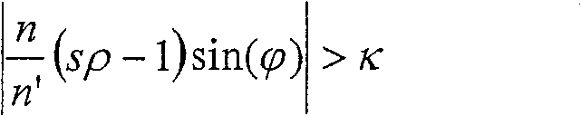
从而,thereby,
是最小表面曲率的条件。对于半径R=1/ρ,这给出is the minimum surface curvature condition. For radius R=1/ρ, this gives
对于示例性的数值孔径NA=1.5,并使用n’=1.56的SiO2作为末级透镜元件L205的材料,这导致For an exemplary numerical aperture NA = 1.5, and using SiO2 with n' = 1.56 as material for the final lens element L205, this results in
R>m·sR>m·s
其中m≈83。对于s=2mm,这使得对于最大曲率半径,半径R大约为167mm。where m≈83. For s = 2mm, this results in a radius R of approximately 167mm for the largest radius of curvature.
另外,如果在有限像场的情况下考虑最外部的图像点的孔径射线,则为此在上面的公式内用根据下式的s’In addition, if the aperture ray of the outermost image point is considered in the case of a limited image field, s' according to the following formula is used for this in the above formula
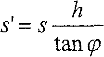
替换距离s。对于最大场高度h,然后最小曲率ρ遵循下式:Replacement distance s. For the maximum field height h, then the minimum curvature ρ follows:
如果以具有上述参数即NA=1.5以及n’=1.56的投影物镜开始,并且还假设最大场高度h为15mm,则最大曲率半径R应小于m=83乘以(s-5.57mm)。对于s=8mm,这导致大约为200mm的最大曲率半径R,而对于s=10mm,R大约为375mm。If starting with a projection objective with the above parameters, NA = 1.5 and n' = 1.56, and also assuming a maximum field height h of 15mm, the maximum radius of curvature R should be less than m = 83 times (s - 5.57mm). For s=8mm this results in a maximum radius of curvature R of approximately 200mm and for s=10mm R of approximately 375mm.
例如,如果κ选为0.95并且使用折射率n=1.43的浸渍液,则可通过用由SiO2制成的、与像面的距离s=2mm并且最大曲率半径小于大约80mm的末级透镜元件L205,实现数值孔径NA=1.35。如果表面的最大半径不仅低于给定值而且还至少基本上等于这些值,则可使上述在大曲率的情况下出现的有害影响最小。For example, if κ is selected as 0.95 and an immersion liquid with a refractive index n=1.43 is used, the final lens element L205 made of SiO 2 with a distance of s=2mm from the image plane and a maximum radius of curvature smaller than about 80mm can be used , to achieve a numerical aperture NA = 1.35. The above-mentioned detrimental effects occurring in the case of large curvatures can be minimized if the maximum radius of the surface is not only below the given values but also at least substantially equal to these values.
除了如上文所述最大入射角不应超过特定的上限和下限之外,应确保在从像面上的一点朝物面看时光线相当快地收敛。否则需要具有非常大的直径的光学元件。此定性设计规则可按以下方式在数学上表示:如果k、l、m是孔径射线的三个方向余弦而n是介质内的折射率,同时k2+l2+m2=n2,则在其中(k2+l2)/n2>K0的物镜内(尤其是在像面附近)不应有容积。限值K0应选择为K0=0.95或更好地K0=0.85。In addition to the fact that the maximum angle of incidence should not exceed certain upper and lower limits as stated above, it should be ensured that the rays converge fairly quickly when looking from a point on the image plane towards the object plane. Otherwise optical elements with very large diameters are required. This qualitative design rule can be expressed mathematically as follows: If k, l, m are the three direction cosines of aperture rays and n is the refractive index in the medium, and k 2 +l 2 +m 2 =n 2 , then There should be no volume in objectives where (k 2 +l 2 )/n 2 >K 0 , especially near the image plane. The limit value K 0 should be chosen as K 0 =0.95 or better K 0 =0.85.
图6示出通过图1和2中所示的投影物镜120的第一示例性实施例的子午线部分。该投影物镜的设计数据在表1中列出;半径和厚度均以毫米为单位。在投影物镜上的数字针对光学元件的被选择的表面。以短条组为特征的表面非球面地弯曲。所述表面的曲率用以下非球面公式说明:FIG. 6 shows a meridian section through the first exemplary embodiment of the
在此等式内,z是平行于光轴的各个面的弧矢,h是距离光轴的径向距离,c=1/R是在各个面的顶点处的曲率,其中R是曲率半径,k是圆锥常数而A、B、C、D、E和F是表2中列出的非球面常数。在该示例性实施例中,球面常数k等于0。In this equation, z is the sagittal of each face parallel to the optical axis, h is the radial distance from the optical axis, c=1/R is the curvature at the vertex of each face, where R is the radius of curvature, k is the conic constant and A, B, C, D, E, and F are the aspheric constants listed in Table 2. In this exemplary embodiment, the spherical constant k is equal to zero.
投影物镜120包含两个非球面镜S1和S2,在这两个镜之间生成两个(没有被最佳地修正的)中间图像。投影物镜120针对193nm的波长以及折射率nL为1.60的浸渍液设计。投影物镜120的线性放大率为β=-0.25并且数值孔径为NA=1.4。但是,一些额外改进使得可容易地实现刚好达到浸渍液的折射率并因此仅稍小于1.6的数值孔径NA。
图7至9示出通过图1和图2中所示的投影物镜120的另外三个示例性实施例的子午线部分。图7中所示的投影物镜的设计数据和非球面常数在表3和4中列出;表5、6和表7、8分别列出图8和图9中所示实施例的设计数据和非球面常数。7 to 9 show meridian sections through three further exemplary embodiments of the
图7至9中所示的投影物镜均具有NA=1.40的图像侧数值孔径和折射率nL=1.60的的浸渍液。因此,此折射率总是大于由CaF2制成的末级透镜元件的折射率,即nL>nCaF2。The projection objectives shown in FIGS. 7 to 9 each have an image-side numerical aperture of NA = 1.40 and an immersion liquid with a refractive index nL = 1.60. Therefore, this refractive index is always greater than that of the final lens element made of CaF2 , ie n L >n CaF2 .
图7中所示的针对波长λ=193nm设计的投影物镜未被消色差并具有末级透镜元件LL7,该末级透镜元件具有形成一种用于浸渍液134的空腔的强凹入地弯曲的图像侧表面。波阵面被修正为大约2/100λ。The projection objective designed for the wavelength λ=193 nm shown in FIG. 7 is not achromatized and has a final lens element LL7 with a strongly concave curvature forming a cavity for the
图8中所示的投影物镜是针对波长λ=157nm设计的并且被消色差。末级透镜元件LL8的图像侧表面更强地凹入地弯曲;除此之外,曲率半径与末级透镜元件LL8与像面之间的轴向距离基本相等,即曲率中心基本上位于像面内。结果,浸渍液134具有很大的最大厚度。尽管在λ=157nm下CaF2的折射率大约为nCaF2=1.56,但是仍假设浸渍液的折射率较大(nL=1.60)。波阵面被修正为大约4/100λ。The projection objective shown in Fig. 8 was designed for the wavelength λ = 157 nm and was achromatized. The image-side surface of the final lens element LL8 is more concavely curved; in addition, the radius of curvature is substantially equal to the axial distance between the final lens element LL8 and the image plane, i.e. the center of curvature is substantially at the image plane Inside. As a result, the
图9中所示的投影物镜是针对波长λ=193nm设计的并且未被消色差。末级透镜元件LL9的图像侧表面仅具有较小的凹曲率,从而浸渍液934基本形成平面层。曲率半径远大于末级透镜元件LL9与像面之间的轴向距离(大约为10倍),即曲率中心与像面之间具有很大的距离。在末级透镜元件LL9和浸渍液934之间的界面处的最大入射角为大约67°(即sinα=0.92)。波阵面被修正为大约5/100λ。The projection objective shown in Fig. 9 was designed for the wavelength λ = 193 nm and was not achromatized. The image-side surface of the final lens element LL9 has only a small concave curvature, so that the immersion liquid 934 essentially forms a planar layer. The radius of curvature is much larger than the axial distance (about 10 times) between the final lens element LL9 and the image plane, that is, there is a large distance between the center of curvature and the image plane. The maximum angle of incidence at the interface between the last lens element LL9 and the immersion liquid 934 is about 67° (ie sin α=0.92). The wavefront is corrected to approximately 5/100λ.
当比较在图7和图9中所示类似实施例中的波阵面误差时,可清楚地看到,图7中末级透镜元件LL7的图像侧表面具有较大曲率的设计允许实现更好的波阵面修正(2/100λvs.5/100λ)。但是,尽管图9中所示的投影物镜没有如图7中所示的投影物镜那样好地被校正,但由于比较大的曲率半径,在末级透镜元件LL9之下仅存在小空腔,根据上述原因这是有利的。When comparing the wavefront errors in similar embodiments shown in Fig. 7 and Fig. 9, it can be clearly seen that the design of the image-side surface of the final lens element LL7 in Fig. 7 with a larger curvature allows better Wavefront correction (2/100λvs.5/100λ). However, although the projection objective shown in FIG. 9 is not as well corrected as the projection objective shown in FIG. This is advantageous for the above reasons.
当然,本发明并不局限于如上所述的用于反射折射投影物镜。本发明还可有利地用于具有数量比所示实施例少或多的中间图像的投影物镜,以及具有或不具有中间图像的折射投影物镜。另外,光轴也可延伸通过像场的中心。例如可在US 2002/0196533 A1、WO 01/050171 A1,WO 02/093209A2和US 6496306 A中发现另外的合适的透镜设计的示例。Of course, the invention is not limited to use with catadioptric projection objectives as described above. The invention is also advantageously applicable to projection objectives with a fewer or greater number of intermediate images than in the illustrated embodiment, and to refractive projection objectives with or without intermediate images. Alternatively, the optical axis may extend through the center of the image field. Further examples of suitable lens designs can be found, for example, in US 2002/0196533 A1, WO 01/050171 A1, WO 02/093209 A2 and US 6496306 A.
表1:设计数据Table 1: Design Data
表2:非球面常数Table 2: Aspherical Constants
表面4 表面5 表面10Surface 4 Surface 5 Surface 10
A 5,36225288E-08 A 2,53854010E-08 A 4,51137087E-07A 5,36225288E-08 A 2,53854010E-08 A 4,51137087E-07
B -5,17992581E-12 B -1,22713179E-11 B 2,46833840E-11B -5,17992581E-12 B -1,22713179E-11 B 2,46833840E-11
C 8,49599769E-16 C 1,21417341E-15 C 5,78496960E-15C 8,49599769E-16
D -7,57832730E-20 D -1,92474180E-19 D -4,39101683E-18D -7,57832730E-20 D -1,92474180E-19 D -4,39101683E-18
E 3,59228710E-24 E 2,08240691E-23 E -5,64853356E-22E 3,59228710E-24 E 2,08240691E-23 E -5,64853356E-22
F -9,16722201E-29 F -9,29539601E-28 F 4,95744749E-26F -9,16722201E-29 F -9,29539601E-28 F 4,95744749E-26
表面14 表面18 表面19Surface 14 Surface 18 Surface 19
A -8,48905023E-09 A 1,04673033E-08 A -4,11099367E-09A -8,48905023E-09
B 1,45061822E-13 B 1,34351117E-13 B -9,91828838E-14
C -6,34351367E-18 C 1,03389626E-18 C -7,93614779E-19C -6,34351367E-18
D 2,84301572E-22 D 5,16847878E-23 D -1,66363646E-22D 2,84301572E-22 D 5,16847878E-23 D -1,66363646E-22
E -8,24902650E-27 E -1,23928686E-27 E 5,56486530E-27E -8,24902650E-27 E -1,23928686E-27 E 5,56486530E-27
F 1,27798308E-31 F 3,09904827E-32 F -1,79683490E-31
表面20 表面23 表面26Surface 20 Surface 23 Surface 26
A 1,14749646E-07 A -2,87603531E-08 A -4,35420789E-08A 1,14749646E-07 A -2,87603531E-08 A -4,35420789E-08
B -8,19248307E-12 B -9,68432739E-12 B -6,70429494E-13B -8,19248307E-12 B -9,68432739E-12 B -6,70429494E-13
C 8,78420843E-16 C 6,88099059E-16 C -4,05835225E-17C 8,78420843E-16 C 6,88099059E-16 C -4,05835225E-17
D -1,39638210E-19 D -8,70009838E-20 D -1,10658303E-20D -1,39638210E-19 D -8,70009838E-20 D -1,10658303E-20
E 2,09064504E-23 E 9,59884320E-24 E 4,80978147E-25E 2,09064504E-23 E 9,59884320E-24 E 4,80978147E-25
F -2,15981914E-27 F -5,07639229E-28 F -5,35014389E-29F -2,15981914E-27 F -5,07639229E-28 F -5,35014389E-29
表面28 表面31 表面35Surface 28 Surface 31 Surface 35
A -2,70754285E-08 A 4,38707762E-09 A 1,73743303E-08A -2,70754285E-08 A 4,38707762E-09
B -1,36708653E-12 B -3,69893805E-13 B 1,60994523E-12B -1,36708653E-12 B -3,69893805E-13
C -2,46085956E-17 C -4,93747026E-18 C -1,71036162E-16C -2,46085956E-17 C -4,93747026E-18 C -1,71036162E-16
D 2,26651081E-21 D 4,05461849E-22 D 1,26964535E-20D 2,26651081E-21 D 4,05461849E-22
E -1,20009586E-25 E -7,59674606E-27 E -5,77497378E-25E -1,20009586E-25 E -7,59674606E-27 E -5,77497378E-25
F 9,28622501E-30 F 5,58403314E-32 F 1,55390733E-29F 9,28622501E-30 F 5,58403314E-32
G -1,78430224E-34G -1,78430224E-34
表面37Surface 37
A 1,04975421E-07A 1,04975421E-07
B 1,94141448E-11
C -2,31145732E-15C -2,31145732E-15
D 4,57201996E-19D 4,57201996E-19
E -3,92356845E-23E -3,92356845E-23
F 2,35233647E-27F 2,35233647E-27
表3:设计数据Table 3: Design Data
表4:非球面常数Table 4: Aspherical Constants
表面 3 19 24 28 30Surface 3 19 24 28 30
K 0 0 0 0 0K 0 0 0 0 0 0 0
A 4.047232E-09 -4.175853E-08 -3.889430E-08 6.661869E-09 6.661869E-09A 4.047232E-09 -4.175853E-08 -3.889430E-08 6.661869E-09 6.661869E-09
B 8.449241E-13 -5.621416E-13 2.260825E-13 2.899240E-13 2.899240E-13B 8.449241E-13 -5.621416E-13 2.260825E-13 2.899240E-13 2.899240E-13
C 5.603175E-17 -2.909466E-19 9.880822E-18 -1.932302E-17 -1.932302E-17C 5.603175E-17 -2.909466E-19 9.880822E-18 -1.932302E-17 -1.932302E-17
D -4.004583E-21 3.690043E-22 -2.672567E-22 1.602360E-21 1.602360E-21D -4.004583E-21 3.690043E-22 -2.672567E-22 1.602360E-21 1.602360E-21
E -8.168767E-25 2.119217E-26 4.717688E-26 -6.342246E-26 -6.342246E-26E -8.168767E-25 2.119217E-26 4.717688E-26 -6.342246E-26 -6.342246E-26
F 2.123279E-29 -9.535588E-31 -3.817055E-30 1.183564E-30 1.183564E-30F 2.123279E-29 -9.535588E-31 -3.817055E-30 1.183564E-30 1.183564E-30
表面 34 39 44 46 52Surface 34 39 44 46 52
K 0 0 0 0 0K 0 0 0 0 0 0 0
A -3.889430E-08 -2.037803E-08 -1.157857E-08 -1.157857E-08 -2.037803E-08A -3.889430E-08 -2.037803E-08 -1.157857E-08 -1.157857E-08 -2.037803E-08
B 2.260825E-13 -6.612137E-13 1.455623E-12 1.455623E-12 -6.612137E-13B 2.260825E-13 -6.612137E-13 1.455623E-12 1.455623E-12 -6.612137E-13
C 9.880822E-18 2.840028E-17 -5.746524E-17 -5.746524E-17 2.840028E-17C 9.880822E-18 2.840028E-17 -5.746524E-17 -5.746524E-17 2.840028E-17
D -2.672567E-22 -4.931922E-21 1.261354E-21 1.261354E-21 -4.931922E-21D -2.672567E-22 -4.931922E-21 1.261354E-21 1.261354E-21 -4.931922E-21
E 4.717688E-26 4.142905E-25 4.054615E-25 4.054615E-25 4.142905E-25E 4.717688E-26 4.142905E-25 4.054615E-25 4.054615E-25 4.142905E-25
F -3.817055E-30 -1.562251E-29 -2.761361E-29 -2.761361E-29 -1.562251E-29F -3.817055E-30 -1.562251E-29 -2.761361E-29 -2.761361E-29 -1.562251E-29
表面 58 62 65 67Surface 58 62 65 67
K 0 0 0 0K 0 0 0 0 0 0
A -1.679180E-08 -1.483428E-08 -9.489171E-09 -1.782977E-08A -1.679180E-08 -1.483428E-08 -9.489171E-09 -1.782977E-08
B -5.846864E-14 -2.269457E-14 5.001612E-13 9.574096E-13B -5.846864E-14 -2.269457E-14 5.001612E-13 9.574096E-13
C 7.385649E-18 4.944523E-18 -1.283531E-17 7.878477E-17C 7.385649E-18 4.944523E-18 -1.283531E-17 7.878477E-17
D -5.142028E-22 -1.410026E-22 -8.674473E-23 -7.167182E-21D -5.142028E-22 -1.410026E-22 -8.674473E-23 -7.167182E-21
E 1.479187E-26 1.643655E-27 7.103644E-27 2.682224E-25E 1.479187E-26 1.643655E-27 7.103644E-27 2.682224E-25
F -2.189903E-31 -7.668842E-33 -7.251904E-32 -3.423260E-30F -2.189903E-31 -7.668842E-33 -7.251904E-32 -3.423260E-30
表5:设计数据Table 5: Design Data
表6:非球面常数Table 6: Aspherical Constants
表面 3 9 19 24 26Surface 3 9 19 24 26
K 0 0 0 0 0K 0 0 0 0 0 0 0
A 2.172737E-08 8.983641E-08 -5.825972E-08 -1.605889E-08 -2.779244E-10A 2.172737E-08 8.983641E-08 -5.825972E-08 -1.605889E-08 -2.779244E-10
B 1.718631E-12 -5.996759E-12 -6.306762E-13 4.504977E-16 -3.062909E-14B 1.718631E-12 -5.996759E-12 -6.306762E-13 4.504977E-16 -3.062909E-14
C 1.514127E-16 6.363808E-16 -2.783920E-17 3.596627E-21 1.861506E-18C 1.514127E-16 6.363808E-16 -2.783920E-17 3.596627E-21 1.861506E-18
D -2.716770E-22 -3.998733E-20 -1.594705E-21 2.792862E-22 -2.425072E-22D -2.716770E-22 -3.998733E-20 -1.594705E-21 2.792862E-22 -2.425072E-22
E -1.008203E-24 -5.130142E-24 2.956685E-25 -1.885291E-26 1.114443E-26E -1.008203E-24 -5.130142E-24 2.956685E-25 -1.885291E-26 1.114443E-26
F -1.157181E-28 1.266998E-28 -1.064251E-29 3.351694E-31 -2.553147E-31F -1.157181E-28 1.266998E-28 -1.064251E-29 3.351694E-31 -2.553147E-31
表面 28 30 32 34 39Surface 28 30 32 34 39
K 0 0 0 0 0K 0 0 0 0 0 0 0
A 4.632690E-09 4.632690E-09 -2.779244E-10 -1.605889E-08 -1.815667E-08A 4.632690E-09 4.632690E-09 -2.779244E-10 -1.605889E-08 -1.815667E-08
B -3.213384E-14 -3.213384E-14 -3.062909E-14 4.504977E-16 -2.488991E-13B -3.213384E-14 -3.213384E-14 -3.062909E-14 4.504977E-16 -2.488991E-13
C 7.229632E-20 7.229632E-20 1.861506E-18 3.596627E-21 2.824306E-17C 7.229632E-20 7.229632E-20 1.861506E-18 3.596627E-21 2.824306E-17
D 2.100335E-23 2.100335E-23 -2.425072E-22 2.792862E-22 -4.697303E-21D 2.100335E-23 2.100335E-23 -2.425072E-22 2.792862E-22 -4.697303E-21
E -5.592560E-28 -5.592560E-28 1.114443E-26 -1.885291E-26 3.415362E-25E -5.592560E-28 -5.592560E-28 1.114443E-26 -1.885291E-26 3.415362E-25
F 6.249291E-33 6.249291E-33 -2.553147E-31 3.351694E-31 -9.509214E-30F 6.249291E-33 6.249291E-33 -2.553147E-31 3.351694E-31 -9.509214E-30
表面 42 44 48 54 59Surface 42 44 48 54 59
K 0 0 0 0 0K 0 0 0 0 0 0 0
A -9.514646E-09 -9.514646E-09 -1.815667E-08 -1.031964E-08 8.72E-09A -9.514646E-09 -9.514646E-09 -1.815667E-08 -1.031964E-08 8.72E-09
B 1.336864E-13 1.336864E-13 -2.488991E-13 -1.081794E-13 -2.71E-13B 1.336864E-13 1.336864E-13 -2.488991E-13 -1.081794E-13 -2.71E-13
C -4.722253E-18 -4.722253E-18 2.824306E-17 6.909628E-18 1.07E-17C -4.722253E-18 -4.722253E-18 2.824306E-17 6.909628E-18 1.07E-17
D 1.120165E-22 1.120165E-22 -4.697303E-21 -3.648077E-22 -6.07E-22D 1.120165E-22 1.120165E-22 -4.697303E-21 -3.648077E-22 -6.07E-22
E -1.895395E-27 -1.895395E-27 3.415362E-25 9.693996E-27 1.40E-26E -1.895395E-27 -1.895395E-27 3.415362E-25 9.693996E-27 1.40E-26
F 1.489410E-32 1.489410E-32 -9.509214E-30 -1.380442E-31 -1.10E-31F 1.489410E-32 1.489410E-32 -9.509214E-30 -1.380442E-31 -1.10E-31
表面 61 63Surface 61 63
K 0 0K 0 0
A -2.45E-08 4.37E-08A -2.45E-08 4.37E-08
B 6.62E-13 -8.96E-13B 6.62E-13 -8.96E-13
C -1.32E-17 4.21E-17C -1.32E-17 4.21E-17
D 6.68E-22 -3.88E-21D 6.68E-22 -3.88E-21
E -1.47E-26 2.01E-25E -1.47E-26 2.01E-25
F 1.14E-31 -3.84E-30F 1.14E-31 -3.84E-30
表7:设计数据Table 7: Design Data
表8:非球面常数Table 8: Aspherical Constants
表面 3 19 24 28 30Surface 3 19 24 28 30
K 0 0 0 0 0K 0 0 0 0 0 0 0
A -1.001534E-09 -4.128786E-08 -4.510495E-08 1.339665E-08 1.339665E-08A -1.001534E-09 -4.128786E-08 -4.510495E-08 1.339665E-08 1.339665E-08
B 6.144615E-13 -4.980750E-13 6.742821E-13 1.482582E-12 1.482582E-12B 6.144615E-13 -4.980750E-13 6.742821E-13 1.482582E-12 1.482582E-12
C 1.247768E-16 2.649167E-18 3.004246E-17 -1.857530E-16 -1.857530E-16C 1.247768E-16 2.649167E-18 3.004246E-17 -1.857530E-16 -1.857530E-16
D -1.048854E-20 5.315992E-22 2.453737E-21 3.433994E-20 3.433994E-20D -1.048854E-20 5.315992E-22 2.453737E-21 3.433994E-20 3.433994E-20
E -4.463818E-25 -6.165935E-27 -3.687563E-25 -2.905941E-24 -2.905941E-24E -4.463818E-25 -6.165935E-27 -3.687563E-25 -2.905941E-24 -2.905941E-24
F 6.154983E-30 1.945950E-32 -1.491146E-30 1.237374E-28 1.237374E-28F 6.154983E-30 1.945950E-32 -1.491146E-30 1.237374E-28 1.237374E-28
表面 34 39 44 46 52Surface 34 39 44 46 52
K 0 0 0 0 0K 0 0 0 0 0 0 0
A -4.510495E-08 -2.582589E-08 -1.589920E-08 -1.589920E-08 -2.582589E-08A -4.510495E-08 -2.582589E-08 -1.589920E-08 -1.589920E-08 -2.582589E-08
B 6.742821E-13 -4.336537E-13 1.112204E-12 1.112204E-12 -4.336537E-13B 6.742821E-13 -4.336537E-13 1.112204E-12 1.112204E-12 -4.336537E-13
C 3.004246E-17 5.153775E-17 -2.537422E-17 -2.537422E-17 5.153775E-17C 3.004246E-17 5.153775E-17 -2.537422E-17 -2.537422E-17 5.153775E-17
D 2.453737E-21 -7.829187E-21 -5.148293E-21 -5.148293E-21 -7.829187E-21D 2.453737E-21 -7.829187E-21 -5.148293E-21 -5.148293E-21 -7.829187E-21
E -3.687563E-25 5.696031E-25 8.322199E-25 8.322199E-25 5.696031E-25E -3.687563E-25 5.696031E-25 8.322199E-25 8.322199E-25 5.696031E-25
F -1.491146E-30 -1.711252E-29 -2.485886E-29 -2.485886E-29 -1.711252E-29F -1.491146E-30 -1.711252E-29 -2.485886E-29 -2.485886E-29 -1.711252E-29
表面 58 62 65 67Surface 58 62 65 67
K 0 0 0 0K 0 0 0 0 0 0
A -1.313863E-08 -1.809441E-08 -1.821041E-09 -4.599046E-10A -1.313863E-08 -1.809441E-08 -1.821041E-09 -4.599046E-10
B 1.817234E-14 -2.428724E-14 4.495016E-13 3.983791E-12B 1.817234E-14 -2.428724E-14 4.495016E-13 3.983791E-12
C 2.355838E-18 1.168088E-17 -7.637258E-18 -1.382332E-16C 2.355838E-18 1.168088E-17 -7.637258E-18 -1.382332E-16
D -1.447425E-22 -4.545469E-22 -1.610477E-21 -2.858839E-21D -1.447425E-22 -4.545469E-22 -1.610477E-21 -2.858839E-21
E 3.333235E-22 7.354258E-27 7.379400E-26 4.614539E-25E 3.333235E-22 7.354258E-27 7.379400E-26 4.614539E-25
F -4.355238E-32 -4.766510E-32 -9.483899E-31 -1.411510E-29F -4.355238E-32 -4.766510E-32 -9.483899E-31 -1.411510E-29
Claims (9)
Applications Claiming Priority (4)
| Application Number | Priority Date | Filing Date | Title |
|---|---|---|---|
| US54496704P | 2004-02-13 | 2004-02-13 | |
| US60/544,967 | 2004-02-13 | ||
| US60/591,775 | 2004-07-27 | ||
| US60/592,208 | 2004-07-29 |
Related Child Applications (1)
| Application Number | Title | Priority Date | Filing Date |
|---|---|---|---|
| CN200910266224A Division CN101727021A (en) | 2004-02-13 | 2004-12-27 | Projection objective for a microlithographic projection exposure apparatus |
Publications (2)
| Publication Number | Publication Date |
|---|---|
| CN1914563A CN1914563A (en) | 2007-02-14 |
| CN100592210C true CN100592210C (en) | 2010-02-24 |
Family
ID=34886102
Family Applications (1)
| Application Number | Title | Priority Date | Filing Date |
|---|---|---|---|
| CN200480041615A Expired - Fee Related CN100592210C (en) | 2004-02-13 | 2004-12-27 | Projection objective lens of microlithographic projection exposure device |
Country Status (3)
| Country | Link |
|---|---|
| US (1) | US7719658B2 (en) |
| CN (1) | CN100592210C (en) |
| WO (1) | WO2005081068A2 (en) |
Families Citing this family (8)
| Publication number | Priority date | Publication date | Assignee | Title |
|---|---|---|---|---|
| WO2004090956A1 (en) | 2003-04-07 | 2004-10-21 | Nikon Corporation | Exposure apparatus and method for manufacturing device |
| CN100477083C (en) * | 2004-10-13 | 2009-04-08 | 株式会社尼康 | Exposure apparatus, exposure method, and device manufacturing method |
| US7324185B2 (en) | 2005-03-04 | 2008-01-29 | Asml Netherlands B.V. | Lithographic apparatus and device manufacturing method |
| US8248577B2 (en) | 2005-05-03 | 2012-08-21 | Asml Netherlands B.V. | Lithographic apparatus and device manufacturing method |
| KR101452145B1 (en) | 2005-05-12 | 2014-10-16 | 가부시키가이샤 니콘 | Projection optical system, exposure apparatus and exposure method |
| US20070070323A1 (en) * | 2005-09-21 | 2007-03-29 | Nikon Corporation | Exposure apparatus, exposure method, and device fabricating method |
| US7411658B2 (en) | 2005-10-06 | 2008-08-12 | Asml Netherlands B.V. | Lithographic apparatus and device manufacturing method |
| DE102017119093A1 (en) * | 2017-08-21 | 2019-02-21 | Carl Zeiss Microscopy Gmbh | Immersion microscopy |
Citations (3)
| Publication number | Priority date | Publication date | Assignee | Title |
|---|---|---|---|---|
| US5900354A (en) * | 1997-07-03 | 1999-05-04 | Batchelder; John Samuel | Method for optical inspection and lithography |
| WO1999049504A1 (en) * | 1998-03-26 | 1999-09-30 | Nikon Corporation | Projection exposure method and system |
| US20020163629A1 (en) * | 2001-05-07 | 2002-11-07 | Michael Switkes | Methods and apparatus employing an index matching medium |
Family Cites Families (54)
| Publication number | Priority date | Publication date | Assignee | Title |
|---|---|---|---|---|
| DE221563C (en) | ||||
| DE224448C (en) | ||||
| ATE1462T1 (en) | 1979-07-27 | 1982-08-15 | Werner W. Dr. Tabarelli | OPTICAL LITHOGRAPHY PROCESS AND DEVICE FOR COPYING A PATTERN ONTO A SEMICONDUCTOR DISC. |
| US4346164A (en) | 1980-10-06 | 1982-08-24 | Werner Tabarelli | Photolithographic method for the manufacture of integrated circuits |
| GB2183059B (en) | 1985-11-05 | 1989-09-27 | Michel Treisman | Suspension system for a flexible optical membrane |
| US5220454A (en) * | 1990-03-30 | 1993-06-15 | Nikon Corporation | Cata-dioptric reduction projection optical system |
| JP2698521B2 (en) * | 1992-12-14 | 1998-01-19 | キヤノン株式会社 | Catadioptric optical system and projection exposure apparatus having the optical system |
| US5446591A (en) | 1993-02-08 | 1995-08-29 | Lockheed Missiles & Space Co., Inc. | Lens mounting for use with liquid lens elements |
| JPH07220990A (en) | 1994-01-28 | 1995-08-18 | Hitachi Ltd | Pattern forming method and exposure apparatus thereof |
| US5682263A (en) | 1994-02-14 | 1997-10-28 | Lockheed Missiles & Space Company, Inc. | Broad-band ultraviolet lens systems well-corrected for chromatic aberration |
| US5627674A (en) | 1994-06-17 | 1997-05-06 | Lockheed Missiles & Space Company, Inc. | Ultraviolet lens systems including liquid lens elements |
| US6169627B1 (en) | 1996-09-26 | 2001-01-02 | Carl-Zeiss-Stiftung | Catadioptric microlithographic reduction objective |
| JP3612920B2 (en) | 1997-02-14 | 2005-01-26 | ソニー株式会社 | Exposure apparatus for producing an optical recording medium master |
| JP3747566B2 (en) | 1997-04-23 | 2006-02-22 | 株式会社ニコン | Immersion exposure equipment |
| DE69933973T2 (en) | 1998-07-29 | 2007-06-28 | Carl Zeiss Smt Ag | CATADIOPRIC OPTICAL SYSTEM AND EQUIPPED EXPOSURE DEVICE |
| JP2000058436A (en) | 1998-08-11 | 2000-02-25 | Nikon Corp | Projection exposure apparatus and exposure method |
| US6181485B1 (en) | 1999-06-23 | 2001-01-30 | Read-Rite Corporation | High numerical aperture optical focusing device for use in data storage systems |
| US6995930B2 (en) | 1999-12-29 | 2006-02-07 | Carl Zeiss Smt Ag | Catadioptric projection objective with geometric beam splitting |
| US7187503B2 (en) | 1999-12-29 | 2007-03-06 | Carl Zeiss Smt Ag | Refractive projection objective for immersion lithography |
| KR100854052B1 (en) | 1999-12-29 | 2008-08-26 | 칼 짜이스 에스엠테 아게 | Projection objective lens with adjacent aspherical lens surface |
| WO2002093209A2 (en) | 2001-05-15 | 2002-11-21 | Carl Zeiss | Lens system consisting of fluoride crystal lenses |
| DE10210899A1 (en) | 2002-03-08 | 2003-09-18 | Zeiss Carl Smt Ag | Refractive projection lens for immersion lithography |
| US6958132B2 (en) | 2002-05-31 | 2005-10-25 | The Regents Of The University Of California | Systems and methods for optical actuation of microfluidics based on opto-electrowetting |
| EP1532489A2 (en) | 2002-08-23 | 2005-05-25 | Nikon Corporation | Projection optical system and method for photolithography and exposure apparatus and method using same |
| US6788477B2 (en) | 2002-10-22 | 2004-09-07 | Taiwan Semiconductor Manufacturing Co., Ltd. | Apparatus for method for immersion lithography |
| EP1420302A1 (en) | 2002-11-18 | 2004-05-19 | ASML Netherlands B.V. | Lithographic apparatus and device manufacturing method |
| DE10258718A1 (en) | 2002-12-09 | 2004-06-24 | Carl Zeiss Smt Ag | Projection lens, in particular for microlithography, and method for tuning a projection lens |
| AU2003295177A1 (en) | 2002-12-19 | 2004-07-14 | Koninklijke Philips Electronics N.V. | Method and device for irradiating spots on a layer |
| US6781670B2 (en) | 2002-12-30 | 2004-08-24 | Intel Corporation | Immersion lithography |
| WO2004090956A1 (en) * | 2003-04-07 | 2004-10-21 | Nikon Corporation | Exposure apparatus and method for manufacturing device |
| DE10324477A1 (en) | 2003-05-30 | 2004-12-30 | Carl Zeiss Smt Ag | Microlithographic projection exposure system |
| EP1486827B1 (en) | 2003-06-11 | 2011-11-02 | ASML Netherlands B.V. | Lithographic apparatus and device manufacturing method |
| US6867844B2 (en) | 2003-06-19 | 2005-03-15 | Asml Holding N.V. | Immersion photolithography system and method using microchannel nozzles |
| DE60308161T2 (en) * | 2003-06-27 | 2007-08-09 | Asml Netherlands B.V. | Lithographic apparatus and method for making an article |
| US6809794B1 (en) * | 2003-06-27 | 2004-10-26 | Asml Holding N.V. | Immersion photolithography system and method using inverted wafer-projection optics interface |
| US7236232B2 (en) | 2003-07-01 | 2007-06-26 | Nikon Corporation | Using isotopically specified fluids as optical elements |
| TW200513809A (en) | 2003-09-29 | 2005-04-16 | Nippon Kogaku Kk | Liquid-soaked lens system and projecting exposure apparatus as well as component manufacturing method |
| JP2005136374A (en) | 2003-10-06 | 2005-05-26 | Matsushita Electric Ind Co Ltd | Semiconductor manufacturing apparatus and pattern forming method using the same |
| EP1524558A1 (en) | 2003-10-15 | 2005-04-20 | ASML Netherlands B.V. | Lithographic apparatus and device manufacturing method |
| JP2007516613A (en) | 2003-12-15 | 2007-06-21 | カール・ツアイス・エスエムテイ・アーゲー | Objective lens as a microlithographic projection objective comprising at least one liquid lens |
| US7466489B2 (en) | 2003-12-15 | 2008-12-16 | Susanne Beder | Projection objective having a high aperture and a planar end surface |
| WO2005106589A1 (en) | 2004-05-04 | 2005-11-10 | Carl Zeiss Smt Ag | Microlithographic projection exposure apparatus and immersion liquid therefore |
| WO2005059617A2 (en) | 2003-12-15 | 2005-06-30 | Carl Zeiss Smt Ag | Projection objective having a high aperture and a planar end surface |
| US7460206B2 (en) | 2003-12-19 | 2008-12-02 | Carl Zeiss Smt Ag | Projection objective for immersion lithography |
| WO2005059645A2 (en) | 2003-12-19 | 2005-06-30 | Carl Zeiss Smt Ag | Microlithography projection objective with crystal elements |
| WO2005069055A2 (en) | 2004-01-14 | 2005-07-28 | Carl Zeiss Smt Ag | Catadioptric projection objective |
| TWI259319B (en) | 2004-01-23 | 2006-08-01 | Air Prod & Chem | Immersion lithography fluids |
| US20050161644A1 (en) | 2004-01-23 | 2005-07-28 | Peng Zhang | Immersion lithography fluids |
| US20070165198A1 (en) | 2004-02-13 | 2007-07-19 | Carl Zeiss Smt Ag | Projection objective for a microlithographic projection exposure apparatus |
| US7277231B2 (en) | 2004-04-02 | 2007-10-02 | Carl Zeiss Smt Ag | Projection objective of a microlithographic exposure apparatus |
| US20060044533A1 (en) | 2004-08-27 | 2006-03-02 | Asmlholding N.V. | System and method for reducing disturbances caused by movement in an immersion lithography system |
| US7209213B2 (en) * | 2004-10-07 | 2007-04-24 | Asml Netherlands B.V. | Lithographic apparatus and device manufacturing method |
| US20090213342A1 (en) | 2004-10-22 | 2009-08-27 | Carl Zeiss Smt Ag | Projection exposure apparatus for microlithography |
| US7345890B2 (en) | 2005-04-01 | 2008-03-18 | Intel Corporation | Rotating latching mechanism for ATCA mezzanine card modules |
-
2004
- 2004-12-27 CN CN200480041615A patent/CN100592210C/en not_active Expired - Fee Related
-
2005
- 2005-01-13 WO PCT/EP2005/000277 patent/WO2005081068A2/en not_active Ceased
- 2005-01-13 US US10/597,776 patent/US7719658B2/en not_active Expired - Fee Related
Patent Citations (3)
| Publication number | Priority date | Publication date | Assignee | Title |
|---|---|---|---|---|
| US5900354A (en) * | 1997-07-03 | 1999-05-04 | Batchelder; John Samuel | Method for optical inspection and lithography |
| WO1999049504A1 (en) * | 1998-03-26 | 1999-09-30 | Nikon Corporation | Projection exposure method and system |
| US20020163629A1 (en) * | 2001-05-07 | 2002-11-07 | Michael Switkes | Methods and apparatus employing an index matching medium |
Non-Patent Citations (1)
| Title |
|---|
| 'Doped water' could extend 193-nm immersion litho. David Lammers.EE Times Online. 2004 * |
Also Published As
| Publication number | Publication date |
|---|---|
| CN1914563A (en) | 2007-02-14 |
| US20070285637A1 (en) | 2007-12-13 |
| WO2005081068A2 (en) | 2005-09-01 |
| US7719658B2 (en) | 2010-05-18 |
| WO2005081068A3 (en) | 2005-11-10 |
Similar Documents
| Publication | Publication Date | Title |
|---|---|---|
| US20110228246A1 (en) | Projection objective for a microlithographic projection exposure apparatus | |
| JP4803301B2 (en) | Projection optical system, exposure apparatus, and exposure method | |
| US7474469B2 (en) | Arrangement of optical elements in a microlithographic projection exposure apparatus | |
| CN100405119C (en) | Projection optical system, exposure apparatus, and exposure method | |
| EP2372404B1 (en) | High transmission, high aperture projection objective and projection exposure apparatus | |
| KR20040101089A (en) | Projection optical system, exposure apparatus, and device manufacturing method | |
| KR20060109935A (en) | Projection objective with high aperture ratio and flat end face | |
| JP2005519347A (en) | Maximum aperture projection objective | |
| US20080068705A1 (en) | Projection optical system and method | |
| JP5105743B2 (en) | Refractive projection objective for immersion lithography | |
| US7557996B2 (en) | Projection objective | |
| CN100592210C (en) | Projection objective lens of microlithographic projection exposure device | |
| JPWO2006121009A1 (en) | Projection optical system, exposure apparatus, and exposure method | |
| JP2005039211A (en) | Projection optical system, exposure apparatus, and device manufacturing method | |
| CN100504618C (en) | A total refraction immersion liquid projection optical system, device and application thereof | |
| JP2006332669A (en) | Projection lens suitable for use together with different immersion liquid, and converting method and manufacturing method therefor | |
| Webb et al. | Optical design forms for DUV and VUV microlithographic processes | |
| JP2005037896A (en) | Projection optical system, exposure apparatus, and device manufacturing method | |
| JP6358242B2 (en) | Exposure apparatus, exposure method, device manufacturing method, and pattern forming method | |
| WO2007071569A1 (en) | Projection objective of a microlithographic projection exposure apparatus | |
| JP6525069B2 (en) | Exposure apparatus, exposure method and device manufacturing method | |
| US20110134403A1 (en) | Microlithographic projection exposure apparatus | |
| JP5664697B2 (en) | Catadioptric projection optical system, exposure apparatus, and exposure method | |
| JP2014194552A (en) | Cata-dioptric type projection optical system, exposure device, and exposure method | |
| JP2010026526A (en) | Catadioptric projection optical system, exposure device and exposure method |
Legal Events
| Date | Code | Title | Description |
|---|---|---|---|
| C06 | Publication | ||
| PB01 | Publication | ||
| C10 | Entry into substantive examination | ||
| SE01 | Entry into force of request for substantive examination | ||
| C14 | Grant of patent or utility model | ||
| GR01 | Patent grant | ||
| C56 | Change in the name or address of the patentee |
Owner name: CARL ZEISS SMT CO., LTD. Free format text: FORMER NAME: CARL ZEISS SMT AG |
|
| CP01 | Change in the name or title of a patent holder |
Address after: Germany Cohen Patentee after: Carl Zeiss SMT Co., Ltd. Address before: Germany Cohen Patentee before: Carl Zeiss SMT AG |
|
| CF01 | Termination of patent right due to non-payment of annual fee | ||
| CF01 | Termination of patent right due to non-payment of annual fee |
Granted publication date: 20100224 Termination date: 20171227 |