CN100583472C - Substrate for mounting light-emitting element, light-emitting module, and lighting device - Google Patents
Substrate for mounting light-emitting element, light-emitting module, and lighting device Download PDFInfo
- Publication number
- CN100583472C CN100583472C CN200680020310A CN200680020310A CN100583472C CN 100583472 C CN100583472 C CN 100583472C CN 200680020310 A CN200680020310 A CN 200680020310A CN 200680020310 A CN200680020310 A CN 200680020310A CN 100583472 C CN100583472 C CN 100583472C
- Authority
- CN
- China
- Prior art keywords
- light
- substrate
- enamel
- conductive layer
- emitting element
- Prior art date
- Legal status (The legal status is an assumption and is not a legal conclusion. Google has not performed a legal analysis and makes no representation as to the accuracy of the status listed.)
- Expired - Fee Related
Links
Images


Classifications
-
- H—ELECTRICITY
- H05—ELECTRIC TECHNIQUES NOT OTHERWISE PROVIDED FOR
- H05K—PRINTED CIRCUITS; CASINGS OR CONSTRUCTIONAL DETAILS OF ELECTRIC APPARATUS; MANUFACTURE OF ASSEMBLAGES OF ELECTRICAL COMPONENTS
- H05K1/00—Printed circuits
- H05K1/02—Details
- H05K1/03—Use of materials for the substrate
- H05K1/05—Insulated conductive substrates, e.g. insulated metal substrate
- H05K1/053—Insulated conductive substrates, e.g. insulated metal substrate the metal substrate being covered by an inorganic insulating layer
-
- F—MECHANICAL ENGINEERING; LIGHTING; HEATING; WEAPONS; BLASTING
- F21—LIGHTING
- F21K—NON-ELECTRIC LIGHT SOURCES USING LUMINESCENCE; LIGHT SOURCES USING ELECTROCHEMILUMINESCENCE; LIGHT SOURCES USING CHARGES OF COMBUSTIBLE MATERIAL; LIGHT SOURCES USING SEMICONDUCTOR DEVICES AS LIGHT-GENERATING ELEMENTS; LIGHT SOURCES NOT OTHERWISE PROVIDED FOR
- F21K9/00—Light sources using semiconductor devices as light-generating elements, e.g. using light-emitting diodes [LED] or lasers
-
- H—ELECTRICITY
- H05—ELECTRIC TECHNIQUES NOT OTHERWISE PROVIDED FOR
- H05K—PRINTED CIRCUITS; CASINGS OR CONSTRUCTIONAL DETAILS OF ELECTRIC APPARATUS; MANUFACTURE OF ASSEMBLAGES OF ELECTRICAL COMPONENTS
- H05K1/00—Printed circuits
- H05K1/02—Details
- H05K1/11—Printed elements for providing electric connections to or between printed circuits
- H05K1/117—Pads along the edge of rigid circuit boards, e.g. for pluggable connectors
-
- H—ELECTRICITY
- H05—ELECTRIC TECHNIQUES NOT OTHERWISE PROVIDED FOR
- H05K—PRINTED CIRCUITS; CASINGS OR CONSTRUCTIONAL DETAILS OF ELECTRIC APPARATUS; MANUFACTURE OF ASSEMBLAGES OF ELECTRICAL COMPONENTS
- H05K2201/00—Indexing scheme relating to printed circuits covered by H05K1/00
- H05K2201/10—Details of components or other objects attached to or integrated in a printed circuit board
- H05K2201/10007—Types of components
- H05K2201/10106—Light emitting diode [LED]
-
- H—ELECTRICITY
- H10—SEMICONDUCTOR DEVICES; ELECTRIC SOLID-STATE DEVICES NOT OTHERWISE PROVIDED FOR
- H10H—INORGANIC LIGHT-EMITTING SEMICONDUCTOR DEVICES HAVING POTENTIAL BARRIERS
- H10H20/00—Individual inorganic light-emitting semiconductor devices having potential barriers, e.g. light-emitting diodes [LED]
- H10H20/80—Constructional details
- H10H20/85—Packages
- H10H20/858—Means for heat extraction or cooling
-
- H10W72/5522—
-
- H10W72/884—
Landscapes
- Chemical & Material Sciences (AREA)
- Inorganic Chemistry (AREA)
- Engineering & Computer Science (AREA)
- Microelectronics & Electronic Packaging (AREA)
- Led Device Packages (AREA)
- Insulated Metal Substrates For Printed Circuits (AREA)
Abstract
本发明提供一种发光元件安装用基板、在上述基板上安装发光元件而构成的发光模块,该发光元件安装用基板,在内核金属的表面覆盖了珐琅层的珐琅基板的外侧,形成有两层以上的导电层和设置于各导电层之间的绝缘层,设置于上述珐琅层侧的导电层,设置为从珐琅基板的一端连通到另一端,向沿着该导电层安装的多个发光元件供电,并且该导电层延伸设置到设置于珐琅基板的两端的突出部的表面,形成与其它基板的连接部。
The present invention provides a substrate for mounting light-emitting elements, and a light-emitting module constructed by mounting light-emitting elements on the substrate. The substrate for mounting light-emitting elements comprises an enamel substrate having an enamel layer covering the surface of a core metal, and having two or more conductive layers and an insulating layer disposed between the conductive layers. The conductive layer disposed on the enamel layer side is configured to connect from one end of the enamel substrate to the other end to supply power to a plurality of light-emitting elements mounted along the conductive layer. The conductive layer also extends to the surfaces of protrusions disposed at both ends of the enamel substrate to form connections with other substrates.
Description
技术领域 technical field
本发明涉及用于安装多个发光二极管(以下记做LED)等发光元件的发光元件安装用基板,特别涉及在照明等用途中,在高密度地安装了发光元件的情况下可确保散热性,并且不另外进行迂回布线,而仅利用基板内的导电层就可以向多个发光元件供电的发光元件安装基板,和在该基板上安装了发光元件的发光模块以及具有该发光模块的照明装置。The present invention relates to a light-emitting element mounting substrate for mounting light-emitting elements such as a plurality of light-emitting diodes (hereinafter referred to as LEDs), and particularly relates to a substrate capable of securing heat dissipation when light-emitting elements are mounted at a high density in applications such as lighting, A light-emitting element mounting substrate capable of supplying power to a plurality of light-emitting elements by using only a conductive layer in the substrate without additional detour wiring, a light-emitting module with light-emitting elements mounted on the substrate, and a lighting device having the light-emitting module.
背景技术 Background technique
当将在基板上安装了LED等发光元件的发光模块使用于照明等用途中时,由于使用一个发光模块作为照明用光源不能得到充分的亮度,所以并列配置多个发光模块。在此情况下,采取如下方式对发光模块供给需要的电源(例如,参考专利文献1),即:分别对各个发光模块连接导线,或将各发光模块连接到形成于大型的照明装置主体上的连接器。When a light-emitting module in which light-emitting elements such as LEDs are mounted on a substrate is used for lighting or the like, sufficient brightness cannot be obtained using one light-emitting module as a light source for lighting, so a plurality of light-emitting modules are arranged in parallel. In this case, the required power supply is supplied to the light emitting modules (for example, refer to Patent Document 1), that is, connecting wires to each light emitting module or connecting each light emitting module to a large-scale lighting device body. Connector.
此外,作为使用了珐琅基板的电路结构的例子,例如,提出了专利文献2、3。In addition,
专利文献1:日本特开2004-55160号公报Patent Document 1: Japanese Patent Laid-Open No. 2004-55160
专利文献2:日本专利第2890809号公报Patent Document 2: Japanese Patent No. 2890809
专利文献3:日本特开平4-88694号公报Patent Document 3: Japanese Patent Application Laid-Open No. 4-88694
当连接多个在基板上安装了LED等发光元件的发光模块来使用时,如果所使用的发光模块的数量为2、3个左右时,对各个发光模块迂回配置供电用的布线(电线)较容易。但是,当组合更多的发光模块时,对发光模块安装用基板来说,迂回配置布线很繁杂,导致成本上升。另外,当为了避免从外部给布线带来损伤,而将其收纳在照明装置内部时,该收纳空间使得照明装置的设计受到限制。When connecting a plurality of light-emitting modules mounted with light-emitting elements such as LEDs on the substrate and using them, if the number of light-emitting modules used is about 2 or 3, it is relatively difficult to arrange wiring (wires) for power supply detours to each light-emitting module. easy. However, when more light-emitting modules are combined, the circuit board for mounting the light-emitting modules becomes complicated, resulting in an increase in cost. In addition, when the wiring is stored inside the lighting device in order to avoid damage to the wiring from the outside, the storage space limits the design of the lighting device.
此外,特别是对使用了LED的发光模块来说,基板的温度由于LED元件的发热而升高,所以,若在基板的里面安装布线,则有加速布线的绝缘材料的热劣化的可能性。In addition, especially for light-emitting modules using LEDs, the temperature of the substrate rises due to heat generated by the LED elements. Therefore, if wiring is mounted on the back of the substrate, thermal degradation of the insulating material of the wiring may be accelerated.
另外,当在基板的表面上形成输送用的布线时,因为要兼顾其它电路,所以有如下问题,即:为了确保充分的布线宽度,需要扩大基板本身的宽度,从而导致装置大型化。In addition, when forming wiring for transportation on the surface of the substrate, other circuits have to be taken care of, so there is a problem that in order to ensure a sufficient wiring width, it is necessary to increase the width of the substrate itself, resulting in an increase in device size.
发明内容 Contents of the invention
本发明就是鉴于上述情况而做出的,目的在于提供一种散热性良好、仅用基板内的布线就能安装多个发光元件、并且可简单地与其它基板之间进行连接的扩展性良好的发光元件安装用基板和在该基板上安装发光元件而构成的发光模块以及照明装置。The present invention was made in view of the above circumstances, and an object of the present invention is to provide a light-emitting device with good heat dissipation, a plurality of light-emitting elements that can be mounted with only wiring in the substrate, and that can be easily connected to other substrates and has good expandability. A substrate for mounting a light-emitting element, a light-emitting module and a lighting device configured by mounting a light-emitting element on the substrate.
为了实现上述目的,本发明提供一种发光元件安装用基板,在内核金属的表面覆盖了珐琅层的珐琅基板的外侧,形成有两层以上的导电层以及设置于各导电层之间的绝缘层,设置于上述珐琅层侧的导电层,设置为从珐琅基板的一端连通到另一端,向沿着该导电层的长度方向安装的多个发光元件供电,并且,该导电层延伸设置到设置于珐琅基板的两端的突出部的表面上,构成与其它基板的连接部,安装各上述发光元件的上述导电层的、至少安装各上述发光元件的安装部分直接形成在覆盖上述内核金属的表面的珐琅层上,上述珐琅层直接层叠于上述内核金属上,在该珐琅层上直接层叠各上述导电层中的上述安装部分,进而在该安装部分上直接层叠各上述发光元件,由此,在上述内核金属上形成了层叠构造,在该层叠构造中,以距该内核金属由近到远的顺序,依次层叠了上述珐琅层、上述安装部分及上述发光元件。In order to achieve the above object, the present invention provides a substrate for mounting a light-emitting element. On the outside of the enamel substrate covered with an enamel layer on the surface of the inner core metal, two or more conductive layers and an insulating layer arranged between the conductive layers are formed. , the conductive layer arranged on the side of the above-mentioned enamel layer is arranged to be connected from one end of the enamel substrate to the other end, and supplies power to a plurality of light-emitting elements installed along the length direction of the conductive layer, and the conductive layer is extended to the On the surface of the protruding parts at both ends of the enamel substrate, the connecting part with other substrates is formed, and the above-mentioned conductive layer of each of the above-mentioned light-emitting elements is mounted, and at least the mounting part of each of the above-mentioned light-emitting elements is directly formed on the enamel covering the surface of the core metal. layer, the above-mentioned enamel layer is directly laminated on the above-mentioned inner core metal, the above-mentioned mounting part in each of the above-mentioned conductive layers is directly laminated on the enamel layer, and each of the above-mentioned light-emitting elements is directly laminated on the mounting part, thus, on the above-mentioned A laminated structure is formed on the metal, and in the laminated structure, the above-mentioned enamel layer, the above-mentioned mounting portion, and the above-mentioned light-emitting element are sequentially laminated in order from the core metal.
在本发明的发光元件安装用基板中,最好是:在上述珐琅基板上设置凹部,上述导电层中的外侧的导电层形成为一部分伸出到上述凹部内,在形成于该凹部的导电层上设置有发光元件的安装位置。In the substrate for mounting a light-emitting element according to the present invention, preferably, a recess is provided on the above-mentioned enamel substrate, the outer conductive layer of the above-mentioned conductive layer is formed so that a part protrudes into the above-mentioned recess, and the conductive layer formed in the recess The installation position of the light-emitting element is set on it.
另外,本发明提供一种在上述本发明所涉及的发光元件安装用基板上安装发光元件而构成的发光模块。Also, the present invention provides a light emitting module in which a light emitting element is mounted on the substrate for mounting a light emitting element according to the present invention described above.
此外,本发明提供一种具有本发明所涉及的上述发光模块的照明装置。In addition, the present invention provides an illuminating device having the above-mentioned light emitting module involved in the present invention.
本发明的发光元件安装用基板,由于在内核金属的表面覆盖了珐琅层的珐琅基板的外侧,形成有两层以上的导电层和设置于各导电层之间的绝缘层,设置于上述珐琅层侧的导电层,设置为从珐琅基板的一端连通到另一端,向沿着该导电层的长度方向安装的多个发光元件供电,并且,该导电层延伸设置到设置于珐琅基板的两端的突出部的表面上,构成与其它基板的连接部,因此,其散热性良好,不需要另外迂回设置布线,而利用基板内的导电层就能安装多个发光元件,并且可以简单地与其它基板连接,扩展性良好In the substrate for mounting a light-emitting element of the present invention, since the surface of the core metal is covered with an enamel layer on the outer side of the enamel substrate, two or more conductive layers and an insulating layer disposed between the conductive layers are formed, and the enamel layer is disposed on the outer side of the enamel substrate. The conductive layer on the side is set to communicate from one end of the enamel substrate to the other end, and supplies power to a plurality of light-emitting elements installed along the length direction of the conductive layer, and the conductive layer is extended to the protrusions arranged at both ends of the enamel substrate On the surface of the substrate, it constitutes a connection with other substrates, so it has good heat dissipation and does not need to be detoured to set up wiring. Instead, a plurality of light-emitting elements can be mounted using the conductive layer in the substrate, and it can be easily connected to other substrates. , good scalability
此外,本发明的发光模块及照明装置,因为使用本发明的上述发光元件安装用基板,并使用基板内的导电层来安装多个发光模块而不另外迂回设置布线,所以,可以小型化,另外可以廉价地提供发光模块及照明装置。并且,通过基板的连接部,可以简单地和另外的发光模块进行连接,所以,能够纵横无间隙地连结多个,从而简单地实现大面积的照明装置。In addition, the light-emitting module and lighting device of the present invention can be miniaturized because they use the above-mentioned light-emitting element mounting substrate of the present invention, and use the conductive layer in the substrate to mount a plurality of light-emitting modules without additional detour wiring. The light emitting module and the lighting device can be provided at low cost. Furthermore, since another light-emitting module can be easily connected through the connecting portion of the substrate, a plurality of light-emitting modules can be connected vertically and horizontally without gaps, thereby easily realizing a large-area lighting device.
本领域技术人员根据附图及本发明的实施方式的记载,可以清楚本发明的上述及其它的目的、作用、效果等。Those skilled in the art will be able to understand the above and other objects, functions, effects, etc. of the present invention from the drawings and the description of the embodiments of the present invention.
附图说明 Description of drawings
图1是表示本发明的发光元件安装用基板的一实施方式的俯视图。FIG. 1 is a plan view showing an embodiment of a substrate for mounting a light-emitting element of the present invention.
图2是图1的发光元件安装用基板上的第一导电层的透视图。Fig. 2 is a perspective view of a first conductive layer on the light emitting element mounting substrate of Fig. 1 .
图3是表示本发明的发光模块的一实施例的俯视图。Fig. 3 is a plan view showing an embodiment of the light emitting module of the present invention.
图4是图3的发光模块的剖视图。Fig. 4 is a cross-sectional view of the light emitting module in Fig. 3 .
符号说明Symbol Description
1:发光元件安装用基板,2:珐琅基板,3:内核金属,4:第一珐琅层,5:第一导电层,6:第二珐琅层,7:第二导电层,8:发光元件,9:键合引线,10:发光模块,11:槽(凹部),12、13:导电层连接部,14:连接用端子(连接部),15:调整电路1: Light-emitting element mounting substrate, 2: Enamel substrate, 3: Core metal, 4: First enamel layer, 5: First conductive layer, 6: Second enamel layer, 7: Second conductive layer, 8: Light-emitting element , 9: bonding wire, 10: light-emitting module, 11: groove (recess), 12, 13: conductive layer connection part, 14: connection terminal (connection part), 15: adjustment circuit
具体实施方式 Detailed ways
以下,参考附图对本发明的实施方式进行说明。Hereinafter, embodiments of the present invention will be described with reference to the drawings.
图1及图2是表示本发明的发光元件安装用基板的一实施方式的图,图1是发光元件安装用基板1的俯视图,图2是表示该发光元件安装用基板1中的第一导电层5的形成位置的透视图。1 and 2 are diagrams showing an embodiment of a substrate for mounting a light-emitting element of the present invention. FIG. 1 is a plan view of a substrate for mounting a light-emitting element 1, and FIG. Perspective view of the formation location of
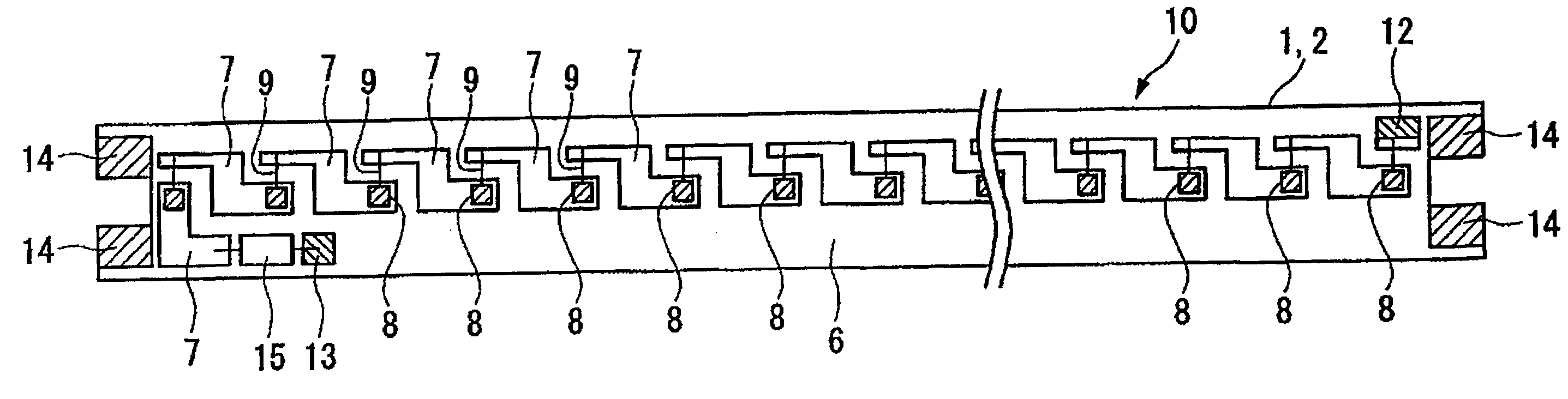
此外,图3及图4是表示本发明的发光模块的一实施方式的图,图3是在图1所示的发光元件安装用基板1上安装多个发光元件8而构成的发光模块10的俯视图,图4是该发光模块10的剖视图。3 and 4 are diagrams showing an embodiment of the light emitting module of the present invention, and FIG. 3 is a
本实施方式的发光元件安装用基板1,是在内核金属3的表面覆盖了第一珐琅层4的珐琅基板2的外侧,依次层叠第一导电层5和第二珐琅层6以及第二导电层7而形成的,设置在第一珐琅层4上的第一导电层5,如图2所示,沿珐琅基板2的长度方向平行地设置有2条,每条第一导电层5从珐琅基板2的一端连通到另一端,为沿着该第一导电层5的长度方向安装的多个发光元件8供电,并且,该第一导电层5延伸设置到设置在珐琅基板2的两端的突出部的表面,而构成成为与其它基板的连接部的连接用端子14。另外,虽然中间部进行了省略,但是,在本实施方式中,采用了串联连接30个发光元件8的构造。The light-emitting element mounting substrate 1 of the present embodiment is formed by laminating the first
在本实施方式的发光元件安装用基板1中,作为内核金属3的材料,只要是可在其表面牢固地形成珐琅层的金属即可,不特别限定,例如,可以使用钢板等。另外,第一珐琅层4和第二珐琅层6是烧接玻璃粉而形成的。此外,第一导电层5和第二导电层7,最好是,例如,通过以下方法等来形成:利用丝网印刷法等方法,沿着规定的图案印刷导电性银糊并进行烧接。In the light-emitting element mounting substrate 1 of the present embodiment, the material of the core metal 3 is not particularly limited as long as it can firmly form an enamel layer on the surface, and for example, a steel plate or the like can be used. In addition, the first enamel layer 4 and the
在本实施方式的发光元件安装用基板1中,如图4所示,在珐琅基板2上,沿珐琅基板2的长度方向设置有成为发光元件安装位置的槽11(凹部)。该槽11设置于两个第一导电层5之间,并且具有成为发光元件安装位置的底面和锥状的壁面。In the light emitting element mounting substrate 1 of this embodiment, as shown in FIG. The
在本实施方式的发光元件安装用基板1中,最外层的第二导电层7,大致呈Z字形,并且沿着珐琅基板2的长度方向相邻地配置有多个。第二导电层7的一部分,延伸设置到上述槽11的底面,并形成发光元件安装位置。形成于槽11内的第二导电层7,直接设置于第一珐琅层4上,并且第二导电层7的槽11以外的部分,形成于在两列中的一列第一导电层5上形成的第二珐琅层6上。另外,设置于珐琅基板2的端部附近的第二导电层7呈L形,其一部分形成于在两列中的另一列第一导电层5上形成的第二珐琅层6上。In the light-emitting element mounting substrate 1 of the present embodiment, the outermost second
第二珐琅层6上设置有通到第一导电层5的多个孔,在这些孔中填充厚膜银糊并进行烧接或利用钎料填埋,可形成用于连接上下的导电层的导电层连接部12和13。The
在珐琅基板2的两端,分别突出地形成有正-负电极用的两个连接用端子14。第一导电层5延伸设置到这些连接用端子14的表面和背面中的一个面或两个面上。第一导电层5的两端,与向基板供电以及用于和其它基板进行连接的连接用端子14进行电连接。At both ends of the
另外,在本实施方式中,设置有一列串联电路用的导电层,不过,根据安装发光元件8的数量,也可以在基板内部形成多个串联电路。例如,可以采用以下构造:串联连接30个发光元件的串联电路设置了2列或2列以上。In addition, in the present embodiment, one row of conductive layers for series circuits is provided, but a plurality of series circuits may be formed inside the substrate depending on the number of mounted
本实施方式的发光元件安装用基板1,因为采用了上述构造,所以,散热性好,不用另外迂回设置布线,使用基板内的导电层5、7就能安装多个发光元件8,并且,可以简单地进行和其它基板的连接,扩展性优良。The light-emitting element mounting substrate 1 of the present embodiment adopts the above-mentioned structure, so the heat dissipation is good, and a plurality of light-emitting
接下来,参考图3和图4对本发明的发光模块的一实施方式进行说明。本实施方式的发光模块10,是在图1所示的发光元件安装用基板1上安装多个发光元件8而构成的。每个发光元件8,安装于延伸设置到发光元件安装用基板1的槽11内的第二导电层7上,即安装于发光元件安装位置上。Next, an embodiment of the light emitting module of the present invention will be described with reference to FIGS. 3 and 4 . The
在本实施方式的发光模块10中,作为发光元件8最好为LED。并且,当将发光模块10应用于照明装置时,作为发光元件8最好是白色LED。作为该白色LED,最好是组合由氮化镓(GaN)类半导体制作的蓝色LED、和由蓝色光激发而发出黄色等一种或两种以上的蓝色以外的可见光的荧光体而成的白色LED等。并且,最好是,使上述荧光体混合并分散在用来封装安装在基板上的发光元件8的透明树脂中来使用。In the
在本实施方式的发光模块10中,通过将每个发光元件8安装在延伸设置到槽11的底面上的第二导电层7上,发光元件8的一个电极端子电连接于第二导电层7,此外,发光元件8的另一个电极端子,利用细金线等键合引线9而电连接于相邻的第二导电层7的端部。在安装于珐琅基板2的长度方向两端的发光元件8中,一端侧的发光元件8,通过键合引线9与一个导电层连接部12连接。此外,另一端侧的发光元件8安装于呈L形的第二导电层7上,该第二导电层7通过电流调整及元件保护用的调整电路15,连接于另一个导电层连接部13。由此,安装于发光元件安装用基板1上的多个发光元件8,串联连接为一列,如图2所示,通过在成为负电极的连接用端子14和成为正电极的另一个连接用端子14之间施加电压,向安装在该基板上的所有的发光元件8供电而使之发光。In the
接下来,对上述发光元件安装用基板1及使用了该基板的发光模块10的制造方法进行说明。Next, a method of manufacturing the above-described substrate 1 for mounting a light-emitting element and a light-emitting
首先,准备用于制作内核金属的金属板,将其切割成长板状,并且实施机械加工,形成成为发光元件安装位置的槽11,并且,为了形成连接用端子14而将其两端加工成コ字形,从而制作出内核金属3。First, prepare a metal plate for making the core metal, cut it into a long plate shape, and perform machining to form a
然后,将上述内核金属3浸渍到在适当的溶剂中分散了玻璃粉而得到的液体中,并在附近配置相对电极,在内核金属3与该相对电极之间施加电压,使玻璃粉电沉积在内核金属3的表面上。在进行了电沉积后,从液体中提出内核金属3进行干燥,并放入加热炉中,在规定温度范围内进行加热,将玻璃粉烧接在内核金属3的表面上,形成第一珐琅层4,从而制作出珐琅基板2。Then, the above-mentioned core metal 3 is immersed in a liquid obtained by dispersing glass powder in a suitable solvent, and an opposite electrode is arranged nearby, and a voltage is applied between the core metal 3 and the opposite electrode, so that the glass powder is electrodeposited. core metal 3 on the surface. After electrodeposition, the core metal 3 is taken out from the liquid to be dried, put into a heating furnace, and heated within a specified temperature range, and the glass powder is sintered on the surface of the core metal 3 to form the first enamel layer 4, thereby making the
然后,利用丝网印刷等方法,沿图2所示的第一导电层形成图案,在珐琅基板2的一个面上印刷厚膜银糊,之后进行烧接,形成和第一导电层5连接用的端子14。Then, use methods such as screen printing to form a pattern along the first conductive layer shown in FIG.
然后,与形成上述第一珐琅层4时同样地,将上述基板浸渍到分散了玻璃粉的液体中,在第一导电层5和相对电极之间施加电压,使玻璃粉电沉积在第一导电层5的表面。此时,为了不使玻璃粉电沉积到成为导电层连接部12、13的部分,而对其进行遮盖,或在电沉积之后除去玻璃粉。在将该基板干燥后,加热到规定温度来烧接玻璃,从而形成第二珐琅层6。Then, in the same manner as when forming the above-mentioned first enamel layer 4, the above-mentioned substrate is immersed in the liquid in which the glass powder is dispersed, and a voltage is applied between the first
然后,利用丝网印刷等方法,沿图1所示的第二导电层形成图案,印刷厚膜银糊,之后,进行烧接,从而形成第二导电层7和导电层连接部12、13。通过进行以上的各工序,可以得到图1所示的发光元件安装用基板1。Then, use screen printing or other methods to form a pattern along the second conductive layer shown in FIG. 1 , print thick-film silver paste, and then burn it to form the second
在如上述那样制作的发光元件安装用基板1的规定位置上,通过贴片(diebonding)安装发光元件8,进而形成调整电路15,并通过引线键合(wirebonding)使每个发光元件与第二导电层7进行电连接,由此,可得到图3所示的发光模块10。On the predetermined position of the light-emitting element mounting substrate 1 produced as above, the light-emitting
之后根据需要,向槽11内填充保护用的树脂或混合分散了荧光体的树脂,并使之固化,而封装发光元件8。Thereafter, if necessary, the
在本实施方式的发光模块10中,发光元件8因为安装于直接延伸设置到槽11内的第一珐琅层4上的第二导电层7上,所以,从发光元件8发出的热量易于传导到内核金属3,从而散热性良好。另外,因为未在珐琅基板2的背面形成导电层及追加的珐琅层,所以,也不会影响从珐琅基板2的背面侧进行的利用热传导的散热,并且,因为珐琅基板2的背面不产生电位,所以,固定于金属等的筐体也是安全的。In the light-emitting
当实际使用该发光模块10时,希望安装于长尺寸的金属板筐体或构造物上。例如,在两个端部安装接合器,以保持在筐体上,并在接合器内实现和彼此相邻的基板的电连接。这样,即使将10个到几十个发光模块并列连接为一列,只要利用单个电源对第一端的模块提供电源,就可以向所有的模块供电。此外,通过使第一导电层5确保充分的宽度,也能向离电源远的模块充分供电,并且,不会随着远离电源而变暗。When this light-emitting
另外,本发明不仅限于上述的实施方式,可以进行各种变更及修改。例如,也可以构成为:将发光元件并列4列,并将第一导电层5设置于没有发光元件列的部分的下层。第一导电层5也可以设置为两列以上的任何列数。此外,利用二维排列,还可以将单体模块大光量化。In addition, this invention is not limited to the above-mentioned embodiment, Various changes and modifications are possible. For example, a configuration may be adopted in which four light emitting elements are arranged in parallel, and the first
另外,也可以将第一导电层5仅用于一个极,而使另一个极与内核金属3电连接,将内核金属本身作为输送线、向基板内供电用的布线来利用。由此,可以得到更大的输送线的截面面积。In addition, the first
该发光模块10使用上述发光元件安装用基板1,并使用基板内的导电体来安装多个发光元件8,而不需另外迂回配置布线,所以能够小型化,此外能够廉价地提供发光模块。并且,能够通过连接用端子14容易地实现与未图示的其它的发光模块10的连接,所以,能够纵横无间隙地连结多个,从而能简单地实现大面积的照明装置。另外,可以在基本不降低电压的状态下将从一端供给的功率依次输送给相邻的发光模块,由此可以容易地向多个发光模块10供电。This light-emitting
(实施例)(Example)
将厚度为2mm的钢板切割成长板状,并实施机械加工,形成作为发光元件安装位置的槽,并且,为了形成连接用端子而将两端加工成コ字形,从而制作出内核金属。A steel plate with a thickness of 2 mm is cut into a long plate shape and machined to form a groove for mounting a light-emitting element, and both ends are processed into a U-shape to form a connection terminal to produce a core metal.
然后,在上述内核金属的表面上电沉积玻璃,之后进行烧结,利用厚度为100μm左右的第一珐琅层覆盖内核金属的表面,从而制作出珐琅基板。Then, glass is electrodeposited on the surface of the core metal, followed by sintering, and the surface of the core metal is covered with a first enamel layer with a thickness of about 100 μm, thereby producing an enamel substrate.
然后,在珐琅基板的一个面上,通过丝网印刷,按照图2所示的第一导电层形成图案印刷厚膜银糊,之后进行烧接,形成30μm左右的第一导电层。Then, on one surface of the enamel substrate, a thick-film silver paste was printed by screen printing according to the first conductive layer formation pattern shown in FIG. 2 , and then fired to form a first conductive layer of about 30 μm.
然后,对第一导电层施加电压而电沉积玻璃,之后进行烧结,由此在第一导电层的表面上形成厚100μm左右的第二珐琅层。Then, a voltage is applied to the first conductive layer to electrodeposit glass, and then fired to form a second enamel layer with a thickness of about 100 μm on the surface of the first conductive layer.
然后,按照图1的第二导电层形成图案,通过丝网印刷印刷厚膜银糊,之后进行烧接,形成厚30μm左右的第二导电层。Then, according to the patterning of the second conductive layer in FIG. 1 , thick-film silver paste was printed by screen printing, and then fired to form a second conductive layer with a thickness of about 30 μm.
如此制作的发光元件安装用基板,全长300mm、宽20mm、厚度约为1.5mm、槽底部的宽度为1.0mm、槽侧壁部倾斜角度为45度、连接用端子长度为7mm、连接用端子宽度为7mm、第一导电体的宽度为5mm、第二导电体形成个数为30个。The substrate for mounting the light-emitting element produced in this way has a total length of 300 mm, a width of 20 mm, a thickness of about 1.5 mm, a width of the bottom of the groove of 1.0 mm, an inclination angle of the side wall of the groove of 45 degrees, a length of the terminal for connection of 7 mm, and a length of the terminal for connection. The width was 7 mm, the width of the first conductor was 5 mm, and the number of second conductors was 30.
通过贴片将30个中心波长460nm的蓝色LED安装在该发光元件安装用基板的规定位置,并利用使用了细金线的引线键合将蓝色LED和各导电层连接起来。然后,在基板的槽内,填充分散了由蓝色光激发而发出黄色光的荧光体的环氧树脂,并使之固化,而封装各发光元件,从而制作出发出白色光的照明装置用的发光模块。Thirty blue LEDs with a center wavelength of 460 nm were mounted at predetermined positions on the light-emitting element mounting substrate by chip mounting, and the blue LEDs were connected to each conductive layer by wire bonding using thin gold wires. Then, in the groove of the substrate, epoxy resin dispersed with phosphors that are excited by blue light to emit yellow light is filled and cured, and each light-emitting element is packaged, thereby producing a light-emitting diode for lighting devices that emit white light. module.
将同样制作的4个发光模块,利用各自的连接用端子进行连接而连结成直线状,并从一端的模块的连接用端子供给200mA的直流电流,使所有的发光模块点亮。其结果是,所有的发光模块以同等的亮度发出白色光,并且供电侧和相反侧的发光模块不会变暗。在点亮一小时后,消耗功率约为19W,基板表面的温度为30℃,因而具有充分的散热性。Four light-emitting modules produced in the same manner were connected in a straight line with respective connection terminals, and a direct current of 200 mA was supplied from the connection terminal of the module at one end to light up all the light-emitting modules. As a result, all light emitting modules emit white light with equal brightness, and the light emitting modules on the power supply side and the opposite side are not dimmed. After one hour of lighting, the power consumption is about 19W, and the temperature of the substrate surface is 30°C, so it has sufficient heat dissipation.
Claims (4)
Applications Claiming Priority (2)
| Application Number | Priority Date | Filing Date | Title |
|---|---|---|---|
| JP2005172202 | 2005-06-13 | ||
| JP172202/2005 | 2005-06-13 |
Publications (2)
| Publication Number | Publication Date |
|---|---|
| CN101194374A CN101194374A (en) | 2008-06-04 |
| CN100583472C true CN100583472C (en) | 2010-01-20 |
Family
ID=37532202
Family Applications (1)
| Application Number | Title | Priority Date | Filing Date |
|---|---|---|---|
| CN200680020310A Expired - Fee Related CN100583472C (en) | 2005-06-13 | 2006-06-09 | Substrate for mounting light-emitting element, light-emitting module, and lighting device |
Country Status (6)
| Country | Link |
|---|---|
| US (1) | US7982230B2 (en) |
| EP (1) | EP1892773A4 (en) |
| KR (1) | KR101017921B1 (en) |
| CN (1) | CN100583472C (en) |
| TW (1) | TWI300276B (en) |
| WO (1) | WO2006134839A1 (en) |
Cited By (1)
| Publication number | Priority date | Publication date | Assignee | Title |
|---|---|---|---|---|
| WO2012058837A1 (en) * | 2010-11-01 | 2012-05-10 | 深圳市华星光电技术有限公司 | Lighting source radiation construction and backlight module |
Families Citing this family (13)
| Publication number | Priority date | Publication date | Assignee | Title |
|---|---|---|---|---|
| CN101176216B (en) * | 2005-06-07 | 2010-05-19 | 株式会社藤仓 | Enamel substrate for mounting light-emitting element, light-emitting element module, lighting device, display device, and traffic signal |
| US7923745B2 (en) * | 2007-07-18 | 2011-04-12 | Harvatek Corporation | LED chip package structure with high-efficiency light-emitting effect and method of packaging the same |
| KR101209759B1 (en) | 2008-03-26 | 2012-12-06 | 가부시키가이샤 시마네 덴시 이마후쿠 세이사쿠쇼 | Semiconductor light emitting module and method for manufacturing the same |
| WO2011086761A1 (en) * | 2010-01-14 | 2011-07-21 | シャープ株式会社 | Led circuit board, backlight unit, and liquid crystal display apparatus |
| US20110062482A1 (en) * | 2010-01-20 | 2011-03-17 | Bridgelux, Inc. | Apparatus And Method For Enhancing Connectability In LED Array Using Metal Traces |
| JP5537295B2 (en) * | 2010-07-05 | 2014-07-02 | パナソニック株式会社 | Light emitting element mounting wiring pattern, light emitting element mounting wiring board having light emitting element mounting wiring pattern, light emitting module using light emitting element mounting wiring board, and lighting fixture equipped with light emitting module |
| JP2012049367A (en) * | 2010-08-27 | 2012-03-08 | Kyocera Elco Corp | Semiconductor light-emitting device attachment module, semiconductor light-emitting device module, semiconductor light-emitting device lighting apparatus, and manufacturing method of semiconductor light-emitting device attachment module |
| JPWO2012144126A1 (en) | 2011-04-20 | 2014-07-28 | パナソニック株式会社 | Light source, backlight unit, liquid crystal display device and illumination device |
| DE102011110799A1 (en) * | 2011-08-22 | 2013-02-28 | Heraeus Materials Technology Gmbh & Co. Kg | Substrate for the construction of electronic elements |
| KR101282725B1 (en) * | 2011-11-10 | 2013-07-05 | 교우세라 커넥터 프로덕츠 가부시키가이샤 | Module for Mounting LED And LED Module |
| CN103430339B (en) * | 2012-03-13 | 2014-09-10 | 松下电器产业株式会社 | Substrate, light-emitting device, and illumination device |
| KR101402650B1 (en) * | 2012-06-18 | 2014-06-03 | 교우세라 커넥터 프로덕츠 가부시키가이샤 | Module for mounting LED module and LED module having the same |
| KR102203683B1 (en) * | 2014-04-10 | 2021-01-15 | 엘지이노텍 주식회사 | Printed circuit board and luminous device including the same |
Citations (2)
| Publication number | Priority date | Publication date | Assignee | Title |
|---|---|---|---|---|
| JPH06284942A (en) | 1993-04-07 | 1994-10-11 | Nissan Motor Co Ltd | Control device for vehicle seat |
| US20030193055A1 (en) * | 2002-04-10 | 2003-10-16 | Martter Robert H. | Lighting device and method |
Family Cites Families (34)
| Publication number | Priority date | Publication date | Assignee | Title |
|---|---|---|---|---|
| US4256796A (en) | 1979-11-05 | 1981-03-17 | Rca Corporation | Partially devitrified porcelain composition and articles prepared with same |
| JPS599982A (en) | 1982-07-08 | 1984-01-19 | Sumitomo Electric Ind Ltd | Continuously assembled light emitting diode |
| JPS6284942U (en) * | 1985-11-19 | 1987-05-30 | ||
| JPS6428886A (en) | 1987-07-23 | 1989-01-31 | Matsushita Electric Industrial Co Ltd | Hybrid integrated circuit board |
| US4935665A (en) * | 1987-12-24 | 1990-06-19 | Mitsubishi Cable Industries Ltd. | Light emitting diode lamp |
| JP2650236B2 (en) * | 1990-01-11 | 1997-09-03 | ローム 株式会社 | Manufacturing method of LED array light source |
| JPH03258158A (en) * | 1990-03-08 | 1991-11-18 | Canon Inc | Original reader |
| JPH0488694A (en) | 1990-07-31 | 1992-03-23 | Matsushita Electric Ind Co Ltd | Enameled foil substrate, electronic component provided therewith, and manufacture thereof |
| US5150016A (en) * | 1990-09-21 | 1992-09-22 | Rohm Co., Ltd. | LED light source with easily adjustable luminous energy |
| JP2890809B2 (en) | 1990-11-07 | 1999-05-17 | 日本電気株式会社 | Thick film printed circuit board |
| JPH05299701A (en) * | 1992-04-17 | 1993-11-12 | Sharp Corp | Line illumination unit |
| JP3296623B2 (en) | 1993-05-11 | 2002-07-02 | 三洋電機株式会社 | Optical print head |
| JPH07281619A (en) | 1994-04-04 | 1995-10-27 | Rohm Co Ltd | LED lamp and its mounting structure on the board |
| JPH1098215A (en) * | 1996-09-24 | 1998-04-14 | Toyoda Gosei Co Ltd | Light emitting diode device |
| US6517218B2 (en) | 2000-03-31 | 2003-02-11 | Relume Corporation | LED integrated heat sink |
| JP2002009349A (en) | 2000-06-26 | 2002-01-11 | Koha Co Ltd | LED surface light emitting device and method of manufacturing the same |
| US6617520B1 (en) | 2000-08-30 | 2003-09-09 | Heatron, Inc. | Circuit board |
| JP4737575B2 (en) | 2001-01-30 | 2011-08-03 | ハリソン東芝ライティング株式会社 | Light emitting diode array and light source device |
| DE60137972D1 (en) | 2001-04-12 | 2009-04-23 | Matsushita Electric Works Ltd | LIGHT SOURCE ELEMENT WITH LED AND METHOD FOR THE PRODUCTION THEREOF |
| WO2003016782A1 (en) | 2001-08-09 | 2003-02-27 | Matsushita Electric Industrial Co., Ltd. | Led illuminator and card type led illuminating light source |
| JP2003324214A (en) | 2002-04-30 | 2003-11-14 | Omron Corp | Light emitting module |
| US20030219919A1 (en) | 2002-05-23 | 2003-11-27 | Wang Der-Nan | Package method for enhancing the brightness of LED |
| JP4061479B2 (en) | 2002-07-16 | 2008-03-19 | 三菱電機照明株式会社 | LED light source device |
| JP2004055229A (en) | 2002-07-17 | 2004-02-19 | Mitsubishi Electric Lighting Corp | Led lighting system and lighting equipment |
| JP2004079750A (en) | 2002-08-16 | 2004-03-11 | Fuji Photo Film Co Ltd | Light emitting device |
| JP4187239B2 (en) | 2002-10-22 | 2008-11-26 | シチズン電子株式会社 | High brightness light emitting device and manufacturing method thereof |
| US6982518B2 (en) * | 2003-10-01 | 2006-01-03 | Enertron, Inc. | Methods and apparatus for an LED light |
| TWI232565B (en) | 2003-11-28 | 2005-05-11 | Topson Opto Semiconductor Corp | Semiconductor chip-carrying substrate and its manufacturing method |
| TWI224876B (en) | 2003-12-23 | 2004-12-01 | Uni Light Technology Inc | Method for forming an LED device with a metallic substrate |
| US6966674B2 (en) | 2004-02-17 | 2005-11-22 | Au Optronics Corp. | Backlight module and heat dissipation structure thereof |
| US6884646B1 (en) | 2004-03-10 | 2005-04-26 | Uni Light Technology Inc. | Method for forming an LED device with a metallic substrate |
| US20050199899A1 (en) | 2004-03-11 | 2005-09-15 | Ming-Der Lin | Package array and package unit of flip chip LED |
| US7241030B2 (en) | 2004-07-30 | 2007-07-10 | Avago Technologies Ecbu Ip (Singapore) Pte. Ltd. | Illumination apparatus and method |
| KR101017917B1 (en) * | 2005-06-07 | 2011-03-04 | 가부시키가이샤후지쿠라 | Board for mounting light emitting device, light emitting device module, lighting device, display device and traffic signal |
-
2006
- 2006-06-09 CN CN200680020310A patent/CN100583472C/en not_active Expired - Fee Related
- 2006-06-09 WO PCT/JP2006/311614 patent/WO2006134839A1/en not_active Ceased
- 2006-06-09 TW TW095120581A patent/TWI300276B/en not_active IP Right Cessation
- 2006-06-09 EP EP06766526.5A patent/EP1892773A4/en not_active Withdrawn
- 2006-06-09 KR KR1020077029208A patent/KR101017921B1/en not_active Expired - Fee Related
-
2007
- 2007-12-10 US US11/953,522 patent/US7982230B2/en not_active Expired - Fee Related
Patent Citations (2)
| Publication number | Priority date | Publication date | Assignee | Title |
|---|---|---|---|---|
| JPH06284942A (en) | 1993-04-07 | 1994-10-11 | Nissan Motor Co Ltd | Control device for vehicle seat |
| US20030193055A1 (en) * | 2002-04-10 | 2003-10-16 | Martter Robert H. | Lighting device and method |
Cited By (1)
| Publication number | Priority date | Publication date | Assignee | Title |
|---|---|---|---|---|
| WO2012058837A1 (en) * | 2010-11-01 | 2012-05-10 | 深圳市华星光电技术有限公司 | Lighting source radiation construction and backlight module |
Also Published As
| Publication number | Publication date |
|---|---|
| WO2006134839A1 (en) | 2006-12-21 |
| TWI300276B (en) | 2008-08-21 |
| EP1892773A4 (en) | 2014-07-30 |
| KR101017921B1 (en) | 2011-03-08 |
| US20080258169A1 (en) | 2008-10-23 |
| CN101194374A (en) | 2008-06-04 |
| EP1892773A1 (en) | 2008-02-27 |
| US7982230B2 (en) | 2011-07-19 |
| KR20080012973A (en) | 2008-02-12 |
| TW200703727A (en) | 2007-01-16 |
Similar Documents
| Publication | Publication Date | Title |
|---|---|---|
| KR101017917B1 (en) | Board for mounting light emitting device, light emitting device module, lighting device, display device and traffic signal | |
| US7982230B2 (en) | Substrate for mounting light emitting element, light emitting module and lighting apparatus | |
| EP2182783A2 (en) | Light-emitting module and illuminating apparatus | |
| CN101176216B (en) | Enamel substrate for mounting light-emitting element, light-emitting element module, lighting device, display device, and traffic signal | |
| US9577153B2 (en) | Light emission device and illumination device | |
| KR20100117451A (en) | Pcb with radiation hole and led illumination device using it | |
| EP2478750B1 (en) | Light-source module and light-emitting device | |
| CN101997079B (en) | Light-emitting device | |
| CN101189737A (en) | Light-emitting element mounting substrate and light-emitting element module | |
| JP3884057B2 (en) | Light-emitting element mounting substrate, light-emitting module, and lighting device | |
| JP6104946B2 (en) | Light emitting device and manufacturing method thereof | |
| KR102079938B1 (en) | Ceramic substrate for led and method of manufacturing the same | |
| CN101266851A (en) | Electrostatic countermeasure component and electronic component module using the same | |
| JP2009038202A (en) | Light-emitting element mounting substrate, light-emitting element module, lighting device, display device, and traffic signal device | |
| JP2007013027A (en) | Light-emitting element mounting enamel substrate, light-emitting element module, lighting device, display device, and traffic signal device | |
| JP6411320B2 (en) | Light emitting device and lighting device | |
| US8888324B2 (en) | Light-emitting device, method for assembling same and luminaire | |
| JP2020150097A (en) | Light emitting device, light emitting module and its manufacturing method | |
| EP2806211A1 (en) | Solid-state lighting device and related process | |
| JP4087419B2 (en) | Light emitting device mounting enamel substrate, light emitting device module, lighting device, display device, and traffic signal device | |
| CN103715189A (en) | Lighting device and illuminating device | |
| JP2008091952A (en) | Method for manufacturing light-emitting element mounting enamel substrate and method for manufacturing light-emitting element module | |
| JP2014146469A (en) | Illumination apparatus |
Legal Events
| Date | Code | Title | Description |
|---|---|---|---|
| C06 | Publication | ||
| PB01 | Publication | ||
| C10 | Entry into substantive examination | ||
| SE01 | Entry into force of request for substantive examination | ||
| C14 | Grant of patent or utility model | ||
| GR01 | Patent grant | ||
| C17 | Cessation of patent right | ||
| CF01 | Termination of patent right due to non-payment of annual fee |
Granted publication date: 20100120 Termination date: 20130609 |