CN100464160C - An Absolute Composite Shaft Photoelectric Shaft Angle Encoder - Google Patents
An Absolute Composite Shaft Photoelectric Shaft Angle Encoder Download PDFInfo
- Publication number
- CN100464160C CN100464160C CNB2006100165160A CN200610016516A CN100464160C CN 100464160 C CN100464160 C CN 100464160C CN B2006100165160 A CNB2006100165160 A CN B2006100165160A CN 200610016516 A CN200610016516 A CN 200610016516A CN 100464160 C CN100464160 C CN 100464160C
- Authority
- CN
- China
- Prior art keywords
- shaft
- flange
- encoder
- axle sleeve
- main
- Prior art date
- Legal status (The legal status is an assumption and is not a legal conclusion. Google has not performed a legal analysis and makes no representation as to the accuracy of the status listed.)
- Expired - Fee Related
Links
- 239000002131 composite material Substances 0.000 title claims abstract description 8
- 230000015572 biosynthetic process Effects 0.000 claims 1
- 230000003287 optical effect Effects 0.000 claims 1
- 238000005259 measurement Methods 0.000 abstract description 6
- 150000001875 compounds Chemical class 0.000 abstract description 4
- 239000000463 material Substances 0.000 description 4
- 238000006073 displacement reaction Methods 0.000 description 3
- 238000010586 diagram Methods 0.000 description 2
- 229910000831 Steel Inorganic materials 0.000 description 1
- 230000007547 defect Effects 0.000 description 1
- 238000002474 experimental method Methods 0.000 description 1
- 238000011900 installation process Methods 0.000 description 1
- 238000004519 manufacturing process Methods 0.000 description 1
- 238000000034 method Methods 0.000 description 1
- 239000005304 optical glass Substances 0.000 description 1
- 239000002952 polymeric resin Substances 0.000 description 1
- 230000008092 positive effect Effects 0.000 description 1
- 239000010959 steel Substances 0.000 description 1
- 239000000758 substrate Substances 0.000 description 1
- 229920003002 synthetic resin Polymers 0.000 description 1
Images


Landscapes
- Optical Transform (AREA)
Abstract
一种绝对示复合型轴系光电轴角编码器属于光电测量技术领域中涉及的一种编码器。本发明要解决的技术问题:提供一种绝对式复合型轴系光电轴角编码器。解决技术问题的技术方案包括法兰盘、壳体、复合轴系、读数头。主轴位于编码器的对称中心位置,轴套套装在主轴上,两者之间通过轴承转动接触。在轴套的外侧套装法兰空心轴,法兰空心轴与法兰盘同心固连,在轴套的下端和法兰空心轴之间的空隙上装有锁紧螺母,可锁紧轴套和法兰空心轴的位置。壳体将读数头和复合型轴系罩上,下端用螺钉与法兰盘固连。这种复合型轴系的编码器在和主体仪器安装时,可实现编码器本身的“0”位与主体仪器自身的“0”位一次性重合定位。
The utility model relates to an absolute indication composite shaft system photoelectric shaft angle encoder, which belongs to an encoder related to the technical field of photoelectric measurement. The technical problem to be solved by the present invention is to provide an absolute compound shafting photoelectric shaft angle encoder. The technical solutions for solving technical problems include flanges, casings, composite shafting, and reading heads. The main shaft is located at the symmetrical center of the encoder, the shaft sleeve is set on the main shaft, and the two are in rotational contact through bearings. The flange hollow shaft is installed on the outside of the shaft sleeve, and the flange hollow shaft is concentrically connected with the flange plate. A lock nut is installed on the gap between the lower end of the shaft sleeve and the flange hollow shaft to lock the shaft sleeve and the flange. The position of the blue hollow shaft. The casing covers the reading head and the composite shafting cover, and the lower end is fixedly connected with the flange with screws. When the encoder of this compound shaft system is installed with the main instrument, the "0" position of the encoder itself and the "0" position of the main instrument itself can be coincidently positioned at one time.
Description
一.技术领域 1. Technical field
本发明属于光电测量技术领域中涉及的一种编码器。The invention belongs to an encoder related to the technical field of photoelectric measurement.
二.背景技术 2. Background technology
光电轴角编码器是一种具有代表性的角度测量传感器,已被广泛的应用于工业、航空航天技术、科学试验等技术领域。通常光电轴角编码器多为单一轴系,加工制造的工艺也比较成熟。与本发明最为接近的已有技术是中国科学院长春光学精密机械与物理研究所开发的产品。如图1所示,包括法兰盘1、壳体2、轴系及读数头。其中轴系中主要包括主轴3、轴承4、轴套5;读数头中主要包括码盘6、基板7、狭缝8、发光元件9、接收元件10。The photoelectric shaft encoder is a representative angle measurement sensor, which has been widely used in technical fields such as industry, aerospace technology, and scientific experiments. Usually, the photoelectric shaft encoder is mostly a single shaft system, and the processing and manufacturing technology is relatively mature. The closest prior art with the present invention is the product developed by Changchun Institute of Optics, Fine Mechanics and Physics, Chinese Academy of Sciences. As shown in Figure 1, it includes a
主轴3位于编码器的对称中心位置,它的一端伸出法兰盘1的中心孔,主轴3和轴套5之间通过轴承4转动接触,码盘6套装在主轴3的台肩上,用螺钉固连,随主轴3转动,轴套5与法兰盘1之间用螺钉固连;读数头中的发光元件9安装在和轴套5相连接的支架上,位于码盘6的下面,基板7通过螺钉固定在轴套5上,位于码盘6的上面,在基板7的带孔处安装接收元件10,使发光元件9和接收元件10位于读数头的通光光路上。在主轴3带动码盘6转动时与狭缝8之间产生相对运动。当光通过码盘码道和狭缝时,读数头读取的数据记录着被测物体的角位移数据。The
该光电轴角编码器在和主体仪器连接时调“0”非常困难。It is very difficult to adjust "0" when the photoelectric shaft encoder is connected with the main instrument.
任何一种测量都有一定的基点,即“0”点。仪器本身的“0”点与空间坐标的“0”点不重合,两者的差量称为“0”位差。在测量过程中“0”位差应限定在一定的范围内,编码器往主体仪器安装时应使编码器本身“0”位与主体仪器自身“0”位重合,为达到这一目的需要反复拆装固定编码器,费时费力,很困难。Any kind of measurement has a certain base point, that is, "0" point. The "0" point of the instrument itself does not coincide with the "0" point of the space coordinates, and the difference between the two is called "0" position difference. During the measurement process, the "0" position difference should be limited within a certain range. When the encoder is installed on the main instrument, the "0" position of the encoder itself should coincide with the "0" position of the main instrument itself. It is time-consuming and labor-intensive to disassemble and assemble the fixed encoder, which is very difficult.
三、发明内容 3. Contents of the invention
为了克服已有技术存在的缺陷,本发明的目的在于使编码器往主体仪器上安装一次到位,无须二次拆装固定,发现二者“0”位不重合,只需微动微调轴系即可调“0”,特设计一种复合轴系编码器。In order to overcome the defects existing in the prior art, the purpose of the present invention is to install the encoder on the main instrument in place once, without the need for secondary disassembly and fixation. Adjustable "0", specially designed a compound shaft encoder.
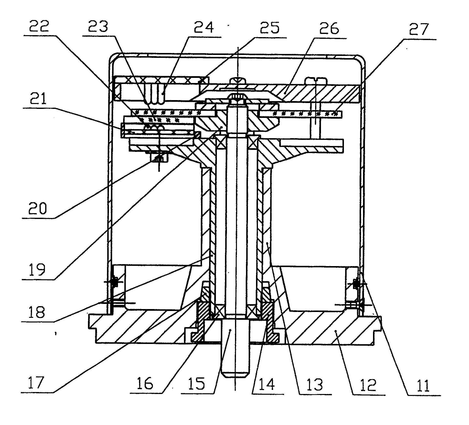
本发明要解决的技术问题是:提供一种绝对式复合轴系光电轴角编码器。解决技术问题的技术方案如图2所示:包括壳体11、法兰盘12、轴系、读数头。其中轴系中包括法兰空心轴13、锁紧螺母14、主轴15、轴承16、弹性环17、轴套18;读数头中包括码盘座19、支撑架20、接收线路板21、接收管22、狭缝盘23、发光管24、发光线路板25、基板26、码盘27。The technical problem to be solved by the present invention is to provide an absolute composite shafting photoelectric shaft angle encoder. The technical solution to solve the technical problem is shown in Figure 2: it includes a
在轴系中主轴15位于编码器的对称中心位置,在主轴15的上端装有码盘座19,两者之间通过螺纹配合固连,在码盘座19的下面,轴套18套装在主轴15上,它与主轴15之间通过轴承16转动接触,构成主轴系统;在轴套18的外侧套装法兰空心轴13,法兰空心轴13的下端与法兰盘12同心固连,实际上它们是一体件,轴套18与法兰空心轴13之间是转动接触,在轴套18的下端和法兰空心轴13的下端喇叭口之间的空隙处,轴套18上套装有弹性环17,在弹性环17的下面装有锁紧螺母14,锁紧螺母14和轴套18下端的外径之间是螺纹配合,可锁紧轴套18和法兰空心轴13。轴套18和法兰盘12、法兰空心轴13、锁紧螺母14构成了微调轴系;主轴系和微调轴系的结合形成了复合轴系;微调轴系的法兰盘12上带有“0”标记,该标记与主体仪器自身的“0”位标记应重合。In the shaft system, the
在读数头中码盘27装在码盘座19上,两者固连,码盘27随主轴15转动,在主轴15的上端装有基板26,基板26的工作面与主轴15垂直,它通过螺钉固连在轴套18上,在基板26的带孔处装有发光管24和发光线路板25,在轴套18上端的伸出部位装有支撑架20,支撑架20的上端面装有狭缝盘23,狭缝盘23和位于它上面的码盘27两者平行,且保持一定的间隙,支撑架20的下端面装有接收线路板21和接收管22,使发光管24和接收管22位于读数头的通光光路上,在主轴15带动码盘27转动时,狭缝盘23相对不动,两者之间产生相对位移,当有光通过码盘码道和狭缝时,读数头有信号输出,记录着角位移数据;壳体11将轴系和读数头罩上,下端落在法兰盘12的台肩上,用螺钉与法兰盘12固连。In the reading head, the
本发明的积极效果:轴系中的微调轴系能调整锁定编码器的“0”位与主体仪器的“0”位重合。解决了已有技术中编码器往主体仪器安装过程中,反复拆装调整“0”位的问题,省时省力,大大提高了工作效率。The positive effect of the present invention: the fine-tuning shaft system in the shaft system can adjust the "0" position of the locking encoder to coincide with the "0" position of the main instrument. It solves the problem of repeated disassembly and assembly and adjustment of the "0" position during the installation process of the encoder to the main instrument in the prior art, saves time and effort, and greatly improves work efficiency.
四、附图说明 4. Description of drawings
图1是已有技术绝对式单一轴系光电轴角编码器的结构示意图;Fig. 1 is the structural representation of prior art absolute type single-shaft photoelectric shaft-angle encoder;
图2是本发明的绝对式复合轴系光电轴角编码器的结构示意图;Fig. 2 is the structural representation of the absolute compound shaft system photoelectric shaft angle encoder of the present invention;
图3是本发明编码器中发光线路板25的电路原理图;Fig. 3 is the schematic circuit diagram of the light-
图4是本发明编码器中接收线路板21的电路原理图。Fig. 4 is a schematic circuit diagram of the
五、具体实施方式 5. Specific implementation
本发明按图2所示的结构实施。其中法兰盘12、法兰空心轴13、锁紧螺母14、主轴15、轴套18、码盘座19、支撑架20等件的材质采用轴承钢Gr15;法兰盘12和法兰空心轴13做成一体件;壳体11的材质采用2A12;轴承16采用C级或D级标准深沟球轴承;弹性环17的材质采用65Mn;接收管22采用三极管,发光管24采用红外二极管,它们均采用Honeywell产品;狭缝盘23和码盘27的材质采用K9光学玻璃或高分子树脂材料,狭缝盘23上的狭缝分布和码盘27上的码道布局以及轴系中各零件的公差配合均由测角精度要求来设定。The present invention is implemented by the structure shown in FIG. 2 . The
Claims (1)
Priority Applications (1)
| Application Number | Priority Date | Filing Date | Title |
|---|---|---|---|
| CNB2006100165160A CN100464160C (en) | 2006-01-12 | 2006-01-12 | An Absolute Composite Shaft Photoelectric Shaft Angle Encoder |
Applications Claiming Priority (1)
| Application Number | Priority Date | Filing Date | Title |
|---|---|---|---|
| CNB2006100165160A CN100464160C (en) | 2006-01-12 | 2006-01-12 | An Absolute Composite Shaft Photoelectric Shaft Angle Encoder |
Publications (2)
| Publication Number | Publication Date |
|---|---|
| CN101000250A CN101000250A (en) | 2007-07-18 |
| CN100464160C true CN100464160C (en) | 2009-02-25 |
Family
ID=38692309
Family Applications (1)
| Application Number | Title | Priority Date | Filing Date |
|---|---|---|---|
| CNB2006100165160A Expired - Fee Related CN100464160C (en) | 2006-01-12 | 2006-01-12 | An Absolute Composite Shaft Photoelectric Shaft Angle Encoder |
Country Status (1)
| Country | Link |
|---|---|
| CN (1) | CN100464160C (en) |
Cited By (1)
| Publication number | Priority date | Publication date | Assignee | Title |
|---|---|---|---|---|
| CN102607617A (en) * | 2012-03-31 | 2012-07-25 | 中国科学院长春光学精密机械与物理研究所 | Multi-turn absolute type double-reading group combined photoelectric shaft angle encoder |
Families Citing this family (8)
| Publication number | Priority date | Publication date | Assignee | Title |
|---|---|---|---|---|
| CN101504294B (en) * | 2009-03-09 | 2010-09-29 | 中国科学院光电技术研究所 | Positioning device for photoelectric pair tube on code disc |
| CN102087120B (en) * | 2010-11-19 | 2012-07-11 | 无锡瑞茂光电科技有限公司 | Novel encoder structure |
| CN102506766A (en) * | 2011-10-25 | 2012-06-20 | 四川九洲电器集团有限责任公司 | High-precision photoelectric-angular encoder |
| CN102545912B (en) * | 2011-12-27 | 2015-12-16 | 温州奇玺电器科技有限公司 | Absolute value encoder |
| CN103644927B (en) * | 2013-12-12 | 2016-01-13 | 刘万更 | Adjustable resolution stepless photoelectric absolute value encoder |
| CN104501845B9 (en) * | 2015-01-09 | 2017-10-24 | 杭州谷立电气技术有限公司 | Novel encoder structure and method for positioning motor by using same |
| CN105258715A (en) * | 2015-10-22 | 2016-01-20 | 珠海格力节能环保制冷技术研究中心有限公司 | Photoelectric encoder |
| CN109001483A (en) * | 2018-06-01 | 2018-12-14 | 苏州古柏利电子科技有限公司 | A kind of speed probe |
Citations (4)
| Publication number | Priority date | Publication date | Assignee | Title |
|---|---|---|---|---|
| US3939712A (en) * | 1973-06-18 | 1976-02-24 | Albert Yakovlevich Jurovsky | Pneumatic differential pressure sensor |
| JPH09280886A (en) * | 1996-04-12 | 1997-10-31 | Fuji Electric Co Ltd | Digital arithmetic circuit of capacitance sensor |
| JPH09303306A (en) * | 1996-05-20 | 1997-11-25 | Yamatake Honeywell Co Ltd | Field device adjustment mechanism |
| CN1360198A (en) * | 2001-10-30 | 2002-07-24 | 中国科学院长春光学精密机械与物理研究所 | Combined multifunctional encoder |
-
2006
- 2006-01-12 CN CNB2006100165160A patent/CN100464160C/en not_active Expired - Fee Related
Patent Citations (4)
| Publication number | Priority date | Publication date | Assignee | Title |
|---|---|---|---|---|
| US3939712A (en) * | 1973-06-18 | 1976-02-24 | Albert Yakovlevich Jurovsky | Pneumatic differential pressure sensor |
| JPH09280886A (en) * | 1996-04-12 | 1997-10-31 | Fuji Electric Co Ltd | Digital arithmetic circuit of capacitance sensor |
| JPH09303306A (en) * | 1996-05-20 | 1997-11-25 | Yamatake Honeywell Co Ltd | Field device adjustment mechanism |
| CN1360198A (en) * | 2001-10-30 | 2002-07-24 | 中国科学院长春光学精密机械与物理研究所 | Combined multifunctional encoder |
Cited By (1)
| Publication number | Priority date | Publication date | Assignee | Title |
|---|---|---|---|---|
| CN102607617A (en) * | 2012-03-31 | 2012-07-25 | 中国科学院长春光学精密机械与物理研究所 | Multi-turn absolute type double-reading group combined photoelectric shaft angle encoder |
Also Published As
| Publication number | Publication date |
|---|---|
| CN101000250A (en) | 2007-07-18 |
Similar Documents
| Publication | Publication Date | Title |
|---|---|---|
| CN100464160C (en) | An Absolute Composite Shaft Photoelectric Shaft Angle Encoder | |
| CN207163481U (en) | A kind of triple axle fibre optical sensor device for installing and adjusting | |
| CN102607433B (en) | Multi-point detection device for thickness of bearing bush | |
| CN108801179A (en) | A kind of non-contact axis coaxality measuring mechanism and method at a distance | |
| CN103499365A (en) | Rotary transformer static and dynamic angle measuring accuracy calibration device and method | |
| CN103743924B (en) | A kind of blade rotational speed measurement mechanism | |
| CN100464161C (en) | An Absolute Double Shaft Photoelectric Shaft Angle Encoder | |
| CN104358979A (en) | Split type ultra-precision aerostatic uniaxial rotary table | |
| CN204613756U (en) | A Rotating Mirror Structure and System for Speed Feedback | |
| CN101769761A (en) | Device for testing radial magnetic field sensitivity of fiber optic gyro | |
| CN108917684A (en) | A kind of cross-section thin-wall bearing measuring device and measuring method | |
| CN109357111B (en) | A single-axis precision test turntable | |
| CN104653408A (en) | Device for detecting the deformation of a rotor blade of a wind power plant and corresponding rotor blade | |
| CN209181750U (en) | A Measuring Device for Robot Repeat Positioning Accuracy Based on Tie Rod Sensor | |
| CN209961237U (en) | An indexing photoelectric angle encoder | |
| CN105699090A (en) | Pneumatic parameter sensor | |
| CN209310825U (en) | Single-bearing photoelectric encoder | |
| CN2474991Y (en) | Photoelectric axial angle coder with intercalation structure | |
| CN206131944U (en) | Slant geometrical tolerances measuring apparatu | |
| CN205332940U (en) | Raceway measuring apparatu is synthesized to bearing | |
| CN207007405U (en) | It is a kind of to be easy to fixed pressure gauge | |
| CN222528578U (en) | Contour measuring rod mechanism | |
| CN109974984A (en) | A kind of ejection terminal electric switch mechanism detection device | |
| CN102950458A (en) | Three-dimensional positioning and assembly tool for mixed-flow runner blades | |
| CN2663924Y (en) | An absolute type optical electric axial angle encoder employing circular ring narrow slit rack and simplified shafting |
Legal Events
| Date | Code | Title | Description |
|---|---|---|---|
| C06 | Publication | ||
| PB01 | Publication | ||
| C10 | Entry into substantive examination | ||
| SE01 | Entry into force of request for substantive examination | ||
| C14 | Grant of patent or utility model | ||
| GR01 | Patent grant | ||
| C17 | Cessation of patent right | ||
| CF01 | Termination of patent right due to non-payment of annual fee |
Granted publication date: 20090225 Termination date: 20110112 |