CN100437097C - A Containerized Cargo/Vehicle Inspection System with Adjustable Radiation Ray Angle - Google Patents
A Containerized Cargo/Vehicle Inspection System with Adjustable Radiation Ray Angle Download PDFInfo
- Publication number
- CN100437097C CN100437097C CNB2003101001821A CN200310100182A CN100437097C CN 100437097 C CN100437097 C CN 100437097C CN B2003101001821 A CNB2003101001821 A CN B2003101001821A CN 200310100182 A CN200310100182 A CN 200310100182A CN 100437097 C CN100437097 C CN 100437097C
- Authority
- CN
- China
- Prior art keywords
- accelerator
- adjustment mechanism
- frame
- cantilever
- base
- Prior art date
- Legal status (The legal status is an assumption and is not a legal conclusion. Google has not performed a legal analysis and makes no representation as to the accuracy of the status listed.)
- Expired - Fee Related
Links
Images

Classifications
-
- G—PHYSICS
- G01—MEASURING; TESTING
- G01N—INVESTIGATING OR ANALYSING MATERIALS BY DETERMINING THEIR CHEMICAL OR PHYSICAL PROPERTIES
- G01N23/00—Investigating or analysing materials by the use of wave or particle radiation, e.g. X-rays or neutrons, not covered by groups G01N3/00 – G01N17/00, G01N21/00 or G01N22/00
- G01N23/02—Investigating or analysing materials by the use of wave or particle radiation, e.g. X-rays or neutrons, not covered by groups G01N3/00 – G01N17/00, G01N21/00 or G01N22/00 by transmitting the radiation through the material
-
- G—PHYSICS
- G01—MEASURING; TESTING
- G01V—GEOPHYSICS; GRAVITATIONAL MEASUREMENTS; DETECTING MASSES OR OBJECTS; TAGS
- G01V5/00—Prospecting or detecting by the use of ionising radiation, e.g. of natural or induced radioactivity
- G01V5/20—Detecting prohibited goods, e.g. weapons, explosives, hazardous substances, contraband or smuggled objects
Landscapes
- Physics & Mathematics (AREA)
- Life Sciences & Earth Sciences (AREA)
- General Physics & Mathematics (AREA)
- High Energy & Nuclear Physics (AREA)
- General Life Sciences & Earth Sciences (AREA)
- Geophysics (AREA)
- Health & Medical Sciences (AREA)
- Chemical & Material Sciences (AREA)
- Analytical Chemistry (AREA)
- Biochemistry (AREA)
- General Health & Medical Sciences (AREA)
- Immunology (AREA)
- Pathology (AREA)
- Analysing Materials By The Use Of Radiation (AREA)
- Automobile Manufacture Line, Endless Track Vehicle, Trailer (AREA)
Abstract
一种可调整辐射射线角度的集装货物/车辆检查系统,涉及辐射检测技术领域。本发明包括装有探测器的探测器臂架、准直器二、拖动装置和装有加速器的加速器架。加速器的射线正对依次放置的校正器和准直器一、准直器二。其结构特点是,所述加速器架是由可使底座作水平前后运动的水平调节机构、可使弯型框架作垂直上下运动的竖直调节机构、可使悬臂作旋转运动的回转调节机构、可使加速器俯仰运动的俯仰调节机构以及由底座、竖臂、弯型框架和悬臂形成的机架组成。同现有技术相比,本发明具有结构设计合理、使用便捷、成形图像质量高的特点,特别是对某些可疑区域进行重点扫描、可获得令人满意的效果,是海关系统检查货物的必备设备。
A containerized goods/vehicle inspection system capable of adjusting the angle of radiation rays relates to the technical field of radiation detection. The invention comprises a detector arm frame equipped with a detector, a collimator two, a drag device and an accelerator frame equipped with an accelerator. The rays of the accelerator face the corrector, the first collimator and the second collimator which are placed in sequence. Its structural feature is that the accelerator frame is composed of a horizontal adjustment mechanism that can make the base move back and forth horizontally, a vertical adjustment mechanism that can make the curved frame move vertically up and down, a rotary adjustment mechanism that can make the cantilever rotate The pitch adjustment mechanism for pitching the accelerator is composed of a frame formed by a base, a vertical arm, a curved frame and a cantilever. Compared with the prior art, the present invention has the characteristics of reasonable structural design, convenient use, and high-quality formed images. Especially, it can obtain satisfactory results by focusing on scanning certain suspicious areas, and is a must for the customs system to inspect goods. equipment.
Description
技术领域 technical field
本发明涉及辐射检测技术领域,特别是固定式或组合移动式集装箱检测系统,适用于海关港口对大中型集装箱卡车的检查。The invention relates to the technical field of radiation detection, in particular to a fixed or combined mobile container detection system, which is suitable for the inspection of large and medium-sized container trucks in customs ports.
背景技术 Background technique
集装货物/车辆检查系统是海关港口急需的检测设备之一。目前国内外港口对集装货物的检查主要采用开箱检查或辐射成像的方法。开箱拆货检查时间长、日检量低、检查成本高。对辐射成像而言,国内外现在已经研制出用加速器或钴60做辐射源的大型集装货物/车辆检查系统,如德国海曼公司和英国宇航公司生产的大型集装货物/车辆检查系统。它们是在一幢能屏蔽射线的检测通道内,装有固定不动的、能产生高能X射线的辐射源和能接受穿过集装箱X射线的阵列探测器,用专用的拖动设备将装有集装箱的车辆拖过检测通道。集装箱在X射线束中通过时,透过集装箱的X射线传到探测器中,根据其强度变化,反映箱中所装物体的密度分布,并将射线强度变换成图像灰度,即可获得箱内所装物体的透视图像。在这种成像系统中,由于辐射源被固定,很难适应不同高度集卡车的检测要求,因为接受检查的集卡车高度有很大随机性,固定辐射源系统不能对某个嫌疑区域进行重点成像,尽管成像时计算机能够对图像的可疑区域进行放大并高亮度显示,但由于靶点不能对准可疑区域,放大的图像也难以帮助检查人员做出正确的判断,所以面对一些可疑的货品或货物,现有的固定辐射源集装货物/车辆检查系统难以胜任。现有技术中还有一种集装箱检查系统,属于移动式集装箱检查系统。该系统有比较复杂的拖动装置,能够拖动辐射源、探测器、准直器等在轨道上做往复运动,但这种单一的运动使得辐射源靶点对准集装箱底部时,辐射源移动的距离较大,增加了整个系统的占地面积。所以说,上述现有的集装箱的检查系统存在工程占地面积大、难以对嫌疑区域进行重点检测的缺点。The container cargo/vehicle inspection system is one of the inspection equipment that is urgently needed by customs ports. At present, the inspection of containerized goods in domestic and foreign ports mainly adopts the method of unpacking inspection or radiation imaging. It takes a long time to unpack and unpack the goods for inspection, the daily inspection volume is low, and the inspection cost is high. For radiation imaging, large-scale cargo/vehicle inspection systems using accelerators or cobalt-60 radiation sources have been developed at home and abroad, such as the large-scale cargo/vehicle inspection systems produced by German Heyman and British Aerospace Corporation. They are installed in a radiation-shielding detection channel, which is equipped with a fixed radiation source that can generate high-energy X-rays and an array detector that can receive X-rays passing through the container. The container vehicle is towed through the detection channel. When the container passes through the X-ray beam, the X-rays passing through the container are transmitted to the detector, and according to the intensity change, the density distribution of the objects contained in the container is reflected, and the intensity of the ray is converted into an image grayscale, and the container can be obtained. A perspective image of the object contained within. In this imaging system, since the radiation source is fixed, it is difficult to adapt to the detection requirements of trucks with different heights, because the height of the trucks under inspection is very random, and the fixed radiation source system cannot focus on imaging a certain suspected area , although the computer can zoom in on the suspicious area of the image and display it in high brightness during imaging, since the target point cannot be aimed at the suspicious area, the enlarged image is difficult to help the inspectors make a correct judgment, so when faced with some suspicious goods or Cargo, the existing fixed radiation source container cargo/vehicle inspection system is not competent. There is also a container inspection system in the prior art, which belongs to a mobile container inspection system. The system has a relatively complicated drag device, which can drag the radiation source, detector, collimator, etc. to reciprocate on the track, but this single movement makes the radiation source move when the target point of the radiation source is aligned with the bottom of the container. The larger distance increases the footprint of the entire system. Therefore, the above-mentioned existing container inspection system has the disadvantages that the project occupies a large area and it is difficult to carry out key inspections on suspected areas.
发明内容 Contents of the invention
为了克服上述现有技术中存在的缺点,本发明的目的是提供一种占地面积小且能对扫描可疑区域进行重点扫描的可调整辐射射线角度的集装货物/车辆检查系统。它不但可用于海关货物的安全检查,也可对海关货物出入境进行缉私检查。In order to overcome the above-mentioned shortcomings in the prior art, the object of the present invention is to provide a containerized cargo/vehicle inspection system with a small footprint and the ability to focus on scanning suspicious areas and adjust the angle of radiation rays. It can not only be used for security inspection of customs goods, but also for anti-smuggling inspection of customs goods entering and leaving the country.
为了达到上述发明目的,本发明技术方案以如下方式实现:In order to achieve the above-mentioned purpose of the invention, the technical solution of the present invention is realized in the following manner:
一种可调整辐射射线角度的集装货物/车辆检查系统,它包括安装在扫描通道内的装有探测器的探测器臂架、准直器二和可承载被检查集装货物/车辆通过扫描通道的拖动装置,以及装有加速器的加速器架。加速器的射线正对依次放置的校正器和准直器一,准直器一正对准直器二使加速器发出的锥形X射线调节变换为扇形后,穿过被检查物由探测器臂架内的探测器接收。其结构特点是,所述加速器架是由水平调节机构、竖直调节机构、回转调节机构、俯仰调节机构以及由底座、竖臂、弯型框架和悬臂形成的机架组成。水平调节机构与底座相连,可使底座作水平前后运动;竖直调节机构位于与底座垂直连接的竖臂中,可使弯型框架作垂直上下运动;回转调节机构位于弯型框架水平端及与其下方所连接的悬臂之间可使悬臂作旋转运动;俯仰调节机构安装在悬臂的底端,加速器通过绞轴与悬臂和俯仰调节机构的同轴交点处铰接可使与俯仰调节机构铰接并放置在底座上的加速器俯仰运动。A containerized cargo/vehicle inspection system that can adjust the radiation ray angle, which includes a detector arm frame equipped with a detector installed in the scanning channel, a
按上述的技术方案,所述水平调节机构包括横导轨、手轮五、丝杠五和丝母座五。手轮五安装在底座的侧端,手轮五的转动轴与安装在底座内的丝杠五连接,丝杠五与安装在横导轨内的丝母座五螺纹连接,通过螺纹副实现底座沿横导轨前后运动。According to the above-mentioned technical solution, the horizontal adjustment mechanism includes a horizontal guide rail, five hand wheels, five lead screws and five nut seats. The
按上述的技术方案,所述竖直调节机构包括竖导轨、手轮四、小齿轮、大齿轮、丝杠四和丝母座四。手轮四与小齿轮连接,小齿轮与大齿轮啮合形成减速器安装在竖臂平端面上,大齿轮的传动轴与安装在竖臂内的丝杠四连接,丝杠四与安装在弯型框架侧臂内的丝母座四螺纹连接,通过螺纹副实现弯型框架沿竖导轨上下运动。According to the above-mentioned technical solution, the vertical adjustment mechanism includes a vertical guide rail, a
按上述的技术方案,所述回转调节机构包括手轮三、齿轮和回转支撑。手轮三安装在弯型框架水平端上,手轮三传动轴上安装齿轮与回转支撑的内齿圈相啮合,回转支撑的内圈与悬臂连接,回转支撑的外圈与弯型框架下端面连接,通过回转支撑的内齿圈与齿轮啮合实现悬臂的转动。According to the above technical solution, the slewing adjustment mechanism includes a
按上述的技术方案,所述俯仰调节机构包括手轮二、蜗轮、蜗杆和加速器支撑架。手轮二安装在加速器支撑架上,手轮二与蜗杆连接,蜗杆与蜗轮啮合,蜗轮的转轴与加速器支撑架连接,通过蜗杆、蜗轮副实现加速器主束扇面仰角的变化。According to the above technical solution, the pitch adjustment mechanism includes a second hand wheel, a worm wheel, a worm and an accelerator support frame. The second hand wheel is installed on the accelerator support frame, the second hand wheel is connected with the worm, the worm meshes with the worm wheel, the rotating shaft of the worm wheel is connected with the accelerator support frame, and the elevation angle of the main beam fan of the accelerator is changed through the worm and worm gear pair.
按上述的技术方案,所述探测器臂架的形式为一根弯形梁或者是由横梁与竖梁的组合形式。According to the above technical solution, the detector boom is in the form of a curved beam or a combination of a horizontal beam and a vertical beam.
本发明由于采用了上述的结构,虽然是在加速器的安装上仅增加了一个加速器架,但在使用中却带来了积极的使用效果。它可根据某些货物检查的特殊需要,来调整加速器架使加速器的射线角度在多个自由度范围随意调整,并且调整十分方便。同现有技术相比,本发明具有结构设计合理、使用便捷、成形图像质量高的特点,特别是对某些可疑区域进行重点扫描、可获得令人满意的效果,是海关系统检查货物的必备设备。Because the present invention adopts the above-mentioned structure, although only one accelerator frame is added to the installation of the accelerator, it brings positive effects in use. It can adjust the accelerator frame according to the special needs of some goods inspection, so that the beam angle of the accelerator can be adjusted freely in multiple degrees of freedom, and the adjustment is very convenient. Compared with the prior art, the present invention has the characteristics of reasonable structural design, convenient use, and high-quality formed images. Especially, it can obtain satisfactory results by focusing on scanning certain suspicious areas, and is a must for the customs system to inspect goods. equipment.
下面结合附图及具体的实施方式作进一步的说明。Further description will be made below in conjunction with the accompanying drawings and specific implementation manners.
附图说明 Description of drawings
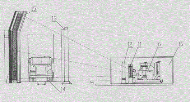
图1为本发明的结构图;Fig. 1 is a structural diagram of the present invention;
图2为本发明加速器架的结构图。Fig. 2 is a structural diagram of the accelerator frame of the present invention.
具体实施方式 Detailed ways
参看图1和图2,本发明系统包括安装在扫描通道内的装有探测器的由一根弯形梁或者由横梁与竖梁组合形式的探测器臂架15、准直器二13和可承载被检查集装货物/车辆通过扫描通道的拖动装置14,以及装有加速器6的加速器架。加速器6的射线正对依次放置的校正器11和准直器一12。准直器一12正对准直器二13使加速器6发出的锥形X射线调节变换为扇形后,穿过被检查物由探测器臂架15内的探测器接收。加速器架是由水平调节机构5、竖直调节机构4、回转调节机构3、俯仰调节机构2以及由底座1、竖臂7、弯型框架8和悬臂9形成的机架组成。其中与底座1相连的水平调节机构5包括横导轨52、手轮五51、丝杠五53和丝母座五54。手轮五51安装在底座1的侧端,手轮五51的转动轴与安装在底座1内的丝杠五53连接,丝杠五53与安装在横导轨52内的丝母座五54螺纹连接,通过螺纹副实现底座1沿横导轨52前后运动。位于与底座1垂直连接的竖臂7中的竖直调节机构4包括竖导轨43、手轮四46、小齿轮41、大齿轮42、丝杠四44和丝母座四45。手轮四46与小齿轮41连接,小齿轮41与大齿轮42啮合形成减速器安装在竖臂7平端面上,大齿轮42的传动轴与安装在竖臂7内的丝杠四44连接,丝杠四44与安装弯型框架8侧臂内的丝母座四45螺纹连接,通过螺纹副实现弯型框架8沿竖导轨43上下运动。位于弯型框架8水平端及与下方所连接的悬臂9之间的回转调节机构3包括手轮三31、齿轮32和回转支撑33。手轮三31安装在弯型框架8上,手轮三31传动轴上安装齿轮32与回转支撑33的内齿圈相啮合,回转支撑33的内圈与悬臂9连接,回转支撑33的外圈与弯型框架8下端面连接,通过回转支撑33的内齿圈实现悬臂9的转动。安装在悬臂9底端的俯仰调节机构2包括手轮二21、蜗轮、蜗杆和加速器支撑架。手轮二21安装在加速器支撑架上,手轮二21与蜗杆连接,蜗杆与蜗轮啮合,蜗轮的转轴与加速器支撑架连接,加速器6通过绞轴与悬臂9和俯仰调节机构2的同轴交点处铰接,通过蜗杆、蜗轮副实现加速器6主束扇面仰角的变化。Referring to Fig. 1 and Fig. 2, the system of the present invention comprises the detector arm frame 15,
在使用中,本发明系统的动作控制首先是给各部装置供电,完成启动状态。当各项指标正常后,由操作人员进行远程控制,让集卡车上载到扫描通道入口处被锚定的拖车装置14上,并卡住集卡车的前轮。启动控制拖动装置14的绞车,由钢丝绳牵引拖车装置14前进,拖车装置14载着集卡车平稳驶向扫描通道。当集卡车进入扫描通道后,加速器6出束进行检测,准直器一12将加速器6发出的锥形X射线调节变换为垂直于地面的扇形束,扇形束穿过集卡车由探测器臂架15内的探测器接收,并将图像信号转换成电信号输入到扫描通道外的图像获取模块中,图像获取模块将图像信号再输送到运行检查器显示图像。检测中或在检测前为了使加速器6发射射线的靶心对准被检集卡车中的嫌疑区域,可根据需要通过加速器架对加速器6的位置及角度进行调节。In use, the action control of the system of the present invention is to supply power to each device at first to complete the startup state. After each index was normal, the operator carried out remote control to allow the collection truck to be uploaded to the anchored trailer device 14 at the entrance of the scanning passage, and block the front wheels of the collection truck. Start the winch that controls the dragging device 14, and the trailer device 14 is advanced by the wire rope traction, and the trailer device 14 is carrying the collection truck and sails to the scanning channel smoothly. When the collection truck enters the scanning channel, the
通过水平调节机构5中手轮五51的转动带动连在它中心轴的丝杠五53旋转,底座1通过它内腔壁上丝母座五54螺纹与丝杠五53螺纹的配合,沿着它下方的横导轨52前进或后退,将加速器6与被检区域的水平距离调整到合适距离。通过竖直调节机构4的中手轮四46的转动带动小齿轮41旋转,小齿轮41将旋转运动传递到大齿轮42,带动与大齿轮42连接的丝杠四44转动,丝杠四44带动安装在弯型框架8侧臂内的丝母座四45移动,带动弯型框架8沿竖臂7的竖导轨43上升或下降。通过转动回转调节机构3的手轮三31,在连动机构的带动下齿轮32旋转,使回转支撑33相连的悬臂9及其下方的加速器6一起绕悬臂纵轴水平旋转,直到射线平面对准被检区域。通过对俯仰调节机构2中手轮二21的转动带动它轴线下方的蜗杆旋转,蜗杆与竖直放置的蜗轮啮合,带动蜗轮及通过支撑架与它相连的加速器6一起沿蜗轮的中心轴在竖直平面内旋转,加速器6发射主束的俯仰角发生变化。经过上述的调整步骤后,将加速器6发射射线的靶心对准被检集卡车中的嫌疑区域,即可得到该位置的清晰图像。The rotation of the
检测完毕后,加速器6停止出束,拖动装置14载着集卡车驶出扫描通道。当拖动装置14到达扫描通道出口处并被锚定住后,集卡车从拖动装置14上下载,本发明系统完成一个扫描程序。After the detection is completed, the
Claims (6)
Priority Applications (5)
| Application Number | Priority Date | Filing Date | Title |
|---|---|---|---|
| CNB2003101001821A CN100437097C (en) | 2003-10-16 | 2003-10-16 | A Containerized Cargo/Vehicle Inspection System with Adjustable Radiation Ray Angle |
| GB0607192A GB2424561B (en) | 2003-10-16 | 2004-09-22 | A containers/vehicles inspection system with adjustable radiation X-ray angle |
| PCT/CN2004/001076 WO2005043144A1 (en) | 2003-10-16 | 2004-09-22 | A containerized cargo/vehicle inspection system in which the angle of radiation beam is adjustable |
| DE112004001701T DE112004001701T5 (en) | 2003-10-16 | 2004-09-22 | System for inspection of goods in containers / wagons with adjustable irradiation angle |
| US10/575,667 US7386092B2 (en) | 2003-10-16 | 2004-09-22 | Containers/vehicle inspection system with adjustable radiation x-ray angle |
Applications Claiming Priority (1)
| Application Number | Priority Date | Filing Date | Title |
|---|---|---|---|
| CNB2003101001821A CN100437097C (en) | 2003-10-16 | 2003-10-16 | A Containerized Cargo/Vehicle Inspection System with Adjustable Radiation Ray Angle |
Publications (2)
| Publication Number | Publication Date |
|---|---|
| CN1607386A CN1607386A (en) | 2005-04-20 |
| CN100437097C true CN100437097C (en) | 2008-11-26 |
Family
ID=34529388
Family Applications (1)
| Application Number | Title | Priority Date | Filing Date |
|---|---|---|---|
| CNB2003101001821A Expired - Fee Related CN100437097C (en) | 2003-10-16 | 2003-10-16 | A Containerized Cargo/Vehicle Inspection System with Adjustable Radiation Ray Angle |
Country Status (5)
| Country | Link |
|---|---|
| US (1) | US7386092B2 (en) |
| CN (1) | CN100437097C (en) |
| DE (1) | DE112004001701T5 (en) |
| GB (1) | GB2424561B (en) |
| WO (1) | WO2005043144A1 (en) |
Families Citing this family (49)
| Publication number | Priority date | Publication date | Assignee | Title |
|---|---|---|---|---|
| US8275091B2 (en) | 2002-07-23 | 2012-09-25 | Rapiscan Systems, Inc. | Compact mobile cargo scanning system |
| US7963695B2 (en) | 2002-07-23 | 2011-06-21 | Rapiscan Systems, Inc. | Rotatable boom cargo scanning system |
| GB0525593D0 (en) | 2005-12-16 | 2006-01-25 | Cxr Ltd | X-ray tomography inspection systems |
| US8243876B2 (en) | 2003-04-25 | 2012-08-14 | Rapiscan Systems, Inc. | X-ray scanners |
| US9113839B2 (en) | 2003-04-25 | 2015-08-25 | Rapiscon Systems, Inc. | X-ray inspection system and method |
| US8837669B2 (en) | 2003-04-25 | 2014-09-16 | Rapiscan Systems, Inc. | X-ray scanning system |
| US7949101B2 (en) | 2005-12-16 | 2011-05-24 | Rapiscan Systems, Inc. | X-ray scanners and X-ray sources therefor |
| GB0309385D0 (en) * | 2003-04-25 | 2003-06-04 | Cxr Ltd | X-ray monitoring |
| US8804899B2 (en) | 2003-04-25 | 2014-08-12 | Rapiscan Systems, Inc. | Imaging, data acquisition, data transmission, and data distribution methods and systems for high data rate tomographic X-ray scanners |
| GB0309379D0 (en) | 2003-04-25 | 2003-06-04 | Cxr Ltd | X-ray scanning |
| US8451974B2 (en) | 2003-04-25 | 2013-05-28 | Rapiscan Systems, Inc. | X-ray tomographic inspection system for the identification of specific target items |
| US8223919B2 (en) | 2003-04-25 | 2012-07-17 | Rapiscan Systems, Inc. | X-ray tomographic inspection systems for the identification of specific target items |
| US6928141B2 (en) | 2003-06-20 | 2005-08-09 | Rapiscan, Inc. | Relocatable X-ray imaging system and method for inspecting commercial vehicles and cargo containers |
| CN100573114C (en) * | 2004-11-26 | 2009-12-23 | 同方威视技术股份有限公司 | A kind of scan arm rigidization vibration-proof structure of radiant image train detection system |
| US7471764B2 (en) | 2005-04-15 | 2008-12-30 | Rapiscan Security Products, Inc. | X-ray imaging system having improved weather resistance |
| JP2007178364A (en) * | 2005-12-28 | 2007-07-12 | Hitachi Ltd | Nuclear medicine diagnostic equipment |
| DE102006051087A1 (en) * | 2006-04-13 | 2007-10-18 | Christoph Clemens Grohmann | By radiation scanners |
| CN101071109B (en) * | 2006-05-08 | 2010-05-12 | 清华大学 | A Cargo Security Inspection System Based on Multi-segment Linear Trajectory Imaging |
| US7742568B2 (en) * | 2007-06-09 | 2010-06-22 | Spectrum San Diego, Inc. | Automobile scanning system |
| CN101441183B (en) * | 2007-11-20 | 2011-08-24 | 同方威视技术股份有限公司 | Trailer safety checking system |
| GB0803641D0 (en) | 2008-02-28 | 2008-04-02 | Rapiscan Security Products Inc | Scanning systems |
| GB0803644D0 (en) | 2008-02-28 | 2008-04-02 | Rapiscan Security Products Inc | Scanning systems |
| GB0809110D0 (en) | 2008-05-20 | 2008-06-25 | Rapiscan Security Products Inc | Gantry scanner systems |
| US8180138B2 (en) * | 2009-03-23 | 2012-05-15 | Morpho Detection, Inc. | Method and system for inspection of containers |
| WO2010114518A1 (en) * | 2009-03-31 | 2010-10-07 | Spectrum San Diego, Inc. | Automobile scanning system |
| US8314394B1 (en) | 2009-11-04 | 2012-11-20 | Science Applications International Corporation | System and method for three-dimensional imaging using scattering from annihilation coincidence photons |
| US8586955B2 (en) | 2010-09-22 | 2013-11-19 | Ko Khee Tay | Apparatus and method for attenuating high energy radiation based on detected vehicle type |
| US9218933B2 (en) | 2011-06-09 | 2015-12-22 | Rapidscan Systems, Inc. | Low-dose radiographic imaging system |
| DE102012107815A1 (en) | 2012-08-24 | 2014-02-27 | Gottwald Port Technology Gmbh | Method and system for non-contact control of containers, in particular ISO containers, within a handling facility |
| JP6385369B2 (en) | 2013-01-31 | 2018-09-05 | ラピスカン システムズ、インコーポレイテッド | Transportable safety inspection system |
| RO130582B1 (en) * | 2014-01-23 | 2021-12-30 | Mb Telecom Ltd. S.R.L. | System and method for complete and non-intrusive inspection of aircrafts |
| CN104133251B (en) | 2014-07-04 | 2017-08-25 | 清华大学 | Portable back scattering imaging rays safety detection apparatus and method |
| CN104101910A (en) * | 2014-07-04 | 2014-10-15 | 清华大学 | Distributed radiation source-based X-ray backscattering channel type vehicle security system and method |
| CN105894052A (en) * | 2014-10-21 | 2016-08-24 | 上海贞易信息技术有限公司 | RFID (Radio Frequency Identification) based cargo transportation and checkout system |
| CN105675042B (en) * | 2015-12-28 | 2018-08-10 | 同方威视技术股份有限公司 | Ray caliberating device and its operating method, radiation image-forming system and its operating method |
| CN106908849B (en) * | 2017-03-30 | 2021-01-29 | 北京华力兴科技发展有限责任公司 | Detection device for bus luggage compartment |
| CN108413194A (en) * | 2018-03-14 | 2018-08-17 | 中国工程物理研究院激光聚变研究中心 | Regulating device, X-ray detector and X-ray detection system |
| CN108956652B (en) * | 2018-04-04 | 2023-12-12 | 中国南方电网有限责任公司超高压输电公司曲靖局 | Electric strain clamp and splicing sleeve crimping quality exploration device |
| CN109521480A (en) * | 2019-01-04 | 2019-03-26 | 同方威视科技(北京)有限公司 | Radiation examination device and radiation testing method |
| CN109799249B (en) * | 2019-02-27 | 2024-02-23 | 中国工程物理研究院机械制造工艺研究所 | Vehicle-mounted CT nondestructive testing system |
| CN109814164A (en) * | 2019-03-13 | 2019-05-28 | 北京华力兴科技发展有限责任公司 | Vehicle inspection equipment |
| CN110057848A (en) * | 2019-04-17 | 2019-07-26 | 苏州曼德克光电有限公司 | A kind of system and method being aligned for detector array with radiographic source |
| CA3149539A1 (en) | 2019-09-16 | 2021-03-25 | Voti Inc. | Probabilistic image analysis |
| CN110850494A (en) * | 2019-10-24 | 2020-02-28 | 武汉艾崴科技有限公司 | double-X-light-source side-lighting type security inspection machine for large-sized automobile container |
| CN112083510A (en) * | 2020-08-13 | 2020-12-15 | 许昌瑞示电子科技有限公司 | Ray detection equipment and corner detector assembly thereof |
| CN114764069B (en) * | 2020-12-31 | 2024-10-11 | 同方威视技术股份有限公司 | Radiation inspection system |
| CN119031563B (en) * | 2024-09-25 | 2025-03-28 | 山东蓝孚高能物理技术股份有限公司 | A fixing device for electron linear accelerator |
| CN119510456A (en) * | 2024-11-28 | 2025-02-25 | 同方威视技术股份有限公司 | Testing equipment |
| CN119620213A (en) * | 2024-12-16 | 2025-03-14 | 同方威视技术股份有限公司 | Radiographic inspection system |
Citations (6)
| Publication number | Priority date | Publication date | Assignee | Title |
|---|---|---|---|---|
| US4599740A (en) * | 1983-01-06 | 1986-07-08 | Cable Arthur P | Radiographic examination system |
| US4841554A (en) * | 1987-03-11 | 1989-06-20 | Heimann Gmbh | X-ray scanner for inspecting articles moving therethrough |
| JPH08166359A (en) * | 1994-12-15 | 1996-06-25 | Hitachi Medical Corp | System for inspecting article unsuitable to handle at garbage-disposal facility |
| CN1197209A (en) * | 1998-04-03 | 1998-10-28 | 清华大学 | Vehicle-mounted γ-ray digital radiation imaging mobile detection station and its array detection device |
| CN2403020Y (en) * | 1999-12-17 | 2000-10-25 | 清华同方股份有限公司 | Radiation source-collimator-detector integrated structure of container scanning device |
| CN2706362Y (en) * | 2003-10-16 | 2005-06-29 | 清华大学 | Container goods/vehicle inspection equipment capable of regulating radiation angle |
Family Cites Families (6)
| Publication number | Priority date | Publication date | Assignee | Title |
|---|---|---|---|---|
| US5764683B1 (en) * | 1996-02-12 | 2000-11-21 | American Science & Eng Inc | Mobile x-ray inspection system for large objects |
| US6763635B1 (en) * | 1999-11-30 | 2004-07-20 | Shook Mobile Technology, Lp | Boom with mast assembly |
| CN1160557C (en) * | 2001-09-03 | 2004-08-04 | 北京埃索特核电子机械有限公司 | Equipment of cobalt 60 gamma ray source-cesium iodide or cadmium tungstate detector for checking container |
| CN1184468C (en) | 2002-10-16 | 2005-01-12 | 清华大学 | Mechanical vehicle ray camera testing systems |
| US7133491B2 (en) * | 2004-01-15 | 2006-11-07 | Bio-Imaging Research, Inc. | Traveling X-ray inspection system with collimators |
| CN100573114C (en) * | 2004-11-26 | 2009-12-23 | 同方威视技术股份有限公司 | A kind of scan arm rigidization vibration-proof structure of radiant image train detection system |
-
2003
- 2003-10-16 CN CNB2003101001821A patent/CN100437097C/en not_active Expired - Fee Related
-
2004
- 2004-09-22 DE DE112004001701T patent/DE112004001701T5/en not_active Ceased
- 2004-09-22 WO PCT/CN2004/001076 patent/WO2005043144A1/en not_active Ceased
- 2004-09-22 GB GB0607192A patent/GB2424561B/en not_active Expired - Lifetime
- 2004-09-22 US US10/575,667 patent/US7386092B2/en not_active Expired - Lifetime
Patent Citations (6)
| Publication number | Priority date | Publication date | Assignee | Title |
|---|---|---|---|---|
| US4599740A (en) * | 1983-01-06 | 1986-07-08 | Cable Arthur P | Radiographic examination system |
| US4841554A (en) * | 1987-03-11 | 1989-06-20 | Heimann Gmbh | X-ray scanner for inspecting articles moving therethrough |
| JPH08166359A (en) * | 1994-12-15 | 1996-06-25 | Hitachi Medical Corp | System for inspecting article unsuitable to handle at garbage-disposal facility |
| CN1197209A (en) * | 1998-04-03 | 1998-10-28 | 清华大学 | Vehicle-mounted γ-ray digital radiation imaging mobile detection station and its array detection device |
| CN2403020Y (en) * | 1999-12-17 | 2000-10-25 | 清华同方股份有限公司 | Radiation source-collimator-detector integrated structure of container scanning device |
| CN2706362Y (en) * | 2003-10-16 | 2005-06-29 | 清华大学 | Container goods/vehicle inspection equipment capable of regulating radiation angle |
Also Published As
| Publication number | Publication date |
|---|---|
| DE112004001701T5 (en) | 2006-07-13 |
| GB0607192D0 (en) | 2006-05-17 |
| WO2005043144A1 (en) | 2005-05-12 |
| CN1607386A (en) | 2005-04-20 |
| GB2424561A (en) | 2006-09-27 |
| GB2424561B (en) | 2007-07-04 |
| US7386092B2 (en) | 2008-06-10 |
| US20070133740A1 (en) | 2007-06-14 |
Similar Documents
| Publication | Publication Date | Title |
|---|---|---|
| CN100437097C (en) | A Containerized Cargo/Vehicle Inspection System with Adjustable Radiation Ray Angle | |
| CN100437096C (en) | A double radiation source frame structure for container inspection system | |
| CN100541187C (en) | A Container Inspection System Capable of CT Tomography Scanning | |
| US7352843B2 (en) | Combined mobile container inspection system with low target | |
| CN1185482C (en) | Aeronautical container/tray article examination system | |
| CN101470084B (en) | Jib structure of double-view angle scanning device | |
| CN104101615B (en) | Vehicle-mounted movable detecting system for computed tomography | |
| CN104122276A (en) | Loadable industrial CT (computed tomography) detection device | |
| US20040247075A1 (en) | Vehicle mounted inspection systems and methods | |
| WO2016095774A1 (en) | Towing-type object inspection system with multiple viewing angles and usage method thereof | |
| CN1490616A (en) | A vehicle-mounted mobile container inspection system | |
| CN212872940U (en) | Vehicle-mounted container or truck perspective scanning rapid security inspection device | |
| CN106290422B (en) | Imaging device and method for vehicle safety inspection | |
| CN2706362Y (en) | Container goods/vehicle inspection equipment capable of regulating radiation angle | |
| WO2022143164A1 (en) | Radiation inspection system | |
| CN1116603C (en) | Foldable detector scanning arm device for mobile container detection system | |
| CN2572400Y (en) | Vehicle carried moveable container check system | |
| CN201173902Y (en) | A boom structure of a dual-view scanning device | |
| CN2632671Y (en) | Mechanical structure module container cargo-vehicle tester | |
| CN2715148Y (en) | A composite move type low target point container checking device | |
| CN1779446B (en) | Rotary device of container checking system with CT fault scanning function | |
| CN1114827C (en) | Door frame scanning vehicle for mobile container inspection system | |
| CN100526866C (en) | Container checking system with CT fault scanning function | |
| CN2567568Y (en) | Built-up and dismounted movable gamma ray detection device for container | |
| CN212675197U (en) | A dual-source dual-view passenger vehicle rapid inspection device |
Legal Events
| Date | Code | Title | Description |
|---|---|---|---|
| C06 | Publication | ||
| PB01 | Publication | ||
| C10 | Entry into substantive examination | ||
| SE01 | Entry into force of request for substantive examination | ||
| C14 | Grant of patent or utility model | ||
| GR01 | Patent grant | ||
| CF01 | Termination of patent right due to non-payment of annual fee |
Granted publication date: 20081126 Termination date: 20151016 |
|
| EXPY | Termination of patent right or utility model |