CN100367658C - Closed loop control of linear vibration actuator - Google Patents
Closed loop control of linear vibration actuator Download PDFInfo
- Publication number
- CN100367658C CN100367658C CNB03826062XA CN03826062A CN100367658C CN 100367658 C CN100367658 C CN 100367658C CN B03826062X A CNB03826062X A CN B03826062XA CN 03826062 A CN03826062 A CN 03826062A CN 100367658 C CN100367658 C CN 100367658C
- Authority
- CN
- China
- Prior art keywords
- linear vibration
- lva
- switching element
- back emf
- interface circuit
- Prior art date
- Legal status (The legal status is an assumption and is not a legal conclusion. Google has not performed a legal analysis and makes no representation as to the accuracy of the status listed.)
- Expired - Fee Related
Links
Images


Classifications
-
- G—PHYSICS
- G05—CONTROLLING; REGULATING
- G05D—SYSTEMS FOR CONTROLLING OR REGULATING NON-ELECTRIC VARIABLES
- G05D19/00—Control of mechanical oscillations, e.g. of amplitude, of frequency, of phase
- G05D19/02—Control of mechanical oscillations, e.g. of amplitude, of frequency, of phase characterised by the use of electric means
Landscapes
- Physics & Mathematics (AREA)
- General Physics & Mathematics (AREA)
- Engineering & Computer Science (AREA)
- Automation & Control Theory (AREA)
- Apparatuses For Generation Of Mechanical Vibrations (AREA)
Abstract
The present invention relates to a closed loop control method of a linear vibration exciter. The linear vibration exciter vibrates linearly and provides electrical energy for the linear vibration exciter through a switching element which is driven by a PWM control method. The method comprises the following steps: an apex or a peak point (BC, BP) (S14) of back electromotive force generated in the linear vibration exciter is detected; the apex or the peak point (BC, BP) which is detected is compared with a reference value (Bcr, Bpr), PWM working time (alpha) which is used by the switching element can be adjusted, the working frequency of the linear vibration exciter is controlled to be resonant frequency (S16 to S19), and thereby, the apex or the peak point (BC, BP) of the back electromotive force can always be kept constant.
Description
Technical Field
The invention relates to a closed-loop control technique for a linear vibration actuator by means of a microcontroller.
Background
Recently, a Linear Vibration Actuator (LVA) is being applied to a cellular phone to generate vibration as an alarm for an incoming call. A cross-sectional view of the LVA is shown in fig. 19. LVA100 includes a magnet 101, a weight 103, and a resonant spring 105 carrying magnet 101 and weight 103. As can be appreciated from FIG. 19, the LVA has a vertical (up and down) motion, rather than a horizontal motion, making it very suitable for useFor use in a cellular telephone. When LVA is at a predetermined resonant frequency (f) r ) When operating in an open loop, vibration is generated in the LVA. Resonant frequency (f) of LVA r ) Given by the following formula,

where m is the mass of the weight 103 and k is the spring constant of the spring 105. The sensitivity of the vibration is dependent on the stroke length of the LVA. Typically, most LVAs are designed for resonant frequencies (f) between 135Hz and 170Hz r ) And the sensitivity of the vibration is maintained in the range of 90dB to 110dB. In the prior art, the LVA is driven in an open loop by a transistor with 50% ON-duty and is operated with a power supply of 1.4V. The basic drive circuit of an LVA with one free-running astable multi-oscillator is shown in fig. 20. An astable multivibrator with 50% operating time and varying frequency can be realized by a simple analog and digital circuit, or by the software of a microcontroller. Resonant frequency (f) of LVA r ) Typically varying between +/-8Hz and influenced by the parameters k and m in equation (1). If LVA is always at a constant predetermined resonant frequency (f) r ) Cycling, then in actual operation, the stroke length of the LVA, i.e., the sensitivity to vibration, decreases as the resonant frequency changes. Another such switching control strategy is that since the transistor's Pulse Width Modulation (PWM) on time is always held at a constant 50% and thus the battery charge is drained quicklyOne disadvantage is the high energy consumption of the LVA.
The object of the present invention is to operate the LVA in a closed loop by sensing the back electromotive force (emf) during the off-period of the transistor by means of a microcontroller in order to automatically track the resonant frequency (ff) of the LVA r )。
Disclosure of Invention
According to a first aspect of the present invention, an apparatus for controlling a linear vibration exciter comprises: a switching element for alternately turning on and off to intermittently supply electric power to the linear vibration actuator; a drive circuit for driving the switching element in a pulse width modulation control method; an interface circuit for detecting a counter electromotive force of the linear vibration actuator during an off period of the switching element, the interface circuit being connected between a connection point of the switching element and the linear vibration actuator and an AD input terminal of the controller; and a controller for controlling the driving circuit according to a back electromotive force detection result of the interface circuit, thereby driving the switching element at a resonance frequency; wherein the controller controls the drive circuit to maintain a constant magnitude of a bottom peak or a top peak point of the back emf and to center the pulse width modulation duty cycle on consecutive zero crossings of the back emf.
According to a second aspect of the present invention, a closed-loop control method of a linear vibration actuator that linearly vibrates and is supplied with energy by driving a switching element in a pulse width modulation control method, includes: detecting a bottom peak or a top peak point of a back electromotive force generated in the linear vibration actuator; comparing the bottom peak or the top peak point of the detected back electromotive force with a reference value; and adjusting at least one of parameters of a pulse width modulation operation time applied to the switching element and an operation frequency of the linear vibration exciter so that a bottom peak or a top peak point of the back electromotive force is constant.
According to a third aspect of the present invention, a closed-loop control method of a linear vibration actuator that linearly vibrates and that supplies energy to the linear vibration actuator by driving a switching element in a pulse width modulation control method, includes: detecting a zero-crossing point in a negative slope region of a back electromotive force occurring in the linear vibration actuator; calculating the working frequency of the linear vibration exciter according to the period between two continuous zero crossing points in the negative slope region of the back electromotive force; and turning on the switching element after a turn-on delay has elapsed from a time point after the detection of the zero-crossing point of the back electromotive force, and thereby updating the turn-on delay according to the calculated operating frequency so that the pulse width modulation operating time is located at the center of the sum of two consecutive zero-crossing points, driving the switching element with the calculated operating frequency, and continuously adjusting the pulse width modulation operating time after sensing and comparing the top peak or bottom peak point of the back electromotive force with the value of the reference top peak or reference bottom peak point of the back electromotive force
According to a fourth aspect of the present invention, a closed-loop control method of a linear vibration actuator which linearly vibrates and is supplied with energy by driving a switching element in a pulse width modulation control method, comprises: detecting a zero-crossing point in a positive slope region and a zero-crossing point in a negative slope region of a back electromotive force occurring in the linear vibration actuator; estimating a turn-off delay from a zero crossing in the positive slope region, the turn-off delay being a time interval between a turn-off time of the pulse width modulated working pulse and a time at which the zero crossing in the positive slope region is detected; varying the turn-on delay so as to make the turn-on delay substantially equal to the turn-off delay; and driving the switching element to turn on when a turn-on delay elapses after detecting the zero-crossing point in the negative slope region, and continuously adjusting the pulse width modulation operating time after sensing a top peak or a bottom peak point of the back electromotive force and comparing it with a value of a reference top peak or a reference bottom peak point of the back electromotive force.
According to a fifth aspect of the present invention, a closed-loop control method of a linear vibration actuator that linearly vibrates and is supplied with energy by driving a switching element in a pulse width modulation control method, includes: detecting a top peak or a bottom peak point of a back electromotive force generated in the linear vibration actuator; defining a turn-on delay from a top peak or a bottom peak point of the detected back emf; calculating the working frequency of the linear vibration exciter according to the period between two continuous top peak values or bottom peak values of the back electromotive force; and driving the switching element using the calculated operating frequency, turning on the switching element when a turn-on delay elapses after detecting a top peak or a bottom peak of the back electromotive force.
According to a sixth aspect of the present invention, a closed-loop control method of a linear vibration actuator that linearly vibrates and is supplied with energy by driving a switching element in a pulse width modulation control method, includes: detecting a top peak or a bottom peak point of a back electromotive force generated in the linear vibration actuator; defining a turn-on delay and a turn-off delay from a top peak or a bottom peak point of the detected back emf, the turn-off delay being a time interval between a turn-off instant of the pulse width modulated working pulse and an instant corresponding to the top peak or the bottom peak point of the back emf); varying the turn-on delay to make the turn-on delay equal to the turn-off delay; and driving the switching element to turn on the switching element when a turn-on delay elapses after the top peak or the bottom peak point of the back electromotive force is detected.
Drawings
FIG. 1 illustrates a first driver circuit including a first interface circuit for closed loop control of an LVA in accordance with the present invention;
FIG. 2 shows the back emf of the LVA and the PWM pulse waveform at the A/D input of the microcontroller of the first drive circuit;
FIG. 3A illustrates a second driver circuit including a second interface circuit for closed loop control of the LVA according to the present invention;
FIG. 3B illustrates a third driver circuit including a third interface circuit for closed loop control of the LVA in accordance with the present invention;
FIG. 4 shows the back emf of the LVA and the PWM pulse waveform at the A/D input of the microcontroller of the second interface circuit;
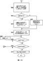
fig. 5 shows a flow chart of a first algorithm of the LVA control method according to the present invention;
FIG. 6 shows the back emf of the LVA and the waveform of the PWM pulses at the A/D input of the microcontroller of the first algorithm;
fig. 7 shows a flow chart of a second algorithm of the LVA control method according to the present invention;
FIG. 8 shows the back emf of the LVA and the waveform of the PWM pulses at the A/D input of the microcontroller of the second algorithm;
fig. 9 shows a flow chart of a third algorithm of the LVA control method according to the present invention;
FIG. 10 shows the back emf of the LVA and the waveform of the PWM pulses at the A/D input of the microcontroller of the third algorithm;
11A and 11B show a flow chart of a fourth algorithm of the LVA control method according to the present invention;
FIG. 12 shows the back emf of the LVA and the PWM pulse waveform at the A/D input of the microcontroller of the fifth algorithm;
fig. 13A to 13C show a flow chart of a fifth algorithm of the control method of the LVA according to the present invention;
fig. 14 shows the back emf of the LVA at the a/D input of the microcontroller of the sixth or seventh algorithm and the waveform of the PWM pulse;
15A and 15B show a flow chart of a sixth algorithm of the control method of the LVA according to the present invention;
fig. 16A and 16B show a flow chart of a seventh algorithm of the control method of the LVA according to the present invention;
fig. 17 shows a cellular phone including a vibrator including an LVA and a driving circuit for driving the LVA according to the present invention;
FIGS. 18A and 18B illustrate a game controller including a vibrator comprising an LVA and a drive circuit for driving the LVA in accordance with the present invention;
FIG. 18C shows a massage belt including vibrators incorporating LVAs and drive circuits for driving the LVAs in accordance with the present invention;
fig. 19 shows a cross-sectional view of a linear vibration exciter (LVA); and
fig. 20 shows a conventional open-loop driver circuit for the LVA.
Detailed Description
Preferred embodiments of the present invention are described below with reference to the accompanying drawings.
1. Hardware configuration
Fig. 1 shows an example of a drive circuit of a Linear Vibration Actuator (LVA) according to the present invention. The driving circuit driving the LVA11 in the closed-loop control includes a driving transistor QN1, an interface circuit 20a detecting a back electromotive force (emf) of the LVA11, a microcontroller 30 controlling an operation of the driving transistor QN1, and a switch driver 40 driving the transistor QN1 according to a control signal from the microcontroller 30.
LVA11 preferably operates at supply voltages ranging from 1.4V to 4.2V.
The interface circuit 20a includes an operational amplifier 21 between the collector of the drive transistor QN1 and the a/D input of the microcontroller 30. The interface circuit 20a further includes a resistance voltage dividing circuit including resistors R2 and R3, and a resistance voltage dividing circuit including resistors R4 and R5. The transistor QN1 is driven from the output port of the micro controller 30. The operational amplifier 21 functions as a level shifter and determines the zero-crossing level by a resistance voltage dividing circuit including resistors R4 and R5. The gain of operational amplifier 21 is adjusted to obtain accurate a/D sensing. The inverse back emf of the LVA11 with zero crossing levels as seen at the a/D input of the microcontroller 30 is shown in fig. 2.
The closed loop operation of the LVA11 may be performed by a different algorithm to be described later. All of these algorithms require a back emf peak point (B) defined from the zero crossing level c ) Is detected. It is also desirable that the zero crossing (Z) occur in the negative and positive emf slope regions, respectively 0 ) And (Z) 1 ) So as to be always at the resonance frequency (f) r ) The LVA11 is operated.
FIG. 3A shows a second interface including a back emf to detect LVA11Another example of a driver circuit for a port circuit. The second interface circuit 20b includes clamping diodes D1 and D2, and a filter circuit including a resistor R and a capacitor C and connected between the collector of the driving transistor QN1 and the a/D output terminal of the microcontroller 30. The back emf of the LVA11 seen at the a/D input of the microcontroller 30 is shown in fig. 4. The zero-crossing level is determined by the supply voltage V of the exciter 11 m And (6) determining.
Fig. 3B shows another example of a driver circuit including a third interface circuit, in which a resistor divider network made up of R1 and R2 is added to the configuration shown in fig. 3A. Such a resistor divider network in the third interface circuit 20c may convert the magnitude of the back emf to a compatible a/D sensing level for the microcontroller 30.
With a driver circuit having the interface circuit shown in fig. 3A or 3B, the closed loop operation of the LVA11 can be performed using various algorithms as described below. In this case, all these algorithms require back emf peak points (B) defined from the zero crossing level p ) Is detected. Also, in order to always operate the LVA at the resonant frequency (f) r ) It is also desirable to have zero crossing (Z) occur in the positive and negative back emf slope regions, respectively 0 ) And (Z) 1 ) Time of day information.
Inverted back emf bottom peak point (B) detected by the above interface circuit c ) Or back emf top peak point (B) p ) Is proportional to the stroke length or sensitivity of the vibration of the LVA. Thus, the closed loop operation of the LVA11 is performed to maintain the back emf bottom peak point (B) c ) Or back emf top peak point (B) p ) And the PWM operation time is at two zero-crossing points (Z) 0 ) And (Z) 1 ) As shown in fig. 2 and 4. This automatically ensures that the LVA11 always operates at the resonance frequency (f) with the minimum PWM on-time r ) Thus also ensuring an efficient operation of the energy.
2. Control method
Some embodiments of the control method for the LVA of the driver circuit including the second interface circuit 20b are described below. However, the following embodiments are also effective for a drive circuit including the first or third interface circuit with necessary modifications.
According to the following control method, the LVA is operated under closed-loop control by sensing its back electromotive force (emf) in the transistor off period so as to automatically track the operating resonant frequency (ff) r ). Thus, the stroke length or vibration sensitivity of the LVA is always constant regardless of the change in the battery voltage or the application of the external damping force during the closed-loop control. The use of microcontrollers in commercially available cellular telephones and the like greatly supports the implementation of closed loop control. The back emf can be easily sensed with an a/D converter within the microcontroller. Thus, the control technique can be realized without a large additional cost.
The LVA preferably operates at a resonant frequency at a higher cell voltage (2.9V to 4.2V) and a lower on-time (10% to 15%), thereby providing a stroke length equal to that when operating at a lower cell voltage (1.2V to 1.6V) and a higher on-time (40% to 50%), i.e., sensitivity to vibration. The average current through the LVA is the same in both cases, making the LVA more energy efficient when operated at higher cell voltages.
2.1 first embodiment of the control method
A first algorithm of the control method of the LVA11 in which the PWM operating time is changed stepwise in accordance with the detected back emf of the LVA11 while the operating frequency of the LVA11 is constant is explained below.
The first algorithm has the following salient features.
(i) LVA always operates at a predetermined constant resonant frequency (f) rc )。
(ii) The initial PWM on-time (α) at start-up is also predetermined.
(iii) These parameters (f) rc And α) a suitable reference back emf top peak point (B) dependent on the LVA characteristic pr ) And a requested start response. It should be noted thatNumber (f) rc And α) and other parameters are stored in advance in a data storage device of the control apparatus, for example, a ROM (or hard disk) of the microcontroller.
(iv) The LVA is under closed loop operation from the first cycle, and continuously senses the back emf top peak point (B) p ) And with the reference back emf top peak point (B) pr ) The values of (a) are compared. If B is present p And B pr Exceeds a predetermined tolerance value (δ), the PWM on-time (α) is varied stepwise with a small percentage of the PWM on-time equal to (Δ α) until a back emf top peak point (B) p ) Again close to the reference value (B) pr ) So that the sensitivity of the vibration is unchanged.To make closed loop control more reliable, LVA11 is defined with an upper limit (α) for PWM on-time max ) And lower limit (α) min ). The value of Δ α, which is highly dependent on the system design, may remain constant at all times, or may be relative to B p And B pr The magnitude of the error therebetween changes proportionally.
The first algorithm is explained in detail below with reference to fig. 5. It should be noted that the following procedure is executed by the microcontroller 30.
When a start switch of a control device is turned on (S11), values of several parameters are read from a data storage device of the control device (S12). According to the initialized PWM duty, a PWM duty is set (S13). Detecting back emf top peak B at each PWM idle period by using interface circuit p (S14). Back emf peak value B to be detected p And reference back emf top peak B pr The error therebetween is compared with the fault tolerance delta (S15).
If the detected back emf top peak B p And reference back emf top peak B pr Error between (| B) p -B pr |) is within the fault tolerance δ (S15), then the percentage of on-time α is not changed (S16). If error (| B) p -B pr |) exceeds the fault tolerance δ (S15), the percentage of the on-time α is changed. I.e., if B p >B pr (S17), then the operating time alpha is reducedSmaller by a predetermined value Δ α, and otherwise increased by a predetermined value Δ α (S19). The microcontroller 30 then instructs the switch driver to drive the transistor QN1 for the resulting on-time α.
The above-described process is repeated (S13 to S19) while the start switch is kept on (S20). When the start switch is turned off, the output of the PWM operation pulse is terminated (S21).
Fig. 6 shows the waveform of back emf of the LVA11 when the above-described control method is applied to the device shown in fig. 3A. As can be seen from fig. 6, the percentage of the on-time α is changed by a predetermined value Δ α in order to maintain the back emf top peak B p Constant (= B) pr )。
2.2 second embodiment of the control method
A second algorithm of the control method of the LVA11 is explained below, in which the operating frequency of the LVA11 is changed stepwise in accordance with the detected back emf of the LVA11, and the PWM operating time is constant.
With reference to fig. 7, the salient features of the second algorithm of the LVA11 control method are explained as follows.
(i) LVA11 always operates at a predetermined fixed PWM operation time (alpha) c ). After the switch is switched on, the fixed PWM operating time (alpha) is first read c ) And other parameters (S32).
(ii) The operating frequency of the LVA during start-up is equal to a predetermined resonance frequency (f) r )。
(iii) Parameter (alpha) c And f r ) Appropriate reference back emf top peak point (B) depending on LVA behavior pr ) And the desired start response.
(iv) The LVA is in closed-loop operation from the first cycle and continuously senses the back emf top peak point (B) p ) Size of (S34), and back emf top peak point (B) p ) And reference back emf top peak point (B) pr ) And (S35) comparing. If (B) p ) And (B) pr ) With the error between exceeding a predetermined tolerance value (delta), is stepped by a small percentage of the resonance frequency equal to (deltaf)Changing the operating frequency (S37 to S39) until the back emf top peak point (B) p ) Approach the reference value (B) again pr ) So that the sensitivity of the vibration is unchanged. If (B) p ) And (B) pr ) The error between is within the tolerance delta, then the operating frequency f is not changed r Percent (S36). The above-described process is repeated (S33 to S39) while keeping the starting switch on (S40).
To make closed loop control more reliable, an upper limit (f) of the resonant frequency is defined for the LVA rmax ) And lower limit (f) rmin ). The value of (Δ f), which is highly dependent on the system design, may remain constant at all times, or may be relative to (B) p ) And (B) pr ) The magnitude of the error therebetween changes proportionally.
Fig. 8 shows the waveform of back emf of the LVA under the second algorithm. As can be seen from FIG. 8, the operating frequency f is adjusted r The predetermined value (Δ f) is changed so as to make the back emf top peak value B p And remain constant.
2.3 third embodiment of the control method
The third algorithm of the control method of the LVA11 is explained below with reference to fig. 9 showing the flow of the third algorithm.
Referring to fig. 9, unlike the first and second algorithms, the PWM operating time (α) and the resonance frequency (f) r ) Simultaneously changing (S58, S59) so as to make back emf top peak point (B) p ) Always following the reference back emf top peak point (B) pr ). The simultaneous change of these two parameters also ensures that the PWM operating time is always at the zero crossing (Z) 0 ) And (Z) 1 ) The center between.
2.4 fourth embodiment of the control method
A fourth algorithm of the control method of the LVA11 is explained below, in which the open-loop operation is first performed for a predetermined number of cycles (N) and then the closed-loop operation is performed. In closed loop operation, a turn-on delay (t) is set ond ) So as to enable the PWM on-time pulse to be negative of back emfZero crossing point Z in slope 1 Zero crossing Z in positive slope with back emf 0 The center of the space between. Switch-on delay (t) ond ) Is the zero crossing Z from the negative slope of back emf 1 Time interval to the start of the PWM on-time pulse.
With reference to fig. 11A and 11B, the salient features of the fourth algorithm are explained as follows.
(i) LVA11 starts in an open loop operation with a predetermined initial PWM on-time (α). As can be seen from the flow shown in fig. 11A and 11B, both the open-loop and closed-loop operation modes are determined according to the number of cycles (N) (S75, S84).
(ii) Zero crossing (Z) in negative slope region where back emf is sensed 1 ) Then the driving transistor QN1 is always turned on (S73), and the turn-on delay (t) as shown in fig. 10 is provided (t) ond ) (S84, S86). The turn-on delay indirectly controls the operating frequency of the LVA11.
(iii) Starting PWM on-time (alpha) and initial turn-on delay (t) during open loop operation ond ) Kept constant (S78). The values of these two parameters depend on the LVA behavior, with appropriate reference to the back emf top peak point (B) pr ) And a required startup response. After several initial cycles equal to (N), the LVA enters closed-loop operation (S75, S84).
(iv) Continuously sensing back emf top peak point (B) during closed loop operation p ) Is determined (S76), and is compared with the reference back emf top peak point (B) pr ) The values of (S77) are compared. If (B) p ) And (B) pr ) Exceeds a predetermined allowable value (δ) (S77), the PWM on-time is changed stepwise with a small percentage of the PWM on-time equal to Δ α (S79, S80, S81) until a back-emf top peak point (B) p ) Again close to the reference value (B) pr ) (S77). Therefore, the sensitivity of the vibration does not change. To make closed loop control more reliable, the LVA11 is defined with an upper limit (alpha) of the PWM on-time (alpha) max ) And lower limit (alpha) min ) (refer to S80, 81). The value of Δ α, which is highly dependent on the system design, can be kept constant at all times, or relative to the error (| B) pr -B pr |) vary in size proportionally.
(v) By detecting two successive zero-crossings (Z) during closed-loop operation 1 ) The operating frequency of the LVA11 is calculated during the time period (S82, S83). The turn-on delay is continuously updated (S85) with respect to the operating frequency so that the PWM operating time is always at two zero crossings (Z) 0 ) And (Z) 1 ) Is located in the center of (1). This indirectly ensures that the LVA operates at the resonant frequency (f) r ). Switch-on delay t in closed loop operation ond Is given by the formula (T) r /4- α/2) wherein T is r Is equal to 1/f r . When passing from zero-crossing Z of back emf in negative slope 1 Has passed through the turn-on delay t ond In one period of (3), the transistor QN1 is drivenAnd (4) switching on. In the present embodiment, the turn-on delay t ond Is formed by a counter t accumulating the clock count And (4) measuring.
2.5 fifth embodiment of control method
The fifth algorithm of the control method of the LVA11 is explained below. The aforementioned distinctive features (i) to (iv) of the fourth algorithm are also the same for the fifth algorithm. The main difference between the fourth and fifth algorithms is that another zero crossing (Z) in the positive slope region of the back emf is sensed during closed loop operation 0 ) To estimate the disconnection delay (t) online offd ) And delaying the switch-on (t) ond ) Equal to the turn-off delay (t) offd ) As shown in fig. 12.
The salient features of the following fifth algorithm are explained in detail with reference to fig. 13A to 13C.
(i) In closed loop operation, by accumulating the time from the moment of PWM pulse turn-off until detection of back emf zero-crossing (Z) 0 ) Clock of time of (a), estimating or recording the disconnection delay (t) offd )(S106,S109)。
(ii) If the set switch-on delay (t) ond ) With estimated disconnect delay (t) offd ) The error therebetween exceeds a predetermined allowable value (epsilon) (S118), the turn-on delay (t) is changed stepwise with a small period equal to (deltat) ond ) (S120, S122) so that it is again approximately equal to the turn-off delay (t) offd ). If the difference does not exceed the tolerance value (epsilon), the turn-on delay (t) is not changed ond ) (S119). The value of (Δ t), which is highly dependent on the system design, may remain constant at all times, or may be relative to (t) ond ) And (t) offd ) The magnitude of the error therebetween changes proportionally. This algorithm directly ensures that the PWM duty time is always at two zero crossings (Z) 0 ) And (Z) 1 ) Thus, the LVA is made to operate at the resonance frequency (f) r )。
When a zero crossing point (Z) is detected 1 ) After which a turn-on delay (t) has elapsed ond ) One period of time, one PWM pulse output is generated (S124 to S126).
2.6 sixth embodiment of control method
A sixth algorithm example of the LVA11 control method is described below. The features of the sixth algorithm are substantially the same as the fourth algorithm. In the sixth algorithm, the turn-on delay (t) ond ) Is based on back emf top peak point (B) p ) And (4) defining.
A flowchart of the sixth algorithm is shown in fig. 15A and 15B. As shown in the flow chart, in the sixth algorithm, the zero-crossing point (Z) is not sensed 1 ). The frequency of operation of the LVA11 is determined by recording two consecutive pulsesBack emf peak point of (B) p ) The time period therebetween is calculated (S151). Switch-on delay (t) ond ) Is relative to the resonance frequency f r From back emf top peak point (B) p ) Defined (S152), as shown in fig. 14. It should be noted that the turn-on delay (t) ond ) Can be passed through (T) r The/4-alpha/2) definition.
2.7 seventh embodiment of control method
The seventh algorithm of the control method of the LVA11 is described below. The features of the seventh algorithm are substantially the same as the fifth algorithm. In the seventh algorithm, the zero-crossing point (Z) is not sensed 0 ) And (Z) 1 ) And as shown in fig. 14, from the back emf top peak point (B) p ) Defining a turn-on delay (t) ond ) And a disconnection delay (t) offd ). The seventh algorithm is shown in fig. 16A and 16BAnd (4) a flow chart.
As shown in the flow chart, the turn-off delay (t) offd ) Is through the back emf top peak point (B) p ) Is known by the detection time of (c). That is, the turn-off delay (t) offd ) Is measured from the end time of the PWM pulse to the detection of the back emf top peak point (B) p ) Is counted (S175 to S178). So that the switch-on is delayed (t) ond ) Equal to the turn-off delay (t) offd ) (S180 to S184).
3. Industrial and commercial availability
Since the sensitivity of vibration is always kept constant, the above-described closed-loop control of the LVA can be used to generate vibration in a cellular phone, a game controller, a massage belt, or the like. All of these systems have a microcontroller that facilitates closed loop control of the LVA without adding any cost.
Fig. 17 shows an example of using the LVA for a cellular phone. The cellular phone 70 includes a circuit board, and a vibrator 74 on the circuit board includes an LVA that vibrates in a direction indicated by a or B and a drive circuit 75 as a microcontroller that drives the LVA in the above-described control method. When the cellular phone receives an incoming call signal, the driver circuit 75 drives the LVA in the vibrator 74.
Fig. 18A and 18B show an example of an application of the LVA in a game controller that transmits and receives control signals to and from a host gaming machine in accordance with an operation by a user. The game controller 80 has control buttons 82 and control pads 83, and further includes vibrators 84 each including an LVA and a drive circuit 85 as a means for driving the LVA in the above-described control method. The drive circuit 85 drives the LVA in each vibrator 84 in accordance with a control signal from the host game machine.
Fig. 18C shows an example of the LVA applied to the massage belt. The massage belt 90 has a switch button 91, vibration level adjustment buttons 92, LVA94, and a drive circuit 95 for driving the LVA94 at a vibration level set by the adjustment buttons 92. Vibrations of typical frequencies acting on a person's hands, head, or legs can improve blood circulation and can help maintain normal blood pressure. Thus, LVAs with different resonant frequencies and closed-loop control may be used for applications such as massage bands attached to the hand or head or legs.
While the invention has been described in conjunction with specific embodiments, it will be appreciated by those skilled in the art that many other modifications, improvements, and applications are possible. Accordingly, the present invention is not limited by the embodiments disclosed herein, but is only limited by the scope of the appended claims.
Claims (4)
1. An apparatus for controlling a linear vibration actuator, comprising:
a switching element for alternately turning on and off to intermittently supply electric power to the linear vibration actuator;
a drive circuit for driving the switching element in a pulse width modulation control method;
an interface circuit for detecting a counter electromotive force of the linear vibration actuator during an off period of the switching element, the interface circuit being connected between a connection point of the switching element and the linear vibration actuator and an AD input terminal of the controller; and
a controller for controlling the driving circuit according to a back electromotive force detection result of the interface circuit to drive the switching element at a resonance frequency;
wherein the controller controls the drive circuit to maintain a constant magnitude of a bottom peak or a top peak point of the back emf and to center the pulse width modulation duty cycle at successive zero crossings of the back emf.
2. The apparatus of claim 1, wherein the interface circuit comprises a level shifting circuit having an operational amplifier.
3. The apparatus of claim 1, wherein the interface circuit comprises a clamping diode and a filter circuit.
4. The apparatus of claim 3, wherein the interface circuit further comprises a resistive voltage divider network between the connection point and the clamping diode.
Applications Claiming Priority (1)
| Application Number | Priority Date | Filing Date | Title |
|---|---|---|---|
| PCT/JP2003/002238 WO2004077658A1 (en) | 2003-02-27 | 2003-02-27 | Closed loop control of linear vibration actuator |
Related Child Applications (1)
| Application Number | Title | Priority Date | Filing Date |
|---|---|---|---|
| CNA2007101122237A Division CN101093399A (en) | 2003-02-27 | 2003-02-27 | Closed loop control of linear viberation exciter |
Publications (2)
| Publication Number | Publication Date |
|---|---|
| CN1748353A CN1748353A (en) | 2006-03-15 |
| CN100367658C true CN100367658C (en) | 2008-02-06 |
Family
ID=32923097
Family Applications (2)
| Application Number | Title | Priority Date | Filing Date |
|---|---|---|---|
| CNA2007101122237A Pending CN101093399A (en) | 2003-02-27 | 2003-02-27 | Closed loop control of linear viberation exciter |
| CNB03826062XA Expired - Fee Related CN100367658C (en) | 2003-02-27 | 2003-02-27 | Closed loop control of linear vibration actuator |
Family Applications Before (1)
| Application Number | Title | Priority Date | Filing Date |
|---|---|---|---|
| CNA2007101122237A Pending CN101093399A (en) | 2003-02-27 | 2003-02-27 | Closed loop control of linear viberation exciter |
Country Status (4)
| Country | Link |
|---|---|
| US (1) | US20080191648A1 (en) |
| CN (2) | CN101093399A (en) |
| AU (1) | AU2003209719A1 (en) |
| WO (1) | WO2004077658A1 (en) |
Families Citing this family (33)
| Publication number | Priority date | Publication date | Assignee | Title |
|---|---|---|---|---|
| CN1945216B (en) * | 2006-11-03 | 2010-05-12 | 北京航空航天大学 | Three position integrated micro mechanical resonant beam system |
| CN101815493B (en) | 2007-01-09 | 2013-07-03 | 吉米简有限公司 | Rechargeable personal massager |
| CN100465651C (en) * | 2007-02-07 | 2009-03-04 | 北京航空航天大学 | Resonant Sensor Control System Using Intermittent Work Mode |
| US8378965B2 (en) * | 2007-04-10 | 2013-02-19 | Immersion Corporation | Vibration actuator with a unidirectional drive |
| JP5342153B2 (en) * | 2008-02-20 | 2013-11-13 | 矢崎総業株式会社 | Motor load control device |
| JP4925359B2 (en) * | 2008-10-28 | 2012-04-25 | パナソニック株式会社 | Massage machine |
| JP5603607B2 (en) * | 2010-01-28 | 2014-10-08 | セミコンダクター・コンポーネンツ・インダストリーズ・リミテッド・ライアビリティ・カンパニー | Linear vibration motor drive control circuit |
| JP5601879B2 (en) * | 2010-01-28 | 2014-10-08 | セミコンダクター・コンポーネンツ・インダストリーズ・リミテッド・ライアビリティ・カンパニー | Linear vibration motor drive control circuit |
| US9054627B2 (en) * | 2012-04-10 | 2015-06-09 | Texas Instruments Incorporated | Method and apparatus to drive a linear resonant actuator at its resonant frequency |
| US9296476B2 (en) | 2012-04-18 | 2016-03-29 | Textron Innovations Inc. | Self tuning vibration absorber |
| US10108265B2 (en) | 2012-05-09 | 2018-10-23 | Apple Inc. | Calibration of haptic feedback systems for input devices |
| WO2013169305A1 (en) | 2012-05-09 | 2013-11-14 | Yknots Industries Llc | Haptic feedback with improved ouput response |
| US20150109223A1 (en) | 2012-06-12 | 2015-04-23 | Apple Inc. | Haptic electromagnetic actuator |
| US9886116B2 (en) | 2012-07-26 | 2018-02-06 | Apple Inc. | Gesture and touch input detection through force sensing |
| US20150332565A1 (en) * | 2012-12-31 | 2015-11-19 | Lg Electronics Inc. | Device and method for generating vibrations |
| US9121753B2 (en) * | 2013-02-06 | 2015-09-01 | Analog Devices Global | Control techniques for motor driven systems utilizing back-EMF measurement techniques |
| CN104022696B (en) * | 2013-03-01 | 2016-12-07 | 海洋王(东莞)照明科技有限公司 | Motor control circuit |
| US9071146B2 (en) * | 2013-03-13 | 2015-06-30 | Power Integrations, Inc. | AC voltage sensor with low power consumption |
| US9401657B2 (en) | 2013-03-13 | 2016-07-26 | Power Integrations, Inc. | Input voltage sensor responsive to load conditions |
| US20150242037A1 (en) | 2014-01-13 | 2015-08-27 | Apple Inc. | Transparent force sensor with strain relief |
| US10297119B1 (en) | 2014-09-02 | 2019-05-21 | Apple Inc. | Feedback device in an electronic device |
| US20160089298A1 (en) | 2014-09-29 | 2016-03-31 | Otolith Sound Inc | Device for Mitigating Motion Sickness and Other Responses to Inconsistent Sensory Information |
| US9939901B2 (en) | 2014-09-30 | 2018-04-10 | Apple Inc. | Haptic feedback assembly |
| US9798409B1 (en) | 2015-03-04 | 2017-10-24 | Apple Inc. | Multi-force input device |
| US10007344B2 (en) | 2015-09-30 | 2018-06-26 | Apple Inc. | Electronic device including closed-loop controller for haptic actuator and related methods |
| US9851798B2 (en) | 2015-09-30 | 2017-12-26 | Apple Inc. | Electronic device including spaced apart hall effect sensor based haptic actuator driving and related methods |
| US20170140618A1 (en) * | 2015-11-13 | 2017-05-18 | International Business Machines Corporation | Wearable computing device |
| US9818272B2 (en) | 2016-04-04 | 2017-11-14 | Apple Inc. | Electronic device including sound level based driving of haptic actuator and related methods |
| US10398897B2 (en) | 2016-11-14 | 2019-09-03 | Otolith Sound Inc. | Systems, devices, and methods for treating vestibular conditions |
| US11284205B2 (en) | 2016-11-14 | 2022-03-22 | Otolith Sound Inc. | Systems, devices, and methods for treating vestibular conditions |
| AU2019216971B2 (en) * | 2018-02-12 | 2024-12-12 | Otolith Sound Inc. | Systems, devices, and methods for treating vestibular conditions |
| CN110584979A (en) * | 2019-08-29 | 2019-12-20 | 泉州极简机器人科技有限公司 | Method and apparatus for vibrating a plurality of resonators |
| CN113952202B (en) * | 2021-10-28 | 2024-07-09 | 未来穿戴技术股份有限公司 | Massage output control method and device, mobile terminal and massage equipment |
Citations (4)
| Publication number | Priority date | Publication date | Assignee | Title |
|---|---|---|---|---|
| EP1117176A2 (en) * | 2000-01-14 | 2001-07-18 | Matsushita Electric Works, Ltd. | Self-oscillation system for driving a linear oscillatory actuator around its resonant frequency |
| JP2002192075A (en) * | 2000-12-28 | 2002-07-10 | Matsushita Electric Ind Co Ltd | Brushless motor for vibration |
| CN1359556A (en) * | 1999-06-21 | 2002-07-17 | 菲舍尔和佩克尔有限公司 | linear motor |
| US6437524B1 (en) * | 1998-09-16 | 2002-08-20 | Airxcel, Inc. | Frequency control of linear motors |
Family Cites Families (8)
| Publication number | Priority date | Publication date | Assignee | Title |
|---|---|---|---|---|
| JPH08210247A (en) * | 1995-02-07 | 1996-08-20 | Sawafuji Electric Co Ltd | Power supply device for vibration type compressor |
| JP3266757B2 (en) * | 1995-05-26 | 2002-03-18 | 松下電工株式会社 | Vibration type linear actuator |
| US5866998A (en) * | 1997-10-24 | 1999-02-02 | Stmicroelectronics, Inc. | Circuit for improving back emf detection in pulse width modulation mode |
| JP3332832B2 (en) * | 1997-12-12 | 2002-10-07 | キヤノン株式会社 | Vibration type actuator device |
| DE69937587T2 (en) * | 1998-04-23 | 2008-11-06 | Matsushita Electric Works, Ltd., Kadoma | Actuator driving circuit |
| US6996228B1 (en) * | 1999-03-10 | 2006-02-07 | Nokia Mobile Phones, Ltd. | Motor for generating vibrational signal |
| US6762745B1 (en) * | 1999-05-10 | 2004-07-13 | Immersion Corporation | Actuator control providing linear and continuous force output |
| JP3932741B2 (en) * | 1999-10-26 | 2007-06-20 | 松下電工株式会社 | Vibration type linear actuator |
-
2003
- 2003-02-27 CN CNA2007101122237A patent/CN101093399A/en active Pending
- 2003-02-27 WO PCT/JP2003/002238 patent/WO2004077658A1/en active Application Filing
- 2003-02-27 AU AU2003209719A patent/AU2003209719A1/en not_active Abandoned
- 2003-02-27 US US10/546,466 patent/US20080191648A1/en not_active Abandoned
- 2003-02-27 CN CNB03826062XA patent/CN100367658C/en not_active Expired - Fee Related
Patent Citations (4)
| Publication number | Priority date | Publication date | Assignee | Title |
|---|---|---|---|---|
| US6437524B1 (en) * | 1998-09-16 | 2002-08-20 | Airxcel, Inc. | Frequency control of linear motors |
| CN1359556A (en) * | 1999-06-21 | 2002-07-17 | 菲舍尔和佩克尔有限公司 | linear motor |
| EP1117176A2 (en) * | 2000-01-14 | 2001-07-18 | Matsushita Electric Works, Ltd. | Self-oscillation system for driving a linear oscillatory actuator around its resonant frequency |
| JP2002192075A (en) * | 2000-12-28 | 2002-07-10 | Matsushita Electric Ind Co Ltd | Brushless motor for vibration |
Also Published As
| Publication number | Publication date |
|---|---|
| AU2003209719A1 (en) | 2004-09-17 |
| CN101093399A (en) | 2007-12-26 |
| CN1748353A (en) | 2006-03-15 |
| WO2004077658A1 (en) | 2004-09-10 |
| US20080191648A1 (en) | 2008-08-14 |
Similar Documents
| Publication | Publication Date | Title |
|---|---|---|
| CN100367658C (en) | Closed loop control of linear vibration actuator | |
| CN102480236B (en) | Switching power unit and the image processing system with switching power unit | |
| CN1319265C (en) | Linear vibration motor | |
| JPH11155281A (en) | Switching regulator | |
| JP2005160178A5 (en) | ||
| JPH09501300A (en) | Power sources with improved efficiency and transmitters having such power sources | |
| WO2004088829A1 (en) | Switching power supply apparatus | |
| US4144751A (en) | Square wave signal generator | |
| US4427931A (en) | Speed control apparatus for direct current motor | |
| JP2004516000A (en) | Frequency limit and overload detection in voltage regulators | |
| AU2008207687A1 (en) | Electronic module for AC/DC coil within an electromagnetic contractor | |
| SE505747C2 (en) | Contactor | |
| US7176735B2 (en) | Wave-shaping circuit | |
| JP2004519579A (en) | Operation control device for reciprocating compressor | |
| US7199645B2 (en) | Circuit of voltage multiplier with programmable output | |
| JP4339489B2 (en) | ENGINE GENERATOR VOLTAGE CONTROL DEVICE AND ITS CONTROL METHOD | |
| JP2000217352A (en) | Switching power supply | |
| JP2006067791A (en) | Controller with improved performance for step-down current mode switching regulator | |
| JP5377976B2 (en) | Discharge status display device | |
| KR100850632B1 (en) | Electronic contactor | |
| US9041321B1 (en) | PWM control of vibration motors for mobile electronic devices | |
| JP2533936B2 (en) | Ultrasonic motor drive | |
| CN1333514C (en) | Switching power source circuit | |
| US4521748A (en) | Adjustable frequency oscillator | |
| US7654756B2 (en) | Actuator drive circuit and actuator device |
Legal Events
| Date | Code | Title | Description |
|---|---|---|---|
| C06 | Publication | ||
| PB01 | Publication | ||
| C10 | Entry into substantive examination | ||
| SE01 | Entry into force of request for substantive examination | ||
| C14 | Grant of patent or utility model | ||
| GR01 | Patent grant | ||
| C17 | Cessation of patent right | ||
| CF01 | Termination of patent right due to non-payment of annual fee |
Granted publication date: 20080206 Termination date: 20100227 |