BRPI0816984B1 - SAFETY APPLIANCE FOR SHAVING OR STYLING - Google Patents
SAFETY APPLIANCE FOR SHAVING OR STYLING Download PDFInfo
- Publication number
- BRPI0816984B1 BRPI0816984B1 BRPI0816984-5A BRPI0816984A BRPI0816984B1 BR PI0816984 B1 BRPI0816984 B1 BR PI0816984B1 BR PI0816984 A BRPI0816984 A BR PI0816984A BR PI0816984 B1 BRPI0816984 B1 BR PI0816984B1
- Authority
- BR
- Brazil
- Prior art keywords
- shaving
- cartridge
- sensor
- shaver
- safety device
- Prior art date
Links
- 238000004018 waxing Methods 0.000 claims abstract description 34
- 230000009471 action Effects 0.000 claims abstract description 20
- 230000004044 response Effects 0.000 claims abstract description 12
- 238000005520 cutting process Methods 0.000 claims abstract description 4
- 239000000463 material Substances 0.000 claims description 9
- 229920000642 polymer Polymers 0.000 claims description 7
- 239000002245 particle Substances 0.000 claims description 6
- 239000004065 semiconductor Substances 0.000 claims description 3
- 239000002184 metal Substances 0.000 claims description 2
- 210000004209 hair Anatomy 0.000 description 15
- 239000003086 colorant Substances 0.000 description 9
- 230000004913 activation Effects 0.000 description 8
- 238000001994 activation Methods 0.000 description 8
- 238000002156 mixing Methods 0.000 description 8
- 239000000126 substance Substances 0.000 description 5
- 230000008859 change Effects 0.000 description 4
- 230000003213 activating effect Effects 0.000 description 3
- 239000000654 additive Substances 0.000 description 3
- 230000000996 additive effect Effects 0.000 description 3
- 230000003247 decreasing effect Effects 0.000 description 3
- 238000006073 displacement reaction Methods 0.000 description 3
- 230000007246 mechanism Effects 0.000 description 3
- 238000000034 method Methods 0.000 description 3
- 230000036961 partial effect Effects 0.000 description 3
- 230000000007 visual effect Effects 0.000 description 3
- 239000003990 capacitor Substances 0.000 description 2
- 239000002131 composite material Substances 0.000 description 2
- 230000001186 cumulative effect Effects 0.000 description 2
- 229920001971 elastomer Polymers 0.000 description 2
- 239000000806 elastomer Substances 0.000 description 2
- 230000001965 increasing effect Effects 0.000 description 2
- 230000001939 inductive effect Effects 0.000 description 2
- 230000000670 limiting effect Effects 0.000 description 2
- 239000002923 metal particle Substances 0.000 description 2
- 239000000203 mixture Substances 0.000 description 2
- 230000004048 modification Effects 0.000 description 2
- 238000012986 modification Methods 0.000 description 2
- 238000003825 pressing Methods 0.000 description 2
- 230000000284 resting effect Effects 0.000 description 2
- 230000005641 tunneling Effects 0.000 description 2
- FXRXQYZZALWWGA-UHFFFAOYSA-N 1,2,4-trichloro-3-(4-chlorophenyl)benzene Chemical compound C1=CC(Cl)=CC=C1C1=C(Cl)C=CC(Cl)=C1Cl FXRXQYZZALWWGA-UHFFFAOYSA-N 0.000 description 1
- RIMXLXBUOQMDHV-UHFFFAOYSA-N 1,2-dichloro-4-(2-chlorophenyl)benzene Chemical compound C1=C(Cl)C(Cl)=CC=C1C1=CC=CC=C1Cl RIMXLXBUOQMDHV-UHFFFAOYSA-N 0.000 description 1
- OKTJSMMVPCPJKN-UHFFFAOYSA-N Carbon Chemical compound [C] OKTJSMMVPCPJKN-UHFFFAOYSA-N 0.000 description 1
- PEDCQBHIVMGVHV-UHFFFAOYSA-N Glycerine Chemical compound OCC(O)CO PEDCQBHIVMGVHV-UHFFFAOYSA-N 0.000 description 1
- 230000005355 Hall effect Effects 0.000 description 1
- 241001085205 Prenanthella exigua Species 0.000 description 1
- 125000000218 acetic acid group Chemical group C(C)(=O)* 0.000 description 1
- 229920006243 acrylic copolymer Polymers 0.000 description 1
- 229910052799 carbon Inorganic materials 0.000 description 1
- 238000004140 cleaning Methods 0.000 description 1
- 230000008878 coupling Effects 0.000 description 1
- 238000010168 coupling process Methods 0.000 description 1
- 238000005859 coupling reaction Methods 0.000 description 1
- 230000007812 deficiency Effects 0.000 description 1
- 230000000881 depressing effect Effects 0.000 description 1
- 238000001514 detection method Methods 0.000 description 1
- 230000006866 deterioration Effects 0.000 description 1
- 238000010586 diagram Methods 0.000 description 1
- 230000000694 effects Effects 0.000 description 1
- 230000005684 electric field Effects 0.000 description 1
- 230000005672 electromagnetic field Effects 0.000 description 1
- 238000005265 energy consumption Methods 0.000 description 1
- 238000001914 filtration Methods 0.000 description 1
- 230000004927 fusion Effects 0.000 description 1
- 230000001050 lubricating effect Effects 0.000 description 1
- 238000004519 manufacturing process Methods 0.000 description 1
- 239000011159 matrix material Substances 0.000 description 1
- 229910001092 metal group alloy Inorganic materials 0.000 description 1
- 229910044991 metal oxide Inorganic materials 0.000 description 1
- 150000004706 metal oxides Chemical class 0.000 description 1
- 239000013528 metallic particle Substances 0.000 description 1
- 239000006187 pill Substances 0.000 description 1
- 239000004926 polymethyl methacrylate Substances 0.000 description 1
- 230000005855 radiation Effects 0.000 description 1
- 230000002829 reductive effect Effects 0.000 description 1
- 230000001953 sensory effect Effects 0.000 description 1
- 229910052710 silicon Inorganic materials 0.000 description 1
- 239000010703 silicon Substances 0.000 description 1
- 239000007779 soft material Substances 0.000 description 1
- 230000001960 triggered effect Effects 0.000 description 1
- 238000011179 visual inspection Methods 0.000 description 1
Images


Classifications
-
- B—PERFORMING OPERATIONS; TRANSPORTING
- B26—HAND CUTTING TOOLS; CUTTING; SEVERING
- B26B—HAND-HELD CUTTING TOOLS NOT OTHERWISE PROVIDED FOR
- B26B21/00—Razors of the open or knife type; Safety razors or other shaving implements of the planing type; Hair-trimming devices involving a razor-blade; Equipment therefor
- B26B21/08—Razors of the open or knife type; Safety razors or other shaving implements of the planing type; Hair-trimming devices involving a razor-blade; Equipment therefor involving changeable blades
- B26B21/14—Safety razors with one or more blades arranged transversely to the handle
- B26B21/22—Safety razors with one or more blades arranged transversely to the handle involving several blades to be used simultaneously
- B26B21/222—Safety razors with one or more blades arranged transversely to the handle involving several blades to be used simultaneously with the blades moulded into, or attached to, a changeable unit
-
- B—PERFORMING OPERATIONS; TRANSPORTING
- B26—HAND CUTTING TOOLS; CUTTING; SEVERING
- B26B—HAND-HELD CUTTING TOOLS NOT OTHERWISE PROVIDED FOR
- B26B21/00—Razors of the open or knife type; Safety razors or other shaving implements of the planing type; Hair-trimming devices involving a razor-blade; Equipment therefor
- B26B21/40—Details or accessories
- B26B21/405—Electric features; Charging; Computing devices
- B26B21/4056—Sensors or controlling means
-
- B—PERFORMING OPERATIONS; TRANSPORTING
- B26—HAND CUTTING TOOLS; CUTTING; SEVERING
- B26B—HAND-HELD CUTTING TOOLS NOT OTHERWISE PROVIDED FOR
- B26B21/00—Razors of the open or knife type; Safety razors or other shaving implements of the planing type; Hair-trimming devices involving a razor-blade; Equipment therefor
- B26B21/40—Details or accessories
- B26B21/4081—Shaving methods; Usage or wear indication; Testing methods
- B26B21/4087—Usage or wear indication
Landscapes
- Life Sciences & Earth Sciences (AREA)
- Forests & Forestry (AREA)
- Engineering & Computer Science (AREA)
- Mechanical Engineering (AREA)
- Dry Shavers And Clippers (AREA)
- Cosmetics (AREA)
Abstract
aparelho de segurança para barbear ou depilar a presente invenção refere-se a um aparelho de segurança para barbear ou depilar (1) que tem um cabo (10) e um cartucho (18) seletivamente removível do cabo. o cartucho tem ao menos uma lâmina com um gume cortante afiado e uma capacidade estimada de barbeamento ou depilação. uma estrutura de conexão (17) e acoplada ao cabo, sendo fixada ou removida do cartucho a partir do cabo em resposta a ação realizada pelo usuário. um detector no interior do cabo tem um atuador acoplado a estrutura de conexão e a um sensor (60) para gerar um sinal, sendo que o atuador aplica uma ação sobre o sensor durante a ação e o sensor gera o sinal em resposta a ação.safety device for shaving or shaving the present invention relates to a safety device for shaving or shaving (1) that has a handle (10) and a cartridge (18) selectively removable from the handle. the cartridge has at least one blade with a sharp cutting edge and an estimated shaving or waxing capacity. a connection structure (17) and attached to the cable, being fixed or removed from the cartridge from the cable in response to the action taken by the user. a detector inside the cable has an actuator coupled to the connection structure and to a sensor (60) to generate a signal, the actuator applying an action on the sensor during the action and the sensor generates the signal in response to the action.
Description
[0001] A presente invenção refere-se a barbeadores de segurança para barbeamento ou depilação a úmido e, mais especificamente, a sistemas de barbeamento ou depilação a úmido equipados com motor com cartuchos com lâminas descartáveis.[0001] The present invention relates to safety shavers for wet shaving or shaving and, more specifically, shaving or wet shaving systems equipped with a motor with cartridges with disposable blades.
[0002] Alguns aparelhos de barbeamento ou depilação a úmido tem sido dotado de dispositivos alimentados por bateria, como motores para vibração de um cartucho de barbear ou depilar. Um desses aparelhos vibradores para barbeamento ou depilação a úmido e vendido pela Empresa Gillette sob o nome comercial de Aparelho de barbear ou depilar Gillette Fusion. Esse aparelho de barbear ou depilar apresenta uma bateria disposta em uma câmara dentro de seu cabo, e um motor acoplado a ponta distai, sobre a qual e acoplado um cartucho substituível, e controles eletrônicos para o funcionamento do aparelho de barbear ou depilar.[0002] Some razors or wet hair removal devices have been equipped with battery powered devices, such as motors for vibrating a shaving or shaving cartridge. One of these vibrating shaving or wet shaving devices is sold by the Gillette Company under the brand name Gillette Fusion Shaver. This shaver or shaver features a battery arranged in a chamber inside its cable, and a motor attached to the distal tip, on which a replaceable cartridge is attached, and electronic controls for the operation of the shaver or hair removal.
[0003] Alguns aparelhos de barbeamento ou depilação a úmido buscam rastrear o desgaste da lamina e indicar quando o cartucho deve ser substituído. A medida que barbeiam ou depilam centenas de pêlos diariamente, as laminas de um cartucho de barbeamento ou depilação vão se tornando inevitavelmente menos afiadas. Essa menor afiação é difícil de detectar por meio de inspeção visual. Em muitos casos, quando um usuário se dá conta de que a lâmina está cega demais para ser usada, o mesmo já deu início ao que será uma experiência de barbeamento ou depilação desagradável. Alguns aparelhos de barbeamento ou depilação a úmido possuem contadores mecânicos de barbeamento ou depilação para contagem manual de cada barbeamento ou depilação. Outros aparelhos de barbeamento ou depilação a úmido apresentam contadores eletrônicos de barbeamento ou depilação que rastreiam o ato de barbear ou depilar (por exemplo, expondo o aparelho de barbear ou depilar à umidade, contactando a pele com a lâmina, durante o movimento ou aplicando forças sobre a lâmina ou cartucho, preensão do cabo, ativação da fonte de vibração) como um substituto para o desgaste da lâmina. Alguns contadores eletrônicos de barbeamento ou depilação contam distintos usos para barbeamento ou depilação (por exemplo, ativação de uma fonte vibratória) enquanto outros contam o tempo de ativação do aparelho de barbear ou depilar (por exemplo, vibração) ou o tempo que o aparelho de barbear ou depilar gasta para realizar o barbeamento ou depilação (por exemplo, detector de contato com a pele ou movimento do cartucho). Alguns aparelhos de barbeamento ou depilação a úmido calculam a vida útil remanescente do cartucho com base no uso rastreado de barbeamento ou depilação. Alguns aparelhos de barbeamento ou depilação a úmido têm um indicador para informar ao usuário que o cartucho deve ser substituído. Alguns indicadores apresentam telas numéricas, mecânicas ou eletrônicas, mostrando uma contagem dos usos acumulados de barbeamento ou depilação. O usuário precisa aprender com a experiência a quantidade estimada de barbeamentos ou depilações de um cartucho e precisa lembrar-se de trocar o cartucho ao ser alcançada essa quantidade de barbeamentos ou depilações. Alguns indicadores informam repentinamente ao usuário que o cartucho precisa ser substituído, como pela alteração da vibração (por exemplo, alteração da frequência da vibração, vibração em um determinado padrão), emissão de um som audível, ou ativação de uma fonte de luz, sem um aviso de que a substituição sugerida está próxima. Um aparelho para barbeamento ou depilação a úmido inclui um indicador que tem uma série de sete LEDs. Quando o aparelho de barbear ou depilar detecta o encaixe do cartucho, toda a série é acesa para indicar que o cartucho tem todo o tempo inicialmente predeterminado de barbeamento ou depilação remanescente. À medida que o aparelho de barbear ou depilar é usado, o tempo inicial de barbeamento ou depilação é decrescido e os LEDs são apagados proporcialmente às etapas de barbeamento. Quando todos os LEDs são apagados, não resta nenhum tempo de barbeamento ou depilação e o cartucho deve ser substituído. Os indicadores com mais LED tendem a consumir mais energia e custam mais do que os indicadores com menos LEDs. A mistura de cores de luz, também chamada de mistura de cores aditivas é conhecida. Algumas aplicações da mistura de cores aditivas, como sinais, telas ornamentais, e iluminação decorativa, por exemplo, misturam luzes de dois ou mais LEDs para criar cores de luzes diferentes em cada LED. 0 uso de materiais que mudam as propriedades elétricas em resposta à alteração das forças aplicadas às chaves é conhecido.[0003] Some razors or wet epilation devices seek to track the wear of the blade and indicate when the cartridge should be replaced. As you shave or shave hundreds of hairs daily, the blades of a shaving or waxing cartridge will inevitably become less sharp. This minor sharpness is difficult to detect by visual inspection. In many cases, when a user realizes that the razor is too blind to be used, it has already started what will be an unpleasant shaving or waxing experience. Some razors or wet shavers have mechanical shaving or shaving counters for manual counting of each shave or shaving. Other wet shavers or shavers feature electronic shaving or waxing counters that track shaving or shaving (for example, exposing the shaver or shaving to moisture, contacting the skin with the blade, during movement, or applying forces on the blade or cartridge, gripping the handle, activating the vibration source) as a substitute for blade wear. Some electronic shaving or waxing counters have different uses for shaving or waxing (for example, activating a vibrating source) while others count the time the shaver or epilator is activated (for example, vibration) or the time that the shaver has. shaving or shaving worn to shave or shave (for example, skin contact detector or cartridge movement). Some shavers or wet shavers calculate the remaining life of the cartridge based on the tracked use of shaving or shaving. Some razors or wet epilation devices have an indicator to inform the user that the cartridge must be replaced. Some indicators have numerical, mechanical or electronic screens, showing a count of the accumulated uses of shaving or hair removal. The user needs to learn from experience the estimated amount of shaving or waxing on a cartridge and needs to remember to change the cartridge when that amount of shaving or waxing is achieved. Some indicators suddenly inform the user that the cartridge needs to be replaced, such as by changing the vibration (for example, changing the frequency of the vibration, vibrating in a certain pattern), emitting an audible sound, or activating a light source, without a warning that the suggested replacement is near. An appliance for shaving or wet hair removal includes an indicator that has a series of seven LEDs. When the shaver or epilator detects the fit of the cartridge, the entire series is lit to indicate that the cartridge has all of the initially predetermined shaving or waxing time remaining. As the razor or shaver is used, the initial shaving or waxing time is decreased and the LEDs are turned off proportionally to the shaving steps. When all the LEDs are off, there is no shaving or waxing time and the cartridge must be replaced. Indicators with more LEDs tend to consume more energy and cost more than indicators with less LEDs. The mixing of light colors, also known as the mixing of additive colors, is known. Some applications of additive color mixing, such as signs, ornamental screens, and decorative lighting, for example, mix lights from two or more LEDs to create different light colors on each LED. The use of materials that change electrical properties in response to changing forces applied to keys is known.
Existe uma necessidade de se superar as 5 deficiências supracitadas.There is a need to overcome the 5 deficiencies mentioned above.
Em um aspecto, a presente invenção apresenta características de um aparelho de segurança para barbear ou depilar que tem um cabo e um cartucho seletivamente removível do cabo. O cartucho tem ao menos uma lâmina com um gume cortante afiado e uma capacidade estimada de barbeamento ou depilação. Uma estrutura de conexão é acoplada ao cabo, sendo fixada ou removida do cartucho a partir do cabo em resposta à ação realizada pelo usuário.In one aspect, the present invention features a safety shaving or shaving apparatus that has a handle and a cartridge selectively removable from the handle. The cartridge has at least one blade with a sharp cutting edge and an estimated shaving or waxing capacity. A connection structure is attached to the cable, being fixed or removed from the cartridge from the cable in response to the action taken by the user.
15 Um ctotoctox no intoxioido C3.Joo tom i3.tuâ.dox ciolcid estrutura de conexão e a um sensor para gerar um sinal, sendo que o atuador aplica uma ação sobre o sensor durante a ação e o sensor gera o sinal em resposta à ação.15 A ctotoctox in C3.Joo tom i3.tuâ.dox ciolcid connection structure and a sensor to generate a signal, the actuator applying an action on the sensor during the action and the sensor generating the signal in response to the action .
Certas implementações da invenção podem incluir uma ou mais das características apresentadas a seguir. O sensor pode ser condutivo, capacitivo, magnético, resistivo, de proximidade, sensível à pressão, químico, indutivo, elétrico, mecânico, eletromecânico, eletromagnético, e combinações dos mesmos. 0 sensor é conversível entre umCertain implementations of the invention may include one or more of the characteristics presented below. The sensor can be conductive, capacitive, magnetic, resistive, proximity, pressure sensitive, chemical, inductive, electrical, mechanical, electromechanical, electromagnetic, and combinations thereof. The sensor is convertible between a
25 primeiro nível e um segundo nível em resposta à ação.25 first level and a second level in response to action.
O sensor tem um elemento resistivo que compreende um polímero e partículas de metal ou material semicondutor. O elemento resistivo tem um primeiro nível de condutância quando em repouso e um segundo nível de condutância quando a ação é aplicada pelo atuador. 0 sensor tem cada um do primeiro e segundo eletrodos acoplados eletricamente ao elemento resistive. O membro resistive é configurado para eletricamente acoplar o primeiro e o segundo eletrodos quando tem o segundo nível de condutância e desacoplar eletricamente o primeiro e o segundo eletrodos quando tem o primeiro nível de condutância. O sensor inclui um resistor sensível à pressão para gerar o sinal em proporção à pressão aplicada pelo atuador.The sensor has a resistive element that comprises a polymer and particles of metal or semiconductor material. The resistive element has a first level of conductance when at rest and a second level of conductance when the action is applied by the actuator. The sensor each has the first and second electrodes electrically coupled to the resistive element. The resistive member is configured to electrically couple the first and second electrodes when it has the second level of conductance and to electrically decouple the first and second electrodes when it has the first level of conductance. The sensor includes a pressure sensitive resistor to generate the signal in proportion to the pressure applied by the actuator.
O aparelho de barbear ou depilar tem uma disposição elétrica para detectar e rastrear a capacidade do aparelho de barbear ou depilar e determinar a capacidade remanescente de barbeamento ou depilação do cartucho, com base na capacidade estimada e na capacidade rastreada. A disposição elétrica recebe o sinal e reinicializa a capacidade rastreada quando o sinal excede um valor-limite. O sensor inclui uma microchave. A estrutura de conexão tem um botão e a ação inclui empurrar o botão durante o curso da remoção. O atuador inclui um elemento de feixe que se projeta do botão transversalmente para um eixo do curso de remoção.The shaver or shaver has an electrical arrangement to detect and track the shaver or shaver's capacity and determine the remaining shaving or waxing capacity of the cartridge, based on the estimated capacity and the screened capacity. The electrical array receives the signal and resets the tracked capacity when the signal exceeds a limit value. The sensor includes a micro key. The connection structure has a button and the action includes pushing the button during the course of removal. The actuator includes a beam element that projects from the button transversely to an axis of the removal stroke.
O aparelho de barbear ou depilar tem uma disposição elétrica para detectar e rastrear a capacidade do aparelho de barbear ou depilar, determinar a capacidade remanescente de barbeamento ou depilação com base no início da capacidade de barbeamento ou depilação e da capacidade rastreada, e reinicializar a capacidade rastreada em resposta ao sinal. A reinicialização da capacidade rastreada inclui a fixação ou remoção do cartucho da estrutura de conexão. A disposição elétrica tem uma fonte de entrada.The shaver or shaver has an electrical arrangement for detecting and tracking the shaver or shaver's capacity, determining the remaining shaving or waxing capacity based on the start of shaving or shaving capacity and the crawled capacity, and resetting the capacity tracked in response to the signal. Resetting the crawled capacity includes attaching or removing the cartridge from the connection frame. The electrical layout has an input source.
A fonte de entrada detecta a ativação de um dispositivo elétrico pelo usuário. A disposição elétrica detecta o contato da unidade de lâmina com a superfície de barbeamento ou depilação. A disposição elétrica rastreia a quantidade de contatos entre o cartucho e a superfície barbeamento ou depilação. A disposição elétrica rastreia o período de tempo acumulado que o cartucho contata a superfície de barbeamento ou depilação.The input source detects the activation of an electrical device by the user. The electrical arrangement detects the contact of the blade unit with the shaving or shaving surface. The electrical layout tracks the number of contacts between the cartridge and the shaving or waxing surface. The electrical layout tracks the accumulated amount of time that the cartridge contacts the shaving or waxing surface.
A disposição elétrica detecta o deslocamento circular do cartucho a partir da posição de repouso. A disposição elétrica rastreia o número de deslocamentos circulares a partir da posição de repouso. A disposição elétrica rastreia o período de tempo acumulado de deslocamento pivotante a partir da posição de repouso. A disposição elétrica detecta a ação de força sobre o cartucho. A disposição elétrica compara a força detectada a um valor- limite e rastreia o número de ocorrências que a força detectada excede o valor-limite. A disposição elétrica compara a força detectada a um valor-limite e rastreia o período de tempo acumulado que a força detectada excede o valor-limite. A disposição elétrica é reinicializada pela fixação/remoção do cartucho à/da estrutura de conexão ou pela contínua pressão da chave de energia por ao menos 1 segundo.The electrical arrangement detects the circular displacement of the cartridge from the rest position. The electrical layout tracks the number of circular displacements from the resting position. The electrical layout tracks the accumulated time period of pivoting displacement from the rest position. The electrical arrangement detects the force action on the cartridge. The electrical arrangement compares the detected force to a limit value and tracks the number of occurrences that the detected force exceeds the limit value. The electrical arrangement compares the detected force to a limit value and tracks the cumulative period of time that the detected force exceeds the limit value. The electrical arrangement is reset by attaching / removing the cartridge to / from the connection structure or by continuously pressing the power switch for at least 1 second.
Outras características e vantagens da invenção tornar-se-ão evidentes a partir da descrição e dos desenhos, e a partir das reivindicações.Other features and advantages of the invention will become apparent from the description and the drawings, and from the claims.
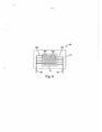
A figura 1 é uma vista superior de um aparelho de barbear ou depilar, de acordo com uma modalidade da presente invenção, com o cartucho separado do cabo. As figuras 1A e 1B são vistas em seção transversal do cabo do aparelho de barbear ou depilar da figura 1. A figura 2 é uma vista lateral parcial do cabo do aparelho de barbear ou depilar da figura 1 mostrando componentes do mesmo. A figura 3 é um diagrama de circuito de um sensor de remoção de cartucho. A figura 4 é uma vista inferior parcial da cabeça de um aparelho de barbear ou depilar da figura 1. As figuras 5 e 5A são vistas laterais parciais do cabo do aparelho de barbear ou depilar da figura 1 mostrando componentes existentes no mesmo. A figura 6 é uma vista explodida de um botão mostrando um sensor. A figura 7 mostra um controlador para determinação e indicação da capacidade remanescente de barbeamento ou depilação de um cartucho para barbeamento ou depilação. As figuras 8A e 8B mostram a saída de sinais pelos componentes de um indicador de vida útil de um cartucho. A figura 9 mostra uma modalidade do controlador da figura 6. A figura 10 mostra um método de determinação da capacidade remanescente de barbeamento ou depilação de um cartucho e indicação da capacidade de barbeamento ou depilação remanescente à um usuário.Figure 1 is a top view of a razor or shaver, according to an embodiment of the present invention, with the cartridge separated from the handle. Figures 1A and 1B are seen in cross section of the razor or shaver handle in figure 1. Figure 2 is a partial side view of the razor or shaver handle in figure 1 showing components thereof. Figure 3 is a circuit diagram of a cartridge removal sensor. Figure 4 is a partial bottom view of the head of a razor or shaver in Figure 1. Figures 5 and 5A are partial side views of the handle of the razor or shaver in Figure 1 showing components therein. Figure 6 is an exploded view of a button showing a sensor. Figure 7 shows a controller for determining and indicating the remaining shaving or waxing capacity of a shaving or waxing cartridge. Figures 8A and 8B show the output of signals by the components of a cartridge life indicator. Figure 9 shows a modality of the controller of figure 6. Figure 10 shows a method of determining the remaining shaving or waxing capacity of a cartridge and indicating the remaining shaving or waxing capacity to a user.
Com referência às figuras 1, IA, e 1B, um aparelho de barbear ou depilar 1 tem um cartucho 18 e um cabo 10 que inclui uma cabeça do aparelho de barbear ou depilar 12, um tubo de empunhadura 14, e uma carcaça de bateria 16. A cabeça do aparelho de barbear ou depilar 12 inclui uma estrutura de conexão 17 para conectar o cartucho 18 ao cabo 10 e um mecanismo de liberação 19 para liberar o cartucho 18 da estrutura de conexão 11. O tubo de empunhadura 14 é fabricado para ser segurado pelo usuário durante o barbeamento ou a depilação, e para conter os componentes do aparelho de barbear ou depilar que fornecem o recurso de £m«jiuiiamento por bateria (disposição elétrica) do aparelho de barbear ou depilar, por exemplo, um dispositivo elétrico 28, uma placa de circuito impresso ("PCB") 30, uma chave eletrônica 29 e a luz 31 instalados sobre a placa de circuito impresso. O dispositivo elétrico 28 pode ser um motor, um gerador de vibração, uma fonte de calor, uma bomba, um gerador de radiação, um gerador de campo magnético, um gerador de campo elétrico, um gerador de campo eletromagnético, uma fonte química, ou combinações dos mesmos podem ser substituídas por dispositivo elétrico de vibração 28.Referring to Figures 1, IA, and 1B, a shaver or
O tubo de empunhadura 14 inclui um botão atuador 22 que pode ser pressionado pelo usuário para acionar o recurso de funciomanento por bateria do aparelho para barbeamento ou depilação por meio de uma chave eletrônica 29. Em alguns exemplos, o tubo de empunhadura pode, também, incluir uma janela transparente 24 para permitir que o usuário veja uma luz 31, uma tela ou outro indicador visual, por exemplo um LED ou LCD, o qual forneça ao usuário uma indicação visual quanto ao estado da bateria e/ou outras informações. Conforme descrito até o presente momento, o cabo do aparelho de barbear ou depilar 10 é conhecido e descrito em maiores detalhes no Pedido de Patente da Requerente US n° 11/220,015, depositada em 10 de Abril de 2005, publicada como Publicação de Pedido de Patente US n° 2007/0050981. O aparelho de barbear ou depilar pode ser equipado com motor por várias fontes de energia, incluindo, mas não se limitando a, radiana, cinética, potencial, térmica, magnética, gravitacional, energia sonora, energia luminosa, eletromagnética, química, e combinações das mesmas.The
Com referência às figuras 1, 1A, e 2, um indicador 26 está disposto voltado para a extremidade frontal 20 do tubo de empunhadura 14 e inclui, em alguns exemplos, os LEDs 32 e 34 acoplados eletricamente ao controlador 40 através do PCB 33. Em outras modalidades, o indicador está situado em qualquer local sobre ou dentro do aparelho de barbear ou depilar. Podem ser usados outros indicadores, por exemplo, visuais, audíveis, olfativos, sensoriais, ou táteis. Embora o indicador 26 possa incluir duas fontes de luz de cores diferentes, poderiam ser usadas três ou mais fontes de luz. Em um exemplo, o LED 32 emite luz azul e o LED 34 emite luz branca, embora quaisquer duas cores poderiam ser usadas.With reference to figures 1, 1A, and 2, an
O indicador 26 inclui, ainda, um elemento misturador de luz 36 circundando os LEDs 32 e 34. Quando ambos os LEDs 32 e 34 emitem luzes de cores diferentes para indicar a capacidade remanescente de barbeamento ou depilação do cartucho 18, o elemento 36 mistura as duas cores e parece sinalizar uma cor, conforme descrito com mais detalhes abaixo. Em um exemplo, o elemento misturador de luz 3 6 é uma porção de pescoço transparente 3 8 que se estende ao redor da circunferência do tubo de empunhadura 14 e circundando completamente a extremidade 20. Em um exemplo adicional, o elemento misturador de luz 36 poderia ser qualquer porção do cabo 10 ou cartucho 18 configurada para misturar luz dos LEDs 32 e 34 como uma janela, lente, tubo de luz, ou alguma combinação dos mesmos, na porção do pescoço 38, tubo de empunhadura 14, ou cartucho 18. A porção de pescoço 38 é moldada, de preferência, a partir de um copolímero de acrílico transparente Zylar, disponível junto à Nova Chemicals Corp., Moon Township, PA, EUA embora possa ser formado a partir de qualquer material transparente ou translúcido.
A cabeça do aparelho de barbear ou depilar 12 inclui um mecanismo de liberação 19 que inclui um botão 50 que tem um elemento de base 52 com braços propulsores que se projetam adiante 56 para liberar o cartucho 18 da estrutura de conexão 17. Um elemento de preensão 54 está disposto sobre o elemento base 52 para empurrar o engate ao liberar o cartucho 18. Conforme descrito até o momento, o mecanismo de liberação do cartucho é conhecido e descrito com mais detalhes na Patente US n°. 7.197.825.The head of the razor or
Em alguns exemplos, a cabeça do aparelho de barbear ou depilar 12 inclui um sensor 60 acoplado eletricamente ao controlador 40 através de linhas 62 para detecção do momento de fixação/remoção do cartucho 18 à cabeça do aparelho de barbear ou depilar 12. Com referência às figuras 1, 2 e 4, em um exemplo, o sensor 60 pode incluir uma microchave 76 disposta na cabeça do aparelho de barbear ou depilar 12 e um elemento de pino 72 que se projeta de um botão 50 transversalmente à direção adiante 74. A microchave 7 6 pode ser uma chave normalmente fechada ou aberta que tem um elemento de alavanca frontalmente polarizado 78 e o sinal resultante é acoplado eletricamente AO controlador 40 por linhas 80. Quando o botão 50 está na posição posterior, o elemento de pino 72 impulsiona o elemento de alavanca 78 para trás e mantém a microchave 76 em um estado de "cartucho fixado11 (por exemplo, fechado por uma microchave normalmente fechada). quando o botão 50 é empurrado para frente na direção 74 para remoção do cartucho 18, a inclinação para frente do elemento de alavanca 78 altera o estado da microchave 76 para o estado "cartucho removido" (por exemplo, aberto por uma microchave normalmente fechada). Alternativamente, a microchave 7 6 pode ter um elemento de alavanca posteriormente polarizado 78 que é impulsionado para frente pelo elemento de pino 72 para alterar a chave do estado "cartucho fixado" para "cartucho removido".In some examples, the head of the razor or
Com referência às figuras 2 e 3, em um exemplo adicional, o sensor 60 pode incluir um PCB 64 instalado na cabeça do aparelho de barbear ou depilar 12 e que tem os eletrodos 66a e 66b no mesmo. Conforme se pode observar com mais detalhes na figura 3, os dedos 68a do eletrodo 66a são entrelaçados, mas não são eletricamente acoplados aos dedos 68b do eletrodo 66b. O elemento resistive 70 entra em contato eletricamente, mas não se acopla eletricamente aos dedos 68a e 68b do eletrodo. Em alguns exemplos, o elemento resistive 70 pode ser formado de um compósito de tunelamento quântico (QTC) de partículas metálicas condutivas finamente dispesas, como liga metálica ou partícula de óxido metálico reduzido, em um material de matriz não-condutivo, como um elastômero. Em QTC, as partículas de metal são dispersas próximas umas às outras mas não entram em contato para formar trajetos condutivos diretos através do compósito quando em estado de repouso. Quando sob pressão, entretanto, as partículas se movem suficientemente próximas para que se formem trajetórias altamente condutivas a partir do tunelamento quântico entre as partículas condutivas. Quando a pressão é removida, o QTC retorna ao seu estado de repouso não-condutivo. Em um exemplo, o elemento resistive pode ser uma porção de cerca de 4 mm por cerca de 2 mm de pílulas de QTC disponíveis junto à PeraTech Ltd. North Yorkshire, Inglaterra. À medida que o botão 50 é empurrado para frente para liberação do cartucho 18, o elemento de pino 72 aplica pressão ao elemento resistivo 70 alterando seu estado de não-condutivo para condutivo, acoplando-se eletricamente aos eletrodos 66a e 66b. Consequentemente, a mudança de tensão através dos eletrodos 66a e 66b pode ser detectada pelo controlador 40.Referring to figures 2 and 3, in a further example,
Em um exemplo adicional, o elemento resistivo 70 pode ser formado a partir de um polímero sensível à pressão que tem partículas condutivas (por exemplo, carbono) ou semicondutivas (por exemplo, silício) dispersas no mesmo. Em geral, o polímero sensível à pressão acopla eletricamente os eletrodos 66a e 66b e tem uma resistência base quando em estado de repouso, aumentando ou diminuindo a resistência em função da pressão aplicada ao mesmo. Em um outro exemplo, o elemento resistivo 70 é fabricado a partir de um polímero, partículas metálicas, um material semicondutivo, combinações dos mesmos, ou de outro material adequado ao propósito ao qual se destina.In a further example, the
Com referência às figuras 5 e 5A em um exemplo adicional, o sensor 60 pode incluir um elemento magnético 82 disposto sobre o botão 50 e uma chave magnética 84 acoplada eletricamente ao controlador 40 em um estado de "cartucho fixado" (por exemplo, fechado)(figura 5). À medida que o botão 50 é empurrado para frente ao longo da direção 74 para a liberação do cartucho 18, o campo magnético do elemento 82 altera a chave magnética 84 para o estado "cartucho removido" (por exemplo, aberta) (figura 5A) . Quando botão 50 é liberado e se move para trás, a chave magnética 84 retorna para o estado "cartucho fixado". Podem ser usadas outras chaves no lugar da chave magnética 84, por exemplo, uma chave de efeito Hall.Referring to figures 5 and 5A in an additional example,
Com referência à figura 6, em um exemplo adicional, o sensor 60 pode ser disposto sobre o elemento de base 52 do botão 50, o qual pode ser formado de um material relativamente rígido, como um polímero de acetila. Em outra modalidade, um elemento de preensão 54 cobre o botão 50. 0 elemento de preensão pode ser fabricado a partir de qualquer material adequado, por exemplo, material relativamente macio, elastômero, material rígido, ou combinações dos mesmos. O sensor 60 detectará a força aplicada ao elemento de preensão 54 para superar a força de inclinação da mola 58 (figura 1A) para trás e mover o botão 50 para frente para liberação do cartucho, bem como as possíveis forças adicionais durante a remoção do cartucho 18 e nivelar o curso do botão 50.With reference to figure 6, in a further example, the
Em um exemplo, o sensor 60 pode ser um resistor sensível à pressão 90 acoplado eletricamente ao controlador 40 por linhas 92 que alteram a resistência de forma proporcional à força aplicada à porção ativa 94 disposta sob a porção de preensão 54. Um resistor sensível à pressão 90 adequado é um resistor sensível à pressão Interlink FSR400, disponível junto à Interlink Electronics Inc., de Camarillo, CA, EUA. Em outro exemplo, o sensor 60 pode incluir um elemento resistivo QTC e eletrodos similares aos descritos anteriormente.In one example,
Em um outro exemplo, o sensor pode ser do tipo selecionado a partir de condutivo, capacitivo, magnético, resistivo, de proximidade, sensível à pressão, químico, indutivo, elétrico, mecânico, eletromecânico, eletromagnético, e combinações dos mesmos. Outro sensor adequado para os propósitos ao qual se destina também poderia ser usado. Em alguns exemplos, o sensor é conversível entre o primeiro nível e o segundo nível em resposta à ação que está sendo aplicada. 0 sensor pode ser convertido do segundo nível para o primeiro nível em resposta à ação de remoção.In another example, the sensor can be of the type selected from conductive, capacitive, magnetic, resistive, proximity, pressure sensitive, chemical, inductive, electrical, mechanical, electromechanical, electromagnetic, and combinations thereof. Another sensor suitable for its intended purpose could also be used. In some examples, the sensor is convertible between the first level and the second level in response to the action being applied. The sensor can be converted from the second level to the first level in response to the removal action.
Os novos cartuchos de barbear ou depilar têm uma quantidade finita de vida útil estimada, uso, ou capacidade ("capacidade estimada") , incluindo, mas não se limitando a, corte, lubrificação, limpeza, ou outros tipos de deterioração. As lâminas eventualmente cegam e o desempenho de barbeamento ou depilação deteriora a um ponto tal que o cartucho deve ser substituído. Embora a capacidade estimada possa variar de usuário para usuário por diversas razões, podem ser feitas suposições acerca da capacidade estimada após a qual um cartucho deve ser substituído e testes realizados com o consumidor podem fornecer dados para maximização da capacidade estimada em uma ampla gama de usuários. Mesmo que um usuário individual apresente uma capacidade estimada do que se presume, saber a diferença entre a capacidade estimada e a real capacidade do usuário (isto é, "capacidade remanescente de barbeamento ou depilação") pode orientar o usuário a decidir quando substituir um cartucho.New shaving or shaving cartridges have a finite amount of estimated service life, usage, or capacity ("estimated capacity"), including, but not limited to, cutting, lubricating, cleaning, or other types of deterioration. The blades eventually blind and the shaving or shaving performance deteriorates to such an extent that the cartridge must be replaced. Although the estimated capacity may vary from user to user for several reasons, assumptions can be made about the estimated capacity after which a cartridge must be replaced and tests carried out with the consumer can provide data to maximize the estimated capacity for a wide range of users . Even if an individual user has an estimated capacity than is assumed, knowing the difference between the estimated capacity and the user's actual capacity (ie, "remaining shaving or waxing capacity") can guide the user in deciding when to replace a cartridge .
Com referência à figura 7, em alguns exemplos, o aparelho de barbear ou depilar 1 inclui sistema de detecção da vida útil do cartucho 100 para rastreamento da capacidade de barbeamento ou depilação do cartucho 18 e indicação da sua vida útil remanescente. O controlador 40 recebe os dados da fonte de dados 102 quando o usuário está se barbeando ou depilando. Em alguns exemplos, a entrada pode ser a ativação do dispositivo elétrico 28 pela chave de acionamento 22. Em outro exemplo, a entrada poderia ser a hora em que o dispositivo elétrico 28 é ativado. Em ainda outro exemplo, a entrada poderia ser instâncias de tempo gastos pelo contato entre a pele do usuário e o cartucho 18. Um método de detecção do contato com a pele é detalhado no Pedido de Patente US n° de série 11/799,843. Em um exemplo adicional, a entrada poderia ser instâncias de tempo acumulado de movimento detectado entre o cartucho 18 e o cabo 10 ou da preensão do cabo 10 detectada pelo usuário. Em outro exemplo, uma ou mais das entrada anteriores poderiam ser combinadas para determinar quando a usuário está se barbeando ou depilando e o cartucho 18 está sendo usado.Referring to Figure 7, in some examples, the razor or
O detector de barbeamento ou depilação 104 determina se a entrada da fonte de entrada 102 deveria ser contada e filtra as entradas inadvertidas. Em um exemplo, o detector de barbeamento ou depilação 104 calcula o tempo em que o dispositivo elétrico 28 permanece ativo. Após um período de tempo, como 15 segundos, por exemplo, é provável que esteja ocorrendo o barbeamento ou depilação e o detector de barbeamento ou depilação 104 permite que a entrada da fonte 102 seja contada. Em alguns exemplos, o controlador 40 inclui um temporizador de travamento 106 que faz a contagem regressiva do período de tempo durante o qual os dados de barbeamento ou depilação não são contados. Por exemplo, um usuário pode, momentaneamente, desligar o dispositivo elétrico 28 durante o uso, ou a chave 22 pode ser inadvertidamente pressionada quando o aparelho de barbear ou depilar 1 é armazenado no intervalo entre as utilizações. 0 tratamento dessas entradas como "barbeamentos ou depilações"separados e distintos que reduzem a capacidade remanescente de barbeamento ou depilação de um cartucho tornaria o sistema 100 menos preciso. Em um exemplo, o temporizador de travamento 106 despreza os dados do detector de barbeamento ou depilação 104 por quatro horas após a ativação do dispositivo elétrico 28.Shaving or shaving
O contador de barbeamentos ou depilações 108 recebe e rastreia a entrada de barbeamentos ou depilações recebidas pelo detector de barbeamento ou depilação 104, armazenando a entrada acumulada de barbeamentos ou depilações (isto é, a capacidade real) na memória 110, enquanto que o sensor 60 se mantém no estado "cartucho fixado". O contador de barbeamentos ou depilações 108 compara a entrada rastreada de barbeamentos ou depilações com a capacidade estimada de barbeamento ou depilação, armazenada na memória 110, por exemplo, e determina a capacidade remanescente de barbeamento ou depilação do cartucho 18. Em um exemplo, o contador 108 compara o número de ativações do dispositivo elétrico 28, filtradas pelo detector de barbeamento ou depilação 104, e trava o temporizador 106, conforme descrito acima, e o compara com o número estimado de ativações. Em alguns exemplos, o número estimado de ativações é maior que cerca de 8, entre cerca de 8 e cerca de 20, e cerca de 14.The shave or
O controlador 40 apaga do contador 108 os dados acumulados de barbeamento ou depilação, bem como a memória 110, quando o sensor 60 está no estado "cartucho removido". Em alguns exemplos, o estado removido do cartucho pode ser o fechamento de um circuito, como pelo fechamento de uma microchave 76 ou de um interruptor de lâminas 84 ou pela aplicação de pressão a um elemento resistivo 70 formado de QTC. Em um outro exemplo, o estado removido do cartucho pode ser a abertura de um circuito, como pela abertura de uma microchave 76 ou interruptor de lâminas 84. Em um exemplo adicional, o estado removido do cartucho pode ser uma tensão através do elemento resistivo 70 formado por um polímero sensível à pressão ou através de um resistor sensível à pressão 90 que excede um valor-limite. Em outro exemplo, o estado de cartucho removi do pode ser obtido pela depressão contínua da chave elétrica por ao menos 1 segundo.
Embora a capacidade estimada de barbeamento ou depilação possa ser programada no controlador 40 durante a fabricação, não há necessidade de ser um valor fixo. Em alguns exemplos, o sistema 100 poderia ser configurado para permitir ao usuário ajustar a capacidade estimada de barbeamento ou depilação. Em um exemplo adicional, o sistema 100 poderia ajustar automaticamente a capacidade estimada de barbeamento ou depilação com base no histórico do usuário de utilizações por cartucho. Por exemplo, o contador de barbeamentos ou depilações 108 poderia recordar o número de ativações do dispositivo elétrico 28 dos cinco cartuchos anteriores e ajustar a capacidade estimada de barbeamento ou depilação para o próximo cartucho pela capacidade média dos cinco anteriores.Although the estimated shaving or waxing capacity can be programmed into the
Com referência às figuras 7, 8A, e 8B, em alguns exemplos, o controlador 40 indica a capacidade de barbeamento ou depilação remanescente do cartucho 18 com luz de saída 113 emitida pelos LEDs 32 e 34 e misturados no elemento misturador de luz 36. Preferencialmente, os LEDs 32 e 34 emitem luz colorida contrastante, como azul e branco, por exemplo. O modulador de largura de pulso gera sinais 114 e 116 para iluminar os LEDs 32 e 34, respectivamente, a níveis de tensão alta e baixa. Quando os pulsos de sinal (isto é, tensão mais alta) são relativamente longos em relação ao tempo entre os pulsos (isto é, tensão mais baixa), como o sinal 114, o LED emite uma luz relativamente clara. Inversamentc, quando os pulsos são x*elaLlvamexite curtos em relação ao tempo entre os mesmos (por exemplo, o sinal 116), o LED emite uma luz relativamente fraca.With reference to figures 7, 8A, and 8B, in some examples,
Ao misturar duas luzes de cores contrastantes e brilho variável, o sistema 100 é capaz de comunicar uma ampla e gradual faixa de luz de saída colorida 113 representando a vida útil remanescente do cartucho para o usuário com poucos elementos luminosos e baixo consumo de energia. Em alguns exemplos, a cor do LED 32 representa a capacidade de barbeamento ou depilação remanescente, com o brilho total representando a capacidade remanescente total de barbeamento ou depilação (isto é, capacidade estimada) . A cor do LED 34 representa a ausência de capacidade de barbeamento ou depilação remanescente, com o brilho total representando nenhuma capacidade de barbeamento ou depilação remanescente e que o cartucho deve ser substituído. Por exemplo, o envio do sinal 114 ao LED azul 32 (isto é, produção de uma luz azul brilhante) e do sinal 116 ao LED branco 34 (isto é, produção de uma luz branco pálido) resulta em um elemento misturador de cores 3 6 que emite uma luz de saída relativamente azul escuro 113, indicando maior capacidade remanescente de barbeamento ou depilação. 0 envio do sinal 118 a um LED azul 32 (isto é, produção de uma luz azul pálida) e do sinal 120 a 10 um LED branco 34 (isto é, produção de uma luz branco brilhante) resulta em um elemento 36 que emite uma luz de saída relativamente azul pálido 113, indicando menor capacidade remanescente de barbeamento ou depilação. As duas luzes podem ser misturadas de forma que a luz de saída 113 1 s mantenha um brilho constante ou varie de brilho em toda a gama de saída de luz colorida. As duas luzes podem ser alteradas proporcionalmente à capacidade remanescente de barbeamento ou depilação ou não (por exemplo, exponencialmente). Cada luz pode ser alterada dependente ou independentemente uma da outra. Em outros exemplos, poderia ser usado fonte de luz no lugar de LED. Em um exemplo adicional, poderiam ser usadas mais de duas fontes de luz. A mistura aditiva de luzes de três cores primárias poderia ser usada para gerar toda a faixa de cores visíveis, por exemplo.By mixing two lights of contrasting colors and variable brightness, the
Com referência à figura 9, a configuração do controlador 40 pode ser implementada em um sistema programável em um chip, como CY8C21634, disponível junto à Cupress Semiconductor Corp., de San Jose, CA, EUA. 0 controlador 40 inclui um microcontrolador Ul. A bomba chaveada (SMP) integrada, em conjunto com Ll, D4 e C2 aumenta a carga de uma bateria alcalina de 1,4 V acoplada por VBATT para 3,3 V (VCC). O aparelho de barbear ou depilar 1 é ligado pela chave 22 (SW1) que tem um resistor pull up fraco RI. O microcontrolador Ul detecta a ativação da chave 22 através de uma entrada/saída de uso geral (GPIO). O microcontrolador Ul liga e desliga o dispositivo elétrico 28 através do transístor Q1. D3 é usado para proteger o controlador 40 da força contra-eletromotriz do dispositivo elétrico 28. O microcontrolador Ul liga diretamente os LEDs 32 e 34 através de pequenos resistores limitadores de corrente R2 e R3. Como discutido anteriormente, o controlador 40 controla a luminosidade dos LEDs 32 e 34 através da modulação da largura de pulso (PWM) . A saída para o LED32 (pino P2L1J) é também alimentada de volta ao microcontrolador Ul para criar o PWM inverso para a saída do LED 34 saída (pino P0 [6]). A luz indicadora de bateria baixa 31 é fornecida pelo LED vermelho(D2) e seu resistor limitador de corrente R5. O microcontrolador Ul pode detectar a remoção do cartucho 18 através do sensor de remoção do cartucho 60 usando um separador potencial formado por R6. O microcontrolador Ul monitora essa atividade usando outro GPIO (pino P0[l]). O capacitor C4 fornece filtragem do sinal a partir do sensor de remoção do cartucho 60. Certamente o controlador 40 poderia ser implementado de outras formas, como pelo uso de componentes distintos (por exemplo, transístores, diodos, resistores, e capacitores) ou ASIC customizado (circuito Integrado para executar uma tarefa específica), configurado para as funcionalidades aqui descritas.With reference to figure 9, the configuration of
Com referência à figura 10, em alguns exemplos, um método 200 de controle do aparelho de barbear ou depilar 1 inicia-se com o aparelho de barbear ou depilar 1 sendo acionado na etapa 202 quando um usuário pressiona a chave 22. O dispositivo elétrico 28, por exemplo, motor, é iniciado na etapa 204 e a modulação da largura de pulso de um LED azul 32 e um LED branco 34 começa (206, 208) para fazer o aparelho de barbear ou depilar 1 entrar no modo "funcionamento" na etapa 210. Se o aparelho de barbear ou depilar 1 está no modo funcionamento por mais de 15 segundos (212) e mais de quatro horas se passaram desde o último acionamento do aparelho de barbear ou depilar (214) , então o aparelho de barbear ou depilar 1 acumulou uma capacidade de barbeamento ou depilação. Consequentemente, as larguras de pulso para LED azul 32 são progressivamente diminuídas, LED ligeiramente pálido 32 (216) e as larguras de pulso para LED branco 34 são incrementalmente aumentadas (218), LED ligeiramente brilhoso 34. Isso resulta em uma luz de saída colorida azul ligeiramente desvanecida 113 emitida pelo elemento misturador de luz 36. A medida que maiores capacidades de barbeamento ou depilação são acumuladas, a luz de saída 113 eventualmente torna-se totalmente branca, e nesse momento o cartucho 18 deve ser substituído.Referring to figure 10, in some examples, a
Enquanto no modo funcionamento, se a chave 22 é acionada na etapa 220, o aparelho de barbear ou depilar 1 entra no modo desligado na etapa 222, no qual o motor (224) e os LEDs 32 e 34 (226, 228) são bloqueados, e, então, entra no modo inativo na etapa 230. No modo inativo, a chave 22 e o sensor 60 são monitorados (232, 234). Se o cartucho 18 é removido, a modulação da largura de pulso 5 para o LED azul 32 é definida em 100% na etapa 23 6 e a modulação para o LED branco 34 é definida para modulação 0% na etapa 238. Se a chave 22 é atuada durante o modo inativo na etapa 232, o aparelho de barbear ou depilar 1 entra novamente no modo ligado na etapa 202.While in operating mode, if
As dimensões e valores apresentados na presente invenção não devem ser compreendidos como estando estritamente limitados aos exatos valores numéricos mencionados. Em vez disso, exceto onde especificado em contrário, cada uma dessas dimensões se destina a significar Lauto o valor declarado como uma faixa de valores funcionalmente equivalentes em torno daquele valor. Por exemplo, uma dimensão apresentada como "40 mm" destina- se a significar "cerca de 40 mm".The dimensions and values presented in the present invention should not be understood as being strictly limited to the exact numerical values mentioned. Instead, unless otherwise specified, each of these dimensions is intended to mean Lauto the declared value as a range of functionally equivalent values around that value. For example, a dimension shown as "40 mm" is intended to mean "about 40 mm".
Cada um dos documentos citados na presente 20 invenção, inclusive qualquer referência remissiva, patente ou pedido de patente relacionado, está aqui incorporado na íntegra, a título de referência, a menos que seja expressamente excluído ou, de outro modo, limitado. A citação de qualquer documento não é uma admissão de que o 25 mesmo seja técnica anterior em relação a qualquer invenção apresentada ou reivindicada no presente documento, ou de que o mesmo, por si só ou em qualquer combinação com qualquer outra referência ou referências, ensine, sugira ou apresente qualquer invenção como essa. Além disso, se houver conflito entre qualquer significado ou definição de um termo mencionado neste documento e qualquer significado ou definição do mesmo termo em um documento incorporado a 5 título de referência, terá precedência o significado ou definição atribuído ao dito termo neste documento.Each of the documents cited in the present invention, including any referenced reference, patent or related patent application, is hereby incorporated in its entirety, by way of reference, unless expressly excluded or otherwise limited. The citation of any document is not an admission that the same 25 is prior art in relation to any invention presented or claimed in this document, or that it, alone or in any combination with any other reference or references, teaches , suggest or present any invention like this. In addition, if there is a conflict between any meaning or definition of a term mentioned in this document and any meaning or definition of the same term in a document incorporated as a reference title, the meaning or definition assigned to that term in this document will take precedence.
Embora modalidades específicas da presente invenção tenham sido ilustradas e descritas, deve ficar óbvio aos versados na técnica que várias outras alterações e 10 modificações podem ser feitas sem que se desvie do caráter e âmbito da invenção. Portanto, pretende-se cobrir nas reivindicações anexas todas essas alterações e modificações que se enquadram no escopo da presente invenção.Although specific embodiments of the present invention have been illustrated and described, it should be obvious to those skilled in the art that various other changes and modifications can be made without departing from the character and scope of the invention. Therefore, it is intended to cover in the appended claims all such changes and modifications that fall within the scope of the present invention.
Claims (7)
Priority Applications (1)
| Application Number | Priority Date | Filing Date | Title |
|---|---|---|---|
| BR122019025496-6A BR122019025496B1 (en) | 2007-09-17 | 2008-09-17 | safety device for shaving or shaving |
Applications Claiming Priority (5)
| Application Number | Priority Date | Filing Date | Title |
|---|---|---|---|
| US99407507P | 2007-09-17 | 2007-09-17 | |
| US994,075 | 2007-09-17 | ||
| US208,544 | 2008-09-11 | ||
| US12/208,544 US8230600B2 (en) | 2007-09-17 | 2008-09-11 | Cartridge detachment sensor |
| PCT/IB2008/053772 WO2009037652A2 (en) | 2007-09-17 | 2008-09-17 | Cartridge detachment sensor |
Publications (2)
| Publication Number | Publication Date |
|---|---|
| BRPI0816984A2 BRPI0816984A2 (en) | 2015-03-24 |
| BRPI0816984B1 true BRPI0816984B1 (en) | 2020-07-14 |
Family
ID=40452960
Family Applications (2)
| Application Number | Title | Priority Date | Filing Date |
|---|---|---|---|
| BRPI0816984-5A BRPI0816984B1 (en) | 2007-09-17 | 2008-09-17 | SAFETY APPLIANCE FOR SHAVING OR STYLING |
| BR122019025496-6A BR122019025496B1 (en) | 2007-09-17 | 2008-09-17 | safety device for shaving or shaving |
Family Applications After (1)
| Application Number | Title | Priority Date | Filing Date |
|---|---|---|---|
| BR122019025496-6A BR122019025496B1 (en) | 2007-09-17 | 2008-09-17 | safety device for shaving or shaving |
Country Status (13)
| Country | Link |
|---|---|
| US (2) | US8230600B2 (en) |
| EP (1) | EP2197635B2 (en) |
| JP (1) | JP2010538693A (en) |
| KR (1) | KR20100043284A (en) |
| CN (1) | CN101801621B (en) |
| AU (1) | AU2008300241A1 (en) |
| BR (2) | BRPI0816984B1 (en) |
| CA (1) | CA2698439A1 (en) |
| MX (1) | MX2010002953A (en) |
| PL (1) | PL2197635T3 (en) |
| RU (1) | RU2451596C2 (en) |
| TW (1) | TW200932458A (en) |
| WO (1) | WO2009037652A2 (en) |
Families Citing this family (61)
| Publication number | Priority date | Publication date | Assignee | Title |
|---|---|---|---|---|
| US8061041B2 (en) * | 2007-02-14 | 2011-11-22 | The Gillette Company | Safety razor |
| CN101676052B (en) * | 2008-09-19 | 2013-10-30 | 德昌电机(深圳)有限公司 | Electric drill with force sensing device |
| RU2486050C2 (en) * | 2008-10-01 | 2013-06-27 | Бик-Вайолекс Са | Razor set handle detachably connected to cartridge and razor set having such handle |
| JP6098117B2 (en) * | 2012-10-31 | 2017-03-22 | 日立工機株式会社 | Portable tools |
| US10441307B2 (en) | 2013-09-09 | 2019-10-15 | Dd Karma Llc | Hand held dermaplaning device and dermaplaning process |
| JP2016533847A (en) | 2013-09-09 | 2016-11-04 | リービ、ダーラ | Portable skin peeling device and skin peeling process |
| US9144912B2 (en) * | 2013-10-02 | 2015-09-29 | Brett Marut | Shaving apparatus |
| US9919437B2 (en) * | 2013-11-05 | 2018-03-20 | Koninklijke Philips N.V. | Personal care device |
| US20170305023A9 (en) * | 2013-11-27 | 2017-10-26 | Lamar Ball | Shaving systems with razor blade usage tracking |
| US9707690B2 (en) | 2013-12-20 | 2017-07-18 | The Gillette Company Llc | Heated shaving razor handle |
| US9751229B2 (en) | 2013-12-20 | 2017-09-05 | The Gillette Company Llc | Heated shaving razor |
| US9469039B2 (en) | 2014-01-14 | 2016-10-18 | The Gillette Company | Heated shaving razors |
| US9751228B2 (en) | 2014-01-14 | 2017-09-05 | The Gillette Company Llc | Shaving cartridges having thermal sensors |
| US9592615B1 (en) * | 2014-01-31 | 2017-03-14 | Karen Broeske | Lighted razor systems |
| CN106457583B (en) * | 2014-03-05 | 2019-04-12 | 麦凯瑞公司 | Double-sided razor |
| CN106103018B (en) * | 2014-03-14 | 2018-11-20 | 皇家飞利浦有限公司 | Electric shaver |
| EP3204198B1 (en) | 2014-10-10 | 2020-09-30 | Edgewell Personal Care Brands, LLC | Universal razor cartridge handle |
| WO2016094327A1 (en) * | 2014-12-10 | 2016-06-16 | Haggai Goldfarb | Intelligent shaving system having sensors |
| US11007659B2 (en) * | 2014-12-10 | 2021-05-18 | Haggai Goldfarb | Intelligent shaving system having sensors |
| US10298471B2 (en) | 2015-10-05 | 2019-05-21 | The Gillette Company Llc | Systems and methods for providing device usage data |
| EP3984478A1 (en) * | 2015-12-21 | 2022-04-20 | DD Karma LLC | Hand held dermaplaning device |
| USD795497S1 (en) | 2016-01-15 | 2017-08-22 | Medline Industries, Inc. | Clipper |
| USD794871S1 (en) | 2016-01-15 | 2017-08-15 | Medline Industries, Inc. | Clipper |
| EP3219451B1 (en) * | 2016-03-14 | 2019-11-13 | The Gillette Company LLC | Method of assembling an electronic subassembly for a personal care product |
| USD802214S1 (en) | 2016-06-10 | 2017-11-07 | Medline Industries, Inc. | Clipper head |
| USD802216S1 (en) | 2016-06-10 | 2017-11-07 | Medline Industries, Inc. | Clipper head |
| USD802217S1 (en) | 2016-06-10 | 2017-11-07 | Medline Industries, Inc. | Clipper head |
| USD802215S1 (en) | 2016-06-10 | 2017-11-07 | Medline Industries, Inc. | Clipper head |
| US10652956B2 (en) | 2016-06-22 | 2020-05-12 | The Gillette Company Llc | Personal consumer product with thermal control circuitry and methods thereof |
| CN108237566A (en) * | 2016-12-23 | 2018-07-03 | 阿尔卡特朗讯 | Razor |
| EP3351358B1 (en) | 2017-01-20 | 2019-11-20 | The Gillette Company LLC | Heating delivery element for a shaving razor |
| EP3644784A1 (en) | 2017-06-29 | 2020-05-06 | BIC Violex S.A. | Smart dispenser system and methods of use. |
| US11504866B2 (en) * | 2017-06-29 | 2022-11-22 | BIC Violex Single Member S.A. | Shaver and methods for detecting shaving characteristics |
| EP3645225B1 (en) * | 2017-06-29 | 2021-08-04 | BIC Violex S.A. | System and method for electrically sensing shaving razor blade wear |
| EP3450120B1 (en) | 2017-08-30 | 2021-12-15 | Braun GmbH | Personal care device |
| JP7235746B2 (en) * | 2017-11-28 | 2023-03-08 | エッジウェル パーソナル ケア ブランズ リミテッド ライアビリティ カンパニー | razor handle |
| US10960560B2 (en) | 2018-01-19 | 2021-03-30 | The Gillette Company Llc | Method for generating user feedback information from a shave event |
| US10647011B2 (en) | 2018-01-19 | 2020-05-12 | The Gillette Company Llc | Networked shaving appliance system |
| US20190224869A1 (en) | 2018-01-19 | 2019-07-25 | The Gillette Company Llc | Shaving appliance including a notification circuit for communicating cumulative shave event information |
| US20190224867A1 (en) | 2018-01-19 | 2019-07-25 | The Gillette Company Llc | Method for generating user feedback information from a shave event and user profile data |
| EP3546150B1 (en) * | 2018-03-27 | 2021-10-27 | Braun GmbH | Personal care device |
| US11607820B2 (en) | 2018-03-30 | 2023-03-21 | The Gillette Company Llc | Razor handle with movable members |
| AU2019242730A1 (en) | 2018-03-30 | 2020-09-24 | The Gillette Company Llc | Razor handle with movable members |
| EP3546156B1 (en) | 2018-03-30 | 2021-03-10 | The Gillette Company LLC | Razor handle with a pivoting portion |
| WO2019191163A1 (en) | 2018-03-30 | 2019-10-03 | The Gillette Company Llc | Razor handle with a pivoting portion |
| BR112020020123A2 (en) | 2018-03-30 | 2021-01-26 | The Gillette Company Llc | shaver or shaving handle with a pivoting portion |
| CN111801201B (en) | 2018-03-30 | 2022-06-03 | 吉列有限责任公司 | Razor cartridge |
| USD874061S1 (en) | 2018-03-30 | 2020-01-28 | The Gillette Company Llc | Shaving razor cartridge |
| CN111819046B (en) | 2018-03-30 | 2022-09-13 | 吉列有限责任公司 | Razor handle with movable member |
| JP2021517043A (en) | 2018-03-30 | 2021-07-15 | ザ ジレット カンパニー リミテッド ライアビリティ カンパニーThe Gillette Company Llc | Razor handle with pivot part |
| BR112020020132A2 (en) | 2018-03-30 | 2021-01-05 | The Gillette Company Llc | HANDLE OF SHAVING OR DEVILING APPLIANCE WITH MOBILE LIMBS |
| WO2019191345A1 (en) | 2018-03-30 | 2019-10-03 | The Gillette Company Llc | Razor handle with a pivoting portion |
| CN112912216B (en) * | 2018-10-19 | 2023-03-10 | 吉列有限责任公司 | Carding device |
| US11273561B2 (en) * | 2019-05-30 | 2022-03-15 | Heated Blades Holding Company, Llc | Razor with heated and vibrating blades |
| US20210298449A1 (en) * | 2020-03-27 | 2021-09-30 | Shad E. Bruce | Personal Hygiene Apparatus and Method |
| US20230286183A1 (en) * | 2021-02-22 | 2023-09-14 | Benjamin Avery | Easy-Rinsing Razor Cartridge |
| US11881856B2 (en) | 2021-04-07 | 2024-01-23 | The Gillette Company Llc | Method of resetting a digital counter for a personal care appliance |
| US11389980B1 (en) * | 2021-04-07 | 2022-07-19 | The Gillette Company Llc | Personal care appliance |
| US11725811B2 (en) * | 2021-10-01 | 2023-08-15 | The Gillette Company Llc | Consumer appliance |
| US11794365B2 (en) * | 2021-10-01 | 2023-10-24 | The Gillette Company Llc | Personal care appliance |
| US11883971B2 (en) | 2022-03-23 | 2024-01-30 | The Gillette Company Llc | Electronic personal care device |
Family Cites Families (54)
| Publication number | Priority date | Publication date | Assignee | Title |
|---|---|---|---|---|
| US3229659A (en) * | 1964-09-22 | 1966-01-18 | Peter D Sciascia | Razor blade shave indicator |
| AT366946B (en) * | 1980-04-03 | 1982-05-25 | Payer Lux Elektroprod | ELECTRIC SHAVER |
| US4924995A (en) | 1989-09-29 | 1990-05-15 | Otis Elevator Company | Escalator handrail obstruction device with sensors |
| US5299354A (en) * | 1990-10-11 | 1994-04-05 | The Gillette Company | Oscillating shaver |
| AT403958B (en) * | 1992-02-17 | 1998-07-27 | Payer Lux Elektroprod | ELECTRIC SHAVER |
| US5347715A (en) * | 1993-09-14 | 1994-09-20 | Friedland Donald H | Blade shave counter |
| ES2122598T3 (en) * | 1994-06-01 | 1998-12-16 | Koninkl Philips Electronics Nv | SHAVING MACHINE WITH ADJUSTABLE SPEED MOTOR. |
| US6944952B1 (en) | 1994-07-01 | 2005-09-20 | The Gillette Company | Shaving system |
| FR2726925B1 (en) | 1994-11-10 | 1997-01-24 | Bonnet Laurent | COUNTER FOR THE USE OF BLADES ON A HAND RAZOR |
| US5794342A (en) * | 1996-08-09 | 1998-08-18 | Davey; Melville G. | Oscillating blade razor |
| CA2278246C (en) | 1997-01-25 | 2007-04-03 | Peratech Limited | Polymer composition |
| EP0864402B1 (en) * | 1997-03-13 | 2002-01-30 | Wella Aktiengesellschaft | Process and device for detecting oil shortage of an electrically driven cutting knife of a hair cutting machine |
| JPH1147463A (en) * | 1997-08-04 | 1999-02-23 | Izumi Prod Co | Electric razor |
| US6009623A (en) | 1997-10-02 | 2000-01-04 | Warner-Lambert Company | Razor with in situ sensor |
| CA2318742A1 (en) | 1998-01-23 | 1999-07-29 | Peratech Ltd. | Polymer composition |
| US6460251B1 (en) | 1998-03-25 | 2002-10-08 | Pfizer Inc. | Razor system with worn blade indicator |
| ATE268049T1 (en) | 1999-06-22 | 2004-06-15 | Peratech Ltd | STRUCTURES WITH CHANGING CONDUCTIVE VALUE |
| US6275137B1 (en) * | 2000-02-08 | 2001-08-14 | Boston Microsystems, Inc. | Semiconductor piezoresistor |
| GB0011829D0 (en) | 2000-05-18 | 2000-07-05 | Lussey David | Flexible switching devices |
| EP1162505A1 (en) * | 2000-06-07 | 2001-12-12 | SAN MARCO IMAGING s.r.l. | Photographic processing chemical supplier |
| WO2002064056A1 (en) * | 2001-02-12 | 2002-08-22 | Koninklijke Philips Electronics N.V. | Sonic power toothbrush with multiple containers |
| US6689970B2 (en) | 2001-10-04 | 2004-02-10 | Lester E. Burgess | Pressure actuated switching device and method and system for making same |
| GB2398534B (en) * | 2003-02-19 | 2005-11-16 | Gillette Co | Safety razors |
| GB0303872D0 (en) * | 2003-02-19 | 2003-03-26 | Gillette Co | Hand held appliances |
| GB2399045B (en) * | 2003-02-19 | 2005-11-16 | Gillette Co | Safety razors |
| US7654003B2 (en) | 2003-02-19 | 2010-02-02 | The Gillette Company | Safety razors with charge indicator and power switch |
| GB2406537B (en) | 2003-07-21 | 2006-09-06 | Gillette Co | Safety razors |
| GB0322057D0 (en) | 2003-09-20 | 2003-10-22 | Lussey David | Variable conductance materials |
| US20050110766A1 (en) | 2003-11-24 | 2005-05-26 | Elo Touchsystems, Inc. | Touch sensor with conductive polymer switches |
| US7119500B2 (en) | 2003-12-05 | 2006-10-10 | Dialight Corporation | Dynamic color mixing LED device |
| US7197825B2 (en) | 2004-03-11 | 2007-04-03 | The Gillette Company | Razors and shaving cartridges with guard |
| US7113179B2 (en) * | 2004-06-23 | 2006-09-26 | Interlink Electronics, Inc. | Force sensing resistor with calibration element and method of manufacturing same |
| US20060026841A1 (en) | 2004-08-09 | 2006-02-09 | Dirk Freund | Razors |
| US7317392B2 (en) | 2004-09-29 | 2008-01-08 | Methode Electronics, Inc. | Apparatus for occupant detection |
| US7100283B1 (en) | 2004-10-18 | 2006-09-05 | Greg Grdodian | Shaving system |
| FR2879347A1 (en) | 2004-12-14 | 2006-06-16 | Commissariat Energie Atomique | ELECTRONIC DEVICE COMPRISING TWO COMPONENTS AND METHOD FOR MANUFACTURING SUCH A DEVICE |
| US20060139025A1 (en) * | 2004-12-24 | 2006-06-29 | Mednovus, Inc. | Saturation-resistant magnetoresistive sensor for ferromagnetic screening |
| US20070050981A1 (en) * | 2005-09-06 | 2007-03-08 | Dirk Freund | Powered wet-shaving razor |
| US7367126B2 (en) * | 2005-09-06 | 2008-05-06 | The Gillette Company | Powered wet-shaving razor |
| DE102005045713A1 (en) * | 2005-09-24 | 2007-03-29 | Braun Gmbh | Electric hair removal device |
| DE102006004675A1 (en) * | 2006-02-02 | 2007-08-09 | Braun Gmbh | Electric razor |
| US20100064520A1 (en) * | 2006-05-05 | 2010-03-18 | Park Sung K | Modular grooming tool with dual motors |
| JP4697079B2 (en) * | 2006-07-20 | 2011-06-08 | パナソニック電工株式会社 | Shaver |
| US7788810B2 (en) * | 2006-07-24 | 2010-09-07 | Eveready Battery Company, Inc. | Shaving system having an umbilical |
| EP2073962B1 (en) | 2006-09-01 | 2011-05-11 | Eveready Battery Company, Inc. | Integrated shave counter and base |
| US20080052911A1 (en) * | 2006-09-01 | 2008-03-06 | Eveready Battery Company, Inc. | Shaving implement and method for using same |
| JP5568206B2 (en) * | 2006-09-15 | 2014-08-06 | 東海ゴム工業株式会社 | Deformation sensor |
| US8061041B2 (en) | 2007-02-14 | 2011-11-22 | The Gillette Company | Safety razor |
| DE602007010987D1 (en) * | 2007-04-26 | 2011-01-13 | Valeo Trading And Invest 3 Pty Ltd | SHAVER |
| US20090000124A1 (en) * | 2007-06-29 | 2009-01-01 | Eveready Battery Company, Inc. | Grooming tool assembly |
| US20090119923A1 (en) * | 2007-09-17 | 2009-05-14 | Robert Anthony Hart | Sensor For A Razor |
| US8122606B2 (en) * | 2007-09-17 | 2012-02-28 | The Gillette Company | Cartridge life indicator |
| US20100031510A1 (en) * | 2008-08-06 | 2010-02-11 | Matthias Gester | Heated shaving razor |
| ES2400208T3 (en) * | 2008-08-18 | 2013-04-08 | The Gillette Company | Combination shaver and trimmer device |
-
2008
- 2008-09-11 US US12/208,544 patent/US8230600B2/en active Active
- 2008-09-17 BR BRPI0816984-5A patent/BRPI0816984B1/en not_active IP Right Cessation
- 2008-09-17 KR KR1020107005835A patent/KR20100043284A/en not_active Application Discontinuation
- 2008-09-17 TW TW097135648A patent/TW200932458A/en unknown
- 2008-09-17 CN CN2008801073799A patent/CN101801621B/en active Active
- 2008-09-17 RU RU2010105126/02A patent/RU2451596C2/en not_active IP Right Cessation
- 2008-09-17 BR BR122019025496-6A patent/BR122019025496B1/en active IP Right Grant
- 2008-09-17 CA CA2698439A patent/CA2698439A1/en not_active Abandoned
- 2008-09-17 JP JP2010523632A patent/JP2010538693A/en not_active Withdrawn
- 2008-09-17 MX MX2010002953A patent/MX2010002953A/en active IP Right Grant
- 2008-09-17 AU AU2008300241A patent/AU2008300241A1/en not_active Abandoned
- 2008-09-17 EP EP08807696.3A patent/EP2197635B2/en active Active
- 2008-09-17 PL PL08807696T patent/PL2197635T3/en unknown
- 2008-09-17 WO PCT/IB2008/053772 patent/WO2009037652A2/en active Application Filing
-
2012
- 2012-06-28 US US13/536,088 patent/US8510958B2/en active Active
Also Published As
| Publication number | Publication date |
|---|---|
| BRPI0816984A2 (en) | 2015-03-24 |
| EP2197635B1 (en) | 2018-08-01 |
| AU2008300241A1 (en) | 2009-03-26 |
| US20090071008A1 (en) | 2009-03-19 |
| CN101801621B (en) | 2013-04-03 |
| JP2010538693A (en) | 2010-12-16 |
| EP2197635A2 (en) | 2010-06-23 |
| BR122019025496B1 (en) | 2020-12-01 |
| WO2009037652A2 (en) | 2009-03-26 |
| CA2698439A1 (en) | 2009-03-26 |
| WO2009037652A3 (en) | 2009-10-15 |
| US8510958B2 (en) | 2013-08-20 |
| TW200932458A (en) | 2009-08-01 |
| US20120266465A1 (en) | 2012-10-25 |
| RU2010105126A (en) | 2011-10-27 |
| KR20100043284A (en) | 2010-04-28 |
| RU2451596C2 (en) | 2012-05-27 |
| MX2010002953A (en) | 2010-04-30 |
| PL2197635T3 (en) | 2018-12-31 |
| EP2197635B2 (en) | 2021-12-01 |
| US8230600B2 (en) | 2012-07-31 |
| CN101801621A (en) | 2010-08-11 |
Similar Documents
| Publication | Publication Date | Title |
|---|---|---|
| BRPI0816984B1 (en) | SAFETY APPLIANCE FOR SHAVING OR STYLING | |
| BRPI0816986B1 (en) | razor or wet shaver equipped with an engine | |
| US20090119923A1 (en) | Sensor For A Razor | |
| US8061041B2 (en) | Safety razor | |
| RU2404044C2 (en) | Handle of safety razor for wet shaving | |
| BRPI0615673B1 (en) | shaving or shaving devices | |
| BRPI0407478B1 (en) | SAFETY SHAVING | |
| BRPI0615671B1 (en) | MOTORIZED WET Shaving or Waxing Apparatus | |
| BRPI0615671A2 (en) | motorized wet shaving or waxing apparatus |
Legal Events
| Date | Code | Title | Description |
|---|---|---|---|
| B25G | Requested change of headquarter approved |
Owner name: THE GILLETTE COMPANY (US) |
|
| B06F | Objections, documents and/or translations needed after an examination request according [chapter 6.6 patent gazette] | ||
| B06T | Formal requirements before examination [chapter 6.20 patent gazette] | ||
| B07A | Application suspended after technical examination (opinion) [chapter 7.1 patent gazette] | ||
| B09A | Decision: intention to grant [chapter 9.1 patent gazette] | ||
| B16A | Patent or certificate of addition of invention granted [chapter 16.1 patent gazette] |
Free format text: PRAZO DE VALIDADE: 10 (DEZ) ANOS CONTADOS A PARTIR DE 14/07/2020, OBSERVADAS AS CONDICOES LEGAIS. |
|
| B21F | Lapse acc. art. 78, item iv - on non-payment of the annual fees in time |
Free format text: REFERENTE A 16A ANUIDADE. |
|
| B24J | Lapse because of non-payment of annual fees (definitively: art 78 iv lpi, resolution 113/2013 art. 12) |
Free format text: EM VIRTUDE DA EXTINCAO PUBLICADA NA RPI 2792 DE 09-07-2024 E CONSIDERANDO AUSENCIA DE MANIFESTACAO DENTRO DOS PRAZOS LEGAIS, INFORMO QUE CABE SER MANTIDA A EXTINCAO DA PATENTE E SEUS CERTIFICADOS, CONFORME O DISPOSTO NO ARTIGO 12, DA RESOLUCAO 113/2013. |