BR112015009446B1 - SYSTEM FOR CHANGING AN ANGLE OF A SUBJECT'S BONE - Google Patents
SYSTEM FOR CHANGING AN ANGLE OF A SUBJECT'S BONE Download PDFInfo
- Publication number
- BR112015009446B1 BR112015009446B1 BR112015009446-5A BR112015009446A BR112015009446B1 BR 112015009446 B1 BR112015009446 B1 BR 112015009446B1 BR 112015009446 A BR112015009446 A BR 112015009446A BR 112015009446 B1 BR112015009446 B1 BR 112015009446B1
- Authority
- BR
- Brazil
- Prior art keywords
- bone
- tibia
- slice
- cavity
- adjustable
- Prior art date
Links
Images


Classifications
-
- A—HUMAN NECESSITIES
- A61—MEDICAL OR VETERINARY SCIENCE; HYGIENE
- A61B—DIAGNOSIS; SURGERY; IDENTIFICATION
- A61B17/00—Surgical instruments, devices or methods
- A61B17/56—Surgical instruments or methods for treatment of bones or joints; Devices specially adapted therefor
- A61B17/58—Surgical instruments or methods for treatment of bones or joints; Devices specially adapted therefor for osteosynthesis, e.g. bone plates, screws or setting implements
- A61B17/68—Internal fixation devices, including fasteners and spinal fixators, even if a part thereof projects from the skin
- A61B17/80—Cortical plates, i.e. bone plates; Instruments for holding or positioning cortical plates, or for compressing bones attached to cortical plates
- A61B17/8095—Wedge osteotomy devices
-
- A—HUMAN NECESSITIES
- A61—MEDICAL OR VETERINARY SCIENCE; HYGIENE
- A61B—DIAGNOSIS; SURGERY; IDENTIFICATION
- A61B17/00—Surgical instruments, devices or methods
- A61B17/16—Instruments for performing osteoclasis; Drills or chisels for bones; Trepans
- A61B17/1662—Instruments for performing osteoclasis; Drills or chisels for bones; Trepans for particular parts of the body
- A61B17/1675—Instruments for performing osteoclasis; Drills or chisels for bones; Trepans for particular parts of the body for the knee
-
- A—HUMAN NECESSITIES
- A61—MEDICAL OR VETERINARY SCIENCE; HYGIENE
- A61B—DIAGNOSIS; SURGERY; IDENTIFICATION
- A61B17/00—Surgical instruments, devices or methods
- A61B17/56—Surgical instruments or methods for treatment of bones or joints; Devices specially adapted therefor
- A61B17/58—Surgical instruments or methods for treatment of bones or joints; Devices specially adapted therefor for osteosynthesis, e.g. bone plates, screws or setting implements
- A61B17/68—Internal fixation devices, including fasteners and spinal fixators, even if a part thereof projects from the skin
- A61B17/72—Intramedullary devices, e.g. pins or nails
- A61B17/7216—Intramedullary devices, e.g. pins or nails for bone lengthening or compression
-
- A—HUMAN NECESSITIES
- A61—MEDICAL OR VETERINARY SCIENCE; HYGIENE
- A61B—DIAGNOSIS; SURGERY; IDENTIFICATION
- A61B17/00—Surgical instruments, devices or methods
- A61B17/56—Surgical instruments or methods for treatment of bones or joints; Devices specially adapted therefor
- A61B17/58—Surgical instruments or methods for treatment of bones or joints; Devices specially adapted therefor for osteosynthesis, e.g. bone plates, screws or setting implements
- A61B17/68—Internal fixation devices, including fasteners and spinal fixators, even if a part thereof projects from the skin
- A61B17/80—Cortical plates, i.e. bone plates; Instruments for holding or positioning cortical plates, or for compressing bones attached to cortical plates
- A61B17/8004—Cortical plates, i.e. bone plates; Instruments for holding or positioning cortical plates, or for compressing bones attached to cortical plates with means for distracting or compressing the bone or bones
-
- A—HUMAN NECESSITIES
- A61—MEDICAL OR VETERINARY SCIENCE; HYGIENE
- A61B—DIAGNOSIS; SURGERY; IDENTIFICATION
- A61B17/00—Surgical instruments, devices or methods
- A61B17/56—Surgical instruments or methods for treatment of bones or joints; Devices specially adapted therefor
- A61B17/58—Surgical instruments or methods for treatment of bones or joints; Devices specially adapted therefor for osteosynthesis, e.g. bone plates, screws or setting implements
- A61B17/68—Internal fixation devices, including fasteners and spinal fixators, even if a part thereof projects from the skin
- A61B17/80—Cortical plates, i.e. bone plates; Instruments for holding or positioning cortical plates, or for compressing bones attached to cortical plates
- A61B17/8023—Variable length plates adjustable in both directions
-
- A—HUMAN NECESSITIES
- A61—MEDICAL OR VETERINARY SCIENCE; HYGIENE
- A61B—DIAGNOSIS; SURGERY; IDENTIFICATION
- A61B17/00—Surgical instruments, devices or methods
- A61B17/56—Surgical instruments or methods for treatment of bones or joints; Devices specially adapted therefor
- A61B17/58—Surgical instruments or methods for treatment of bones or joints; Devices specially adapted therefor for osteosynthesis, e.g. bone plates, screws or setting implements
- A61B17/68—Internal fixation devices, including fasteners and spinal fixators, even if a part thereof projects from the skin
- A61B17/80—Cortical plates, i.e. bone plates; Instruments for holding or positioning cortical plates, or for compressing bones attached to cortical plates
- A61B17/8061—Cortical plates, i.e. bone plates; Instruments for holding or positioning cortical plates, or for compressing bones attached to cortical plates specially adapted for particular bones
-
- A—HUMAN NECESSITIES
- A61—MEDICAL OR VETERINARY SCIENCE; HYGIENE
- A61B—DIAGNOSIS; SURGERY; IDENTIFICATION
- A61B17/00—Surgical instruments, devices or methods
- A61B17/56—Surgical instruments or methods for treatment of bones or joints; Devices specially adapted therefor
- A61B17/58—Surgical instruments or methods for treatment of bones or joints; Devices specially adapted therefor for osteosynthesis, e.g. bone plates, screws or setting implements
- A61B17/88—Osteosynthesis instruments; Methods or means for implanting or extracting internal or external fixation devices
- A61B17/885—Tools for expanding or compacting bones or discs or cavities therein
- A61B17/8852—Tools for expanding or compacting bones or discs or cavities therein capable of being assembled or enlarged, or changing shape, inside the bone or disc
-
- A—HUMAN NECESSITIES
- A61—MEDICAL OR VETERINARY SCIENCE; HYGIENE
- A61B—DIAGNOSIS; SURGERY; IDENTIFICATION
- A61B17/00—Surgical instruments, devices or methods
- A61B17/56—Surgical instruments or methods for treatment of bones or joints; Devices specially adapted therefor
- A61B17/58—Surgical instruments or methods for treatment of bones or joints; Devices specially adapted therefor for osteosynthesis, e.g. bone plates, screws or setting implements
- A61B17/88—Osteosynthesis instruments; Methods or means for implanting or extracting internal or external fixation devices
- A61B17/8872—Instruments for putting said fixation devices against or away from the bone
-
- A—HUMAN NECESSITIES
- A61—MEDICAL OR VETERINARY SCIENCE; HYGIENE
- A61B—DIAGNOSIS; SURGERY; IDENTIFICATION
- A61B6/00—Apparatus or devices for radiation diagnosis; Apparatus or devices for radiation diagnosis combined with radiation therapy equipment
- A61B6/12—Arrangements for detecting or locating foreign bodies
-
- A—HUMAN NECESSITIES
- A61—MEDICAL OR VETERINARY SCIENCE; HYGIENE
- A61B—DIAGNOSIS; SURGERY; IDENTIFICATION
- A61B17/00—Surgical instruments, devices or methods
- A61B17/56—Surgical instruments or methods for treatment of bones or joints; Devices specially adapted therefor
-
- A—HUMAN NECESSITIES
- A61—MEDICAL OR VETERINARY SCIENCE; HYGIENE
- A61B—DIAGNOSIS; SURGERY; IDENTIFICATION
- A61B17/00—Surgical instruments, devices or methods
- A61B17/56—Surgical instruments or methods for treatment of bones or joints; Devices specially adapted therefor
- A61B17/58—Surgical instruments or methods for treatment of bones or joints; Devices specially adapted therefor for osteosynthesis, e.g. bone plates, screws or setting implements
- A61B17/68—Internal fixation devices, including fasteners and spinal fixators, even if a part thereof projects from the skin
- A61B17/70—Spinal positioners or stabilisers, e.g. stabilisers comprising fluid filler in an implant
- A61B17/7001—Screws or hooks combined with longitudinal elements which do not contact vertebrae
- A61B17/7002—Longitudinal elements, e.g. rods
- A61B17/7014—Longitudinal elements, e.g. rods with means for adjusting the distance between two screws or hooks
- A61B17/7016—Longitudinal elements, e.g. rods with means for adjusting the distance between two screws or hooks electric or electromagnetic means
-
- A—HUMAN NECESSITIES
- A61—MEDICAL OR VETERINARY SCIENCE; HYGIENE
- A61B—DIAGNOSIS; SURGERY; IDENTIFICATION
- A61B17/00—Surgical instruments, devices or methods
- A61B17/56—Surgical instruments or methods for treatment of bones or joints; Devices specially adapted therefor
- A61B17/58—Surgical instruments or methods for treatment of bones or joints; Devices specially adapted therefor for osteosynthesis, e.g. bone plates, screws or setting implements
- A61B17/68—Internal fixation devices, including fasteners and spinal fixators, even if a part thereof projects from the skin
- A61B17/70—Spinal positioners or stabilisers, e.g. stabilisers comprising fluid filler in an implant
- A61B17/7001—Screws or hooks combined with longitudinal elements which do not contact vertebrae
- A61B17/7002—Longitudinal elements, e.g. rods
- A61B17/7014—Longitudinal elements, e.g. rods with means for adjusting the distance between two screws or hooks
- A61B17/7017—Longitudinal elements, e.g. rods with means for adjusting the distance between two screws or hooks pneumatic or hydraulic means
-
- A—HUMAN NECESSITIES
- A61—MEDICAL OR VETERINARY SCIENCE; HYGIENE
- A61B—DIAGNOSIS; SURGERY; IDENTIFICATION
- A61B17/00—Surgical instruments, devices or methods
- A61B2017/00017—Electrical control of surgical instruments
- A61B2017/00212—Electrical control of surgical instruments using remote controls
-
- A—HUMAN NECESSITIES
- A61—MEDICAL OR VETERINARY SCIENCE; HYGIENE
- A61B—DIAGNOSIS; SURGERY; IDENTIFICATION
- A61B17/00—Surgical instruments, devices or methods
- A61B2017/00367—Details of actuation of instruments, e.g. relations between pushing buttons, or the like, and activation of the tool, working tip, or the like
- A61B2017/00398—Details of actuation of instruments, e.g. relations between pushing buttons, or the like, and activation of the tool, working tip, or the like using powered actuators, e.g. stepper motors, solenoids
- A61B2017/00402—Piezo electric actuators
-
- A—HUMAN NECESSITIES
- A61—MEDICAL OR VETERINARY SCIENCE; HYGIENE
- A61B—DIAGNOSIS; SURGERY; IDENTIFICATION
- A61B17/00—Surgical instruments, devices or methods
- A61B2017/00367—Details of actuation of instruments, e.g. relations between pushing buttons, or the like, and activation of the tool, working tip, or the like
- A61B2017/00411—Details of actuation of instruments, e.g. relations between pushing buttons, or the like, and activation of the tool, working tip, or the like actuated by application of energy from an energy source outside the body
-
- A—HUMAN NECESSITIES
- A61—MEDICAL OR VETERINARY SCIENCE; HYGIENE
- A61B—DIAGNOSIS; SURGERY; IDENTIFICATION
- A61B17/00—Surgical instruments, devices or methods
- A61B2017/00535—Surgical instruments, devices or methods pneumatically or hydraulically operated
- A61B2017/00539—Surgical instruments, devices or methods pneumatically or hydraulically operated hydraulically
-
- A—HUMAN NECESSITIES
- A61—MEDICAL OR VETERINARY SCIENCE; HYGIENE
- A61B—DIAGNOSIS; SURGERY; IDENTIFICATION
- A61B17/00—Surgical instruments, devices or methods
- A61B2017/00535—Surgical instruments, devices or methods pneumatically or hydraulically operated
- A61B2017/00544—Surgical instruments, devices or methods pneumatically or hydraulically operated pneumatically
-
- A—HUMAN NECESSITIES
- A61—MEDICAL OR VETERINARY SCIENCE; HYGIENE
- A61B—DIAGNOSIS; SURGERY; IDENTIFICATION
- A61B17/00—Surgical instruments, devices or methods
- A61B2017/00681—Aspects not otherwise provided for
- A61B2017/00734—Aspects not otherwise provided for battery operated
-
- A—HUMAN NECESSITIES
- A61—MEDICAL OR VETERINARY SCIENCE; HYGIENE
- A61B—DIAGNOSIS; SURGERY; IDENTIFICATION
- A61B17/00—Surgical instruments, devices or methods
- A61B2017/00831—Material properties
- A61B2017/00867—Material properties shape memory effect
-
- A—HUMAN NECESSITIES
- A61—MEDICAL OR VETERINARY SCIENCE; HYGIENE
- A61B—DIAGNOSIS; SURGERY; IDENTIFICATION
- A61B17/00—Surgical instruments, devices or methods
- A61B2017/00831—Material properties
- A61B2017/00876—Material properties magnetic
-
- A—HUMAN NECESSITIES
- A61—MEDICAL OR VETERINARY SCIENCE; HYGIENE
- A61B—DIAGNOSIS; SURGERY; IDENTIFICATION
- A61B17/00—Surgical instruments, devices or methods
- A61B2017/00982—General structural features
- A61B2017/00991—Telescopic means
-
- A—HUMAN NECESSITIES
- A61—MEDICAL OR VETERINARY SCIENCE; HYGIENE
- A61B—DIAGNOSIS; SURGERY; IDENTIFICATION
- A61B17/00—Surgical instruments, devices or methods
- A61B17/56—Surgical instruments or methods for treatment of bones or joints; Devices specially adapted therefor
- A61B2017/564—Methods for bone or joint treatment
-
- A—HUMAN NECESSITIES
- A61—MEDICAL OR VETERINARY SCIENCE; HYGIENE
- A61B—DIAGNOSIS; SURGERY; IDENTIFICATION
- A61B17/00—Surgical instruments, devices or methods
- A61B17/56—Surgical instruments or methods for treatment of bones or joints; Devices specially adapted therefor
- A61B17/58—Surgical instruments or methods for treatment of bones or joints; Devices specially adapted therefor for osteosynthesis, e.g. bone plates, screws or setting implements
- A61B17/68—Internal fixation devices, including fasteners and spinal fixators, even if a part thereof projects from the skin
- A61B2017/681—Alignment, compression, or distraction mechanisms
-
- A—HUMAN NECESSITIES
- A61—MEDICAL OR VETERINARY SCIENCE; HYGIENE
- A61F—FILTERS IMPLANTABLE INTO BLOOD VESSELS; PROSTHESES; DEVICES PROVIDING PATENCY TO, OR PREVENTING COLLAPSING OF, TUBULAR STRUCTURES OF THE BODY, e.g. STENTS; ORTHOPAEDIC, NURSING OR CONTRACEPTIVE DEVICES; FOMENTATION; TREATMENT OR PROTECTION OF EYES OR EARS; BANDAGES, DRESSINGS OR ABSORBENT PADS; FIRST-AID KITS
- A61F2/00—Filters implantable into blood vessels; Prostheses, i.e. artificial substitutes or replacements for parts of the body; Appliances for connecting them with the body; Devices providing patency to, or preventing collapsing of, tubular structures of the body, e.g. stents
- A61F2/02—Prostheses implantable into the body
- A61F2/30—Joints
- A61F2/38—Joints for elbows or knees
- A61F2/389—Tibial components
Landscapes
- Health & Medical Sciences (AREA)
- Orthopedic Medicine & Surgery (AREA)
- Life Sciences & Earth Sciences (AREA)
- Surgery (AREA)
- Medical Informatics (AREA)
- Engineering & Computer Science (AREA)
- Public Health (AREA)
- Heart & Thoracic Surgery (AREA)
- Biomedical Technology (AREA)
- Molecular Biology (AREA)
- Animal Behavior & Ethology (AREA)
- General Health & Medical Sciences (AREA)
- Nuclear Medicine, Radiotherapy & Molecular Imaging (AREA)
- Veterinary Medicine (AREA)
- Neurology (AREA)
- Dentistry (AREA)
- Oral & Maxillofacial Surgery (AREA)
- Physics & Mathematics (AREA)
- Biophysics (AREA)
- High Energy & Nuclear Physics (AREA)
- Optics & Photonics (AREA)
- Pathology (AREA)
- Radiology & Medical Imaging (AREA)
- Surgical Instruments (AREA)
- Prostheses (AREA)
Abstract
sistema para mudança de um ângulo de um osso de um sujeito. de acordo com algumas concretizações, são fornecidos sistemas e métodos para alterar um ângulo de um tíbia de um sujeito que tem artrite. um sistema para alterar um ângulo de uma tíbia de um sujeito com osteoartrite de joelho inclui: um implante ajustável de forma não invasiva que compreende um atuador ajustável configurado para ser colocado dentro de uma cavidade longitudinal, no interior da tíbia, e tendo um invólucro exterior e um eixo interno, telescopicamente dispostos no invólucro exterior, o invólucro exterior configurado para acoplar a uma primeira parte da tíbia, e o eixo interior configurado para acoplar a uma segunda porção da tíbia, a segunda porção da tíbia separada, pelo menos parcialmente, a partir do primeiro porção da tíbia por uma osteotomia; e um elemento de acionamento que compreende um íman permanente e configurado para ser remotamente operável para deslocar telescopicamente o eixo interno em relação ao invólucro exterior.system for changing an angle of a subject's bone. in accordance with some embodiments, systems and methods for altering an angle of a tibia of a subject having arthritis are provided. a system for changing an angle of a tibia of a subject with knee osteoarthritis includes: a non-invasively adjustable implant comprising an adjustable actuator configured to be placed within a longitudinal cavity, within the tibia, and having an outer shell and an inner shaft, telescopically disposed in the outer shell, the outer housing configured to engage a first portion of the tibia, and the inner shaft configured to engage a second portion of the tibia, the second portion of the tibia at least partially separated from the starting from the first portion of the tibia through an osteotomy; and a drive element comprising a permanent magnet and configured to be remotely operable to telescopically move the inner axis with respect to the outer casing.
Description
[0001] O campo da invenção se refere, de uma forma geral, a dispositivos médicos para o tratamento de osteoartrite do joelho.[0001] The field of the invention relates generally to medical devices for the treatment of osteoarthritis of the knee.
[0002] Osteoartrite de joelho é uma doença degenerativa da articulação do joelho que afeta um grande número de pacientes, principalmente, com idade superior a 40. A prevalência desta doença tem aumentado significativamente ao longo das últimas décadas, atribuída parcialmente, mas não completamente, ao crescente envelhecimento da população, bem como o aumento da obesidade. O aumento pode também ser devido ao aumento de pessoas altamente ativas no seio da população. Osteoartrite de joelho é causada, principalmente, por estresse a longo prazo sobre o joelho que degrada a cartilagem que cobre as superfícies articulares dos ossos na articulação do joelho. Muitas vezes, o problema torna-se pior após um evento especial, trauma, mas também pode ser um processo hereditário. Os sintomas incluem dor, rigidez, redução da amplitude de movimento, inchaço, deformação, fraqueza muscular e vários outros. Osteoartrite pode incluir um ou mais dos três compartimentos do joelho: o compartimento medial da articulação tibiofemoral, o compartimento lateral da articulação tibiofemoral, e a articulação patelo-femoral. Em casos graves, a substituição parcial ou total do joelho é efetuada de modo a substituir as porções doentes com novas superfícies do rolamento de peso para o joelho, geralmente feitas de materiais plásticos da classe de implantes ou metais. Essas operações envolvem dor pós-operatória significativa e necessitam de terapia física substancial. O período de recuperação pode durar semanas ou meses. Existem várias possíveis complicações da cirurgia, incluindo trombose venosa profunda, perda de movimento, infecção e fratura óssea. Após a recuperação, os pacientes cirúrgicos que receberam uni-compartimental ou substituição total do joelho devem reduzir significativamente a sua atividade, a remoção de funcionamento e esportes de alta energia completamente do seu estilo de vida.[0002] Osteoarthritis of the knee is a degenerative disease of the knee joint that affects a large number of patients, mainly over the age of 40. The prevalence of this disease has increased significantly over the past decades, attributed partially, but not completely, the growing aging of the population, as well as the increase in obesity. The increase may also be due to the increase of highly active people within the population. Knee osteoarthritis is primarily caused by long-term stress on the knee that degrades the cartilage that covers the articular surfaces of bones in the knee joint. Often the problem becomes worse after a special event, trauma, but it can also be a hereditary process. Symptoms include pain, stiffness, reduced range of motion, swelling, deformation, muscle weakness, and several others. Osteoarthritis can include one or more of the three compartments of the knee: the medial compartment of the tibiofemoral joint, the lateral compartment of the tibiofemoral joint, and the patellofemoral joint. In severe cases, partial or total knee replacement is performed in order to replace the diseased portions with new weight bearing surfaces for the knee, usually made of implant grade plastic materials or metals. These operations involve significant postoperative pain and require substantial physical therapy. The recovery period can last weeks or months. There are several possible complications of surgery, including deep vein thrombosis, loss of movement, infection, and bone fracture. After recovery, surgical patients who have received uni-compartment or total knee replacement should significantly reduce their activity, removing high energy functioning and sports completely from their lifestyle.
[0003] Por estas razões, os cirurgiões estão tentando intervir precocemente, a fim de retardar ou mesmo impedir, a cirurgia de substituição do joelho. Cirurgias de osteotomia podem ser realizadas no fémur ou tíbia, a fim de alterar o ângulo entre o fémur e a tíbia, e, assim, ajustar as tensões sobre as diferentes partes da articulação do joelho. Na fatia fechada ou osteotomia de fatia fechada, uma fatia de ângulo de osso é removida, e as restantes superfícies são fundidas em conjunto, a criação de um novo ângulo de osso melhorada. Em osteotomia de fatia aberta é feita um corte no osso e as fatias de corte são abertas, criando um novo ângulo. Enxerto de osso é muitas vezes utilizado para preencher o espaço de novo em forma de fatia aberta, e frequentemente, uma placa é ligada ao osso com parafusos de osso. A obtenção de um ângulo correto, durante qualquer um destes tipos de osteotomia é quase sempre abaixo do ideal, e mesmo que o resultado seja próximo do que era desejado, pode haver uma perda subsequente do ângulo de correção. Algumas outras complicações experimentadas com esta técnica incluem a falha de não união e material.[0003] For these reasons, surgeons are trying to intervene early, in order to delay, or even prevent, knee replacement surgery. Osteotomy surgeries can be performed on the femur or tibia in order to change the angle between the femur and the tibia, and thus adjust the stresses on different parts of the knee joint. In closed slice or closed slice osteotomy, a bone angle slice is removed, and the remaining surfaces are fused together, creating a new improved bone angle. In open slice osteotomy a cut is made in the bone and the cut slices are opened, creating a new angle. Bone graft is often used to fill the space again in an open slice shape, and often, a plate is attached to the bone with bone screws. Obtaining a correct angle during any of these types of osteotomy is almost always less than ideal, and even if the result is close to what was desired, there may be a subsequent loss of angle of correction. Some other complications experienced with this technique include non-union and material failure.
[0004] Em uma primeira concretização da invenção, um sistema para modificar um ângulo de um osso de um sujeito inclui um atuador ajustável tendo um invólucro exterior e um eixo interior, telescopicamente disposto no invólucro exterior, um conjunto magnético configurado para ajustar o comprimento do atuador ajustável durante o movimento axial do eixo interior e invólucro exterior em relação um ao outro, um primeiro suporte configurado para acoplamento com o invólucro exterior, e uma segunda peça de suporte configurada para acoplamento com o eixo interno, em que a aplicação de um campo magnético em movimento externamente ao sujeito movendo o conjunto de campo magnético, de tal modo que o eixo interior e o invólucro exterior movimentam-se em relação um ao outro.[0004] In a first embodiment of the invention, a system for modifying an angle of a bone of a subject includes an adjustable actuator having an outer shell and an inner axis, telescopically disposed in the outer shell, a magnetic assembly configured to adjust the length of the adjustable actuator during axial movement of the inner shaft and outer casing relative to each other, a first support configured for coupling with the outer casing, and a second support piece configured for coupling with the inner shaft, in which the application of a field magnetic moving externally to the subject moving the magnetic field assembly such that the inner axis and outer casing move relative to each other.
[0005] Em uma outra concretização da invenção, um sistema para modificar um ângulo de um osso de um sujeito inclui um conjunto magnético, que tem um ímã polarizado radialmente acoplado a um eixo que tem roscas externas, e um bloco que possui roscas internas e acoplado ao eixo, em que o movimento de rotação do ímã polarizado radialmente faz com que o eixo a girar e mover-se axialmente em relação ao bloco. O sistema inclui ainda uma interface osso superior e uma interface osso inferior tendo uma distância ajustável, em que o movimento axial do eixo em um primeiro sentido faz com que a distância aumente.[0005] In another embodiment of the invention, a system for modifying an angle of a bone of a subject includes a magnetic assembly, which has a polarized magnet radially coupled to an axis that has external threads, and a block that has internal threads and coupled to the shaft, wherein the rotational motion of the radially polarized magnet causes the shaft to rotate and move axially relative to the block. The system further includes an upper bone interface and a lower bone interface having an adjustable distance, where axial movement of the shaft in a first direction causes the distance to increase.
[0006] Em uma outra concretização da invenção, um sistema para modificar um ângulo de um osso de um sujeito inclui uma tesoura de montagem que tem um primeiro e segundo braços de tesoura rotativamente acopladas através de uma dobradiça, os primeiro e segundo braços de tesoura acoplada, respectivamente, a parte superior e interfaces de osso inferiores configurado para mover um em relação ao outro. O sistema inclui ainda um conjunto magnético oco contendo um fuso rosqueado móvel axialmente disposto no mesmo, em que o conjunto magnético oco está configurado para girar em resposta a um campo magnético em movimento e em que o referido traduções de rotação em movimento axial do parafuso de avanço. O sistema inclui ainda um conjunto de roquete acoplado a uma extremidade do fuso rosqueado e na outra extremidade a um dos primeiro e segundo braços de tesoura, o conjunto de roquete compreendendo uma lingueta configurada para engatar os dentes dispostos em uma das interfaces osso superior e inferior, e em que o movimento axial do parafuso de avanço, avança a lingueta ao longo dos dentes e move as interfaces osso superior e inferior afastados um do outro.[0006] In another embodiment of the invention, a system for modifying an angle of a bone of a subject includes a mounting scissors having a first and second scissor arms rotatably coupled through a hinge, the first and second scissor arms coupled, respectively, the upper and lower bone interfaces configured to move relative to each other. The system further includes a hollow magnetic assembly containing an axially movable threaded spindle disposed therein, wherein the hollow magnetic assembly is configured to rotate in response to a moving magnetic field and wherein said translations of rotation into axial movement of the screw. advance. The system further includes a ratchet assembly coupled to one end of the threaded spindle and at the other end to one of the first and second scissors arms, the ratchet assembly comprising a pawl configured to engage teeth disposed at one of the upper and lower bone interfaces , and where the axial movement of the lead screw advances the pawl along the teeth and moves the upper and lower bone interfaces away from each other.
[0007] Em uma outra concretização da invenção, um método de preparação de uma tíbia para o implante de um implante de deslocamento inclui fazer uma primeira incisão na pele de um paciente em uma localização adjacente do platô tibial da tíbia do paciente, criando um primeiro cavidade na tíbia através da remoção de material do osso ao longo de um primeiro eixo que se prolonga em uma direção substancialmente longitudinal a partir de um primeiro ponto no platô tibial para um segundo ponto, a colocação de um dispositivo de escavação no interior da primeira cavidade, o dispositivo de escavação incluindo um corpo alongado e principal configurado para escavar a tíbia assimetricamente em relação ao primeiro eixo, a criação de uma segunda cavidade na tíbia com o dispositivo de escavação, em que a segunda cavidade comunica com a primeira cavidade e se estende substancialmente para um lado da tíbia, e removendo o dispositivo de escavação.[0007] In another embodiment of the invention, a method of preparing a tibia for implantation of a displacement implant includes making a first incision in the skin of a patient at a location adjacent to the tibial plateau of the patient's tibia, creating a first tibial cavity by removing bone material along a first axis extending in a substantially longitudinal direction from a first point on the tibial plateau to a second point, placing an excavation device within the first cavity , the excavation device including an elongated main body configured to excavate the tibia asymmetrically with respect to the first axis, creating a second cavity in the tibia with the excavating device, wherein the second cavity communicates with the first cavity and extends substantially to one side of the tibia, and removing the digging device.
[0008] Em uma outra concretização da invenção, um método de implantação de um sistema ajustável de forma não invasiva para alterar um ângulo da tíbia de um paciente inclui a criação de uma osteotomia entre uma primeira porção e uma segunda porção da tíbia, fazendo uma primeira incisão na pele de um paciente em uma localização do platô tibial da tíbia do paciente adjacente, criando uma primeira cavidade, na tíbia, ao longo de um primeiro eixo que se prolonga em uma direção substancialmente longitudinal a partir de um primeiro ponto no platô tibial para um segundo ponto, colocação de um dispositivo de escavação no interior da primeira cavidade, o dispositivo de escavação configurado para escavar a tíbia assimetricamente em relação ao primeiro eixo, a criação de uma segunda cavidade na tíbia com o dispositivo de escavação, em que a segunda cavidade se estende substancialmente para um lado da tíbia, a colocação de um implante ajustável de forma não invasiva através da primeira cavidade e, pelo menos, parcialmente para dentro da segunda cavidade, o implante ajustável de forma não invasiva que compreende um atuador ajustável tendo um invólucro exterior e um eixo interior, telescopicamente disposta no invólucro exterior, o acoplamento do invólucro exterior para a primeira porção da tíbia, e acoplando o eixo interior para a segunda porção da tíbia. Em algumas concretizações, o implante também pode ser modificado de forma invasiva, tal como minimamente invasivo.[0008] In another embodiment of the invention, a method of implanting a non-invasively adjustable system to change an angle of a patient's tibia includes creating an osteotomy between a first portion and a second portion of the tibia, making a first incision in a patient's skin at a location on the tibial plateau of the adjacent patient's tibia, creating a first cavity, in the tibia, along a first axis extending in a substantially longitudinal direction from a first point on the tibial plateau to a second point, placing an excavation device within the first cavity, the excavating device configured to excavate the tibia asymmetrically with respect to the first axis, creating a second cavity in the tibia with the excavating device, wherein the second cavity extends substantially to one side of the tibia, placing a non-invasively adjustable implant through the first cavity and, at least partially into the second cavity, the non-invasively adjustable implant comprising an adjustable actuator having an outer casing and an inner shaft, telescopically disposed in the outer casing, coupling the outer casing to the first portion of the tibia, and coupling the inner shaft to the second portion of the tibia. In some embodiments, the implant can also be modified invasively, such as minimally invasive.
[0009] Em uma outra concretização da invenção, um método para preparar um osso para a implantação de um implante inclui fazer uma primeira incisão na pele de um paciente, a criação de uma primeira cavidade no osso através da remoção de material de osso ao longo de um primeiro eixo que se prolonga em uma direção substancialmente longitudinal a partir de um primeiro ponto no platô tibial para um segundo ponto, a colocação de um dispositivo de escavação no interior da primeira cavidade, o dispositivo de escavação incluindo um corpo alongado e principal configurado para escavar o osso de forma assimétrica em relação ao primeiro eixo, a escavação dispositivo que compreende ainda um braço articulado que tem uma primeira extremidade e uma segunda extremidade, o braço inclui uma superfície de compactação, criando uma segunda cavidade no osso, com o dispositivo de escavação, em que a segunda cavidade comunica com a primeira cavidade e se estende substancialmente para um lado de o osso, e a remoção do dispositivo de escavação.[0009] In another embodiment of the invention, a method of preparing a bone for implantation of an implant includes making a first incision in the skin of a patient, creating a first cavity in the bone by removing bone material along from a first axis extending in a substantially longitudinal direction from a first point on the tibial plateau to a second point, placing an excavating device within the first cavity, the excavating device including an elongated main body shaped to excavate bone asymmetrically with respect to the first axis, the excavating device further comprising an articulated arm having a first end and a second end, the arm including a compaction surface, creating a second cavity in the bone, with the device of excavation, wherein the second cavity communicates with the first cavity and extends substantially to one side of the bone, and the oar. digging device.
[0010] Em uma outra concretização da invenção, um método para preparar um osso para a implantação de um implante inclui fazer uma primeira incisão na pele de um paciente, a criação de uma primeira cavidade no osso através da remoção de material de osso ao longo de um primeiro eixo que se prolonga em em uma direção substancialmente longitudinal a partir de um primeiro ponto no platô tibial para um segundo ponto, a colocação de um dispositivo de escavação no interior da primeira cavidade, o dispositivo de escavação incluindo um corpo alongado e principal configurado para escavar o osso de forma assimétrica em relação ao primeiro eixo, a escavação dispositivo que compreende ainda um braço articulado que tem uma primeira extremidade e uma segunda extremidade, incluindo o braço uma superfície abrasiva, a criação de uma segunda cavidade no osso, com o dispositivo de escavação, em que a segunda cavidade comunica com a primeira cavidade e se estende substancialmente para um lado de o osso, e a remoção do dispositivo de escavação.[0010] In another embodiment of the invention, a method of preparing a bone for implantation of an implant includes making a first incision in the skin of a patient, creating a first cavity in the bone by removing bone material along from a first axis extending in a substantially longitudinal direction from a first point on the tibial plateau to a second point, placing an excavating device within the first cavity, the excavating device including an elongated main body. configured to excavate bone asymmetrically with respect to the first axis, the excavation device further comprising an articulated arm having a first end and a second end, the arm including an abrasive surface, creating a second cavity in the bone, with the excavation device, wherein the second cavity communicates with the first cavity and extends substantially to one side of the bone, and the removal of the digging device.
[0011] Em uma outra concretização da invenção, um método para preparar um osso para a implantação de um implante inclui fazer uma primeira incisão na pele de um paciente, a criação de uma primeira cavidade no osso através da remoção de material de osso ao longo de um primeiro eixo que se prolonga em em uma direção substancialmente longitudinal a partir de um primeiro ponto no platô tibial para um segundo ponto, a colocação de um dispositivo de escavação no interior da primeira cavidade, o dispositivo de escavação incluindo um corpo alongado e principal configurado para escavar o osso de forma assimétrica em relação ao primeiro eixo, a escavação dispositivo que compreende ainda uma ferramenta de corte rotativa configurado para ser movido substancialmente em direção a um lado do osso, enquanto a ferramenta de corte rotativa está a ser rodada, a criação de uma segunda cavidade no osso, com o dispositivo de escavação, em que a segunda cavidade comunica com a primeira cavidade e se estende substancialmente para um lado do osso, e a remoção do dispositivo de escavação.[0011] In another embodiment of the invention, a method of preparing a bone for implantation of an implant includes making a first incision in the skin of a patient, creating a first cavity in the bone by removing bone material along from a first axis extending in a substantially longitudinal direction from a first point on the tibial plateau to a second point, placing an excavating device within the first cavity, the excavating device including an elongated main body. configured to excavate the bone asymmetrically with respect to the first axis, the excavating device further comprising a rotary cutting tool configured to be moved substantially toward one side of the bone while the rotary cutting tool is being rotated, the creating a second cavity in the bone with the excavation device, wherein the second cavity communicates with the first cavity and extends substantially to one side of the bone, and removal of the excavation device.
[0012] Em uma outra concretização da invenção, um sistema para modificar um ângulo de um osso de um paciente inclui um implante ajustável de forma não invasiva que compreende um atuador ajustável tendo um invólucro exterior e um eixo interior, telescopicamente disposto no invólucro exterior, o alojamento exterior configurado para acoplar a uma primeira parte do osso, e o eixo interior configurado para acoplar a uma segunda porção de osso, um elemento de accionamento configurado para mover o eixo interior relativamente ao invólucro exterior, e um dispositivo de escavação incluindo um corpo principal alongado configurado para inserir dentro de uma primeira cavidade do osso ao longo de um primeiro eixo, o dispositivo de escavação configurado para escavar o osso de forma assimétrica em relação ao primeiro eixo para criar uma segunda cavidade que comunica com a primeira cavidade, em que o atuador é configurado ajustável para ser acoplado ao osso, pelo menos, parcialmente no interior da segunda cavidade.[0012] In another embodiment of the invention, a system for modifying an angle of a patient's bone includes a non-invasively adjustable implant comprising an adjustable actuator having an outer casing and an inner shaft, telescopically disposed in the outer casing, the outer housing configured to engage a first bone portion, and the inner shaft configured to engage a second bone portion, a drive element configured to move the inner shaft relative to the outer shell, and an excavating device including a body main elongate configured to insert into a first cavity of bone along a first axis, the excavating device configured to excavate bone asymmetrically with respect to the first axis to create a second cavity communicating with the first cavity, wherein the actuator is configured adjustable to be coupled to the bone at least partially within the second. in the cavity.
[0013] Em uma outra concretização da invenção, um método para alterar um ângulo ósseo inclui a criação de uma osteotomia entre uma primeira porção e uma segunda porção de uma tíbia de um paciente; criando uma cavidade na tíbia, retirando o material ósseo ao longo de um eixo que se prolonga em uma direção substancialmente longitudinal a partir de um primeiro ponto no platô tibial para um segundo ponto; a colocação de um implante ajustável não-invasiva para a cavidade, o implante ajustável de forma não invasiva que compreende um atuador ajustável tendo um invólucro exterior e um eixo interior, telescopicamente disposto no invólucro exterior, e um elemento de accionamento configurado para ser remotamente operável para deslocar o telescopicamente eixo interno em relação ao invólucro exterior; acoplar um do invólucro exterior ou interior do eixo para a primeira porção da tíbia; acoplar a outra do invólucro exterior ou interior do eixo para a segunda porção da tíbia; e remotamente a operação do elemento de acionamento para deslocar telescopicamente o eixo interno em relação ao invólucro exterior, alterando, assim, um ângulo entre a primeira porção e a segunda porção da tíbia.[0013] In another embodiment of the invention, a method for changing a bone angle includes creating an osteotomy between a first portion and a second portion of a patient's tibia; creating a cavity in the tibia, withdrawing bone material along an axis extending in a substantially longitudinal direction from a first point on the tibial plateau to a second point; the placement of a non-invasively adjustable implant into the cavity, the non-invasively adjustable implant comprising an adjustable actuator having an outer shell and inner shaft, telescopically disposed in the outer shell, and a drive element configured to be remotely operable to telescopically shift the inner axis with respect to the outer casing; coupling one of the outer or inner casing of the shaft to the first portion of the tibia; coupling the other of the outer casing or inner shaft to the second portion of the tibia; and remotely operating the drive element to telescopically shift the inner shaft with respect to the outer shell, thereby changing an angle between the first portion and the second portion of the tibia.
[0014] Em uma outra concretização da invenção, um sistema para modificar um ângulo de uma tíbia de um sujeito com osteoartrite do joelho inclui um implante ajustável de forma não invasiva que compreende um atuador ajustável configurado para ser colocado dentro de uma cavidade longitudinal, no interior da tíbia, e tendo um invólucro exterior e um eixo interior, telescopicamente disposta no invólucro exterior, o alojamento exterior configurado para acoplar a uma primeira parte da tíbia, e o eixo interior configurado para acoplar a uma segunda porção da tíbia, a segunda porção de tíbia separados pelo menos parcialmente a partir da primeira porção da tíbia por uma osteotomia; e um elemento de accionamento que compreende um íman permanente e configurado para ser remotamente operável para deslocar telescopicamente o eixo interno em relação ao invólucro exterior.[0014] In another embodiment of the invention, a system for modifying an angle of a tibia of a subject with osteoarthritis of the knee includes a non-invasively adjustable implant comprising an adjustable actuator configured to be placed within a longitudinal cavity, in the interior of the tibia, and having an outer casing and an inner shaft, telescopically disposed in the outer casing, the outer housing configured to engage a first portion of the tibia, and the interior shaft configured to engage a second portion of the tibia, the second portion of tibia separated at least partially from the first portion of the tibia by an osteotomy; and a drive element comprising a permanent magnet and configured to be remotely operable to telescopically move the inner axis with respect to the outer shell.
[0015] Em uma outra concretizaçãoda invenção, um sistema para modificar um ângulo de um osso de um paciente inclui um implante ajustável de forma não invasiva que compreende um atuador ajustável tendo um invólucro exterior e um eixo interior, telescopicamente disposta no invólucro exterior, o invólucro exterior associado com um primeiro furo de ancoragem, e o eixo interior associado com um segundo furo de ancoragem, o primeiro furo de ancoragem configurado para transmitir um primeiro fixador para acoplamento do atuador ajustável de uma primeira parte do osso e o segundo furo de ancoragem configurado para passar um segundo fixador para acoplamento do atuador ajustável com uma segunda parte do osso, a segunda parte do osso separadas, pelo menos parcialmente, a partir da primeira porção de osso por osteotomia; um elemento de accionamento configurado para ser remotamente operável para deslocar telescopicamente o eixo interno em relação ao invólucro exterior; e em que o implante ajustável de forma não invasiva é configurado para ser angularmente sem restrições em relação a pelo menos uma da primeira porção de osso, ou a segunda parte do osso quando acoplado a ambos a primeira parte e a segunda parte do osso.[0015] In another embodiment of the invention, a system for modifying an angle of a patient's bone includes a non-invasively adjustable implant comprising an adjustable actuator having an outer casing and an inner shaft, telescopically disposed in the outer casing, the outer casing associated with a first anchor hole, and the inner shaft associated with a second anchor hole, the first anchor hole configured to transmit a first fastener for adjustable actuator coupling of a first bone portion and the second anchor hole configured to pass a second fastener for coupling the adjustable actuator with a second bone portion, the second bone portion separated, at least partially, from the first bone portion by osteotomy; a drive element configured to be remotely operable to telescopically shift the inner axis relative to the outer shell; and wherein the non-invasively adjustable implant is configured to be angularly unrestricted with respect to at least one of the first bone portion, or the second bone portion when coupled to both the first and second bone portion.
[0016] A FIG. 1 ilustra o alinhamento desejado de uma articulação do joelho em relação a um fémur e tíbia.[0016] FIG. 1 illustrates the desired alignment of a knee joint with respect to a femur and tibia.
[0017] A FIG. 2 ilustra uma articulação do joelho com desalinhamento e associados a osteoartrose de compartimento medial.[0017] FIG. 2 illustrates a knee joint with misalignment and associated medial compartment osteoarthritis.
[0018] A FIG. 3 ilustra uma técnica de fatia de abertura em uma tíbia.[0018] FIG. 3 illustrates an opening slice technique on a tibia.
[0019] A FIG. 4 ilustra uma técnica de fatia de abertura, com enxerto ósseo e uma placa anexada.[0019] FIG. 4 illustrates an opening slice technique, with bone graft and an attached plate.
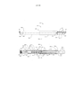
[0020] A FIG. 5 ilustra um dispositivo de osteotomia de fatia ajustável de forma não invasiva colocado em uma tíbia de acordo com uma primeira concretização da presente invenção colocada em uma tíbia.[0020] FIG. 5 illustrates a non-invasively adjustable slice osteotomy device placed in a tibia in accordance with a first embodiment of the present invention placed in a tibia.
[0021] A FIG. 6 ilustra uma vista do dispositivo em osteotomia em fatiaajustável de forma não invasiva da FIG. 5.[0021] FIG. 6 illustrates a view of the non-invasively adjustable slice osteotomy device of FIG. 5.
[0022] A FIG. 7 ilustra uma vista detalhada do grampo inferior do dispositivo em osteotomia em fatiaajustável de forma não invasiva das FIGS. 5 e 6.[0022] FIG. 7 illustrates a detailed view of the lower clip of the non-invasively adjustable slice osteotomy device of FIGS. 5 and 6.
[0023] A FIG. 8 ilustra uma concretização de um implante magneticamente ajustável.[0023] FIG. 8 illustrates an embodiment of a magnetically adjustable implant.
[0024] A FIG. 9 ilustra um dispositivo de osteotomia de fatia ajustável de forma não invasiva com base em um elemento de mola de acordo com uma segunda concretizaçãoda presente invenção.[0024] FIG. 9 illustrates a non-invasively adjustable slice osteotomy device based on a spring element in accordance with a second embodiment of the present invention.
[0025] A FIG. 10 ilustra um dispositivo de osteotomia de fatia ajustável de forma não invasiva com base em um ascensor ligado de acordo com uma terceira concretizaçãoda presente invenção.[0025] FIG. 10 illustrates a non-invasively adjustable slice osteotomy device based on an attached lift in accordance with a third embodiment of the present invention.
[0026] A FIG. 11 ilustra o dispositivo em osteotomia em fatiaajustável de forma não invasiva da FIG. 9 a ser inserido em uma abertura de fatia em uma tíbia.[0026] FIG. 11 illustrates the non-invasively adjustable slice osteotomy device of FIG. 9 to be inserted into a slice opening in a tibia.
[0027] A FIG. 12 ilustra um dispositivo de osteotomia fatia ajustável de forma não invasiva com base em uma tomada de tesoura de acordo com uma quarta concretizaçãoda presente invenção.[0027] FIG. 12 illustrates a non-invasively adjustable slice osteotomy device based on a scissors socket in accordance with a fourth embodiment of the present invention.
[0028] A FIG. 13 ilustra o dispositivo em osteotomia em fatiaajustável de forma não invasiva da FIG. 12 com a interface do osso superior removida para mostrar o mecanismo de tomada de corte.[0028] FIG. 13 illustrates the non-invasively adjustable slice osteotomy device of FIG. 12 with the upper bone interface removed to show the cut-off mechanism.
[0029] A FIG. 14 ilustra uma vista em corte do dispositivo de osteotomia fatia ajustável de forma não invasiva das FIGS. 12 e 13.[0029] FIG. 14 illustrates a cross-sectional view of the non-invasively adjustable slice osteotomy device of FIGS. 12 and 13.
[0030] A FIG. 15 ilustra uma vista em perspectiva de um dispositivo de ajuste externo.[0030] FIG. 15 illustrates a perspective view of an external adjustment device.
[0031] A FIG. 16 ilustra uma vista explodida de uma peça de mão magnético do dispositivo de ajuste externo da FIG. 15.[0031] FIG. 16 illustrates an exploded view of a magnetic handpiece of the external adjustment device of FIG. 15.
[0032] A FIG. 17 ilustra um dispositivo de osteotomia fatia ajustável de forma não invasiva de acordo com uma quinta concretização da presente invenção.[0032] FIG. 17 illustrates a non-invasively adjustable slice osteotomy device in accordance with a fifth embodiment of the present invention.
[0033] A FIG. 18 ilustra uma vista em corte do dispositivo de osteotomia fatia ajustável de forma não invasiva da FIG. 17.[0033] FIG. 18 illustrates a cross-sectional view of the non-invasively adjustable slice osteotomy device of FIG. 17.
[0034] A FIG. 19 ilustra uma vista explodida do dispositivo de osteotomia fatia ajustável de forma não invasiva da FIG. 17.[0034] FIG. 19 illustrates an exploded view of the non-invasively adjustable slice osteotomy device of FIG. 17.
[0035] Figs. 20 a 27 ilustram um método de implantação e do funcionamento de um dispositivo de osteotomia fatia ajustável não-invasiva para a manutenção ou o ajuste de um ângulo de fatia de uma osteotomia abertura da tíbia de um paciente.[0035] Figs. 20-27 illustrate a method of implanting and operating a non-invasive adjustable slice osteotomy device for maintaining or adjusting a slice angle of an osteotomy opening a patient's tibia.
[0036] A FIG. 28 ilustra eixos de distração em uma tíbia.[0036] FIG. 28 illustrates axes of distraction in a tibia.
[0037] Figs. 29 a 31 ilustram um método de implantação e do funcionamento de um dispositivo de osteotomia fatia ajustável não-invasiva para a manutenção ou o ajuste de um ângulo de um fecho osteotomia em fatiada tíbia de um paciente.[0037] Figs. 29 to 31 illustrate a method of implanting and operating a non-invasive adjustable slice osteotomy device for maintaining or adjusting an angle of a sliced tibia osteotomy closure in a patient.
[0038] A FIG. 32 ilustra um sistema para a escavação de material ósseo de acordo com uma primeira concretizaçãoda presente invenção.[0038] FIG. 32 illustrates a system for excavating bone material in accordance with a first embodiment of the present invention.
[0039] A FIG. 33 ilustra uma rotação de ferramenta de corte do sistema da FIG. 32.[0039] FIG. 33 illustrates a cutting tool rotation of the system of FIG. 32.
[0040] A FIG. 34 ilustra uma vista lateral da ferramenta de corte rotativa da FIG. 33.[0040] FIG. 34 illustrates a side view of the rotary cutting tool of FIG. 33.
[0041] A FIG. 35 ilustra uma vista em corte da ferramenta de corte rotativa da FIG. 34, tomada ao longo da linha 35-35.[0041] FIG. 35 illustrates a cross-sectional view of the rotary cutting tool of FIG. 34, taken along line 35-35.
[0042] A FIG. 36 ilustra uma unidade de acionamento do sistema da FIG. 32 com revestimento removido.[0042] FIG. 36 illustrates a drive unit of the system of FIG. 32 with coating removed.
[0043] A FIG. 37 ilustra o sistema da FIG. 32 em lugar dentro de uma tíbia.[0043] FIG. 37 illustrates the system of FIG. 32 in place inside a tibia.
[0044] A FIG. 38 ilustra o sistema da FIG. 32 após a remoção de material osséo da tíbia.[0044] FIG. 38 illustrates the system of FIG. 32 after removal of bone material from the tibia.
[0045] A FIG. 39 ilustra um sistema para a escavação de material ósseo de acordo com uma segunda concretização da presente invenção em posição no interior da tíbia.[0045] FIG. 39 illustrates a system for excavating bone material in accordance with a second embodiment of the present invention in position within the tibia.
[0046] A FIG. 40 ilustra o sistema da FIG. 39 em uma configuração expandida no interior da tíbia.[0046] FIG. 40 illustrates the system of FIG. 39 in an expanded configuration inside the tibia.
[0047] A FIG. 41 ilustra uma vista de extremidade de um braço com uma superfície abrasiva, como parte de um dispositivo de escavação do sistema da FIG. 39.[0047] FIG. 41 illustrates an end view of an arm with an abrasive surface as part of an excavating device of the system of FIG. 39.
[0048] A FIG. 42 ilustra um sistema para a escavação de material ósseo de acordo com uma terceira concretização da presente invenção em posição no interior da tíbia.[0048] FIG. 42 illustrates a system for excavating bone material in accordance with a third embodiment of the present invention in position within the tibia.
[0049] A FIG. 43 ilustra o sistema da FIG. 42 em uma configuração expandida no interior da tíbia.[0049] FIG. 43 illustrates the system of FIG. 42 in an expanded configuration inside the tibia.
[0050] A FIG. 44 ilustra uma vista de extremidade de um braço com uma superfície de compactação, como parte de um dispositivo de escavação do sistema da FIG. 42.[0050] FIG. 44 illustrates an end view of an arm with a compaction surface as part of an excavating device of the system of FIG. 42.
[0051] A FIG. 45A ilustra um dispositivo em osteotomia em fatiaajustável de forma não invasiva de acordo com uma sexta concretizaçãoda presente invenção.[0051] FIG. 45A illustrates a non-invasively adjustable slice osteotomy device in accordance with a sixth embodiment of the present invention.
[0052] A FIG. 45B ilustra o dispositivo em osteotomia em fatiaajustável de forma não invasiva da FIG. 45 A em uma vista em perspectiva.[0052] FIG. 45B illustrates the non-invasively adjustable slice osteotomy device of FIG. 45 A in a perspective view.
[0053] A FIG. 46 ilustra uma vista detalhada do dispositivo de osteotomia fatia ajustável de forma não invasiva da FIG. 45B tomada de dentro círculo 46.[0053] FIG. 46 illustrates a detailed view of the non-invasively adjustable slice osteotomy device of FIG. 45B taken from inside
[0054] A FIG. 47 ilustra o dispositivo em osteotomia em fatiaajustável de forma não invasiva da FIG. 45A em uma primeira posição distração.[0054] FIG. 47 illustrates the non-invasively adjustable slice osteotomy device of FIG. 45A in a distraction first position.
[0055] A FIG. 48 ilustra o dispositivo em osteotomia em fatiaajustável de forma não invasiva da FIG. 45A em uma segunda posição distração.[0055] FIG. 48 illustrates the non-invasively adjustable slice osteotomy device of FIG. 45A in a second distraction position.
[0056] A FIG. 49 ilustra uma vista em corte do dispositivo de osteotomia fatia ajustável de forma não invasiva da FIG. 45 A em uma primeira posição distração.[0056] FIG. 49 illustrates a cross-sectional view of the non-invasively adjustable slice osteotomy device of FIG. 45 A in a distraction first position.
[0057] A FIG. 50 ilustra uma vista em corte do dispositivo de osteotomia fatia ajustável de forma não invasiva da FIG. 45 A em uma segunda posição distracção.[0057] FIG. 50 illustrates a cross-sectional view of the non-invasively adjustable slice osteotomy device of FIG. 45 A in a second distraction position.
[0058] A FIG. 51 ilustra uma bucha do dispositivo em osteotomia em fatiaajustável de forma não invasiva da FIG. 45 A.[0058] FIG. 51 illustrates a bushing of the non-invasively adjustable slice osteotomy device of FIG. 45 A.
[0059] Figs. 52 a 55 ilustram um método de implantação e de funcionamento do dispositivo em osteotomia em fatiaajustável de forma não invasiva da FIG. 45A para a manutenção ou o ajuste de um ângulo de uma osteotomia de fatia aberta da tíbia de um paciente.[0059] Figs. 52-55 illustrate a method of implanting and operating the non-invasively adjustable slice osteotomy device of FIG. 45A for maintaining or adjusting an angle of a patient's tibial open-slice osteotomy.
[0060] Figs. 56A a 56D ilustram configurações de parafusos de osso para o dispositivo em osteotomia de fatia ajustável de forma não invasiva da FIG. 45A.[0060] Figs. 56A-56D illustrate bone screw configurations for the non-invasively adjustable slice osteotomy device of FIG. 45A.
[0061] A FIG. A figura 57 apresenta um dispositivo em osteotomia de fatia ajustável de forma não invasiva de acordo com uma sétima concretizaçãoda presente invenção.[0061] FIG. Fig. 57 shows a non-invasively adjustable slice osteotomy device in accordance with a seventh embodiment of the present invention.
[0062] A FIG. 58 ilustra uma âncora de osso para utilização com o dispositivo em osteotomia de fatia ajustável de forma não invasiva da FIG. 57.[0062] FIG. 58 illustrates a bone anchor for use with the non-invasively adjustable slice osteotomy device of FIG. 57.
[0063] Figs. 59 a 61 ilustram um método de implantação e de funcionamento do dispositivo em osteotomia de fatia ajustável de forma não invasiva da FIG. 57 para a manutenção ou o ajuste de um ângulo de fatia de uma osteotomia abertura da tíbia de um paciente.[0063] Figs. 59-61 illustrate a method of implanting and operating the device in the non-invasively adjustable slice osteotomy of FIG. 57 for maintaining or adjusting a slice angle of an osteotomy opening a patient's tibia.
[0064] A FIG. 62 ilustra um dispositivo de osteotomia de fatia ajustável de forma não invasiva de acordo com uma oitava concretizaçãoda presente invenção em uma primeira posição distracção.[0064] FIG. 62 illustrates a non-invasively adjustable slice osteotomy device in accordance with an eighth embodiment of the present invention in a first distraction position.
[0065] A FIG. 63 ilustra o dispositivo de osteotomia em fatia ajustável de forma não invasiva da FIG. 62 em uma segunda posição de distração.[0065] FIG. 63 illustrates the non-invasively adjustable slice osteotomy device of FIG. 62 in a second distraction position.
[0066] A FIG. 64A ilustra um atuador magnético ajustável de um dispositivo em osteotomia em fatia ajustável de forma não invasiva de acordo com uma concretização da presente invenção durante a remoção de um conjunto magnético.[0066] FIG. 64A illustrates an adjustable magnetic actuator of a non-invasively adjustable slice osteotomy device according to one embodiment of the present invention during removal of a magnetic assembly.
[0067] A FIG. 64B ilustra o atuador magneticamente ajustável da FIG. 64A após a remoção de um conjunto magnético.[0067] FIG. 64B illustrates the magnetically adjustable actuator of FIG. 64A after removing a magnet assembly.
[0068] A FIG. 64C ilustra a FIG atuador magneticamente ajustável da FIG. 64A após a substituição de uma tampa de compartimento do atuador.[0068] FIG. 64C illustrates the magnetically adjustable actuator FIG of FIG. 64A after replacing an actuator housing cover.
[0069] A FIG. 65 A ilustra um atuador magnético ajustável de um dispositivo em osteotomia em fatia ajustável de forma não invasiva de acordo com uma concretizaçãoda presente invenção, antes da remoção de um íman permanente radialmente polarizado.[0069] FIG. 65A illustrates an adjustable magnetic actuator of a non-invasively adjustable slice osteotomy device in accordance with one embodiment of the present invention, prior to removal of a radially polarized permanent magnet.
[0070] A FIG. 65B ilustra o atuador magneticamente ajustável da FIG. 65A durante a remoção do ímã permanente radialmente-polarizado.[0070] FIG. 65B illustrates the magnetically adjustable actuator of FIG. 65A during removal of the radially-polarized permanent magnet.
[0071] A FIG. 65C ilustra o atuador magneticamente ajustável da FIG. 64 A, depois de remoção do íman permanente radialmente polarizado e substituição de uma tampa da caixa magnético.[0071] FIG. 65C illustrates the magnetically adjustable actuator of FIG. 64 A, after removal of the radially polarized permanent magnet and replacement of a magnetic housing cover.
[0072] A FIG. 65D ilustra o atuador magneticamente ajustável da FIG. 64 A, após a substituição de uma tampa de compartimento do atuador.[0072] FIG. 65D illustrates the magnetically adjustable actuator of FIG. 64 A, after replacing an actuator housing cover.
[0073] Figs. 66 a 69 ilustram esquematicamente várias concretizações de fontes alternativas de um elemento de acionamento de um dispositivo de osteotomia fatia ajustável de forma não invasiva.[0073] Figs. 66-69 schematically illustrate various embodiments of alternative sources of a drive element of a non-invasively adjustable slice osteotomy device.
[0074] A FIG. 1 ilustra um alinhamento padrão de um fémur 100, e uma tíbia 102 uma articulação de joelho 104, em que a articulação do quadril (na cabeça fémur 108), uma articulação de joelho 104 e uma articulação do tornozelo (na linha média da tíbia distal 110) são orientadas ao longo de uma única linha 112. A fíbula 106 é mostrada ao lado da tíbia 102. A articulação do joelho 104 da FIG. 2 é mostrada em um estado artrítico, em que um compartimento medial 114 foi comprometido, fazendo com que a linha 112 a passar medialmente fora do centro da articulação do joelho 104.[0074] FIG. 1 illustrates a standard alignment of a
[0075] A FIG. 3 ilustra uma osteotomia em fatia aberta 118 formada por meio de corte ao longo de uma linha de corte 120, e um ângulo de fatia aberta da FIG. 4 ilustra a configuração final desta fatia aberta pela colocação de material de enxerto ósseo no interior da abertura 122 osteotomia em fatia 118, e, em seguida, a colocação de uma placa 124, que é então fixada à tíbia 102 com parafusos tibiais 126.[0075] FIG. 3 illustrates an
[0076] A FIG. 5 ilustra uma tíbia 102 com um dispositivo não-invasivo de osteotomia fatia ajustável 128 implantado. O O dispositivo de osteotomia de fatia ajustável de forma não invasiva 128 é mostrado sem a tíbia 102 na FIG. 6. O dispositivo de osteotomia de fatia ajustável de forma não invasiva 128 inclui um atuador 142 que compreende um invólucro exterior 130 e uma haste interna 132 acoplada telescopicamente dentro do invólucro exterior 130 para o ajuste longitudinal não-invasiva. Para implantar o O dispositivo de osteotomia de fatia ajustável de forma não invasiva 128, um orifício 138 é perfurado na tíbia 102, e, em seguida, é feito um corte ao longo da linha de corte 120. O atuador 142 é então inserido, a extremidade distal 140 em primeiro lugar, para dentro do buraco 138. Uma abertura 144 de fatia é aberto o suficiente para ser capaz de inserir um elemento de suporte inferior 136 e um suporte superior 134. O suporte inferior 136, como visto na FIG. 7, tem uma abertura 146 e um diâmetro interno 148 que permitem que ele seja encaixado sobre uma ranhura circunferencial 150 em torno do alojamento exterior 130. O suporte inferior 136 é então fixado à tíbia 102 na porção inferior 152 da abertura 144 por fatia colocação de parafusos de osso (não representados) através dos orifícios 154. suporte superior 134 é, então, caiu no lugar e fixado a uma extremidade proximal 156 do atuador 142, apertando um parafuso de aperto 158 que alinha através de um furo rosqueado no eixo interior 132 do atuador 142. O suporte superior 134 é então fixado à tíbia 102 na porção superior 162 da abertura da fatia 144 colocando parafusos de osso (não mostrados) através dos orifícios 164.[0076] FIG. 5 illustrates a
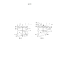
[0077] A FIG. 8 ilustra um atuador magnético ajustável 142 que pode ser utilizado nas concretizações das Figs. 5-7, ou de outras concretizações aqui descritas. Um eixo interior 132, que tem uma extremidade 160, é telescopicamente ajustável dentro de um alojamento exterior 130 através da utilização de um conjunto magnético 166 nela contida. O conjunto magnético 166 compreende um radialmente polarizado, ímã cilíndrico 168 que se envolve com um ou mais estágios de engrenagens planetárias 170. A engrenagem planetária encena a saída 170 para um parafuso de avanço 172. Em algumas modalidades, o palco da engrenagem final 170 pode ser preso à parafuso de avanço 172 com um pino de alta resistência, por exemplo, um pino construído a partir de aço inoxidável série 400. O eixo interno 132 contém uma cavidade 174 na qual se encontra ligado uma porca 176 que tem uma rosca fêmea que interage com a rosca macho do parafuso de avanço 172. Um rolamento radial 178 e um rolamento de impulso 180 permitem que o conjunto magnético 166 para operar com relativamente baixa atrito. Um anel de vedação 182 é mantido dentro de uma ranhura circunferencial no interior da parede do invólucro exterior 130, e o diâmetro interno do anel de vedação 182 veda dinamicamente o diâmetro exterior do eixo interior 132.[0077] FIG. 8 illustrates an adjustable
[0078] Voltando à FIG. 5, o dispositivo de osteotomia de fatia ajustável de forma não invasiva 128 é usado para abrir gradualmente a abertura 144 da fatia ao longo do tempo. Através da aplicação de um campo magnético em movimento a partir de uma localização relativa externo ao paciente, por exemplo, depois de o paciente ter recuperado da cirurgia, o atuador 142 da FIG. 6 pode ser gradualmente aumentado (por exemplo, cerca de um (1) mm por dia), permitindo a abertura de fatia 144 para atingir o ângulo desejado, o que pode ser testado por ter o paciente realizar estudos de movimento diferentes (pisando, torneamento, etc.), até que a condição mais confortável é atingida. Alongamento gradual pode permitir a possibilidade de Ilizarov osteogênese, em que novas formas materiais óssea na abertura de fatia como ele é aberto. Nesse modo, de um enxerto ósseo pode ser desnecessário. Após o ângulo de abertura da fatia 144 desejado é atingido, o material de osso recentemente crescido pode ser permitido para consolidar. Se, durante o processo, o alongamento tem sido demasiado rápida, ou osso novo não tem suficientemente consolidada, um campo magnético em movimento pode ser aplicado em uma direção oposta encurtando assim o atuador 142 para aumentar a compressão e criar uma boa dimensão para a formação de calos. Depois de confirmar que a formação do calo suficiente tenha ocorrido, o alongamento pode ser retomado com a mesma velocidade, ou a uma velocidade diferente. Uma vez concluído o alongamento é suficientemente, e osso consolidada é estável, pode ser desejável remover todo o dispositivo de osteotomia de fatia ajustável não-invasiva 128, ou simplesmente o conjunto magnético 166.[0078] Returning to FIG. 5, the non-invasively adjustable
[0079] A FIG. 9 ilustra um dispositivo de osteotomia de fatia ajustável de forma não invasiva 184 em conjunto magnético compreendendo um íman 192, incluindo, por exemplo, um íman cilíndrico radialmente polarizado 186, que está acoplado a um parafuso de acionamento 188. Como íman cilíndrico radialmente polarizado radialmente 186 está ligado por uma aplicado externamente campo magnético em movimento, o parafuso de accionamento 188 gira dentro de um bloco 190 tendo uma rosca fêmea, fazendo com que o conjunto do parafuso de accionamento 188 e ímã 192 para ser movido em uma direção axial em primeiro lugar (A). À medida que o conjunto magnético 192 move-se axialmente que empurra uma memória de formato curvo (por exemplo, super elástico Nitinol®) placa de mola 194 no ponto de ligação 196. Um rolamento de encosto 198 no ponto de ligação 196 permite a rotação contínua do íman cilíndrica radialmente 186 como polarizado a força aumenta. Como uma curva interior 200 da mola de prato 194 é pressionado de Nitinol na primeira direção axial (A), a largura (W) da mola de prato 194 aumenta o Nitinol. Um recorte 202 na primavera placa Nitinol 194 oferece espaço para o ímã cilíndrico radialmente polarizado 186 para ligar e para se mover na direção primeira axial (A).[0079] FIG. 9 illustrates a non-invasively adjustable
[0080] A FIG. 10 ilustra um dispositivo de osteotomia de fatia ajustável de forma não invasiva 216 similar ao dispositivo de osteotomia de fatia ajustável de forma não invasiva 184 da FIG. 9, exceto que a mola da placa de nitinol 194 da FIG. 9 é substituída por um ascensor de ligação 204. O ascensor 204 compreende uma placa inferior 206 e uma placa superior 208, que estão ligados a um bloco 190 por meio de pinos 210, que permitem a cada placa 206 e 208 para aumentar a angulação ao longo das setas (B). As placas 206 e 208 estão ligadas a placas interiores 212 e 214 por meio de pinos 210. A estrutura articulada de placas interiores 212, 214 é empurrado para a frente de uma forma semelhante como o Nitinol placa de mola 194 é empurrada na direção axial primeiro (A) na fig. 9.[0080] FIG. 10 illustrates a non-invasively adjustable
[0081] A FIG. 11 ilustra um dispositivo de osteomia de fatia ajustável de forma não invasiva 184 que está sendo colocado em uma abertura de fatia 144 em uma tíbia 102. O dispositivo de osteomia de fatia ajustável de forma não invasiva 216 da FIG. 10 pode ser inserido na mesma maneira.[0081] FIG. 11 illustrates a non-invasively adjustable
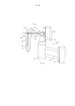
[0082] As Figs. 12 a 14 ilustram um dispositivo de osteomia de fatia ajustável de forma não invasiva 218 com base em uma tesoura manual. O dispositivo de osteomia de fatia ajustável de forma não invasiva 218 compreende um invólucro principal 220 que tem uma interface osso inferior 222 e uma interface osso superior 224, a interface 224 osso superior que pode ser ajustada com respeito ao invólucro principal 220 e o osso inferior da interface 222. A FIG . 13 mostra um dispositivo de osteomia de fatia ajustável de forma não invasiva 218 com a interface osso superior 224 removido para melhor apreciar os componentes internos. Um conjunto de tesoura 225 compreende uma primeira tesoura 226 e uma segunda tesoura 228, que pode ser acoplada por meio de um pino central 230 de uma forma articulada. Braços distais 234 e 238 226 de tesoura e 228 podem ser acoplados às extremidades distais da interface osso inferior 222 e 224 de interface do osso superior por um braço 240. Os pinos 232 da segunda tesoura 228 é acoplado a uma interligação 242 de um campo magnético montagem 244 com um pino 240. Um conjunto magnético oco 246 tem roscas internas 247 que se engatam roscas externas 249 de um parafuso de avanço 248 que está ligado à interconexão 242. O conjunto magnético oco 246 pode compreender um íman polarizado radialmente oco. A interligação 242 inclui uma lingueta 251, que é capaz de engatar os dentes 253 de uma placa de roquete 255. Como aplicado externamente em movimento faz com que o campo magnético do íman 246 a rodar, o parafuso de avanço 248 e a interligação 242 são movidos em uma primeira direção axial (A), fazendo com que a montagem 225 uma tesoura para abrir- se, e, assim, aumentar a distância (D) entre a interface osso inferior 222 e a interface do osso superior 224. Um braço 236 da primeira tesoura 226 é capaz de deslizar dentro de um canal 257 em a interface do osso superior 224. A lingueta 251 e os dentes 253 da placa 255 de roquete formar um uma maneira de roquete, permitindo que a distância (D) a ser aumentado, mas não diminuiu.Figs. 12-14 illustrate a non-invasively adjustable
[0083] A FIG. 15 ilustra um dispositivo de ajuste externo 1180 que é utilizado para ajustar de forma não invasiva dos dispositivos e sistemas aqui descritos. O dispositivo de ajuste externo 1180 compreende uma peça magnética manual 1178, uma caixa de controle 1176 e uma fonte de alimentação 1174. O controle de caixa de 1 176 inclui um painel de controle de um 182 com um ou mais controles (botões, chaves e tátil, movimento, áudio ou sensores de luz) e um monitor 1 184. O display 1184 pode ser visual, auditiva, tátil, etc., ou uma combinação das características acima mencionadas. O dispositivo de ajuste externo 1180 pode conter software que permite a programação pelo médico.[0083] FIG. 15 illustrates an
[0084] A FIG. 16 mostra em melhores detalhes a peça mangnética manual 1178 do dispositivo de ajuste externo 1 180. Como visto na FIG. 16, existem uma pluralidade de, por exemplo, dois (2), os imans 1186 tendo uma forma cilíndrica (também, outras formas são possíveis). Os ímans 1186 podem ser feita a partir de ímãs de terras raras, e pode em algumas concretizações ser radialmente polarizados. Os ímãs 1186 estão ligados ou não garantidos dentro de copos magnéticos 1187. Os copos magnéticos 1 187 incluem um eixo de 1198, que está ligado a uma primeira marcha ímã 1212 e uma segunda marcha ímã 1214, respectivamente. A orientação dos pólos de cada um dos dois ímans 186 são mantidos em relação ao outro por meio do sistema de mudanças (por utilização de engrenagem central 1210, que engrena com a primeira roda dentada tanto íman 1212 e segunda engrenagem íman 1214). Em uma concretização, o pólo norte de um dos ímãs 1186 gira sincronizadamente com o pólo sul do outro íman 1186, em posições correspondentes do relógio ao longo de uma rotação completa. A configuração tem sido conhecida para proporcionar uma entrega melhorada do binário, por exemplo, íma cilíndrico 168 ou 246. Exemplos de métodos e concretizações de dispositivos de regulação externos que podem ser utilizados para ajustar a forma não invasiva fatia ajustável dispositivo de osteotomia 218, ou outra concretizações da presente invenção, estão descritos na na patente norte-americana N° US 8,382,756, a divulgação da qual é aqui incorporada por referência na sua totalidade, e no pedido de patente serial No. US 13/172,598 que foi publicado com o número de publicação US 2012/0004494 Al, a divulgação da qual é aqui incorporada por referência na sua totalidade.[0084] FIG. 16 shows in better detail the
[0085] Os componentes da peça magnética manual 1178 são mantidas juntas entre a placa de íman 1 190 e uma placa frontal 1 192. A maior parte dos componentes são protegidos por uma tampa 1216. Os ímans 1 186 girar dentro de um íman estático cobrir 188, de modo que a peça magnética manual 1178 pode ser colocada diretamente no paciente, enquanto não transmitir qualquer movimento para as superfícies externas do paciente. Antes de se distrair o dispositivo intramedular alongamento 1110, o operador coloca a peça magnética manual 1178 através do paciente perto do local do íman cilíndrico 1134. Um suporte isolador de íman 194 que está interposta entre os dois ímãs 1186 contém uma janela de visualização 1196, para auxiliar na colocação. Por exemplo, uma marca feita na pele do paciente no local apropriado, com um marcador indelével pode ser visto através da janela de visualização 1196. Para realizar uma distracção, o operador detém a peça magnética manual 1178 por suas alças de 1200 e deprime um interruptor distral 1228, fazendo o motor 1202 dirigir em um primeiro sentido. O motor 1202 tem uma caixa de engrenagens 1206 que faz com que a velocidade de rotação de uma engrenagem de saída 1204 para ser diferente da velocidade de rotação do motor 1202 (por exemplo, uma velocidade mais lenta). A engrenagem de saída 1204, em seguida, vira uma engrenagem de redução 1208 que engrena com a engrenagem do centro de 1210, fazendo-o girar a uma velocidade de rotação diferente do que a engrenagem de redução 1208. A engrenagem do centro 1210 malhas tanto com a primeira marcha ímã 1212 e a engrenagem segundo ímã 1214 transformando-os a uma taxa que é idêntica a outra. Dependendo da parte do corpo onde os ímãs 1186 do dispositivo de ajuste externo 1180 estão localizadas, deseja-se que esta taxa seja controlado, para minimizar a densidade da corrente induzida resultante transmitido pelo íman 1 186 e 1 134 íman cilíndrico embora o tecidos e fluidos do corpo. Por exemplo, uma velocidade de rotação do íman 60 RPM ou menos é contemplado embora outras velocidades possam ser utilizadas, tais como 35 RPM ou menos. A qualquer momento, a distração pode ser reduzida, pressionando o interruptor de retração 1230, o que pode ser desejável se o paciente sente dor, ou dormência na área segurando o aparelho.[0085] The components of the
[0086] As Figs. 17 a 19 ilustram um dispositivo de osteomia de fatia ajustável de forma não invasiva 300 compreendendo um atuador magnético ajustável 342 que tem uma primeira extremidade 326 e uma segunda extremidade 328. Um eixo interior 332 que tem uma cavidade 374 está acoplada telescopicamente dentro de um invólucro exterior 330, que compreende uma strutura de distração 312 e uma caixa de engrenagens 306. Pelo menos um orifício transversal 305 passa através de uma tampa de extremidade 302 localizado na primeira extremidade 326 do atuador magneticamente ajustável 342. A tampa de extremidade 302 pode ser fixada de forma estanque para a caixa de engrenagens 306 por uma união de soldagem circunferencial 390. Uma segunda união de soldagem 392 protege de forma estanque o invólucro de distração 312 na caixa da engrenagem 306. Um ou mais furos transversais 364 passe através do eixo interno 332. O um ou mais furos transversais 364 e o pelo menos um furo transversal 305 permite passagem de, pelo menos, um parafuso de bloqueio. Algumas concretizações utilizam apenas um orifício transversal 364 e um furo transversal 305, de modo a melhor permitir que o jogo de rotação entre o atuador magneticamente ajustável 342 e os parafusos de aperto como o atuador magneticamente ajustável 342 é ajustado. Uma ou mais ranhuras longitudinais 372 na superfície exterior do eixo interior 332 engatar de um modo codificado com saliências 375 em um anel anti-rotação 373 que engata dentro de rebaixos extremidade do invólucro 312 distracção a uma borda plana 384 do anti- rotação anel 373. Um ou mais guia de aletas 383 no anel anti- rotação 373 pode manter o anel anti-rotação 373 rotativamente estático dentro de cortes de 391 na estrutura de distração 312.[0086] Figs. 17-19 illustrate a non-invasively adjustable
[0087] O conteúdo do atuador magneticamente ajustável 342 são protegidos dos fluidos corporais por uma ou mais juntas tóricas 334 que residem dentro das ranhuras circunferenciais 382 no eixo interno 332, a vedação dinâmica ao longo da superfície interna do invólucro 312. O interior do eixo de distração 332 é acionado axialmente em relação ao invólucro exterior 330 por um parafuso de avanço 348 que está ligado por um íman cilíndrico polarizado radialmente 368. O íma cilíndrico radialmente polarizado 368 está ligado dentro de um primeiro alojamento de íman 308 e um segundo alojamento 310 e o ímã é rotativamente realizado em um pino 336 em uma das extremidades por um rolamento radial 378, que envolve diretamente o rebaixo 304 da tampa 302. A segunda habitação ímã 310 saídas em uma primeira etapa 367 de três estágios de engrenagens planetárias 370. As engrenagens planetárias 387 de a engrenagem planetária de três fases 370 por sua vez, dentro de dentes interior 321 no interior da caixa de engrenagens 306. A primeira fase 367 sai para uma segunda fase 369, e a segunda fase 369 sai para uma terceira etapa 371. A terceira fase 371 é acoplada ao fuso rosqueado 348 por um pino de travamento 385, que passa através dos furos 352 em ambas as saídas da terceira fase 371 e no parafuso de avanço 348. Um acoplador de parafuso de avanço 339 é também mantido ao parafuso de avanço 348 do pino 385, o qual passa através de um orifício 359. O parafuso guia 348 rosqueado engata uma porca 376 que está ligado no interior da cavidade 374 da haste interna 332. Cada fase de engrenagens planetárias 370 incorpora uma proporção de engrenagem 4:1, produzindo uma relação de transmissão total de 64:1, assim 64 voltas do íma cilíndrico radialmente polarizado 368 causa uma única volta do parafuso de chumbo 348. Um rolamento de encosto 380, realiza-se vagamente na direção axial entre bordas na caixa de engrenagens 306. O engate de parafuso de chumbo 339 inclui uma saliência 355, que é semelhante a uma borda oposta (não representada) na base do fuso rosqueado 348. Se o eixo interno 332 é retraído para o comprimento mínimo, a borda na base do parafuso de avanço 348 confina com o ressalto 355 do parafuso de avanço acoplador, assegurando que o parafuso de avanço 348 não pode ser prensado contra a porca com muito alta, de um binário. O rolamento de encosto 380 é realizado entre uma borda 393 na caixa de engrenagens 306 e uma inserção 395 no final da caixa de engrenagens 306. O rolamento de encosto 380 serve para proteger o íma cilíndrico radialmente polarizado 368, a a engrenagem planetária encena 370, os invólucros de ímas308 e 310, bem como o rolamento radial 378 de danos devido à compressão. Um membro de manutenção 346 compreendendo um arco fina de material magnético, tal como aço inoxidável "série 400 ', está ligado dentro da caixa de engrenagens 306, adjacente ao ímã cilíndrico polarizado radialmente 368, e pode atrair um pólo do íma cilíndrico radialmente polarizado 368, a fim de minimizar a possibilidade do íma cilíndrico radialmente polarizado 368 virar quando não está sendo ajustado pelo dispositivo de ajuste externo 1180, por exemplo, durante o movimento do paciente.[0087] The contents of the magnetically
[0088] O dispositivo de osteomia de fatia ajustável de forma não invasiva 300 tem a capacidade para aumentar ou diminuir o seu comprimento, pelo menos, cerca de três milímetros de cada direção, em uma concretização, e cerca de nove milímetros de cada direção em outra forma de realização. O dispositivo de osteomia de fatia ajustável de forma não invasiva 300 pode alcançar uma força de distração de 240 quilos quando a peça magnética manual 1178 do dispositivo de ajuste externo 1180 é colocada para que os ímãs 1186 sejam cerca de meia polegada a partir do íma cilíndrico radialmente polarizado 368. A maioria dos componentes do dispositivo de osteomia de fatia ajustável de forma não invasiva pode ser feito a partir de titânio ou ligas de titânio, tais como titânio-6A1-4V, cromo, cobalto, aço inoxidável ou outras ligas. Quando implantada, o dispositivo de osteomia de fatia ajustável de forma não invasiva 300 pode ser inserido manualmente ou pode ser ligado a uma ferramenta de inserção (por exemplo uma guia de perfuração). Uma interface 366 compreende uma rosca interior 397 está localizado na tampa de extremidade 302 para acoplamento reversível com as roscas macho de uma ferramenta de inserção. Alternativamente, estas funcionalidades podem estar localizadas sobre a extremidade 360 da haste interna 332. Além disso, um tirante destacável pode ser ligado a qualquer das extremidades do dispositivo de osteomia de fatia ajustável de forma não invasiva 300, de modo que podem ser facilmente removida, se colocado de forma incorreta.[0088] The non-invasively adjustable
[0089] As Figs. 20 a 27 ilustram um método de implantação e operação de um dispositivo de osteomia de fatia ajustável de forma não invasiva 125 para alterar um ângulo da tíbia de um paciente. Na FIG. 20, uma vista frontal da articulação do joelho direito 104 de um paciente com osteoartrite do joelho é mostrada, incluindo o fêmur 100, tíbia 102 e fíbula 106. O dispositivo de osteomia de fatia ajustável de forma não invasiva 125 pode ser colocado para o lado da tíbia medial 102 (longe do perónio 106). O osso da tíbia 102 é, assim, preparado para permitir uma colocação não central do dispositivo de osteomia de fatia ajustável de forma não invasiva. É feita uma incisão na pele com um lado medial da tíbia 102 e uma osteotomia fatia aberta 118 é feita em relação a um ponto de articulação 107, através da criação de um primeiro corte 103, por exemplo, com uma serra oscilante, e abrindo a abertura osteotomia em fatia1 18, como pode ser visto na FIG. 21. Um local típico para o ponto de articulação 107 pode ser descrito pelas distâncias X e Y na FIG. 20. Em algumas concretizações, X = 10 mm e Y = 15 mm. No ponto de articulação, é comum fazer-se um pequeno furo de perfuração e colocar um pino vértice, por exemplo, um pino de ponta com um diâmetro de cerca de 3 mm a cerca de 4 mm. A osteotomia em fatia aberta 118 agora separa uma primeira parte 119 e a segunda parte 121 da tíbia 102.[0089] Figs. 20-27 illustrate a method of implanting and operating a non-invasively adjustable
[0090] Como pode ser visto na FIG. 22, é feita uma incisão na pele, uma broca 111 é colocado no centro do platô tibial 101 e uma primeira cavidade 109 tendo um primeiro eixo 1 17 é perfurado a partir do platô tibial 101 para dentro do canal medular da tíbia 102. Pode ser desejado durante este passo de perfuração para colocar uma fatia temporária 123 na fatia aberta osteotomia 1 18, a fim de manter a estabilidade. Um diâmetro da broca de cerca de 12 mm ou menos, ou mais preferivelmente cerca de 10 mm ou menos é utilizado para criar a primeira cavidade 109. As FIGS. 23 e 24 ilustram os passos para a criação de um generalizadas segundo uma cavidade 15. Várias concretizações são representados aqui por um dispositivo de escavação 113, o qual é inserido na primeira cavidade 109 através da abertura no prato tibial 101. A segunda cavidade 115 é então formada para um lado da primeira cavidade 109, neste caso, o lado medial. Como mostrado na FIG. 25, após o dispositivo de escavação 1 13 ter sido removida, um dispositivo de osteomia de fatia ajustável de forma não invasiva 125 tendo um invólucro exterior 129 e um eixo interior 127 é inserido na primeira cavidade 109. Na FIG. 25, o dispositivo de osteomia de fatia ajustável de forma não invasiva 125 é mostrado com o eixo interior 127 virado para superiormente (para cima) sobre o paciente, mas pode, em certos casos para o implante do dispositivo de osteomia de fatia ajustável de forma não invasiva 125 com o eixo 127 interno enfrentando inferiormente (para baixo). Primeiro orifício transversal 135 e segundo orifício transversal 137 no dispositivo de osteomia de fatia ajustável de forma não invasiva 125 são configurados para o posicionamento das âncoras ósseas, por exemplo, parafusos de fixação.[0090] As can be seen in FIG. 22, an incision is made in the skin, a
[0091] Na fig. 26, o dispositivo de osteomia de fatia ajustável de forma não invasiva 125 é então colocado dentro da segunda cavidade 115 e fixado com um primeiro meio de ancoragem 131 do primeiro furo transversal 135 e uma segunda âncora 133 através do segundo orifício transversal 137. Com base em cálculos feitos a partir de imagens pré- cirurgia e / ou cirurgia de raios X ou outras imagens, um ângulo de fatia (i é definida entre a primeira porção 19 e uma segunda porção 121 da tíbia. Após a recuperação pós-cirúrgica, o paciente pode retornar para uma sessão de imagem dinâmico (por de raios-x exemplo) durante o qual o paciente fica, e mesmo se move a articulação de joelho 104, a fim de melhor confirmar se o ângulo de fatia i é permite a conformação óptima da articulação do joelho 104. Se, por exemplo, neste momento, for desejado aumentar o ângulo de fatia i, a peça magnética manual 1178 do dispositivo de ajuste externo 1180 da Fig. 15 é então colocada sobre a articulação do joelho do paciente 104 e é operado de modo que a haste interna 127 é distraído a partir do invólucro exterior 129, para aumentar a um ângulo de fatia um maior 2 (FIG. 27). Pode ser desejado para, pelo menos, uma das âncoras (por exemplo segunda âncora 133) para ter uma folga suficiente no orifício transversal (por exemplo, o segundo furo transversal 137), de modo que qualquer angulação que ocorre, enquanto o dispositivo de osteomia de fatia ajustável de forma não invasiva 125 está distraído, não vai colocar um momento de flexão adicionais sobre o dispositivo de osteomia de fatia ajustável de forma não invasiva 125. A sessão de imagem dinâmica pode ser feito em um tempo após a cirurgia, quando o inchaço diminuiu, mas antes da consolidação óssea é significativo. Este período pode ser de aproximadamente uma a duas semanas após a cirurgia. Se for realizado um ajustamento (aumento ou diminuição), uma sessão adicional de imagem dinâmico pode ser realizado, por exemplo, uma semana mais tarde. O dispositivo de osteomia de fatia ajustável de forma não invasiva 125 é fornecido, de modo que ele pode ser alongado ou encurtado ou, em outras palavras, de modo que o ângulo de osteomia de fatia aberta 118 possa ser posteriormente aumentado ou diminuído, dependendo da determinação da desejada correção.[0091] In fig. 26, the non-invasively adjustable
[0092] Uma forma alternativa de quantificar a quantidade de abertura da fatia de abertura osteotomia 1 18, é medir, por exemplo, através de radiografias, a lacuna G1, G2 na borda medial 181 da osteomia de fatia aberta 118. Na faixa típica do ângulo de osteomia de fatia aberta 118, e a faixa típica de tamanhos tíbia 102 de pacientes, a diferença G1, G2 , em milímetros tende a aproximar o ângulo de fatia (X1, 2 em graus. Por exemplo, G1 (mm) ~ 1(°); G2 (mm) ~ 2 (°). Espera- se que, assumindo que seja necessária correção, alongamento produtiva será feita a uma taxa na faixa de cerca de 2 mm de intervalo (G) aumentam por dia, ou menos lacunas aumenta a taxa (GIR), pode ser definida como a mudança no gap em milímetros por dia. Uma consideração na determinação da taxa de aumento do gap (GIR) para usar é a tolerância à dor do paciente. Alguns pacientes podem tolerar uma quantidade maior de dor, por exemplo, a dor provocada pelo alongamento do tecido mole, e, assim, uma taxa de aumento do intervalo superior (GIR). Outra consideração é a quantidade de crescimento de osso que pode ocorrer. Um método para avaliar a quantidade de crescimento ósseo é através de radiografia. O aumento da taxa gap preferido (GIR) é aquela em que o crescimento ósseo está ocorrendo dentro da fatia aberta osteotomia 118, mas a consolidação precoce do osso não está ocorrendo (consolidação que iria "congelar" a mobilidade da fatia aberta osteotomia 118, tornando-o incapaz de ser aberto mais). Pode ser desejável implantar o propositadamente de forma não invasiva dispositivo osteotomia fatia ajustável 125 com uma folga inicial subdimensionado (G0), de modo que um intervalo ideal (G1) pode ser gradualmente alcançado através de ajustes não-invasivos. Está contemplado que, durante o período de ajustamento, um total de um a vinte ou mais procedimentos de ajustamento pode ser realizado, para uma quantidade total de cerca de 1 mm a cerca de 20 mm de aumento de lacuna (G), tal como durante um período de ajustamento de um mês ou menos. Normalmente, o período de adaptação pode se estender por aproximadamente dez dias, envolvem cerca de dez procedimentos de ajuste e envolvem um montante total de cerca de 5 mm a lacuna aumento de cerca de 12 mm.[0092] An alternative way of quantifying the amount of opening of the osteotomy opening slice 1 18 is to measure, for example, through radiographs, the gap G1, G2 at the
[0093] Ao localizar o dispositivo de osteomia de fatia ajustável de forma não invasiva 125 medialmente, na tíbia, em vez de perto da linha central, um momento maior pode ser colocado sobre a primeira porção 119 e uma segunda porção 121 para abrir a fatia de abertura 118 em osteotomia relação ao ponto de articulação 107. Além disso, para uma força de distracção especial aplicado pela forma não invasiva fatia ajustável dispositivo de osteotomia 125, uma maior quantidade de distracção pode ser alcançado. Na FIG. 28, três diferentes eixos de distração (A, B, C) são mostrados, que representa três posições possíveis da forma do dispositivo de osteomia de fatia ajustável de forma não invasiva 125. O eixo de distração A é de aproximadamente a linha média na tíbia 102, enquanto eixo distração B é de cerca de 11° ângular da linha média, e o eixo distração C é de cerca de 22° angular da linha média. O comprimento Dd do ponto de articulação 107 ao eixo de distração B pode ser cerca de 32% maior do que o comprimento Db do ponto de articulação 107 em relação ao eixo de distração A. Mais significativamente, o comprimento Dc do ponto de articulação 107 ao eixo de distração C pode ser de aproximadamente 60% maior do que o o comprimento a partir do ponto de articulação 107 em relação ao eixo de distração A. A força de distração do dispositivo de osteomia de fatia ajustável de forma não invasiva 125 é necessário para ultrapassar uma série de resistências dispostas ao longo da tíbia devido ao efeito de amarração do tecido mole. A colocação do dispositivo de osteomia de fatia ajustável de forma não invasiva 125 ao longo do eixo C e, portanto, na segunda cavidade 115 (FIG. 27) pode permitir uma distração mais eficaz da osteomia de fatia aberta 118.[0093] By locating the non-invasively adjustable
[0094] As Figs. 29 a 31 ilustram um método de implantação e operação de um dispositivo de osteomia de fatia ajustável de forma não invasiva 125 para alterar um ângulo da tíbia de um paciente, mas ao contrário da osteomia de fatia aberta 118 mostrado nas FIGS. 20 a 27, uma osteomia de em fatia fechada 141 é mostrada. Na FIG. 29, o primeiro corte 103 é feita, mas na FIG. 30 um segundo corte 105 é feita e uma fatia de osso é removido. O segundo corte 105 remove propositadamente ligeiramente mais osso do que o necessário para otimizar o ângulo de correção, e como mostrado na FIG. 31, o a osteotomia em fatia fechada 141 é deixado com uma ligeira folga, permitindo-lhe ser ajustada posteriormente em qualquer direção (para aumentar ou diminuir o ângulo de seguida). O método de implantação continua seguindo as etapas restantes descritas nas FIGS. 22 a 26, e o ângulo de osteomia de fatia fechado 141 pode ser aumentado ou diminuído, conforme descrito na FIG. 27.[0094] Figs. 29-31 illustrate a method of implanting and operating a non-invasively adjustable
[0095] As Figs. 32 a 36 ilustram um primeiro sistema para a escavação de material ósseo 400. O sistema para a escavação de materiais osso 400 é configurado para criar uma segunda cavidade 15 de um modo geral como descrito nas FIGS. 22 a 24. Uma unidade de acionamento 404 está acoplado a uma ferramenta de corte rotativa 402 por meio de um trem de acionamento flexível 408. A ferramenta de corte rotativa 402 é uma concretizaçãodo dispositivo de escavação 1 13, conforme apresentada na FIG. 23, mas podem também servir como a broca 111 da FIG. 22. A ferramenta de corte rotativa 402, como representado nas FIGS. 32 a 35, estende-se entre uma primeira extremidade 444 e a segunda extremidade 446 (como mostrado na FIG 34.), e compreende um alargador distal 412 que está acoplado a um alargador proximal 410. Como mostrado na FIG. 35, o alargador distal 412 inclui uma porção de pequeno diâmetro 440, que insere dentro do alargador proximal 410. Um elemento de engate circunferencial 434 é mantido axialmente entre o alargador distal 412 e o alargador proximal 410, e inclui vários recortes 435 (FIG. 34) dispostos em torno da sua circunferência, formando uma polia. O alargador distal 412, alargador proximal 410 e o membro de engajamento circunferencial 434 são realizadas em conjunto com os pinos 437, que são passados através de furos 436, e que garante que todos os componentes girar em uníssono. Um parafuso de fixação 438 é preso dentro de uma rosca fêmea de superfície interna do alargador proximal 410. O alargador distal 412 inclui adicionalmente um cone 442 e uma ponta romba 414. O diâmetro exterior da ferramenta de corte rotativa 402 pode ser de cerca de 12 mm ou menos, e, mais especificamente, cerca de 10 mm ou menos. O diâmetro exterior do escareador proximal 410 pode ser de cerca de 9 mm e o diâmetro exterior do escareador distal pode afunilar de cerca de 9 mm a cerca de 6,35 mm na ponta romba 414. A unidade de acionamento 404, como se vê melhor nas Figs. 32 e 36 compreende uma caixa de transmissão 416 coberta por uma placa de cobertura roldana 418 e uma placa de cobertura da unidade 420. Vários parafusos 421 prendem a placa de cobertura da unidade 420 para a caixa de transmissão 416, e quatro parafusos 426 segurar a placa de cobertura polia 418 ao caixa de accionamento 416. A caixa de accionamento 416 não está representado na FIG. 36, a fim de mostrar mais detalhe dos componentes internos. Na FIG. 32, um fixador 406 é acoplado por meio de parafusos 424 para um identificador de placa de montagem 422 que por sua vez é removivelmente ligados à caixa de acionamento 416 (por exemplo, por meio de parafusos ou de uma pinça).[0095] Figs. 32-36 illustrate a first system for excavating
[0096] Um eixo 428 (Fig. 36) que tem uma extremidade chaveta 430, está configurado para acoplamento amovível a um motor de perfuração elétrico 468 (Figs. 37 e 38). Uma grande polia 450 está ligada ao eixo 428 com um parafuso de ajuste 451, de modo que a rotação do eixo 428 pela unidade de broca elétrica 468 provoca a rotação da polia grande 450. O eixo 428 e grande polia 450 são mantidos entre dois rolamentos de esferas 448 (inferior do rolamento de esferas não visível), e uma anilha de calço 464 e anilha de onda 466 estão localizados em ambos os lados da polia grande 450, a fim de controlar a quantidade de folga axial. Uma roda de rolo 452 está rotativamente ligado à extremidade de uma lâmina de roda de rolamento 456 com um pino 454. O rolo 456 roda corrediça é capaz de deslizar axialmente no interior da caixa de accionamento 416 e unidade placa de cobertura 420 com o afrouxamento de um parafuso de orelhas 432, cujo eixo de rosca se envolve com roscas internas 462 no slide roda do rolo 456. A roda de declice do rolo 456 podem ser garantidos por apertar o parafuso 432 para que ele não deslize durante o uso. A fenda longitudinal 460 na roda deslizante rolo 456 controla o montante total de deslizamento axial, fornecendo uma primeira extremidade 461 e uma segunda extremidade 463 que se encostam uma paragem 458.[0096] A shaft 428 (Fig. 36) having a
[0097] O trem de acionamento flexível 408 compreende uma pequena correia dentada, por exemplo, uma largura de Kevlar® cerca de 3 mm ou de fibra de vidro reforçada correia de poliuretano tendo um binário de deslizamento superior a 10 polegadas-onças quando usado com o grande polia 450 ou o engate circunferencial membro 434. Um exemplo potencial de torque para a derrapagem é de 13 polegadas-onça. Os dentes do trem de accionamento flexível pode ser localizado em um passo de dois milímetros. A FIG. 37 mostra a unidade de acionamento 404 do sistema de escavação de material ósseo 400 acoplado ao motor de perfuração eléctrico 468. O motor de perfuração elétrico 468 inclui um alojamento de motor 476, uma pega 470 e uma bateria 472. A pega pode incluir qualquer número de Interfaces conhecidos na arte para virar o aparelho de broca eléctrica 468 ligado ou desligado, ou controlando a velocidade. Em algumas concretizações, a unidade 468 berbequim pode ligar directamente a uma fonte de alimentação padrão, em vez de ter a bateria 472. A extremidade chaveta 430 do eixo 428 está acoplado a um acoplador do eixo 474 da unidade de broca elétrica 468.[0097]
[0098] Na fig. 37, a primeira cavidade 109 tendo sido criado, o trem de acionamento flexível 408 é inserido através da incisão medial e no aberto osteotomia em fatia1 18, entre a primeira porção de 1 19 e a segunda parte 121 da tíbia. A ferramenta de corte rotativa 402 é então colocada para baixo da primeira cavidade 109 da tíbia 102, de modo, a quantidade desejada que o trem de acionamento flexível 408 em volta em torno do elemento de engate circunferencial 434 da ferramenta de corte rotativa 402. Com o parafuso de polegar 432 solta de tensão na unidade flexível trem 408 é ajustado e em seguida, aperte o polegar 432 é apertada. Nesta tensão desejada, os dentes do trem de acionamento flexível 408 deve relacionar-se bem dentro dos recortes 435 (fig. 34) do membro de engate circunferencial 434 e o rolo 452 roda deve rotativamente contacto a superfície exterior do elemento de engate circunferencial 434, a sua estabilização. A unidade furadeira elétrica 468 é operada, fazendo com que a polia grande 450 da FIG. 36 para rodar o trem de accionamento flexível 408, e assim rodar a ferramenta de corte de rotação 402 através de engate com o elemento de engate circunferencial 434 (FIG. 34). A grande polia 450 pode ser o dobro do diâmetro do membro de engate circunferencial 434, provocando, portanto, a ferramenta de corte rotativa 402 ao girar-se a metade da velocidade da saída da unidade de perfuração eléctrico 468. Outros rácios também estão dentro do âmbito do presente invenção. Pode ser desejável para controlar a velocidade de rotação da ferramenta de corte rotativa 402, a fim de minimizar o aquecimento do osso que circunda o material cortado osso sendo, e, assim, limita os danos ao osso, que possa impedir o crescimento normal durante o processo de cura. Embora a ferramenta de corte rotativa 402 é rodada por a unidade de accionamento 404, O punho 406 é puxado fazendo com que a ferramenta de corte rotativa 402 para cortar uma segunda cavidade 1 15 seguinte caminho 477 (FIG. 38). O alargador proximal 410 cortes dentro primeira parte 119 da tíbia 102 e o alargador distal 412 cortes no interior da segunda parte 121 da tíbia 102. Após a segunda cavidade 1 15 é criado, o parafuso 432 é solta e tensão sobre a flexível trem de acionamento 408 é pelo menos parcialmente reduzida. A ferramenta de corte rotativa 402 é então removida e o trem de acionamento flexível 408 é puxado para fora da osteotomia de fatia aberta 118. Uma linha de corda pode estar ligada à ferramenta de corte rotativa 402, por exemplo, através do parafuso de tampa 438, e para aplicar tensão, assim, facilitando a remoção. Uma junta articulada pode ainda ser incluída entre a linha de tirante e a ferramenta de corte rotativa 408, a fim de manter a linha de corda de serem torcidas.[0098] In fig. 37, the
[0099] As FIGS. 39 a 41 ilustram um segundo sistema para a escavação de material ósseo 500. O sistema para a escavação de material de osso compreende um dispositivo de escavação 502 tendo um eixo exterior oco 508. O eixo exterior oco 508 tem uma extremidade distai 507 e uma extremidade proximal 509 e está ligado a um eixo exterior manual 510 que é configurado para ser realizada com uma só mão para estabilizar ou para mover o dispositivo de escavação 502. Um elemento de ajuste 512 tendo uma extremidade com rosca 516 está ligado a um identificador de ajuste 514. A extremidade com rosca 516 engata por enroscamento as roscas internas (não mostrado) dentro do eixo exterior oco 508, e rodando o elemento de ajustamento 512 pela manipulação da alavanca de ajustamento 514 move o elemento de ajuste 512 de modo axial em relação ao eixo exterior oco 508. O eixo exterior oco 508 tem um corte afastado secção 151 adjacente a um braço articulável 504. A extremidade rosqueada 516 é acoplada ao braço 504 por meio de uma ligação 520. A ligação 520 liga-se ao braço 504 em um primeiro ponto de articulação 518, e a ligação 520 liga-se a extremidade rosqueada 516 de o elemento de ajuste 512 em um segundo ponto de articulação 521 (como se vê na fig. 40). A rotação do manípulo de ajustamento 514 em uma direção de rotação R, em relação ao eixo exterior oco 508 e 510 de eixo exterior tratar as causas do componente de ajustamento 512 mover-se em direção D em relação ao eixo exterior oco 508, e faz com que o braço 504 para expandir no caminho E em relação ao eixo exterior oco 508.[0099] FIGS. 39 to 41 illustrate a second system for excavating
[0100] O braço 504 compreende uma superfície abrasiva 506 para a remoção de material ósseo. Como visto na FIG. 41, o braço 504 pode ser um membro alongado, que tem uma secção transversal semi-cilíndrico, e a superfície abrasiva 506 pode compreender uma raspagem, coberta com várias projeções afiadas 513. A FIG. 39 mostra o dispositivo de escavação 502 colocado dentro de uma primeira cavidade 109 feita dentro de uma tíbia 102. A fim de criar uma segunda cavidade 115 para um lado da primeira cavidade 109, a apertos do operador para manipular o eixo exterior 510 com uma mão e o ajustamento lidar 514 com a outra mão, e começa a mover o sistema de escavação de material ósseo 500 em um movimento para trás e para a frente 522, enquanto lentamente se transformando o identificador de ajuste 514 no sentido de rotação R. Como o material do osso é removido, o braço 504 é capaz de ser expandido cada vez mais ao longo do trajeto E (FIG. 40), como a alça de ajuste 514 está ligado no sentido de rotação R e o sistema para escavação de material ósseo 500 é movido em um movimento de vaivém 522. A culminação desta etapa é visto na FIG. 40, com a segunda cavidade 115 criado na primeira porção de 119 e a segunda porção 121 da tíbia 102. No final desta etapa, o identificador de ajuste está ligado em um sentido de rotação oposto do sentido de rotação R, permitindo assim que o braço 504 entrar em colapso, e o dispositivo de escavação 502 para ser removido da tíbia 102.[0100] The
[0101] As FIGS. 42 a 44 ilustram um terceiro sistema para a escavação de material ósseo 600. O sistema para a escavação de material ósseo 600 compreende um dispositivo de escavação 602 tendo um eixo exterior oco 608. O eixo exterior oco 608 tem uma extremidade distai 607 e uma extremidade proximal 609 e está ligado a um eixo exterior manual 610 que é configurado para ser realizada com uma só mão para estabilizar ou para mover o dispositivo de escavação 602. Um elemento de ajuste 612 tendo uma extremidade com rosca 616 está ligado a um identificador de ajuste 614. A extremidade rosqueada 616 por enroscamento se encaixar na rosca interna (não mostrada) dentro do eixo exterior oco 608, e rodando o elemento de ajustamento 612 pela manipulação da alavanca de ajustamento 614 move o elemento de ajuste 612 de modo axial em relação ao eixo exterior oco 608. O eixo exterior oco 608 tem um corte distância secção 611 adjacente a um braço articulável 604. A extremidade rosqueada 616 é acoplada ao braço 604 por meio de uma ligação 620. A ligação 620 liga-se ao braço 604 em um primeiro ponto pivot 618, e o elo 620 conecta-se à extremidade rosqueada 616 do elemento de ajuste 612 de um segundo ponto de articulação 621. A rotação do manípulo de ajustamento 614 em uma direção de rotação R, em relação ao eixo exterior oco 608 e 610 de eixo exterior tratar as causas do componente de ajustamento 612 mover-se em direção D em relação ao oco eixo exterior 608, e faz com que o braço 604 para expandir em caminho de E em relação ao eixo exterior oco 608, como visto na FIG. 43.[0101] FIGS. 42-44 illustrate a third system for excavating
[0102] Como pode ser visto na FIG. 44, o braço 604 compreende uma superfície de compactação 606 para compactação de osso esponjoso. O braço 604 pode ser um membro alongado, que tem uma ou tubular de secção transversal parcialmente tubular, e a superfície de compactação 606 podem incluir um bordo de ataque 690 para cortar um caminho através do osso esponjoso e uma primeira superfície inclinada 692 que se estende desde o bordo de ataque 690. A primeira superfície inclinada 692 serve para compactar o osso esponjoso, mas também permite que algum osso esponjoso passado deslizante como o osso esponjoso se move para fora do caminho. Do mesmo modo, uma segunda superfície inclinada 694 com um ângulo diferente do da primeira superfície em ângulo 692 pode ser configurado como parte da superfície de compactação 606. A FIG. 42 mostra o dispositivo de escavação 602 colocado dentro de uma primeira cavidade 109 feita dentro de uma tíbia 102. A fim de criar uma segunda cavidade 115 para um lado da primeira cavidade 109, a apertos operador manipular o eixo exterior 610 com uma mão e o ajustamento lidar 614 com a outra mão, e começa a girar lentamente a alça de ajuste 614 no sentido de rotação R. osso esponjoso é compactada como o braço 604 é expandido cada vez mais ao longo do trajecto E ligando o identificador de ajuste 614 no sentido de rotação R. A culminação deste passo é visto na FIG. 43, com a segunda cavidade 115 criada na segunda porção 121 da tíbia 102. O dispositivo de escavação 602 pode ser movido superiormente na tíbia 102 e a compactação pode ser completada dentro da primeira porção 119 da tíbia 102. Ao completar o passo de compactação, o identificador de ajuste que está ligado em um sentido de rotação oposto do sentido de rotação R, permite, assim, que o braço 604 entre em colapso, e o dispositivo de escavação 602 seja removido da tíbia 102.[0102] As can be seen in FIG. 44,
[0103] Figs. 45A a 50 ilustram um dispositivo de osteotomia fatia ajustável de forma não invasiva 700. O dispositivo não-invasivo osteotomia fatia ajustável 700 tem uma primeira extremidade 726 e uma segunda extremidade 728, como mostrado na FIG. 45 A, e é de construção semelhante à forma não invasiva dispositivo em fatia ajustável osteotomia 300 das FIGS. 17 a 19. No entanto, a primeira extremidade 726 do dispositivo de osteomia de fatia ajustável de forma não invasiva 700 compreende uma curva Herzog 780, em que a primeira extremidade 726 projeta o ângulo . Em algumas concretizações, o ângulo pode variar entre cerca de 5° e cerca de 20°, ou mais especificamente, entre cerca de 8° a 12°, ou cerca de 10°, em relação ao eixo central 782 do dispositivo de osteomia de fatia ajustável de forma não invasiva 700. Um atuador magneticamente ajustável 742 compreende um eixo interior 732, telescopicamente disposto dentro de um alojamento exterior 730, o invólucro exterior 730 que compreende ainda um alojamento distracção 712 e uma caixa de engrenagens 706. Primeiro orifício transversal 735, segundo orifício transversal 743, terceiro furo transversal 737 e quarto furo transversal 739 são dimensionados para a passagem da âncora de osso, por exemplo, parafusos de fixação que têm diâmetros de cerca de 3,0 mm a cerca de 5,5 mm e, mais especificamente, cerca de 4,0 mm a cerca de 5,0 mm. Em algumas concretizações, o diâmetro do invólucro exterior 730 é entre cerca de 7,0 mm e cerca de 9,5 mm e, mais especificamente, cerca de 8,5 mm. O diâmetro do eixo interno 732 podem também afunilar-se para cerca de 8,5 mm na parte do eixo interno 732, contendo o segundo orifício transversal 743 e terceiro furo transversal 737. Este valor é maior do que a porção de pequeno diâmetro 784 da haste interna 732, o que encurta dentro do invólucro exterior 730, e, assim, este aumento do diâmetro permite que o segundo orifício transversal 743 e terceiro orifício transversal 737, por sua vez para ser construído com diâmetros maiores, permitindo o uso de parafusos de osso mais fortes, de maior diâmetro. Da mesma forma, o diâmetro da primeira extremidade 726 podem afunilar-se para cerca de 10,7 mm de forma a permitir que os parafusos ósseos para ainda maiores para ser usado. Em um dispositivo de osteomia de fatia ajustável de forma não invasiva 700 que tem uma carcaça 730 diâmetro exterior de cerca de 8,5 mm, afilando-se até cerca de 10,7 mm na primeira extremidade 726, e com um eixo interno 732 que afunila para cima a cerca de 8,5 mm, é contemplado que os parafusos ósseos com um diâmetro de cerca de 4,0 milímetros sejam colocados através do segundo orifício transversal 743 e o terceiro orifício transversal 737, ao passo que os parafusos ósseos com um diâmetro de cerca de 5,0 milímetros sejam colocados através do primeiro orifício transversal 735 e o quarto furo transversal 739. Um comprimento exemplar do dispositivo de forma não invasiva osteotomia fatia ajustável 700 das extensões da primeira extremidade 726 para a segunda extremidade 728 é cerca de 150 mm.[0103] Figs. 45A to 50 illustrate a non-invasively adjustable
[0104] Como pode ser visto em mais detalhe na FIG. 46, uma interface 766 na primeira extremidade 726 do dispositivo de osteomia de fatia ajustável de forma não invasiva 700 inclui rosca interna 797 para engate reversível com as roscas macho de uma ferramenta de inserção. Exemplos de métodos e concretizações de instrumentos que podem ser utilizados para o implante do dispositivo de osteomia de fatia ajustável de forma não invasiva 700, ou outras concretizações da presente invenção, estão descritos na patente US N° 8,449,543, a divulgação da qual é aqui incorporada por referência na sua totalidade. O quarto furo transversal 739 compreende uma construção dinâmica que permite algum movimento entre uma âncora de osso e o dispositivo de osteomia de fatia ajustável de forma não invasiva 700, quando o dispositivo de osteomia de fatia ajustável de forma não invasiva 700 está implantado e sendo ajustado de forma não invasiva. Um casquilho 751, com diâmetros exteriores e interiores substancialmente cilíndricos reside dentro do quarto furo transversal 739 e tem um diâmetro interior 753 configurado para passar suavemente o eixo de um parafuso de bloqueio, por exemplo, um parafuso de aperto com um diâmetro de cerca de 5,0 mm. Em algumas concretizações, o casquilho 751 pode ser construído de materiais metálicos, tais como titânio-6A1-4V. Em outras concretizações, o casquilho 751 pode ser construído de PEEK. A bucha 751 pode ser angularmente irrestrita, sendo, assim, capaz de balançar ou pivotear dentro do quarto buraco transversal 739.[0104] As can be seen in more detail in FIG. 46, an
[0105] A FIG. 47 mostra o dispositivo de osteomia de fatia ajustável de forma não invasiva 700, em um primeiro estado, não distraído. O eixo interior 732 é substancialmente retraído no interior do invólucro exterior 730. A FIG. 48 mostra o dispositivo de osteomia de fatia ajustável de forma não invasiva 700 em um estado parcialmente distraído, com uma porção do eixo interno 732 que se estende a partir do invólucro exterior 730 (por exemplo, depois de ter sido distraído magneticamente). Além disso, as Figs. 47 e 48 mostram duas posições diferentes possíveis para um parafuso ósseo 755, tendo uma cabeça 757, uma haste 759 e uma porção rosqueada 761 para engatar o osso cortical. O parafuso ósseo 755 é descrito para balançar ou girar o tronco ao longo de um percurso arqueado geral 763. A bucha 751 pode geralmente balançar dentro do quarto buraco transversal 739, ou a bucha 751 pode realmente pivotear em cima de um eixo. Por exemplo, os pinos podem estender-se transversalmente em relação ao diâmetro exterior do casquilho 751 aproximadamente no ponto central do seu comprimento, e anexar em furos ou recessos formados transversalmente dentro do quarto furo transversal 739. As palavras "pivotear" e "balançar", conforme aqui usado, são geralmente destinados a indicar um movimento que não tem um ponto de rotação central. "Angularmente irrestrita", tal como aqui utilizado, pretende designar qualquer liberdade de movimentos da bucha 751 que permite angulação, não necessariamente em um único plano, o parafuso ósseo 755, em relação ao dispositivo de osteomia de fatia ajustável de forma não invasiva 700. "Angularmente irrestrito", tal como aqui utilizado, destina-se a incluir tanto oscilar e balançar.[0105] FIG. 47 shows the non-invasively adjustable
[0106] As Figs. 49 e 50 ilustram vistas em corte da bucha 751 movendo-se de uma forma angularmente constrangido dentro do quarto furo transversal 739. Como visto na FIG. 51, a bucha 751 compreende duas extensões de grande diâmetro de 765, 770 e dois de pequeno diâmetro extensões 767, 768, separadas por uma área de transição 769. Em algumas concretizações, uma fenda longitudinal 771 ao longo de um dos lados do casquilho 751 pode estar presente, para permitir que os parafusos ósseos 755 tendo uma certa quantidade de variação de diâmetro externo para se ajustar dentro do diâmetro interno 753. Na FIG. 49, o casquilho 751 não atingiu os seus graus contra o quarto furo transversal 739. Em contraste, a FIG. 50 mostra uma ampliação de grande diâmetro 765 encostando um primeiro ponto 773 dentro do quarto furo transversal 739, e o outro ramal de grande diâmetro 770 encostando um segundo ponto 775 dentro do quarto furo transversal 739. Além disso, esta fenda longitudinal 771, ou alternativamente, externo contorna sobre o casquilho 751, pode caber dentro de contornos correspondentes à quarta orifício transversal 739, de modo que o casquilho 751 não possa rodar em torno do seu eixo cilíndrico (em relação ao quarto furo transversal 739), mas ainda é capaz de balançar ou de articular. O dimensionamento das duas extensões de grande diâmetro 765, 770 e duas extensões de diâmetro pequeno 767, 768 podem ser controlados, por exemplo, de modo que o casquilho 751 é capaz de balançar ou rodar em torno de 15 ° em uma direção, mas em cerca de 0 ° a outra direção. Estes cerca de 15°, por exemplo, pode ser escolhido para corresponder à quantidade total da abertura da fatia aberta osteotomia 1 18 em um paciente em particular. A extensão desta angulação pode ser controlado em diferentes modelos da bucha 751. Por exemplo, cerca de 15 ° em cada direção, a cerca de 0 ° no outro sentido; cerca de 10 ° em uma direção, cerca de 5 ° em outra direção; cerca de 20 ° em uma direção, a cerca de 0 ° em outra direção; e cerca de 10 ° em uma direção, a cerca de 10 ° em outra direção.[0106] Figs. 49 and 50 illustrate cross-sectional views of
[0107] As Figs. 52 a 55 ilustram um método de implantação e de funcionamento do dispositivo de osteomia de fatia ajustável de forma não invasiva 700 das FIGS. 45A-51 para a manutenção ou o ajuste de um ângulo de fatia de uma osteotomia abertura da tíbia de um paciente. Na FIG. 52, uma primeira cavidade 109, que se prolonga a partir de um primeiro ponto da tíbia 102 no prato tibial 101, é feito. Em algumas concretizações, a primeira cavidade 109 pode ser feita como mostrado nas FIGS. 20-22. Na FIG. 53, o dispositivo de osteomia de fatia ajustável de forma não invasiva 700 é inserido na primeira cavidade 109, o eixo interior 732 em primeiro lugar, seguido do invólucro exterior 730. Na Figura 54, o dispositivo de osteomia de fatia ajustável de forma não invasiva 700 é fixado a primeira porção 119 da tíbia 102 com um primeiro parafuso ósseo 755, que é passada através do quarto furo transversal 739 da FIG. 45B, e um segundo parafuso ósseo 777 passa através do primeiro orifício transversal 735, da FIG. 45B. Nesta concretização, apenas o quarto furo transversal 739 tem a bucha 751 nele incorporado. Um terceiro parafuso ósseo 779 e um quarto parafuso ósseo 781 são passados através do segundo orifício transversal 743, na FIG. 45B, e o terceiro orifício transversal 737, na FIG. 45B, respectivamente, e fixado à segunda porção 121 da tíbia 102. O dispositivo de osteomia de fatia ajustável de forma não invasiva 700 está seguro dentro da tíbia 102, de modo que a a curva Herzog 780, da FIG. 45A, aponta anteriormente (por exemplo, para o tendão patelar). A FIG. 55 ilustra o dispositivo dispositivo de osteomia de fatia ajustável de forma não invasiva 700, depois de ter sido distraído ao longo de um ou mais distrações não invasivas, ao longo de um período de um ou mais dias. O ângulo da osteotomia de fatia aberta 118 foi aumentado como o eixo interior 732 que foi deslocada para fora do invólucro exterior 730. O parafuso ósseo 755 foi capaz de alterar o seu ângulo em relação ao dispositivo de osteomia de fatia ajustável de forma não invasiva 700, por exemplo, agitando ou articulando o casquilho 751 da FIG. 49 dentro do quarto furo transversal 739.[0107] Figs. 52-55 illustrate a method of implanting and operating the non-invasively adjustable
[0108] As Figs. 56A a 56D ilustram quatro configurações possíveis dos parafusos ósseos para fixar a primeira extremidade 726 do dispositivo de osteomia de fatia ajustável de forma não invasiva 700 para a primeira porção 119 da tíbia 102 com o primeiro parafuso ósseo 755 e o segundo parafuso ósseo 777. As porções medial 800, laterais 802, anterior 804 e posterior 806 da tíbia 102 são denotadas. A porção medial 800 e a porção lateral 802 nas FIGS. 56A a 56D é esquerda para a direita, respectivamente, em cada figura, enquanto nas Figs. 52 a 55, medial estava à direita e lateral estava do lado esquerdo. Na configuração da fig. 56A, o primeiro parafuso ósseo 755 é fixada unicorticalmente (através, do córtex da tíbia 102 em apenas um dos lados) e forma um ângulo B de ~ 10 ° com o eixo lateral-medial 810. O segundo parafuso ósseo 777 é fixada bicorticalmente (através, do córtex da tíbia 102 em ambos os lados) e forma um ângulo A de ~ 20 ° com o eixo anterior-posterior 808. Na configuração da fig. 56B, o primeiro parafuso ósseo 755 é fixada unicorticalmente e faz um ângulo B de ~ 10 ° (no sentido oposto do que na FIG. 56A) com o eixo lateral-medial 810. O segundo parafuso ósseo 777 é fixado bicorticalmente e forma um ângulo A de ~ 20 ° com o eixo anterior-posterior 808. Na configuração da fig. 56C, o primeiro parafuso ósseo 755 e o segundo parafuso ósseo 777 são ambos garantidos bicorticalmente. O primeiro parafuso ósseo 755 é fixado a um ângulo D de ~ 45° com o eixo anterior-posterior 808, e segundo parafuso ósseo 777 é fixada a um ângulo de A ~ 20 ° com o eixo anterior-posterior 808. Na configuração da Fig . 56D, o primeiro parafuso ósseo 755 e o segundo parafuso ósseo 777 são ambos garantidos bicorticalmente. O primeiro parafuso ósseo 755 é fixado a um ângulo de D ~ 45 ° com o eixo anterior-posterior 808, e o segundo parafuso ósseo 777 é fixado a um ângulo E de ~ 45 ° com o eixo anterior-posterior 808.[0108] Figs. 56A to 56D illustrate four possible bone screw configurations for securing the
[0109] Embora não mostrado nas FIGS. 56A a 56D, o terceiro parafuso ósseo 779 e o quarto parafuso ósseo 781 podem ser fixados em várias orientações. Embora mostrado nas FIGS. 54 e 55, orientados ligeiramente inclinados em relação ao plano ântero-posterior, eles também podem ser colocados em outras orientações, por exemplo, um ângulo de aproximadamente 35 ° em relação ao plano lateral-medial.[0109] Although not shown in FIGS. 56A through 56D, the
[0110] A figura 57 ilustra um dispositivo de osteomia de fatia ajustável de forma não invasiva 900. O dispositivo dispositivo de osteomia de fatia ajustável de forma não invasiva 900 compreende um atuador magnético ajustável 942 tem uma primeira extremidade 926 e uma segunda extremidade 928, e é semelhante em construção para o dispositivo de osteomia de fatia ajustável de forma não invasiva 300 das Figuras. 17 a 19. A segunda extremidade 928 inclui um eixo interno 932 que tem uma porção de pequeno diâmetro 984 que é telescopicamente e disposto axialmente distratável dentro de um alojamento exterior 930. O invólucro exterior 930 compreende um alojamento de distração 912 e uma caixa de engrenagens 906. Uma primeira placa 950 estende-se desde o alojamento exterior 930 e é configurada para ser colocada na proximidade de uma superfície externa de um osso, por exemplo, a segunda porção 121 de uma tíbia 102 mostrado na FIG. 59. Um ou mais orifícios de fixação 952 é formado no primeiro prato 950, e configurado para interface com os correspondentes parafusos ósseos. Um parafuso para osso 954 é mostrado na FIG. 58, e inclui uma ligação rosqueada, a cabeça cônica 956 e um eixo rosqueado 958, um par de cavidade chaveada 960 com um instrumento motriz (não mostrado). A primeira placa 950 possui um lado de interface óssea 962 e um lado de interface não osso 964. Uma segunda placa 966, que tem um lado interface osso 968 e um lado de interface não osso 970, estende-se desde o eixo interior 932. O segundo prato 966 é acoplado ao eixo interior 932 por uma tampa 972, e fixada com um parafuso de fixação 974. Um ou mais furos de ancoragem 976 são dispostas sobre a segunda placa 966, e configurado para a interface com os parafusos ósseos correspondentes, por exemplo, parafuso ósseo 954. Furo de âncora 978 é mostrada tendo uma conicidade rosqueada 980, para fazer a interface com a cabeça afunilada 956 do parafuso ósseo 954.[0110] Fig. 57 illustrates a non-invasively adjustable
[0111] As Figs. 59 a 61 ilustram um método de implantação e de funcionamento do dispositivo de osteomia de fatia ajustável de forma não invasiva da FIG. 57 para a manutenção ou o ajuste de um ângulo da osteotomia de fatia abertura da tíbia de um paciente. Na FIG. 59, uma osteomia de fatia de abertura 118 é feito na tíbia 102. Na FIG. 60, o dispositivo de osteomia de fatia ajustável de forma não invasiva 900 é colocado através de uma incisão e é fixado à tíbia 102 por acoplamento do primeiro prato 950 à segunda porção 121 da tíbia 102 e o acoplamento da segunda placa 966 para a primeira porção de 119 da tíbia, por exemplo, com parafusos ósseos 954. A FIG. 61 ilustra a tíbia 102 após o dispositivo de osteomia de fatia ajustável de forma não invasiva 900 tem sido distraído de forma não invasiva, por exemplo, com o dispositivo de ajuste externo 1180.[0111] Figs. 59-61 illustrate a method of implanting and operating the non-invasively adjustable slice osteomy device of FIG. 57 for maintaining or adjusting a tibial opening slice osteotomy angle of a patient. In FIG. 59, an
[0112] As figs 62 e 63 ilustram um dispositivo de osteomia de fatia ajustável de forma não invasiva 1000. O dispositivo de osteomia de fatia ajustável de forma não invasiva 1000 compreende um atuador magnético ajustável 1042 que tem uma primeira extremidade 1026 e uma segunda extremidade 1028, e é de construção semelhante ao dispositivo de osteomia de fatia ajustável de forma não invasiva 300 das FIGS. 17 a 19, e o dispositivo de osteomia de fatia ajustável de forma não invasiva 900 da FIG. 57. O atuador magneticamente ajustável 1042 compreende um invólucro exterior 1030 e um eixo interno 1032 telescopicamente disposto no interior do invólucro exterior 1030. Como o dispositivo de osteomia de fatia ajustável de forma não invasiva 900 da FIG. 57, o dispositivo de osteomia de fatia ajustável de forma não invasiva 1000 tem uma primeira placa 1050 se prolongando a partir do invólucro exterior 1030. Uma segunda placa 1066 é fixada ao eixo interior 1032 por uma tampa 1072. A segunda placa 1066 é acoplada de forma rotativa na tampa 1072 ao ponto de articulação 1091, permitindo, assim, a segunda placa 1066 a rodar a partir da posição na FIG. 62 para a posição na FIG. 63 ao longo da seta 1081, por exemplo, como o eixo interno 1032 é distraído a partir da posição na FIG. 62 para a posição na FIG. 63. Isto permite que a primeira porção 119 da tíbia 102 seja movida para além da segunda porção 121 da tíbia 102, e abrindo, assim, a osteotomia de fatia aberta 118, mas sem criar grandes momentos de flexão (aumento de atrito e força e afins) sobre o movimento do eixo interno 1032 dentro do invólucro exterior 1030. Desta forma, o torque fornecido pelo acoplamento magnético do dispositivo de ajuste externo 1180 da FIG. 15 vai ser suficiente para distrair o atuador magneticamente ajustável 1042. A capacidade de rotação da segunda placa 1066 com relação ao resto do dispositivo de osteomia de fatia ajustável de forma não invasiva 900 é análogo ao do movimento sem restrições angularmente do casquilho 751 e o parafuso ósseo 755 em relação ao dispositivo de osteomia de fatia ajustável de forma não invasiva 700 das FIGS. 45A a 50.[0112] Figs 62 and 63 illustrate a non-invasively adjustable
[0113] O uso do dispositivo de osteomia de fatia ajustável de forma não invasiva 900 ou o dispositivo de osteomia de fatia ajustável de forma não invasiva 1000, que não requerem qualquer remoção de osso em platô tibial 101, pode ser preferido em certos doentes nos quais está desejado para manter a articulação do joelho 104 em tão original uma condição possível. Isso pode incluir doentes mais jovens, os pacientes que podem ser capazes de evitar a substituição do joelho depois parcial ou total, ou pacientes com deformidades no joelho 104. Pode também incluir pequenos pacientes que têm dispositivos intramedulares não vai caber bem.[0113] The use of the non-invasively adjustable
[0114] As Figs. 64A a 64C ilustram um atuador magnético ajustável 1504 que pode ser utilizado com qualquer das concretizações da presente invenção, e que permite a remoção temporária ou permanente de um conjunto magnético rotativo 1542. Os pacientes submetidos a imagiologia por ressonância magnética (MRI) podem requerer o íma permanente radialmente polarizado 1,502 seja removido antes da ressonância magnética, a fim de evitar um artefacto de imagem que podem ser causada pelo íman permanente radialmente polarizado 1502. Além disso, existe um risco de que um íman permanente radialmente polarizado implantado -1502 possa ser desmagnetizado sobre um scanner de ressonância magnética. Em algumas concretizações, uma tampa da caixa do atuador 1588 tem uma rosca macho 1599 que engata com uma rosca fêmea 1597 do invólucro exterior 1505 do atuador magneticamente ajustável 1504. Em outras concretizações, uma pressão / de interface de Desencaixe pode ser utilizado. Uma porção de diâmetro liso 1595 da tampa da caixa do atuador 1588 é selada no interior de um anel de vedação 1593, o qual é mantido dentro de uma ranhura circunferencial no invólucro exterior 1505. Se em um momento posterior para a implantação do atuador magneticamente ajustável 1504 se pretendesse remover o conjunto magnético rotativo 1542, deixando o resto do implante intacto, uma pequena incisão pode ser feita na pele do sujeito na proximidade com a tampa da caixa do atuador de 1588, e a tampa do invólucro de acionamento 1588 pode ser desenrosqueada. O conjunto magnético rotativo 1542 pode então ser removido, como mostrado na FIG. 64 A. As FIGS. 64B e 64C mostram os passos subsequentes de substituição da tampa da caixa do atuador 1588 para o atuador magneticamente ajustável 1504, mais uma vez, selando-o com o anel de vedação 1593. A incisão pode então ser fechada, e o paciente pode ser submetido à ressonância MRI típico. Se desejado, após a exploração de MRI, o conjunto magnético 1542 pode ser substituído seguindo um método inverso.[0114] Figs. 64A through 64C illustrate an adjustable
[0115] As Figs. 65A a 65D ilustram um atuador magnético ajustável 1604 que pode ser utilizado com qualquer das concretizações da presente invenção, e que permite, vantajosamente, para a remoção temporária ou permanente do íman permanente radialmente polarizado 1602. Uma tampa da caixa do atuador 1688 e atribui separa-se o atuador magneticamente ajustável 1604 do mesmo modo como no atuador magneticamente ajustável 1504 das FIGS. 64A a 64C. O íman permanente radialmente polarizado 1602 tem duas porções radiais 1687 e duas porções planas 1685. As duas porções planas 1685 ajuste dentro de paredes planas 1683 de uma habitação magnética 1640, que permite a rotação do íma permanente radialmente polarizado 1602 para transmitir diretamente o torque sobre o invólucro magnético 1640 sem a necessidade de qualquer adesivo ou epóxi. Uma tampa da caixa magnética 1681 com um anel de vedação 1679 é acoplável para e removível do invólucro magnética 1640. Se uma ressonância magnética do sujeito é desejado e que tenha sido determinado que o íman permanente radialmente polarizado 1602 deve ser removido, uma pequena incisão é feita na pele do sujeito na proximidade com a tampa da caixa do atuador de 1688, e a tampa do invólucro de accionamento 1688 é removido. Em seguida, a tampa da caixa magnética 1681 é removida do alojamento magnético 1640. Um tirante 1677 estende-se através de um furo longitudinal (não mostrado) no íman permanente radialmente polarizado-1602, que se prolonga em uma extremidade, de modo que possa ser agarrado, por exemplo, por meio de fórceps ou hemostatos. A barra de tração 1677 pode ter uma base plana 1675 na extremidade oposta, de modo que quando ele é puxado, ele pode arrastar o iman permanente radialmente polarizado 1602 com ele. O ímã permanente radialmente polarizado 1602 pode ser permanente ou temporariamente removido (FIG. 65B) (caminho de remoção 1691) e da tampa da caixa magnética 1681 substituída (FIG. 65C). A tampa do compartimento do atuador 1688 pode ser substituída (FIG. 65D). A incisão é então fechada, e o sujeito pode ser submetido a ressonância MRI típica. Se desejado, após a ressonância magnética, o ímã permanente radialmente polarizado-1602 pode ser substituído, seguindo um método inverso. Em alternativa, a tampa da caixa magnética 1681 ou a tampa da caixa do atuador 1688 pode ser substituída por uma tampa em forma alternativa, que vai guiar para uma estrutura de chaveta no interior do atuador de íman 1604, mantendo, assim, os mecanismos internos de viragem, e mantendo quantidade particular do objecto de ajustamento alterem enquanto o sujeito anda, corre ou alonga-se.[0115] Figs. 65A to 65D illustrate an adjustable
[0116] Ao longo das concretizações apresentadas, um ímã permanente radialmente polarizado 168 (por exemplo, da FIG. 8), como parte de um conjunto magnético (por exemplo, 166), é utilizado um elemento de condução para criar remotamente o movimento em um dispositivo de osteomia de fatia ajustável de forma não invasiva. As FIGS. 66 a 69 mostram, esquematicamente, quatro concretizações alternativas, em que outros tipos de transferência de energia são utilizadas em vez de imans permanentes.[0116] Throughout the presented embodiments, a radially polarized permanent magnet 168 (eg of FIG. 8), as part of a magnetic assembly (eg 166), a driving element is used to remotely create motion in a non-invasively adjustable slice osteomy device. FIGS. 66 to 69 schematically show four alternative embodiments, in which other types of energy transfer are used in place of permanent magnets.
[0117] A FIG. 66 ilustra um dispositivo de osteomia de fatia ajustável de forma não invasiva 1300 que compreende um implante 1306 tendo uma primeira porção do implante 1302 e uma segunda porção do implante 1304, a segunda porção do implante 1304 pode se deslocar de forma não invasiva em relação à primeira porção de implante 1302. A primeira porção de implante 1302 é presa a uma primeira porção do osso 197 e a segunda porção de implante 1304 é presa a uma segunda porção de osso 199 dentro de um paciente 191. Um motor 1308 é operável para fazer com que a primeira porção do implante 1302 e a segunda porção do implante 1304 se deslocam em relação uma a outra. Um dispositivo de ajuste externo 1310 tem um painel de controle 1312 para a entrada de um operador, um display 1314 e um transmissor 1316. O transmissor 1316 envia um sinal de controle 1318 através da pele 195 do paciente 191 para um receptor 1320. O receptor implantado 1320 comunica com o motor 1308 através de um condutor 1322. O motor 1308 pode ser alimentado por uma bateria implantável, ou pode ser alimentado ou carregado pelo acoplamento indutivo.[0117] FIG. 66 illustrates a non-invasively adjustable
[0118] A FIG. 67 ilustra um dispositivo de osteomia de fatia ajustável de forma não invasiva 1400 que compreende um implante 1406 tendo uma primeira porção do implante 1402 e uma segunda porção do implante 1404, a segunda porção do implante 1404 pode deslocar-se de forma não invasiva em relação à primeira porção de implante 1402. A primeira porção de implante 1402 é presa a uma primeira porção do osso 197 e a segunda porção de implante 1404 é presa a uma segunda porção de osso 199 dentro de um paciente 191. Um motor ultrassônico 1408 é operável para fazer com que a primeira porção de implante 1402 e a segunda porção de implante 1404 se deslocam em relação uma a outra. Um dispositivo de ajuste externo 1410 tem um painel de controle 1412 para a entrada de um operador, um display 1414 e um transdutor ultrassônico 1416, o qual está acoplado à pele 195 do paciente 191. O transdutor ultrassônico 1416 produz ondas de ultrassons 1418, que passam através da pele 195 do paciente 191 e operam o motor ultrassônico 1408.[0118] FIG. 67 illustrates a non-invasively adjustable
[0119] A FIG. 68 ilustra um dispositivo de osteomia de fatia ajustável de forma não invasiva 1700 que compreende um implante 1706 tendo uma primeira porção do implante 1702 e uma segunda porção do implante 1704, a segunda porção do implante 1704 pode deslocar-se de forma não invasiva em relação à primeira porção de implante 1702. A primeira porção de implante 1702 é presa a uma primeira porção do osso 197 e a segunda porção de implante 1704 é presa a uma segunda porção de osso 199 dentro de um paciente 191. Um atuador 1708 com memória de forma é operável para fazer com que a primeira porção de implante 1702 e a segunda porção de implante 1704 deslocam-se em relação uma a outra. Um dispositivo de ajuste externo 1710 tem um painel de controle 1712 para a entrada de um operador, um dislay 1714 e um transmissor 1716. O transmissor 1716 envia um sinal de controle 1718 através da pele 195 do paciente 191 para um receptor 1720. O receptor implantado 1720 comunica com o atuador de memória de forma 1708 através de um condutor 1722. O atuador de memória de forma 1708 pode ser alimentado por uma bateria implantável, ou pode ser alimentado ou carregado pelo acoplamento indutivo.[0119] FIG. 68 illustrates a non-invasively adjustable
[0120] A FIG. 69 ilustra um dispositivo de osteomia de fatia ajustável de forma não invasiva 1800 que compreende um implante 1806 tendo uma primeira porção do implante 1802 e uma segunda porção do implante 1804, a segunda porção do implante 1804 pode deslocar-se de forma não invasiva em relação à primeira porção de implante 1802. A primeira porção de implante 1802 é presa a uma primeira porção do osso 197 e a segunda porção de implante 1804 é presa a uma segunda porção de osso 199 dentro de um paciente 191. Uma bomba hidráulica 1808 é operável para fazer com que a primeira porção de implante 1802 e a segunda porção de implante 1804 se deslocam em relação uma a outra. Um dispositivo de ajuste externo 1810 tem um painel de controle 1812 para a entrada de um operador, um display 1814 e um transmissor 1816. O transmissor 1816 envia um sinal de controle 1818 através da pele 195 do paciente 191 para um receptor 1820. O receptor implantado 1820 comunica com a bomba hidráulica 1808 através de um condutor 1822. A bomba hidráulica 1808 pode ser alimentada por uma bateria implantável, ou pode ser alimentada ou carregada pelo acoplamento indutivo. A bomba hidráulica 1808 pode alternativamente ser substituída por uma bomba pneumática.[0120] FIG. 69 illustrates a non-invasively adjustable
[0121] Em uma concretização, um sistema de mudança em um ângulo de um osso de um sujeito inclui um atuador ajustável tendo um invólucro exterior e um eixo interior, telescopicamente disposto no invólucro exterior; um conjunto magnético configurado para ajustar o comprimento do atuador ajustável durante o movimento axial do eixo interior e invólucro exterior em relação ao outro; um primeiro suporte configurado para acoplamento com o invólucro exterior; um segundo suporte configurado para acoplamento com o eixo interior; e em que a aplicação de um campo magnético em movimento externamente ao sujeito que move o conjunto magnético, de tal modo que o eixo interior e o invólucro exterior movimentam-se em relação um ao outro.[0121] In one embodiment, a system of changing an angle of a bone of a subject includes an adjustable actuator having an outer casing and an inner shaft, telescopically disposed in the outer casing; a magnetic assembly configured to adjust the length of the adjustable actuator during axial movement of the inner shaft and outer casing relative to each other; a first support configured for coupling with the outer shell; a second support configured for coupling with the inner shaft; and wherein applying an externally moving magnetic field to the subject moves the magnetic assembly such that the inner shaft and outer casing move relative to each other.
[0122] Em uma outra concretização, um sistema de mudança em um ângulo de um osso de um sujeito inclui um conjunto magnético compreendendo um íman radialmente polarizado acoplado a um eixo que tem roscas externas; um bloco que possui roscas internas e acoplado ao eixo, em que o movimento de rotação do ímã radialmente polarizado faz com que o eixo gire e mova-se axialmente em relação ao bloco; uma interface de osso superior e uma interface de osso inferior tendo uma distância ajustável; e em que o movimento axial do eixo em um primeiro sentido faz com que a distância aumente. As interfaces do osso superior e inferior podem ser formadas como parte de uma mola de prato. As interfaces de osso superior e inferior podem ser formadas como parte de uma pluralidade de placas interligadas.[0122] In another embodiment, a system of changing an angle of a bone of a subject includes a magnetic assembly comprising a radially polarized magnet coupled to a shaft that has external threads; a block having internal threads and coupled to the shaft, wherein the rotational movement of the radially polarized magnet causes the shaft to rotate and move axially with respect to the block; an upper bone interface and a lower bone interface having an adjustable distance; and where axial movement of the shaft in a first direction causes the distance to increase. The upper and lower bone interfaces can be formed as part of a plate spring. The upper and lower bone interfaces can be formed as part of a plurality of interconnected plates.
[0123] Em uma outra concretização, um sistema de mudança em um ângulo de um osso de um sujeito inclui uma montagem de uma tesoura que compreende um primeiro e segundo braços de tesoura rotativamente acoplados através de uma dobradiça, os primeiro e segundo braços de tesoura acoplada, respectivamente, a interfaces superior e inferior do osso configuradas para mover um em relação ao outro; um conjunto magnético oco contendo um fuso rosqueado móvel axialmente disposta no mesmo, em que o conjunto magnético oco está configurada para rodar em resposta a um campo magnético em movimento e em que a referida tradução de rotação em movimento axial do parafuso de guia; um conjunto de roquete acoplado em uma extremidade ao parafuso de chumbo e na outra extremidade a um dos primeiro e segundo braços de tesoura, o conjunto de roquete compreendendo uma lingueta configurada para engatar os dentes dispostos em uma das interfaces osso superior e inferior; e em que o movimento axial do parafuso de avanço, avança a lingueta ao longo dos dentes e move as interfaces osso superior e inferior afastados um do outro[0123] In another embodiment, a system of changing an angle of a bone of a subject includes a scissor assembly comprising a first and second scissor arms rotatably coupled through a hinge, the first and second scissor arms coupled, respectively, to upper and lower bone interfaces configured to move relative to one another; a hollow magnetic assembly having an axially movable threaded spindle disposed therein, wherein the hollow magnetic assembly is configured to rotate in response to a moving magnetic field and wherein said translation of rotation into axial movement of the guide screw; a ratchet assembly coupled at one end to the lead screw and at the other end to one of the first and second scissors arms, the ratchet assembly comprising a pawl configured to engage teeth disposed at one of the upper and lower bone interfaces; and where the axial movement of the lead screw advances the pawl along the teeth and moves the upper and lower bone interfaces away from each other
[0124] Em uma outra concretização, um método de preparação de uma tíbia para a implantação de um implante de deslocamento inclui fazer uma primeira incisão na pele de um paciente em uma localização adjacente do platô tibial da tíbia do paciente; criação de uma primeira cavidade, na tíbia, através da remoção de material de osso ao longo de um primeiro eixo que se prolonga em uma direção substancialmente longitudinal a partir de um primeiro ponto no platô tibial para um segundo ponto; colocação de um dispositivo de escavação no interior da primeira cavidade, o dispositivo de escavação incluindo um corpo principal alongado e configurado para escavar a tíbia assimetricamente em relação ao primeiro eixo; a criação de uma segunda cavidade na tíbia com o dispositivo de escavação, em que a segunda cavidade comunica com a primeira cavidade e se estende substancialmente para um lado da tíbia; e a remoção do dispositivo de escavação. A segunda cavidade pode estender-se lateralmente substancialmente no paciente. A segunda cavidade pode estender-se substancialmente medialmente no paciente. O método pode ainda incluir a compactação de uma parte do osso trabecular da tíbia na criação de um segundo passo de cavidade. O dispositivo de escavação pode compreender um braço articulado que tem uma primeira extremidade e uma segunda extremidade, o braço inclui uma superfície de compactação. A superfície de compactação pode incluir um bordo de ataque e pelo menos uma superfície em ângulo. O braço pode ser ajustável em relação ao corpo principal alongado. A primeira extremidade do braço pode ser acoplada de modo articulado ao corpo principal alongada e a segunda extremidade do braço pode ser ajustado para uma pluralidade de distâncias a partir do corpo principal alongado. O dispositivo de escavação pode ser acoplado a um elemento de ajuste configurado para mover a segunda extremidade do braço em, pelo menos, uma da pluralidade de distâncias a partir do corpo alongado. A criação de um segundo passo de cavidade pode compreender ainda o ajuste do componente de ajustamento para mover a segunda extremidade do braço ao longo de pelo menos vários de entre a pluralidade de distâncias a partir do corpo principal alongado, de tal modo que a superfície de compactação compacta o osso esponjoso contra o osso cortical. A criação de uma segunda etapa de cavidade pode incluir a remoção de material ósseo da tíbia. O dispositivo de escavação pode compreender um braço articulado que tem uma primeira extremidade e uma segunda extremidade, incluindo o braço uma superfície abrasiva. A superfície abrasiva pode compreender uma raspagem. O braço pode ser ajustável em relação ao corpo principal alongado. A primeira extremidade do braço pode ser acoplada de modo articulado ao corpo principal alongada e a segunda extremidade do braço pode ser ajustado para uma pluralidade de distâncias a partir do corpo principal alongado. O dispositivo de escavação pode ser acoplado a um elemento de ajuste configurado para mover a segunda extremidade do braço em, pelo menos, uma da pluralidade de distâncias a partir do corpo principal alongado. A criação de uma segunda etapa de cavidade pode ainda compreender o deslocamento do aparelho de escavação longitudinalmente ao longo de um percurso bidirecional que corresponde aproximadamente ao primeiro eixo e ajustar o elemento de ajuste para mover a segunda extremidade do braço de pelo menos um da pluralidade de distâncias do corpo principal alongado, tais que a superfície abrasiva remove o material do osso. O corpo principal alongado pode compreender uma ferramenta de corte rotativa tendo uma primeira extremidade, uma segunda extremidade, uma zona de corte que se estende, pelo menos parcialmente, entre a primeira e a segunda extremidade, e um elemento de engate circunferencial e o dispositivo de escavação pode ainda compreender uma unidade de tracção flexível configurada para engatar o elemento de engate circunferencial. O passo de colocar um dispositivo de escavação pode ainda compreender a criação de uma via através do osso cortical em pelo menos um lado da tíbia, inserindo a unidade de tracção flexível através de uma via de, e acoplando o trem de accionamento flexível para a ferramenta de corte rotativa, de modo que o movimento do trem de accionamento flexível provoca a rotação da ferramenta de corte rotativa. A criação de um segundo passo de cavidade pode ainda compreender deslocar o elemento de engate circunferencial da ferramenta de corte de rotação substancialmente para um lado da tíbia, enquanto a ferramenta de corte rotativa está a ser rodado pelo trem de accionamento flexível. O trem de acionamento flexível pode ser movido por unidade de acionamento. A ferramenta de corte rotativo pode ser usado para criar a primeira cavidade. A ferramenta de corte de rotação pode compreender um alargador. A primeira extremidade da ferramenta de corte de rotação pode compreender uma ponta romba. A segunda extremidade da ferramenta de corte rotativa pode ser acoplada a um grupo de ancoragem de recuperação que se prolonga a partir da primeira incisão. O tirante de recuperação pode ser acoplado à ferramenta de corte rotativa por uma articulação giratória. O passo de remoção pode compreender a remoção da ferramenta de corte de rotação, aplicando tensão ao tirante de recuperação a partir de um local externo ao paciente. O método pode ainda compreender o passo de criação de uma osteotomia entre uma primeira porção e uma segunda porção da tíbia, em que o trem de acionamento flexível prolonga-se através da osteotomia.[0124] In another embodiment, a method of preparing a tibia for implantation of a displacement implant includes making a first incision in a patient's skin at a location adjacent to the tibial plateau of the patient's tibia; creating a first cavity in the tibia by removing bone material along a first axis extending in a substantially longitudinal direction from a first point on the tibial plateau to a second point; placing an excavating device within the first cavity, the excavating device including an elongated main body configured to excavate the tibia asymmetrically with respect to the first axis; creating a second cavity in the tibia with the cupping device, wherein the second cavity communicates with the first cavity and extends substantially to one side of the tibia; and removing the digging device. The second cavity may extend substantially laterally into the patient. The second cavity may extend substantially medially in the patient. The method may further include compacting a portion of the trabecular bone of the tibia in creating a second cavity pass. The digging device may comprise an articulated arm having a first end and a second end, the arm including a compaction surface. The compaction surface may include a leading edge and at least one angled surface. The arm can be adjustable relative to the elongated main body. The first end of the arm can be hingedly coupled to the elongated main body and the second end of the arm can be adjusted for a plurality of distances from the elongated main body. The excavating device can be coupled to an adjustment element configured to move the second end of the arm at least one of the plurality of distances from the elongated body. Creating a second cavity pitch may further comprise adjusting the adjustment member to move the second end of the arm along at least several of the plurality of distances from the elongated main body such that the compaction compacts the cancellous bone against the cortical bone. Creating a second cavity step can include removing bone material from the tibia. The excavating device may comprise an articulated arm having a first end and a second end, the arm including an abrasive surface. The abrasive surface may comprise a scrape. The arm can be adjustable relative to the elongated main body. The first end of the arm can be hingedly coupled to the elongated main body and the second end of the arm can be adjusted for a plurality of distances from the elongated main body. The excavating device may be coupled to an adjustment element configured to move the second end of the arm at least one of the plurality of distances from the elongated main body. Creating a second cavity step may further comprise moving the excavating apparatus longitudinally along a bidirectional path approximately corresponding to the first axis and adjusting the adjusting element to move the second end of the arm of at least one of the plurality of distances from the elongated main body such that the abrasive surface removes material from the bone. The elongated main body may comprise a rotary cutting tool having a first end, a second end, a cutting zone extending at least partially between the first and second ends, and a circumferential engaging member and the cutting device. The excavation may further comprise a flexible pulling unit configured to engage the circumferential engagement member. The step of placing an excavation device may further comprise creating a pathway through the cortical bone on at least one side of the tibia, inserting the flexible traction unit through a pathway, and coupling the flexible drive train to the tool. rotary cutting tool, so that the movement of the flexible drive train causes rotation of the rotary cutting tool. Creating a second cavity step may further comprise moving the circumferential engagement member of the rotating cutting tool substantially to one side of the tibia while the rotating cutting tool is being rotated by the flexible drive train. Flexible drive train can be moved by drive unit. The rotary cutting tool can be used to create the first cavity. The rotating cutting tool may comprise a reamer. The first end of the rotating cutting tool may comprise a blunt tip. The second end of the rotary cutting tool can be coupled to a retrieval anchor group that extends from the first incision. The recovery rod can be coupled to the rotary cutting tool by a swivel joint. The removal step may comprise removing the rotational cutting tool, applying tension to the retrieval rod from a location external to the patient. The method may further comprise the step of creating an osteotomy between a first portion and a second portion of the tibia, wherein the flexible drive train extends through the osteotomy.
[0125] Em uma outra concretização, um método de implantação de um sistema ajustável de forma não invasiva para alterar um ângulo da tíbia de um paciente inclui a criação de uma osteotomia entre uma primeira porção e uma segunda porção da tíbia; fazendo uma primeira incisão na pele do paciente em um local adjacente do platô tibial da tíbia do paciente; criação de uma primeira cavidade, na tíbia, ao longo de um primeiro eixo que se prolonga em uma direção substancialmente longitudinal a partir de um primeiro ponto no platô tibial para um segundo ponto; colocação de um dispositivo de escavação no interior da primeira cavidade, o dispositivo de escavação configurado para escavar a tíbia assimetricamente em relação ao primeiro eixo; a criação de uma segunda cavidade na tíbia com o dispositivo de escavação, em que a segunda cavidade se estende substancialmente para um lado da tíbia; a colocação de um implante ajustável de forma não invasiva através da primeira cavidade e, pelo menos, parcialmente para dentro da segunda cavidade, o implante ajustável de forma não invasiva que compreende um atuador ajustável tendo um invólucro exterior e um eixo interior, telescopicamente disposta no invólucro exterior; acoplamento do invólucro exterior, para a primeira porção da tíbia; e acoplamento da haste interna para a segunda porção da tíbia. A primeira parte pode ser superior à osteotomia e a segunda porção pode ser abaixo da osteotomia. A primeira porção pode ser abaixo da osteotomia e a segunda porção pode estar acima da osteotomia. A segunda cavidade pode comunicar com a primeira cavidade. O método pode ainda compreender o passo de forma não invasiva causando o eixo interno para se mover em relação ao invólucro exterior. O implante ajustável de forma não invasiva pode compreender um elemento de acionamento configurado para mover o eixo interior relativamente ao invólucro exterior. O elemento de acionamento pode ser selecionado a partir do grupo que compreende: um íman permanente, um motor acoplado indutivamente, um motor acionado ultrassonicamente, uma bomba hidráulica por via subcutânea, uma bomba pneumática subcutânea, e um atuador com memória de forma orientada.[0125] In another embodiment, a method of implanting a non-invasively adjustable system to change an angle of a patient's tibia includes creating an osteotomy between a first portion and a second portion of the tibia; making a first incision in the patient's skin at a site adjacent to the tibial plateau of the patient's tibia; creating a first cavity in the tibia along a first axis extending in a substantially longitudinal direction from a first point on the tibial plateau to a second point; placing an excavating device within the first cavity, the excavating device configured to excavate the tibia asymmetrically with respect to the first axis; creating a second cavity in the tibia with the cupping device, wherein the second cavity extends substantially to one side of the tibia; placing a non-invasively adjustable implant through the first well and at least partially into the second well, the non-invasively adjustable implant comprising an adjustable actuator having an outer casing and an inner axis, telescopically disposed in the outer casing; coupling the outer casing to the first portion of the tibia; and coupling the inner rod to the second portion of the tibia. The first part can be superior to the osteotomy and the second part can be below the osteotomy. The first portion can be below the osteotomy and the second portion can be above the osteotomy. The second cavity can communicate with the first cavity. The method may further comprise step non-invasively causing the inner shaft to move relative to the outer shell. The non-invasively adjustable implant may comprise a drive element configured to move the inner axis relative to the outer shell. The drive element can be selected from the group comprising: a permanent magnet, an inductively coupled motor, an ultrasonically driven motor, a subcutaneous hydraulic pump, a subcutaneous pneumatic pump, and a shape-oriented memory actuator.
[0126] Em uma outra concretização, um método para preparar um osso para a implantação de um implante inclui fazer uma primeira incisão na pele de um paciente; criação de uma primeira cavidade no osso, retirar o material ósseo ao longo de um primeiro eixo que se prolonga em uma direção substancialmente longitudinal a partir de um primeiro ponto a um segundo ponto; colocação de um dispositivo de escavação no interior da primeira cavidade, o dispositivo de escavação incluindo um corpo principal alongado e configurado para escavar o osso de forma assimétrica em relação ao primeiro eixo, o dispositivo de escavação, que compreende ainda um braço articulado que tem uma primeira extremidade e uma segunda extremidade, o braço incluindo uma superfície de compactação; a criação de uma segunda cavidade no osso, com o dispositivo de escavação, em que a segunda cavidade comunica com a primeira cavidade e se estende substancialmente para um lado do osso; e a remoção do dispositivo de escavação.[0126] In another embodiment, a method of preparing a bone for implantation of an implant includes making a first incision in the skin of a patient; creating a first cavity in the bone, removing bone material along a first axis extending in a substantially longitudinal direction from a first point to a second point; placing an excavating device within the first cavity, the excavating device including an elongated main body configured to excavate the bone asymmetrically with respect to the first axis, the excavating device further comprising an articulated arm having a first end and a second end, the arm including a compaction surface; creating a second cavity in the bone with the cupping device, wherein the second cavity communicates with the first cavity and extends substantially to one side of the bone; and removing the digging device.
[0127] Em uma outra concretização, um método para preparar um osso para a implantação de um implante inclui fazer uma primeira incisão na pele de um paciente; criação de uma primeira cavidade no osso, retirando o material ósseo ao longo de um primeiro eixo que se prolonga em uma direção substancialmente longitudinal a partir de um primeiro ponto a um segundo ponto; colocação de um dispositivo de escavação no interior da primeira cavidade, o dispositivo de escavação incluindo um corpo principal alongado e configurado para escavar o osso de forma assimétrica em relação ao primeiro eixo, o dispositivo de escavação, que compreende ainda um braço articulado que tem uma primeira extremidade e uma segunda extremidade, o braço incluindo uma superfície abrasiva; a criação de uma segunda cavidade no osso, com o dispositivo de escavação, em que a segunda cavidade comunica com a primeira cavidade e se estende substancialmente para um lado do osso; e a remoção do dispositivo de escavação.[0127] In another embodiment, a method of preparing a bone for implantation of an implant includes making a first incision in the skin of a patient; creating a first cavity in the bone by withdrawing bone material along a first axis extending in a substantially longitudinal direction from a first point to a second point; placing an excavating device within the first cavity, the excavating device including an elongated main body configured to excavate the bone asymmetrically with respect to the first axis, the excavating device further comprising an articulated arm having a first end and a second end, the arm including an abrasive surface; creating a second cavity in the bone with the cupping device, wherein the second cavity communicates with the first cavity and extends substantially to one side of the bone; and removing the digging device.
[0128] Em uma outra concretização, um método para preparar um osso para a implantação de um implante inclui fazer uma primeira incisão na pele de um paciente; criação de uma primeira cavidade no osso, retirar o material ósseo ao longo de um primeiro eixo que se prolonga em uma direção substancialmente longitudinal a partir de um primeiro ponto a um segundo ponto; colocação de um dispositivo de escavação no interior da primeira cavidade, o dispositivo de escavação incluindo um corpo principal alongado e configurado para escavar o osso de forma assimétrica em relação ao primeiro eixo, o dispositivo de escavação, que compreende ainda uma ferramenta de corte rotativa configurado para ser movido substancialmente em direção a um lado da osso, enquanto a ferramenta de corte rotativa está a ser rodado; a criação de uma segunda cavidade no osso, com o dispositivo de escavação, em que a segunda cavidade comunica com a primeira cavidade e se estende substancialmente para um lado do osso; e a remoção do dispositivo de escavação.[0128] In another embodiment, a method of preparing a bone for implantation of an implant includes making a first incision in the skin of a patient; creating a first cavity in the bone, removing bone material along a first axis extending in a substantially longitudinal direction from a first point to a second point; placing an excavating device within the first cavity, the excavating device including an elongated main body configured to excavate the bone asymmetrically with respect to the first axis, the excavating device further comprising a configured rotary cutting tool to be moved substantially towards one side of the bone while the rotary cutting tool is being rotated; creating a second cavity in the bone with the cupping device, wherein the second cavity communicates with the first cavity and extends substantially to one side of the bone; and removing the digging device.
[0129] Em uma outra concretização, um sistema de mudança em um ângulo de um osso de um paciente inclui um implante não invasiva é ajustável, compreendendo um atuador ajustável tendo um invólucro exterior e um eixo interior, telescopicamente disposto na caixa exterior, a caixa exterior configurado para acoplar a uma primeira parte do osso, e o eixo interno configurado para acoplar a uma segunda parte do osso; um elemento de accionamento configurado para mover o eixo interior em relação à caixa exterior; e um dispositivo de escavação incluindo um corpo alongado principal configurado para inserir dentro de uma primeira cavidade do osso ao longo de um primeiro eixo, o dispositivo de escavação configurado para escavar o osso de forma assimétrica em relação ao primeiro eixo para criar uma segunda cavidade que comunica com a primeira cavidade, em que o atuador ajustável está configurado para ser acoplado ao osso, pelo menos, parcialmente no interior da segunda cavidade. O elemento de accionamento pode ser seleccionado a partir do grupo que compreende: um íman permanente, um motor acoplado indutivamente, um motor acionado ultrassonicamente, uma bomba subcutânea, e um atuador com memória de forma orientada. O dispositivo de escavação pode ser configurado para compactar osso esponjoso. O dispositivo de escavação pode compreender um braço articulado que tem uma primeira extremidade e uma segunda extremidade, incluindo o braço uma superfície abrasiva. A superfície abrasiva pode compreender uma raspagem. O dispositivo de escavação pode compreender uma ferramenta de corte rotativa tendo uma primeira extremidade, uma segunda extremidade, uma zona de corte que se estende, pelo menos parcialmente, entre a primeira e a segunda extremidade, e um elemento de engate circunferencial, e o dispositivo de escavação pode ainda compreender uma unidade de tracção flexível configurada para engatar o elemento de engate circunferencial.[0129] In another embodiment, a system of changing an angle of a patient's bone includes a non-invasive implant is adjustable, comprising an adjustable actuator having an outer casing and an inner shaft, telescopically disposed in the outer casing, the casing the outer shaft configured to mate with a first part of the bone, and the inner shaft configured to mate with a second part of the bone; a drive element configured to move the inner axis with respect to the outer casing; and an excavating device including an elongated main body configured to insert into a first bone cavity along a first axis, the excavating device configured to excavate bone asymmetrically with respect to the first axis to create a second cavity that communicates with the first cavity, wherein the adjustable actuator is configured to be coupled to bone at least partially within the second cavity. The drive element can be selected from the group comprising: a permanent magnet, an inductively coupled motor, an ultrasonically driven motor, a subcutaneous pump, and a shape-oriented memory actuator. The excavation device can be configured to compact cancellous bone. The excavating device may comprise an articulated arm having a first end and a second end, the arm including an abrasive surface. The abrasive surface may comprise a scrape. The excavating device may comprise a rotary cutting tool having a first end, a second end, a cutting zone extending at least partially between the first and second ends, and a circumferential engaging member, and the device. The excavator may further comprise a flexible pulling unit configured to engage the circumferential engagement member.
[0130] Em uma outra concretização, um sistema de mudança em um ângulo de um osso de um paciente inclui um implante de forma não invasivo é ajustável, compreendendo um atuador ajustável tendo um invólucro exterior e um eixo interior, telescopicamente disposto na caixa exterior, a caixa exterior configurado para acoplar a uma primeira parte do osso, e o eixo interior configurado para acoplar a uma segunda parte do osso; e um elemento de acionamento configurado para mover o eixo interior relativamente ao invólucro exterior, em que o elemento de condução é selecionado a partir do grupo que compreende: um íman permanente, um motor acoplado indutivamente, um motor acionado ultrassonicamente, uma bomba hidráulica por via subcutânea, um pneumático subcutânea bomba, e um atuador com memória de forma orientada. O elemento de condução pode compreender um ímã permanente.[0130] In another embodiment, a system of changing an angle of a patient's bone includes a non-invasively adjustable implant, comprising an adjustable actuator having an outer casing and an inner shaft, telescopically disposed in the outer casing, the outer casing configured to engage a first bone portion, and the inner shaft configured to engage a second bone portion; and a drive element configured to move the inner shaft relative to the outer casing, wherein the drive element is selected from the group comprising: a permanent magnet, an inductively coupled motor, an ultrasonically driven motor, a hydraulic pump via subcutaneous, a pneumatic subcutaneous pump, and a shape-oriented memory actuator. The driving element may comprise a permanent magnet.
[0131] Em uma outra concretização, um sistema de mudança em um ângulo de uma tíbia de um sujeito com osteoartrite do joelho inclui um implante ajustável de forma não invasiva que compreende um atuador ajustável tendo um invólucro exterior e um eixo interior, telescopicamente disposta no invólucro exterior, o invólucro exterior tendo um primeiro furo transversal, e o eixo interior tendo um segundo furo transversal; um elemento de acionamento configurado para mover o eixo interior relativamente ao invólucro exterior, em que o elemento de condução é selecionado a partir do grupo que compreende: um íman permanente, um motor acoplado indutivamente, um motor acionado ultrassonicamente, uma bomba hidráulica por via subcutânea, uma bomba pneumática subcutânea , e um atuador com memória de forma orientada; uma primeira ancoragem configurado para colocar através do primeiro furo transversal e para acoplar a uma primeira porção da tíbia; e um segundo fixador configurado para colocar através do segundo orifício transversal e para acoplar a uma segunda porção da tíbia, em que pelo menos um dos primeiro e segundo fixador de ancoragem está configurado para ser articulável em relação ao implante ajustável de forma não invasiva, quando acoplado quer para a primeira porção ou a segunda porção da tíbia. O elemento de condução pode compreender um ímã permanente.[0131] In another embodiment, a system of changing at an angle of a tibia of a subject with osteoarthritis of the knee includes a non-invasively adjustable implant comprising an adjustable actuator having an outer casing and an inner axis, telescopically disposed on the outer shell, the outer shell having a first transverse hole, and the inner shaft having a second transverse hole; a drive element configured to move the inner shaft relative to the outer casing, wherein the drive element is selected from the group comprising: a permanent magnet, an inductively coupled motor, an ultrasonically driven motor, a subcutaneous hydraulic pump , a subcutaneous pneumatic pump, and a shape-oriented memory actuator; a first anchor configured to place through the first transverse hole and to engage a first portion of the tibia; and a second fastener configured to place through the second transverse hole and to engage a second portion of the tibia, wherein at least one of the first and second anchorage fasteners is configured to be pivotable relative to the non-invasively adjustable implant when coupled to either the first portion or the second portion of the tibia. The driving element may comprise a permanent magnet.
[0132] Em uma outra concretização, um método de modificar um ângulo ósseo inclui a criação de uma osteotomia entre uma primeira porção e uma segunda porção de uma tíbia de um paciente; criar uma cavidade na tíbia, retirando o material ósseo ao longo de um eixo que se prolonga em uma direção substancialmente longitudinal a partir de um primeiro ponto no platô tibial para um segundo ponto; a colocação de um implante não-invasivo ajustável para a cavidade, o implante ajustável de forma não invasiva que compreende um atuador ajustável tendo um invólucro exterior e um eixo interior, telescopicamente disposto no invólucro exterior, e um elemento de acionamento configurado para ser remotamente operável para deslocar o telescopicamente eixo interno em relação ao invólucro exterior; acoplar um do invólucro exterior ou interior do eixo para a primeira porção da tíbia; acoplar a outra do invólucro exterior ou interior do eixo para a segunda porção da tíbia; e remotamente a operação do elemento de acionamento para deslocar telescopicamente o eixo interno em relação ao invólucro exterior, alterando, assim, um ângulo entre a primeira porção e a segunda porção da tíbia.[0132] In another embodiment, a method of modifying a bone angle includes creating an osteotomy between a first portion and a second portion of a patient's tibia; creating a cavity in the tibia by withdrawing bone material along an axis extending in a substantially longitudinal direction from a first point on the tibial plateau to a second point; the placement of an adjustable non-invasive implant into the cavity, the non-invasively adjustable implant comprising an adjustable actuator having an outer shell and inner shaft, telescopically disposed in the outer shell, and a drive element configured to be remotely operable to telescopically shift the inner axis with respect to the outer casing; coupling one of the outer or inner casing of the shaft to the first portion of the tibia; coupling the other of the outer casing or inner shaft to the second portion of the tibia; and remotely operating the drive element to telescopically shift the inner shaft with respect to the outer shell, thereby changing an angle between the first portion and the second portion of the tibia.
[0133] Enquanto concretizações da presente invenção tenham sido mostradas e descritas, várias modificações podem ser feitas sem sair do escopo da presente invenção. Qualquer das concretizações do dispositivo de osteomia de fatia ajustável de forma não invasiva pode ser utilizado para distracção gradual (osteogênese de llizarov) ou para a correção de um ângulo agudo incorreto. O implante pode ele próprio ser usado como qualquer um dos elementos do dispositivo de escavação, por exemplo, a porção externa do implante pode ter características que permitem que ele seja utilizado como um alargador, raspagem ou compactador de osso. Como alternativa, o ajustamento remoto descrito acima pode ser substituída por um controle manual de qualquer parte implantado, por exemplo, o manual de pressão por parte do paciente ou prestador de cuidados de um botão colocado sob a pele. A invenção, portanto, não deve ser limitada, exceto pelas reivindicações seguintes e seus equivalentes.[0133] While embodiments of the present invention have been shown and described, various modifications can be made without departing from the scope of the present invention. Any of the embodiments of the non-invasively adjustable slice osteomy device can be used for gradual distraction (Ilizarov osteogenesis) or for correction of an incorrect acute angle. The implant can itself be used as any of the elements of the excavation device, for example the outer portion of the implant can have features that allow it to be used as a bone reamer, scraper or compactor. As an alternative, the remote adjustment described above can be replaced by a manual control of any implanted part, for example, manual pressure by the patient or carer of a button placed under the skin. The invention, therefore, is not to be limited except by the following claims and their equivalents.
[0134] É contemplado que várias combinações ou subcombinações das características e aspectos específicos das concretizações descritas acima podem ser feitas e ainda cair dentro de uma ou mais das invenções. Além disso, a divulgação aqui de qualquer característica especial, aspecto, o método, a propriedade, característica, qualidade, atributo, componente, ou semelhante em ligação com uma concretização pode ser utilizado em todas as outras concretizações aqui apresentadas. Por conseguinte, deve ser entendido que várias características e aspectos das concretizações descritas podem ser combinadas com ou substituído por uma outra, a fim de formar diferentes modos das invenções divulgadas. Assim, pretende-se que o escopo das presentes invenções aqui descritas não deve ser limitado pelas concretizações particulares reveladas descritas acima. Além disso, embora a invenção seja susceptível de várias modificações e formas alternativas, exemplos específicos da mesma tem sido representado nos desenhos e são aqui descritos em detalhes. Deve ser entendido, no entanto, que a invenção não é para ser limitada às formas particulares ou métodos descritos, mas pelo contrário, a invenção cobre todas as modificações, equivalentes e alternativas que se enquadrem no espírito e escopo das várias concretizações descrito e das reivindicações anexas. Quaisquer métodos aqui descritos não precisam ser realizadas na ordem recitados. Os métodos aqui divulgados incluem certas ações tomadas por um profissional; no entanto, elas também podem incluir qualquer instrução de terceiros dessas ações, de forma expressa ou implicitamente. Por exemplo, ações como "a inserção de um alargador de osso para a primeira parte de’ incluir "instruindo a inserção de um alargador de osso para a primeira parcela". Os intervalos aqui revelados também englobam toda e qualquer sobreposição, de sub-intervalos, e suas combinações. Linguagem como "até", "pelo menos", "maior que", "menor do que", "entre", e similares inclui o número recitado. Números precedidos de um termo como "aproximadamente", "sobre", e "substancialmente" aqui utilizado incluem os números recitados, e também representam um montante próximo ao valor afirmado que ainda exerce uma função desejada ou consegue um resultado desejado. Por exemplo, os termos "cerca de", "aproximadamente" e "substancialmente" pode referir-se a uma quantidade que é, em menos do que 10% de, dentro de menos de 5% de, em menos de 1% de, dentro de menos do que 0,1% de, e dentro de menos do que 0,01% da quantidade indicada.[0134] It is contemplated that various combinations or subcombinations of the characteristics and specific aspects of the embodiments described above can be made and still fall within one or more of the inventions. In addition, the disclosure herein of any special feature, aspect, method, property, feature, quality, attribute, component, or the like in connection with one embodiment may be used in all other embodiments presented herein. Therefore, it is to be understood that various features and aspects of the described embodiments may be combined with or substituted for one another in order to form different modes of the disclosed inventions. Thus, it is intended that the scope of the present inventions described herein should not be limited by the particular disclosed embodiments described above. Furthermore, although the invention is susceptible to various modifications and alternative forms, specific examples thereof have been shown in the drawings and are described in detail herein. It should be understood, however, that the invention is not to be limited to the particular forms or methods described, but rather, the invention covers all modifications, equivalents and alternatives that fall within the spirit and scope of the various embodiments described and the claims attached. Any methods described here need not be performed in the order recited. The methods disclosed here include certain actions taken by a professional; however, they may also include any third party instructions for these actions, either expressly or by implication. For example, actions such as “the insertion of a bone reamer for the first part of' include "instructing the insertion of a bone reamer for the first part". , and their combinations. Language such as "until", "at least", "greater than", "less than", "between", and the like includes the recited number. Numbers preceded by a term such as "approximately", "about ", and "substantially" used herein include the numbers recited, and also represent an amount close to the stated value that still performs a desired function or achieves a desired result. For example, the terms "about", "approximately" and "substantially " may refer to an amount that is, in less than 10% of, within less than 5% of, in less than 1% of, within less than 0.1% of, and within less than than 0.01% of the indicated amount.
Claims (5)
Applications Claiming Priority (5)
| Application Number | Priority Date | Filing Date | Title |
|---|---|---|---|
| US201261719887P | 2012-10-29 | 2012-10-29 | |
| US61/719,887 | 2012-10-29 | ||
| US201361868535P | 2013-08-21 | 2013-08-21 | |
| US61/868,535 | 2013-08-21 | ||
| PCT/US2013/067142 WO2014070681A1 (en) | 2012-10-29 | 2013-10-28 | Adjustable devices for treating arthritis of the knee |
Publications (2)
| Publication Number | Publication Date |
|---|---|
| BR112015009446A2 BR112015009446A2 (en) | 2017-07-04 |
| BR112015009446B1 true BR112015009446B1 (en) | 2021-07-20 |
Family
ID=50627977
Family Applications (1)
| Application Number | Title | Priority Date | Filing Date |
|---|---|---|---|
| BR112015009446-5A BR112015009446B1 (en) | 2012-10-29 | 2013-10-28 | SYSTEM FOR CHANGING AN ANGLE OF A SUBJECT'S BONE |
Country Status (9)
| Country | Link |
|---|---|
| US (7) | US20140155946A1 (en) |
| EP (2) | EP3760147B1 (en) |
| CN (1) | CN104902854B (en) |
| AU (1) | AU2013338218B2 (en) |
| BR (1) | BR112015009446B1 (en) |
| CA (1) | CA2889769A1 (en) |
| IN (1) | IN2015DN03762A (en) |
| RU (2) | RU2017126066A (en) |
| WO (1) | WO2014070681A1 (en) |
Families Citing this family (26)
| Publication number | Priority date | Publication date | Assignee | Title |
|---|---|---|---|---|
| WO2010050891A1 (en) * | 2008-10-31 | 2010-05-06 | Teslux Holding S.A. | Device and method for bone adjustment operating with wireless transmission energy |
| EP3760147B1 (en) | 2012-10-29 | 2022-11-30 | NuVasive Specialized Orthopedics, Inc. | Adjustable devices for treating arthritis of the knee |
| US9179938B2 (en) * | 2013-03-08 | 2015-11-10 | Ellipse Technologies, Inc. | Distraction devices and method of assembling the same |
| WO2015117665A1 (en) * | 2014-02-07 | 2015-08-13 | Brainlab Ag | Detachable tracking reference array |
| EP3137000B1 (en) | 2014-04-28 | 2023-08-23 | NuVasive Specialized Orthopedics, Inc. | System for informational magnetic feedback in adjustable implants |
| WO2016175893A1 (en) * | 2015-04-28 | 2016-11-03 | Ellipse Technologies, Inc. | System for informational magnetic feedback in adjustable implants |
| US9931138B2 (en) * | 2014-10-15 | 2018-04-03 | Globus Medical, Inc. | Orthopedic extendable rods |
| WO2016105524A1 (en) | 2014-12-26 | 2016-06-30 | Ellipse Technologies, Inc. | Systems and methods for distraction |
| US10070928B2 (en) * | 2015-07-01 | 2018-09-11 | Mako Surgical Corp. | Implant placement planning |
| US11006977B2 (en) * | 2015-10-05 | 2021-05-18 | Global Medical Inc | Growing rod for treating spinal deformities and method for using same |
| EP3361960B1 (en) * | 2015-10-16 | 2023-05-10 | NuVasive Specialized Orthopedics, Inc. | Adjustable devices for treating arthritis of the knee |
| CN105380734B (en) * | 2015-11-30 | 2017-03-29 | 北京爱康宜诚医疗器材股份有限公司 | Knee-joint prosthesis |
| EP4275631B1 (en) | 2015-12-10 | 2025-10-01 | NuVasive Specialized Orthopedics, Inc. | External adjustment device for distraction device |
| ES2805657T3 (en) * | 2016-01-28 | 2021-02-15 | Nuvasive Specialized Orthopedics Inc | Systems for bone transport |
| WO2017139548A1 (en) | 2016-02-10 | 2017-08-17 | Nuvasive Specialized Orthopedics, Inc. | Systems and methods for controlling multiple surgical variables |
| US10588752B2 (en) | 2016-03-29 | 2020-03-17 | Biomet Manufacturing, Llc | Modular bone model |
| RU2621949C1 (en) * | 2016-06-02 | 2017-06-08 | Общество с ограниченной ответственностью "Медико-инженерный центр сплавов с памятью формы" | Combined implant and instruments for its installation |
| CN108420475A (en) * | 2018-03-20 | 2018-08-21 | 河北医科大学第三医院 | Gradual dilator after a kind of gonitis Tibial osteotomy |
| CN108784814A (en) * | 2018-08-08 | 2018-11-13 | 河北医科大学第三医院 | The padded device of combined type after a kind of gonitis Tibial osteotomy |
| EP3923837A4 (en) | 2019-02-13 | 2022-11-30 | The Trustees of the University of Pennsylvania | SYSTEMS AND METHODS FOR AN INTELLIGENT IMPLANTABLE CRANIO-MAXILLO-FACIAL DISTRACTION DEVICE |
| CN110115628B (en) * | 2019-05-14 | 2020-06-19 | 影为医疗科技(上海)有限公司 | Construction method of model of personalized tibia high osteotomy angle matching template |
| US20210186643A1 (en) * | 2019-12-20 | 2021-06-24 | Endotact | Distraction device with reflector |
| WO2022015898A1 (en) * | 2020-07-17 | 2022-01-20 | Nuvasive Specialized Orthopedics, Inc. | Extramedullary device and system |
| US20220304730A1 (en) * | 2021-03-26 | 2022-09-29 | Nuvasive Specialized Orthopedics, Inc. | Intramedullary device for ankle fusion |
| CN114587556B (en) * | 2022-03-28 | 2023-03-10 | 中南大学湘雅医院 | Tibial osteotomy fixation support |
| US12453583B2 (en) | 2023-12-04 | 2025-10-28 | BioDynamik, Inc. | Systems and methods for transport and tissue distraction |
Family Cites Families (851)
| Publication number | Priority date | Publication date | Assignee | Title |
|---|---|---|---|---|
| US1599538A (en) | 1919-12-06 | 1926-09-14 | Mintrop Ludger | Geological testing method |
| US2702031A (en) | 1953-09-25 | 1955-02-15 | Wenger Herman Leslie | Method and apparatus for treatment of scoliosis |
| US3111945A (en) | 1961-01-05 | 1963-11-26 | Solbrig Charles R Von | Bone band and process of applying the same |
| US3377576A (en) | 1965-05-03 | 1968-04-09 | Metcom Inc | Gallium-wetted movable electrode switch |
| US3397928A (en) | 1965-11-08 | 1968-08-20 | Edward M. Galle | Seal means for drill bit bearings |
| SE344275B (en) | 1966-02-10 | 1972-04-10 | R Gruenert | |
| US3372476A (en) | 1967-04-05 | 1968-03-12 | Amp Inc | Method of making permanent connections between interfitting parts |
| US3866510A (en) | 1967-06-05 | 1975-02-18 | Carl B H Eibes | Self-tapping threaded bushings |
| FR1556730A (en) | 1967-06-05 | 1969-02-07 | ||
| USRE28907E (en) | 1967-06-05 | 1976-07-20 | Self-tapping threaded bushings | |
| US3512901A (en) | 1967-07-28 | 1970-05-19 | Carrier Corp | Magnetically coupled pump with slip detection means |
| US3527220A (en) | 1968-06-28 | 1970-09-08 | Fairchild Hiller Corp | Implantable drug administrator |
| FR2086747A5 (en) | 1970-04-07 | 1971-12-31 | Cotton De Bennetot M | |
| US3726279A (en) | 1970-10-08 | 1973-04-10 | Carolina Medical Electronics I | Hemostatic vascular cuff |
| US3810259A (en) | 1971-01-25 | 1974-05-14 | Fairchild Industries | Implantable urinary control apparatus |
| US3750194A (en) | 1971-03-16 | 1973-08-07 | Fairchild Industries | Apparatus and method for reversibly closing a natural or implanted body passage |
| US3840018A (en) | 1973-01-31 | 1974-10-08 | M Heifetz | Clamp for occluding tubular conduits in the human body |
| DE2314573C2 (en) | 1973-03-23 | 1986-12-18 | Werner Dipl.-Ing. 8000 München Kraus | Device for promoting healing processes |
| GB1467248A (en) | 1973-07-30 | 1977-03-16 | Horstmann Magnetics Ltd | Electric motors |
| CH581988A5 (en) | 1974-04-09 | 1976-11-30 | Messerschmitt Boelkow Blohm | |
| US3900025A (en) | 1974-04-24 | 1975-08-19 | Jr Walter P Barnes | Apparatus for distracting or compressing longitudinal bone segments |
| FI53062C (en) | 1975-05-30 | 1978-02-10 | Erkki Einari Nissinen | |
| US4010758A (en) | 1975-09-03 | 1977-03-08 | Medtronic, Inc. | Bipolar body tissue electrode |
| US4068821A (en) | 1976-09-13 | 1978-01-17 | Acf Industries, Incorporated | Valve seat ring having a corner groove to receive an elastic seal ring |
| SU715082A1 (en) | 1977-01-24 | 1980-02-15 | Всесоюзный научно-исследовательский и испытательный институт медицинской техники | Surgical suturing apparatus |
| US4118805A (en) | 1977-02-28 | 1978-10-10 | Codman & Shurtleff, Inc. | Artificial sphincter |
| SU707580A1 (en) * | 1977-08-11 | 1980-01-05 | Крымский Государственный Медицинский Институт | Device for fixing bone fragments |
| CH625384B (en) | 1977-12-20 | Ebauches Electroniques Sa | STEP MOTOR NON-ROTATION DETECTION DEVICE FOR CLOCKWORK PART AND LOST STEPS CATCHING UP. | |
| US4222374A (en) | 1978-06-16 | 1980-09-16 | Metal Bellows Corporation | Septum locating apparatus |
| US4286584A (en) | 1978-06-16 | 1981-09-01 | Infusaid Corporation | Septum locating apparatus |
| US4235246A (en) | 1979-02-05 | 1980-11-25 | Arco Medical Products Company | Epicardial heart lead and assembly and method for optimal fixation of same for cardiac pacing |
| US4256094A (en) | 1979-06-18 | 1981-03-17 | Kapp John P | Arterial pressure control system |
| US4357946A (en) | 1980-03-24 | 1982-11-09 | Medtronic, Inc. | Epicardial pacing lead with stylet controlled helical fixation screw |
| DE3035670A1 (en) | 1980-09-22 | 1982-04-29 | Siemens AG, 1000 Berlin und 8000 München | DEVICE FOR INFUSING LIQUIDS IN HUMAN OR ANIMAL BODIES |
| US4386603A (en) | 1981-03-23 | 1983-06-07 | Mayfield Jack K | Distraction device for spinal distraction systems |
| US4448191A (en) | 1981-07-07 | 1984-05-15 | Rodnyansky Lazar I | Implantable correctant of a spinal curvature and a method for treatment of a spinal curvature |
| FR2514250A1 (en) | 1981-10-08 | 1983-04-15 | Artus | HANDPIECE WITH INTEGRATED MOTOR |
| SU1029958A1 (en) * | 1981-10-27 | 1983-07-23 | Крымский Медицинский Институт | Apparatus for lengthening bone |
| FR2523232B1 (en) | 1982-03-09 | 1985-09-20 | Thomson Csf | TELESCOPIC COLUMN WITH CYLINDRICAL TUBES |
| CH648723GA3 (en) | 1982-09-10 | 1985-04-15 | ||
| DE3340596A1 (en) | 1982-11-16 | 1984-05-24 | Tokyo Electric Co., Ltd., Tokyo | MATRIX PRINTER |
| IL67773A (en) | 1983-01-28 | 1985-02-28 | Antebi E | Tie for tying live tissue and an instrument for performing said tying operation |
| DE3306657C2 (en) | 1983-02-25 | 1986-12-11 | Fa. Heinrich C. Ulrich, 7900 Ulm | Spine correction implant with a distraction rod |
| US4501266A (en) | 1983-03-04 | 1985-02-26 | Biomet, Inc. | Knee distraction device |
| US4595007A (en) | 1983-03-14 | 1986-06-17 | Ethicon, Inc. | Split ring type tissue fastener |
| FR2551350B1 (en) | 1983-09-02 | 1985-10-25 | Buffet Jacques | FLUID INJECTION DEVICE, SUITABLE FOR IMPLANTATION |
| US4522501A (en) | 1984-04-06 | 1985-06-11 | Northern Telecom Limited | Monitoring magnetically permeable particles in admixture with a fluid carrier |
| US4573454A (en) | 1984-05-17 | 1986-03-04 | Hoffman Gregory A | Spinal fixation apparatus |
| SE448812B (en) | 1985-02-01 | 1987-03-23 | Astra Meditec Ab | SURGICAL DEVICE FOR CONNECTING THE TAGS OF A PATIENT |
| DE8515687U1 (en) | 1985-05-29 | 1985-10-24 | Aesculap-Werke Ag Vormals Jetter & Scheerer, 7200 Tuttlingen | Distraction device for extension osteotomy |
| US4592339A (en) | 1985-06-12 | 1986-06-03 | Mentor Corporation | Gastric banding device |
| US4642257A (en) | 1985-06-13 | 1987-02-10 | Michael Chase | Magnetic occluding device |
| US4696288A (en) | 1985-08-14 | 1987-09-29 | Kuzmak Lubomyr I | Calibrating apparatus and method of using same for gastric banding surgery |
| WO1987007134A1 (en) | 1986-05-30 | 1987-12-03 | John Bumpus | Distraction rods |
| US4700091A (en) | 1986-08-22 | 1987-10-13 | Timex Corporation | Bipolar stepping motor rotor with drive pinion and method of manufacture |
| SE460301B (en) | 1986-10-15 | 1989-09-25 | Sandvik Ab | CUTTING ROD FOR STOCKING DRILLING MACHINE |
| US4760837A (en) | 1987-02-19 | 1988-08-02 | Inamed Development Company | Apparatus for verifying the position of needle tip within the injection reservoir of an implantable medical device |
| DE8704134U1 (en) | 1987-03-19 | 1987-07-16 | Zielke, Klaus, Dr.med., 3590 Bad Wildungen | Implant designed as a distraction and compression rod |
| DE3711091A1 (en) | 1987-04-02 | 1988-10-13 | Kluger Patrick | DEVICE FOR SETTING UP A SPINE WITH A DAMAGED SPINE |
| DE3728686A1 (en) | 1987-08-27 | 1989-03-09 | Draenert Klaus | PREDICTABLE SURGICAL NETWORK |
| US4940467A (en) | 1988-02-03 | 1990-07-10 | Tronzo Raymond G | Variable length fixation device |
| EP0359793A4 (en) | 1988-02-03 | 1990-10-10 | Inc. Biomet | Variable length fixation device |
| FR2632514B1 (en) | 1988-06-09 | 1990-10-12 | Medinov Sarl | PROGRESSIVE CENTRO-MEDULAR NAIL |
| US4998013A (en) | 1988-12-27 | 1991-03-05 | Hewlett-Packard Company | Optical encoder with inactive photodetectors |
| US4904861A (en) | 1988-12-27 | 1990-02-27 | Hewlett-Packard Company | Optical encoder using sufficient inactive photodetectors to make leakage current equal throughout |
| US5180380A (en) | 1989-03-08 | 1993-01-19 | Autogenesis Corporation | Automatic compression-distraction-torsion method and apparatus |
| US4973331A (en) | 1989-03-08 | 1990-11-27 | Autogenesis Corporation | Automatic compression-distraction-torsion method and apparatus |
| JPH0620466B2 (en) | 1989-03-31 | 1994-03-23 | 有限会社田中医科器械製作所 | Spinal column correction device |
| US5092889A (en) | 1989-04-14 | 1992-03-03 | Campbell Robert M Jr | Expandable vertical prosthetic rib |
| US5222976A (en) | 1989-05-16 | 1993-06-29 | Inbae Yoon | Suture devices particularly useful in endoscopic surgery |
| US5053047A (en) | 1989-05-16 | 1991-10-01 | Inbae Yoon | Suture devices particularly useful in endoscopic surgery and methods of suturing |
| US5025183A (en) * | 1989-05-17 | 1991-06-18 | The United States Of America As Represented By The Secretary Of The Air Force | Electromagnetic actuator driver apparatus with pivot axis |
| DE3921972C2 (en) | 1989-07-04 | 1994-06-09 | Rainer Dr Med Baumgart | Intramedullary nail |
| US5176618A (en) | 1989-08-10 | 1993-01-05 | George Freedman | System for preventing closure of passageways |
| US4978323A (en) | 1989-08-10 | 1990-12-18 | George Freedman | System and method for preventing closure of passageways |
| IT1236172B (en) | 1989-11-30 | 1993-01-11 | Franco Mingozzi | EXTERNAL FIXER FOR THE TREATMENT OF LONG BONE FRACTURES OF THE LIMBS. |
| US5142407A (en) | 1989-12-22 | 1992-08-25 | Donnelly Corporation | Method of reducing leakage current in electrochemichromic solutions and solutions based thereon |
| SE464558B (en) | 1990-03-22 | 1991-05-13 | Hepar Ab | IMPLANTABLE DEVICE FOR SUSPENSION OF A CHANNEL IN THE BODY OF A LIVE BEING |
| US5030235A (en) | 1990-04-20 | 1991-07-09 | Campbell Robert M Jr | Prosthetic first rib |
| US5290289A (en) | 1990-05-22 | 1994-03-01 | Sanders Albert E | Nitinol spinal instrumentation and method for surgically treating scoliosis |
| US5156605A (en) | 1990-07-06 | 1992-10-20 | Autogenesis Corporation | Automatic internal compression-distraction-method and apparatus |
| US5074868A (en) | 1990-08-03 | 1991-12-24 | Inamed Development Company | Reversible stoma-adjustable gastric band |
| US5133716A (en) | 1990-11-07 | 1992-07-28 | Codespi Corporation | Device for correction of spinal deformities |
| US5226429A (en) | 1991-06-20 | 1993-07-13 | Inamed Development Co. | Laparoscopic gastric band and method |
| US5360407A (en) | 1991-08-29 | 1994-11-01 | C. R. Bard, Inc. | Implantable dual access port with tactile ridge for position sensing |
| US5399168A (en) | 1991-08-29 | 1995-03-21 | C. R. Bard, Inc. | Implantable plural fluid cavity port |
| JP3068683B2 (en) | 1991-10-21 | 2000-07-24 | マグネット製造株式会社 | Non-magnetic metal separator |
| US5433721A (en) | 1992-01-17 | 1995-07-18 | Ethicon, Inc. | Endoscopic instrument having a torsionally stiff drive shaft for applying fasteners to tissue |
| DE69325023T2 (en) | 1992-06-08 | 2000-01-05 | Robert M. Campbell Jun. | INSTRUMENTATION FOR SEGMENTAL RIB SUPPORT |
| DE4221692A1 (en) | 1992-07-02 | 1994-01-05 | Siemens Ag | Method and device for determining a mixture proportion of a gas mixture |
| US5437266A (en) | 1992-07-02 | 1995-08-01 | Mcpherson; William | Coil screw surgical retractor |
| US5676651A (en) | 1992-08-06 | 1997-10-14 | Electric Boat Corporation | Surgically implantable pump arrangement and method for pumping body fluids |
| US5381943A (en) | 1992-10-09 | 1995-01-17 | Ethicon, Inc. | Endoscopic surgical stapling instrument with pivotable and rotatable staple cartridge |
| US5601224A (en) | 1992-10-09 | 1997-02-11 | Ethicon, Inc. | Surgical instrument |
| US5466261A (en) | 1992-11-19 | 1995-11-14 | Wright Medical Technology, Inc. | Non-invasive expandable prosthesis for growing children |
| US5306275A (en) | 1992-12-31 | 1994-04-26 | Bryan Donald W | Lumbar spine fixation apparatus and method |
| US5498262A (en) | 1992-12-31 | 1996-03-12 | Bryan; Donald W. | Spinal fixation apparatus and method |
| US5336223A (en) | 1993-02-04 | 1994-08-09 | Rogers Charles L | Telescoping spinal fixator |
| US5356424A (en) | 1993-02-05 | 1994-10-18 | American Cyanamid Co. | Laparoscopic suturing device |
| US5626579A (en) | 1993-02-12 | 1997-05-06 | The Cleveland Clinic Foundation | Bone transport and lengthening system |
| US5429638A (en) | 1993-02-12 | 1995-07-04 | The Cleveland Clinic Foundation | Bone transport and lengthening system |
| US5356411A (en) | 1993-02-18 | 1994-10-18 | Spievack Alan R | Bone transporter |
| US5449368A (en) | 1993-02-18 | 1995-09-12 | Kuzmak; Lubomyr I. | Laparoscopic adjustable gastric banding device and method for implantation and removal thereof |
| US5536269A (en) | 1993-02-18 | 1996-07-16 | Genesis Orthopedics | Bone and tissue lengthening device |
| US5516335A (en) | 1993-03-24 | 1996-05-14 | Hospital For Joint Diseases Orthopaedic Institute | Intramedullary nail for femoral lengthening |
| US5364396A (en) | 1993-03-29 | 1994-11-15 | Robinson Randolph C | Distraction method and apparatus |
| US5334202A (en) | 1993-04-06 | 1994-08-02 | Carter Michael A | Portable bone distraction apparatus |
| US5527309A (en) | 1993-04-21 | 1996-06-18 | The Trustees Of Columbia University In The City Of New York | Pelvo-femoral fixator |
| US5403322A (en) | 1993-07-08 | 1995-04-04 | Smith & Nephew Richards Inc. | Drill guide and method for avoiding intramedullary nails in the placement of bone pins |
| FR2709246B1 (en) | 1993-08-27 | 1995-09-29 | Martin Jean Raymond | Dynamic implanted spinal orthosis. |
| US5468030A (en) | 1994-01-04 | 1995-11-21 | Caterpillar Inc. | Tube clamp and coupling |
| AU1011595A (en) | 1994-01-13 | 1995-07-20 | Ethicon Inc. | Spiral surgical tack |
| US5762599A (en) | 1994-05-02 | 1998-06-09 | Influence Medical Technologies, Ltd. | Magnetically-coupled implantable medical devices |
| WO1998008454A1 (en) | 1994-05-25 | 1998-03-05 | Jackson Roger P | Apparatus and method for spinal fixation and correction of spinal deformities |
| US6217847B1 (en) | 1994-07-01 | 2001-04-17 | The Board Of Trustees Of The Leland Stanford Junior University | Non-invasive localization of a light-emitting conjugate in a mammal |
| US7255851B2 (en) | 1994-07-01 | 2007-08-14 | The Board Of Trustees Of The Leland Stanford Junior University | Non-invasive localization of a light-emitting conjugate in a mammal |
| JPH10502547A (en) | 1994-07-11 | 1998-03-10 | デーコムド コーポレーション | Canal obstruction prosthesis |
| US5620445A (en) | 1994-07-15 | 1997-04-15 | Brosnahan; Robert | Modular intramedullary nail |
| US5509888A (en) | 1994-07-26 | 1996-04-23 | Conceptek Corporation | Controller valve device and method |
| IT1268313B1 (en) | 1994-07-28 | 1997-02-27 | Orthofix Srl | MECHANICAL EQUIPMENT FOR CENTERING BLIND HOLES FOR BONE SCREWS OF INTRAMIDOLLAR NAILS |
| US5582616A (en) | 1994-08-05 | 1996-12-10 | Origin Medsystems, Inc. | Surgical helical fastener with applicator |
| US5573012A (en) | 1994-08-09 | 1996-11-12 | The Regents Of The University Of California | Body monitoring and imaging apparatus and method |
| US5549610A (en) | 1994-10-31 | 1996-08-27 | Smith & Nephew Richards Inc. | Femoral intramedullary nail |
| AU4179296A (en) | 1994-11-16 | 1996-06-06 | Arnaud Andre Soubeiran | Device for mutually moving two bodies |
| US5659217A (en) | 1995-02-10 | 1997-08-19 | Petersen; Christian C. | Permanent magnet d.c. motor having a radially-disposed working flux gap |
| US5874796A (en) | 1995-02-10 | 1999-02-23 | Petersen; Christian C. | Permanent magnet D.C. motor having a radially-disposed working flux gap |
| FR2730406B1 (en) | 1995-02-13 | 1997-08-14 | Medinov Sa | IMPROVED LENGTHENING DEVICE FOR LONG BONES |
| US5575790A (en) | 1995-03-28 | 1996-11-19 | Rensselaer Polytechnic Institute | Shape memory alloy internal linear actuator for use in orthopedic correction |
| US5536296A (en) | 1995-05-03 | 1996-07-16 | Alumax Inc. | Process for treating molten aluminum with chlorine gas and sulfur hexafluoride to remove impurities |
| US5626613A (en) | 1995-05-04 | 1997-05-06 | Arthrex, Inc. | Corkscrew suture anchor and driver |
| US5628888A (en) | 1996-03-28 | 1997-05-13 | Rscecat, Usa, Inc. | Apparatus for electrochemical treatment of water and/or water solutions |
| US5662683A (en) | 1995-08-22 | 1997-09-02 | Ortho Helix Limited | Open helical organic tissue anchor and method of facilitating healing |
| JP3338944B2 (en) | 1995-08-25 | 2002-10-28 | 有限会社田中医科器械製作所 | Spinal deformity correction device |
| US6102922A (en) | 1995-09-22 | 2000-08-15 | Kirk Promotions Limited | Surgical method and device for reducing the food intake of patient |
| EP0769282B1 (en) | 1995-09-22 | 2000-05-03 | Kirk Promotions Limited | Device for reducing the food intake of a patient |
| CA2191405C (en) | 1995-12-01 | 2003-03-25 | David Walker | Telescopic bone plate for use in bone lengthening by distraction osteogenesis |
| US5672177A (en) | 1996-01-31 | 1997-09-30 | The General Hospital Corporation | Implantable bone distraction device |
| US5704938A (en) | 1996-03-27 | 1998-01-06 | Volunteers For Medical Engineering | Implantable bone lengthening apparatus using a drive gear mechanism |
| WO1998050309A1 (en) | 1996-03-27 | 1998-11-12 | Bakhir Vitold M | Apparatus for electrochemical treatment of water and/or water solutions |
| US5985110A (en) | 1996-03-28 | 1999-11-16 | Bakhir; Vitold M. | Apparatus for electrochemical treatment of water and/or water solutions |
| US5704939A (en) * | 1996-04-09 | 1998-01-06 | Justin; Daniel F. | Intramedullary skeletal distractor and method |
| US5979456A (en) | 1996-04-22 | 1999-11-09 | Magovern; George J. | Apparatus and method for reversibly reshaping a body part |
| US5954915A (en) | 1996-05-24 | 1999-09-21 | Voorwood Company | Surface finishing apparatus |
| US5700263A (en) | 1996-06-17 | 1997-12-23 | Schendel; Stephen A. | Bone distraction apparatus |
| DE69728540T2 (en) | 1996-06-17 | 2005-02-24 | Becton Dickinson And Co. | MEDICAL TUBUS FOR INTRODUCING AND DETECTING IN THE BODY OF A PATIENT |
| DE19626230A1 (en) | 1996-06-29 | 1998-01-02 | Inst Physikalische Hochtech Ev | Device for determining the position of magnetic marker through Magen-Darm tract |
| US6835207B2 (en) | 1996-07-22 | 2004-12-28 | Fred Zacouto | Skeletal implant |
| US6500110B1 (en) | 1996-08-15 | 2002-12-31 | Neotonus, Inc. | Magnetic nerve stimulation seat device |
| US5830221A (en) | 1996-09-20 | 1998-11-03 | United States Surgical Corporation | Coil fastener applier |
| US5810815A (en) | 1996-09-20 | 1998-09-22 | Morales; Jose A. | Surgical apparatus for use in the treatment of spinal deformities |
| US6058323A (en) | 1996-11-05 | 2000-05-02 | Lemelson; Jerome | System and method for treating select tissue in a living being |
| US5743910A (en) | 1996-11-14 | 1998-04-28 | Xomed Surgical Products, Inc. | Orthopedic prosthesis removal instrument |
| DE19652608C1 (en) | 1996-12-18 | 1998-08-27 | Eska Implants Gmbh & Co | Prophylaxis implant against fractures of osteoporotically affected bone segments |
| NL1004873C2 (en) | 1996-12-23 | 1998-06-24 | Univ Twente | Device for moving two objects together. |
| DE19700225A1 (en) | 1997-01-07 | 1998-07-09 | Augustin Prof Dr Betz | Distraction device for moving two parts of a bone apart |
| IT1293934B1 (en) | 1997-01-21 | 1999-03-11 | Orthofix Srl | ENDOMIDOLLAR NAIL FOR THE TREATMENT OF HIP FRACTURES |
| US5997490A (en) | 1997-02-12 | 1999-12-07 | Exogen, Inc. | Method and system for therapeutically treating bone fractures and osteoporosis |
| US5827286A (en) | 1997-02-14 | 1998-10-27 | Incavo; Stephen J. | Incrementally adjustable tibial osteotomy fixation device and method |
| DE19708279C2 (en) | 1997-02-28 | 1999-10-14 | Rainer Baumgart | Distraction system for a long bone |
| US6034296A (en) | 1997-03-11 | 2000-03-07 | Elvin; Niell | Implantable bone strain telemetry sensing system and method |
| US6033412A (en) | 1997-04-03 | 2000-03-07 | Losken; H. Wolfgang | Automated implantable bone distractor for incremental bone adjustment |
| FR2761876B1 (en) | 1997-04-09 | 1999-08-06 | Materiel Orthopedique En Abreg | INSTRUMENTATION OF LUMBAR OSTEOSYNTHESIS FOR CORRECTION OF SPONDYLOLISTHESIS BY POSTERIOR PATHWAY |
| US5938669A (en) | 1997-05-07 | 1999-08-17 | Klasamed S.A. | Adjustable gastric banding device for contracting a patient's stomach |
| DE19751733A1 (en) | 1997-06-09 | 1998-12-10 | Arnold Dipl Ing Dr Med Pier | Gastric band that can be used laparoscopically |
| GB9713018D0 (en) | 1997-06-20 | 1997-08-27 | Secr Defence | Optical fibre bend sensor |
| EP1258193B1 (en) | 1997-07-16 | 2004-11-17 | Syngenta Limited | Herbicidal compositions of tetrazolinone herbicides and antidotes therefor |
| DE19741757A1 (en) | 1997-09-22 | 1999-03-25 | Sachse Hans E | Implantable hydraulic bone expansion device |
| US6138681A (en) | 1997-10-13 | 2000-10-31 | Light Sciences Limited Partnership | Alignment of external medical device relative to implanted medical device |
| DE19745654A1 (en) | 1997-10-16 | 1999-04-22 | Hans Peter Prof Dr Med Zenner | Port for subcutaneous infusion |
| GB9723194D0 (en) | 1997-11-03 | 1998-01-07 | Isis Innovation | Electromechanical transducer |
| FR2771280B1 (en) | 1997-11-26 | 2001-01-26 | Albert P Alby | RESILIENT VERTEBRAL CONNECTION DEVICE |
| US5935127A (en) | 1997-12-17 | 1999-08-10 | Biomet, Inc. | Apparatus and method for treatment of a fracture in a long bone |
| US6336929B1 (en) | 1998-01-05 | 2002-01-08 | Orthodyne, Inc. | Intramedullary skeletal distractor and method |
| KR20010033867A (en) | 1998-01-05 | 2001-04-25 | 오르토다인 인코포레이티드 | Intramedullary Skeletal Distractor And Method |
| US5945762A (en) | 1998-02-10 | 1999-08-31 | Light Sciences Limited Partnership | Movable magnet transmitter for inducing electrical current in an implanted coil |
| US6331744B1 (en) | 1998-02-10 | 2001-12-18 | Light Sciences Corporation | Contactless energy transfer apparatus |
| US7468060B2 (en) | 1998-02-19 | 2008-12-23 | Respiratory Diagnostic, Inc. | Systems and methods for treating obesity and other gastrointestinal conditions |
| DE19807663A1 (en) | 1998-02-24 | 1999-09-09 | Baur | Connection means for releasably connecting a first component and a second component and method for releasing a connection of a first component and a second component |
| US6009837A (en) | 1998-03-25 | 2000-01-04 | Mcclasky; David R. | Purple martin birdhouse and telescoping pole |
| US6343568B1 (en) | 1998-03-25 | 2002-02-05 | Mcclasky David R. | Non-rotating telescoping pole |
| GB9806999D0 (en) | 1998-04-02 | 1998-06-03 | Univ Birmingham | Distraction device |
| US6074341A (en) | 1998-06-09 | 2000-06-13 | Timm Medical Technologies, Inc. | Vessel occlusive apparatus and method |
| US6283156B1 (en) | 1998-06-17 | 2001-09-04 | Halliburton Energy Services, Inc. | Expandable O-ring seal, method of sealing and apparatus having such seals |
| DE29811479U1 (en) | 1998-06-26 | 1998-09-03 | orto MAQUET GmbH & Co. KG, 76437 Rastatt | Plate arrangement for osteosynthesis |
| DE19829523A1 (en) | 1998-07-02 | 2000-01-05 | Michael Butsch | Distraction device for moving apart a one- or two-part, possibly separate bone |
| US6126660A (en) | 1998-07-29 | 2000-10-03 | Sofamor Danek Holdings, Inc. | Spinal compression and distraction devices and surgical methods |
| US6210347B1 (en) | 1998-08-13 | 2001-04-03 | Peter Forsell | Remote control food intake restriction device |
| US6460543B1 (en) | 1998-08-13 | 2002-10-08 | Obtech Medical Ag | Non-injection port food intake restriction device |
| US6067991A (en) | 1998-08-13 | 2000-05-30 | Forsell; Peter | Mechanical food intake restriction device |
| FR2783153B1 (en) | 1998-09-14 | 2000-12-01 | Jerome Dargent | GASTRIC CONSTRICTION DEVICE |
| US6494879B2 (en) | 1998-10-15 | 2002-12-17 | Scimed Life Systems, Inc. | Treating urinary retention |
| DE19856062A1 (en) | 1998-12-04 | 2000-06-15 | Wittenstein Gmbh & Co Kg | Distraction device |
| US6139316A (en) | 1999-01-26 | 2000-10-31 | Sachdeva; Rohit C. L. | Device for bone distraction and tooth movement |
| US6315784B1 (en) | 1999-02-03 | 2001-11-13 | Zarija Djurovic | Surgical suturing unit |
| DE19906423A1 (en) | 1999-02-16 | 2000-08-17 | Wittenstein Gmbh & Co Kg | Active marrow spike for drawing out sections of bone consists of two elements moving against each other and electrically operated driving element to supply spike with electrical energy via detachable plug-in element. |
| IL129032A (en) | 1999-03-17 | 2006-12-31 | Moshe Dudai | Gastric band |
| US6296645B1 (en) | 1999-04-09 | 2001-10-02 | Depuy Orthopaedics, Inc. | Intramedullary nail with non-metal spacers |
| US6162223A (en) | 1999-04-09 | 2000-12-19 | Smith & Nephew, Inc. | Dynamic wrist fixation apparatus for early joint motion in distal radius fractures |
| US6325805B1 (en) | 1999-04-23 | 2001-12-04 | Sdgi Holdings, Inc. | Shape memory alloy staple |
| US6299613B1 (en) | 1999-04-23 | 2001-10-09 | Sdgi Holdings, Inc. | Method for the correction of spinal deformities through vertebral body tethering without fusion |
| US6296643B1 (en) | 1999-04-23 | 2001-10-02 | Sdgi Holdings, Inc. | Device for the correction of spinal deformities through vertebral body tethering without fusion |
| US7008425B2 (en) | 1999-05-27 | 2006-03-07 | Jonathan Phillips | Pediatric intramedullary nail and method |
| FR2794357B1 (en) | 1999-06-01 | 2001-09-14 | Frederic Fortin | DISTRACTION DEVICE FOR BONES OF CHILDREN HAVING HANGING AND ADJUSTMENT MEANS FOR TRACKING GROWTH |
| US7018380B2 (en) | 1999-06-10 | 2006-03-28 | Cole J Dean | Femoral intramedullary rod system |
| US6221074B1 (en) | 1999-06-10 | 2001-04-24 | Orthodyne, Inc. | Femoral intramedullary rod system |
| CN1264268C (en) | 1999-06-21 | 2006-07-12 | 菲舍尔和佩克尔有限公司 | Linear motor and its drive and control method |
| US6358283B1 (en) | 1999-06-21 | 2002-03-19 | Hoegfors Christian | Implantable device for lengthening and correcting malpositions of skeletal bones |
| US20050192629A1 (en) | 1999-06-25 | 2005-09-01 | Usgi Medical Inc. | Methods and apparatus for creating and regulating a gastric stoma |
| DE60044531D1 (en) | 1999-06-25 | 2010-07-22 | Vahid Saadat | TISSUE TREATMENT DEVICE |
| US6626899B2 (en) | 1999-06-25 | 2003-09-30 | Nidus Medical, Llc | Apparatus and methods for treating tissue |
| US7160312B2 (en) | 1999-06-25 | 2007-01-09 | Usgi Medical, Inc. | Implantable artificial partition and methods of use |
| US6587719B1 (en) | 1999-07-01 | 2003-07-01 | Cyberonics, Inc. | Treatment of obesity by bilateral vagus nerve stimulation |
| US6409175B1 (en) | 1999-07-13 | 2002-06-25 | Grant Prideco, Inc. | Expandable joint connector |
| EP1072282A1 (en) | 1999-07-19 | 2001-01-31 | EndoArt S.A. | Flow control device |
| AUPQ202699A0 (en) | 1999-08-04 | 1999-08-26 | University Of Melbourne, The | Prosthetic device for incontinence |
| FR2797181B1 (en) | 1999-08-05 | 2002-05-03 | Richard Cancel | REMOTE GASTRIC BAND DEVICE FOR FORMING A RESTRICTED STOMA OPENING IN THE ESTOMAC |
| US6234956B1 (en) | 1999-08-11 | 2001-05-22 | Hongping He | Magnetic actuation urethral valve |
| US6453907B1 (en) | 1999-08-12 | 2002-09-24 | Obtech Medical Ag | Food intake restriction with energy transfer device |
| US6461292B1 (en) | 1999-08-12 | 2002-10-08 | Obtech Medical Ag | Anal incontinence treatment with wireless energy supply |
| US6464628B1 (en) | 1999-08-12 | 2002-10-15 | Obtech Medical Ag | Mechanical anal incontinence |
| US6482145B1 (en) | 2000-02-14 | 2002-11-19 | Obtech Medical Ag | Hydraulic anal incontinence treatment |
| US6454701B1 (en) | 1999-08-12 | 2002-09-24 | Obtech Medical Ag | Heartburn and reflux disease treatment apparatus with energy transfer device |
| CA2379441C (en) | 1999-08-12 | 2009-11-24 | Potencia Medical Ag | Stoma opening forming apparatus |
| US6454699B1 (en) | 2000-02-11 | 2002-09-24 | Obtech Medical Ag | Food intake restriction with controlled wireless energy supply |
| US6471635B1 (en) | 2000-02-10 | 2002-10-29 | Obtech Medical Ag | Anal incontinence disease treatment with controlled wireless energy supply |
| WO2001012108A1 (en) | 1999-08-12 | 2001-02-22 | Potencia Medical Ag | Medical implant apparatus with wireless energy transmission |
| US6454698B1 (en) | 1999-08-12 | 2002-09-24 | Obtech Medical Ag | Anal incontinence treatment with energy transfer device |
| US6673079B1 (en) | 1999-08-16 | 2004-01-06 | Washington University | Device for lengthening and reshaping bone by distraction osteogenesis |
| FR2799118B1 (en) | 1999-10-01 | 2002-07-12 | Medical Innovation Dev | ADJUSTABLE GASTRIC IMPLANT |
| WO2001024697A1 (en) | 1999-10-06 | 2001-04-12 | Orthodyne, Inc. | Device and method for measuring skeletal distraction |
| US6926719B2 (en) | 1999-10-21 | 2005-08-09 | Gary W. Sohngen | Modular intramedullary nail |
| WO2001030245A1 (en) | 1999-10-26 | 2001-05-03 | H Randall Craig | Helical suture instrument |
| US6573706B2 (en) | 1999-11-18 | 2003-06-03 | Intellijoint Systems Ltd. | Method and apparatus for distance based detection of wear and the like in joints |
| US20030208212A1 (en) | 1999-12-07 | 2003-11-06 | Valerio Cigaina | Removable gastric band |
| IT1315260B1 (en) | 1999-12-07 | 2003-02-03 | Valerio Cigaina | REMOVABLE GASTRIC BANDAGE |
| FR2802406B1 (en) | 1999-12-21 | 2002-12-13 | Rc Medical | PNEUMATIC CLOSING GASTROPLASTY RING |
| FR2802407B1 (en) | 1999-12-21 | 2002-12-13 | Rc Medical | DESERRABLE GASTROPLASTY RING |
| US6702732B1 (en) | 1999-12-22 | 2004-03-09 | Paracor Surgical, Inc. | Expandable cardiac harness for treating congestive heart failure |
| US6386083B1 (en) | 1999-12-23 | 2002-05-14 | Ber-Fong Hwang | Vertically movable foam sponge cutting apparatus |
| US7507252B2 (en) | 2000-01-31 | 2009-03-24 | Edwards Lifesciences Ag | Adjustable transluminal annuloplasty system |
| US6527702B2 (en) | 2000-02-01 | 2003-03-04 | Abbeymoor Medical, Inc. | Urinary flow control device and method |
| US6508820B2 (en) | 2000-02-03 | 2003-01-21 | Joel Patrick Bales | Intramedullary interlock screw |
| US6454700B1 (en) | 2000-02-09 | 2002-09-24 | Obtech Medical Ag | Heartburn and reflux disease treatment apparatus with wireless energy supply |
| MXPA02007651A (en) | 2000-02-10 | 2004-08-23 | Potencia Medical Ag | Anal incontinence treatment apparatus with wireless energy supply. |
| IL151136A0 (en) | 2000-02-10 | 2003-04-10 | Obtech Medical Ag | Controlled heartburn and reflux disease treatment apparatus |
| EP1609440B1 (en) | 2000-02-10 | 2008-07-30 | Potencia Medical AG | Anal incontinence treatment apparatus with controlled energy supply |
| ATE391468T1 (en) | 2000-02-10 | 2008-04-15 | Potencia Medical Ag | MECHANICAL DEVICE FOR IMPOTENCY TREATMENT |
| US6463935B1 (en) | 2000-02-10 | 2002-10-15 | Obtech Medical Ag | Controlled heartburn and reflux disease treatment |
| US6470892B1 (en) | 2000-02-10 | 2002-10-29 | Obtech Medical Ag | Mechanical heartburn and reflux treatment |
| US6450946B1 (en) | 2000-02-11 | 2002-09-17 | Obtech Medical Ag | Food intake restriction with wireless energy transfer |
| EP1284691B1 (en) | 2000-02-11 | 2006-12-20 | Potencia Medical AG | Urinary incontinence treatment apparatus |
| DE60110392T2 (en) | 2000-02-14 | 2006-03-09 | Potencia Medical Ag | HYDRAULIC DEVICE FOR THE TREATMENT OF HARNINE CONTINENCE |
| US6475136B1 (en) | 2000-02-14 | 2002-11-05 | Obtech Medical Ag | Hydraulic heartburn and reflux treatment |
| US7776068B2 (en) | 2003-10-23 | 2010-08-17 | Trans1 Inc. | Spinal motion preservation assemblies |
| US7938836B2 (en) | 2003-10-23 | 2011-05-10 | Trans1, Inc. | Driver assembly for simultaneous axial delivery of spinal implants |
| US20070260270A1 (en) | 2000-02-16 | 2007-11-08 | Trans1 Inc. | Cutter for preparing intervertebral disc space |
| US7601171B2 (en) | 2003-10-23 | 2009-10-13 | Trans1 Inc. | Spinal motion preservation assemblies |
| FR2805451B1 (en) | 2000-02-29 | 2002-04-19 | Arnaud Andre Soubeiran | IMPROVED DEVICE FOR MOVING TWO BODIES IN RELATION TO ONE ANOTHER, PARTICULARLY FOR REALIZING IMPLANTABLE SYSTEMS IN THE HUMAN BODY |
| US20030220644A1 (en) | 2002-05-23 | 2003-11-27 | Thelen Sarah L. | Method and apparatus for reducing femoral fractures |
| CA2402504A1 (en) | 2000-03-10 | 2001-09-20 | Paracor Surgical, Inc. | Expandable cardiac harness for treating congestive heart failure |
| US6423061B1 (en) * | 2000-03-14 | 2002-07-23 | Amei Technologies Inc. | High tibial osteotomy method and apparatus |
| US6309391B1 (en) | 2000-03-15 | 2001-10-30 | Sdgi Holding, Inc. | Multidirectional pivoting bone screw and fixation system |
| GB0009107D0 (en) | 2000-04-13 | 2000-05-31 | Univ London | Surgical distraction device |
| US6510345B1 (en) | 2000-04-24 | 2003-01-21 | Medtronic, Inc. | System and method of bridging a transreceiver coil of an implantable medical device during non-communication periods |
| US7241300B2 (en) | 2000-04-29 | 2007-07-10 | Medtronic, Inc, | Components, systems and methods for forming anastomoses using magnetism or other coupling means |
| US6802847B1 (en) | 2000-04-29 | 2004-10-12 | Ventrica, Inc. | Devices and methods for forming magnetic anastomoses and ports in vessels |
| US7232449B2 (en) | 2000-04-29 | 2007-06-19 | Medtronic, Inc. | Components, systems and methods for forming anastomoses using magnetism or other coupling means |
| US20050080439A1 (en) | 2000-04-29 | 2005-04-14 | Carson Dean F. | Devices and methods for forming magnetic anastomoses and ports in vessels |
| US20020072758A1 (en) | 2000-12-13 | 2002-06-13 | Reo Michael L. | Processes for producing anastomotic components having magnetic properties |
| US8518062B2 (en) | 2000-04-29 | 2013-08-27 | Medtronic, Inc. | Devices and methods for forming magnetic anastomoses between vessels |
| US6656135B2 (en) | 2000-05-01 | 2003-12-02 | Southwest Research Institute | Passive and wireless displacement measuring device |
| HU223454B1 (en) | 2000-07-21 | 2004-07-28 | László Bodó | Strain-setting device for tendonrekonstruction or replacement and introductionspipe for implant a tension-adjusting device |
| US7114501B2 (en) | 2000-08-14 | 2006-10-03 | Spine Wave, Inc. | Transverse cavity device and method |
| US6554831B1 (en) | 2000-09-01 | 2003-04-29 | Hopital Sainte-Justine | Mobile dynamic system for treating spinal disorder |
| FR2813786B1 (en) | 2000-09-11 | 2003-03-14 | Medical Innovation Dev | METHOD AND DEVICE FOR CONTROLLING THE INFLATION OF AN INFLATABLE PROSTHETIC BODY AND PROSTHESIS USING THE SAME |
| US6432040B1 (en) | 2000-09-14 | 2002-08-13 | Nizam N. Meah | Implantable esophageal sphincter apparatus for gastroesophageal reflux disease and method |
| DE10142544B4 (en) | 2000-09-15 | 2010-05-27 | Heidelberger Druckmaschinen Ag | Gear transmission stage with tensioning moment |
| WO2004030570A2 (en) | 2002-10-01 | 2004-04-15 | Ample Medical, Inc. | Devices for retaining native heart valve leaflet |
| US8784482B2 (en) | 2000-09-20 | 2014-07-22 | Mvrx, Inc. | Method of reshaping a heart valve annulus using an intravascular device |
| US20050222489A1 (en) | 2003-10-01 | 2005-10-06 | Ample Medical, Inc. | Devices, systems, and methods for reshaping a heart valve annulus, including the use of a bridge implant |
| US20090287179A1 (en) | 2003-10-01 | 2009-11-19 | Ample Medical, Inc. | Devices, systems, and methods for reshaping a heart valve annulus, including the use of magnetic tools |
| US8956407B2 (en) | 2000-09-20 | 2015-02-17 | Mvrx, Inc. | Methods for reshaping a heart valve annulus using a tensioning implant |
| US20080091264A1 (en) | 2002-11-26 | 2008-04-17 | Ample Medical, Inc. | Devices, systems, and methods for reshaping a heart valve annulus, including the use of magnetic tools |
| US7381220B2 (en) | 2000-09-20 | 2008-06-03 | Ample Medical, Inc. | Devices, systems, and methods for supplementing, repairing, or replacing a native heart valve leaflet |
| US7011621B2 (en) | 2000-09-29 | 2006-03-14 | Precision Medical Devices, Inc. | Body fluid flow control method and device |
| US6527701B1 (en) | 2000-09-29 | 2003-03-04 | Precision Medical Devices, Inc. | Body fluid flow control device |
| US6537196B1 (en) | 2000-10-24 | 2003-03-25 | Stereotaxis, Inc. | Magnet assembly with variable field directions and methods of magnetically navigating medical objects |
| DE10054236A1 (en) | 2000-11-02 | 2002-07-25 | Okin Ges Fuer Antriebstechnik | telescopic arm |
| DE10055519A1 (en) | 2000-11-09 | 2002-06-06 | Wittenstein Gmbh & Co Kg | distraction |
| US6582313B2 (en) | 2000-12-22 | 2003-06-24 | Delphi Technologies, Inc. | Constant velocity stroking joint having recirculating spline balls |
| US6609025B2 (en) | 2001-01-02 | 2003-08-19 | Cyberonics, Inc. | Treatment of obesity by bilateral sub-diaphragmatic nerve stimulation |
| JP3910020B2 (en) | 2001-03-08 | 2007-04-25 | 敏行 ▲高▼木 | Artificial sphincter |
| GB0106588D0 (en) | 2001-03-16 | 2001-05-09 | Finsbury Dev Ltd | Tissue distracter |
| US6802844B2 (en) | 2001-03-26 | 2004-10-12 | Nuvasive, Inc | Spinal alignment apparatus and methods |
| SE523852C2 (en) | 2001-04-10 | 2004-05-25 | Azad Al-Najjar | Heart prosthesis |
| US7787958B2 (en) | 2001-04-13 | 2010-08-31 | Greatbatch Ltd. | RFID detection and identification system for implantable medical lead systems |
| US6565573B1 (en) | 2001-04-16 | 2003-05-20 | Smith & Nephew, Inc. | Orthopedic screw and method of use |
| FR2823663B1 (en) | 2001-04-18 | 2004-01-02 | Cousin Biotech | DEVICE FOR TREATING MORBID OBESITY |
| AU2002307477A1 (en) | 2001-04-24 | 2002-11-05 | Young D. Kim | Magnetic pellets and system for assisting ventricular contraction |
| WO2002094113A1 (en) | 2001-05-23 | 2002-11-28 | Orthogon Technologies 2003 Ltd. | Magnetically-actuable intramedullary device |
| EP1260188B1 (en) | 2001-05-25 | 2014-09-17 | Zimmer GmbH | Femoral bone nail for implantation in the knee |
| US8439926B2 (en) | 2001-05-25 | 2013-05-14 | Conformis, Inc. | Patient selectable joint arthroplasty devices and surgical tools |
| US6558400B2 (en) | 2001-05-30 | 2003-05-06 | Satiety, Inc. | Obesity treatment tools and methods |
| US7083629B2 (en) | 2001-05-30 | 2006-08-01 | Satiety, Inc. | Overtube apparatus for insertion into a body |
| FR2825264B1 (en) | 2001-06-01 | 2004-04-02 | Surgical Diffusion | GASTROPLASTY RING |
| US7041105B2 (en) | 2001-06-06 | 2006-05-09 | Sdgi Holdings, Inc. | Dynamic, modular, multilock anterior cervical plate system having detachably fastened assembleable and moveable segments |
| US6511490B2 (en) | 2001-06-22 | 2003-01-28 | Antoine Jean Henri Robert | Gastric banding device and method |
| SE0102313D0 (en) | 2001-06-28 | 2001-06-28 | Obtech Medical Ag | Intestine dysfunction treatment apparatus |
| CA2351978C (en) | 2001-06-28 | 2006-03-14 | Halliburton Energy Services, Inc. | Drilling direction control device |
| FR2827756B1 (en) | 2001-07-25 | 2005-01-14 | Patrick Rat | IMPROVED LAKES AND ASSOCIATED APPLICATORS USED IN ENDOSCOPIC SURGERY |
| US6627206B2 (en) | 2001-07-25 | 2003-09-30 | Greg A. Lloyd | Method and apparatus for treating obesity and for delivering time-released medicaments |
| US6375682B1 (en) | 2001-08-06 | 2002-04-23 | Lewis W. Fleischmann | Collapsible, rotatable and expandable spinal hydraulic prosthetic device |
| JP2003059558A (en) | 2001-08-09 | 2003-02-28 | Tokai Rika Co Ltd | Connector for printed circuit board |
| WO2003020184A1 (en) | 2001-09-05 | 2003-03-13 | Potencia Medical Ag | Stoma opening forming apparatus with connection device |
| US20040172040A1 (en) | 2001-10-19 | 2004-09-02 | Heggeness Michael H. | Bone compression devices and systems and methods of contouring and using same |
| WO2003032848A2 (en) | 2001-10-19 | 2003-04-24 | Baylor College Of Medicine | Bone compression devices and systems and methods of contouring and using same |
| US7194297B2 (en) | 2001-11-13 | 2007-03-20 | Boston Scientific Scimed, Inc. | Impedance-matching apparatus and construction for intravascular device |
| WO2003041611A2 (en) | 2001-11-14 | 2003-05-22 | White Michael R | Apparatus and methods for making intraoperative orthopedic measurements |
| DE10156316A1 (en) | 2001-11-19 | 2003-06-05 | Wittenstein Ag | distraction |
| DE10158545B4 (en) | 2001-11-29 | 2004-05-19 | Gkn Driveline Deutschland Gmbh | Longitudinal displacement unit with hollow profile pin |
| US7601156B2 (en) | 2001-12-05 | 2009-10-13 | Randolph C. Robinson | Limb lengthener |
| US6852113B2 (en) * | 2001-12-14 | 2005-02-08 | Orthopaedic Designs, Llc | Internal osteotomy fixation device |
| US20030114731A1 (en) | 2001-12-14 | 2003-06-19 | Cadeddu Jeffrey A. | Magnetic positioning system for trocarless laparoscopic instruments |
| FR2834631B1 (en) | 2002-01-15 | 2004-10-22 | Cie Euro Etude Rech Paroscopie | GASTROPLASTY RING IN VARIABLE HARDNESS ELASTOMERIC MATERIAL |
| US20040019353A1 (en) | 2002-02-01 | 2004-01-29 | Freid James M. | Spinal plate system for stabilizing a portion of a spine |
| US9101422B2 (en) | 2002-02-01 | 2015-08-11 | Zimmer Spine, Inc. | Spinal plate system for stabilizing a portion of a spine |
| US7678136B2 (en) | 2002-02-04 | 2010-03-16 | Spinal, Llc | Spinal fixation assembly |
| US7105029B2 (en) | 2002-02-04 | 2006-09-12 | Zimmer Spine, Inc. | Skeletal fixation device with linear connection |
| FR2835734B1 (en) | 2002-02-11 | 2004-10-29 | Scient X | CONNECTION SYSTEM BETWEEN A SPINAL ROD AND A CROSS BAR |
| US7163538B2 (en) | 2002-02-13 | 2007-01-16 | Cross Medical Products, Inc. | Posterior rod system |
| US20040006342A1 (en) | 2002-02-13 | 2004-01-08 | Moti Altarac | Posterior polyaxial plate system for the spine |
| UA75048C2 (en) | 2002-02-18 | 2006-03-15 | Товариство З Обмеженою Відповідальністю "Кримський Центр Травматології І Ортопедії Імені О.І. Блискунова-"Абас" | Blyskunov's device for extending long bones |
| US6607363B1 (en) | 2002-02-20 | 2003-08-19 | Terumo Cardiovascular Systems Corporation | Magnetic detent for rotatable knob |
| US7311690B2 (en) | 2002-02-25 | 2007-12-25 | Novashunt Ag | Implantable fluid management system for the removal of excess fluid |
| US7011658B2 (en) | 2002-03-04 | 2006-03-14 | Sdgi Holdings, Inc. | Devices and methods for spinal compression and distraction |
| EP1343112A1 (en) | 2002-03-08 | 2003-09-10 | EndoArt S.A. | Implantable device |
| US20100168751A1 (en) | 2002-03-19 | 2010-07-01 | Anderson D Greg | Method, Implant & Instruments for Percutaneous Expansion of the Spinal Canal |
| US6774624B2 (en) | 2002-03-27 | 2004-08-10 | Ge Medical Systems Global Technology Company, Llc | Magnetic tracking system |
| ATE487444T1 (en) | 2002-03-30 | 2010-11-15 | Infinity Orthopaedics Company | MEDICAL INTERVERTEBRAL DEVICE |
| US6761503B2 (en) | 2002-04-24 | 2004-07-13 | Torque-Traction Technologies, Inc. | Splined member for use in a slip joint and method of manufacturing the same |
| US7445010B2 (en) | 2003-01-29 | 2008-11-04 | Torax Medical, Inc. | Use of magnetic implants to treat issue structures |
| US6749556B2 (en) | 2002-05-10 | 2004-06-15 | Scimed Life Systems, Inc. | Electroactive polymer based artificial sphincters and artificial muscle patches |
| US20030220643A1 (en) | 2002-05-24 | 2003-11-27 | Ferree Bret A. | Devices to prevent spinal extension |
| FR2840193B1 (en) | 2002-05-31 | 2005-02-11 | Textile Hi Tec | GASTRIC BAND |
| US20050165440A1 (en) | 2002-06-13 | 2005-07-28 | Richard Cancel | System for treating obesity and implant for a system of this type |
| US7175589B2 (en) | 2002-07-02 | 2007-02-13 | The Foundry Inc. | Methods and devices for luminal and sphincter augmentation |
| US7357037B2 (en) | 2002-07-10 | 2008-04-15 | Orthodata Technologies Llc | Strain sensing system |
| WO2004005872A2 (en) | 2002-07-10 | 2004-01-15 | Orthodata Technologies Llc | Strain sensing system |
| US7060075B2 (en) | 2002-07-18 | 2006-06-13 | Biosense, Inc. | Distal targeting of locking screws in intramedullary nails |
| US20040133219A1 (en) | 2002-07-29 | 2004-07-08 | Peter Forsell | Multi-material constriction device for forming stoma opening |
| FR2843538B1 (en) | 2002-08-13 | 2005-08-12 | Frederic Fortin | DEVICE FOR DISTRACTING AND DAMPING ADJUSTABLE TO THE GROWTH OF THE RACHIS |
| US7338433B2 (en) | 2002-08-13 | 2008-03-04 | Allergan, Inc. | Remotely adjustable gastric banding method |
| ATE551971T1 (en) | 2002-08-13 | 2012-04-15 | Allergan Inc | REMOTELY ADJUSTABLE GASTRIC BANDING DEVICE |
| EP1389453B1 (en) | 2002-08-16 | 2007-03-07 | AMI Agency for Medical Innovations GmbH | Band to produce an artificial reduction in the gastrointestinal tract |
| US6667725B1 (en) | 2002-08-20 | 2003-12-23 | The United States Of America As Represented By The Administrator Of The National Aeronautics And Space Administration | Radio frequency telemetry system for sensors and actuators |
| EP1539005B1 (en) | 2002-08-25 | 2018-04-18 | Versitech Limited | Device for correcting spinal deformities |
| ES2339009T3 (en) | 2002-08-28 | 2010-05-14 | Allergan, Inc. | FATIGUE RESISTANT GASTRIC BAND DEVICE. |
| US8758372B2 (en) | 2002-08-29 | 2014-06-24 | St. Jude Medical, Cardiology Division, Inc. | Implantable devices for controlling the size and shape of an anatomical structure or lumen |
| WO2004019816A2 (en) | 2002-08-29 | 2004-03-11 | Md3 Technologies Llc | Implantable devices for controlling the internal circumference of an anatomic orifice or lumen |
| FR2843875B1 (en) | 2002-08-30 | 2004-10-08 | Arnaud Andre Soubeiran | IMPLANTABLE DEVICE FOR TRANSFORMING ON DEMAND ALTERNATE COUPLES APPLIED BY MUSCLE FORCE BETWEEN TWO WORKPIECES IN A MOVEMENT OF TWO BODIES RELATIVELY TO ONE ANOTHER |
| US7901419B2 (en) | 2002-09-04 | 2011-03-08 | Allergan, Inc. | Telemetrically controlled band for regulating functioning of a body organ or duct, and methods of making, implantation and use |
| ES2295272T3 (en) | 2002-09-04 | 2008-04-16 | Endoart S.A. | CLOSURE SYSTEM FOR SURGICAL RING. |
| US7972346B2 (en) | 2002-09-04 | 2011-07-05 | Allergan Medical S.A. | Telemetrically controlled band for regulating functioning of a body organ or duct, and methods of making, implantation and use |
| EP1396243B1 (en) | 2002-09-04 | 2007-08-15 | Endoart S.A. | Surgical ring with remote control system for reversible variation of diameter |
| US20060289014A1 (en) | 2002-09-06 | 2006-12-28 | Apneon, Inc. | Devices, systems, and methods using magnetic force systems in or on tissue in an airway |
| US20080066764A1 (en) | 2002-09-06 | 2008-03-20 | Apneon, Inc. | Implantable devices, systems, and methods for maintaining desired orientations in targeted tissue regions |
| US8707959B2 (en) | 2002-09-06 | 2014-04-29 | Koninklijke Philips N.V. | Implantable devices, systems, and methods for maintaining desired orientations in targeted tissue regions |
| US20120312307A1 (en) | 2002-09-06 | 2012-12-13 | Koninklijke Philips Electronics N.V. | Implantable devices, systems, and methods for maintaining desired orientations in targeted tissue regions |
| US7845356B2 (en) | 2002-09-06 | 2010-12-07 | Koninklijke Philips Electronics N.V. | Implantable devices, systems, and methods for maintaining desired orientations in targeted tissue regions |
| US7216648B2 (en) | 2002-09-06 | 2007-05-15 | Apneon, Inc. | Systems and methods for moving and/or restraining tissue in the upper respiratory system |
| US7188627B2 (en) | 2002-09-06 | 2007-03-13 | Apneon, Inc. | Magnetic force devices, systems, and methods for resisting tissue collapse within the pharyngeal conduit |
| US8074654B2 (en) | 2002-09-06 | 2011-12-13 | Koninklijke Philips Electronics N.V. | Implantable devices, systems, and methods for maintaining desired orientations in targeted tissue regions |
| US20070256693A1 (en) | 2002-09-06 | 2007-11-08 | Apneon, Inc. | Devices, systems, and methods using magnetic force systems in or on soft palate tissue |
| US8522790B2 (en) | 2002-09-06 | 2013-09-03 | Koninklijke Philips N.V. | Stabilized magnetic force devices, systems and methods |
| AU2003270368A1 (en) | 2002-09-06 | 2004-03-29 | Apneon, Inc. | Magnetic force devices, systems, and methods for resisting tissue collapse within the pharyngal conduit |
| US7360542B2 (en) | 2002-09-06 | 2008-04-22 | Apneon, Inc. | Devices, systems, and methods to fixate tissue within the regions of body, such as the pharyngeal conduit |
| US7441559B2 (en) | 2002-09-06 | 2008-10-28 | Koninklijke Philips Electronics N.V. | Devices, systems, and methods to fixate tissue within the regions of body, such as the pharyngeal conduit |
| EP1545702B1 (en) | 2002-09-20 | 2008-02-13 | Potencia Medical AG | Harmless wireless energy transmission to implant |
| US20040055610A1 (en) | 2002-09-25 | 2004-03-25 | Peter Forsell | Detection of implanted wireless energy receiving device |
| US20040064030A1 (en) | 2002-10-01 | 2004-04-01 | Peter Forsell | Detection of implanted injection port |
| EP1545343A2 (en) | 2002-10-03 | 2005-06-29 | Virginia Tech Intellectual Properties, Inc. | Magnetic targeting device |
| US9060844B2 (en) | 2002-11-01 | 2015-06-23 | Valentx, Inc. | Apparatus and methods for treatment of morbid obesity |
| US7794447B2 (en) | 2002-11-01 | 2010-09-14 | Valentx, Inc. | Gastrointestinal sleeve device and methods for treatment of morbid obesity |
| US7837669B2 (en) | 2002-11-01 | 2010-11-23 | Valentx, Inc. | Devices and methods for endolumenal gastrointestinal bypass |
| US6656194B1 (en) | 2002-11-05 | 2003-12-02 | Satiety, Inc. | Magnetic anchoring devices |
| WO2004043266A2 (en) | 2002-11-07 | 2004-05-27 | Nmt Medical, Inc. | Patent foramen ovale (pfo) closure with magnetic force |
| US8187324B2 (en) | 2002-11-15 | 2012-05-29 | Advanced Cardiovascular Systems, Inc. | Telescoping apparatus for delivering and adjusting a medical device in a vessel |
| DE10358145A1 (en) | 2002-12-11 | 2004-07-01 | Christoph Miethke Gmbh & Co. Kg | Adjustable hydrocephalus valve for pressure compensation in the cranium of a hydrocephalus patient by drainage of excess cerebral liquor into the peritoneum or heart comprises a spring and a mechanically and percutaneously activated brake |
| US6918910B2 (en) | 2002-12-16 | 2005-07-19 | John T. Smith | Implantable distraction device |
| KR100498951B1 (en) | 2003-01-02 | 2005-07-04 | 삼성전자주식회사 | Method of Motion Estimation for Video Coding in MPEG-4/H.263 Standards |
| US7481224B2 (en) | 2003-01-22 | 2009-01-27 | Koninklijke Philips Electronics N.V. | Magnetic force device, systems, and methods for resisting tissue collapse within the pharyngeal conduit |
| US6752754B1 (en) | 2003-02-04 | 2004-06-22 | Imagine Enterprise, Inc. | Artificial rectum and related method |
| US7364589B2 (en) | 2003-02-12 | 2008-04-29 | Warsaw Orthopedic, Inc. | Mobile bearing articulating disc |
| US20070043376A1 (en) | 2003-02-21 | 2007-02-22 | Osteobiologics, Inc. | Bone and cartilage implant delivery device |
| US7618435B2 (en) | 2003-03-04 | 2009-11-17 | Nmt Medical, Inc. | Magnetic attachment systems |
| US20040193266A1 (en) | 2003-03-31 | 2004-09-30 | Meyer Rudolf Xaver | Expansible prosthesis and magnetic apparatus |
| IL155222A0 (en) | 2003-04-03 | 2003-11-23 | Hadasit Med Res Service | An implant for treating idiopathic scoliosis and a method for using the same |
| US6961553B2 (en) | 2003-04-11 | 2005-11-01 | Motorola, Inc. | Bidirectional distributed amplifier |
| DE10317776A1 (en) | 2003-04-16 | 2004-11-04 | Wittenstein Ag | Device for lengthening bones or parts of bones |
| US7615068B2 (en) | 2003-05-02 | 2009-11-10 | Applied Spine Technologies, Inc. | Mounting mechanisms for pedicle screws and related assemblies |
| US20050182400A1 (en) | 2003-05-02 | 2005-08-18 | Jeffrey White | Spine stabilization systems, devices and methods |
| US20050171543A1 (en) | 2003-05-02 | 2005-08-04 | Timm Jens P. | Spine stabilization systems and associated devices, assemblies and methods |
| US20050182401A1 (en) | 2003-05-02 | 2005-08-18 | Timm Jens P. | Systems and methods for spine stabilization including a dynamic junction |
| JP2006525098A (en) | 2003-05-02 | 2006-11-09 | イェール・ユニバーシティ | Dynamic spine stabilizer |
| US8652175B2 (en) | 2003-05-02 | 2014-02-18 | Rachiotek, Llc | Surgical implant devices and systems including a sheath member |
| US7713287B2 (en) | 2003-05-02 | 2010-05-11 | Applied Spine Technologies, Inc. | Dynamic spine stabilizer |
| US20050177164A1 (en) | 2003-05-02 | 2005-08-11 | Carmen Walters | Pedicle screw devices, systems and methods having a preloaded set screw |
| JP4391762B2 (en) | 2003-05-08 | 2009-12-24 | オリンパス株式会社 | Surgical instrument |
| AT413475B (en) | 2003-06-04 | 2006-03-15 | Ami Gmbh | DEVICE FOR GENERATING ARTIFICIAL FENCING IN THE GASTRO-INTESTINAL TRACT |
| US7374557B2 (en) | 2003-06-16 | 2008-05-20 | Ethicon Endo-Surgery, Inc. | Subcutaneous self attaching injection port with integral fasteners |
| US8007474B2 (en) | 2003-06-16 | 2011-08-30 | Ethicon Endo-Surgery, Inc. | Implantable medical device with reversible attachment mechanism and method |
| US8715243B2 (en) | 2003-06-16 | 2014-05-06 | Ethicon Endo-Surgery, Inc. | Injection port applier with downward force actuation |
| US7561916B2 (en) | 2005-06-24 | 2009-07-14 | Ethicon Endo-Surgery, Inc. | Implantable medical device with indicator |
| US7862546B2 (en) | 2003-06-16 | 2011-01-04 | Ethicon Endo-Surgery, Inc. | Subcutaneous self attaching injection port with integral moveable retention members |
| US20050131352A1 (en) | 2003-06-16 | 2005-06-16 | Conlon Sean P. | Subcutaneous injection port for applied fasteners |
| JP2007524460A (en) | 2003-06-25 | 2007-08-30 | ジョージア テック リサーチ コーポレイション | Annuloplasty chain |
| US7494459B2 (en) | 2003-06-26 | 2009-02-24 | Biophan Technologies, Inc. | Sensor-equipped and algorithm-controlled direct mechanical ventricular assist device |
| US7951067B2 (en) | 2003-06-27 | 2011-05-31 | Ethicon Endo-Surgery, Inc. | Implantable band having improved attachment mechanism |
| US20050002984A1 (en) | 2003-06-27 | 2005-01-06 | Byrum Randal T. | Implantable band with attachment mechanism having dissimilar material properties |
| US7218232B2 (en) | 2003-07-11 | 2007-05-15 | Depuy Products, Inc. | Orthopaedic components with data storage element |
| EP1646332B1 (en) | 2003-07-18 | 2015-06-17 | Edwards Lifesciences AG | Remotely activated mitral annuloplasty system |
| US9700450B2 (en) | 2003-07-28 | 2017-07-11 | Baronova, Inc. | Devices and methods for gastrointestinal stimulation |
| US8048169B2 (en) | 2003-07-28 | 2011-11-01 | Baronova, Inc. | Pyloric valve obstructing devices and methods |
| US9498366B2 (en) | 2003-07-28 | 2016-11-22 | Baronova, Inc. | Devices and methods for pyloric anchoring |
| US20090259236A2 (en) | 2003-07-28 | 2009-10-15 | Baronova, Inc. | Gastric retaining devices and methods |
| US7794476B2 (en) | 2003-08-08 | 2010-09-14 | Warsaw Orthopedic, Inc. | Implants formed of shape memory polymeric material for spinal fixation |
| US8037871B2 (en) | 2003-08-12 | 2011-10-18 | Cameron International Corporation | Seal assembly for a pressurized fuel feed system for an internal combustion engine |
| US7371244B2 (en) | 2003-08-25 | 2008-05-13 | Ethicon, Inc. | Deployment apparatus for suture anchoring device |
| EP1677692A1 (en) | 2003-08-28 | 2006-07-12 | Wittenstein AG | Planetary roll system, in particular for a device for extending bones |
| DE10340025A1 (en) | 2003-08-28 | 2005-03-24 | Wittenstein Ag | Surgical device for bone extension, comprising planetary gear acting on outer sleeve serving as ring gear |
| CA2537761A1 (en) | 2003-09-04 | 2005-03-17 | Texas Scottish Rite Hospital For Children | Method for the correction of spinal deformities using rod-plates anterior system |
| EP1514518A1 (en) | 2003-09-11 | 2005-03-16 | SDGI Holdings, Inc. | Impulsive percussion instruments for endplate preparation |
| WO2005072627A1 (en) | 2004-01-23 | 2005-08-11 | Inamed Medical Products Corporation | Implantable device fastening system and methods of use |
| WO2005037055A2 (en) | 2003-09-15 | 2005-04-28 | Inamed Medical Products Corporation | Implantable device fastening system and methods of use |
| US8026729B2 (en) | 2003-09-16 | 2011-09-27 | Cardiomems, Inc. | System and apparatus for in-vivo assessment of relative position of an implant |
| US20050070937A1 (en) | 2003-09-30 | 2005-03-31 | Jambor Kristin L. | Segmented gastric band |
| US7255714B2 (en) | 2003-09-30 | 2007-08-14 | Michel H. Malek | Vertically adjustable intervertebral disc prosthesis |
| US7485149B1 (en) | 2003-10-06 | 2009-02-03 | Biomet Manufacturing Corporation | Method and apparatus for use of a non-invasive expandable implant |
| US20050090823A1 (en) | 2003-10-28 | 2005-04-28 | Bartimus Christopher S. | Posterior fixation system |
| US20050261779A1 (en) | 2003-11-17 | 2005-11-24 | Meyer Rudolf X | Expansible rod-type prosthesis and external magnetic apparatus |
| US7775099B2 (en) | 2003-11-20 | 2010-08-17 | Schlumberger Technology Corporation | Downhole tool sensor system and method |
| JP2007512090A (en) | 2003-11-20 | 2007-05-17 | アプネオン,インコーポレイテッド | Device, system and method for anchoring tissue in a body region such as a pharyngeal conduit |
| US7862586B2 (en) | 2003-11-25 | 2011-01-04 | Life Spine, Inc. | Spinal stabilization systems |
| US7429259B2 (en) | 2003-12-02 | 2008-09-30 | Cadeddu Jeffrey A | Surgical anchor and system |
| AU2004235622A1 (en) | 2003-12-17 | 2005-07-07 | Ethicon Endo-Surgery, Inc. | Mechanically adjustable gastric band |
| US8162897B2 (en) | 2003-12-19 | 2012-04-24 | Ethicon Endo-Surgery, Inc. | Audible and tactile feedback |
| US7833228B1 (en) | 2004-01-05 | 2010-11-16 | Biomet Manufacturing Corp. | Method and instrumentation for performing minimally invasive hip arthroplasty |
| WO2005070071A2 (en) | 2004-01-08 | 2005-08-04 | Spine Wave Inc. | Apparatus and method for injecting fluent material at a distracted tissue site |
| FR2865129B1 (en) | 2004-01-16 | 2006-05-19 | Medical Innovation Dev | GASTRIC BELT |
| US20050159754A1 (en) | 2004-01-21 | 2005-07-21 | Odrich Ronald B. | Periosteal distraction bone growth |
| US20050159755A1 (en) | 2004-01-21 | 2005-07-21 | Odrich Ronald B. | Bone growth via periosteal distraction |
| NZ548535A (en) | 2004-01-23 | 2010-01-29 | Allergan Sales Llc | Realeasably-securable one-piece adjustable gastric band |
| US7442196B2 (en) | 2004-02-06 | 2008-10-28 | Synvasive Technology, Inc. | Dynamic knee balancer |
| US8758355B2 (en) | 2004-02-06 | 2014-06-24 | Synvasive Technology, Inc. | Dynamic knee balancer with pressure sensing |
| US8328854B2 (en) | 2004-02-10 | 2012-12-11 | Atlas Spine, Inc. | Cervical plate ratchet pedicle screws |
| US8002809B2 (en) | 2004-02-10 | 2011-08-23 | Atlas Spine, Inc. | Dynamic cervical plate |
| US8636802B2 (en) | 2004-03-06 | 2014-01-28 | DePuy Synthes Products, LLC | Dynamized interspinal implant |
| US7458981B2 (en) | 2004-03-09 | 2008-12-02 | The Board Of Trustees Of The Leland Stanford Junior University | Spinal implant and method for restricting spinal flexion |
| US20050272976A1 (en) | 2004-03-15 | 2005-12-08 | Olympus Corporation | Endoscope insertion aiding device |
| US20050234448A1 (en) | 2004-03-19 | 2005-10-20 | Mccarthy James | Implantable bone-lengthening device |
| WO2005092219A1 (en) | 2004-03-26 | 2005-10-06 | Hirotaka Shimizu | Bone connecting tool |
| JP4538665B2 (en) | 2004-03-27 | 2010-09-08 | クリストフ ミートケ ゲゼルシャフト ミット ベシュレンクテル ハフツング ウント コンパニー コマンディトゲゼルシャフト | Adjustable hydrocephalus valve |
| US7909852B2 (en) | 2004-03-31 | 2011-03-22 | Depuy Spine Sarl | Adjustable-angle spinal fixation element |
| US7993397B2 (en) | 2004-04-05 | 2011-08-09 | Edwards Lifesciences Ag | Remotely adjustable coronary sinus implant |
| US7489495B2 (en) | 2004-04-15 | 2009-02-10 | Greatbatch-Sierra, Inc. | Apparatus and process for reducing the susceptibility of active implantable medical devices to medical procedures such as magnetic resonance imaging |
| US7531002B2 (en) | 2004-04-16 | 2009-05-12 | Depuy Spine, Inc. | Intervertebral disc with monitoring and adjusting capabilities |
| WO2005102195A1 (en) | 2004-04-20 | 2005-11-03 | Allez Spine, Llc | Pedicle screw assembly |
| FR2869218B1 (en) | 2004-04-21 | 2006-06-09 | Europlak Sa | GASTRIC CERCLING DEVICE OR MOTORIZED "GASTRIC RING" HAVING AT LEAST ONE RECEIVED ANTENNA FOR DELIVERY, REMOTE CONTROL AND DATA SENDING BY INDUCTION |
| US7763080B2 (en) | 2004-04-30 | 2010-07-27 | Depuy Products, Inc. | Implant system with migration measurement capacity |
| US8083746B2 (en) * | 2004-05-07 | 2011-12-27 | Arthrex, Inc. | Open wedge osteotomy system and surgical method |
| US7333013B2 (en) | 2004-05-07 | 2008-02-19 | Berger J Lee | Medical implant device with RFID tag and method of identification of device |
| US20080091059A1 (en) | 2004-05-14 | 2008-04-17 | Ample Medical, Inc. | Devices, systems, and methods for reshaping a heart valve annulus, including the use of a bridge implant having an adjustable bridge stop |
| US7314372B2 (en) | 2004-05-19 | 2008-01-01 | Orthovisage, Inc. | System and method to bioengineer facial form in adults |
| US7909839B2 (en) | 2004-05-26 | 2011-03-22 | Bariatec Corporation | Gastric bypass band and surgical method |
| US7351240B2 (en) | 2004-05-28 | 2008-04-01 | Ethicon Endo—Srugery, Inc. | Thermodynamically driven reversible infuser pump for use as a remotely controlled gastric band |
| US7390294B2 (en) | 2004-05-28 | 2008-06-24 | Ethicon Endo-Surgery, Inc. | Piezo electrically driven bellows infuser for hydraulically controlling an adjustable gastric band |
| US7481763B2 (en) | 2004-05-28 | 2009-01-27 | Ethicon Endo-Surgery, Inc. | Metal bellows position feedback for hydraulic control of an adjustable gastric band |
| US7351198B2 (en) | 2004-06-02 | 2008-04-01 | Ethicon Endo-Surgery, Inc. | Implantable adjustable sphincter system |
| US7243719B2 (en) | 2004-06-07 | 2007-07-17 | Pathfinder Energy Services, Inc. | Control method for downhole steering tool |
| EP1765204B1 (en) | 2004-06-07 | 2018-12-26 | Synthes GmbH | Orthopaedic implant with sensors |
| US7191007B2 (en) | 2004-06-24 | 2007-03-13 | Ethicon Endo-Surgery, Inc | Spatially decoupled twin secondary coils for optimizing transcutaneous energy transfer (TET) power transfer characteristics |
| US20070135913A1 (en) | 2004-06-29 | 2007-06-14 | Micardia Corporation | Adjustable annuloplasty ring activation system |
| US7481841B2 (en) | 2004-06-30 | 2009-01-27 | Depuy Products, Inc. | Adjustable orthopaedic prosthesis and associated method |
| US7776091B2 (en) | 2004-06-30 | 2010-08-17 | Depuy Spine, Inc. | Adjustable posterior spinal column positioner |
| US7955357B2 (en) | 2004-07-02 | 2011-06-07 | Ellipse Technologies, Inc. | Expandable rod system to treat scoliosis and method of using the same |
| WO2006010037A2 (en) | 2004-07-08 | 2006-01-26 | Deborah Schenberger | Strain monitoring system and apparatus |
| US7402134B2 (en) | 2004-07-15 | 2008-07-22 | Micardia Corporation | Magnetic devices and methods for reshaping heart anatomy |
| US7285087B2 (en) | 2004-07-15 | 2007-10-23 | Micardia Corporation | Shape memory devices and methods for reshaping heart anatomy |
| ATE462373T1 (en) | 2004-07-15 | 2010-04-15 | Micardia Corp | SHAPE MEMORY DEVICES FOR RESHAPING HEART ANATOMY |
| US7875033B2 (en) | 2004-07-19 | 2011-01-25 | Synthes Usa, Llc | Bone distraction apparatus |
| GB0417005D0 (en) | 2004-07-29 | 2004-09-01 | Finsbury Dev Ltd | Auto-extensible device |
| US7611526B2 (en) | 2004-08-03 | 2009-11-03 | K Spine, Inc. | Spinous process reinforcement device and method |
| US7658753B2 (en) | 2004-08-03 | 2010-02-09 | K Spine, Inc. | Device and method for correcting a spinal deformity |
| US8114158B2 (en) | 2004-08-03 | 2012-02-14 | Kspine, Inc. | Facet device and method |
| US20060036323A1 (en) | 2004-08-03 | 2006-02-16 | Carl Alan L | Facet device and method |
| US20060036259A1 (en) | 2004-08-03 | 2006-02-16 | Carl Allen L | Spine treatment devices and methods |
| US8425570B2 (en) | 2004-08-09 | 2013-04-23 | Si-Bone Inc. | Apparatus, systems, and methods for achieving anterior lumbar interbody fusion |
| US8986348B2 (en) | 2004-08-09 | 2015-03-24 | Si-Bone Inc. | Systems and methods for the fusion of the sacral-iliac joint |
| US8444693B2 (en) | 2004-08-09 | 2013-05-21 | Si-Bone Inc. | Apparatus, systems, and methods for achieving lumbar facet fusion |
| US8414648B2 (en) | 2004-08-09 | 2013-04-09 | Si-Bone Inc. | Apparatus, systems, and methods for achieving trans-iliac lumbar fusion |
| US8470004B2 (en) | 2004-08-09 | 2013-06-25 | Si-Bone Inc. | Apparatus, systems, and methods for stabilizing a spondylolisthesis |
| US20060036251A1 (en) | 2004-08-09 | 2006-02-16 | Reiley Mark A | Systems and methods for the fixation or fusion of bone |
| US9717537B2 (en) | 2004-08-30 | 2017-08-01 | Globus Medical, Inc. | Device and method for treatment of spinal deformity |
| US7763053B2 (en) | 2004-08-30 | 2010-07-27 | Gordon Jeffrey D | Implant for correction of spinal deformity |
| US7255682B1 (en) | 2004-09-09 | 2007-08-14 | Bartol Jr Robert J | Spot locator device |
| US7887566B2 (en) | 2004-09-16 | 2011-02-15 | Hynes Richard A | Intervertebral support device with bias adjustment and related methods |
| US7302858B2 (en) | 2004-09-24 | 2007-12-04 | Kevin Walsh | MEMS capacitive cantilever strain sensor, devices, and formation methods |
| US7776061B2 (en) | 2004-09-28 | 2010-08-17 | Garner Dean L | Fluid adjustable band |
| US8142454B2 (en) | 2004-09-29 | 2012-03-27 | The Regents Of The University Of California, San Francisco | Apparatus and method for magnetic alteration of anatomical features |
| US8623036B2 (en) | 2004-09-29 | 2014-01-07 | The Regents Of The University Of California | Magnamosis |
| US20060079897A1 (en) | 2004-09-29 | 2006-04-13 | Harrison Michael R | Apparatus and methods for magnetic alteration of anatomical features |
| US20060271107A1 (en) | 2004-09-29 | 2006-11-30 | Harrison Michael R | Apparatus and methods for magnetic alteration of anatomical features |
| US8043290B2 (en) | 2004-09-29 | 2011-10-25 | The Regents Of The University Of California, San Francisco | Apparatus and methods for magnetic alteration of deformities |
| US8439915B2 (en) | 2004-09-29 | 2013-05-14 | The Regents Of The University Of California | Apparatus and methods for magnetic alteration of anatomical features |
| US8915915B2 (en) | 2004-09-29 | 2014-12-23 | The Regents Of The University Of California | Apparatus and methods for magnetic alteration of anatomical features |
| US7559951B2 (en) | 2004-09-30 | 2009-07-14 | Depuy Products, Inc. | Adjustable, remote-controllable orthopaedic prosthesis and associated method |
| US20100331883A1 (en) | 2004-10-15 | 2010-12-30 | Schmitz Gregory P | Access and tissue modification systems and methods |
| US8226690B2 (en) | 2005-07-22 | 2012-07-24 | The Board Of Trustees Of The Leland Stanford Junior University | Systems and methods for stabilization of bone structures |
| US8267969B2 (en) | 2004-10-20 | 2012-09-18 | Exactech, Inc. | Screw systems and methods for use in stabilization of bone structures |
| US20070239159A1 (en) | 2005-07-22 | 2007-10-11 | Vertiflex, Inc. | Systems and methods for stabilization of bone structures |
| CN101080204B (en) | 2004-10-28 | 2010-05-12 | 轴向生物技术公司 | Apparatus for concave scoliosis expansion |
| US7105968B2 (en) | 2004-12-03 | 2006-09-12 | Edward William Nissen | Magnetic transmission |
| US20060136062A1 (en) | 2004-12-17 | 2006-06-22 | Dinello Alexandre | Height-and angle-adjustable motion disc implant |
| US20060142767A1 (en) | 2004-12-27 | 2006-06-29 | Green Daniel W | Orthopedic device and method for correcting angular bone deformity |
| US7601162B2 (en) | 2005-01-14 | 2009-10-13 | Ethicon Endo-Surgery, Inc. | Actuator for an implantable band |
| US8496662B2 (en) | 2005-01-31 | 2013-07-30 | Arthrex, Inc. | Method and apparatus for forming a wedge-like opening in a bone for an open wedge osteotomy |
| US7942908B2 (en) | 2005-02-02 | 2011-05-17 | Depuy Spine, Inc. | Adjustable length implant |
| US7927357B2 (en) | 2005-02-02 | 2011-04-19 | Depuy Spine, Inc. | Adjustable length implant |
| JP2008537898A (en) | 2005-02-11 | 2008-10-02 | ミカーディア コーポレーション | Dynamically adjustable gastric implant and method for treating obesity using the same |
| US8038698B2 (en) | 2005-02-17 | 2011-10-18 | Kphon Sarl | Percutaneous spinal implants and methods |
| US8096995B2 (en) | 2005-02-17 | 2012-01-17 | Kyphon Sarl | Percutaneous spinal implants and methods |
| US7927354B2 (en) | 2005-02-17 | 2011-04-19 | Kyphon Sarl | Percutaneous spinal implants and methods |
| US8034080B2 (en) | 2005-02-17 | 2011-10-11 | Kyphon Sarl | Percutaneous spinal implants and methods |
| US8057513B2 (en) | 2005-02-17 | 2011-11-15 | Kyphon Sarl | Percutaneous spinal implants and methods |
| US7998174B2 (en) | 2005-02-17 | 2011-08-16 | Kyphon Sarl | Percutaneous spinal implants and methods |
| US8100943B2 (en) | 2005-02-17 | 2012-01-24 | Kyphon Sarl | Percutaneous spinal implants and methods |
| US20070055237A1 (en) | 2005-02-17 | 2007-03-08 | Edidin Avram A | Percutaneous spinal implants and methods |
| US8097018B2 (en) | 2005-02-17 | 2012-01-17 | Kyphon Sarl | Percutaneous spinal implants and methods |
| US20060184248A1 (en) | 2005-02-17 | 2006-08-17 | Edidin Avram A | Percutaneous spinal implants and methods |
| US20070276373A1 (en) | 2005-02-17 | 2007-11-29 | Malandain Hugues F | Percutaneous Spinal Implants and Methods |
| CA2597923A1 (en) | 2005-02-17 | 2006-08-24 | Kyphon Inc. | Percutaneous spinal implants and methods |
| US7998208B2 (en) | 2005-02-17 | 2011-08-16 | Kyphon Sarl | Percutaneous spinal implants and methods |
| US20070276372A1 (en) | 2005-02-17 | 2007-11-29 | Malandain Hugues F | Percutaneous Spinal Implants and Methods |
| US7988709B2 (en) | 2005-02-17 | 2011-08-02 | Kyphon Sarl | Percutaneous spinal implants and methods |
| US8029567B2 (en) | 2005-02-17 | 2011-10-04 | Kyphon Sarl | Percutaneous spinal implants and methods |
| US20070276493A1 (en) | 2005-02-17 | 2007-11-29 | Malandain Hugues F | Percutaneous spinal implants and methods |
| US20060195102A1 (en) | 2005-02-17 | 2006-08-31 | Malandain Hugues F | Apparatus and method for treatment of spinal conditions |
| US8157841B2 (en) | 2005-02-17 | 2012-04-17 | Kyphon Sarl | Percutaneous spinal implants and methods |
| US8092459B2 (en) | 2005-02-17 | 2012-01-10 | Kyphon Sarl | Percutaneous spinal implants and methods |
| US7993342B2 (en) | 2005-02-17 | 2011-08-09 | Kyphon Sarl | Percutaneous spinal implants and methods |
| WO2006090380A2 (en) | 2005-02-22 | 2006-08-31 | Orthogon Technologies 2003 Ltd. | Device and method for vertebral column distraction and oscillation |
| US7699770B2 (en) | 2005-02-24 | 2010-04-20 | Ethicon Endo-Surgery, Inc. | Device for non-invasive measurement of fluid pressure in an adjustable restriction device |
| US7775215B2 (en) | 2005-02-24 | 2010-08-17 | Ethicon Endo-Surgery, Inc. | System and method for determining implanted device positioning and obtaining pressure data |
| EP1861004A2 (en) | 2005-03-02 | 2007-12-05 | Osteometrix, LLC | Noninvasive methods, apparatus, kits, and systems for intraoperative position and length determination |
| JP2006250178A (en) | 2005-03-08 | 2006-09-21 | Nsk Ltd | Wheel support bearing unit and manufacturing method thereof |
| US7189005B2 (en) | 2005-03-14 | 2007-03-13 | Borgwarner Inc. | Bearing system for a turbocharger |
| EP2626039B1 (en) | 2005-03-25 | 2015-10-14 | St. Jude Medical, Cardiology Division, Inc. | Apparatus for controlling the internal circumference of an anatomic orifice or lumen |
| US8864823B2 (en) | 2005-03-25 | 2014-10-21 | StJude Medical, Cardiology Division, Inc. | Methods and apparatus for controlling the internal circumference of an anatomic orifice or lumen |
| DE202005009809U1 (en) | 2005-03-31 | 2005-08-25 | Stryker Trauma Gmbh | Patient data transmission system for use with implant, has downlink between internal transmission and receiving units, and uplink between external transmission and receiving units controlling measurement and internal transmission units |
| JP4647365B2 (en) | 2005-03-31 | 2011-03-09 | 日本シャーウッド株式会社 | Medical connection device |
| EP1871306A4 (en) | 2005-04-01 | 2012-03-21 | Univ Colorado | DEVICE AND METHOD FOR FIXING GRAFT |
| US20060235424A1 (en) | 2005-04-01 | 2006-10-19 | Foster-Miller, Inc. | Implantable bone distraction device and method |
| US20060276812A1 (en) | 2005-04-04 | 2006-12-07 | Hill James W | Dynamic reinforcement of the lower esophageal sphincter |
| US7708762B2 (en) | 2005-04-08 | 2010-05-04 | Warsaw Orthopedic, Inc. | Systems, devices and methods for stabilization of the spinal column |
| US8257370B2 (en) | 2005-04-12 | 2012-09-04 | Moskowitz Ahmnon D | Posterior cervical and lumbar interarticulating joint staples, stapling guns, and devices for spinal fusion |
| US7704279B2 (en) | 2005-04-12 | 2010-04-27 | Moskowitz Mosheh T | Bi-directional fixating transvertebral body screws, zero-profile horizontal intervertebral miniplates, expansile intervertebral body fusion devices, and posterior motion-calibrating interarticulating joint stapling device for spinal fusion |
| US7846188B2 (en) | 2005-04-12 | 2010-12-07 | Moskowitz Nathan C | Bi-directional fixating transvertebral body screws, zero-profile horizontal intervertebral miniplates, total intervertebral body fusion devices, and posterior motion-calibrating interarticulating joint stapling device for spinal fusion |
| US9848993B2 (en) | 2005-04-12 | 2017-12-26 | Nathan C. Moskowitz | Zero-profile expandable intervertebral spacer devices for distraction and spinal fusion and a universal tool for their placement and expansion |
| US7942903B2 (en) | 2005-04-12 | 2011-05-17 | Moskowitz Ahmnon D | Bi-directional fixating transvertebral body screws and posterior cervical and lumbar interarticulating joint calibrated stapling devices for spinal fusion |
| US7972363B2 (en) | 2005-04-12 | 2011-07-05 | Moskowitz Ahmnon D | Bi-directional fixating/locking transvertebral body screw/intervertebral cage stand-alone constructs and posterior cervical and lumbar interarticulating joint stapling guns and devices for spinal fusion |
| US20060235299A1 (en) | 2005-04-13 | 2006-10-19 | Martinelli Michael A | Apparatus and method for intravascular imaging |
| US8251888B2 (en) | 2005-04-13 | 2012-08-28 | Mitchell Steven Roslin | Artificial gastric valve |
| US20060241746A1 (en) | 2005-04-21 | 2006-10-26 | Emanuel Shaoulian | Magnetic implants and methods for reshaping tissue |
| US7799080B2 (en) | 2005-04-22 | 2010-09-21 | Doty Keith L | Spinal disc prosthesis and methods of use |
| US7361192B2 (en) | 2005-04-22 | 2008-04-22 | Doty Keith L | Spinal disc prosthesis and methods of use |
| US7811328B2 (en) | 2005-04-29 | 2010-10-12 | Warsaw Orthopedic, Inc. | System, device and methods for replacing the intervertebral disc with a magnetic or electromagnetic prosthesis |
| US7727141B2 (en) | 2005-05-04 | 2010-06-01 | Ethicon Endo-Surgery, Inc. | Magnetic resonance imaging (MRI) safe remotely adjustable artifical sphincter |
| US20060249914A1 (en) | 2005-05-06 | 2006-11-09 | Dulin Robert D | Enhanced reliability sealing system |
| US20070264605A1 (en) | 2005-05-19 | 2007-11-15 | Theodore Belfor | System and method to bioengineer facial form in adults |
| US7390007B2 (en) | 2005-06-06 | 2008-06-24 | Ibis Tek, Llc | Towbar system |
| WO2006138439A2 (en) | 2005-06-14 | 2006-12-28 | Fell Barry M | System and method for joint restoration by extracapsular means |
| US7918844B2 (en) | 2005-06-24 | 2011-04-05 | Ethicon Endo-Surgery, Inc. | Applier for implantable medical device |
| US7651483B2 (en) | 2005-06-24 | 2010-01-26 | Ethicon Endo-Surgery, Inc. | Injection port |
| IL176810A (en) | 2005-07-12 | 2011-02-28 | Intramed Systems Ltd | Intramedullar distraction device with user actuated distraction |
| US7364542B2 (en) | 2005-07-15 | 2008-04-29 | Ethicon Endo-Surgery, Inc. | Gastric band suture tab extender |
| US8298133B2 (en) | 2005-07-15 | 2012-10-30 | Ethicon Endo-Surgery, Inc. | Gastric band composed of different hardness materials |
| US7615001B2 (en) | 2005-07-15 | 2009-11-10 | Ethicon Endo-Surgery, Inc. | Precurved gastric band |
| US8182411B2 (en) | 2005-07-15 | 2012-05-22 | Ethicon Endo-Surgery, Inc. | Gastric band with mating end profiles |
| US7367937B2 (en) | 2005-07-15 | 2008-05-06 | Ethicon Endo-Surgey, Inc. | Gastric band |
| US7416528B2 (en) | 2005-07-15 | 2008-08-26 | Ethicon Endo-Surgery, Inc. | Latching device for gastric band |
| US20070015955A1 (en) | 2005-07-15 | 2007-01-18 | Mark Tsonton | Accordion-like gastric band |
| US8523865B2 (en) | 2005-07-22 | 2013-09-03 | Exactech, Inc. | Tissue splitter |
| AU2006273679B2 (en) | 2005-07-26 | 2012-05-03 | Menachem P. Weiss | Extending intrabody capsule |
| US7766815B2 (en) | 2005-07-28 | 2010-08-03 | Ethicon Endo-Surgery, Inc. | Electroactive polymer actuated gastric band |
| US7353747B2 (en) | 2005-07-28 | 2008-04-08 | Ethicon Endo-Surgery, Inc. | Electroactive polymer-based pump |
| WO2007015239A2 (en) | 2005-08-01 | 2007-02-08 | Orthogon Technologies 2003 Ltd. | An implantable magnetically activated actuator |
| US20070031131A1 (en) | 2005-08-04 | 2007-02-08 | Mountain Engineering Ii, Inc. | System for measuring the position of an electric motor |
| JP5258153B2 (en) | 2005-08-17 | 2013-08-07 | 柴田科学株式会社 | Organic synthesizer |
| US20070050030A1 (en) | 2005-08-23 | 2007-03-01 | Kim Richard C | Expandable implant device with interchangeable spacer |
| WO2007025191A1 (en) | 2005-08-23 | 2007-03-01 | Smith & Nephew, Inc. | Telemetric orthopaedic implant |
| US20070055368A1 (en) | 2005-09-07 | 2007-03-08 | Richard Rhee | Slotted annuloplasty ring |
| DE102005045070A1 (en) | 2005-09-21 | 2007-04-05 | Siemens Ag | Bone implant, in particular femoral neck prosthesis |
| US7985256B2 (en) | 2005-09-26 | 2011-07-26 | Coalign Innovations, Inc. | Selectively expanding spine cage, hydraulically controllable in three dimensions for enhanced spinal fusion |
| US8070813B2 (en) | 2005-09-26 | 2011-12-06 | Coalign Innovations, Inc. | Selectively expanding spine cage, hydraulically controllable in three dimensions for vertebral body replacement |
| US9028550B2 (en) | 2005-09-26 | 2015-05-12 | Coalign Innovations, Inc. | Selectively expanding spine cage with enhanced bone graft infusion |
| US20070123989A1 (en) | 2005-10-21 | 2007-05-31 | Synthes (U.S.A.) | Method and instruments to treat spondylolisthesis by an anterior minimally invasive approach of the spine |
| FR2892617B1 (en) | 2005-11-02 | 2008-09-26 | Frederic Fortin | DAMPING DISPLACEMENT DEVICE AND CORRECTION ADJUSTABLE TO THE GROWTH OF THE RACHIS |
| JP2007136199A (en) | 2005-11-16 | 2007-06-07 | Micardia Corp | Implantable device with magnetic engagement catheter |
| US20090216113A1 (en) | 2005-11-17 | 2009-08-27 | Eric Meier | Apparatus and Methods for Using an Electromagnetic Transponder in Orthopedic Procedures |
| US20070173837A1 (en) | 2005-11-18 | 2007-07-26 | William Marsh Rice University | Bone fixation and dynamization devices and methods |
| US8494805B2 (en) | 2005-11-28 | 2013-07-23 | Orthosensor | Method and system for assessing orthopedic alignment using tracking sensors |
| US7749224B2 (en) | 2005-12-08 | 2010-07-06 | Ebi, Llc | Foot plate fixation |
| AU2006335371A1 (en) | 2006-01-04 | 2007-07-19 | Allergan, Inc. | Self-regulating gastric band |
| US7798954B2 (en) | 2006-01-04 | 2010-09-21 | Allergan, Inc. | Hydraulic gastric band with collapsible reservoir |
| US8043206B2 (en) | 2006-01-04 | 2011-10-25 | Allergan, Inc. | Self-regulating gastric band with pressure data processing |
| EP1971282A2 (en) | 2006-01-10 | 2008-09-24 | Life Spine, Inc. | Pedicle screw constructs and spinal rod attachment assemblies |
| WO2007084416A2 (en) | 2006-01-13 | 2007-07-26 | Kim Richard C | Magnetic spinal implant device |
| US20070185374A1 (en) | 2006-01-17 | 2007-08-09 | Ellipse Technologies, Inc. | Two-way adjustable implant |
| WO2007089739A2 (en) | 2006-01-27 | 2007-08-09 | Stryker Corporation | Low pressure delivery system and method for delivering a solid and liquid mixture into a target site for medical treatment |
| US7776075B2 (en) | 2006-01-31 | 2010-08-17 | Warsaw Orthopedic, Inc. | Expandable spinal rods and methods of use |
| US9173661B2 (en) | 2006-02-27 | 2015-11-03 | Biomet Manufacturing, Llc | Patient specific alignment guide with cutting surface and laser indicator |
| US8241293B2 (en) | 2006-02-27 | 2012-08-14 | Biomet Manufacturing Corp. | Patient specific high tibia osteotomy |
| US8323290B2 (en) | 2006-03-03 | 2012-12-04 | Biomet Manufacturing Corp. | Tensor for use in surgical navigation |
| US7431692B2 (en) | 2006-03-09 | 2008-10-07 | Edwards Lifesciences Corporation | Apparatus, system, and method for applying and adjusting a tensioning element to a hollow body organ |
| US20070213751A1 (en) | 2006-03-13 | 2007-09-13 | Scirica Paul A | Transdermal magnetic coupling gastric banding |
| BRPI0709893A2 (en) | 2006-04-06 | 2011-07-26 | Synthes Gmbh | bone displacement apparatus and tissue displacement apparatus |
| KR101331604B1 (en) | 2006-04-06 | 2013-11-22 | 신세스 게엠바하 | remotely adjustable tissue displacement device |
| US20070255088A1 (en) | 2006-04-11 | 2007-11-01 | Jacobson Andrew D | Implantable, magnetic actuator |
| WO2007121320A2 (en) | 2006-04-12 | 2007-10-25 | Spinalmotion, Inc. | Posterior spinal device and method |
| JP2009535161A (en) | 2006-04-29 | 2009-10-01 | ボード・オブ・リージエンツ,ザ・ユニバーシテイ・オブ・テキサス・システム | Device for use in transmural and intraluminal surgery |
| US7708779B2 (en) | 2006-05-01 | 2010-05-04 | Warsaw Orthopedic, Inc. | Expandable intervertebral spacers and methods of use |
| FR2900563B1 (en) | 2006-05-05 | 2008-08-08 | Frederic Fortin | ADJUSTABLE SCOLIOSIS RECTIFIER DEVICE |
| US8147517B2 (en) | 2006-05-23 | 2012-04-03 | Warsaw Orthopedic, Inc. | Systems and methods for adjusting properties of a spinal implant |
| US20070276369A1 (en) | 2006-05-26 | 2007-11-29 | Sdgi Holdings, Inc. | In vivo-customizable implant |
| US7727143B2 (en) | 2006-05-31 | 2010-06-01 | Allergan, Inc. | Locator system for implanted access port with RFID tag |
| US7780590B2 (en) | 2006-05-31 | 2010-08-24 | Allergan, Inc. | Method for locating an implanted fluid access port |
| US20070288024A1 (en) | 2006-06-06 | 2007-12-13 | Sohrab Gollogly | Bone fixation |
| WO2007146075A2 (en) | 2006-06-07 | 2007-12-21 | Cherik Bulkes | Analog signal transition detector |
| FR2901991B1 (en) | 2006-06-13 | 2021-07-09 | Arnaud Andre Soubeiran | INTRACORPAL EXTENSION DEVICE MOUNTED IN TENSILE SCREW |
| EP2049039A2 (en) | 2006-06-22 | 2009-04-22 | AMS Research Corporation | Adjustable tension incontinence sling assemblies |
| US20080033431A1 (en) | 2006-06-29 | 2008-02-07 | Searete Llc, A Limited Liability Corporation Of The State Of Delaware | Position augmenting mechanism |
| US20100179601A1 (en) | 2006-06-29 | 2010-07-15 | Jung Edward K Y | Threadless position augmenting mechanism |
| US8372078B2 (en) | 2006-06-30 | 2013-02-12 | Howmedica Osteonics Corp. | Method for performing a high tibial osteotomy |
| GB0613240D0 (en) | 2006-07-04 | 2006-08-09 | Univ Birmingham | Distraction device |
| US20080015577A1 (en) | 2006-07-11 | 2008-01-17 | Alexander Loeb | Spinal Correction Device |
| US8475499B2 (en) | 2006-07-14 | 2013-07-02 | DePuy Synthes Products, LLC. | Rod to rod connectors and methods of adjusting the length of a spinal rod construct |
| US20080021454A1 (en) | 2006-07-21 | 2008-01-24 | Depuy Spine, Inc. | Sacral or iliac connector |
| US20080021456A1 (en) | 2006-07-21 | 2008-01-24 | Depuy Spine, Inc. | Sacral or iliac cross connector |
| US20080021455A1 (en) | 2006-07-21 | 2008-01-24 | Depuy Spine, Inc. | Articulating Sacral or Iliac Connector |
| US20080051784A1 (en) | 2006-08-03 | 2008-02-28 | Sohrab Gollogly | Bone repositioning apparatus and methodology |
| WO2008015679A2 (en) | 2006-08-03 | 2008-02-07 | Intellimedi Ltd. | System and method for monitoring displacements of in vivo objects |
| US8403958B2 (en) | 2006-08-21 | 2013-03-26 | Warsaw Orthopedic, Inc. | System and method for correcting spinal deformity |
| US8551141B2 (en) | 2006-08-23 | 2013-10-08 | Pioneer Surgical Technology, Inc. | Minimally invasive surgical system |
| US20080086128A1 (en) | 2006-09-07 | 2008-04-10 | David Warren Lewis | Method and apparatus for treatment of scoliosis |
| US8685091B2 (en) | 2006-09-29 | 2014-04-01 | DePuy Synthes Products, LLC | System, method, and device for monitoring orthopaedic implant data over a cellular network |
| FR2906453B1 (en) | 2006-10-03 | 2009-03-06 | Arnaud Andre Soubeiran | INTRA-BODY LIFTING DEVICE WITH PERMANENT MAGNET. |
| US7862502B2 (en) | 2006-10-20 | 2011-01-04 | Ellipse Technologies, Inc. | Method and apparatus for adjusting a gastrointestinal restriction device |
| US8246533B2 (en) | 2006-10-20 | 2012-08-21 | Ellipse Technologies, Inc. | Implant system with resonant-driven actuator |
| US20100145462A1 (en) | 2006-10-24 | 2010-06-10 | Trans1 Inc. | Preformed membranes for use in intervertebral disc spaces |
| US8043299B2 (en) | 2006-11-06 | 2011-10-25 | Janet Conway | Internal bone transport |
| US20080108995A1 (en) | 2006-11-06 | 2008-05-08 | Janet Conway | Internal bone transport |
| CA2568078C (en) | 2006-11-14 | 2014-03-18 | Unifor S.P.A. | Telescopic table support |
| US20100286791A1 (en) | 2006-11-21 | 2010-11-11 | Goldsmith David S | Integrated system for the ballistic and nonballistic infixion and retrieval of implants |
| US20140163664A1 (en) | 2006-11-21 | 2014-06-12 | David S. Goldsmith | Integrated system for the ballistic and nonballistic infixion and retrieval of implants with or without drug targeting |
| US7793583B2 (en) | 2006-12-06 | 2010-09-14 | Schaeffler Kg | Mechanical tappet in particular for a fuel pump of an internal combustion engine |
| US20080177319A1 (en) | 2006-12-09 | 2008-07-24 | Helmut Schwab | Expansion Rod, Self-Adjusting |
| DE102006059225A1 (en) | 2006-12-13 | 2008-06-26 | Wittenstein Ag | Medical device for determining the position of intracorporeal implants |
| US20080167685A1 (en) | 2007-01-05 | 2008-07-10 | Warsaw Orthopedic, Inc. | System and Method For Percutanously Curing An Implantable Device |
| US8435268B2 (en) | 2007-01-19 | 2013-05-07 | Reduction Technologies, Inc. | Systems, devices and methods for the correction of spinal deformities |
| US20080177326A1 (en) | 2007-01-19 | 2008-07-24 | Matthew Thompson | Orthosis to correct spinal deformities |
| US8523866B2 (en) | 2007-02-09 | 2013-09-03 | Christopher G. Sidebotham | Modular tapered hollow reamer for medical applications |
| US20100087821A1 (en) * | 2007-03-22 | 2010-04-08 | Novalign Orthopaedics, Inc. | Fracture fixation device with support rods and sheath |
| US20080255615A1 (en) | 2007-03-27 | 2008-10-16 | Warsaw Orthopedic, Inc. | Treatments for Correcting Spinal Deformities |
| US8469908B2 (en) | 2007-04-06 | 2013-06-25 | Wilson T. Asfora | Analgesic implant device and system |
| US9907645B2 (en) | 2007-05-01 | 2018-03-06 | Moximed, Inc. | Adjustable absorber designs for implantable device |
| US20080275567A1 (en) | 2007-05-01 | 2008-11-06 | Exploramed Nc4, Inc. | Extra-Articular Implantable Mechanical Energy Absorbing Systems |
| US20080275552A1 (en) | 2007-05-01 | 2008-11-06 | Exploramed Nc4, Inc. | Adjustable absorber designs for implantable device |
| US8123805B2 (en) | 2007-05-01 | 2012-02-28 | Moximed, Inc. | Adjustable absorber designs for implantable device |
| US8709090B2 (en) | 2007-05-01 | 2014-04-29 | Moximed, Inc. | Adjustable absorber designs for implantable device |
| US7678147B2 (en) | 2007-05-01 | 2010-03-16 | Moximed, Inc. | Extra-articular implantable mechanical energy absorbing systems and implantation method |
| US20080272928A1 (en) | 2007-05-03 | 2008-11-06 | Shuster Gary S | Signaling light with motion-sensing light control circuit |
| WO2008140756A2 (en) | 2007-05-09 | 2008-11-20 | Vertiflex, Inc. | Systems and methods for posterior dynamic stabilization of the spine |
| FR2916622B1 (en) | 2007-05-28 | 2009-09-04 | Arnaud Andre Soubeiran | IMPLANTABLE DISTRACTOR WITH MODIFIABLE LENGTH WITHOUT REOPERATION IN J-SHAPE |
| JP2010528779A (en) | 2007-06-06 | 2010-08-26 | ケイ スパイン インコーポレイテッド | Medical device and method for correcting deformation |
| US8366628B2 (en) | 2007-06-07 | 2013-02-05 | Kenergy, Inc. | Signal sensing in an implanted apparatus with an internal reference |
| US7753915B1 (en) | 2007-06-14 | 2010-07-13 | August Eksler | Bi-directional bone length adjustment system |
| US9204908B2 (en) | 2007-07-26 | 2015-12-08 | Dynamic Spine, Llc | Segmental orthopedic device for spinal elongation and for treatment of scoliosis |
| US8790380B2 (en) | 2007-07-26 | 2014-07-29 | Dynamic Spine, Llc | Segmental orthopaedic device for spinal elongation and for treatment of scoliosis |
| US20090076597A1 (en) | 2007-09-19 | 2009-03-19 | Jonathan Micheal Dahlgren | System for mechanical adjustment of medical implants |
| US20090082815A1 (en) | 2007-09-20 | 2009-03-26 | Zimmer Gmbh | Spinal stabilization system with transition member |
| DK2197534T3 (en) | 2007-09-25 | 2018-06-14 | Neosync Inc | DEVICE WITH TWO ROTATE PERMANENT MAGNETS FOR APPLYING ON THE HEAD OF AN INDIVIDUAL |
| WO2009046024A1 (en) | 2007-10-01 | 2009-04-09 | Physical Sciences, Inc. | Distraction osteogenesis methods and devices |
| US20090088803A1 (en) | 2007-10-01 | 2009-04-02 | Warsaw Orthopedic, Inc. | Flexible members for correcting spinal deformities |
| US20090093890A1 (en) | 2007-10-04 | 2009-04-09 | Daniel Gelbart | Precise control of orthopedic actuators |
| US20090093820A1 (en) | 2007-10-09 | 2009-04-09 | Warsaw Orthopedic, Inc. | Adjustable spinal stabilization systems |
| US20090192514A1 (en) | 2007-10-09 | 2009-07-30 | Feinberg Stephen E | Implantable distraction osteogenesis device and methods of using same |
| US20090112262A1 (en) | 2007-10-30 | 2009-04-30 | Scott Pool | Skeletal manipulation system |
| JP5602633B2 (en) | 2007-10-31 | 2014-10-08 | ライト メディカル テクノロジー インコーポレイテッド | Orthopedic equipment |
| DE102007053362B4 (en) | 2007-11-06 | 2014-06-05 | Universität Rostock | Magnetically stored artificial joint |
| US8241331B2 (en) | 2007-11-08 | 2012-08-14 | Spine21 Ltd. | Spinal implant having a post-operative adjustable dimension |
| US7983763B2 (en) | 2007-11-20 | 2011-07-19 | Greatbatch Ltd. | Implanted lead sleeve having RFID tag |
| AU2008340276B2 (en) | 2007-12-21 | 2014-08-07 | Microvention, Inc. | System and method for locating detachment zone of a detachable implant |
| US20090171356A1 (en) | 2008-01-02 | 2009-07-02 | International Business Machines Corporation | Bone Repositioning Apparatus and System |
| US20090177203A1 (en) | 2008-01-04 | 2009-07-09 | Inbone Technologies, Inc. | Devices, systems and methods for re-alignment of bone |
| US8092499B1 (en) | 2008-01-11 | 2012-01-10 | Roth Herbert J | Skeletal flexible/rigid rod for treating skeletal curvature |
| US8425608B2 (en) | 2008-01-18 | 2013-04-23 | Warsaw Orthopedic, Inc. | Lordotic expanding vertebral body spacer |
| CA2712893C (en) | 2008-02-01 | 2017-02-28 | Smith & Nephew, Inc. | System and method for communicating with an implant |
| EP2244644A1 (en) | 2008-02-07 | 2010-11-03 | K2M, Inc. | Automatic lengthening bone fixation device |
| FI123247B (en) | 2008-03-19 | 2013-01-15 | Aalto Korkeakoulusaeaetioe | Intracorporeal bone distribution device |
| EP2268218B1 (en) | 2008-04-01 | 2016-02-10 | CardioMems, Inc. | System and apparatus for in-vivo assessment of relative position of an implant |
| KR101045933B1 (en) | 2008-05-02 | 2011-07-01 | 김가브리엘민 | Calibration device |
| US8211149B2 (en) | 2008-05-12 | 2012-07-03 | Warsaw Orthopedic | Elongated members with expansion chambers for treating bony members |
| WO2009146377A1 (en) | 2008-05-28 | 2009-12-03 | Kerflin Orthopedic Innovations, Llc | Fluid-powered elongation instrumentation for correcting orthopedic deformities |
| EP2140816B1 (en) | 2008-07-01 | 2016-02-10 | Baxano, Inc. | Access and tissue modification systems |
| US8414584B2 (en) | 2008-07-09 | 2013-04-09 | Icon Orthopaedic Concepts, Llc | Ankle arthrodesis nail and outrigger assembly |
| EP2339976B1 (en) | 2008-07-09 | 2016-03-16 | Icon Orthopaedic Concepts, LLC | Ankle arthrodesis nail and outrigger assembly |
| EP2304445B1 (en) | 2008-07-09 | 2020-06-10 | Micropoint Bioscience Inc | Analytical cartridge with fluid flow control |
| CA2734065C (en) | 2008-08-15 | 2015-11-24 | Ao Technology Ag | Bone fixation device |
| US20100057127A1 (en) | 2008-08-26 | 2010-03-04 | Mcguire Brian | Expandable Laminoplasty Fixation System |
| ES2557496T3 (en) | 2008-09-02 | 2016-01-26 | Innovative In Vivo Sensing, Llc | Microelectromechanical system sensor used in the biological field (BIOMEMS) and related devices and procedures |
| DE102008050233A1 (en) | 2008-10-02 | 2010-04-08 | Copf jun., Franz, Dr. | Instrument for measuring the distraction pressure between vertebral bodies |
| US8790343B2 (en) | 2008-10-11 | 2014-07-29 | Epix Orthopaedics, Inc. | Intramedullary rod with pivotable and fixed fasteners and method for using same |
| US20100094306A1 (en) * | 2008-10-13 | 2010-04-15 | Arvin Chang | Spinal distraction system |
| US7987241B2 (en) | 2008-10-15 | 2011-07-26 | Xerox Corporation | Sharing EIP service applications across a fleet of multi-function document reproduction devices in a peer-aware network |
| US20100100185A1 (en) | 2008-10-22 | 2010-04-22 | Warsaw Orthopedic, Inc. | Intervertebral Disc Prosthesis Having Viscoelastic Properties |
| US8095317B2 (en) | 2008-10-22 | 2012-01-10 | Gyrodata, Incorporated | Downhole surveying utilizing multiple measurements |
| US8623056B2 (en) | 2008-10-23 | 2014-01-07 | Linares Medical Devices, Llc | Support insert associated with spinal vertebrae |
| US20100106193A1 (en) | 2008-10-27 | 2010-04-29 | Barry Mark A | System and method for aligning vertebrae in the amelioration of aberrant spinal column deviation conditions in patients requiring the accomodation of spinal column growth or elongation |
| US20100106192A1 (en) | 2008-10-27 | 2010-04-29 | Barry Mark A | System and method for aligning vertebrae in the amelioration of aberrant spinal column deviation condition in patients requiring the accomodation of spinal column growth or elongation |
| WO2010050891A1 (en) * | 2008-10-31 | 2010-05-06 | Teslux Holding S.A. | Device and method for bone adjustment operating with wireless transmission energy |
| US20100114103A1 (en) | 2008-11-06 | 2010-05-06 | The Regents Of The University Of California | Apparatus and methods for alteration of anatomical features |
| US8382756B2 (en) | 2008-11-10 | 2013-02-26 | Ellipse Technologies, Inc. | External adjustment device for distraction device |
| US8828058B2 (en) | 2008-11-11 | 2014-09-09 | Kspine, Inc. | Growth directed vertebral fixation system with distractible connector(s) and apical control |
| EG25692A (en) | 2008-11-11 | 2012-05-20 | Hazem Bayoumi Elsebaie | Self expandable vertebral instrumentation system with apical deformity control |
| US8147549B2 (en) | 2008-11-24 | 2012-04-03 | Warsaw Orthopedic, Inc. | Orthopedic implant with sensor communications antenna and associated diagnostics measuring, monitoring, and response system |
| US8043338B2 (en) | 2008-12-03 | 2011-10-25 | Zimmer Spine, Inc. | Adjustable assembly for correcting spinal abnormalities |
| US20100137872A1 (en) | 2008-12-03 | 2010-06-03 | Linvatec Corporation | Drill guide for cruciate ligament repair |
| US8133280B2 (en) | 2008-12-19 | 2012-03-13 | Depuy Spine, Inc. | Methods and devices for expanding a spinal canal |
| US8556911B2 (en) | 2009-01-27 | 2013-10-15 | Vishal M. Mehta | Arthroscopic tunnel guide for rotator cuff repair |
| EP2395931A4 (en) | 2009-02-02 | 2013-10-30 | Simpirica Spine Inc | Sacral tether anchor and methods of use |
| WO2010094032A2 (en) | 2009-02-16 | 2010-08-19 | Aoi Medical Inc. | Trauma nail accumulator |
| US8197490B2 (en) | 2009-02-23 | 2012-06-12 | Ellipse Technologies, Inc. | Non-invasive adjustable distraction system |
| DE102009011661A1 (en) | 2009-03-04 | 2010-09-09 | Wittenstein Ag | growing prosthesis |
| WO2010104935A1 (en) | 2009-03-10 | 2010-09-16 | Simpirica Spine, Inc. | Surgical tether apparatus and methods of use |
| JP5681122B2 (en) | 2009-03-10 | 2015-03-04 | シンピライカ スパイン, インコーポレイテッド | Surgical tether device and method of use |
| WO2010104975A1 (en) | 2009-03-10 | 2010-09-16 | Simpirica Spine, Inc. | Surgical tether apparatus and methods of use |
| US8357183B2 (en) | 2009-03-26 | 2013-01-22 | Kspine, Inc. | Semi-constrained anchoring system |
| WO2010114853A1 (en) | 2009-03-30 | 2010-10-07 | Simpirica Spine, Inc. | Methods and apparatus for improving shear loading capacity of a spinal segment |
| WO2010115126A1 (en) | 2009-04-02 | 2010-10-07 | Avedro, Inc. | Eye therapy system |
| US8211154B2 (en) * | 2009-04-06 | 2012-07-03 | Lanx, Inc. | Bone plate assemblies with backout protection and visual indicator |
| WO2010117572A2 (en) | 2009-04-08 | 2010-10-14 | Virginia Commonwealth University | Combining predictive capabilities of transcranial doppler (tcd) with electrocardiogram (ecg) to predict hemorrhagic shock |
| US9095436B2 (en) | 2009-04-14 | 2015-08-04 | The Invention Science Fund I, Llc | Adjustable orthopedic implant and method for treating an orthopedic condition in a subject |
| WO2010123879A1 (en) | 2009-04-20 | 2010-10-28 | Virginia Tech Intellectual Properties, Inc. | Intramedullary nail targeting device |
| US20100318129A1 (en) | 2009-06-16 | 2010-12-16 | Kspine, Inc. | Deformity alignment system with reactive force balancing |
| US8394124B2 (en) | 2009-06-18 | 2013-03-12 | The University Of Toledo | Unidirectional rotatory pedicle screw and spinal deformity correction device for correction of spinal deformity in growing children |
| FR2947170B1 (en) | 2009-06-24 | 2011-07-22 | Jean Marc Guichet | ELONGATION NUTS FOR LONG OR SIMILAR BONES |
| US8105360B1 (en) | 2009-07-16 | 2012-01-31 | Orthonex LLC | Device for dynamic stabilization of the spine |
| WO2011018778A1 (en) | 2009-08-13 | 2011-02-17 | Cork Institute Of Technology | Intramedullary nails for long bone fracture setting |
| US9278004B2 (en) | 2009-08-27 | 2016-03-08 | Cotera, Inc. | Method and apparatus for altering biomechanics of the articular joints |
| US9668868B2 (en) | 2009-08-27 | 2017-06-06 | Cotera, Inc. | Apparatus and methods for treatment of patellofemoral conditions |
| BR112012004337A2 (en) | 2009-08-27 | 2016-03-15 | Cotera Inc | Method and apparatus for force redistribution in joints |
| WO2014040013A1 (en) | 2012-09-10 | 2014-03-13 | Cotera, Inc. | Method and apparatus for treating canine cruciate ligament disease |
| US8657856B2 (en) | 2009-08-28 | 2014-02-25 | Pioneer Surgical Technology, Inc. | Size transition spinal rod |
| GB0915382D0 (en) | 2009-09-03 | 2009-10-07 | Dalmatic As | Expansion devices |
| AU2010289288B2 (en) | 2009-09-04 | 2015-11-26 | Nuvasive Specialized Orthopedics, Inc. | Bone growth device and method |
| US20110057756A1 (en) | 2009-09-04 | 2011-03-10 | Electron Energy Corporation | Rare Earth Composite Magnets with Increased Resistivity |
| FR2949662B1 (en) | 2009-09-09 | 2011-09-30 | Arnaud Soubeiran | INTRA-BODY DEVICE FOR MOVING TISSUE |
| US9168071B2 (en) | 2009-09-15 | 2015-10-27 | K2M, Inc. | Growth modulation system |
| PL215752B1 (en) | 2009-09-28 | 2014-01-31 | Lfc Spolka Z Ograniczona Odpowiedzialnoscia | Equipment for surgical vertebra movement |
| MX2009010782A (en) | 2009-10-05 | 2010-05-03 | Ruben Fernando Sayago | Remote control hydraulic internal distractor for correcting backbone deformities or for lengthening of long human bones. |
| US20110098748A1 (en) | 2009-10-26 | 2011-04-28 | Warsaw Orthopedic, Inc. | Adjustable vertebral rod system and methods of use |
| US8470003B2 (en) | 2009-10-30 | 2013-06-25 | DePuy Synthes Products, LLC | Laminoplasty plates and methods of expanding the spinal canal |
| US8211151B2 (en) | 2009-10-30 | 2012-07-03 | Warsaw Orthopedic | Devices and methods for dynamic spinal stabilization and correction of spinal deformities |
| CN102740788B (en) | 2009-11-24 | 2016-04-20 | 21脊椎有限公司 | There is the spine cage of postoperative adjustable dimension |
| JP2013512040A (en) | 2009-11-25 | 2013-04-11 | スパイン21エル・ティー・ディー | Spinal rod with adjustable dimensions after surgery |
| CN102858262B (en) | 2009-12-01 | 2015-05-13 | 新特斯有限责任公司 | Non-fusion scoliosis expandable spinal rod |
| US8506569B2 (en) | 2009-12-31 | 2013-08-13 | DePuy Synthes Products, LLC | Reciprocating rasps for use in an orthopaedic surgical procedure |
| US8556901B2 (en) | 2009-12-31 | 2013-10-15 | DePuy Synthes Products, LLC | Reciprocating rasps for use in an orthopaedic surgical procedure |
| US8585740B1 (en) | 2010-01-12 | 2013-11-19 | AMB Surgical, LLC | Automated growing rod device |
| US8632547B2 (en) | 2010-02-26 | 2014-01-21 | Biomet Sports Medicine, Llc | Patient-specific osteotomy devices and methods |
| EP2547274B1 (en) | 2010-03-19 | 2021-06-30 | Smith & Nephew, Inc. | Telescoping im nail and actuating mechanism |
| US8758347B2 (en) | 2010-03-19 | 2014-06-24 | Nextremity Solutions, Inc. | Dynamic bone plate |
| US8777947B2 (en) | 2010-03-19 | 2014-07-15 | Smith & Nephew, Inc. | Telescoping IM nail and actuating mechanism |
| FR2957776B1 (en) | 2010-03-23 | 2013-02-15 | Arnaud Andre Soubeiran | DEVICE FOR MOVING TISSUES INSIDE THE ORGANISM, ESPECIALLY BONE TISSUES, WITH FIXED TRACTION SCREWS AND ROTATING NUT |
| US20130138017A1 (en) | 2010-03-24 | 2013-05-30 | Jonathon Jundt | Ultrasound guided automated wireless distraction osteogenesis |
| GB201006173D0 (en) | 2010-04-14 | 2010-06-02 | Depuy Ireland | A distractor |
| US20110284014A1 (en) | 2010-05-19 | 2011-11-24 | The Board Of Regents Of The University Of Texas System | Medical Devices That Include Removable Magnet Units and Related Methods |
| FI123991B (en) | 2010-05-24 | 2014-01-31 | Synoste Oy | Intrinsic treatment device |
| US8641723B2 (en) | 2010-06-03 | 2014-02-04 | Orthonex LLC | Skeletal adjustment device |
| FR2960766B1 (en) | 2010-06-07 | 2012-06-15 | Tornier Sa | MODULAR PROSTHESIS AND SURGICAL KIT COMPRISING AT LEAST ONE SUCH MODULAR PROSTHESIS |
| WO2011154891A2 (en) | 2010-06-07 | 2011-12-15 | Carbofix Orthopedics Ltd. | Composite material bone implant and methods |
| US8771272B2 (en) | 2010-06-18 | 2014-07-08 | Kettering University | Easily implantable and stable nail-fastener for skeletal fixation and method |
| US8287540B2 (en) | 2010-06-18 | 2012-10-16 | Kettering University | Easily implantable and stable nail-fastener for skeletal fixation and method |
| FR2961386B1 (en) | 2010-06-21 | 2012-07-27 | Arnaud Soubeiran | INTRA-MEDALLIC DEVICE FOR THE RELATIVE MOVEMENT OF TWO LOCKED BONE PORTIONS BY THE MEDULLARY CHANNEL. |
| US9248043B2 (en) | 2010-06-30 | 2016-02-02 | Ellipse Technologies, Inc. | External adjustment device for distraction device |
| US20120019342A1 (en) | 2010-07-21 | 2012-01-26 | Alexander Gabay | Magnets made from nanoflake precursors |
| US20120019341A1 (en) | 2010-07-21 | 2012-01-26 | Alexandr Gabay | Composite permanent magnets made from nanoflakes and powders |
| US20120271353A1 (en) | 2010-08-16 | 2012-10-25 | Mark Barry | System and method for aligning vertebrae in the amelioration of aberrant spinal column deviation conditions in patients requiring the accomodation of spinal column growth or elongation |
| DE102010047738A1 (en) | 2010-08-26 | 2012-03-01 | Wittenstein Ag | Actuator for scoliosis correction |
| RU2452426C1 (en) * | 2010-09-30 | 2012-06-10 | Михаил Михайлович Криштал | Rod for fixation of position and shape of tubular bones |
| US20120088953A1 (en) | 2010-10-08 | 2012-04-12 | Jerry King | Fractured Bone Treatment Methods And Fractured Bone Treatment Assemblies |
| US8282671B2 (en) | 2010-10-25 | 2012-10-09 | Orthonex | Smart device for non-invasive skeletal adjustment |
| US20120109207A1 (en) | 2010-10-29 | 2012-05-03 | Warsaw Orthopedic, Inc. | Enhanced Interfacial Conformance for a Composite Rod for Spinal Implant Systems with Higher Modulus Core and Lower Modulus Polymeric Sleeve |
| AU2011331999B2 (en) | 2010-11-22 | 2016-07-21 | Synthes Gmbh | Non-fusion scoliosis expandable spinal rod |
| US8636771B2 (en) | 2010-11-29 | 2014-01-28 | Life Spine, Inc. | Spinal implants for lumbar vertebra to sacrum fixation |
| DE202010018144U1 (en) | 2010-12-10 | 2014-05-06 | Celgen Ag | Universal Disarctor for Bone Regeneration |
| WO2012083101A1 (en) | 2010-12-17 | 2012-06-21 | Synthes Usa, Llc | Methods and systems for minimally invasive posterior arch expansion |
| US9168076B2 (en) | 2011-01-25 | 2015-10-27 | Bridging Medical, Llc | Bone compression screw |
| US8585595B2 (en) | 2011-01-27 | 2013-11-19 | Biomet Manufacturing, Llc | Method and apparatus for aligning bone screw holes |
| US8486076B2 (en) | 2011-01-28 | 2013-07-16 | DePuy Synthes Products, LLC | Oscillating rasp for use in an orthopaedic surgical procedure |
| AU2011358373C1 (en) | 2011-02-08 | 2016-06-09 | Stryker European Operations Holdings Llc | Implant system for bone fixation |
| WO2012112396A2 (en) * | 2011-02-14 | 2012-08-23 | Ellipse Technologies, Inc. | Device and method for treating fractured bones |
| US8591549B2 (en) | 2011-04-08 | 2013-11-26 | Warsaw Orthopedic, Inc. | Variable durometer lumbar-sacral implant |
| PL218347B1 (en) | 2011-05-12 | 2014-11-28 | Lfc Spółka Z Ograniczoną Odpowiedzialnością | Intervertebral implant for positioning of adjacent vertebrae |
| CA2836065C (en) | 2011-05-16 | 2019-07-09 | Smith & Nephew, Inc. | Measuring skeletal distraction |
| US9572910B2 (en) | 2011-05-19 | 2017-02-21 | Northwestern University | pH responsive self-healing hydrogels formed by boronate-catechol complexation |
| CA2838047A1 (en) | 2011-06-03 | 2012-12-06 | Kspine, Inc. | Spinal correction system actuators |
| BR112013033358A2 (en) | 2011-06-22 | 2017-02-07 | Synthes Gmbh | tc ultrasound recording for positioning |
| WO2013001463A1 (en) | 2011-06-27 | 2013-01-03 | University Of Cape Town | An endoprosthesis |
| US20130013066A1 (en) | 2011-07-06 | 2013-01-10 | Moximed, Inc. | Methods and Devices for Joint Load Control During Healing of Joint Tissue |
| WO2013006830A1 (en) | 2011-07-07 | 2013-01-10 | Samy Abdou | Devices and methods to prevent or limit spondlylolisthesis and other aberrant movements of the vertebral bones |
| US8636770B2 (en) | 2011-08-08 | 2014-01-28 | Zimmer Spine, Inc. | Bone anchoring device |
| DE102011053638A1 (en) * | 2011-09-15 | 2013-03-21 | Wittenstein Ag | Mark Nagel |
| US8920422B2 (en) | 2011-09-16 | 2014-12-30 | Stryker Trauma Gmbh | Method for tibial nail insertion |
| US8968402B2 (en) | 2011-10-18 | 2015-03-03 | Arthrocare Corporation | ACL implants, instruments, and methods |
| JP5989127B2 (en) | 2011-10-21 | 2016-09-07 | イノベーティブ サージカル デザインズ インコーポレイテッド | Surgical implant for percutaneous extension of the vertebral pedicle to correct spinal stenosis |
| US9022917B2 (en) | 2012-07-16 | 2015-05-05 | Sophono, Inc. | Magnetic spacer systems, devices, components and methods for bone conduction hearing aids |
| WO2013090345A1 (en) | 2011-12-12 | 2013-06-20 | Austen Bioinnovation Institute In Akron | Noninvasive device for adjusting fastener |
| US10016226B2 (en) | 2011-12-12 | 2018-07-10 | Children's Hospital Medical Center Of Akron | Noninvasive device for adjusting fastener |
| US8617220B2 (en) | 2012-01-04 | 2013-12-31 | Warsaw Orthopedic, Inc. | System and method for correction of a spinal disorder |
| US9848894B2 (en) | 2012-01-05 | 2017-12-26 | Pivot Medical, Inc. | Flexible drill bit and angled drill guide for use with the same |
| WO2013119528A1 (en) | 2012-02-07 | 2013-08-15 | Io Surgical, Llc | Sensor system, implantable sensor and method for remote sensing of a stimulus in vivo |
| US20140052134A1 (en) | 2012-02-08 | 2014-02-20 | Bruce Orisek | Limb lengthening apparatus and methods |
| US9561062B2 (en) | 2012-03-19 | 2017-02-07 | Alphatec Spine, Inc. | Spondylolisthesis reduction system |
| US20130253587A1 (en) | 2012-03-20 | 2013-09-26 | Warsaw Orthopedic, Inc. | Spinal systems and methods for correction of spinal disorders |
| US9339197B2 (en) | 2012-03-26 | 2016-05-17 | Medtronic, Inc. | Intravascular implantable medical device introduction |
| US8870881B2 (en) | 2012-04-06 | 2014-10-28 | Warsaw Orthopedic, Inc. | Spinal correction system and method |
| US8945188B2 (en) | 2012-04-06 | 2015-02-03 | William Alan Rezach | Spinal correction system and method |
| AU2013249305B2 (en) | 2012-04-17 | 2017-05-11 | Aurora Spine, Llc | A dynamic and non-dynamic interspinous fusion implant and bone growth stimulation system |
| US20130325071A1 (en) | 2012-05-30 | 2013-12-05 | Marcin Niemiec | Aligning Vertebral Bodies |
| WO2013181358A1 (en) * | 2012-05-30 | 2013-12-05 | Acumed Llc | Articulated intramedullary nail |
| US9072606B2 (en) | 2012-07-17 | 2015-07-07 | Clemson University Research Foundation | Lockable knee implants and related methods |
| US20140058450A1 (en) | 2012-08-22 | 2014-02-27 | Warsaw Orthopedic, Inc. | Spinal correction system and method |
| EP3760147B1 (en) | 2012-10-29 | 2022-11-30 | NuVasive Specialized Orthopedics, Inc. | Adjustable devices for treating arthritis of the knee |
| US9339300B2 (en) | 2012-11-05 | 2016-05-17 | University of Medical Center of Johannes Guten University Mainz | Dynamic stabilizing device for bones |
| US8790409B2 (en) | 2012-12-07 | 2014-07-29 | Cochlear Limited | Securable implantable component |
| WO2014150786A1 (en) | 2013-03-15 | 2014-09-25 | Moximed, Inc. | Implantation approach and instrumentality for an energy absorbing system |
| US10420666B2 (en) | 2013-04-08 | 2019-09-24 | Elwha Llc | Apparatus, system, and method for controlling movement of an orthopedic joint prosthesis in a mammalian subject |
| US9439797B2 (en) | 2013-04-08 | 2016-09-13 | Elwha Llc | Apparatus, system, and method for controlling movement of an orthopedic joint prosthesis in a mammalian subject |
| US20140358150A1 (en) | 2013-05-29 | 2014-12-04 | Children's National Medical Center | Surgical distraction device with external activation |
| JP2016540529A (en) | 2013-10-15 | 2016-12-28 | エクスパンドーソ,インコーポレイテッド | Driven positioning device for arthroplasty and method of use thereof |
-
2013
- 2013-10-28 EP EP20191872.9A patent/EP3760147B1/en active Active
- 2013-10-28 CA CA2889769A patent/CA2889769A1/en not_active Abandoned
- 2013-10-28 IN IN3762DEN2015 patent/IN2015DN03762A/en unknown
- 2013-10-28 US US14/065,342 patent/US20140155946A1/en not_active Abandoned
- 2013-10-28 WO PCT/US2013/067142 patent/WO2014070681A1/en not_active Ceased
- 2013-10-28 US US14/379,742 patent/US10130405B2/en active Active
- 2013-10-28 RU RU2017126066A patent/RU2017126066A/en not_active Application Discontinuation
- 2013-10-28 AU AU2013338218A patent/AU2013338218B2/en active Active
- 2013-10-28 EP EP13850787.6A patent/EP2911616B1/en active Active
- 2013-10-28 BR BR112015009446-5A patent/BR112015009446B1/en active IP Right Grant
- 2013-10-28 RU RU2015120291A patent/RU2626961C2/en not_active IP Right Cessation
- 2013-10-28 CN CN201380068926.8A patent/CN104902854B/en active Active
-
2018
- 2018-10-12 US US16/159,061 patent/US11213330B2/en active Active
-
2019
- 2019-01-31 US US16/263,333 patent/US11191579B2/en active Active
-
2021
- 2021-12-07 US US17/544,856 patent/US11871971B2/en active Active
-
2024
- 2024-01-11 US US18/410,052 patent/US12295630B2/en active Active
-
2025
- 2025-05-13 US US19/206,518 patent/US20250268635A1/en active Pending
Also Published As
| Publication number | Publication date |
|---|---|
| EP2911616A4 (en) | 2016-07-13 |
| EP3760147A1 (en) | 2021-01-06 |
| US10130405B2 (en) | 2018-11-20 |
| BR112015009446A2 (en) | 2017-07-04 |
| US20190159817A1 (en) | 2019-05-30 |
| CN104902854A (en) | 2015-09-09 |
| RU2626961C2 (en) | 2017-08-02 |
| US20250268635A1 (en) | 2025-08-28 |
| AU2013338218B2 (en) | 2017-05-04 |
| US20140155946A1 (en) | 2014-06-05 |
| US20240180599A1 (en) | 2024-06-06 |
| US11191579B2 (en) | 2021-12-07 |
| CN104902854B (en) | 2017-10-03 |
| US20220096136A1 (en) | 2022-03-31 |
| AU2013338218A1 (en) | 2015-05-21 |
| US11213330B2 (en) | 2022-01-04 |
| WO2014070681A8 (en) | 2014-06-26 |
| CA2889769A1 (en) | 2014-05-08 |
| IN2015DN03762A (en) | 2015-10-02 |
| US20190046252A1 (en) | 2019-02-14 |
| US11871971B2 (en) | 2024-01-16 |
| EP3760147B1 (en) | 2022-11-30 |
| US12295630B2 (en) | 2025-05-13 |
| RU2015120291A (en) | 2016-12-27 |
| RU2017126066A (en) | 2019-01-31 |
| EP2911616A1 (en) | 2015-09-02 |
| WO2014070681A1 (en) | 2014-05-08 |
| US20150223854A1 (en) | 2015-08-13 |
| EP2911616B1 (en) | 2020-10-07 |
Similar Documents
| Publication | Publication Date | Title |
|---|---|---|
| US11871971B2 (en) | Adjustable devices for treating arthritis of the knee | |
| JP7179906B2 (en) | Adjustable device to treat knee arthritis | |
| US12465412B2 (en) | Systems and methods for distraction |
Legal Events
| Date | Code | Title | Description |
|---|---|---|---|
| B25A | Requested transfer of rights approved |
Owner name: NUVASIVE, INC. (US) |
|
| B25A | Requested transfer of rights approved |
Owner name: NUVASIVE SPECIALIZED ORTHOPEDICS, INC. (US) |
|
| B06F | Objections, documents and/or translations needed after an examination request according [chapter 6.6 patent gazette] | ||
| B06U | Preliminary requirement: requests with searches performed by other patent offices: procedure suspended [chapter 6.21 patent gazette] | ||
| B09A | Decision: intention to grant [chapter 9.1 patent gazette] | ||
| B16A | Patent or certificate of addition of invention granted [chapter 16.1 patent gazette] |
Free format text: PRAZO DE VALIDADE: 20 (VINTE) ANOS CONTADOS A PARTIR DE 28/10/2013, OBSERVADAS AS CONDICOES LEGAIS. |