JP2006525098A - Dynamic spine stabilizer - Google Patents
Dynamic spine stabilizer Download PDFInfo
- Publication number
- JP2006525098A JP2006525098A JP2006514238A JP2006514238A JP2006525098A JP 2006525098 A JP2006525098 A JP 2006525098A JP 2006514238 A JP2006514238 A JP 2006514238A JP 2006514238 A JP2006514238 A JP 2006514238A JP 2006525098 A JP2006525098 A JP 2006525098A
- Authority
- JP
- Japan
- Prior art keywords
- stabilizer
- spine
- resistance
- spring
- housing member
- Prior art date
- Legal status (The legal status is an assumption and is not a legal conclusion. Google has not performed a legal analysis and makes no representation as to the accuracy of the status listed.)
- Pending
Links
- 239000003381 stabilizer Substances 0.000 title claims abstract description 131
- 230000007935 neutral effect Effects 0.000 claims abstract description 62
- 230000033001 locomotion Effects 0.000 claims abstract description 52
- 238000000034 method Methods 0.000 claims abstract description 21
- 230000006641 stabilisation Effects 0.000 claims description 17
- 238000011105 stabilization Methods 0.000 claims description 17
- 238000001356 surgical procedure Methods 0.000 claims description 16
- 230000036316 preload Effects 0.000 claims description 8
- 238000005452 bending Methods 0.000 claims description 7
- 238000004873 anchoring Methods 0.000 claims 1
- 230000002829 reductive effect Effects 0.000 abstract description 7
- 238000006073 displacement reaction Methods 0.000 description 21
- 230000006835 compression Effects 0.000 description 16
- 238000007906 compression Methods 0.000 description 16
- 208000008035 Back Pain Diseases 0.000 description 9
- 208000008930 Low Back Pain Diseases 0.000 description 7
- 230000006870 function Effects 0.000 description 7
- 210000003484 anatomy Anatomy 0.000 description 5
- 238000010586 diagram Methods 0.000 description 5
- 208000002193 Pain Diseases 0.000 description 4
- 230000008859 change Effects 0.000 description 4
- 230000001010 compromised effect Effects 0.000 description 4
- 230000004927 fusion Effects 0.000 description 4
- 230000007246 mechanism Effects 0.000 description 4
- 210000003205 muscle Anatomy 0.000 description 4
- 238000011282 treatment Methods 0.000 description 4
- 208000020339 Spinal injury Diseases 0.000 description 3
- 230000008878 coupling Effects 0.000 description 3
- 238000010168 coupling process Methods 0.000 description 3
- 238000005859 coupling reaction Methods 0.000 description 3
- 230000007423 decrease Effects 0.000 description 3
- 230000003247 decreasing effect Effects 0.000 description 3
- 230000000694 effects Effects 0.000 description 3
- 210000003041 ligament Anatomy 0.000 description 3
- 238000000418 atomic force spectrum Methods 0.000 description 2
- 230000006378 damage Effects 0.000 description 2
- 238000013461 design Methods 0.000 description 2
- 230000001687 destabilization Effects 0.000 description 2
- 238000005259 measurement Methods 0.000 description 2
- 238000004321 preservation Methods 0.000 description 2
- 230000009467 reduction Effects 0.000 description 2
- 208000000094 Chronic Pain Diseases 0.000 description 1
- 235000014676 Phragmites communis Nutrition 0.000 description 1
- 206010035148 Plague Diseases 0.000 description 1
- 206010072005 Spinal pain Diseases 0.000 description 1
- 208000027418 Wounds and injury Diseases 0.000 description 1
- 241000607479 Yersinia pestis Species 0.000 description 1
- 230000002159 abnormal effect Effects 0.000 description 1
- 230000004075 alteration Effects 0.000 description 1
- 230000008901 benefit Effects 0.000 description 1
- 238000009232 chiropractic Methods 0.000 description 1
- 230000001684 chronic effect Effects 0.000 description 1
- 230000000295 complement effect Effects 0.000 description 1
- 238000010276 construction Methods 0.000 description 1
- 230000007812 deficiency Effects 0.000 description 1
- 230000001419 dependent effect Effects 0.000 description 1
- 201000010099 disease Diseases 0.000 description 1
- 208000037265 diseases, disorders, signs and symptoms Diseases 0.000 description 1
- 230000004064 dysfunction Effects 0.000 description 1
- 238000002474 experimental method Methods 0.000 description 1
- 238000000338 in vitro Methods 0.000 description 1
- 208000014674 injury Diseases 0.000 description 1
- 230000010354 integration Effects 0.000 description 1
- 230000000670 limiting effect Effects 0.000 description 1
- 230000014759 maintenance of location Effects 0.000 description 1
- 238000012986 modification Methods 0.000 description 1
- 230000004048 modification Effects 0.000 description 1
- 239000004081 narcotic agent Substances 0.000 description 1
- 201000009240 nasopharyngitis Diseases 0.000 description 1
- 210000005036 nerve Anatomy 0.000 description 1
- 230000002232 neuromuscular Effects 0.000 description 1
- 230000035764 nutrition Effects 0.000 description 1
- 235000016709 nutrition Nutrition 0.000 description 1
- 238000005293 physical law Methods 0.000 description 1
- 238000000554 physical therapy Methods 0.000 description 1
- 230000000717 retained effect Effects 0.000 description 1
- 238000004904 shortening Methods 0.000 description 1
- 210000004872 soft tissue Anatomy 0.000 description 1
- 210000000278 spinal cord Anatomy 0.000 description 1
- 230000000087 stabilizing effect Effects 0.000 description 1
- 150000003431 steroids Chemical class 0.000 description 1
- 238000005728 strengthening Methods 0.000 description 1
- 208000024891 symptom Diseases 0.000 description 1
- 230000001225 therapeutic effect Effects 0.000 description 1
- 238000002560 therapeutic procedure Methods 0.000 description 1
- 210000001519 tissue Anatomy 0.000 description 1
- 238000012549 training Methods 0.000 description 1
- 230000007704 transition Effects 0.000 description 1
- 230000004584 weight gain Effects 0.000 description 1
- 235000019786 weight gain Nutrition 0.000 description 1
- 230000037303 wrinkles Effects 0.000 description 1
Images


Classifications
-
- A—HUMAN NECESSITIES
- A61—MEDICAL OR VETERINARY SCIENCE; HYGIENE
- A61B—DIAGNOSIS; SURGERY; IDENTIFICATION
- A61B17/00—Surgical instruments, devices or methods
- A61B17/56—Surgical instruments or methods for treatment of bones or joints; Devices specially adapted therefor
- A61B17/58—Surgical instruments or methods for treatment of bones or joints; Devices specially adapted therefor for osteosynthesis, e.g. bone plates, screws or setting implements
- A61B17/68—Internal fixation devices, including fasteners and spinal fixators, even if a part thereof projects from the skin
- A61B17/70—Spinal positioners or stabilisers, e.g. stabilisers comprising fluid filler in an implant
- A61B17/7001—Screws or hooks combined with longitudinal elements which do not contact vertebrae
- A61B17/7002—Longitudinal elements, e.g. rods
- A61B17/7019—Longitudinal elements having flexible parts, or parts connected together, such that after implantation the elements can move relative to each other
- A61B17/7025—Longitudinal elements having flexible parts, or parts connected together, such that after implantation the elements can move relative to each other with a sliding joint
-
- A—HUMAN NECESSITIES
- A61—MEDICAL OR VETERINARY SCIENCE; HYGIENE
- A61B—DIAGNOSIS; SURGERY; IDENTIFICATION
- A61B17/00—Surgical instruments, devices or methods
- A61B17/56—Surgical instruments or methods for treatment of bones or joints; Devices specially adapted therefor
-
- A—HUMAN NECESSITIES
- A61—MEDICAL OR VETERINARY SCIENCE; HYGIENE
- A61B—DIAGNOSIS; SURGERY; IDENTIFICATION
- A61B17/00—Surgical instruments, devices or methods
- A61B17/56—Surgical instruments or methods for treatment of bones or joints; Devices specially adapted therefor
- A61B17/58—Surgical instruments or methods for treatment of bones or joints; Devices specially adapted therefor for osteosynthesis, e.g. bone plates, screws or setting implements
- A61B17/68—Internal fixation devices, including fasteners and spinal fixators, even if a part thereof projects from the skin
- A61B17/70—Spinal positioners or stabilisers, e.g. stabilisers comprising fluid filler in an implant
- A61B17/7001—Screws or hooks combined with longitudinal elements which do not contact vertebrae
- A61B17/7002—Longitudinal elements, e.g. rods
- A61B17/7004—Longitudinal elements, e.g. rods with a cross-section which varies along its length
- A61B17/7007—Parts of the longitudinal elements, e.g. their ends, being specially adapted to fit around the screw or hook heads
-
- A—HUMAN NECESSITIES
- A61—MEDICAL OR VETERINARY SCIENCE; HYGIENE
- A61B—DIAGNOSIS; SURGERY; IDENTIFICATION
- A61B17/00—Surgical instruments, devices or methods
- A61B17/56—Surgical instruments or methods for treatment of bones or joints; Devices specially adapted therefor
- A61B17/58—Surgical instruments or methods for treatment of bones or joints; Devices specially adapted therefor for osteosynthesis, e.g. bone plates, screws or setting implements
- A61B17/68—Internal fixation devices, including fasteners and spinal fixators, even if a part thereof projects from the skin
- A61B17/70—Spinal positioners or stabilisers, e.g. stabilisers comprising fluid filler in an implant
- A61B17/7001—Screws or hooks combined with longitudinal elements which do not contact vertebrae
- A61B17/7002—Longitudinal elements, e.g. rods
- A61B17/7019—Longitudinal elements having flexible parts, or parts connected together, such that after implantation the elements can move relative to each other
- A61B17/7026—Longitudinal elements having flexible parts, or parts connected together, such that after implantation the elements can move relative to each other with a part that is flexible due to its form
- A61B17/7028—Longitudinal elements having flexible parts, or parts connected together, such that after implantation the elements can move relative to each other with a part that is flexible due to its form the flexible part being a coil spring
-
- A—HUMAN NECESSITIES
- A61—MEDICAL OR VETERINARY SCIENCE; HYGIENE
- A61B—DIAGNOSIS; SURGERY; IDENTIFICATION
- A61B17/00—Surgical instruments, devices or methods
- A61B17/56—Surgical instruments or methods for treatment of bones or joints; Devices specially adapted therefor
- A61B17/58—Surgical instruments or methods for treatment of bones or joints; Devices specially adapted therefor for osteosynthesis, e.g. bone plates, screws or setting implements
- A61B17/68—Internal fixation devices, including fasteners and spinal fixators, even if a part thereof projects from the skin
- A61B17/70—Spinal positioners or stabilisers, e.g. stabilisers comprising fluid filler in an implant
- A61B17/7001—Screws or hooks combined with longitudinal elements which do not contact vertebrae
- A61B17/7002—Longitudinal elements, e.g. rods
- A61B17/7004—Longitudinal elements, e.g. rods with a cross-section which varies along its length
Landscapes
- Health & Medical Sciences (AREA)
- Orthopedic Medicine & Surgery (AREA)
- Life Sciences & Earth Sciences (AREA)
- Surgery (AREA)
- Neurology (AREA)
- Heart & Thoracic Surgery (AREA)
- Engineering & Computer Science (AREA)
- Biomedical Technology (AREA)
- Nuclear Medicine, Radiotherapy & Molecular Imaging (AREA)
- Medical Informatics (AREA)
- Molecular Biology (AREA)
- Animal Behavior & Ethology (AREA)
- General Health & Medical Sciences (AREA)
- Public Health (AREA)
- Veterinary Medicine (AREA)
- Surgical Instruments (AREA)
- Prostheses (AREA)
- Steroid Compounds (AREA)
Abstract
ダイナミック背骨スタビライザー背骨運動の制御の元で動き、上記背骨運動は負傷した背骨の中立領域に対して実質的に対応する中央領域内で増加された機械的支持を提供する。ダイナミック背骨スタビライザーは支持アセンブリーおよび支持アセンブリーと協働する抵抗アセンブリーを備えている。抵抗アセンブリーは中央領域内での動き中にはより増加された機械的力を生じかつ中央領域を越えた動き中にはより低減された機械的力を生ずる。スタビライザーの使用方法も開示されている。A dynamic spine stabilizer moves under the control of spinal motion, which provides increased mechanical support in the central region substantially corresponding to the neutral region of the injured spine. The dynamic spine stabilizer includes a support assembly and a resistance assembly that cooperates with the support assembly. The resistance assembly produces a greater mechanical force during movement within the central region and a reduced mechanical force during movement beyond the central region. A method of using a stabilizer is also disclosed.
Description
本発明は背骨安定化のための方法および装置に関する。より詳細には、本発明は背骨がその中立領域内で動く時増加された機械的抵抗を供給するための方法および装置に関する。 The present invention relates to a method and apparatus for spine stabilization. More particularly, the present invention relates to a method and apparatus for providing increased mechanical resistance when the spine moves within its neutral region.
低い腰部の痛み(ローバックペイン)は工業化された社会を悩ます最も高価な病気の一つである。通常の風邪を除くと、それは他の如何なる病気よりも多くの医者通いを占めている。ローバックペインの範囲は広く、解消する強力な不能痛み期間から、各種程度の慢性痛みにわたっている。ローバックペインのために採用し得る保守的な治療は:冷パック、物理療法、麻薬、ステロイドおよびカイロプラクテイック処置などを備えている。ひとたび患者が全ての保守的療法を終わると、外科的選択肢としてはマイクロデイスセクトミー、神経ルートおよび背骨コード上の圧力解放のための比較的僅かな手術、痛みのレベルに応じて背骨の動きを取り除く融合などがある。 Low back pain (low back pain) is one of the most expensive diseases that plagues an industrialized society. Except for the common cold, it occupies more doctors than any other illness. The range of low back pain is wide, ranging from a powerful period of painless relief to varying degrees of chronic pain. Conservative treatments that can be employed for low-back pain include: cold packs, physical therapy, narcotics, steroids and chiropractic procedures. Once the patient has completed all conservative therapy, surgical options include microdissectomies, relatively little surgery to relieve pressure on the nerve roots and spinal cord, and spinal movements depending on the level of pain. There is a fusion to remove.
毎年、200,000人以上の患者が米国で腰の融合手術を受けている。融合は現在の外科手術の率では効果的ではあるが、それらの成功した手術に対しても後遺症があり、それは減少された運動範囲および背骨の隣接レベルに対する増加された負荷であり、これはそれらのレベルでの衰退を加速する。更に、米国内で7,000,000人を越えると推定されている顕著な数のバックペイン患者が彼らの徴候を軽減する上で適当または効果的ではないかも知れない危険な治療よりも、単に慢性的なローバックペインに耐えている。 Each year, more than 200,000 patients undergo hip fusion surgery in the United States. While fusion is effective at current surgical rates, there are also sequelae to their successful surgery, which is a reduced range of motion and increased load on adjacent levels of the spine, which are Accelerate the decline at the level of. Furthermore, rather than risky treatments where a significant number of backpain patients estimated to exceed 7,000,000 in the United States may not be appropriate or effective in reducing their symptoms, Withstand chronic low back pain.
まとめて動き保存器具と呼ばれている新たな治療様相は、これらの限定に向けて最近開発されてきた。ある有望な治療法は核、デイスクまたはファセットの交換である。他の動き保存器具は負傷したかつ/または変質した背骨のダイナミック内側スタビライゼーションであり、背骨の組織を少しも除去することはない。このコンセプトの主たる目標は痛みを阻止すると共に普通の背骨に近い機能を保持するための背骨の安定化である。二つのタイプの動き保存器具の主たる相違は取り換え器具が変質した解剖学的構造の動きを容易にするための取り換えの目標のために使用され、一方、ダイナミック内側安定化器具が異常な背骨の動きを安定化させかつ制御する目標のために使用されることである。 New therapeutic modalities, collectively referred to as motion preservation devices, have recently been developed towards these limitations. One promising treatment is nuclear, disk or facet replacement. Other motion preserving devices are dynamic medial stabilization of the injured and / or altered spine and do not remove any spinal tissue. The main goal of this concept is to stabilize the spine to prevent pain and to maintain a function similar to a normal spine. The main difference between the two types of motion preservation devices is that the replacement device is used for replacement goals to facilitate the movement of the altered anatomy, while the dynamic medial stabilization device is used for abnormal spinal movement. To be used for the purpose of stabilizing and controlling.
10年以上前にローバックペインの仮説が提示され、その中で背骨システムは背骨コラム(椎骨、デイスクおよび靱帯)、背骨コラムを取り囲む筋肉、および日常生活の各種活動中における背骨の安定化を助ける神経筋制御ユニットから構成されていると概念化されてきた。パンジャブ語 MM。“背骨の安定化システム。パートI、機能、機能不全、適用、および強化”。ジェイ スパイナル デイスオード 5(4):383−389、1992a。この仮説の推論は背骨が負傷しまたは変質された時には強力な背骨筋肉が必要であるというものであった。これは中立姿勢で立っている間は特に正しかった。パンジャブ語 MM。“背骨の安定化システム。パートII、中立領域および不安定化仮説”。ジェイ スパイナル デイスオード 5(4):390−397、1992b。換言すると、ローバック患者は充分に良く調整された筋肉力、強化およびそこで必要とされる筋肉訓練を必要とし、従って彼らは中立姿勢で立っている間は最大の保護を提供している。 Over 10 years ago the low back pain hypothesis was presented, in which the spine system helps stabilize the spine column (vertebrae, discs and ligaments), the muscles surrounding the spine column, and the spine during various activities of daily life It has been conceptualized as being composed of neuromuscular control units. Punjabi MM. “Spine stabilization system. Part I, function, dysfunction, application, and enhancement”. J Spinal Dayseord 5 (4): 383-389, 1992a. The reasoning for this hypothesis was that when the spine was injured or altered, strong spinal muscles were needed. This was especially true while standing in a neutral position. Punjabi MM. “Spine stabilization system. Part II, neutral region and destabilization hypothesis”. J Spinal Death Ord 5 (4): 390-397, 1992b. In other words, low back patients require well-tuned muscle strength, strengthening and muscle training required there, so they provide maximum protection while standing in a neutral position.
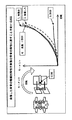
ダイナミックスタビライゼーション(非融合)器具はバック患者の危険にさらされた(機械的一体化の減少した負傷したまたは変質した)背骨を補助するためにある機能を必要とする。特に、器具は危険にさらされた背骨に対して機械的補助を提供しなければならず、それは特に補助が最も必要とされる中立領域内においてである。この“中立領域”は低い背骨剛性領域または背骨分節のモーメント−回転曲線のつま先領域を指している(図1参照)。パンジャブ語 MM。ゴエル VK、高田K。1981 生体力学分野におけるボルボ賞。“腰背骨靱帯内における生理学的張力、試験管内での生体力学研究” スパイン 7(3):192−203、1982。中立領域は通常中立姿勢周りの運動の領域の中央部分と限定され、そこでは背骨の柔らかい組織および小関節面の接合部が背骨の運動に対して最も小さい抵抗を提供する。この概念は図1内に示されているように無傷のおよび負傷した背骨の負荷−変位または動き−回転曲線上に正確に可視化されている。曲線は非直線的であり;即ち、背骨の機械的特性は角形成および/または回転量により変わることを注目されたい。もし我々が曲線のポジテイブおよびネガテイブサイドをそれぞれ湾曲および引っ張り特性を表示するものと考えると、曲線の各点における傾斜は背骨の剛性を表示することになる。図1内に見られるように、中立領域は動き領域の低剛性地域である。 Dynamic stabilization (non-fusion) devices require certain functions to assist the back patient at risk of injury (degraded or altered) with reduced mechanical integration. In particular, the instrument must provide mechanical assistance to the compromised spine, particularly in the neutral region where assistance is most needed. This “neutral region” refers to the low spine stiffness region or toe region of the spine segment moment-rotation curve (see FIG. 1). Punjabi MM. Goel VK, Takada K. 1981 Volvo Award in the field of biomechanics. “Physiological tension in the lumbar spinal ligament, biomechanical study in vitro” Spine 7 (3): 192-203, 1982. The neutral region is usually confined to the central portion of the region of motion around the neutral posture, where the soft tissue of the spine and the small articular surface joint provide the least resistance to spinal motion. This concept is accurately visualized on the load-displacement or motion-rotation curve of the intact and injured spine as shown in FIG. Note that the curves are non-linear; that is, the mechanical properties of the spine change with angulation and / or rotation. If we consider the positive and negative sides of the curve to represent curvature and tensile properties, respectively, the slope at each point of the curve will indicate the stiffness of the spine. As can be seen in FIG. 1, the neutral region is the low stiffness region of the motion region.
実験は背骨コラムの損傷後または変質により、中立領域が、動き範囲と共に、増加する(図1参照)ことを示してきた。しかしながら、中立領域は運動範囲よりもより大きく増加し、これは対応する無傷値の率として記述された時に分かる。これは中立領域が、動きの範囲よりも、背骨の負傷および不安定性のより良い物差しであることを暗示している。臨床研究はまた運動増加の範囲が低バックペインと良く関連するものではないことを見出している。従って、不安定な背骨は特に中立領域内で安定化されることを要する。ダイナミック内側スタビライゼーション器具は背骨と共に動くように可撓性を有するものでなければならず、このようにしてデイスク、小関節面、および靱帯が通常の生理学上の運動および負荷を許容し、このことはそれらの栄養物摂取を満足状態に保つ上で必要なことである。これらの器具は個々の患者および解剖学的構造の異なる物理的特性に適合しなければならず、これは個々の患者のための所望姿勢を達成するためである。 Experiments have shown that the neutral region increases with the range of motion (see FIG. 1) after spinal column damage or alteration. However, the neutral region increases more than the range of motion, which can be seen when described as the rate of the corresponding intact value. This implies that the neutral region is a better measure of spinal injury and instability than the range of motion. Clinical studies have also found that the extent of increased exercise is not well associated with low back pain. Therefore, the unstable spine needs to be stabilized, especially in the neutral region. The dynamic medial stabilization device must be flexible to move with the spine, and in this way the disc, facet, and ligament allow normal physiological movement and loading, It is necessary to keep their nutrition intake satisfactory. These instruments must adapt to different physical characteristics of the individual patient and anatomy, in order to achieve the desired posture for the individual patient.
前述のことを考慮すると、当業者は従来技術の器具の不具合を克服する背骨安定化用器具の必要性の存在を理解するであろう。本発明は背骨安定化のためにそのような装置および方法を提供するものである。 In view of the foregoing, those skilled in the art will appreciate the need for a spinal stabilization device that overcomes the deficiencies of prior art devices. The present invention provides such a device and method for spine stabilization.
従って、本発明の目的は背骨安定化のための方法を提供することである。この方法はダイナミックスタビライザーを背骨の椎骨に取り付けてダイナミックスタビライザーの取り付けられている背骨の領域に抵抗の形の機械的補助を提供することにより達成される。抵抗は、背骨が中立領域周りにある間はより大きい機械的補助が提供され、かつ背骨がその中立領域を越えて湾曲する間はより小さい機械的補助が提供されるように、供給される。 Accordingly, an object of the present invention is to provide a method for spine stabilization. This method is accomplished by attaching a dynamic stabilizer to the spine vertebra to provide a mechanical aid in the form of resistance to the spine region where the dynamic stabilizer is attached. Resistance is provided such that greater mechanical assistance is provided while the spine is around the neutral region and less mechanical assistance is provided while the spine curves beyond the neutral region.
ダイナミックスタビライザーを提供することも本発明の目的であり、上記スタビライザーは負傷した背骨の中立領域に実質的に対応する中央領域内で増量された機械的支持を提供する背骨の動きの制御の元に動く。このスタビライザーは支持アセンブリーおよび上記支持アセンブリーと協働する抵抗アセンブリーを備えている。抵抗アセンブリーは中央領域内の動き中には動きに対してより大きい抵抗を供給し、かつスタビライザーがその中央領域を越えた引き延ばし運動を受ける間は動きに対してより低い抵抗を供給するような抵抗を発生させる。 It is also an object of the present invention to provide a dynamic stabilizer, which is under the control of spinal motion to provide increased mechanical support in a central region substantially corresponding to the neutral region of the injured spine. Move. The stabilizer includes a support assembly and a resistance assembly that cooperates with the support assembly. The resistance assembly provides resistance that provides greater resistance to movement during movement within the central area and lower resistance to movement while the stabilizer is undergoing stretching motion beyond that central area. Is generated.
ピストンアセンブリーおよび上記ピストンアセンブリーと協働する抵抗アセンブリーを備えたダイナミックスタビライザーを提供することも本発明の別の目的である。上記抵抗アセンブリーは第1スプリングおよび第2スプリングにより構成され、かつ上記ピストンアセンブリーは抵抗アセンブリーをボデー部材に対して連結するための形および寸法とされている。 It is another object of the present invention to provide a dynamic stabilizer with a piston assembly and a resistance assembly that cooperates with the piston assembly. The resistance assembly includes a first spring and a second spring, and the piston assembly is shaped and dimensioned to connect the resistance assembly to the body member.
本発明の他の目的および利点は本発明のある実施例を述べている添付図面に関連して見られた時の以下の詳細な記述から明らかにされるであろう。 Other objects and advantages of the present invention will become apparent from the following detailed description when viewed in conjunction with the accompanying drawings, which describe certain embodiments of the invention.
本発明の詳細な実施例がここに開示されている。しかしながら、開示された実施例が各種形態に具体化され得る本発明の単なる例であるは理解されるべきである。従って、ここに開示されている詳細は制限されたものと解釈されるべきではなく、むしろ単に請求項の基礎として、および当業者に本発明を如何に作りかつ/または使用するかを教える基礎として解釈されるべきである。 Detailed embodiments of the present invention are disclosed herein. However, it should be understood that the disclosed embodiments are merely examples of the invention that may be embodied in various forms. Accordingly, the details disclosed herein should not be construed as limiting, but rather merely as a basis for claims and as a basis for teaching one of ordinary skill in the art how to make and / or use the present invention. Should be interpreted.
図2、3a−eおよび図4において、背骨安定化のための方法および装置が開示されている。本発明の好ましい実施例によると、背骨安定化方法は隣接椎骨12、14の間に内側ダイナミック背骨スタビライザー10を装着することにより、かつダイナミック背骨スタビライザー10が装着される背骨領域に対して弾性抵抗の形の機械的補助を提供することにより達成される。この弾性抵抗は変位機能として適用されて背骨がその中立領域内にある間はより大きい機械的補助が提供されかつ背骨が中立領域を越えて曲がる間はより小さい機械的補助が提供される。弾性抵抗なる用語が本明細書の本体を通して使用されているが、他形式の抵抗も本発明の精神から離れることなく採用され得る。
2, 3a-e and FIG. 4, a method and apparatus for spine stabilization is disclosed. According to a preferred embodiment of the present invention, the spine stabilization method provides elastic resistance by attaching the inner
当業者は確かに評価し、かつ上述されているように、“中立領域”は低い背骨剛性領域または背骨分節(図2参照)のモーメント−回転曲線のつま先領域を述べているものと理解される。即ち、中立領域は背骨分節の中立休止位置周りの不正確な領域でそこには椎間運動に対する最小抵抗の存在する領域を述べているものと考え得る。中立領域の範囲は背骨安定化の決定における主たる重要性であると考えられる。パンジャブ語、MM“背骨の安定化システム。パートII。中立領域および不安定化仮説”。ジェイ スパイナル デイスオーダー 1992;5(4):390−397。 One skilled in the art will certainly appreciate and, as described above, “neutral region” is understood to describe the low spine stiffness region or the toe region of the spine segment (see FIG. 2) moment-rotation curve. . That is, it can be considered that the neutral region is an inaccurate region around the neutral rest position of the spine segment and describes the region where the minimum resistance to intervertebral motion exists. The range of the neutral region is considered to be of primary importance in the determination of spine stabilization. Punjabi, MM "Spine stabilization system. Part II. Neutral region and destabilization hypothesis". Jay Spinal Day Order 1992; 5 (4): 390-397.
実際に、発明者は以前は“椀内のボール”類推理論の使用による背骨安定化と協働する負荷変位曲線を記述してきた。この類推によると、椀の形は背骨の安定化を表示する。より深い椀はより安定した背骨を提供し、一方、より浅い椀はより安定性の少ない背骨を意味する。発明者は以前は背骨の負傷のない者に対しては通常範囲の動きを伴う時に通常の中立領域(その運動範囲では椎骨内に最小の抵抗がある)があり、かつ順番に、背骨の痛みは無いと仮定していた。この例においては、椀は深過ぎもせず浅過ぎもしていない。しかしながら、解剖学的構造部分に負傷が起こると、背骨コラムの中立領域が増しかつ椀が大距離にわたり自由に動く。この類推により、椀はより浅くかつボールはより安定化され、かつその結果として、痛みはこの拡大された中立領域からもたらされる。 Indeed, the inventor has previously described a load displacement curve that cooperates with spine stabilization through the use of the “ball in cage” analogy theory. According to this analogy, the shape of the heel indicates spine stabilization. A deeper heel provides a more stable spine, while a shallower heel means a less stable spine. The inventor previously had a normal neutral region (with minimal resistance within the vertebrae in that range of motion) when accompanied by a normal range of movement for those who have not had a spinal injury, and in turn, spinal pain It was assumed that there was no. In this example, the reed is neither too deep nor too shallow. However, when an anatomy is injured, the neutral region of the spine column increases and the heel moves freely over a large distance. By this analogy, the wrinkles are shallower and the ball is more stabilized, and as a result, pain comes from this enlarged neutral region.
一般に、茎ねじ16、18はダイナミック背骨スタビライザーを背骨の椎骨12、14に対して取り付け、これには当業者に知られている良く許容されかつありふれた外科手続が使用される。好ましい実施例に従い、かつ当業者が確かに評価するように、1対の対向するスタビライザーが背骨に加えられる負荷をバランスさせるために通常使用される(図3c参照)。ダイナミック背骨スタビライザー10は後痛患者の傷付けられた(負傷したおよび/または変質された)背骨を助け、かつ彼女/彼の日常活動の実施を助ける。ダイナミック背骨スタビライザー10はそれを、制御された抵抗を背骨運動特に中立領域内の中立姿勢周りに与えることにより行う。背骨が前方へ曲がる(湾曲する)とスタビライザー10は引っ張られ(図3d参照)かつ背骨が後方へ曲がる(延びる)とスタビライザーは圧縮される(図3e参照)。
In general, the pedicle screws 16,18 attach a dynamic spine stabilizer to the
ダイナミック背骨スタビライザー10により提供される変位に対する抵抗は非線形であり、個々の中立領域に対応するようにその中央領域内で最大であり;これは、スタビライザー10の中央領域が背骨を支持する上で高いレベルの機械的補助を提供していることである。個体が中立領域を越えて動くと、抵抗面の増加はより穏やかなレベルへ減少する。その結果として、個体は中立領域内で動いている間は動きに対してより大きい抵抗(またはより大きい増加抵抗)に遭遇する。
The resistance to displacement provided by the
ダイナミック背骨スタビライザー10の中央領域、そこでは背骨スタビライザー10が動きに対して最大の抵抗を提供する動きの領域であるが、その中央領域は個々の患者の中央領域に適合するように外科手術時に調整可能である。ダイナミック背骨スタビライザー10により提供される動きに対する抵抗は手術前および手術中に調整可能である。これはダイナミック背骨スタビライザー10の機械的特性の調整を助けて個々の患者の危険にさらされている背骨に適合させ得る。ダイナミック背骨スタビライザーの長さも手術中に調整可能であり、これにより個々の患者の解剖学的構造に適合させかつ所望の背骨姿勢を達成させ得る。ダイナミック背骨スタビライザー10は手術前に外科手法により再調整されて、その中央領域を患者の変えられたニーズに適応させ得る。
The central region of the
ボールジョイント20、22はダイナミック背骨スタビライザー10を茎ねじ16、18に連結する。ダイナミック背骨スタビライザー10および茎ねじ16、18の接合部は自由でありかつ回転自在である。従って、第1に、背骨には曲げおよび捩りの全ての物理的動きが許容され、かつ第2に、ダイナミック背骨スタビライザー10および茎ねじ16、18は有害な曲げおよび捩り力、またはモーメントから保護されている。ボールジョイントは本発明の好ましい実施例に従って開示されているが、他の連結構造も本発明の精神から離れることなく利用され得る。
Ball joints 20, 22 connect
スタビライザーの両端にボールジョイント20、22があるので、曲げモーメントは背骨からスタビライザー10へ伝達され得ない。更に、重要なことは、スタビライザー10上に作用する力はその中のスプリング30、32によるもののみであることである。これらの力は単に背骨運動により決定されるようなスタビライザー10の延びおよび圧縮に依存している。要約すると、スタビライザー10は単に両ばね力を見せる。人が重い荷物を運びまたは持ち上げる時のような、背骨上への大きい負荷に拘わらず、スタビライザー10へくる負荷はスタビライザー10内で発生する力のみであり、これらは背骨運動の結果でありかつ背骨負荷の結果ではない。スタビライザー10は、従って、背骨の高負荷に耐えることなく独特に助けることができ、広範囲の設計の選択肢を許容する。
Since there are ball joints 20 and 22 at both ends of the stabilizer, the bending moment cannot be transmitted from the spine to the
また本スタビライザー10における茎ねじ16、18への負荷は従来の茎ねじ固定器具におけるのと全く相違している。これはボールジョイントねじ接続器部分で純粋な軸方向の力に直動させる。この機構は従来技術の茎ねじ混合システムと比べて茎ねじ16、18上への曲げモーメントを非常に低減する。ボールジョイント20、22により、茎ねじ16、18内の曲げモーメントはボールジョイント20、22の部分でゼロであり、かつそれは茎ねじ16、18の先端側へ向かい増加する。典型的な従来の茎ねじ固定器具における故障頻発箇所である茎ねじ−骨接続器領域は、最も応力の少ない場所であり、かつ従って破損しにくい。要するに、茎ねじ16、18は、本発明と共に使用されると、顕著に少ない負荷を負い、かつ一般的な茎ねじより顕著に少ない応力下に配置される。
The load on the pedicle screws 16 and 18 in the
図2には、健康な背骨のためのモーメント−回転曲線が本スタビライザー10付きの状態で示されている。この曲線は健康な背骨の中立領域で遭遇された動きに対する低い抵抗を示している。しかしながら、背骨が負傷を受けると、この曲線は中立領域の拡大により立証されているように(図1参照)変わり、かつ背骨は不安定になる。
In FIG. 2, the moment-rotation curve for a healthy spine is shown with the
本発明の好ましい実施例に従うと、背骨の負傷を受けた人は中立領域内で増加された機械的抵抗を加えることにより最も良好に処置される。背骨が中立領域を越えると、必要な機械的抵抗は減少しかつより穏やかになる。特に、かつ図3aにおいて、本発明により企図された支持概観図(プロフィール)が開示されている。 According to a preferred embodiment of the invention, a person who has suffered a spinal injury is best treated by applying increased mechanical resistance in the neutral region. As the spine goes beyond the neutral zone, the required mechanical resistance decreases and becomes milder. In particular, and in FIG. 3a, a support overview (profile) contemplated by the present invention is disclosed.
3個の異なる概観図が図3a内に示されている。開示されている概観は単なる例示的なものでありかつ中立領域内における可能な所要支持量を表示しているものである。プロフィール1は中立領域内で大きい補助を要する個体の例でありかつスタビライザーの中央領域は従って大きい変位上に高レベルの抵抗を提供することにより増加されている;プロフィール2は中立領域内で少ない補助が要求されている個体の例でありかつスタビライザーの中央領域は従ってより制限された範囲の変位上に増加された抵抗を提供することによりより穏やかであり;かつプロフィール3は中立領域内に僅かに大きい補助のみが要求されている例でありかつスタビライザーの中央領域は従って変位のより小さい領域のみに増加された抵抗を提供することにより低減されている。
Three different overviews are shown in Figure 3a. The disclosed overview is merely exemplary and displays possible required support in the neutral region. Profile 1 is an example of an individual that requires a large amount of assistance in the neutral region and the central region of the stabilizer is thus increased by providing a high level of resistance over large displacements; Profile 2 is less in the neutral region Is an example of an individual that is required and the central region of the stabilizer is therefore more gentle by providing increased resistance over a more limited range of displacement; and
当業者であれば確かに分かるように、所要の機械的補助および中立領域の範囲は個体より個体へと変化するであろう。しかしながら、本発明の基本的教義は残され;即ち、背骨の不安定さを被っている個体のためのより大きい補助は個体の中立領域内で要求される。この補助は個体の中立領域内およびダイナミック背骨スタビライザー10の中央領域内で提供されるより大きい抵抗の形で提供される。
As will be appreciated by those skilled in the art, the required mechanical assistance and range of neutral regions will vary from individual to individual. However, the basic doctrine of the present invention remains; that is, greater assistance for individuals suffering from spinal instability is required within the neutral region of the individual. This assistance is provided in the form of greater resistance provided in the neutral region of the individual and in the central region of the
本発明により開発されたダイナミック背骨スタビライザー10は開示された支持プロフィールに従って機械的抵抗を提供する。更に、本スタビライザー10は同芯スプリング構造により調整可能性を提供する。
The
より詳細には、ダイナミック背骨スタビライザー10は危険にさらされている背骨に対して変位に対する増加された形の補助(好ましい実施例によるスプリングにより提供される)を提供し、それは背骨が中立姿勢からいずれかの生理学上の方向に動くときに行われる。上述のように、本発明によるダイナミック背骨スタビライザー10により提供される力−変位関係は非直線的であり、背骨の中立領域周りおよびスタビライザーの中央領域でより大きい増量抵抗、およびダイナミック背骨スタビライザー10の中央領域を越えた範囲での少ない増量抵抗付きで、これらは個体が中立領域を越えて動く際に付けられる(図3a参照)。
More particularly, the
引っ張りおよび圧縮中に加えられる力に対する本スタビライザーの関係は更に図3aに関連して示されている。上述のように、本スタビライザーの特性は非直線的である。負荷−変位曲線は3個の領域:張力、中央および圧縮である。もしK1およびK2がそれぞれ張力および圧縮領域内における剛性を画定しているとすると、本スタビライザーは中央領域の高い剛性が“K1+K2”となるように設計される。より詳細には後述されるようにスタビライザー10の予圧により、中央領域の幅および、従って高剛性の領域は調整可能である。
The relationship of the present stabilizer to the force applied during tension and compression is further illustrated in connection with FIG. 3a. As described above, the characteristics of the present stabilizer are non-linear. The load-displacement curve is in three regions: tension, center and compression. If K1 and K2 define stiffness in the tension and compression regions, respectively, this stabilizer is designed so that the high stiffness in the central region is “K1 + K2.” More specifically, the width of the central region and thus the region of high rigidity can be adjusted by preloading the
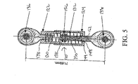
図4において、本発明によるダイナミック背骨スタビライザー10が開示されている。ダイナミック背骨スタビライザー10はハウジング20の形の支持アセンブリーを備えており、上記ハウジングは第1ハウジング部材22および第2ハウジング部材24で構成されている。第1ハウジング部材22および第2ハウジング部材24は第1ハウジング部材22の開放端部26上に形成された外側ねじおよび第2ハウジング部材24の開放端部28上に形成された内側ねじを介して入れ子式に接続されている。このようにして、ハウジング20は第1ハウジング部材22を第2ハウジング部材24内に螺合することにより完成されている。そのように、かつ以下に詳述されるように、第1ハウジング部材22および第2ハウジング部材24の間の相対距離は容易に調整することができ、それはハウジング20内に収容されている第1スプリング30および第2スプリング32の圧縮を調整するためである。スプリングが本発明の好ましい実施例により採用されているが、他の弾性部材も本発明の精神から離れることなく採用され得る。ピストンアセンブリー34が第1スプリング30および第2スプリング32を第1および第2ボールジョイント36、38に連結している。第1および第2ボールジョイント36、38はそれぞれの椎骨12、14から延びている茎ねじ16、18に対して選択的に取り付けるために形成設計されている。
In FIG. 4, a
第1ボールジョイント36はねじ付き螺合部材40を介して第1ハウジング部材20の閉塞端部38に固着され、上記部材40は第1ハウジング部材22の閉塞端部38内に形成されている開口42内に形成されているねじと結合するように形および寸法が定められている。このようにして、第1ボールジョイント36は第1ハウジング部材22の閉塞端部38を実質的に閉塞している。ダイナミック背骨スタビライザー10の長さは第1ボールジョイント36を回して第1ハウジング部材22および第1ボールジョイント36の螺合部材40の間の重複量を調整することにより容易に調整され得る。当業者なら確かに察知するように、第1ハウジング部材22および第1ボールジョイント36の螺合部材40の間の螺合が好ましい実施例に従い開示されているが、他の結合構造も本発明の精神から離れることなく採用され得る。
The first ball joint 36 is fixed to the
第2ハウジング部材24の閉塞端部44はその中に形成された開口48を有するキャップ46を備えている。以下により詳細に記述されるように、開口48はそれを通してピストンアセンブリー34からのピストンロッド50が通過するように形状および寸法が定められている。
The
ピストンアセンブリー34はピストンロッド50;第1および第2スプリング30、32;および保持用ロッド52を備えている。ピストンロッド50はストップナット54および拡大ヘッド56をその第1端部58に備えている。拡大ヘッド56はピストンロッド50に剛直に連結されておりかつガイド孔60を備え、その孔を通して保持ロッド52が本ダイナミック背骨スタビライザー10の動作中に延びている。そのように、拡大ヘッド56は第2ボールジョイント38がボールジョイント36側へまたはそれから離れる側へ動かされる間、保持ロッド52に沿いガイドされる。以下により詳細に記述されるように、拡大ヘッド56は第1スプリング30と係合してダイナミック背骨スタビライザー10が延ばされかつ背骨が湾曲状に動かされると抵抗を創生する。
The
ストップナット54はピストンロッド50上にそれと自由な相対移動ができるようにフィットしている。しかしながら、ストップナット54の第1ボールジョイント36側への動きは保持ロッド52により阻止されており、このロッドはストップナット54を支持しかつストップナット54の第1ボールジョイント36側への動きを阻止している。以下により詳細に記述されるように、ストップナット54は第2スプリング32と係合してダイナミック背骨スタビライザー10が圧縮されかつ背骨が伸長側へ動かされると抵抗を創生する。
The stop nut 54 is fitted on the piston rod 50 so that it can freely move relative thereto. However, the movement of the stop nut 54 toward the first ball joint 36 is prevented by the holding rod 52, which supports the stop nut 54 and prevents the stop nut 54 from moving toward the first ball joint 36. is doing. As described in more detail below, the stop nut 54 engages the second spring 32 to create resistance when the
ピストンロッド50の第2端部62は第2ハウジング部材24の閉塞端部44の部分で開口48から延びており、かつ第2ボールジョイント38の螺合部材64に対して取り付けられている。ピストンロッド50の第2端部62は第2ボールジョイント38の螺合部材64に対して螺合連結されている。当業者なら確かに察知するであろうように、ピストンロッド50の第2端部62および第2ボールジョイント38の螺合部材64の間の螺合が好ましい実施例に従い開示されているが、他の結合構造も本発明の精神から離れることなく採用され得る。
The second end 62 of the piston rod 50 extends from the
上に簡略に述べたように、第1および第2スプリング30、32はハウジング20内に保持されている。特に、第1スプリング30はピストンロッド50の拡大ヘッド56および第2ハウジング部材24のキャップ46の間に延びている。第2スプリング32は第2ボールジョイント38の螺合部材64の末端およびピストンロッド50のストップナット54の間で延びている。第1および第2スプリング30、32により供給されている予め負荷された力がピストンロッドをハウジング20内で静止状態に保持して、ピストンロッドは背骨の伸長および湾曲の何れの間でも動き得る。
As briefly described above, the first and
使用中に、椎骨12、14が湾曲状に動かされかつ第1ボールジョイント36が第2ボールジョイント38から離れる方向に引かれると、ピストンロッド50はハウジング24内で第1スプリング30により適用される力に抗して引かれる。特に、ピストンロッド50の拡大ヘッド56は第2ハウジング部材24の閉塞端部44側へ動かされる。この動きは第1スプリング30を圧縮し、背骨の動きに対する抵抗を創生する。第2スプリング32に付いては、第2スプリング32はピストンロッド50と共に第2ボールジョイント38から離れるように動かされる。椎骨が中立領域内で湾曲状に動くと、第2スプリング32の高さは増加され、そらし力は減少し、かつその結果として器具の動きに対する抵抗は増加する。この機構を通して、背骨が初期位置から湾曲状に動くとスプリング30およびスプリング32の双方が器具の反りに抵抗し、それはスプリング(即ち、第1スプリング30)内の負荷の増加によりまたは動きを補助する負荷の減少の何れかによる。
In use, the piston rod 50 is applied within the
しかしながら、背骨が伸長状態にあり、かつ第2ボールジョイント38が第1ボールジョイント36側へ動かされる時、第2ボールジョイント38の螺合部材64はストップナット54側へ動き、このナットはピストンロッド50が第1ボールジョイント36側へ動く時に保持ロッド52により当初位置に保持されている。この動きは第2スプリング32の圧縮を起こし、即ち第2スプリングは第2ボールジョイント38の螺合部材64およびストップナット54の間に保持されて、ダイナミック背骨スタビライザー10の動きに対する抵抗を創生する。第1スプリング30に付いては、第1スプリング30はキャップ46および拡大ヘッド56の間に支持され、かつ椎骨が中立領域内で伸長状態となると、第2スプリング30の高さは増し、圧縮力は減り、かつ結果において器具の動きに対する抵抗は増加する。この機構を通して、背骨が中立位置から伸長状態に動くとスプリング32およびスプリング30の双方が器具の圧縮に直接的に抵抗し、それはスプリング(即ち、第2スプリング32)内の負荷の増加によりまたは動きを補助する負荷(即ち、第1スプリング30)の減少の何れかによる。
However, when the spine is in an extended state and the second ball joint 38 is moved to the first ball joint 36 side, the screw member 64 of the second ball joint 38 moves to the stop nut 54 side, and this nut is a piston rod. When 50 moves to the first ball joint 36 side, it is held in the initial position by the holding rod 52. This movement causes compression of the second spring 32, that is, the second spring is held between the threaded member 64 of the second ball joint 38 and the stop nut 54 to create resistance to movement of the
2個の同芯的に配置された弾性スプリング30、32の使用に基づき、本発明に従い開示されているように、図2内に示されているような補助(力)プロフィールが本ダイナミック背骨スタビライザー10により提供される。即ち、第1および第2スプリング30、32は、ダイナミック背骨スタビライザー10がスタビライザーの中央領域内に配置された時、大きい弾性力を提供するように協働する。しかしながら、ひとたび第1ボールジョイント36および第2ボールジョイント38の間の間隔がスタビライザー10の中央領域および個々の背骨の動きの中立領域を越えて延びると、動きに対する増量抵抗が実質的に低減され、これは個々が中立領域内ではもはや実質的な補助を必要としないからである。これはここに記述されている器具の中央領域のセッテイングにより達成される。力−変位曲線の中央領域は曲線の領域であり、その領域は両方のスプリングが上述のように器具内で作動している時を意味している。背骨の動きが中立領域外でありかつ関連する器具の伸長または圧縮が中立領域外になると、伸長していたスプリングはその自由長さに達する。当業者なら誰でも察知するように、自由長さは力が加えられていないスプリングの長さである。この機構においては、中央領域(ここでは双方のスプリングが動きに抵抗するように作動する)外の器具の動きに対する抵抗は一つのスプリングの抵抗のみに依存しそのスプリングは;湾曲状態におけるスプリング30または伸長状態におけるスプリング32の何れかである。
Based on the use of two concentrically arranged
簡潔に上述したように、ダイナミック背骨スタビライザー10は第1ハウジング部材22を第2ハウジング部材24に対して回すことにより調整される。この動きは第1ハウジング部材22および第2ハウジング部材24の間の間隔を変え、これは第1および第2スプリング30、32に掛けられる予圧を最終的に変えるためである。この予圧変更は本ダイナミック背骨スタビライザー10の抵抗プロフィールを変え、これは図3aのプロフィールに示されているものから予圧により増加されたもの(図3aのプロフィール1参照)への移行であり、そこでは有効領域が拡大されて第1および第2スプリング30、32が同時に作動する。スタビライザーの中央領域におけるこの増加された幅は背骨のより大きい動き領域にわたるより高い剛性に関連している。この効果は図3aのプロフィール3で立証されているように逆にもされ得る。
As briefly described above, the
本ダイナミック背骨スタビライザー10は支持を要する椎骨部分から延びている茎ねじ16、18に対して装着される。ダイナミック背骨スタビライザー10の外科的装着中、スタビライザーの中央領域の大きさは個々の患者のために調整可能であり、それは外科医の判断および/または不安定性計測器具による計量により行われる。ダイナミック背骨スタビライザー10のこの調整可能プロフィールは本発明の好ましい実施例により得られた3個の説明用プロフィール内に例示されている(図2;器具の中央領域の幅を注目されたい)。
The
手術前に、ダイナミック背骨スタビライザー10の第1および第2の弾性スプリング30、32はより広い範囲の背骨不安定性に対応するように異なるセットに取り換え得る。図3b内に表示されているように、プロフィール2bは図3bのプロフィール2a内に示されているものに比べてより剛性の高いスプリングセットで作られる力−変異曲線を表示している。
Prior to surgery, the first and second
手術中に、ダイナミック背骨スタビライザー10の長さは第1ボールジョイント36の螺合部材40を回すことにより調整可能であり、異なる患者の解剖学的構造および所望の背骨の姿勢に適合させるようにスタビライザー10を延ばす。手術前に、ピストンロッド50はより広い範囲の解剖学的多様性に対応するように取り換え得る。
During surgery, the length of the
本ダイナミック背骨スタビライザー10はその負荷−変位関係のみでテストされている。張力を加える時、ダイナミック背骨スタビライザー10は予め画定された変位に達するまでの増加した抵抗を表示し、器具がその一杯まで伸長した位置に達するまで増加抵抗の減少率により従動される。圧縮に晒された時は、ダイナミック背骨スタビライザー10は予め画定された変位に達するまでの増加した抵抗を表示し、器具がその一杯まで圧縮された位置に達するまで増加抵抗の減少率により従動される。従って、ダイナミック背骨スタビライザー10は負荷−変位曲線を表示し、その曲線は非直線状であり中立姿勢周りで変位に対する最高の抵抗を提供する。この特性は危険にさらされた背骨の負荷−変位曲線の平常化を助ける。
The
図5に関する、別の実施例構造において、スタビライザー110は直列スプリング配置に構成され得る。この実施例に従うと、ハウジング120は第1および第2のハウジング部材122、124で構成され、これらは調整を許容するためのねじで連結されている。第1ボールジョイント136は第1ハウジング部材122から延びている。第2ハウジング部材124は開口148を備え、これを通してピストンロッド150の第2端部162が延びている。ピストンロッド150の第2端部162は第2ボールジョイント138に取り付けられている。第2ボールジョイント138はピストンロッド150上に固着されている。
In another example configuration with respect to FIG. 5, the stabilizer 110 may be configured in a series spring arrangement. According to this embodiment, the housing 120 is composed of first and
ピストンロッド150はその第1端部158に拡大ヘッド156を備えている。第1および第2スプリング130、132はそれぞれ拡大ヘッド156および第1および第2のハウジング部材122、124の閉塞端部138、144の間に装着されている。このように、スタビライザー110は以前の実施例のために記述されたのと同じ機械的原理を使用して膨張および圧縮の双方に対する抵抗を提供している。
The piston rod 150 includes an
この別の実施例による抵抗プロフィールの調整は第1ハウジング部材122の第2ハウジング部材124に対する回転により達成される。この方法による回転はスタビライザー110により提供される高い抵抗の中央領域を変える。前述のように1または双方のスプリングが交換されて力−変位曲線の傾斜を2または3領域のそれぞれで変え得る。
Adjustment of the resistance profile according to this alternative embodiment is achieved by rotation of the
如何にスタビライザー10、110が危険にさらされた背骨(増加された中立領域)を補助するかを説明するためにモーメント−回転曲線(図6)を観察されたい。4個の曲線が示されている:1.無傷の、2.負傷した、3.スタビライザーおよび、4.負傷した+スタビライザー。これらは、それぞれ、無傷の背骨のモーメント−回転曲線、負傷した背骨、スタビライザー単独、およびスタビライザープラス負傷した背骨、この曲線が無傷曲線に近いことを注目されたい。このようにして、中立姿勢周りの動きに対してより大きい抵抗を提供するスタビライザーは、背骨の不安定性を補償するのに理想的に適している。
Observe the moment-rotation curve (FIG. 6) to illustrate how the
上述のダイナミック背骨スタビライザーに加えて、他の補完的な器具が考えられる。例えば、リンク器具が左および右スタビライザーユニット結合のために提供されて軸回転および横曲げにおける追加の安定性提供を助け得る。このリンク器具はダイナミック背骨スタビライザーの補足部材であり得る。これは個々の患者の所望により適用され得る。更に、背骨スタビリテイー計測器具も利用され得る。計測器具は手術時における各背骨レベルの安定性を計測し得る。この器具は手術中に1対の隣接背骨要素を接続し、危険にさらされているかおよび危険にさらされていないレベルで各レベルの安定性を計測する。隣接した負傷したレベルに対する無傷レベルの安定性計測値は器具の適当な調整の決定に使用され得る。更に、負傷した背骨のスタビリテイー計測値は通常の負傷していない背骨のスタビリテイーの作表されたデータベースを参照することにより器具の調整に使用可能である。器具は単純かつ丈夫にされ得るので、外科医は手術下において最も簡単な方法で情報が提供され得る。 In addition to the dynamic spine stabilizer described above, other complementary devices are contemplated. For example, a linkage device may be provided for left and right stabilizer unit coupling to help provide additional stability in axial rotation and lateral bending. This linking device may be a supplementary member of the dynamic spine stabilizer. This can be applied as desired by the individual patient. In addition, a spine stability measuring instrument may be utilized. The measuring instrument can measure the stability of each spine level during surgery. The instrument connects a pair of adjacent spine elements during surgery and measures each level of stability at the level at risk and at risk. Intact level stability measurements relative to adjacent injured levels can be used to determine the proper adjustment of the instrument. In addition, injured spine stability measurements can be used to adjust the instrument by referring to a tabulated database of normal non-injured spine stability. Since the instrument can be made simple and rugged, the surgeon can be provided with information in the simplest way under surgery.
本発明により使用され所望の力プロフィール曲線を達成するためのスプリングの選択はスプリングにより作られる力を制御する基本的物理法則により制御される。特に、上述されかつ図3a内に示されている力プロフィールは本スタビライザーの独特な設計により達成される。 The selection of a spring to achieve the desired force profile curve used by the present invention is controlled by the basic physical laws that control the force created by the spring. In particular, the force profile described above and shown in FIG. 3a is achieved by the unique design of the present stabilizer.
第1に、スタビライザーはスタビライザー内の2個のスプリングが共に圧縮タイプであっても圧縮および引っ張りの双方の機能を果たす。第2に、中央領域内でスタビライザーにより提供されるより高い剛性(K1+K2)は予圧の存在によるものである。予圧が存在する時には両スプリングが共に作動するように作られている。スタビライザーは引っ張られまたは圧縮されるので、一つのスプリング内では力は増しかつ他方では減少する。減少した力がゼロ値に達すると、この力に対応するスプリングはもはや機能せず、このようにしてスタビライザー機能は低下し、図7aおよび7b内に示されているダイヤグラムを含むエンジニアリング解析は以下に提供されている(解析は特に図5内に開示されている実施例に関連しているが、当業者はそれが本発明により開示された全ての実施例に適用され得る方法であることを察知するであろう)。 First, the stabilizer performs both compression and tension functions even if the two springs in the stabilizer are both compression types. Secondly, the higher stiffness (K1 + K2) provided by the stabilizer in the central region is due to the presence of preload. Both springs are made to work together when preload is present. As the stabilizer is pulled or compressed, the force increases in one spring and decreases on the other. When the reduced force reaches a zero value, the spring corresponding to this force no longer functions and thus the stabilizer function is reduced and the engineering analysis including the diagrams shown in FIGS. 7a and 7b is as follows: (The analysis is particularly relevant to the embodiment disclosed in FIG. 5, but one skilled in the art will recognize that it is a method that can be applied to all embodiments disclosed by the present invention. Will do).
Foはスタビライザー内の予圧であり、上述されているようにハウジングのボデー長さを短縮することにより導入される。
K1およびK2はそれぞれスタビライザーの引っ張りおよび圧縮中に有効な圧縮スプリングの剛性係数である。
FおよびDはそれぞれスタビライザーのボデーに関連したスタビライザーのデイスクの力および変位である。
デイスク上における力の合計はゼロである。従って
F+(F0―DXK2)―(F0+DXK1)=0、および
F=DX(K1+K2)
中央領域(CZ)幅については(図3a参照)
引っ張りサイドでのCZTは:
CZT=FO/K2
圧縮サイドでのCZCは:
CZC=FO/K1
Fo is the preload in the stabilizer and is introduced by shortening the body length of the housing as described above.
K 1 and K 2 are the compression spring stiffness coefficients effective during stabilizer tension and compression, respectively.
F and D are the stabilizer disk forces and displacements associated with the stabilizer body, respectively.
The total force on the disk is zero. Therefore
F + (F 0 −D X K 2 ) − (F 0 + D X K 1 ) = 0, and
F = D X (K 1 + K 2 )
For the central area (CZ) width (see FIG. 3a)
CZ T on the pull side is:
CZ T = F O / K 2
CZ C on the compression side is:
CZ C = F O / K 1
当業者なら確かに察知するであろうように、本発明の基礎をなす概念は他の医療手順に適用され得る。そのように、これらの概念は本発明の範囲から離れることなく背骨治療を越えて利用され得る。 As one skilled in the art will certainly recognize, the concepts underlying the present invention can be applied to other medical procedures. As such, these concepts can be utilized beyond spine treatment without departing from the scope of the present invention.
好ましい実施例が示されかつ記述されてきたが、そのような開示により本発明を限定する意図はなく、むしろ、添付の請求の範囲に限定されているように、本発明の精神および範囲内に入る全ての修正および代わりの構造をカバーすることが意図されていることは理解されるであろう。 While preferred embodiments have been shown and described, it is not intended that the invention be limited by such disclosure, but rather be within the spirit and scope of the invention as limited by the appended claims. It will be understood that it is intended to cover all modifications and alternative constructions that come in.
Claims (24)
背骨の椎骨に対してダイナミックスタビライザーを固着し;
スタビライザーが取り付けられる背骨の領域に対して抵抗の形の機械的補助を提供し、そこでは背骨がその中立領域周りにある間はより大きい機械的補助が提供されかつ背骨がその中立領域を越えて曲がる間はより小さい機械的補助が提供されるように抵抗が供給される、方法。 A method for spinal stabilization that includes the following steps:
Anchoring the dynamic stabilizer to the spine vertebrae;
Provides mechanical assistance in the form of resistance to the region of the spine to which the stabilizer is attached, where greater mechanical assistance is provided while the spine is around its neutral region and the spine extends beyond its neutral region A method in which resistance is provided so that less mechanical assistance is provided during bending.
支持アセンブリー;
支持アセンブリーと協働する抵抗アセンブリー、そこで抵抗アセンブリーが中央領域内の動き中により大きい抵抗を供給しかつスタビライザーがその中央領域を越えた延長運動を行う間により低い抵抗を供給するために抵抗を発生する抵抗アセンブリーを包含している、スタビライザー。 A dynamic stabilizer moves under the control of spinal motion that provides increased mechanical support in a central region substantially corresponding to the neutral region of the injured spine, which stabilizer:
Support assembly;
Resistor assembly that cooperates with the support assembly, where the resistor assembly provides greater resistance during movement within the central region and generates resistance to provide lower resistance while the stabilizer performs an extended motion beyond that central region A stabilizer that includes a resistance assembly.
ピストンアセンブリー;および
ピストンアセンブリーと協働する抵抗アセンブリーを包含し、そこで抵抗アセンブリーが第1スプリングおよび第2スプリングで構成されかつピストンアセンブリーが抵抗アセンブリーをボデー部材に対して連結するための形状と寸法にされている、スタビライザー。 Dynamic stabilizer, which is:
A piston assembly; and a resistance assembly cooperating with the piston assembly, wherein the resistance assembly comprises a first spring and a second spring, and the piston assembly is configured to connect the resistance assembly to the body member Stabilizer that is dimensioned with.
24. The stabilizer of claim 23, wherein the relative distance between the first housing member and the second housing member can be easily adjusted for the purpose of preload adjustment on the first and second springs.
Applications Claiming Priority (4)
| Application Number | Priority Date | Filing Date | Title |
|---|---|---|---|
| US46741403P | 2003-05-02 | 2003-05-02 | |
| US50672403P | 2003-09-30 | 2003-09-30 | |
| PCT/US2004/013684 WO2004098452A2 (en) | 2003-05-02 | 2004-04-30 | Dynamic spine stabilizer |
| US10/835,109 US7029475B2 (en) | 2003-05-02 | 2004-04-30 | Spinal stabilization method |
Publications (1)
| Publication Number | Publication Date |
|---|---|
| JP2006525098A true JP2006525098A (en) | 2006-11-09 |
Family
ID=33437070
Family Applications (1)
| Application Number | Title | Priority Date | Filing Date |
|---|---|---|---|
| JP2006514238A Pending JP2006525098A (en) | 2003-05-02 | 2004-04-30 | Dynamic spine stabilizer |
Country Status (11)
| Country | Link |
|---|---|
| US (5) | US7029475B2 (en) |
| EP (1) | EP1622526B1 (en) |
| JP (1) | JP2006525098A (en) |
| KR (2) | KR100859827B1 (en) |
| AT (1) | ATE499889T1 (en) |
| AU (1) | AU2004235772B2 (en) |
| BR (1) | BRPI0410697A (en) |
| CA (1) | CA2524145A1 (en) |
| DE (1) | DE602004031604D1 (en) |
| ES (1) | ES2387420T3 (en) |
| WO (1) | WO2004098452A2 (en) |
Cited By (2)
| Publication number | Priority date | Publication date | Assignee | Title |
|---|---|---|---|---|
| JP2009538159A (en) * | 2006-05-08 | 2009-11-05 | ウォーソー・オーソペディック・インコーポレーテッド | Flexible spinal connection element for bearing loads |
| JP2011509137A (en) * | 2008-01-11 | 2011-03-24 | 崔 吉運 | Flexible rod for spinal fixation |
Families Citing this family (388)
| Publication number | Priority date | Publication date | Assignee | Title |
|---|---|---|---|---|
| FR2812185B1 (en) | 2000-07-25 | 2003-02-28 | Spine Next Sa | SEMI-RIGID CONNECTION PIECE FOR RACHIS STABILIZATION |
| FR2812186B1 (en) | 2000-07-25 | 2003-02-28 | Spine Next Sa | FLEXIBLE CONNECTION PIECE FOR SPINAL STABILIZATION |
| US7833250B2 (en) | 2004-11-10 | 2010-11-16 | Jackson Roger P | Polyaxial bone screw with helically wound capture connection |
| US6579319B2 (en) | 2000-11-29 | 2003-06-17 | Medicinelodge, Inc. | Facet joint replacement |
| US20050080486A1 (en) | 2000-11-29 | 2005-04-14 | Fallin T. Wade | Facet joint replacement |
| US6565605B2 (en) | 2000-12-13 | 2003-05-20 | Medicinelodge, Inc. | Multiple facet joint replacement |
| US6419703B1 (en) | 2001-03-01 | 2002-07-16 | T. Wade Fallin | Prosthesis for the replacement of a posterior element of a vertebra |
| US7090698B2 (en) | 2001-03-02 | 2006-08-15 | Facet Solutions | Method and apparatus for spine joint replacement |
| GB0107708D0 (en) | 2001-03-28 | 2001-05-16 | Imp College Innovations Ltd | Bone fixated,articulated joint load control device |
| US10729469B2 (en) | 2006-01-09 | 2020-08-04 | Roger P. Jackson | Flexible spinal stabilization assembly with spacer having off-axis core member |
| US7862587B2 (en) | 2004-02-27 | 2011-01-04 | Jackson Roger P | Dynamic stabilization assemblies, tool set and method |
| US8292926B2 (en) | 2005-09-30 | 2012-10-23 | Jackson Roger P | Dynamic stabilization connecting member with elastic core and outer sleeve |
| US10258382B2 (en) | 2007-01-18 | 2019-04-16 | Roger P. Jackson | Rod-cord dynamic connection assemblies with slidable bone anchor attachment members along the cord |
| US8353932B2 (en) | 2005-09-30 | 2013-01-15 | Jackson Roger P | Polyaxial bone anchor assembly with one-piece closure, pressure insert and plastic elongate member |
| US9480503B2 (en) * | 2002-01-03 | 2016-11-01 | Rohit Khanna | Universal laminoplasty implant |
| AU2005304849B8 (en) | 2002-09-06 | 2009-09-03 | Roger P. Jackson | Helical guide and advancement flange with break-off extensions |
| US8876868B2 (en) | 2002-09-06 | 2014-11-04 | Roger P. Jackson | Helical guide and advancement flange with radially loaded lip |
| US7282064B2 (en) * | 2003-02-11 | 2007-10-16 | Spinefrontier Lls | Apparatus and method for connecting spinal vertebrae |
| US8540753B2 (en) | 2003-04-09 | 2013-09-24 | Roger P. Jackson | Polyaxial bone screw with uploaded threaded shank and method of assembly and use |
| US7621918B2 (en) | 2004-11-23 | 2009-11-24 | Jackson Roger P | Spinal fixation tool set and method |
| US7713287B2 (en) * | 2003-05-02 | 2010-05-11 | Applied Spine Technologies, Inc. | Dynamic spine stabilizer |
| US8652175B2 (en) * | 2003-05-02 | 2014-02-18 | Rachiotek, Llc | Surgical implant devices and systems including a sheath member |
| JP2006525098A (en) * | 2003-05-02 | 2006-11-09 | イェール・ユニバーシティ | Dynamic spine stabilizer |
| US7377923B2 (en) | 2003-05-22 | 2008-05-27 | Alphatec Spine, Inc. | Variable angle spinal screw assembly |
| US7766915B2 (en) | 2004-02-27 | 2010-08-03 | Jackson Roger P | Dynamic fixation assemblies with inner core and outer coil-like member |
| US8936623B2 (en) | 2003-06-18 | 2015-01-20 | Roger P. Jackson | Polyaxial bone screw assembly |
| US7967850B2 (en) | 2003-06-18 | 2011-06-28 | Jackson Roger P | Polyaxial bone anchor with helical capture connection, insert and dual locking assembly |
| US7776067B2 (en) | 2005-05-27 | 2010-08-17 | Jackson Roger P | Polyaxial bone screw with shank articulation pressure insert and method |
| US8092500B2 (en) | 2007-05-01 | 2012-01-10 | Jackson Roger P | Dynamic stabilization connecting member with floating core, compression spacer and over-mold |
| US8366753B2 (en) | 2003-06-18 | 2013-02-05 | Jackson Roger P | Polyaxial bone screw assembly with fixed retaining structure |
| US7799082B2 (en) | 2003-08-05 | 2010-09-21 | Flexuspine, Inc. | Artificial functional spinal unit system and method for use |
| US7753958B2 (en) | 2003-08-05 | 2010-07-13 | Gordon Charles R | Expandable intervertebral implant |
| US7909869B2 (en) * | 2003-08-05 | 2011-03-22 | Flexuspine, Inc. | Artificial spinal unit assemblies |
| US20050203513A1 (en) | 2003-09-24 | 2005-09-15 | Tae-Ahn Jahng | Spinal stabilization device |
| US20050065516A1 (en) | 2003-09-24 | 2005-03-24 | Tae-Ahn Jahng | Method and apparatus for flexible fixation of a spine |
| US7815665B2 (en) | 2003-09-24 | 2010-10-19 | N Spine, Inc. | Adjustable spinal stabilization system |
| US7763052B2 (en) * | 2003-12-05 | 2010-07-27 | N Spine, Inc. | Method and apparatus for flexible fixation of a spine |
| US8979900B2 (en) | 2003-09-24 | 2015-03-17 | DePuy Synthes Products, LLC | Spinal stabilization device |
| US7217291B2 (en) * | 2003-12-08 | 2007-05-15 | St. Francis Medical Technologies, Inc. | System and method for replacing degenerated spinal disks |
| US8926700B2 (en) | 2003-12-10 | 2015-01-06 | Gmedelware 2 LLC | Spinal facet joint implant |
| US7179261B2 (en) | 2003-12-16 | 2007-02-20 | Depuy Spine, Inc. | Percutaneous access devices and bone anchor assemblies |
| US11419642B2 (en) | 2003-12-16 | 2022-08-23 | Medos International Sarl | Percutaneous access devices and bone anchor assemblies |
| US7527638B2 (en) | 2003-12-16 | 2009-05-05 | Depuy Spine, Inc. | Methods and devices for minimally invasive spinal fixation element placement |
| US8029548B2 (en) | 2008-05-05 | 2011-10-04 | Warsaw Orthopedic, Inc. | Flexible spinal stabilization element and system |
| US8900273B2 (en) | 2005-02-22 | 2014-12-02 | Gmedelaware 2 Llc | Taper-locking fixation system |
| US8562649B2 (en) | 2004-02-17 | 2013-10-22 | Gmedelaware 2 Llc | System and method for multiple level facet joint arthroplasty and fusion |
| US8353933B2 (en) | 2007-04-17 | 2013-01-15 | Gmedelaware 2 Llc | Facet joint replacement |
| US7993373B2 (en) | 2005-02-22 | 2011-08-09 | Hoy Robert W | Polyaxial orthopedic fastening apparatus |
| US8152810B2 (en) | 2004-11-23 | 2012-04-10 | Jackson Roger P | Spinal fixation tool set and method |
| US7160300B2 (en) | 2004-02-27 | 2007-01-09 | Jackson Roger P | Orthopedic implant rod reduction tool set and method |
| US11241261B2 (en) | 2005-09-30 | 2022-02-08 | Roger P Jackson | Apparatus and method for soft spinal stabilization using a tensionable cord and releasable end structure |
| US9050148B2 (en) | 2004-02-27 | 2015-06-09 | Roger P. Jackson | Spinal fixation tool attachment structure |
| CA2701522C (en) | 2004-02-27 | 2012-05-15 | Roger P. Jackson | Orthopedic implant rod reduction tool set and method |
| US8523904B2 (en) | 2004-03-09 | 2013-09-03 | The Board Of Trustees Of The Leland Stanford Junior University | Methods and systems for constraint of spinous processes with attachment |
| US7458981B2 (en) | 2004-03-09 | 2008-12-02 | The Board Of Trustees Of The Leland Stanford Junior University | Spinal implant and method for restricting spinal flexion |
| US7645294B2 (en) | 2004-03-31 | 2010-01-12 | Depuy Spine, Inc. | Head-to-head connector spinal fixation system |
| US7717939B2 (en) | 2004-03-31 | 2010-05-18 | Depuy Spine, Inc. | Rod attachment for head to head cross connector |
| US20050251175A1 (en) * | 2004-05-07 | 2005-11-10 | Ethicon Endo-Surgery, Inc. | Anchors for use in attachment of bladder tissues to pelvic floor tissues following a prostatectomy |
| US7766941B2 (en) * | 2004-05-14 | 2010-08-03 | Paul Kamaljit S | Spinal support, stabilization |
| FR2870718B1 (en) * | 2004-05-25 | 2006-09-22 | Spine Next Sa | TREATMENT ASSEMBLY FOR THE DEGENERATION OF AN INTERVERTEBRAL DISC |
| CA2567833A1 (en) * | 2004-05-27 | 2005-12-15 | Depuy Spine, Inc. | Tri-joint implant |
| US7758581B2 (en) | 2005-03-28 | 2010-07-20 | Facet Solutions, Inc. | Polyaxial reaming apparatus and method |
| US7588578B2 (en) | 2004-06-02 | 2009-09-15 | Facet Solutions, Inc | Surgical measurement systems and methods |
| US8764801B2 (en) | 2005-03-28 | 2014-07-01 | Gmedelaware 2 Llc | Facet joint implant crosslinking apparatus and method |
| EP1765204B1 (en) * | 2004-06-07 | 2018-12-26 | Synthes GmbH | Orthopaedic implant with sensors |
| US8021428B2 (en) * | 2004-06-30 | 2011-09-20 | Depuy Spine, Inc. | Ceramic disc prosthesis |
| US7261738B2 (en) | 2004-06-30 | 2007-08-28 | Depuy Spine, Inc. | C-shaped disc prosthesis |
| US7351261B2 (en) * | 2004-06-30 | 2008-04-01 | Depuy Spine, Inc. | Multi-joint implant |
| US7955357B2 (en) | 2004-07-02 | 2011-06-07 | Ellipse Technologies, Inc. | Expandable rod system to treat scoliosis and method of using the same |
| US7658753B2 (en) | 2004-08-03 | 2010-02-09 | K Spine, Inc. | Device and method for correcting a spinal deformity |
| US8114158B2 (en) | 2004-08-03 | 2012-02-14 | Kspine, Inc. | Facet device and method |
| AU2005274013A1 (en) * | 2004-08-09 | 2006-02-23 | Innovative Spinal Technologies | System and method for dynamic skeletal stabilization |
| US7854752B2 (en) | 2004-08-09 | 2010-12-21 | Theken Spine, Llc | System and method for dynamic skeletal stabilization |
| DE202004020396U1 (en) | 2004-08-12 | 2005-07-07 | Columbus Trading-Partners Pos und Brendel GbR (vertretungsberechtigte Gesellschafter Karin Brendel, 95503 Hummeltal und Bohumila Pos, 95445 Bayreuth) | Child seat for motor vehicles |
| US7717938B2 (en) | 2004-08-27 | 2010-05-18 | Depuy Spine, Inc. | Dual rod cross connectors and inserter tools |
| US7651502B2 (en) | 2004-09-24 | 2010-01-26 | Jackson Roger P | Spinal fixation tool set and method for rod reduction and fastener insertion |
| US20060084976A1 (en) * | 2004-09-30 | 2006-04-20 | Depuy Spine, Inc. | Posterior stabilization systems and methods |
| US7766940B2 (en) | 2004-12-30 | 2010-08-03 | Depuy Spine, Inc. | Posterior stabilization system |
| US7896906B2 (en) | 2004-12-30 | 2011-03-01 | Depuy Spine, Inc. | Artificial facet joint |
| US8092496B2 (en) * | 2004-09-30 | 2012-01-10 | Depuy Spine, Inc. | Methods and devices for posterior stabilization |
| DE102004048938B4 (en) | 2004-10-07 | 2015-04-02 | Synthes Gmbh | Device for the dynamic stabilization of vertebral bodies |
| US20060085076A1 (en) * | 2004-10-15 | 2006-04-20 | Manoj Krishna | Posterior spinal arthroplasty-development of a new posteriorly inserted artificial disc and an artificial facet joint |
| US7935134B2 (en) * | 2004-10-20 | 2011-05-03 | Exactech, Inc. | Systems and methods for stabilization of bone structures |
| US20070239159A1 (en) * | 2005-07-22 | 2007-10-11 | Vertiflex, Inc. | Systems and methods for stabilization of bone structures |
| US20090030465A1 (en) * | 2004-10-20 | 2009-01-29 | Moti Altarac | Dynamic rod |
| US8267969B2 (en) | 2004-10-20 | 2012-09-18 | Exactech, Inc. | Screw systems and methods for use in stabilization of bone structures |
| US8162985B2 (en) * | 2004-10-20 | 2012-04-24 | The Board Of Trustees Of The Leland Stanford Junior University | Systems and methods for posterior dynamic stabilization of the spine |
| US8025680B2 (en) * | 2004-10-20 | 2011-09-27 | Exactech, Inc. | Systems and methods for posterior dynamic stabilization of the spine |
| US8226690B2 (en) * | 2005-07-22 | 2012-07-24 | The Board Of Trustees Of The Leland Stanford Junior University | Systems and methods for stabilization of bone structures |
| US20080262554A1 (en) * | 2004-10-20 | 2008-10-23 | Stanley Kyle Hayes | Dyanamic rod |
| US20060265074A1 (en) * | 2004-10-21 | 2006-11-23 | Manoj Krishna | Posterior spinal arthroplasty-development of a new posteriorly inserted artificial disc, a new anteriorly inserted artifical disc and an artificial facet joint |
| CN101080204B (en) * | 2004-10-28 | 2010-05-12 | 轴向生物技术公司 | Apparatus for concave scoliosis expansion |
| US8926672B2 (en) | 2004-11-10 | 2015-01-06 | Roger P. Jackson | Splay control closure for open bone anchor |
| US9393047B2 (en) | 2009-06-15 | 2016-07-19 | Roger P. Jackson | Polyaxial bone anchor with pop-on shank and friction fit retainer with low profile edge lock |
| US9216041B2 (en) | 2009-06-15 | 2015-12-22 | Roger P. Jackson | Spinal connecting members with tensioned cords and rigid sleeves for engaging compression inserts |
| US8444681B2 (en) | 2009-06-15 | 2013-05-21 | Roger P. Jackson | Polyaxial bone anchor with pop-on shank, friction fit retainer and winged insert |
| US9168069B2 (en) | 2009-06-15 | 2015-10-27 | Roger P. Jackson | Polyaxial bone anchor with pop-on shank and winged insert with lower skirt for engaging a friction fit retainer |
| US9918745B2 (en) | 2009-06-15 | 2018-03-20 | Roger P. Jackson | Polyaxial bone anchor with pop-on shank and winged insert with friction fit compressive collet |
| US9980753B2 (en) | 2009-06-15 | 2018-05-29 | Roger P Jackson | pivotal anchor with snap-in-place insert having rotation blocking extensions |
| US8172855B2 (en) | 2004-11-24 | 2012-05-08 | Abdou M S | Devices and methods for inter-vertebral orthopedic device placement |
| US7294129B2 (en) * | 2005-02-18 | 2007-11-13 | Ebi, L.P. | Spinal fixation device and associated method |
| US10076361B2 (en) | 2005-02-22 | 2018-09-18 | Roger P. Jackson | Polyaxial bone screw with spherical capture, compression and alignment and retention structures |
| US7901437B2 (en) | 2007-01-26 | 2011-03-08 | Jackson Roger P | Dynamic stabilization member with molded connection |
| US7604654B2 (en) | 2005-02-22 | 2009-10-20 | Stryker Spine | Apparatus and method for dynamic vertebral stabilization |
| US7556639B2 (en) * | 2005-03-03 | 2009-07-07 | Accelerated Innovation, Llc | Methods and apparatus for vertebral stabilization using sleeved springs |
| US20060212033A1 (en) * | 2005-03-03 | 2006-09-21 | Accin Corporation | Vertebral stabilization using flexible rods |
| US7722647B1 (en) | 2005-03-14 | 2010-05-25 | Facet Solutions, Inc. | Apparatus and method for posterior vertebral stabilization |
| US20060271048A1 (en) * | 2005-05-12 | 2006-11-30 | Jeffery Thramann | Pedicle screw based vertebral body stabilization apparatus |
| US7828830B2 (en) * | 2005-05-12 | 2010-11-09 | Lanx, Inc. | Dynamic spinal stabilization |
| US20060282080A1 (en) * | 2005-06-08 | 2006-12-14 | Accin Corporation | Vertebral facet stabilizer |
| US7967844B2 (en) * | 2005-06-10 | 2011-06-28 | Depuy Spine, Inc. | Multi-level posterior dynamic stabilization systems and methods |
| US8523865B2 (en) | 2005-07-22 | 2013-09-03 | Exactech, Inc. | Tissue splitter |
| US20070083200A1 (en) | 2005-09-23 | 2007-04-12 | Gittings Darin C | Spinal stabilization systems and methods |
| US7658739B2 (en) | 2005-09-27 | 2010-02-09 | Zimmer Spine, Inc. | Methods and apparatuses for stabilizing the spine through an access device |
| US7879074B2 (en) | 2005-09-27 | 2011-02-01 | Depuy Spine, Inc. | Posterior dynamic stabilization systems and methods |
| US7993376B2 (en) * | 2005-09-29 | 2011-08-09 | Depuy Spine, Inc. | Methods of implanting a motion segment repair system |
| EP1770302A1 (en) | 2005-09-30 | 2007-04-04 | Acandis GmbH & Co. KG | Damping method and device |
| US8105368B2 (en) | 2005-09-30 | 2012-01-31 | Jackson Roger P | Dynamic stabilization connecting member with slitted core and outer sleeve |
| US20080140076A1 (en) * | 2005-09-30 | 2008-06-12 | Jackson Roger P | Dynamic stabilization connecting member with slitted segment and surrounding external elastomer |
| US8357181B2 (en) | 2005-10-27 | 2013-01-22 | Warsaw Orthopedic, Inc. | Intervertebral prosthetic device for spinal stabilization and method of implanting same |
| US8109973B2 (en) | 2005-10-31 | 2012-02-07 | Stryker Spine | Method for dynamic vertebral stabilization |
| AU2006318673A1 (en) * | 2005-11-18 | 2007-05-31 | Life Spine, Inc. | Dynamic spinal stabilization devices and systems |
| US7419506B2 (en) * | 2005-11-18 | 2008-09-02 | Zimmer Spine, Inc. | Artificial spinal discs and methods |
| US7704271B2 (en) | 2005-12-19 | 2010-04-27 | Abdou M Samy | Devices and methods for inter-vertebral orthopedic device placement |
| US20080294198A1 (en) * | 2006-01-09 | 2008-11-27 | Jackson Roger P | Dynamic spinal stabilization assembly with torsion and shear control |
| US8156824B2 (en) * | 2006-01-13 | 2012-04-17 | Mts Systems Corporation | Mechanism arrangement for orthopedic simulator |
| US7654150B2 (en) * | 2006-01-20 | 2010-02-02 | Mts Systems Corporation | Specimen containment module for orthopedic simulator |
| US7770446B2 (en) | 2006-01-13 | 2010-08-10 | Mts Systems Corporation | Orthopedic simulator with temperature controller arrangement for controlling temperature of specimen baths |
| US7824184B2 (en) * | 2006-01-13 | 2010-11-02 | Mts Systems Corporation | Integrated central manifold for orthopedic simulator |
| US7779708B2 (en) * | 2006-01-13 | 2010-08-24 | Mts Systems Corporation | Orthopedic simulator with fluid concentration maintenance arrangement for controlling fluid concentration of specimen baths |
| US7762147B2 (en) * | 2006-01-13 | 2010-07-27 | Mts Systems Corporation | Orthopedic simulator with integral load actuators |
| US7913573B2 (en) | 2006-01-13 | 2011-03-29 | Mts Systems Corporation | Orthopedic simulator with a multi-axis slide table assembly |
| US7815663B2 (en) | 2006-01-27 | 2010-10-19 | Warsaw Orthopedic, Inc. | Vertebral rods and methods of use |
| US7578849B2 (en) * | 2006-01-27 | 2009-08-25 | Warsaw Orthopedic, Inc. | Intervertebral implants and methods of use |
| US7682376B2 (en) * | 2006-01-27 | 2010-03-23 | Warsaw Orthopedic, Inc. | Interspinous devices and methods of use |
| US8029545B2 (en) * | 2006-02-07 | 2011-10-04 | Warsaw Orthopedic Inc. | Articulating connecting member and anchor systems for spinal stabilization |
| US8118869B2 (en) | 2006-03-08 | 2012-02-21 | Flexuspine, Inc. | Dynamic interbody device |
| US8025681B2 (en) * | 2006-03-29 | 2011-09-27 | Theken Spine, Llc | Dynamic motion spinal stabilization system |
| US20070288012A1 (en) * | 2006-04-21 | 2007-12-13 | Dennis Colleran | Dynamic motion spinal stabilization system and device |
| US8303660B1 (en) | 2006-04-22 | 2012-11-06 | Samy Abdou | Inter-vertebral disc prosthesis with variable rotational stop and methods of use |
| US8361129B2 (en) | 2006-04-28 | 2013-01-29 | Depuy Spine, Inc. | Large diameter bone anchor assembly |
| US20070270838A1 (en) * | 2006-05-08 | 2007-11-22 | Sdgi Holdings, Inc. | Dynamic spinal stabilization device with dampener |
| US8858600B2 (en) * | 2006-06-08 | 2014-10-14 | Spinadyne, Inc. | Dynamic spinal stabilization device |
| US20070288009A1 (en) * | 2006-06-08 | 2007-12-13 | Steven Brown | Dynamic spinal stabilization device |
| US7905906B2 (en) | 2006-06-08 | 2011-03-15 | Disc Motion Technologies, Inc. | System and method for lumbar arthroplasty |
| US20080058808A1 (en) | 2006-06-14 | 2008-03-06 | Spartek Medical, Inc. | Implant system and method to treat degenerative disorders of the spine |
| US7666211B2 (en) * | 2006-12-28 | 2010-02-23 | Mi4Spine, Llc | Vertebral disc annular fibrosis tensioning and lengthening device |
| US8449576B2 (en) | 2006-06-28 | 2013-05-28 | DePuy Synthes Products, LLC | Dynamic fixation system |
| WO2008006117A2 (en) * | 2006-07-07 | 2008-01-10 | Bioassets Development Corporation | Methods for preventing, postponing or improving the outcome of spinal device and fusion procedures |
| US8425601B2 (en) * | 2006-09-11 | 2013-04-23 | Warsaw Orthopedic, Inc. | Spinal stabilization devices and methods of use |
| US7947045B2 (en) * | 2006-10-06 | 2011-05-24 | Zimmer Spine, Inc. | Spinal stabilization system with flexible guides |
| US8029541B2 (en) | 2006-10-19 | 2011-10-04 | Simpirica Spine, Inc. | Methods and systems for laterally stabilized constraint of spinous processes |
| JP2010506693A (en) * | 2006-10-19 | 2010-03-04 | シンピライカ スパイン, インコーポレイテッド | Structure and method for constraining spinous processes using a single connector |
| US8187307B2 (en) | 2006-10-19 | 2012-05-29 | Simpirica Spine, Inc. | Structures and methods for constraining spinal processes with single connector |
| US8162982B2 (en) | 2006-10-19 | 2012-04-24 | Simpirica Spine, Inc. | Methods and systems for constraint of multiple spine segments |
| US20080262549A1 (en) * | 2006-10-19 | 2008-10-23 | Simpirica Spine, Inc. | Methods and systems for deploying spinous process constraints |
| US7862502B2 (en) | 2006-10-20 | 2011-01-04 | Ellipse Technologies, Inc. | Method and apparatus for adjusting a gastrointestinal restriction device |
| US8096996B2 (en) | 2007-03-20 | 2012-01-17 | Exactech, Inc. | Rod reducer |
| US8361117B2 (en) | 2006-11-08 | 2013-01-29 | Depuy Spine, Inc. | Spinal cross connectors |
| US8740941B2 (en) | 2006-11-10 | 2014-06-03 | Lanx, Inc. | Pedicle based spinal stabilization with adjacent vertebral body support |
| US20080119749A1 (en) * | 2006-11-20 | 2008-05-22 | Cardiac Pacemakers, Inc. | Respiration-synchronized heart sound trending |
| EP2120749B1 (en) * | 2006-12-07 | 2020-05-20 | AlpineSpine LLC | Press-on pedicle screw assembly |
| AU2007332794C1 (en) | 2006-12-08 | 2012-01-12 | Roger P. Jackson | Tool system for dynamic spinal implants |
| US20080177319A1 (en) * | 2006-12-09 | 2008-07-24 | Helmut Schwab | Expansion Rod, Self-Adjusting |
| KR20090097909A (en) | 2006-12-10 | 2009-09-16 | 패러다임 스파인, 엘엘씨 | Back Functional Dynamic Stabilization System |
| US8409256B2 (en) * | 2006-12-28 | 2013-04-02 | Depuy Spine, Inc. | Spinal anchoring screw |
| US8366745B2 (en) | 2007-05-01 | 2013-02-05 | Jackson Roger P | Dynamic stabilization assembly having pre-compressed spacers with differential displacements |
| US7931676B2 (en) | 2007-01-18 | 2011-04-26 | Warsaw Orthopedic, Inc. | Vertebral stabilizer |
| US8475498B2 (en) | 2007-01-18 | 2013-07-02 | Roger P. Jackson | Dynamic stabilization connecting member with cord connection |
| US8597358B2 (en) | 2007-01-19 | 2013-12-03 | Flexuspine, Inc. | Dynamic interbody devices |
| US9107702B2 (en) * | 2007-02-06 | 2015-08-18 | Zimmer Gmbh | Central structures spreader for the lumbar spine |
| US8034081B2 (en) | 2007-02-06 | 2011-10-11 | CollabComl, LLC | Interspinous dynamic stabilization implant and method of implanting |
| WO2008098206A1 (en) * | 2007-02-09 | 2008-08-14 | Altiva Corporation | Dynamic stabilization device |
| US8012177B2 (en) | 2007-02-12 | 2011-09-06 | Jackson Roger P | Dynamic stabilization assembly with frusto-conical connection |
| US8308801B2 (en) * | 2007-02-12 | 2012-11-13 | Brigham Young University | Spinal implant |
| US20080208260A1 (en) * | 2007-02-22 | 2008-08-28 | Csaba Truckai | Spine treatment devices and methods |
| USD618348S1 (en) | 2007-03-23 | 2010-06-22 | Disc Motion Technologies, Inc. | Spinal stabilization device |
| USD618349S1 (en) | 2007-03-23 | 2010-06-22 | Disc Motion Technologies, Inc. | Spinal stabilization device |
| US8241362B2 (en) | 2007-04-26 | 2012-08-14 | Voorhies Rand M | Lumbar disc replacement implant for posterior implantation with dynamic spinal stabilization device and method |
| WO2008134703A2 (en) | 2007-04-30 | 2008-11-06 | Globus Medical, Inc. | Flexible spine stabilization system |
| US20080275552A1 (en) * | 2007-05-01 | 2008-11-06 | Exploramed Nc4, Inc. | Adjustable absorber designs for implantable device |
| US7678147B2 (en) | 2007-05-01 | 2010-03-16 | Moximed, Inc. | Extra-articular implantable mechanical energy absorbing systems and implantation method |
| US9907645B2 (en) * | 2007-05-01 | 2018-03-06 | Moximed, Inc. | Adjustable absorber designs for implantable device |
| US10383660B2 (en) | 2007-05-01 | 2019-08-20 | Roger P. Jackson | Soft stabilization assemblies with pretensioned cords |
| US20110245928A1 (en) | 2010-04-06 | 2011-10-06 | Moximed, Inc. | Femoral and Tibial Bases |
| US20080275567A1 (en) * | 2007-05-01 | 2008-11-06 | Exploramed Nc4, Inc. | Extra-Articular Implantable Mechanical Energy Absorbing Systems |
| US8123805B2 (en) | 2007-05-01 | 2012-02-28 | Moximed, Inc. | Adjustable absorber designs for implantable device |
| AU2013227983B2 (en) * | 2007-05-01 | 2016-01-14 | Moximed, Inc. | Extra-articular implantable mechanical energy absorbing systems |
| US10022154B2 (en) * | 2007-05-01 | 2018-07-17 | Moximed, Inc. | Femoral and tibial base components |
| US8894714B2 (en) | 2007-05-01 | 2014-11-25 | Moximed, Inc. | Unlinked implantable knee unloading device |
| US8709090B2 (en) | 2007-05-01 | 2014-04-29 | Moximed, Inc. | Adjustable absorber designs for implantable device |
| US20100137996A1 (en) | 2007-05-01 | 2010-06-03 | Moximed, Inc. | Femoral and tibial base components |
| EP2160158A4 (en) | 2007-05-31 | 2013-06-26 | Roger P Jackson | Dynamic stabilization connecting member with pre-tensioned solid core |
| US8048115B2 (en) | 2007-06-05 | 2011-11-01 | Spartek Medical, Inc. | Surgical tool and method for implantation of a dynamic bone anchor |
| US8182515B2 (en) | 2007-06-05 | 2012-05-22 | Spartek Medical, Inc. | Dynamic stabilization and motion preservation spinal implantation system and method |
| US8070776B2 (en) | 2007-06-05 | 2011-12-06 | Spartek Medical, Inc. | Deflection rod system for use with a vertebral fusion implant for dynamic stabilization and motion preservation spinal implantation system and method |
| US8021396B2 (en) | 2007-06-05 | 2011-09-20 | Spartek Medical, Inc. | Configurable dynamic spinal rod and method for dynamic stabilization of the spine |
| US8105359B2 (en) | 2007-06-05 | 2012-01-31 | Spartek Medical, Inc. | Deflection rod system for a dynamic stabilization and motion preservation spinal implantation system and method |
| US8083772B2 (en) | 2007-06-05 | 2011-12-27 | Spartek Medical, Inc. | Dynamic spinal rod assembly and method for dynamic stabilization of the spine |
| US8048121B2 (en) | 2007-06-05 | 2011-11-01 | Spartek Medical, Inc. | Spine implant with a defelction rod system anchored to a bone anchor and method |
| US8092501B2 (en) | 2007-06-05 | 2012-01-10 | Spartek Medical, Inc. | Dynamic spinal rod and method for dynamic stabilization of the spine |
| US8114134B2 (en) | 2007-06-05 | 2012-02-14 | Spartek Medical, Inc. | Spinal prosthesis having a three bar linkage for motion preservation and dynamic stabilization of the spine |
| JP2010528779A (en) | 2007-06-06 | 2010-08-26 | ケイ スパイン インコーポレイテッド | Medical device and method for correcting deformation |
| US8313515B2 (en) | 2007-06-15 | 2012-11-20 | Rachiotek, Llc | Multi-level spinal stabilization system |
| US20080312694A1 (en) * | 2007-06-15 | 2008-12-18 | Peterman Marc M | Dynamic stabilization rod for spinal implants and methods for manufacturing the same |
| US8403961B2 (en) | 2007-06-22 | 2013-03-26 | Simpirica Spine, Inc. | Methods and devices for controlled flexion restriction of spinal segments |
| US20110172708A1 (en) * | 2007-06-22 | 2011-07-14 | Simpirica Spine, Inc. | Methods and systems for increasing the bending stiffness of a spinal segment with elongation limit |
| US20100036424A1 (en) | 2007-06-22 | 2010-02-11 | Simpirica Spine, Inc. | Methods and systems for increasing the bending stiffness and constraining the spreading of a spinal segment |
| FR2930886A1 (en) * | 2007-07-24 | 2009-11-13 | Henry Graf | EXTRA-DISCAL ASSEMBLY FOR INTERNETEBRAL PROTHERMAL STABILIZATION |
| US8080038B2 (en) * | 2007-08-17 | 2011-12-20 | Jmea Corporation | Dynamic stabilization device for spine |
| WO2009026519A1 (en) * | 2007-08-23 | 2009-02-26 | Life Spine Inc. | Resilient spinal rod system with controllable angulation |
| US20090088782A1 (en) * | 2007-09-28 | 2009-04-02 | Missoum Moumene | Flexible Spinal Rod With Elastomeric Jacket |
| US8187330B2 (en) | 2007-10-22 | 2012-05-29 | Flexuspine, Inc. | Dampener system for a posterior stabilization system with a variable length elongated member |
| US8523912B2 (en) | 2007-10-22 | 2013-09-03 | Flexuspine, Inc. | Posterior stabilization systems with shared, dual dampener systems |
| US8182514B2 (en) | 2007-10-22 | 2012-05-22 | Flexuspine, Inc. | Dampener system for a posterior stabilization system with a fixed length elongated member |
| US8267965B2 (en) | 2007-10-22 | 2012-09-18 | Flexuspine, Inc. | Spinal stabilization systems with dynamic interbody devices |
| US8162994B2 (en) | 2007-10-22 | 2012-04-24 | Flexuspine, Inc. | Posterior stabilization system with isolated, dual dampener systems |
| US8157844B2 (en) | 2007-10-22 | 2012-04-17 | Flexuspine, Inc. | Dampener system for a posterior stabilization system with a variable length elongated member |
| US8911477B2 (en) | 2007-10-23 | 2014-12-16 | Roger P. Jackson | Dynamic stabilization member with end plate support and cable core extension |
| US20090112262A1 (en) | 2007-10-30 | 2009-04-30 | Scott Pool | Skeletal manipulation system |
| US8202300B2 (en) * | 2007-12-10 | 2012-06-19 | Custom Spine, Inc. | Spinal flexion and extension motion damper |
| US9232968B2 (en) * | 2007-12-19 | 2016-01-12 | DePuy Synthes Products, Inc. | Polymeric pedicle rods and methods of manufacturing |
| US8252028B2 (en) | 2007-12-19 | 2012-08-28 | Depuy Spine, Inc. | Posterior dynamic stabilization device |
| USD620109S1 (en) | 2008-02-05 | 2010-07-20 | Zimmer Spine, Inc. | Surgical installation tool |
| US8007518B2 (en) | 2008-02-26 | 2011-08-30 | Spartek Medical, Inc. | Load-sharing component having a deflectable post and method for dynamic stabilization of the spine |
| US8097024B2 (en) | 2008-02-26 | 2012-01-17 | Spartek Medical, Inc. | Load-sharing bone anchor having a deflectable post and method for stabilization of the spine |
| US8048125B2 (en) | 2008-02-26 | 2011-11-01 | Spartek Medical, Inc. | Versatile offset polyaxial connector and method for dynamic stabilization of the spine |
| US8333792B2 (en) | 2008-02-26 | 2012-12-18 | Spartek Medical, Inc. | Load-sharing bone anchor having a deflectable post and method for dynamic stabilization of the spine |
| US8057517B2 (en) | 2008-02-26 | 2011-11-15 | Spartek Medical, Inc. | Load-sharing component having a deflectable post and centering spring and method for dynamic stabilization of the spine |
| US8083775B2 (en) | 2008-02-26 | 2011-12-27 | Spartek Medical, Inc. | Load-sharing bone anchor having a natural center of rotation and method for dynamic stabilization of the spine |
| US8267979B2 (en) | 2008-02-26 | 2012-09-18 | Spartek Medical, Inc. | Load-sharing bone anchor having a deflectable post and axial spring and method for dynamic stabilization of the spine |
| US8337536B2 (en) | 2008-02-26 | 2012-12-25 | Spartek Medical, Inc. | Load-sharing bone anchor having a deflectable post with a compliant ring and method for stabilization of the spine |
| US20100036437A1 (en) * | 2008-02-26 | 2010-02-11 | Spartek Medical, Inc. | Load-sharing bone anchor having a deflectable post with a compliant ring and method for stabilization of the spine |
| US8211155B2 (en) | 2008-02-26 | 2012-07-03 | Spartek Medical, Inc. | Load-sharing bone anchor having a durable compliant member and method for dynamic stabilization of the spine |
| US8202299B2 (en) | 2008-03-19 | 2012-06-19 | Collabcom II, LLC | Interspinous implant, tools and methods of implanting |
| US11202707B2 (en) | 2008-03-25 | 2021-12-21 | Nuvasive Specialized Orthopedics, Inc. | Adjustable implant system |
| US9398926B2 (en) * | 2008-05-05 | 2016-07-26 | Industrial Technology Research Institute | Interspinous stabilization device |
| EP2296566A4 (en) | 2008-06-06 | 2013-01-02 | Simpirica Spine Inc | Methods and apparatus for deploying spinous process constraints |
| WO2009149407A1 (en) | 2008-06-06 | 2009-12-10 | Simpirica Spine, Inc. | Methods and apparatus for locking a band |
| EP2326267B1 (en) | 2008-06-06 | 2018-04-25 | Empirical Spine, Inc. | Apparatus for locking an implantable band |
| US8043340B1 (en) * | 2008-06-09 | 2011-10-25 | Melvin Law | Dynamic spinal stabilization system |
| US20090326583A1 (en) * | 2008-06-25 | 2009-12-31 | Missoum Moumene | Posterior Dynamic Stabilization System With Flexible Ligament |
| US20090326584A1 (en) * | 2008-06-27 | 2009-12-31 | Michael Andrew Slivka | Spinal Dynamic Stabilization Rods Having Interior Bumpers |
| CA2739997C (en) * | 2008-08-01 | 2013-08-13 | Roger P. Jackson | Longitudinal connecting member with sleeved tensioned cords |
| US8287571B2 (en) * | 2008-08-12 | 2012-10-16 | Blackstone Medical, Inc. | Apparatus for stabilizing vertebral bodies |
| WO2010028165A1 (en) | 2008-09-03 | 2010-03-11 | Simpirica Spine, Inc.6 | Methods and apparatus for coupling a prosthesis to a spinal segment |
| US11241257B2 (en) | 2008-10-13 | 2022-02-08 | Nuvasive Specialized Orthopedics, Inc. | Spinal distraction system |
| US20100094344A1 (en) * | 2008-10-14 | 2010-04-15 | Kyphon Sarl | Pedicle-Based Posterior Stabilization Members and Methods of Use |
| US8382756B2 (en) | 2008-11-10 | 2013-02-26 | Ellipse Technologies, Inc. | External adjustment device for distraction device |
| US8828058B2 (en) | 2008-11-11 | 2014-09-09 | Kspine, Inc. | Growth directed vertebral fixation system with distractible connector(s) and apical control |
| US20100137908A1 (en) * | 2008-12-01 | 2010-06-03 | Zimmer Spine, Inc. | Dynamic Stabilization System Components Including Readily Visualized Polymeric Compositions |
| US9055979B2 (en) * | 2008-12-03 | 2015-06-16 | Zimmer Gmbh | Cord for vertebral fixation having multiple stiffness phases |
| WO2010078029A1 (en) | 2008-12-17 | 2010-07-08 | Synthes Usa, Llc | Posterior spine dynamic stabilizer |
| US20100160968A1 (en) * | 2008-12-19 | 2010-06-24 | Abbott Spine Inc. | Systems and methods for pedicle screw-based spine stabilization using flexible bands |
| US8137356B2 (en) * | 2008-12-29 | 2012-03-20 | Zimmer Spine, Inc. | Flexible guide for insertion of a vertebral stabilization system |
| EP2395931A4 (en) | 2009-02-02 | 2013-10-30 | Simpirica Spine Inc | Sacral tether anchor and methods of use |
| US8641734B2 (en) * | 2009-02-13 | 2014-02-04 | DePuy Synthes Products, LLC | Dual spring posterior dynamic stabilization device with elongation limiting elastomers |
| CA2743721A1 (en) * | 2009-02-19 | 2010-08-26 | Anton E. Bowden | Compliant dynamic spinal implant |
| US8197490B2 (en) | 2009-02-23 | 2012-06-12 | Ellipse Technologies, Inc. | Non-invasive adjustable distraction system |
| EP2408389B1 (en) | 2009-02-23 | 2021-04-14 | Crocker Spinal, L.L.C. | Press-on link for surgical screws |
| US8118840B2 (en) | 2009-02-27 | 2012-02-21 | Warsaw Orthopedic, Inc. | Vertebral rod and related method of manufacture |
| WO2010104935A1 (en) * | 2009-03-10 | 2010-09-16 | Simpirica Spine, Inc. | Surgical tether apparatus and methods of use |
| WO2010104975A1 (en) | 2009-03-10 | 2010-09-16 | Simpirica Spine, Inc. | Surgical tether apparatus and methods of use |
| JP5681122B2 (en) | 2009-03-10 | 2015-03-04 | シンピライカ スパイン, インコーポレイテッド | Surgical tether device and method of use |
| WO2010108010A2 (en) * | 2009-03-19 | 2010-09-23 | Halverson Peter A | Spinal implant |
| US8357183B2 (en) | 2009-03-26 | 2013-01-22 | Kspine, Inc. | Semi-constrained anchoring system |
| WO2010114853A1 (en) | 2009-03-30 | 2010-10-07 | Simpirica Spine, Inc. | Methods and apparatus for improving shear loading capacity of a spinal segment |
| US8202301B2 (en) * | 2009-04-24 | 2012-06-19 | Warsaw Orthopedic, Inc. | Dynamic spinal rod and implantation method |
| US8292927B2 (en) * | 2009-04-24 | 2012-10-23 | Warsaw Orthopedic, Inc. | Flexible articulating spinal rod |
| US9622792B2 (en) | 2009-04-29 | 2017-04-18 | Nuvasive Specialized Orthopedics, Inc. | Interspinous process device and method |
| US20110040331A1 (en) * | 2009-05-20 | 2011-02-17 | Jose Fernandez | Posterior stabilizer |
| US8474802B2 (en) * | 2009-06-11 | 2013-07-02 | Barry Wright Corporation | Vibration isolator |
| US8998959B2 (en) | 2009-06-15 | 2015-04-07 | Roger P Jackson | Polyaxial bone anchors with pop-on shank, fully constrained friction fit retainer and lock and release insert |
| US9668771B2 (en) | 2009-06-15 | 2017-06-06 | Roger P Jackson | Soft stabilization assemblies with off-set connector |
| US10363070B2 (en) | 2009-06-15 | 2019-07-30 | Roger P. Jackson | Pivotal bone anchor assemblies with pressure inserts and snap on articulating retainers |
| US11229457B2 (en) | 2009-06-15 | 2022-01-25 | Roger P. Jackson | Pivotal bone anchor assembly with insert tool deployment |
| US8876867B2 (en) | 2009-06-24 | 2014-11-04 | Zimmer Spine, Inc. | Spinal correction tensioning system |
| US9320543B2 (en) * | 2009-06-25 | 2016-04-26 | DePuy Synthes Products, Inc. | Posterior dynamic stabilization device having a mobile anchor |
| US20110009906A1 (en) * | 2009-07-13 | 2011-01-13 | Zimmer Spine, Inc. | Vertebral stabilization transition connector |
| US9668868B2 (en) | 2009-08-27 | 2017-06-06 | Cotera, Inc. | Apparatus and methods for treatment of patellofemoral conditions |
| US9278004B2 (en) | 2009-08-27 | 2016-03-08 | Cotera, Inc. | Method and apparatus for altering biomechanics of the articular joints |
| BR112012004337A2 (en) | 2009-08-27 | 2016-03-15 | Cotera Inc | Method and apparatus for force redistribution in joints |
| US10349980B2 (en) | 2009-08-27 | 2019-07-16 | The Foundry, Llc | Method and apparatus for altering biomechanics of the shoulder |
| US9861408B2 (en) | 2009-08-27 | 2018-01-09 | The Foundry, Llc | Method and apparatus for treating canine cruciate ligament disease |
| AU2010289288B2 (en) | 2009-09-04 | 2015-11-26 | Nuvasive Specialized Orthopedics, Inc. | Bone growth device and method |
| US9168071B2 (en) | 2009-09-15 | 2015-10-27 | K2M, Inc. | Growth modulation system |
| US9011494B2 (en) * | 2009-09-24 | 2015-04-21 | Warsaw Orthopedic, Inc. | Composite vertebral rod system and methods of use |
| EP2485654B1 (en) | 2009-10-05 | 2021-05-05 | Jackson P. Roger | Polyaxial bone anchor with non-pivotable retainer and pop-on shank, some with friction fit |
| US8361123B2 (en) | 2009-10-16 | 2013-01-29 | Depuy Spine, Inc. | Bone anchor assemblies and methods of manufacturing and use thereof |
| US8679178B2 (en) | 2009-10-20 | 2014-03-25 | Moximed, Inc. | Extra-articular implantable mechanical energy absorbing assemblies having two deflecting members and compliance member |
| US8523948B2 (en) | 2009-10-20 | 2013-09-03 | Moximed, Inc. | Extra-articular implantable mechanical energy absorbing assemblies having a tension member, and methods |
| US9157497B1 (en) | 2009-10-30 | 2015-10-13 | Brigham Young University | Lamina emergent torsional joint and related methods |
| US20110118783A1 (en) * | 2009-11-16 | 2011-05-19 | Spartek Medical, Inc. | Load-sharing bone anchor having a flexible post and method for dynamic stabilization of the spine |
| US8328849B2 (en) * | 2009-12-01 | 2012-12-11 | Zimmer Gmbh | Cord for vertebral stabilization system |
| CN102695465A (en) | 2009-12-02 | 2012-09-26 | 斯帕泰克医疗股份有限公司 | Low profile spinal prosthesis incorporating a bone anchor having a deflectable post and a compound spinal rod |
| US8764806B2 (en) | 2009-12-07 | 2014-07-01 | Samy Abdou | Devices and methods for minimally invasive spinal stabilization and instrumentation |
| KR101109628B1 (en) | 2010-02-18 | 2012-01-31 | 서승우 | Spinal Screw Connection Rod |
| US8758347B2 (en) * | 2010-03-19 | 2014-06-24 | Nextremity Solutions, Inc. | Dynamic bone plate |
| US9445844B2 (en) * | 2010-03-24 | 2016-09-20 | DePuy Synthes Products, Inc. | Composite material posterior dynamic stabilization spring rod |
| US8740945B2 (en) | 2010-04-07 | 2014-06-03 | Zimmer Spine, Inc. | Dynamic stabilization system using polyaxial screws |
| DE102010016854A1 (en) | 2010-05-10 | 2011-11-10 | Ulrich Gmbh & Co. Kg | Retaining device for vertebral bodies of the spine |
| US8518085B2 (en) | 2010-06-10 | 2013-08-27 | Spartek Medical, Inc. | Adaptive spinal rod and methods for stabilization of the spine |
| US9248043B2 (en) | 2010-06-30 | 2016-02-02 | Ellipse Technologies, Inc. | External adjustment device for distraction device |
| WO2012021378A2 (en) | 2010-08-09 | 2012-02-16 | Ellipse Technologies, Inc. | Maintenance feature in magnetic implant |
| US8382803B2 (en) | 2010-08-30 | 2013-02-26 | Zimmer Gmbh | Vertebral stabilization transition connector |
| DE102010040236A1 (en) | 2010-09-03 | 2012-03-08 | Aces Gmbh | Dynamic stabilization device for joints or spinal column segments, having head region that is connected to fixing block via joint kinematics |
| BR112013005465A2 (en) | 2010-09-08 | 2019-09-24 | P Jackson Roger | connecting element in a medical implant assembly having at least two bone attachment structures cooperating with a dynamic longitudinal connecting element |
| WO2012048131A2 (en) | 2010-10-06 | 2012-04-12 | Simpirica Spine, Inc. | Device and accessories for limiting flexion |
| WO2012112396A2 (en) | 2011-02-14 | 2012-08-23 | Ellipse Technologies, Inc. | Device and method for treating fractured bones |
| WO2012128825A1 (en) | 2011-03-24 | 2012-09-27 | Jackson Roger P | Polyaxial bone anchor with compound articulation and pop-on shank |
| US8388687B2 (en) | 2011-03-25 | 2013-03-05 | Flexuspine, Inc. | Interbody device insertion systems and methods |
| US9044270B2 (en) | 2011-03-29 | 2015-06-02 | Moximed, Inc. | Apparatus for controlling a load on a hip joint |
| EP2517660B1 (en) | 2011-04-25 | 2018-03-07 | Nexus Spine, L.L.C. | Coupling system to connect two or more surgical screws |
| CA2838047A1 (en) | 2011-06-03 | 2012-12-06 | Kspine, Inc. | Spinal correction system actuators |
| WO2012177412A2 (en) | 2011-06-07 | 2012-12-27 | Brigham Young University | Serpentine spinal stability device and associated methods |
| DE102011082044A1 (en) | 2011-09-02 | 2013-03-07 | Aces Gmbh | Dynamic bone mounting device for joints, particularly vertebral column segments, has section to be mounted with bone, head area and fixing block which is suitable to receive bar |
| US8845728B1 (en) | 2011-09-23 | 2014-09-30 | Samy Abdou | Spinal fixation devices and methods of use |
| US10743794B2 (en) | 2011-10-04 | 2020-08-18 | Nuvasive Specialized Orthopedics, Inc. | Devices and methods for non-invasive implant length sensing |
| US10016220B2 (en) | 2011-11-01 | 2018-07-10 | Nuvasive Specialized Orthopedics, Inc. | Adjustable magnetic devices and methods of using same |
| US8920472B2 (en) | 2011-11-16 | 2014-12-30 | Kspine, Inc. | Spinal correction and secondary stabilization |
| WO2014172632A2 (en) | 2011-11-16 | 2014-10-23 | Kspine, Inc. | Spinal correction and secondary stabilization |
| US9468469B2 (en) | 2011-11-16 | 2016-10-18 | K2M, Inc. | Transverse coupler adjuster spinal correction systems and methods |
| US9468468B2 (en) | 2011-11-16 | 2016-10-18 | K2M, Inc. | Transverse connector for spinal stabilization system |
| US9451987B2 (en) | 2011-11-16 | 2016-09-27 | K2M, Inc. | System and method for spinal correction |
| US9526627B2 (en) | 2011-11-17 | 2016-12-27 | Exactech, Inc. | Expandable interbody device system and method |
| WO2013090345A1 (en) | 2011-12-12 | 2013-06-20 | Austen Bioinnovation Institute In Akron | Noninvasive device for adjusting fastener |
| US10016226B2 (en) | 2011-12-12 | 2018-07-10 | Children's Hospital Medical Center Of Akron | Noninvasive device for adjusting fastener |
| US8430916B1 (en) | 2012-02-07 | 2013-04-30 | Spartek Medical, Inc. | Spinal rod connectors, methods of use, and spinal prosthesis incorporating spinal rod connectors |
| DE102012202750A1 (en) | 2012-02-22 | 2013-08-22 | Aces Gmbh | Dynamic stabilization device for treating degenerative diseases of spinal column, has support- and mating surfaces formed for clamping by load of spring element, and retaining elements movably mounted against each other in direction |
| US20130226240A1 (en) | 2012-02-22 | 2013-08-29 | Samy Abdou | Spinous process fixation devices and methods of use |
| US20130338714A1 (en) | 2012-06-15 | 2013-12-19 | Arvin Chang | Magnetic implants with improved anatomical compatibility |
| US9468466B1 (en) | 2012-08-24 | 2016-10-18 | Cotera, Inc. | Method and apparatus for altering biomechanics of the spine |
| US9198767B2 (en) | 2012-08-28 | 2015-12-01 | Samy Abdou | Devices and methods for spinal stabilization and instrumentation |
| US9044281B2 (en) | 2012-10-18 | 2015-06-02 | Ellipse Technologies, Inc. | Intramedullary implants for replacing lost bone |
| US9320617B2 (en) | 2012-10-22 | 2016-04-26 | Cogent Spine, LLC | Devices and methods for spinal stabilization and instrumentation |
| EP2911599B1 (en) | 2012-10-23 | 2020-04-29 | Nexus Spine, L.L.C. | Surgical construct coupling system |
| EP3760147B1 (en) | 2012-10-29 | 2022-11-30 | NuVasive Specialized Orthopedics, Inc. | Adjustable devices for treating arthritis of the knee |
| GB201220042D0 (en) * | 2012-11-07 | 2012-12-19 | Murray David W | Adjusting spinal curvature |
| US8911478B2 (en) | 2012-11-21 | 2014-12-16 | Roger P. Jackson | Splay control closure for open bone anchor |
| US10058354B2 (en) | 2013-01-28 | 2018-08-28 | Roger P. Jackson | Pivotal bone anchor assembly with frictional shank head seating surfaces |
| US8852239B2 (en) | 2013-02-15 | 2014-10-07 | Roger P Jackson | Sagittal angle screw with integral shank and receiver |
| US9492288B2 (en) | 2013-02-20 | 2016-11-15 | Flexuspine, Inc. | Expandable fusion device for positioning between adjacent vertebral bodies |
| US9179938B2 (en) | 2013-03-08 | 2015-11-10 | Ellipse Technologies, Inc. | Distraction devices and method of assembling the same |
| WO2014140928A2 (en) | 2013-03-11 | 2014-09-18 | Embark Enterprises, Inc. | Quadruped stifle stabilization system |
| US9282996B2 (en) * | 2013-03-13 | 2016-03-15 | Moximed, Inc. | Extra-articular implantable mechanical energy absorbing assemblies |
| WO2014150786A1 (en) * | 2013-03-15 | 2014-09-25 | Moximed, Inc. | Implantation approach and instrumentality for an energy absorbing system |
| US10226242B2 (en) | 2013-07-31 | 2019-03-12 | Nuvasive Specialized Orthopedics, Inc. | Noninvasively adjustable suture anchors |
| US9801734B1 (en) | 2013-08-09 | 2017-10-31 | Nuvasive, Inc. | Lordotic expandable interbody implant |
| US9468471B2 (en) | 2013-09-17 | 2016-10-18 | K2M, Inc. | Transverse coupler adjuster spinal correction systems and methods |
| US10751094B2 (en) | 2013-10-10 | 2020-08-25 | Nuvasive Specialized Orthopedics, Inc. | Adjustable spinal implant |
| US9566092B2 (en) | 2013-10-29 | 2017-02-14 | Roger P. Jackson | Cervical bone anchor with collet retainer and outer locking sleeve |
| US9717533B2 (en) | 2013-12-12 | 2017-08-01 | Roger P. Jackson | Bone anchor closure pivot-splay control flange form guide and advancement structure |
| KR101515724B1 (en) * | 2013-12-30 | 2015-04-27 | 동국대학교 산학협력단 | Implant for treating of the spondylopathy |
| US9451993B2 (en) | 2014-01-09 | 2016-09-27 | Roger P. Jackson | Bi-radial pop-on cervical bone anchor |
| US9517144B2 (en) | 2014-04-24 | 2016-12-13 | Exactech, Inc. | Limited profile intervertebral implant with incorporated fastening mechanism |
| US10398565B2 (en) | 2014-04-24 | 2019-09-03 | Choice Spine, Llc | Limited profile intervertebral implant with incorporated fastening and locking mechanism |
| EP3137000B1 (en) | 2014-04-28 | 2023-08-23 | NuVasive Specialized Orthopedics, Inc. | System for informational magnetic feedback in adjustable implants |
| US10758274B1 (en) | 2014-05-02 | 2020-09-01 | Nuvasive, Inc. | Spinal fixation constructs and related methods |
| US9597119B2 (en) | 2014-06-04 | 2017-03-21 | Roger P. Jackson | Polyaxial bone anchor with polymer sleeve |
| US10064658B2 (en) | 2014-06-04 | 2018-09-04 | Roger P. Jackson | Polyaxial bone anchor with insert guides |
| US9642651B2 (en) | 2014-06-12 | 2017-05-09 | Brigham Young University | Inverted serpentine spinal stability device and associated methods |
| KR102588501B1 (en) | 2014-10-23 | 2023-10-11 | 누베이시브 스페셜라이즈드 오소페딕스, 인크. | Remotely adjustable interactive bone reshaping implant |
| WO2016105524A1 (en) | 2014-12-26 | 2016-06-30 | Ellipse Technologies, Inc. | Systems and methods for distraction |
| US10238427B2 (en) | 2015-02-19 | 2019-03-26 | Nuvasive Specialized Orthopedics, Inc. | Systems and methods for vertebral adjustment |
| US11547450B2 (en) * | 2015-04-17 | 2023-01-10 | Apifix Ltd. | Expandable polyaxial spinal system |
| US10857003B1 (en) | 2015-10-14 | 2020-12-08 | Samy Abdou | Devices and methods for vertebral stabilization |
| EP3361960B1 (en) | 2015-10-16 | 2023-05-10 | NuVasive Specialized Orthopedics, Inc. | Adjustable devices for treating arthritis of the knee |
| EP4275631B1 (en) | 2015-12-10 | 2025-10-01 | NuVasive Specialized Orthopedics, Inc. | External adjustment device for distraction device |
| ES2805657T3 (en) | 2016-01-28 | 2021-02-15 | Nuvasive Specialized Orthopedics Inc | Systems for bone transport |
| WO2017139548A1 (en) | 2016-02-10 | 2017-08-17 | Nuvasive Specialized Orthopedics, Inc. | Systems and methods for controlling multiple surgical variables |
| US10835384B2 (en) * | 2016-09-13 | 2020-11-17 | Mayo Foundation For Medical Education And Research | Facet joint replacement devices |
| US10973648B1 (en) | 2016-10-25 | 2021-04-13 | Samy Abdou | Devices and methods for vertebral bone realignment |
| US10744000B1 (en) | 2016-10-25 | 2020-08-18 | Samy Abdou | Devices and methods for vertebral bone realignment |
| EP3537999A2 (en) | 2016-11-09 | 2019-09-18 | Children's Hospital Medical Center of Akron | Distraction osteogenesis system |
| US11737793B2 (en) | 2017-10-20 | 2023-08-29 | Mayo Foundation For Medical Education And Research | Facet joint replacement devices |
| US11179248B2 (en) | 2018-10-02 | 2021-11-23 | Samy Abdou | Devices and methods for spinal implantation |
| AU2019403451B2 (en) | 2018-12-21 | 2025-02-13 | Xtant Medical Holdings, Inc. | Modular spine stabilization system and associated instruments |
| AU2020217806B2 (en) | 2019-02-07 | 2024-11-07 | Nuvasive Specialized Orthopedics, Inc. | Ultrasonic communication in medical devices |
| US11589901B2 (en) | 2019-02-08 | 2023-02-28 | Nuvasive Specialized Orthopedics, Inc. | External adjustment device |
| US12539145B2 (en) | 2019-09-03 | 2026-02-03 | Nuvasive Specialized Orthopedics, Inc. | Acoustic reporting for dynamic implants |
| US11723691B2 (en) * | 2019-12-25 | 2023-08-15 | Apifix Ltd | Biasing device for spinal device |
| US12213708B2 (en) | 2020-09-08 | 2025-02-04 | Nuvasive Specialized Orthopedics, Inc. | Remote control module for adjustable implants |
| WO2022182582A1 (en) | 2021-02-23 | 2022-09-01 | Nuvasive Specialized Orthopedics, Inc. | Adjustable implant, system and methods |
| US11737787B1 (en) | 2021-05-27 | 2023-08-29 | Nuvasive, Inc. | Bone elongating devices and methods of use |
| US12023073B2 (en) | 2021-08-03 | 2024-07-02 | Nuvasive Specialized Orthopedics, Inc. | Adjustable implant |
| US12458417B2 (en) | 2022-08-15 | 2025-11-04 | Nuvasive Specialized Orthopedics Inc. | Intermedullary lengthening implant with integrated load sensor |
| US12508058B2 (en) | 2022-10-07 | 2025-12-30 | Nuvasive Specialized Orthopedics, Inc. | Adjustable tether implant |
| US12533164B2 (en) | 2023-05-03 | 2026-01-27 | Nuvasive Specialized Orthopedics, Inc. | Adjustable implant |
Citations (1)
| Publication number | Priority date | Publication date | Assignee | Title |
|---|---|---|---|---|
| JPH07289562A (en) * | 1992-06-25 | 1995-11-07 | Psi Soc | Damper |
Family Cites Families (112)
| Publication number | Priority date | Publication date | Assignee | Title |
|---|---|---|---|---|
| US220642A (en) * | 1879-10-14 | Improvement in jars for preserving fruit and vegetables | ||
| US143264A (en) * | 1873-09-30 | Edward h | ||
| US49189A (en) * | 1865-08-01 | Bed-bottom | ||
| US151978A (en) * | 1874-06-16 | Improvement in plaiting attachments for sewing-machines | ||
| US2733596A (en) | 1956-02-07 | Measurement of dynamic modulus of | ||
| US82954A (en) * | 1868-10-13 | Improved gig-saddle | ||
| US49190A (en) * | 1865-08-01 | Improvement in straw-cutters | ||
| GB1405091A (en) * | 1971-08-19 | 1975-09-03 | Nat Res Dev | Orthopaedic fracutre fixing device |
| JPS5486140A (en) | 1977-12-21 | 1979-07-09 | Hajime Orima | Shock absorber |
| DE2806541A1 (en) | 1978-02-16 | 1979-08-23 | Fichtel & Sachs Ag | SHOCK ABSORBER OR SHOCK ABSORBER WITH HYDRAULIC-MECHANICAL PUSH STOP |
| CH628803A5 (en) * | 1978-05-12 | 1982-03-31 | Sulzer Ag | Implant insertable between adjacent vertebrae |
| US4558852A (en) | 1982-03-11 | 1985-12-17 | Sig Schweizerische Industrie-Gesellschaft | Vibration damper with linearly reciprocating mass |
| US4588852A (en) * | 1984-12-21 | 1986-05-13 | Amp Incorporated | Stable impedance ribbon coax cable |
| US4743260A (en) | 1985-06-10 | 1988-05-10 | Burton Charles V | Method for a flexible stabilization system for a vertebral column |
| CA1283501C (en) * | 1987-02-12 | 1991-04-30 | Thomas P. Hedman | Artificial spinal disc |
| DE3823737A1 (en) * | 1988-07-13 | 1990-01-18 | Lutz Biedermann | CORRECTION AND HOLDING DEVICE, ESPECIALLY FOR THE SPINE |
| USRE36221E (en) | 1989-02-03 | 1999-06-01 | Breard; Francis Henri | Flexible inter-vertebral stabilizer as well as process and apparatus for determining or verifying its tension before installation on the spinal column |
| JPH03256281A (en) | 1990-03-06 | 1991-11-14 | Fujitsu Ltd | Method for fixing magnetic head |
| DE4019578A1 (en) | 1990-06-20 | 1992-01-02 | Stabilus Gmbh | HYDRAULIC, PNEUMATIC OR HYDROPNEUMATIC AGGREGATE WITH FRICTION SUPPORT BY SELF-CLAMPING FRICTION ELEMENTS |
| US5034011A (en) | 1990-08-09 | 1991-07-23 | Advanced Spine Fixation Systems Incorporated | Segmental instrumentation of the posterior spine |
| FR2666981B1 (en) | 1990-09-21 | 1993-06-25 | Commarmond Jacques | SYNTHETIC LIGAMENT VERTEBRAL. |
| FR2676911B1 (en) | 1991-05-30 | 1998-03-06 | Psi Ste Civile Particuliere | INTERVERTEBRAL STABILIZATION DEVICE WITH SHOCK ABSORBERS. |
| NO173571C (en) | 1991-09-16 | 1993-12-29 | Forsvarets Forsknings | Elastic vibration damper for cannon with mouth brake and damper with such vibration damper |
| FR2681520B1 (en) | 1991-09-24 | 1993-12-24 | Henry Graf | DEVICE FOR MEASURING THE AMPLITUDES OF TWO VERTEBRES IN THREE ORTHOGONAL PLANS. |
| FR2692468B1 (en) | 1992-06-19 | 1994-09-23 | Grae Henry | Operating retractor for surgical interventions on the spine. |
| EP0599847B1 (en) * | 1992-06-25 | 1997-04-02 | Synthes AG, Chur | Osteosynthetic fixation device |
| FR2694182B1 (en) | 1992-07-31 | 1994-10-21 | Psi | Attachment for prosthesis, especially interpedicular. |
| FR2697428B1 (en) | 1992-11-02 | 1997-09-12 | Albert Alby | Flexible implantable device for positional support of the vertebrae. |
| FR2701651B1 (en) | 1993-02-17 | 1995-05-24 | Psi | Double shock absorber for intervertebral stabilization. |
| FR2701650B1 (en) | 1993-02-17 | 1995-05-24 | Psi | Double shock absorber for intervertebral stabilization. |
| US5415661A (en) | 1993-03-24 | 1995-05-16 | University Of Miami | Implantable spinal assist device |
| US5423816A (en) | 1993-07-29 | 1995-06-13 | Lin; Chih I. | Intervertebral locking device |
| FR2709247B1 (en) * | 1993-08-27 | 1995-09-29 | Martin Jean Raymond | Device for anchoring spinal instrumentation on a vertebra. |
| FR2709246B1 (en) | 1993-08-27 | 1995-09-29 | Martin Jean Raymond | Dynamic implanted spinal orthosis. |
| FR2712481B1 (en) | 1993-11-18 | 1996-01-12 | Graf Henry | Improvements to flexible inter-vertebral stabilizers. |
| IL114714A (en) | 1995-07-24 | 1998-12-27 | Hadasit Med Res Service | Orthopedic fixator |
| US5653680A (en) | 1995-08-10 | 1997-08-05 | Cruz; Mark K. | Active wrist brace |
| US5733248A (en) * | 1995-11-29 | 1998-03-31 | Scimed Life Systems, Inc. | Universal guide catheter |
| US6835207B2 (en) | 1996-07-22 | 2004-12-28 | Fred Zacouto | Skeletal implant |
| FR2751864B1 (en) | 1996-08-01 | 1999-04-30 | Graf Henry | DEVICE FOR MECHANICALLY CONNECTING AND ASSISTING VERTEBRES BETWEEN THEM |
| FR2755844B1 (en) | 1996-11-15 | 1999-01-29 | Stryker France Sa | OSTEOSYNTHESIS SYSTEM WITH ELASTIC DEFORMATION FOR SPINE |
| AU6012998A (en) | 1996-12-13 | 1998-07-17 | Norian Corporation | Preparation, storage and administration of cements |
| JP2992878B2 (en) | 1997-04-09 | 1999-12-20 | 茂夫 佐野 | Artificial facet joint |
| FR2771280B1 (en) | 1997-11-26 | 2001-01-26 | Albert P Alby | RESILIENT VERTEBRAL CONNECTION DEVICE |
| FR2772594B1 (en) | 1997-12-19 | 2000-05-05 | Henry Graf | REAR PARTIAL DISCAL PROSTHESIS |
| FR2774581B1 (en) | 1998-02-10 | 2000-08-11 | Dimso Sa | INTEREPINOUS STABILIZER TO BE ATTACHED TO SPINOUS APOPHYSIS OF TWO VERTEBRES |
| GB2338652A (en) | 1998-06-23 | 1999-12-29 | Biomet Merck Ltd | Vertebral body replacement |
| WO2000010474A1 (en) | 1998-08-21 | 2000-03-02 | Synthes Ag Chur | Bone-anchoring element with snap-in spherical head |
| US6162223A (en) | 1999-04-09 | 2000-12-19 | Smith & Nephew, Inc. | Dynamic wrist fixation apparatus for early joint motion in distal radius fractures |
| FR2794362B1 (en) | 1999-06-02 | 2001-09-21 | Henry Graf | INTERVERTEBRAL IMPLANT AND POSITIONING ASSEMBLY OF SUCH AN IMPLANT |
| FR2799949B1 (en) | 1999-10-22 | 2002-06-28 | Abder Benazza | SPINAL OSTETHOSYNTHESIS DEVICE |
| FR2803188A1 (en) | 1999-12-29 | 2001-07-06 | Henry Graf | DEVICE AND INTERVERTEBRAL STABILIZATION ASSEMBLY |
| FR2809304A1 (en) | 2000-05-24 | 2001-11-30 | Henry Graf | Intervertebral stabiliser comprises implant between adjacent vertebrae and movement damper to rear of spine |
| ATE336952T1 (en) * | 1999-12-01 | 2006-09-15 | Henry Graf | DEVICE FOR INTERVERBEL STABILIZATION |
| FR2801782B3 (en) | 1999-12-01 | 2002-02-01 | Henry Graf | INTERVERTEBRAL STABILIZATION DEVICE |
| ATE274853T1 (en) | 1999-12-20 | 2004-09-15 | Synthes Ag | ARRANGEMENT FOR STABILIZING TWO ADJUSTIVE VERTEBRATES OF THE SPINAL COLUMN |
| US7601171B2 (en) * | 2003-10-23 | 2009-10-13 | Trans1 Inc. | Spinal motion preservation assemblies |
| FR2805451B1 (en) * | 2000-02-29 | 2002-04-19 | Arnaud Andre Soubeiran | IMPROVED DEVICE FOR MOVING TWO BODIES IN RELATION TO ONE ANOTHER, PARTICULARLY FOR REALIZING IMPLANTABLE SYSTEMS IN THE HUMAN BODY |
| US6293949B1 (en) | 2000-03-01 | 2001-09-25 | Sdgi Holdings, Inc. | Superelastic spinal stabilization system and method |
| US6402750B1 (en) * | 2000-04-04 | 2002-06-11 | Spinlabs, Llc | Devices and methods for the treatment of spinal disorders |
| US6645207B2 (en) | 2000-05-08 | 2003-11-11 | Robert A. Dixon | Method and apparatus for dynamized spinal stabilization |
| CA2414168C (en) | 2000-06-23 | 2010-02-09 | University Of Southern California | Percutaneous vertebral fusion system |
| US6749614B2 (en) | 2000-06-23 | 2004-06-15 | Vertelink Corporation | Formable orthopedic fixation system with cross linking |
| US6964667B2 (en) | 2000-06-23 | 2005-11-15 | Sdgi Holdings, Inc. | Formed in place fixation system with thermal acceleration |
| FR2810873B1 (en) | 2000-06-30 | 2003-01-10 | Henry Graf | INTERVERTEBRAL LINK DEVICE |
| FR2812535B3 (en) | 2000-08-01 | 2002-09-20 | Henry Graf | DEVICE INTENDED TO BE IMPLANTED IN AT LEAST ONE VERTEBRUS, AND USE OF THIS DEVICE |
| AU2001270720B2 (en) | 2000-06-30 | 2007-02-08 | Henry Graf | Intervertebral linking device |
| FR2812186B1 (en) | 2000-07-25 | 2003-02-28 | Spine Next Sa | FLEXIBLE CONNECTION PIECE FOR SPINAL STABILIZATION |
| FR2812185B1 (en) | 2000-07-25 | 2003-02-28 | Spine Next Sa | SEMI-RIGID CONNECTION PIECE FOR RACHIS STABILIZATION |
| US6554831B1 (en) | 2000-09-01 | 2003-04-29 | Hopital Sainte-Justine | Mobile dynamic system for treating spinal disorder |
| US6612240B1 (en) * | 2000-09-15 | 2003-09-02 | Silverbrook Research Pty Ltd | Drying of an image on print media in a modular commercial printer |
| US6997927B2 (en) | 2000-12-08 | 2006-02-14 | Jackson Roger P | closure for rod receiving orthopedic implant having a pair of spaced apertures for removal |
| GB0114783D0 (en) | 2001-06-16 | 2001-08-08 | Sengupta Dilip K | A assembly for the stabilisation of vertebral bodies of the spine |
| US7143409B2 (en) * | 2001-06-29 | 2006-11-28 | International Business Machines Corporation | Automated entitlement verification for delivery of licensed software |
| FR2827498B1 (en) | 2001-07-18 | 2004-05-14 | Frederic Fortin | FLEXIBLE VERTEBRAL CONNECTION DEVICE CONSISTING OF PALLIANT ELEMENTS OF THE RACHIS |
| GB2382304A (en) | 2001-10-10 | 2003-05-28 | Dilip Kumar Sengupta | An assembly for soft stabilisation of vertebral bodies of the spine |
| CN1578644A (en) * | 2001-12-07 | 2005-02-09 | 马斯医药技术股份公司 | Vibration reducing element |
| US20050261682A1 (en) * | 2002-04-13 | 2005-11-24 | Ferree Bret A | Vertebral shock absorbers |
| EP1364622B1 (en) | 2002-05-21 | 2005-07-20 | Spinelab GmbH | Elastical system for stabilising the spine |
| US20030220643A1 (en) * | 2002-05-24 | 2003-11-27 | Ferree Bret A. | Devices to prevent spinal extension |
| DE10236691B4 (en) | 2002-08-09 | 2005-12-01 | Biedermann Motech Gmbh | Dynamic stabilization device for bones, in particular for vertebrae |
| US20040143264A1 (en) | 2002-08-23 | 2004-07-22 | Mcafee Paul C. | Metal-backed UHMWPE rod sleeve system preserving spinal motion |
| FR2844180B1 (en) | 2002-09-11 | 2005-08-05 | Spinevision | CONNECTING ELEMENT FOR THE DYNAMIC STABILIZATION OF A SPINAL FIXING SYSTEM AND SPINAL FASTENING SYSTEM COMPRISING SUCH A MEMBER |
| FR2845587B1 (en) | 2002-10-14 | 2005-01-21 | Scient X | DYNAMIC DEVICE FOR INTERVERTEBRAL CONNECTION WITH MULTIDIRECTIONALLY CONTROLLED DEBATMENT |
| US20040147928A1 (en) | 2002-10-30 | 2004-07-29 | Landry Michael E. | Spinal stabilization system using flexible members |
| JP2006525098A (en) * | 2003-05-02 | 2006-11-09 | イェール・ユニバーシティ | Dynamic spine stabilizer |
| US7713287B2 (en) * | 2003-05-02 | 2010-05-11 | Applied Spine Technologies, Inc. | Dynamic spine stabilizer |
| US6986771B2 (en) * | 2003-05-23 | 2006-01-17 | Globus Medical, Inc. | Spine stabilization system |
| JP5078355B2 (en) * | 2003-05-23 | 2012-11-21 | グローバス メディカル インコーポレイティッド | Spine stabilization system |
| DE10327358A1 (en) | 2003-06-16 | 2005-01-05 | Ulrich Gmbh & Co. Kg | Implant for correction and stabilization of the spine |
| US7799082B2 (en) | 2003-08-05 | 2010-09-21 | Flexuspine, Inc. | Artificial functional spinal unit system and method for use |
| US20050203513A1 (en) | 2003-09-24 | 2005-09-15 | Tae-Ahn Jahng | Spinal stabilization device |
| BR0318485A (en) * | 2003-09-29 | 2006-09-12 | Synthes Gmbh | dynamic damping element for two bones |
| CN1838920A (en) * | 2003-09-29 | 2006-09-27 | 斯恩蒂斯有限公司 | Damping element |
| DE10348329B3 (en) * | 2003-10-17 | 2005-02-17 | Biedermann Motech Gmbh | Rod-shaped element used in spinal column and accident surgery for connecting two bone-anchoring elements comprises a rigid section and an elastic section that are made in one piece |
| US8632570B2 (en) * | 2003-11-07 | 2014-01-21 | Biedermann Technologies Gmbh & Co. Kg | Stabilization device for bones comprising a spring element and manufacturing method for said spring element |
| DE102004011685A1 (en) * | 2004-03-09 | 2005-09-29 | Biedermann Motech Gmbh | Spine supporting element, comprising spiraled grooves at outer surface and three plain areas |
| US7833256B2 (en) * | 2004-04-16 | 2010-11-16 | Biedermann Motech Gmbh | Elastic element for the use in a stabilization device for bones and vertebrae and method for the manufacture of such elastic element |
| US8858599B2 (en) * | 2004-06-09 | 2014-10-14 | Warsaw Orthopedic, Inc. | Systems and methods for flexible spinal stabilization |
| US7931675B2 (en) * | 2004-06-23 | 2011-04-26 | Yale University | Dynamic stabilization device including overhanging stabilizing member |
| US7955357B2 (en) * | 2004-07-02 | 2011-06-07 | Ellipse Technologies, Inc. | Expandable rod system to treat scoliosis and method of using the same |
| US7854752B2 (en) * | 2004-08-09 | 2010-12-21 | Theken Spine, Llc | System and method for dynamic skeletal stabilization |
| AU2005274013A1 (en) * | 2004-08-09 | 2006-02-23 | Innovative Spinal Technologies | System and method for dynamic skeletal stabilization |
| JP4499789B2 (en) * | 2004-09-22 | 2010-07-07 | パク、キュン−ウ | Bioflexible spinal fixation device using shape memory alloy |
| CN101080204B (en) * | 2004-10-28 | 2010-05-12 | 轴向生物技术公司 | Apparatus for concave scoliosis expansion |
| US8267967B2 (en) * | 2004-12-15 | 2012-09-18 | Stryker Spine | Methods and apparatus for modular and variable spinal fixation |
| US7604654B2 (en) * | 2005-02-22 | 2009-10-20 | Stryker Spine | Apparatus and method for dynamic vertebral stabilization |
| US7556639B2 (en) * | 2005-03-03 | 2009-07-07 | Accelerated Innovation, Llc | Methods and apparatus for vertebral stabilization using sleeved springs |
| US20060212033A1 (en) * | 2005-03-03 | 2006-09-21 | Accin Corporation | Vertebral stabilization using flexible rods |
| US20060264937A1 (en) | 2005-05-04 | 2006-11-23 | White Patrick M | Mobile spine stabilization device |
| US20070016190A1 (en) * | 2005-07-14 | 2007-01-18 | Medical Device Concepts Llc | Dynamic spinal stabilization system |
| US7811309B2 (en) * | 2005-07-26 | 2010-10-12 | Applied Spine Technologies, Inc. | Dynamic spine stabilization device with travel-limiting functionality |
-
2004
- 2004-04-30 JP JP2006514238A patent/JP2006525098A/en active Pending
- 2004-04-30 KR KR1020057020830A patent/KR100859827B1/en not_active Expired - Fee Related
- 2004-04-30 KR KR1020087010578A patent/KR20080057332A/en not_active Ceased
- 2004-04-30 CA CA002524145A patent/CA2524145A1/en not_active Abandoned
- 2004-04-30 US US10/835,109 patent/US7029475B2/en not_active Expired - Lifetime
- 2004-04-30 BR BRPI0410697-0A patent/BRPI0410697A/en not_active IP Right Cessation
- 2004-04-30 EP EP04760693A patent/EP1622526B1/en not_active Expired - Lifetime
- 2004-04-30 ES ES04760693T patent/ES2387420T3/en not_active Expired - Lifetime
- 2004-04-30 AT AT04760693T patent/ATE499889T1/en not_active IP Right Cessation
- 2004-04-30 DE DE602004031604T patent/DE602004031604D1/en not_active Expired - Lifetime
- 2004-04-30 AU AU2004235772A patent/AU2004235772B2/en not_active Ceased
- 2004-04-30 WO PCT/US2004/013684 patent/WO2004098452A2/en not_active Ceased
-
2005
- 2005-03-24 US US11/088,449 patent/US7476238B2/en not_active Expired - Lifetime
-
2009
- 2009-01-07 US US12/349,937 patent/US7988707B2/en not_active Expired - Fee Related
-
2011
- 2011-07-26 US US13/190,828 patent/US9034016B2/en not_active Expired - Fee Related
-
2015
- 2015-05-11 US US14/708,738 patent/US9655651B2/en not_active Expired - Fee Related
Patent Citations (1)
| Publication number | Priority date | Publication date | Assignee | Title |
|---|---|---|---|---|
| JPH07289562A (en) * | 1992-06-25 | 1995-11-07 | Psi Soc | Damper |
Cited By (2)
| Publication number | Priority date | Publication date | Assignee | Title |
|---|---|---|---|---|
| JP2009538159A (en) * | 2006-05-08 | 2009-11-05 | ウォーソー・オーソペディック・インコーポレーテッド | Flexible spinal connection element for bearing loads |
| JP2011509137A (en) * | 2008-01-11 | 2011-03-24 | 崔 吉運 | Flexible rod for spinal fixation |
Also Published As
| Publication number | Publication date |
|---|---|
| ATE499889T1 (en) | 2011-03-15 |
| WO2004098452A3 (en) | 2005-02-24 |
| US7476238B2 (en) | 2009-01-13 |
| AU2004235772A1 (en) | 2004-11-18 |
| EP1622526A4 (en) | 2008-08-13 |
| KR100859827B1 (en) | 2008-09-23 |
| AU2004235772B2 (en) | 2008-12-11 |
| ES2387420T3 (en) | 2012-09-21 |
| US9034016B2 (en) | 2015-05-19 |
| US20110313459A1 (en) | 2011-12-22 |
| US20040236329A1 (en) | 2004-11-25 |
| KR20080057332A (en) | 2008-06-24 |
| EP1622526B1 (en) | 2011-03-02 |
| KR20060066670A (en) | 2006-06-16 |
| US9655651B2 (en) | 2017-05-23 |
| US7029475B2 (en) | 2006-04-18 |
| US7988707B2 (en) | 2011-08-02 |
| CA2524145A1 (en) | 2004-11-18 |
| US20150313643A1 (en) | 2015-11-05 |
| US20050222569A1 (en) | 2005-10-06 |
| WO2004098452A2 (en) | 2004-11-18 |
| BRPI0410697A (en) | 2006-06-20 |
| DE602004031604D1 (en) | 2011-04-14 |
| EP1622526A2 (en) | 2006-02-08 |
| US20090125063A1 (en) | 2009-05-14 |
Similar Documents
| Publication | Publication Date | Title |
|---|---|---|
| JP2006525098A (en) | Dynamic spine stabilizer | |
| US9681893B2 (en) | Method for stabilizing a spine | |
| US7713287B2 (en) | Dynamic spine stabilizer | |
| US20110172709A1 (en) | Dynamic interspinous process device | |
| ZA200508821B (en) | Dynamic spine stabilizer |
Legal Events
| Date | Code | Title | Description |
|---|---|---|---|
| A977 | Report on retrieval |
Free format text: JAPANESE INTERMEDIATE CODE: A971007 Effective date: 20090514 |
|
| A131 | Notification of reasons for refusal |
Free format text: JAPANESE INTERMEDIATE CODE: A131 Effective date: 20090519 |
|
| A02 | Decision of refusal |
Free format text: JAPANESE INTERMEDIATE CODE: A02 Effective date: 20091020 |